JP6091550B2 - Imaging device and imaging apparatus - Google Patents

Imaging device and imaging apparatus Download PDF

Info

Publication number
JP6091550B2
JP6091550B2 JP2015115593A JP2015115593A JP6091550B2 JP 6091550 B2 JP6091550 B2 JP 6091550B2 JP 2015115593 A JP2015115593 A JP 2015115593A JP 2015115593 A JP2015115593 A JP 2015115593A JP 6091550 B2 JP6091550 B2 JP 6091550B2
Authority
JP
Japan
Prior art keywords
column
region
circuit
semiconductor substrate
pixel
Prior art date
Legal status (The legal status is an assumption and is not a legal conclusion. Google has not performed a legal analysis and makes no representation as to the accuracy of the status listed.)
Active
Application number
JP2015115593A
Other languages
Japanese (ja)
Other versions
JP2015213327A (en
Inventor
隆史 岸
隆史 岸
Current Assignee (The listed assignees may be inaccurate. Google has not performed a legal analysis and makes no representation or warranty as to the accuracy of the list.)
Canon Inc
Original Assignee
Canon Inc
Priority date (The priority date is an assumption and is not a legal conclusion. Google has not performed a legal analysis and makes no representation as to the accuracy of the date listed.)
Filing date
Publication date
Application filed by Canon Inc filed Critical Canon Inc
Priority to JP2015115593A priority Critical patent/JP6091550B2/en
Publication of JP2015213327A publication Critical patent/JP2015213327A/en
Application granted granted Critical
Publication of JP6091550B2 publication Critical patent/JP6091550B2/en
Active legal-status Critical Current
Anticipated expiration legal-status Critical

Links

Images

Description

本発明は、撮像素子及び撮像装置に関する。   The present invention relates to an imaging element and an imaging apparatus.

従来、CMOSAPS(Complementary Metal Oxide Semiconductor Active Pixel Sensor)を撮像素子として使用し、撮影した画像を記録するデジタルカメラやデジタルビデオカメラなどの撮像装置が開発されている。撮像素子は画素部と周辺回路部を有する。周辺回路部では画素からの信号を読み出し、画像信号として外部に出力する。画素部はフォトダイオードで光電変換を行い、光電変換により得られた信号は、画素部に形成された画素回路で周辺回路部に読み出される。   2. Description of the Related Art Conventionally, imaging apparatuses such as a digital camera and a digital video camera that record a captured image using a CMOSAPS (Complementary Metal Oxide Semiconductor Active Pixel Sensor) as an imaging element have been developed. The image sensor has a pixel portion and a peripheral circuit portion. The peripheral circuit section reads out signals from the pixels and outputs them as image signals to the outside. The pixel portion performs photoelectric conversion with a photodiode, and a signal obtained by the photoelectric conversion is read to a peripheral circuit portion by a pixel circuit formed in the pixel portion.

近年は、画素の微細化に伴い、画素内は出来るだけ回路を少なくし、フォトダイオードの面積を増やして、撮像素子の性能を確保している。また、機能向上にともない、周辺回路部の面積も大きくなってきている。そこで、画素部と周辺回路部を別のチップに形成する技術の開発が行われている。例えば、特許文献1においては、画素はフォトダイオードと一部のスイッチのみにして、他のスイッチを別チップに構成する手法をとっている。   In recent years, with the miniaturization of pixels, the circuit inside the pixel is reduced as much as possible, the area of the photodiode is increased, and the performance of the image sensor is ensured. In addition, as the function is improved, the area of the peripheral circuit portion is also increasing. Therefore, development of a technique for forming the pixel portion and the peripheral circuit portion on separate chips has been performed. For example, in Patent Document 1, a method is adopted in which the pixel includes only a photodiode and some switches, and the other switches are configured in separate chips.

図27は、従来の撮像素子の概略構成を説明するための図である。   FIG. 27 is a diagram for explaining a schematic configuration of a conventional image sensor.

撮像素子は、画素部101’、画素部101’における行を選択する垂直選択回路102’、画素部101’中の画素のうち垂直選択回路102’によって選択される行の画素の信号に所定の処理を施す列回路103’を有する。さらに、撮像素子は、列回路103’で処理された信号を列毎に保持する列メモリ104’、列メモリ104’で保持された信号の列を選択する水平選択回路105’、水平選択回路105’で選択された列の信号を出力回路107’に読み出す出力信号線106’を有する。なお、撮像素子は、図示された構成要素以外にも、例えば、垂直選択回路102’、水平選択回路105’、列回路103’等にタイミング信号を提供するタイミングジェネレータ、制御回路等を有する。   The image sensor includes a pixel unit 101 ′, a vertical selection circuit 102 ′ that selects a row in the pixel unit 101 ′, and a pixel signal in a row selected by the vertical selection circuit 102 ′ among the pixels in the pixel unit 101 ′. It has a column circuit 103 ′ that performs processing. Further, the image sensor includes a column memory 104 ′ that holds the signal processed by the column circuit 103 ′ for each column, a horizontal selection circuit 105 ′ that selects a column of signals held in the column memory 104 ′, and a horizontal selection circuit 105. An output signal line 106 ′ for reading out the signal of the column selected by “′” to the output circuit 107 ′. In addition to the components shown in the figure, the imaging device includes, for example, a timing generator that provides a timing signal to the vertical selection circuit 102 ′, the horizontal selection circuit 105 ′, the column circuit 103 ′, a control circuit, and the like.

垂直選択回路102’は、画素部101’の複数の行を順に選択し、列回路103’を介して、選択した信号を列メモリ104’に出力する。水平選択回路105’は、列メモリ104’に保持された信号を順に選択し、出力信号線106’を介して出力回路107’に出力する。画素部101’は、2次元の画像を提供するために、複数の画素を2次元アレイ状に配列して構成される。これらの回路は、1つの半導体基板上に形成され、半導体プロセスの微細化とともに、画素間隔の縮小化や周辺回路の面積縮小化が行われている。   The vertical selection circuit 102 'sequentially selects a plurality of rows of the pixel portion 101' and outputs the selected signal to the column memory 104 'via the column circuit 103'. The horizontal selection circuit 105 ′ sequentially selects signals held in the column memory 104 ′ and outputs them to the output circuit 107 ′ via the output signal line 106 ′. The pixel unit 101 ′ is configured by arranging a plurality of pixels in a two-dimensional array in order to provide a two-dimensional image. These circuits are formed on a single semiconductor substrate, and along with miniaturization of semiconductor processes, reduction of pixel intervals and reduction of area of peripheral circuits are performed.

図28は、従来の撮像素子における1画素の構成及びその画素から信号を読み出す回路の構成を示す図である。   FIG. 28 is a diagram illustrating a configuration of one pixel in a conventional image sensor and a configuration of a circuit that reads a signal from the pixel.

図28に示すように、2次元の画像を提供する画素アレイは、複数の画素を2次元アレイ状に配列して構成される。各画素201’は、フォトダイオード(以下「PD」とも記す)202’、転送スイッチ203’、フローティングディフュージョン部(以下「FD」とも記す)204’、リセットスイッチ207’、増幅MOSアンプ205’、選択スイッチ206’を含むように構成される。   As shown in FIG. 28, a pixel array that provides a two-dimensional image is configured by arranging a plurality of pixels in a two-dimensional array. Each pixel 201 ′ includes a photodiode (hereinafter also referred to as “PD”) 202 ′, a transfer switch 203 ′, a floating diffusion portion (hereinafter also referred to as “FD”) 204 ′, a reset switch 207 ′, an amplification MOS amplifier 205 ′, and a selection. It is configured to include a switch 206 ′.

PD202’は、光学系を通して入射する光を光電変換して電荷を発生する光電変換素子として機能する。PD202’のアノードは接地ラインに接続され、カソードは転送スイッチ203’のソースに接続される。転送スイッチ203’は、そのゲート端子に入力される転送パルスφTXによって駆動され、PD202’で発生した電荷をFD204’に転送する。FD204’は、電荷を一時的に蓄積するとともに蓄積した電荷を電圧信号に変換する電荷電圧変換部として機能する。   The PD 202 ′ functions as a photoelectric conversion element that photoelectrically converts light incident through the optical system to generate charges. The anode of the PD 202 'is connected to the ground line, and the cathode is connected to the source of the transfer switch 203'. The transfer switch 203 'is driven by a transfer pulse φTX input to its gate terminal, and transfers the charge generated in the PD 202' to the FD 204 '. The FD 204 ′ functions as a charge voltage conversion unit that temporarily accumulates charges and converts the accumulated charges into a voltage signal.

増幅MOSアンプ205’は、ソースフォロアとして機能し、そのゲートにはFD204’で電荷電圧変換された信号が入力される。また、増幅MOSアンプ205’は、そのドレインが第1電位を供給する第1電源線VDD1に接続され、そのソースが選択スイッチ206’に接続されている。選択スイッチ206’は、そのゲートに入力される垂直選択パルスφSELによって駆動され、そのドレインが増幅MOSアンプ205’に接続され、そのソースが垂直信号線(列信号線)208’に接続されている。垂直選択パルスφSELがアクティブレベル(ハイレベル)になると、画素アレイの該当する行に属する画素の選択スイッチ206’が導通状態になり、増幅MOSアンプ205のソースが垂直信号線208’に接続される。   The amplification MOS amplifier 205 ′ functions as a source follower, and a signal that has been subjected to charge-voltage conversion by the FD 204 ′ is input to its gate. The amplification MOS amplifier 205 ′ has a drain connected to the first power supply line VDD 1 that supplies the first potential, and a source connected to the selection switch 206 ′. The selection switch 206 ′ is driven by a vertical selection pulse φSEL input to its gate, its drain is connected to the amplification MOS amplifier 205 ′, and its source is connected to a vertical signal line (column signal line) 208 ′. . When the vertical selection pulse φSEL becomes an active level (high level), the selection switch 206 ′ of the pixel belonging to the corresponding row of the pixel array becomes conductive, and the source of the amplification MOS amplifier 205 is connected to the vertical signal line 208 ′. .

リセットスイッチ207’は、そのドレインが第2電位(リセット電位)を供給する第2電源線VDD2に接続され、そのソースがFD204’に接続されている。さらに、リセットスイッチ207’は、そのゲートに入力されるリセットパルスφRESによって駆動され、FD204’に蓄積されている電荷を除去する。   The reset switch 207 ′ has a drain connected to the second power supply line VDD 2 that supplies a second potential (reset potential), and a source connected to the FD 204 ′. Further, the reset switch 207 ′ is driven by a reset pulse φRES input to its gate, and removes charges accumulated in the FD 204 ′.

FD204’及び増幅MOSアンプ205’のほか、垂直信号線208’に定電流を供給する定電流源209’によってフローティングディフュージョンアンプが構成される。選択スイッチ206’で選択された行を構成する各画素において、PD202’からFD204’に転送される電荷がFD204’で電圧信号に変換されて、フローティングディフュージョンアンプを通じて列毎に設けられた垂直信号線(列信号線)208’に出力される。   In addition to the FD 204 ′ and the amplification MOS amplifier 205 ′, a floating diffusion amplifier is configured by a constant current source 209 ′ that supplies a constant current to the vertical signal line 208 ′. In each pixel constituting the row selected by the selection switch 206 ′, the charge transferred from the PD 202 ′ to the FD 204 ′ is converted into a voltage signal by the FD 204 ′, and a vertical signal line provided for each column through the floating diffusion amplifier. (Column signal line) 208 ′ is output.

垂直信号線(列信号線)208’の各々に接続された列回路103’は、CDS(相関2重サンプリング)回路及びゲインアンプなどで構成される。また、列回路103’は、列毎に同様の構成の回路で形成される。列回路103’で処理された信号は、各々対応する列メモリ104’に保持される。列メモリ104’で保持された信号は、出力信号線106’を介して出力回路107’に転送される。出力回路107’は、入力された信号に対して増幅やインピーダンス変換などを行い、撮像素子の外に信号を出力する。   The column circuit 103 ′ connected to each of the vertical signal lines (column signal lines) 208 ′ includes a CDS (correlated double sampling) circuit and a gain amplifier. The column circuit 103 'is formed of a circuit having the same configuration for each column. The signals processed by the column circuit 103 'are held in the corresponding column memories 104'. The signal held in the column memory 104 'is transferred to the output circuit 107' via the output signal line 106 '. The output circuit 107 ′ performs amplification, impedance conversion, and the like on the input signal, and outputs the signal outside the image sensor.

特開2008−211220号公報JP 2008-211220 A

ところが特許文献1においては、画素の中でも信号量が微弱なフローティングディフュージョン(FD)で、チップ間の接続を行うため、FDの製造上のばらつきが、FDの容量値ばらつきとなる。その結果、PRNU(明時反応不均一性:Photo Response Non−Uniformity)やDSNU(暗時出力不均一性:Dark Signal Non−uniformity)の原因となってしまう。また、特許文献1には、読み出し回路の配置が記載されていないが、画素部と周辺回路部を別チップにしているので、従来に対し、効率的に読み出し回路を配置することが望まれる。また、最近では、列回路に列毎のAD変換器を導入するなど、周辺回路に複数の機能を実現する回路を導入するが故に、周辺回路のチップ面積が増大している。その結果周辺回路で発生する熱が、画素のPD202’に暗電流を発生させるだけでなく、周辺回路の配置に偏りがある場合には、暗電流が画面対応領域内で不均一になってしまうという課題が発生する。   However, in Patent Document 1, since connection between chips is performed by floating diffusion (FD) in which a signal amount is weak among pixels, variation in manufacturing of FD becomes variation in capacitance value of FD. As a result, it causes PRNU (Photo Response Non-Uniformity) and DSNU (Dark Signal Non-Uniformity). Further, although the arrangement of the readout circuit is not described in Patent Document 1, since the pixel portion and the peripheral circuit portion are provided in separate chips, it is desirable to arrange the readout circuit more efficiently than in the past. Recently, a chip area of the peripheral circuit is increased because a circuit that realizes a plurality of functions is introduced into the peripheral circuit, such as an AD converter for each column is introduced into the column circuit. As a result, not only does the heat generated in the peripheral circuit generate a dark current in the PD 202 ′ of the pixel, but also if the arrangement of the peripheral circuit is biased, the dark current becomes non-uniform in the screen corresponding area. The problem occurs.

本発明の目的は、画素部の性能を損なわず、かつ周辺回路のチップ面積増大を抑制してコストの増大を抑制できる撮像素子及び撮像装置を提供することにある。   An object of the present invention is to provide an imaging device and an imaging apparatus that can suppress an increase in cost by suppressing an increase in chip area of a peripheral circuit without impairing the performance of a pixel portion.

また、本発明の目的は、さらに、画素部と周辺回路部が別領域に形成された撮像素子において、画素部の性能を損なわず、かつ効率的に周辺回路を配置しチップ面積増大を抑制し、かつ周辺回路の発熱による暗電流の画面対応領域内不均一性を抑えた撮像素子及び撮像装置を提供することにある。   In addition, the object of the present invention is to further suppress the increase in the chip area by efficiently arranging the peripheral circuit without impairing the performance of the pixel part in the imaging device in which the pixel part and the peripheral circuit part are formed in different regions. Another object of the present invention is to provide an image pickup device and an image pickup apparatus in which non-uniformity of dark current in a screen corresponding region due to heat generation of peripheral circuits is suppressed.

上記目的を達成するために、請求項1記載の撮像素子は、互いに積層された第1の半導体基板および第2の半導体基板と、複数の画素が行列状に配列された画素部と、前記画素部の複数の画素から列毎に信号が出力される複数の列信号線と、各々が少なくともAD変換器を備え、前記列信号線に出力された信号に所定の処理を施すために列毎に設けられた複数の列回路と、前記複数の列回路で所定の処理を施された信号を保持するために列毎に設けられた複数の列メモリと、を有する撮像素子において、前記撮像素子を光入射面側から見た場合に、前記複数の列回路および前記複数の列メモリが前記画素部の下に重なる位置になるように、前記画素部が前記第1の半導体基板の領域に形成されるとともに前記複数の列回路および前記複数の列メモリが前記第2の半導体基板の領域に形成され、前記第2の半導体基板の領域に形成された前記複数の列回路および前記複数の列メモリが、行に沿う方向または列に沿う方向の少なくとも一方において、少なくとも隣接する2列で異なる位置に配置されていることを特徴とする。 In order to achieve the above object, an image pickup device according to claim 1 includes a first semiconductor substrate and a second semiconductor substrate stacked on each other, a pixel portion in which a plurality of pixels are arranged in a matrix, and the pixels A plurality of column signal lines for outputting signals from the plurality of pixels of each column for each column, and each of which includes at least an AD converter, and for each column to perform predetermined processing on the signals output to the column signal lines a plurality of column circuits provided, the imaging device having a plurality of columns memory provided for each column to hold the signal subjected to predetermined processing by the plurality of column circuits, the imaging device The pixel portion is formed in the region of the first semiconductor substrate such that the plurality of column circuits and the plurality of column memories are positioned under the pixel portion when viewed from the light incident surface side. Rutotomoni the plurality of column circuits and the plurality of rows Mori is formed in a region of the second semiconductor substrate, the second of the formed in the region of the semiconductor substrate a plurality of column circuits and said plurality of columns memory, in a direction along the direction or column along the line at least On the other hand, at least two adjacent rows are arranged at different positions.

また、上記目的を達成するために、請求項11記載の撮像装置は、請求項1乃至10の何れか1項に記載の撮像素子を備えることを特徴とする。   In order to achieve the above object, an imaging device according to an eleventh aspect includes the imaging element according to any one of the first to tenth aspects.

本発明によれば、画素部の性能を損なわず、かつ周辺回路のチップ面積増大によるコストの増大を抑制できるという効果が得られる。   According to the present invention, it is possible to obtain an effect that the increase in cost due to the increase in the chip area of the peripheral circuit can be suppressed without impairing the performance of the pixel portion.

また、本発明によれば、画素部の性能を損なわず、かつ効率的に効率的な周辺回路の配置が可能となり、かつ周辺回路の発熱による暗電流の画面対応領域内不均一性を抑えることが可能となる。   In addition, according to the present invention, it is possible to efficiently and efficiently arrange peripheral circuits without impairing the performance of the pixel portion, and to suppress the non-uniformity of dark current in the screen corresponding area due to the heat generated by the peripheral circuits. Is possible.

本発明の第1の実施の形態に係る撮像素子の全体構成を説明するためのブロック図である。It is a block diagram for demonstrating the whole structure of the image pick-up element which concerns on the 1st Embodiment of this invention. 第1の実施の形態に係る撮像素子における画素及びその画素から信号を読み出す回路構成を示す図である。It is a figure which shows the circuit structure which reads the signal from the pixel in the image pick-up element which concerns on 1st Embodiment, and the pixel. 図2の回路構成の変形例を示す図である。FIG. 3 is a diagram illustrating a modification of the circuit configuration in FIG. 2. 図2の回路構成の他の変形例を示す図である。FIG. 10 is a diagram showing another modification of the circuit configuration of FIG. 2. 第1の実施の形態に係る撮像素子の断面構造を表わす図である。It is a figure showing the cross-sectional structure of the image pick-up element based on 1st Embodiment. 図1に示す撮像素子の全体構成の変形例を示すブロック図である。It is a block diagram which shows the modification of the whole structure of the image pick-up element shown in FIG. 図1に示す撮像素子の全体構成の他の変形例を示すブロック図である。It is a block diagram which shows the other modification of the whole structure of the image pick-up element shown in FIG. 本発明の第2の実施の形態に係る撮像素子の断面構造を表わす図である。It is a figure showing the cross-section of the image pick-up element which concerns on the 2nd Embodiment of this invention. 図1に示す撮像素子の全体構成のさらに他の変形例を示すブロック図である。It is a block diagram which shows the further modification of the whole structure of the image pick-up element shown in FIG. 第1及び第2の実施の形態及びその変形例のいずれかに係る撮像素子を搭載した撮像装置の一例であるデジタルカメラの概略構成を示す図である。It is a figure which shows schematic structure of the digital camera which is an example of the imaging device carrying the image pick-up element which concerns on either of 1st and 2nd embodiment and its modification. 本発明の第3の実施の形態に係る撮像素子における1画素の構成及びその画素から信号を読み出す回路構成を示す図である。It is a figure which shows the structure of 1 pixel in the image pick-up element which concerns on the 3rd Embodiment of this invention, and the circuit structure which reads a signal from the pixel. 図11の撮像素子の回路構成の変形例を示す図である。It is a figure which shows the modification of the circuit structure of the image pick-up element of FIG. 図11の撮像素子の回路構成の他の変形例を示す図である。It is a figure which shows the other modification of the circuit structure of the image pick-up element of FIG. 第3の実施の形態の撮像素子の全体構成を上から俯瞰した図である。It is the figure which looked down at the whole structure of the image pick-up element of 3rd Embodiment from the top. 第3の実施の形態の変形例の撮像素子の断面図である。It is sectional drawing of the image pick-up element of the modification of 3rd Embodiment. 本発明の第5の実施の形態の撮像素子の全体構成を上から俯瞰した図である。It is the figure which looked down at the whole structure of the image pick-up element of the 5th Embodiment of this invention from the top. 第5の実施の形態の撮像素子の全体構成変形例を上から俯瞰した図である。It is the figure which looked down at the whole structure modification of the image sensor of 5th Embodiment from the top. 第5の実施の形態の撮像素子の全体構成他の変形例を上から俯瞰した図である。It is the figure which looked down on the whole structure other modification of the image pick-up element of 5th Embodiment from the top. 本発明の第6の実施の形態の撮像素子の全体構成を上から俯瞰した図である。It is the figure which looked down at the whole structure of the image pick-up element of the 6th Embodiment of this invention from the top. 第6の実施の形態の撮像素子の全体構成の変形例を上から俯瞰した図である。It is the figure which looked down at the modification of the whole structure of the image pick-up element of 6th Embodiment from the top. 第6の実施の形態の撮像素子の全体構成の他の変形例を上から俯瞰した図である。It is the figure which looked down at the other modification of the whole structure of the image pick-up element of 6th Embodiment from the top. 本発明の第7の実施の形態の撮像素子の全体構成を上から俯瞰した図である。It is the figure which looked down at the whole structure of the image pick-up element of the 7th Embodiment of this invention from the top. 本発明の第8の実施の形態の撮像素子の全体構成を上から俯瞰した図である。It is the figure which looked down at the whole structure of the image pick-up element of the 8th Embodiment of this invention from the top. 本発明の第9の実施の形態の撮像素子の全体構成を上から俯瞰した図である。It is the figure which looked down at the whole structure of the image pick-up element of the 9th Embodiment of this invention from the top. 第9の実施の形態の撮像素子の全体構成の変形例を上から俯瞰した図である。It is the figure which looked down at the modification of the whole structure of the image pick-up element of 9th Embodiment from the top. 第9の実施の形態の撮像素子の全体構成の他の変形例を上から俯瞰した図である。It is the figure which looked down at the other modification of the whole structure of the image pick-up element of 9th Embodiment from the top. 従来の撮像素子の概略構成を説明するための図である。It is a figure for demonstrating schematic structure of the conventional image pick-up element. 従来の撮像素子における1画素の構成及びその画素から信号を読み出す回路の構成を示す図である。It is a figure which shows the structure of 1 pixel in the conventional image sensor, and the structure of the circuit which reads a signal from the pixel.

以下、本発明の実施の形態を図面を参照しながら詳述する。   Hereinafter, embodiments of the present invention will be described in detail with reference to the drawings.

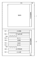
図1は、本発明の第1の実施の形態に係る撮像素子の概略構成を説明するための図である。実際には、図示の領域1と領域2が上下方向に重なっているものとする。   FIG. 1 is a diagram for explaining a schematic configuration of an image sensor according to the first embodiment of the present invention. Actually, it is assumed that the illustrated region 1 and region 2 overlap in the vertical direction.

図1において、撮像素子は、画素部101、画素部101における行を選択する垂直選択回路102、画素部101中の画素のうち垂直選択回路102によって選択される行の画素の信号を読み出して所定の処理を施す列回路103を有する。さらに、撮像素子は、列回路103で処理された信号を列毎に保持する列メモリ104、列メモリ104で保持された信号を選択する水平選択回路105、水平選択回路105で選択された列を出力回路107に読み出す出力信号線106を有する。なお、撮像素子は、図示された構成要素以外にも、例えば、垂直選択回路102、水平選択回路105、列回路103等にタイミングを提供する後述のタイミングジェネレータ1007、後述の制御回路1009、DA変換器等が組み込まれていてもよいが、これらは、撮像素子と同じ基板上に設ける必要はなく、タイミングジェネレータ1007及び制御回路1009は、図10におけるように、撮像素子とは別体に設けてもよい。   In FIG. 1, the imaging device reads out a pixel signal from a pixel portion 101, a vertical selection circuit 102 that selects a row in the pixel portion 101, and a pixel signal in a row selected by the vertical selection circuit 102 among the pixels in the pixel portion 101. The column circuit 103 that performs the process is provided. Further, the image sensor includes a column memory 104 that holds the signal processed by the column circuit 103 for each column, a horizontal selection circuit 105 that selects a signal held in the column memory 104, and a column selected by the horizontal selection circuit 105. An output signal line 106 to be read out to the output circuit 107 is provided. In addition to the components shown in the figure, the image sensor includes, for example, a timing generator 1007 described later that provides timing to the vertical selection circuit 102, horizontal selection circuit 105, column circuit 103, and the like, a control circuit 1009 described later, and DA conversion. However, the timing generator 1007 and the control circuit 1009 may be provided separately from the image sensor as shown in FIG. 10. Also good.

垂直選択回路102は、画素部101の複数の行を順に選択し、列回路103を介して、選択した行の信号を列メモリ104に出力する。水平選択回路105は、列メモリ104に保持された信号を順に選択し、出力信号線106を介して出力回路107に出力する。画素部101は、2次元の画像を提供するために、複数の画素を2次元アレイ状に配列して構成される。   The vertical selection circuit 102 sequentially selects a plurality of rows in the pixel portion 101, and outputs a signal of the selected row to the column memory 104 via the column circuit 103. The horizontal selection circuit 105 sequentially selects the signals held in the column memory 104 and outputs them to the output circuit 107 via the output signal line 106. The pixel unit 101 is configured by arranging a plurality of pixels in a two-dimensional array in order to provide a two-dimensional image.

領域1に含まれる画素部101、垂直選択回路102、及び出力回路107は、第1の半導体基板に形成される。一方、領域2に含まれる列回路103、列メモリ104、水平選択回路105、及び出力信号線106は、第2の半導体基板に形成される。第1の半導体基板と第2の半導体基板は、それぞれ別に形成され、電気的に接続が必要な配線を接続して積層されることにより、同一のパッケージに実装される。すなわち、撮像素子のパッケージの上面(画素部101の光入射面側)から俯瞰すると、第1の半導体基板の領域1に形成された画素部101の下部に、第2の半導体基板の領域2に形成された列回路103、列メモリ104、水平選択回路105、及び出力信号線106が重なるような位置に存在することになる。領域1にある垂直選択回路102や出力回路107の下の領域2に、タイミングジェネレータ1007や制御回路1009、DA変換器等を配置すると面積効率がよい。なお、以下に説明する複数の実施の形態では、第1の半導体基板と第2の半導体基板を備える構成を一例として説明するが、これに限らず、さらに別の半導体基板を備える構成でもかまわない。   The pixel portion 101, the vertical selection circuit 102, and the output circuit 107 included in the region 1 are formed on the first semiconductor substrate. On the other hand, the column circuit 103, the column memory 104, the horizontal selection circuit 105, and the output signal line 106 included in the region 2 are formed on the second semiconductor substrate. The first semiconductor substrate and the second semiconductor substrate are formed separately, and are mounted on the same package by connecting and stacking wirings that need to be electrically connected. That is, when viewed from the upper surface of the image pickup device package (on the light incident surface side of the pixel portion 101), the pixel portion 101 is formed in the region 2 of the first semiconductor substrate and the region 2 of the second semiconductor substrate. The column circuit 103, the column memory 104, the horizontal selection circuit 105, and the output signal line 106 thus formed are present at positions where they overlap. If the timing generator 1007, the control circuit 1009, the DA converter, and the like are arranged in the area 2 under the vertical selection circuit 102 and the output circuit 107 in the area 1, the area efficiency is good. In the embodiments described below, a configuration including the first semiconductor substrate and the second semiconductor substrate will be described as an example. However, the configuration is not limited thereto, and a configuration including another semiconductor substrate may be used. .

図2は、第1の実施の形態に係る撮像素子における1画素の構成及びその画素から信号を読み出す回路の構成を示す図である。   FIG. 2 is a diagram illustrating a configuration of one pixel and a configuration of a circuit that reads a signal from the pixel in the image sensor according to the first embodiment.

図2に示すように、2次元の画像を提供する画素アレイは、複数の画素を2次元アレイ状に配列して構成される。各画素201は、フォトダイオード(以下「PD」とも記す)202、転送スイッチ203、フローティングディフュージョン部(以下「FD」とも記す)204、リセットスイッチ207、増幅MOSアンプ205、選択スイッチ206を含むように構成される。リセットスイッチ207は、リセット部として機能する。   As shown in FIG. 2, a pixel array that provides a two-dimensional image is configured by arranging a plurality of pixels in a two-dimensional array. Each pixel 201 includes a photodiode (hereinafter also referred to as “PD”) 202, a transfer switch 203, a floating diffusion portion (hereinafter also referred to as “FD”) 204, a reset switch 207, an amplification MOS amplifier 205, and a selection switch 206. Composed. The reset switch 207 functions as a reset unit.

PD202は、光学系を通して入射する光を光電変換して電荷を発生する光電変換素子として機能する。PD202のアノードは接地ラインに接続され、カソードは転送スイッチ203のソースに接続される。転送スイッチ(転送ユニット)203は、そのゲート端子に入力される転送パルスφTXによって駆動され、PD202で発生した電荷をFD204に転送する。FD204は、電荷を一時的に蓄積するとともに蓄積した電荷を電圧信号に変換する電荷電圧変換部として機能する。   The PD 202 functions as a photoelectric conversion element that generates charges by photoelectrically converting light incident through the optical system. The anode of the PD 202 is connected to the ground line, and the cathode is connected to the source of the transfer switch 203. The transfer switch (transfer unit) 203 is driven by a transfer pulse φTX input to its gate terminal, and transfers the charge generated in the PD 202 to the FD 204. The FD 204 functions as a charge-voltage conversion unit that temporarily accumulates charges and converts the accumulated charges into a voltage signal.

増幅MOSアンプ(増幅部)205は、MOSFET等の増幅回路で構成され、ソースフォロアとして機能し、そのゲートにはFD204で電荷電圧変換された信号が入力される。また、増幅MOSアンプ205は、そのドレインが第1電位を供給する第1電源線VDD1に接続され、そのソースが選択スイッチ206に接続されている。選択スイッチ206は、そのゲートに入力される垂直選択パルスφSELによって駆動され、そのドレインが増幅MOSアンプ205に接続され、そのソースが垂直信号線208に接続されている。垂直選択パルスφSELがアクティブレベル(ハイレベル)になると、画素アレイの該当する行に属する画素の選択スイッチ206が導通状態になり、増幅MOSアンプ205のソースが垂直信号線208に接続される。   The amplification MOS amplifier (amplification unit) 205 is configured by an amplification circuit such as a MOSFET and functions as a source follower, and a signal that has been subjected to charge-voltage conversion by the FD 204 is input to its gate. The amplification MOS amplifier 205 has its drain connected to the first power supply line VDD1 that supplies the first potential, and its source connected to the selection switch 206. The selection switch 206 is driven by a vertical selection pulse φSEL input to its gate, its drain is connected to the amplification MOS amplifier 205, and its source is connected to the vertical signal line 208. When the vertical selection pulse φSEL becomes an active level (high level), the selection switches 206 of the pixels belonging to the corresponding row of the pixel array are turned on, and the source of the amplification MOS amplifier 205 is connected to the vertical signal line 208.

リセットスイッチ(リセットユニット)207は、そのドレインが定電位である第2電位(リセット電位)を供給する第2電源線VDD2に接続され、そのソースがFD204に接続されている。また、リセットスイッチ207は、そのゲートに入力されるリセットパルスφRESによって駆動され、FD204に蓄積されている電荷を除去する。φTX、φSEL、及びφRESは、垂直選択回路102から供給される。   The reset switch (reset unit) 207 has a drain connected to a second power supply line VDD2 that supplies a second potential (reset potential) that is a constant potential, and a source connected to the FD 204. The reset switch 207 is driven by a reset pulse φRES input to its gate, and removes charges accumulated in the FD 204. φTX, φSEL, and φRES are supplied from the vertical selection circuit 102.

FD204及び増幅MOSアンプ205のほか、垂直信号線208に定電流を供給する定電流源209によってフローティングディフュージョンアンプが構成される。選択スイッチ206で選択された行を構成する各画素において、PD202からFD204に転送される電荷がFD204で電圧信号に変換されて、フローティングディフュージョンアンプを通じて列毎に設けられた垂直信号線(列信号線)208に出力される。   In addition to the FD 204 and the amplification MOS amplifier 205, the constant current source 209 that supplies a constant current to the vertical signal line 208 forms a floating diffusion amplifier. In each pixel constituting the row selected by the selection switch 206, the charge transferred from the PD 202 to the FD 204 is converted into a voltage signal by the FD 204, and a vertical signal line (column signal line) provided for each column through the floating diffusion amplifier. ) 208 is output.

垂直信号線(列信号線)208の各々に接続された列回路103は、CDS(相関2重サンプリング)回路やゲインアンプなどで構成される。CDS回路は、垂直信号線208に出力された信号に相関2重サンプリング処理を施す。また、ゲインアンプは、垂直信号線208に出力された信号を所定の増幅率で増幅する。また、列回路103は、列毎に同様の構成の回路で形成される。列回路103で上記処理を施された信号は、各々対応する列メモリ104に保持される。列メモリ104で保持された信号は、出力信号線106を介して出力回路107に転送される。出力回路107は、入力された信号に対して増幅やインピーダンス変換などを行い、撮像素子の外部に信号を出力する。   The column circuit 103 connected to each of the vertical signal lines (column signal lines) 208 includes a CDS (correlated double sampling) circuit, a gain amplifier, and the like. The CDS circuit performs correlated double sampling processing on the signal output to the vertical signal line 208. The gain amplifier amplifies the signal output to the vertical signal line 208 with a predetermined amplification factor. The column circuit 103 is formed of a circuit having the same configuration for each column. The signals subjected to the above processing in the column circuit 103 are held in the corresponding column memories 104, respectively. The signal held in the column memory 104 is transferred to the output circuit 107 via the output signal line 106. The output circuit 107 performs amplification and impedance conversion on the input signal and outputs the signal to the outside of the image sensor.

列回路103、列メモリ104、及び出力回路107は、前述のような回路構成をとることもできるが、列回路103に列毎にAD変換器をもったタイプでもよい。その場合は、列回路103は、CDS回路やゲインアンプに加え、AD変換器を有する。また、その際の列メモリ104はデジタルのメモリであり、出力回路107には、LVDS(Low Voltage Differential Signaling)ドライバーなどの構成要素も含まれる。   The column circuit 103, the column memory 104, and the output circuit 107 can have the above-described circuit configuration, but may be a type in which the column circuit 103 includes an AD converter for each column. In that case, the column circuit 103 includes an AD converter in addition to the CDS circuit and the gain amplifier. In this case, the column memory 104 is a digital memory, and the output circuit 107 includes components such as an LVDS (Low Voltage Differential Signaling) driver.

図示の領域1すなわち第1半導体基板には、画素毎に設けられた、PD202、転送スイッチ203、FD204、リセットスイッチ207、増幅MOSアンプ205、及び選択スイッチ206、ならびに出力回路107を含むように構成されている。   The illustrated region 1, that is, the first semiconductor substrate includes a PD 202, a transfer switch 203, an FD 204, a reset switch 207, an amplification MOS amplifier 205, a selection switch 206, and an output circuit 107 provided for each pixel. Has been.

図示の領域2すなわち第2半導体基板には、列毎に設けられた、垂直信号線208、定電流源209、列回路103、列メモリ104、及び出力信号線106を含むように構成されている。なお、垂直信号線(列信号線)208は、画素部101と列回路103を接続する配線であり、領域1または領域2のどちらに含まれていてもよい。また、選択スイッチ206は領域2に含まれていてもよい。   The illustrated region 2, that is, the second semiconductor substrate is configured to include a vertical signal line 208, a constant current source 209, a column circuit 103, a column memory 104, and an output signal line 106 provided for each column. . Note that the vertical signal line (column signal line) 208 is a wiring for connecting the pixel portion 101 and the column circuit 103 and may be included in either the region 1 or the region 2. The selection switch 206 may be included in the region 2.

また、図3に示す回路構成の変形例のように、定電流源209は領域1にあってもよい。ただし、この場合は定電流源209を画素と同一の基板に配置するため、あまり面積効率はよくない。画素部の面積より、列回路103、列メモリ104、出力信号線106などの構成面積が大きい場合にのみ、有効である。   Further, the constant current source 209 may be in the region 1 as in a modification of the circuit configuration shown in FIG. However, in this case, since the constant current source 209 is arranged on the same substrate as the pixel, the area efficiency is not so good. This is effective only when the configuration area of the column circuit 103, the column memory 104, the output signal line 106, and the like is larger than the area of the pixel portion.

また、図4で示す回路構成の他の変形例のように、選択スイッチ206がない構成であってもよい。選択スイッチ206がない構成においては、ΦRESと第2電源線VDD2の電位を制御することで、選択行と非選択行の設定を行う。   Further, a configuration without the selection switch 206 may be used as in another modification of the circuit configuration shown in FIG. In the configuration without the selection switch 206, the selected row and the non-selected row are set by controlling the potential of ΦRES and the second power supply line VDD2.

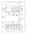
図5は、本発明の第1の実施形態に係る撮像素子の断面構造を表わす図である。第1半導体基板を表す領域1が第2半導体基板を表す領域2の上に積層された構造を示している。図2に示す構成要素と同じものについては同一の符合を付す。   FIG. 5 is a diagram illustrating a cross-sectional structure of the image sensor according to the first embodiment of the present invention. A structure in which a region 1 representing a first semiconductor substrate is stacked on a region 2 representing a second semiconductor substrate is shown. The same components as those shown in FIG.

第1半導体基板を表わす領域1は、半導体基板501上に形成される。領域1は、第1導電型の領域502、PDの領域202、PD202の暗電流を抑制するための、第1導電型の領域503を備える。また、転送スイッチ203、FD204、増幅MOSアンプ205を備える。この他にも、リセットスイッチ207も含む。   Region 1 representing the first semiconductor substrate is formed on semiconductor substrate 501. The region 1 includes a first conductivity type region 502, a PD region 202, and a first conductivity type region 503 for suppressing dark current in the PD 202. In addition, a transfer switch 203, an FD 204, and an amplification MOS amplifier 205 are provided. In addition, a reset switch 207 is also included.

さらに、素子分離領域504、多層に形成された配線層505、多層配線層505間の層間膜506を備える。スルーホール507は、配線間を電気的に接続する。領域1は画素部を含むため、色分離を行うカラーフィルター508や、光を集光するマイクロレンズ509も含む。   Further, an element isolation region 504, a multilayer wiring layer 505, and an interlayer film 506 between the multilayer wiring layers 505 are provided. The through hole 507 electrically connects the wirings. Since the region 1 includes a pixel portion, the region 1 also includes a color filter 508 that performs color separation and a microlens 509 that collects light.

第1半導体基板以外の半導体基板として第2半導体基板を表わす領域2は、半導体基板510上に形成される。各スイッチ群511の複数種類のスイッチにより列回路103の各回路が形成される。また、領域2は、列メモリ104、出力信号線106なども含む。垂直信号線208の接続ポイント115は、マイクロバンプ等で領域1と領域2を電気的に接続する。また、垂直信号線208の接続ポイント115以外にも、電源や各種駆動パルスなどを供給する配線同士が、マイクロバンプ等の接続ポイント512で接続される。なお、本実施の形態では、裏面照射タイプで受光部を形成した第1半導体基板を図示したが、裏面照射タイプでなく、表面照射タイプでもよい。   Region 2 representing the second semiconductor substrate as a semiconductor substrate other than the first semiconductor substrate is formed on semiconductor substrate 510. Each circuit of the column circuit 103 is formed by a plurality of types of switches in each switch group 511. The region 2 also includes a column memory 104, an output signal line 106, and the like. The connection point 115 of the vertical signal line 208 electrically connects the region 1 and the region 2 with a micro bump or the like. In addition to the connection point 115 of the vertical signal line 208, wirings for supplying power, various drive pulses, and the like are connected by connection points 512 such as micro bumps. In the present embodiment, the first semiconductor substrate in which the light receiving portion is formed by the backside illumination type is illustrated, but the backside illumination type may be used instead of the backside illumination type.

本実施の形態では、図1のように、領域1に画素部101、垂直選択回路102、及び出力回路107を形成し、その他の駆動回路は領域2に配置したが、これに限定するものではない。例えば、図6の撮像素子の全体構成の変形例のように、出力回路107を領域2に配置してもよい。   In this embodiment mode, as shown in FIG. 1, the pixel portion 101, the vertical selection circuit 102, and the output circuit 107 are formed in the region 1, and the other driving circuits are arranged in the region 2. However, the present invention is not limited to this. Absent. For example, the output circuit 107 may be arranged in the region 2 as in a modification of the overall configuration of the image sensor in FIG.

また、図7の撮像素子の全体構成の他の変形例に示すように、垂直選択回路102の一部を領域1に、垂直選択回路102の残りを領域2に配置してもよい。また、その際には、上から俯瞰した際に略同一の箇所に配置することで、面積効率を上げることもできる。つまり、本発明においては、画素部101のうち、FD204を領域1および領域2に分断することがないように、少なくとも転送スイッチ203、FD204、リセットスイッチ207、増幅MOSアンプ205が領域1にあればよい。その他の駆動回路は半導体基板の面積効率に応じて、領域1に配置されていても、領域2に配置されていてもよい。   Further, as shown in another modification of the overall configuration of the imaging device in FIG. 7, a part of the vertical selection circuit 102 may be arranged in the region 1 and the rest of the vertical selection circuit 102 may be arranged in the region 2. Moreover, in that case, area efficiency can also be improved by arrange | positioning in the substantially same location when it overlooks from the top. In other words, in the present invention, if at least the transfer switch 203, the FD 204, the reset switch 207, and the amplification MOS amplifier 205 are in the region 1 so that the FD 204 is not divided into the region 1 and the region 2 in the pixel portion 101. Good. Other driving circuits may be arranged in the region 1 or in the region 2 depending on the area efficiency of the semiconductor substrate.

上記実施の形態では、図5に示すように、領域1を第1の半導体基板、領域2を第2の半導体基板としているが、これに限定するものではなく、図8に示すように、同一の半導体基板に形成してもよい。   In the above embodiment, as shown in FIG. 5, the region 1 is the first semiconductor substrate and the region 2 is the second semiconductor substrate. However, the present invention is not limited to this, and as shown in FIG. It may be formed on the semiconductor substrate.

図8は、本発明の第2の実施の形態に係る撮像素子の断面構造を表わす図である。図2に示す構成要素と図5に示す構成要素と同じものについては同一の符合を付してそれらの説明は省略する。   FIG. 8 is a diagram illustrating a cross-sectional structure of an image sensor according to the second embodiment of the present invention. The same components as those shown in FIG. 2 and the components shown in FIG. 5 are given the same reference numerals, and descriptions thereof are omitted.

図8に示す第2の実施の形態においては、半導体基板501の表面(第1面または第2面)、裏面(第1面または第2面)にそれぞれ領域1、領域2が形成されている。本実施の形態では、領域1が形成された側を表面、領域2が形成された側を裏面として説明する。保護層801は、裏面の配線層505を保護する。プラグ802は、表面と裏面を電気的に接続する。   In the second embodiment shown in FIG. 8, a region 1 and a region 2 are formed on the front surface (first surface or second surface) and back surface (first surface or second surface) of the semiconductor substrate 501, respectively. . In the present embodiment, the side on which the region 1 is formed is described as the front surface, and the side on which the region 2 is formed is described as the back surface. The protective layer 801 protects the wiring layer 505 on the back surface. The plug 802 electrically connects the front surface and the back surface.

また、上記実施の形態では、領域1、領域2として説明したが、2つの領域に限定するものではなく、複数の領域に分割して、各構成要素を配置してもよい。例えば、図9に示す変形例のように、領域1に画素部101、垂直選択回路102を形成し、残りの駆動回路を領域2、領域3に分割して形成するように構成してもよい。図示例では、領域2に、垂直選択回路102の残りと列回路103が形成され、領域3に、列回路103の残りとその他の駆動回路が別々に形成されている。このように、複数の領域にまたがって各構成要素を別々に配置することで、列毎にAD変換器などを搭載し、増大する列回路103の配置を有効に行うことが可能となる。なお、領域1、領域2、領域3をそれぞれ別々の半導体基板に形成してもかまわない。   In the embodiment described above, the regions 1 and 2 have been described. However, the present invention is not limited to two regions, and each component may be arranged by being divided into a plurality of regions. For example, as in the modification shown in FIG. 9, the pixel unit 101 and the vertical selection circuit 102 may be formed in the region 1 and the remaining driving circuits may be divided into the region 2 and the region 3. . In the illustrated example, the remainder of the vertical selection circuit 102 and the column circuit 103 are formed in the area 2, and the remainder of the column circuit 103 and other drive circuits are separately formed in the area 3. In this way, by disposing each component separately over a plurality of regions, it is possible to mount an AD converter or the like for each column and effectively arrange the increasing column circuit 103. Note that the region 1, the region 2, and the region 3 may be formed on separate semiconductor substrates.

図10は、上述した実施の形態及び変形例のいずれかに係る撮像素子を搭載した撮像装置の一例であるデジタルカメラの概略構成を示す図である。   FIG. 10 is a diagram illustrating a schematic configuration of a digital camera that is an example of an imaging apparatus equipped with an imaging device according to any of the above-described embodiments and modifications.

図10において、被写体の光学像を固体撮像素子(実施の形態及び変形例のいずれかに係る撮像素子)1005に結像させるレンズ部1001は、レンズ駆動装置1002によってズーム制御、フォーカス制御、絞り制御などが行われる。メカニカルシャッター1003は、シャッター制御ユニット1004によって制御される。固体撮像素子1005は、レンズ部1001で結像された被写体像を画像信号に変換して出力する。撮像信号処理回路1006は、固体撮像素子1005から出力される画像信号に各種の補正を行ったり、データを圧縮したりする。   In FIG. 10, a lens unit 1001 that forms an optical image of a subject on a solid-state imaging device (an imaging device according to any of the embodiments and modifications) 1005 is controlled by a lens driving device 1002 to perform zoom control, focus control, and aperture control. Etc. are performed. The mechanical shutter 1003 is controlled by the shutter control unit 1004. The solid-state image sensor 1005 converts the subject image formed by the lens unit 1001 into an image signal and outputs the image signal. The imaging signal processing circuit 1006 performs various corrections on the image signal output from the solid-state imaging device 1005 and compresses data.

タイミングジェネレータ1007は、固体撮像素子1005、撮像信号処理回路1006に、各種タイミング信号を出力する駆動ユニットである。制御回路1009は、各種演算と撮像装置全体を制御する。メモリ1008は、画像データを一時的に記憶する。記録媒体制御インターフェース1010は、半導体メモリ等の着脱可能な記録媒体1011に記録または読み出しを行う。表示部1012は、各種情報や撮影画像を表示する。   The timing generator 1007 is a drive unit that outputs various timing signals to the solid-state imaging device 1005 and the imaging signal processing circuit 1006. A control circuit 1009 controls various calculations and the entire imaging apparatus. The memory 1008 temporarily stores image data. The recording medium control interface 1010 performs recording or reading on a detachable recording medium 1011 such as a semiconductor memory. The display unit 1012 displays various information and captured images.

次に、前述の構成を有するデジタルカメラの撮影時の動作について説明する。   Next, the operation at the time of shooting of the digital camera having the above-described configuration will be described.

不図示のメイン電源がオンされると、コントロール系の電源がオンし、更に撮像信号処理回路1006などの撮像系回路の電源がオンされる。つづいて、不図示のレリーズボタンが押されると、測距装置1014から出力された信号をもとに、高周波成分を取り出し、被写体までの距離の演算を制御回路1009で行う。その後、レンズ駆動装置1002によりレンズ部1001を駆動して合焦か否かを判断し、合焦していないと判断したときは、再びレンズ部1001を駆動して測距を行う。そして、合焦が確認された後に撮影動作が開始する。   When a main power supply (not shown) is turned on, the power supply for the control system is turned on, and further, the power supply for the imaging system circuit such as the imaging signal processing circuit 1006 is turned on. Subsequently, when a release button (not shown) is pressed, a high-frequency component is extracted based on a signal output from the distance measuring device 1014, and the distance to the subject is calculated by the control circuit 1009. Thereafter, the lens driving device 1002 drives the lens unit 1001 to determine whether it is in focus. When it is determined that the lens unit 1001 is not in focus, the lens unit 1001 is driven again to perform distance measurement. Then, after the in-focus state is confirmed, the photographing operation starts.

撮影動作が終了すると、固体撮像素子1005から出力された画像信号は、撮像信号処理回路1006で画像処理され、制御回路1009によりメモリ1008に書き込まれる。メモリ1008に蓄積されたデータは、制御回路1009の制御により記録媒体制御I/F部1010を通り、半導体メモリ等の着脱可能な記録媒体1011に記録される。なお、図示しない外部I/F部を通り直接コンピュータ等に入力して画像の加工を行ってもよい。   When the photographing operation is completed, the image signal output from the solid-state imaging device 1005 is subjected to image processing by the imaging signal processing circuit 1006 and written to the memory 1008 by the control circuit 1009. Data stored in the memory 1008 passes through the recording medium control I / F unit 1010 under the control of the control circuit 1009 and is recorded on a removable recording medium 1011 such as a semiconductor memory. Note that the image processing may be performed by directly entering a computer or the like through an external I / F unit (not shown).

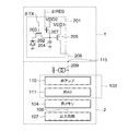
図11は、本発明の第3の実施の形態の撮像素子における1画素の構成及びその画素から信号を読み出す回路構成を示す図である。領域1は、第1の半導体基板に形成された回路を有するチップであり、領域2は、第2の半導体基板に形成された回路を有するチップである。   FIG. 11 is a diagram illustrating a configuration of one pixel and a circuit configuration for reading a signal from the pixel in the image sensor according to the third embodiment of the present invention. Region 1 is a chip having a circuit formed on a first semiconductor substrate, and region 2 is a chip having a circuit formed on a second semiconductor substrate.

領域1の中には、主に画素201を有し、領域2の中には、主に画素201からの信号を処理する列回路を有する。   The region 1 mainly includes pixels 201, and the region 2 includes column circuits that mainly process signals from the pixels 201.

領域1は、2次元の画像を提供する画素アレイとして、複数の画素201を2次元アレイ状に配列して構成される。各画素201は、フォトダイオード(以下、PDとも記す)202、転送スイッチ203、フローティングディフュージョン部(以下、FDとも記す)204、増幅MOSアンプ205、選択スイッチ206及び、リセットスイッチ207を含んで構成されうる。   The region 1 is configured by arranging a plurality of pixels 201 in a two-dimensional array as a pixel array that provides a two-dimensional image. Each pixel 201 includes a photodiode (hereinafter also referred to as PD) 202, a transfer switch 203, a floating diffusion portion (hereinafter also referred to as FD) 204, an amplification MOS amplifier 205, a selection switch 206, and a reset switch 207. sell.

PD202は、光学系を通して入射する光を光電変換して電荷を発生する光電変換部として機能する。PD202のアノードは接地ラインに接続され、カソードは転送スイッチ203のソースに接続される。転送部としての転送スイッチ203は、そのゲート端子に入力される転送パルスφTXによって駆動され、PD202で発生した電荷をFD204に転送する。FD204は、電荷を一時的に蓄積するとともに蓄積した電荷を電圧信号に変換する電荷電圧変換部として機能する。   The PD 202 functions as a photoelectric conversion unit that generates charges by photoelectrically converting light incident through the optical system. The anode of the PD 202 is connected to the ground line, and the cathode is connected to the source of the transfer switch 203. The transfer switch 203 as a transfer unit is driven by a transfer pulse φTX input to its gate terminal, and transfers the charge generated in the PD 202 to the FD 204. The FD 204 functions as a charge-voltage conversion unit that temporarily accumulates charges and converts the accumulated charges into a voltage signal.

増幅MOSアンプ205は、ソースフォロアとして機能し、そのゲートにはFD204で電荷電圧変換された信号が入力される。また、増幅MOSアンプ205は、そのドレインが第1電位を供給する第1電源線VDD1に接続され、そのソースが選択スイッチ206に接続されている。選択スイッチ206は、そのゲートに入力される垂直選択パルスφSELによって駆動され、そのドレインが増幅MOSアンプ205に接続され、そのソースが垂直信号線208に接続されている。垂直選択パルスφSELがアクティブレベル(ハイレベル)になると、画素アレイの該当する行に属する画素の選択スイッチ206が導通状態になり、増幅MOSアンプ205のソースが垂直信号線208に接続される。垂直信号線208は列を共有する複数の画素201で共有される。   The amplification MOS amplifier 205 functions as a source follower, and a signal that has been subjected to charge-voltage conversion by the FD 204 is input to its gate. The amplification MOS amplifier 205 has its drain connected to the first power supply line VDD1 that supplies the first potential, and its source connected to the selection switch 206. The selection switch 206 is driven by a vertical selection pulse φSEL input to its gate, its drain is connected to the amplification MOS amplifier 205, and its source is connected to the vertical signal line 208. When the vertical selection pulse φSEL becomes an active level (high level), the selection switches 206 of the pixels belonging to the corresponding row of the pixel array are turned on, and the source of the amplification MOS amplifier 205 is connected to the vertical signal line 208. The vertical signal line 208 is shared by a plurality of pixels 201 sharing a column.

リセットスイッチ207は、そのドレインが第2電位(リセット電位)を供給する第2電源線VDD2に接続され、そのソースがFD204に接続されていて、そのゲートに入力されるリセットパルスφRESによって駆動されて、FD204に蓄積されている電荷を除去する。   The reset switch 207 has a drain connected to the second power supply line VDD2 for supplying a second potential (reset potential), a source connected to the FD 204, and is driven by a reset pulse φRES input to the gate. , The charge accumulated in the FD 204 is removed.

FD204及び増幅MOSアンプ205他、垂直信号線208に定電流を供給する定電流源209によってフローティングディフュージョンアンプが構成される。選択スイッチ206で選択された行を構成する各画素において、PD202からFD204に転送される電荷がFD204で電圧信号に変換されて、フローティングディフュージョンアンプを通じて列毎に設けられた垂直信号線(列信号線)208に出力される。φTX、φSEL、φRESは後述する垂直選択回路から供給される。   In addition to the FD 204 and the amplification MOS amplifier 205, a floating diffusion amplifier is configured by a constant current source 209 that supplies a constant current to the vertical signal line 208. In each pixel constituting the row selected by the selection switch 206, the charge transferred from the PD 202 to the FD 204 is converted into a voltage signal by the FD 204, and a vertical signal line (column signal line) provided for each column through the floating diffusion amplifier. ) 208 is output. φTX, φSEL, and φRES are supplied from a vertical selection circuit described later.

垂直信号線(列信号線)208の各々に接続された列回路103は、列アンプ110などで構成される。列回路103は、各列同様の構成の回路で形成される。列回路103は、図11で示した列アンプ110だけの構成であってもよいし、CDS(相関2重サンプリング)回路などを含む構成であってもよい。   The column circuit 103 connected to each of the vertical signal lines (column signal lines) 208 includes a column amplifier 110 and the like. The column circuit 103 is formed by a circuit having the same configuration as each column. The column circuit 103 may have a configuration including only the column amplifier 110 illustrated in FIG. 11 or may include a CDS (correlated double sampling) circuit.

列回路103で各種処理を施された信号は、各々対応する列メモリ104に保持される。列メモリ104で保持された信号は、出力信号線106を介し、出力回路107に転送される。出力回路107は、増幅やインピーダンス変換などを行い、撮像素子の外部に信号を出力する。   Signals subjected to various processes in the column circuit 103 are held in the corresponding column memories 104, respectively. The signal held in the column memory 104 is transferred to the output circuit 107 via the output signal line 106. The output circuit 107 performs amplification, impedance conversion, and the like, and outputs a signal to the outside of the image sensor.

領域1と領域2は垂直信号線(列信号線)208の接続ポイント115を介して、電気的に接続される。図11に示すように接続ポイント115を増幅MOSアンプ205より後にすることで、PRNUやDSNUを低減することが可能となる。定電流源209は領域2にあってもよいし、領域1にあってもよい。   Region 1 and region 2 are electrically connected via a connection point 115 of a vertical signal line (column signal line) 208. As shown in FIG. 11, by connecting the connection point 115 after the amplification MOS amplifier 205, it is possible to reduce PRNU and DSNU. The constant current source 209 may be in the region 2 or the region 1.

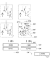
図12は、図11の撮像素子回路の変形例を示す図である。   FIG. 12 is a diagram illustrating a modification of the image sensor circuit of FIG.

図12では、列アンプ110の後に列AD111を搭載している。列AD111は、列毎のADコンバーターであり、AD変換を行う。この場合、列回路103は列アンプ110、列AD111で構成される。また、前述したCDS回路等を含んでもよい。列AD111を有する構成の場合は、列メモリ104はデジタルのメモリであり、出力回路107は、LVDSドライバーなどの構成要素も含まれる。   In FIG. 12, the column AD 111 is mounted after the column amplifier 110. The column AD111 is an AD converter for each column, and performs AD conversion. In this case, the column circuit 103 includes a column amplifier 110 and a column AD111. Further, the CDS circuit described above may be included. In the case of a configuration having the column AD111, the column memory 104 is a digital memory, and the output circuit 107 includes components such as an LVDS driver.

また、図13で示すもう1つの変形例のように、選択スイッチ206がない構成でもよい。   Further, a configuration without the selection switch 206 may be used as in another modification shown in FIG.

図14は、第3の実施の形態の撮像素子の概略を上から俯瞰した図である。領域1と領域2は、それぞれ別の半導体基板上に形成されたチップであり、電気的に接続が必要な配線を接続して、同一のパッケージに実装される。すなわちパッケージの上面から俯瞰すると、領域1の下に領域2が重なって配置されている。   FIG. 14 is an overhead view of the outline of the image sensor according to the third embodiment. Region 1 and region 2 are chips formed on different semiconductor substrates, and are mounted on the same package by connecting wirings that need to be electrically connected. That is, when viewed from the top surface of the package, the region 2 is disposed so as to overlap the region 1.

領域1は、画素201が複数行、複数列にアレイ上に形成されている。画素201を駆動するための、前述のφTX、φSEL、φRESが行毎に垂直選択回路102から供給される。画素から信号を取り出す垂直信号線208は同一列の画素毎に共有される。ここでは、1から4列目までの垂直信号線208を各々208_1、208_2、208_3、208_4と示している。領域1と領域2には垂直信号線208を列回路103に接続するための接続ポイント115を有する。垂直信号線208_1が有する接続ポイント115を115_1と示す。また、垂直信号線208_1とつながる列回路103を103_1と示し、列回路103_1とつながる列メモリ104を104_1と示す。領域2には、列メモリ104の信号を出力回路107に転送するための水平選択回路105を有する。水平選択回路105は列メモリ104の信号を時系列に出力回路107に転送する。   In the region 1, the pixels 201 are formed on the array in a plurality of rows and a plurality of columns. The aforementioned φTX, φSEL, and φRES for driving the pixel 201 are supplied from the vertical selection circuit 102 for each row. A vertical signal line 208 for extracting a signal from a pixel is shared for each pixel in the same column. Here, the vertical signal lines 208 in the first to fourth columns are denoted as 208_1, 208_2, 208_3, and 208_4, respectively. Region 1 and region 2 have a connection point 115 for connecting the vertical signal line 208 to the column circuit 103. A connection point 115 included in the vertical signal line 208_1 is denoted as 115_1. Further, the column circuit 103 connected to the vertical signal line 208_1 is denoted as 103_1, and the column memory 104 connected to the column circuit 103_1 is denoted as 104_1. The area 2 has a horizontal selection circuit 105 for transferring the signal of the column memory 104 to the output circuit 107. The horizontal selection circuit 105 transfers the signal of the column memory 104 to the output circuit 107 in time series.

なお、図示しないが領域1および領域2のいずれかには、図示された構成要素以外にも、前述の定電流源209を有する。定電流源209は列回路103の中に含まれてもよい。また、他にも例えば、垂直選択回路102、水平選択回路105、列回路103等にタイミングを提供するタイミングジェネレータ或いは制御回路や、シリアル通信インターフェース、DA変換器等を有する。   In addition, although not illustrated, in any one of the region 1 and the region 2, the above-described constant current source 209 is provided in addition to the illustrated components. The constant current source 209 may be included in the column circuit 103. In addition, for example, a timing generator or control circuit that provides timing to the vertical selection circuit 102, the horizontal selection circuit 105, the column circuit 103, and the like, a serial communication interface, a DA converter, and the like are included.

水平選択回路105には、タイミングジェネレータ等より各種パルスが供給されるので、チップの端に近い所にあることが望ましい。図14で示すように、接続ポイント115を列方向の中央付近にもってくることによって、水平選択回路105を上下方向に配置することが可能となる。なお、接続ポイント115を列方向の周辺付近にもってくることもできる。   Since various pulses are supplied to the horizontal selection circuit 105 from a timing generator or the like, it is desirable that the horizontal selection circuit 105 be near the end of the chip. As shown in FIG. 14, the horizontal selection circuit 105 can be arranged in the vertical direction by bringing the connection point 115 near the center in the column direction. Note that the connection point 115 can be brought near the periphery in the column direction.

本実施の形態に係る撮像素子の断面構造は、図5に示した第1の実施の形態のそれと略同一であるので、図示と説明を省略する。   Since the cross-sectional structure of the image sensor according to the present embodiment is substantially the same as that of the first embodiment shown in FIG. 5, illustration and description thereof are omitted.

図14で示したように、接続ポイント115が各垂直信号線(列信号線)上で各列の画素によって共有されることによって、接続ポイントを画素毎に有した場合に対し、接続ポイント数が少ないので、接続ポイントの形成不良による歩留りが低減してしまう課題も解決することが可能となる。もちろん、接続ポイントは、1点でなく、歩留りを考慮して数点あってもよい。本実施の形態では領域1側の垂直信号線で画素を共有することによって、各画素毎に領域1と領域2をつなぐ必要がなくなっている。   As shown in FIG. 14, the connection point 115 is shared by the pixels of each column on each vertical signal line (column signal line), so that the number of connection points is smaller than when there is a connection point for each pixel. Since there are few, the subject that the yield by the formation failure of a connection point reduces can also be solved. Of course, the number of connection points is not limited to one, but may be several in consideration of yield. In the present embodiment, the pixels are shared by the vertical signal lines on the region 1 side, so that it is not necessary to connect the region 1 and the region 2 for each pixel.

なお、ここでは、裏面照射タイプで受光部を形成した第1半導体基板を図示したが、裏面照射タイプでなく、表面照射タイプでもよい。図15は本実施の形態の変形例の表面照射タイプの断面構造を表わす図である。第2半導体基板を表す領域2の上に第1半導体基板を表す領域1が積層された構造を示している。図5と同一の符号の構成要素については説明を省略する。表面照射タイプの場合は、マイクロレンズ509が半導体基板501に対して、配線505の上部に設置される。表面照射タイプの場合は接続ポイント115と領域1の構成要素を接続するため、貫通ビア601を形成する。   In addition, although the 1st semiconductor substrate which formed the light-receiving part with the back irradiation type was shown here, the front surface irradiation type may be sufficient instead of a back surface irradiation type. FIG. 15 is a diagram showing a cross-sectional structure of a surface irradiation type according to a modification of the present embodiment. A structure in which a region 1 representing a first semiconductor substrate is stacked on a region 2 representing a second semiconductor substrate is shown. The description of the components having the same reference numerals as those in FIG. 5 is omitted. In the case of the surface irradiation type, the microlens 509 is installed above the wiring 505 with respect to the semiconductor substrate 501. In the case of the surface irradiation type, a through via 601 is formed in order to connect the connection point 115 and the components of the region 1.

表面照射タイプの領域1と領域2を同一基板501に形成した本発明の第4の実施の形態の断面構造は、図8に示した第2の実施の形態のそれと実質的に同じであるので、図示と説明を省略するが、前述したように、この場合は、接続ポイント115は垂直信号線208と裏面側の回路を接続するために、貫通ビア601となる。   The cross-sectional structure of the fourth embodiment of the present invention in which the surface irradiation type region 1 and region 2 are formed on the same substrate 501 is substantially the same as that of the second embodiment shown in FIG. Although illustration and description are omitted, as described above, in this case, the connection point 115 becomes the through via 601 in order to connect the vertical signal line 208 and the circuit on the back surface side.

図16は、本発明の第5の実施の形態の撮像素子の全体構成を上から俯瞰した図である。図17及び図18は、その変形例をそれぞれ示した図である。   FIG. 16 is an overhead view of the entire configuration of the image sensor according to the fifth embodiment of the present invention. FIG. 17 and FIG. 18 are diagrams showing modifications thereof, respectively.

図14で示した図と異なり、図16に示す第5の実施の形態の撮像素子の全体構成では、接続ポイント115である115_1、115_2が列に沿う方向にずれることによって、列回路103_1、103_2の直近に接続ポイント115を配置することが可能となる。それによって、領域2での配線長が短くなり、さらに効率的に列回路103等を配置することが可能となる。   Unlike the diagram shown in FIG. 14, in the overall configuration of the image sensor of the fifth embodiment shown in FIG. It is possible to place the connection point 115 in the immediate vicinity. Accordingly, the wiring length in the region 2 is shortened, and the column circuit 103 and the like can be arranged more efficiently.

図17の変形例では、接続ポイント115_1、115_2、115_3、115_4をずらすことによって、列回路103_1から110_4の配置をまばらに配置することが可能となる。図14のように、列回路103が画面対応領域で偏った配置の場合は、列回路103の発熱が集中し、列回路103からの熱をうけたPD202によって、撮影画像の画面対応領域内で暗電流の不均一性が発生してしまう。しかし、図17のような構成、例えば、均等配置をとることによって、画面対応領域内で列回路103の発熱による暗電流の不均一性を低減することが可能となる。図17では、列回路103_1、列メモリ104_1と列回路103_3、列メモリ104_3の配置を逆転させることによって、列回路103を分散している。そのため、列に沿う方向の中央にも出力信号線106を配置する工夫をしている。ただし、列回路103や列メモリ104が十分に小さい構成をとれる図18のような場合においては、その必要はなく、列回路103_1と103_3は同一方向の配置でもよい。   In the modified example of FIG. 17, it is possible to sparsely arrange the column circuits 103_1 to 110_4 by shifting the connection points 115_1, 115_2, 115_3, and 115_4. As shown in FIG. 14, when the column circuit 103 is biased in the screen corresponding area, the heat generated in the column circuit 103 is concentrated, and the PD 202 that has received heat from the column circuit 103 is within the screen corresponding area of the photographed image. Dark current non-uniformity occurs. However, by adopting the configuration as shown in FIG. 17, for example, an equal arrangement, it is possible to reduce dark current non-uniformity due to heat generated by the column circuit 103 in the screen corresponding region. In FIG. 17, the column circuit 103 is distributed by reversing the arrangement of the column circuit 103_1, the column memory 104_1, the column circuit 103_3, and the column memory 104_3. Therefore, the output signal line 106 is arranged at the center in the direction along the column. However, in the case shown in FIG. 18 in which the column circuit 103 and the column memory 104 can have a sufficiently small configuration, this is not necessary, and the column circuits 103_1 and 103_3 may be arranged in the same direction.

上述したように、接続ポイント115を列毎にずらすことによって、効率的な配置と、列回路103の発熱の影響を軽減させる配置が可能となる。   As described above, by shifting the connection point 115 for each column, an efficient arrangement and an arrangement for reducing the influence of heat generated in the column circuit 103 are possible.

図19は、本発明の第6の実施の形態の撮像素子の全体構成を上から俯瞰した図である。図20及び図21は、その変形例をそれぞれ示した図である。   FIG. 19 is an overhead view of the entire configuration of the image sensor according to the sixth embodiment of the present invention. 20 and 21 are diagrams showing modifications thereof, respectively.

図14、16、17、18では、列回路103や列メモリ104は行に沿う方向に2列分の幅を有する回路として記載したが、本発明ではそれ以外の構成もとりうることが可能であり、その構成に限定されるものではない。たとえば図19で示すように、行に沿う方向に1列分の幅の回路であってもよい。ただし、列回路103や列メモリ104が列に沿う方向に長さが増大した回路となってしまい、一層縦長になってしまう。列回路103や列メモリ104は隣の列回路103、列メモリ104に対して、素子分離領域で分離されるため、より正方形に近い領域で形成される方が、面積効率がよい。図20の変形例では行に沿う方向に4列分の幅を有している。模式図上横長に見えるが、実際には正方形に近づけるために、接続ポイント115を列毎にずらすことによって、このようなレイアウトも可能である。図21の変形例に示すように、行に沿う方向に列回路103と列メモリ104の幅を増やすことによって、複数の出力信号線106を配置することも可能となる。出力信号線106は電力を消費しないので、出力信号線106の本数を増やして、列回路103、列メモリ104の間に配置することで、発熱を分散させることが可能となる。   14, 16, 17, and 18, the column circuit 103 and the column memory 104 are described as circuits having a width corresponding to two columns in the direction along the row. However, the present invention can have other configurations. The configuration is not limited to this. For example, as shown in FIG. 19, a circuit having a width of one column in the direction along the row may be used. However, the column circuit 103 or the column memory 104 becomes a circuit whose length increases in the direction along the column, and becomes further vertically long. Since the column circuit 103 and the column memory 104 are separated from each other by the element isolation region with respect to the adjacent column circuit 103 and the column memory 104, the area efficiency is better when formed in a region closer to a square. In the modification of FIG. 20, the width is 4 columns in the direction along the row. Although it looks horizontally long on the schematic diagram, such a layout is also possible by actually shifting the connection points 115 for each column in order to approach a square. As shown in the modification of FIG. 21, a plurality of output signal lines 106 can be arranged by increasing the width of the column circuit 103 and the column memory 104 in the direction along the row. Since the output signal line 106 does not consume power, the number of the output signal lines 106 is increased and arranged between the column circuit 103 and the column memory 104, so that heat generation can be dispersed.

図22は、本発明の第7の実施の形態の撮像素子の全体構成を上から俯瞰した図である。図22の配置は図17と同じ考え方の配置であるが、列回路103や列メモリ114が小さかった場合、各回路の間に隙間があくことになる。図12で示したような列ADを搭載している場合、デジタル回路1401を置くことができる。デジタル回路1401は、列メモリ104からの信号に対して、ガンマ補正処理などの各種補正処理やホワイトバランス調整等の画像処理を施すことも可能である。図17や図21の配置に限らず、列回路103を分散して配置しておくことによって、デジタル回路1401も分散配置となり、デジタル回路1401からの発熱による暗電流の不均一性も軽減することが可能となる。また、列ADを搭載している場合は、水平選択回路105は必ずしも必要ではない。   FIG. 22 is an overhead view of the entire configuration of the image sensor according to the seventh embodiment of the present invention. The arrangement in FIG. 22 has the same concept as that in FIG. 17, but when the column circuit 103 and the column memory 114 are small, there is a gap between the circuits. When the column AD as shown in FIG. 12 is mounted, a digital circuit 1401 can be placed. The digital circuit 1401 can also perform various correction processes such as a gamma correction process and image processes such as white balance adjustment on the signal from the column memory 104. In addition to the arrangement of FIG. 17 and FIG. 21, by arranging the column circuits 103 in a distributed manner, the digital circuits 1401 are also distributed and the dark current non-uniformity due to heat generated from the digital circuits 1401 can be reduced. Is possible. Further, when the column AD is mounted, the horizontal selection circuit 105 is not always necessary.

図23は、本発明の第8の実施の形態の撮像素子の全体構成を上から俯瞰した図である。図23では接続ポイント115が上下に偏っている。この場合は、暗電流の不均一性の低減は出来ないが、図15や図8で示したような貫通ビアを形成するためには有効である。貫通ビアを形成したがゆえに接続ポイント115近傍の画素201の特性が悪い時には、画面内で比較的目立ちにくい上下に接続ポイント115を寄せることによって、画像として目立ちにくくすることが可能となる。   FIG. 23 is an overhead view of the overall configuration of the image sensor according to the eighth embodiment of the present invention. In FIG. 23, the connection points 115 are biased up and down. In this case, dark current non-uniformity cannot be reduced, but it is effective for forming a through via as shown in FIGS. When the characteristics of the pixel 201 in the vicinity of the connection point 115 are poor due to the formation of the through via, it is possible to make the image less noticeable by bringing the connection point 115 up and down which is relatively inconspicuous in the screen.

図24は、本発明の第9の実施の形態の撮像素子の概略を上から俯瞰した図である。図25及び図26は、その変形例をそれぞれ示した図である。   FIG. 24 is an overhead view of the outline of the image sensor according to the ninth embodiment of the present invention. FIG. 25 and FIG. 26 are diagrams showing modifications thereof, respectively.

上述した構成では、垂直選択回路102は領域1に、出力回路107は領域2に構成されていたが、本発明ではこれに限定されない。図24にあるように、出力回路107が領域1にあってもよい。この場合には、出力信号線106と出力回路107を領域1と領域2で接続する。図24で模式的に示したように、領域1と領域2の大きさは同じでなくてもよい。また、図25の変形例で示すように、垂直選択回路102の一部が領域1に一部が領域2にあってもよい。このような構成では、垂直選択回路102のうち、画素201を駆動する駆動バッファは領域1に、デジタル部を領域2にもってくることも可能となる。また、図26で示すように、出力回路107を左右方向ではなく、上下方向にもってくることも可能である。列回路が垂直方向に小さい場合には、このような構成をとることで、領域1と領域2の大きさをほぼ同一にすることも可能である。   In the configuration described above, the vertical selection circuit 102 is configured in the region 1 and the output circuit 107 is configured in the region 2. However, the present invention is not limited to this. The output circuit 107 may be in the region 1 as shown in FIG. In this case, the output signal line 106 and the output circuit 107 are connected in the region 1 and the region 2. As schematically shown in FIG. 24, the size of the region 1 and the region 2 may not be the same. 25, a part of the vertical selection circuit 102 may be in the area 1 and a part in the area 2. In such a configuration, the driving buffer for driving the pixel 201 in the vertical selection circuit 102 can be brought into the region 1 and the digital portion can be brought into the region 2. Further, as shown in FIG. 26, it is possible to bring the output circuit 107 in the vertical direction instead of the horizontal direction. When the column circuit is small in the vertical direction, the size of the region 1 and the region 2 can be made substantially the same by adopting such a configuration.

上記で説明した実施の形態及び変形例の撮像素子を使用した撮像装置であるデジタルカメラの構成や動作には、図10を参照して前述したものと同様であるので、説明を省略する。   The configuration and operation of the digital camera, which is an imaging apparatus using the imaging device according to the embodiment and the modification described above, are the same as those described above with reference to FIG.

また、本発明の目的は、以下の処理を実行することによって達成される。即ち、上述した実施形態の機能を実現するソフトウェアのプログラムコードを記録した記憶媒体を、システム或いは装置に供給し、そのシステム或いは装置のコンピュータ(またはCPUやMPU等)が記憶媒体に格納されたプログラムコードを読み出す処理である。   The object of the present invention is achieved by executing the following processing. That is, a storage medium that records a program code of software that realizes the functions of the above-described embodiments is supplied to a system or apparatus, and a computer (or CPU, MPU, etc.) of the system or apparatus is stored in the storage medium. This is the process of reading the code.

この場合、記憶媒体から読み出されたプログラムコード自体が前述した実施の形態の機能を実現することになり、そのプログラムコード及び該プログラムコードを記憶した記憶媒体は本発明を構成することになる。   In this case, the program code itself read from the storage medium realizes the functions of the above-described embodiments, and the program code and the storage medium storing the program code constitute the present invention.

また、プログラムコードを供給するための記憶媒体としては、次のものを用いることができる。例えば、フロッピー(登録商標)ディスク、ハードディスク、光磁気ディスク、CD−ROM、CD−R、CD−RW、DVD−ROM、DVD−RAM、DVD−RW、DVD+RW、磁気テープ、不揮発性のメモリカード、ROM等である。または、プログラムコードをネットワークを介してダウンロードしてもよい。   Moreover, the following can be used as a storage medium for supplying the program code. For example, floppy (registered trademark) disk, hard disk, magneto-optical disk, CD-ROM, CD-R, CD-RW, DVD-ROM, DVD-RAM, DVD-RW, DVD + RW, magnetic tape, nonvolatile memory card, ROM or the like. Alternatively, the program code may be downloaded via a network.

また、コンピュータが読み出したプログラムコードを実行することにより、上記実施の形態の機能が実現される場合も本発明に含まれる。加えて、そのプログラムコードの指示に基づき、コンピュータ上で稼動しているOS(オペレーティングシステム)等が実際の処理の一部または全部を行い、その処理によって前述した実施形態の機能が実現される場合も含まれる。   Further, the present invention includes a case where the function of the above-described embodiment is realized by executing the program code read by the computer. In addition, an OS (operating system) running on the computer performs part or all of the actual processing based on an instruction of the program code, and the functions of the above-described embodiments are realized by the processing. Is also included.

更に、前述した実施形態の機能が以下の処理によって実現される場合も本発明に含まれる。即ち、記憶媒体から読み出されたプログラムコードが、コンピュータに挿入された機能拡張ボードやコンピュータに接続された機能拡張ユニットに備わるメモリに書き込まれる。その後、そのプログラムコードの指示に基づき、その機能拡張ボードや機能拡張ユニットに備わるCPU等が実際の処理の一部または全部を行う場合である。   Furthermore, a case where the functions of the above-described embodiment are realized by the following processing is also included in the present invention. That is, the program code read from the storage medium is written in a memory provided in a function expansion board inserted into the computer or a function expansion unit connected to the computer. Thereafter, based on the instruction of the program code, the CPU or the like provided in the function expansion board or function expansion unit performs part or all of the actual processing.

1 領域
2 領域
101 画素部
102 垂直選択回路
103 列回路
104 列メモリ
105 水平選択回路
106 出力信号線
107 出力回路
1 area 2 area 101 pixel portion 102 vertical selection circuit 103 column circuit 104 column memory 105 horizontal selection circuit 106 output signal line 107 output circuit

Claims (10)

互いに積層された第1の半導体基板および第2の半導体基板と、
複数の画素が行列状に配列された画素部と、
前記画素部の複数の画素から列毎に信号が出力される複数の列信号線と、
各々が少なくともAD変換器を備え、前記列信号線に出力された信号に所定の処理を施すために列毎に設けられた複数の列回路と、
前記複数の列回路で所定の処理を施された信号を保持するために列毎に設けられた複数の列メモリと、を有する撮像素子において、
前記撮像素子を光入射面側から見た場合に、前記複数の列回路および前記複数の列メモリが前記画素部の下に重なる位置になるように、前記画素部が前記第1の半導体基板の領域に形成されるとともに前記複数の列回路および前記複数の列メモリが前記第2の半導体基板の領域に形成され、
前記第2の半導体基板の領域に形成された前記複数の列回路および前記複数の列メモリが、行に沿う方向または列に沿う方向の少なくとも一方において、少なくとも隣接する2列で異なる位置に配置されていることを特徴とする撮像素子。
A first semiconductor substrate and a second semiconductor substrate stacked on each other ;
A pixel portion in which a plurality of pixels are arranged in a matrix; and
A plurality of column signal lines for outputting signals for each column from a plurality of pixels of the pixel unit;
Each of which includes at least an AD converter, and a plurality of column circuits provided for each column in order to perform predetermined processing on the signal output to the column signal line;
In an image sensor having a plurality of column memories provided for each column in order to hold a signal subjected to predetermined processing in the plurality of column circuits ,
When the image pickup device is viewed from the light incident surface side, the pixel portion is formed on the first semiconductor substrate such that the plurality of column circuits and the plurality of column memories are positioned under the pixel portion. A plurality of column circuits and a plurality of column memories formed in a region of the second semiconductor substrate;
The plurality of column circuits and the plurality of column memories formed in the region of the second semiconductor substrate are arranged at different positions in at least two adjacent columns in at least one of the direction along the row or the direction along the column. An imaging device characterized by comprising:
前記第2の半導体基板の領域に形成された前記複数の列回路および前記複数の列メモリが、行に沿う方向および列に沿う方向において、少なくとも隣接する2列で異なる位置に配置されていることを特徴とする請求項1に記載の撮像素子。The plurality of column circuits and the plurality of column memories formed in the region of the second semiconductor substrate are arranged at different positions in at least two adjacent columns in the direction along the row and the direction along the column. The imaging device according to claim 1. 前記第1の半導体基板の領域と前記第2の半導体基板の領域を電気的に接続する列毎の接続ポイントが、列に沿う方向において、少なくとも隣接する2列で異なる位置に設けられることを特徴とする請求項1又は2に記載の撮像素子。 A connection point for each column that electrically connects the region of the first semiconductor substrate and the region of the second semiconductor substrate is provided at a different position in at least two adjacent columns in the direction along the column. The imaging device according to claim 1 or 2 . 前記列毎の接続ポイントがそれぞれ前記複数の列信号線にあることを特徴とする請求項記載の撮像素子。 The image pickup device according to claim 3, wherein the connection points for the respective columns are respectively present in the plurality of column signal lines. 前記第2の半導体基板の領域に所定の画像処理を施すデジタル回路が配置されていることを特徴とする請求項1乃至のいずれか1項に記載の撮像素子。 Imaging device according to any one of claims 1 to 4, characterized in that the digital circuit for performing a predetermined image processing in the region of the second semiconductor substrate is disposed. 前記画素部を駆動する駆動回路をさらに備え、
前記駆動回路の少なくとも一部が前記第1の半導体基板の領域及び前記第2の半導体基板の領域に別々に形成されていることを特徴とする請求項1乃至のいずれか1項に記載の撮像素子。
Further comprising a drive circuits for driving the pixel portion,
According to any one of claims 1 to 5, characterized in that at least part of the driving circuits are separately formed in a region and a region of said second semiconductor substrate of the first semiconductor substrate Image sensor.
前記駆動回路の少なくとも一部が前記第1の半導体基板の領域に形成されていることを特徴とする請求項記載の撮像素子。 Imaging device according to claim 6, wherein at least a part of the drive circuits are formed in a region of said first semiconductor substrate. 前記画素部の前記複数の画素の各々は、光電変換により電荷を発生する光電変換素子と、前記光電変換素子で発生した電荷を一時的に蓄えるフローティングディフュージョン部と、前記フローティングディフュージョン部の電位に応じた信号を出力する増幅部とを有することを特徴とする請求項1乃至のいずれか1項に記載の撮像素子。 Each of the plurality of pixels of the pixel unit includes a photoelectric conversion element that generates charge by photoelectric conversion, a floating diffusion part that temporarily stores the charge generated by the photoelectric conversion element, and a potential of the floating diffusion part imaging device according to any one of claims 1 to 7, characterized in that it has an amplifying section for outputting a signal. 前記画素部の各々は、さらに、前記光電変換素子から前記フローティングディフュージョン部に電荷を転送する転送部と、前記フローティングディフュージョン部に接続され前記フローティングディフュージョン部をリセットするリセット部とを備えることを特徴とする請求項記載の撮像素子。 Each of the pixel units further includes a transfer unit that transfers charges from the photoelectric conversion element to the floating diffusion unit, and a reset unit that is connected to the floating diffusion unit and resets the floating diffusion unit. The imaging device according to claim 8 . 請求項1乃至の何れか1項に記載の撮像素子を備えることを特徴とする撮像装置。
Imaging apparatus characterized by comprising an imaging element according to any one of claims 1 to 9.
JP2015115593A 2011-08-02 2015-06-08 Imaging device and imaging apparatus Active JP6091550B2 (en)

Priority Applications (1)

Application Number Priority Date Filing Date Title
JP2015115593A JP6091550B2 (en) 2011-08-02 2015-06-08 Imaging device and imaging apparatus

Applications Claiming Priority (3)

Application Number Priority Date Filing Date Title
JP2011169291 2011-08-02
JP2015115593A JP6091550B2 (en) 2011-08-02 2015-06-08 Imaging device and imaging apparatus

Related Parent Applications (1)

Application Number Title Priority Date Filing Date
JP2012159605A Division JP5791571B2 (en) 2011-08-02 2012-07-18 Imaging device and imaging apparatus

Related Child Applications (1)

Application Number Title Priority Date Filing Date
JP2017021967A Division JP6355773B2 (en) 2011-08-02 2017-02-09 Imaging device and imaging apparatus

Publications (2)

Publication Number Publication Date
JP2015213327A JP2015213327A (en) 2015-11-26
JP6091550B2 true JP6091550B2 (en) 2017-03-08

Family

ID=54697333

Family Applications (6)

Application Number Title Priority Date Filing Date
JP2015115593A Active JP6091550B2 (en) 2011-08-02 2015-06-08 Imaging device and imaging apparatus
JP2017021967A Active JP6355773B2 (en) 2011-08-02 2017-02-09 Imaging device and imaging apparatus
JP2018041821A Active JP6666047B2 (en) 2011-08-02 2018-03-08 Imaging device and imaging device
JP2020023422A Active JP6907358B2 (en) 2011-08-02 2020-02-14 Image sensor and image sensor
JP2021107806A Active JP7135167B2 (en) 2011-08-02 2021-06-29 Imaging element and imaging device
JP2022137140A Pending JP2022171700A (en) 2011-08-02 2022-08-30 Image pickup device and imaging apparatus

Family Applications After (5)

Application Number Title Priority Date Filing Date
JP2017021967A Active JP6355773B2 (en) 2011-08-02 2017-02-09 Imaging device and imaging apparatus
JP2018041821A Active JP6666047B2 (en) 2011-08-02 2018-03-08 Imaging device and imaging device
JP2020023422A Active JP6907358B2 (en) 2011-08-02 2020-02-14 Image sensor and image sensor
JP2021107806A Active JP7135167B2 (en) 2011-08-02 2021-06-29 Imaging element and imaging device
JP2022137140A Pending JP2022171700A (en) 2011-08-02 2022-08-30 Image pickup device and imaging apparatus

Country Status (1)

Country Link
JP (6) JP6091550B2 (en)

Families Citing this family (3)

* Cited by examiner, † Cited by third party
Publication number Priority date Publication date Assignee Title
JP6856983B2 (en) * 2016-06-30 2021-04-14 キヤノン株式会社 Photoelectric converter and camera
CN110546765B (en) * 2017-04-25 2023-10-13 新唐科技日本株式会社 Solid-state imaging device and imaging device
JP7102119B2 (en) 2017-09-29 2022-07-19 キヤノン株式会社 Semiconductor devices and equipment

Family Cites Families (14)

* Cited by examiner, † Cited by third party
Publication number Priority date Publication date Assignee Title
US6466265B1 (en) * 1998-06-22 2002-10-15 Eastman Kodak Company Parallel output architectures for CMOS active pixel sensors
JP2000324397A (en) * 1999-05-12 2000-11-24 Sony Corp Solid-state image pickup element
JP4349232B2 (en) * 2004-07-30 2009-10-21 ソニー株式会社 Semiconductor module and MOS solid-state imaging device
JP4816457B2 (en) * 2004-09-02 2011-11-16 ソニー株式会社 Imaging apparatus and imaging result output method
JP4687139B2 (en) * 2005-02-23 2011-05-25 ソニー株式会社 Solid-state imaging device, driving method of solid-state imaging device, and imaging device
TW201101476A (en) * 2005-06-02 2011-01-01 Sony Corp Semiconductor image sensor module and method of manufacturing the same
JP4289377B2 (en) * 2006-08-21 2009-07-01 ソニー株式会社 Physical quantity detection device and imaging device
JP2008235478A (en) * 2007-03-19 2008-10-02 Nikon Corp Imaging device
JP4941490B2 (en) * 2009-03-24 2012-05-30 ソニー株式会社 Solid-state imaging device and electronic apparatus
JP2010283787A (en) * 2009-06-08 2010-12-16 Panasonic Corp Imaging apparatus
JP5521721B2 (en) * 2009-08-28 2014-06-18 ソニー株式会社 Image sensor and camera system
TWI420662B (en) * 2009-12-25 2013-12-21 Sony Corp Semiconductor device and method of manufacturing the same, and electronic apparatus
JP5685898B2 (en) * 2010-01-08 2015-03-18 ソニー株式会社 Semiconductor device, solid-state imaging device, and camera system
JP5633323B2 (en) * 2010-11-11 2014-12-03 ソニー株式会社 Solid-state imaging device and electronic device

Also Published As

Publication number Publication date
JP2021166395A (en) 2021-10-14
JP2022171700A (en) 2022-11-11
JP2015213327A (en) 2015-11-26
JP6907358B2 (en) 2021-07-21
JP2020108152A (en) 2020-07-09
JP7135167B2 (en) 2022-09-12
JP6666047B2 (en) 2020-03-13
JP2018102002A (en) 2018-06-28
JP2017092990A (en) 2017-05-25
JP6355773B2 (en) 2018-07-11

Similar Documents

Publication Publication Date Title
JP5791571B2 (en) Imaging device and imaging apparatus
JP4941490B2 (en) Solid-state imaging device and electronic apparatus
JP5633323B2 (en) Solid-state imaging device and electronic device
JP4799594B2 (en) Solid-state imaging device and manufacturing method thereof
JP5458582B2 (en) Solid-state imaging device, driving method of solid-state imaging device, and electronic apparatus
JP7135167B2 (en) Imaging element and imaging device
JP6026102B2 (en) Solid-state imaging device and electronic device
JP2015012303A (en) Solid-state imaging device and electronic apparatus
JPWO2013172205A1 (en) IMAGING DEVICE, IMAGING METHOD, ELECTRONIC DEVICE, AND PROGRAM
JP4985862B2 (en) Driving method of solid-state imaging device
JP5072466B2 (en) Imaging device

Legal Events

Date Code Title Description
A977 Report on retrieval

Free format text: JAPANESE INTERMEDIATE CODE: A971007

Effective date: 20160620

A131 Notification of reasons for refusal

Free format text: JAPANESE INTERMEDIATE CODE: A131

Effective date: 20160712

A521 Request for written amendment filed

Free format text: JAPANESE INTERMEDIATE CODE: A523

Effective date: 20160912

TRDD Decision of grant or rejection written
A01 Written decision to grant a patent or to grant a registration (utility model)

Free format text: JAPANESE INTERMEDIATE CODE: A01

Effective date: 20170110

A61 First payment of annual fees (during grant procedure)

Free format text: JAPANESE INTERMEDIATE CODE: A61

Effective date: 20170207

R151 Written notification of patent or utility model registration

Ref document number: 6091550

Country of ref document: JP

Free format text: JAPANESE INTERMEDIATE CODE: R151