JP6085845B2 - An improved radiopaque marker-based intravascular delivery system - Google Patents
An improved radiopaque marker-based intravascular delivery system Download PDFInfo
- Publication number
- JP6085845B2 JP6085845B2 JP2015517290A JP2015517290A JP6085845B2 JP 6085845 B2 JP6085845 B2 JP 6085845B2 JP 2015517290 A JP2015517290 A JP 2015517290A JP 2015517290 A JP2015517290 A JP 2015517290A JP 6085845 B2 JP6085845 B2 JP 6085845B2
- Authority
- JP
- Japan
- Prior art keywords
- delivery system
- prosthesis
- marker
- markers
- holder
- Prior art date
- Legal status (The legal status is an assumption and is not a legal conclusion. Google has not performed a legal analysis and makes no representation as to the accuracy of the status listed.)
- Active
Links
- 239000003550 marker Substances 0.000 title claims description 115
- 239000000463 material Substances 0.000 claims description 73
- BASFCYQUMIYNBI-UHFFFAOYSA-N platinum Chemical compound [Pt] BASFCYQUMIYNBI-UHFFFAOYSA-N 0.000 claims description 28
- 229910052697 platinum Inorganic materials 0.000 claims description 14
- 229910052741 iridium Inorganic materials 0.000 claims description 13
- GKOZUEZYRPOHIO-UHFFFAOYSA-N iridium atom Chemical compound [Ir] GKOZUEZYRPOHIO-UHFFFAOYSA-N 0.000 claims description 13
- 238000000034 method Methods 0.000 description 63
- RTZKZFJDLAIYFH-UHFFFAOYSA-N Diethyl ether Chemical compound CCOCC RTZKZFJDLAIYFH-UHFFFAOYSA-N 0.000 description 24
- -1 polyethylene Polymers 0.000 description 24
- 239000012530 fluid Substances 0.000 description 20
- 230000003447 ipsilateral effect Effects 0.000 description 18
- 239000004810 polytetrafluoroethylene Substances 0.000 description 18
- 229920001343 polytetrafluoroethylene Polymers 0.000 description 18
- 208000007474 aortic aneurysm Diseases 0.000 description 17
- 210000004204 blood vessel Anatomy 0.000 description 14
- 238000002513 implantation Methods 0.000 description 13
- 238000002594 fluoroscopy Methods 0.000 description 12
- 210000005166 vasculature Anatomy 0.000 description 10
- 150000004985 diamines Chemical class 0.000 description 9
- 210000003090 iliac artery Anatomy 0.000 description 9
- 229920001577 copolymer Polymers 0.000 description 8
- 238000011282 treatment Methods 0.000 description 8
- 208000002223 abdominal aortic aneurysm Diseases 0.000 description 7
- 229920000642 polymer Polymers 0.000 description 7
- 230000035945 sensitivity Effects 0.000 description 7
- 206010002329 Aneurysm Diseases 0.000 description 6
- 239000004743 Polypropylene Substances 0.000 description 6
- 210000000709 aorta Anatomy 0.000 description 6
- 230000008859 change Effects 0.000 description 6
- 238000004891 communication Methods 0.000 description 6
- 238000003384 imaging method Methods 0.000 description 6
- 230000036961 partial effect Effects 0.000 description 6
- 230000008439 repair process Effects 0.000 description 6
- 238000000576 coating method Methods 0.000 description 5
- GYZLOYUZLJXAJU-UHFFFAOYSA-N diglycidyl ether Chemical compound C1OC1COCC1CO1 GYZLOYUZLJXAJU-UHFFFAOYSA-N 0.000 description 5
- 239000000017 hydrogel Substances 0.000 description 5
- 230000035699 permeability Effects 0.000 description 5
- 229920000728 polyester Polymers 0.000 description 5
- 229920000139 polyethylene terephthalate Polymers 0.000 description 5
- 239000005020 polyethylene terephthalate Substances 0.000 description 5
- 229920001155 polypropylene Polymers 0.000 description 5
- 238000001356 surgical procedure Methods 0.000 description 5
- 230000002792 vascular Effects 0.000 description 5
- KDLHZDBZIXYQEI-UHFFFAOYSA-N Palladium Chemical compound [Pd] KDLHZDBZIXYQEI-UHFFFAOYSA-N 0.000 description 4
- 229920003171 Poly (ethylene oxide) Polymers 0.000 description 4
- 239000004952 Polyamide Substances 0.000 description 4
- 201000008982 Thoracic Aortic Aneurysm Diseases 0.000 description 4
- 230000004323 axial length Effects 0.000 description 4
- 239000011248 coating agent Substances 0.000 description 4
- 208000003457 familial thoracic 1 aortic aneurysm Diseases 0.000 description 4
- 229920001903 high density polyethylene Polymers 0.000 description 4
- 239000004700 high-density polyethylene Substances 0.000 description 4
- 229910052751 metal Inorganic materials 0.000 description 4
- 239000002184 metal Substances 0.000 description 4
- 229920002647 polyamide Polymers 0.000 description 4
- WFKWXMTUELFFGS-UHFFFAOYSA-N tungsten Chemical compound [W] WFKWXMTUELFFGS-UHFFFAOYSA-N 0.000 description 4
- 229910052721 tungsten Inorganic materials 0.000 description 4
- 239000010937 tungsten Substances 0.000 description 4
- PEDCQBHIVMGVHV-UHFFFAOYSA-N Glycerine Chemical compound OCC(O)CO PEDCQBHIVMGVHV-UHFFFAOYSA-N 0.000 description 3
- 239000004677 Nylon Substances 0.000 description 3
- 239000004698 Polyethylene Substances 0.000 description 3
- 239000004721 Polyphenylene oxide Substances 0.000 description 3
- 230000008901 benefit Effects 0.000 description 3
- 229920000249 biocompatible polymer Polymers 0.000 description 3
- 210000001105 femoral artery Anatomy 0.000 description 3
- PCHJSUWPFVWCPO-UHFFFAOYSA-N gold Chemical compound [Au] PCHJSUWPFVWCPO-UHFFFAOYSA-N 0.000 description 3
- 229910052737 gold Inorganic materials 0.000 description 3
- 239000010931 gold Substances 0.000 description 3
- 229910001000 nickel titanium Inorganic materials 0.000 description 3
- 229920001778 nylon Polymers 0.000 description 3
- 229920000570 polyether Polymers 0.000 description 3
- 229920000573 polyethylene Polymers 0.000 description 3
- NLKNQRATVPKPDG-UHFFFAOYSA-M potassium iodide Chemical compound [K+].[I-] NLKNQRATVPKPDG-UHFFFAOYSA-M 0.000 description 3
- 238000000926 separation method Methods 0.000 description 3
- FVAUCKIRQBBSSJ-UHFFFAOYSA-M sodium iodide Chemical compound [Na+].[I-] FVAUCKIRQBBSSJ-UHFFFAOYSA-M 0.000 description 3
- 239000007787 solid Substances 0.000 description 3
- 229910052715 tantalum Inorganic materials 0.000 description 3
- GUVRBAGPIYLISA-UHFFFAOYSA-N tantalum atom Chemical compound [Ta] GUVRBAGPIYLISA-UHFFFAOYSA-N 0.000 description 3
- 210000001519 tissue Anatomy 0.000 description 3
- FJKROLUGYXJWQN-UHFFFAOYSA-N 4-hydroxybenzoic acid Chemical compound OC(=O)C1=CC=C(O)C=C1 FJKROLUGYXJWQN-UHFFFAOYSA-N 0.000 description 2
- 238000012276 Endovascular treatment Methods 0.000 description 2
- 239000004812 Fluorinated ethylene propylene Substances 0.000 description 2
- WHNWPMSKXPGLAX-UHFFFAOYSA-N N-Vinyl-2-pyrrolidone Chemical compound C=CN1CCCC1=O WHNWPMSKXPGLAX-UHFFFAOYSA-N 0.000 description 2
- UFWIBTONFRDIAS-UHFFFAOYSA-N Naphthalene Chemical compound C1=CC=CC2=CC=CC=C21 UFWIBTONFRDIAS-UHFFFAOYSA-N 0.000 description 2
- 229920002614 Polyether block amide Polymers 0.000 description 2
- 239000002202 Polyethylene glycol Substances 0.000 description 2
- 239000004642 Polyimide Substances 0.000 description 2
- 239000004793 Polystyrene Substances 0.000 description 2
- 229920002125 Sokalan® Polymers 0.000 description 2
- KKEYFWRCBNTPAC-UHFFFAOYSA-N Terephthalic acid Chemical compound OC(=O)C1=CC=C(C(O)=O)C=C1 KKEYFWRCBNTPAC-UHFFFAOYSA-N 0.000 description 2
- 210000003484 anatomy Anatomy 0.000 description 2
- 229910052788 barium Inorganic materials 0.000 description 2
- DSAJWYNOEDNPEQ-UHFFFAOYSA-N barium atom Chemical compound [Ba] DSAJWYNOEDNPEQ-UHFFFAOYSA-N 0.000 description 2
- TZCXTZWJZNENPQ-UHFFFAOYSA-L barium sulfate Chemical compound [Ba+2].[O-]S([O-])(=O)=O TZCXTZWJZNENPQ-UHFFFAOYSA-L 0.000 description 2
- 239000000560 biocompatible material Substances 0.000 description 2
- 229910052797 bismuth Inorganic materials 0.000 description 2
- JCXGWMGPZLAOME-UHFFFAOYSA-N bismuth atom Chemical compound [Bi] JCXGWMGPZLAOME-UHFFFAOYSA-N 0.000 description 2
- 239000003795 chemical substances by application Substances 0.000 description 2
- 238000013270 controlled release Methods 0.000 description 2
- 238000013461 design Methods 0.000 description 2
- 238000010586 diagram Methods 0.000 description 2
- 229920001971 elastomer Polymers 0.000 description 2
- 239000000806 elastomer Substances 0.000 description 2
- HQQADJVZYDDRJT-UHFFFAOYSA-N ethene;prop-1-ene Chemical group C=C.CC=C HQQADJVZYDDRJT-UHFFFAOYSA-N 0.000 description 2
- 238000011156 evaluation Methods 0.000 description 2
- 239000000945 filler Substances 0.000 description 2
- 230000006870 function Effects 0.000 description 2
- 150000002334 glycols Chemical class 0.000 description 2
- 229920001519 homopolymer Polymers 0.000 description 2
- 230000002209 hydrophobic effect Effects 0.000 description 2
- 238000011065 in-situ storage Methods 0.000 description 2
- 230000007774 longterm Effects 0.000 description 2
- 230000007246 mechanism Effects 0.000 description 2
- 238000002156 mixing Methods 0.000 description 2
- 230000000877 morphologic effect Effects 0.000 description 2
- HLXZNVUGXRDIFK-UHFFFAOYSA-N nickel titanium Chemical compound [Ti].[Ti].[Ti].[Ti].[Ti].[Ti].[Ti].[Ti].[Ti].[Ti].[Ti].[Ni].[Ni].[Ni].[Ni].[Ni].[Ni].[Ni].[Ni].[Ni].[Ni].[Ni].[Ni].[Ni].[Ni] HLXZNVUGXRDIFK-UHFFFAOYSA-N 0.000 description 2
- 229910052763 palladium Inorganic materials 0.000 description 2
- 229920009441 perflouroethylene propylene Polymers 0.000 description 2
- 229920002401 polyacrylamide Polymers 0.000 description 2
- 239000004417 polycarbonate Substances 0.000 description 2
- 229920000515 polycarbonate Polymers 0.000 description 2
- 229920001223 polyethylene glycol Polymers 0.000 description 2
- 229920001721 polyimide Polymers 0.000 description 2
- 229920000098 polyolefin Polymers 0.000 description 2
- 229920001451 polypropylene glycol Polymers 0.000 description 2
- 229920001296 polysiloxane Polymers 0.000 description 2
- 229920002223 polystyrene Polymers 0.000 description 2
- 229920002635 polyurethane Polymers 0.000 description 2
- 239000004814 polyurethane Substances 0.000 description 2
- 229920002689 polyvinyl acetate Polymers 0.000 description 2
- 239000011118 polyvinyl acetate Substances 0.000 description 2
- 229920000915 polyvinyl chloride Polymers 0.000 description 2
- 239000004800 polyvinyl chloride Substances 0.000 description 2
- 230000008569 process Effects 0.000 description 2
- 210000002254 renal artery Anatomy 0.000 description 2
- 239000004753 textile Substances 0.000 description 2
- 238000011144 upstream manufacturing Methods 0.000 description 2
- 238000012800 visualization Methods 0.000 description 2
- 230000003313 weakening effect Effects 0.000 description 2
- HQUZVILJINRCDT-UHFFFAOYSA-N 1,7-diamino-4-(2-hydroxyethoxymethyl)heptan-4-ol Chemical compound NCCCC(O)(CCCN)COCCO HQUZVILJINRCDT-UHFFFAOYSA-N 0.000 description 1
- IIZPXYDJLKNOIY-JXPKJXOSSA-N 1-palmitoyl-2-arachidonoyl-sn-glycero-3-phosphocholine Chemical compound CCCCCCCCCCCCCCCC(=O)OC[C@H](COP([O-])(=O)OCC[N+](C)(C)C)OC(=O)CCC\C=C/C\C=C/C\C=C/C\C=C/CCCCC IIZPXYDJLKNOIY-JXPKJXOSSA-N 0.000 description 1
- UXMYUFHUUYBDLL-UHFFFAOYSA-N 2,2-dimethyl-3-(oxiran-2-ylmethoxy)propan-1-ol Chemical compound OCC(C)(C)COCC1CO1 UXMYUFHUUYBDLL-UHFFFAOYSA-N 0.000 description 1
- WTYYGFLRBWMFRY-UHFFFAOYSA-N 2-[6-(oxiran-2-ylmethoxy)hexoxymethyl]oxirane Chemical compound C1OC1COCCCCCCOCC1CO1 WTYYGFLRBWMFRY-UHFFFAOYSA-N 0.000 description 1
- FSYPIGPPWAJCJG-UHFFFAOYSA-N 2-[[4-(oxiran-2-ylmethoxy)phenoxy]methyl]oxirane Chemical compound C1OC1COC(C=C1)=CC=C1OCC1CO1 FSYPIGPPWAJCJG-UHFFFAOYSA-N 0.000 description 1
- NYEZZYQZRQDLEH-UHFFFAOYSA-N 2-ethyl-4,5-dihydro-1,3-oxazole Chemical class CCC1=NCCO1 NYEZZYQZRQDLEH-UHFFFAOYSA-N 0.000 description 1
- UUODQIKUTGWMPT-UHFFFAOYSA-N 2-fluoro-5-(trifluoromethyl)pyridine Chemical compound FC1=CC=C(C(F)(F)F)C=N1 UUODQIKUTGWMPT-UHFFFAOYSA-N 0.000 description 1
- OMIGHNLMNHATMP-UHFFFAOYSA-N 2-hydroxyethyl prop-2-enoate Chemical compound OCCOC(=O)C=C OMIGHNLMNHATMP-UHFFFAOYSA-N 0.000 description 1
- HUHDYASLFWQVOL-WZTVWXICSA-N 3-[[2-[[3-[acetyl(methyl)amino]-2,4,6-triiodo-5-(methylcarbamoyl)benzoyl]amino]acetyl]amino]-5-(2-hydroxyethylcarbamoyl)-2,4,6-triiodobenzoic acid;(2r,3r,4r,5s)-6-(methylamino)hexane-1,2,3,4,5-pentol Chemical compound CNC[C@H](O)[C@@H](O)[C@H](O)[C@H](O)CO.CNC(=O)C1=C(I)C(N(C)C(C)=O)=C(I)C(C(=O)NCC(=O)NC=2C(=C(C(=O)NCCO)C(I)=C(C(O)=O)C=2I)I)=C1I HUHDYASLFWQVOL-WZTVWXICSA-N 0.000 description 1
- MECNWXGGNCJFQJ-UHFFFAOYSA-N 3-piperidin-1-ylpropane-1,2-diol Chemical group OCC(O)CN1CCCCC1 MECNWXGGNCJFQJ-UHFFFAOYSA-N 0.000 description 1
- 229940090248 4-hydroxybenzoic acid Drugs 0.000 description 1
- SQDAZGGFXASXDW-UHFFFAOYSA-N 5-bromo-2-(trifluoromethoxy)pyridine Chemical compound FC(F)(F)OC1=CC=C(Br)C=N1 SQDAZGGFXASXDW-UHFFFAOYSA-N 0.000 description 1
- NIXOWILDQLNWCW-UHFFFAOYSA-M Acrylate Chemical compound [O-]C(=O)C=C NIXOWILDQLNWCW-UHFFFAOYSA-M 0.000 description 1
- 206010057453 Aortic dilatation Diseases 0.000 description 1
- GAWIXWVDTYZWAW-UHFFFAOYSA-N C[CH]O Chemical group C[CH]O GAWIXWVDTYZWAW-UHFFFAOYSA-N 0.000 description 1
- 229920002134 Carboxymethyl cellulose Polymers 0.000 description 1
- 229920002101 Chitin Polymers 0.000 description 1
- 229920001287 Chondroitin sulfate Polymers 0.000 description 1
- 229910000531 Co alloy Inorganic materials 0.000 description 1
- FBPFZTCFMRRESA-FSIIMWSLSA-N D-Glucitol Natural products OC[C@H](O)[C@H](O)[C@@H](O)[C@H](O)CO FBPFZTCFMRRESA-FSIIMWSLSA-N 0.000 description 1
- FBPFZTCFMRRESA-JGWLITMVSA-N D-glucitol Chemical compound OC[C@H](O)[C@@H](O)[C@H](O)[C@H](O)CO FBPFZTCFMRRESA-JGWLITMVSA-N 0.000 description 1
- 229920004934 Dacron® Polymers 0.000 description 1
- 229920002307 Dextran Polymers 0.000 description 1
- HTTJABKRGRZYRN-UHFFFAOYSA-N Heparin Chemical compound OC1C(NC(=O)C)C(O)OC(COS(O)(=O)=O)C1OC1C(OS(O)(=O)=O)C(O)C(OC2C(C(OS(O)(=O)=O)C(OC3C(C(O)C(O)C(O3)C(O)=O)OS(O)(=O)=O)C(CO)O2)NS(O)(=O)=O)C(C(O)=O)O1 HTTJABKRGRZYRN-UHFFFAOYSA-N 0.000 description 1
- 244000043261 Hevea brasiliensis Species 0.000 description 1
- 229920002153 Hydroxypropyl cellulose Polymers 0.000 description 1
- 241000124008 Mammalia Species 0.000 description 1
- 241001272720 Medialuna californiensis Species 0.000 description 1
- CERQOIWHTDAKMF-UHFFFAOYSA-N Methacrylic acid Chemical compound CC(=C)C(O)=O CERQOIWHTDAKMF-UHFFFAOYSA-N 0.000 description 1
- 239000004696 Poly ether ether ketone Substances 0.000 description 1
- 229920001744 Polyaldehyde Polymers 0.000 description 1
- 229920002873 Polyethylenimine Polymers 0.000 description 1
- 229920002396 Polyurea Polymers 0.000 description 1
- OFOBLEOULBTSOW-UHFFFAOYSA-N Propanedioic acid Natural products OC(=O)CC(O)=O OFOBLEOULBTSOW-UHFFFAOYSA-N 0.000 description 1
- 239000004830 Super Glue Substances 0.000 description 1
- RTAQQCXQSZGOHL-UHFFFAOYSA-N Titanium Chemical compound [Ti] RTAQQCXQSZGOHL-UHFFFAOYSA-N 0.000 description 1
- ZJCCRDAZUWHFQH-UHFFFAOYSA-N Trimethylolpropane Chemical compound CCC(CO)(CO)CO ZJCCRDAZUWHFQH-UHFFFAOYSA-N 0.000 description 1
- HZEWFHLRYVTOIW-UHFFFAOYSA-N [Ti].[Ni] Chemical compound [Ti].[Ni] HZEWFHLRYVTOIW-UHFFFAOYSA-N 0.000 description 1
- 239000002253 acid Substances 0.000 description 1
- 239000000853 adhesive Substances 0.000 description 1
- 230000001070 adhesive effect Effects 0.000 description 1
- 230000002411 adverse Effects 0.000 description 1
- 125000003545 alkoxy group Chemical group 0.000 description 1
- 125000003282 alkyl amino group Chemical group 0.000 description 1
- 150000001412 amines Chemical class 0.000 description 1
- 210000000702 aorta abdominal Anatomy 0.000 description 1
- 210000002413 aortic body Anatomy 0.000 description 1
- 210000001367 artery Anatomy 0.000 description 1
- 229920001400 block copolymer Polymers 0.000 description 1
- 239000008280 blood Substances 0.000 description 1
- 210000004369 blood Anatomy 0.000 description 1
- 239000001768 carboxy methyl cellulose Substances 0.000 description 1
- 235000010948 carboxy methyl cellulose Nutrition 0.000 description 1
- 150000001735 carboxylic acids Chemical class 0.000 description 1
- 239000008112 carboxymethyl-cellulose Substances 0.000 description 1
- 229940059329 chondroitin sulfate Drugs 0.000 description 1
- 230000003111 delayed effect Effects 0.000 description 1
- GPLRAVKSCUXZTP-UHFFFAOYSA-N diglycerol Chemical compound OCC(O)COCC(O)CO GPLRAVKSCUXZTP-UHFFFAOYSA-N 0.000 description 1
- 239000004205 dimethyl polysiloxane Substances 0.000 description 1
- 201000010099 disease Diseases 0.000 description 1
- 208000037265 diseases, disorders, signs and symptoms Diseases 0.000 description 1
- 230000000694 effects Effects 0.000 description 1
- 239000013013 elastic material Substances 0.000 description 1
- 229910000701 elgiloys (Co-Cr-Ni Alloy) Inorganic materials 0.000 description 1
- 150000002148 esters Chemical class 0.000 description 1
- FGBJXOREULPLGL-UHFFFAOYSA-N ethyl cyanoacrylate Chemical compound CCOC(=O)C(=C)C#N FGBJXOREULPLGL-UHFFFAOYSA-N 0.000 description 1
- 229920000295 expanded polytetrafluoroethylene Polymers 0.000 description 1
- 210000003414 extremity Anatomy 0.000 description 1
- 238000005429 filling process Methods 0.000 description 1
- 238000011010 flushing procedure Methods 0.000 description 1
- 125000003055 glycidyl group Chemical group C(C1CO1)* 0.000 description 1
- 230000023597 hemostasis Effects 0.000 description 1
- 229920000669 heparin Polymers 0.000 description 1
- 229960002897 heparin Drugs 0.000 description 1
- 230000036571 hydration Effects 0.000 description 1
- 238000006703 hydration reaction Methods 0.000 description 1
- 239000001863 hydroxypropyl cellulose Substances 0.000 description 1
- 235000010977 hydroxypropyl cellulose Nutrition 0.000 description 1
- 210000001621 ilium bone Anatomy 0.000 description 1
- 239000007943 implant Substances 0.000 description 1
- 238000012977 invasive surgical procedure Methods 0.000 description 1
- NBQNWMBBSKPBAY-UHFFFAOYSA-N iodixanol Chemical compound IC=1C(C(=O)NCC(O)CO)=C(I)C(C(=O)NCC(O)CO)=C(I)C=1N(C(=O)C)CC(O)CN(C(C)=O)C1=C(I)C(C(=O)NCC(O)CO)=C(I)C(C(=O)NCC(O)CO)=C1I NBQNWMBBSKPBAY-UHFFFAOYSA-N 0.000 description 1
- NTHXOOBQLCIOLC-UHFFFAOYSA-N iohexol Chemical compound OCC(O)CN(C(=O)C)C1=C(I)C(C(=O)NCC(O)CO)=C(I)C(C(=O)NCC(O)CO)=C1I NTHXOOBQLCIOLC-UHFFFAOYSA-N 0.000 description 1
- 238000005304 joining Methods 0.000 description 1
- 239000000787 lecithin Substances 0.000 description 1
- 235000010445 lecithin Nutrition 0.000 description 1
- 229940067606 lecithin Drugs 0.000 description 1
- 230000000670 limiting effect Effects 0.000 description 1
- 238000012423 maintenance Methods 0.000 description 1
- VZCYOOQTPOCHFL-UPHRSURJSA-N maleic acid Chemical compound OC(=O)\C=C/C(O)=O VZCYOOQTPOCHFL-UPHRSURJSA-N 0.000 description 1
- 239000011976 maleic acid Substances 0.000 description 1
- FPYJFEHAWHCUMM-UHFFFAOYSA-N maleic anhydride Chemical compound O=C1OC(=O)C=C1 FPYJFEHAWHCUMM-UHFFFAOYSA-N 0.000 description 1
- 238000004519 manufacturing process Methods 0.000 description 1
- MIKKOBKEXMRYFQ-WZTVWXICSA-N meglumine amidotrizoate Chemical compound C[NH2+]C[C@H](O)[C@@H](O)[C@H](O)[C@H](O)CO.CC(=O)NC1=C(I)C(NC(C)=O)=C(I)C(C([O-])=O)=C1I MIKKOBKEXMRYFQ-WZTVWXICSA-N 0.000 description 1
- 239000007769 metal material Substances 0.000 description 1
- 150000002739 metals Chemical class 0.000 description 1
- 229920000609 methyl cellulose Polymers 0.000 description 1
- XJRBAMWJDBPFIM-UHFFFAOYSA-N methyl vinyl ether Chemical compound COC=C XJRBAMWJDBPFIM-UHFFFAOYSA-N 0.000 description 1
- 239000001923 methylcellulose Substances 0.000 description 1
- 235000010981 methylcellulose Nutrition 0.000 description 1
- 239000000203 mixture Substances 0.000 description 1
- 238000012986 modification Methods 0.000 description 1
- 230000004048 modification Effects 0.000 description 1
- 238000012544 monitoring process Methods 0.000 description 1
- 125000005487 naphthalate group Chemical group 0.000 description 1
- 229920003052 natural elastomer Polymers 0.000 description 1
- 229920001194 natural rubber Polymers 0.000 description 1
- 229910052758 niobium Inorganic materials 0.000 description 1
- 239000010955 niobium Substances 0.000 description 1
- GUCVJGMIXFAOAE-UHFFFAOYSA-N niobium atom Chemical compound [Nb] GUCVJGMIXFAOAE-UHFFFAOYSA-N 0.000 description 1
- WXZMFSXDPGVJKK-UHFFFAOYSA-N pentaerythritol Chemical compound OCC(CO)(CO)CO WXZMFSXDPGVJKK-UHFFFAOYSA-N 0.000 description 1
- 229920000233 poly(alkylene oxides) Polymers 0.000 description 1
- 229920000435 poly(dimethylsiloxane) Polymers 0.000 description 1
- 229920003207 poly(ethylene-2,6-naphthalate) Polymers 0.000 description 1
- 229920002627 poly(phosphazenes) Polymers 0.000 description 1
- 229920000058 polyacrylate Polymers 0.000 description 1
- 239000004584 polyacrylic acid Substances 0.000 description 1
- 229920002239 polyacrylonitrile Polymers 0.000 description 1
- 229920002530 polyetherether ketone Polymers 0.000 description 1
- 239000011112 polyethylene naphthalate Substances 0.000 description 1
- 229920000223 polyglycerol Polymers 0.000 description 1
- 239000002861 polymer material Substances 0.000 description 1
- 229920000193 polymethacrylate Polymers 0.000 description 1
- 229920000379 polypropylene carbonate Polymers 0.000 description 1
- 229920003226 polyurethane urea Polymers 0.000 description 1
- 229920002451 polyvinyl alcohol Polymers 0.000 description 1
- 229920000036 polyvinylpyrrolidone Polymers 0.000 description 1
- 239000001267 polyvinylpyrrolidone Substances 0.000 description 1
- 235000013855 polyvinylpyrrolidone Nutrition 0.000 description 1
- 125000002924 primary amino group Chemical group [H]N([H])* 0.000 description 1
- HNJBEVLQSNELDL-UHFFFAOYSA-N pyrrolidin-2-one Chemical compound O=C1CCCN1 HNJBEVLQSNELDL-UHFFFAOYSA-N 0.000 description 1
- 238000002601 radiography Methods 0.000 description 1
- 238000011084 recovery Methods 0.000 description 1
- 230000009467 reduction Effects 0.000 description 1
- 230000002829 reductive effect Effects 0.000 description 1
- 230000002787 reinforcement Effects 0.000 description 1
- 230000000452 restraining effect Effects 0.000 description 1
- 229910001285 shape-memory alloy Inorganic materials 0.000 description 1
- 229920002050 silicone resin Polymers 0.000 description 1
- 229920002379 silicone rubber Polymers 0.000 description 1
- 239000004945 silicone rubber Substances 0.000 description 1
- 238000004513 sizing Methods 0.000 description 1
- 210000003625 skull Anatomy 0.000 description 1
- 235000009518 sodium iodide Nutrition 0.000 description 1
- 239000000600 sorbitol Substances 0.000 description 1
- 238000001228 spectrum Methods 0.000 description 1
- 229910001220 stainless steel Inorganic materials 0.000 description 1
- 239000010935 stainless steel Substances 0.000 description 1
- 229920003048 styrene butadiene rubber Polymers 0.000 description 1
- 239000000126 substance Substances 0.000 description 1
- 230000008961 swelling Effects 0.000 description 1
- 229920002994 synthetic fiber Polymers 0.000 description 1
- 239000012209 synthetic fiber Substances 0.000 description 1
- 229920001897 terpolymer Polymers 0.000 description 1
- 238000012360 testing method Methods 0.000 description 1
- 238000002560 therapeutic procedure Methods 0.000 description 1
- 229920001169 thermoplastic Polymers 0.000 description 1
- 229920002725 thermoplastic elastomer Polymers 0.000 description 1
- 229920005992 thermoplastic resin Polymers 0.000 description 1
- 239000010936 titanium Substances 0.000 description 1
- 229910052719 titanium Inorganic materials 0.000 description 1
- VZCYOOQTPOCHFL-UHFFFAOYSA-N trans-butenedioic acid Natural products OC(=O)C=CC(O)=O VZCYOOQTPOCHFL-UHFFFAOYSA-N 0.000 description 1
- 230000007556 vascular defect Effects 0.000 description 1
- 208000019553 vascular disease Diseases 0.000 description 1
- NLVXSWCKKBEXTG-UHFFFAOYSA-N vinylsulfonic acid Chemical compound OS(=O)(=O)C=C NLVXSWCKKBEXTG-UHFFFAOYSA-N 0.000 description 1
- 238000007794 visualization technique Methods 0.000 description 1
- XLYOFNOQVPJJNP-UHFFFAOYSA-N water Substances O XLYOFNOQVPJJNP-UHFFFAOYSA-N 0.000 description 1
Images


Classifications
-
- A—HUMAN NECESSITIES
- A61—MEDICAL OR VETERINARY SCIENCE; HYGIENE
- A61F—FILTERS IMPLANTABLE INTO BLOOD VESSELS; PROSTHESES; DEVICES PROVIDING PATENCY TO, OR PREVENTING COLLAPSING OF, TUBULAR STRUCTURES OF THE BODY, e.g. STENTS; ORTHOPAEDIC, NURSING OR CONTRACEPTIVE DEVICES; FOMENTATION; TREATMENT OR PROTECTION OF EYES OR EARS; BANDAGES, DRESSINGS OR ABSORBENT PADS; FIRST-AID KITS
- A61F2/00—Filters implantable into blood vessels; Prostheses, i.e. artificial substitutes or replacements for parts of the body; Appliances for connecting them with the body; Devices providing patency to, or preventing collapsing of, tubular structures of the body, e.g. stents
- A61F2/95—Instruments specially adapted for placement or removal of stents or stent-grafts
- A61F2/962—Instruments specially adapted for placement or removal of stents or stent-grafts having an outer sleeve
- A61F2/966—Instruments specially adapted for placement or removal of stents or stent-grafts having an outer sleeve with relative longitudinal movement between outer sleeve and prosthesis, e.g. using a push rod
-
- A—HUMAN NECESSITIES
- A61—MEDICAL OR VETERINARY SCIENCE; HYGIENE
- A61F—FILTERS IMPLANTABLE INTO BLOOD VESSELS; PROSTHESES; DEVICES PROVIDING PATENCY TO, OR PREVENTING COLLAPSING OF, TUBULAR STRUCTURES OF THE BODY, e.g. STENTS; ORTHOPAEDIC, NURSING OR CONTRACEPTIVE DEVICES; FOMENTATION; TREATMENT OR PROTECTION OF EYES OR EARS; BANDAGES, DRESSINGS OR ABSORBENT PADS; FIRST-AID KITS
- A61F2/00—Filters implantable into blood vessels; Prostheses, i.e. artificial substitutes or replacements for parts of the body; Appliances for connecting them with the body; Devices providing patency to, or preventing collapsing of, tubular structures of the body, e.g. stents
- A61F2/95—Instruments specially adapted for placement or removal of stents or stent-grafts
- A61F2/9522—Means for mounting a stent or stent-graft onto or into a placement instrument
-
- A—HUMAN NECESSITIES
- A61—MEDICAL OR VETERINARY SCIENCE; HYGIENE
- A61F—FILTERS IMPLANTABLE INTO BLOOD VESSELS; PROSTHESES; DEVICES PROVIDING PATENCY TO, OR PREVENTING COLLAPSING OF, TUBULAR STRUCTURES OF THE BODY, e.g. STENTS; ORTHOPAEDIC, NURSING OR CONTRACEPTIVE DEVICES; FOMENTATION; TREATMENT OR PROTECTION OF EYES OR EARS; BANDAGES, DRESSINGS OR ABSORBENT PADS; FIRST-AID KITS
- A61F2/00—Filters implantable into blood vessels; Prostheses, i.e. artificial substitutes or replacements for parts of the body; Appliances for connecting them with the body; Devices providing patency to, or preventing collapsing of, tubular structures of the body, e.g. stents
- A61F2/95—Instruments specially adapted for placement or removal of stents or stent-grafts
- A61F2002/9505—Instruments specially adapted for placement or removal of stents or stent-grafts having retaining means other than an outer sleeve, e.g. male-female connector between stent and instrument
- A61F2002/9511—Instruments specially adapted for placement or removal of stents or stent-grafts having retaining means other than an outer sleeve, e.g. male-female connector between stent and instrument the retaining means being filaments or wires
-
- A—HUMAN NECESSITIES
- A61—MEDICAL OR VETERINARY SCIENCE; HYGIENE
- A61F—FILTERS IMPLANTABLE INTO BLOOD VESSELS; PROSTHESES; DEVICES PROVIDING PATENCY TO, OR PREVENTING COLLAPSING OF, TUBULAR STRUCTURES OF THE BODY, e.g. STENTS; ORTHOPAEDIC, NURSING OR CONTRACEPTIVE DEVICES; FOMENTATION; TREATMENT OR PROTECTION OF EYES OR EARS; BANDAGES, DRESSINGS OR ABSORBENT PADS; FIRST-AID KITS
- A61F2/00—Filters implantable into blood vessels; Prostheses, i.e. artificial substitutes or replacements for parts of the body; Appliances for connecting them with the body; Devices providing patency to, or preventing collapsing of, tubular structures of the body, e.g. stents
- A61F2/95—Instruments specially adapted for placement or removal of stents or stent-grafts
- A61F2/962—Instruments specially adapted for placement or removal of stents or stent-grafts having an outer sleeve
- A61F2/966—Instruments specially adapted for placement or removal of stents or stent-grafts having an outer sleeve with relative longitudinal movement between outer sleeve and prosthesis, e.g. using a push rod
- A61F2002/9665—Instruments specially adapted for placement or removal of stents or stent-grafts having an outer sleeve with relative longitudinal movement between outer sleeve and prosthesis, e.g. using a push rod with additional retaining means
-
- A—HUMAN NECESSITIES
- A61—MEDICAL OR VETERINARY SCIENCE; HYGIENE
- A61F—FILTERS IMPLANTABLE INTO BLOOD VESSELS; PROSTHESES; DEVICES PROVIDING PATENCY TO, OR PREVENTING COLLAPSING OF, TUBULAR STRUCTURES OF THE BODY, e.g. STENTS; ORTHOPAEDIC, NURSING OR CONTRACEPTIVE DEVICES; FOMENTATION; TREATMENT OR PROTECTION OF EYES OR EARS; BANDAGES, DRESSINGS OR ABSORBENT PADS; FIRST-AID KITS
- A61F2230/00—Geometry of prostheses classified in groups A61F2/00 - A61F2/26 or A61F2/82 or A61F9/00 or A61F11/00 or subgroups thereof
- A61F2230/0063—Three-dimensional shapes
- A61F2230/0069—Three-dimensional shapes cylindrical
-
- A—HUMAN NECESSITIES
- A61—MEDICAL OR VETERINARY SCIENCE; HYGIENE
- A61F—FILTERS IMPLANTABLE INTO BLOOD VESSELS; PROSTHESES; DEVICES PROVIDING PATENCY TO, OR PREVENTING COLLAPSING OF, TUBULAR STRUCTURES OF THE BODY, e.g. STENTS; ORTHOPAEDIC, NURSING OR CONTRACEPTIVE DEVICES; FOMENTATION; TREATMENT OR PROTECTION OF EYES OR EARS; BANDAGES, DRESSINGS OR ABSORBENT PADS; FIRST-AID KITS
- A61F2250/00—Special features of prostheses classified in groups A61F2/00 - A61F2/26 or A61F2/82 or A61F9/00 or A61F11/00 or subgroups thereof
- A61F2250/0003—Special features of prostheses classified in groups A61F2/00 - A61F2/26 or A61F2/82 or A61F9/00 or A61F11/00 or subgroups thereof having an inflatable pocket filled with fluid, e.g. liquid or gas
-
- A—HUMAN NECESSITIES
- A61—MEDICAL OR VETERINARY SCIENCE; HYGIENE
- A61F—FILTERS IMPLANTABLE INTO BLOOD VESSELS; PROSTHESES; DEVICES PROVIDING PATENCY TO, OR PREVENTING COLLAPSING OF, TUBULAR STRUCTURES OF THE BODY, e.g. STENTS; ORTHOPAEDIC, NURSING OR CONTRACEPTIVE DEVICES; FOMENTATION; TREATMENT OR PROTECTION OF EYES OR EARS; BANDAGES, DRESSINGS OR ABSORBENT PADS; FIRST-AID KITS
- A61F2250/00—Special features of prostheses classified in groups A61F2/00 - A61F2/26 or A61F2/82 or A61F9/00 or A61F11/00 or subgroups thereof
- A61F2250/0058—Additional features; Implant or prostheses properties not otherwise provided for
- A61F2250/0096—Markers and sensors for detecting a position or changes of a position of an implant, e.g. RF sensors, ultrasound markers
- A61F2250/0098—Markers and sensors for detecting a position or changes of a position of an implant, e.g. RF sensors, ultrasound markers radio-opaque, e.g. radio-opaque markers
Description
本発明は、血管内プロテーゼ用の血管内デリバリシステムに関する。特に、本発明は、プロテーゼの正確な運搬のための改良型放射線不透過性マーカシステムを含む血管内デリバリシステムに関する。 The present invention relates to an intravascular delivery system for an endovascular prosthesis. In particular, the present invention relates to an intravascular delivery system that includes an improved radiopaque marker system for accurate delivery of the prosthesis.
〔関連出願の説明〕
本願は、2012年6月15日に出願された米国特許仮出願第61/660,413号の権益主張出願である。
[Description of related applications]
This application is an alleged claim of US Provisional Patent Application No. 61 / 660,413 filed on June 15, 2012.
動脈瘤は、一般に患者の大動脈の壁の膨張及び弱体化によって示される医学的病態である。動脈瘤は、患者の体内の種々の部位で発生する場合がある。胸部大動脈瘤(TAA)又は腹部大動脈瘤(AAA)は、一般にインターベンションが適応の重篤で且つ生命を脅かす病態である大動脈の膨張及び弱体化によって発現する。動脈瘤を治療する既存の方法は、罹患した血管又は体内管腔のグラフト交換又はグラフトによる血管の補強を含む侵襲的な外科的処置又は手技を含む。 An aneurysm is a medical condition that is generally indicated by swelling and weakening of the wall of the patient's aorta. Aneurysms can occur at various sites within a patient's body. Thoracic aortic aneurysm (TAA) or abdominal aortic aneurysm (AAA) is generally manifested by aortic dilatation and weakening, where intervention is a serious and life-threatening condition. Existing methods of treating aneurysms involve invasive surgical procedures or procedures involving graft replacement of diseased blood vessels or body lumens or reinforcement of blood vessels by grafting.
大動脈瘤を治療する外科的処置は、この疾患の外科的修復に付きもののリスク要因に起因する比較的高い罹患率及び死亡率並びに長期入院及び有痛性の回復をもたらす場合がある。これは、TAAの外科的修復に特に当てはまり、かかる外科的修復は、一般に、AAAの外科的修復と比較した場合に高いリスク及び大きな困難性を示すものと見なされている。AAAの修復を含む外科的処置の一例がダブリュ・ビー・サンダース・カンパニー(W.B.Saunders Company)によって1986年に発行されたデントン・エー・クーリー医学博士(Denton A. Cooley M.D.)著「サージカル・トリートメント・オブ・エイオーティック・アニュリズムズ(Surgical Treatment of Aortic Aneurysms)」という本に記載されている。 Surgical procedures to treat aortic aneurysms can result in relatively high morbidity and mortality due to risk factors associated with surgical repair of the disease, as well as long-term hospitalization and painful recovery. This is especially true for TAA surgical repair, which is generally considered to represent a high risk and great difficulty when compared to AAA surgical repair. An example of a surgical procedure involving the repair of AAA was published in 1986 by the WBSaunders Company by Dr. Denton A. Cooley MD, “Surgical Treatments”. It is described in the book “Surgical Treatment of Aortic Aneurysms”.
大動脈瘤の外科的修復の固有のリスク及び複雑さに起因して、血管内修復は、大抵の場合、特にAAAの治療において広く用いられている代替療法になっている。この分野における初期の仕事は、ローレンス・ジュニア他(Lawrence, Jr. et al.),「パーキュテイニアス・エンドバスキュラー・グラフト:エクスペリメンタル・エバルュエーション(Percutaneous Endovascular Graft: Experimental Evaluation)」,ラジオロジー(Radiology),1987年5月及びミリッヒ他(Mirich et al.),「パーキュテイニアスリー・プレイスド・エンドバスキュラー・グラフツ・フォー・エーオティック・アニュリズムス・フィージビリティー・スタディー(Percutaneously Placed Endovascular Grafts for Aortic Aneurysms: Feasibility Study)」,ラジオロジー(Radiology),1989年3月に例示されている。AAAの血管内治療のための市販の体内プロテーゼとしては、ミネソタ州ミネアポリス所在のメドトロニック・インコーポレイテッド(Medtronic, Inc.)製のAneuRx(登録商標)ステントグラフト、インディアナ州ブルーミントン所在のクック・インコーポレイテッド(Cook, Inc.)により市販されているZenith(登録商標)ステントグラフトシステム、カリフォルニア州アーヴィン所在のエンドロジックス・インコーポレイテッド(Endologix, Inc.)製のPowerLink(登録商標)ステントグラフトシステム、及びデラウェア州ニューアーク所在のダブリュ・エル・ゴア・アンド・アソシエーツ・インコーポレイテッド(W.L. Gore & Associates, Inc.)製のExcluder(登録商標)ステントグラフトシステムが挙げられる。TAAの治療のための市販のステントグラフトは、ダブリュ・エル・ゴア・アンド・アソシエーツ・インコーポレイテッド製のTAG(商標)システムである。 Due to the inherent risk and complexity of surgical repair of aortic aneurysms, endovascular repair has become an alternative therapy that is widely used, especially in the treatment of AAA. Early work in this area was Lawrence Jr. et al., “Percutaneous Endovascular Graft: Experimental Evaluation”. Radiology, May 1987 and Mirich et al., “Percutaneously Placed Endovascular Grafts for Aerotic Annulus Feasibility Study (Percutaneously “Placed Endovascular Grafts for Aortic Aneurysms: Feasibility Study”, Radiology, March 1989. Commercially available endoprostheses for the endovascular treatment of AAA include AneuRx® stent grafts from Medtronic, Inc., Minneapolis, Minnesota, and Cook Incorporated, Bloomington, Indiana ( Zenith® stent graft system marketed by Cook, Inc., PowerLink® stent graft system from Endologix, Inc., Irvine, California, and Newark, Delaware Excluder® stent graft system manufactured by WL Gore & Associates, Inc. A commercially available stent graft for the treatment of TAA is the TAG ™ system manufactured by W El Gore & Associates, Inc.
カテーテル又は他の適当な器具によってかかる血管内器具を開発する場合、種々の案内カテーテル並びに場合によっては患者の曲がりくねった解剖学的構造を通過することができるよう柔軟性且つ低プロフィールのステントグラフト及びデリバリシステムを提供することが有利である。動脈瘤の治療のための既存の血管内及び方法の大抵のものは、従来の器具及び方法と比較して顕著な技術的進歩を示しているが、大抵の場合24フレンチ(F)までの比較的大きな横方向プロフィールを有するシステムを用いている。また、かかる既存のシステムは、所望程度よりも高い側剛性を有し、これによりデリバリプロセスが複雑になる場合がある。加うるに、ステントグラフトの寸法決めは、望ましい臨床結果を達成する上で重要な場合がある。ステントグラフトを適正に寸法決めするため、治療施設は、典型的には、患者の体格及び血管の形態学的特徴のばらつきに起因して、患者血管のサイズのばらつきに対応するためにステントグラフトについて多量の且つ費用の高くつく在庫を維持しなければならない。別法として、カスタムサイズのステントグラフトが製造されて治療施設に送られるのを待ちながらインターベンションを遅延する場合がある。したがって、動脈瘤の低侵襲血管内治療は、かかる手技の恩恵を受ける多くの患者には利用できず、かかる手技が適応である患者について実施するのが困難な場合がある。広範な患者の解剖学的構造に適合可能であり且つ柔軟性のある低プロフィールシステムを用いて安全且つ確実に配備できるステントグラフトシステム、デリバリシステム及び方法が要望されている。 When developing such intravascular devices with a catheter or other suitable device, a flexible and low profile stent graft and delivery system to allow passage through various guiding catheters and possibly the patient's tortuous anatomy It is advantageous to provide Most of the existing endovascular and methods for the treatment of aneurysms have shown significant technical progress compared to conventional instruments and methods, but in most cases up to 24 French (F) comparisons A system with a large lateral profile is used. Such existing systems also have higher side stiffness than desired, which can complicate the delivery process. In addition, stent graft sizing may be important in achieving desirable clinical results. In order to properly size the stent graft, the treatment facility typically uses a large amount of stent graft to accommodate variations in patient vessel size due to variations in patient physique and vascular morphological characteristics. In addition, expensive inventory must be maintained. Alternatively, the intervention may be delayed while waiting for a custom sized stent graft to be manufactured and sent to the treatment facility. Therefore, minimally invasive endovascular treatment of aneurysms is not available to many patients who benefit from such procedures and may be difficult to perform on patients to whom such procedures are indicated. There is a need for a stent graft system, delivery system and method that is adaptable to a wide range of patient anatomy and that can be safely and reliably deployed using a flexible low profile system.
一実施形態では、本発明は、開口したルーメン並びに互いに反対側に位置した近位端及び遠位端を有する細長い外側管状器具を含む血管内デリバリシステムに関し、近位端と遠位端との間には中間部分が設けられている。外側管状器具内にはプロテーゼホルダが設けられ、プロテーゼホルダは、プロテーゼホルダの中間部を貫通して延びる軸方向ガイドワイヤ及び軸方向ガイドワイヤを包囲した本体を有し、本体は、軸方向ガイドワイヤに平行な方向に整列し且つ各々が軸方向ガイドワイヤから等距離間隔を置いて位置した少なくとも2つの全体として円筒形のマーカを有する。プロテーゼホルダは、外面を更に有し、プロテーゼを運搬に先立って外面に固定することができる。 In one embodiment, the present invention relates to an intravascular delivery system that includes an elongated lumen and an elongated outer tubular device having proximal and distal ends located opposite each other, between the proximal and distal ends. Is provided with an intermediate portion. A prosthesis holder is provided in the outer tubular instrument, the prosthesis holder having an axial guidewire extending through an intermediate portion of the prosthesis holder and a body surrounding the axial guidewire, the body being an axial guidewire And at least two generally cylindrical markers that are aligned in a direction parallel to each other and spaced equidistantly from the axial guidewire. The prosthesis holder further has an outer surface that can be secured to the outer surface prior to transport.
本発明は又、プロテーゼを体内管腔内で運搬する方法を提供し、かかる方法は、デリバリシステムを用意するステップを含む。デリバリシステムは、開口したルーメン並びに互いに反対側に位置した近位端及び遠位端を有する細長い外側管状器具を含み、近位端と遠位端との間には中間部分が設けられている。デリバリシステムは、外側管状器具内に設けられたプロテーゼホルダを更に含む。プロテーゼホルダは、プロテーゼホルダを貫通して延びる軸方向ガイドワイヤ及び軸方向ガイドワイヤを包囲した本体を有するのが良く、本体は、軸方向ガイドワイヤに平行な方向に整列し且つ各々が軸方向ガイドワイヤから等距離間隔を置いて位置した少なくとも2つの全体として円筒形のマーカを有する。プロテーゼホルダは、外面及び外面に固定されたプロテーゼを更に有するのが良い。この方法は、次にデリバリシステムを体内管腔内に挿入してプロテーゼホルダをルーメン内の所望の場所に方向付けるステップを含む。この方法は、画像化を可能にする器具、例えばX線撮影モニタ又はX線透視検査モニタを用いて全体として円筒形のマーカの配置場所を観察するステップを含む。この方法は、プロテーゼホルダを全体として円筒形のマーカに基づいて回転角度で整列させるステップ及びプロテーゼを体内管腔内でリリースするステップを含む。 The present invention also provides a method of delivering a prosthesis within a body lumen, such method comprising providing a delivery system. The delivery system includes an elongated outer tubular device having an open lumen and proximal and distal ends located opposite to each other, with an intermediate portion provided between the proximal and distal ends. The delivery system further includes a prosthesis holder provided within the outer tubular device. The prosthesis holder may have an axial guidewire extending through the prosthesis holder and a body surrounding the axial guidewire, the bodies being aligned in a direction parallel to the axial guidewire and each being an axial guide At least two generally cylindrical markers located equidistantly spaced from the wire. The prosthesis holder may further include an outer surface and a prosthesis secured to the outer surface. The method then includes the step of inserting the delivery system into the body lumen and directing the prosthesis holder to the desired location within the lumen. The method includes observing the location of the generally cylindrical marker using an instrument that enables imaging, such as a radiographic monitor or fluoroscopic monitor. The method includes aligning the prosthesis holder at a rotational angle based on a generally cylindrical marker and releasing the prosthesis within the body lumen.
本発明の幾つかの観点では、血管内プロテーゼは、柔軟なグラフト材料で作られていて、メイン流体流れルーメンが設けられた二叉のメイングラフト部材を含むモジュール化血管内グラフト組立体であるのが良い。主グラフト部材は、主流体流れルーメンと連通状態にある同側レッグ、主流体流れルーメンと連通状態にある流体流れルーメンを備えた対側レッグ及び主グラフト部材に設けられたインフレート可能チャネルのネットワークを更に含むのが良い。インフレート可能チャネルのネットワークは、同側及び対側レッグを含む主グラフト部材上のどこかの場所に配置可能である。インフレート可能チャネルのネットワークは、インフレート可能チャネルのネットワークがインフレート状態にあるとき、主グラフト部材に構造剛性をもたらす固化可能な充填又はインフレーション材料を受けるよう構成されているのが良い。インフレート可能チャネルのネットワークは、主グラフト部材の近位部分に設けられていて、患者の血管の内面に密着するよう構成された少なくとも1つのインフレート可能なカフを更に含むのが良い。充填材料は、主グラフト部材中へのモジュール化リム(limb)の配置を容易にするために一時的又は長期的な放射線不透過性を更に有するのが良い。近位アンカ部材が主グラフト部材の近位端部のところに設けられると共に主グラフト部材に固定されるのが良い。近位アンカ部材は、ストラットにより自己拡張性遠位ステント部分に固定された自己拡張性近位ステント部分を有するのが良く、ストラットは、ストラットに隣接して位置する近位ステント部分又は遠位ステント部分の断面積と実質的に同一又はこれよりも大きな断面積を有する。流体流れルーメンが設けられた少なくとも1つの同側グラフト延長部は、グラフト延長部の流体流れルーメンが主グラフト部材の同側レッグの流体流れルーメンに密着すると共にこれと流体連通関係をなした状態で配備されるのが良い。流体流れルーメンが設けられた少なくとも1つの対側グラフト延長部は、グラフト延長部の流体流れルーメンが主グラフト部材の対側レッグの流体流れルーメンに密着すると共にこれと流体連通関係をなした状態で配備されるのが良い。幾つかの実施形態に関し、グラフト延長部の外面は、グラフト延長部が配備状態にあるとき、主グラフトの対側レッグの内面に密着するのが良い。幾つかの実施形態に関し、同側及び側部の軸方向長さは、グラフト延長部を定位置に保持するのに十分な摩擦力をもたらすようグラフト延長部の外面との適度な表面接触を提供するのに十分であるのが良い。幾つかの実施形態に関し、同側及び対側レッグは、少なくとも約2cmの軸方向長さを有するのが良い。幾つかの実施形態に関し、同側及び対側レッグは、約2cm〜約6cm、特に約3cm〜約5cmの軸方向長さを有するのが良い。 In some aspects of the invention, the endovascular prosthesis is a modular endovascular graft assembly that includes a bifurcated main graft member made of a flexible graft material and provided with a main fluid flow lumen. Is good. The main graft member is a network of inflatable channels provided in the main graft member and a contralateral leg with a fluid flow lumen in communication with the main fluid flow lumen, in communication with the main fluid flow lumen. It is good to contain further. The network of inflatable channels can be located anywhere on the main graft member including the ipsilateral and contralateral legs. The inflatable channel network may be configured to receive a solidifiable filling or inflation material that provides structural rigidity to the main graft member when the inflatable channel network is in an inflated state. The network of inflatable channels may further include at least one inflatable cuff provided in the proximal portion of the main graft member and configured to adhere to the inner surface of the patient's blood vessel. The filler material may further have temporary or long-term radiopacity to facilitate placement of the modular limb in the main graft member. A proximal anchor member may be provided at the proximal end of the main graft member and secured to the main graft member. The proximal anchor member may have a self-expanding proximal stent portion secured to the self-expanding distal stent portion by a strut, the strut being a proximal stent portion or a distal stent located adjacent to the strut The cross-sectional area is substantially the same as or larger than the cross-sectional area of the portion. The at least one ipsilateral graft extension provided with the fluid flow lumen is in a state where the fluid flow lumen of the graft extension is in close contact with and in fluid communication with the fluid flow lumen of the ipsilateral leg of the main graft member. It should be deployed. The at least one contralateral graft extension provided with the fluid flow lumen is such that the fluid flow lumen of the graft extension is in close contact with and in fluid communication with the fluid flow lumen of the opposite leg of the main graft member. It should be deployed. For some embodiments, the outer surface of the graft extension may be in intimate contact with the inner surface of the opposite leg of the main graft when the graft extension is in the deployed state. For some embodiments, the ipsilateral and lateral axial lengths provide reasonable surface contact with the outer surface of the graft extension to provide sufficient frictional force to hold the graft extension in place. Good enough to do. For some embodiments, the ipsilateral and contralateral legs may have an axial length of at least about 2 cm. For some embodiments, the ipsilateral and contralateral legs may have an axial length of about 2 cm to about 6 cm, particularly about 3 cm to about 5 cm.
本発明のこれら特徴及びこれら利点並びに他の特徴及び他の利点は、本発明の例示の実施形態の以下の詳細な説明から明らかになり、かかる詳細な説明は、添付の図面と関連して読まれるべきである。対応の参照要素の符号又は記号は、図面のうちの幾つかの図全体にわたって対応の部分を示している。 These and other features and advantages of the present invention will become apparent from the following detailed description of exemplary embodiments of the invention, which should be read in conjunction with the accompanying drawings. Should be. Corresponding reference element symbols or symbols indicate corresponding parts throughout the several views of the drawings.
本発明の実施形態は、一般に、患者の体内の流体流れ管の治療のための方法及び器具に関する。血管の治療が特に幾つかの実施形態について示され、より具体的に言えば、動脈瘤、例えば腹部大動脈瘤の治療が示される。本明細書において説明するグラフト実施形態及びそのコンポーネントに関し、「近位(側)」という用語は、患者の心臓寄りの場所を意味し、「遠位(側)」という用語は、患者の心臓から遠くに位置する場所を意味している。本明細書において説明するデリバリシステムカテーテル及びそのコンポーネントに関し、「遠位(側)」という用語は、カテーテルを用いているオペレータから見て遠くの場所を意味し、「近位(側)」という用語は、オペレータ寄りの場所を意味している。 Embodiments of the present invention generally relate to methods and devices for treatment of fluid flow tubes in a patient's body. Vascular treatment is particularly shown for some embodiments, and more specifically, treatment of aneurysms, such as abdominal aortic aneurysms. With respect to the graft embodiments and components thereof described herein, the term “proximal” means a location near the patient's heart and the term “distal” refers to the patient's heart. It means a place located far away. With respect to the delivery system catheter and its components described herein, the term “distal” means a location that is far from the operator using the catheter, and the term “proximal (side)”. Means a place closer to the operator.
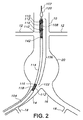
図1は、血管内プロテーゼ(図示せず)、例えばモジュール化グラフト組立体の実施形態の配備シーケンスの実施形態を示している。血管内方法に関し、患者の血管系への接近を達成するのに、動脈切開術を実施し、或いは患者の大腿動脈まで切開することによって若しくは他のありふれた技術、例えば経皮セルディンガー法によって実施するのが良い。かかる技術に関し、デリバリシース(図示せず)を拡張器・ガイドワイヤ組立体の使用により患者の血管、例えば大腿動脈の内部を連絡関係をなして配置するのが良い。デリバリシースをいったん位置決めすると、患者の血管系に対する接近をデリバリシースを介して達成することができ、デリバリシースは、オプションとして、止血弁又は他の適当な機構体によって封止するのが良い。幾つかの手順に関し、デリバリシースが患者の大動脈に向かって上流に方向付けされた状態で患者の両方の大腿動脈へのデリバリシース又は他の適当な手段による接近を得ることが必要な場合がある。幾つかの用途では、デリバリシースは不要な場合があり、本発明のデリバリカテーテルを動脈切開術か経皮穿刺かのいずれかによって患者の接近血管中に直接挿入するのが良い。1本又は複数本のデリバリシースを適切にいったん位置決めすると、代表的には血管内プロテーゼ、例えばインフレート可能なステント‐グラフト(これには限定されない)を収容した血管内デリバリカテーテル又はシステムをデリバリシースを通っているガイドワイヤ上でこれに沿って患者の血管系中に前進させるのが良い。 FIG. 1 illustrates an embodiment of a deployment sequence for an embodiment of an endovascular prosthesis (not shown), eg, a modular graft assembly. With respect to endovascular methods, to achieve access to the patient's vasculature, an arteriotomy is performed, or by incision into the patient's femoral artery or by other common techniques such as the percutaneous Seldinger method Good to do. With respect to such techniques, a delivery sheath (not shown) may be placed in communication with the patient's blood vessel, such as the femoral artery, by use of a dilator and guide wire assembly. Once the delivery sheath is positioned, access to the patient's vasculature can be achieved through the delivery sheath, which can optionally be sealed by a hemostasis valve or other suitable mechanism. For some procedures, it may be necessary to gain access to both the patient's femoral artery by delivery sheath or other suitable means with the delivery sheath oriented upstream toward the patient's aorta. . For some applications, a delivery sheath may not be necessary, and the delivery catheter of the present invention may be inserted directly into the patient's access vessel by either arteriotomy or percutaneous puncture. Once properly positioned, one or more delivery sheaths typically deliver an endovascular delivery catheter or system containing an endovascular prosthesis, such as but not limited to an inflatable stent-graft. It may be advanced along the guidewire passing therethrough and into the patient's vasculature.
図1は、患者の血管系内の本発明の血管内デリバリシステム100の当初の配置状態を示している。血管内デリバリシステム100をガイドワイヤ102に沿って血管の上流側に近位側へ前進させて、図1に示されている腸骨動脈14,16及び大動脈10を含む患者の血管系中に送り進めるのが良い。腸骨動脈14,16は、それぞれ、右及び左総腸骨動脈として医学的に説明される場合があるが、本明細書で用いられているように、腸骨動脈14は、同側腸骨動脈として説明され、腸骨動脈16は、対側腸骨動脈として説明される。患者の血液(図示せず)の流れは、図1では全体として下向きの方向である。図1に示された患者の血管系の他の血管としては、腎動脈12及び内腸骨動脈18が挙げられる。
FIG. 1 shows the initial placement of an
血管内デリバリシステム100を患者の大動脈10中に前進させるのが良く、ついには、血管内プロテーゼ(図示せず)が治療されるべき大動脈瘤20又は他の血管欠陥に実質的に隣接して配置されるようにする。体内管腔を通って送り進められる血管内デリバリシステム100の部分は、望ましくは、例えば全外径が14フレンチ未満の低プロフィールデリバリシステムである。他のフレンチサイズ、例えば12フレンチ未満、10フレンチ未満又は10〜14フレンチの任意のサイズも又有用であるが、これらには限定されない。血管内デリバリシステム100がいったんそのように位置決めされると、血管内デリバリシステム100の外側シース104を遠位側に引っ込めるのが良く、それにより血管内デリバリシステム100の外側シース104の内側ルーメン内に嵌まり込むよう圧縮されると共にコンパクトになったプロテーゼ(図示せず)が露出される。
The
図2に示されているように、血管内デリバリシステム100をそのようにいったん位置決めすると、血管内デリバリシステム100の外側シースを遠位側に引っ込めるのが良く、それにより血管内デリバリシステム100の外側シース104の内側ルーメン内に嵌まり込むよう圧縮されると共にコンパクトになった血管内プロテーゼ106が露出される。外側シース104は、人体に適合性のある材料で作られるのが良い。望ましくは、生体適合性材料は、生体適合性ポリマーであるのが良い。適当な生体適合性ポリマーの例としては、ポリオレフィン、例えばポリエチレン(PE)、高密度ポリエチレン(HDPE)及びポリプロピレン(PP)、ポリオレフィンコポリマー及びターポリマー、ポリテトラフルオロエチレン(PTFE)、ポリエチレンテレフタレート(PET)、ポリエステル、ポリアミド、ポリウレタン、ポリウレタンウレア、ポリプロピレン及びポリカーボネート、ポリビニルアセテート、ポリエステル‐ポリエステルブロックコポリマー及びポリアミド/ポリエーテル/ポリエステルエラストマーを含む熱可塑性エラストマー、ポリ塩化ビニル、ポリスチレン、ポリアクリレート、ポリメタクリレート、ポリアクリロニトリル、ポリアクリルアミド、シリコーン樹脂、これらの組み合わせ及びコポリマー等が挙げられるが、これらには限定されない。望ましくは、生体適合性ポリマーとしては、ポリプロピレン(PP)、ポリテトラフルオロエチレン(PTFE)、ポリエチレンテレフタレート(PET)、高密度ポリエチレン(HDPE)、これらの組み合わせ及びコポリマー等が挙げられる。有用な被覆材料としては、任意適当な生体適合性皮膜が挙げられる。適当な皮膜の非限定的な例としては、ポリテトラフルオロエチレン(PTFE)、シリコーン、親水性材料、ヒドロゲル等が挙げられる。有用な親水性被覆材料としては、アルキレングリコール、アルコキシポリアクリレングリコール、例えばメトキシポリ酸化エチレン、ポリオキシアルキレングリコール、例えばポリ酸化エチレン、ポリ酸化エチレン/ポリ酸化プロピレンコポリマー、ポリ酸化アルキレン改質ポリジメチルシロキサン、ポリフォスファゼン、ポリ(2‐エチル‐2‐オキサゾリン)、(メト)アクリル酸、ポリ(アクリル酸)のホモポリマー及びコポリマー、メチルビニルエーテル及びマレイン酸を含む無水マレイン酸のコポリマー、ポリ(ビニルピロリドン)ホモポリマー及びビニルピロリドン、ポリ(ビニルフルフォン酸)のコポリマーを含むピロリドン、ポリ(N‐アルキルアクリルアミド)、ポリ(ビニルアルコール)、ポリ(エチレンイミン)、ポリアミド、ポリ(カルボン酸)、メチルセルロース、カルボキシメチルセルロース、ヒドロキシプロピルセルロース、ポリビニルスルフォン酸、水溶性ナイロン、ヘパリン、デキストラン、改質デキストラン、ヒドロキシル化キチン、コンドロイチンスルフェート、レシチン、ヒアルラノン、これらの組み合わせ及びコポリマー等が挙げられるが、これらには限定されない。適当なヒドロゲル皮膜の非限定的な例としては、ポリ酸化エチレン及びそのコポリマー、ポリビニルピロリドン及びその誘導体、ヒドロキシエチルアクリレート又はヒドロキシエチル(メト)アクリレート、ポリアクリル酸、ポリアクリルアミド、ポリエチレン無水マレイン酸、これらの組み合わせ及びコポリマー等が挙げられる。望ましくは、外側シース104は、ポリマー材料、例えばポリイミド、ポリエステルエラストマー(Hytrel(登録商標))又はポリエーテルブロックアミド(Pebax(登録商標))、ポリテトラフルオロエチレン、及び他の熱可塑性樹脂及びポリマーで作られるのが良い。外側シース104の外径は、約0.1インチ(2.54mm)から約0.4インチ(10.16mm)の範囲にあるのが良い。外側シース104の壁圧は、約0.002インチ(0.051mm)から約0.015インチ(0.381mm)までの範囲にあるのが良い。外側シース104は、外側親水性皮膜を更に有するのが良い。さらに、外側シース104は、金属製かポリマー製かのいずれかのフィラメントの内側編組部分を有するのが良い。血管内デリバリシステム100の外側シース104の内側ルーメン内に配置されたときに半径方向に圧縮されることに加えて、近位ステント108は、高力可撓性ベルト110によって半径方向に拘束されるのが良く、その目的は、近位ステント108の配備が開始されるまで、小さなプロフィールを維持すると共に近位ステント108と体内管腔壁との係合を回避することにある。ベルト110は、ベルト部材の張力要件に対応することができると共に束縛形態で配置された後でも可撓性のままであることができる任意の高力弾性材料で作られるのが良い。代表的には、ベルト110は、形状記憶合金、例えばニッケルチタン等の中実リボン又はワイヤで作られるが、他の金属又はポリマー材料が使用可能である。ベルト110は、高力合成繊維、例えばダクロン(Dacron(登録商標))、Spectra等の編組金属フィラメント又は編組若しくは中実フィラメントで作られても良い。ベルト110の外側横方向断面寸法は、約0.002インチ(0.051mm)から約0.012インチ(0.305mm)までの範囲、特に、約0.004インチ(0.102mm)から約0.007インチ(0.178mm)までの範囲にあるのが良い。ベルト21,22,23の断面は、一般に、任意の形状を取って良く、かかる形状としては、長方形(リボンの場合)、円形、楕円形、正方形等が挙げられる。ベルト110の端は、1本又は2本以上のステントリリースワイヤ又は細長いロッド112によって固定されるのが良く、かかるワイヤ又はロッド112は、ベルト110のループ状端部(図示せず)を貫通して延びている。ステントリリースワイヤ又は細長いロッド112は、所望の体内場所へのシステム100の運搬中、全体がプロテーゼ106内に設けられるのが良い。例えば、ステントリリースワイヤ又は細長いロッド112は、ステント108の制御されたリリースに影響を及ぼすよう所望に応じてガイドワイヤルーメン122又は他のデリバリシステムルーメンに出入りするのが良く、かかる制御されたリリースとしては、所望ならば、ステント108について制御されると共にステージングされたリリースが挙げられる。血管内デリバリシステム100の外側シース104をいったん引っ込めると、血管内デリバリシステム100及び血管内プロテーゼ106を近位ステント108が腎動脈と実質的に同一高さに配置されるよう軸方向に注意を払って位置決めするのが良い。
As shown in FIG. 2, once the
望ましくは、血管内プロテーゼ106は、インフレート可能なグラフト114を有する。インフレート可能なグラフトは、メイングラフト本体124、同側グラフトレッグ及び対側グラフトレッグ128を有する二叉状のグラフトであるのが良い。インフレート可能なグラフト114は、インフレーション媒体(図示せず)を提供するために、血管内デリバリシステム100のインフレーションチューブと流体連通状態にある充填ポート116を更に有するのが良い。血管内デリバリシステム100の遠位部分は、血管内デリバリシステム100の無傷性遠位部分を提供するノーズコーン120を含むのが良い。ガイドワイヤ102は、血管内デリバリシステム100のガイドワイヤルーメン122内に摺動可能に設けられている。
Desirably, the
図3に示されているように、近位ステント108の配備は、ステント108の遠位部分130を拘束するベルト110の端部を結合しているステントリリースワイヤ又はロッド112を引っ込めることによってステント108の遠位部分130の配備で始まるのが良い。ステント108の遠位部分130は、コネクタリング142を介してメイングラフト本体124に対して設けられるのが良い。ステント108及び/又はコネクタリング142は、任意の生体適合性材料で作られるのが良く又はこれを含むのが良く、生体適合性材料としては、金属製の材料、例えばニチノール、コバルト基合金、例えばエルジロイ(Elgiloy)、白金、金、ステンレス鋼、チタン、タンタル、ニオブ及びこれらの組み合わせが挙げられるが、これらには限定されない。しかしながら、本発明は、かかるコネクタリング142の使用には限定されず、ステント108の遠位部分130をメイングラフト本体124の端部のところに又はその近くに固定するための他の形状のコネクタを適切に使用することができる。追加の軸方向位置決めは、代表的には、ステント108の遠位部分130を配備した後であっても実施できる。これは、多くの環境において、ステント108の近位部分132か幾つかの実施形態のために組織係合棘部(図示せず)を有しておらず、ステント108の近位部分132が配備されるまで患者の血管又は大動脈10の内側管腔に加わる部分的な外向きの半径方向接触又は摩擦力しか及ぼさないので依然として実施できる。ステント108の近位部分132を束縛するベルト110をいったんリリースすると、ステント108の近位部分132は、外向きの半径方向に自己拡張し、ついには、ステント108の近位部分132の外面が患者の血管10の内面に接触してこれに係合するようになる。
As shown in FIG. 3, deployment of the
図4に示されているように、ステント108の遠位部分130を配備した後、次に、ステント108の近位部分132を拘束しているベルト110の端部を結合しているワイヤ112を引っ込めることによってステント108の近位部分132を配備するのが良い。ステント108の近位部分132が外向きの半径方向に自己拡張すると、ステント108の近位部分132の外面は、最終的に、患者の大動脈10の内面に接触する。ステント108の近位部分132に設けられた組織係合棘部(図示せず)を有する実施形態の場合、棘部も又、外向きの半径方向に差し向けられると共に押されるのが良く、それにより患者の血管10の内面組織に接触してこれに係合し、それにより近位ステント108を患者の血管10に更に固定する。
As shown in FIG. 4, after deploying the
近位ステント108を患者の血管10の内面にいったん固定すると、次に、インフレーションポート116を介して、血管内デリバリシステム100のインフレーションチューブ118を通って注入されたインフレーション材料で近位インフレート可能カフ134を満たすのが良く、インフレーションチューブは、インフレート可能カフ134の外面を血管10の内面に密着させるのに役立つ場合がある。インフレート可能チャネル136の残りのネットワークも又、それと同時に加圧インフレーション材料で満たし、かかる加圧インフレーション材料は、インフレート可能グラフト114に対して剛性の高いフレーム状構造体を提供する。幾つかの実施形態に関し、インフレーション材料は、インフレート可能チャネル136のネットワークがネットワーク内で所望レベルの材料又は圧力までいったん満たされると、硬化可能又は固化可能な材料であるのが良い。幾つかの実施形態は、充填プロセスのモニタ及び次のグラフト延長部(図示せず)の係合を容易にするよう放射線不透過性インフレーション材料も又用いるのが良い。この材料は、本明細書において説明する適当な方法のうちの任意のものによって硬化可能であり、かかる方法としては、時間の経過、熱を加えること、電磁エネルギーを加えること、超音波エネルギーを加えること、化学薬品の添加又は混合等が挙げられる。インフレート可能カフ134又はインフレート可能チャネル136のネットワーク内から外向きの圧力又は剛性構造体を提供するために使用できるインフレーション材料に関する幾つかの実施形態としては、グリシジルエーテル及びアミン材料で作られたインフレーション材料が挙げられる。インフレーション材料に関する幾つかの実施形態は、第1の量のジアミン及び第2の量のポリグリシジルエーテルを含む現場成形ヒドロゲルポリマーを含むのが良く、これら量の各々は、哺乳動物又は生体適合性であり且つ混合後、約10秒〜約30分の硬化時間を有する現場生成ヒドロゲルポリマーを生じさせる量で哺乳動物内に配置された医療器具、例えば、インフレート可能グラフト中に存在し、ヒドロゲルポリマーの体積は、硬化及び水和後、30パーセント未満膨潤する。インフレート材料の幾つかの実施形態としては、放射線不透過性物質、例えばヨウ化ナトリウム、ヨウ化カリウム、硫酸バリウム、Visipaque 320、Hypaque、Omnipaque 350、Hexabrix等が挙げられる。インフレーション材料に関する幾つかの実施形態について、ポリグリシジルエーテルは、トリメチルオルプロパントリグリシジルエーテル、ソルビトールポリグリシジルエーテル、ポリグリセロールポリグリシジルエーテル、ペンタエリトリトールポリグリシジルエーテル、ジグリセロールポリグリシジルエーテル、グリセロールポリグリシジルエーテル、トリメチルオルプロパンポリグリシジルエーテル、ポリエチレングリコールグリシジルエーテル、レソルシノールジグリシジルエーテル、p‐ヒドロキシ安息酸のグリシジルエステルエーテル、ネオペンチルグリコールグリシジルエーテル、1,6‐ヘキサンジオールジグリシジルエーテル、ビスフェホールA(PO)2ジグリシジルエーテル、ヒドロキノンジグリシジルエーテル、ビスフェノールSジグリシジルエーテル、テレフタル酸ジグリシジルエーテル及びこれらの混合物から選択されるのが良い。インフレーション材料に関する幾つかの実施形態について、ジアミンは、ポリエチレングリコール(400)ジアミン、ジ‐(3‐アミノプロピル)ジエチレングリコールr、ポリオキシプロピレンジアミン、ポリエーテルジアミン、ポリオキシエチレンジアミン、トリエチレングリコールジアミン及びこれらの混合物から成る群から選択されたアミノ基又はアルキルアミノ基を有する(ポリ)アルキレングリコールから選択されるのが良い。幾つかの実施形態について、ジアミンは、親水性であるのが良く、ポリグリシジルエーテルは、硬化に先立って親水性であるのが良い。幾つかの実施形態に関し、ジアミンは、親水性であるのが良く、ポリグリシジルエーテルは、硬化に先立って疎水性であるのが良い。幾つかの実施形態について、ジアミンは、疎水性であるのが良く、ポリグリシジルエーテルは、硬化に先立って親水性であるのが良い。
Once the
メイン充填ポート116中への適当なインフレーション材料の注入によってインフレート可能チャネル136のネットワークを部分的に又は全体的にインフレートさせることができ、それにより剛性がインフレート可能チャネル136のネットワーク及びグラフト114にもたらされる。加うるに、シールがインフレート可能カフ134と腹部大動脈10の内面との間に作られる。配備プロセスのこの段階でグラフト114のインフレート可能チャネル136のネットワークを部分的に又は全体的にインフレートさせることが望ましいが、かかるインフレーションステップは、オプションとして、必要ならば後の段階で達成されても良い。
The
グラフト114をいったん定着させ、そしてそのインフレート可能チャネル136に充填してこれを拡張させると、別のデリバリカテーテル(図示せず)を用いて図5に示すように対側グラフト延長部138を配備することができる。対側グラフト延長部138は、グラフト114の対側レッグ128とオーバーラップする軸方向位置にある。グラフト延長部138と対側レッグ128の所望のオーバーラップ量は、血管形態学的特徴、血管疾患の程度、患者の状態等を含む種々の要因に応じて様々な場合がある。しかしながら、幾つかの実施形態の場合、対側グラフト延長部138と対側レッグ128の軸方向オーバーラップ量は、約1cm〜約5cm、特に約2cm〜約4cmであるのが良い。対側グラフト延長部138をいったん配備すると、同側グラフト延長部を同側グラフトレッグ126内に同様に配備することができる。
Once
幾つかの配備実施形態の場合、患者の内腸骨動脈は、内腸骨動脈が配備によって閉塞されないようにするための位置決め基準箇所として役立つよう使用できる。かかる配備の際、グラフト延長部138又は140の遠位端をグラフト114の同側レッグ126又は対側レッグ128の所与の長さ内のどこかの場所に配備することができる。また、グラフト組立体114の同側の側部及び対側の側部上に配備された状態でグラフト延長部140,138が1つしか示されていないが、同側レッグ126又は対側レッグ128について所望の長さの延長を達成するために追加のグラフト延長部140,138を既に配備されているグラフト延長部140,138内に配備するのが良い。幾つかの実施形態に関し、約1つ〜約5つのグラフト延長部138,140をグラフト組立体114の同側の側部か対側の側部かのいずれかに配備するのが良い。連続して位置するグラフト延長部138,140を互いの中に配備して連続して位置するグラフト延長部の流体流れルーメンを長手方向にオーバーラップさせるのが良い。
For some deployment embodiments, the patient's internal iliac artery can be used to serve as a positioning reference point to prevent the internal iliac artery from being occluded by the deployment. During such deployment, the distal end of the
幾つかの実施形態については互換性があるグラフト延長部138,140又はメイングラフト部分124の任意他の適当な延長器具若しくは部分は、種々の適当な形態を有して良い。幾つかの実施形態に関し、グラフト延長部138,140は、螺旋ニチノールステント144を備えたポリテトラフルオロエチレン(PTFE)グラフト142を含むのが良い。
The
血管内プロテーゼ106及び/又はグラフト延長部138,140に関するそれ以上の詳細は、共通譲受人の米国特許第6,395,019号明細書、同第7,081,129号明細書、同第7,147,660号明細書、同第7,147,661号明細書、同第7,150,758号明細書、同第7,615,071号明細書、同第7,766,954号明細書及び同第8,167,927号明細書並びに共通譲受人の米国特許出願公開第2009/0099649号明細書に見受けられ、これら特許文献の全てを参照により引用し、これらの記載内容全体を本明細書の一部とする。血管内プロテーゼ106の製造に関する詳細は、共通譲受人の米国特許第6,776,604号明細書、同第7,090,693号明細書、同第7,125,464号明細書、同第7,147,455号明細書、同第7,678,217号明細書及び同第7,682,475号明細書に見受けられ、これら特許文献の全てを参照により引用し、これらの記載内容全体を本明細書の一部とする。インフレート可能グラフト114に関する有用なインフレーション材料は、共通譲受人の米国特許出願公開第2005/0158272号明細書及び同第2006/0222596号明細書に見受けられ、これら特許文献の全てを参照により引用し、これらの記載内容全体を本明細書の一部とする。二叉になっていて且つインフレート可能なプロテーゼの同側レッグに対する対側レッグの動きを拘束するために同側レッグからのテザーを有するかかる二叉のインフレート可能なプロテーゼを有する血管内デリバリシステムの追加の詳細が2012年6月15日に出願された共通譲受人の米国特許仮出願第61/660,105号明細書(発明の名称:Bifurcated Endovascular Prosthesis Having Tethered Contralateral Leg、代理人事件番号1880‐44P)に見受けられ、この特許文献を参照により引用し、その記載内容全体を本明細書の一部とする。改良型ハイポチューブを含む血管内デリバリシステムの追加の詳細が2012年6月15日に出願された共通譲受人の米国特許仮出願第61/660,103号明細書(発明の名称:Endovascular Delivery System With Flexible And Torqueable Hypotube、代理人事件番号1880‐43P)に見受けられ、この特許文献を参照により引用し、その記載内容全体を本明細書の一部とする。
For further details regarding
血管内プロテーゼ106に有用なグラフト材料としては、ポリエチレン、ポリプロピレン、ポリ塩化ビニル、ポリテトラフルオロエチレン(PTFE)、フッ化エチレンプロピレン、フッ化エチレンプロピレン、ポリビニルアセテート、ポリスチレン、ポリ(エチレンテレフタレート)、ナフタレンジカルボキシレート誘導体、例えばポリエチレンナフタレート、ポリブチレンナフタレート、ポリトリメチレンナフタレート及びトリメチレンジオールナフタレート、ポリウレタン、ポリウレア、シリコーンゴム、ポリアミド、ポリイミド、ポリカーボネート、ポリアルデヒド、ポリエーテルエーテルケトン、天然ゴム、ポリエステルコポリマー、シリコーン、スチレン‐ブタジエンコポリマー、ポリエーテル、例えば完全又は部分ハロゲン化ポリエーテル、これらのコポリマー及び組み合わせが挙げられるが、これらには限定されない。望ましくは、グラフト材料は、テキスタイルグラフトと併用可能なノンテキスタイルグラフト材料、例えば織編されておらず、編組されておらず、フィラメント紡糸されていない等の材料である。かかる有用なグラフト材料は、押し出し材料であるのが良い。特に有用な材料としては、識別可能な節及びフィブリル微細構造がなく、しかも結晶粒界が隣接の高密度領域の結晶粒界に直接相互連結された高密度領域を有すると共に実質的に節及びフィブリル微細構造のない独立気泡微細構造を含む流体透過性が低い又は実質的にゼロである(湿潤)延伸PTFE層のない多孔質ポリテトラフルオロエチレン及び流体透過性がゼロであり又は実質的にゼロである多孔質PTFEが挙げられる。ePTFEの隣接の節を相互に連結している明確な互いに平行なフィブリルを欠いているPTFE層は、20,000倍の走査型電子顕微鏡(SEM)で見て識別可能な節及びフィブリル微細構造を備えていない。流体透過性がゼロであり又は実質的にゼロである多孔質PTFE層は、約12時間以上のガーレ数又は本質的に無制限の又は大きすぎて測定することができないガーレ数を有する場合があり、このことは、測定可能は流体透過性がゼロであることを示している。流体透過性が実質的にゼロであるPTFE層の中には、100ccの空気で約106秒以上のガーレ数を有するものがある。ガーレ秒数は、所与の量、代表的には25cc、100cc又は300ccの空気が標準圧力、例えば水柱12.4cm下で材料又はフィルムの標準1平方インチを通って流れるのに必要な時間を測定することによって求められる。かかる試験は、ニューヨーク州トロイ所在のガーレ・プレシジョン・インストゥルメンツ(Gurley Precision Instruments)製のGurley Densometerを用いて実施できる。かかる有用なPTFE材料及びこれを製造する方法の詳細は、共通譲受人の米国特許出願公開第2006/0233991号明細書に見受けられ、この特許文献を参照により引用し、その記載内容全体を本明細書の一部とする。
Useful graft materials for the
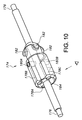
図6は、本発明の血管内デリバリシステム100の側面図である。血管内デリバリシステム100は、とりわけ、ノーズコーン120、外側シース104、外側シース104のための引っ込めノブ又はハンドル152、外側シース104のためのフラッシュポート154、外側シース放射線不透過性マーカバンド156、内側管状部材150、インフレーション材料又はポリマー充填コネクタポート158、インフレーション材料又はポリマー充填キャップ160、ガイドワイヤフラッシュポート162、ガイドワイヤフラッシュポートキャップ164、ガイドワイヤポート166、及び入れ子式ステントリリースノブ168を含み、これら図示のように相互に関連付けられている。
FIG. 6 is a side view of the
外側シース104のためのフラッシュポート154は、運搬段階中、外側シース104をフラッシングするために使用できる。外側シース104は、担当医がデリバリシステム100を所望の体内部位まで適切にナビゲートするのを助ける放射線不透過性マーカバンドを有するのが良い。外側シース104は、担当医が外側シース104のための引っ込めノブ又はハンドル152をデリバリシステム100の近位ハンドル組立体170に向かって動かすことによって引っ込み可能である。内側管状部材150は、内側管状部材150から見てデリバリシステム100の近位部分寄りに設けられている。インフレーション材料又はポリマー充填コネクタポート158及びインフレーション材料又はポリマー充填キャップ160は、インフレート可能グラフト114の近位インフレート可能カフ134及びインフレート可能チャネル136のネットワークをインフレートさせるようインフレーション材料又はポリマー充填材料を提供する上で有用である。ガイドワイヤフラッシュポート162及びガイドワイヤフラッシュポートキャップ164は、デリバリシステム100の運搬段階中、ガイドワイヤポート166をフラッシングする上で有用である。入れ子式ステントリリースノブ168は、血管内プロテーゼ106の運搬のためのリリース機構体に係合するために用いられる一連の入れ子式ノブ(図示せず)を含む。血管内プロテーゼの配備のための方法、カテーテル及びシステムを含む(これらには限定されない)それ以上の詳細が共通譲受人の米国特許第6,761,733号明細書及び同第6,733,521号明細書並びに共通譲受人の米国特許出願公開第2006/0009833号明細書及び同第2009/0099649号明細書に開示されており、これら特許文献を引用し、これらの記載内容全体を本明細書の一部とする。
A
図7は、本発明の血管内デリバリシステム100の遠位部分172の側面部分切除図であり、図8は、本発明の血管内デリバリシステム100の遠位部分172の部分斜視部分切除図である。血管内デリバリシステム100の遠位部分172は、プロテーゼ/ステントホルダガイドワイヤ176に装着されたプロテーゼ/ステントホルダ174を有している。ホルダ174は、血管内プロテーゼ106(図示せず)をデリバリシステム100内にリリース可能に固定する上で有用である。ホルダ174は、デリバリシステム100の運搬段階中、血管内プロテーゼ106の望ましくない長手方向及び/又は円周方向運動を阻止し又は実質的に阻止する。ベルト110は、血管内プロテーゼ106の望ましいリリースまで血管内プロテーゼ106を半径方向束縛段階に拘束するのに役立つ。
FIG. 7 is a side cutaway view of the
プロテーゼ106の運搬中、器具を植え込む医師は、一連の放射線不透過性マーカを用いてプロテーゼを適正な場所に整列させながら器具を患者の体内に挿入することになる。しかしながら、代表的なデリバリ器具は、体内への器具の適正な配置を助けるようプロテーゼそれ自体に設けられた放射線不透過性マーカを用いる場合がある。プロテーゼそれ自体への放射線不透過性マーカの使用は、かかる放射線不透過性マーカの識別及び区別を困難にする幾つかのプロテーゼの固有の放射線不透過性に起因して不十分な場合がある。
During delivery of the
図9は、放射線不透過性であるのが良い2つのマーカ200,202を含む本発明の実施形態の利点を実証している。図9は、ガイドワイヤ176の長手方向軸線に沿うプロテーゼデリバリ器具の概略断面図であり、第1のマーカ200及び第2のマーカ202を示している。この実施形態を用いたプロテーゼの運搬中、デリバリ器具を植え込む医師は、代表的には、X線透視法によりマーカ200,202を含むプロテーゼ及びそのデリバリシステムの1つ又は2つ以上の画像を観察し、X線透視法は、図9において視線の描写図で分かるようにデリバリシステム及びガイドワイヤ176の長手方向軸線に全体として垂直の遠近法的見方から見たデリバリシステムの画像を提供する。図9に概略的に示されているように、視線の方向は、軸線yに沿っている。ガイドワイヤ176は、放射線不透過性材料で作られるのが良い。理解できるように、y軸線に沿う図における投影図で見て、第1のマーカ200と第2のマーカ202との間に隙間が存在する。ユーザの視線と完全な軸方向/回転位置合わせ状態では(即ち、図9で見てマーカ200又は202とx軸線又はy軸線かのいずれかとのなす角度として定められた回転角度θはがゼロであると定められている場合)、隙間204は、その最大の状態にある。図9で理解できるように、器具をこの位置から遠ざかるようにガイドワイヤ175の長手方向軸線に沿って回転させると、隙間204は、小さくなる。各マーカ200,202の半径方向離隔距離(マーカ202の場合、この半径方向離隔距離は、ガイドワイヤ176から最も外側の部分まで測定した半径方向離隔距離である)は、記号“R”で示されている。第1のマーカ200と第2のマーカ202との間の隙間204は、Rcosθ−Rsinθで示されている。特に、第2のマーカ202が存在しない場合、隙間は、Rcosθとして示される(ガイドワイヤ176の幅の僅かな効果を無視するものとする)。
FIG. 9 demonstrates the advantages of an embodiment of the present invention that includes two
医師が意図したθ=0位置でプロテーゼの最も正確な所望の回転/円周方向位置合わせ状態を達成することがするため、隙間204は、できるだけ大きいのが良い。かくして、プロテーゼの運搬中、器具を植え込む医師は、マーカ相互間の隙間がその最大の状態になるまでプロテーゼを回転させるのが良い。個人の体内の血管本体は、ガイドワイヤ176の軸線に沿って又は別法としてカテーテルルーメンの軸線に沿って完全な対称性を有しているわけではなく、血管プロテーゼは、それに応じて構成されるのが良い。したがって、これら血管本体内へのプロテーゼの配置は、精密且つ正確な回転位置合わせ状態、即ちその長手方向軸線に沿って円周方向における器具の位置合わせを必要とする場合がある。ほんの僅かな位置合わせ不良が存在しても、その結果として、血管本体内への不完全な配置が生じる場合があり、或いは運搬手技が複雑になると共に/或いは長くなる場合があり、その結果、かかる手技と関連した有害な臨床上の出費及び/又はコストの増大が生じる場合がある。例えば、対側リム孔(ゲート)のカニューレ挿入は、器具が正しく差し向けられない場合、悪影響を受ける場合がある。例えば、器具の適正な向きにより、大動脈本体リムを側方に位置決めすることができ、それにより患者の対側アクセス血管中に挿入されたガイドワイヤ/カテーテルを介する対側ゲートへの接近が容易になる。
The
図9に示されている実施形態の第2のマーカ202に関し、カテーテルの回転角度の関数としての隙間204の変化率を次式の「隙間方程式」として表すことができ、即ち、
dgap/dθ=−R(sinθ+cosθ)
であり、他方、本明細書において説明した実施形態において構成される第2のマーカのないシステムの場合、隙間の変化率は次式で表される。
dgap/dθ=−Rsinθ
For the
d gap / dθ = −R (sin θ + cos θ)
On the other hand, in the case of a system without the second marker configured in the embodiment described in this specification, the change rate of the gap is expressed by the following equation.
d gap / dθ = −R sin θ
幾つかの実施形態に関し、プロテーゼ106が最適配置状態が得られるよう正しく位置決めされると(θは、ほぼゼロである)、dgap/dθは、約−Rであり、比較的大きい値である(この値は、回転角度の関数として隙間の幅に対して強い感度を示している)(これとは対照的に、単一のマーカを有するシステムの場合、dgap/dθ=0であり、即ち、回転角度θに対する隙間204の幅の変化又は感度は、存在しない)。小さな角度の誤差が存在する場合に関し、例えば、θが約0.1ラジアン(約6°回転させた場合)、dgap/dθは、単一のマーカケースを含むシステムと比較して2つのマーカを有する実施形態では約11倍である。
For some embodiments, when the
したがって、幾つかの実施形態は、少なくとも1つ、望ましくは2つの追加のマーカを有し、かかるマーカは各々、ガイドワイヤ176の長手方向軸線から測定して第1のマーカからほぼ±90°の角度のところに位置する。図は、軸方向に整列した管状マーカを示しているが、有用なマーカは、器具の中心から放射状に延びる単にドット、正方形又はバーであるのが良い。望ましくは、これらマーカは、軸線(及びかくしてガイドワイヤ)とマーカとの間の隙間を最大にするためにできる限り器具の中心から遠ざかるように差し向けられる。各々が上述したように第1のマーカに対して約90°だけオフセットした2つ又は3つのかかるマーカを用いる実施形態では、隙間に対する回転感度の11倍以上の回転感度がプロテーゼを植え込む医師に与えられる場合があり、かくして、植え込み中、プロテーゼの位置合わせにおける著しく高い制御が可能である。かかる実施形態は、上記において概要を説明したように単一のマーカを有するシステムに関する問題を解決し又は軽減している。というのは、追加のマーカが約90°だけオフセットしているので、マーカのうちの少なくとも1つがプロテーゼ植え込み手順中、高い回転角度感度に寄与する位置に常時位置することになるからである(即ち、「隙間方程式」中のsinθかcosθかのいずれかの項が有効になるからである)。これにより、医師は、プロテーゼの植え込み中における向上したプロテーゼ配置感度を得ることができ、特に植え込み手技中、回転操作を実施する際の向上した配置感度を得ることができる。
Accordingly, some embodiments have at least one, and preferably two additional markers, each such marker approximately ± 90 ° from the first marker as measured from the longitudinal axis of the
改良型放射線不透過性マーカシステムは、ユーザがプロテーゼを正確に運搬する上で有用な場合がある。器具は、以下に説明するように一連のマーカを有するのが良い。以下の説明は、デリバリシステムの一コンポーネント、特にプロテーゼホルダに設けられた一連のマーカに関する。しかしながら、理解されるように、本明細書において説明するマーカシステムは、例えばシース又はノーズコーンを含むデリバリシステムの任意の部分で有用であると言える。加うるに、デリバリシステムは、マーカシステムを有する別個のコンポーネントを含むことができ、この別個のコンポーネントの目的は、マーカシステムをデリバリシステムに提供することにある。 An improved radiopaque marker system may be useful for the user to accurately carry the prosthesis. The instrument may have a series of markers as described below. The following description relates to a component of the delivery system, in particular a series of markers provided on the prosthesis holder. However, as will be appreciated, the marker systems described herein may be useful in any part of the delivery system including, for example, a sheath or nose cone. In addition, the delivery system can include a separate component having a marker system, the purpose of which is to provide the marker system to the delivery system.
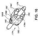
図10〜図17は、本明細書で説明している改良型放射線不透過性マーカシステムの実施形態を示している。図10は、このシステムのコンポーネントのそれぞれの後側及び前側から見た斜視図である。プロテーゼ/ステントホルダガイドワイヤ176がプロテーゼ/ステントホルダ174に設けられた中央ルーメン184を貫通しており、かくしてこの上に構成されているときにガイドワイヤ176の長手方向軸線と一致するルーメン184の長手方向軸線が形成されている。さらに、図10に示されている実施形態では、プロテーゼ/ステントホルダガイドワイヤ176は、プロテーゼ/ステントホルダガイドワイヤがプロテーゼ/ステントホルダ174の各端部のところで露出されるようプロテーゼ/ステントホルダルーメン184を完全に貫通して延びている。
10-17 illustrate embodiments of the improved radiopaque marker system described herein. FIG. 10 is a perspective view of the components of the system as viewed from the rear and front. A prosthesis / stent
ガイドワイヤ176は、任意所望の材料で構成できる。一実施形態では、ガイドワイヤ176は、X線撮影法、X線透視検査法又は他の視覚化技術により観察可能な材料で作られている。例えば、かかる材料は、金属、例えばパラジウム、イリジウム、金、タンタル、タングステン、白金及びこれらの組み合わせであるのが良い。材料は、ポリマー材料、例えば放射線不透過性ナイロンであっても良い。変形例として、材料は、放射線不透過性の充填剤、例えばビスマス、バリウム及びタングステンを含んでも良い。本発明は、ガイドワイヤ176を用いてプロテーゼの配置を助けることを想定しているが、最初の配置のためにガイドワイヤ176を用いることは、オプションである。すなわち、ガイドワイヤ176を引っ込めても良く又は全く用いなくても良く、プロテーゼ/ステントホルダ174に設けられたマーカは、プロテーゼの適正な回転位置合わせに関して誘導手段となるよう使用できる。
図10に示されている実施形態のプロテーゼ/ステントホルダ174の本体内には、一連の3つの軸方向に整列したマーカ178A,178B,178Cが設けられており、これらマーカは、軸方向ガイドワイヤ176によって形成された軸線に対して全て平行である。3つの軸方向に整列したマーカ178A,178B,178Cが全体として円筒形であるものとして図示されているが、理解されるように、任意適当なマーカを用いることができ、かかるマーカとしては、例えば、ドット若しくは一連のドット又はバーが挙げられる。3つの軸方向に整列したマーカ178A,178B,178Cは、プロテーゼ/ステントホルダガイドワイヤ176から適当な既知の距離だけ離隔した状態でプロテーゼ/ステントホルダ174の周囲周りに約90°間隔で配置されている。3つの軸方向に整列したマーカ178A,178B,178Cは、幾つかの実施形態では、各々同一長さ及び同一直径のものであるが、寸法設定において幾分かのばらつきが生じても良い。さらに、3つの軸方向に整列したマーカ178A,178B,178Cの各々は、プロテーゼ/ステントホルダガイドワイヤ176から同一距離だけ離隔しており、かくしてこれらの間に同一サイズの隙間が生じている。
Within the body of the prosthesis /
マーカ178A,178B,178Cは、配備手技で用いられる画像化モダリティにより目に見える任意所望の材料で構成でき、かかる材料としては、放射線不透過性材料、例えば白金、イリジウム、パラジウム、金、タンタル、タングステン、放射線不透過性ナイロン、ビスマス、バリウム、タングステン又はこれらの組み合わせが挙げられる。幾つかの実施形態では、3つの軸方向に整列したマーカ178A,178B,178Cの各々は、同一材料で作られ、但し、このことが必要であるというわけではない。特定の一実施形態では、マーカ178A,178B,178Cは、90重量%の白金及び10重量%のイリジウムの組み合わせで作られている。マーカ178A,178B,178Cは、同一形状のものであっても良く、異なる形状のものであっても良く、又、図10に示されているように円形であっても良いが、マーカのうちの1つ又は2つ以上について任意他の適当な対称又は非対称の形状を用いても良く、かかる形状としては、例えば、直角プリズム、バー、立方体、球体、分割筒体及び半月形状が挙げられる。マーカ178A,178B,178Cのうちの1つ又は2つ以上は、中空構造のものであっても良く、部分的に中空構造のものであっても良く、中実構造のものであっても良い。加うるに、互いに固定された別々の要素を有する1つの物理的マーカが設けられても良く、これら別々の要素は、これら要素相互間に隙間を形成するよう互いに間隔を置いて配置される。加うるに、互いに約90°の間隔を置いて設けられる少なくとも2つの要素が存在する限り、4つ以上のマーカが設けられても良い。例えば、器具に5つ又は6つ以上のマーカが設けられても良い。加うるに、マーカは、器具の回転時に隙間186を観察することができるようにする一連の不連続マーカ、例えば球体又は立方体が設けられても良い。
ガイドワイヤ176を用いる実施形態では、プロテーゼ/ステントホルダガイドワイヤ176の直径D176は、3つの軸方向に整列したマーカ178A,178B,178Cの各々の直径D178A,D178B,D178C以上であるのが良い。かくして、植え込み中、器具がその意図した横方向観察方向に対して適正に位置合わせされた場合、2つの側に位置する軸方向に整列したマーカ178A,178Cは、ガイドワイヤ176と一緒に視覚的に重ね合わされることになり、同一直線上に位置するマーカ178A,178Cと中央のマーカ178Bとの間には最大隙間が見えることになる。幾つかの実施形態では、プロテーゼ/ステントホルダガイドワイヤ176の直径は、約0.010インチ(0.254mm)から約0.060インチ(1.524mm)まで又は約0.030インチ(0.762mm)から約0.050インチ(1.270mm)までであるのが良く、3つの軸方向に整列したマーカ178A,178B,178Cの各々の直径は、約0.010インチ(0.254mm)から約0.060インチ(1.524mm)まで又は約0.020インチ(0.508mm)から約0.030インチ(0.762mm)までである。
In embodiments using a
プロテーゼ/ステントホルダ174は、オプションとして、放射線不透過性であるのが良く且つ軸方向長さがプロテーゼ/ステントホルダガイドワイヤ176の軸線に対してほぼ90°(垂直)である方向に沿うように配置された1つ又は2つ以上のマーカ180A,180Bを有するのが良い。これらマーカ180A,180Bは、3つの軸方向に整列したマーカ178A,178B,178C及び/又はプロテーゼ/ステントホルダガイドワイヤ176と同一の材料で作られても良く、或いは、異なる放射線不透過性材料で作られても良い。マーカ180A,180Bは、形状が円筒形であるのが良いが、マーカ178A〜178Cについて説明したように任意所望の形状のものであっても良い。マーカ180A,180Bを設けることは、オプションである。というのは、これらは、人工器具の位置合わせを一段と助けるからである。
The prosthesis /
プロテーゼ/ステントホルダ174は、図10〜図17に示されている実施形態では、植え込み前及び植え込み中、プロテーゼ/ステントを定位置に固定する一連のクラウンアンカ182を有する。人工ステント(図示せず)のクラウンは、クラウンアンカ182の周りに固定されるのが良く、かくして植え込み前及び植え込み中におけるステントの回転運動が阻止される。プロテーゼ/ステントホルダ174及びクラウンアンカ182は、医師が植え込み中、放射線不透過性マーカ及びガイドワイヤ176を容易に視覚化することができるようにする任意所望の材料で構成でき、かかる材料としては、非放射線不透過製材料が挙げられる。
The prosthesis /
マーカ178A,178B,178C,180A,180Bは、任意適当な手段によって形成されてシステム中に組み込み可能である。マーカのうちの1つ又は2つ以上は、プロテーゼ/ステントホルダ174中に圧力嵌めされるのが良く、変形例として、マーカのうちの1つ又は2つ以上は、プロテーゼ/ステントホルダ174中に成形され、これらがホルダ174を構成する材料内に全体的に又は部分的に封入されるようにする。幾つかの実施形態では、マーカのうちの1つ又は2つ以上は、圧力嵌めされると共に適当な接着剤、例えばUV又はシアノアクリレート系接着剤により固定されるのが良い。
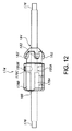
図11は、図10に示された実施形態のプロテーゼ/ステントホルダ174の側面図である。図11の側面図は、マーカ178A,178Cの長手方向軸線をガイドワイヤ176の長手方向軸線がホルダ174のルーメン184内に配置された状態でオーバーラップした状態で視覚的に整列させる観察角度で見た図である。この図は、例えば、例えばX線透視検査下でプロテーゼを血管系内に植え込む際に医師に見える図であるのが良い。この実施形態の特徴を説明する目的上、これを図10及び図13に示されているユーザの視線に対してプロテーゼ/ステントホルダ174の回転が行われないベースライン形態であるとみなす(即ち、θはゼロである)。
FIG. 11 is a side view of the prosthesis /
図11では、第2の軸方向に整列したマーカ178Bの外面又は外周とプロテーゼ/ステントホルダガイドワイヤ176の表面との間に隙間186が見える。ユーザが軸線yの視線に沿って見た隙間186の投影像は、ガイドワイヤ176の外面又は外周と第2の軸方向に整列したマーカ178Bの外面との間で測定される。上述したように、例えばX線透視による視覚化法下におけるプロテーゼ植え込み手技中、システムを隙間186のこの投影像が最大となるように回転させると、医師は、プロテーゼが所望の回転位置合わせ状態であるということができる。また、理解できるように、器具を図11に示されているように回転させると、マーカ178A,178Cは、プロテーゼ/ステントホルダガイドワイヤ176と視覚的に整列し、その結果、これらが大部分又は完全に互いにオーバーラップするようになる。この場合、X線透視検査下では、マーカ178A,178Cは、この整列状態では用追いには見えない。というのは、ガイドワイヤ176は、この特定の実施形態では、マーカ178A,178Cよりも幅が広いからである。
In FIG. 11, a
図11に示されている回転形態では、隙間186は、その最も大きな状態にある。この形態においてユーザに見える隙間186は、できるだけ大きいのが良く、これは、用いられるカテーテルのサイズで決まる。隙間186を最大にするため、マーカの直径D178は、依然としてユーザが画像化装置を介してマーカ178を観察することができる状態でできるだけ最小限に保たれるのが良い。マーカ178の構成材料の放射線不透過性が極めて高い場合、小さい又は薄いマーカ178を用いることができ、かかるマーカは、依然としてユーザに画像化装置によって可視性を与えることができる。放射線不透過性マーカ178の直径は、約0.010インチ(0.254mm)から約0.050インチ(1.270mm)又は約0.020インチ(0.508mm)から約0.040インチ(1.016mm)までであるのが良い。例えば、カテーテルの半径に応じて、隙間のサイズは、約0.010インチ(0.254mm)から約0.080インチ(2.032mm)までであるのが良い。代表的なプロテーゼシステム、例えば本明細書において説明しているプロテーゼシステムのための隙間空間は、約0.020インチ(0.508mm)から約0.065インチ(1.651mm)まで又は約0.035インチ(0.889mm)から約0.055インチ(1.397mm)までであるのが良い。しかしながら、これよりも大きな隙間を用いると、性能の低い画像化システム又は放射線不透過性の低い材料を用いた場合でもユーザが容易に見えることができるようにする。
In the rotational mode shown in FIG. 11, the
図12は、ガイドワイヤ176の長手方向軸線回りに約10°時計回りに回転させた図11のシステムを示している。理解できるように、マーカ178A,178B,178Cは、今や全て時計回りに回転してある。今や、マーカ178Cの一部分は、ガイドワイヤ176の境界部又は外面よりも僅かに上方に延びた状態で例えばX線透視検査下においてこの図で見える。同様に、マーカ178Aの一部分は、この図では、今や、ガイドワイヤ176の境界部又は外面よりも僅かに下に延びるものとして見える。マーカ178Bは、今や、隙間186の長さが今や図11の直接的な位置合わせ状態におけるその長さに対して小さいので、この角度で見てガイドワイヤ176の近くに位置するように見える。第1の軸方向に整列したマーカ178Aと第2の軸方向に整列したマーカ178Bの両方の存在により、隙間186は、プロテーゼ/ステントホルダ174の回転が僅かであっても大きな影響を受ける。単一のマーカ又は異なる形態を備えたシステムと比較して器具の回転中における隙間186のサイズのこの大幅な減少により、植え込み中における精度を高くすることができる。加うるに、3つのマーカ178A,178B,178Cの使用により、器具が時計回りに回されようと反時計回りに回されようと隙間186を最小限に抑えることができる。
FIG. 12 shows the system of FIG. 11 rotated about 10 ° clockwise about the longitudinal axis of
図13は、プロテーゼ/ステントホルダ174がその長手方向軸線及びそのルーメン184の長手方向軸線並びにガイドワイヤ176の同軸の長手方向軸線(紙面から出る垂直方向に延びる)に対して横方向に位置した状態の図である。理解できると共に図10を参照して上述したように、ガイドワイヤ176は、プロテーゼ/ステントホルダ174のルーメン184を貫通している。また、上述したように3つの軸方向に整列したマーカ178A,178B,178Cは、ガイドワイヤ176周りに設けられており、これらマーカは、約90°間隔で且つガイドワイヤ176から等しい距離を置いて互いに間隔を置いて設けられるのが良い。図11及び図12を参照して説明した隙間186の投影像も又示されている。
FIG. 13 shows the prosthesis /
図14は、上から見たプロテーゼ/ステントホルダ174を示し、図15は、下から見たプロテーゼ/ステントホルダ174を示している(両方とも、図13のコンポーネントの向きに対して見てである)。特に、下から見た場合、直接的な整列状態では、真ん中のマーカ178Bは、例え放射線不透過性であっても、これが放射線不透過性ガイドワイヤ176によって見えないようになっているので、例えばX線透視検査下において配備を行う医師によって視覚化するのが困難であり又は不可能である。
FIG. 14 shows the prosthesis /
図16及び図17はそれぞれ、プロテーゼ/ステントホルダ174を僅かに回転させた後における前から見た斜視図及び側面図である。理解できるように、ガイドワイヤ176の表面と軸方向に整列したマーカ178A,178B,178Cの表面とのなす角度及びこれらにより形成される隙間は、プロテーゼ/ステントホルダ174の回転に起因して変化する。
16 and 17 are a front perspective view and a side view, respectively, after the prosthesis /
図18は、実施形態としてのプロテーゼ/ステントホルダ174をその長手方向軸線回りに回転させたときの回転角度に応じたガイドワイヤ176と軸方向に整列したマーカ178A,178B又は178Cとの間の隙間186の変化を示すグラフ図である。グラフ図は、同一回転中におけるたった1つの軸方向に整列したマーカ(例えば、178B)を用いた器具中の同一に構成された隙間の変化と比較した場合の隙間(3つの軸方向に整列したマーカ178A,178B,178Cを用いた場合)の変化を示している。理解できるように、本発明の設計では、隙間186のサイズは、回転角度が所与の場合、1つのマーカを用いた器具の場合よりも大きな割合で減少している。隙間186を視覚化においてほぼゼロまで減少させるためには、プロテーゼ/ステントホルダ174を約22°回転させる必要があるだけである。しかしながら、軸方向整列マーカを1つしか用いない器具では、プロテーゼ/ステントホルダを約50°回転させる必要がある。かくして、本発明の設計は、他の器具よりも回転中、著しく高い正確さを提供する。マーカ178A,178B,178Cについて任意の形状又はレイアウトを用いることができ、かかるマーカとしては、上述したように、連続したマーカ、例えば筒体又は不連続マーカ、例えば一連のドット、球体、立方体等が挙げられる。加うるに、一実施形態では、同一の器具に互いに異なる形状のマーカを用いることができ、これによりユーザは、器具内のマーカを識別することができると共に高い精度の実現が可能である。例えば、マーカ178Aは、一連の球体としてのドットであるのが良く、マーカ178Cは、一連の立方体であるのが良い。器具を回転させて相対的なマーカ178A,178Cがユーザによって見えるようにすることができると、形状の差によりユーザは、一層高い制御及び精度を得ることができる。
FIG. 18 shows the gap between the
本発明は、任意所望の器具を運搬するよう使用でき、かかる器具としては、ステント、ステントグラフト等が挙げられる。本発明を用いて二叉の且つ有窓の器具を植え込むことができる。かかる器具は、他の場所での器具の配置を助けるために使用でき、かかる場所としては、例えば、頭蓋植え込みが挙げられる。さらに、本発明は、サイドアングルから見た場合の位置合わせを助ける上で極めて有用であるが、かかる器具は又、軸方向又は疑似軸方向図において位置合わせを提供する上で有用な場合がある。器具の種々の要素は、互いに異なる角度から見て回転時に角度及び隙間を作り、かくして、本発明は、種々の他の実施形態で有用な場合がある。 The present invention can be used to carry any desired device, such devices include stents, stent grafts and the like. The present invention can be used to implant bifurcated and windowed instruments. Such a device can be used to assist in placement of the device elsewhere, such as, for example, skull implantation. Furthermore, while the present invention is extremely useful in assisting alignment when viewed from a side angle, such an instrument may also be useful in providing alignment in an axial or pseudo-axial view. . Various elements of the instrument create angles and gaps when rotated from different angles, thus the present invention may be useful in various other embodiments.
本発明の器具をプロテーゼ/ステントホルダ174と関連して説明したが、注目されるように、本明細書において説明した軸方向に整列したマーカシステムは、デリバリ器具の他の場所及び他のコンポーネントにおいて有用な場合がある。
Although the device of the present invention has been described in connection with the prosthesis /
一実施形態では、上述したプロテーゼ/ステントホルダ174を含む植え込みのための器具が調製され、ステント‐グラフトプロテーゼがかかるプロテーゼ/ステントホルダ174に固定される。ステント‐グラフトプロテーゼは、上述したようにプロテーゼ/ステントホルダ174に固定され、デリバリ器具は、植え込みのために準備される。
In one embodiment, an implantable device is prepared that includes the prosthesis /
幾つかの実施形態では、プロテーゼを運搬すると共に植え込む方法が提供される。この実施形態では、上述したプロテーゼ/ステントホルダ174を含むデリバリ器具が用意される。デリバリ器具には、プロテーゼ、例えばステント‐グラフトが固定される。ユーザ、代表的には、医師は、デリバリ器具を患者の体内へ、特に、プロテーゼが植え込まれるべき所望の体内管腔中に挿入する。医師は、X線透視法を利用してデリバリ器具及び表示器具に設けられたプロテーゼ中の放射線不透過性材料を観察する。器具をその所望の場所に方向付けているとき、医師は、ディスプレイを介して器具の存在場所を観察し、ディスプレイは、体内における種々の放射線不透過性マーカがどこに存在しているかを示している。
In some embodiments, a method for delivering and implanting a prosthesis is provided. In this embodiment, a delivery device is provided that includes the prosthesis /
プロテーゼが所望の場所に位置すると、次に、医師は、器具の回転具合を調節して適正な回転/円周方向位置合わせ状態を保証するのが良い。上述したように、軸方向に整列した放射線不透過性マーカ178とプロテーゼ/ステントホルダガイドワイヤ176との間には隙間が存在する。例えば、前後X線透視図を用いて、医師は、プロテーゼを回転させ、ついには、軸方向に整列した放射線不透過性マーカ178とプロテーゼ/ステントホルダガイドワイヤ176との間の隙間がその最大の状態になると共にガイドワイヤ176の意図した側に位置するようにする。この隙間のサイズでは、プロテーゼは、適正な回転位置合わせ状態にあり、プロテーゼは、もしそのように構成されていなければ可能な信頼度よりも高い信頼度で植え込み可能である。植え込み後、デリバリ器具を抜去する。多数のプロテーゼ部品が一緒に植え込まれる実施形態では、追加のプロテーゼ部品のうちの1つ又は2つ以上は、上述したように改良型放射線不透過性マーカシステムを採用するのが良く、それにより各プロテーゼ部品の適正な回転/円周方向配置が保証される。
Once the prosthesis is in the desired location, the physician may then adjust the instrument rotation to ensure proper rotation / circumferential alignment. As described above, there is a gap between the axially aligned radiopaque marker 178 and the prosthesis / stent
図19〜図21は、X線透視検査下で見た本発明の放射線不透過性マーカシステムの種々の位置を示している。図19は、器具を同側右側位置で示し、図20は、器具を前‐後位置で示し、図21は、器具を同側左側位置で示している。図19及び図21で理解できるように、中間のマーカが見え、2つの側に位置するマーカは、放射線不透過性ガイドワイヤ上に重ね合わされている。2つの垂直のマーカがはっきりと見える。また、理解できるように、真ん中のマーカとガイドワイヤとの間には目に見える隙間が存在する。図20は、中間マーカがガイドワイヤ上に重ね合わされ、2つの側に位置するマーカが見えるように差し向けられている。 19-21 show various positions of the radiopaque marker system of the present invention as seen under fluoroscopy. FIG. 19 shows the instrument in the ipsilateral right position, FIG. 20 shows the instrument in the front-rear position, and FIG. 21 shows the instrument in the ipsilateral left position. As can be seen in FIGS. 19 and 21, an intermediate marker is visible and the markers located on the two sides are superimposed on a radiopaque guidewire. Two vertical markers are clearly visible. Also, as can be seen, there is a visible gap between the middle marker and the guide wire. In FIG. 20, the intermediate marker is superimposed on the guide wire and oriented so that the markers located on the two sides are visible.
本発明の以下の実施態様又は観点を任意の様式及び組み合わせの状態で構成することができ、これらは、以下に示すように本発明の範囲に含まれる。 The following embodiments or aspects of the invention can be configured in any manner and combination and are within the scope of the invention as set forth below.
〔実施態様項1〕 血管内デリバリシステムであって、
開口したルーメン並びに互いに反対側に位置した近位端及び遠位端を有する細長い外側管状器具を含み、上記近位端と上記遠位端との間には中間部分が設けられ、
上記外側管状器具内に設けられたプロテーゼホルダを含み、上記プロテーゼホルダは、
上記プロテーゼホルダを貫通して延びる軸方向ガイドワイヤを有し、
上記軸方向ガイドワイヤを包囲した本体を有し、上記本体は、上記軸方向ガイドワイヤに平行な方向に整列し且つ各々が上記軸方向ガイドワイヤから等距離間隔を置いて位置した少なくとも2つの全体として円筒形のマーカを有し、
外面を有し、プロテーゼを運搬に先立って上記外面に固定することができる、デリバリシステム。
〔実施態様項2〕 上記プロテーゼホルダは、蛍光性でもなく放射線不透過性でもない材料で作られている、実施態様項1記載のデリバリシステム。
〔実施態様項3〕 上記軸方向ガイドワイヤは、蛍光性であり又は放射線不透過性である材料で作られている、実施態様項1記載のデリバリシステム。
〔実施態様項4〕 上記全体として円筒形のマーカの各々は、蛍光性であり又は放射線不透過性である材料で作られている、実施態様項1記載のデリバリシステム。
〔実施態様項5〕 上記全体として円筒形のマーカの各々は、白金とイリジウムの組み合わせで作られている、実施態様項4記載のデリバリシステム。
〔実施態様項6〕 上記軸方向ガイドワイヤに平行な方向に整列した第3の全体として円筒形のマーカを更に含み、上記全体として円筒形のマーカの各々は、上記軸方向ガイドワイヤから等距離間隔を置いて配置されている、実施態様項1記載のデリバリシステム。
〔実施態様項7〕 上記全体として円筒形のマーカの各々は、上記軸方向ガイドワイヤによって形成された軸線回りに測定して約90°間隔で配置されている、実施態様項6記載のデリバリシステム。
〔実施態様項8〕 上記全体として円筒形のマーカの各々は、蛍光性であり又は放射線不透過性である材料で作られている、実施態様項7記載のデリバリシステム。
〔実施態様項9〕 上記全体として円筒形のマーカの各々は、白金とイリジウムの組み合わせで作られている、実施態様項8記載のデリバリシステム。
〔実施態様項10〕 少なくとも1つの垂直のマーカを更に含み、上記垂直マーカは、上記軸方向ガイドワイヤに対して垂直の角度をなして設けられている、実施態様項1記載のデリバリシステム。
〔実施態様項11〕 上記垂直マーカは、蛍光性であり又は放射線不透過性である材料で作られている、実施態様項10記載のデリバリシステム。
〔実施態様項12〕 上記垂直マーカは、白金とイリジウムの組み合わせで作られている、実施態様項11記載のデリバリシステム。
〔実施態様項13〕 少なくとも1つの垂直のマーカを更に含み、上記垂直マーカは、上記軸方向ガイドワイヤに対して垂直の角度をなして設けられている、実施態様項6記載のデリバリシステム。
〔実施態様項14〕 上記垂直マーカは、蛍光性であり又は放射線不透過性である材料で作られている、実施態様項13記載のデリバリシステム。
〔実施態様項15〕 上記垂直マーカは、白金とイリジウムの組み合わせで作られている、実施態様項14記載のデリバリシステム。
〔実施態様項16〕 上記プロテーゼは、ステント‐グラフトである、実施態様項1記載のデリバリシステム。
〔実施態様項17〕 上記プロテーゼホルダは、上記ステント‐グラフトを上記プロテーゼホルダの上記外面に固定するための複数のアンカを有する、実施態様項16記載のデリバリシステム。
〔実施態様項18〕 上記全体として円筒形のマーカは、上記本体内に圧力嵌めされている、実施態様項1記載のデリバリシステム。
〔実施態様項19〕 上記全体として円筒形のマーカは、上記本体内に成形されている、実施態様項1記載のデリバリシステム。
〔実施態様項20〕 上記全体として円筒形のマーカは、約0.030インチ(0.762mm)の直径を有する、実施態様項1記載のデリバリシステム。
〔実施態様項21〕 上記軸方向ガイドワイヤは、約0.035インチ(0.889mm)の直径を有する、実施態様項1記載のデリバリシステム。
〔実施態様項22〕 上記全体として円筒形のマーカは、上記本体内に圧力嵌めされている、実施態様項6記載のデリバリシステム。
〔実施態様項23〕 上記全体として円筒形のマーカは、上記本体内に成形されている、実施態様項6記載のデリバリシステム。
〔実施態様項24〕 上記全体として円筒形のマーカは、約0.010インチ(0.254mm)〜約0.040インチ(1.016mm)の直径を有する、実施態様項6記載のデリバリシステム。
〔実施態様項25〕 上記軸方向ガイドワイヤは、約0.010インチ(0.254mm)〜約0.050インチ(1.270mm)の直径を有する、実施態様項6記載のデリバリシステム。
〔実施態様項26〕 上記全体として円筒形のマーカは、上記本体内に上記軸方向ガイドワイヤから約0.010インチ(0.254mm)〜約0.015インチ(0.381mm)の距離を置いたところに設けられている、実施態様項1記載のデリバリシステム。
〔実施態様項27〕 上記全体として円筒形のマーカの各々は、上記本体内に上記軸方向ガイドワイヤから約0.010インチ(0.254mm)〜約0.015インチ(0.381mm)の距離を置いたところに設けられている、実施態様項6記載のデリバリシステム。
〔実施態様項28〕 プロテーゼを体内管腔内で運搬する方法であって、
(a)デリバリシステムを用意するステップを含み、上記デリバリシステムは、
(i)開口したルーメン並びに互いに反対側に位置した近位端及び遠位端を有する細長い外側管状器具を含み、上記近位端と上記遠位端との間には中間部分が設けられ、
(ii)上記外側管状器具内に設けられたプロテーゼホルダを含み、上記プロテーゼホルダは、
上記プロテーゼホルダを貫通して延びる軸方向ガイドワイヤを有し、
上記軸方向ガイドワイヤを包囲した本体を有し、上記本体は、上記軸方向ガイドワイヤに平行な方向に整列し且つ各々が上記軸方向ガイドワイヤから等距離間隔を置いて位置した少なくとも2つの全体として円筒形のマーカを有し、
外面を有し、
上記外面に固定されたプロテーゼを有し、
(b)上記デリバリシステムを体内管腔内に挿入して上記プロテーゼホルダを上記ルーメン内の所望の場所に方向付けるステップを含み、
(c)装置を用いて上記全体として円筒形のマーカの配置場所を観察するステップを含み、
(d)上記プロテーゼホルダを上記全体として円筒形のマーカに基づいて回転角度で整列させるステップを含み、
(e)上記プロテーゼを上記体内管腔内でリリースするステップを含む、方法。
〔実施態様項29〕 上記プロテーゼホルダは、蛍光性でもなく放射線不透過性でもない材料で作られている、実施態様項28記載の方法。
〔実施態様項30〕 上記軸方向ガイドワイヤは、蛍光性であり又は放射線不透過性である材料で作られている、実施態様項28記載の方法。
〔実施態様項31〕 上記全体として円筒形のマーカの各々は、蛍光性であり又は放射線不透過性である材料で作られている、実施態様項28記載の方法。
〔実施態様項32〕 上記全体として円筒形のマーカの各々は、白金とイリジウムの組み合わせで作られている、実施態様項31記載の方法。
〔実施態様項33〕 上記デリバリシステムは、上記軸方向ガイドワイヤに平行な方向に整列した第3の全体として円筒形のマーカを更に含み、上記全体として円筒形のマーカの各々は、上記軸方向ガイドワイヤから等距離間隔を置いて配置されている、実施態様項28記載の方法。
〔実施態様項34〕 上記全体として円筒形のマーカの各々は、上記軸方向ガイドワイヤによって形成された軸線回りに測定して約90°間隔で配置されている、実施態様項33記載の方法。
〔実施態様項35〕 上記全体として円筒形のマーカの各々は、蛍光性であり又は放射線不透過性である材料で作られている、実施態様項34記載の方法。
〔実施態様項36〕 上記全体として円筒形のマーカの各々は、白金とイリジウムの組み合わせで作られている、実施態様項35記載の方法。
〔実施態様項37〕 上記デリバリシステムは、少なくとも1つの垂直のマーカを更に含み、上記垂直マーカは、上記軸方向ガイドワイヤに対して垂直の角度をなして設けられている、実施態様項28記載の方法。
〔実施態様項38〕 上記垂直マーカは、蛍光性であり又は放射線不透過性である材料で作られている、実施態様項37記載の方法。
〔実施態様項37〕 上記垂直マーカは、白金とイリジウムの組み合わせで作られている、実施態様項38記載の方法。
〔実施態様項38〕 上記デリバリシステムは、少なくとも1つの垂直のマーカを更に含み、上記垂直マーカは、上記軸方向ガイドワイヤに対して垂直の角度をなして設けられている、実施態様項33記載の方法。
〔実施態様項39〕 上記垂直マーカは、蛍光性であり又は放射線不透過性である材料で作られている、実施態様項38記載の方法。
〔実施態様項40〕 上記垂直マーカは、白金とイリジウムの組み合わせで作られている、実施態様項39記載の方法。
〔実施態様項41〕 上記プロテーゼは、ステント‐グラフトである、実施態様項28記載の方法。
〔実施態様項42〕 上記プロテーゼホルダは、上記ステント‐グラフトを上記プロテーゼホルダの上記外面に固定するための複数のアンカを有する、実施態様項41記載の方法。
〔実施態様項43〕 上記全体として円筒形のマーカは、上記本体内に圧力嵌めされている、実施態様項28記載の方法。
〔実施態様項44〕 上記全体として円筒形のマーカは、上記本体内に成形されている、実施態様項28記載の方法。
〔実施態様項45〕 上記全体として円筒形のマーカは、約0.030インチ(0.762mm)の直径を有する、実施態様項28記載の方法。
〔実施態様項46〕 上記軸方向ガイドワイヤは、約0.035インチ(0.889mm)の直径を有する、実施態様項28記載の方法。
〔実施態様項47〕 上記全体として円筒形のマーカは、上記本体内に圧力嵌めされている、実施態様項33記載の方法。
〔実施態様項48〕 上記全体として円筒形のマーカは、上記本体内に成形されている、実施態様項33記載の方法。
〔実施態様項49〕 上記全体として円筒形のマーカは、約0.030インチ(0.762mm)の直径を有する、実施態様項33記載の方法。
〔実施態様項50〕 上記軸方向ガイドワイヤは、約0.035インチ(0.889mm)の直径を有する、実施態様項33記載の方法。
〔実施態様項51〕 上記全体として円筒形のマーカの各々は、上記軸方向ガイドワイヤから約0.010インチ(0.254mm)〜約0.015インチ(0.381mm)の距離を置いて上記本体内に配置されていることを特徴とする実施態様項28記載の方法。
〔実施態様項52〕 上記全体として円筒形のマーカの各々は、上記軸方向ガイドワイヤから約0.010インチ(0.254mm)〜約0.015インチ(0.381mm)の距離を置いて上記本体内に配置されていることを特徴とする実施態様項33記載の方法。〔実施態様項53〕 上記器具は、X線撮影又は蛍光物質を観察するモニタを有することを特徴とする実施態様項28記載の方法。
〔実施態様項54〕 上記モニタは、上記軸方向ガイドワイヤにより形成される上記軸線に垂直の角度をなして患者の管腔の画像を読み取ることを特徴とする実施態様項53記載の方法。
〔実施態様項55〕 上記プロテーゼホルダを上記円筒形マーカに基づいて回転角度で位置合わせする上記ステップ(d)は、(i)上記モニタを観察するステップと、(ii)上記全体として円筒形のマーカと上記軸方向ガイドワイヤとの間の距離のサイズを測定するステップと、(iii)上記プロテーゼホルダを回転させてついには、上記全体として円筒形のマーカと上記軸方向ガイドワイヤとの間の距離がその最大の状態になるようにするステップとを含むことを特徴とする実施態様項54記載の方法。
[Embodiment 1] An intravascular delivery system comprising:
An elongated outer tubular instrument having an open lumen and proximal and distal ends located opposite to each other, with an intermediate portion provided between the proximal and distal ends;
Including a prosthesis holder provided in the outer tubular instrument, the prosthesis holder comprising:
Having an axial guidewire extending through the prosthesis holder;
A main body surrounding the axial guide wire, the main body being aligned in a direction parallel to the axial guide wire and each being located at equidistant intervals from the axial guide wire; As a cylindrical marker,
A delivery system having an outer surface and capable of securing the prosthesis to the outer surface prior to transport.
Embodiment 2 The delivery system according to embodiment 1, wherein the prosthesis holder is made of a material that is neither fluorescent nor radiopaque.
Embodiment 3 The delivery system of embodiment 1, wherein the axial guidewire is made of a material that is fluorescent or radiopaque.
Embodiment 4. The delivery system of embodiment 1, wherein each of the generally cylindrical markers is made of a material that is fluorescent or radiopaque.
[Embodiment 5] The delivery system according to embodiment 4, wherein each of the generally cylindrical markers is made of a combination of platinum and iridium.
[Embodiment 6] Further comprising a third generally cylindrical marker aligned in a direction parallel to the axial guidewire, wherein each of the generally cylindrical markers is equidistant from the axial guidewire. The delivery system of claim 1, wherein the delivery system is spaced apart.
[Embodiment 7] The delivery system according to embodiment 6, wherein each of the generally cylindrical markers are arranged at approximately 90 ° intervals as measured about an axis formed by the axial guidewire. .
Embodiment 8. The delivery system of embodiment 7, wherein each of the generally cylindrical markers is made of a material that is fluorescent or radiopaque.
[Embodiment 9] The delivery system according to embodiment 8, wherein each of the generally cylindrical markers is made of a combination of platinum and iridium.
[Embodiment 10] The delivery system of embodiment 1, further comprising at least one vertical marker, wherein the vertical marker is provided at an angle perpendicular to the axial guidewire.
Embodiment 11 The delivery system according to
[Embodiment 12] The delivery system according to embodiment 11, wherein the vertical marker is made of a combination of platinum and iridium.
Embodiment 13 The delivery system of embodiment 6, further comprising at least one vertical marker, wherein the vertical marker is provided at an angle perpendicular to the axial guidewire.
Embodiment 14 The delivery system of embodiment 13, wherein the vertical marker is made of a material that is fluorescent or radiopaque.
[Embodiment 15] The delivery system according to embodiment 14, wherein the vertical marker is made of a combination of platinum and iridium.
Embodiment 17 The delivery system of
[Embodiment 18] The delivery system according to embodiment 1, wherein the generally cylindrical marker is press-fitted into the body.
[Embodiment 19] The delivery system according to embodiment 1, wherein the generally cylindrical marker is molded in the body.
Embodiment 21. The delivery system of embodiment 1, wherein the axial guidewire has a diameter of about 0.035 inches (0.889 mm).
[Embodiment 22] The delivery system according to embodiment 6, wherein the generally cylindrical marker is press-fitted within the body.
[Embodiment 23] The delivery system according to embodiment 6, wherein the generally cylindrical marker is molded in the body.
Embodiment 24. The delivery system of embodiment 6, wherein the generally cylindrical marker has a diameter of about 0.010 inches (0.254 mm) to about 0.040 inches (1.016 mm).
Embodiment 26 The generally cylindrical marker is spaced within the body from about 0.010 inch (0.254 mm) to about 0.015 inch (0.381 mm) from the axial guidewire. The delivery system according to claim 1, wherein the delivery system is provided in a place.
Embodiment 27 Each of the generally cylindrical markers is a distance of about 0.010 inch (0.254 mm) to about 0.015 inch (0.381 mm) from the axial guidewire within the body. The delivery system according to claim 6, wherein the delivery system is provided in a place.
Embodiment 28. A method of delivering a prosthesis within a body lumen comprising:
(A) providing a delivery system, the delivery system comprising:
(I) an elongated outer tubular instrument having an open lumen and proximal and distal ends located opposite to each other, with an intermediate portion provided between the proximal end and the distal end;
(Ii) including a prosthesis holder provided in the outer tubular instrument, the prosthesis holder comprising:
Having an axial guidewire extending through the prosthesis holder;
A main body surrounding the axial guide wire, the main body being aligned in a direction parallel to the axial guide wire and each being located at equidistant intervals from the axial guide wire; As a cylindrical marker,
Has an outer surface,
Having a prosthesis fixed to the outer surface;
(B) inserting the delivery system into a body lumen and directing the prosthesis holder to a desired location within the lumen;
(C) observing the location of the overall cylindrical marker using an apparatus,
(D) aligning the prosthesis holder at a rotation angle based on the generally cylindrical marker;
(E) releasing the prosthesis within the body lumen.
Embodiment 29. The method of embodiment 28, wherein the prosthesis holder is made of a material that is neither fluorescent nor radiopaque.
Embodiment 31. The method of embodiment 28, wherein each of the generally cylindrical markers is made of a material that is fluorescent or radiopaque.
Embodiment 32. The method of embodiment 31, wherein each of the generally cylindrical markers is made of a combination of platinum and iridium.
Embodiment 33 The delivery system further includes a third generally cylindrical marker aligned in a direction parallel to the axial guidewire, wherein each of the generally cylindrical markers is in the axial direction. 29. The method of embodiment 28, wherein the method is spaced equidistant from the guidewire.
Embodiment 34. The method of embodiment 33, wherein each of the generally cylindrical markers are spaced about 90 ° apart as measured about an axis formed by the axial guidewire.
Embodiment 36. The method of
Embodiment 37. The embodiment 28, wherein the delivery system further comprises at least one vertical marker, the vertical marker being provided at an angle perpendicular to the axial guidewire. the method of.
Embodiment 38. The method of embodiment 37, wherein the vertical marker is made of a material that is fluorescent or radiopaque.
Embodiment 37. The method of embodiment 38, wherein the vertical marker is made of a combination of platinum and iridium.
Embodiment 38. The delivery system further comprising at least one vertical marker, wherein the vertical marker is provided at an angle perpendicular to the axial guidewire. the method of.
Embodiment 39. The method of embodiment 38, wherein the vertical marker is made of a material that is fluorescent or radiopaque.
Embodiment 41. The method of embodiment 28, wherein the prosthesis is a stent-graft.
Embodiment 42. The method of embodiment 41, wherein the prosthesis holder comprises a plurality of anchors for securing the stent-graft to the outer surface of the prosthesis holder.
Embodiment 43. The method of embodiment 28, wherein the generally cylindrical marker is press fit within the body.
Embodiment 44. The method of embodiment 28, wherein the generally cylindrical marker is molded into the body.
Embodiment 46. The method of embodiment 28, wherein the axial guidewire has a diameter of about 0.035 inches (0.889 mm).
Embodiment 47. The method of embodiment 33, wherein the generally cylindrical marker is press fit within the body.
Embodiment 48. The method of embodiment 33, wherein the generally cylindrical marker is molded into the body.
Embodiment 49. The method of embodiment 33, wherein the generally cylindrical marker has a diameter of about 0.030 inches (0.762 mm).
Embodiment 51 Each of the generally cylindrical markers is at a distance of about 0.010 inches (0.254 mm) to about 0.015 inches (0.381 mm) from the axial guidewire. 29. A method according to embodiment 28, wherein the method is disposed within the body.
Embodiment 52 Each of the generally cylindrical markers is about 0.010 inches (0.254 mm) to about 0.015 inches (0.381 mm) from the axial guidewire. 34. The method of embodiment 33, wherein the method is disposed within the body. [Embodiment 53] The method according to embodiment 28, wherein the instrument has a monitor for observing X-ray imaging or fluorescent material.
Embodiment 54. The method of embodiment 53, wherein the monitor reads an image of a patient's lumen at an angle perpendicular to the axis formed by the axial guidewire.
[Embodiment 55] The step (d) of aligning the prosthesis holder at a rotation angle based on the cylindrical marker includes: (i) observing the monitor; and (ii) the overall cylindrical shape. Measuring the size of the distance between the marker and the axial guidewire; and (iii) rotating the prosthesis holder until the overall cylindrical marker and the axial guidewire are 55. The method of embodiment 54, further comprising the step of causing the distance to be at its maximum.
本発明の種々の実施形態を具体的に図示すると共に/或いは本明細書において説明したが、理解されるように、本発明の精神及び意図した範囲から逸脱することなく、当業者であれば本発明の改造例及び変形例を想到できる。さらに、特許請求の範囲又は明細書に記載されている本説明の実施形態又は観点のうちの任意のものを、本発明を限定することなく、互いに一緒に用いることができる。 While various embodiments of the present invention have been specifically illustrated and / or described herein, it will be understood by those skilled in the art that the present invention may be practiced without departing from the spirit and intended scope of the invention. Modifications and variations of the invention can be conceived. Moreover, any of the embodiments or aspects of this description set forth in the claims or specification may be used together with each other without limiting the invention.
Claims (16)
開口したルーメン並びに互いに反対側に位置した近位端及び遠位端を有する細長い外側シースを含み、前記近位端と前記遠位端との間には中間部分が設けられ、
前記外側シース内に設けられたホルダを含み、このホルダは、前記ホルダを貫通して延びる軸方向ガイドワイヤを有し、
前記ホルダは、前記軸方向ガイドワイヤを包囲した本体を有し、
前記ホルダは、プロテーゼが運搬に先立って固定される外面を有し、
前記本体は、少なくとも3つのほぼ円筒形のマーカを有し、この3つのマーカは、前記軸方向ガイドワイヤに平行な方向に整列し且つ各々が前記軸方向ガイドワイヤから等距離間隔を置いて配置されており、前記3つのマーカのうちの1つは、中間の円筒形のマーカであり、前記3つのマーカのうちの他の2つは、サイドの円筒形のマーカであり、
前記本体は、少なくとも2つの垂直マーカを有し、この垂直マーカは、前記軸方向ガイドワイヤに対して垂直の角度をなして設けられており、
前記ほぼ円筒形のマーカの各々は、前記軸方向ガイドワイヤによって形成された軸線回りに測定して約90°間隔で配置され、
前記ホルダが第1の位置に回転する際には、前記中間の円筒形のマーカ及び前記2つの垂直マーカのみが視認可能であり、前記ホルダが第2の位置に回転する際には、前記2つのサイドマーカのみが視認可能であることを特徴とするデリバリシステム。 An intravascular delivery system,
An elongated outer sheath having an open lumen and proximal and distal ends located opposite to each other, with an intermediate portion provided between the proximal and distal ends;
Wherein comprises a holder which is provided within the outer sheath, the holder has an axial guide wire extending through the pre-Symbol holder,
The holder has a body surrounding the axial guidewire;
The holder has an outer surface to which the prosthesis is secured prior to transport ;
The body has at least three generally cylindrical markers that are aligned in a direction parallel to the axial guidewire and each spaced equidistant from the axial guidewire. One of the three markers is an intermediate cylindrical marker, and the other two of the three markers are side cylindrical markers,
The body has at least two vertical markers, the vertical markers being provided at an angle perpendicular to the axial guidewire;
Each of the substantially cylindrical markers are disposed at approximately 90 ° intervals as measured about an axis formed by the axial guidewire;
When the holder is rotated in a first position, the only intermediate cylindrical marker and the two vertical marker is visible, when the holder is rotated to the second position, the A delivery system, wherein only the two side markers are visible.
Applications Claiming Priority (3)
| Application Number | Priority Date | Filing Date | Title |
|---|---|---|---|
| US201261660413P | 2012-06-15 | 2012-06-15 | |
| US61/660,413 | 2012-06-15 | ||
| PCT/US2013/043615 WO2013188132A1 (en) | 2012-06-15 | 2013-05-31 | Endovascular delivery system with an improved radiopaque marker scheme |
Publications (3)
| Publication Number | Publication Date |
|---|---|
| JP2015519178A JP2015519178A (en) | 2015-07-09 |
| JP2015519178A5 JP2015519178A5 (en) | 2016-07-07 |
| JP6085845B2 true JP6085845B2 (en) | 2017-03-01 |
Family
ID=48741485
Family Applications (1)
| Application Number | Title | Priority Date | Filing Date |
|---|---|---|---|
| JP2015517290A Active JP6085845B2 (en) | 2012-06-15 | 2013-05-31 | An improved radiopaque marker-based intravascular delivery system |
Country Status (4)
| Country | Link |
|---|---|
| US (4) | US9233015B2 (en) |
| EP (1) | EP2861189B1 (en) |
| JP (1) | JP6085845B2 (en) |
| WO (1) | WO2013188132A1 (en) |
Families Citing this family (58)
| Publication number | Priority date | Publication date | Assignee | Title |
|---|---|---|---|---|
| DE102007043830A1 (en) | 2007-09-13 | 2009-04-02 | Lozonschi, Lucian, Madison | Heart valve stent |
| AU2010328106A1 (en) | 2009-12-08 | 2012-07-05 | Avalon Medical Ltd. | Device and system for transcatheter mitral valve replacement |
| EP2741711B1 (en) | 2011-08-11 | 2018-05-30 | Tendyne Holdings, Inc. | Improvements for prosthetic valves and related inventions |
| US9827092B2 (en) | 2011-12-16 | 2017-11-28 | Tendyne Holdings, Inc. | Tethers for prosthetic mitral valve |
| US9233015B2 (en) * | 2012-06-15 | 2016-01-12 | Trivascular, Inc. | Endovascular delivery system with an improved radiopaque marker scheme |
| WO2014022124A1 (en) | 2012-07-28 | 2014-02-06 | Tendyne Holdings, Inc. | Improved multi-component designs for heart valve retrieval device, sealing structures and stent assembly |
| US9675454B2 (en) | 2012-07-30 | 2017-06-13 | Tendyne Holdings, Inc. | Delivery systems and methods for transcatheter prosthetic valves |
| US11406498B2 (en) | 2012-12-20 | 2022-08-09 | Philips Image Guided Therapy Corporation | Implant delivery system and implants |
| US9655754B2 (en) | 2013-01-10 | 2017-05-23 | Trivascular, Inc. | Systems and methods for guidewire crossover for bifurcated prostheses |
| EP2943153A1 (en) | 2013-01-10 | 2015-11-18 | TriVascular, Inc. | Gate wire for contralateral leg access |
| US9486306B2 (en) | 2013-04-02 | 2016-11-08 | Tendyne Holdings, Inc. | Inflatable annular sealing device for prosthetic mitral valve |
| US10463489B2 (en) | 2013-04-02 | 2019-11-05 | Tendyne Holdings, Inc. | Prosthetic heart valve and systems and methods for delivering the same |
| US11224510B2 (en) | 2013-04-02 | 2022-01-18 | Tendyne Holdings, Inc. | Prosthetic heart valve and systems and methods for delivering the same |
| US10478293B2 (en) | 2013-04-04 | 2019-11-19 | Tendyne Holdings, Inc. | Retrieval and repositioning system for prosthetic heart valve |
| US9610159B2 (en) | 2013-05-30 | 2017-04-04 | Tendyne Holdings, Inc. | Structural members for prosthetic mitral valves |
| CN105658178B (en) | 2013-06-25 | 2018-05-08 | 坦迪尼控股股份有限公司 | Feature is complied with thrombus management and structure for prosthetic heart valve |
| WO2015017689A1 (en) | 2013-08-01 | 2015-02-05 | Robert Vidlund | Epicardial anchor devices and methods |
| WO2015058039A1 (en) | 2013-10-17 | 2015-04-23 | Robert Vidlund | Apparatus and methods for alignment and deployment of intracardiac devices |
| EP3062744B1 (en) | 2013-10-28 | 2020-01-22 | Tendyne Holdings, Inc. | Prosthetic heart valve and systems for delivering the same |
| US9526611B2 (en) | 2013-10-29 | 2016-12-27 | Tendyne Holdings, Inc. | Apparatus and methods for delivery of transcatheter prosthetic valves |
| EP3409243B1 (en) | 2014-01-09 | 2022-07-20 | TriVascular, Inc. | Endovasular delivery system |
| WO2015120122A2 (en) | 2014-02-05 | 2015-08-13 | Robert Vidlund | Apparatus and methods for transfemoral delivery of prosthetic mitral valve |
| US9986993B2 (en) | 2014-02-11 | 2018-06-05 | Tendyne Holdings, Inc. | Adjustable tether and epicardial pad system for prosthetic heart valve |
| CN106068109B (en) | 2014-03-10 | 2019-07-23 | 坦迪尼控股股份有限公司 | Device and method for positioning and monitoring the tether load of prosthetic mitral valve |
| CN106232059B (en) * | 2014-03-10 | 2018-11-23 | 曲瓦斯库勒股份有限公司 | Inflatable closure pompon capsule for aorta application |
| CN106255457B (en) * | 2014-04-11 | 2020-08-21 | 皇家飞利浦有限公司 | Implant delivery system and implant |
| ES2731434T3 (en) | 2014-09-23 | 2019-11-15 | Bolton Medical Inc | Vascular repair devices |
| US10709559B2 (en) * | 2014-10-13 | 2020-07-14 | Boston Scientific Limited | Catheter delivery system for stent valve |
| EP3226814A1 (en) | 2014-12-04 | 2017-10-11 | TriVascular, Inc. | Internal iliac preservation devices and methods |
| US10149777B2 (en) * | 2014-12-18 | 2018-12-11 | Cook Medical Technologies Llc | Orientation marker on pusher for deployment of endoluminal prostheses |
| CN107405195B (en) | 2015-01-07 | 2020-09-08 | 坦迪尼控股股份有限公司 | Artificial mitral valve and apparatus and method for delivering artificial mitral valve |
| EP3884906A1 (en) | 2015-02-05 | 2021-09-29 | Tendyne Holdings, Inc. | Expandable epicardial pads and devices and methods for delivery of same |
| JP6694948B2 (en) | 2015-04-16 | 2020-05-20 | テンダイン ホールディングス,インコーポレイテッド | Device and method for delivery, repositioning and retrieval of a transcatheter prosthetic valve |
| US10695206B2 (en) * | 2015-07-30 | 2020-06-30 | Trivascular, Inc. | Endoluminal prosthesis deployment devices and methods |
| US10327894B2 (en) | 2015-09-18 | 2019-06-25 | Tendyne Holdings, Inc. | Methods for delivery of prosthetic mitral valves |
| WO2017096157A1 (en) | 2015-12-03 | 2017-06-08 | Tendyne Holdings, Inc. | Frame features for prosthetic mitral valves |
| JP6795591B2 (en) | 2015-12-28 | 2020-12-02 | テンダイン ホールディングス,インコーポレイテッド | Atrial pocket closure for artificial heart valve |
| US10052185B2 (en) | 2016-02-12 | 2018-08-21 | Covidien Lp | Vascular device marker attachment |
| US10265089B2 (en) | 2016-02-12 | 2019-04-23 | Covidien Lp | Vascular device visibility |
| EP3439583B1 (en) * | 2016-04-05 | 2020-09-09 | Bolton Medical, Inc. | Stent graft with internal tunnels and fenestrations |
| US10470877B2 (en) | 2016-05-03 | 2019-11-12 | Tendyne Holdings, Inc. | Apparatus and methods for anterior valve leaflet management |
| EP3468480B1 (en) | 2016-06-13 | 2023-01-11 | Tendyne Holdings, Inc. | Sequential delivery of two-part prosthetic mitral valve |
| WO2018005779A1 (en) | 2016-06-30 | 2018-01-04 | Tegels Zachary J | Prosthetic heart valves and apparatus and methods for delivery of same |
| WO2018013515A1 (en) | 2016-07-12 | 2018-01-18 | Tendyne Holdings, Inc. | Apparatus and methods for trans-septal retrieval of prosthetic heart valves |
| US11045177B2 (en) | 2016-11-02 | 2021-06-29 | Daniel Ezra Walzman | Orientable intracranial occlusion device and method |
| US11638655B2 (en) | 2016-11-02 | 2023-05-02 | Daniel Ezra Walzman | Orientable intracranial occlusion device and method |
| WO2019014473A1 (en) | 2017-07-13 | 2019-01-17 | Tendyne Holdings, Inc. | Prosthetic heart valves and apparatus and methods for delivery of same |
| JP7291124B2 (en) | 2017-08-28 | 2023-06-14 | テンダイン ホールディングス,インコーポレイテッド | Heart valve prosthesis with tethered connections |
| US10441449B1 (en) | 2018-05-30 | 2019-10-15 | Vesper Medical, Inc. | Rotary handle stent delivery system and method |
| US10449073B1 (en) | 2018-09-18 | 2019-10-22 | Vesper Medical, Inc. | Rotary handle stent delivery system and method |
| WO2020251777A1 (en) * | 2019-06-12 | 2020-12-17 | Walzman Daniel Ezra | Orientable intracranial occlusion device and method |
| CN113950309A (en) * | 2019-06-12 | 2022-01-18 | 丹尼尔·以斯拉·沃尔兹曼 | Orientable intracranial occlusion device and method |
| CN113939327A (en) * | 2019-06-24 | 2022-01-14 | 美敦力公司 | Catheter handle with torque mechanism and valve relief assembly |
| US11648110B2 (en) | 2019-12-05 | 2023-05-16 | Tendyne Holdings, Inc. | Braided anchor for mitral valve |
| US11648114B2 (en) | 2019-12-20 | 2023-05-16 | Tendyne Holdings, Inc. | Distally loaded sheath and loading funnel |
| US11219541B2 (en) | 2020-05-21 | 2022-01-11 | Vesper Medical, Inc. | Wheel lock for thumbwheel actuated device |
| US11678980B2 (en) | 2020-08-19 | 2023-06-20 | Tendyne Holdings, Inc. | Fully-transseptal apical pad with pulley for tensioning |
| US20230190502A1 (en) * | 2021-12-20 | 2023-06-22 | Medtronic Vascular, Inc. | Delivery system for delivering a cardiovascular device |
Family Cites Families (345)
| Publication number | Priority date | Publication date | Assignee | Title |
|---|---|---|---|---|
| US4041931A (en) | 1976-05-17 | 1977-08-16 | Elliott Donald P | Radiopaque anastomosis marker |
| US4202349A (en) | 1978-04-24 | 1980-05-13 | Jones James W | Radiopaque vessel markers |
| US4616652A (en) | 1983-10-19 | 1986-10-14 | Advanced Cardiovascular Systems, Inc. | Dilatation catheter positioning apparatus |
| US5275622A (en) * | 1983-12-09 | 1994-01-04 | Harrison Medical Technologies, Inc. | Endovascular grafting apparatus, system and method and devices for use therewith |
| US5669936A (en) | 1983-12-09 | 1997-09-23 | Endovascular Technologies, Inc. | Endovascular grafting system and method for use therewith |
| US5102390A (en) | 1985-05-02 | 1992-04-07 | C. R. Bard, Inc. | Microdilatation probe and system for performing angioplasty in highly stenosed blood vessels |
| US4917088A (en) | 1985-05-02 | 1990-04-17 | C. R. Bard, Inc. | Balloon dilation probe |
| US4733665C2 (en) * | 1985-11-07 | 2002-01-29 | Expandable Grafts Partnership | Expandable intraluminal graft and method and apparatus for implanting an expandable intraluminal graft |
| JPS62261371A (en) * | 1986-05-08 | 1987-11-13 | テルモ株式会社 | Catheter |
| US4762128A (en) | 1986-12-09 | 1988-08-09 | Advanced Surgical Intervention, Inc. | Method and apparatus for treating hypertrophy of the prostate gland |
| US4793359A (en) | 1987-04-24 | 1988-12-27 | Gv Medical, Inc. | Centering balloon structure for transluminal angioplasty catheter |
| US4796637A (en) | 1987-06-17 | 1989-01-10 | Victory Engineering Company | Radiopaque marker for stereotaxic catheter |
| US4781681A (en) | 1987-09-15 | 1988-11-01 | Gv Medical, Inc. | Inflatable tip for laser catheterization |
| US4830003A (en) | 1988-06-17 | 1989-05-16 | Wolff Rodney G | Compressive stent and delivery system |
| WO1990001969A1 (en) | 1988-08-24 | 1990-03-08 | Slepian Marvin J | Biodegradable polymeric endoluminal sealing |
| CA1301007C (en) | 1989-01-30 | 1992-05-19 | Geoffrey S. Martin | Angioplasty catheter with spiral balloon |
| US5007434A (en) | 1989-02-07 | 1991-04-16 | Advanced Cardiovascular Systems, Inc. | Catheter tip attitude controlling guide wire |
| US4928693A (en) | 1989-03-13 | 1990-05-29 | Schneider (Usa), Inc. | Pressure monitor catheter |
| US4976690A (en) | 1989-08-10 | 1990-12-11 | Scimed Life Systems, Inc. | Variable stiffness angioplasty catheter |
| US5476100A (en) | 1994-07-07 | 1995-12-19 | Guided Medical Systems, Inc. | Catheter steerable by directional jets with remotely controlled closures |
| US5318529A (en) | 1989-09-06 | 1994-06-07 | Boston Scientific Corporation | Angioplasty balloon catheter and adaptor |
| US5158084A (en) | 1989-11-22 | 1992-10-27 | Board Of Regents, The University Of Texas System | Modified localization wire for excisional biopsy |
| US7033325B1 (en) | 1989-12-19 | 2006-04-25 | Scimed Life Systems, Inc. | Guidewire with multiple radiopaque marker sections |
| US5209730A (en) | 1989-12-19 | 1993-05-11 | Scimed Life Systems, Inc. | Method for placement of a balloon dilatation catheter across a stenosis and apparatus therefor |
| US5209749A (en) | 1990-05-11 | 1993-05-11 | Applied Urology Inc. | Fluoroscopically alignable cutter assembly and method of using the same |
| US5034005A (en) | 1990-07-09 | 1991-07-23 | Appling William M | Radiopaque marker |
| IT9084979A1 (en) | 1990-07-30 | 1992-01-31 | Imad Sheiban | PERCUTANEOUS TRANSLUMINAL CORONARY ANGIOPLASTIC CATHETER WITH TWO BALLOONS AT ITS DISTAL END ONE OF SMALL DIAMETER (1, 5MM. FOLLOWED BY ANOTHER BALLOON OF GREATER DIAMETER VARIABLE FROM 2, 5 TO 4 MM THE BALLOON THE SMALL BALLOON |
| US5395332A (en) | 1990-08-28 | 1995-03-07 | Scimed Life Systems, Inc. | Intravascualr catheter with distal tip guide wire lumen |
| US5246420A (en) | 1990-11-19 | 1993-09-21 | Danforth Biomedical Incorporated | Highly steerable dilatation balloon catheter system |
| US5174302A (en) | 1990-12-04 | 1992-12-29 | Cordis Corporation | Variable radiopacity guidewire with spaced highly radiopaque regions |
| CA2202800A1 (en) | 1991-04-11 | 1992-10-12 | Alec A. Piplani | Endovascular graft having bifurcation and apparatus and method for deploying the same |
| EP0581866B1 (en) | 1991-04-24 | 1998-03-04 | Baxter International Inc. | Exchangeable integrated-wire balloon catheter |
| US5263928A (en) | 1991-06-14 | 1993-11-23 | Baxter International Inc. | Catheter and endoscope assembly and method of use |
| CA2068584C (en) | 1991-06-18 | 1997-04-22 | Paul H. Burmeister | Intravascular guide wire and method for manufacture thereof |
| US5253653A (en) | 1991-10-31 | 1993-10-19 | Boston Scientific Corp. | Fluoroscopically viewable guidewire for catheters |
| US5318032A (en) | 1992-02-05 | 1994-06-07 | Devices For Vascular Intervention | Guiding catheter having soft tip |
| US5944712A (en) | 1992-03-02 | 1999-08-31 | Medtronic Ave, Inc. | Catheter size designation system |
| US5353808A (en) | 1992-03-04 | 1994-10-11 | Cordis Corporation | Guidewire having distally located marker segment |
| US5203777A (en) | 1992-03-19 | 1993-04-20 | Lee Peter Y | Radiopaque marker system for a tubular device |
| ZA931943B (en) | 1992-03-30 | 1993-11-16 | Pameda Nv | Inflatable shaft catheter |
| US5261878A (en) | 1992-05-19 | 1993-11-16 | The Regents Of The University Of California | Double balloon pediatric ductus arteriosus stent catheter and method of using the same |
| US5707376A (en) | 1992-08-06 | 1998-01-13 | William Cook Europe A/S | Stent introducer and method of use |
| US5562725A (en) | 1992-09-14 | 1996-10-08 | Meadox Medicals Inc. | Radially self-expanding implantable intraluminal device |
| US5315747A (en) | 1992-10-30 | 1994-05-31 | Pameda N.V. | Method of preparing a balloon dilatation catheter |
| US5413557A (en) | 1993-08-24 | 1995-05-09 | Pameda N.V. | Dilatation catheter with eccentric balloon |
| US5336178A (en) | 1992-11-02 | 1994-08-09 | Localmed, Inc. | Intravascular catheter with infusion array |
| US5480423A (en) * | 1993-05-20 | 1996-01-02 | Boston Scientific Corporation | Prosthesis delivery |
| US5318535A (en) | 1993-06-21 | 1994-06-07 | Baxter International Inc. | Low-profile dual-lumen perfusion balloon catheter with axially movable inner guide sheath |
| US5458615A (en) | 1993-07-06 | 1995-10-17 | Advanced Cardiovascular Systems, Inc. | Stent delivery system |
| WO1995003010A1 (en) | 1993-07-23 | 1995-02-02 | Cook Incorporated | A flexible stent having a pattern formed from a sheet of material |
| US6113576A (en) | 1993-08-04 | 2000-09-05 | Lake Region Manufacturing, Inc. | Thrombolysis catheter system with fixed length infusion zone |
| CA2125258C (en) | 1993-08-05 | 1998-12-22 | Dinah B Quiachon | Multicapsule intraluminal grafting system and method |
| US5669880A (en) | 1993-08-24 | 1997-09-23 | Cordis Corporation | Stent delivery system |
| US5429605A (en) | 1994-01-26 | 1995-07-04 | Target Therapeutics, Inc. | Microballoon catheter |
| US5479938A (en) | 1994-02-07 | 1996-01-02 | Cordis Corporation | Lumen diameter reference guidewire |
| US6165213A (en) | 1994-02-09 | 2000-12-26 | Boston Scientific Technology, Inc. | System and method for assembling an endoluminal prosthesis |
| US5609627A (en) | 1994-02-09 | 1997-03-11 | Boston Scientific Technology, Inc. | Method for delivering a bifurcated endoluminal prosthesis |
| US6051020A (en) | 1994-02-09 | 2000-04-18 | Boston Scientific Technology, Inc. | Bifurcated endoluminal prosthesis |
| US5429597A (en) | 1994-03-01 | 1995-07-04 | Boston Scientific Corporation | Kink resistant balloon catheter and method for use |
| US5948489A (en) | 1994-03-03 | 1999-09-07 | Cordis Corporation | Catheter having extruded, flexible, pliable and compliant marker band |
| US5406960A (en) | 1994-04-13 | 1995-04-18 | Cordis Corporation | Guidewire with integral core and marker bands |
| US5824044A (en) | 1994-05-12 | 1998-10-20 | Endovascular Technologies, Inc. | Bifurcated multicapsule intraluminal grafting system |
| US5824041A (en) * | 1994-06-08 | 1998-10-20 | Medtronic, Inc. | Apparatus and methods for placement and repositioning of intraluminal prostheses |
| US5683451A (en) | 1994-06-08 | 1997-11-04 | Cardiovascular Concepts, Inc. | Apparatus and methods for deployment release of intraluminal prostheses |
| US5743874A (en) | 1994-08-29 | 1998-04-28 | Fischell; Robert E. | Integrated catheter for balloon angioplasty and stent delivery |
| US6331188B1 (en) | 1994-08-31 | 2001-12-18 | Gore Enterprise Holdings, Inc. | Exterior supported self-expanding stent-graft |
| US5558652A (en) | 1994-10-06 | 1996-09-24 | B. Braun Medical, Inc. | Introducer with radiopaque marked tip and method of manufacture therefor |
| CA2163708C (en) | 1994-12-07 | 2007-08-07 | Robert E. Fischell | Integrated dual-function catheter system for balloon angioplasty and stent delivery |
| EP0723786A1 (en) | 1995-01-30 | 1996-07-31 | Cardiovascular Concepts, Inc. | Lesion measurement catheter and method |
| US5549552A (en) | 1995-03-02 | 1996-08-27 | Scimed Life Systems, Inc. | Balloon dilation catheter with improved pushability, trackability and crossability |
| US5836892A (en) | 1995-10-30 | 1998-11-17 | Cordis Corporation | Guidewire with radiopaque markers |
| US5782810A (en) | 1995-11-22 | 1998-07-21 | O'donnell; Miles C. | Multipart radiopaque and/or magnetically detectable tube catheter and method of fabrication thereof |
| US5690642A (en) | 1996-01-18 | 1997-11-25 | Cook Incorporated | Rapid exchange stent delivery balloon catheter |
| US5645532A (en) | 1996-03-04 | 1997-07-08 | Sil-Med Corporation | Radiopaque cuff peritoneal dialysis catheter |
| IL117472A0 (en) | 1996-03-13 | 1996-07-23 | Instent Israel Ltd | Radiopaque stent markers |
| US7238197B2 (en) | 2000-05-30 | 2007-07-03 | Devax, Inc. | Endoprosthesis deployment system for treating vascular bifurcations |
| US7686846B2 (en) | 1996-06-06 | 2010-03-30 | Devax, Inc. | Bifurcation stent and method of positioning in a body lumen |
| US6077273A (en) | 1996-08-23 | 2000-06-20 | Scimed Life Systems, Inc. | Catheter support for stent delivery |
| US5676146B1 (en) | 1996-09-13 | 2000-04-18 | Osteotech Inc | Surgical implant containing a resorbable radiopaque marker and method of locating such within a body |
| DE69739342D1 (en) | 1996-09-23 | 2009-05-14 | Best Vascular Inc | |
| ES2273363T3 (en) | 1996-11-04 | 2007-05-01 | Advanced Stent Technologies, Inc. | DOUBLE EXTENSIBLE STENT. |
| US6599316B2 (en) | 1996-11-04 | 2003-07-29 | Advanced Stent Technologies, Inc. | Extendible stent apparatus |
| US6692483B2 (en) | 1996-11-04 | 2004-02-17 | Advanced Stent Technologies, Inc. | Catheter with attached flexible side sheath |
| US5843090A (en) | 1996-11-05 | 1998-12-01 | Schneider (Usa) Inc. | Stent delivery device |
| US5713913A (en) | 1996-11-12 | 1998-02-03 | Interventional Technologies Inc. | Device and method for transecting a coronary artery |
| US5968052A (en) | 1996-11-27 | 1999-10-19 | Scimed Life Systems Inc. | Pull back stent delivery system with pistol grip retraction handle |
| US5779731A (en) | 1996-12-20 | 1998-07-14 | Cordis Corporation | Balloon catheter having dual markers and method |
| US5759174A (en) | 1997-01-29 | 1998-06-02 | Cathco, Inc. | Angioplasty balloon with an expandable external radiopaque marker band |
| US5792144A (en) | 1997-03-31 | 1998-08-11 | Cathco, Inc. | Stent delivery catheter system |
| US20040215168A1 (en) | 1997-04-30 | 2004-10-28 | Beth Israel Deaconess Medical Center | Kit for transvenously accessing the pericardial space via the right atrium |
| US5741327A (en) | 1997-05-06 | 1998-04-21 | Global Therapeutics, Inc. | Surgical stent featuring radiopaque markers |
| US6004328A (en) | 1997-06-19 | 1999-12-21 | Solar; Ronald J. | Radially expandable intraluminal stent and delivery catheter therefore and method of using the same |
| US5921978A (en) * | 1997-06-20 | 1999-07-13 | Ep Technologies, Inc. | Catheter tip steering plane marker |
| US6340367B1 (en) | 1997-08-01 | 2002-01-22 | Boston Scientific Scimed, Inc. | Radiopaque markers and methods of using the same |
| US6174330B1 (en) | 1997-08-01 | 2001-01-16 | Schneider (Usa) Inc | Bioabsorbable marker having radiopaque constituents |
| US5980531A (en) | 1997-09-11 | 1999-11-09 | Schneider Inc | Stent deployment device with two balloons |
| ES2290995T3 (en) | 1997-09-24 | 2008-02-16 | Med Institute, Inc. | RADIALLY EXPANDABLE ENDOPROTESIS. |
| US6371928B1 (en) | 1997-11-07 | 2002-04-16 | Prolifix Medical, Inc. | Guidewire for positioning a catheter against a lumen wall |
| AUPP083597A0 (en) | 1997-12-10 | 1998-01-08 | William A Cook Australia Pty Ltd | Endoluminal aortic stents |
| US6022374A (en) | 1997-12-16 | 2000-02-08 | Cardiovasc, Inc. | Expandable stent having radiopaque marker and method |
| US6240231B1 (en) | 1997-12-22 | 2001-05-29 | Micrus Corporation | Variable stiffness fiber optic shaft |
| US6395019B2 (en) | 1998-02-09 | 2002-05-28 | Trivascular, Inc. | Endovascular graft |
| US6285903B1 (en) | 1998-06-30 | 2001-09-04 | Eclipse Surgical Technologies, Inc. | Intracorporeal device with radiopaque marker |
| US6053913A (en) | 1998-09-10 | 2000-04-25 | Tu; Lily Chen | Rapid exchange stented balloon catheter having ablation capabilities |
| US6368345B1 (en) | 1998-09-30 | 2002-04-09 | Edwards Lifesciences Corporation | Methods and apparatus for intraluminal placement of a bifurcated intraluminal garafat |
| JP2002531181A (en) | 1998-12-01 | 2002-09-24 | クック・バイオテック・インコーポレーテッド | Polymorphic collagen biomaterial medical device |
| DE60045193D1 (en) | 1999-01-27 | 2010-12-16 | Boston Scient Ltd | Bifurkationsstenteinführsystem |
| US6361557B1 (en) | 1999-02-05 | 2002-03-26 | Medtronic Ave, Inc. | Staplebutton radiopaque marker |
| US6730116B1 (en) | 1999-04-16 | 2004-05-04 | Medtronic, Inc. | Medical device for intraluminal endovascular stenting |
| US6726712B1 (en) | 1999-05-14 | 2004-04-27 | Boston Scientific Scimed | Prosthesis deployment device with translucent distal end |
| US6375676B1 (en) | 1999-05-17 | 2002-04-23 | Advanced Cardiovascular Systems, Inc. | Self-expanding stent with enhanced delivery precision and stent delivery system |
| US6858034B1 (en) | 1999-05-20 | 2005-02-22 | Scimed Life Systems, Inc. | Stent delivery system for prevention of kinking, and method of loading and using same |
| US7387639B2 (en) | 1999-06-04 | 2008-06-17 | Advanced Stent Technologies, Inc. | Short sleeve stent delivery catheter and methods |
| US6210396B1 (en) | 1999-06-24 | 2001-04-03 | Medtronic, Inc. | Guiding catheter with tungsten loaded band |
| US6613075B1 (en) | 1999-10-27 | 2003-09-02 | Cordis Corporation | Rapid exchange self-expanding stent delivery catheter system |
| US6702802B1 (en) | 1999-11-10 | 2004-03-09 | Endovascular Technologies, Inc. | Catheters with improved transition |
| US7758624B2 (en) | 2000-11-13 | 2010-07-20 | C. R. Bard, Inc. | Implant delivery device |
| US6306162B1 (en) | 1999-12-15 | 2001-10-23 | Advanced Cardiovascular Systems, Inc. | Stent delivery system utilizing novel balloon for obtaining variable post-deployment stent characteristics |
| US6443979B1 (en) | 1999-12-20 | 2002-09-03 | Advanced Cardiovascular Systems, Inc. | Expandable stent delivery sheath and method of use |
| US6540721B1 (en) | 1999-12-29 | 2003-04-01 | Advanced Cardiovascular Systems, Inc. | Balloon catheter with flexible radiopaque polymeric marker |
| US6520934B1 (en) | 1999-12-29 | 2003-02-18 | Advanced Cardiovascular Systems, Inc. | Catheter assemblies with flexible radiopaque marker |
| US6457365B1 (en) | 2000-02-09 | 2002-10-01 | Endosonics Corporation | Method and apparatus for ultrasonic imaging |
| US7056294B2 (en) | 2000-04-13 | 2006-06-06 | Ev3 Sunnyvale, Inc | Method and apparatus for accessing the left atrial appendage |
| US6432130B1 (en) | 2000-04-20 | 2002-08-13 | Scimed Life Systems, Inc. | Fully sheathed balloon expandable stent delivery system |
| US6520984B1 (en) | 2000-04-28 | 2003-02-18 | Cardiovasc, Inc. | Stent graft assembly and method |
| US20030114918A1 (en) | 2000-04-28 | 2003-06-19 | Garrison Michi E. | Stent graft assembly and method |
| US6554848B2 (en) * | 2000-06-02 | 2003-04-29 | Advanced Cardiovascular Systems, Inc. | Marker device for rotationally orienting a stent delivery system prior to deploying a curved self-expanding stent |
| GB0020491D0 (en) | 2000-08-18 | 2000-10-11 | Angiomed Ag | Stent with attached element and method of making such a stent |
| US6945989B1 (en) | 2000-09-18 | 2005-09-20 | Endotex Interventional Systems, Inc. | Apparatus for delivering endoluminal prostheses and methods of making and using them |
| US6428512B1 (en) | 2000-10-10 | 2002-08-06 | Advanced Cardiovascular Systems, Inc. | Guidewire with improved lesion measurement |
| US6786918B1 (en) | 2000-10-17 | 2004-09-07 | Medtronic Vascular, Inc. | Stent delivery system |
| WO2003061502A1 (en) | 2000-10-26 | 2003-07-31 | Scimed Life Systems, Inc. | Stent having radiopaque markers and method of fabricating the same |
| US6761708B1 (en) | 2000-10-31 | 2004-07-13 | Advanced Cardiovascular Systems, Inc. | Radiopaque marker for a catheter and method of making |
| US6623504B2 (en) | 2000-12-08 | 2003-09-23 | Scimed Life Systems, Inc. | Balloon catheter with radiopaque distal tip |
| US7208002B2 (en) | 2001-01-04 | 2007-04-24 | Boston Scientific Scimed, Inc. | Expansion-assisting delivery system for self-expanding stent |
| US6602241B2 (en) | 2001-01-17 | 2003-08-05 | Transvascular, Inc. | Methods and apparatus for acute or chronic delivery of substances or apparatus to extravascular treatment sites |
| US6623518B2 (en) | 2001-02-26 | 2003-09-23 | Ev3 Peripheral, Inc. | Implant delivery system with interlock |
| WO2002067653A2 (en) | 2001-02-26 | 2002-09-06 | Scimed Life Systems, Inc. | Bifurcated stent and delivery system |
| US6761733B2 (en) | 2001-04-11 | 2004-07-13 | Trivascular, Inc. | Delivery system and method for bifurcated endovascular graft |
| US6733521B2 (en) | 2001-04-11 | 2004-05-11 | Trivascular, Inc. | Delivery system and method for endovascular graft |
| US7422579B2 (en) | 2001-05-01 | 2008-09-09 | St. Jude Medical Cardiology Divison, Inc. | Emboli protection devices and related methods of use |
| US6818013B2 (en) | 2001-06-14 | 2004-11-16 | Cordis Corporation | Intravascular stent device |
| US6673106B2 (en) | 2001-06-14 | 2004-01-06 | Cordis Neurovascular, Inc. | Intravascular stent device |
| AU2002316254A1 (en) | 2001-06-18 | 2003-01-02 | Eva Corporation | Prosthetic graft assembly and method of use |
| US20020198559A1 (en) | 2001-06-26 | 2002-12-26 | Bhavesh Mistry | Radiopaque balloon |
| WO2003003944A2 (en) | 2001-07-06 | 2003-01-16 | Angiomed Gmbh & Co. Medizintechnik Kg | Delivery system having a rapid pusher assembly for self-expanding stent, and stent exchange configuration |
| ES2699647T3 (en) | 2001-09-04 | 2019-02-12 | Covidien Lp | Occlusion catheter that has a compatible balloon for use with complex vasculature |
| US7252679B2 (en) | 2001-09-13 | 2007-08-07 | Cordis Corporation | Stent with angulated struts |
| US6863683B2 (en) | 2001-09-19 | 2005-03-08 | Abbott Laboratoris Vascular Entities Limited | Cold-molding process for loading a stent onto a stent delivery system |
| CN1561240A (en) | 2001-09-28 | 2005-01-05 | 钟渊化学工业株式会社 | Stent delivery catheter |
| GB0123633D0 (en) | 2001-10-02 | 2001-11-21 | Angiomed Ag | Stent delivery system |
| US20050228479A1 (en) | 2001-11-29 | 2005-10-13 | Cook Incorporated | Medical device delivery system |
| US6960188B2 (en) | 2001-11-30 | 2005-11-01 | Abbott Laboratories Vascular Entities Limited | Catheter having enhanced distal pushability |
| US7309350B2 (en) | 2001-12-03 | 2007-12-18 | Xtent, Inc. | Apparatus and methods for deployment of vascular prostheses |
| US20040186551A1 (en) | 2003-01-17 | 2004-09-23 | Xtent, Inc. | Multiple independent nested stent structures and methods for their preparation and deployment |
| US20030176914A1 (en) | 2003-01-21 | 2003-09-18 | Rabkin Dmitry J. | Multi-segment modular stent and methods for manufacturing stents |
| WO2003053288A1 (en) | 2001-12-20 | 2003-07-03 | Trivascular, Inc. | Advanced endovascular graft |
| US7125464B2 (en) | 2001-12-20 | 2006-10-24 | Boston Scientific Santa Rosa Corp. | Method for manufacturing an endovascular graft section |
| US6776604B1 (en) | 2001-12-20 | 2004-08-17 | Trivascular, Inc. | Method and apparatus for shape forming endovascular graft material |
| US20100016943A1 (en) | 2001-12-20 | 2010-01-21 | Trivascular2, Inc. | Method of delivering advanced endovascular graft |
| US7147661B2 (en) | 2001-12-20 | 2006-12-12 | Boston Scientific Santa Rosa Corp. | Radially expandable stent |
| US7090693B1 (en) | 2001-12-20 | 2006-08-15 | Boston Scientific Santa Rosa Corp. | Endovascular graft joint and method for manufacture |
| EP1467678A1 (en) | 2001-12-21 | 2004-10-20 | Cardiovasc, Inc. | Composite stent with polymeric covering and bioactive coating |
| US20040073283A1 (en) | 2001-12-21 | 2004-04-15 | Ewers Richard C. | Stent delivery system and method |
| US20030135256A1 (en) | 2002-01-14 | 2003-07-17 | Gallagher Brendan P. | Stent delivery system |
| DE60326699D1 (en) | 2002-01-28 | 2009-04-30 | Orbusneich Medical Inc | EXPANDED OSTIUM DOPROTHESIS AND FEEDING SYSTEM |
| US7004964B2 (en) | 2002-02-22 | 2006-02-28 | Scimed Life Systems, Inc. | Apparatus and method for deployment of an endoluminal device |
| US6989024B2 (en) | 2002-02-28 | 2006-01-24 | Counter Clockwise, Inc. | Guidewire loaded stent for delivery through a catheter |
| US20030187495A1 (en) | 2002-04-01 | 2003-10-02 | Cully Edward H. | Endoluminal devices, embolic filters, methods of manufacture and use |
| US7691461B1 (en) | 2002-04-01 | 2010-04-06 | Advanced Cardiovascular Systems, Inc. | Hybrid stent and method of making |
| US7083822B2 (en) | 2002-04-26 | 2006-08-01 | Medtronic Vascular, Inc. | Overlapping coated stents |
| US7105031B2 (en) | 2002-04-26 | 2006-09-12 | Medtronic Vascular, Inc. | Balloon-tipped, multi-lumen catheter for endoluminal repair of endoluminal leaks in aortic or aorto-iliac endoluminal grafts |
| US6833003B2 (en) | 2002-06-24 | 2004-12-21 | Cordis Neurovascular | Expandable stent and delivery system |
| US20040006380A1 (en) | 2002-07-05 | 2004-01-08 | Buck Jerrick C. | Stent delivery system |
| US6999809B2 (en) | 2002-07-16 | 2006-02-14 | Edwards Lifesciences Corporation | Central venous catheter having a soft tip and fiber optics |
| US20040015229A1 (en) | 2002-07-22 | 2004-01-22 | Syntheon, Llc | Vascular stent with radiopaque markers |
| US8133236B2 (en) | 2006-11-07 | 2012-03-13 | Flowcardia, Inc. | Ultrasound catheter having protective feature against breakage |
| DE60223141T2 (en) | 2002-08-06 | 2008-02-28 | Abbott Laboratories Vascular Enterprises Ltd. | Balloon catheter with radiopaque markings |
| US6945995B2 (en) | 2002-08-29 | 2005-09-20 | Boston Scientific Scimed, Inc. | Stent overlap point markers |
| US7001422B2 (en) | 2002-09-23 | 2006-02-21 | Cordis Neurovascular, Inc | Expandable stent and delivery system |
| US6733489B2 (en) | 2002-09-26 | 2004-05-11 | Angiodynamics, Inc. | Vascular orientation marker for determining the orientation of a blood vessel |
| US20040068190A1 (en) | 2002-10-04 | 2004-04-08 | Cespedes Eduardo Ignacio | Imaging catheter with indicia and methods of use |
| US7331986B2 (en) | 2002-10-09 | 2008-02-19 | Boston Scientific Scimed, Inc. | Intraluminal medical device having improved visibility |
| US8936632B2 (en) | 2002-10-10 | 2015-01-20 | Sam Ciamacco, Jr. | Stent delivery and deployment system |
| US7485139B1 (en) | 2002-10-10 | 2009-02-03 | Ciamacco Jr Sam | Stent delivery and deployment system |
| US20040088039A1 (en) | 2002-11-01 | 2004-05-06 | Lee Nathan T. | Method of securing radiopaque markers to an implant |
| US6814746B2 (en) | 2002-11-01 | 2004-11-09 | Ev3 Peripheral, Inc. | Implant delivery system with marker interlock |
| US6970734B2 (en) * | 2002-12-02 | 2005-11-29 | Boston Scientific Scimed, Inc. | Flexible marker bands |
| US20040111143A1 (en) | 2002-12-06 | 2004-06-10 | Fischell Robert E. | Introducer sheath for the ostial placement of a stent |
| US6951554B2 (en) | 2002-12-16 | 2005-10-04 | Intraluminal Therapeutics Inc. | Deflecting catheter |
| US8568467B2 (en) | 2003-01-15 | 2013-10-29 | Angiomed Gmbh & Co. Medizintechnik Kg | Trans-luminal surgical device |
| US20040193141A1 (en) | 2003-02-14 | 2004-09-30 | Leopold Eric W. | Intravascular flow modifier and reinforcement device and deployment system for same |
| US8157810B2 (en) | 2003-02-26 | 2012-04-17 | Cook Medical Technologies Llc | Prosthesis adapted for placement under external imaging |
| US7150758B2 (en) | 2003-03-06 | 2006-12-19 | Boston Scientific Santa Rosa Corp. | Kink resistant endovascular graft |
| US7771463B2 (en) | 2003-03-26 | 2010-08-10 | Ton Dai T | Twist-down implant delivery technologies |
| AU2004226464A1 (en) | 2003-03-26 | 2004-10-14 | Cardiomind, Inc. | Implant delivery technologies |
| US20040254627A1 (en) | 2003-04-04 | 2004-12-16 | Thompson Paul J. | Stent with end adapted for flaring |
| DE10317241A1 (en) | 2003-04-10 | 2004-10-28 | Biotronik Meß- und Therapiegeräte GmbH & Co. Ingenieurbüro Berlin | stent |
| US7473271B2 (en) * | 2003-04-11 | 2009-01-06 | Boston Scientific Scimed, Inc. | Stent delivery system with securement and deployment accuracy |
| US7717953B2 (en) | 2004-10-13 | 2010-05-18 | Tryton Medical, Inc. | Delivery system for placement of prosthesis at luminal OS |
| US20040215314A1 (en) | 2003-04-25 | 2004-10-28 | Kantor John D. | Stent deployment assembly with collars for drug-eluting stent |
| US7625401B2 (en) | 2003-05-06 | 2009-12-01 | Abbott Laboratories | Endoprosthesis having foot extensions |
| US7625398B2 (en) | 2003-05-06 | 2009-12-01 | Abbott Laboratories | Endoprosthesis having foot extensions |
| US7758520B2 (en) | 2003-05-27 | 2010-07-20 | Boston Scientific Scimed, Inc. | Medical device having segmented construction |
| DE10325678A1 (en) | 2003-06-02 | 2004-12-23 | Biotronik Meß- und Therapiegeräte GmbH & Co. Ingenieurbüro Berlin | Connection system for connecting a stent to a radio-opaque marker and method for establishing a connection between a stent and two or more radio-opaque markers |
| US20040254637A1 (en) | 2003-06-16 | 2004-12-16 | Endotex Interventional Systems, Inc. | Sleeve stent marker |
| US7105015B2 (en) | 2003-06-17 | 2006-09-12 | Medtronic Vascular, Inc. | Method and system for treating an ostium of a side-branch vessel |
| US8021418B2 (en) | 2003-06-19 | 2011-09-20 | Boston Scientific Scimed, Inc. | Sandwiched radiopaque marker on covered stent |
| US20040267281A1 (en) | 2003-06-25 | 2004-12-30 | Eran Harari | Delivery system for self-expandable diverter |
| US7879024B2 (en) | 2003-06-26 | 2011-02-01 | St. Jude Medical, Atrial Fibrillation Division, Inc. | Splittable cannula having radiopaque marker |
| DE602004014283D1 (en) | 2003-07-31 | 2008-07-17 | Wilson Cook Medical Inc | System for the introduction of several medical devices |
| WO2005013855A2 (en) | 2003-08-01 | 2005-02-17 | Cook Urological, Incorporated | Implant delivery device |
| US20050049666A1 (en) | 2003-08-26 | 2005-03-03 | Chien Thomas Yung-Hui | Stent delivery system |
| US7763012B2 (en) | 2003-09-02 | 2010-07-27 | St. Jude Medical, Cardiology Division, Inc. | Devices and methods for crossing a chronic total occlusion |
| US8292943B2 (en) | 2003-09-03 | 2012-10-23 | Bolton Medical, Inc. | Stent graft with longitudinal support member |
| US7235083B1 (en) | 2003-09-10 | 2007-06-26 | Endovascular Technologies, Inc. | Methods and devices for aiding in situ assembly of repair devices |
| US20050060025A1 (en) | 2003-09-12 | 2005-03-17 | Mackiewicz David A. | Radiopaque markers for medical devices |
| US20050064223A1 (en) | 2003-09-22 | 2005-03-24 | Bavaro Vincent Peter | Polymeric marker with high radiopacity |
| US20050255317A1 (en) | 2003-09-22 | 2005-11-17 | Advanced Cardiovascular Systems, Inc. | Polymeric marker with high radiopacity for use in medical devices |
| GB0322511D0 (en) | 2003-09-25 | 2003-10-29 | Angiomed Ag | Lining for bodily lumen |
| US7208008B2 (en) | 2003-10-02 | 2007-04-24 | Medtronic Vascular, Inc. | Balloonless direct stenting device |
| US7175654B2 (en) | 2003-10-16 | 2007-02-13 | Cordis Corporation | Stent design having stent segments which uncouple upon deployment |
| EP1689479A4 (en) | 2003-11-03 | 2010-05-05 | Balloon Ltd B | Treatment of vascular bifurcations |
| EP1689329A2 (en) | 2003-11-12 | 2006-08-16 | Medtronic Vascular, Inc. | Cardiac valve annulus reduction system |
| DE10361942A1 (en) | 2003-12-24 | 2005-07-21 | Restate Patent Ag | Radioopaque marker for medical implants |
| US7641647B2 (en) | 2003-12-29 | 2010-01-05 | Boston Scientific Scimed, Inc. | Medical device with modified marker band |
| CA2552649A1 (en) | 2004-01-07 | 2005-07-28 | Boston Scientific Santa Rosa Corporation | Methods, compositions, and devices for embolizing body lumens |
| US7922753B2 (en) | 2004-01-13 | 2011-04-12 | Boston Scientific Scimed, Inc. | Bifurcated stent delivery system |
| US7972350B2 (en) | 2004-01-29 | 2011-07-05 | Boston Scientific Scimed, Inc. | Catheter tip |
| US7243408B2 (en) | 2004-02-09 | 2007-07-17 | Boston Scientific Scimed, Inc. | Process method for attaching radio opaque markers to shape memory stent |
| US7480973B2 (en) | 2004-03-01 | 2009-01-27 | Boston Scientific Scimed, Inc. | Automated marker band nest placement crimper |
| US7753951B2 (en) | 2004-03-04 | 2010-07-13 | Y Med, Inc. | Vessel treatment devices |
| AU2005222719B2 (en) | 2004-03-19 | 2011-03-24 | Abbott Laboratories | Multiple drug delivery from a balloon and a prosthesis |
| US8431145B2 (en) | 2004-03-19 | 2013-04-30 | Abbott Laboratories | Multiple drug delivery from a balloon and a prosthesis |
| US8915952B2 (en) | 2004-03-31 | 2014-12-23 | Merlin Md Pte Ltd. | Method for treating aneurysms |
| US20050246008A1 (en) | 2004-04-30 | 2005-11-03 | Novostent Corporation | Delivery system for vascular prostheses and methods of use |
| US20050278011A1 (en) | 2004-06-10 | 2005-12-15 | Peckham John E | Stent delivery system |
| US20050283226A1 (en) | 2004-06-18 | 2005-12-22 | Scimed Life Systems, Inc. | Medical devices |
| US7303580B2 (en) | 2004-07-26 | 2007-12-04 | Cook Incorporated | Stent delivery system allowing controlled release of a stent |
| US7819841B2 (en) | 2004-08-18 | 2010-10-26 | Medtronic Vascular, Inc. | Vessel isolation device |
| US20060064064A1 (en) | 2004-09-17 | 2006-03-23 | Jang G D | Two-step/dual-diameter balloon angioplasty catheter for bifurcation and side-branch vascular anatomy |
| US20060074477A1 (en) * | 2004-09-29 | 2006-04-06 | Medtronic Vascular, Inc. | Self-expanding stent delivery system |
| CA2622893A1 (en) | 2004-10-26 | 2006-05-04 | Medical College Of Georgia Research Institute | Devices and methods for aneurysm treatment |
| JP5009163B2 (en) | 2004-11-10 | 2012-08-22 | ボストン サイエンティフィック リミテッド | Trauma avoidance stent with reduced deployment force, manufacturing method thereof, and stent delivery and deployment system |
| US9101500B2 (en) | 2005-01-10 | 2015-08-11 | Trireme Medical, Inc. | Stent with self-deployable portion having wings of different lengths |
| EP1835855B1 (en) | 2005-01-11 | 2017-04-05 | Volcano Corporation | Vascular image co-registration |
| EP1681077A1 (en) | 2005-01-12 | 2006-07-19 | Acrostak Corp. | A positioning device and a procedure for treating the walls of a resection cavity |
| US7578838B2 (en) | 2005-01-12 | 2009-08-25 | Cook Incorporated | Delivery system with helical shaft |
| US20080188803A1 (en) | 2005-02-03 | 2008-08-07 | Jang G David | Triple-profile balloon catheter |
| US20060184225A1 (en) * | 2005-02-11 | 2006-08-17 | Medtronic Vascular, Inc. | Force distributing system for delivering a self-expanding stent |
| US20060222596A1 (en) | 2005-04-01 | 2006-10-05 | Trivascular, Inc. | Non-degradable, low swelling, water soluble radiopaque hydrogel polymer |
| US20060233991A1 (en) | 2005-04-13 | 2006-10-19 | Trivascular, Inc. | PTFE layers and methods of manufacturing |
| US7922754B2 (en) | 2005-04-18 | 2011-04-12 | Trireme Medical, Inc. | Apparatus and methods for delivering prostheses to luminal bifurcations |
| US8652193B2 (en) | 2005-05-09 | 2014-02-18 | Angiomed Gmbh & Co. Medizintechnik Kg | Implant delivery device |
| US20060271154A1 (en) | 2005-05-25 | 2006-11-30 | Prescient Medical, Inc. | Methods and systems for treating vulnerable plaque |
| US7320702B2 (en) | 2005-06-08 | 2008-01-22 | Xtent, Inc. | Apparatus and methods for deployment of multiple custom-length prostheses (III) |
| US8951225B2 (en) | 2005-06-10 | 2015-02-10 | Acclarent, Inc. | Catheters with non-removable guide members useable for treatment of sinusitis |
| WO2007005800A1 (en) | 2005-06-30 | 2007-01-11 | Abbott Laboratories | Endoprosthesis having foot extensions |
| ES2356174T3 (en) | 2005-07-25 | 2011-04-05 | Invatec S.P.A. | ENDOLUMINAL PROSTHESIS WITH BIOABSORBABLE PARTS. |
| US20070083252A1 (en) | 2005-09-27 | 2007-04-12 | Mcdonald Michael B | Method for placing a stent through a constricted lumen, and medical device |
| WO2007053791A1 (en) | 2005-11-07 | 2007-05-10 | Med Institute, Inc. | Stent with orientation-dependent properties |
| CA2633854C (en) | 2005-12-23 | 2015-05-19 | C.R. Bard Inc. | Balloon catheter with centralized vent hole |
| US20070156230A1 (en) | 2006-01-04 | 2007-07-05 | Dugan Stephen R | Stents with radiopaque markers |
| US20080004689A1 (en) | 2006-01-19 | 2008-01-03 | Linda Jahnke | Systems and Methods for Making Medical Devices |
| US20070208302A1 (en) | 2006-01-26 | 2007-09-06 | Webster Mark W | Deflection control catheters, support catheters and methods of use |
| CA2634604C (en) | 2006-02-17 | 2013-09-10 | Invatec S.R.L. | Endoluminal prosthesis |
| GB0603685D0 (en) | 2006-02-23 | 2006-04-05 | Angiomed Ag | Vascular prosthesis for aneurysms, set of vascular prostheses, method for manufacturing a vascular prosthesis and method for inserting a vascular prosthesis |
| US20070225790A1 (en) | 2006-03-24 | 2007-09-27 | Fischell Robert E | Introducer sheath for the placement of a stent at the ostium of an artery |
| US20070225788A1 (en) | 2006-03-24 | 2007-09-27 | Fischell Robert E | Device and method for placing a stent at the ostium of a blood vessel |
| US8585680B2 (en) | 2006-04-17 | 2013-11-19 | Cook Medical Technologies Llc | Endovascular device tip assembly incorporating a marker device and method for making the same |
| US8690935B2 (en) | 2006-04-28 | 2014-04-08 | DePuy Synthes Products, LLC | Stent delivery system with threaded engagement and method |
| US20070266542A1 (en) | 2006-05-08 | 2007-11-22 | Cook Incorporated | Radiopaque marker for intraluminal medical device |
| US20070270691A1 (en) | 2006-05-19 | 2007-11-22 | Bailey Michael L | Radiopaque compositions, articles and methods of making and using same |
| US8585594B2 (en) | 2006-05-24 | 2013-11-19 | Phoenix Biomedical, Inc. | Methods of assessing inner surfaces of body lumens or organs |
| US7651520B2 (en) | 2006-05-30 | 2010-01-26 | Ostial Solutions, Llc | Means and method for the accurate placement of a stent at the ostium of an artery |
| US20070288082A1 (en) | 2006-06-07 | 2007-12-13 | Abbott Cardiovascular Systems Inc. | Stent and catheter assembly and method for treating bifurcations |
| EP2043567B1 (en) | 2006-06-30 | 2011-07-13 | Boston Scientific Limited | Stent design with variable expansion columns along circumference |
| US8029558B2 (en) | 2006-07-07 | 2011-10-04 | Abbott Cardiovascular Systems, Inc. | Stent and catheter assembly and method for treating bifurcations |
| DE102006033399B4 (en) | 2006-07-19 | 2009-04-09 | Jotec Gmbh | Marker system and delivery system for such a marker system |
| ATE419814T1 (en) | 2006-07-24 | 2009-01-15 | Cardiatis Sa | DEVICE FOR THE REVERSIBLE INSERTION OF AN ENDOPROSTHESIS |
| US8439961B2 (en) | 2006-07-31 | 2013-05-14 | Boston Scientific Scimed, Inc. | Stent retaining mechanisms |
| DE102006038233A1 (en) | 2006-08-07 | 2008-02-14 | Biotronik Vi Patent Ag | Marker composite for medical implants |
| US20080097404A1 (en) | 2006-08-16 | 2008-04-24 | Abbott Laboratories | Catheter having markers to indicate rotational orientation |
| US20080051867A1 (en) | 2006-08-28 | 2008-02-28 | Davila Luis A | Multiple in vivo implant delivery device |
| GB0617074D0 (en) | 2006-08-30 | 2006-10-11 | Angiomed Ag | Arteriovenous fistula |
| US20080077223A1 (en) | 2006-09-21 | 2008-03-27 | Fischell Robert E | Stent delivery system with improved deliverabilty features |
| US8019404B2 (en) | 2006-10-06 | 2011-09-13 | The Cleveland Clinic Foundation | Apparatus and method for targeting a body tissue |
| US20070073331A1 (en) | 2006-10-17 | 2007-03-29 | Conor Medsystems, Inc. | Rapid exchange stent delivery catheter |
| US7963960B2 (en) | 2006-11-07 | 2011-06-21 | Medtronic Vascular, Inc. | Cutting radio frequency catheter for creating fenestrations in graft cloth |
| US8057539B2 (en) | 2006-12-19 | 2011-11-15 | Sorin Biomedica Cardio S.R.L. | System for in situ positioning of cardiac valve prostheses without occluding blood flow |
| US8052740B2 (en) | 2007-02-09 | 2011-11-08 | Piolax Medical Devices, Inc. | Stent including a marker fitted to a frame portion |
| GB0703379D0 (en) | 2007-02-21 | 2007-03-28 | Angiomed Ag | Stent with radiopaque marker |
| EP3097889B1 (en) | 2007-03-12 | 2018-11-28 | Cook Medical Technologies LLC | Stent graft with side arm and retaining arrangement |
| US7967807B2 (en) | 2007-03-16 | 2011-06-28 | Medtronic Vascular, Inc. | Vascular fluoroscopic marker |
| US20080255654A1 (en) | 2007-03-22 | 2008-10-16 | Bay Street Medical | System for delivering a stent |
| US8486132B2 (en) | 2007-03-22 | 2013-07-16 | J.W. Medical Systems Ltd. | Devices and methods for controlling expandable prostheses during deployment |
| US7815608B2 (en) | 2007-04-02 | 2010-10-19 | William Cook Australia Pty. Ltd. | High flex introducer assembly |
| US20080243069A1 (en) | 2007-04-02 | 2008-10-02 | Medtronic Vascular, Inc. | Self-Crimping Radiopaque marker |
| GB0706499D0 (en) | 2007-04-03 | 2007-05-09 | Angiomed Ag | Bendable stent |
| US8052639B2 (en) | 2007-04-10 | 2011-11-08 | Wilson David B | Clampless anastomotic device |
| US20080255447A1 (en) | 2007-04-16 | 2008-10-16 | Henry Bourang | Diagnostic catheter |
| US8197442B2 (en) | 2007-04-27 | 2012-06-12 | Codman & Shurtleff, Inc. | Interventional medical device system having a slotted section and radiopaque marker and method of making the same |
| US8388673B2 (en) | 2008-05-02 | 2013-03-05 | Abbott Cardiovascular Systems Inc. | Polymeric stent |
| US8500786B2 (en) | 2007-05-15 | 2013-08-06 | Abbott Laboratories | Radiopaque markers comprising binary alloys of titanium |
| US20090005858A1 (en) | 2007-06-26 | 2009-01-01 | Eugene Young | Integration of markers into bar arms using a warm-forming process |
| US9144508B2 (en) | 2007-07-19 | 2015-09-29 | Back Bay Medical Inc. | Radially expandable stent |
| AU2008286878A1 (en) | 2007-08-15 | 2009-02-19 | Wilson-Cook Medical Inc. | Deployment system for soft stents |
| GB0717481D0 (en) | 2007-09-07 | 2007-10-17 | Angiomed Ag | Self-expansible stent with radiopaque markers |
| US9393137B2 (en) | 2007-09-24 | 2016-07-19 | Boston Scientific Scimed, Inc. | Method for loading a stent into a delivery system |
| US7691125B2 (en) | 2007-10-04 | 2010-04-06 | Wilson-Cook Medical Inc. | System and method for forming a stent of a desired length at an endoluminal site |
| CN101917929A (en) | 2007-10-04 | 2010-12-15 | 特里瓦斯库拉尔公司 | Modular vascular graft for low profile percutaneous delivery |
| US8114144B2 (en) | 2007-10-17 | 2012-02-14 | Abbott Cardiovascular Systems Inc. | Rapid-exchange retractable sheath self-expanding delivery system with incompressible inner member and flexible distal assembly |
| US8632556B2 (en) | 2007-10-22 | 2014-01-21 | Bridgepoint Medical, Inc. | Methods and devices for crossing chronic total occlusions |
| WO2009053497A1 (en) | 2007-10-25 | 2009-04-30 | Symetis Sa | Stents, valved-stents and methods and systems for delivery thereof |
| US20090131785A1 (en) | 2007-11-15 | 2009-05-21 | University Of Florida Research Foundation, Inc. | Variable occlusional balloon catheter assembly |
| US20090138065A1 (en) | 2007-11-28 | 2009-05-28 | Wilson-Cook Medical Inc. | Double loaded stent delivery system |
| WO2009100129A2 (en) | 2008-02-05 | 2009-08-13 | Chad John Kugler | Crossing occlusions in blood vessels |
| US20090204203A1 (en) | 2008-02-07 | 2009-08-13 | Medtronic Vascular, Inc. | Bioabsorbable Stent Having a Radiopaque Marker |
| WO2009105432A2 (en) | 2008-02-19 | 2009-08-27 | Portaero, Inc. | Devices and methods for delivery of a therapeutic agent through a pneumostoma |
| CA2717794A1 (en) | 2008-02-28 | 2009-09-03 | Fistulink Ltd. | Apparatus and method for creating arteriovenous fistulas |
| US8100960B2 (en) | 2008-03-20 | 2012-01-24 | Medtronic Vascular, Inc. | Bloused stent-graft and fenestration method |
| AU2009231645A1 (en) | 2008-04-02 | 2009-10-08 | Laurimed, Llc | Methods and devices for delivering injections |
| US20090264987A1 (en) | 2008-04-18 | 2009-10-22 | Medtronic Vascular, Inc. | Stent Graft Delivery System and Method of Use |
| US20090264990A1 (en) | 2008-04-21 | 2009-10-22 | Medtronic Vascular, Inc. | Radiopaque Imprinted Ink Marker for Stent Graft |
| AU2009274126A1 (en) | 2008-07-22 | 2010-01-28 | Covidien Lp | Vascular remodeling device |
| US8694078B2 (en) | 2008-09-04 | 2014-04-08 | Freedom Medi-Tech Ventures Llc | Method and device for inserting electrical leads |
| ES2428901T3 (en) | 2008-09-12 | 2013-11-12 | Alexander Grigorievich Viller | Double balloon delivery system for a beveled implantable stent |
| US8690936B2 (en) | 2008-10-10 | 2014-04-08 | Edwards Lifesciences Corporation | Expandable sheath for introducing an endovascular delivery device into a body |
| WO2010041038A1 (en) | 2008-10-10 | 2010-04-15 | Veryan Medical Limited | A medical device |
| US8257420B2 (en) | 2008-11-14 | 2012-09-04 | Abbott Cardiovascular Systems Inc. | Stent delivery catheter system with high tensile strength |
| US20100137966A1 (en) | 2008-12-01 | 2010-06-03 | Cook Incorporated | System and method for sequentially deploying two or more implantable medical devices |
| CN101779992B (en) | 2009-01-19 | 2012-08-22 | 加奇生物科技(上海)有限公司 | Conveying device for retrievable self-eject nervi cerebrales stent |
| CN106551740B (en) | 2009-03-13 | 2020-03-27 | 波顿医疗公司 | System and method for deploying an endoluminal prosthesis at a surgical site |
| US8882678B2 (en) | 2009-03-13 | 2014-11-11 | Atrium Medical Corporation | Pleural drainage system and method of use |
| US8460168B2 (en) | 2009-03-27 | 2013-06-11 | Circulite, Inc. | Transseptal cannula device, coaxial balloon delivery device, and methods of using the same |
| JP5284165B2 (en) | 2009-03-31 | 2013-09-11 | テルモ株式会社 | Biological organ lesion improvement device |
| US20100274189A1 (en) | 2009-04-22 | 2010-10-28 | Pressure Products Medical Supplies Inc. | Balloon catheter and method of manufacture of the same |
| US20100274276A1 (en) * | 2009-04-22 | 2010-10-28 | Ricky Chow | Aneurysm treatment system, device and method |
| EP2429452B1 (en) | 2009-04-28 | 2020-01-15 | Endologix, Inc. | Endoluminal prosthesis system |
| US8795345B2 (en) | 2009-07-08 | 2014-08-05 | Concentric Medical, Inc. | Vascular and bodily duct treatment devices and methods |
| WO2011035020A1 (en) | 2009-09-18 | 2011-03-24 | Bioinspire Technologies, Inc. | Free-standing biodegradable patch |
| EP2490601B1 (en) | 2009-10-19 | 2015-07-08 | Cook Medical Technologies LLC | Balloon-tipped endoscopic system with inverted sleeve |
| US9173705B2 (en) | 2010-05-13 | 2015-11-03 | Ncontact Surgical, Inc. | Subxyphoid epicardial ablation |
| US9125765B2 (en) * | 2010-12-13 | 2015-09-08 | Cook Medical Technologies Llc | Implant deployment restraint device |
| US9233015B2 (en) * | 2012-06-15 | 2016-01-12 | Trivascular, Inc. | Endovascular delivery system with an improved radiopaque marker scheme |
-
2013
- 2013-03-14 US US13/803,050 patent/US9233015B2/en active Active
- 2013-05-31 JP JP2015517290A patent/JP6085845B2/en active Active
- 2013-05-31 WO PCT/US2013/043615 patent/WO2013188132A1/en active Application Filing
- 2013-05-31 EP EP13733113.8A patent/EP2861189B1/en active Active
-
2015
- 2015-12-16 US US14/970,621 patent/US10034787B2/en active Active
-
2018
- 2018-07-30 US US16/049,560 patent/US11013626B2/en active Active
-
2021
- 2021-05-24 US US17/328,985 patent/US20210275331A1/en active Pending
Also Published As
| Publication number | Publication date |
|---|---|
| US9233015B2 (en) | 2016-01-12 |
| US11013626B2 (en) | 2021-05-25 |
| US20210275331A1 (en) | 2021-09-09 |
| US10034787B2 (en) | 2018-07-31 |
| EP2861189B1 (en) | 2022-12-28 |
| WO2013188132A1 (en) | 2013-12-19 |
| US20130338752A1 (en) | 2013-12-19 |
| EP2861189A1 (en) | 2015-04-22 |
| US20160235566A1 (en) | 2016-08-18 |
| JP2015519178A (en) | 2015-07-09 |
| US20180344491A1 (en) | 2018-12-06 |
Similar Documents
| Publication | Publication Date | Title |
|---|---|---|
| JP6085845B2 (en) | An improved radiopaque marker-based intravascular delivery system | |
| US11779479B2 (en) | Bifurcated endovascular prosthesis having tethered contralateral leg | |
| US20210236313A1 (en) | Systems and methods for guidewire crossover for bifurcated prostheses | |
| EP3116439B1 (en) | Inflatable occlusion wire-balloon for aortic applications | |
| US20140194970A1 (en) | Gate wire for contralateral leg access | |
| US9066828B2 (en) | Endovascular delivery system with flexible and torqueable hypotube | |
| JP2010540190A (en) | Modular vascular graft for low profile transdermal delivery | |
| EP3409243B1 (en) | Endovasular delivery system |
Legal Events
| Date | Code | Title | Description |
|---|---|---|---|
| A521 | Request for written amendment filed |
Free format text: JAPANESE INTERMEDIATE CODE: A523 Effective date: 20160517 |
|
| A621 | Written request for application examination |
Free format text: JAPANESE INTERMEDIATE CODE: A621 Effective date: 20160517 |
|
| A871 | Explanation of circumstances concerning accelerated examination |
Free format text: JAPANESE INTERMEDIATE CODE: A871 Effective date: 20160517 |
|
| A975 | Report on accelerated examination |
Free format text: JAPANESE INTERMEDIATE CODE: A971005 Effective date: 20160628 |
|
| A131 | Notification of reasons for refusal |
Free format text: JAPANESE INTERMEDIATE CODE: A131 Effective date: 20160704 |
|
| A521 | Request for written amendment filed |
Free format text: JAPANESE INTERMEDIATE CODE: A523 Effective date: 20161003 |
|
| TRDD | Decision of grant or rejection written | ||
| A01 | Written decision to grant a patent or to grant a registration (utility model) |
Free format text: JAPANESE INTERMEDIATE CODE: A01 Effective date: 20170104 |
|
| A61 | First payment of annual fees (during grant procedure) |
Free format text: JAPANESE INTERMEDIATE CODE: A61 Effective date: 20170112 |
|
| R150 | Certificate of patent or registration of utility model |
Ref document number: 6085845 Country of ref document: JP Free format text: JAPANESE INTERMEDIATE CODE: R150 |
|
| R250 | Receipt of annual fees |
Free format text: JAPANESE INTERMEDIATE CODE: R250 |
|
| R250 | Receipt of annual fees |
Free format text: JAPANESE INTERMEDIATE CODE: R250 |
|
| R250 | Receipt of annual fees |
Free format text: JAPANESE INTERMEDIATE CODE: R250 |
|
| R250 | Receipt of annual fees |
Free format text: JAPANESE INTERMEDIATE CODE: R250 |
|
| R250 | Receipt of annual fees |
Free format text: JAPANESE INTERMEDIATE CODE: R250 |