JP6080767B2 - Wearable device assembly with athletic function - Google Patents
Wearable device assembly with athletic function Download PDFInfo
- Publication number
- JP6080767B2 JP6080767B2 JP2013536934A JP2013536934A JP6080767B2 JP 6080767 B2 JP6080767 B2 JP 6080767B2 JP 2013536934 A JP2013536934 A JP 2013536934A JP 2013536934 A JP2013536934 A JP 2013536934A JP 6080767 B2 JP6080767 B2 JP 6080767B2
- Authority
- JP
- Japan
- Prior art keywords
- activity
- user
- display
- interface
- wearable device
- Prior art date
- Legal status (The legal status is an assumption and is not a legal conclusion. Google has not performed a legal analysis and makes no representation as to the accuracy of the status listed.)
- Active
Links
- 230000000386 athletic effect Effects 0.000 title description 33
- 230000000694 effects Effects 0.000 claims description 741
- 230000003247 decreasing effect Effects 0.000 claims description 9
- 230000002829 reductive effect Effects 0.000 claims description 2
- 238000010586 diagram Methods 0.000 description 215
- 230000006870 function Effects 0.000 description 86
- 238000000034 method Methods 0.000 description 71
- 238000011156 evaluation Methods 0.000 description 66
- 230000008569 process Effects 0.000 description 56
- 230000009471 action Effects 0.000 description 52
- 230000007246 mechanism Effects 0.000 description 51
- 230000015556 catabolic process Effects 0.000 description 33
- 238000004891 communication Methods 0.000 description 32
- 125000006850 spacer group Chemical group 0.000 description 31
- 239000000463 material Substances 0.000 description 27
- 238000005259 measurement Methods 0.000 description 27
- 238000012546 transfer Methods 0.000 description 27
- 230000000875 corresponding effect Effects 0.000 description 25
- 230000033001 locomotion Effects 0.000 description 25
- 238000012544 monitoring process Methods 0.000 description 23
- 230000037147 athletic performance Effects 0.000 description 20
- 229910052751 metal Inorganic materials 0.000 description 20
- 239000002184 metal Substances 0.000 description 20
- 238000012545 processing Methods 0.000 description 20
- 238000003825 pressing Methods 0.000 description 17
- 239000003086 colorant Substances 0.000 description 15
- 210000000078 claw Anatomy 0.000 description 14
- 238000001514 detection method Methods 0.000 description 13
- 230000000007 visual effect Effects 0.000 description 13
- 230000008859 change Effects 0.000 description 11
- 238000012549 training Methods 0.000 description 11
- 229920002725 thermoplastic elastomer Polymers 0.000 description 10
- 230000004913 activation Effects 0.000 description 9
- 210000000707 wrist Anatomy 0.000 description 9
- 125000002066 L-histidyl group Chemical group [H]N1C([H])=NC(C([H])([H])[C@](C(=O)[*])([H])N([H])[H])=C1[H] 0.000 description 8
- 238000012790 confirmation Methods 0.000 description 8
- 230000036651 mood Effects 0.000 description 8
- 238000000465 moulding Methods 0.000 description 8
- 230000001360 synchronised effect Effects 0.000 description 8
- 230000001960 triggered effect Effects 0.000 description 8
- 238000012937 correction Methods 0.000 description 7
- 230000036541 health Effects 0.000 description 7
- 238000002347 injection Methods 0.000 description 7
- 239000007924 injection Substances 0.000 description 7
- 230000006855 networking Effects 0.000 description 7
- 238000010295 mobile communication Methods 0.000 description 6
- 239000002318 adhesion promoter Substances 0.000 description 5
- 230000008901 benefit Effects 0.000 description 5
- 230000001413 cellular effect Effects 0.000 description 5
- 230000008451 emotion Effects 0.000 description 5
- 238000005516 engineering process Methods 0.000 description 5
- 229920003023 plastic Polymers 0.000 description 5
- 239000004033 plastic Substances 0.000 description 5
- 230000004044 response Effects 0.000 description 5
- 238000012552 review Methods 0.000 description 5
- 230000007704 transition Effects 0.000 description 5
- 230000002411 adverse Effects 0.000 description 4
- 238000004458 analytical method Methods 0.000 description 4
- 230000004397 blinking Effects 0.000 description 4
- 230000007423 decrease Effects 0.000 description 4
- 238000001746 injection moulding Methods 0.000 description 4
- 210000003127 knee Anatomy 0.000 description 4
- 238000012986 modification Methods 0.000 description 4
- 230000004048 modification Effects 0.000 description 4
- 230000008450 motivation Effects 0.000 description 4
- 230000007935 neutral effect Effects 0.000 description 4
- 230000000630 rising effect Effects 0.000 description 4
- FYYHWMGAXLPEAU-UHFFFAOYSA-N Magnesium Chemical compound [Mg] FYYHWMGAXLPEAU-UHFFFAOYSA-N 0.000 description 3
- 238000009825 accumulation Methods 0.000 description 3
- 230000002776 aggregation Effects 0.000 description 3
- 238000004220 aggregation Methods 0.000 description 3
- 238000013459 approach Methods 0.000 description 3
- 230000000712 assembly Effects 0.000 description 3
- 238000000429 assembly Methods 0.000 description 3
- 238000013475 authorization Methods 0.000 description 3
- 230000005540 biological transmission Effects 0.000 description 3
- 238000006243 chemical reaction Methods 0.000 description 3
- 239000002131 composite material Substances 0.000 description 3
- 238000013500 data storage Methods 0.000 description 3
- 238000005265 energy consumption Methods 0.000 description 3
- 238000003780 insertion Methods 0.000 description 3
- 230000037431 insertion Effects 0.000 description 3
- 229910052749 magnesium Inorganic materials 0.000 description 3
- 239000011777 magnesium Substances 0.000 description 3
- 239000003550 marker Substances 0.000 description 3
- 239000011159 matrix material Substances 0.000 description 3
- 229920000642 polymer Polymers 0.000 description 3
- 238000007789 sealing Methods 0.000 description 3
- 206010011953 Decreased activity Diseases 0.000 description 2
- 239000004743 Polypropylene Substances 0.000 description 2
- 230000004308 accommodation Effects 0.000 description 2
- 230000003044 adaptive effect Effects 0.000 description 2
- 229920001971 elastomer Polymers 0.000 description 2
- 230000002996 emotional effect Effects 0.000 description 2
- 230000008821 health effect Effects 0.000 description 2
- 230000001976 improved effect Effects 0.000 description 2
- 230000006872 improvement Effects 0.000 description 2
- 238000002372 labelling Methods 0.000 description 2
- 238000012806 monitoring device Methods 0.000 description 2
- 230000036961 partial effect Effects 0.000 description 2
- 230000002093 peripheral effect Effects 0.000 description 2
- -1 polypropylene Polymers 0.000 description 2
- 229920001155 polypropylene Polymers 0.000 description 2
- 238000001228 spectrum Methods 0.000 description 2
- 230000003068 static effect Effects 0.000 description 2
- 229920002803 thermoplastic polyurethane Polymers 0.000 description 2
- 235000009854 Cucurbita moschata Nutrition 0.000 description 1
- 240000001980 Cucurbita pepo Species 0.000 description 1
- 235000009852 Cucurbita pepo Nutrition 0.000 description 1
- 239000004593 Epoxy Substances 0.000 description 1
- HBBGRARXTFLTSG-UHFFFAOYSA-N Lithium ion Chemical compound [Li+] HBBGRARXTFLTSG-UHFFFAOYSA-N 0.000 description 1
- 239000004433 Thermoplastic polyurethane Substances 0.000 description 1
- 230000001133 acceleration Effects 0.000 description 1
- 239000000853 adhesive Substances 0.000 description 1
- 230000001070 adhesive effect Effects 0.000 description 1
- 210000003423 ankle Anatomy 0.000 description 1
- 210000000617 arm Anatomy 0.000 description 1
- 239000010426 asphalt Substances 0.000 description 1
- QVGXLLKOCUKJST-UHFFFAOYSA-N atomic oxygen Chemical compound [O] QVGXLLKOCUKJST-UHFFFAOYSA-N 0.000 description 1
- 238000005452 bending Methods 0.000 description 1
- 230000015572 biosynthetic process Effects 0.000 description 1
- 230000036772 blood pressure Effects 0.000 description 1
- 230000036760 body temperature Effects 0.000 description 1
- 238000004364 calculation method Methods 0.000 description 1
- 238000010276 construction Methods 0.000 description 1
- 230000008878 coupling Effects 0.000 description 1
- 238000010168 coupling process Methods 0.000 description 1
- 238000005859 coupling reaction Methods 0.000 description 1
- 230000001351 cycling effect Effects 0.000 description 1
- 230000000881 depressing effect Effects 0.000 description 1
- 239000002274 desiccant Substances 0.000 description 1
- 238000013461 design Methods 0.000 description 1
- 230000004069 differentiation Effects 0.000 description 1
- 238000006073 displacement reaction Methods 0.000 description 1
- 230000009977 dual effect Effects 0.000 description 1
- 239000013013 elastic material Substances 0.000 description 1
- 239000000806 elastomer Substances 0.000 description 1
- 239000000835 fiber Substances 0.000 description 1
- 210000004247 hand Anatomy 0.000 description 1
- 238000005286 illumination Methods 0.000 description 1
- 230000006698 induction Effects 0.000 description 1
- 230000000977 initiatory effect Effects 0.000 description 1
- 230000001788 irregular Effects 0.000 description 1
- 238000009940 knitting Methods 0.000 description 1
- 230000000670 limiting effect Effects 0.000 description 1
- 239000007788 liquid Substances 0.000 description 1
- 229910001416 lithium ion Inorganic materials 0.000 description 1
- 230000007257 malfunction Effects 0.000 description 1
- 239000007769 metal material Substances 0.000 description 1
- 150000002739 metals Chemical class 0.000 description 1
- 230000003287 optical effect Effects 0.000 description 1
- 239000013307 optical fiber Substances 0.000 description 1
- 229910052760 oxygen Inorganic materials 0.000 description 1
- 239000001301 oxygen Substances 0.000 description 1
- 238000005192 partition Methods 0.000 description 1
- 230000008447 perception Effects 0.000 description 1
- 239000000049 pigment Substances 0.000 description 1
- 229920001084 poly(chloroprene) Polymers 0.000 description 1
- 230000003334 potential effect Effects 0.000 description 1
- 230000004043 responsiveness Effects 0.000 description 1
- 239000005060 rubber Substances 0.000 description 1
- 230000000276 sedentary effect Effects 0.000 description 1
- 230000011218 segmentation Effects 0.000 description 1
- 239000010703 silicon Substances 0.000 description 1
- 229910052710 silicon Inorganic materials 0.000 description 1
- 235000020354 squash Nutrition 0.000 description 1
- 238000006467 substitution reaction Methods 0.000 description 1
- 230000008093 supporting effect Effects 0.000 description 1
- 210000004243 sweat Anatomy 0.000 description 1
- 230000035900 sweating Effects 0.000 description 1
- 229920003051 synthetic elastomer Polymers 0.000 description 1
- 239000005061 synthetic rubber Substances 0.000 description 1
- 229920001169 thermoplastic Polymers 0.000 description 1
- 239000012815 thermoplastic material Substances 0.000 description 1
- 239000004416 thermosoftening plastic Substances 0.000 description 1
- 238000010119 thixomolding Methods 0.000 description 1
- 230000009974 thixotropic effect Effects 0.000 description 1
- 238000011282 treatment Methods 0.000 description 1
- 238000010977 unit operation Methods 0.000 description 1
- 210000000689 upper leg Anatomy 0.000 description 1
- 238000012800 visualization Methods 0.000 description 1
- XLYOFNOQVPJJNP-UHFFFAOYSA-N water Substances O XLYOFNOQVPJJNP-UHFFFAOYSA-N 0.000 description 1
- 230000003442 weekly effect Effects 0.000 description 1
Images


Classifications
-
- G—PHYSICS
- G06—COMPUTING; CALCULATING OR COUNTING
- G06Q—INFORMATION AND COMMUNICATION TECHNOLOGY [ICT] SPECIALLY ADAPTED FOR ADMINISTRATIVE, COMMERCIAL, FINANCIAL, MANAGERIAL OR SUPERVISORY PURPOSES; SYSTEMS OR METHODS SPECIALLY ADAPTED FOR ADMINISTRATIVE, COMMERCIAL, FINANCIAL, MANAGERIAL OR SUPERVISORY PURPOSES, NOT OTHERWISE PROVIDED FOR
- G06Q10/00—Administration; Management
- G06Q10/06—Resources, workflows, human or project management; Enterprise or organisation planning; Enterprise or organisation modelling
- G06Q10/063—Operations research, analysis or management
- G06Q10/0639—Performance analysis of employees; Performance analysis of enterprise or organisation operations
-
- A—HUMAN NECESSITIES
- A61—MEDICAL OR VETERINARY SCIENCE; HYGIENE
- A61B—DIAGNOSIS; SURGERY; IDENTIFICATION
- A61B5/00—Measuring for diagnostic purposes; Identification of persons
- A61B5/08—Detecting, measuring or recording devices for evaluating the respiratory organs
-
- A—HUMAN NECESSITIES
- A61—MEDICAL OR VETERINARY SCIENCE; HYGIENE
- A61B—DIAGNOSIS; SURGERY; IDENTIFICATION
- A61B5/00—Measuring for diagnostic purposes; Identification of persons
- A61B5/103—Detecting, measuring or recording devices for testing the shape, pattern, colour, size or movement of the body or parts thereof, for diagnostic purposes
- A61B5/11—Measuring movement of the entire body or parts thereof, e.g. head or hand tremor, mobility of a limb
- A61B5/1118—Determining activity level
-
- A—HUMAN NECESSITIES
- A61—MEDICAL OR VETERINARY SCIENCE; HYGIENE
- A61B—DIAGNOSIS; SURGERY; IDENTIFICATION
- A61B5/00—Measuring for diagnostic purposes; Identification of persons
- A61B5/68—Arrangements of detecting, measuring or recording means, e.g. sensors, in relation to patient
- A61B5/6801—Arrangements of detecting, measuring or recording means, e.g. sensors, in relation to patient specially adapted to be attached to or worn on the body surface
- A61B5/6802—Sensor mounted on worn items
- A61B5/681—Wristwatch-type devices
-
- A—HUMAN NECESSITIES
- A63—SPORTS; GAMES; AMUSEMENTS
- A63B—APPARATUS FOR PHYSICAL TRAINING, GYMNASTICS, SWIMMING, CLIMBING, OR FENCING; BALL GAMES; TRAINING EQUIPMENT
- A63B24/00—Electric or electronic controls for exercising apparatus of preceding groups; Controlling or monitoring of exercises, sportive games, training or athletic performances
- A63B24/0062—Monitoring athletic performances, e.g. for determining the work of a user on an exercise apparatus, the completed jogging or cycling distance
-
- A—HUMAN NECESSITIES
- A63—SPORTS; GAMES; AMUSEMENTS
- A63B—APPARATUS FOR PHYSICAL TRAINING, GYMNASTICS, SWIMMING, CLIMBING, OR FENCING; BALL GAMES; TRAINING EQUIPMENT
- A63B71/00—Games or sports accessories not covered in groups A63B1/00 - A63B69/00
- A63B71/06—Indicating or scoring devices for games or players, or for other sports activities
- A63B71/0619—Displays, user interfaces and indicating devices, specially adapted for sport equipment, e.g. display mounted on treadmills
- A63B71/0622—Visual, audio or audio-visual systems for entertaining, instructing or motivating the user
-
- G—PHYSICS
- G04—HOROLOGY
- G04G—ELECTRONIC TIME-PIECES
- G04G17/00—Structural details; Housings
- G04G17/02—Component assemblies
- G04G17/04—Mounting of electronic components
- G04G17/045—Mounting of the display
-
- G—PHYSICS
- G04—HOROLOGY
- G04G—ELECTRONIC TIME-PIECES
- G04G17/00—Structural details; Housings
- G04G17/02—Component assemblies
- G04G17/06—Electric connectors, e.g. conductive elastomers
-
- G—PHYSICS
- G04—HOROLOGY
- G04G—ELECTRONIC TIME-PIECES
- G04G17/00—Structural details; Housings
- G04G17/08—Housings
-
- G—PHYSICS
- G04—HOROLOGY
- G04G—ELECTRONIC TIME-PIECES
- G04G21/00—Input or output devices integrated in time-pieces
- G04G21/02—Detectors of external physical values, e.g. temperature
- G04G21/025—Detectors of external physical values, e.g. temperature for measuring physiological data
-
- G—PHYSICS
- G16—INFORMATION AND COMMUNICATION TECHNOLOGY [ICT] SPECIALLY ADAPTED FOR SPECIFIC APPLICATION FIELDS
- G16H—HEALTHCARE INFORMATICS, i.e. INFORMATION AND COMMUNICATION TECHNOLOGY [ICT] SPECIALLY ADAPTED FOR THE HANDLING OR PROCESSING OF MEDICAL OR HEALTHCARE DATA
- G16H20/00—ICT specially adapted for therapies or health-improving plans, e.g. for handling prescriptions, for steering therapy or for monitoring patient compliance
- G16H20/30—ICT specially adapted for therapies or health-improving plans, e.g. for handling prescriptions, for steering therapy or for monitoring patient compliance relating to physical therapies or activities, e.g. physiotherapy, acupressure or exercising
-
- G—PHYSICS
- G16—INFORMATION AND COMMUNICATION TECHNOLOGY [ICT] SPECIALLY ADAPTED FOR SPECIFIC APPLICATION FIELDS
- G16H—HEALTHCARE INFORMATICS, i.e. INFORMATION AND COMMUNICATION TECHNOLOGY [ICT] SPECIALLY ADAPTED FOR THE HANDLING OR PROCESSING OF MEDICAL OR HEALTHCARE DATA
- G16H40/00—ICT specially adapted for the management or administration of healthcare resources or facilities; ICT specially adapted for the management or operation of medical equipment or devices
- G16H40/60—ICT specially adapted for the management or administration of healthcare resources or facilities; ICT specially adapted for the management or operation of medical equipment or devices for the operation of medical equipment or devices
- G16H40/63—ICT specially adapted for the management or administration of healthcare resources or facilities; ICT specially adapted for the management or operation of medical equipment or devices for the operation of medical equipment or devices for local operation
-
- H—ELECTRICITY
- H04—ELECTRIC COMMUNICATION TECHNIQUE
- H04B—TRANSMISSION
- H04B1/00—Details of transmission systems, not covered by a single one of groups H04B3/00 - H04B13/00; Details of transmission systems not characterised by the medium used for transmission
- H04B1/38—Transceivers, i.e. devices in which transmitter and receiver form a structural unit and in which at least one part is used for functions of transmitting and receiving
- H04B1/3827—Portable transceivers
- H04B1/385—Transceivers carried on the body, e.g. in helmets
-
- A—HUMAN NECESSITIES
- A61—MEDICAL OR VETERINARY SCIENCE; HYGIENE
- A61B—DIAGNOSIS; SURGERY; IDENTIFICATION
- A61B2560/00—Constructional details of operational features of apparatus; Accessories for medical measuring apparatus
- A61B2560/02—Operational features
- A61B2560/0242—Operational features adapted to measure environmental factors, e.g. temperature, pollution
-
- A—HUMAN NECESSITIES
- A61—MEDICAL OR VETERINARY SCIENCE; HYGIENE
- A61B—DIAGNOSIS; SURGERY; IDENTIFICATION
- A61B5/00—Measuring for diagnostic purposes; Identification of persons
- A61B5/02—Detecting, measuring or recording pulse, heart rate, blood pressure or blood flow; Combined pulse/heart-rate/blood pressure determination; Evaluating a cardiovascular condition not otherwise provided for, e.g. using combinations of techniques provided for in this group with electrocardiography or electroauscultation; Heart catheters for measuring blood pressure
-
- A—HUMAN NECESSITIES
- A61—MEDICAL OR VETERINARY SCIENCE; HYGIENE
- A61B—DIAGNOSIS; SURGERY; IDENTIFICATION
- A61B5/00—Measuring for diagnostic purposes; Identification of persons
- A61B5/103—Detecting, measuring or recording devices for testing the shape, pattern, colour, size or movement of the body or parts thereof, for diagnostic purposes
- A61B5/11—Measuring movement of the entire body or parts thereof, e.g. head or hand tremor, mobility of a limb
- A61B5/1112—Global tracking of patients, e.g. by using GPS
-
- A—HUMAN NECESSITIES
- A63—SPORTS; GAMES; AMUSEMENTS
- A63B—APPARATUS FOR PHYSICAL TRAINING, GYMNASTICS, SWIMMING, CLIMBING, OR FENCING; BALL GAMES; TRAINING EQUIPMENT
- A63B71/00—Games or sports accessories not covered in groups A63B1/00 - A63B69/00
- A63B71/06—Indicating or scoring devices for games or players, or for other sports activities
- A63B71/0619—Displays, user interfaces and indicating devices, specially adapted for sport equipment, e.g. display mounted on treadmills
- A63B71/0622—Visual, audio or audio-visual systems for entertaining, instructing or motivating the user
- A63B2071/0625—Emitting sound, noise or music
-
- A—HUMAN NECESSITIES
- A63—SPORTS; GAMES; AMUSEMENTS
- A63B—APPARATUS FOR PHYSICAL TRAINING, GYMNASTICS, SWIMMING, CLIMBING, OR FENCING; BALL GAMES; TRAINING EQUIPMENT
- A63B71/00—Games or sports accessories not covered in groups A63B1/00 - A63B69/00
- A63B71/06—Indicating or scoring devices for games or players, or for other sports activities
- A63B71/0619—Displays, user interfaces and indicating devices, specially adapted for sport equipment, e.g. display mounted on treadmills
- A63B2071/0655—Tactile feedback
-
- A—HUMAN NECESSITIES
- A63—SPORTS; GAMES; AMUSEMENTS
- A63B—APPARATUS FOR PHYSICAL TRAINING, GYMNASTICS, SWIMMING, CLIMBING, OR FENCING; BALL GAMES; TRAINING EQUIPMENT
- A63B71/00—Games or sports accessories not covered in groups A63B1/00 - A63B69/00
- A63B71/06—Indicating or scoring devices for games or players, or for other sports activities
- A63B71/0619—Displays, user interfaces and indicating devices, specially adapted for sport equipment, e.g. display mounted on treadmills
- A63B2071/0658—Position or arrangement of display
- A63B2071/0661—Position or arrangement of display arranged on the user
- A63B2071/0663—Position or arrangement of display arranged on the user worn on the wrist, e.g. wrist bands
-
- A—HUMAN NECESSITIES
- A63—SPORTS; GAMES; AMUSEMENTS
- A63B—APPARATUS FOR PHYSICAL TRAINING, GYMNASTICS, SWIMMING, CLIMBING, OR FENCING; BALL GAMES; TRAINING EQUIPMENT
- A63B2220/00—Measuring of physical parameters relating to sporting activity
- A63B2220/10—Positions
- A63B2220/12—Absolute positions, e.g. by using GPS
-
- A—HUMAN NECESSITIES
- A63—SPORTS; GAMES; AMUSEMENTS
- A63B—APPARATUS FOR PHYSICAL TRAINING, GYMNASTICS, SWIMMING, CLIMBING, OR FENCING; BALL GAMES; TRAINING EQUIPMENT
- A63B2220/00—Measuring of physical parameters relating to sporting activity
- A63B2220/30—Speed
-
- A—HUMAN NECESSITIES
- A63—SPORTS; GAMES; AMUSEMENTS
- A63B—APPARATUS FOR PHYSICAL TRAINING, GYMNASTICS, SWIMMING, CLIMBING, OR FENCING; BALL GAMES; TRAINING EQUIPMENT
- A63B2220/00—Measuring of physical parameters relating to sporting activity
- A63B2220/40—Acceleration
-
- A—HUMAN NECESSITIES
- A63—SPORTS; GAMES; AMUSEMENTS
- A63B—APPARATUS FOR PHYSICAL TRAINING, GYMNASTICS, SWIMMING, CLIMBING, OR FENCING; BALL GAMES; TRAINING EQUIPMENT
- A63B2225/00—Miscellaneous features of sport apparatus, devices or equipment
- A63B2225/15—Miscellaneous features of sport apparatus, devices or equipment with identification means that can be read by electronic means
-
- A—HUMAN NECESSITIES
- A63—SPORTS; GAMES; AMUSEMENTS
- A63B—APPARATUS FOR PHYSICAL TRAINING, GYMNASTICS, SWIMMING, CLIMBING, OR FENCING; BALL GAMES; TRAINING EQUIPMENT
- A63B2225/00—Miscellaneous features of sport apparatus, devices or equipment
- A63B2225/20—Miscellaneous features of sport apparatus, devices or equipment with means for remote communication, e.g. internet or the like
-
- A—HUMAN NECESSITIES
- A63—SPORTS; GAMES; AMUSEMENTS
- A63B—APPARATUS FOR PHYSICAL TRAINING, GYMNASTICS, SWIMMING, CLIMBING, OR FENCING; BALL GAMES; TRAINING EQUIPMENT
- A63B2225/00—Miscellaneous features of sport apparatus, devices or equipment
- A63B2225/50—Wireless data transmission, e.g. by radio transmitters or telemetry
-
- A—HUMAN NECESSITIES
- A63—SPORTS; GAMES; AMUSEMENTS
- A63B—APPARATUS FOR PHYSICAL TRAINING, GYMNASTICS, SWIMMING, CLIMBING, OR FENCING; BALL GAMES; TRAINING EQUIPMENT
- A63B2230/00—Measuring physiological parameters of the user
- A63B2230/50—Measuring physiological parameters of the user temperature
-
- A—HUMAN NECESSITIES
- A63—SPORTS; GAMES; AMUSEMENTS
- A63B—APPARATUS FOR PHYSICAL TRAINING, GYMNASTICS, SWIMMING, CLIMBING, OR FENCING; BALL GAMES; TRAINING EQUIPMENT
- A63B2230/00—Measuring physiological parameters of the user
- A63B2230/75—Measuring physiological parameters of the user calorie expenditure
-
- G—PHYSICS
- G05—CONTROLLING; REGULATING
- G05B—CONTROL OR REGULATING SYSTEMS IN GENERAL; FUNCTIONAL ELEMENTS OF SUCH SYSTEMS; MONITORING OR TESTING ARRANGEMENTS FOR SUCH SYSTEMS OR ELEMENTS
- G05B15/00—Systems controlled by a computer
- G05B15/02—Systems controlled by a computer electric
-
- H—ELECTRICITY
- H04—ELECTRIC COMMUNICATION TECHNIQUE
- H04M—TELEPHONIC COMMUNICATION
- H04M1/00—Substation equipment, e.g. for use by subscribers
- H04M1/72—Mobile telephones; Cordless telephones, i.e. devices for establishing wireless links to base stations without route selection
- H04M1/724—User interfaces specially adapted for cordless or mobile telephones
- H04M1/72403—User interfaces specially adapted for cordless or mobile telephones with means for local support of applications that increase the functionality
- H04M1/72409—User interfaces specially adapted for cordless or mobile telephones with means for local support of applications that increase the functionality by interfacing with external accessories
- H04M1/72412—User interfaces specially adapted for cordless or mobile telephones with means for local support of applications that increase the functionality by interfacing with external accessories using two-way short-range wireless interfaces
-
- H—ELECTRICITY
- H04—ELECTRIC COMMUNICATION TECHNIQUE
- H04M—TELEPHONIC COMMUNICATION
- H04M2250/00—Details of telephonic subscriber devices
- H04M2250/02—Details of telephonic subscriber devices including a Bluetooth interface
-
- H—ELECTRICITY
- H04—ELECTRIC COMMUNICATION TECHNIQUE
- H04M—TELEPHONIC COMMUNICATION
- H04M2250/00—Details of telephonic subscriber devices
- H04M2250/04—Details of telephonic subscriber devices including near field communication means, e.g. RFID
Description
本発明は、主にウェアラブル装置アセンブリに関する。より詳しくは、活動のレベルを示す発光機能を有するウェアラブルアスレチック情報装置に関する。 The present invention primarily relates to wearable device assemblies. More specifically, the present invention relates to a wearable athletic information device having a light emitting function indicating a level of activity.
エクササイズやフィットネスは普及しつつあり、そのような活動の効用が知られている。各種の技術がフィットネスや他のアスレチック活動に導入されている。例えば、フィットネス活動に使用できる多様なポータブル電子装置がある。装置の例としては、MP3などのオーディオプレイヤー、ラジオ、ポータブルテレビ、DVDプレイヤー、その他のビデオ再生装置、時計、GPSシステム、歩数計、携帯電話、ポケットベルなどが挙げられる。フィットネスに熱心な者やアスリート達は、エクササイズやトレーニングの際に、これらの装置の少なくとも1つを使用して楽しんでいる。またパフォーマンスデータを記録し、アクセス可能な状態としている。 Exercise and fitness are becoming popular, and the benefits of such activities are known. Various technologies have been introduced to fitness and other athletic activities. For example, there are a variety of portable electronic devices that can be used for fitness activities. Examples of the device include an audio player such as MP3, a radio, a portable television, a DVD player, other video playback devices, a clock, a GPS system, a pedometer, a mobile phone, a pager, and the like. Fitness enthusiasts and athletes enjoy using at least one of these devices when exercising and training. Performance data is recorded and accessible.
技術の発展は、より洗練されたアスレチックパフォーマンスのモニタシステムを提供してもいる。当該システムは、簡便な監視を可能にしている。監視の対象としては、エクササイズやフィットネス活動と関連付けられる多くの身体的、生理学的な特性や、他のアスレチックパフォーマンスが挙げられる。アスレチックパフォーマンスの例としては、速度、距離データ、高度データ、GPSデータ、心拍数、脈拍数、血圧データ、体温、歩数などが挙げられる。
当該データは、ユーザが携帯する電子装置を通じて当該ユーザに提供される。例えば、あるアスレチックパフォーマンスのモニタシステムは、オーディオプレイヤーを内蔵し、当該オーディオプレイヤーを通じてデータの表示や取り扱いが可能とされる。別のシステムでは、自身がディスプレイを備える装置や、スマートフォンのような独立したモバイル装置に情報を表示させる機能を有する装置を有している。
Advances in technology are also providing more sophisticated athletic performance monitoring systems. This system enables simple monitoring. Targets of monitoring include many physical and physiological characteristics associated with exercise and fitness activities, as well as other athletic performances. Examples of athletic performance include speed, distance data, altitude data, GPS data, heart rate, pulse rate, blood pressure data, body temperature, number of steps, and the like.
The data is provided to the user through an electronic device carried by the user. For example, an athletic performance monitor system includes an audio player, and data can be displayed and handled through the audio player. Another system includes a device having a display or a device having a function of displaying information on an independent mobile device such as a smartphone.
従来のアスレチックパフォーマンスのモニタシステムは、多くの便利な機能を提供する一方で、制限もある。例えば、ポータブルオーディオプレイヤーを使いたくないユーザや、パフォーマンスデータの取得・表示をオーディオプレイヤーとは切り離して行ないたいユーザがいる。データの閲覧や分析のために当該データをパソコンなどにアップロードする能力に制限があるシステムや、そのようなデータ転送がユーザにとって面倒なシステムもある。一種類のアスレチック活動をモニタできるのみで、ある日またはある期間においてなされる各種の活動の蓄積を記録できないシステムもある。活動の記録やモニタに関し、十分かつクリエイティブなフィードバックを提供できないシステムもある。 While conventional athletic performance monitoring systems offer many useful features, they also have limitations. For example, there are users who do not want to use a portable audio player and users who want to perform performance data acquisition and display separately from the audio player. There are systems that limit the ability to upload the data to a personal computer or the like for data browsing and analysis, and systems where such data transfer is troublesome for the user. In some systems, only one type of athletic activity can be monitored, and the accumulation of various types of activity performed on a certain day or period cannot be recorded. Some systems cannot provide sufficient and creative feedback on activity recording or monitoring.
本発明は、これらの制限や従来のシステムの短所を克服するとともに、新たな機能を利用できるようにすることを目的とする。
本発明の特徴や利点についての詳細な説明は、添付の図面を参照しつつ、以下の記載においてなされる。
An object of the present invention is to overcome these limitations and the shortcomings of conventional systems and to make use of new functions.
Detailed descriptions of the features and advantages of the present invention will be made in the following description with reference to the accompanying drawings.
以下に示す記載は、本発明の態様の概括であり、当該概括の少なくとも一部に対する理解を提供するためのものである。この概括は、本発明の全容を示すものではない。発明にとって重要な要素を特定することや、発明の範囲を規定することを意図するものではない。以下の概括は、続く詳細な説明の前置きとして、発明の幾つかの概念を一般的に示すに過ぎない。 The following description is a summary of aspects of the invention and is provided to provide an understanding of at least a portion of the summary. This summary is not an extensive overview of the invention. It is not intended to identify elements that are important to the invention or to define the scope of the invention. The following summary merely illustrates some concepts of the invention in general as a prelude to the detailed description that follows.
本発明は、ウェアラブル装置を提供する。その一実施形態は、電子データを保存する装置を有する、アスレチックパフォーマンスの監視と追跡を行なう装置である。 The present invention provides a wearable device. One embodiment is an apparatus for monitoring and tracking athletic performance having an apparatus for storing electronic data.
本発明の一態様によれば、ウェアラブルキャリアを有するアセンブリの一部としてUSB装置が用いられる。またキャリアとUSB装置の少なくとも一方は、コントローラを含みうる。コントローラは、アスレチックパフォーマンスのモニタシステムとしてセンサと通信し、アスレチックパフォーマンスの記録とモニタを行なう。ウェアラブル装置は、各種の情報をユーザに伝える発光機能を含みうる。 According to one aspect of the invention, a USB device is used as part of an assembly having a wearable carrier. At least one of the carrier and the USB device can include a controller. The controller communicates with the sensor as an athletic performance monitoring system to record and monitor athletic performance. The wearable device may include a light emitting function that transmits various types of information to the user.
ここに記載する態様の幾つかは、装置の異なるモードに対応するユーザインターフェースディスプレイをさらに含みうる。一例として、ユーザインターフェースの第1のセットは、評価期間に表示されうる。他のユーザインターフェースは、ユーザが評価期間を完了した場合のみアクセス可能とされうる。これに加えて、あるいは代えて、様々な装置のモードとして、情報表示ループモードやアクションモードを含みうる。情報表示ループモードとアクションモードは、区別を容易にするため、異なる態様で表示される。 Some of the aspects described herein may further include user interface displays that correspond to different modes of the device. As an example, a first set of user interfaces may be displayed during the evaluation period. Other user interfaces may only be accessible when the user has completed the evaluation period. In addition to or in place of this, various device modes may include an information display loop mode and an action mode. The information display loop mode and the action mode are displayed in different modes for easy distinction.
ここに記載する態様の幾つかは、活動追跡アプリケーションをさらに含みうる。当該アプリケーションは、ウェアラブル活動追跡装置とは異なるモバイル装置や据置装置上で実行されうる。追跡アプリケーションは、活動データを記録したり、目標、途中経過、達成度などを追跡したり、競争モードやチームモードを提供したりするのに用いられる。 Some of the aspects described herein may further include an activity tracking application. The application may be run on a mobile device or stationary device that is different from the wearable activity tracking device. The tracking application is used to record activity data, track goals, progress, achievement, etc., and provide competition mode and team mode.
その他の態様や特徴については、開示全体を通じて記載する。本発明を理解するために、以下に列挙する添付の図面を参照しつつ、例示を通じた説明を行なうこととする。 Other aspects and features are described throughout the disclosure. In order to understand the present invention, it will be described by way of example with reference to the accompanying drawings listed below.
[図1]アスレチック機能を有するウェアラブル装置アセンブリを含む、本発明の実施形態の一例に係るアスレチックパフォーマンスの監視およびフィードバックシステムを利用する人を示す図である。
[図2]図1のウェアラブル装置アセンブリを示す斜視図である。
[図2a]ウェアラブル装置の別実施形態を示す図である。
[図3]図2のウェアラブル装置を示す正面図である。
[図4]図2のウェアラブル装置を示す側面図である。
[図5]図2のウェアラブル装置を示す斜視図であり、内部の部品を示すためにアセンブリの一部を透明視としている。
[図6]ウェアラブル装置を模式的に示す、図4の線6−6に沿う断面図である。
[図7a]ウェアラブル装置のスパイン部材に用いられるバッテリコンパートメントを示す斜視図である。
[図7b]スパイン部材の一部としてのバッテリコンパートメントを示す斜視図である。
[図8a]スパイン部材を正面側から示す斜視図である。
[図8b]スパイン部材を下方側から示す斜視図である。
[図9]USBコネクタが装着されたスパイン部材を示す斜視図である。
[図10a]USBコネクタを示す図である。
[図10b]USBコネクタを示す図である。
[図10c]USBコネクタを示す図である。
[図11a]ウェアラブル装置に用いられ、USBコネクタを使用する機構を締結するレシーバ部材と他の部品を示す図である。
[図11b]ウェアラブル装置に用いられ、USBコネクタを使用する機構を締結するレシーバ部材と他の部品を示す図である。
[図11c]ウェアラブル装置に用いられ、USBコネクタを使用する機構を締結するレシーバ部材と他の部品を示す図である。
[図11d]ウェアラブル装置に用いられ、USBコネクタを使用する機構を締結するレシーバ部材と他の部品を示す図である。
[図11e]ウェアラブル装置に用いられ、USBコネクタを使用する機構を締結するレシーバ部材と他の部品を示す図である。
[図11f]ウェアラブル装置に用いられ、USBコネクタを使用する機構を締結するレシーバ部材と他の部品を示す図である。
[図12]ウェアラブル装置に用いられるスペーサ部材と拡張エレメントを示す図である。
[図13]ウェアラブル装置に装着されたスペーサ部材を示す斜視図である。
[図14]ウェアラブル装置のコントローラにおけるフレキシブル回路部材を模式的に示す平面図である。
[図15]装置に装着されたスパイン部材の部品の幾つかを示す斜視図である。
[図16]装置に装着されたスパイン部材の部品の幾つかを示す斜視図である。
[図17]コントローラに関連付けられた入力ボタンを示す拡大図である。
[図18]図17の入力ボタンの一部を示す断面図である。
[図19]スパイン部材上に形成された外装部材とバッテリ収容室を示す斜視図である。
[図19a]装置を下方側から示す斜視図であり、ポート開口を有するバッテリ収容室を示している。
[図20]バッテリと蓋部材の一部を示す斜視図であり、バッテリの接点を示している。
[図21a]スパイン部材とバッテリの構成例の1つを示す図である。
[図21b]スパイン部材とバッテリの構成例の1つを示す図である。
[図21c]スパイン部材とバッテリの構成例の1つを示す図である。
[図21d]スパイン部材とバッテリの構成例の1つを示す図である。
[図22]装置におけるコントローラ部品の別実施形態を分解して斜視図である。
[図23a]別実施形態に係る装置におけるコントローラ部品、および指標表示システムを追加的に示す図である。
[図23b]別実施形態に係る装置におけるコントローラ部品、および指標表示システムを追加的に示す図である。
[図23c]別実施形態に係る装置におけるコントローラ部品、および指標表示システムを追加的に示す図である。
[図24]装置のコントローラ部品に関連付けられた指標表示システムの別実施形態を分解して示す図である。
[図25a]図24のディスプレイに用いられるキャップ部材を示す斜視図である。
[図25b]図24のディスプレイに用いられるキャップ部材を示す下面図である。
[図26]図24のディスプレイの一部を示す断面図である。
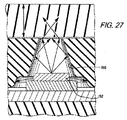
[図27]図24のディスプレイにおける発光部材とキャップ部材の一部を拡大して示す断面図である。
[図28]別形態に係る装置におけるディスプレイの部品の一部を分解して示す斜視図である。
[図29]別形態に係る装置におけるディスプレイの部品の一部を分解して示す斜視図である。
[図30]USBコネクタを内蔵する締結部材の部品を示す部分断面図である。
[図31a]別形態に係る装置における締結機構を示す図である。
[図31b]別形態に係る装置における締結機構を示す図である。
[図32a]別形態に係る装置における締結機構を示す図である。
[図32b]別形態に係る装置における締結機構を示す図である。
[図33a]別形態に係る装置における締結機構を示す図である。
[図33b]別形態に係る装置における締結機構を示す図である。
[図33c]別形態に係る装置における締結機構を示す図である。
[図33d]別形態に係る装置における締結機構を示す図である。
[図34a]別形態に係る装置におけるスペーサアセンブリを示す図である。
[図34b]別形態に係る装置におけるスペーサアセンブリを示す図である。
[図35a]また別の形態に係る装置における締結機構を示す図である。
[図35b]また別の形態に係る装置における締結機構を示す図である。
[図35c]また別の形態に係る装置における締結機構を示す図である。
[図36a]また別の形態に係る装置における締結機構を示す図である。
[図36b]また別の形態に係る装置における締結機構を示す図である。
[図37a]また別の形態に係る装置における締結機構を示す図である。
[図37b]また別の形態に係る装置における締結機構を示す図である。
[図37c]また別の形態に係る装置における締結機構を示す図である。
[図37d]また別の形態に係る装置における締結機構を示す図である。
[図37e]また別の形態に係る装置における締結機構を示す図である。
[図38a]また別の形態に係る装置におけるスペーサアセンブリを示す図である。
[図38b]また別の形態に係る装置におけるスペーサアセンブリを示す図である。
[図39]本発明の装置を形成するプロセスを模式的に示す図である。
[図40]本発明の装置を形成するプロセスを模式的に示す図である。
[図41]本発明の装置を形成するプロセスを模式的に示す図である。
[図42]本発明の装置を形成するプロセスを模式的に示す図である。
FIG. 2 is a perspective view showing the wearable device assembly of FIG.
FIG. 2a shows another embodiment of the wearable device.
FIG. 3 is a front view showing the wearable device of FIG.
4 is a side view showing the wearable device of FIG.
FIG. 5 is a perspective view showing the wearable device of FIG. 2, in which a part of the assembly is made transparent to show internal components.
6 is a cross-sectional view taken along line 6-6 in FIG. 4, schematically showing the wearable device.
[FIG. 7a] It is a perspective view which shows the battery compartment used for the spine member of a wearable apparatus.
FIG. 7b is a perspective view showing the battery compartment as a part of the spine member.
FIG. 8a is a perspective view showing the spine member from the front side.
FIG. 8b is a perspective view showing the spine member from the lower side.
FIG. 9 is a perspective view showing a spine member to which a USB connector is attached.
FIG. 10a shows a USB connector.
FIG. 10b shows a USB connector.
FIG. 10c shows a USB connector.
[Fig. 11a] A diagram showing a receiver member and other components used in the wearable device for fastening a mechanism using a USB connector.
[Fig. 11b] A diagram showing a receiver member and other components used in the wearable device for fastening a mechanism using a USB connector.
[FIG. 11c] A diagram showing a receiver member and other components used in the wearable device for fastening a mechanism using a USB connector.
FIG. 11D is a diagram showing a receiver member and other parts used for the wearable device and fastening a mechanism using a USB connector.
FIG. 11e is a diagram showing a receiver member and other components used in the wearable device for fastening a mechanism using a USB connector.
[Fig. 11f] A diagram showing a receiver member and other components used in the wearable device for fastening a mechanism using a USB connector.
FIG. 12 is a view showing a spacer member and an expansion element used in the wearable device.
FIG. 13 is a perspective view showing a spacer member attached to the wearable device.
FIG. 14 is a plan view schematically showing a flexible circuit member in the controller of the wearable device.
FIG. 15 is a perspective view showing some of the components of the spine member mounted on the apparatus.
FIG. 16 is a perspective view showing some of the components of the spine member mounted on the apparatus.
FIG. 17 is an enlarged view showing an input button associated with a controller.
FIG. 18 is a cross-sectional view showing a part of the input button in FIG.
FIG. 19 is a perspective view showing an exterior member and a battery storage chamber formed on a spine member.
FIG. 19a is a perspective view showing the apparatus from below, showing a battery housing chamber having a port opening.
FIG. 20 is a perspective view showing a part of the battery and the lid member, showing the contacts of the battery.
FIG. 21a is a diagram showing one example of a configuration of a spine member and a battery.
FIG. 21 b is a diagram showing one example of a configuration of a spine member and a battery.
FIG. 21c is a diagram showing one example of a configuration of a spine member and a battery.
FIG. 21d is a diagram showing one example of the configuration of a spine member and a battery.
FIG. 22 is an exploded perspective view of another embodiment of a controller component in the apparatus.
FIG. 23a is a diagram additionally showing a controller part and an index display system in an apparatus according to another embodiment.
FIG. 23 b is a diagram additionally showing a controller part and an index display system in the apparatus according to another embodiment.
FIG. 23c is a diagram additionally showing a controller part and an index display system in an apparatus according to another embodiment.
FIG. 24 is an exploded view showing another embodiment of the index display system associated with the controller component of the apparatus.
[FIG. 25a] It is a perspective view which shows the cap member used for the display of FIG.
FIG. 25b is a bottom view showing a cap member used in the display of FIG. 24.
FIG. 26 is a cross-sectional view showing a part of the display shown in FIG.
27 is an enlarged cross-sectional view showing a part of the light emitting member and the cap member in the display shown in FIG.
FIG. 28 is an exploded perspective view showing part of a display part in an apparatus according to another embodiment.
FIG. 29 is an exploded perspective view showing a part of a display part in an apparatus according to another embodiment.
FIG. 30 is a partial sectional view showing parts of a fastening member incorporating a USB connector.
FIG. 31a is a view showing a fastening mechanism in an apparatus according to another embodiment.
FIG. 31b is a view showing a fastening mechanism in an apparatus according to another embodiment.
FIG. 32a is a view showing a fastening mechanism in an apparatus according to another embodiment.
FIG. 32b is a view showing a fastening mechanism in an apparatus according to another embodiment.
[FIG. 33a] It is a figure which shows the fastening mechanism in the apparatus based on another form.
[FIG. 33b] It is a figure which shows the fastening mechanism in the apparatus based on another form.
[FIG. 33c] A view showing a fastening mechanism in an apparatus according to another embodiment.
[FIG. 33d] It is a figure which shows the fastening mechanism in the apparatus based on another form.
FIG. 34a shows a spacer assembly in an apparatus according to another embodiment.
FIG. 34 b shows a spacer assembly in an apparatus according to another embodiment.
FIG. 35a is a view showing a fastening mechanism in an apparatus according to another embodiment.
FIG. 35b is a view showing a fastening mechanism in an apparatus according to another embodiment.
FIG. 35c is a view showing a fastening mechanism in an apparatus according to another embodiment.
[FIG. 36a] It is a figure which shows the fastening mechanism in the apparatus based on another form.
FIG. 36b is a view showing a fastening mechanism in an apparatus according to another embodiment.
[FIG. 37a] It is a figure which shows the fastening mechanism in the apparatus based on another form.
[FIG. 37b] It is a figure which shows the fastening mechanism in the apparatus based on another form.
FIG. 37c is a view showing a fastening mechanism in an apparatus according to another embodiment.
FIG. 37d is a view showing a fastening mechanism in an apparatus according to another embodiment.
[FIG. 37e] It is a figure which shows the fastening mechanism in the apparatus based on another form.
FIG. 38a shows a spacer assembly in an apparatus according to another embodiment.
FIG. 38b is a view showing a spacer assembly in an apparatus according to another embodiment.
FIG. 39 is a diagram schematically showing a process for forming an apparatus of the present invention.
FIG. 40 is a diagram schematically showing a process for forming the device of the present invention.
FIG. 41 is a diagram schematically showing a process for forming an apparatus of the present invention.
FIG. 42 is a diagram schematically showing a process for forming the device of the present invention.
本発明の様々な実施形態の例に係る以下の記載においては、発明の幾つかの態様が実施される様々な装置、システム、状況が図示を通じて示されるとともに、記載の一部をなす添付の図面が参照される。その他特定の部品、装置、システム、状況の構成が利用可能であるとともに、構造的および機能的な変更が本発明の範囲を逸脱しない限りにおいて可能である。「上」、「下」、「前」、「後」、「横」などの語が、発明の特徴および要素の様々な例を描写するために明細書中で用いられる。これらの語は、例えば図中における方向の例に基づいて便宜的に用いられる。発明の範囲に関して、明細書の記載が構造の3次元的な方向を要求するものと解釈されることはない。 In the following description of various exemplary embodiments of the invention, various devices, systems, and situations in which some aspects of the invention are implemented are shown throughout the drawings and accompanying drawings that form a part of the description. Is referenced. Other specific parts, devices, systems, and configuration of situations are available and structural and functional changes are possible without departing from the scope of the present invention. The terms “upper”, “lower”, “front”, “rear”, “lateral”, etc. are used in the specification to depict various examples of inventive features and elements. These terms are used for convenience based on examples of directions in the figure. With respect to the scope of the invention, the description is not to be construed as requiring a three dimensional orientation of the structure.
(発明の態様についての概説)
本発明は、アスレチック機能を有するウェアラブル電子装置アセンブリを提供する。実施形態の一例においては、ウェアラブル電子装置アセンブリは、装着者にアスレチック情報を伝える発光可能な部分を備えうる。またウェアラブル電子装置アセンブリは、他の装置と(直接的または間接的に)接続可能なデータ送信部を含みうる。一例においては、ウェアラブル電子装置アセンブリは、USBコネクタと記憶装置を含みうる。これらは、データの送受信を行なうために他の装置のUSBポートと接続可能とされる。
(Outline of embodiments of the invention)
The present invention provides a wearable electronic device assembly having athletic capabilities. In one example embodiment, the wearable electronic device assembly may include a light-emitting portion that conveys athletic information to the wearer. The wearable electronic device assembly may also include a data transmitter that can be connected (directly or indirectly) to other devices. In one example, the wearable electronic device assembly may include a USB connector and a storage device. These can be connected to a USB port of another device in order to transmit and receive data.
ある構成においては、ウェアラブル電子装置アセンブリは、USB記憶装置を含みうる。当該装置は、ウェアラブル電子装置アセンブリと他の装置をつなぐコネクタとしても機能しうる。USB記憶装置は、キャリアに接続される。キャリアは、実施形態の一例において、リストバンドである。 In some configurations, the wearable electronic device assembly may include a USB storage device. The device can also function as a connector that connects the wearable electronic device assembly to another device. The USB storage device is connected to the carrier. The carrier is a wristband in an example of the embodiment.
ウェアラブル電子装置アセンブリは、ハウジング部をさらに含みうる。ハウジングはコントローラを支持する。コントローラは、電源や回路といった部品と関連付けられている。3軸加速度計を含む様々なセンサが動作可能にコントローラと関連付けられている。ハウジング部は、耐水性かつ耐衝撃性を有する構造とされている。 The wearable electronic device assembly may further include a housing portion. The housing supports the controller. The controller is associated with components such as a power supply and a circuit. Various sensors, including a three-axis accelerometer, are operatively associated with the controller. The housing part has a structure having water resistance and impact resistance.
ある構成においては、コントローラは、ユーザインターフェースを利用しうる。当該ユーザインターフェースは、装置の機能を高める特徴を有している。例えば、ウェアラブル電子装置アセンブリは、ディスプレイを含みうる。当該ディスプレイは、指標システムを含みうる。当該システムにおいては、パフォーマンスデータがユーザに対して表示あるいは伝達可能とされる。ディスプレイは、LCDスクリーン、LED光源の列からなるディスプレイ、LEDグラフィカルユーザインターフェースなどを含みうる。
ディスプレイに表示されるデータは、内部固定型のメモリ、またはリムーバブルUSB記憶装置に保存されうる。またウェアラブル電子装置アセンブリのUSB装置は、コンピュータに差込み可能であり、パフォーマンスデータが自動的に遠隔サイトやモバイル装置アップロードされうる。アップロードされたデータは、更なる処理、表示や閲覧に供される。
In some configurations, the controller may utilize a user interface. The user interface has a feature that enhances the function of the apparatus. For example, the wearable electronic device assembly can include a display. The display can include an indicator system. In this system, performance data can be displayed or transmitted to the user. The display may include an LCD screen, a display consisting of a row of LED light sources, an LED graphical user interface, and the like.
Data displayed on the display can be stored in an internal fixed memory or a removable USB storage device. Also, the USB device of the wearable electronic device assembly can be plugged into a computer and performance data can be automatically uploaded to a remote site or mobile device. The uploaded data is used for further processing, display and browsing.
またウェアラブル電子装置アセンブリは、ユーザの腰、手首の周り、腕、手、足首、腿などを含む、身体の様々な箇所に装着されうる。 The wearable electronic device assembly can also be worn at various locations on the body, including the user's waist, wrist circumference, arms, hands, ankles, thighs, and the like.
実施形態の一例においては、ディスプレイは指標システムを含みうる。指標システムは、装置アセンブリを装着したユーザの活動のレベルに対応する情報を表示しうる。指標システムは、情報を提供するために選択的に発光可能な発光素子群を含みうる。各発光素子は、複数の色で発光しうる。ディスプレイと指標システムは、ユーザに指標を表示するために、独立して、あるいは協働して動作しうる。 In one example embodiment, the display may include an indicator system. The indicator system may display information corresponding to the level of activity of the user wearing the device assembly. The indicator system may include a group of light emitting elements that can selectively emit light to provide information. Each light emitting element can emit light in a plurality of colors. The display and indicator system may operate independently or in concert to display the indicator to the user.
実施形態の別例においては、ウェアラブル電子装置アセンブリは、スペーサ部材を含みうる。スペーサ部材は、様々なユーザに対応するために、装置のサイズを調節できる。 In another example embodiment, the wearable electronic device assembly may include a spacer member. The spacer member can adjust the size of the device to accommodate different users.
実施形態のさらに別例においては、ウェアラブル電子装置アセンブリは、ユーザに高度な体験を提供するために、モバイル装置や遠隔ウェブサイトとやり取りしうる。 In yet another example embodiment, the wearable electronic device assembly may interact with a mobile device or a remote website to provide an advanced experience to the user.
(発明の具体例)
発明の態様の幾つかについて上記の通り概説したが、本発明に係るアスレチックパフォーマンスをモニタするシステムおよび方法のより詳細な例を、図面を参照しつつ以降の詳細な説明において示す。以降の記載が発明の例についての記載であり、当該記載によって発明を限定的に解釈すべきでないことは、当業者にとって明らかである。
(Specific examples of the invention)
While some of the aspects of the invention have been outlined above, more detailed examples of systems and methods for monitoring athletic performance according to the present invention are presented in the detailed description that follows with reference to the drawings. It will be apparent to those skilled in the art that the following description is a description of examples of the invention and the description should not be construed as limiting the invention.
図1は、本発明に係る実施形態の一例としてのアスレチックパフォーマンスの監視およびフィードバックシステム1を利用している人を示す。当該システム1は、アスレチック機能を有するウェアラブル装置アセンブリ10を含む。後に詳述するように、ウェアラブル装置アセンブリ10は、3軸加速度計のようなセンサを有し、アスレチック活動やユーザの活動全体をモニタ可能である。
図1に示すように、アスレチックパフォーマンスの監視およびフィードバックシステム1は、センサ2とモバイル装置3も含む。センサ2は、可搬型のものであるか、靴に埋設されている。システム1は、必要に応じて心拍計など他のセンサや装置を含みうる。
後に詳述するように、ウェアラブル装置アセンブリ10は、無線通信を通じてアスレチックパフォーマンスやユーザの活動全体を記録および監視する。当該目的のために装置アセンブリ10を単体で使用してもよい。アスレチックパフォーマンスや活動は、様々なパラメータ、指標、生理学的特性を含む。例えば速度、距離、歩数、カロリーのようなエネルギー消費量、心拍数、発汗などが含まれるが、これらに限定されるものではない。このようなパラメータは、ユーザの活動に基づいて獲得されるポイントや通貨として表されうる。
FIG. 1 shows a person using an athletic performance monitoring and
As shown in FIG. 1, the athletic performance monitoring and
As will be described in detail later,
センサ2は、様々な電子部品を有しうる。当該電子部品には、電源、磁気センサ素子、マイクロプロセッサ、メモリ、送信システムなどが含まれる。本実施形態の例においてセンサ2は、図1に示すようにユーザの靴に搭載される。センサ2は、システムの他の要素と併せて使用され、速度や距離などのアスレチックパフォーマンスに係るパラメータのデータを記録する。
センサ2は、米国特許出願公開2007/0006489号、2007/011919号、および2007/0021269号公報に開示のものでありうる。これらの米国公報は参照として取り込まれ、本明細書の開示の一部とされる。センサ2は、ユーザに関連付けられたデータを収集する力センサアレイの形態もとりうる。当該形態は、例えば米国特許出願公開2010/0063778号、および2010/0063779号公報に開示されており、これらは参照として取り込まれ、本明細書の開示の一部とされる。
モバイル端末3は、スマートフォンや、その他の携帯表示装置でありうる。ウェアラブル装置アセンブリ10は、その他のセンサとやり取りや通信が可能である。例えば、衣料内蔵型センサや、競走会やその他のアスレチック競技会のようなイベントに関連付けられたセンサが含まれる。
The
The
The
図2から図6は、図1のウェアラブル装置アセンブリ10を異なる視点で示す。ウェアラブル装置アセンブリ10は、ハウジング12、コントローラ14、入力ボタン16、ディスプレイ18、および指標システム20を少なくとも含む。コントローラ14は、電源、センサ群、回路を含む様々な関連する部品群を備えているか、操作可能に接続されている。図2aは、より大きな標識システム20を有する装置アセンブリ10の別例を示す。まず装置アセンブリ10の構造について以下記載し、次いでその動作について記載する。さらに装置アセンブリ10と関連するシステムにより提供される追加のユーザエクスペリエンスについて記載する。
2-6 illustrate the
ハウジング12は、リストバンドのようなウェアラブルバンドの形態を呈しており、電源用のコンパートメントを有するインナースパイン部材22(図6から図9参照)、外装部材24、および締結部材26を少なくとも含む。実施形態の一例において、ハウジング12は、装置アセンブリ10のサイズを調節する少なくとも1つのスペーサ部材28を有しうる(詳細は後述)。
The
図2から図6にさらに示すように、ウェアラブル装置アセンブリ10は、環状あるいは略円形状を呈している。図示の例においては、ユーザの手首周りに装着する構成とされている。ウェアラブル装置アセンブリ10は、発明から逸脱しない限りにおいて、その他の様々な形状とされうる。例えば、楕円状、長円状、八角形状、矩形状などである。装置アセンブリ10は、クリップなどの装置に装着される構成にもされうる。当該装置は、人体に着脱可能とされるか、衣料などの一部とされうる。
ハウジング12は、略平坦な部分、および両側部に沿う湾曲あるいは面取りされた縁を有しうる。実施形態の一例において、面取りされた縁は、ハウジング12の一方の側部のみに含まれうる。ハウジング12の両端は、締結部材26により結合される構成とされている。
ハウジング12の外側面は滑らかな質感とされ、内側面(装着者の身体に接触する面)はザラザラとした質感とされうる。一例として、ウェアラブル装置アセンブリ10の内側面には、摩擦性を増してユーザの手首などの周りで滑ることを防止するためのリブが形成されうる。質感は、内側面全体で均一とされても非均一とされてもよい。例えば、ハウジング12の両端に形成された締結部材26から離れた部分のみリブなどが形成されうる。別例として、外側面にそのような質感が施され、内側面が滑らかとされてもよい。様々な質感の組合せと構成が採用されうる。さらに別例として、ハウジング12は、吸汗部材あるいは乾燥材を内側面に備えうる。
As further shown in FIGS. 2-6, the
The
The outer surface of the
図7から図9に示すように、スパイン部材22は、ほぼ非可撓性の部分と、ある程度柔軟な部分あるいは領域とを有する部材である。後述するように、スパイン部材22は、少なくともコントローラ14の部品を支持する。スパイン部材22は、様々な部品が装着されたシャーシ部材ともみなしうる。
スパイン部材22は、外側面30と内側面32を有する湾曲形状を呈している。スパイン部材22は、第1端部36から第2端部38へ延びる中間部34を有する。中間部34は、中央部40、第1セグメント42、および第2セグメント44を有する。中間部34は、第1可撓部46と第2可撓部48をさらに有する。第1可撓部46は、中央部40の一端と第1セグメント42を接続する。第2可撓部48は、中央部40の他端と第2セグメント44を接続する。これらの可撓部46、48は、当該部位においてスパイン部材22(装置アセンブリ全体)を曲がりやすくする。一方、第1セグメント42、第2セグメント44、および中央部40は、曲がらない、あるいは曲がりにくい部分とされる。
実施形態の一例において、フレキシブルなヒンジ領域とみなされうる可撓部46、48は、窪み形状を有する湾曲したセグメントである。よってフレキシブル領域は、中央部あるいは基部と、当該部分より延びる、一対の部分とを有する。当該一対の部分は、内側に湾曲した部分を区画する。湾曲セグメントは、窪み形状中央の基部において肉薄とされ、可撓部46、48の柔軟性を高めている。
よってスパイン部材22は、その長さ方向に沿って基本厚みあるいは第1厚みを有する(例えば、非可撓性の中央部40と第1、第2セグメント42、44)。一方、可撓部46、48は、より小さな第2厚みtを有し、スパイン部材22およびハウジング12全体の柔軟性を高めている。特に、可撓部46、48の基部は、非可撓性の中央部40と第1、第2セグメント42、44よりも小さな厚み寸法を有する。後に詳述するように、可撓部46、48は、スパイン部材22に支持された部品群が中立軸に最も近づかせる。当該中立軸においては、装置アセンブリ10がユーザの腕に対して着脱される際のストレスが最小化される。
図7から図9に示すように、中間部34の第1セグメント42は、第1収容凹部50を有し、第2セグメント44は、第2収容凹部52を有する。これらは湾曲形状を呈している。収容凹部50、52は、コントローラ14用の電源を受け入れる寸法とされている。
図7aと図7bに示す実施形態の一例において、収容凹部50、52は、まずチキソ成形された金属部材55のような金属製の筐体から形成される。収容凹部50、52は、鋳造された金属部材、ダイキャスト部材、射出成型された金属部材から形成されてもよい。
キャップの形態を呈する金属製のカバーあるいは蓋部材も、電源用の金属筐体を構成する。バッテリ142用の金属筐体を形成するにあたり、対向する金属部材群を用いることが好ましく、バッテリが包囲されていれば、完全な部屋状の空間を形成する必要はない。
まず収容凹部50、52がチキソ成形され、次いでスパイン部材22の残りの部分が当該収容凹部を覆うようにチキソ成形されうる。スパイン部材22の一部は、収容凹部50、52の底部をなすチキソ成形された部材を覆うように形成されうる。
後述するように、収容凹部50、52は、バッテリ端子や接点を受容する一対の開口59をさらに有する。収容凹部50、52の寸法は、図示したものと異なっていてもよく、また相互に異なっていてもよい。よって収容凹部50、52は、より大きな容量と寸法を有する電源を収容すべく、より大きな寸法を有しうる。この点については後に詳述する。
As shown in FIGS. 7 to 9, the
The
In an example embodiment, the
Accordingly, the
As shown in FIGS. 7 to 9, the
In the example of the embodiment shown in FIGS. 7 a and 7 b, the
A metal cover or lid member in the form of a cap also constitutes a metal casing for power supply. In forming the metal casing for the
First, the accommodation recesses 50 and 52 can be thixo-molded, and then the remaining portion of the
As will be described later, the
後述するように、中間部34は、外側面30の近傍に、ディスプレイ18や標識システム20とともにコントローラ14の他の部品をさらに支持する。スパイン部材22は、標識システムを支持する面取りされた縁を有しうる。スパイン部材22は、締結機構26を受容する幾つかの開口を有する。コントローラの部品群をスパイン部材22に対して装着固定する締結機構26としては、接着剤やねじ留め具が挙げられる。第1端部36と第2端部38は、締結機構26とスペーサ部材28を支持する。
As will be described later, the
実施形態の一例において、収容凹部50、52の形成を助けるチキソ成形された部材55は、マグネシウムからなる。当該部材55を覆うスパイン部材22の残りの部分は、ポリポロピレン材料からなる。スパイン部材22には他の材料も用いうる。バッテリ収容部についても同様である。
図2、図3、図6、および図19に示すように、外装部材24は、スパイン部材22の周囲に配置され、コントローラ14、ディスプレイ18、および標識システム20を包み込む。実施形態の一例において、外装部材24は、射出成型プロセスにより形成される熱可塑性エラストマ部材である。詳しくは後述する。そのため外装部材24は、環状形態を保つように回復性のある弾性を有する。
外装部材24は、全体的に湾曲した外表面56と全体的に平坦な内表面58を有している。外装部材24の内側部分と外側部分は、それぞれ装置アセンブリ10の内径と外径を規定しているともみなせる。外表面56は、カーブを形成しつつも平坦に見える程度に大き目の曲率半径を有する。側縁は、外表面56よりも小さい曲率半径を有し、面取りされた縁は、さらに小さな曲率半径を有する。外装部材24の表面同士は、装置の様々な部品を収容する内側空間をさらに形成する一方、最小の断面積を維持している。
外装部材24は、面取りされた側縁60をさらに有する。標識システム20は、当該面取りされた側縁60の近傍に配置される。ハウジング12は、必要に応じて、各側縁が面取りされたものとされうる。
外装部材24は、コントローラ14とやり取りするための入力ボタンを収容する開口62を有する。外装部材24は、ディスプレイ18の表示部分を収容する第1領域64と、標識システム20の表示部分を収容する第2領域66とを有する。外装部材24の第1領域64は、当該領域を通じてディスプレイ18により投影された標識群が視認可能とされるような構造と寸法とを有する。外装部材24の第2領域66は、当該領域を通じて標識システム20により投影された標識群が視認可能とされるような構造と寸法とを有する。
外装部材24は、暗い見た目を提供する着色剤を含んでいる。着色剤の量は、外装部材24により包装される部品群が見えなくなる程度に調整される。しかしながら、ディスプレイ18と標識システム20が起動されると、光は外装部材24を容易に通過して、視認可能とされる。例えば、実施形態の一例において、外装部材24は、ある程度の比率で着色剤を含んだ半透明の熱可塑性エラストマとされる。
外装部材24は、全体として透明ではあるが、ある程度の量の黒顔料を含む材料からなる構成としてもよい。この場合、外装部材24の内部の部品群は視認できないが、ディスプレイ18と標識システム20が起動されると、発光する部材群が外装部材24を通じてはっきりと視認される。すなわち、内部の部品群は肉眼では視認されないが、ディスプレイ18や標識システム20は、その起動時に外装部材24を通じて視認可能とされる。
また装置アセンブリ10は、ディスプレイ18と標識システム20の一方が常時視認可能であり、他方が起動時にのみ視認可能となるように構成されうる。例えば、ディスプレイ18は日時を示すために常時視認可能とされる一方、標識システム20は起動時にのみ視認可能とされうる。
外装部材24は、様々な着色剤を含む無色の材料とされうる。特定の色は、装置アセンブリ10を特定の用途やイベントのためにデザインされたものであると示しうる。第1領域64と第2領域66は、透明とされうる。実施形態の一例においては、暗めの色で着色されたこれらの領域を通じて、ディスプレイ18と標識システム20が発光する。あるいは、ディスプレイ18と標識システム20を視認するための開口群が第1領域64と第2領域66に形成されうる。
外装部材24の内表面58は、スパイン部材22に支持された電源の位置の近くに第1開口68と第2開口70を有する。第1開口68は、第1キャップ72に覆われるか、蓋部材が留め具により固定される。第2開口70は、第2キャップ74に覆われるか、蓋部材が留め具により固定される。第1キャップ72と第2キャップ74は、金属材料で形成され、金属製の収容凹部50、52と協働して、後述する電源用の金属筐体をなす。
外装部材24は、様々な材料で形成されうる。材料としては、様々なポリマー、プラスチック、ゴム、熱可塑性エラストマ、熱可塑性ウレタン、液体シリコン、合成ゴム材、成形可能な弾性材料、合成物などが挙げられる。合成物は、ネオプレン(登録商標)、プラスチック、繊維、金属同士の合成物、あるいはこれらの組合せによる合成物でありうる。例えば、材料には熱可塑性ポリウレタンや熱可塑性ゴムが含まれうる。
ウェアラブル装置アセンブリ10により形成されるループ形状が、破損することなく拡開するように、使用される材料は、柔軟性をもたらすものでもあるとよい。
後に詳述するように、スパイン部材22とこれに支持される部品群には、外装部材24と接着されやすくするために、接着促進剤が用いられうる。
スパイン部材22と外装部材24については、後に装置アセンブリ10を形成するプロセスについて述べる際に、より詳しく説明する。
In an example embodiment, the
As shown in FIGS. 2, 3, 6, and 19, the
The
The
The
The
The
The
The
The
The
The material used may also provide flexibility so that the loop shape formed by the
As will be described in detail later, an adhesion promoter may be used for the
The
図6、図10、および図11に示すように、締結部材あるいは留め具26は、少なくとも第1突出部材90と第2受け部材92を含む。第1突出部材90は、ハウジング12の第1端部の近傍に配置される。第2受け部材92は、ハウジング12の第2端部の近傍に配置される。当該部材90、92は、必要に応じてハウジング12の両端部に配置されうる。
第1突出部材90は、データ転送のための入出力部材94を内蔵している。実施形態の一例において、当該部材はほぼ非可撓性の本体96を有するUSBコネクタ94の形態をとる。USBコネクタ94は、本体96の上面に埋設された複数のリード群98を含む。リード群98は、操作可能にコントローラ14と接続されるコネクタを有する。図10cに示すように、第1突出部材90は、リード群98の反対側にある本体96の底面に位置する凹部100をさらに有する。凹部100は、係合面102を区画する。
As shown in FIGS. 6, 10, and 11, the fastening member or
The first projecting
図6、図11a〜図11fに示すように、第2受け部材92は、開口104を区画し、回動部材106を支持する。支持部材106は、指部108を有し、当該指部108を係止位置へ付勢するバネ110を含む。第2受け部材92は、開口104と逆側の端部に一対の突起部材120をさらに有する。突起部材120は、傾斜あるいは湾曲したカム面122を有する。スロット124が突起部材120の長さ方向に沿って形成されている。
As shown in FIGS. 6 and 11 a to 11 f, the second receiving
図11a〜図11fに示すように、第1突出部材90は、本実施形態においてはスパイン部材22の一端に接続されうる第2受け部材92内に受容される。まず指部108が回動して係止位置から離れる方向に付勢される。指部108が凹部100を一旦通過すると、指部108はバネ110によって凹部100内の係止位置へ付勢される。すると装置アセンブリ10は、指部108が係合面102の当接可能となる閉じ位置に至る。当該位置において装置アセンブリ10は、閉じた環状の形態となる。
実施形態の一例において、締結部材26は、USBコネクタ94を内蔵している。しかしながら、他の通信用接続構成も採用されうる。例えば、マイクロUSBコネクタ、ファイヤーワイヤー(登録商標)ポート、16ピンポートなどの物理的接触を伴う接続、あるいは、ワイファイ(登録商標)、ブルートゥース(登録商標)、近距離通信、RFID、ブルートゥースローエナジー(登録商標)、ジグビー(登録商標)などの無線通信技術用の無線あるいは非接触通信インターフェース、赤外線通信技術や光通信技術用のインターフェースが利用されうる。
装置アセンブリ10は、通信やデータ転送を、USBコネクタ94のようなデータ転送部材のみを用いて行なうように構成されてもよく、無線通信のみを用いて行なうように構成されてもよく、無線通信と様々なタイプのプラグイン通信の双方を組み合わせて行なうように構成されてもよい。
As shown in FIGS. 11 a to 11 f, the first protruding
In one example of the embodiment, the
The
図10a〜図10cは、USBコネクタ94を示す別図面である。USBコネクタ94は、操作性を保ちつつも、より美しく、アスリートにとってより魅力的な構造的特徴を有している。従来のUSBコネクタにおいては、リード群は不揃いの間隔で並び、矩形状であり、かつ各端部の位置が揃っていない。図10aに示すように、USBコネクタ94のリード群98は、本体96を横切るように等間隔で並んでいる。またリード群98は、本体96の上面114に対して窪んでいる。さらに、角のとれた形状の開口群116が本体96に形成されて等間隔に並んでいるとともに、開口群116の両端位置は揃っている。
リード群98は、開口群116により露出している。リード群98は本体96の上面114に対して窪んでいるため、各リード98は、本体96の上面114の近傍まで盛り上がったリブ118を有している。
実施形態の一例において、リード群98は、金型内に配置される。材料が金型内のリード群98の周囲に射出成型され、形と位置が揃い、角のとれた形状の開口群116を有する本体96を形成する。このような構成により、改良されたUSBコネクタ94が得られる。
10a to 10c are other drawings showing the
The
In an example embodiment, the
装置アセンブリ10は、その周長が可変とされている。すなわち、装置アセンブリ10は、例えばサイズの異なるユーザの手首に巻けるように、大小様々なループを形成できる。そのためハウジング12は、図12および図13に示すように、スペーサ部材28あるいは拡張部材28を内蔵しうる。スペーサ部材28は、単数でも複数でもよい。あるいは全く使用せずに、ハウジング12の両端に接続された締結機構を有するのみでもよい。
スペーサ部材28は、ハウジング12の一端および締結機構26の受け部材92の一端と結合して装置アセンブリ10の周長を増大させる。スペーサ部材28は、本体130を有している。本体130は、その一端に一対の開口132を有している。一対の開口132は、締結部材26の受け部材92に配置された一対の突起部材120を受容する寸法とされている。本体130は、開口対132の近傍にて回転爪134を支持する。回転爪134は、湾曲したカム面135と付勢バネ136を有する。回転爪134は、図12bに示す締結具とカバー板により、本体130の略中央部に固定される。回転爪134は、当該略中央部を中心に回転可能である。
本体130の他端は、一対の突起部材137を支持する。受け部材92の突起部材120と同様に、突起部材137はカム面138を有する。図11fと図13より明らかなように、スペーサ部材28を用いる場合、突起部材137は、ハウジング12の端部に形成された開口に受容および固定される。ハウジング12の当該端部は、突起部材137に対応する構造を有する。
締結機構26における受け部材92が備える一対の突起部材120は、スペーサ部材28の本体130が備える一対の開口132に挿入される。これにより、受け部材92の傾斜したカム面122が回転爪134のカム面135に係合し、回転爪134が回転する。回転の様子は、図12cにおいて矢印Aで示す。なお同図においては、明確化のためにカバー板を省略している。これにより突起部材120の開口132へのさらなる挿入が許容される。
突起部材120のスロット124が回転爪134に並ぶと、回転爪134の両端はスロット124に受容され、スペーサ部材28を締結機構26の受け部材92に固定する(図11fと図13を参照)。装置アセンブリ10からスペーサ部材28を取り外したい場合に、回転爪134を回転させるためのアクセス孔が設けられうる。
サイズを大きくするためには、複数のスペーサ部材28が使用されうる。サイズを小さくするためには、スペーサ部材28を取り外せばよい。スペーサ部材28の長さは、例えば5〜10mmの範囲で変更可能である。一例として、各スペーサ部材28の長さは8mmとされうる。別例として、各スペーサ部材28の長さは6mmとされうる。スペーサ部材28を使用しない場合、受け部材92上の突起部材120は、ハウジング12の一端に結合し、固定される。
実施形態の一例において、スペーサ部材28は、ハウジング12と同様の構造を有しうる。例えば、本体を覆う熱可塑性部材を有するプラスチックのボディとされる。突起部材120は、本体に挿入された金属の一部とされうる。実施形態の一例において、スペーサ部材28を用いる装置アセンブリ10の内径は、約147〜221mmの範囲で可変とされる。
The peripheral length of the
The
The other end of the
The pair of projecting
When the
In order to increase the size, a plurality of
In an example embodiment, the
装置アセンブリ10は、ハウジング12により支持されたコントローラ14を有する。コントローラ14は、様々な部品を有するプリント回路基板140を少なくとも含む。様々な部品には、回路、処理ユニット群、データ保存メモリ、コネクタ群、本技術分野において考えられるその他の部品群(図43参照)が含まれる。
コントローラ14は、バッテリパックやバッテリの形態である電源142、アンテナアセンブリ144、センサアセンブリ146をさらに含む。コントローラ14は、音声情報を伝えるためのスピーカといった他の部品群も有しうる。図43は、コントローラ14のブロック図であり、後に詳述する別の部品群を示している。
The
The
図14は、プリント回路基板(PCB部材)140を模式的に示す。実施形態の一例において、PCB部材140はフレキシブル回路部材である。PCB部材140は、様々な部品を支持する複数の領域あるいは区域を有する。PCB部材140は、ディスプレイ18と標識システム20が動作可能に接続された中央領域140aをさらに有する。PCB部材140は、スパイン部材22の可撓部46、48に対応する位置に、可撓領域140bをさらに有する。他の部品群もPCB部材140に接続されうる。
図15と図16に示すように、PCB部材140は、スパイン部材22を包むように装着される。PCB部材140をスパイン部材22に固定するに際しては、締結具も用いられうる。接続により、PCB部材140の中央領域140aは、スパイン部材22の中間部34に対応する。PCB部材140は、可撓部46、48の外郭を含むスパイン部材22の外郭に概ね沿うように延びる。よって可撓領域140bは、スパイン部材22の可撓部46、48の位置に配置され、面係合する。この構成により、PCB部材140の中立軸近傍への変位が許容され、装置アセンブリ10が曲げられたときにPCB部材140に作用するストレスが最小化される。
FIG. 14 schematically shows a printed circuit board (PCB member) 140. In one example embodiment, the
As shown in FIGS. 15 and 16, the
上述のように、PCB部材140は、コントローラ14の様々な部品を支持する。例えばPCB部材140は、アンテナアセンブリ144とセンサアセンブリ146を支持する。PCB部材140は、データ保存メモリに係る部品群をさらに支持する。データ保存メモリは、センサアセンブリ146からの入力を受信する。USBコネクタ94からの入力も同様に受信する。コントローラ14により保存されたデータは、USBコネクタ94を経由して、コンピュータなどの他の装置に転送もされうる。当該データは、当該コンピュータを経由して遠隔地にも転送されうる(図44参照)。
As described above, the
PCB部材140により支持されたアンテナアセンブリ144は、他のモバイル装置との通信を支援する。よって装置アセンブリ10は、モバイル装置群と無線通信が可能である。実施形態の一例において、コントローラ14は、ブルートゥース通信を利用する。したがってコントローラ14は、ブルートゥース無線器を有し、装置アセンブリ10がモバイル装置と無線通信できるようにアンテナアセンブリ144を利用する。装置アセンブリ10は、そのような無線通信に必要な他の部品群も装備している。そのような通信については、後に詳述する。
上述のように、PCB部材140は、センサアセンブリ146を支持する。センサアセンブリ146は、複数の異なるセンサを備えうる。実施形態の一例において、センサアセンブリ146は、3軸加速度計を備える。後に詳述するように、センサアセンブリ146は、装置アセンブリ10を装着したユーザの活動に対応する動きを検出する。
システム1とコントローラ14の少なくとも一方は、必要に応じて他のセンサも含みうる。例えば、ユーザに利用されるシステム1は、装置アセンブリ10と通信する靴内蔵型のセンサを利用しうる。ユーザは、装置アセンブリ10と通信可能な衣料内蔵型センサも所有しうる。
センサアセンブリ146は、心拍数センサを含みうる。心拍数センサは、必要に応じて胸装着型のセンサとされうる。心拍数センサは、装置アセンブリ10のハウジング12に内蔵された、ユーザの手首の近くで心拍数を検出するセンサであってもよい。
GPSセンサなどの他のセンサも利用可能である。他のセンサも装置アセンブリ10に内蔵されうる。実施形態の一例において、センサは、ジャイロスコープセンサを含みうる。当該センサは、微小電子機械システム(MEMS)型のジャイロスコープセンサとされうる。
加速度計のように装置内の他のセンサと協働するセンサは、進歩した機能や対応性を提供し、また検出されるユーザの動きに対する差別化をもたらす。
As described above, the
At least one of the
Other sensors such as GPS sensors can also be used. Other sensors can also be incorporated into the
Sensors that cooperate with other sensors in the device, such as accelerometers, provide advanced functionality and responsiveness, and also provide differentiation to detected user movement.
上述のように、コントローラ14は、バッテリの形態である電源142を含む。仕様に応じてバッテリは単数でも複数でもよい。単一のバッテリを用いる場合、装置アセンブリ10に係る他の部品群を支持する他の領域を有するフレキシブル回路部材が用いられうる。しかしながら本実施形態において、電源142は一対のバッテリを用いる。
図6と図20から明らかなように、一対のバッテリ142は、湾曲した形状を呈する、ほぼ非可撓性の部材である。バッテリ142の表面は、湾曲した平面をなしている。第1のバッテリ142は、スパイン部材22の第1収容凹部50内に配置され、第2のバッテリ142は、スパイン部材22の第2収容凹部52内に配置される。一対のバッテリ142は、収容凹部50、52の深さにほぼ対応する厚みを有する。一対のバッテリ142は、スパイン部材22の内側面32とほぼ同一面をなしている。一対のバッテリ142は、コントローラ14と動作可能に接続され、装置アセンブリ10に電力を供給する。
図20に示すように、バッテリ142は、弾性を有する立ち上がり部148を有する。立ち上がり部148は、一対の丸みを帯びた突起149、および一対の接点150を有する。各接点150は、各突起に貼り付けられている。
一対のバッテリ142が収容凹部50、52内に配置されると、接点150は、収容凹部50、52の開口59を通過して延び、PCB部材140と係合して装置アセンブリ10に電力を供給する。
キャップ70、74がスパイン部材22に対して締め付けられると、突起149と接点150は、PCB部材140に対して弾性的に押し付けられ、より安定した導電接触をもたらす。各バッテリ142がこのような立ち上がり部材148を利用する。実施形態の別例においては、導電性エポキシ部材が接点150の接着に用いられうる。
バッテリ容量と充電が必要となるまでの装置寿命を増大させるために、バッテリ142の全体寸法と収容凹部50、52は大きくされうる。非可撓性のバッテリ142は、スパイン部材22におけるより堅牢な第1セグメント42と第2セグメント44に装着されることが好ましい。スパイン部材22の可撓領域46、48は、セグメント42、44とバッテリ142を蝶番状に回動可能とする。これにより、装置アセンブリ10のハウジング12に柔軟性がもたらされる。
As described above, the
As apparent from FIGS. 6 and 20, the pair of
As shown in FIG. 20, the
When the pair of
As the
In order to increase the battery capacity and device life until charging is required, the overall dimensions of the
図2〜図6、および図16〜図19に示すように、装置アセンブリ10は、装置の操作を支援する押下可能な入力ボタン16を含む。図17と図18から明らかなように、入力ボタン16は、コントローラ14と動作可能に接続され、ディスプレイ18に概ね隣接するようにハウジング12に支持される。入力ボタン16は、ハウジング12の外装部材24を通じて延びており、ユーザが触れられるようになっている。
入力ボタン16は、二色成形プロセスにより一体成型された非可撓性のベース部材76と可撓性のキャップ78を有している。コントローラ14とやり取りが可能なタクトスイッチを支持する内部空間79が、入力ボタン16により区画される。ベース部材76は、第1ツール面82を形成する上リング80と、キャップ78に隣接して第2ツール面86を形成する下リング84を有する。装置アセンブリ10を形成するプロセスの間、スパイン部材22、およびこれに支持される部品群の周りに外装部材24が射出成型されるとき、第1ツール面82と第2ツール面86は、きつく面係合してツールを形成する。この係合は、型内に射出された材料が入力ボタン16の内部空間79内に流れ込むのを防ぐ。これにより入力ボタン16の誤動作が防止される。入力ボタン16経由で行なわれる入力操作によりもたらされる装置アセンブリ10の動作については、後に詳述する。
As shown in FIGS. 2-6 and 16-19, the
The
図2、図15、および図16に示すように、装置アセンブリ10のディスプレイあるいはディスプレイシステム18は、ハウジング12に支持され、コントローラ14と動作可能に接続される。ディスプレイ18は、装置アセンブリ10またはハウジング12の発光可能部とみなされうる。
ディスプレイシステム18は、独立した複数の発光素子または発光部材(実施形態の一例においてはLED素子群152)を含みうる。LED素子群152は、アレイを形成し、PCB部材140の中央部と動作可能に接続されうる。LED素子群152は、各LED素子を様々な組合せで発光させることで単語、文字、数字、記号などが形成されるように、配列されうる。例えば、LED素子群152は、所定の行数と列数を有するマトリクスを形成するように配列されうる。
ハウジング12の外装部材24は、LED素子群152を包囲および保護する。上述のように、外装部材24は、第1領域64(図19参照)を有する。第1領域64は、LED素子群152の位置に対応しており、LED素子が発光すると、外装部材24を通じてその光が見える。実施形態の別例として、第1領域64は、透明あるいはほぼ透明とされうる。すなわち、第1領域64は、独立的かつ個別的でありうる。例えば、発光領域の各々は、外装部材24の不透明または半透明の部分により包囲され、各LED素子152からの発光が混じり合わないようにされる。
As shown in FIGS. 2, 15, and 16, the display or
The
The
ディスプレイシステム18は、装置アセンブリ10の全周長における一部にのみ形成されうる。例えば図2に示すように、装置アセンブリ10の頂部あるいは中央部を占有する。頂部あるいは中央部とは、締結機構26の反対側である。
ディスプレイシステム18の大きさ、すなわちLED素子群152の数、マトリクスの行数および列数、全体の幅や長さは、一度に表示されるデータの最大量、使用されるフォントや文字の大きさ、あるいはそれらの組合せに基づいて定められる。一例として、ディスプレイシステム18は、5列、計20個のLED素子群152から構成されうる。ここで各列は装置アセンブリ10の長手方向とほぼ平行に延びる。
なお外周の全長(例えば、装置アセンブリ10の外側を向く面における長さ)は、174〜182mmの範囲とされうる。
ディスプレイ18は、装置アセンブリ10がブルートゥース通信のような無線通信をモバイル装置と実行中であることを示す発光部材を含みうる。
The
The size of the
Note that the entire length of the outer periphery (for example, the length on the surface facing the outside of the device assembly 10) may be in the range of 174 to 182 mm.
図2、図15、および図16に示すように、装置アセンブリ10の標識システム20は、ハウジング12に支持され、コントローラ14と動作可能に接続される。標識システム20は、ディスプレイ18全体の一部あるいは部品とみなされうる。標識システム20は、第1ディスプレイと第2ディスプレイを含みうる。標識システム20は、ディスプレイ18と協働して、あるいはディスプレイ18とは完全に独立して動作し、発光しうる。
標識システム20は、別の複数の発光素子群あるいは発光部材群160(実施形態の一例においては、LED素子群)を含みうる。発光素子群160は、コントローラ14と動作可能に接続され、PCB部材140に支持される。標識システム20は、ハウジング12の側縁付近に配置される。一例として、標識システム20は、計20個の発光素子群160を含みうる。別例として、発光素子群160は、装置アセンブリ10のハウジング12における両側縁に沿って配列されうる。
実施形態の一例において、発光素子群160は、直線的に配列される。標識システム20における発光素子群160は、ディスプレイシステム18における発光素子群152とは異なった配列とされうる。形状、大きさ、外観などの相違は、ユーザに伝えられる情報の種類を特定できるようにしうる。例えば発光素子群160は、ハウジング12の面取りされた側縁60の少なくとも1つに沿って配列されうることにより、ユーザによる視認を容易にする。装置アセンブリ10の側部や縁部が丸められている例においては、丸められた縁部の湾曲した輪郭に沿って発光素子群160が配列されうる。これにより、装着時において発光素子群160からの光が見える。例えば、装置アセンブリ10が装着されるユーザの手首や身体の一部から離れる方向において光が見える。
ディスプレイ18の発光素子群152に係る構成と同様に、外装部材24は、第2領域66(図19参照)を有する。第2領域66は、発光素子群160の位置に対応している。標識システム20の発光素子群160から出射された光は、第2領域66において、外装部材24を通じて見える。実施形態の別例として、第2領域66は、透明あるいはほぼ透明とされうる。
例えば、発光素子群160により形成される照明の外観は、外装部材24における対応部分の大きさ、形状、透明度などの外観的属性により定められうる。例えば、発光素子群160が実際には円形状(円形の電球)であったとしても、外装部材24の発光部として透明な矩形領域を用いれば、矩形の表示器を構成できる(図2a参照)。
表示システム20の発光素子群160は、装置アセンブリ10の外周部分に沿って配置されうる。一例として、ディスプレイ18の長さとほぼ同じ長さだけ配置されうる。標識システム20とディスプレイ18の発光素子群同士の間隔は、同様とされうる。発光部材160の配列長さは、全周長の半分でもよいし、3分の1でもよいし、4分の3でもよい。発光素子群160は、装置アセンブリ10のほぼ全周長にわたって配列されてもよい。
発光素子群160は、複数のセグメントを形成すべくグループ化されたものを含みうる。異なるセグメントは、異なる発光の仕方をされうるが、詳細は後述する。発光素子群160の各々は、ディスプレイにおける独立かつ別個のセグメントとみなしうる。
ディスプレイ18と標識システム20に係る上記の構成によれば、ディスプレイ18は光を第1方向に出射可能であり、標識システム20は光を第2方向に出射可能である。ここで第1方向と第2方向は異なる。実施形態の一例において、第2方向は、第1方向と交差する向きでありうる。上述の発光素子群は、提供する発光特性に応じた適宜の形状と構造を有しうる。
As shown in FIGS. 2, 15, and 16, the marking
The
In one example of the embodiment, the light emitting
Similar to the configuration related to the light emitting
For example, the appearance of illumination formed by the light emitting
The light emitting
The light emitting
According to the above configuration relating to the
図39〜図42は、本発明に係るウェアラブル装置アセンブリを造る成形プロセスを模式的に示す。図39において、第1成形型170は、ウェアラブル装置アセンブリ10のスパイン部材22を造るために用いられうる。上述のように、スパイン部材22の構造的特徴は、ウェアラブル装置アセンブリ10における様々な電子部品と非電子部品の装着、挿入、および結合を許容する。スパイン部材22は、第1成形型170内に射出される熱可塑性材料のようなプラスチック材料から成形されうる。スパイン部材22は、可撓部に対応する数箇所において肉薄とされうる。これにより当該箇所に可撓性が与えられる。一方、バッテリを支持するセグメントなどに対応する他の部分は、肉厚とされうる。これにより当該箇所に剛性が与えられる。また回路や発光素子(LEDなど)のような電子部品群は、破損を避けるためにより剛性の高い個所に装着されうる。
続いてスパイン部材22に対して、上述した他の部品群が組み付けられる。例えば、バッテリパック142、回路群、ディスプレイ18、および標識システム20が、スパイン部材22に組み付けられうる。
39-42 schematically illustrate a molding process for making a wearable device assembly according to the present invention. In FIG. 39, the first mold 170 can be used to make the
Subsequently, the other component group described above is assembled to the
図40に示すように、様々な部品群の幾つかを支持したスパイン部材22の組立体は、射出コア172に装填され、さらなる射出成型に供されうる。ここではスパイン部材22の内径あるいは内側部分が射出成型されうる。図41と図42に示すように、射出成型を経た組立体は、外側成形型174に挿入され、ウェアラブル装置アセンブリ10の外径あるいは外側部分が射出成型されうる。これにより、ハウジング12の外装部材24が完全に形成されうる。次いで装置アセンブリ10は、射出コア172から取り外されうる。
As shown in FIG. 40, an assembly of
図1〜図6に示す装置アセンブリ10のような装置を形成するために、他のプロセスも利用されうる。実施形態の一例において、スパイン部材22を形成するプロセスは、まずバッテリ収容室を形成する工程を含む。図7a、図7b、図8a、および図8bから明らかなように、チキソ成形プロセスに用いられる成形型が用意され、マグネシウムが型内に射出されることにより、チキソ成形された部材55が形成される。チキソ成形されたマグネシウム部材55は、金属製のバッテリキャップ70、74(図2参照)とともに、バッテリ142をほぼ包装する金属製の筐体を構成する。
上述のように、金属部材を形成する他のプロセスが利用されうる。チキソ成形された部材55は、成形型内に配置される。材料が当該成形型内に射出され、スパイン部材22を形成する。材料はチキソ成形された部材55を覆う。材料の一部は、部材55の内面側を覆うように行き渡る(図7a〜図8b参照)。
成形型は、スパイン部材22におけるほぼ非可撓の部分、可撓部46、48、装置アセンブリ10の様々な部品を受容し、搭載し、支持するその他の部分を形成する形状を含むように構成される。実施形態の一例において、スパイン部材22の残りの部分を形成するためにチキソ成形された部材55上に射出される材料は、ポリプロピレンである。
Other processes may also be utilized to form a device such as the
As described above, other processes for forming metal members can be utilized. The thixo-molded
The mold is configured to include a shape that forms a generally inflexible portion of the
スパイン部材22が形成されると、他の部品群が接続される。例えば、スパイン部材22の一端部は、締結機構26とスペーサ部材28のいずれかと協働する接続構造に接続されうる。
また上述の構成を有するUSBコネクタ94が形成される。図10a〜図10cより明らかなように、リード群98は、スタンピングにより形成された突条118を有する。リード群98が配置された成形型内にプラスチック材料が射出され、リード群98を取り囲む非可撓性の本体96が成形される。成形型は、丸角の開口群116が形成されることにより、リード群98が相互に隔離されつつ揃い並ぶように構成される。リード群98は凹んだ丸角の開口群116内に配置されるが、突条118は本体96の上面114近傍まで延びている。
成形型は、本体96の凹部100を形成するようにも構成されている。USBコネクタ94が成形されると、スパイン部材22の一端部に接続される。リード群98の端部は、コントローラ14と接続が可能な状態とされる(図9参照)。
When the
In addition, the
The mold is also configured to form a
部品群が装着されたスパイン部材22は、装置アセンブリ10の内径部分を被覆成形する型内に挿入されうる。熱可塑性エラストマ材料が型内に射出され、ハウジング12の内側部分を形成する。ここで接着促進剤が用いられうる。接着促進剤は、熱可塑性エラストマ材料の成型に先立って、スパイン部材22の内面に塗布される。接着促進剤は、熱可塑性エラストマ材料のスパイン部材22への接着を促進する。実施形態の一例において、3M社製の3Mプライマー94が、接着促進剤として用いられる。
成形型は、ハウジング12の内側部分に開口群が形成されるように構成される。当該開口群は、バッテリ142を収容する収容凹部50、52に連通する。
The
The mold is configured such that an opening group is formed in the inner portion of the
次いでスパイン部材22に装着される他の部品が用意される。図15と図16より明らかなように、コントローラ14のPCB部材140は、必要な回路、他の電子部品群、アンテナ群、3軸加速度計を含むセンサ群を備えている。ディスプレイ18と標識システム20もまたPCB部材140に接続される。入力ボタン16は、二色成形プロセスにより形成される。すなわち非可撓性のベース部材が可撓性のキャップと一体成型される(図17および図18参照)。入力ボタン16もまたPCB部材140に接続される。
PCB部材140は、スパイン部材22に接続される。PCB部材140は、スパイン部材22に被せられ、可撓部46、48を含むスパイン部材22の外形に沿って面係合される(図6、図15、および図16参照)。PCB部材140は、曲げられつつスパイン部材22に装着される。上述のように、この構成は、曲げに伴うストレスを最小化する中立軸を提供するものである。
USBコネクタ94におけるリード群98の端部は、PCB部材140にはんだ付けされる。バッテリ142は、バッテリ収容室に挿入される(図19および図20参照)。収容凹部50、52の開口59内に配置された立上り接点は、PCB部材140に設けられた受け接点と結合する。バッテリカバー部材は、装置アセンブリ10の内側部分にねじ止めされる(図2参照)。これにより、バッテリの接点は、PCB部材140につながる接点に対して押し付けられる。
Next, other parts to be attached to the
The
The ends of the
この中間組立体は、次いで別の成形工程のための型に挿入される。当該成形型は、熱可塑性エラストマ材料が入力ボタン16の内側部分に入り込むことを防止するために第1リング面82および第2リング面86と係合するツールを含む(図17および図18参照)。熱可塑性エラストマ材料が成形型内に射出され、外装部材24の形成を完了する。
実施形態の一例において、スパイン部材22は、ポート開口380を有するチューブ構造を含む。当該チューブ構造を通じて材料が注入されることにより、外装部材24の外側部分が形成される。図19aに示すように、ポート開口380は、バッテリ収容室52における傾斜面に設けられ、スパイン部材22を通じてチューブ構造に連通している。適当な成形型内に配置されると、射出された材料がポート開口380を通じて注入され、成形型内を流れて外装部材24を形成する。ポート開口380は、スパイン部材22の別の箇所に設けられたもう一方のバッテリ収容室内にも配置されうる。ポート開口380は、複数であってもよい。これにより、スパイン部材22に支持された様々な部品が外装部材24に包装される。
流れ込んだ熱可塑性エラストマ材料は、入力ボタン16の側面と接するが、材料のさらなる移動は、上記のツールにより阻止される(図6参照)。成形工程が完了すると、締結機構26の受け部と所望のスペーサ部材28が装着可能とされる(図2、図3、および図19参照)。
このような構成によれば、ハウジング12は容易に可撓性とされ、装置アセンブリ10をユーザの手首に巻けるようになる。装置アセンブリ10は、スパイン部材22の可撓部46、48において曲がり、バッテリ142を搭載した非可撓セグメントは、追随して動く。外装部材24の弾性は、撓み変形を容易にする一方で、スパイン部材22に支持された部品群を保護するのに十分な構造を提供する。
This intermediate assembly is then inserted into a mold for another molding process. The mold includes a tool that engages the
In one example embodiment, the
The injected thermoplastic elastomer material contacts the side of the
With such a configuration, the
こうして装置アセンブリ10が形成され、動作可能な状態とされる(図2参照)。動作およびユーザエクスペリエンスについては後述する。
The
本発明の装置アセンブリ10は、多くの代替構造・構成を有する。例えば、装置アセンブリ10に利用可能であり、装置アセンブリ10の特徴と組み合わせられるハウジング12、コントローラ14、ディスプレイ18、および標識システム20の様々な部品に係る別実施形態を、図21〜図38に示す。
The
図21a〜図21dは、本発明の装置アセンブリ10に用いられうるスパイン部材とバッテリの別実施形態を模式的に示す側面図である。同様の構造については同様の参照番号を付与する。
スパイン部材22aは、複数の可撓部46a、48aとともに、非可撓性あるいはほぼ非可撓性のセグメントあるいは領域42a、44aを有する。図21a〜図21dは、スパイン部材22の肉薄の部分が可撓部であることを示す。肉薄部は、スパイン部材22aにおける柔軟性のより高い領域に対応しうる一方、肉厚部は、スパイン部材22aにおける柔軟性のより低い、剛性の高い領域に対応しうる。スパイン部材22aは、より容易に曲がり、可撓部を軸に蝶番状に変形する。
非可撓性領域42a、44aは、回路基板、発光システム、バッテリパック、その他電子アセンブリのような非可撓性の部品を保護可能とするために非可撓とされうる。例えば、非可撓性の領域42a、44aの各々は、バッテリパック142を収容する。これに加えてあるいは代えて、非可撓性領域42a、44aの少なくとも1つは、アスレチック情報を処理、記憶、検知するための回路を収容しうる。ディスプレイ部品は、中央に位置する別の非可撓性領域に配置されうる。当該領域は、バッテリ142を支持する非可撓性領域42a、44aの間で延びている。非可撓性領域42a、44aは、装置アセンブリ10の所定量だけの拡開を許容する程度の、制限された可撓性を有しうる。
21a to 21d are side views schematically showing another embodiment of a spine member and a battery that can be used in the
The
The
図21a〜図21dよりさらに明らかなように、バッテリパック142の長さは、バッテリ容量に応じて増減調整されうる。バッテリパック142の長さが変わることにより、ディスプレイ部品、標識システム部品、コントローラ部品などの長さ寸法などは、影響を受けうる。例えば、バッテリパック142の長さが増すと、ディスプレイの大きさが代わりに小さくなる。
同様に、図21a〜図21dにおいて、バッテリパック142の厚さは、バッテリ容量や装置寿命を調整すべく変更されうる。装置の長さよりも厚みを増すことにより、可撓領域の大きさは最大化されうる。バッテリパック142は装置アセンブリ10の長さ方向には大きくならないためである。しかしながら、厚みを増加させることは装置の重量や周長の増加につながる。充電が必要になるまで活動を記録し、情報を表示するのに適切な容量を有する装置アセンブリ10を提供するために、バッテリ142および非可撓性セグメントあるいは領域42a、44aの寸法は、相互に関連して定められうる。
As is clear from FIGS. 21a to 21d, the length of the
Similarly, in FIGS. 21a to 21d, the thickness of the
図22〜図23cは、本発明の別実施形態に係るコントローラの部品群を示す。同様の部品については同様の参照番号を付与する。PCB部材140は、コントローラ14に係る他の部品を支持する。標識システム20は、独立した発光部材収容室180とカバー部材182を備えうる。カバー部材182は、標識システム20の発光部材を覆うように配置される。図23a〜図23cに示すように、別のカバー部材184がPCB部材140を覆うように配置されうる。同図に示すコントローラは、スパイン部材22に巻かれ、装着固定されうる。
22 to 23c show a component group of a controller according to another embodiment of the present invention. Like parts are given like reference numbers. The
図24〜図27は、装置アセンブリ10の別実施形態におけるディスプレイの部品群を示す。図24は、本発明の別実施形態に係るディスプレイを示す分解図である。同様の部品については同様の参照番号を付与する。本実施形態におけるディスプレイ18は、コントローラ14のPCB部材140と動作可能に接続された発光部材群152を有し、スパイン部材22に搭載される。
封止部材190は、貫通孔を有し、発光部材群152の周縁を囲う形状とされる。キャップ部材192は貫通孔群を有し、発光部材群152を覆うように配置される。当該貫通孔群は、各発光部材152に対応するように配置される。さらに一対の透明カバー部材194が、キャップ部材192を覆うように配置される。透明カバー部材194は1枚でもよい。図24より明らかなように、封止部材190、キャップ部材192、カバー部材対194は、ディスプレイ18における発光部材群152を覆うように配置される。キャップ部材192は、封止部材190とカバー部材対194に挟まれる。発光部材群152が点灯されると、光はキャップ部材192の貫通孔群を通過し、カバー部材194を通じて見える。
FIGS. 24-27 show the components of the display in another embodiment of the
The sealing
図25aと図25bは、キャップ部材192の詳細を示す。キャップ部材192は、ディスプレイ18における発光部材群152を覆うように配置される構成を有する。キャップ部材192は、凸状の外面を有する。図25bは、図25aに示したキャップ部材192を下方から見た図である。キャップ部材192は、ディスプレイ18の発光部材群152の位置に概ね対応する開口群を有する。
図26に示すように、各開口は、キャップ部材192の下側まで延びる貫通孔196に連続している。図26と図27に示すように、各貫通孔196は、円錐台形状を有する。貫通孔196の底部は、ディスプレイ18の発光部材152を完全に囲む寸法とされる。図26および図27から明らかなように、キャップ部材192は発光素子群152を覆うように配置され、各発光部材152は、キャップ部材192の各貫通孔196内に配置される。
装置アセンブリ10の外装部材24は、キャップ部材192を覆うように配置される。外装部材24の構造および寸法は、発光部材152が点灯された際に、外装部材24を通じて光が見えるように定められる。図27に示すように、円錐台形状の貫通孔196は、発光部材152が点灯されると、開口および外装部材24を通じて集光されるように光の反射を支援する。外装部材24が開口を有し、透明カバー部材194が当該開口の下方で延びる構成としてもよい。この場合、発光部材群152が当該開口を通じて見える。
25a and 25b show details of the
As shown in FIG. 26, each opening is continuous with a through
The
図28と図29は、ディスプレイの別実施形態を示す。図28においては、薄く透明なカバー部材198がディスプレイの発光部材群152を覆うように配置される。連結されたキャップ群を有するキャップ部材200は、光源群を覆うように配置される。各キャップは、各発光部材に被せられる寸法とされる。図29は、発光部材群152を覆う、透明なカバー部材202を利用するディスプレイを示す。開口群を有するキャップ部材204は、カバー部材202を覆うように配置される。
28 and 29 show another embodiment of the display. In FIG. 28, a thin and
図30は、USBコネクタ94の部分断面図である。USBコネクタ94は、スパイン部材22の先端に接続される。USBコネクタ94は、それぞれ突条を含むリード群98を有する。同図にさらに示すように、リード群98は、スパイン部材22を通じて延びているコネクタ群に接続される。当該コネクタ群は、コントローラ14と動作可能に接続される。
FIG. 30 is a partial cross-sectional view of the
図31〜図33は、本発明の装置アセンブリ10に用いられうる締結機構の別例を示す。締結機構300は、装置アセンブリ10のハウジング12とともに動作可能な協働部品群を有する。締結部材300は、少なくとも突出部材302と受け部材304を有する。先の実施形態と同様に、締結機構300はUSB装置を内蔵する。当該USB装置は、その一方側が装置アセンブリ10のハウジング12の一端に装着され、その他方側がハウジング12の受け端に接続されるように構成されている。
例えば、図31aと図31bに示すように、突出部材302に内蔵されたUSBコネクタ306は、受け部材304に挿入可能とされている。USBコネクタ306は、先の実施形態と同様の構造であり、リード群を有する。受け部材304は、開口あるいはスロット308を有する。その大きさと形状は、USBコネクタ306の大きさと形状に対応する。受け部材304の開口308は、ばね付勢された留め具310を含みうる。当該留め具310は、受け部材304に挿入されたUSBコネクタ306を係止する構成とされている。開口あるいはスロット308は、受け部材304の長手方向全体にわたって延びている。受け部材304の長さは、USBコネクタ306の全長よりも短くされうる。一例として、受け部材304の長さは、USBコネクタ306の長さの約2分の1あるいは3分の1に対応しうる。ばね付勢された留め具310は、受け部材304の後部から離れるように延び、USBコネクタ306が受け部材304に全挿入されたとき、USBコネクタ306の一部に並ぶ。
31 to 33 show another example of a fastening mechanism that can be used in the
For example, as shown in FIGS. 31 a and 31 b, the
図32aは、受け部材304の内部を示す。留め具310は、ばね312の周りを回動する。ばね312は、留め具310を係止位置へ付勢する。留め具310は、爪314とボタン316も有する。ボタン316は留め具310を有効にするためのものである。爪314は、ボタン316の押下方向と逆向きに回動する。ボタン316を押下することで、爪314はUSBコネクタ306から退避されうる。これにより、USBコネクタ306が受け部材304から取り外し可能とされる(図31aおよび図31b参照)。
FIG. 32 a shows the interior of the receiving
図32bは、受け部材304の留め具310と係合するように構成されたUSBコネクタ306の底面を示す。USBコネクタ306の底面は、係合面320を区画する凹部318を有する。USBコネクタ306が挿入されると、留め具310は係合面320と係合するように構成されている。図示の例においては、凹部318は、リード群とは逆側に位置するUSBコネクタ306の表面に形成されている。
FIG. 32 b shows the bottom surface of the
受け部材304は、USBコネクタ306の全長よりも短くされうるため、装置アセンブリ10のハウジング12の端部は開口を有する。当該開口は、受け部304に挿入されても露出したままであるUSBコネクタ306の長さと等しい長さを有しうる。
Since the receiving
図33a〜図33dは、ウェアラブル装置アセンブリ10のハウジング12の一端に装着された受け部材304にUSBコネクタ306が挿入されるプロセスを示す。
図33aにおいて、初めに留め具310は、爪314がハウジング12の開口内に突出するように付勢されている。USBコネクタ306が受け部材304の開口308に挿入され、次いで図33bに示すようにハウジング12の開口に挿入されるにつれて、爪314の傾斜面に接触するUSBコネクタ306により、爪314が押し下げられうる。凹部318が留め具310と並ぶ位置まで、USBコネクタ306が受け部材304およびハウジング12の開口に挿入されると、爪314は凹部318内に突出し、ばねの付勢力により係合面320と係合しうる。その様子を図33dに示す。この係合により、USBコネクタ306と受け部材304が強固に接続される。よって締結機構は、ハウジング12の両端部の間に設けられる。
FIGS. 33 a-33 d show the process of inserting the
In FIG. 33 a, the
図34aと図34bは、図31〜図33に示した締結機構300とともに、ウェアラブル装置アセンブリ10のサイズを大きくするために用いられうるスペーサ部材あるいは拡張部材を示す。拡張部材は、USBコネクタ306の一部が挿入され、係合されうる開口336も含みうる。例えば、図34aと図34bは、ハウジング12の開口334と結合接続されるように構成されたコネクタ部332を有する拡張部材330を示す。
この接続は様々な形態をとりうる。例えば、コネクタ部332の形状は、開口334の形状と大きさに合致しうる。拡張部材の使用を容易にするために、受け部材304は、ウェアラブル装置アセンブリ10の本体から取り外し可能とされうる。拡張部材330は、受け部材304とハウジング12の一端との間に挿入されうる。強固な装着を得るために、留め金などの締結機構が、開口334とコネクタ部332の少なくとも一方に含まれる構成としてもよい。
拡張部材330の一端は、ハウジング12の開口334と同様の形状と大きさを有する開口336を含みうる。これにより、ユーザが1つ以上の拡張部材を使用したい場合、USBコネクタ306は、拡張部材330の開口336との結合が許容される。図34bは、拡張部材330が挿入された場合、かつUSBコネクタ306が受け部材304に挿入された場合の装置アセンブリ10全体を示す。
FIGS. 34a and 34b show spacer members or expansion members that can be used to increase the size of the
This connection can take a variety of forms. For example, the shape of the
One end of the
図35〜図37は、締結機構の別例を示す。この例においては、フルサイズUSBコネクタに代えて、マイクロUSBコネクタが使用されうる。マイクロUSBコネクタは、ウェアラブル装置アセンブリ10の他端における受け部との係合を簡素にするために、面取りされた形状を有しうる。締結機構350は、装置アセンブリ10のハウジング12とともに動作可能な協働部品群を有する。締結機構350は、少なくとも突出部材352と受け部材354を有する。
35 to 37 show another example of the fastening mechanism. In this example, a micro USB connector can be used instead of a full size USB connector. The micro USB connector may have a chamfered shape to simplify engagement with the receiving portion at the other end of the
図35a〜図35cに示すように、突出部材352は、マイクロUSBコネクタ356を支持する。マイクロUSBコネクタ356は、ウェアラブル装置アセンブリ10の受け部354にマイクロUSBコネクタ356の端部を固定するための、金属製のピン358を含みうる。
As shown in FIGS. 35 a to 35 c, the protruding
図36aと図36bは、受け部材354を別の方向から見た図である。図示の通り、受け部材354は開口を備える。開口内には金属製のピン358(図35bおよび図35c参照)を係止するフック部材360が支持されている。実施形態の一例において、フック部材360は、ばね部材362により付勢されうるとともに、ボタン364の押下により付勢力に抗って移動可能とされうる。
36a and 36b are views of the receiving
図37a〜図37eは、突出部材352のマイクロUSBコネクタ356が受け部材354に挿入されるプロセスを示す。マイクロUSBコネクタ356が受け部材354の開口に挿入されるにつれて、フック部材360の傾斜面が金属ピン358と係合し、ばね362の力に抗いつつ押し上げられる。開口への挿入がさらに進むと、フック部材360は金属ピン358を乗り越える。このときフック部材360は、ばね362により下方に付勢されて金属ピン358と係合する。この状態で締結機構350は、係止位置となる。ユーザは、ボタン364を押下して部材352、354の係合を解除しうる。
FIGS. 37 a-37 e show the process by which the
図38aと図38bは、図35〜図37の締結機構350に拡張部材370を用いた場合を示す。受け部材354は、ウェアラブル装置アセンブリ10のハウジング12から取り外し可能とされている。これにより少なくとも1つの拡張部材370が受け部材354とハウジング12の間に介挿されうる。各拡張部材370は、受け部材354が挿入固定される開口372を含みうる。図38bは、マイクロUSBコネクタ356を有し、拡張部材あるいはスペーサ部材370が介挿されたウェアラブル装置アセンブリ10を示す。
38a and 38b show the case where the
ウェアラブル装置アセンブリ10のハウジングの先端同士を接離可能とするために、他の締結機構を利用しうる。スナップフィット接続、面ファスナー、バックル型などの構成が含まれうる。ハウジング12は、初めから閉じた環形状をなしている構成としてもよい。この場合、ユーザが装置アセンブリ10を手首などにフィットさせることができるようにするために、伸長機構を有する。
Other fastening mechanisms may be utilized to allow the tips of the housings of
これまで説明したように、ウェアラブル装置アセンブリ10の様々な部品が、スパイン部材22に接続され、支持される。エラストマ材料が当該部品群を覆うように成形されることにより、ウェアラブル装置アセンブリ10は、図1と図2に示すような最終形態とされる。幾つかの図から明らかなように、締結機構26の係止状態が解かれることにより、装置アセンブリ10は、ユーザの手首周りに配置されうる。次いで締結機構26が係止状態とされる。ユーザは、装置アセンブリ10をいつでも必要な時に装着しうる。
As described above, various parts of the
ユーザに装着されることにより、装置アセンブリ10は、当該ユーザの活動を追跡しうる。装置アセンブリ10のコントローラ14は、少なくとも1つのセンサにより検知されたデータを処理・活用するアルゴリズムを有する。コントローラ14は、必要に応じて少なくとも1つのアルゴリズムを利用しうる。あるアルゴリズムは、ユーザが関わっている特定の活動に利用されうる。コントローラ14は、センサにより検知されたデータに基づいて特定のアルゴリズムが自動的に選択されるように構成されうる。
実施形態の一例において、装置アセンブリ10を起動する入力がなされうる。これにより装置アセンブリ10は、ユーザの活動の追跡を開始する。例えば、3軸加速度計のようなセンサがユーザの動きを検知しうる。ここで装置アセンブリ10は、当該動きに関わるデータを記録する。
追跡される活動は、ユーザの歩数、ユーザのエネルギー消費量などの計量値やパラメータを含むように、変更しうる。追跡されるパラメータは、速度や距離、心拍数なども含みうる。
センサ、アルゴリズム、検知されたデータについて別の処理が用いられうる。実施形態の一例において、装置アセンブリ10は、加速度計やエネルギー消費量計により測定されたデータを転送する転送機能/アルゴリズムを利用しうる。なお加速度は、おおよその酸素反応速度(燃焼カロリー)に対応付けられる。ディスプレイ18や標識システム20は、そのような活動を示す標識を表示しうる。装置アセンブリ10は、ユーザが所持するモバイル装置と無線通信を通じてやり取りが可能である。またフィットネスや健康関係のサイトのような、遠隔のウェブサイトともやり取りが可能である。
あるタイミングで、ユーザが装置アセンブリ10から他の場所にデータの転送を希望したとする。図44に示すように、ユーザは装置アセンブリ10の締結を解除し、USBコネクタ94をコンピュータに差し込みうる。これに応じて、装置アセンブリ10に保存されたデータは、ユーザのコンピュータや遠隔サイトに転送されうる。ユーザのコンピュータや遠隔サイトから装置アセンブリ10にデータをロードすることも可能である。装置アセンブリ10やコンピュータは、ユーザにデータ転送の開始を指示するように構成されうる。あるいは装置アセンブリ10がコンピュータのポートに差し込まれると、データ転送が自動的に開始される構成としてもよい。そのようなデータは、装置アセンブリ10における動作イベントを起動するように構成されうる。動作イベントの例としては、時間、活動ポイントなどの変数に基づくディスプレイ18や標識システム20の点灯が挙げられる。装置アセンブリ10がコンピュータに差し込まれ、同期をとるとともにデータを転送すると、同期処理が実行中であることを示すために、標識システム20における特定の発光部材が点灯されうる。
USBコネクタ94がコンピュータのポートに差し込まれると、装置アセンブリ10のバッテリ142の充電もされうる。なお装置アセンブリ10は、データ転送やバッテリ充電が無線接続と有線接続の少なくとも一方で行なわれるように構成されうる。例えば、装置アセンブリ10は、誘導帯電で充電されるように構成されうる。装置アセンブリ10は、他の適当なペアとなる装置を検出すると、自動的にデータを無線で転送するようにも構成されうる。同期処理が完了され、装置アセンブリ10が十分に充電されると、装置アセンブリ10は、コンピュータから取り外され、ユーザに再び装着されるとともに、活動の検出を開始すべく起動されうる。
他のインターフェースや装置アセンブリ10の動作に伴うユーザエクスペリエンスについては後述する。例えば、標識システム20は、第2のディスプレイであってもよい。標識システム20とディスプレイ18は、相互に独立して制御可能とされうる。
By being worn by a user, the
In one example embodiment, input to activate
The tracked activity may be modified to include metrics and parameters such as the user's steps and the user's energy consumption. Parameters tracked can also include speed, distance, heart rate, and the like.
Different processing can be used for sensors, algorithms, and sensed data. In one example embodiment,
Suppose at some point that the user wishes to transfer data from the
When the
The user experience associated with the operation of other interfaces and
図43は、ウェアラブルな活動の検出・追跡装置4300の例を示すブロック図である。当該装置4300は、メインコントローラまたはホストコンピュータ4301を含む様々な部品を含みうる。メインコントローラまたはホストコンピュータ4301は、指令を実行し、当該指示に応じて装置4300の他の部品群を制御するように構成される。
装置4300は、データと指令を保存するメモリをさらに含みうる。メモリには揮発性のものと不揮発性のものが含まれる。例えばランダムアクセスメモリ(RAM)4303、読み出し専用メモリ(ROM)4305、ストレージ4307である。
また装置4300は、電力を供給する少なくとも1つのバッテリ(図示なし)を充電する充電部4309を含みうる。
装置4300は、入出力アダプタなどの様々な部品群を含みうる。当該部品群には、周囲光センサ4311、ディスプレイアダプタ4313、加速度計4315、入力アダプタ4317が含まれる。
周囲光センサ4311は、少なくとも1つのディスプレイの輝度レベル(見やすさ)を特定するために用いられうる。周囲光センサ4311は、一日における大体の時間を特定するためにも用いられうる。
入力アダプタ4317は、様々な種類の入力を受け付け、処理するように構成されうる。入力の例としては、装置4300に含まれる入力装置の種類に応じて、ボタン押下、タッチ入力、スクロールホイール入力などが挙げられる。
加速度計4315は、ユーザがウェアラブル装置4300を装着したとき、その動きを検出するように構成されうる。例えば、加速度計4315は、6軸加速度計であってもよい。
心拍センサ、温度センサ、湿度センサなども装置4300に含まれうる。
FIG. 43 is a block diagram illustrating an example of a wearable activity detection /
The
The
The
A
装置4300による通信は、有線接続手段および無線接続手段を通じて行なわれうる。一例として装置4300は、ラジオ周波数伝搬を通じて他の装置と無線通信するように構成された無線部4319を含みうる。無線部4319は、ブルートゥーストランシーバ、RFID装置、Wi−LANトランシーバ、セルラトランシーバ等やこれらの組合せに対応しうる。または専用のプロセッサを含みうる。
ディスプレイアダプタ4313は、装置4300が備える少なくとも1つのディスプレイを制御して様々な活動情報、警告、通知などを伝えるように構成されうる。一例としてディスプレイアダプタ4313は、第1ディスプレイを、第2ディスプレイとは独立して制御するように構成されうる。
ウェアラブル装置4300は、全地球測位システム(GPS)部4321のような位置特定部をさらに含みうる。また位置特定は、セルラトランシーバ(例えばセルラー三角測量システム)を含む他の装置を用いても行われうる。ここに記載の部品群は、単一のデバイス内に集約されてもよいし、複数のデバイスに分散配置されてもよい。追加あるいは代替機能を提供するために、追加あるいは代替部品群が用いられうる。
Communication by the
The
例えば、ウェアラブル装置アセンブリ10は、日々更新される目標の表示を提供しうる。ユーザは、装置アセンブリ10に目標を設定しうる。例えば、ユーザがその日のうちに、あるいは24時間以下の時間内に完了させる特定量の活動である。装置アセンブリ10は、ユーザがその日を通じて実施する活動を検出し、記録する。検出された活動に基づいて、コントローラ14は、装置アセンブリ10に設定された目標への進捗に対応するように、標識システム20の発光素子群152を点灯させる。
例えば、発光素子群152の数が、ユーザの目標に対する進捗度(例えば%)に対応する。また発光素子群152の発光色が、経過した所定時間内においてユーザがどのくらい活動的であったかを示す。標識システム20は、ユーザがそれまでにどのくらい活動的であったかを、カラースケールで示すように点灯されうる。カラースケールは、赤から黄色を経て緑に至るものであり、赤は最も活動度が低く、緑は最も活動度が高い。目標に到達する十分な活動にユーザが取り組むと、標識システム20における全ての発光素子群152が点灯される。少なくとも1つの発光素子群(例えば側部の標識システムやディスプレイ)も点滅しうる。点滅は5秒ごとにユーザからの干渉(例えば特定あるいは任意の入力装置を通じてのユーザからの入力)を受けるまで続けられる。そのような点滅機能は、装置がユーザからの干渉を受けなくとも起動されうる。コントローラ14と動作可能に接続され、ハウジング12に支持されたスピーカを通じた音声アラームも提供されうる。
また装置アセンブリ10は、初期設定として既定の目標を有しうる。当該既定の目標は、後にユーザによって変更されうる。新たな目標が設定されると、まず標識システム20における特定の発光素子が点滅し、ユーザに目標への進行が開始されたことを示しうる。目標および目標追跡については詳しく後述する。これに加えてあるいは代えて、目標および活動情報は、各日の所定の時刻や目標期間の満了をもってリセットされうる。
For example,
For example, the number of light emitting
The
上述のように、装置アセンブリ10は、ユーザの活動を追跡し、当該活動を示す標識を標識システム20に表示する。装置アセンブリ10は、幾つかの異なる特徴に基づくデータを表示可能である。実施形態の一例において、標識システム20は、20個の発光部材群を有する。標識システム20における各発光部材は、識別可能な複数の異なる色を表示しうる。例えば、赤、黄、緑、橙、白、青などの所望の色である。発光素子群は、その数によって活動のレベルを示すように点灯されうる(例えば、点灯する発光素子が1個の場合は低い活動を示し、20個の場合は高い活動を示す)。またその色によって活動のレベルを示すようにも点灯されうる(例えば、赤色は低い活動を示し、黄色は中程度の活動を示し、緑色は高い活動を示す)。そのような点灯方式を組み合わせてもよい。
また特定の点灯色や点灯方式が、特定の協賛イベントを示したり、ユーザがチャリティに支援された活動を行なっている旨を示したり、ユーザが他のユーザとやり取りしている旨を示したりしてもよい。標識システム20における発光素子群は、本発明の態様に係る標識を表示すべく、複数のセグメントに区分されうる。
As described above, the
Also, a specific lighting color or lighting method may indicate a specific sponsor event, indicate that the user is performing a charity-supported activity, or indicate that the user is interacting with another user. May be. The light emitting element group in the
例えば、ウェアラブル装置4300(図43参照)のようなウェアラブルアスレチックパフォーマンス装置は、複数のモードおよび機能を含みうる。一例として、装置が最初に起動されたとき、当該装置は初期設定モードに移行しうる。当該モードにおいては、当該装置がコンピュータに差し込まれるべきである旨を示すアイコンが表示される。コンピュータに接続されると、当該装置は設定モードに移行しうる。当該モードにおいては、装置が差し込まれたコンピュータ上で実行されるプログラムを通じて、当該装置の様々な項目がユーザにより設定可能とされる。例えば、装置の接続をもって、コンピュータ上の設定プログラムが、当該コンピュータにより自動的にインストールおよび起動されうる。
これに加えてあるいは代えて、設定モードにおいては、現在のバッテリ残量を示すバッテリアイコンが装置のディスプレイ(上面のディスプレイや側面のディスプレイなど)に表示されうる。バッテリ標識は、装置アセンブリがコンピュータから引き抜かれるまでディスプレイ上に残存しうる。
例えば、設定モードから先に(活動追跡モードのような次のモードなどに)進むために、ユーザは設定プログラムを通じた設定処理を完了するように要求されうる。設定処理を完了する前にユーザが装置を引き抜くと、装置は先の設定モード(例えば初期設定モード)に戻りうる。
ユーザが設定プログラムを通じた設定処理を完了すると、装置は活動評価モードのような次のモードに移行しうる。例えば活動評価モードは、装置が所定のバッテリ充電量(20%、30%、40%、50%、65%、75%、100%など)に到達した場合にのみ起動され、あるいは利用可能とされうる。活動評価モードはバッテリ充電量に依らず起動され、あるいは利用可能とされてもよい。
For example, a wearable athletic performance device such as wearable device 4300 (see FIG. 43) may include multiple modes and functions. As an example, when a device is first activated, the device may enter an initial setting mode. In this mode, an icon indicating that the device should be plugged into the computer is displayed. When connected to a computer, the device can enter a setting mode. In this mode, various items of the device can be set by the user through a program executed on a computer in which the device is inserted. For example, a setting program on a computer can be automatically installed and activated by the computer when the device is connected.
In addition to or instead of this, in the setting mode, a battery icon indicating the current remaining battery level can be displayed on the display of the device (upper display, side display, etc.). The battery indicator can remain on the display until the device assembly is removed from the computer.
For example, in order to move forward from the setting mode (such as to the next mode such as the activity tracking mode), the user may be required to complete the setting process through the setting program. If the user pulls out the device before completing the setting process, the device can return to the previous setting mode (for example, the initial setting mode).
When the user completes the setting process through the setting program, the device can move to the next mode, such as the activity evaluation mode. For example, the activity evaluation mode is activated or made available only when the device reaches a predetermined battery charge (20%, 30%, 40%, 50%, 65%, 75%, 100%, etc.). sell. The activity evaluation mode may be activated or made available regardless of the battery charge amount.
活動評価モードは、装置の初期起動後においてユーザの活動レベルが測定・記録される期間を含みうる。活動評価モードは、装置の完全起動(全ての機能のロック解除など)の前に要求された活動でありうる。
図45は、本装置の活動評価モードの処理流れの例を示す。ダイアグラム4500は、活動評価モードが起動された際の機能あるいはステータスの流れを示しうる。ユーザの活動レベルが測定・記録される期間は、例えば1日(24時間)とされうる。しかしながら当該期間は、30分、1時間、6時間、12時間、5日間、1週間などのように、任意とされうる。
例えば当該期間は、装置の較正や、装置の装着者についての基準活動レベルの設定に用いられうる。較正には、検出されたアスレチックパフォーマンス計量値と実際のパフォーマンス計量値の間の変換因子を含みうる。例えば、ユーザが0.8マイル走ったことを装置が検知したものの、実際に走った距離(ユーザ自身による測定または特定)が1マイルであった場合、当該不一致を解消すべく変換因子が1.25となるように較正を行ないうる。
一方、基準活動レベル測定は、ユーザの現在や標準的な(平均的など)アスレチック活動レベルを特定するために用いられうる。また目標を設定し、ユーザのアスレチック活動における傾向を特定するために用いられうる。
The activity evaluation mode may include a period during which the user activity level is measured and recorded after initial startup of the device. The activity evaluation mode may be an activity requested prior to full activation of the device (such as unlocking all functions).
FIG. 45 shows an example of the processing flow in the activity evaluation mode of this apparatus. Diagram 4500 may show a function or status flow when the activity evaluation mode is activated. The period during which the user activity level is measured and recorded may be, for example, one day (24 hours). However, the period can be arbitrary, such as 30 minutes, 1 hour, 6 hours, 12 hours, 5 days, 1 week, and so on.
For example, the period can be used to calibrate the device and set a reference activity level for the wearer of the device. Calibration can include a conversion factor between the detected athletic performance metric and the actual performance metric. For example, if the device detects that the user has run 0.8 miles, but the actual distance traveled (measured or specified by the user himself) is 1 mile, the conversion factor is 1. Calibration can be performed to be 25.
On the other hand, the reference activity level measurement may be used to identify a user's current or standard (such as average) athletic activity level. It can also be used to set goals and identify trends in user athletic activity.
ダイアグラム4500の処理は、初期較正または基準活動レベル測定が実行されていない、あるいは完了していないと装置が特定した場合のみ実行されうる。例えば、初期較正や基準活動レベル測定に際して、装置は、評価モードが再起動されないようにフラグをセットしうる。よって当該フラグがセットされていなければ、装置はダイアグラム4500の処理を実行しうる。あるいは、初期較正や基準活動レベル測定が実行されたかを判断するために、装置はデータをチェックしうる。例えば、初期較正や基準活動レベル測定が完了していれば、フラグがセットされうる(初期期間が経過あるいは満了した場合など)。 The process of diagram 4500 can be performed only if the device determines that the initial calibration or reference activity level measurement has not been performed or has not been completed. For example, during initial calibration or reference activity level measurement, the device may set a flag so that the evaluation mode is not restarted. Therefore, if the flag is not set, the apparatus can execute the processing of the diagram 4500. Alternatively, the device can check the data to determine if an initial calibration or reference activity level measurement has been performed. For example, if initial calibration or reference activity level measurement is complete, a flag may be set (such as when the initial period has passed or expired).
ダイアグラム4500の処理は、残り時間チェック、メッセージチェック、バッテリチェック、およびバッテリ残量警告を含みうる。残り時間チェックは、評価期間が経過したかを判断する。メッセージチェックは、装置または接続された通信装置において受信したメッセージがあるかを判断する。バッテリチェックは、現在の充電レベルを特定する。バッテリ残量警告は、充電レベルが特定の閾値を下回る場合に表示が行なわれる。
これらに加えてあるいは代えて、メモリチェックが行なわれうる。メモリチェックは、装置において利用可能なメモリの量が少ないかを判断する。もし少なければ、警告が表示されるか、装置においてさらなるデータ追跡・保存が不可能とされうる。例えば、加速度計を用いて検出されたデータの記録・保存がされないようにしうる。
The processing of diagram 4500 may include a remaining time check, a message check, a battery check, and a battery level warning. The remaining time check determines whether the evaluation period has elapsed. The message check determines whether there is a message received at the device or the connected communication device. The battery check identifies the current charge level. The battery remaining amount warning is displayed when the charge level is below a specific threshold.
In addition to or instead of these, a memory check can be performed. The memory check determines whether the amount of memory available in the device is small. If not, a warning may be displayed or further data tracking and storage may not be possible on the device. For example, data detected using an accelerometer can be prevented from being recorded / stored.
装置がスリープモードにあるときにボタンが押下されたり、入力部が操作されたりすると、様々なチェックおよび警告メッセージ表示が、それぞれ実行および表示されうる。スリープモードは、ディスプレイが起動されていないモードに対応しうる。例えば、スリープモードは、ユーザの操作が所定時間ない(ボタンの押下がない、入力部の操作がない等)場合に、少なくとも1つのディスプレイが非作動状態とされたモードに対応しうる。例えば、ユーザは燃焼カロリーを見るためにボタンを押下しうる。装置のディスプレイは、燃焼カロリーの量を示し、次いでさらなるユーザからの入力がなければ、表示を停止しうる。表示は、情報の静的表示(テキスト、アイコン、画像、記号など)やアニメーションを含みうる。例えば情報は、音声的にあるいは触覚的に伝えられうる。
例えばスリープモードは、表示停止モードに対応し、非動作あるいは省電力モードは、所定長さの非動作期間、少なくとも1つの別部品が非動作状態にあるモードに対応しうる。スリープモードは、非動作時間の長さに基づくことを要しない。
When the button is pressed or the input unit is operated while the device is in the sleep mode, various check and warning message displays can be executed and displayed, respectively. The sleep mode can correspond to a mode in which the display is not activated. For example, the sleep mode can correspond to a mode in which at least one display is inactivated when there is no user operation for a predetermined time (no button press, no input unit operation, etc.). For example, the user may press a button to see the calories burned. The display of the device may indicate the amount of calories burned and then stop displaying if there is no further input from the user. The display can include a static display of information (text, icons, images, symbols, etc.) and animation. For example, the information can be conveyed audibly or tactilely.
For example, the sleep mode may correspond to the display stop mode, and the non-operation or power saving mode may correspond to a mode in which at least one other component is in the non-operation state for a predetermined length of non-operation period. The sleep mode does not need to be based on the length of non-operation time.
スリープモードあるいは非動作モードに移行するタイムアウト時間は、機能や表示される情報によって異なりうる。例えば、リンクあるいはペア形成機能は、比較的長いタイムアウト時間を有しうる。タグを入力するなどの動作よりも、リンクを形成する動作の方が長い時間を要するためである。またタイムアウト時間は、装置のモードによって異なりうる。例えば、情報表示モード、ループアクションモード、および情報表示ループモードによって異なりうる。 The timeout time for shifting to the sleep mode or the non-operation mode may vary depending on the function and displayed information. For example, a link or pairing function can have a relatively long timeout period. This is because the operation of forming a link takes a longer time than the operation of inputting a tag. Also, the timeout time may vary depending on the mode of the device. For example, it may differ depending on the information display mode, the loop action mode, and the information display loop mode.
スリープモードは、ディスプレイと標識モードの双方が点灯しない状態を含みうる。入力ボタンを押下することにより、ユーザは活動の進捗をチェックできる。入力ボタンの押下に応じて、標識システムはアニメーション的に点灯しうる。具体的には、個々の発光部材が、ユーザの活動レベルに対応する数に達するまで徐々に点灯されていく。ユーザがボタンを押下しなかったら、あるいは装置の操作がなければ(装置の動きがなかったり、いずれの入力要素も使用されなかったり等)、ユーザが設定可能な所定時間(4秒、30秒、1分、2分など)の経過の後に、装置はスリープモードあるいは非動作モードに移行しうる。 The sleep mode may include a state where both the display and the sign mode are not lit. By pressing the input button, the user can check the progress of the activity. In response to pressing of the input button, the sign system can be animated. Specifically, the individual light emitting members are gradually turned on until the number corresponding to the activity level of the user is reached. If the user does not press the button or if there is no operation of the device (the device does not move or any input element is not used, etc.), the user can set a predetermined time (4 seconds, 30 seconds, After the elapse of 1 minute, 2 minutes, etc., the device may enter sleep mode or non-operation mode.
さらに装置は、ダイアグラム4500における処理の一部として、タイムカウントダウン表示を提供しうる。タイムカウントダウンは、評価期間の残り時間を示しうる。例えば、評価期間は、24時間からカウントダウンが開始されうる。評価期間が終了すると(残り時間がゼロになると)、装置は、カウントダウンメッセージに代えて評価完了メッセージを表示しうる。例えば、カウントダウンメッセージや評価完了メッセージは、その日あるいは活動期間(目標期間)において最初のボタン押下あるいは装置の操作によって、常に最初に表示される情報インターフェースとされうる。カウントダウンメッセージや評価完了メッセージは、その他の規則によって最初に表示されるものであってもよい。例えば、ある1時間、ある1分間、ある12時間、ある午前、ある午後、ある晩における最初のボタン押下あるいは装置の操作によって最初に表示されるものであってもよい。
特定のボタンや入力機構が押下されたことや、ボタンが押下された時間や、ボタンが押されたパターン(5秒以内に4回短く押下された、2秒間の押下の後で1回短く押下されたなど)を起動条件としうる。
このような表示規則は、表示情報のユーザとの関わりを最大化するために用いられうる。評価期間が完了した旨を装置が判断すると、装置はカウントダウンを表示する代わりに、祝福メッセージを表示しうる。次いでユーザに対して装置をコンピュータに接続してデータの同期をとる(記録された活動情報をコンピュータにアップロードする)ように求めるプラグアイコンや要求アニメーションが表示されうる。
Further, the device may provide a time countdown display as part of the processing in diagram 4500. The time countdown can indicate the remaining time of the evaluation period. For example, in the evaluation period, the countdown can be started from 24 hours. When the evaluation period expires (when the remaining time becomes zero), the device may display an evaluation complete message instead of a countdown message. For example, the countdown message or the evaluation completion message can be an information interface that is always displayed first by pressing the first button or operating the device on the day or activity period (target period). The countdown message and the evaluation completion message may be displayed first according to other rules. For example, it may be displayed first by pressing the first button or operating the device in one hour, one minute, one 12 hours, one morning, one afternoon, or one night.
A specific button or input mechanism was pressed, the time the button was pressed, or the pattern in which the button was pressed (pressed 4 times within 5 seconds, pressed briefly after 2 seconds Etc.) can be used as the activation condition.
Such display rules can be used to maximize the relationship of the display information with the user. If the device determines that the evaluation period has been completed, the device may display a blessing message instead of displaying a countdown. A plug icon or request animation may then be displayed that prompts the user to connect the device to the computer to synchronize data (upload the recorded activity information to the computer).
さらなるボタン押下(あるいは異種同種を問わずユーザによる操作)を受け付けると、獲得ポイント表示(アスレチック活動測定表示など)、時刻表示、カロリー表示、歩数表示、およびメッセージ表示の間で表示がスクロールされうる。
例えば、メッセージ表示は、本装置上か接続された通信装置上にメッセージが存在する場合のみ示されうる。例えば、本装置は携帯電話のような通信装置と無線または有線で接続されうる。よって本装置は、携帯電話上のメッセージを検出する(通知を受け取る)ように構成されうる。メッセージは、音声メールメッセージ、電子メールメッセージ、文字メッセージ、マルチメディアメッセージなどを含みうる。何もメッセージがなければ、本装置はメッセージ表示を行なわなくてもよい(例えば、メッセージなしと表示するのではなく、メッセージ表示が提供されなくてよい)。例えば、本装置は、新たなメッセージや未読・未聴メッセージの数を提供するのみでよい。
評価モード期間が満了すると、少なくとも1つの計量値や情報表示が隠され、アクセスや視認ができないようにされうる。例えば、活動ポイント表示、カロリー表示、および歩数表示は隠されるか非表示とされうる。一方、評価モード期間が満了しても、時刻表示やメッセージ数は視認およびアクセスが可能なままとされうる。
When a further button press (or user operation regardless of the same kind) is accepted, the display can be scrolled between an acquired point display (such as athletic activity measurement display), a time display, a calorie display, a step count display, and a message display.
For example, the message display can be shown only when there is a message on the device or a connected communication device. For example, the apparatus can be connected to a communication apparatus such as a mobile phone wirelessly or by wire. Thus, the apparatus can be configured to detect messages (receive notifications) on the mobile phone. Messages can include voice mail messages, electronic mail messages, text messages, multimedia messages, and the like. If there is no message, the device may not display a message (eg, a message display may not be provided rather than displaying no message). For example, the device need only provide the number of new messages and unread / unheard messages.
When the evaluation mode period expires, at least one measurement value or information display may be hidden so that it cannot be accessed or viewed. For example, the activity point display, the calorie display, and the step count display may be hidden or hidden. On the other hand, even when the evaluation mode period expires, the time display and the number of messages can remain visible and accessible.
活動目標追跡モードに移行するために、評価モードの完了が要求されうる。一例として、評価モードの完了は、本装置のコンピュータへ接続、および当該コンピュータとのデータ同期を含みうる。本装置は、モバイル装置と無線で(あるいは有線接続を用いて)同期をとりうる。コンピュータや、これにより実行されるソフトウェアは、引き続き活動目標設定モードを起動する信号を本装置に転送しうる。
例えば、同期情報は遠隔のネットワークサイトにアップロードされうる。よって、評価期間が完了した旨、および当該期間の活動データの同期がなされたと判断された時点で、活動目標追跡モードの起動が、当該遠隔ネットワークサイトから承認あるいは指示されうる。
これに加えてあるいは代えて、ウェアラブル装置は、独立してあるいは他の装置やシステムと協働で、評価期間が完了したかを判断しうる。また評価期間完了の判断をもって目標追跡モードを起動しうる。
In order to enter the activity goal tracking mode, completion of the evaluation mode may be required. As an example, completion of the evaluation mode may include connecting the device to a computer and synchronizing data with the computer. The device can be synchronized with the mobile device wirelessly (or using a wired connection). The computer and the software executed thereby can continue to transfer a signal for starting the activity target setting mode to the apparatus.
For example, the synchronization information can be uploaded to a remote network site. Therefore, when it is determined that the evaluation period has been completed and the activity data of the period has been synchronized, activation of the activity target tracking mode can be approved or instructed from the remote network site.
In addition or alternatively, the wearable device may determine whether the evaluation period has been completed independently or in cooperation with other devices or systems. Also, the target tracking mode can be activated with the judgment of completion of the evaluation period.
活動目標追跡モードは、情報表示ループモードとアクションループモードという2つのユーザインタフェースサブモードを含みうる。情報表示ループモードは、活動と時間に係る情報をユーザに表示する第1のインターフェース群を含みうる。アクションループモードは、本装置を用いる様々な機能へのアクセスを可能にする第2のインターフェース群を含みうる。情報表示ループモードは、ボタンを第1時間だけ押下することにより起動されうる。アクションループモードは、ボタンを第2時間だけ押下することにより起動されうる。一例として、第1時間は0.5秒以下、第2時間は2秒以上とされうる。
活動目標追跡モードに含まれる様々なループを起動するために、他のボタンの押下時間や操作規則が設定されうる。これに加えてあるいは代えて、これらのモードの各々において提供される情報やインターフェースが異なる手法で提示されうる。これにより、ユーザが2つのループモードを区別することを助ける。例えば、情報表示ループモードのインターフェース群は、ディスプレイ上を第1方向(横方向)にスクロールし、アクションループモードのインターフェース群は、ディスプレイ上を第2方向(縦方向)にスクロールしうる。
The activity target tracking mode may include two user interface sub-modes, an information display loop mode and an action loop mode. The information display loop mode may include a first interface group that displays information related to activity and time to the user. The action loop mode may include a second set of interfaces that allow access to various functions using the device. The information display loop mode can be activated by pressing the button for a first time. The action loop mode can be activated by pressing the button for a second time. As an example, the first time may be 0.5 seconds or less, and the second time may be 2 seconds or more.
In order to activate various loops included in the activity target tracking mode, the pressing time of other buttons and operation rules can be set. In addition or alternatively, the information and interface provided in each of these modes may be presented in different ways. This helps the user distinguish between the two loop modes. For example, the interface group in the information display loop mode can scroll on the display in the first direction (horizontal direction), and the interface group in the action loop mode can scroll on the display in the second direction (vertical direction).
図46は、目標追跡モードにおける情報表示ループの処理流れを示す。目標追跡モードは、目標が設定されたときと、目標が設定されなかったときにおける、ユーザの活動の追跡を含みうる。情報表示ループにおいて本装置は、ボタン押下のようなユーザの操作や入力の検出をもって、一連のチェック群4601をまず実行しうる。一連のチェック群4601は、特定のスケジュールに沿ってのみ実行されてもよい(1時間に一度、30分毎、5分毎に一度、30秒毎に一度など)。よって一連のチェック群は、毎分一度だけ実行されるように設定されうる。本装置は、ユーザがボタンを1分間に複数回押下した場合にチェック群4601を一度だけ実行するとしてもよい。
FIG. 46 shows the processing flow of the information display loop in the target tracking mode. The goal tracking mode may include tracking user activity when a goal is set and when a goal is not set. In the information display loop, the apparatus can first execute a series of
チェック群4601が完了し、適当な警告メッセージが表示されると、本装置は、計量値の表示に移行しうる。あるいは、本装置がスリープモードあるいは非動作モードに入ることにより現在の情報表示ループに入る前の、最近時に見られた内容の表示に移行しうる。例えば、所定期間ユーザが本装置を操作しないと、本装置は、省電力などの目的で、少なくとも1つのディスプレイやその他の部品群の動作を停止させることにより、情報表示ループからタイムアウトしうる。
本装置が使用されるとき、本装置が初めて使用されるとき、あるいは本装置が(例えば、最近見られた計量値を表示せずに)リセットされるとき、活動ポイントの数は、第1のボタン押下(または他のユーザ操作)をもって、常にまず表示されうる。別例としては、最初のボタン押下やリセットなどに伴い、第1情報表示として時刻が常に表示されうる。表示内容は、活動ポイント、時刻、カロリー、歩数、メッセージなどを含みうる。また情報表示ループに対する参入と離脱が切り替えられうる。例えばユーザは、カロリーと歩数を情報表示ループから除くことを選択しうる。これによりカロリーと歩数は、ユーザが計量値および情報をスクロールしても表示されない。
When the
When the device is used, when the device is used for the first time, or when the device is reset (eg, without displaying recently viewed metrics), the number of activity points is the first With a button press (or other user operation), it can always be displayed first. As another example, the time can always be displayed as the first information display when the first button is pressed or reset. The display content may include activity points, time, calories, steps, messages, and the like. Also, entry and exit from the information display loop can be switched. For example, the user may choose to remove calories and steps from the information display loop. Thereby, the calorie and the number of steps are not displayed even if the user scrolls the measurement value and the information.
図47A、図47B、および図48〜図52は、情報表示ループ中に提供されうる装置のインターフェース表示例を示す。情報表示ループに含まれる活動情報は、異なる活動計量値や、評価モードにおいてアクセスや視認が可能とされた情報とは異なる種類の情報を含みうる。一例として、情報表示ループは、評価モードの情報インターフェース群には含まれていない少なくとも1つの計量値を含みうる。 47A, 47B, and FIGS. 48-52 show examples of device interface displays that may be provided during the information display loop. The activity information included in the information display loop may include different types of information from different activity metric values and information that can be accessed and viewed in the evaluation mode. As an example, the information display loop may include at least one metric value that is not included in the evaluation mode information interface group.
図47Aと図47Bは、活動ポイント表示を示す。例えば図47Aにおいて、まず本装置は、上ディスプレイ4701に現在蓄積されている活動ポイント量4703を示す活動ポイント記号を表示しうる。また活動ポイントの目標レベルを示す標識4705を横ディスプレイに表示しうる。蓄積活動ポイント量4703は、(LEDなどの)ライトの数や、横ディスプレイ4707において点灯されるセグメント群により表されうる。例えば20個のライトまたは点灯可能な部分がある場合、各光源または部分は、目標の5%分を表しうる。したがって、ユーザが目標の50%を達成している場合、10個のライトまたは部分が点灯されうる。別例として、目標量の99%あるいは99.99%が均等に分割され、残りを1つの発光部に割り当てるようにしてもよい。最終部分は、目標の残り1%あるいは0.01%が達成されたときのみに発光されうる。したがって、20個のライトがあれば、始めから19個目までのライトは目標の99.99%/19を示しうる。最後のライトまたは部分は、目標における最後の0.01%を示しうる。
47A and 47B show activity point displays. For example, in FIG. 47A, the apparatus may first display an activity point symbol indicating the amount of
横ディスプレイ4707のライト群は、異なる色とされるか、達成された活動のレベルに応じて変色するように構成されうる。例えば、ディスプレイ4707のライト群の色は、右側から左側に向かうにつれて(あるいは左側から右側に向かうにつれて)赤から緑に移るようにされうる。ディスプレイ4707のライト群は、ユーザの活動のレベルに応じて全てのライトが同じ色で点灯するように、色を変えうる。例えば、ユーザが低いレベルの活動ポイントを蓄積した場合、20個のライトのうち3個が赤色で点灯されうる。ユーザが適度なレベルの活動ポイントを蓄積した場合、20個のライトのうち10個が全て黄色で点灯されうる。別例としてライト群は、点滅したり、活動レベルを反映するように動きを持たせてもよい。具体的には、ユーザがより多くの活動ポイントを蓄積するにつれ、ライト群は、より高速で点滅しうる。様々な色、パターン、アニメーションなどの組合せが、活動レベルを伝えるために用いられうる。
The lights on the
標識と活動ポイントレベルの表示は、動きを持ちうる。例えば、標識はディスプレイ4701上をスクロールしうる。また横ディスプレイ4701上のライト群や発光部群は、標識が最終位置へスクロールするのと同じ速度で順次点灯されうる(例えば、右から左へ)。横ディスプレイ4707における特定のライトまたは部分は、特定の活動レベルを表すために所定回数だけ点滅しうる。
ポイントアイコンまたは標識が表示されると、活動ポイントの数が上ディスプレイ4701に表示されうる。アイコンや標識の表示は、表示されるべき計量値をユーザに通知しうる。活動ポイントの数の表示は、横ディスプレイ4707をクリアさせる(例えば、全てのライトまたは発光可能部が消灯される)。
別例において本装置は、上ディスプレイ4701に活動ポイントの数が表示された後であっても、横ディスプレイ4707に表示された活動レベルや特定の情報を維持しうる。
Indicators and activity point level displays can have movement. For example, the sign may scroll on
When a point icon or sign is displayed, the number of activity points can be displayed on the
In another example, the apparatus may maintain the activity level and specific information displayed on the
図47Bは、横ディスプレイ要素4711の数が目標に対する現在の進捗に対応し、徐々に点灯される表示の例を示す。一例として、サイドディスプレイ要素4711が点灯される速度は、上ディスプレイ4715にスクロール表示される蓄積活動ポイントの速度に対応する。
FIG. 47B shows an example of a display that is lit gradually, with the number of
図48〜図50は、時間(図48)、カロリー(図49)、歩数(図50)を含む活動計量値の別例を示す。これらの活動計量値は、活動ポイントの表示と同様に動作しうる。図示しないが、各活動計量値に固有の目標追跡に、横ディスプレイも用いられうる。したがってユーザは、様々な活動計量値の各々について異なる目標を設定し、各目標を個別に追跡しうる。本装置は、ユーザの操作(ボタン押下など)の受付をもって、特定の計量値を表示し、当該計量位置について目標が設定されたかを判断しうる。この場合においても本装置は、横ディスプレイを起動して達成情報を表示しうる。 48 to 50 show other examples of activity metrics including time (FIG. 48), calories (FIG. 49), and steps (FIG. 50). These activity metrics can operate in a manner similar to the display of activity points. Although not shown, a horizontal display can also be used for target tracking specific to each activity metric. Thus, the user can set different goals for each of the various activity metrics and track each goal individually. The apparatus can display a specific measurement value upon reception of a user operation (button depression or the like) and determine whether a target is set for the measurement position. Even in this case, the apparatus can activate the horizontal display and display the achievement information.
図51と図52は、ユーザの目標への到達をもって表示されうるインターフェース群の例を示す。合計活動ポイントの表示後、または目標が設定された他の計量値の表示後に、達成祝いが表示されうる。あるいは、計量値の表示がなされることなく達成祝いが表示されうる。これに加えてあるいは代えて、本装置の横ディスプレイは、情報表示ループの実行中であるかに依らず、目標が達成されたことを示す標識を提供しうる。例えば、活動ポイントの目標到達をもって、横ディスプレイは、目標到達を示すべく、少なくとも1つのライトあるいは発光可能部を、静的にあるいはアニメーション的に発光させうる(例えば、点滅させたり、左から右へ順にライトを光らせたりする)。一例として、ユーザが目標に到達したことを示すために、最も左側の発光部またはライトが点滅しうる。
本装置は、スリープモードへの移行をもって、目標達成の表示を停止しうるが、活動センサが動きや活動を検出したときなどは、スリープモード下においても反応動作的に目標表示がなされうる。また(ボタンを押下して達成祝い画像やアイコンを表示するなどして)達成祝いが開始された後、目標達成表示器は点滅を停止しうる。
目標達成を讃えるメッセージおよび目標達成表示器は、ユーザの好みによりオンオフを切り替えられうる。本装置は、目標達成に依然必要とされている活動ポイントの量を表示してもよい。目標に加え、メダルなどの褒賞が表示されてもよい。
51 and 52 show examples of interfaces that can be displayed upon reaching the user's goal. An achievement celebration may be displayed after displaying the total activity points, or after displaying other metrics with goals set. Alternatively, the achievement celebration can be displayed without displaying the measured value. In addition or alternatively, the horizontal display of the device may provide an indication that the goal has been achieved, regardless of whether an information display loop is in progress. For example, with the goal of reaching an activity point, the horizontal display can illuminate at least one light or illuminable part statically or animatedly (eg, blinking or from left to right) to indicate goal achievement. Light in order). As an example, the leftmost light emitting section or light may flash to indicate that the user has reached the goal.
This apparatus can stop displaying the achievement of the target by shifting to the sleep mode. However, when the activity sensor detects a movement or activity, the target display can be made reactively even in the sleep mode. Also, after the achievement celebration is started (such as by pressing a button to display an achievement celebration image or icon), the goal achievement indicator may stop flashing.
The message indicating the achievement of the goal and the goal achievement indicator can be switched on and off according to the user's preference. The device may display the amount of activity points that are still needed to achieve the goal. In addition to the goal, a reward such as a medal may be displayed.
図53は、ユーザが目標を達成したときの表示に係る別例を示す。ここでウェアラブル装置アセンブリは、目標達成を表すメダル5301などのシンボルを表示しうる。さらに達成情報が(メダル5301の表示後などに)自動的に、あるいはユーザがボタン5303を選択操作すると表示されうる。追加の達成情報は、目標達成を示すメッセージを含みうる。ユーザが所定量(50カロリー、50分、50マイルなど)の目標を超えたことを示してもよい。
また表示ライト群5305は、所定のライト(例えば最も右側のライト5307)を発光させることにより、目標達成を示しうる。当該ライトを特定の色(緑など)で発光させてもよい。ライト群は、ユーザが目標に近づくにつれて左から右へ、あるいは右から左へ発光されうる。また横ディスプレイは、目標値を所定量上回ったときは、目標に到達したとき(目標には届いたが、当該所定量には届いていない場合など)とは異なる態様で示しうる。例えば、横ディスプレイは、ユーザが目標値を10%上回ったときや、特定の計量値を超えたときは、発光素子群が1つおきに発光しうる。ユーザが目標値を25%上回った場合、横ディスプレイは、左半分と右半分が交互に発光しうる。様々なパターン、アニメーション、発光法、色などが適宜に用いられうる。
FIG. 53 shows another example related to the display when the user achieves the target. Here, the wearable device assembly may display a symbol such as a
Further, the
図54は、ユーザがアスレチック目標を達成したときにウェアラブル装置アセンブリに表示されうるスクロールメッセージの例を示す。 FIG. 54 shows an example of a scroll message that may be displayed on the wearable device assembly when the user achieves an athletic goal.
図55は、新たな目標が設定されたときにウェアラブル装置アセンブリに表示されうるユーザインターフェースの例を示す。新たな目標は、例えば先の目標の達成をもって、ユーザにより設定されうる。適応制御的に設定されてもよい。一例として、先の目標値や目標期間が達成されると、ウェアラブル装置アセンブリは、走行距離、燃焼カロリー、持ち上げる重量、到達する心拍数、アスレチック活動を行なう時間、あるいはこれらの組合せが、所定量あるいはパーセンテージ増加するように(100カロリー、10%、0.5マイルなど)、ユーザの目標を自動的に設定しうる。
しかしながら、ユーザが先の目標を達成していない場合、本装置は、目標値を増加させないか、増加させても目標達成時よりも少量としうる。適応制御的に設定される目標は、ユーザにより設定された目標全体に基づいて設定されうる。例えば、ユーザがマラソンのトレーニングをしたい場合、ウェアラブル装置アセンブリは、ユーザが26.2マイルを走りきる能力レベルに達するのを支援するトレーニング計画に基づいて、新たな目標を設定しうる。
FIG. 55 shows an example of a user interface that may be displayed on the wearable device assembly when a new goal is set. The new goal can be set by the user with the achievement of the previous goal, for example. It may be set in an adaptive manner. As an example, once the previous target value or target period has been achieved, the wearable device assembly may have a predetermined amount or a mileage, calories burned, lifting weight, heart rate reached, time for athletic activity, or a combination thereof. The user's goal may be set automatically to increase the percentage (100 calories, 10%, 0.5 miles, etc.).
However, if the user has not achieved the previous target, the apparatus may not increase the target value or may reduce the target value to a smaller amount than when the target is achieved. The target set in adaptive control can be set based on the entire target set by the user. For example, if a user wants to train a marathon, the wearable device assembly may set a new goal based on a training plan that helps the user reach a competence level that can run 26.2 miles.
図56は、距離情報を表示するインターフェースの例を示す。 FIG. 56 shows an example of an interface for displaying distance information.
図57Aと図57Bは、ウェアラブル装置アセンブリのバッテリ残量を示す標識の例を示す。例えば図57Aにおいては、表示はバッテリ画像のみを含みうる。あるいはバッテリ画像やアイコンと充電量(充電パーセンテージなど)を表す数字を含みうる。 57A and 57B show examples of indicators that indicate the remaining battery power of the wearable device assembly. For example, in FIG. 57A, the display may include only the battery image. Alternatively, a battery image, an icon, and a number indicating a charge amount (such as a charge percentage) can be included.
別例として図57Bは、様々な状態のバッテリアイコンを表示するインターフェース群5711、5713、5715、5717を示す。
インターフェース5711は、充電量が少ないとき(5%、10%、15%など)のバッテリアイコンを示す。本装置が充電されるにつれ、ディスプレイにおける発光素子群が、下から上、右から左の順に発光しうる。したがって、インターフェース5713に示すように、現在発光している列のすぐ左側における最も下の発光素子(バッテリの輪郭を描く発光素子は除く)が発光されうる。本装置が充電中であることを示すため、現在の充電量(26%、35%など)に対応する発光素子が点滅されうる。インターフェース5715は、本装置がほぼ完全に充電されたときのバッテリアイコンを示す。インターフェース5717は、本装置が完全に充電されたときのバッテリアイコンを示す。
As another example, FIG. 57B shows
The
本装置に供給される電力が低くなると(3〜10%のような所定の範囲)、情報表示ループは、「低電力」アニメーションの表示を実行しうる。このような低電力域においては、計量値の生成や保存データに変更はなされない。しかしながら、バッテリ電力が別の閾値(3%未満など)に達すると、表示(情報表示ループなど)は計量値の生成を停止し、本装置はデータの保存(加速度計のデータ取得など)を停止しうる。これに加えてあるいは代えて、さらに低電力域(3%未満)においては、無線接続が閉じられ、ネットワークプロセッサがシャットダウンされうる。またディスプレイは、充電の必要性を示す「プラグ」アニメーションを表示しうる。
本装置が充電されて3%の電力レベルを超え、USBや電力プラグが抜かれると、ネットワークプロセッサが再起動され、計量値の生成が継続され、取得値の保存が再開されうる。ディスプレイは、全ての情報表示ループを(適当な警告とともに)表示しうる。
バッテリが完全に使い尽くされると(電力0%など)、時間がリセットされうる。再充電に際し、本装置は、再初期化のために設定・構成ソフトウェアへの再接続をユーザに要求しうる。例えば本装置は、構成プログラムや装置への接続の必要性を示す「同期」メッセージのみを表示しうる。
When the power supplied to the device is low (predetermined range such as 3-10%), the information display loop can perform a “low power” animation display. In such a low power range, the measurement value is not generated and the stored data is not changed. However, when the battery power reaches another threshold (such as less than 3%), the display (such as the information display loop) stops generating the measured value and the device stops storing data (such as accelerometer data acquisition) Yes. In addition or alternatively, in a lower power range (less than 3%), the wireless connection can be closed and the network processor can be shut down. The display may also display a “plug” animation indicating the need for charging.
When the device is charged and exceeds 3% power level and the USB or power plug is unplugged, the network processor is restarted, metric value generation continues, and acquisition value storage can resume. The display may display all information display loops (with appropriate warnings).
When the battery is completely exhausted (such as 0% power), the time can be reset. Upon recharging, the device may require the user to reconnect to the configuration and configuration software for reinitialization. For example, the device may display only a “synchronization” message indicating the need for connection to a configuration program or device.
さらに本装置は、ユーザにリマインダ群を表示するように構成されてもよい。リマインダ群は、装置の登録や、データ同期についてのリマインダを含みうる。リマインダ群は、特定の規則によりトリガされうる。例えば、登録リマインダは、ユーザが本装置の登録を行なっておらず、特定期間(直近の30分、1時間、1日、1週間など)リマインダが発行されていない場合にトリガされうる。あるいは特定数のユーザ操作や特定数の状態変更が装置に対してなされた場合(5回のボタン操作、10回のスリープモードからの復帰など)にトリガされうる。
登録や同期リマインダのメッセージは、ユーザが登録すべき、あるいはウェアラブル装置の同期をすべきネットワークアドレスの特定を含みうる。同時に表示されるメッセージ(リマインダなど)がディスプレイ上の面積を占有しすぎる場合、全ての情報が表示されるように、当該メッセージは所定の方向にスクロールされうる。他の計量値、計量値の種類、測定単位(燃焼カロリー、歩数、獲得した活動ポイントなど)を伝えるために、テキストが使用されうる。
Furthermore, the apparatus may be configured to display a reminder group to the user. The reminder group may include a reminder for device registration and data synchronization. Reminders can be triggered by specific rules. For example, a registration reminder can be triggered when a user has not registered the device and a reminder has not been issued for a specific period (the last 30 minutes, 1 hour, 1 day, 1 week, etc.). Alternatively, it may be triggered when a specific number of user operations or a specific number of state changes are made to the device (5 button operations, 10 return from sleep mode, etc.).
The registration or synchronization reminder message may include specifying a network address to which the user should register or to synchronize the wearable device. If a simultaneously displayed message (such as a reminder) occupies too much area on the display, the message can be scrolled in a predetermined direction so that all information is displayed. Text can be used to convey other metrics, types of metrics, units of measurement (burned calories, steps taken, activity points earned, etc.).
図58は、本装置において起動されうるアクションループの処理流れの例を示す。本装置のウェイクアップ(スリープモードからの復帰など)に際して行なわれるデバイスチェック群5801に加え、本装置は、バッテリチェック、メモリチェック、およびリンクチェックをさらに行ないうる。
リンクチェックは、同期やメッセージ通知を含む様々な目的のための接続(無線または有線)が2つの装置間に存在するかを確認するために用いられうる。一例として、本装置は、先に接続された他の装置との接続が依然として有効であるかを判断しうる。
リンクチェックが完了すると、本装置はアクションループを進行しうる。具体的には、本装置は、第1種のユーザ操作(ボタンの長押しなど)に応じてアクションループのスクロールを継続しうる。ボタン押下の終了あるいは第2種のユーザ操作は、ループの進行を停止しうる。ボタンの断続押下あるいは第3種のユーザ操作は、現在表示されている機能またはアクションを起動またはキャンセル・停止しうる。
FIG. 58 shows an example of a processing flow of an action loop that can be activated in the present apparatus. In addition to the
Link check can be used to check whether a connection (wireless or wired) for various purposes, including synchronization and message notification, exists between two devices. As an example, the device may determine whether the connection with other previously connected devices is still valid.
When the link check is completed, the apparatus can proceed with an action loop. Specifically, this apparatus can continue scrolling the action loop in response to a first type of user operation (such as long-pressing a button). The end of the button press or the second type of user operation can stop the progress of the loop. The intermittent pressing of the button or the third type user operation can activate, cancel, or stop the currently displayed function or action.
初期リンクチェックの後、本装置は、アクションループの一部としてユーザに現在時刻や場所のタグ付けを許容するタグ機能に移行しうる。リンクチェック処理においてリンクが検出されたかによって、タグ機能は異なる動作をしうる。例えば、タグ機能が起動されると、本装置は、タイムスタンプやロケーションスタンプを記録しうる。そして本装置は、他の装置とのリンクを有する場合に、タグを転送しうる。リンクが存在しなければ、本装置は他の装置にタグの転送を行なおうとはしない。ロケーションスタンプは、他の装置とのリンクが有効である場合のみ利用可能とされてもよい。例えば、活動追跡装置が位置特定機構を含んでいない場合、当該装置は、ロケーションスタンプを他の装置に要求しうる。したがって、他の装置とのリンクが存在しない場合、あるいは無効である場合、当該装置はロケーションスタンプ機能を提供しなくてもよい。 After the initial link check, the device can transition to a tag function that allows the user to tag the current time and location as part of the action loop. Depending on whether a link is detected in the link check process, the tag function can behave differently. For example, when the tag function is activated, the apparatus can record a time stamp or a location stamp. And this apparatus can transfer a tag, when it has a link with another apparatus. If there is no link, the device will not attempt to transfer the tag to another device. The location stamp may be made available only when the link with another device is valid. For example, if the activity tracking device does not include a location mechanism, the device may request a location stamp from another device. Therefore, if a link with another device does not exist or is invalid, the device may not provide the location stamp function.
図59A〜図59Dは、活動追跡装置に表示されうるタグ付けインターフェースの例を示す。図59Aは、アクションループの一部として表示されうるタグ機能標識を示す。図59Bにおけるインターフェースaの状態で、ユーザはタグ付け機能を選択しうる。するとインターフェースbに示すように、チェックマークの付いたタグアイコンが表示されうる。当該アイコンは、タイムスタンプやロケーションスタンプが記録されたことを示す。
本装置が他の装置に接続されると、インターフェースは、データ転送プロセスの標識を表示しうる。例えば本装置は、データ転送がなされようとしている旨を示すために、タグアイコンを点滅させうる。データ転送に成功すると、インターフェースは、図59Cに示すように2つの標識(チェックマークなど)が付いたタグアイコンを表示しうる。一方はタイムスタンプやロケーションスタンプの記録を示し、他方はタグの転送成功を示す。データ転送に失敗すると、インターフェースは、図59Dに示すように2つの標識が付いたタグアイコンを表示しうる。一方はタグが記録されたかを示し、他方(Xマークなど)はデータの転送失敗を示す。他の記号、アイコン、文字、画像などが、タグ付けや転送の成功または失敗を示すために用いられうる。
59A-59D show examples of tagging interfaces that can be displayed on the activity tracking device. FIG. 59A shows a tag function indicator that may be displayed as part of an action loop. In the state of the interface a in FIG. 59B, the user can select the tagging function. Then, as shown in the interface b, a tag icon with a check mark can be displayed. The icon indicates that a time stamp or a location stamp has been recorded.
When the device is connected to another device, the interface may display an indication of the data transfer process. For example, the device can blink a tag icon to indicate that data transfer is about to occur. If the data transfer is successful, the interface may display a tag icon with two indicators (such as a check mark) as shown in FIG. 59C. One indicates time stamp and location stamp recording, and the other indicates successful tag transfer. If the data transfer fails, the interface may display a tag icon with two indicators as shown in FIG. 59D. One indicates whether a tag has been recorded, and the other (X mark or the like) indicates a data transfer failure. Other symbols, icons, characters, images, etc. can be used to indicate the success or failure of tagging or transfer.
再び図58を参照する。アクションループは、タグ付け機能からオプションのリンク機能に移行し、さらに当該リンク機能から(当該リンク機能が提供されていなければタグ付け機能から)ペアリング機能へと移行しうる。リンク機能とペアリング機能の双方とも、活動追跡装置の他の装置(携帯電話や携帯音楽プレーヤーなど)への接続をユーザに許容しうる。リンク機能は、第1種の無線あるいは有線接続に関連しうる。一方、ペアリング機能は、第2種の無線あるいは有線接続に関連しうる。例えば、第1種の接続はWi−Fi接続を含み、第2種の接続はブルートゥース/ブルートゥースローエナジー接続を含みうる。赤外線接続、ZIGBEE、RF接続などの他の接続も含まれうる。
リンク機能とペアリング機能の表示は、これらの機能がそれぞれ現在有効であるかを示すステータス標識を含みうる。
上述のように、リンク機能はアクションループに含まれないこととしてもよい。
FIG. 58 will be referred to again. The action loop may transition from a tagging function to an optional link function and then from the link function (from the tagging function if the link function is not provided) to the pairing function. Both the link function and the pairing function may allow the user to connect to other devices (such as a mobile phone or a portable music player) of the activity tracking device. The link function may relate to a first type of wireless or wired connection. On the other hand, the pairing function may be related to the second type of wireless or wired connection. For example, the first type of connection can include a Wi-Fi connection and the second type of connection can include a Bluetooth / Bluetooth slow energy connection. Other connections such as infrared connections, ZIGBEE, RF connections may also be included.
The display of the link function and the pairing function may include a status indicator that indicates whether each of these functions is currently active.
As described above, the link function may not be included in the action loop.
図60Aと図60Bは、リンク機能アイコンがステータス標識とともに表示されたインターフェースの例を示す。例えば図60Aにおいて、ステータス標識はリンクが無効であることを示している。一方、図60Bにおいては、ステータス標識は、リンクが有効であることを示している。またリンク機能アイコンは、2つの装置を表す2つのアイコンを表示しうる。リンクが有効ならば、これらのアイコンは、同じ明るさで表示されうる。リンクが無効ならば、一方のアイコンは、他方のアイコンよりも暗く表示されるか、全く表示されなくてもよい。 60A and 60B show examples of interfaces in which link function icons are displayed with status indicators. For example, in FIG. 60A, the status indicator indicates that the link is invalid. On the other hand, in FIG. 60B, the status indicator indicates that the link is valid. The link function icon can display two icons representing two devices. If the link is valid, these icons can be displayed with the same brightness. If the link is invalid, one icon may be displayed darker than the other icon or may not be displayed at all.
リンク機能の起動をもって、リンクアイコンまたは記号の外観は、本装置のリンクを成立させようとする動作を反映するように修正されうる。例えば、ステータス標識がインターフェースから消去され、図60Cに示すように、少なくとも1つのリンクアイコンが点滅を開始しうる。リンクを成立させようとする動作は、所定時間(12秒など)の後に終了しうる。リンクの成立に成功すると、インターフェースは、図60Dのaに示すポジティブなリンク標識を表示する。一方リンクの成立に失敗すると、インターフェースは、図60Dのbに示すネガティブなリンク標識を表示する。あるリンクが現時点で有効であれば、リンク機能の選択あるいは起動は、当該リンクを解消あるいは無効としうる。 With the activation of the link function, the appearance of the link icon or symbol can be modified to reflect the operation of establishing the link of the device. For example, the status indicator may be cleared from the interface and at least one link icon may begin to flash as shown in FIG. 60C. The operation to establish the link can be terminated after a predetermined time (such as 12 seconds). If the link is successfully established, the interface displays a positive link indicator shown at a in FIG. 60D. On the other hand, if the establishment of the link fails, the interface displays a negative link sign shown in FIG. 60D b. If a link is currently valid, selection or activation of the link function can cancel or invalidate the link.
リンク機能は、アクションループにおいてユーザが選択しうるオプションとして提供されなくともよい。代わりに本装置は、少なくとも1つの他の装置と自動的にリンクを成立させようと動作しうる。当該動作は、図58に示すリンクチェックの間などになされるボタンの押下あるいはイベントの起動をもって行なわれる。例えばスリープモード下においてユーザがボタンを押下すると、本装置は、リンク生成機能(上記と同様のもの)を自動的に起動しうる。その際、ユーザによるリンク処理の開始を求めることはない。リンクが自動的に生成されるのか、アクションループにおいてユーザが選択しうるオプションとして当該動作が表示されるのかは、ユーザによって設定可能とされうる。 The link function may not be provided as an option that the user can select in the action loop. Instead, the device may operate to automatically establish a link with at least one other device. This operation is performed when a button is pressed or an event is activated during the link check shown in FIG. For example, when the user presses a button in the sleep mode, the apparatus can automatically activate a link generation function (the same as described above). At that time, the user is not required to start the link process. Whether the link is automatically generated or whether the action is displayed as an option that the user can select in the action loop may be configurable by the user.
図61A〜図61Cは、ペアリング機能用インターフェースの例を示す。例えば、本装置はブルートゥース接続機能(あるいは他の近距離ネットワーク機能)を含み、ローカル装置との接続を可能としうる。図61Aはペアリング機能アイコンを示し、図61Bと図61Cは、ペアリング処理が成功した場合と失敗した場合をそれぞれ示す。例えば、ボタンの短押しといった特定のユーザ操作の検出をもって、本装置はペアリング処理を開始しうる。当該処理は、ペアリングが可能な装置を検出し、接続を成立させようとするものである。他の装置とのペアリングが成功すると、ディスプレイは、図61Bに示すチェックマークのようなペアリング成功標識を表示しうる。一方ペアリングに失敗すると、ディスプレイは、図61Cに示すXマークのようなペアリング失敗標識を表示しうる。 61A to 61C show examples of a pairing function interface. For example, the device may include a Bluetooth connection function (or other short-range network function) to allow connection with a local device. FIG. 61A shows a pairing function icon, and FIGS. 61B and 61C show a case where the pairing process is successful and a case where it fails. For example, upon detecting a specific user operation such as a short press of a button, the apparatus can start the pairing process. This process is to detect a pairable device and establish a connection. If pairing with another device is successful, the display may display a pairing success indicator such as a check mark shown in FIG. 61B. On the other hand, when the pairing fails, the display may display a pairing failure sign such as an X mark shown in FIG. 61C.
ペアリング機能が起動された後、ペアリングのステータス(成功または失敗など)を表示するのみとしてもよい。したがって、ペアリングステータスは、アクションループを通じてユーザが当該機能を選択する際にのみ表示されなくてもよい。
本装置は、複数の装置とのペアリングが可能とされうる。既に最大限数の装置とペアリングがなされている状態においてユーザが他の装置とペアリングを行なうと、最初にペアリングがなされた装置がメモリから除かれる(先入れ先出し規則)。
After the pairing function is activated, only the pairing status (success or failure) may be displayed. Therefore, the pairing status may not be displayed only when the user selects the function through the action loop.
This device may be capable of pairing with multiple devices. When a user performs pairing with another device while the maximum number of devices are already paired, the first paired device is removed from the memory (first-in first-out rule).
航空機モード機能がアクションループに含まれうる。図62Aと図62Bは、航空機モードをオンオフする選択処理の例を示す。航空機モードは、航空機の動作を阻害しないように本装置における全ての無線通信機能が停止される設定とされうる。しかしながら、航空機モードは、航空機内に限らず、所望の状況下で使用されうる。
図62Aにおいて、まずディスプレイは、現在の航空機モード設定(オンまたはオフ)を示す標識を表示しうる。例えばボタンの短押しといった特定のユーザ操作によって本機能が起動されると、航空機モードは、図62Bに示すように、例えばオフからオンへ設定を変更しうる。設定がオンにされると、本装置は、ペアリングモジュールやリンクモジュールを含む全ての無線接続コンポーネントを自動的に停止する。設定がオフにされると、ペアリング機能やリンク機能がアクションループに再導入されうる。このような自動的な動作は、航空機モードにおいてどのような操作や機能が許容されているのかをユーザが判断するのを助けうる。
航空機モードのオンオフは、アクションループにペアリング機能やリンク機能が表示されているかに影響されないようにしてもよい。しかしながら、ユーザがリンク機能やペアリング機能を起動すると、例えば航空機モードがオンとされていた場合は、自動的にオフとされうる。
航空機モード標識は、上ディスプレイと横ディスプレイの少なくとも一方において点滅あるいは点灯されうる。
An aircraft mode function may be included in the action loop. 62A and 62B show an example of a selection process for turning on / off the aircraft mode. The aircraft mode can be set to stop all wireless communication functions in the apparatus so as not to hinder the operation of the aircraft. However, the aircraft mode is not limited to being in an aircraft, and can be used under a desired situation.
In FIG. 62A, the display may first display a sign indicating the current aircraft mode setting (on or off). When this function is activated by a specific user operation such as a short press of a button, for example, the aircraft mode may be changed from off to on, for example, as shown in FIG. 62B. When the setting is turned on, the apparatus automatically stops all wireless connection components including the pairing module and the link module. When the setting is turned off, the pairing function and the link function can be reintroduced into the action loop. Such automatic operation may help the user determine what operations and functions are allowed in the aircraft mode.
The on / off of the aircraft mode may not be affected by whether the pairing function or the link function is displayed in the action loop. However, when the user activates the link function or the pairing function, for example, when the aircraft mode is turned on, it can be automatically turned off.
The aircraft mode indicator may flash or light on at least one of the upper display and the horizontal display.
図63A〜図63Dは、リセット機能について表示されうる一連のユーザインターフェースを例示する。リセット機能は、本装置のメモリを消去したり、本装置上の全ての設定(目標値、較正値、初期活動の測定値など)をリセットしたりするために用いられうる。
例えば図63Aに示すように、アクションループがリセット機能に到達すると、リセットに係るアイコン、アニメーション、シンボル、テキストなどが、まず表示されうる。起動に伴い(ボタンの短押しなど特定のユーザ操作に応じて)、本装置は、リセット機能を開始しようとしている旨を示す警告や確認を表示しうる。一例として、図63Bに示すように、本装置は、リセットに係るアイコン、アニメーション、シンボル、テキストなどを所定時間(4秒、5秒、10秒、1秒など)点滅させうる。この警告・確認期間の間、ユーザは、ボタンの短押しといった特定のユーザ操作により、リセット機能を停止やキャンセルを行なうことが許されうる。他にもメッセージ、アニメーション、音声、触覚フィードバックなどが警告・確認に用いられうる。
ユーザがリセット要求をキャンセルしなければ、本装置は、警告・確認期間の終了をもってリセット処理を開始しうる。リセットのキャンセル要求は、ユーザによる特定の方法での装置の操作を含みうる。特定の方法とは、例えば、ボタンの短押し(所定の時間よりも短い押下継続時間)、ボタンの長押し(少なくとも2秒、3秒、10秒の押下継続)、装置を動かす等である。リセット要求のキャンセルは、リセット機能を起動させるユーザ操作と同じタイプのものとしてもよい。
63A-63D illustrate a series of user interfaces that can be displayed for the reset function. The reset function can be used to erase the memory of the device or reset all settings on the device (target values, calibration values, initial activity measurements, etc.).
For example, as shown in FIG. 63A, when the action loop reaches the reset function, icons, animations, symbols, text, and the like related to the reset may be displayed first. Upon activation (in response to a specific user operation such as a short press of a button), the device may display a warning or confirmation indicating that the reset function is about to be initiated. As an example, as shown in FIG. 63B, this apparatus can blink an icon, animation, symbol, text, etc. related to reset for a predetermined time (4 seconds, 5 seconds, 10 seconds, 1 second, etc.). During this warning / confirmation period, the user can be allowed to stop or cancel the reset function by a specific user operation such as a short press of a button. In addition, messages, animations, voices, tactile feedback, etc. can be used for warning and confirmation.
If the user does not cancel the reset request, the apparatus can start the reset process at the end of the warning / confirmation period. The reset cancellation request may include a user operation of the apparatus in a specific manner. The specific method includes, for example, short-pressing a button (pressing duration shorter than a predetermined time), long-pressing a button (continuing pressing for at least 2 seconds, 3 seconds, and 10 seconds), moving the device, and the like. The cancellation of the reset request may be the same type as the user operation that activates the reset function.
警告・確認期間中にリセット要求がキャンセルされなければ、本装置はリセット処理を開始しうる。図63Cは、リセット処理の進捗を伝えるために用いられうる表示例を示す。例えば、リセットに係るアイコン、アニメーション、シンボル、テキストなどが、何らかの形で動きうる。例えば、リセット処理が完了するまで時計のように発光する。
リセット処理が完了すると、図63Dに示すように、完了標識(ロゴなど)が表示されうる。完了標識は、様々な画像、シンボル、テキスト、アイコンなどを含みうる。標識は静的であっても動的であってもよい。
異なるユーザ入力や操作は、異なる命令、機能、アクションなどに対応しうる。
If the reset request is not canceled during the warning / confirmation period, the apparatus can start the reset process. FIG. 63C shows a display example that can be used to inform the progress of the reset process. For example, icons, animations, symbols, text, etc. related to reset can move in some form. For example, light is emitted like a clock until the reset process is completed.
When the reset process is completed, a completion indicator (such as a logo) may be displayed as shown in FIG. 63D. A completion indicator may include various images, symbols, text, icons, and the like. The sign may be static or dynamic.
Different user inputs and operations may correspond to different commands, functions, actions, etc.
ウェアラブル装置は、複雑さを最小限とするために、ユーザ入力装置を1つだけ備える構成であってもよい。当該ユーザ入力装置は、ボタン、スクロールホイール、タッチ入力装置、ジョイスティック、トラックボールなどを含みうる。その場合、異なるユーザ操作は、異なるアクションに対応しうる。アクションとしては、アクションループの起動とスクロール、情報表示ループの起動とスクロール、機能のオンオフ切替え、様々な機能の起動などが挙げられる。例えば、異なるボタンの押下継続時間や、押下状態の保持は、異なるアクションや機能を起動しうる。ボタン押下のパターンを、アクションや機能を区別するために用いることもできる。
タッチ入力装置の場合、異なるジェスチャーや動きが異なるアクションに対応しうる。一例として、ユーザが1本の指でタッチ入力装置に触れるとアクションループを起動させ、2本の指で(同時あるいは略同時に)触れると情報表示ループを起動させることができる。
The wearable device may be configured with only one user input device to minimize complexity. Such user input devices may include buttons, scroll wheels, touch input devices, joysticks, trackballs and the like. In that case, different user operations may correspond to different actions. Actions include activation and scrolling of action loops, activation and scrolling of information display loops, switching functions on and off, and activation of various functions. For example, different button pressing durations and holding pressed states can activate different actions and functions. Button press patterns can also be used to distinguish actions and functions.
In the case of a touch input device, different gestures and movements can correspond to different actions. As an example, when the user touches the touch input device with one finger, the action loop can be activated, and when the user touches with two fingers (simultaneously or substantially simultaneously), the information display loop can be activated.
ユーザは、自身のウェアラブル装置を、無線通信を通じて他のユーザのウェアラブル装置とペアリングさせうる。例えば、ウェアラブル装置は、複数の装置とペアリングしたり、無線でリンクしたりすることができる。ペアリング機能は、例えば、ブルートゥースを用いたペアリングや接続と関連付けられうる。リンク機能は、Wi−Fiや、その他の有線または無線接続と関連付けられうる。
ペアリング機能は第1種の接続と関連付けられ、リンク機能は第1種とは異なる第2種の接続と関連付けられてもよい。例えば、赤外線通信とRFIDなどが挙げられる。
A user can pair his / her wearable device with another user's wearable device through wireless communication. For example, a wearable device can be paired with multiple devices or linked wirelessly. The pairing function can be associated with, for example, pairing or connection using Bluetooth. The link function can be associated with Wi-Fi or other wired or wireless connections.
The pairing function may be associated with a first type of connection, and the link function may be associated with a second type of connection different from the first type. Examples include infrared communication and RFID.
あるユーザが他のユーザと所定の親近関係内にあるとき、当該ユーザのウェアラブル装置は、当該他のユーザのウェアラブル装置を検出しうる。そして第1のユーザは、自身のウェアラブル装置でサーチ処理(ブルートゥース信号検出など)を開始することにより、第2のユーザを友人として加えうる。そしてコンタクト情報や友人の特定といったデータは、第2ユーザの装置から第1ユーザの装置へ(有線または無線通信を通じて)転送されうる。コンタクト情報や友人の特定は、特定の装置間で転送されうる。特定の装置とは、コンタクト情報や友人の特定の種類や内容を他の装置やユーザに転送しうるように構成可能とされた装置である。
友人情報は、第1ユーザが自身のウェアラブル装置をアスレチックパフォーマンスのモニタリングサービスまたはサイトに同期させることにより、自身のアカウントに加えうる。データ転送が許可・実行される前に、他のユーザあるいは友人から確認が求められるようにしてもよい。例えば、他の装置のユーザの特定は、ソーシャルネットワークやコミュニティサイトなどに登録されたユーザIDと対応しうる。よってユーザは、特定処理のためにフェイスブック(登録商標)のユーザネームやIDを他のユーザから受け取りうる。本装置は、他のユーザのフェイスブックユーザネームやIDを、当該装置やアスレチック活動追跡サービスにおける友人として保存しうる。
When a certain user is in a predetermined close relationship with another user, the wearable device of the user can detect the wearable device of the other user. Then, the first user can add the second user as a friend by starting search processing (such as Bluetooth signal detection) with his / her wearable device. Data such as contact information and friend identification can be transferred from the second user's device to the first user's device (via wired or wireless communication). Contact information and friend identification can be transferred between specific devices. The specific device is a device that can be configured to transfer contact information or a specific type or content of a friend to another device or a user.
The friend information can be added to his account by the first user synchronizing his wearable device with an athletic performance monitoring service or site. Before the data transfer is permitted / executed, confirmation may be requested from another user or a friend. For example, identification of a user of another device can correspond to a user ID registered in a social network or a community site. Therefore, the user can receive a Facebook (registered trademark) user name or ID from another user for the specific processing. The device can store other users' Facebook usernames and IDs as friends in the device and athletic activity tracking service.
装置のペアリングを通じた友人の追加は、コミュニティサイトにおける2ユーザ間の関係を形成しうる。フェイスブックユーザネームをIDとして用いる上記の例において、本装置は、ネットワークへの接続をもって、他のユーザへのフェイスブックを通じた関係申請の生成と送信をトリガしうる。よって「友人」や「トレーニング仲間」といったコミュニティサイト上の関係が、他のユーザの申請承認や、相互申請の検出をもって形成されうる。 Adding friends through device pairing can form a relationship between two users at a community site. In the above example using a Facebook user name as an ID, the device can trigger the generation and transmission of a relationship application through Facebook to another user with a connection to the network. Therefore, the relationship on the community site such as “friend” or “training companion” can be formed by application approval of other users and detection of mutual application.
図64は、ユーザのウェアラブル装置を用いた友人追加に係る処理とインターフェースを示す。例えば、ユーザは、友人サーチ機能を起動するために、まず操作ボタンを所定時間だけ押下しうる。友人の検出をもって、「+FRND」メッセージが表示されうる。また縁部の表示器が、データ転送の進捗を示すために発光されうる。上記のように、転送されるデータは、名前、Eメールアドレス、コンタクト情報、ユーザIDなどを含みうる。このデータは、アスレチックパフォーマンスサイトにおけるユーザアカウントに友人を追加するために後で用いられる。 FIG. 64 shows a process and an interface related to friend addition using the wearable device of the user. For example, the user may first press the operation button for a predetermined time in order to activate the friend search function. With the detection of a friend, a “+ FRND” message may be displayed. An edge indicator can also be illuminated to show the progress of the data transfer. As described above, the transferred data may include a name, email address, contact information, user ID, and the like. This data is later used to add friends to a user account at an athletic performance site.
ユーザは、地理的位置を特定し、本装置に保存しうる。これにより、ウェアラブル装置に行なわれる活動のタイプを特定(あるいは推定)させうる。例えば、公園に位置するのであればランニング活動が対応し、スキーリゾートに位置するのであればスキーが対応しうる。
図65は、ユーザの位置を特定するために提供されうるインターフェースの例を示す。ここで当該位置は、予め定義されたものである。例えば、ユーザのウェアラブル装置がユーザの位置を検出すると、当該装置は、その位置が既知であるか(装置や他のデータベースに保存されているか)を判断しうる。位置の特定は、緯度と経度、地域を示す座標、特定の住所、あるいはこれらの組合せに基づいて行なわれうる。
位置情報は、本装置により、あるいは接続された装置から受信した情報に基づいて特定されうる。接続された装置としては、位置特定コンポーネント(GPS、セルラー三角測量など)を備えたモバイル通信装置や携帯音楽プレイヤーが挙げられる。位置情報を他の装置から受信すると、当該位置情報は、当該他の装置の位置を特定しうる。そして他の装置の位置は、活動、ユーザやウェアラブル装置の位置をタグ付けするために用いられうる。当該位置は、当該ウェアラブル装置と他の装置間の既知あるいは見積もられた距離に基づいて特定されうる。
The user can specify a geographical location and store it in the device. This allows the wearable device to identify (or estimate) the type of activity to be performed. For example, if it is located in a park, a running activity can correspond, and if it is located in a ski resort, skiing can correspond.
FIG. 65 shows an example of an interface that can be provided to locate a user. Here, the position is defined in advance. For example, when the user's wearable device detects the user's location, the device can determine whether the location is known (stored in the device or other database). The position can be specified based on latitude and longitude, coordinates indicating a region, a specific address, or a combination thereof.
The location information can be specified by the device or based on information received from a connected device. Examples of the connected device include a mobile communication device and a portable music player provided with a position specifying component (GPS, cellular triangulation, etc.). When the position information is received from another device, the position information can specify the position of the other device. And the location of other devices can be used to tag activities, locations of users and wearable devices. The location can be identified based on a known or estimated distance between the wearable device and another device.
例えば、ユーザは、本装置を通じて位置を手動で(郵便番号や住所を入力するなどして)特定しうる。所定の、あるいは保存されている位置が見つかると、対応する名称やラベルがユーザの情報として表示されうる。名称やラベルは、ネットワークデータベースから自動的に決定されうる。あるいはユーザにより手動で入力されるか決定されうる。ネットワークデータベースは、例えばサーチエンジンから検索した情報を備えうる。あるいは友人などのユーザにより決定された位置情報を含みうる。
例えば、ウェアラブル装置は、まずその位置が保存された既知のものであるかを、自身のストレージシステムに問い合わせることにより判断しうる。もし当該位置が、本装置に保存された既知のものでなければ、本装置は、当該位置が既知であるかを判断するために、ネットワークデータベースまたは接続された装置のデータベースに問い合わせうる。
For example, the user may specify the location manually (eg, by entering a zip code or address) through the device. When a predetermined or stored position is found, a corresponding name or label can be displayed as user information. Names and labels can be automatically determined from the network database. Alternatively, it can be determined whether it is manually input by the user. The network database can include information retrieved from, for example, a search engine. Alternatively, location information determined by a user such as a friend may be included.
For example, a wearable device can first determine by querying its own storage system whether its location is a known saved one. If the location is not a known one stored in the device, the device can query a network database or a database of connected devices to determine if the location is known.
図66は、ユーザの位置を追跡するために用いられうる位置特定システムによる処理を示す。位置情報は、特定のアスレチックセッションに係るアスレチックデータとともに保存されうる。一例として、ユーザがトレーニングやアスレチックセッションを開始すると、位置特定システムおよび機能(例えばGPSを用いるもの)が自動的に起動されうる。位置特定システムは、ウェアラブル装置あるいは別の装置(モバイル通信装置など)により提供されうる。一例として、ウェアラブル装置は、別の位置特定システムや装置と通信可能にリンクされうる。いずれにしても、位置特定アプリケーションが、ネットワークの接続確認や本装置の位置検出を開始しうる。
ユーザの位置が変わると、アプリケーションは、新たな位置を記録し、装置の位置を再検出する前に所定時間待機しうる。例えば、アプリケーションは、装置の位置を要求する前に、10秒、15秒、30秒、1分、5分などの間、待機しうる。一方、装置の位置が変わらなければ、アプリケーションは、装置の位置を再検出する前に所定時間待機しうる。待機時間は対数的に、徐々に、あるいは指数関数的に増加しうる。あるいは、装置の位置が変わらない間は、全く増加しなくともよい。
FIG. 66 illustrates the processing by the location system that can be used to track the location of the user. The location information can be stored together with athletic data related to a specific athletic session. As an example, when a user initiates a training or athletic session, location systems and functions (eg, using GPS) may be automatically activated. The location system can be provided by a wearable device or another device (such as a mobile communication device). As an example, a wearable device may be communicatively linked with another location system or device. In any case, the position specifying application can start the network connection confirmation and the position detection of the apparatus.
When the user's position changes, the application can record the new position and wait for a predetermined time before re-detecting the position of the device. For example, the application may wait for 10 seconds, 15 seconds, 30 seconds, 1 minute, 5 minutes, etc. before requesting the location of the device. On the other hand, if the position of the device does not change, the application can wait for a predetermined time before redetecting the position of the device. The waiting time can increase logarithmically, gradually or exponentially. Alternatively, it may not increase at all as long as the position of the device does not change.
別のモバイル通信装置上で位置特定が行なわれている場合、アプリケーションは、ウェアラブル装置から受信したアスレチックデータを、位置特定システムにより検出された位置情報と自動的に対応付けうる。例えば、位置データは、メタデータとして、あるいはアスレチックデータに係るその他の属性として保存されうる。 If location is being performed on another mobile communication device, the application can automatically associate athletic data received from the wearable device with location information detected by the location system. For example, the position data can be stored as metadata or as other attributes related to athletic data.
ユーザのアスレチック能力を助長するには、他のユーザと競うのがよい。例えば、あるユーザは、一日の内に、あるいは所定の期間内に、どのユーザが最も活動ポイント、燃焼カロリー、走行マイルなどを蓄積したかを知ることで、他のユーザと競いうる。
活動ポイントは、ある期間におけるユーザの身体的な動きや活動に基づいて蓄積されうる。例えば、20カロリーが燃焼されると1ポイントが獲得されうる。別の例では、0.25マイル走るごとに、1ポイントが獲得されうる。様々な種類の換算が用いられうる。
競争の基準は、活動計量値(マイル、カロリー、心拍数など)であってもよい。その場合、アスレチック統計によって計測されないその他の活動が、集計に先立って変換されることが必要とされうる。集計は行なわれなくてもよい。集計値や集計の進捗は、活動全体の進捗から分離されうる。集計値の保存についても同様である。
To encourage a user's athletic ability, compete with other users. For example, a user may compete with other users by knowing which user has accumulated the most activity points, burned calories, mileage, etc. within a day or within a predetermined time period.
Activity points can be accumulated based on a user's physical movements and activities over a period of time. For example, if 20 calories are burned, 1 point can be earned. In another example, 1 point may be earned for every 0.25 mile run. Various types of conversions can be used.
The criteria for competition may be activity metrics (miles, calories, heart rate, etc.). In that case, other activities not measured by athletic statistics may need to be transformed prior to aggregation. Aggregation may not be performed. Aggregated values and aggregation progress can be separated from the overall activity progress. The same applies to the storage of the total value.
図67は、2人のユーザによる競争の現況を示すウェアラブル装置上のインターフェースの例を示す。進捗は、「v Lisa: You +425」というメッセージにより伝えられうる。当該メッセージは、リサという名のユーザと競争中であり、本装置のユーザがリサに対して425ポイント(カロリーや他の計量値でもよい)先行していることを示している。競争相手のデータ(燃焼カロリー量、活動ポイントの獲得数など)は、遠隔のネットワークシステムを介して、あるいは2人のウェアラブル装置間で直接に同期されうる。
少なくとも1人のユーザが所有するウェアラブル装置は、有線または無線接続されたローカルな通信装置や仲介の装置を通じて、他のユーザとデータの同期をとってもよい。
FIG. 67 shows an example of an interface on the wearable device showing the current situation of competition between two users. Progress can be communicated by the message “v Lisa: You +425”. The message indicates that the user named Lisa is competing and the user of the device is ahead of Lisa by 425 points (may be calories or other measured values). Competitor data (burned calorie, activity points earned, etc.) can be synchronized via a remote network system or directly between two wearable devices.
The wearable device owned by at least one user may synchronize data with other users through a wired or wirelessly connected local communication device or an intermediary device.
2人のユーザの相対位置は、縁部の発光により示されうる。図68と図69は、ウェアラブル装置の縁部ライト(横ディスプレイ)を用いて競争の状況を表示する例を示す。例えば、右側へ向かう縁部ライトの点灯(図68参照)は、そのユーザが勝っていることを示し、左側へ向かう縁部ライトの点灯(図69参照)は、そのユーザが負けていることを示しうる。平衡点(ユーザの進捗が実質的に同じである場合などに対応)は、横ディスプレイのいずれの箇所とされてもよい。一例として、点灯部の縁部ライトにおける中央点からの距離は、そのユーザがどの程度勝っているか、あるいは負けているかを表しうる。
そのような情報は、ウェアラブル装置における他のディスプレイにより、同様に表示されうる。例えば、ウェアラブル装置上面のLEDマトリクスディスプレイは、2人以上のユーザによる競争の状況を、同様に伝えうる。
The relative position of the two users can be indicated by the light emission at the edge. 68 and 69 show an example of displaying the competition situation using the edge light (horizontal display) of the wearable device. For example, lighting the edge light toward the right (see FIG. 68) indicates that the user is winning, and lighting the edge light toward the left (see FIG. 69) indicates that the user is losing. It can be shown. The equilibrium point (corresponding to the case where the user's progress is substantially the same) may be any place on the horizontal display. As an example, the distance from the center point in the edge light of the lighting section can represent how much the user is winning or losing.
Such information can be similarly displayed by other displays in the wearable device. For example, an LED matrix display on the top of the wearable device can similarly convey the situation of competition by two or more users.
図70は、本装置を装着したユーザと、少なくとも1人の他のユーザによるゲームや競争の状況を示すインターフェースの別例を示す。競争の状況を示すメッセージが、表示インターフェース上で一度に表示するには大きすぎる場合、他のメッセージとともにスクロールしうる。これに加えてあるいは代えて、メッセージ、画像などの情報が1つのディスプレイ上で表示されるには大きすぎる場合、複数のディスプレイが使用されうる。例えば、メッセージがウェアラブル装置の上ディスプレイでは1行で収まらない場合、横ディスプレイに収まらない部分が表示されうる。 FIG. 70 shows another example of an interface indicating a game or competition situation between a user wearing this apparatus and at least one other user. If a message indicating the status of a competition is too large to display on the display interface at one time, it can scroll with other messages. In addition or alternatively, multiple displays may be used if information such as messages, images, etc. is too large to be displayed on a single display. For example, if the message does not fit on one line on the upper display of the wearable device, a portion that does not fit on the horizontal display may be displayed.
図71は、新たな対戦相手を特定・追加する際に表示されうるインターフェースメッセージの例を示す。例えば、新たな対戦相手の名前が表示されうる。ユーザは、操作ボタンを所定時間継続して押下すると、検出・特定された新たな対戦相手が望む者であることの確認を求められうる。 FIG. 71 shows an example of an interface message that can be displayed when a new opponent is specified / added. For example, the name of the new opponent can be displayed. When the user continuously presses the operation button for a predetermined time, the user can be asked to confirm that the detected and identified new opponent is a desired person.
図72は、本装置を最初にプラグインし、ソフトウェアをダウンロードし、他の装置(ネットワーク接続された装置)とペアリングを行なうときにユーザが指示されうる、登録処理フローの例を示す。接続がなされると、次いでユーザは、アスレチック能力監視サービスに係るサービスプロファイルを定義するために、登録情報を入力しうる。すると当該プロファイルは、活動監視サービスに保存されうる。また当該プロファイルは、ウェアラブル装置にも保存されるために提供されうる。競争の前にユーザが登録処理を終了すると、本装置は、既定の設定を使用しうる。 FIG. 72 shows an example of a registration process flow in which the user can be instructed when plugging in the apparatus first, downloading software, and pairing with another apparatus (network-connected apparatus). Once connected, the user can then enter registration information to define a service profile for the athletic capability monitoring service. The profile can then be stored in the activity monitoring service. The profile can also be provided for storage in a wearable device. If the user finishes the registration process before the competition, the device can use the default settings.
アプリケーションが、活動データの追跡性を向上させるために、少なくとも1つの演算装置にダウンロードされてもよい。例えば、アプリケーションは、活動情報のグラフ化と、当該グラフの表示を可能にしうる。能力向上のための推奨事項の提供や目標の設定についても同様である。アプリケーションは、装置の構成や更新をさらに容易にしうる。装置や遠隔サイト(活動監視サイトやサービスなど)との通信についても同様である。
これに加えてあるいは代えて、ウェアラブル装置は、登録に先立つ使用についてロックがかけられうる(例えば、設定範囲を超える全ての機能を無効化したり、通常のアスレチック能力監視を無効にしたりする)。通常のアスレチック能力監視は、ユーザによる活動の検知を含みうる。また情報のインターフェースへの表示や、目標の追跡も含みうる。しかしながら、データは保存されず、ユーザとデータとの関連付けも形成されない。例えば、活動情報のようなデータは、初期フェーズ、スタートアップや登録の間、本装置やアプリケーションに保存されうる。
An application may be downloaded to at least one computing device to improve the tracking of activity data. For example, the application may allow the activity information to be graphed and displayed. The same applies to providing recommendations and setting goals for capacity building. Applications can further facilitate device configuration and updates. The same applies to communication with devices and remote sites (such as activity monitoring sites and services).
In addition or alternatively, the wearable device can be locked for use prior to registration (eg, disabling all functions beyond the set range or disabling normal athletic capability monitoring). Normal athletic performance monitoring may include detecting activity by the user. It can also include displaying information on the interface and tracking goals. However, no data is stored and no association between the user and the data is formed. For example, data such as activity information can be stored on the device or application during the initial phase, startup or registration.
図73A〜図73Gは、インターネットなどのネットワークを通じて新たなユーザや装置を登録するために用いられうる登録インターフェースの例を示す。 73A-73G show examples of registration interfaces that can be used to register new users and devices over a network such as the Internet.
図74Aは、ユーザがモバイルアプリケーションを通じて装置およびユーザを登録しうる登録処理フローの別例を示す。図72の処理フローとは異なり、図74Aでは、モバイル通信装置上で実行されるアプリケーションを通じて登録がなされる。一方、図72においては、ウェブサイトやソフトウェア(デスクトップまたは非携帯型のコンピュータ上で実行されるソフトウェアなど)を通じて登録がなされる。 FIG. 74A shows another example of a registration process flow in which a user can register a device and a user through a mobile application. Unlike the processing flow of FIG. 72, in FIG. 74A, registration is performed through an application executed on the mobile communication device. On the other hand, in FIG. 72, registration is performed through a website or software (such as software executed on a desktop or non-portable computer).
図74B〜図74Pは、モバイル通信装置を通じて新たなユーザや装置を登録するために用いられうる登録インターフェースの例を示す。 74B-74P show examples of registration interfaces that can be used to register new users and devices through the mobile communication device.
登録の成功をもって、ウェアラブル装置、およびモバイル通信装置のアプリケーションは、装置およびアプリケーションが活動の追跡を開始する準備ができたことを示す標識を提供しうる。例えば、図75は、ユーザへのグリーティングメッセージを含むユーザインターフェースの例を示す。グリーティングは、装置が活動の追跡を開始する準備ができたことを示しうる。他の標識を用いてもよい。 With successful registration, the wearable device and the mobile communication device application may provide an indication that the device and application are ready to begin tracking activity. For example, FIG. 75 shows an example of a user interface that includes a greeting message to the user. The greeting may indicate that the device is ready to begin tracking activity. Other labels may be used.
図76と図77に示すように、アプリケーションは、ウェアラブル装置が活動追跡の準備ができた旨のメッセージを提供し、さらに活動追跡におけるアプリケーションの能力に係る情報を提供しうる。例えば、本装置は様々な計量値を測定・記録しうる。当該計量値は、活動ポイント、燃焼カロリー、走行距離などを含む。一方、アプリケーションは、別の情報を提供するために測定・記録されたデータを処理するように構成されうる。当該別の情報は、位置・経路情報、進捗・傾向情報、比較データ(ユーザの活動を友人や他のユーザと比較するもの)を含む。 As shown in FIGS. 76 and 77, the application may provide a message that the wearable device is ready for activity tracking and further provide information regarding the application's capabilities in activity tracking. For example, the apparatus can measure and record various measurement values. The measurement value includes an activity point, burned calories, a mileage, and the like. On the other hand, the application can be configured to process the measured and recorded data to provide other information. The other information includes position / route information, progress / trend information, and comparison data (what compares user activities with friends and other users).
図78A〜図78Gは、既存のユーザについて新たな装置を登録するためのユーザインターフェースの例を示す。例えば、既存のユーザについての新たな装置の登録は、ログイン認証情報の入力をユーザに要求しうる。ユーザは、認証の成功をもって新たな装置をリンクしうる。 78A to 78G show examples of user interfaces for registering a new device for an existing user. For example, registration of a new device for an existing user may require the user to enter login authentication information. The user can link a new device with successful authentication.
別の登録処理が用いられてもよい。当該処理においては、必要に応じて活動追跡サービスやユーザによってオプションが増減される。例えば、登録処理の一部(日々の目標設定やディスプレイの設定など)は必須でなくともよいとされる。 Another registration process may be used. In the processing, options are increased or decreased by an activity tracking service or a user as necessary. For example, part of the registration process (daily target setting, display setting, etc.) may not be essential.
ユーザは、様々なアカウントを用いて活動追跡サービスまたはアプリケーションにログインまたはサインインしうる。当該アカウントは、当該活動追跡サービスにより提供されたものでなくともよい。例えば図79は、複数のアカウントを用いるサインインオプションを提供するモバイル装置上のアプリケーション画面を示す。当該複数のアカウントには、活動追跡サービスのアカウント、フェイスブックのアカウント、ツイッターのアカウントが含まれる。
例えば、活動追跡サービスは、活動追跡アプリケーションのプロバイダに対応しうる。フェイスブックやツイッターのアカウントのような外部アカウントを用いて当該活動追跡サービスにサインインあるいは登録する場合、ユーザは、当該活動追跡サービスおよび外部システムやサイトとのデータ送信、やり取り等について承認が求められうる。
A user may log in or sign in to an activity tracking service or application using various accounts. The account may not be provided by the activity tracking service. For example, FIG. 79 shows an application screen on a mobile device that provides a sign-in option with multiple accounts. The plurality of accounts includes an activity tracking service account, a Facebook account, and a Twitter account.
For example, an activity tracking service may correspond to an activity tracking application provider. When signing in or registering for an activity tracking service using an external account such as a Facebook or Twitter account, the user is required to approve the activity tracking service and data transmission and exchange with external systems and sites. sell.
図80と図81は、各外部サービスとデータをやり取りするための承認を提供するユーザインターフェースの例を示す。 FIG. 80 and FIG. 81 show examples of user interfaces that provide authorization to exchange data with each external service.
例えば図80は、活動追跡サービスをユーザのフェイスブックアカウントにリンクさせるために、ログイン情報の入力をユーザに要求するフェイスブックのログインページを示す。また図81は、活動追跡サービスやアプリケーションがユーザのツイッターアカウントとやり取りすることを承認するために、ログインをユーザに要求しうるツイッターログインを示す。図81に示すように、ユーザは、アプリケーションやサービスが承認された旨、外部サービスの機能、データ、インターフェースが、当該アプリケーションやサービスで利用可能になった旨の通知を受けうる。 For example, FIG. 80 shows a Facebook login page that requires the user to enter login information to link the activity tracking service to the user's Facebook account. FIG. 81 also shows a Twitter login that may require the user to log in to authorize the activity tracking service or application to interact with the user's Twitter account. As shown in FIG. 81, the user can receive notification that the application or service has been approved and that the function, data, or interface of the external service has become available for the application or service.
活動追跡サービスやアプリケーションにユーザがログインすると、当該ユーザは、図82Aと図82Bに示すようなプロフィール情報の提示をうけうる。アプリケーションインターフェース8200は、プロフィール写真8201、活動ゲージ8203、使用されている装置の識別子8205、計量値などを含みうる。計量値には、日ごとの活動平均値や活動した日数が含まれる。使用されている装置の識別子8205は、活動の測定・記録に使用されている装置に対応し、ユーザの活動が複数の装置により追跡されている場合は、複数の装置のリストを含みうる。
例えば、複数の装置の1つだけがインターフェース8200上で特定されうる。ユーザの活動の大半を追跡している装置が、他の装置を除いて表示されてもよい。またユーザは、上記識別子8205により特定される装置を選択しうる。
When a user logs in to an activity tracking service or application, the user may be presented with profile information as shown in FIGS. 82A and 82B. The
For example, only one of the plurality of devices may be identified on
セクション8207には、現在の活動が表示されうる。活動は、期間(日、週、月、時間、2時間、6時間、12時間など)によってグループ化されうる。よってセクション8207は、直近の活動時間数を表示しうる。例えば、セクション8207は、直近3日間の活動を表示しうる。この場合、各日がセクション8207のエントリにリスト表示されうる。
セクション8209は、所定の記録カテゴリを複数含みうる。複数のカテゴリとしては、ベストの日、ベストの週、ベストの月、その週におけるベストの日、最長記録などが挙げられる。複数のカテゴリの1つを選択すると、当該カテゴリに係る記録をアプリケーションに表示させうる。
現在の活動および記録に加え、インターフェース8200は、ユーザの賞や成果を表示するように構成されたトロフィーセクション8211をさらに含みうる。例えば、様々なトロフィーやマイルストーンが定められうる。その例としては、1日に獲得した活動ポイントの量、ポイント目標の連続達成日数、目標を上回った量などが挙げられる。
Section 8207 may display current activity. Activities can be grouped by time period (day, week, month, hour, 2 hours, 6 hours, 12 hours, etc.). Thus, section 8207 may display the number of recent activity hours. For example, section 8207 may display activity for the last three days. In this case, each day may be listed in an entry in section 8207.
Section 8209 may include a plurality of predetermined recording categories. The multiple categories include best day, best week, best month, best day of the week, longest record, etc. When one of a plurality of categories is selected, a record related to the category can be displayed on the application.
In addition to current activities and records, the
アプリケーションにおける様々な上位モードをユーザに切替えさせる機能バーあるいはツールバー8213が、インターフェース8200に表示されうる。例えば、バー8213における「Me」タブを選択すると、図82Aと図82Bに示したプロフィール情報が表示されうる。「Home」タブを選択すると、現在のセッションや期間に係る活動の現在のレベルが視覚的に表示されうる。「Home」タブは、評価期間における活動ポイントトラッカを表示させるものであってもよい。例えば、評価期間は装置の使用開始から最初の24時間に対応しうる。
A function bar or
これに加えてあるいは代えて、メニューオプションにおけるユーザの選択により、図82Cに示すように、Home、Activity、およびMeに係るモードあるいはインターフェースが、ドロップダウンメニューなどの形式で表示されうる。Home、Activity、およびMeモードオプションを隠すことにより、他のアイテムを表示するためのスペースがディスプレイ上に確保されうる。図82Aと図82Bのインターフェースとは異なり、図82Cのインターフェースは、アプリケーションの大きなモードの1つを選択する前に、さらなるユーザ入力や操作を要求しうる。 In addition to or in place of this, as shown in FIG. 82C, modes or interfaces related to Home, Activity, and Me can be displayed in the form of a drop-down menu or the like by the user's selection in the menu option. By hiding the Home, Activity, and Me mode options, space can be reserved on the display for displaying other items. Unlike the interface of FIGS. 82A and 82B, the interface of FIG. 82C may require further user input or manipulation before selecting one of the large modes of the application.
図82Dに示す構成においては、プロフィールインターフェースは、アプリケーションの別機能に係るメニューをさらに含みうる。一例として、図82Cに示した大きなモードを選択するメニューを起動するユーザ操作とは異なるユーザ操作を受け付けると、メニュー8221が表示されうる。
メニュー8221においては、例えば、ユーザはオプションの提示を受けうる。オプションの例としては、(ウェアラブル装置との)同期、通知、設定、シェアが挙げられる。メニュー8221に含まれるオプションは、現在アクティブなインターフェース、表示される情報、アプリケーションのモードに応じて変更可能である。
In the configuration shown in FIG. 82D, the profile interface may further include a menu related to another function of the application. As an example, when a user operation different from the user operation for starting the menu for selecting the large mode illustrated in FIG. 82C is received, the
In
図83A〜図83Dは、評価期間中における活動ポイントの蓄積量を表示するインターフェースの例を示す。活動追跡インターフェース8300は、様々な標識を含みうる。標識には、活動ポイント標識8301、グラフィックベースの評価期間残量標識8303、文字ベースの評価期間残量標識8305、およびメッセージ部8307を含む。メッセージ部8307は、進捗レベルを含む様々な情報を伝えうる。
グラフィックベースの評価期間残量標識8303は、円形のトラックを含みうる。当該トラックの見え方は、評価期間のカウントダウンが進むにつれて変化する(特定の色で塗られていく等)。また文字ベースの評価期間残量標識8305が、詳細な時間の情報を提供するために表示されうる。その他様々なグラフィックベースの標識が、評価期間の経過分や残量を示すために用いられうる。
活動ポイント標識8301は、蓄積された活動ポイントに関する情報をユーザに提供しうる。活動ポイント標識8301は、リアルタイムに更新されうる。あるいは実質的にリアルタイムで、オンデマンドで、定期的に、不定期的に、またはその他特定のスケジュールや規則に基づいて更新されうる。更新処理は、ウェアラブル装置のデータとの同期処理を含みうる。例えば、活動ポイントの計数値の更新処理は、モバイル装置の動きにより、あるいはスリープ状態からアクティブ状態や待機状態への移行により起動されうる。
これに加えてあるいは代えて、更新標識8309は、いつデータが同期されたのか、いつウェアラブル装置からモバイル装置へデータが更新されたのかを特定するために用いられうる。活動ポイントデータの更新や同期を要求するために、オプションが提供される構成としてもよい。
83A to 83D show examples of an interface that displays the accumulated amount of activity points during the evaluation period. The
The graphic-based evaluation period remaining
The
In addition or alternatively, the
メッセージ部8307は、状況に沿った情報を伝えるために用いられうる。例えば、評価期間の開始時の間、メッセージ部8307は、ウェアラブル装置がユーザを評価する予備フェーズにある旨を示しうる(図83Aと図83B参照)。評価期間が進むにつれ、メッセージは、ユーザが評価期間の半分を終えた旨を示すように変化しうる(図83C参照)。ユーザが評価期間の終了に近づくと(残り5%、10%、15%、25%など)、メッセージ部8307は、その状況をユーザに示しうる(図83D参照)。
The
活動追跡アプリケーションを実行するモバイル装置は、待機状態(例えば、ディスプレイが消灯され、キーロックや入力ロックがかかる)に移行してもよい。本装置が待機状態に移行すると、モバイル装置の背後にある動作システムを用いる通知が生成・表示されうる。当該通知は、当該アプリケーションがアクティブでなくとも、あるいは本装置が活動追跡アプリケーションを積極的には表示していなくとも、評価期間の完了までの進捗を示しうる。 The mobile device executing the activity tracking application may enter a standby state (eg, the display is turned off and key lock or input lock is applied). When the device enters a standby state, a notification using the operating system behind the mobile device can be generated and displayed. The notification may indicate progress to the completion of the evaluation period, even if the application is not active or the device is not actively displaying the activity tracking application.
図84A〜図84Cは、評価期間中の様々な場合に表示されうる通知インターフェースの例を示す。通知は、タッチ入力ロック画面上に表示されうる構成としてもよい。よってユーザは、当該通知を操作できるものの、装置インターフェースの他の項目に対する操作は、ロックが無効化されるまで制限されうる。またこのような通知は、アプリケーションがバックグラウンドで実行されている場合(OSのフォアグラウンドで表示あるいは実行されていない場合)に生成・表示されうる。よってユーザがEメールをチェックしたり、他のアプリケーションを通じて音楽を聴いたりしている場合、活動追跡アプリケーションがフォアグラウンドで表示されていなくとも、活動追跡通知の表示は継続されうる。 84A-84C show examples of notification interfaces that can be displayed at various times during the evaluation period. The notification may be displayed on the touch input lock screen. Thus, although the user can operate the notification, operations on other items of the device interface can be restricted until the lock is invalidated. Further, such a notification can be generated and displayed when the application is executed in the background (when displayed or not executed in the OS foreground). Thus, if the user is checking email or listening to music through another application, the activity tracking notification may continue to be displayed even if the activity tracking application is not displayed in the foreground.
図84D〜図84Fは、様々なトリガイベントの検出をもってユーザに提供されうる通知インターフェースの別例を示す。これらの図に示される通知は、ドロップダウンメニューとして提供されうる。ここで初期通知標識は、インターフェースのヘッダマージンに表示される。活動追跡通知は、他のアプリケーションからの通知とともに表示されうる。他の通知とは分離されて表示されてもよい。通知システムは、背後の(バックグラウンドで動作している)OSにより提供され、活動追跡アプリケーションにより起動されうる。 84D-84F illustrate another example of a notification interface that can be provided to the user with the detection of various trigger events. The notifications shown in these figures can be provided as a drop-down menu. Here, the initial notification indicator is displayed in the header margin of the interface. Activity tracking notifications can be displayed along with notifications from other applications. It may be displayed separately from other notifications. The notification system is provided by the underlying OS (running in the background) and can be activated by an activity tracking application.
評価期間の完了をもって、アプリケーションは、図85Aに示す完了メッセージを表示しうる。評価期間中に蓄積された活動ポイントの量に加え、アプリケーションは、ウェアラブル活動追跡装置からの活動データと同期するためのオプションをさらに表示しうる。例えば、アプリケーションにて追跡された活動ポイントの量は、直近の同期処理をもって更新されうる。よって活動データは、当該データが連続的に、あるいはリアルタイムで同期されていれば、更新されうる。すなわち、表示されている活動ポイントの量は、直近の同期処理がいつ行なわれたかによって正確な値でない場合がある。よって同期オプション8503の選択をもって、別のデータがウェアラブル装置から受信されうる。
Upon completion of the evaluation period, the application may display a completion message shown in FIG. 85A. In addition to the amount of activity points accumulated during the evaluation period, the application may further display an option to synchronize with activity data from the wearable activity tracker. For example, the amount of activity points tracked in the application can be updated with the most recent synchronization process. Thus, activity data can be updated if the data is synchronized continuously or in real time. That is, the amount of activity points displayed may not be an accurate value depending on when the most recent synchronization process was performed. Thus, with the selection of the
同期処理は、進捗バー8513を表示するように構成された同期インターフェース8510を提供しうる。進捗バー8513は、同期処理の進捗につれて増加する活動ポイントの合計値とともに表示される。例えば、活動ポイントの値は、ウェアラブル装置から新たな活動ポイントデータを受け取る度に動いて見えるようにしてもよい(例えばカウントアップするように)。同期インターフェース8510は、同期処理の残り時間をさらに示しうる(例えば進捗バー8513を通じて)。
The synchronization process may provide a
評価期間が完了し、当該期間における活動ポイントの同期がアプリケーションとモバイル装置の間でなされると、アプリケーションは、評価期間中におけるユーザの活動に係るより詳細な情報を提供しうる。例えば、ユーザの活動が、より詳細に、あるいは追加の解析とともに表示されうる。 Once the evaluation period is complete and the activity points during that period are synchronized between the application and the mobile device, the application may provide more detailed information about the user's activities during the evaluation period. For example, user activity may be displayed in more detail or with additional analysis.
図86は、評価期間中に行なわれた活動のサマリを提供するインターフェースの例を示す。例えば、アプリケーションは、最も高い活動期間を、ユーザが活動した期間のパーセンテージとともに判断・特定しうる。当該サマリは、さらにユーザのパフォーマンスを他のユーザの平均と比較しうる。当該平均は、特定のタイプのユーザ達の平均としてもよい。例えば、全男性の平均、18〜25歳の全ユーザの平均、特定の州、郵便番号、地域などに在住の全ユーザの平均、特定の活動追跡装置を使用している全ユーザの平均、特定の身長や体重の全ユーザの平均、あるいはこれらの組合せを、上記の平均としうる。 FIG. 86 shows an example of an interface that provides a summary of activities performed during the evaluation period. For example, the application may determine and identify the highest activity period along with the percentage of time the user has been active. The summary can further compare the user's performance with the average of other users. The average may be an average of specific types of users. For example, average of all men, average of all users aged 18-25, average of all users residing in a particular state, zip code, region, etc., average of all users using a specific activity tracking device, specific The average of all users of height and weight, or a combination thereof may be the above average.
図87Aと図87Bは、評価期間の活動データを見て解析するための情報表示の例を示す。図87Aでは、活動ポイントの値、燃焼カロリーの値、および歩数の値のサマリ8701が提供されうる。他の計量値も必要に応じて含まれうる。そしてその設定は、ユーザにより、活動追跡サービスにより、あるいは他のエンティティにより構成されうる。図87Aの表示は、評価期間中に行なわれた活動に係る追加情報や詳細情報を表示するためのオプション8703をさらに含みうる。
87A and 87B show examples of information display for viewing and analyzing activity data during the evaluation period. In FIG. 87A, a
追加情報オプションの選択をもって、図87Bに示すように、評価期間中の活動に係るより詳細な内容が表示されうる。例えば、ユーザの活動レベルの時間推移を示すグラフ8711が表示されうる。これによりユーザは、活動が高いあるいは低い時間帯を特定できるようになる。また解析情報が表示されうる。当該情報は、最も活動的な時間帯、1日(あるいは他の評価期間)においてユーザが活動した時間のパーセンテージ、およびユーザの活動ポイントと同一期間における平均的なユーザの活動ポイントとの比較を含む。
活動的であるかは、ウェアラブル装置により検出・記録された動きの量に基づいて決定されうる。検出された動きや活動に係る閾値に基づいて活動的であるかが決定されてもよい。例えば、活動または動きが歩数に基づいて検出される場合、ユーザは少なくとも5秒以内に2歩進むことが求められうる。この5秒間が活動的な時間として登録されうる。ウェアラブル装置により検出された動きは、振幅や強度を有する信号として登録されてもよい。この場合、ウェアラブル装置は、少なくとも閾値振幅や強度を有する信号のみを記録すればよい。よってユーザは、閾値振幅や強度の動きをした場合にのみ活動的であるとみなされうる。
With the selection of the additional information option, more detailed content regarding activities during the evaluation period can be displayed, as shown in FIG. 87B. For example, a
Whether it is active can be determined based on the amount of movement detected and recorded by the wearable device. Whether it is active may be determined based on a detected motion or a threshold for activity. For example, if activity or movement is detected based on the number of steps, the user may be required to advance two steps within at least 5 seconds. These 5 seconds can be registered as an active time. The motion detected by the wearable device may be registered as a signal having amplitude or intensity. In this case, the wearable device need only record a signal having at least a threshold amplitude or intensity. Thus, a user can only be considered active when making a threshold amplitude or intensity movement.
詳細な情報の表示から、ユーザは、目標設定オプション8713を選択しうる。目標は、特定量の時間に対応しうる。例えば、1日、1時間、1週間、1か月などである。目標期間が評価期間に対応する構成としてもよい。例えば、評価期間が1日の場合、目標期間は1日と定められうる。あるいは、ユーザが自身の目標期間を定めてもよい。
From the detailed information display, the user can select a
目標設定オプション8713(図87B参照)の選択をもって、アプリケーションは、図88Aに示す目標設定メニュー8801をさらに表示しうる。当該メニューにおいては、ユーザは、目標設定のための予め定められたオプション群の提供を受けうる。所定のオプション群は、評価期間中に記録された活動データに基づいて生成されうる。例えば、オプション群は、評価期間中に記録された活動を所定の量や率だけ上回る目標を設定すること、および評価期間中に記録された活動を所定の量や率だけ下回る目標を設定することを含みうる。
目標は、ウェアラブル装置により測定・記録された全ての計量値により定められうる。当該計量値には、活動ポイント、燃焼カロリー、歩数などが含まれる。計量値ごとに異なる目標が定められる構成としてもよい。例えば、ユーザは、1200活動ポイントを獲得し、700カロリーを消費するといった具合に指定が可能である。1500活動ポイントを獲得し、15000歩だけ歩くといった指定も可能である。
Upon selection of the target setting option 8713 (see FIG. 87B), the application may further display a
The target can be defined by all measured values measured and recorded by the wearable device. The measured value includes activity points, burned calories, steps, and the like. A different target may be set for each measurement value. For example, the user can specify such as earning 1200 activity points and consuming 700 calories. It is possible to specify 1500 activity points and walk 15000 steps.
ユーザが所定の目標群から1つを選択した後、当該ユーザは、目標を細かく調整するオプションが提供されうる。図88Bは、ユーザが目標メニュー8801(図88A参照)から目標を選択すると表示されうる目標調整インターフェースの例を示す。図88Bにおいて、ユーザはスライドバー8803に所定の目標を調整させうる。スライドバー8803は、ユーザに所定の目標を特定の量や率だけ増減させるだけでもよい。ユーザは、制限なく所定の目標を増減できる構成としてもよい。
調整が完了すると、ユーザは、選択オプション8805により当該目標を保存しうる。次いで目標期間の設定が行なわれうる。目標期間は、すぐに開始してもよいし、後で開始してもよい(例えば、明日、ユーザに選択された時刻、トリガイベントの検出時など)。トリガイベントは、目標期間の開始のためにユーザがウェアラブル装置のボタンの押下すること、活動の継続時間が指定期間(5分、30秒、1分、1時間、30分、10分など)を上回ったことの検出、これらの組合せなどを含みうる。
After the user selects one from a predetermined set of goals, the user can be provided with options to fine tune the goal. FIG. 88B shows an example of a target adjustment interface that can be displayed when the user selects a target from the target menu 8801 (see FIG. 88A). In FIG. 88B, the user can cause the
Once the adjustment is complete, the user can save the target with selection option 8805. A target period can then be set. The target period may start immediately or later (e.g., tomorrow, user selected time, trigger event detection, etc.). The trigger event indicates that the user presses the button of the wearable device to start the target period, the duration of the activity is a specified period (5 minutes, 30 seconds, 1 minute, 1 hour, 30 minutes, 10 minutes, etc.) Detection of exceeding, combinations thereof, and the like may be included.
活動は、指定された目標に基づいて、あるいは目標によらず追跡されうる。活動が目標に基づいて追跡される場合、ユーザは、現在の進捗状況を様々な方法で見ることができる。活動追跡アプリケーションは、プロフィールインターフェース、活動表示インターフェース、およびホームインターフェースを含みうる。これらインターフェースの各々は、ユーザの目標への現在の到達度、および行なった活動の量に係る情報を提供しうる。異なるインターフェースは、異なる詳細度、異なる計量値、異なる活動データの解析結果、現在の到達度情報とともに表示される異なるタイプの追加情報などを提供しうる。 Activities can be tracked based on specified goals or regardless of goals. If activity is tracked based on goals, the user can view the current progress in various ways. The activity tracking application may include a profile interface, an activity display interface, and a home interface. Each of these interfaces may provide information regarding the user's current reach to goals and the amount of activity performed. Different interfaces may provide different levels of detail, different metrics, analysis results of different activity data, different types of additional information displayed with current reachability information, and the like.
図89Aは、(獲得や検出などにより)蓄積された活動ポイントの量ホームインターフェースの例を示す。例えば、日々の活動ポイントを目標とすることができる。目標は、透明あるいは半透明の外観を有するシェイプやオブジェクト8901として可視化されうる。ユーザが活動ポイントを蓄積するにつれ、シェイプやオブジェクト8901は、見え方を変え始めうる。例えば、シェイプの少なくとも1つが色を表示するために変更されうる。変更されたオブジェクトの部分は、標識8903のようなプログレスバーや標識に対応しうる。シェイプが変更される量は、目標のうち達成された量や率に対応しうる。よってユーザが目標の25%を達成した場合、目標シェイプは、25%が着色され、75%が透明とされうる。目標のうちこれから達成される量と既に達成された量を区別するために、その他の視覚的効果や視覚的標識が用いられうる。
FIG. 89A shows an example of an amount of activity points accumulated (due to acquisition, detection, etc.) home interface. For example, daily activity points can be targeted. The target can be visualized as a shape or
プログレスバー8903のような目標のうち達成された量を示す視覚的標識は、目標までの距離を表す様々なパターン、色、その他の視覚的効果を含みうる。例えば、赤色は目標への到達度が最低である(0〜10%)旨を表し、黄色は到達度が適度である(40〜60%)旨を表しうる。緑色は、到達度が顕著である(80%以上)旨を表しうる。その他の色が、その他の進捗度(%など)を表すために用いられうる。図89Aに示す例においては、目標達成度スペクトルが、色スペクトル(赤色から緑色の色範囲など)により表現されうる。
プログレスバーは単色表示されてもよい。ここで当該色は、目標達成度に応じて定められうる。例えば、ユーザが目標の75%を達成した場合は緑色で、目標の15%未満しか達成していない場合は赤色で表示されうる。
図89Aに示すように、プログレスバー8903は複数色で表示されてもよい。ここで各色は進捗度を示しうる。当該進捗度は、シェイプ8901およびプログレスバー8903の各部に対応付けられている。
Visual indicators that indicate the amount achieved of a goal, such as
The progress bar may be displayed in a single color. Here, the color can be determined according to the target achievement level. For example, it may be displayed in green if the user has achieved 75% of the target, and red if less than 15% of the target has been achieved.
As shown in FIG. 89A, the
また、他の様々な計量値および進捗に係る情報が、インターフェースに表示されうる。当該情報は、燃焼カロリー、ユーザが活動的であった時間の量、歩数、移動距離などを含む。
アプリケーションは、様々なメッセージもユーザに提供しうる。当該メッセージは、励ましのメッセージ、指示的な(例えば活動レベルを向上するための)メッセージ、情報(目標を達成するために必要な活動ポイントの数)を伝えるメッセージ、雑学的情報などを含む。
計量値は、アプリケーションや、当該アプリケーションが動作している装置や、ウェアラブル活動監視装置によって、(計算などを通じて)決定されうる。同様にして、メッセージは、アプリケーションや、ウェアラブル活動監視装置によって、生成あるいは選択されうる。
Also, various other metric values and progress information may be displayed on the interface. The information includes calories burned, the amount of time the user has been active, the number of steps, distance traveled, and the like.
The application can also provide various messages to the user. Such messages include encouragement messages, instructive messages (eg, to improve activity levels), messages that convey information (number of activity points required to achieve goals), trivia information, and the like.
The metric value may be determined (through calculation or the like) by an application, a device on which the application is operating, or a wearable activity monitoring device. Similarly, a message can be generated or selected by an application or wearable activity monitoring device.
図89Bは、その他追加的な類の活動情報を表示しうる活動インターフェースの例を示す。目標情報に代えてあるいは加えて、インターフェース8920は、1日、1週間、1か月、1年、その他所定のあるいはカスタマイズされた期間における、ユーザの活動を報告する活動サマリ情報を表示しうる。サマリインターフェース8920において、ユーザの活動は、所定の期間に分割されうる。所定の期間としては、日単位、時間単位、週単位、月単位、年単位などが挙げられる。一例として、所定の期間は、選択された表示に依存しうる。例えば1日単位の表示が選択された場合、ユーザの活動は、時間単位に分割され、週単位の表示が選択された場合(図示のインターフェース8920)、ユーザの活動は、日単位に分割されうる。 FIG. 89B shows an example of an activity interface that may display other additional types of activity information. In lieu of or in addition to goal information, interface 8920 may display activity summary information that reports user activity during a day, week, month, year, or other predetermined or customized time period. In the summary interface 8920, user activity may be divided into predetermined time periods. Examples of the predetermined period include daily units, hour units, week units, month units, year units, and the like. As an example, the predetermined period may depend on the selected display. For example, if daily display is selected, the user's activity is divided into time units, and if weekly display is selected (the illustrated interface 8920), the user's activities can be divided into daily units. .
ユーザの活動レベルは、様々な手法で可視化されうる。当該手法は、棒グラフ8921のようなグラフの使用を含む。各曜日は、グラフ8921における活動バーによって表され、各バーは、目標達成度を表すように色分けされうる。例えば、ユーザが目標に対する第1の閾値(25%など)の達成に失敗した場合、対応するバーが異なる色(赤色など)で表示されうる。ユーザが第1の閾値の達成に成功したものの、第2の閾値の達成に失敗した場合、対応するバーがさらに異なる色(黄色など)で表示されうる。任意の数の閾値が設定され、任意の数の色が使用されうる。
また目標を上回る量についての閾値が設定され、色、パターン、視覚的効果によって表されてもよい。例えば、ユーザが目標を特定量(10%など)だけ上回った場合、活動バーが枠で、あるいは黒色で表示されうる。ユーザが目標をより大きく(25%など)上回った場合、活動バーは、例えばアイスブロックで表示されうる。
その他の視覚的、文字あるいは画像ベースの標識が、対応する目標の達成度を示すために用いられうる。当該標識は、アイコン、アニメーション、パターン、透明度など、あるいはこれらの組合せを含む。
The user activity level can be visualized in various ways. The approach includes the use of a graph such as
In addition, a threshold for an amount exceeding the target may be set and represented by a color, a pattern, or a visual effect. For example, if the user exceeds a target by a certain amount (such as 10%), the activity bar may be displayed in a frame or black. If the user exceeds the goal by a greater amount (such as 25%), the activity bar may be displayed as an ice block, for example.
Other visual, textual or image-based signs can be used to indicate the achievement of the corresponding goal. The signs include icons, animations, patterns, transparency, etc., or combinations thereof.
サマリ部8923は、表示された期間(1週間など)においてユーザにより獲得された活動ポイントの合計量をさらに表示しうる。またインターフェース8920は、達成された目標の数を示しうる。図示の例においては、ユーザは、7つの日課のうち4つが達成されている。またインターフェース8920は、少なくとも1つの活動バーをユーザに選択させ、その日のより詳細な情報を確認できるようにしうる。当該情報は、その日に獲得された活動ポイントの数、その日に設定された目標などを含む。これに加えてあるいは代えて、インターフェース8920は、表示された期間における様々な計量値も表示しうる。 The summary unit 8923 may further display the total amount of activity points acquired by the user in the displayed period (such as one week). Interface 8920 may also indicate the number of goals achieved. In the example shown, the user has achieved four of seven routines. The interface 8920 may also allow the user to select at least one activity bar to see more detailed information for the day. The information includes the number of activity points acquired on that day, the goal set on that day, and the like. In addition or alternatively, the interface 8920 may also display various metrics for the displayed time period.
図89Cは、活動ポイント情報が表示されうるインターフェースの別例を示す。具体的には、インターフェース8930は、ユーザのプロフィール表示を含みうる。当該表示は、蓄積された(例えば過去に)活動の合計量、平均、活動期間(日、週、月、時間など)とともに、現在の活動の表示および記録を含む。ユーザは、これらの情報項目のいずれかを選択し、さらなる詳細情報を確認できる。例えば、その日の最高記録を選択すると、その日におけるユーザの活動レベルを示すグラフが、時間単位で表示されうる。詳細情報は、その日に設定された目標、およびその日に行なわれた活動の統計値あるいは計量値(燃焼カロリー、移動距離、歩数、平均ペースなど)を含みうる。
FIG. 89C shows another example of an interface where activity point information can be displayed. Specifically,
活動追跡に係る可視化およびインターフェースは、表示装置の向きに応じて自動的に変化しうる。例えば、表示装置が縦向きに保持された場合、インターフェースは図89Cに示すように見える。しかしながら、表示装置が横向きにされた場合、インターフェースは、図89Dに示す見え方に変化しうる。
図89Dにおいて、インターフェースは、特定の時間単位(1時間毎、1分毎、1秒毎など)内になされた活動のグラフを提供しうる。よって横向き表示は、その日の、またはその他の活動追跡期間における活動ポイントの蓄積に係るより詳細な情報を提供しうる。
生成・表示されるデータやインターフェースの種類は、現在の姿勢における幅と高さを含むディスプレイの寸法に依存しうる。例えば、ある程度の幅を有するグラフは、ディスプレイの幅が当該グラフの幅を下回る姿勢である場合は、選択・表示されなくてもよい。
これに加えてあるいは代えて、図89Dに示す表示は、縦向きの際に選択されてもよい。例えば、ユーザは、ディスプレイまたは表示装置の姿勢によらず、時間単位、分単位に細分化された獲得活動ポイントを確認するオプションを選択しうる。
The visualization and interface for activity tracking can automatically change depending on the orientation of the display device. For example, if the display device is held in portrait orientation, the interface will appear as shown in FIG. 89C. However, if the display device is turned sideways, the interface can change to the appearance shown in FIG. 89D.
In FIG. 89D, the interface may provide a graph of activity performed within a particular time unit (such as every hour, every minute, every second, etc.). Thus, the landscape view may provide more detailed information regarding the accumulation of activity points for the day or other activity tracking period.
The type of data and interface generated and displayed can depend on the dimensions of the display, including the width and height in the current posture. For example, a graph having a certain width may not be selected and displayed when the display width is lower than the width of the graph.
In addition to or instead of this, the display shown in FIG. 89D may be selected in the portrait orientation. For example, the user may select an option for confirming acquired activity points subdivided into hours and minutes regardless of the orientation of the display or the display device.
ユーザは、ユーザの活動が比較対象とされる目標を設定しうる。目標が設定されると、ユーザは、同じ期間について、あるいは別の期間(次の日、次の週、週末など)について、当該目標を修正したり、別の目標を設定したりできる構成としてもよい。例えば、1日の途中あるいはその他の期間の途中で、ユーザは、現在設定されている目標を上回ったことに気付く場合がある。そして当該ユーザは、当該目標を修正して、より困難な設定にしたいと望む場合がある。あるいは、ユーザが設定した目標を達成できなそうだと感じた場合、当該ユーザは目標をより容易なものに修正しうる。
またユーザは、現在の目標達成や目標期間の満了を待たずに、別の目標の設定が可能とされうる。例えば、活動の初日を休んだ場合、ユーザは翌日や翌週などについて目標を設定しうる。
The user can set a target with which the user's activity is compared. Once a goal is set, the user can modify the goal or set another goal for the same period or for another period (next day, next week, weekend, etc.) Good. For example, in the middle of a day or in the middle of another period, the user may notice that the currently set target has been exceeded. The user may want to correct the target to make it more difficult to set. Alternatively, when the user feels that the goal set by the user cannot be achieved, the user can correct the goal to an easier one.
Further, the user can set another target without waiting for the current target to be achieved or the target period to expire. For example, when the first day of activity is absent, the user can set a target for the next day, the next week, or the like.
図90Aは、ユーザが目標の修正や設定機能を起動しうるインターフェースの例を示す。ユーザは、表示されたオプションを選択したり、表示装置を指定された方法で操作したりすることにより、目標オプションメニュー9001を起動しうる。例えば、ユーザは、目標オプションメニュー9001を起動するために、所定時間ボタンを押下するように要求されうる。ユーザは、タッチ感応型表示装置にジェスチャーを入力することにより目標オプションメニュー9001を起動してもよい。
目標オプションメニュー9001は、現在の目標を修正したり、今後の目標を設定したりするオプションを含みうる。本装置は、今後の目標に係る期間を、目標が定められていない場合用の第1期間に基づいて、自動的に選択しうる。例えば、明日と明後日の各々について目標が定められた場合、本装置とアプリケーションの少なくとも一方は、3日後について今後の目標オプション9003を定めうる。
目標修正メニュー9001が有効の間、活動の追跡と監視は一時停止される構成としてもよい。また目標修正メニュー9001が有効であっても、活動の追跡と監視が継続される構成としてもよい。
FIG. 90A shows an example of an interface through which the user can activate a target correction or setting function. The user can activate the
The
The activity tracking and monitoring may be suspended while the
目標は、計量値の違いを反映するように修正されうる。例えば、現在の目標が活動ポイントに基づいて定められている場合、ユーザは、燃焼カロリーや歩数に対応するように目標を修正しうる。これに加えてあるいは代えて、目標達成度(検出あるいは蓄積された活動データなど)は、新たな目標の設定をもってリセットされうる。ユーザが現在の目標に係る計量値を切替えた場合、既存の目標達成度が、指定された変換因子に基づいて新たな計量値に変換されうる構成としてもよい。
活動は、(ウェアラブル装置やモバイルアプリケーション装置などによって)複数の計量値を用いて検出・追跡されうる。よって本装置は、目標に係る計量値が修正された場合、異なる計量値群を検索可能である。
The target can be modified to reflect the difference in the metric value. For example, if the current goal is set based on activity points, the user can modify the goal to correspond to the calories burned and the number of steps. In addition to or instead of this, the degree of goal achievement (detected or accumulated activity data, etc.) can be reset with a new goal setting. When the user switches the measurement value related to the current target, the existing target achievement level may be converted to a new measurement value based on a designated conversion factor.
Activity can be detected and tracked using multiple metrics (such as by wearable devices or mobile application devices). Therefore, this apparatus can search for different measurement value groups when the measurement value related to the target is corrected.
モバイルアプリケーション、活動追跡用ウェアラブル装置、活動追跡サービスの少なくとも1つにおける目標の修正・設定機能は、最初の評価期間を終えたユーザのみに利用可能とされてもよい。要求は、ウェアラブル装置、活動監視アプリケーション、活動監視サイトの少なくとも1つに、目標へ向けての提案、製品、指導的助言などをユーザに対して提示させうる。当該提示は、ユーザが目標に向けて動き出す前に行なわれる。これに加えてあるいは代えて、評価期間は、活動検出・計測用センサおよびアルゴリズムの較正を行なうことで、より正確な計測と追跡をウェアラブル装置に提供させうる。 The target modification / setting function in at least one of the mobile application, the activity tracking wearable device, and the activity tracking service may be made available only to users who have completed the initial evaluation period. The request may cause at least one of a wearable device, an activity monitoring application, or an activity monitoring site to present suggestions, goals, instructional advice, etc. to the user. The presentation is performed before the user starts moving toward the target. In addition or alternatively, during the evaluation period, the wearable device can be provided with more accurate measurement and tracking by calibrating the activity detection / measurement sensor and algorithm.
目標の修正・設定機能の選択をもって、ユーザは目標設定用インターフェースの提供を受けうる。一例として、当該インターフェースは、図88Bに示した目標設定・修正インターフェースと同様の外観を呈しうる。その他の目標修正・設定インターフェース、操作エレメント、目標表示などが用いられうる。 The user can be provided with a target setting interface by selecting the target correction / setting function. As an example, the interface may have the same appearance as the goal setting / modification interface shown in FIG. 88B. Other target correction / setting interfaces, operation elements, target displays, etc. can be used.
図90Bは、目標追跡インターフェースを確認するときに起動されうる目標設定メニューの別例を示す。 FIG. 90B shows another example of a goal setting menu that may be activated when confirming the goal tracking interface.
図90Cは、目標更新オプションボタンを含みうる目標修正インターフェースの別例を示す。 FIG. 90C shows another example of a target modification interface that may include a target update option button.
幾つかの場合において、設定可能な目標の範囲についてユーザは制約を受けうる。例えば、目標設定・修正機能は、ユーザに最小閾値以上かつ最大閾値以下の目標のみを設定させうるようにしてもよい。閾値は、現在の目標に対する比率、ベースライン活動レベル(評価期間中に特定されたものなど)に対する比率、絶対値、最大活動レベル(これまでに獲得あるいは記録された活動ポイントの最大量など)に対する比率などとして定められうる。 In some cases, the user may be constrained about the range of goals that can be set. For example, the target setting / correction function may allow the user to set only a target that is greater than or equal to the minimum threshold and less than or equal to the maximum threshold. Thresholds are relative to the current goal, relative to baseline activity levels (such as those identified during the evaluation period), absolute values, and maximum activity levels (such as the maximum amount of activity points acquired or recorded so far). It can be defined as a ratio.
図91は、最小閾値を下回る目標をユーザが設定しようとした場合に、当該ユーザに表示されうる通知の例を示す。 FIG. 91 shows an example of a notification that can be displayed to a user when the user attempts to set a target that is lower than the minimum threshold.
図92は、最大閾値を上回る目標をユーザが設定しようとした場合に、当該ユーザに表示されうる通知の例を示す。
例えば最小閾値と最大閾値に目標が設定された場合、それぞれ図91と図92に示す通知が表示されうる。
FIG. 92 shows an example of a notification that can be displayed to the user when the user attempts to set a target that exceeds the maximum threshold.
For example, when targets are set for the minimum threshold and the maximum threshold, notifications shown in FIGS. 91 and 92 can be displayed, respectively.
目標は、ユーザが現在設定されている目標を達成した後でも、さらに修正されうる。目標の引き上げは、(ユーザの選択などによって)手動でトリガされてもよいし、ユーザによる現在設定されている目標の達成をもって、モバイルアプリケーションにより自動的にユーザに提案あるいは推奨されてもよい。ユーザに現目標の引き上げを許容することにより、目標達成後に活動を全く登録させない場合よりも、当該ユーザの挑戦意欲を高めうる。例えば、現在達成されている目標の修正は、目標の引き上げに限られ、(現在の目標やベースレイン活動レベルなどに対する)特定の比率あるいは絶対値に制限されうる。目標の設定や修正は制約を受けない構成としてもよい。 The goal can be further modified even after the user has achieved the currently set goal. The goal increase may be triggered manually (such as by user selection) or may be automatically suggested or recommended to the user by the mobile application upon achievement of the currently set goal by the user. By allowing the user to raise the current goal, the user's willingness to challenge can be increased as compared with the case where no activity is registered after the goal is achieved. For example, the revision of the goal currently being achieved is limited to raising the goal and can be limited to a specific ratio (relative to the current goal, base rain activity level, etc.) or absolute value. The setting and correction of the target may be configured not to be restricted.
図93は、達成された目標を引き上げることでユーザをさらなる挑戦に駆り立てるために提供されうるプロンプトまたは通知の例を示す。図93に示すプロンプトは、ユーザが所望の更新済み目標を選択した後、目標の引上げ意志の確認をするために提供されうる。 FIG. 93 shows an example of a prompt or notification that may be provided to drive the user to further challenges by raising the achieved goal. The prompt shown in FIG. 93 may be provided to confirm the willingness to raise the target after the user has selected the desired updated target.
図94Aと図94Bは、ユーザが目標を修正しうるインターフェースと機能の別例を示す。幾つかの場合において、目標修正オプションは、ユーザのパフォーマンスが一定期間レビューされると、当該ユーザに対し、モバイルアプリケーションにおいて生成・提供されうる。例えば、図94Aにおいては、ユーザの直近3日間の活動の平均が、当該3日間について設定された目標と比較されうる。ユーザの当該機関における実際の活動の平均が設定された目標の平均を上回った場合、あるいは当該平均目標を指定された量だけ上回った場合、アプリケーションは、当該目標の日課目標を引き上げるためのオプション9401を提案あるいは提示しうる。
オプション9401は、特定の条件下でのみ提供されうることにしてもよい。例えば、ユーザがX個の目標期間のそれぞれについて目標を達成した場合、ユーザが設定された目標の平均を指定された量だけ上回った場合(10%、20%、25%、50%など)、ユーザがX個の目標期間の少なくとも1つについて目標を達成した場合、ユーザが設定した目標を上回った量の平均が指定された閾値以上である場合などの少なくとも1つが判定されると、オプション9401がユーザに対してトリガされうる。
94A and 94B show another example of interfaces and functions that allow the user to modify the goal. In some cases, goal modification options may be generated and provided in a mobile application for a user when the user's performance is reviewed for a period of time. For example, in FIG. 94A, the average of the user's last three days of activity can be compared to the goal set for that three days. If the average of the user's actual activity at the institution exceeds the set target average, or exceeds the average target by a specified amount, the application may select
一方、過去X個の目標期間についてのユーザの平均活動レベルが平均目標を下回った場合、あるいは平均目標を指定された量だけ下回った場合、当該ユーザは、目標を引き下げるために、図94Bに示すオプション9411の提示を受けうる。オプション9401(図94A参照)と同様に、様々な規則(上述したものと類似した規則も含む)が、いつオプション9411がアプリケーションにより生成され、ユーザに提示されるのかを定めるために設定されうる。
On the other hand, when the average activity level of the user for the past X target periods falls below the average target or falls below the specified target by the specified amount, the user is shown in FIG. 94B in order to lower the target. An
またユーザは、目標期間内における自身のパフォーマンスを様々な方法で確認しうる。そして別の意義を提供するために当該期間内に収集された情報が伝えられうる。図95A〜図95C、図96A〜図96C、および図97A〜97Cは、目標期間中に蓄積された活動の量を示す様々なアニメーションを示す。
例えば図95A〜図95Cにおいては、最終的な活動の合計値についてのユーザの期待を高めるとともに、より強い達成感をユーザに与えるために、目標オブジェクトが変化していく様子がアニメーションで表現されうる。
アニメーションや目標期間についての活動サマリは、様々なタイミングでユーザに伝えられうる。当該タイミングとしては、目標期間の終了、活動追跡装置の活動データとの同期処理中、特定の目標期間について自身の活動レベルを確認するオプションをユーザが選択したとき、ユーザが目標を達成したとき(例えば、ある目標期間における目標を達成していない場合は、アニメーションやレビューは表示されなくてもよい)、ユーザが目標以外のマイルストーンや成果を達成したときなどが挙げられる。
In addition, the user can check his / her performance within the target period in various ways. And the information collected within that period can be communicated to provide another meaning. 95A-95C, 96A-96C, and 97A-97C show various animations showing the amount of activity accumulated during the target period.
For example, in FIG. 95A to FIG. 95C, the state in which the target object changes can be expressed by animation in order to increase the user's expectation regarding the final value of the final activity and to give the user a stronger sense of achievement. .
The activity summary about the animation and the target period can be transmitted to the user at various timings. The timing includes the end of the target period, the synchronization process with the activity data of the activity tracking device, when the user selects the option to check his / her activity level for a specific target period, and when the user achieves the target ( For example, animation or review may not be displayed if the target for a certain target period has not been achieved), or when the user has achieved a milestone or achievement other than the target.
図95Cは、目標期間についての活動レビュー(あるいはそのアニメーション)が終了したときのインターフェースを示す。当該インターフェースは、目標を達成したのか、目標を達成しなかったのか、目標を上回ったのか、目標を上回った量の少なくとも1つを含むメッセージを表示しうる。また当該インターフェースは、その期間に記録された活動を共有するオプションを含みうる。この点については以下詳しく述べる。 FIG. 95C shows the interface when the activity review (or its animation) for the target period is completed. The interface may display a message that includes at least one of whether the goal was achieved, the goal was not achieved, the goal was exceeded, or the amount that exceeded the goal. The interface may also include an option to share activity recorded during that period. This point will be described in detail below.
図96A〜図96Cと図97A〜図97Cは、様々な状況で表示されうるアニメーションおよび活動レビューの別例を示す。例えば、プログレスバーのアニメーションやプログレスバーの外観は、ユーザが目標を上回った量に応じて異なりうる。またユーザが目標を達成しなかった場合や、達成したものの指定された量を上回っていなかった場合にも異なりうる。
例えば図96A〜図96Cにおいては、プログレスバー9601が、ユーザが期間中に目標を20%上回ったことを表すために、冷涼感のある外観で表示されうる。アニメーションにおけるその他の属性も異なりうる。属性としては、プログレスバー9601の伸びる速度、背景色、パターン、絵の動き方、プログレスバー9601の伸びに付随して表示されるアニメーション(例えば、プログレスバー9601から落下する氷片や氷塊)などを含む。
96A-96C and 97A-97C show another example of animation and activity review that may be displayed in various situations. For example, the progress bar animation and the appearance of the progress bar may differ depending on the amount that the user has exceeded the target. It can also be different if the user did not achieve the goal, or if he achieved but did not exceed the specified amount.
For example, in FIGS. 96A-96C, a
図97A〜図97Cにおいては、プログレスバー9701が、表示されうる。ユーザが期間中に目標を50%上回ったことを表すために、燃焼感のある外観で表示されうる。
In FIGS. 97A to 97C, a
活動追跡アプリケーションは、個々の目標期間、および当該期間における目標の達成(あるいは非達成)を追跡するように構成されている。さらに活動追跡アプリケーションは、複数の目標期間についてのフィードバックおよびレビュー情報を提供しうる。例えば、活動追跡アプリケーションは、活動ストリークの追跡・監視しうる。ストリークとは、複数の連続した目標期間に対応する複数の目標の達成を意味しうる。ストリークは、X個の連続した目標期間についてユーザが目標を達成した場合のみ認識されるようにしてもよい。ここでXは、1より大きな(2以上の)任意の数である。ストリークの追跡と認識は、自身の活動レベルを維持または向上させ、全ての目標を達成するために、ユーザにモチベーションを上げる要因を提供しうる。ストリークは、より健康でアクティブなライフスタイルを送ろうという考えを力づけもする。
ユーザは、褒賞や表彰の類とともに讃えられうる。褒賞は、クーポン、無料製品、バーチャルアイテム、サービス、イベントチケットなどを含む。バーチャルアイテムは、バーチャル衣料、アイコン、画像などを含む。例えば、褒賞は、活動追跡装置やモバイルアプリケーションで使用される新たな色や画像のロックを解除することを含んでもよい。これに加えてあるいは代えて、ユーザがストリークを達成すると、活動が追跡されていたウェアラブル装置に、ストリークの表示や褒賞が転送されてもよい。
The activity tracking application is configured to track individual goal periods and achievement (or non-achievement) of goals during that period. In addition, the activity tracking application may provide feedback and review information for multiple target periods. For example, an activity tracking application may track and monitor activity streaks. Streak can mean achieving multiple goals that correspond to multiple consecutive goal periods. The streak may be recognized only when the user achieves the target for X consecutive target periods. Here, X is an arbitrary number larger than 1 (2 or more). Streak tracking and recognition can provide a motivating factor for users to maintain or improve their activity level and achieve all goals. Streak also empowers the idea of a healthier and more active lifestyle.
Users can be rewarded with awards and awards. Rewards include coupons, free products, virtual items, services, event tickets, and the like. Virtual items include virtual clothing, icons, images, and the like. For example, rewards may include unlocking new colors and images used in activity tracking devices and mobile applications. In addition or alternatively, when the user achieves a streak, a streak display or reward may be transferred to the wearable device whose activity was being tracked.
図98Aは、多くの目標期間のそれぞれについて目標達成ステータスが表示される、活動追跡インターフェース部の例を示す。達成ステータスは、標識やアイコン(例えば図示のアイコン9803、9805)によって表されうる。アイコン9803は、その目標期間について目標が達成された旨を示し、アイコン9805は、目標が達成されなかった旨を示しうる。
ストリーク表示部9807は、ユーザがストリークの最中である旨、ストリークを開始した旨、ストリークを終えた旨等を、当該ユーザに伝えうる。例えば、ストリーク表示部9807は、ストリークを開始あるいは継続させるために、励ましのメッセージを提供しうる。
まだ到来していない目標期間は、異なる外観で表示されうる。例えば、現在の目標期間は、終了済みの目標期間や未到来の目標期間とは異なる表示とされうる。また例えば、ストリークの開始は、ユーザが現在終了した目標期間が、連続する目標期間の2つ目以降である場合に対応しうる。一方、ストリークの中断は、ユーザが目標を達成した少なくとも2つの連続する目標期間の後に、ユーザが目標を達成できなかった最初の目標期間が現れた場合に対応しうる。
FIG. 98A shows an example of an activity tracking interface where the goal achievement status is displayed for each of a number of goal periods. The achievement status can be represented by a sign or an icon (for example, the
The
Target periods that have not yet arrived can be displayed with different appearances. For example, the current target period may be displayed differently from a completed target period or an unarrived target period. In addition, for example, the start of the streak can correspond to a case where the target period in which the user is currently terminated is the second or subsequent target period. On the other hand, the streak interruption may correspond to a case where the first target period in which the user failed to achieve the target appears after at least two consecutive target periods in which the user has achieved the target.
ユーザが特定のストリーク(3日間など)を初めて達成すると、アプリケーションは、図98Bに示すような祝福や表彰を提供しうる。このようなマイルストーンや成果に対する祝福は、より長いストリークについての表彰を得るために当該ストリークを継続するモチベーションを提供しうる。ストリークの達成は褒賞や賞品として提示され、表彰は、様々な方法でさらに共有されうる。様々な方法には、Eメール、ソーシャルネットワーキングメッセージング、文字メッセージの少なくとも1つが含まれる。図98Cは、ユーザが現在の目標期間について目標を達成し、3日間のストリークを達成した場合のストリーク表示部9807を示す。
活動追跡インターフェースにおいては、共有やタグ付けに係るオプションも提供されうる。この点については以下に詳しく述べる。
When a user first achieves a particular streak (such as 3 days), the application may provide a blessing or award as shown in FIG. 98B. Blessings for such milestones and achievements can provide motivation to continue the streak in order to receive awards for longer streaks. Streak achievements are presented as rewards or prizes, and awards can be further shared in various ways. Various methods include at least one of email, social networking messaging, text message. FIG. 98C shows the
Options for sharing and tagging may also be provided in the activity tracking interface. This point will be described in detail below.
図99は、ユーザに認識されるストリーク達成表示の別例を示す。具体的には、ユーザ自身の最高記録(最長ストリークなど)を破った旨が達成表示として提供され、新記録(最長ストリークなど)が認識されうる。ストリークは、ストリークが伸ばされる度に、あるいは当該ストリークが絶たれる度に、最高ストリークとして評価されうる。その他の様々なストリーク評価規則が、必要に応じ、活動監視サービス、ユーザ、その他のエンティティの少なくとも1つによって定められうる。 FIG. 99 shows another example of the streak achievement display recognized by the user. Specifically, the fact that the user's own highest record (longest streak, etc.) has been broken is provided as an achievement indication, and a new record (longest streak, etc.) can be recognized. The streak can be evaluated as the highest streak every time the streak is extended or every time the streak is cut off. Various other streak evaluation rules may be defined by at least one of activity monitoring services, users, and other entities as required.
上述のように、ユーザは、自身の活動に様々な情報をタグ付けすることができる。タグ付けは、様々な感情、位置情報、設備情報、天候情報、地形情報、活動ーパートナー情報などを、ユーザが特定の活動期間に対応付ける方法を提供しうる。タグ付けする情報は、ユーザにより指定されてもよいし、モバイル装置によって自動的に検出されてもよいし、ウェアラブル活動追跡装置によって自動的に検出されてもよいし、他の装置によって読み出されてもよい。
例えば、ウェアラブル装置とモバイル装置の少なくとも一方は、GPS装置やセルラー三角測量モジュールのような位置特定コンポーネントを含みうる。そのような場合において、記録された活動にユーザがタグ付けを行なうこと希望すると、ウェアラブル装置とモバイル装置の少なくとも一方は、自動的に場所情報を追加しうる。別例として、その位置における天候情報が、天候データベースから自動的に読み出されてもよい。
As described above, a user can tag various activities with his / her activities. Tagging can provide a way for a user to associate various emotions, location information, facility information, weather information, terrain information, activity-partner information, etc., with a specific activity period. The information to tag may be specified by the user, automatically detected by the mobile device, automatically detected by the wearable activity tracking device, or read by other devices. May be.
For example, at least one of a wearable device and a mobile device may include a location component such as a GPS device or a cellular triangulation module. In such cases, if the user wishes to tag the recorded activity, at least one of the wearable device and the mobile device may automatically add location information. As another example, weather information at that location may be automatically read from a weather database.
図100Aは、活動セッションに対してユーザがタグ付けしうるインターフェースを示す。活動セッションに係るユーザの気分、態度、主観的認識と、実施された活動の種類の少なくとも一方がタグ付けされる。気分や態度は、当該活動セッション中に実施された活動に固有のものであり、一般に当該活動が実施された期間に関係しうる。 FIG. 100A illustrates an interface that a user can tag for an active session. At least one of the user's mood, attitude, subjective perception of the activity session and the type of activity performed are tagged. Mood and attitude are specific to the activity performed during the activity session and may generally relate to the period of time the activity was performed.
図100Bと図100Cは、様々な感情、気分、態度を選択するメニューを示す。当該メニューにおいては、様々なアイコンや画像10001が、異なる感情、気分、態度を表現しうる。
例えば、アイコンや画像10001の1つを選択すると、所定のテキストがテキスト入力フィールド10003に入力できるようにしうる。ユーザは、入力フィールド10003内のテキストを編集可能とされうる。当該テキストは編集不可能であってもよい。
あるいは、アイコンや画像10001の1つを選択しても、所定のテキストが自動的に追加されないようにしてもよい。代わりに、テキスト入力フィールド10003は、空白かつ編集可能な状態とされうる。テキスト入力フィールド10003は、アビリティ期間や当該期間に実施された活動についてのさらなる考えや心情をユーザが記録できるようにしうる。
ユーザが情報(選択された感情表現画像や入力されたテキストなど)の保存を選択すると、タグ情報は、活動期間および当該期間に記録された活動データと関連付けて保存されうる。気分、感情、態度といった主観的心情タグと関連付けて、あるいは当該タグとは関係なく、ユーザは、活動に写真をタグ付けできる。当該写真は、活動についての主観的あるいは客観的情報をさらに伝えうる。当該情報は、場所、天候、特定の日時におけるユーザの気分などを含む。タグは、目標期間全体について、特定の時、特定の活動セッション、特定の期間などに固有のものでありうる。
FIGS. 100B and 100C show menus for selecting various emotions, moods, and attitudes. In the menu, various icons and
For example, when one of an icon and an
Alternatively, a predetermined text may not be automatically added even if one of an icon and an
When the user selects to store information (such as a selected emotion expression image or input text), the tag information can be stored in association with the activity period and the activity data recorded during that period. A user can tag a photo with an activity in association with or independent of subjective emotional tags such as mood, emotion, and attitude. The photograph may further convey subjective or objective information about the activity. The information includes location, weather, user mood at a specific date and time, and the like. A tag can be unique for a specific time, a specific activity session, a specific time period, etc. for the entire target period.
タグ付けに加え、ユーザは、様々なチャネルを通じて活動情報を他人と共有しうる。一例として、活動情報は、活動追跡サービスサイトにおけるユーザのプロフィールまたはアカウントにポストされうる。別例として、活動情報は、内部や外部のソーシャルネットワーキングシステムを通じてポストされうる。図101は、活動情報が他人と共有されうる複数のチャネルを提供する共有メニュー10101を示す。
In addition to tagging, users can share activity information with others through various channels. As an example, activity information may be posted to a user profile or account at an activity tracking service site. As another example, activity information may be posted through an internal or external social networking system. FIG. 101 shows a
一例として、フェイスブックアカウントへのポスティングに際し、アプリケーションは、自動的に図102Aに示すようなテンプレートあるいは標準ポストを生成しうる。ポストは、所定の文章および画像10201とともに、目標情報を含むユーザ固有の活動データを含みうる。目標情報は、ユーザが目標を達成したか、および目標達成度(目標を50%上回ったなど)の少なくとも一方を含む。ポストは、活動を追跡するために用いられた装置の特定をさらに含みうる。このようなポストは、他のユーザらに自身の活動レベルを向上させようとする励ましを与え、そのために必要な道具やサービスの特定を助けうる。ユーザは、フィールド10203にコメントやその他の情報をさらに入力し、オプション10205を通じてポストを投稿しうる。
As an example, when posting to a Facebook account, the application may automatically generate a template or standard post as shown in FIG. 102A. The post can include user-specific activity data including goal information, along with predetermined text and
図102Bは、図102Aに示したポストのフェイスブックへの投稿によって、ユーザのフェイスブックページに現れうるポストの例を示す。当該ユーザのフェイスブックアカウントにポストされたメッセージは、活動追跡サービスサイトにおけるユーザのプロフィールや、活動を追跡する製品およびサービスに係る情報ページへのリンクを含みうる構成としてもよい。 FIG. 102B shows an example of a post that can appear on the user's Facebook page by posting the post shown in FIG. 102A to Facebook. The message posted to the user's Facebook account may include a user profile at the activity tracking service site and a link to an information page for products and services that track the activity.
図103Aと図103Bは、ツイッターにポストするインターフェースと、その結果としてのツイッターポストの例をそれぞれ示す。 103A and 103B respectively show an interface for posting to Twitter and an example of the resulting Twitter post.
ユーザの活動レベルが可視化されることにより、活動レベルに係る様々な種類の情報とメッセージがユーザに伝達されうる。上述したように、異なる色が異なる目標達成度あるいは非達成を表すために使用されうる。
図104A〜図104Cは、目標期間における活動レベルのグラフを表示するインターフェースの例を示す。当該期間についての活動レベルのグラフに加え、インターフェースは、獲得した活動ポイントの量が表示されるサマリ部10401を含みうる。サマリ部10401には、ユーザが目標を達成したかを示す指標10403も表示される。指標10403の色は、さらなる詳細な情報を伝達しうる。具体的には、指標10403の色は、目標不達成の程度を表現しうる。例えば、指標10403が赤色である場合、ユーザが目標の25%以下しか達成していない旨を表しうる。指標10403が黄色であれば、ユーザは、自身が目標の25%を上回り、100%未満の達成度である旨を認識しうる。
グラフ10407における線10405の表示においても、同様の色や表示の方式を採用しうる。またその他の視覚的特性、アニメーション、音声標識が、さらなる活動データを伝えるために用いられうる。手法の例としては、パターン、透明度、強調、明るさ、標識やグラフ要素の大きさ、アニメーションの速度、アニメーションの種類、音声メッセージなどが挙げられる。
By visualizing the user's activity level, various types of information and messages related to the activity level can be transmitted to the user. As described above, different colors can be used to represent different goal achievements or non-achievements.
104A-104C show examples of interfaces that display graphs of activity levels during the target period. In addition to the activity level graph for the time period, the interface may include a
A similar color and display method can be employed for displaying the
図105は、複数の活動期間についての活動サマリの例を示す。それぞれが活動期間を表す複数のバーに加え、サマリ10500は、目標を示す指標10501をさらに含みうる。指標10501は、目標を上回った程度、あるいは目標を下回った程度を伝えるために用いられうる。
FIG. 105 shows an example of an activity summary for a plurality of activity periods. In addition to a plurality of bars, each representing an activity period, the
図106Aと図106Bは、複数の活動期間についてのタグ、とりわけ主観的心情タグが表示されうるインターフェースの例を示す。これらの主観的心情(気分、態度、その他の主観的な気持ち)は、さらに共有されうる。 106A and 106B show examples of interfaces on which tags for multiple activity periods, in particular subjective emotional tags, can be displayed. These subjective feelings (feelings, attitudes, other subjective feelings) can be further shared.
図107Aと図107Bは、活動情報とイベントが確認のために伝えられるインターフェースの例を示す。例えば、これらの図は、活動レベルやその他のデータをリスト形式で表示する活動フィードの一部を示す。その他のデータの例としては、成果(ストリーク、マイルストーン、記録など)やタグなどが挙げられる。リスト形式は、活動期間(日単位など)に基づいて整理される。活動フィードは、複数の活動期間に係る活動情報を単一のインターフェースあるいは表示内に要約する手法を提供しうる。ユーザが自身の興味や関心に基づいて、活動フィードに含まれる情報の種類を設定しうる構成としてもよい。 107A and 107B show examples of interfaces through which activity information and events are communicated for confirmation. For example, these figures show a portion of an activity feed that displays activity levels and other data in a list format. Examples of other data include results (streaks, milestones, records, etc.) and tags. The list format is organized based on activity periods (such as daily units). An activity feed may provide a way to summarize activity information for multiple activity periods in a single interface or display. The user may set the type of information included in the activity feed based on his / her interests.
図108Aと図108Bは、ユーザの活動情報が伝えられうるユーザプロフィール/アカウントインターフェースの例を示す。ユーザプロフィールは、マイルストーンや成果のトラッカ10801を含む構成としてもよい(図108A参照)。マイルストーントラッカ10801は、複数の期間にわたる目標や成果を追跡するために用いられうる。当該目標や成果は、時間に制約されなくてもよい(目標について指定された終了日が存在しない場合など)。例えば、ユーザは、様々な生涯活動ポイントの合計値への到達をもって、マイルストーンに係る表彰や賞品を受け取りうる。よってトラッカ10801は、そのような成果やマイルストーンへ向けてのユーザの進捗を特定するために用いられうる。
またトラッカ10801は、他のインターフェースに表示されうる。他のインターフェースには、日々の活動レベルと目標が追跡されるホームインターフェース、少なくとも1つの期間について記録された活動がレビューされる活動レビューインターフェースなどが含まれる。
108A and 108B show examples of user profile / account interfaces through which user activity information can be communicated. The user profile may include a milestone or achievement tracker 10801 (see FIG. 108A). The
The
図108Bは、記録とトロフィーが表示されうるユーザプロフィールインターフェースの別の一部を示す。トロフィーは、具体的な成果やマイルストーンを表す画像、アイコン、バーチャルアイテムなどを含みうる。例えば、同じマイルストーンを何度も達成するためのインセンティブをユーザに与えるために、トロフィーは、達成回数とともに表示されうる。 FIG. 108B shows another portion of the user profile interface where records and trophies can be displayed. A trophy can include images, icons, virtual items, etc. that represent specific achievements or milestones. For example, a trophy may be displayed with the number of achievements to give the user an incentive to achieve the same milestone many times.
モバイルアプリケーションは、さらなる追加的な種類の活動データを追跡するように構成されうる。当該活動データは、あるカテゴリの期間における最高の活動期間を含む。図109Aと図109Bに示された例において、各活動期間は、1日に対応しうる。よって活動期間は、曜日ごとにグループ化され、各曜日における最高の活動期間を特定するために解析されうる。この情報は、次いでユーザに伝えられ、活動の向上が必要な日を特定する助けとなりうる。
活動期間のカテゴリ化あるいはグループ化は、以下に掲げる期間に対応してもよい。例えば、月ごと、年ごと、1日内における期間ごと(午前、午後、夕方など)、ユーザに定義されたグループごと(ユーザは、手動で活動期間を異なる所定のグループあるいはユーザが作成したグループに割り当てるなどしてもよい)、活動を検出・記録した装置の種類ごと、活動の場所ごと、活動の種類ごと、(アスレチック活動教室などの)インストラクタごと、活動のパートナーごと、1年内における期間ごと(春、夏、秋、冬など)などが挙げられる。
最高の活動期間は、複数の方法で定められうる。例えば、活動ポイントの合計が最も高い、活動ポイントが最も蓄積された特定のサブ期間(午前8時から午後8時の間など)、前回の活動期間(直前の期間など)から最も向上が見られた、記録された活動が目標を上回った量が最も大きかった(目標が期間ごとに異なる場合など)などが挙げられる。
The mobile application can be configured to track additional additional types of activity data. The activity data includes the highest activity period in a certain category period. In the example shown in FIGS. 109A and 109B, each activity period may correspond to one day. Thus, activity periods can be grouped by day of the week and analyzed to identify the highest activity period on each day of the week. This information can then be communicated to the user to help identify days when activity needs improvement.
The categorization or grouping of activity periods may correspond to the following periods. For example, every month, every year, every period within a day (am, afternoon, evening, etc.), each group defined by the user (the user manually assigns the activity period to a different predetermined group or a group created by the user For each type of device that detects and records the activity, for each location of the activity, for each type of activity, for each instructor (such as an athletic activity classroom), for each partner for the activity (for spring) , Summer, autumn, winter, etc.).
The maximum activity period can be determined in several ways. For example, the highest total of activity points, the specific sub-period in which activity points were most accumulated (such as between 8 am and 8 pm), and the most significant improvement from the previous activity period (such as the previous period) For example, the amount of recorded activity that exceeded the target was the largest (for example, when the target varies from period to period).
これに加えてあるいは代えて、他のカテゴリごとの統計値が、各グループまたはカテゴリについて生成されうる。当該統計値は、活動平均値、活動レベルの最高値と最低値、あるカテゴリについて最も活動的であったサブ期間などを含む。各グループまたはカテゴリについて、サブグループまたはサブカテゴリも定義されうる。例えば、活動期間は、まず曜日ごとにグループ化されうる。各曜日カテゴリは、1日内あるいは1年内の期間のように、さらにカテゴリ化されうる。よってカテゴリごとの統計値と情報が特定されるのみならず、サブカテゴリごとの統計値とデータが生成されうる。必要に応じて、より細かなレベルのサブカテゴリが定義・使用されうる。 In addition or alternatively, statistics for other categories may be generated for each group or category. The statistics include activity average values, highest and lowest activity levels, sub-periods that were most active for a category, and the like. For each group or category, a subgroup or subcategory may also be defined. For example, activity periods may first be grouped by day of the week. Each day-of-week category can be further categorized, such as within a day or within a year. Therefore, not only the statistics and information for each category are specified, but also statistics and data for each subcategory can be generated. Finer levels of subcategories can be defined and used as needed.
さらに、様々なトリガイベントが、モバイルアプリケーションにユーザへの通知メッセージを生成させうる。当該メッセージは、ユーザからの要求や指示を必要とすることなく、すぐにユーザへ表示され、ユーザによる検索のために保存されうる。例えば、図110Aと図110Bに示すように、ホームインターフェース11001とプロフィールインターフェース11003は、利用可能な通知と通知の数を特定する標識11005をともに表示しうる。標識11005は、インターフェース11001、11003の要素の上に重ねて表示されうる。これによりユーザは、通知メッセージを確認あるいは検索するために操作を余儀なくされる。
In addition, various trigger events may cause the mobile application to generate a notification message to the user. The message can be immediately displayed to the user and saved for retrieval by the user without requiring a request or instruction from the user. For example, as shown in FIGS. 110A and 110B, the
図111は、ユーザに提供されうる通知メッセージの例を示す。 FIG. 111 shows an example of a notification message that can be provided to the user.
図112A〜図112C、図113A〜図113C、図114A、図114B、図115、および図116は、様々なマイルストーン、成果、称賛を伝えるために生成・表示されうるインターフェースの別例を示す。
例えば図112A〜図112Cは、その日の最高記録を目指すためのインターフェースを示し、図113A〜図113Cは、その週における最高の日を超えるためのインターフェースを示す。図114Aと図114Bは、生涯活動ポイント記録(25000など)を目指すためのインターフェースの例を示す。図115と図116は、特定の日数あるいは期間内にユーザが活動ポイントを獲得した旨を示すインターフェースの例を示す。これらの成果、表彰、および称賛は、後述するように共有されうる。
112A-112C, 113A-113C, 114A, 114B, 115, and 116 illustrate another example of an interface that may be generated and displayed to convey various milestones, achievements, and praises.
For example, FIGS. 112A-112C show an interface for aiming for the highest record of the day, and FIGS. 113A-113C show an interface for exceeding the highest day of the week. 114A and 114B show examples of interfaces for aiming at lifetime activity point records (such as 25000). 115 and 116 show examples of interfaces indicating that a user has earned activity points within a specific number of days or period. These achievements, awards and accolades can be shared as described below.
活動追跡アプリケーションは、アプリケーションの機能をカスタマイズするための様々な設定を含みうる。図117は、ユーザプロフィール、日課、表示の仕方、通信の優先度、および共有オプションを修正するために用いられうる設定メニュー17001の例を示す。一例として、ユーザは、ログインできる。あるいは、フェイスブックやツイッターのような、少なくとも1つの共有サイトまたはサービスについての承認情報を指定できる。アプリケーションは、次いで承認情報を使用しうる。またはユーザのアカウントとやり取りをするためにログインしうる。 The activity tracking application may include various settings for customizing the functionality of the application. FIG. 117 shows an example of a settings menu 17001 that can be used to modify the user profile, daily routine, display method, communication priority, and sharing options. As an example, the user can log in. Alternatively, authorization information for at least one shared site or service, such as Facebook or Twitter, can be specified. The application can then use the authorization information. Or you can log in to interact with your account.
図118A〜図118Cは、プロフィール設定インターフェースの例を示す。所望の測定単位、およびユーザの身長、体重、性別に加え、プロフィール設定インターフェース11801は、プロフィール写真オプション11803とウェアラブル活動追跡装置からのデータを同期するオプション11805を含みうる(図118A参照)。プロフィール写真オプション11803を選択すると、図118Bに示すように、複数の写真設定オプションが提供されうる。例えば、ユーザは、モバイル装置のカメラを用いて撮影された写真のライブラリから写真や画像を選択しうる。
またプロフィール写真または画像は、遠隔サイトからインターネットなどのネットワークを通じて取得されうる。具体例としては、ユーザは、自身のソーシャルネットワーキングアカウントから画像を取得しうる。あるいは、ユーザのソーシャルネットワーキングアカウント上にあるプロフィール画像が、活動追跡アプリケーションや、対応する活動追跡サービスまたはサイト上のユーザアカウントにおけるユーザのプロフィール画像として自動的に配置されうる。
ユーザプロフィール用の画像を選択あるいはキャプチャすると、図118Cに示すように、ユーザは画像編集インターフェースの提供を受けうる。ユーザは、自身のプロフィール写真として当該画像を設定する前に、当該画像に対してトリミング、サイズ変更、回転、拡大・縮小、およびその他の画像編集を実行するオプションを有しうる。
これに加えてあるいは代えて、アプリケーションを通じて入力されるプロフィール設定が、対応する活動追跡サービスやサイトにおけるユーザアカウントと同期・アップロードされうる。よってモバイルアプリケーション上におけるユーザプロフィールに対する変更は、自動的に(あるいはオンデマンド方式で)遠隔ネットワークサイト上のユーザアカウントに反映されうる。
118A-118C show examples of profile setting interfaces. In addition to the desired unit of measurement and the user's height, weight, and gender, the profile settings interface 11801 may include a
Profile pictures or images can also be obtained from a remote site through a network such as the Internet. As a specific example, a user may obtain an image from their social networking account. Alternatively, the profile image on the user's social networking account may be automatically placed as the user's profile image in an activity tracking application or corresponding activity tracking service or user account on the site.
Upon selecting or capturing an image for the user profile, the user may be provided with an image editing interface, as shown in FIG. 118C. The user may have the option to perform cropping, resizing, rotation, scaling, and other image editing on the image before setting the image as his profile photo.
Additionally or alternatively, profile settings entered through the application can be synchronized and uploaded with the corresponding activity tracking service or user account at the site. Thus, changes to the user profile on the mobile application can be automatically (or on-demand) reflected in the user account on the remote network site.
活動が検出されると、実施された活動の種類によらず活動ポイントが蓄積される構成としてもよい。あるいは、実施された活動の種類に応じて当該活動が追跡される構成としてもよい。図119Aと図119Bは、ユーザにより実施された活動の総量を、活動の種類とともに追跡するように構成された活動追跡インターフェースの例を示す。例えば、オプション11901が、活動の種類を選択するために用いられうる。
これに加えてあるいは代えて、オプション11901は、別々のセッションで検出された活動をグループ化するために用いられうる。当該セッションは、目標期間やその他所定の活動期間より短くても、長くても、等しくてもよい。例えば、ユーザは、その日に実施された活動の一部を、「ジムにて」「仕事後」のようにタグ付けしうる。
別例として、ユーザは、ある週の活動が休暇期間に対応するように指定しうる。その他の活動や期間の指定が、必要に応じて用いられうる。
When an activity is detected, the activity points may be accumulated regardless of the type of activity performed. Alternatively, the activity may be tracked according to the type of activity performed. 119A and 119B illustrate an example activity tracking interface configured to track the total amount of activity performed by the user along with the type of activity. For example,
In addition or alternatively,
As another example, a user may specify that a week of activity corresponds to a vacation period. Other activities and time period designations can be used as needed.
図120A〜図120Cは、活動セッションの終了時に、ユーザにより実施場所を特定するために用いられうる場所記録インターフェースの例を示す。例えば、図120Bに示すように、検出された座標情報、および当該座標に対応する建物や場所のデータベースに基づいて、システムにより自動的に場所が定められうる。例えば図120Cに示すように、ユーザは、一致が提示された別の建物や場所を選択することにより、特定された場所を編集しうる。建物や場所は、名称、通りの名前、住所、その他の緯度経度座標とは異なる指定法により特定されうる。 120A-120C illustrate an example location record interface that can be used by a user to identify an implementation location at the end of an activity session. For example, as shown in FIG. 120B, a location can be automatically determined by the system based on detected coordinate information and a database of buildings and locations corresponding to the coordinates. For example, as shown in FIG. 120C, the user can edit the identified location by selecting another building or location where a match is presented. A building or place can be specified by a designation method different from the name, street name, address, and other latitude and longitude coordinates.
図121A〜図121Cは、ユーザがとった経路を記録するためのパフォーマンス追跡アプリケーションの能力を示す。経路は地図上に表示され、当該経路上に様々な標識が表示されうる。例えば、図121Cに示す標識12101は、ユーザの経路上あるいは近傍の具体的な既知の場所を示しうる。また経路の色は、燃焼カロリー量、速度、ペース、ユーザの気分、地形の種類(石畳、砂利、アスファルト、上り坂、下り坂、平地など)の少なくとも1つを特定しうる。標識や経路の一部に重ねて、さらなる情報が提供されうる。例えば、場所の名前、その地点において実施されたアスレチック活動の量、地形の種類、ユーザの気分、速度などが挙げられる。
121A-121C illustrate the performance tracking application's ability to record the path taken by the user. The route is displayed on a map, and various signs can be displayed on the route. For example, a
アスレチックトレーニングの終了時、実施中、あるいは実施前において、ユーザは、実施に係る活動の種類を指定しうる。これにより、アプリケーションにセンサデータとアルゴリズムをより良好に較正させ、パフォーマンスを測定することができる。例えば、加速度計信号は、活動の種類に応じて(例えばサイクリングとスカッシュでは)異なった現われ方をすることがある。したがって、ユーザの実際の活動量(歩数、燃焼カロリー、走行あるいは移動距離など)にデータがより近づくようにするために、複数の異なるデータ処理アルゴリズムが用いられうる。 At the end of athletic training, during or before implementation, the user can specify the type of activity involved. This allows the application to better calibrate sensor data and algorithms and measure performance. For example, accelerometer signals may appear differently depending on the type of activity (eg, cycling and squash). Accordingly, a plurality of different data processing algorithms can be used to bring the data closer to the actual amount of activity of the user (steps, burned calories, travel or travel distance, etc.).
図122A〜図122Cは、ユーザが活動種目を選択しうるユーザインターフェースの例を示す。活動種目を選択すると、アプリケーションは、センサデータを処理するために、対応するアルゴリズムを自動的に特定し、使用しうる。また特定された活動種目は、活動の実施中に収集された活動データに関連付けて保存されうる。活動の実施開始と終了は、ユーザによって記録または特定されうる。あるいは、活動的でない期間が指定された閾値に達した旨の検知に基づき、自動的に記録または特定されうる。 122A to 122C show examples of user interfaces that allow the user to select an activity item. Upon selecting an activity item, the application can automatically identify and use the corresponding algorithm to process the sensor data. Also, the identified activity item can be stored in association with activity data collected during the performance of the activity. The start and end of the performance of the activity can be recorded or specified by the user. Alternatively, it can be automatically recorded or identified based on detection that the period of inactivity has reached a specified threshold.
これに加えてあるいは代えて、活動監視アプリケーションは、場所と活動種目の少なくとも一方を自動的に提示しうる。図123Aと図123Bは、提示された場所と活動種目が決定されるアプリケーションインターフェースを示す。
場所は、先の活動実施場所に係るデータベースや、他のユーザによって使用されたトレーニング場所や、座標により定義される位置や場所に係る汎用データに基づいて決定されうる。一方、活動種目は、センサ信号と既知の活動に係る信号のマッチングに基づいて決定されうる。問題の信号と所定の活動に係る信号との間に実質的な類似性があれば、アプリケーションは、ユーザの活動を所定の活動として示唆または決定しうる。あるいは、活動種目は、場所に関連付けられることにより、自動的に示唆または決定されてもよい。
場所は、ユーザによって従前に保存されたものであってもよく、活動種目は、従前に(例えばユーザによって)場所と関連付けられたものであってもよい。例えば、ユーザは自身が高校で走った旨を特定していてもよい。したがって、アプリケーションは、ユーザの居場所が当該高校であると特定された場合、ランニング型の活動を自動的に示唆しうる。
あるいは、アプリケーションは、オンラインビジネスリスティングスなどのオンラインディレクトリやネットワークデータベースを通じて、ビジネスや場所の種類を特定しうる。次いでアプリケーションは、当該ビジネスや場所の種類に基づいて、ユーザが現在実施している活動種目を推測しうる。例えば、ユーザがヨガスタジオに対応するアドレスに所在している場合、アプリケーションは、活動種目はヨガに対応すると示唆しうる。
活動種目を特定するために、その他の方法および技術が用いられてもよい。
In addition or alternatively, the activity monitoring application may automatically present at least one of location and activity type. 123A and 123B show an application interface where the presented location and activity type is determined.
The location can be determined based on a database related to the previous activity implementation location, a training location used by another user, or general data relating to a location or location defined by coordinates. On the other hand, the activity item may be determined based on matching of the sensor signal and a signal related to a known activity. If there is a substantial similarity between the signal in question and the signal associated with the predetermined activity, the application may suggest or determine the user's activity as the predetermined activity. Alternatively, the activity item may be automatically suggested or determined by being associated with a location.
The location may have been previously saved by the user, and the activity line may have been previously associated with the location (eg, by the user). For example, the user may specify that he / she ran in high school. Thus, the application may automatically suggest a running activity if the user's location is identified as the high school.
Alternatively, the application may identify the type of business or location through an online directory such as an online business listing or a network database. The application can then infer the type of activity that the user is currently performing based on the type of business or location. For example, if the user is located at an address corresponding to a yoga studio, the application may suggest that the activity item corresponds to yoga.
Other methods and techniques may be used to identify activity items.
図124A〜図124Cは、活動種目が特定された活動追跡インターフェースの例を示す。例えば図124Aでは、活動の合計に寄与する活動種目が、部分12401に画像やアイコン12403を用いて示されうる。アイコン12403は、ランニング、エアロビクス、バイキング、ウェイトリフティングなどの活動種目を表しうる。図124Bは、複数の活動種目が表示されたインターフェースを示す。
124A to 124C show examples of an activity tracking interface in which an activity item is specified. For example, in FIG. 124A, an activity item that contributes to the total activity may be shown in
図124Cは、検出・記録された活動が各活動種目の寄与分に分割される詳細表示の例を示す。例えば、バイキング、ウォーキング、およびランニングの各活動種目が、対応する活動の実施量とともに表示される。グラフ12411は、活動量の時間推移を示しうる。各活動種目に対応する活動量は、様々な方法で区別されうる。例えば、色、パターン、形状、大きさ、透明度、色やグレースケールの変化率などの少なくとも1つを異ならせることが含まれる。
FIG. 124C shows an example of a detailed display in which the detected / recorded activity is divided into contributions of each activity type. For example, the Viking, Walking, and Running activity types are displayed along with the corresponding activity amount. A
図125A〜図125C、図126A〜図126C、図127A〜図127C、図128A〜図128C、図129A〜図129C、図130A〜図130C、図131A〜図131C、図132A〜図132C、図133A〜図133C、および図134A〜図134Cは、実施された活動をカテゴリ化あるいは分割するために用いられうる活動追跡インターフェースの別例を示す。
例えば図126Cでは、弧状部分12601a、12601b、12601cの各々が異なる活動に対応しうる。各弧状部分12601a、12601b、12601cのうち着色された部分は、1日のうちで活動が実施された時間に対応しうる。
125A-125C, 126A-126C, 127A-127C, 128A-128C, 129A-129C, 130A-130C, 131A-131C, 132A-132C, 133A FIGS. 133C and 134A-134C illustrate another example of an activity tracking interface that may be used to categorize or divide performed activities.
For example, in FIG. 126C, each
別例として図134Cは、シェイプやブロックが連結される形状でユーザの活動13401を示す。異なる形状のブロックや異なる色のブロックが、異なる活動種目に対応しうる。これに加えてあるいは代えて、各シェイプの大きさは、各活動種目の実施量に対応しうる。
活動種目、各活動種目の実施量、各活動種目の実施時間の少なくとも1つを表現するために、視覚的あるいは図形的表現に係るその他のバリエーションが用いられうる。画像は同一であっても相違してもよい。活動は、必要に応じて追加的あるいは代替的なカテゴリ化あるいは分割の仕方によって総括されうる。そのようなカテゴリ化の仕方は、視覚的な反映と伝達を伴いうる。
As another example, FIG. 134C shows
In order to express at least one of the activity item, the execution amount of each activity item, and the execution time of each activity item, other variations relating to visual or graphic expression can be used. The images may be the same or different. Activities can be summarized by additional or alternative categorization or segmentation as needed. Such categorization can involve visual reflection and communication.
図135A〜図135Dは、ユーザが活動セッションを友人情報とともにタグ付けする一連のインターフェースの例を示す。例えば、ユーザは、友人リストを通じたサーチあるいは新たな友人の設定を通じ、友人を活動セッションに加えうる。この情報は、次いで特定のセッションと関連付けられて保存されうる。活動セッションには、必要に応じて複数の友人が加えられうる。 135A-135D show an example of a series of interfaces for a user to tag an active session with friend information. For example, a user may add a friend to an active session through a search through a friend list or setting up a new friend. This information can then be stored in association with a particular session. Multiple friends can be added to an activity session as needed.
図136A〜図136Cは、友人らとともに実施された活動のまとめ情報を表示するためのインターフェースの例を示す。友人らは、活動を実施した友人全員の実施量に基づいてまとめられうる(図136A参照)。あるいは、活動種目ごとにまとめられうる(図136B参照)。友人を選択すると、図136Cに示すように、興味をともにする活動種目や、活動をともに行なった場所とともに、当該ユーザのプロフィールが表示されうる。 136A-136C show examples of interfaces for displaying summary information on activities performed with friends. Friends can be grouped based on the implementation amount of all friends who performed the activity (see FIG. 136A). Alternatively, they can be grouped for each activity item (see FIG. 136B). When a friend is selected, as shown in FIG. 136C, the user's profile can be displayed together with the activity item with which the user is interested and the place where the activity is performed together.
図137Aと図137Bは、ユーザが友人と競うことを選択した場合に表示されうる競争・試合インターフェースの例を示す。当該インターフェースは、アスレチック活動の実施量をユーザ同士の間で比較するためにも用いられうる。したがってユーザは、図137Bに示すように、アスレチック活動を競う友人やユーザを選択しうる。すると図137Aに示すように、アスレチック活動を比較するグラフが表示されうる。様々なグラフや比較方式が用いられうる。 FIG. 137A and FIG. 137B show an example of a competition / match interface that may be displayed when the user chooses to compete with a friend. The interface can also be used to compare athletic activity performance between users. Thus, the user can select friends and users to compete for athletic activities, as shown in FIG. 137B. A graph comparing athletic activity may then be displayed, as shown in FIG. 137A. Various graphs and comparison methods can be used.
図138Aと図138Bは、リーダーボードにユーザがアクセスしうる一連のインターフェースの例を示す。リーダーボードは、全ての友人らやユーザらのうち、あるいはグループのうちで当該ユーザの順位を示す。当該ユーザは、矩形の枠や強調色などの標識によって強調表示されうる。 FIGS. 138A and 138B show examples of a series of interfaces through which a user can access the leaderboard. A leader board shows the ranking of the user among all friends and users or among groups. The user can be highlighted by a sign such as a rectangular frame or a highlight color.
図139Aと図139Bは、励ましや自己記録更新(1マイル走ったなど)や目標達成(初めて10マイル走ったなど)のような成果表示をユーザに提供するように構成された成果インターフェースの例を示す。
FIG. 139A and FIG. 139B are examples of outcome interfaces configured to provide the user with outcome indications such as encouragement, self-record update (eg,
図140Aと図140Bは、イベントや場所についての特別なアクセスを提供するインターフェースの例を示す。当該インターフェースは、当該イベントや場所におけるスタッフによって認証や入場を確認するために(スクリーン上で)スキャンされうるスキャンコードやパターン14001を含みうる。またこのようなインターフェースは、商品、サービス、食料品などの割引や特別待遇を含みうる。
140A and 140B show examples of interfaces that provide special access for events and places. The interface may include scan codes and
チーム指向の活動を提供するために、共同の目標、あるいは複数ユーザの目標が設定されうる。一例として、ユーザらのグループに対して全体目標が設定されうる。ここで各ユーザには、全体目標の一部を達成することが求められる。あるユーザの担当分の目標を上回る活動は、全体目標には適用されず、他のユーザの担当分の達成に寄与しないようにしてもよい。これにより各ユーザは、自身の目標を達成しなければならなくなる。すなわち各ユーザは、全体目標が達成できないことについて対等の重圧あるいは責任感を負い、要求される活動の実施を余儀なくされる。
あるユーザによる余剰活動が、全体目標における他のユーザの担当分に寄与しうる構成としてもよい。他のユーザの担当分に寄与することになる活動の量には、制限が設定されうる。
複数ユーザの目標は、各ユーザの担当分が予め定められない構成としてもよい。したがって各ユーザは、好きなだけ全体目標に寄与しうる。
To provide team-oriented activities, joint goals or multi-user goals can be set. As an example, an overall goal may be set for a group of users. Here, each user is required to achieve a part of the overall goal. Activities that exceed the goal of a certain user are not applied to the overall goal, and may not contribute to the achievement of the responsibility of another user. This requires each user to achieve his or her goals. In other words, each user has equal pressure or a sense of responsibility for not being able to achieve the overall goal, and is forced to perform the required activities.
It is good also as a structure which the surplus activity by a certain user can contribute to the part in charge of the other user in a whole goal. Limits may be set on the amount of activity that will contribute to other users' responsibilities.
The target for a plurality of users may be configured such that the assigned portion of each user is not predetermined. Therefore, each user can contribute to the overall goal as much as he likes.
複数ユーザの目標設定をする場合、目標の達成を讃える視覚効果あるいはユーザインターフェース要素を含みうる。例えば、全体目標は、ボーリングピンのセットとして表現されうる。各ユーザは、全体目標における自身の担当分を達成することにより、自身のピンを倒す責任を負いうる。あるユーザが自身の担当分の目標を達成すると、対応するボーリングピンの見え方が倒された状態に変わりうる。全てのユーザが自身の担当する分の目標を達成すると、称賛のメッセージ、視覚効果、あるいは指標が表示されうる。 When setting goals for multiple users, it may include visual effects or user interface elements that can be used to achieve the goal. For example, the overall goal can be expressed as a set of bowling pins. Each user can be responsible for defeating his or her pin by achieving his or her assignment in the overall goal. When a user achieves his or her assigned goal, the appearance of the corresponding bowling pin can be changed to a state where the user has fallen. When all users have met their goals, praise messages, visual effects, or indicators can be displayed.
図141は、複数ユーザの目標に係る視覚効果の別例を示す。本例においては、2人のユーザが、6000活動ポイントを累積する目標の達成に共同で挑みうる。第1ユーザの進捗14101はボーリング球で表わされ、第2ユーザの進捗14103はボーリングピンで表わされうる。ボーリングピンを倒すところを見るために、ユーザらは、自身のプログレスバーを中間部分まで伸ばすことを要求されうる。当該部分においてボーリング球がボーリングピンに当たる。したがって、各ユーザは、目標を達成するために自身の担当分を完了することを要求されうる。
図示の例においては、目標の担当分は均等に分割されている。しかしながら、担当分は均等に分割されなくともよい。その場合、一方のユーザは、他方よりもより積極的に活動を実施することが求められうる。
様々な目標の分割の仕方が用いられ、設定されうる。それはユーザや、コーチや、活動追跡サービスなどにより選択されうる。
上述のように、装置10または装置4300(図43参照)は、他の装置10とやり取りを行なうことが可能である。したがって、第1装置10を装着している第1ユーザは、自身の活動を、第2装置10を装着している第2ユーザの活動と比較しうる。第1装置上の標識システム20は、第1ユーザの第1活動レベルだけでなく、第2ユーザの第2活動レベルも示しうる。同様に、第2装置上の標識システム20は、第2ユーザの第2活動レベルだけでなく、第1ユーザの第1活動レベルも示しうる。
他のユーザの活動データは、モバイル装置や遠隔サイトから無線通信経由で他の装置に通信されうる。この構成においては、各標識システムにおける複数の発光部が、第1セグメントと第2セグメントに分割されているとみなされうる。第1セグメントは10個の発光素子を含む第1グループを備え、第2セグメントは10個の発光素子を含む第2グループを備えうる。よって第1ユーザの活動レベルは当該標識システムの第1セグメントに表示され、第2ユーザの活動レベルは当該標識システムの第2セグメントに表示されうる。各ユーザの活動レベルをチェックするためにユーザが入力ボタンを押下すると、当該標識システムは発光しうる。
2人のユーザによるこの種の競争においては、特定の目標は存在しない。一方のユーザが標識システムにおける表示の限界に達すると、当該システムは上限を高くし、各ユーザの進捗レベルを調整する。
FIG. 141 shows another example of the visual effect related to the goals of a plurality of users. In this example, two users can jointly challenge to achieve the goal of accumulating 6000 activity points. The first user's
In the example shown in the figure, the target charge is divided equally. However, the assigned portion may not be divided equally. In that case, one user may be required to perform activities more actively than the other.
Various ways of dividing the target can be used and set. It can be selected by the user, coach, activity tracking service, etc.
As described above, the
Activity data of other users can be communicated to other devices via wireless communication from mobile devices or remote sites. In this configuration, the plurality of light emitting units in each labeling system can be regarded as being divided into a first segment and a second segment. The first segment may include a first group including 10 light emitting elements, and the second segment may include a second group including 10 light emitting elements. Thus, the activity level of the first user can be displayed in the first segment of the sign system and the activity level of the second user can be displayed in the second segment of the sign system. When the user presses the input button to check each user's activity level, the sign system can illuminate.
There is no specific goal in this kind of competition between two users. When one user reaches the display limit on the sign system, the system raises the upper limit and adjusts the progress level of each user.
第1ユーザと第2ユーザは、「タグ戦争」において競い合うことが可能である。各ユーザの標識システムは、両ユーザの活動レベルを表示する。例えば、第1ユーザの活動レベルは第1の色で表示され、第2ユーザの活動レベルは第2の色で表示される。それぞれの活動を比較することにより、各ユーザは、自身の活動レベルを高めることにより、標識システムにおいて自身の色で発光する発光部の数を増やし、他方のユーザの標識システムを占領しようとする。 The first user and the second user can compete in the “tag war”. Each user sign system displays the activity level of both users. For example, the activity level of the first user is displayed in a first color, and the activity level of the second user is displayed in a second color. By comparing their activities, each user attempts to occupy the other user's sign system by increasing their activity level, thereby increasing the number of light emitters that emit light in their color in the sign system.
装置10は、設定された時間だけ特定の色で活動レベルを表示するようにプログラムされうる。例えば、ユーザは、チャリティ目的で活動を実施し、活動ポイントを獲得しうる。そのような場合において、標識システムは、全ての発光素子が指定された色(白など)で発光しうる。また特定の協賛イベントにユーザが参加すると、当該イベントに係る活動は、別の色で表示されうる。
The
モチベーションを高めるメッセージを、ディスプレイや標識システムを通じてユーザに伝えうる。例えば、モチベーションを高めるメッセージは、第1ユーザから第2ユーザに宛てて遠隔サイトにロードされうる。当該メッセージは、例えば第2ユーザが自身の装置をコンピュータに差し込んだ際などに、当該装置にロードされうる。当該メッセージは、第2ユーザの装置10にダウンロードされ、保存されうる。第2ユーザは、メッセージを受け取ったことにすぐには気付かないかもしれない。モチベーションを高めるメッセージは、第2ユーザが目標を達成した際などのイベントによりトリガされうる。トリガイベントにより、第2ユーザの装置の標識システムは、特定の方法で(全ての発光部が点滅するなどして)発光しうる。
音声が提供されてもよい。ディスプレイや標識システム上でその他動きのある発光の仕方がなされてもよい。トリガイベントは、時間など他のパラメータに基づいてもよい。モチベーションを高めるメッセージは、装置へ転送されてすぐに提供されてもよい。
モチベーションを高めるメッセージは、無線通信により装置10へ届けられてもよい。メッセージは、ユーザが関連づけられたモバイル装置でメッセージの確認をしたときに届けられてもよい。
Motivational messages can be communicated to the user through displays and signage systems. For example, a motivational message can be loaded at a remote site from a first user to a second user. The message can be loaded into the device, for example, when the second user plugs his device into the computer. The message can be downloaded and stored in the second user's
Audio may be provided. There may be other ways of emitting light on the display or sign system. The trigger event may be based on other parameters such as time. Motivational messages may be forwarded to the device and provided immediately.
A message that increases motivation may be delivered to the
警告メッセージが、装置10に届けられうる。このとき標識システムは、特定の指定された方法で発光しうる。警告メッセージは、本明細書に記載されたいずれかの手法で届けられ、またトリガされうる。警告メッセージは、より詳細な情報を取得するために、あるいはユーザのモバイル装置上にメッセージを探すために、遠隔サイトを訪れるべきである旨を、当該ユーザに示しうる。一例として、警告メッセージは、特定の時に実施された活動について褒賞が可能である旨を示しうる。
A warning message may be delivered to the
装置10は、無活動あるいは低活動期間に基づいてメッセージを提供しうる。装置10は、ユーザが活動的でない(例えば、活動が少ない)状態が所定の期間継続している場合、当該ユーザにもっと活動的になるよう促すために、警告メッセージが標識システムまたはディスプレイに届けられうる。警告メッセージは、本明細書に記載されたいずれかの手法で届けられうる。低活動状態の閾値と非活動的な期間の長さは、可変とされうる。またユーザにより独立して設定されうる。
ユーザの低活動あるいは無活動が検出されると、ユーザの活動目標へ向けての進捗に影響を与える構成としてもよい。例えば、ユーザが特定レベルの動きあるいはある種の動きを指定された期間しない、心拍数が少なくとも閾値に達していない、ある期間内に十分な距離を移動しないなどの、少なくとも1つが該当するときに、低活動が検出されうる。ユーザが活動ポイントを目標に向けて蓄積する構成において、ある量の不活動(低活動や運動不足の状態)が検出されると、ポイントや値がユーザの活動ポイントやその他の活動計量値合計から差し引かれうる。
低活動を活動ポイントの差引分に変換するために、様々な変換レートが用いられうる。具体例としては、10分の低活動は、5ポイントの差引に対応しうる。30分の低活動が100ポイントの差引に対応してもよい。活動ポイントの喪失あるいは差引は、線型的であっても非線形的(指数関数的、放物線的など)であってもよい。
When a low activity or inactivity of a user is detected, it may be configured to influence the progress toward the user's activity goal. For example, when the user does not perform a certain level of movement or some kind of movement for a specified period, the heart rate does not reach a threshold at least, or does not move a sufficient distance within a certain period, etc. Low activity can be detected. In a configuration where the user accumulates activity points toward the goal, if a certain amount of inactivity (low activity or lack of exercise) is detected, the points and values are calculated from the user's activity points and other activity metrics totals. Can be deducted.
Various conversion rates can be used to convert low activity into a deduction of activity points. As a specific example, 10 minutes of low activity may correspond to a 5 point deduction. A 30 minute low activity may correspond to a 100 point deduction. The loss or deduction of activity points may be linear or non-linear (exponential, parabolic, etc.).
ユーザの不活動時間は、低活動の時間や、運動不足の時間を含みうる。これらの時間は、異なる動き、心拍数、歩数、その他の閾値により特定されうるが、同じ閾値を用いて特定されてもよい。一例として、運動不足の時間は、低活動に係る閾値よりも高い閾値を有しうる(より高いレベルの活動を要求するなど)。すなわち、運動不足ではあるが低活動ではないとみなされうる。不活動に係る閾値は、運動不足に係る閾値に対応してもよいし、必要に応じてより高い閾値としてもよい。あるいは低活動に係る閾値を運動不足に係る閾値より高くしてもよい。また運動不足に係る閾値、低活動に係る閾値、不活動に係る閾値の少なくとも1つは、複数であってもよい。例えば、運動不足と低活動に係る複数の閾値の1つが不活動に係る閾値であってもよい。
上記複数の閾値およびほとんど活動がないレベル(不活動状態など)の間で、異なるポイントの差引量あるいは差引率が設定されうる。例えば、ユーザは、1時間の低活動ごとに50ポイントを失い、1時間の運動不足状態ごとに30ポイントを失いうる(逆でもよい)。活動ポイントの差引は、ユーザが低活動なのか運動不足なのかに応じて異なるタイミングでトリガされうる。例えば、低活動の場合は30分後に、運動不足の場合は45分後に、ユーザは活動ポイントを失い始めるとしてもよい。さらなる閾値(3個以上の閾値)や対応する活動ポイントの喪失率も設定されうる。
The user's inactivity time may include time of low activity or lack of exercise. These times may be specified by different movements, heart rates, steps, and other thresholds, but may be specified using the same threshold. As an example, underexercise time may have a threshold that is higher than a threshold for low activity (such as requiring a higher level of activity). In other words, it can be regarded as lack of exercise but not low activity. The threshold related to inactivity may correspond to the threshold related to lack of exercise, or may be a higher threshold if necessary. Alternatively, the threshold for low activity may be set higher than the threshold for lack of exercise. In addition, at least one of a threshold value related to lack of exercise, a threshold value related to low activity, and a threshold value related to inactivity may be plural. For example, one of a plurality of threshold values related to lack of exercise and low activity may be a threshold value related to inactivity.
A difference amount or a deduction rate of different points can be set between the plurality of threshold values and a level with little activity (inactive state or the like). For example, a user can lose 50 points for each hour of low activity and 30 points for each hour of underexercise (or vice versa). The deduction of activity points can be triggered at different times depending on whether the user is underactivity or lack of exercise. For example, the user may begin losing activity points after 30 minutes for low activity and 45 minutes for lack of exercise. Additional thresholds (three or more thresholds) and corresponding activity point loss rates can also be set.
様々なセンサが、不活動期間を検出するために用いられうる。上述のように、不活動期間は、心拍数、動き信号の振幅、単位時間当たりの歩数(毎分10歩未満など)などに基づいて定められうる。これに加えてあるいは代えて、低活動期間と運動不足期間は、物理的位置、体位、体向、姿勢、個人により実施された活動種目に基づいて測定されうる。
様々な身体的不活動状態、座りがちな体位や体向によって、及ぼされる悪影響は異なる場合がある。例えば30分横たわっていると、45分座っているのと同程度の健康上のリスクがもたらされうる。健康上のリスクの可能性は、時間にも依存しうる。よって不活動(睡眠など)が特定の期間継続されても、あるいは1日における特定の期間において不活動であっても、健康上のリスクがもたらされない場合がある。一例として、午後9時から午前9時の間の7〜9時間の睡眠は、健康上の悪影響をもたらさないと言える。よって、活動ポイントやその他の活動計測値の差引に寄与しないようにしてもよい。睡眠のような低活動の欠如が特定の期間継続されると、あるいは1日における特定の期間において低活動が欠如していると、ユーザの健康に悪いとみなされうる。よって当該期間は、活動ポイントが差し引かれたり、活動ポイントの蓄積率が低下されたりしてもよい。
Various sensors can be used to detect inactivity periods. As described above, the inactivity period can be determined based on the heart rate, the amplitude of the motion signal, the number of steps per unit time (such as less than 10 steps per minute), and the like. Additionally or alternatively, the periods of low activity and lack of exercise can be measured based on physical position, body position, body orientation, posture, and type of activity performed by the individual.
Different physical inactivity, sedentary positions and orientations can have different adverse effects. For example, lying down for 30 minutes can pose the same health risks as sitting for 45 minutes. The potential health risks can also depend on time. Thus, even if inactivity (such as sleep) continues for a specific period of time or is inactive for a specific period of a day, it may not pose a health risk. As an example, it can be said that 7-9 hours of sleep between 9 pm and 9 am does not cause adverse health effects. Therefore, you may make it not contribute to the subtraction of an activity point or other activity measurement values. If a lack of low activity, such as sleep, continues for a certain period of time, or if there is a lack of low activity for a certain period of the day, it can be considered bad for the user's health. Therefore, during this period, activity points may be subtracted or the accumulation rate of activity points may be reduced.
これに加えてあるいは代えて、活動計量値(活動ポイントなど)が低下する量は、1日における時刻、ユーザの居場所、ユーザの体位、低活動のレベルなどに基づいて定められうる。例えば、ユーザは、夕方よりも午後の方が、より大きな活動計量値を失いうる。あるいは計量値が失われる速度が速くなりうる。別例として、ユーザがジムにいる場合、自宅にいる場合よりも、活動ポイントなどの計量値が失われる量が少なくなりうる。あるいは計量値が失われる速度が遅くなりうる。 Additionally or alternatively, the amount by which the activity metric (such as activity points) decreases can be determined based on time of day, user location, user position, low activity level, and the like. For example, a user may lose a greater activity metric in the afternoon than in the evening. Alternatively, the rate at which the measured value is lost can be increased. As another example, when the user is in the gym, the amount of loss of measurement values such as activity points may be less than when the user is at home. Alternatively, the rate at which the metric value is lost can be slow.
不活動的な活動(活動とみなされるために必須の動きのレベルを下回る場合など)の種類によるばらつきをなくすために、システムは、例えば睡眠、寝そべり、着座、起立を含む体位や体向を区別しうる。異なる体位や体向を区別するために、ユーザの身体の様々な場所にセンサを配置して身体の各部の動きを検出してもよい。よって体位は、身体の各部同士の相対位置に基づいて判断されうる。例えば、膝位置センサが腰位置センサから第1閾値距離内にあるとき、当該システムはユーザが着座していると判断しうる。膝位置センサが第1閾値距離外にあるとき、当該システムはユーザが起立していると判断しうる。
上記の例においてシステムは、距離の成分(垂直方向成分など)を用いうる。垂直方向成分のみを用いることにより、あるいは絶対距離(2つのセンサを結ぶ直線の長さなど)と組み合わせて用いることにより、システムは、さらにユーザが横たわっているか起立しているかを区別しうる。例えば、横たわっている場合は、膝位置センサと腰位置センサの絶対距離は大きくなるが、距離の垂直方向成分は非常に小さくなりうる。起立している場合は、膝位置センサと腰位置センサの絶対距離は変わらなくとも、距離の垂直方向成分は大きくなりうる。
あるいは、様々なセンサ同士がなす角度を体位の検出に用いてもよい。これに加えてあるいは代えて、ユーザの動きの有無や動きのレベル(特定の値を上回っているか下回っているかなど)を判断するために、ユーザの身体の各部の位置が、加速度計や動きデータと併せて評価されうる。
To eliminate variability due to the type of inactive activity (such as below the level of movement required to be considered activity), the system distinguishes between posture and orientation, including, for example, sleep, lie down, sitting, and standing Yes. In order to distinguish different positions and orientations, sensors may be arranged at various locations on the user's body to detect the movement of each part of the body. Therefore, the body position can be determined based on the relative position of each part of the body. For example, when the knee position sensor is within a first threshold distance from the waist position sensor, the system can determine that the user is seated. When the knee position sensor is outside the first threshold distance, the system can determine that the user is standing.
In the above example, the system may use a distance component (such as a vertical component). By using only the vertical component, or in combination with an absolute distance (such as the length of a straight line connecting two sensors), the system can further distinguish whether the user is lying or standing. For example, when lying down, the absolute distance between the knee position sensor and the waist position sensor is large, but the vertical component of the distance can be very small. When standing, even if the absolute distance between the knee position sensor and the waist position sensor does not change, the vertical component of the distance can be large.
Or you may use the angle which various sensors make for the detection of a posture. In addition to or in place of this, the position of each part of the user's body is determined by the accelerometer and motion data to determine the presence / absence of the user's movement and the level of movement (eg, above or below a specific value). Can be evaluated together.
活動ポイントの差引に加え、システムは、より活動的な生活スタイルを奨励するために、低活動状態をユーザに警告しうる。一例として、システムは、上記のウェアラブル装置アセンブリのような装置上にメッセージや標識を表示することにより、ユーザを警告しうる。警告は、例えば、2分、5分、30分、1時間などの指定された低活動時間が経過した後に行なわれる。低活動時間の量は、不連続な期間が加算されたものであってもよい。これに加えてあるいは代えて、低活動の連続期間が追跡されうる。例えば、午前10時15分から11時までと、午後2時から2時30分までユーザが低活動であった場合、不活動期間の合計は1時間15分となる。
低活動に係るメッセージや標識は、活動ポイントの差引前に警告として提供されうる。例えば、メッセージは、ユーザが指定された期間(30分、5分、10秒、30秒、1時間、2時間など)内に十分なレベルの活動を実施しなければ、活動ポイントがXだけ差し引かれる旨を示しうる。したがって、装置は、ユーザの不活動を判断するために不活動タイマを備えうる。
加えて当該メッセージは、低活動によりもたらされるリスクに対してユーザが実施すべき活動種目に係る提案を提供しうる。例えば、システムは、10分で10マイルのペースで1時間歩行するようユーザに提案しうる。検出された低活動時間によるリスクや悪影響に対抗する行動をユーザがとると、称賛のメッセージや標識が提供されうる。
In addition to deducting activity points, the system can alert the user to underactivity conditions to encourage a more active lifestyle. As an example, the system may alert the user by displaying a message or sign on a device such as the wearable device assembly described above. The warning is given after a designated low activity time e.g. 2 minutes, 5 minutes, 30 minutes, 1 hour, etc. The amount of low activity time may be a sum of discrete periods. In addition or alternatively, continuous periods of low activity can be tracked. For example, when the user is inactive from 10:15 am to 11:00 and from 2 pm to 2:30 pm, the total inactivity period is 1 hour 15 minutes.
Low activity messages and signs can be provided as warnings before activity points are deducted. For example, if a message does not perform a sufficient level of activity within a specified period of time (30 minutes, 5 minutes, 10 seconds, 30 seconds, 1 hour, 2 hours, etc.), the activity point is deducted by X Can show that Thus, the device may include an inactivity timer to determine user inactivity.
In addition, the message may provide a suggestion about the activity type that the user should take against the risks posed by low activity. For example, the system may suggest the user to walk for 1 hour at a pace of 10 miles in 10 minutes. If the user takes action to counter the risks and adverse effects of the detected low activity time, a message or sign of praise may be provided.
指定された期間内にユーザが運動不足や不活動状態に戻ると、警告、ポイントの差引、その他の通知の少なくとも1つが提供されうる。例えば、ユーザは10分間、運動不足や不活動状態を脱するのに十分なレベルの活動を実施したとする。しかしながら、装置あるいはシステムは、1時間、2時間、3時間といった期間に係るさらなる警告を回避するために、少なくとも30分の活動を要求しうる。例えば警告は、ユーザが十分な期間あるいは十分なレベルの少なくとも一方を満足する活動を実施していない旨を含みうる。また短期間(期間の閾値)内に複数の運動不足期間がある場合、健康上のリスクなどを含む運動不足による潜在的な影響に対抗するために、より高いレベルの活動が要求されうる。具体例としては、ポイントの差引を中止させるために、ユーザはより高いレベルの活動を実施するよう要求されうる。 If the user returns to lack of exercise or inactivity within a specified period of time, at least one of a warning, point deduction, or other notification may be provided. For example, suppose that a user has performed a level of activity sufficient to get out of lack of exercise or inactivity for 10 minutes. However, the device or system may require at least 30 minutes of activity to avoid further warnings relating to periods of 1 hour, 2 hours, 3 hours, etc. For example, the alert may include that the user has not performed an activity that satisfies at least one of a sufficient period of time or a sufficient level. Also, if there are multiple periods of lack of exercise within a short period (period threshold), higher levels of activity may be required to counter the potential effects of lack of exercise, including health risks. As a specific example, a user may be required to perform a higher level of activity to stop deducting points.
装置やその他のシステムは、健康上の悪影響が現れる前に許容される不活動期間についてユーザに通知しうる。一例として、装置またはシステムは、潜在的な健康上のリスクが発現し始める前に許容されうる不活動期間の残量を示すカウントダウンを行ないうる。許容されうる不活動期間の量は、実施された活動の量に基づいて獲得あるいは蓄積されうる。したがって、装置は、指定された量の不活動時間(1時間のテレビ視聴など)を獲得するために実施されうる活動の種類と継続時間の少なくとも一方に係る提案や推奨も提供しうる。
不活動あるいは運動不足の種類が異なれば、必要とされる活動の種類や量が異なりうる。例えば、1時間横たわっていた場合は、1時間座っていた場合よりも激しいエクササイズあるいは長時間のエクササイズが求められうる。別例としては、編み物をしながら1時間座っていた場合は、テレビを観ながら1時間座っていた場合よりも激しくないエクササイズあるいは短時間のエクササイズが求められうる。
上記の推奨は、経験則的データや、所定のプログラムおよびデータテーブルに基づいて生成されうる構成としてもよい。当該所定のプログラムおよびデータテーブルは、活動の種類や継続時間、および対応する不活動の許容量を指定する。
Devices and other systems can notify the user about an acceptable period of inactivity before adverse health effects appear. As an example, the device or system may perform a countdown indicating the remaining amount of inactivity that can be tolerated before a potential health risk begins to develop. The amount of inactivity periods that can be tolerated can be obtained or accumulated based on the amount of activity performed. Thus, the device may also provide suggestions and recommendations regarding at least one of the types and durations of activities that can be performed to obtain a specified amount of inactivity time (such as one hour of television viewing).
Different types of inactivity or lack of exercise can require different types and amounts of activity. For example, when laying down for 1 hour, a more intense exercise or longer exercise may be required than when sitting for 1 hour. As another example, when sitting for one hour while knitting, less intense exercise or shorter time exercise may be required than when sitting for one hour while watching TV.
The above recommendation may be configured to be generated based on heuristic data or a predetermined program and data table. The predetermined program and data table specify the type and duration of activity and the corresponding inactivity tolerance.
本装置または活動追跡システムは、さらに履歴記録に基づいて活動を推奨しうる。例えば、本装置または追跡システムは、ユーザが過去に実施した活動を特定し、当該活動の種類に基づいて推奨を生成しうる。これに加えてあるいは代えて、本装置または追跡システムは、ユーザが過去に実施した特定のトレーニングについての推奨を生成しうる。例えばユーザは、2時間のテレビ視聴に対して500カロリーに相当する活動が必要とされうる。このような場合、本システムは、ユーザが過去に実施し、500カロリーの燃焼を伴った特定のトレーニングを推奨しうる。
履歴上の活動種目と特定のトレーニングの組合せは、推奨の生成に用いられうる。一例として、本システムは、ユーザが好むと思われる活動種目に基づいて、当該ユーザが過去に実施した2つのトレーニングの一方を推奨しうる。嗜好は、各トレーニング種についてユーザが実施した回数に基づいて判断されうる。
またトレーニングまたは活動種目は、場所と時間に基づいて推奨されうる。例えば、ユーザが以前に特定種の活動種目あるいは特定の練習ルーティンを同じ場所や同じ時間に実施した場合、本システムは、活動種目や練習ルーティンを推奨しうる。その他の推奨アルゴリズムや因子を用いてもよい。
The device or activity tracking system may further recommend activities based on historical records. For example, the device or tracking system may identify activities performed by the user in the past and generate recommendations based on the type of activity. In addition or alternatively, the device or tracking system may generate recommendations for specific training that the user has performed in the past. For example, a user may be required to have an activity equivalent to 500 calories for 2 hours of television viewing. In such a case, the system may recommend a specific workout that the user has performed in the past and that burns 500 calories.
A combination of historical activity events and specific training can be used to generate recommendations. As an example, the system may recommend one of two trainings that the user has performed in the past based on the type of activity that the user may prefer. Preference can be determined based on the number of times the user has performed for each training type.
Training or activity events can also be recommended based on location and time. For example, if the user has previously performed a particular activity type or a particular practice routine at the same location and at the same time, the system may recommend an activity event or practice routine. Other recommended algorithms and factors may be used.
前述のように、スパイン部材24は、装置10の様々な部品を支持するシャーシ部材として機能する。スパイン部材24は、省略されても、他の部品と組み合わせられてもよい。可撓性のPCB部材は、部分的に剛性の高い部材を備えていてもよい。他の部品が可撓性のPCB部材に装着されうる。このような構成の場合、スパイン部材24は使用されない。装置を構成するに際し、外装部材の内部は、射出成型プロセスによって形成され、可撓性のPCB部材は、当該内部に装着されうる。残る外装部材の外側部分は、PCB部材を覆うように形成される。
As described above, the
別の実施形態として、装置10は、全体的に丸みを帯びたハウジングを有しうる。当該ハウジングは、ほぼ円形の断面を有し、筒状の形態を有しうる。当該ハウジングは、前述のものと同様の特徴を有する。すなわちディスプレイと標識システムの少なくとも一方が、筒状の外装部材を通じて視認可能とされる。ハウジングの端部は、締まり嵌めに用いられる部材を備えうる。また装置の1つにおけるデータ転送部材を含みうる。データ転送部材は、前述したもののいずれかの形態をとりうる(例えばマイクロUSB部材など)。またフルUSBコネクタへのアダプタをさらに備えうる。
本装置は、PCB部材、LED/導光管アセンブリ、および微小圧電加速度計が一体化された構成を含みうる。微小圧電加速度計の例としては、3軸加速度計が挙げられる。加速度計は活動を検知し、LED/導光管アセンブリは、検出された活動に基づいて発光しうる。前述した他の特徴は、本実施形態においても必要に応じて適用されうる。
As another embodiment, the
The apparatus may include a configuration in which a PCB member, an LED / light guide tube assembly, and a micro piezoelectric accelerometer are integrated. An example of a micro piezoelectric accelerometer is a triaxial accelerometer. The accelerometer senses activity and the LED / lightguide assembly can emit light based on the detected activity. Other features described above can be applied to the present embodiment as needed.
本装置は、様々な他の特徴および代替構造を備えうる。
ディスプレイと標識システムの少なくとも一方は、電気泳動インク装置を用いうる。またディスプレイと標識システムの少なくとも一方は、その他の形態をとりうる。例えば、電子発光/蛍光リボンディスプレイ、エレクトロクロミックインク装置、エレクトロウェッティング装置、光ファイバディスプレイなどが挙げられる。
加速度計は、圧電加速度計やナノ加速度計を含む様々な形態をとりうる。
使用されるバッテリは、リチウムイオン電池や、筒型形状を有するものや、その他の種類の電源であってもよい。
ハウジングは、伸長可能な複数の接続リンクを含みうる。当該リンクの幾つかはディスプレイセグメントを備えうる。リンクは、導電線を有する弾性コードを介して接続されうる。またハウジングは、ディスプレイと標識システムの少なくとも一方を起動するために、デュアル容量性タッチセンサを備えうる。さらにディスプレイはタッチ起動型の形態をとりうる。またハウジングは、エレクトロクロミックポリマーを用い、複数のリードやパイプを有するディスプレイを備えうる。各パイプは、電極と結線されており、かつエレクトロクロミックポリマーを封入している。よってコントローラから供給される電流が変化すると、色が変化する。またハウジングは、装置の外周を調整すべくとぐろを巻いた長尺状ストラップの形態をとりうる。
The apparatus can include various other features and alternative structures.
At least one of the display and the labeling system may use an electrophoretic ink device. Also, at least one of the display and the sign system can take other forms. For example, an electroluminescent / fluorescent ribbon display, an electrochromic ink device, an electrowetting device, an optical fiber display, and the like.
The accelerometer can take various forms including a piezoelectric accelerometer and a nano accelerometer.
The battery used may be a lithium ion battery, a battery having a cylindrical shape, or another type of power source.
The housing can include a plurality of extendable connection links. Some of the links may comprise display segments. The links can be connected via elastic cords having conductive wires. The housing may also include a dual capacitive touch sensor to activate at least one of the display and sign system. Furthermore, the display can take the form of a touch activated type. The housing may be provided with a display having a plurality of leads and pipes using an electrochromic polymer. Each pipe is connected to an electrode and encloses an electrochromic polymer. Therefore, when the current supplied from the controller changes, the color changes. The housing can also take the form of an elongated strap wound with a scissors to adjust the outer periphery of the device.
装置10は、多くの利益をもたらす。本装置は、ユーザがいつでも容易に装着可能なコンパクトなデザインを有する。本装置は、容易にデータのやり取りが可能なUSBコネクタの形態をとる安定したデータ転送が可能な装置を備える。また本装置は、よりよいユーザエクスペリエンス(活動とパフォーマンスが向上された)を提供するために他のモバイル装置や遠隔サイトとのやり取りが可能である。
また本装置は、1日毎の24時間だけでなく、1日を超える期間についてユーザの活動を追跡可能である。標識システムは、活動情報をユーザに伝えるために、より容易かつ優れた手法を提供しうる。装置10を通じて伝えられるメッセージは、ユーザのモチベーションを高め、活動の総量を増加させ、より健康的なライフスタイルを提供しうる。
本装置の構造は、顕著な利益をもたらす。ハウジングは、ユーザの腕に容易に着脱できるように、可撓性の部分を有する。一方、ハウジングに支持された部品を保護するために、十分な剛性を有している。スペーサ部材は、サイズの調整を容易にする。
The
The device can also track user activity not only for 24 hours per day, but for periods exceeding one day. The sign system can provide an easier and better way to communicate activity information to the user. Messages communicated through the
The structure of the device provides significant benefits. The housing has a flexible portion so that it can be easily attached to and detached from the user's arm. On the other hand, it has sufficient rigidity to protect the parts supported by the housing. The spacer member facilitates size adjustment.
(結論)
発明を実施する好適な態様を含む特定の例について以上の説明を行なったが、上記のシステムおよび方法について多くの変形や置換えが存在することは、当業者にとって明らかである。例えば、発明の様々な態様が異なる組合せで用いられうる。また単一のシステムおよび方法において、発明の態様の様々なサブコンビネーションが、当該発明の趣旨を逸脱しない限り共に用いられうる。一例として、本明細書に記載のソフトウェアとアプリケーションは、コンピュータが読み取り可能な媒体に保存されたコンピュータが読み取り可能な指令として実現されうる。また上記の様々な要素、部品、ステップの少なくとも1つは、変更され、順序を変更され、割愛されうる。また別の要素、部品、ステップの少なくとも1つが、発明の趣旨を逸脱しない限りにおいて追加されうる。よって、発明は、添付の請求の範囲に記載のように広く解釈されうる。
(Conclusion)
Although the foregoing description has been given of specific examples, including preferred embodiments of practicing the invention, it will be apparent to those skilled in the art that many variations and substitutions exist for the systems and methods described above. For example, various aspects of the invention can be used in different combinations. Also, in a single system and method, various sub-combinations of aspects of the invention can be used together without departing from the spirit of the invention. As an example, the software and applications described herein may be implemented as computer readable instructions stored on a computer readable medium. In addition, at least one of the various elements, parts, and steps described above can be changed, changed in order, and omitted. Further, at least one of other elements, parts, and steps may be added without departing from the spirit of the invention. Accordingly, the invention can be broadly construed as set forth in the appended claims.
本出願は、2010年11月1日に提出された米国特許仮出願61/409,082の一部継続出願であり、その優先権の利益を主張するものである。その内容は、ここに参照として取り込まれる。なお当該仮出願61/409,082は、2011年11月1日に、正規の米国特許出願に変更されている。
This application is a continuation-in-part of US
Claims (12)
第1ディスプレイと、
前記第1ディスプレイとは別に制御され、複数の発光素子を有している第2ディスプレイと、
コンピュータが読み取り可能な指令群を保存するメモリとを備え、
ユーザにより実施された活動を検出するように構成されており、
前記コンピュータ読み取り可能な指令群を実行することにより、
前記活動に係る活動計量値の表示を要求するユーザ入力を受け付け、
前記活動計量値を示す第1表示を前記第1ディスプレイに表示し、
前記活動計量値を示す第2表示を、前記第1表示と連携して前記第2ディスプレイに表示し、
前記第2表示は、更新可能な活動目標へ向けての進捗量を示し、
前記更新可能な活動目標は前記メモリに保存されるように構成されており、
前記更新可能な活動目標へ向けての進捗量は、点灯される前記発光素子の数によって示される、ウェアラブル装置。 A user input device;
A first display;
A second display controlled separately from the first display and having a plurality of light emitting elements ;
A memory for storing a computer-readable command group,
Is configured to detect activity performed by the user,
By executing the computer-readable command group,
Accepts user input requesting display of activity metrics related to the activity;
Displaying a first indication of the activity metric on the first display;
Displaying a second display indicating the activity metric value on the second display in cooperation with the first display;
The second display shows a progress amount toward an updatable activity target,
The updatable activity targets is configured to be stored in said memory,
The wearable device , wherein the progress amount toward the updatable activity goal is indicated by the number of the light emitting elements to be lit.
各セグメントは、前記活動目標への進捗について指定された量を表す、請求項1に記載のウェアラブル装置。 The second display includes a plurality of segments;
The wearable device of claim 1, wherein each segment represents a specified amount of progress toward the activity goal.
前記標識の位置は、前記ユーザの活動が前記他のユーザの活動に勝っているか劣っているかを示す、請求項5に記載のウェアラブル装置。 The second display includes a sign disposed on the second display;
The wearable device according to claim 5, wherein the position of the sign indicates whether the activity of the user is superior or inferior to the activity of the other user.
前記ユーザに実施された活動の量を特定し、
前記実施された活動の量に基づいて前記活動計量値を増加させ、
ユーザの低活動の量を特定し、
前記特定された低活動の量が閾値に達しているかを判断し、
前記特定された低活動の量が前記閾値に達していると判断されると、前記活動計量値を減少させ、
前記第1ディスプレイと前記第2ディスプレイの少なくとも一方において、前記活動計量値の表示を提供する、請求項1に記載のウェアラブル装置。 By executing the computer-readable command group,
Identify the amount of activity performed on the user;
Increasing the activity metric based on the amount of activity performed;
Identify the amount of user inactivity,
Determining whether the amount of identified low activity has reached a threshold;
If it is determined that the identified amount of low activity has reached the threshold, the activity metric is decreased;
The wearable device according to claim 1, wherein display of the activity metric value is provided on at least one of the first display and the second display.
減少される前記活動計量値の量は、前記低活動レベルが第1閾値未満かつ第2閾値以上である場合、第1の量に設定され、前記低活動レベルが前記2閾値未満である場合、第2の量に設定される、請求項7に記載のウェアラブル装置。 In reducing the activity metric, the low activity level is identified,
The amount of the activity metric to be reduced is set to a first amount if the low activity level is less than a first threshold and greater than or equal to a second threshold, and if the low activity level is less than the second threshold, The wearable device according to claim 7, wherein the wearable device is set to the second amount.
Applications Claiming Priority (3)
| Application Number | Priority Date | Filing Date | Title |
|---|---|---|---|
| US40908210P | 2010-11-01 | 2010-11-01 | |
| US61/409,082 | 2010-11-01 | ||
| PCT/US2011/058849 WO2012061438A2 (en) | 2010-11-01 | 2011-11-01 | Wearable device assembly having athletic functionality |
Publications (3)
| Publication Number | Publication Date |
|---|---|
| JP2014500740A JP2014500740A (en) | 2014-01-16 |
| JP2014500740A5 JP2014500740A5 (en) | 2014-12-18 |
| JP6080767B2 true JP6080767B2 (en) | 2017-02-15 |
Family
ID=44993919
Family Applications (2)
| Application Number | Title | Priority Date | Filing Date |
|---|---|---|---|
| JP2013536934A Active JP6080767B2 (en) | 2010-11-01 | 2011-11-01 | Wearable device assembly with athletic function |
| JP2013536935A Active JP6071890B2 (en) | 2010-11-01 | 2011-11-01 | Wearable device assembly with athletic function |
Family Applications After (1)
| Application Number | Title | Priority Date | Filing Date |
|---|---|---|---|
| JP2013536935A Active JP6071890B2 (en) | 2010-11-01 | 2011-11-01 | Wearable device assembly with athletic function |
Country Status (8)
| Country | Link |
|---|---|
| US (1) | US9734477B2 (en) |
| EP (3) | EP2635939B1 (en) |
| JP (2) | JP6080767B2 (en) |
| KR (4) | KR101773309B1 (en) |
| CN (3) | CN106861139B (en) |
| BR (2) | BR112013010761A2 (en) |
| CA (2) | CA2815432C (en) |
| WO (2) | WO2012061440A2 (en) |
Families Citing this family (262)
| Publication number | Priority date | Publication date | Assignee | Title |
|---|---|---|---|---|
| US8358976B2 (en) * | 2006-03-24 | 2013-01-22 | The Invention Science Fund I, Llc | Wireless device with an aggregate user interface for controlling other devices |
| US8106856B2 (en) | 2006-09-06 | 2012-01-31 | Apple Inc. | Portable electronic device for photo management |
| US9392941B2 (en) * | 2010-07-14 | 2016-07-19 | Adidas Ag | Fitness monitoring methods, systems, and program products, and applications thereof |
| US8738323B2 (en) | 2010-09-30 | 2014-05-27 | Fitbit, Inc. | Methods and systems for metrics analysis and interactive rendering, including events having combined activity and location information |
| US10004406B2 (en) | 2010-09-30 | 2018-06-26 | Fitbit, Inc. | Portable monitoring devices for processing applications and processing analysis of physiological conditions of a user associated with the portable monitoring device |
| US8738321B2 (en) | 2010-09-30 | 2014-05-27 | Fitbit, Inc. | Methods and systems for classification of geographic locations for tracked activity |
| US8805646B2 (en) | 2010-09-30 | 2014-08-12 | Fitbit, Inc. | Methods, systems and devices for linking user devices to activity tracking devices |
| US8762101B2 (en) | 2010-09-30 | 2014-06-24 | Fitbit, Inc. | Methods and systems for identification of event data having combined activity and location information of portable monitoring devices |
| US8694282B2 (en) | 2010-09-30 | 2014-04-08 | Fitbit, Inc. | Methods and systems for geo-location optimized tracking and updating for events having combined activity and location information |
| US10983945B2 (en) | 2010-09-30 | 2021-04-20 | Fitbit, Inc. | Method of data synthesis |
| US8954290B2 (en) | 2010-09-30 | 2015-02-10 | Fitbit, Inc. | Motion-activated display of messages on an activity monitoring device |
| US8744803B2 (en) | 2010-09-30 | 2014-06-03 | Fitbit, Inc. | Methods, systems and devices for activity tracking device data synchronization with computing devices |
| US8615377B1 (en) | 2010-09-30 | 2013-12-24 | Fitbit, Inc. | Methods and systems for processing social interactive data and sharing of tracked activity associated with locations |
| US9241635B2 (en) | 2010-09-30 | 2016-01-26 | Fitbit, Inc. | Portable monitoring devices for processing applications and processing analysis of physiological conditions of a user associated with the portable monitoring device |
| US9253168B2 (en) | 2012-04-26 | 2016-02-02 | Fitbit, Inc. | Secure pairing of devices via pairing facilitator-intermediary device |
| US9390427B2 (en) | 2010-09-30 | 2016-07-12 | Fitbit, Inc. | Methods, systems and devices for automatic linking of activity tracking devices to user devices |
| US9148483B1 (en) | 2010-09-30 | 2015-09-29 | Fitbit, Inc. | Tracking user physical activity with multiple devices |
| US8762102B2 (en) | 2010-09-30 | 2014-06-24 | Fitbit, Inc. | Methods and systems for generation and rendering interactive events having combined activity and location information |
| US8620617B2 (en) | 2010-09-30 | 2013-12-31 | Fitbit, Inc. | Methods and systems for interactive goal setting and recommender using events having combined activity and location information |
| US11243093B2 (en) | 2010-09-30 | 2022-02-08 | Fitbit, Inc. | Methods, systems and devices for generating real-time activity data updates to display devices |
| US8954291B2 (en) | 2010-09-30 | 2015-02-10 | Fitbit, Inc. | Alarm setting and interfacing with gesture contact interfacing controls |
| US8712724B2 (en) | 2010-09-30 | 2014-04-29 | Fitbit, Inc. | Calendar integration methods and systems for presentation of events having combined activity and location information |
| US9011292B2 (en) | 2010-11-01 | 2015-04-21 | Nike, Inc. | Wearable device assembly having athletic functionality |
| US8974349B2 (en) | 2010-11-01 | 2015-03-10 | Nike, Inc. | Wearable device assembly having athletic functionality |
| CN103282907A (en) | 2010-11-05 | 2013-09-04 | 耐克国际有限公司 | Method and system for automated personal training |
| US9283429B2 (en) | 2010-11-05 | 2016-03-15 | Nike, Inc. | Method and system for automated personal training |
| US9977874B2 (en) | 2011-11-07 | 2018-05-22 | Nike, Inc. | User interface for remote joint workout session |
| US10420982B2 (en) | 2010-12-13 | 2019-09-24 | Nike, Inc. | Fitness training system with energy expenditure calculation that uses a form factor |
| KR101900210B1 (en) * | 2011-02-17 | 2018-09-18 | 나이키 이노베이트 씨.브이. | Footwear having sensor system |
| CA2827501A1 (en) | 2011-02-17 | 2012-08-23 | Nike International Ltd. | Location mapping |
| US8483665B2 (en) * | 2011-03-31 | 2013-07-09 | Matthew R. Kissinger | Mobile device featuring sensor responsive re-notifications |
| US8738925B1 (en) | 2013-01-07 | 2014-05-27 | Fitbit, Inc. | Wireless portable biometric device syncing |
| US20120313296A1 (en) * | 2011-06-10 | 2012-12-13 | Aliphcom | Component protective overmolding |
| US9811639B2 (en) | 2011-11-07 | 2017-11-07 | Nike, Inc. | User interface and fitness meters for remote joint workout session |
| WO2013074799A1 (en) * | 2011-11-15 | 2013-05-23 | Ennovation Studios, LLC | Wearable band with variable light display |
| US9110553B2 (en) * | 2011-12-28 | 2015-08-18 | Cerner Innovation, Inc. | Health forecaster |
| JP5879634B2 (en) * | 2012-02-23 | 2016-03-08 | 株式会社タニタ | Physical activity measuring device |
| CN104508669B (en) | 2012-06-04 | 2019-10-01 | 耐克创新有限合伙公司 | A kind of system and method for comprehensive body exercising-sports score |
| JP6031190B2 (en) * | 2012-06-04 | 2016-11-24 | ナイキ イノベイト シーブイ | Fitness training system with energy consumption calculation mechanism using multiple sensor inputs |
| US9042596B2 (en) | 2012-06-14 | 2015-05-26 | Medibotics Llc | Willpower watch (TM)—a wearable food consumption monitor |
| US9442100B2 (en) | 2013-12-18 | 2016-09-13 | Medibotics Llc | Caloric intake measuring system using spectroscopic and 3D imaging analysis |
| US10314492B2 (en) | 2013-05-23 | 2019-06-11 | Medibotics Llc | Wearable spectroscopic sensor to measure food consumption based on interaction between light and the human body |
| US9536449B2 (en) | 2013-05-23 | 2017-01-03 | Medibotics Llc | Smart watch and food utensil for monitoring food consumption |
| US9254099B2 (en) | 2013-05-23 | 2016-02-09 | Medibotics Llc | Smart watch and food-imaging member for monitoring food consumption |
| KR101971200B1 (en) * | 2012-06-19 | 2019-04-23 | 삼성디스플레이 주식회사 | Terminal system and flexible terminal |
| US9641239B2 (en) * | 2012-06-22 | 2017-05-02 | Fitbit, Inc. | Adaptive data transfer using bluetooth |
| US9081542B2 (en) * | 2012-08-28 | 2015-07-14 | Google Technology Holdings LLC | Systems and methods for a wearable touch-sensitive device |
| CN103678417B (en) * | 2012-09-25 | 2017-11-24 | 华为技术有限公司 | Human-machine interaction data treating method and apparatus |
| US9486070B2 (en) | 2012-10-10 | 2016-11-08 | Stirworks Inc. | Height-adjustable support surface and system for encouraging human movement and promoting wellness |
| US10038952B2 (en) | 2014-02-04 | 2018-07-31 | Steelcase Inc. | Sound management systems for improving workplace efficiency |
| US10827829B1 (en) | 2012-10-10 | 2020-11-10 | Steelcase Inc. | Height adjustable support surface and system for encouraging human movement and promoting wellness |
| US10085562B1 (en) | 2016-10-17 | 2018-10-02 | Steelcase Inc. | Ergonomic seating system, tilt-lock control and remote powering method and appartus |
| EP4053851A1 (en) * | 2012-10-30 | 2022-09-07 | Nike Innovate C.V. | User interface and fitness meters for remote joint workout session |
| US20140139353A1 (en) * | 2012-11-21 | 2014-05-22 | Wolverine World Wide, Inc. | Indicator system |
| JP6062251B2 (en) | 2013-01-11 | 2017-01-18 | 株式会社ソニー・インタラクティブエンタテインメント | Information processing apparatus, information processing method, portable terminal, and server |
| US9039614B2 (en) | 2013-01-15 | 2015-05-26 | Fitbit, Inc. | Methods, systems and devices for measuring fingertip heart rate |
| US9728059B2 (en) | 2013-01-15 | 2017-08-08 | Fitbit, Inc. | Sedentary period detection utilizing a wearable electronic device |
| US10926133B2 (en) | 2013-02-01 | 2021-02-23 | Nike, Inc. | System and method for analyzing athletic activity |
| US9038142B2 (en) * | 2013-02-05 | 2015-05-19 | Google Inc. | Authorization flow initiation using short-term wireless communication |
| US9682281B2 (en) | 2013-02-22 | 2017-06-20 | Nike, Inc. | Activity monitoring, tracking and synchronization |
| CN103135440B (en) * | 2013-02-25 | 2015-04-22 | 无锡威峰科技有限公司 | Bluetooth smart watch |
| US9427053B2 (en) | 2013-03-04 | 2016-08-30 | Hello Inc. | Wearable device with magnets magnetized through their widths or thickness |
| US9427189B2 (en) | 2013-03-04 | 2016-08-30 | Hello Inc. | Monitoring system and device with sensors that are responsive to skin pigmentation |
| US9427160B2 (en) | 2013-03-04 | 2016-08-30 | Hello Inc. | Wearable device with overlapping ends coupled by magnets positioned in the wearable device by an undercut |
| US9430938B2 (en) | 2013-03-04 | 2016-08-30 | Hello Inc. | Monitoring device with selectable wireless communication |
| US9424508B2 (en) | 2013-03-04 | 2016-08-23 | Hello Inc. | Wearable device with magnets having first and second polarities |
| US9420857B2 (en) | 2013-03-04 | 2016-08-23 | Hello Inc. | Wearable device with interior frame |
| GB201304220D0 (en) | 2013-03-08 | 2013-04-24 | Tomtom Int Bv | Fitness watch case |
| US10318708B2 (en) | 2013-03-14 | 2019-06-11 | Nike, Inc. | System and method for monitoring athletic activity from multiple body locations |
| US9254409B2 (en) | 2013-03-14 | 2016-02-09 | Icon Health & Fitness, Inc. | Strength training apparatus with flywheel and related methods |
| GB2513585B (en) * | 2013-04-30 | 2015-12-16 | Tommi Opas | Data transfer of a heart rate and activity monitor arrangement and a method for the same |
| KR102144763B1 (en) * | 2013-05-22 | 2020-08-28 | 삼성전자주식회사 | Method and apparatus for displaying schedule on wearable device |
| US9529385B2 (en) | 2013-05-23 | 2016-12-27 | Medibotics Llc | Smart watch and human-to-computer interface for monitoring food consumption |
| US9402303B2 (en) | 2013-06-03 | 2016-07-26 | Apple Inc. | Flexible printed circuit cables with slits |
| US8725842B1 (en) * | 2013-07-11 | 2014-05-13 | Khalid Al-Nasser | Smart watch |
| US20150044648A1 (en) | 2013-08-07 | 2015-02-12 | Nike, Inc. | Activity recognition with activity reminders |
| CN104425883B (en) * | 2013-08-27 | 2017-07-28 | 深圳富泰宏精密工业有限公司 | Radio communication device |
| CN105683871B (en) | 2013-09-10 | 2019-01-29 | Lg电子株式会社 | Electronic equipment |
| GB2518369A (en) | 2013-09-18 | 2015-03-25 | Biomet Global Supply Chain Ct B V | Apparatus and Method for User Exercise Monitoring |
| US20150084757A1 (en) * | 2013-09-23 | 2015-03-26 | Agero, Inc. | Methods and systems for determining auto accidents using mobile phones and initiating emergency response |
| CN107329965B (en) * | 2013-10-02 | 2020-11-06 | 菲特比特公司 | Method, system and device for synchronizing activity tracking device with computing device data |
| JP2015073826A (en) | 2013-10-11 | 2015-04-20 | セイコーエプソン株式会社 | Biological information measuring instrument |
| JP5942956B2 (en) * | 2013-10-11 | 2016-06-29 | セイコーエプソン株式会社 | MEASUREMENT INFORMATION MANAGEMENT SYSTEM, INFORMATION DEVICE, MEASUREMENT INFORMATION MANAGEMENT METHOD, AND MEASUREMENT INFORMATION MANAGEMENT PROGRAM |
| CN110623674A (en) * | 2013-10-14 | 2019-12-31 | 耐克创新有限合伙公司 | Exercise device configured to provide target motivation |
| EP3060119B1 (en) * | 2013-10-21 | 2021-06-23 | Apple Inc. | Method for sensing a physical activity of a user |
| USD752616S1 (en) * | 2013-10-23 | 2016-03-29 | Ares Trading S.A. | Display screen with graphical user interface |
| WO2015065925A1 (en) * | 2013-10-28 | 2015-05-07 | Aliphcom | Data-capable band management in an integrated application and network communication data environment |
| WO2015066051A2 (en) * | 2013-10-31 | 2015-05-07 | Dexcom, Inc. | Adaptive interface for continuous monitoring devices |
| US9818325B2 (en) * | 2013-11-01 | 2017-11-14 | Semiconductor Energy Laboratory Co., Ltd. | Data processor and method for displaying data thereby |
| US20150138699A1 (en) * | 2013-11-15 | 2015-05-21 | Semiconductor Energy Laboratory Co., Ltd. | Electronic device |
| CN103584367A (en) * | 2013-11-22 | 2014-02-19 | 无锡合众信息科技有限公司 | Wrist strap with music player |
| CN104683569B (en) * | 2013-11-27 | 2017-07-14 | 菲特比特公司 | Method, system and equipment for activity tracking equipment to be automatically linked to user equipment |
| CN114089813A (en) * | 2013-11-29 | 2022-02-25 | 普罗克西有限公司 | Wearable computing device |
| CN103873556B (en) * | 2013-12-20 | 2017-05-17 | 北京奇宝科技有限公司 | Method, device and system for building communication between monitoring terminals |
| WO2015100429A1 (en) | 2013-12-26 | 2015-07-02 | Icon Health & Fitness, Inc. | Magnetic resistance mechanism in a cable machine |
| US9256253B2 (en) | 2013-12-28 | 2016-02-09 | Intel Corporation | Clasp assembly and data interconnection for wearable computing devices |
| KR101899698B1 (en) * | 2014-01-03 | 2018-09-17 | 맥아피, 엘엘씨 | Mechanisms for conserving resources of wearable devices |
| CN103823359A (en) * | 2014-01-26 | 2014-05-28 | 苏州智信通电子科技有限公司 | Multifunctional wireless Bluetooth information-storage healthy watch and control method thereof |
| KR102302439B1 (en) | 2014-02-21 | 2021-09-15 | 삼성전자주식회사 | Electronic device |
| KR102166781B1 (en) * | 2014-02-22 | 2020-10-16 | 삼성전자주식회사 | Controlling Method of Electronic Device based on Request Information and Electronic Device supporting the same |
| JP2015172653A (en) * | 2014-03-12 | 2015-10-01 | ソニー株式会社 | Display apparatus and display method |
| KR102359177B1 (en) * | 2014-03-13 | 2022-02-08 | 가부시키가이샤 한도오따이 에네루기 켄큐쇼 | Electronic device |
| JP6094520B2 (en) * | 2014-03-26 | 2017-03-15 | カシオ計算機株式会社 | Electronic clock |
| KR102209068B1 (en) | 2014-04-02 | 2021-01-28 | 삼성전자주식회사 | Method for reconnecting master device and slave device |
| CN104970822A (en) * | 2014-04-03 | 2015-10-14 | Ge医疗系统环球技术有限公司 | Wireless ultrasonic probe and ultrasonic machine |
| US10441212B2 (en) * | 2014-04-11 | 2019-10-15 | Withings | Method to determine positions and states of an activity monitoring device |
| KR101561191B1 (en) | 2014-04-14 | 2015-10-19 | 이담정보통신(주) | Wearable Device |
| TWI559901B (en) * | 2014-04-14 | 2016-12-01 | Quanta Comp Inc | Method and device of sleep detection |
| CN105095214A (en) * | 2014-04-22 | 2015-11-25 | 北京三星通信技术研究有限公司 | Method and device for information recommendation based on motion identification |
| US10123710B2 (en) | 2014-05-30 | 2018-11-13 | Microsoft Technology Licensing, Llc | Optical pulse-rate sensor pillow assembly |
| EP3149392A1 (en) * | 2014-05-30 | 2017-04-05 | Osram Sylvania Inc. | Integrated light engines including flexible optics and flexible light sources |
| US9904320B2 (en) | 2014-05-30 | 2018-02-27 | Microsoft Technology Licensing, Llc | Battery compartments for wearable electronic device |
| US10258280B2 (en) | 2014-05-30 | 2019-04-16 | Microsoft Technology Licensing, Llc | Wearable electronic device |
| US10426989B2 (en) | 2014-06-09 | 2019-10-01 | Icon Health & Fitness, Inc. | Cable system incorporated into a treadmill |
| US9612862B2 (en) | 2014-06-24 | 2017-04-04 | Google Inc. | Performing an operation during inferred periods of non-use of a wearable device |
| US9277791B2 (en) | 2014-07-21 | 2016-03-08 | Microsoft Technology Licensing, Llc | Adjustable band mechanism |
| WO2016014577A1 (en) * | 2014-07-21 | 2016-01-28 | Beam Authentic, LLC | Systems and applications for display devices |
| CA2962452A1 (en) | 2014-07-28 | 2016-02-04 | Beam Authentic, Inc. | Mountable display devices |
| KR102287160B1 (en) * | 2014-07-31 | 2021-08-06 | 엘지전자 주식회사 | The wearble device and control method thereof |
| WO2016025853A1 (en) | 2014-08-15 | 2016-02-18 | Beam Authentic, LLC | Systems for displaying media on display devices |
| US9747739B2 (en) * | 2014-08-18 | 2017-08-29 | Noke, Inc. | Wireless locking device |
| USD811056S1 (en) | 2014-08-19 | 2018-02-27 | Beam Authentic, LLC | Ball cap with circular-shaped electronic display screen |
| USD801644S1 (en) | 2014-08-19 | 2017-11-07 | Beam Authentic, LLC | Cap with rectangular-shaped electronic display screen |
| USD754422S1 (en) | 2014-08-19 | 2016-04-26 | Beam Authentic, LLC | Cap with side panel electronic display screen |
| USD764772S1 (en) | 2014-08-25 | 2016-08-30 | Beam Authentic, LLC | Hat with a rectangularly-shaped electronic display screen |
| USD751795S1 (en) | 2014-08-25 | 2016-03-22 | Beam Authentic, LLC | Sun hat with a rectangular-shaped electronic display |
| USD764770S1 (en) | 2014-08-25 | 2016-08-30 | Beam Authentic, LLC | Cap with a rear panel electronic display screen |
| USD791443S1 (en) | 2014-08-25 | 2017-07-11 | Beam Authentic, LLC | T-shirt with screen display |
| USD765357S1 (en) | 2014-08-25 | 2016-09-06 | Beam Authentic, LLC | Cap with a front panel electronic display screen |
| USD751794S1 (en) | 2014-08-25 | 2016-03-22 | Beam Authentic, LLC | Visor with a rectangular-shaped electronic display |
| US20180227735A1 (en) * | 2014-08-25 | 2018-08-09 | Phyziio, Inc. | Proximity-Based Attribution of Rewards |
| USD778037S1 (en) | 2014-08-25 | 2017-02-07 | Beam Authentic, LLC | T-shirt with rectangular screen |
| USD764771S1 (en) | 2014-08-25 | 2016-08-30 | Beam Authentic, LLC | Cap with an electronic display screen |
| USD772226S1 (en) | 2014-08-26 | 2016-11-22 | Beam Authentic, LLC | Electronic display screen with a wearable band |
| USD776762S1 (en) | 2014-08-26 | 2017-01-17 | Beam Authentic, LLC | Electronic display/screen with suction cups |
| USD776761S1 (en) | 2014-08-26 | 2017-01-17 | Beam Authentic, LLC | Electronic display/screen with suction cups |
| USD776202S1 (en) | 2014-08-26 | 2017-01-10 | Beam Authentic, LLC | Electronic display/screen with suction cups |
| USD760475S1 (en) | 2014-08-26 | 2016-07-05 | Beam Authentic, LLC | Belt with a screen display |
| USD761912S1 (en) | 2014-08-26 | 2016-07-19 | Beam Authentic, LLC | Combined electronic display/screen with camera |
| USD764592S1 (en) | 2014-08-26 | 2016-08-23 | Beam Authentic, LLC | Circular electronic screen/display with suction cups for motor vehicles and wearable devices |
| CN111210891B (en) | 2014-09-02 | 2023-08-25 | 苹果公司 | Physical activity and fitness monitor |
| JP2016057617A (en) * | 2014-09-05 | 2016-04-21 | 株式会社半導体エネルギー研究所 | Electronic device |
| US20160072177A1 (en) * | 2014-09-08 | 2016-03-10 | Aliphcom | Antennas and methods of implementing the same for wearable pods and devices that include metalized interfaces |
| US20160072554A1 (en) * | 2014-09-08 | 2016-03-10 | Aliphcom | Near-field antennas and methods of implementing the same for wearable pods and devices that include metalized interfaces |
| JP6183716B2 (en) * | 2014-09-19 | 2017-08-23 | カシオ計算機株式会社 | Exercise support device, exercise support method, and exercise support program |
| US9952675B2 (en) * | 2014-09-23 | 2018-04-24 | Fitbit, Inc. | Methods, systems, and apparatuses to display visibility changes responsive to user gestures |
| JP2016073196A (en) | 2014-09-26 | 2016-05-09 | 株式会社半導体エネルギー研究所 | Secondary battery module and power supply system |
| KR20160044811A (en) * | 2014-10-16 | 2016-04-26 | 삼성전자주식회사 | Wearable sensor to monitor bio signal and method to monitor bio signal using wearable device |
| CN104383674B (en) * | 2014-10-21 | 2017-01-25 | 小米科技有限责任公司 | Counting method and device used for intelligent wearing equipment as well as intelligent wearing equipment |
| US20160139631A1 (en) * | 2014-11-14 | 2016-05-19 | Polar Electro Oy | Wrist device efficiency |
| US10108712B2 (en) | 2014-11-19 | 2018-10-23 | Ebay Inc. | Systems and methods for generating search query rewrites |
| US10362813B2 (en) | 2014-11-19 | 2019-07-30 | Nike, Inc. | Athletic band with removable module |
| KR20160063126A (en) * | 2014-11-26 | 2016-06-03 | 삼성전자주식회사 | Exercise information providing method and electronic device supporting the same |
| US9901301B2 (en) * | 2014-12-12 | 2018-02-27 | Ebay Inc. | Coordinating relationship wearables |
| US20160178906A1 (en) * | 2014-12-19 | 2016-06-23 | Intel Corporation | Virtual wearables |
| US9626430B2 (en) | 2014-12-22 | 2017-04-18 | Ebay Inc. | Systems and methods for data mining and automated generation of search query rewrites |
| KR102428591B1 (en) * | 2014-12-29 | 2022-08-03 | 삼성전기주식회사 | Wearable device |
| US9332940B1 (en) * | 2015-01-05 | 2016-05-10 | Analog Devices, Inc. | Compact wearable biological sensor modules |
| KR200480694Y1 (en) * | 2015-01-16 | 2016-06-28 | 주식회사 인바디 | Wrist Wearable Device for Connecting and Separating |
| US9728022B2 (en) | 2015-01-28 | 2017-08-08 | Noke, Inc. | Electronic padlocks and related methods |
| CN104621871B (en) * | 2015-02-03 | 2016-08-24 | 惠州Tcl移动通信有限公司 | A kind of compound chain belt and chain belt manufacture method |
| NL2014245B1 (en) * | 2015-02-05 | 2016-10-12 | Edward Statham Andrew | System and method for generating feedback on exercise technique. |
| KR101586759B1 (en) * | 2015-02-27 | 2016-01-19 | 주식회사 디엔엑스 | Wearable device and control method thereof |
| CN104614977A (en) * | 2015-03-03 | 2015-05-13 | 上海斐讯数据通信技术有限公司 | System and method for modulating and demodulating expressive time with color |
| KR20160123879A (en) | 2015-04-17 | 2016-10-26 | 삼성전자주식회사 | Electronic apparatus and method for displaying screen thereof |
| US10664020B2 (en) * | 2015-04-23 | 2020-05-26 | Semiconductor Energy Laboratory Co., Ltd. | Electronic device |
| WO2016191586A1 (en) * | 2015-05-28 | 2016-12-01 | Nike, Inc. | Athletic activity monitoring device with energy capture |
| JP2017012277A (en) * | 2015-06-29 | 2017-01-19 | カシオ計算機株式会社 | Portable electronic device, sensor control system, sensor control method, and sensor control program |
| CN104922890B (en) | 2015-07-06 | 2017-10-17 | 王继军 | Smart motion protector |
| CN105105758A (en) * | 2015-08-20 | 2015-12-02 | 邵哲 | Method and device for testing walking data |
| EP4321088A2 (en) | 2015-08-20 | 2024-02-14 | Apple Inc. | Exercise-based watch face |
| TWI644702B (en) | 2015-08-26 | 2018-12-21 | 美商愛康運動與健康公司 | Strength exercise mechanisms |
| US10940360B2 (en) | 2015-08-26 | 2021-03-09 | Icon Health & Fitness, Inc. | Strength exercise mechanisms |
| JP6593772B2 (en) | 2015-08-27 | 2019-10-23 | カシオ計算機株式会社 | Electronic device, control method therefor, and control program |
| CN105054913A (en) * | 2015-09-09 | 2015-11-18 | 成都手杖科技有限公司 | Bracelet type health monitoring device |
| KR102483379B1 (en) * | 2015-09-21 | 2023-01-02 | 삼성디스플레이 주식회사 | Display device |
| CN105241594B (en) * | 2015-10-12 | 2019-02-15 | 小米科技有限责任公司 | A kind of method and apparatus of the energy value of determining consumption |
| CN105244964B (en) * | 2015-10-31 | 2017-12-29 | 华为技术有限公司 | A kind of Intelligent worn device and its method of supplying power to |
| US10212994B2 (en) | 2015-11-02 | 2019-02-26 | Icon Health & Fitness, Inc. | Smart watch band |
| US9640057B1 (en) * | 2015-11-23 | 2017-05-02 | MedHab, LLC | Personal fall detection system and method |
| WO2017090887A1 (en) * | 2015-11-25 | 2017-06-01 | 삼성전자(주) | Wearable device and control method for wearable device |
| KR102464925B1 (en) * | 2015-11-25 | 2022-11-09 | 삼성전자주식회사 | Wearable device and control method thereof |
| WO2017093391A1 (en) * | 2015-12-01 | 2017-06-08 | Koninklijke Philips N.V. | Activity identification and tracking |
| CN105549737A (en) * | 2015-12-09 | 2016-05-04 | 上海斐讯数据通信技术有限公司 | Method and intelligent device for recording exercise times and exercise arm band |
| US10080530B2 (en) | 2016-02-19 | 2018-09-25 | Fitbit, Inc. | Periodic inactivity alerts and achievement messages |
| USD816090S1 (en) * | 2016-02-26 | 2018-04-24 | Amgen Inc. | Display screen with graphical user interface for activating drug delivery and communicating drug delivery information |
| US10701994B2 (en) * | 2016-03-04 | 2020-07-07 | Mark Thomas Raines | Perspiration redirecting band |
| US10441840B2 (en) | 2016-03-18 | 2019-10-15 | Icon Health & Fitness, Inc. | Collapsible strength exercise machine |
| US10293211B2 (en) | 2016-03-18 | 2019-05-21 | Icon Health & Fitness, Inc. | Coordinated weight selection |
| CN109065078B (en) * | 2016-03-24 | 2021-03-26 | 河北立萨信息科技有限公司 | Arm-wearing type audio player |
| JP6758893B2 (en) * | 2016-04-19 | 2020-09-23 | マクセル株式会社 | Work support device and work support system |
| JP7271177B2 (en) | 2016-04-29 | 2023-05-11 | フィリップ・モーリス・プロダクツ・ソシエテ・アノニム | Aerosol generator with visual feedback device |
| US10849360B2 (en) | 2016-04-29 | 2020-12-01 | Altria Client Services Llc | Aerosol-generating device with visual feedback device |
| US10252109B2 (en) | 2016-05-13 | 2019-04-09 | Icon Health & Fitness, Inc. | Weight platform treadmill |
| US9921726B1 (en) | 2016-06-03 | 2018-03-20 | Steelcase Inc. | Smart workstation method and system |
| KR101795474B1 (en) * | 2016-06-03 | 2017-11-10 | 조선대학교산학협력단 | Golf posture correction method and golf posture correction system using the same. |
| DK201770423A1 (en) | 2016-06-11 | 2018-01-15 | Apple Inc | Activity and workout updates |
| US11216119B2 (en) | 2016-06-12 | 2022-01-04 | Apple Inc. | Displaying a predetermined view of an application |
| USD820290S1 (en) * | 2016-08-09 | 2018-06-12 | Under Armour, Inc. | Display screen with graphical user interface |
| US11647678B2 (en) | 2016-08-23 | 2023-05-09 | Analog Devices International Unlimited Company | Compact integrated device packages |
| CN106310641A (en) * | 2016-09-12 | 2017-01-11 | 北京小米移动软件有限公司 | Motion scheme recommendation method and device |
| US10736543B2 (en) | 2016-09-22 | 2020-08-11 | Apple Inc. | Workout monitor interface |
| US10420325B2 (en) | 2016-10-26 | 2019-09-24 | Pinpoint Ideas, LLC | GPS tracking insert for a pet collar or similar buckled device |
| CN106527101A (en) * | 2016-10-28 | 2017-03-22 | 努比亚技术有限公司 | Smart watch, content display method and device |
| WO2018081795A1 (en) | 2016-10-31 | 2018-05-03 | Zipline Medical, Inc. | Systems and methods for monitoring physical therapy of the knee and other joints |
| CN106540367B (en) * | 2016-11-01 | 2020-06-02 | 北京小米移动软件有限公司 | Sleep management method and smart bracelet |
| US10661114B2 (en) | 2016-11-01 | 2020-05-26 | Icon Health & Fitness, Inc. | Body weight lift mechanism on treadmill |
| USD849140S1 (en) | 2017-01-05 | 2019-05-21 | Beam Authentic, Inc. | Wearable display devices |
| US10166438B2 (en) * | 2017-04-11 | 2019-01-01 | Motorola Mobility Llc | Apparatus, method, and program product for tracking physical activity |
| US11666105B2 (en) * | 2017-04-12 | 2023-06-06 | Nike, Inc. | Wearable article with removable module |
| CN114947247A (en) | 2017-04-12 | 2022-08-30 | 耐克创新有限合伙公司 | Wearable article with detachable module |
| JP7151980B2 (en) * | 2017-04-26 | 2022-10-12 | 株式会社ユピテル | Equipment and programs |
| US10845955B2 (en) | 2017-05-15 | 2020-11-24 | Apple Inc. | Displaying a scrollable list of affordances associated with physical activities |
| US10595618B2 (en) * | 2017-06-21 | 2020-03-24 | Apple Inc. | Electronic devices with input-output devices |
| CN109276858A (en) * | 2017-08-29 | 2019-01-29 | 广东乐源数字技术有限公司 | A kind of gymnasium movement amount control method and bracelet based on motion bracelet |
| JP6984245B2 (en) * | 2017-09-04 | 2021-12-17 | カシオ計算機株式会社 | Electronic clock, processing selection method, and program |
| US20190076091A1 (en) * | 2017-09-13 | 2019-03-14 | Babelt Holdings LLC | System and Method for Monitoring a Baby's Vital Signs |
| EP3795076B1 (en) | 2018-01-31 | 2023-07-19 | Analog Devices, Inc. | Electronic devices |
| DK180241B1 (en) | 2018-03-12 | 2020-09-08 | Apple Inc | User interfaces for health monitoring |
| US11262064B1 (en) * | 2018-03-22 | 2022-03-01 | Michael Boyd | Wrist light system and method of use |
| US11317833B2 (en) | 2018-05-07 | 2022-05-03 | Apple Inc. | Displaying user interfaces associated with physical activities |
| DK201870378A1 (en) * | 2018-05-07 | 2020-01-13 | Apple Inc. | Displaying user interfaces associated with physical activities |
| CN110456899A (en) * | 2018-05-07 | 2019-11-15 | 苹果公司 | Show user interface associated with body movement |
| USD877189S1 (en) * | 2018-06-04 | 2020-03-03 | Apple Inc. | Electronic device with graphical user interface |
| EP3584646A1 (en) * | 2018-06-19 | 2019-12-25 | The Swatch Group Research and Development Ltd | Method for providing information about a mechanical wristwatch |
| CN109124579A (en) * | 2018-07-20 | 2019-01-04 | 南开大学 | One kind being based on flexible force sensitive sensor array from arterial pulse localization method |
| GB2574074B (en) | 2018-07-27 | 2020-05-20 | Mclaren Applied Tech Ltd | Time synchronisation |
| CN109107136A (en) * | 2018-09-07 | 2019-01-01 | 广州仕伯特体育文化有限公司 | A kind of kinematic parameter monitoring method and device |
| US10953307B2 (en) | 2018-09-28 | 2021-03-23 | Apple Inc. | Swim tracking and notifications for wearable devices |
| JP6882249B2 (en) * | 2018-11-29 | 2021-06-02 | ファナック株式会社 | Operation device for robots |
| US10376767B1 (en) * | 2019-01-22 | 2019-08-13 | David Shau | Wearable electronic devices with magnetic switches |
| US11352817B2 (en) | 2019-01-25 | 2022-06-07 | Noke, Inc. | Electronic lock and interchangeable shackles |
| EP3686767A1 (en) * | 2019-01-25 | 2020-07-29 | Essilor International | Method, device and system for identifying a device |
| IT201900004115A1 (en) * | 2019-03-21 | 2020-09-21 | Co Robotics S R L | Biometric device |
| USD1000663S1 (en) | 2019-03-28 | 2023-10-03 | Joseph Vinci | Illuminated ring |
| DK201970532A1 (en) | 2019-05-06 | 2021-05-03 | Apple Inc | Activity trends and workouts |
| DK201970535A1 (en) | 2019-05-06 | 2020-12-21 | Apple Inc | Media browsing user interface with intelligently selected representative media items |
| CN113892077A (en) | 2019-06-01 | 2022-01-04 | 苹果公司 | Multi-modal activity tracking user interface |
| US11234077B2 (en) | 2019-06-01 | 2022-01-25 | Apple Inc. | User interfaces for managing audio exposure |
| US11152100B2 (en) | 2019-06-01 | 2021-10-19 | Apple Inc. | Health application user interfaces |
| US11228835B2 (en) | 2019-06-01 | 2022-01-18 | Apple Inc. | User interfaces for managing audio exposure |
| DK201970534A1 (en) | 2019-06-01 | 2021-02-16 | Apple Inc | User interfaces for monitoring noise exposure levels |
| US11209957B2 (en) | 2019-06-01 | 2021-12-28 | Apple Inc. | User interfaces for cycle tracking |
| JP7133117B2 (en) * | 2019-07-11 | 2022-09-07 | 株式会社ポケモン | game program, method, information processing device |
| CN114286975A (en) | 2019-09-09 | 2022-04-05 | 苹果公司 | Research user interface |
| GB2588236B (en) | 2019-10-18 | 2024-03-20 | Mclaren Applied Ltd | Gyroscope bias estimation |
| KR102313388B1 (en) * | 2019-11-28 | 2021-10-15 | 휴와락 주식회사 | Game system using wearable motion sensing device and active healthcare providing method using same |
| KR102272377B1 (en) | 2020-01-02 | 2021-07-02 | 한국항공대학교산학협력단 | Cooling system of snow ice vending machines |
| DK202070612A1 (en) | 2020-02-14 | 2021-10-26 | Apple Inc | User interfaces for workout content |
| KR102574249B1 (en) * | 2020-02-14 | 2023-09-06 | 애플 인크. | User interfaces for workout content |
| DK181037B1 (en) | 2020-06-02 | 2022-10-10 | Apple Inc | User interfaces for health applications |
| US11463259B2 (en) * | 2020-06-02 | 2022-10-04 | Harpreet Sachdeva | System and method for managing trust and wearable device for use therewith |
| US11698710B2 (en) | 2020-08-31 | 2023-07-11 | Apple Inc. | User interfaces for logging user activities |
| US20220026946A1 (en) * | 2020-09-01 | 2022-01-27 | Kuei Ann WEN | Wearable device |
| US11870479B2 (en) * | 2021-01-23 | 2024-01-09 | Instant Care, Inc. | Device for personal emergency response system |
| FI130484B (en) * | 2021-02-26 | 2023-09-29 | Amer Sports Digital Services Oy | Provision of content and/or functional features to wearable devices |
| EP4323992A1 (en) | 2021-05-15 | 2024-02-21 | Apple Inc. | User interfaces for group workouts |
| CN113101624A (en) * | 2021-05-17 | 2021-07-13 | 广东小天才科技有限公司 | Swimming reminding rest method and wearable device |
| US11915805B2 (en) | 2021-06-06 | 2024-02-27 | Apple Inc. | User interfaces for shared health-related data |
| CN114027814A (en) * | 2021-11-02 | 2022-02-11 | 珠海读书郎软件科技有限公司 | Positioning and motion state cooperative monitoring system and method for wearable equipment |
| US20230390627A1 (en) | 2022-06-05 | 2023-12-07 | Apple Inc. | User interfaces for physical activity information |
| JP7367243B1 (en) | 2023-02-01 | 2023-10-23 | 株式会社ポケモン | Game system, game method, game program, and game server |
Family Cites Families (105)
| Publication number | Priority date | Publication date | Assignee | Title |
|---|---|---|---|---|
| US1093757A (en) * | 1913-06-23 | 1914-04-21 | Albert C Becken | Bracelet-holder for watches. |
| US3113362A (en) * | 1961-11-06 | 1963-12-10 | Petruzziello Tonino | Catch for wrist bands and the like |
| US3838568A (en) * | 1973-03-21 | 1974-10-01 | Hughes Aircraft Co | Electronic watch movement mounting and connection |
| US3971206A (en) * | 1974-10-03 | 1976-07-27 | U.S. Electronic Services Corporation | Distributed watch |
| US3943699A (en) | 1975-01-13 | 1976-03-16 | Motorola, Inc. | Ultra thin electronic watch |
| US3992870A (en) * | 1975-08-14 | 1976-11-23 | Joseph Dekel | Watertight nonconductive electronic watchcase including conductive internal plate |
| US4121415A (en) * | 1977-02-07 | 1978-10-24 | Timex Corporation | Hybrid horological display using time modulation |
| EP1302162A3 (en) | 1994-09-07 | 2004-05-26 | Omron Healthcare Co., Ltd. | Exercise amount measuring device capable of displaying the amount of exercise to be performed further |
| US5749372A (en) | 1995-03-02 | 1998-05-12 | Allen; Richard P. | Method for monitoring activity and providing feedback |
| JP3570163B2 (en) * | 1996-07-03 | 2004-09-29 | 株式会社日立製作所 | Method and apparatus and system for recognizing actions and actions |
| JPH10234685A (en) | 1997-02-28 | 1998-09-08 | Seiko Epson Corp | Measurement device |
| JPH11178967A (en) * | 1997-12-17 | 1999-07-06 | Kapurishioso:Kk | Portable exercise aiding device |
| GB2341233B (en) | 1998-02-16 | 2003-08-13 | Seiko Epson Corp | Biometric measuring device |
| US20030151554A1 (en) | 1998-02-20 | 2003-08-14 | Robert McCarthy | System, method, and product for automated workout assessment of athletic physical training |
| JP3931459B2 (en) | 1998-05-22 | 2007-06-13 | カシオ計算機株式会社 | Band and wrist device |
| US6032108A (en) | 1998-07-08 | 2000-02-29 | Seiple; Ronald | Sports performance computer system and method |
| JP2000138607A (en) * | 1998-08-27 | 2000-05-16 | Casio Comput Co Ltd | Wrist device and electronic equipment |
| KR200240972Y1 (en) | 1998-11-19 | 2001-11-22 | 안성훈 | Watch type momentum automatic measuring device |
| US6278378B1 (en) * | 1999-07-14 | 2001-08-21 | Reebok International Ltd. | Performance and entertainment device and method of using the same |
| US6661438B1 (en) | 2000-01-18 | 2003-12-09 | Seiko Epson Corporation | Display apparatus and portable information processing apparatus |
| US6513532B2 (en) | 2000-01-19 | 2003-02-04 | Healthetech, Inc. | Diet and activity-monitoring device |
| JP2001345907A (en) * | 2000-03-28 | 2001-12-14 | Seiko Instruments Inc | Watch type radio telephone set |
| JP2001284835A (en) | 2000-04-04 | 2001-10-12 | Seiko Instruments Inc | Arm wearing device for portable equipment |
| PT1422975E (en) | 2000-04-24 | 2010-07-09 | Philips Solid State Lighting | Light-emitting diode based product |
| FI113404B (en) | 2000-06-08 | 2004-04-15 | Polar Electro Oy | Wrist electronic device and its control method |
| US8398546B2 (en) | 2000-06-16 | 2013-03-19 | Bodymedia, Inc. | System for monitoring and managing body weight and other physiological conditions including iterative and personalized planning, intervention and reporting capability |
| US6505763B2 (en) * | 2000-08-02 | 2003-01-14 | Meliga Habillement Horloger Sa | Circumferentially continuous arrangement which is to be worn preferably on the wrist and has a hinged closure |
| WO2002047465A2 (en) * | 2000-10-26 | 2002-06-20 | Healthetech, Inc. | Body supported activity and condition monitor |
| US6604419B2 (en) * | 2000-12-07 | 2003-08-12 | Bbc International, Ltd. | Apparatus and method for measuring the maximum speed of a runner over a prescribed distance |
| AU2002255568B8 (en) | 2001-02-20 | 2014-01-09 | Adidas Ag | Modular personal network systems and methods |
| US8939831B2 (en) | 2001-03-08 | 2015-01-27 | Brian M. Dugan | Systems and methods for improving fitness equipment and exercise |
| KR20020083004A (en) | 2001-04-25 | 2002-11-01 | 안성훈 | measuring tool for exercise quantity |
| KR20050055072A (en) | 2002-10-09 | 2005-06-10 | 보디미디어 인코퍼레이티드 | Apparatus for detecting, receiving, deriving and displaying human physiological and contextual information |
| DE20215984U1 (en) * | 2002-10-17 | 2002-12-12 | Chen, Yu Yu | Multi-colored wristwatch |
| US7541547B2 (en) | 2002-12-19 | 2009-06-02 | Incentahealth, Llc | System and method for measuring and distributing monetary incentives for weight loss |
| US20050107723A1 (en) | 2003-02-15 | 2005-05-19 | Wehman Thomas C. | Methods and apparatus for determining work performed by an individual from measured physiological parameters |
| GB0326387D0 (en) | 2003-11-12 | 2003-12-17 | Nokia Corp | Fitness coach |
| US7278966B2 (en) * | 2004-01-31 | 2007-10-09 | Nokia Corporation | System, method and computer program product for managing physiological information relating to a terminal user |
| TWI513489B (en) | 2004-02-26 | 2015-12-21 | Semiconductor Energy Lab | Semiconductor device |
| US7618260B2 (en) | 2004-02-27 | 2009-11-17 | Daniel Simon R | Wearable modular interface strap |
| US20050189906A1 (en) | 2004-03-01 | 2005-09-01 | Huei-Hsin Sun | Battery arrangement for wrist-carried device |
| US20050272564A1 (en) * | 2004-06-02 | 2005-12-08 | Johnson Health Tech Co., Ltd. | Exercise apparatus and method for tracking number of steps |
| US20050283051A1 (en) * | 2004-06-18 | 2005-12-22 | Yu-Yu Chen | Portable health information displaying and managing device |
| US7873911B2 (en) | 2004-08-31 | 2011-01-18 | Gopalakrishnan Kumar C | Methods for providing information services related to visual imagery |
| US7319385B2 (en) * | 2004-09-17 | 2008-01-15 | Nokia Corporation | Sensor data sharing |
| US7470234B1 (en) * | 2004-09-28 | 2008-12-30 | Impact Sports Technology, Inc. | Monitoring device, method and system |
| US7163308B2 (en) | 2004-11-22 | 2007-01-16 | Ferrari John S | Hand worn illuminated framework |
| JP2006200909A (en) * | 2005-01-18 | 2006-08-03 | Seiko Epson Corp | Wrist equipment |
| US7402125B2 (en) * | 2005-01-25 | 2008-07-22 | Leao Wang | Electronic console with a system for indicating the motion power |
| JP2006218246A (en) * | 2005-02-08 | 2006-08-24 | Takahashi Masanori | Virtually competing type health management system using health terminal device connected to the internet |
| JP5297042B2 (en) * | 2005-02-14 | 2013-09-25 | コーニンクレッカ フィリップス エレクトロニクス エヌ ヴィ | Electronic device and method for reproducing human sensing signals |
| US20060198120A1 (en) * | 2005-03-03 | 2006-09-07 | Bbc International, Ltd. | Lighted wrist band |
| JP2006268295A (en) | 2005-03-23 | 2006-10-05 | Sharp Corp | User interface display device and its operating method |
| US20060293041A1 (en) * | 2005-06-24 | 2006-12-28 | Sony Ericsson Mobile Communications Ab | Reward based interface for a wireless communications device |
| US8028443B2 (en) | 2005-06-27 | 2011-10-04 | Nike, Inc. | Systems for activating and/or authenticating electronic devices for operation with footwear |
| US20070006489A1 (en) | 2005-07-11 | 2007-01-11 | Nike, Inc. | Control systems and foot-receiving device products containing such systems |
| US8740751B2 (en) * | 2005-07-25 | 2014-06-03 | Nike, Inc. | Interfaces and systems for displaying athletic performance information on electronic devices |
| CN100405412C (en) | 2005-09-12 | 2008-07-23 | 朱水林 | Structure of multifunctional monitoring and tracing device worn on human body, and its monitoring and tracing method |
| US20100217096A1 (en) | 2006-01-23 | 2010-08-26 | Reuven Nanikashvili | A health monitor and a method for health monitoring |
| KR100758701B1 (en) * | 2006-03-30 | 2007-09-14 | 한국과학기술원 | Wearable display |
| US7645211B1 (en) | 2006-04-17 | 2010-01-12 | Lauranzo, Inc. | Personal agility developer |
| US8188868B2 (en) | 2006-04-20 | 2012-05-29 | Nike, Inc. | Systems for activating and/or authenticating electronic devices for operation with apparel |
| WO2007137264A2 (en) * | 2006-05-22 | 2007-11-29 | Nike, Inc. | Watch display comprising light sources with a translucent cover |
| CN103028228B (en) * | 2006-09-07 | 2015-08-12 | 耐克创新有限合伙公司 | Athletic performance sensing system and method |
| US8956290B2 (en) | 2006-09-21 | 2015-02-17 | Apple Inc. | Lifestyle companion system |
| WO2008069966A2 (en) | 2006-12-01 | 2008-06-12 | Fitistics, Llc | System and method for processing information |
| EP2101884A1 (en) | 2006-12-21 | 2009-09-23 | International Business Machines Corporation | Training coordinator device and method |
| US7853428B2 (en) * | 2007-01-11 | 2010-12-14 | Yamaha Corporation | Apparatus for displaying fitness exercise condition |
| US20080171635A1 (en) | 2007-01-15 | 2008-07-17 | Mitsubishi Electric Engineering Company, Limited | Exercise Therapy Device |
| US20080176655A1 (en) * | 2007-01-19 | 2008-07-24 | James Terry L | System and Method for Implementing an Interactive Online Community Utilizing an Activity Monitor |
| US7967729B2 (en) | 2007-03-27 | 2011-06-28 | Bennett Ii Harold H | Physical therapy system and method |
| CN106943726A (en) * | 2007-03-30 | 2017-07-14 | 耐克创新有限合伙公司 | The individual sports device of radio frequency identification technology triggering |
| DE102007015493A1 (en) | 2007-03-30 | 2008-10-02 | Cairos Technologies Ag | Movement area for a mobile object and evaluation device for detecting a position of a mobile object |
| US8040758B1 (en) | 2007-05-01 | 2011-10-18 | Physi-Cal Enterprises Lp | Golf watch having heart rate monitoring for improved golf game |
| US8702430B2 (en) * | 2007-08-17 | 2014-04-22 | Adidas International Marketing B.V. | Sports electronic training system, and applications thereof |
| US7778118B2 (en) * | 2007-08-28 | 2010-08-17 | Garmin Ltd. | Watch device having touch-bezel user interface |
| JP5550077B2 (en) * | 2007-09-07 | 2014-07-16 | ナイキ インターナショナル リミテッド | Wearable device assembly with motor functionality |
| CA2704728A1 (en) * | 2007-09-18 | 2009-03-26 | Stephen Wills | Glycemic control, diabetes treatment, and other treatments with acetyl cholinesterase inhibitors |
| US20090093341A1 (en) * | 2007-10-03 | 2009-04-09 | James Terry L | Music and Accelerometer Combination Device for Collecting, Converting, Displaying and Communicating Data |
| WO2009054116A1 (en) * | 2007-10-26 | 2009-04-30 | Panasonic Corporation | Clean room |
| US8892999B2 (en) | 2007-11-30 | 2014-11-18 | Nike, Inc. | Interactive avatar for social network services |
| US7892145B2 (en) | 2008-02-29 | 2011-02-22 | Hopelab Foundation, Inc. | Rhythm rope |
| DE102008013731B3 (en) * | 2008-03-11 | 2009-09-17 | Heike Schmidt | Performance indicator for e.g. school children with attention deficit syndrome, has sensors for measuring physiological parameters, which produce attention curve that is displayed on display, where display is part of wrist-watch |
| EP2700434A3 (en) | 2008-04-02 | 2014-07-02 | Nike International Ltd. | Wearable device assembly having athletic functionality |
| US8113991B2 (en) | 2008-06-02 | 2012-02-14 | Omek Interactive, Ltd. | Method and system for interactive fitness training program |
| EP2330937B1 (en) | 2008-06-13 | 2016-11-16 | NIKE Innovate C.V. | Footwear having sensor system |
| CN100558297C (en) * | 2008-07-03 | 2009-11-11 | 江西科技师范学院 | Watch type non-invasive light sound blood sugar monitoring instrument |
| CN101520815B (en) | 2008-07-05 | 2013-09-25 | 杭州义盛祥通信技术有限公司 | Individual sports management system and management method |
| US20100010357A1 (en) | 2008-07-09 | 2010-01-14 | Morris Ostrowiecki | Disposable air bag for a blood pressure measuring device and a method of making the same |
| KR100987273B1 (en) | 2008-09-17 | 2010-10-12 | 재단법인 부산테크노파크 | Responsing method in emergency case using footwear |
| US7894888B2 (en) * | 2008-09-24 | 2011-02-22 | Chang Gung University | Device and method for measuring three-lead ECG in a wristwatch |
| US9409052B2 (en) | 2008-10-03 | 2016-08-09 | Adidas Ag | Program products, methods, and systems for providing location-aware fitness monitoring services |
| TWI391880B (en) * | 2008-12-05 | 2013-04-01 | Univ Chang Gung | Wearable motion sensing device and method thereof |
| CN102282575B (en) | 2009-01-19 | 2015-05-06 | 西铁城控股株式会社 | Pedometer |
| US7972245B2 (en) | 2009-02-27 | 2011-07-05 | T-Mobile Usa, Inc. | Presenting information to users during an activity, such as information from a previous or concurrent outdoor, physical activity |
| US8070655B1 (en) | 2009-03-25 | 2011-12-06 | Frank Napolitano | System and method for promoting and tracking physical activity among a participating group of individuals |
| CA2760158C (en) | 2009-04-26 | 2016-08-02 | Nike International Ltd. | Gps features and functionality in an athletic watch system |
| US8105208B2 (en) * | 2009-05-18 | 2012-01-31 | Adidas Ag | Portable fitness monitoring systems with displays and applications thereof |
| WO2010146811A1 (en) | 2009-06-19 | 2010-12-23 | 株式会社日立製作所 | Behavior suggestion device and method |
| KR101390957B1 (en) | 2009-09-04 | 2014-05-02 | 나이키 인터내셔널 엘티디. | Monitoring and tracking athletic activity |
| US7955219B2 (en) | 2009-10-02 | 2011-06-07 | Precor Incorporated | Exercise community system |
| US8884741B2 (en) | 2010-02-24 | 2014-11-11 | Sportvision, Inc. | Tracking system |
| US8620617B2 (en) | 2010-09-30 | 2013-12-31 | Fitbit, Inc. | Methods and systems for interactive goal setting and recommender using events having combined activity and location information |
| US8515505B1 (en) * | 2011-01-19 | 2013-08-20 | Ram Pattikonda | System and method of utilizing a watch as a companion device for a mobile phone |
| KR102126594B1 (en) | 2012-05-25 | 2020-06-25 | 제임스 제이. 제이알. 야코비 | Apparatus for horologe with removable and interchangeable face |
-
2011
- 2011-11-01 KR KR1020167006689A patent/KR101773309B1/en active IP Right Grant
- 2011-11-01 CN CN201710141859.8A patent/CN106861139B/en active Active
- 2011-11-01 WO PCT/US2011/058852 patent/WO2012061440A2/en active Application Filing
- 2011-11-01 KR KR1020157007617A patent/KR101605999B1/en active IP Right Grant
- 2011-11-01 EP EP11785215.2A patent/EP2635939B1/en active Active
- 2011-11-01 BR BR112013010761A patent/BR112013010761A2/en not_active Application Discontinuation
- 2011-11-01 WO PCT/US2011/058849 patent/WO2012061438A2/en active Application Filing
- 2011-11-01 JP JP2013536934A patent/JP6080767B2/en active Active
- 2011-11-01 CN CN201180052818.2A patent/CN103403627B/en active Active
- 2011-11-01 CN CN201180052772.4A patent/CN103210355B/en active Active
- 2011-11-01 EP EP11784871.3A patent/EP2635938B1/en active Active
- 2011-11-01 BR BR112013010489A patent/BR112013010489A2/en not_active Application Discontinuation
- 2011-11-01 CA CA2815432A patent/CA2815432C/en active Active
- 2011-11-01 CA CA2815518A patent/CA2815518C/en active Active
- 2011-11-01 JP JP2013536935A patent/JP6071890B2/en active Active
- 2011-11-01 US US13/287,064 patent/US9734477B2/en active Active
- 2011-11-01 KR KR1020137012946A patent/KR101498838B1/en active IP Right Grant
- 2011-11-01 EP EP23169877.0A patent/EP4220310A1/en active Pending
- 2011-11-01 KR KR1020137012950A patent/KR101544653B1/en active IP Right Grant
Also Published As
Similar Documents
| Publication | Publication Date | Title |
|---|---|---|
| JP6080767B2 (en) | Wearable device assembly with athletic function | |
| US11735308B2 (en) | Wearable device assembly having athletic functionality and milestone tracking | |
| US10238916B2 (en) | Activity monitoring, tracking and synchronization | |
| US10466742B2 (en) | Wearable device assembly having athletic functionality |
Legal Events
| Date | Code | Title | Description |
|---|---|---|---|
| A711 | Notification of change in applicant |
Free format text: JAPANESE INTERMEDIATE CODE: A711 Effective date: 20140702 |
|
| A521 | Request for written amendment filed |
Free format text: JAPANESE INTERMEDIATE CODE: A523 Effective date: 20140905 |
|
| A521 | Request for written amendment filed |
Free format text: JAPANESE INTERMEDIATE CODE: A523 Effective date: 20141031 |
|
| A621 | Written request for application examination |
Free format text: JAPANESE INTERMEDIATE CODE: A621 Effective date: 20141031 |
|
| A131 | Notification of reasons for refusal |
Free format text: JAPANESE INTERMEDIATE CODE: A131 Effective date: 20151117 |
|
| A977 | Report on retrieval |
Free format text: JAPANESE INTERMEDIATE CODE: A971007 Effective date: 20151120 |
|
| A521 | Request for written amendment filed |
Free format text: JAPANESE INTERMEDIATE CODE: A523 Effective date: 20160217 |
|
| A02 | Decision of refusal |
Free format text: JAPANESE INTERMEDIATE CODE: A02 Effective date: 20160705 |
|
| A521 | Request for written amendment filed |
Free format text: JAPANESE INTERMEDIATE CODE: A523 Effective date: 20161104 |
|
| A911 | Transfer to examiner for re-examination before appeal (zenchi) |
Free format text: JAPANESE INTERMEDIATE CODE: A911 Effective date: 20161116 |
|
| TRDD | Decision of grant or rejection written | ||
| A01 | Written decision to grant a patent or to grant a registration (utility model) |
Free format text: JAPANESE INTERMEDIATE CODE: A01 Effective date: 20161220 |
|
| A61 | First payment of annual fees (during grant procedure) |
Free format text: JAPANESE INTERMEDIATE CODE: A61 Effective date: 20170117 |
|
| R150 | Certificate of patent or registration of utility model |
Ref document number: 6080767 Country of ref document: JP Free format text: JAPANESE INTERMEDIATE CODE: R150 |
|
| R250 | Receipt of annual fees |
Free format text: JAPANESE INTERMEDIATE CODE: R250 |
|
| R250 | Receipt of annual fees |
Free format text: JAPANESE INTERMEDIATE CODE: R250 |
|
| R250 | Receipt of annual fees |
Free format text: JAPANESE INTERMEDIATE CODE: R250 |
|
| R250 | Receipt of annual fees |
Free format text: JAPANESE INTERMEDIATE CODE: R250 |
|
| R250 | Receipt of annual fees |
Free format text: JAPANESE INTERMEDIATE CODE: R250 |