JP6079449B2 - Apparatus, method and electronic equipment for extracting edge of object in image - Google Patents
Apparatus, method and electronic equipment for extracting edge of object in image Download PDFInfo
- Publication number
- JP6079449B2 JP6079449B2 JP2013118722A JP2013118722A JP6079449B2 JP 6079449 B2 JP6079449 B2 JP 6079449B2 JP 2013118722 A JP2013118722 A JP 2013118722A JP 2013118722 A JP2013118722 A JP 2013118722A JP 6079449 B2 JP6079449 B2 JP 6079449B2
- Authority
- JP
- Japan
- Prior art keywords
- edge
- gradient
- region
- determining
- point
- Prior art date
- Legal status (The legal status is an assumption and is not a legal conclusion. Google has not performed a legal analysis and makes no representation as to the accuracy of the status listed.)
- Active
Links
Images


Classifications
-
- G—PHYSICS
- G06—COMPUTING; CALCULATING OR COUNTING
- G06T—IMAGE DATA PROCESSING OR GENERATION, IN GENERAL
- G06T7/00—Image analysis
- G06T7/10—Segmentation; Edge detection
- G06T7/12—Edge-based segmentation
Description
本発明は、画像処理分野に関し、特に、画像におけるオブジェクトのエッジを抽出するための装置、方法及び電子設備に関する。 The present invention relates to the field of image processing, and more particularly to an apparatus, method, and electronic equipment for extracting an edge of an object in an image.
電子技術の発展に伴い、例えば、デジタルカメラやスキャナーなどのような製品は、ますます、人々の日常生活や仕事などの各分野に幅広く応用されている。しかし、例えば、デジタルカメラやスキャナーなどの製品を用いてドキュメント(文書)や実物などのようなオブジェクト(対象物)に対して撮影やスキャンなどを行うことにより取得した画像は、例えば、透視変換や伸長変形などのような歪みが存在する可能性がある。このような画像の歪みを除去するためには、正確なオブジェクトのエッジ(「境界線」又は「輪郭」とも称される)を取得することが重要になっている。 With the development of electronic technology, for example, products such as digital cameras and scanners are increasingly applied to various fields such as daily life and work of people. However, for example, an image acquired by photographing or scanning an object (target object) such as a document (document) or a real object using a product such as a digital camera or a scanner is, for example, a perspective transformation or There may be distortions such as stretch deformation. In order to remove such image distortion, it is important to obtain accurate object edges (also referred to as “boundary lines” or “contours”).
一般的に言えば、どんなエッジ追跡アルゴリズムを使っても、100%の正確率を得ることができない。よって、画像におけるオブジェクトのエッジを抽出する時に、通常、ユーザの操作が必要となり、例えば、ユーザがマウスをクリックすることにより正確なエッジ点を入力するような操作が必要となる。しかし、このように、既知のエッジ点に基づいてオブジェクトのエッジを抽出する技術により抽出されたオブジェクトのエッジは、精度が比較的低い。 Generally speaking, no edge tracking algorithm can be used to achieve 100% accuracy. Therefore, when extracting the edge of an object in an image, a user operation is usually required. For example, an operation for inputting an accurate edge point when the user clicks the mouse is required. However, the accuracy of the edge of the object extracted by the technique for extracting the edge of the object based on the known edge point is relatively low.
また、他の幾つかの従来のエッジ抽出技術では、幾つかの制御点を採用して曲線全体を代表し、ユーザは、各制御点の縦座標を調整することができ、また、これらの制御点に対してローカルフィッティング(local fitting)を行うことによりエッジ曲線を更新することができる。しかし、曲線全体を調整するためには、ユーザによる複数回の手動調整を要し、最終的に得られた曲線は、全体的な平滑性を有するものではないとのような問題がある。 Some other conventional edge extraction techniques also employ several control points to represent the entire curve, and the user can adjust the ordinate of each control point, and these controls The edge curve can be updated by performing local fitting on the points. However, in order to adjust the entire curve, manual adjustment is required a plurality of times by the user, and there is a problem that the finally obtained curve does not have overall smoothness.
従来技術における上述の問題に鑑み、本発明の目的は、少なくとも、従来のエッジ抽出技術に存在する抽出精度が低く、また、複数回の手動調整が必要であるという問題を克服することができる、画像におけるオブジェクトのエッジを抽出するための装置、方法及び電子設備を提供することにある。 In view of the above-mentioned problems in the prior art, the object of the present invention is to overcome at least the problem that the extraction accuracy existing in the conventional edge extraction technique is low and a plurality of manual adjustments are necessary. An object is to provide an apparatus, a method, and an electronic facility for extracting an edge of an object in an image.
上述の目的を達成するために、本発明の一側面によれば、画像におけるオブジェクトのエッジを抽出するための装置が提供される。該装置は、上述の画像におけるオブジェクトのエッジの起点及び終点を確定し、上述の起点及び上述の終点に関連する参考点の位置を確定するための位置確定ユニット;上述のエッジの第一方向を確定するための第一方向確定ユニット;上述のエッジの第一方向に交差する第二方向を確定するための第二方向確定ユニット;上述の画像において、上述の起点、上述の終点及び上述の参考点を含む第一領域を確定し、上述の第一領域の勾配(gradient)図を取得するための勾配図取得ユニット;第二方向に沿う上述の参考点の両側のうちの少なくとも一つの側に、少なくとも一つの第二領域を確定し、上述の勾配図において、上述の第二領域の勾配(gradient)に対して減衰(即ち、「調整」)を行うための勾配減衰ユニット;及び、減衰後の勾配図に基づいて、上述の起点と上述の終点との間に対してエッジ抽出を行い、上述のオブジェクトのエッジを取得するための抽出ユニットを含む。 To achieve the above object, according to one aspect of the present invention, an apparatus for extracting an edge of an object in an image is provided. The apparatus determines a start point and an end point of an edge of an object in the image, and determines a position of a reference point related to the start point and the end point; a first direction of the edge; A first direction determining unit for determining; a second direction determining unit for determining a second direction intersecting the first direction of the edge; in the image, the starting point, the end point and the reference Gradient diagram acquisition unit for determining a first region containing points and acquiring a gradient diagram of the first region described above; on at least one side of both sides of the reference point along the second direction A gradient attenuation unit for determining at least one second region and performing attenuation (ie, “adjustment”) on the gradient of the second region in the gradient diagram described above; and after attenuation Gradient diagram And an extraction unit for performing edge extraction between the above-mentioned starting point and the above-mentioned end point and acquiring the edge of the above-mentioned object.
本発明の他の側面によれば、画像におけるオブジェクトのエッジを抽出するための方法が提供される。該方法は、上述の画像におけるオブジェクトのエッジの起点及び終点を確定し、上述の起点及び上述の終点に関連する参考点の位置を確定し;上述のエッジの第一方向を確定し;上述のエッジの第一方向に交差する第二方向を確定し;上述の画像において、上述の起点、上述の終点及び上述の参考点を含む第一領域を確定し、上述の第一領域の勾配図を取得し;第二方向に沿う上述の参考点の両側のうちの少なくとも一つの側に、少なくとも一つの第二領域を確定し;上述の勾配図において、上述の第二領域の勾配に対して減衰を行い、減衰後の勾配図に基づいて、上述の起点と上述の終点との間に対してエッジ抽出を行い、上述のオブジェクトのエッジを抽出することを含む。 According to another aspect of the invention, a method for extracting an edge of an object in an image is provided. The method determines the start and end points of an object edge in the image, determines the position of the reference point associated with the start point and the end point; determines the first direction of the edge; A second direction intersecting the first direction of the edge is determined; in the above-mentioned image, a first region including the above-mentioned start point, the above-mentioned end point, and the above-mentioned reference point is determined, and the gradient diagram of the above-mentioned first region is Obtaining; determining at least one second region on at least one side of the reference point along the second direction; attenuated relative to the gradient of the second region in the gradient diagram; And performing edge extraction between the above-mentioned starting point and the above-mentioned end point based on the gradient diagram after attenuation, and extracting the edge of the above-mentioned object.
本発明の他の側面によれば、電子設備が提供される。上述の電子設備は、画像におけるオブジェクトのエッジを抽出するための上述のような装置を含む。 According to another aspect of the present invention, an electronic facility is provided. The electronic equipment described above includes a device as described above for extracting the edges of objects in an image.
本発明の他の側面によれば、コンピュータ読み取り可能な記憶媒体が提供される。該コンピュータ読み取り可能な記憶媒体には、計算装置により実行され得るコンピュータプログラムが記録されており、上述のプログラムは、実行される時に、上述の計算装置に、画像におけるオブジェクトのエッジを抽出するための上述のような方法を実行させることができる。 According to another aspect of the present invention, a computer-readable storage medium is provided. The computer-readable storage medium stores a computer program that can be executed by a computing device. When the program is executed, the computer program causes the computing device to extract an edge of an object in an image. The method as described above can be executed.
本発明の実施例によれば、画像におけるオブジェクトのエッジを抽出するための上述のような装置、方法及び電子設備を提供することができる。 According to the embodiments of the present invention, it is possible to provide an apparatus, a method, and an electronic facility as described above for extracting an edge of an object in an image.
以下、添付した図面を参照しながら本発明の好適な実施形態について詳しく説明する。 Hereinafter, preferred embodiments of the present invention will be described in detail with reference to the accompanying drawings.
上述のように、従来のエッジ抽出技術は、抽出精度が低い、又は、複数回の手動調整が必要であるという問題が存在する。このような問題に対して、本発明は、画像におけるオブジェクトのエッジを抽出するための装置を提供している。 As described above, the conventional edge extraction technique has a problem that the extraction accuracy is low or a plurality of manual adjustments are necessary. In response to such a problem, the present invention provides an apparatus for extracting an edge of an object in an image.
画像におけるオブジェクトのエッジを抽出するための上述の装置は、上述の画像におけるオブジェクトのエッジの起点及び終点を確定し、上述の起点及び上述の終点に関連する参考点の位置を確定するための位置確定ユニット;上述のエッジの第一方向を確定するための第一方向確定ユニット;上述のエッジの第一方向に交差する第二方向を確定するための第二方向確定ユニット;上述の画像において、上述の起点、上述の終点及び上述の参考点を含む第一領域を確定し、上述の第一領域の勾配図を取得するための勾配図取得ユニット;上述の参考点の、第二方向に沿う両側のうちの少なくとも一つの側に、少なくとも一つの第二領域を確定し、上述の勾配図において、上述の第二領域の勾配に対して減衰を行うための勾配減衰ユニット;及び、減衰後の勾配図に基づいて、上述の起点と上述の終点との間に対してエッジ抽出を行い、上述のオブジェクトのエッジを取得するための抽出ユニットを含む。 The above-described apparatus for extracting an edge of an object in an image determines a start point and an end point of the object edge in the above image, and a position for determining a position of a reference point related to the above start point and the above end point A determination unit; a first direction determination unit for determining a first direction of the edge; a second direction determination unit for determining a second direction intersecting the first direction of the edge; Gradient diagram acquisition unit for determining the first region including the above-mentioned starting point, the above-mentioned end point, and the above-mentioned reference point, and acquiring the gradient map of the above-mentioned first region; A gradient attenuation unit for defining at least one second region on at least one side of the sides and performing attenuation on the gradient of the second region in the gradient diagram; and , Based on the gradient diagram of the attenuated performs edge extraction on between the starting point and the above end point of the above, including the extraction unit for obtaining the edge of the above-mentioned object.
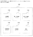
図1は、本発明の実施例による、画像におけるオブジェクトのエッジを抽出するための装置の例示的構造図である。 FIG. 1 is an exemplary structural diagram of an apparatus for extracting an edge of an object in an image according to an embodiment of the present invention.
図1に示すように、本発明の実施例による、画像におけるオブジェクトのエッジ抽出するため装置100は、位置確定ユニット110、第一方向確定ユニット120、第二方向確定ユニット130、勾配図取得ユニット140、勾配減衰ユニット150、及び抽出ユニット160を含む。
As shown in FIG. 1, an
図1に示すように、位置確定ユニット110は、画像におけるオブジェクトのエッジの起点及び終点を確定するために用いられる。
As shown in FIG. 1, the
そのうち、本発明の実施例による、画像におけるオブジェクトのエッジを抽出するための装置の具体的な実現方式では、上述の画像は、例えば、実物などのオブジェクトに対して撮影を行うことにより得られた画像、又は、例えば、文書などのオブジェクトに対してスキャンを行うことにより得られたスキャン画像であってもよい。 Among them, in the specific implementation method of the apparatus for extracting the edge of the object in the image according to the embodiment of the present invention, the above-mentioned image is obtained by photographing an object such as a real object, for example. It may be an image or a scanned image obtained by scanning an object such as a document.
次に、主に、文書に対してスキャンすることにより得られたスキャン画像を例として、本発明の実施例による、画像におけるオブジェクトのエッジを抽出するための装置100を詳しく説明する。この例では、上述のスキャン画像におけるオブジェクトのエッジは、文書の一つのエッジである。
Next, an
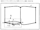
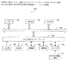
図2は、文書に対してスキャンを行うことにより得られたスキャン画像の一例を示す図である。図2に示すように、lは、文書dの一つのエッジ(即ち、真のエッジ)であり、P1及びP2は、それぞれ、エッジlの起点及び終点であり、ここでは、P1及びP2は、エッジlに対応する2つの文書コーナーである。なお、この2つの文書コーナー(即ち、エッジの起点及び終点)は、ユーザにより入力されてもよく、例えば、ユーザによりマウス又はタッチパネルなどの入力装置で入力されてもよく;或いは、上述の2つの文書コーナーは、幾つかの従来のコーナー抽出技術により取得されてもよいので、ここでは、その詳しい説明を省略する。なお、説明を簡潔にするために、図2には、文書dの内容を示していないが、実際の応用では、文書dには、例えば文字、画像などの各種の内容が含まれてもよい。 FIG. 2 is a diagram illustrating an example of a scanned image obtained by scanning a document. As shown in FIG. 2, l is one edge of document d (i.e., the true edge), and P1 and P2 are the start and end points of edge l, respectively, where P1 and P2 are Two document corners corresponding to edge l. Note that the two document corners (that is, the starting point and the ending point of the edge) may be input by the user, for example, may be input by the user using an input device such as a mouse or a touch panel; Since the document corner may be acquired by some conventional corner extraction techniques, a detailed description thereof is omitted here. For the sake of brevity, FIG. 2 does not show the contents of the document d. However, in actual application, the document d may include various contents such as characters and images. .
図2に示すエッジl1は、上述のコーナーP1及びP2の間に対して、従来のエッジ抽出技術(例えば、画像の勾配に基づくエッジ抽出技術)を利用することにより抽出されたエッジである。図2から分かるように、コーナーP1及びP2に基づいて抽出されたエッジl1は、真のエッジlとの間の差が比較的大きい。これは、文書dに含まれる文字、画像などのような内容の勾配(gradient)(以下、“内容勾配”と言う)がエッジ抽出に影響を与え、画像の勾配に基づいて抽出されたエッジに偏差が生じることによるものである。しかし、本発明の実施例による、画像におけるオブジェクトのエッジを抽出するための装置100を使用することにより、このような偏差を改善することができる。次に、図1及び図2を参照しながら、装置100における各構成ユニットの機能及び処理を続けて説明する。
The edge l1 shown in FIG. 2 is an edge extracted by using a conventional edge extraction technique (for example, an edge extraction technique based on an image gradient) between the above-described corners P1 and P2. As can be seen from FIG. 2, the difference between the edge l1 extracted based on the corners P1 and P2 and the true edge l is relatively large. This is because the gradient of content (hereinafter referred to as “content gradient”) such as characters and images included in document d affects edge extraction, and the extracted edges are based on the gradient of the image. This is because a deviation occurs. However, such deviations can be improved by using the
位置確定ユニット110は、さらに、上述のエッジの起点及び終点(図2に示す例では、文書コーナーP1及びP2)に関連する参考点の位置を確定するために用いられる。図2に示す例では、P3は、参考点の一例である。そのうち、参考点P3は、例えば、ユーザによりマウス又はタッチパネルなどの入力装置で入力されてもよい。
The
そのうち、ここで言う“起点”、“終点”及び“参考点”は、それぞれ、画像における単一の画素(ピクセル)点である。入力された“起点”、“終点”又は“参考点”としての点が複数の画素点を含む時に、その中から一つ(例えば、複数の画素点のうちの中心画素点)を選択して、対応する“起点”、“終点”又は“参考点”にしてもよい。 Among them, the “start point”, “end point”, and “reference point” mentioned here are each a single pixel point in the image. When the input “start point”, “end point” or “reference point” includes a plurality of pixel points, select one (for example, the center pixel point of the plurality of pixel points) from among them. The corresponding “start point”, “end point”, or “reference point” may be used.
図2に示すように、第一方向確定ユニット120は、エッジlの第一方向を確定するために用いられる。
As shown in FIG. 2, the first
そのうち、図2に示すように、本発明の実施例による、画像におけるオブジェクトのエッジを抽出するための装置の一例では、第一方向確定ユニット120は、次のようにエッジlの第一方向を推定することができ、即ち、コーナーP1及びP2の間の連結線(例えば、直線)lP1P2の勾配(slope)方向を取得し、この連結線lP1P2の勾配方向をエッジlの第一方向として確定する。
Among them, as shown in FIG. 2, in the example of the apparatus for extracting the edge of the object in the image according to the embodiment of the present invention, the first
また、本発明の実施例による、画像におけるオブジェクトのエッジを抽出するための装置の他の例では、第一方向確定ユニット120は、従来の例えば傾斜度推定方法によりエッジlの第一方向を取得してもよい。例えば、参考点P3の近傍で一つの画像ブロックを取得し、従来の方法により該画像ブロックの傾斜度(例えば、水平方向との夾角など)を求め、そして、該画像ブロックの傾斜度をエッジlの第一方向とする。
In another example of the apparatus for extracting an edge of an object in an image according to an embodiment of the present invention, the first
図2に示すように、第二方向確定ユニット130は、エッジlの第一方向に交差する第二方向kを確定するために用いられる。そのうち、第二方向kは、例えば、エッジlの第一方向に交差する任意の方向であってもよく、好ましくは、第二方向kは、エッジlの第一方向に垂直な方向である。なお、ここでいう「第一方向が第二方向に交差する」とは、第二方向に所在する直線が第一方向に所在する直線に交差する(即ち、夾角が0ではない)ことを指し、また、「第二方向が第一方向に垂直である」とは、第二方向に所在する直線と、第一方向に所在する直線との間の夾角が90度であることを指す。
As shown in FIG. 2, the second
また、勾配図取得ユニット140は、画像において、コーナーP1、コーナーP2及び参考点P3を含む第一領域を取得し、そして、上述の第一領域の勾配図を取得するために用いられる。そのうち、本発明の実施例による、画像におけるオブジェクトのエッジを抽出するための装置の具体的な実現方式では、上述の第一領域の形状は、矩形、正方形、円形及び楕円形などの形状のうちの任意の一種であってもよい。
The gradient
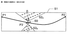
例えば、図2に示す例では、上述の第一領域は、コーナーP1、コーナーP2及び参考点P3を含む矩形領域S1であってもよく、そのうち、矩形領域S1の長さ方向は、例えば、コーナーP1及びP2の間の連結線lP1P2の勾配方向に沿ってもよい。 For example, in the example shown in FIG. 2, the first region described above may be a rectangular region S1 including a corner P1, a corner P2, and a reference point P3, and the length direction of the rectangular region S1 is, for example, a corner The connecting line l P1P2 between P1 and P2 may be along the gradient direction.
また、第一領域の勾配図を取得した後に、勾配減衰ユニット150は、参考点P3の、第二方向kに沿う両側のうちの少なくとも一つの側に、少なくとも一つの第二領域を確定し、そして、第一領域の勾配図において、第二領域の勾配に対して減衰を行うことができる。本発明の実施例による、画像におけるオブジェクトのエッジを抽出するための装置の一つの実現方式では、第一領域の勾配図が反対色処理(anti-color processing)を受けた後の勾配図である場合、勾配減衰ユニット150は、減衰後の勾配図における第二領域の勾配(gradient)の値を、減衰前の勾配図における第二領域の勾配の値よりも大きくしてもよく;また、該実現方式では、第一領域の勾配図が反対色処理を受けていない勾配図である場合、勾配減衰ユニット150は、減衰後の勾配図における第二領域の勾配(gradient)の値を、減衰前の勾配図における第二領域の勾配の値よりも小さくしてもよい。
Further, after obtaining the gradient diagram of the first region, the
また、第二領域は、三角形の領域、扇形の領域、帯状の領域、及び放物線形の領域などの各種の形状の領域のうちの任意の一種であってもよく、或いは、上述の各種の領域のうちの少なくとも2つの組み合わせ(重なり合い)であってもよい。なお、確定された第二領域は、参考点P3を含んでもよく、参考点P3を含まなくてもよく、好ましくは、第二領域は、参考点P3を含まない。 Further, the second region may be any one of various regions such as a triangular region, a sector region, a strip region, and a parabolic region, or the various regions described above. It may be a combination (overlap) of at least two of the above. The determined second region may include the reference point P3 and may not include the reference point P3. Preferably, the second region does not include the reference point P3.
そのうち、第二領域は、所定の形状及び/又はサイズを有してもよい。例えば、第二領域が三角形の領域である場合、該三角形の領域の頂角は、例えば、10度、30度又は他の所定の角度であってもよく、そのうち、例えば、図3Aに示すように、該頂角の、第二方向kの両側にある角α及び角βは、同じであってもよく(等しく設定されてもよく)、同じではなくてもよい(所定の比で設定されてもよく)(例えば、角αが10度で、角βが20度であってもよい)。 Among them, the second region may have a predetermined shape and / or size. For example, if the second region is a triangular region, the apex angle of the triangular region may be, for example, 10 degrees, 30 degrees, or some other predetermined angle, of which, for example, as shown in FIG. Further, the angle α and the angle β on both sides of the apex angle in the second direction k may be the same (may be set equal) or may not be the same (set at a predetermined ratio). (For example, the angle α may be 10 degrees and the angle β may be 20 degrees).
また、上述の頂角と、上述の角α及び角βとは、経験値又はテスト(実験)により確定されてもよい。 Moreover, the above-mentioned apex angle and the above-mentioned angle α and angle β may be determined by experience values or tests (experiment).
また、真のエッジの勾配が減衰により除去されることを防止するために、勾配減衰ユニット150は、第二領域と参考点P3との間に若干の余分(redundant)の領域を設置することができる。
In addition, in order to prevent the true edge gradient from being removed by attenuation, the
例えば、本発明の実施例による、画像におけるオブジェクトのエッジを抽出するための装置の具体的な実現方式では、第二領域が参考点P3の所定サイズの隣接する領域の外に位置するようにさせることができる。一例では、上述の所定サイズの隣接する領域は、参考点P3を含み且つ所定サイズを有する円形領域又は帯状領域などの領域であってもよい。 For example, in the specific implementation method of the apparatus for extracting the edge of the object in the image according to the embodiment of the present invention, the second area is positioned outside the adjacent area of the predetermined size of the reference point P3. be able to. In one example, the above-mentioned adjacent region of the predetermined size may be a region such as a circular region or a belt-like region including the reference point P3 and having the predetermined size.
本発明の実施例による、画像におけるオブジェクトのエッジを抽出するための装置の一つの実現方式では、第二領域の形状及び/又は位置は、ユーザの入力指令に基づいて調整され得る。例えば、ユーザが参考点P3の位置を入力する時に、参考点P3の、第二方向kに沿う両側に、点線枠の方式で、例えば三角形の領域、扇形の領域、帯状の領域及び放物線形の領域などの複数の異なる形状の領域が示され、ユーザによりそのうちの少なくとも一つの領域を選択して第二領域としてもよい。また、幾つかの例では、ユーザにより手動で上述の第二領域の形状及び/又は位置を調整することができ、例えば、選定された第二領域としての三角形領域の辺長、頂角などに対して手動調整を行うことにより、最適な処理効果を実現することができる。 In one implementation of the apparatus for extracting an edge of an object in an image according to an embodiment of the present invention, the shape and / or position of the second region can be adjusted based on a user input command. For example, when the user inputs the position of the reference point P3, on both sides of the reference point P3 along the second direction k, for example, a triangular frame, a fan-shaped region, a strip-shaped region, and a parabolic shape A plurality of regions having different shapes such as a region are shown, and at least one of the regions may be selected by the user as the second region. In some examples, the user can manually adjust the shape and / or position of the above-described second region. For example, the side length and apex angle of the triangular region as the selected second region can be adjusted. On the other hand, an optimum processing effect can be realized by performing manual adjustment.
図3A及び図3Bは、それぞれ、図2に示すような第一領域S1の勾配図を示している。なお、一般的には、直接取得された画像の勾配図(以下、「反対色処理を受けていない勾配図」又は「正常勾配図」という)の背景の勾配の値が通常0又は0に近い値である。図3A及び図3Bに示す勾配図は、上述の直接取得された第一領域S1の勾配図に対して反対色処理を行うことにより得られた勾配図(255から、正常勾配図における各画素点の勾配の値をそれぞれ引いて(マイナスして)、得られた勾配の値により生成された勾配図は、上述の正常勾配図の反対色勾配図である)(以下、「反対色処理を受けている勾配図」又は「反対色勾配図」という)であるので、図3A及び図3Bに示す勾配図における背景の勾配の値は255又は255に近い値である。 3A and 3B show gradient diagrams of the first region S1 as shown in FIG. 2, respectively. In general, the value of the gradient of the background of the gradient diagram of the directly acquired image (hereinafter referred to as “gradient diagram not subjected to the opposite color process” or “normal gradient diagram”) is usually close to 0 or 0 Value. The gradient diagrams shown in FIGS. 3A and 3B are gradient diagrams (from 255, each pixel point in the normal gradient diagram obtained by performing the opposite color process on the gradient map of the first region S1 obtained directly above. The gradient generated by the gradient values obtained by subtracting (minus) each of the gradient values is the opposite color gradient diagram of the above normal gradient diagram) (hereinafter referred to as “reverse color processing”). The gradient value of the background in the gradient diagrams shown in FIGS. 3A and 3B is 255 or close to 255.
一例では、図3Aに示すように、勾配減衰ユニット150は、まず、参考点P3の所定サイズの隣接する領域、例えば、図3Aにおいて、参考点P3を円心とする、所定サイズを有する円形の隣接する領域S0を確定することができ、そのうち、円形の隣接する領域S0のサイズは、例えば、経験又は実際のニーズに応じて設定されてもよい。その後、勾配減衰ユニット150は、それぞれ、参考点P3の、第二方向kに沿う両側に、三角形領域、即ち、S2A及びS2Bを確定して第二領域とすることができる。そのうち、三角形領域S2A及びS2Bは、それぞれ、参考点P3の円形の隣接する領域S0の外に位置する。第二領域確定後、勾配減衰ユニット150は、第一領域S1において、第二領域(即ち、三角形領域S2A及びS2B)の勾配に対して減衰を行い、即ち、減衰後の第二領域の勾配を、減衰前のそれよりも大きくさせる。一例では、三角形領域S2A及びS2Bの勾配を増大させてもよい(例えば、三角形領域S2A及びS2Bの元の勾配が20であれば、減衰後の三角形領域S2A及び三角形領域S2Bの勾配が100又はそれよりも高い値であってもよい)。他の例では、三角形領域S2A及びS2Bの勾配を直接に255に設定してもよい。
In one example, as shown in FIG.3A, the
他の例では、図3Bに示すように、勾配減衰ユニット150は、まず、参考点P3の所定サイズの隣接する領域、例えば、図3Bにおいて、参考点P3を中心とする、所定サイズを有する帯状の隣接する領域S0’を確定することができ、該帯状隣接する領域S0’の長さ方向は、エッジlの第一方向に沿う。そのうち、参考点P3の帯状の隣接する領域S0’のサイズは、例えば、経験又は実際のニーズに応じて設定されてもよい。その後、勾配減衰ユニット150は、それぞれ、参考点P3の、第二方向kに沿う両側に、帯状領域、即ち、S3A和S3Bを確定して第二領域とすることができる。同様に、帯状領域S3A及びS3Bは、それぞれ、参考点P3の帯状の隣接する領域S0’の外に位置し、また、減衰後の第二領域の勾配は、減衰前のそれよりも大きくさせられる。なお、帯状領域S3A及びS3Bの勾配に対して減衰を行う具体例については、上述の図3Aに示す三角形領域S2A及びS2Bに対して減衰を行う具体例を参照することができる、ここでは、その記載を省略する。
In another example, as shown in FIG.3B, the
また、他の例では、第一領域の勾配図が正常勾配図(反対色処理を受けていないもの)であれば、勾配減衰ユニット150により、減衰後の第二領域の勾配を、減衰前のそれよりも小さくさせることができる。一例では、第二領域の勾配を減少させてもよい(例えば、第二領域の元の勾配が200であれば、減衰後の第二領域の勾配は100又はそれよりも低い値であってもよい)。他の例では、第二領域の勾配を直接に0に設定してもよい。
In another example, if the gradient diagram of the first region is a normal gradient diagram (not subjected to the opposite color process), the
また、本発明の実施例による、画像におけるオブジェクトのエッジを抽出するための装置100の他の実現方式では、勾配減衰ユニット150は、参考点P3の、第二方向kに沿う両側のうちの一つの側に、一つの第二領域を確定してもよい。例えば、図3Aを参照するに、勾配減衰ユニット150は、参考点P3の、第二方向kに沿う一つの側に、三角形領域S2A又は三角形領域S2Bを確定して第二領域とし、その後、第一領域の勾配図において、該第二領域の勾配に対して上述に類似する減衰を行ってもよい。
Also, in another implementation of the
図3Aを参照するに、一例では、文書dの内に内容が存在し、文書dの外に内容が存在しない場合、勾配減衰ユニット150は、参考点P3の、第二方向kに沿う一つの側に、三角形領域S2Aを確定して第二領域とし(この場合、第二領域は、図3Aにおける三角形領域S2Bを含まない)、そして、第一領域S1において、上述の方式で第二領域S2Aの勾配に対して減衰を行ってもよい。また、他の例では、文書dの内におけるページのマージンの近傍に例えば内容が存在せず、文書dの外に内容が存在する場合、勾配減衰ユニット150は、参考点P3の、第二方向kに沿う他の側に、三角形領域S2Bを確定して第二領域とし(この場合、第二領域は、図3Aにおける三角形領域S2Aを含まない)、そして、第一領域S1において、上述の方式で第二領域S2Bの勾配に対して減衰を行ってもよい。
Referring to FIG. 3A, in one example, if the content exists in document d and there is no content outside document d, the
減衰後の勾配図を取得した後に、抽出ユニット160は、コーナーP1及びP2の間に対してエッジ抽出を行い、文書dのエッジを取得するために用いられる。
After obtaining the attenuated gradient diagram, the
図4は、図1に示す抽出ユニット160の例示的な構造図である。図4に示すように、本発明の実施例による、画像におけるオブジェクトのエッジを抽出するための装置の一つの実現方式では、抽出ユニット160は、勾配設定サブユニット410及び抽出サブユニット420を含んでもよい。
FIG. 4 is an exemplary structural diagram of the
そのうち、該実現方式では、勾配設定サブユニット410は、参考点の勾配を設置することができ、そして、抽出サブユニット420は、エッジ追跡方法(例えば、動的計画法のアルゴリズム(dynamic programming algorithm))を用いて、上述の起点及び終点の間からエッジを抽出することができる。
Among them, in the realization scheme, the
一例では、第一領域の勾配図が反対色勾配図(反対色処理を受けているもの)である場合、参考点の勾配の値を、第一所定閾値よりも小さい値に設定してもよい(例えば、0よりも小さい負数、例えば、-999に設定してもよい)。他の例では、第一領域の勾配図が正常勾配図(反対色処理を受けていないもの)である場合、参考点の勾配の値を、第二所定閾値によりも大きい値(例えば、255よりも大きい正数、例えば、999に設定してもよい)。 In one example, when the gradient diagram of the first region is an opposite color gradient diagram (that has been subjected to the opposite color process), the gradient value of the reference point may be set to a value smaller than the first predetermined threshold value. (For example, it may be set to a negative number smaller than 0, for example, -999). In another example, when the gradient diagram of the first region is a normal gradient diagram (not subjected to the opposite color process), the gradient value of the reference point is set to a value larger than the second predetermined threshold (for example, more than 255). May be set to a large positive number, for example, 999).
このようにして、抽出サブユニット420により上述の起点及び終点の間から抽出されたエッジが上述の参考点を通過する可能性を大きくさせることができる。
In this way, it is possible to increase the possibility that the edge extracted from between the start point and the end point by the
図2に示すように、l2は、本発明の実施例による、画像におけるオブジェクトのエッジを抽出するための装置により抽出されたエッジである。図2から分かるように、l1に比べ、本発明の実施例による、画像におけるオブジェクトのエッジを抽出するための装置により抽出されたエッジl2は、真のエッジlにより近いので、その抽出精度は、比較的に高い。 As shown in FIG. 2, l2 is an edge extracted by an apparatus for extracting an edge of an object in an image according to an embodiment of the present invention. As can be seen from FIG. 2, since the edge l2 extracted by the device for extracting the edge of the object in the image according to the embodiment of the present invention is closer to the true edge l than the l1, the extraction accuracy is Relatively high.
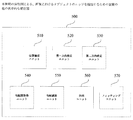
また、図5は、本発明の実施例による、画像におけるオブジェクトのエッジを抽出するための装置の他の構造図である。図5に示すように、本発明の実施例による、画像におけるオブジェクトのエッジを抽出するための装置500は、位置確定ユニット510、第一方向確定ユニット520、第二方向確定ユニット530、勾配図取得ユニット540、勾配減衰ユニット550、及び抽出ユニット560を含んでもよく、また、装置500は、さらに、フィッティング(当てはめ)ユニット570を含んでもよい。そのうち、位置確定ユニット510、第一方向確定ユニット520、第二方向確定ユニット530、勾配図取得ユニット540、勾配減衰ユニット550、及び抽出ユニット560は、図1に示す装置100中の対応するユニットと同じ構造及び機能を有し、類似する技術的効果を達成することができるので、ここでは、それらについての詳しい説明を省略する。
FIG. 5 is another structural diagram of an apparatus for extracting an edge of an object in an image according to an embodiment of the present invention. As shown in FIG. 5, according to an embodiment of the present invention, an
図5に示すように、フィッティングユニット570は、抽出ユニット560により取得されたオブジェクトのエッジに対してフィッティングを行うことができる。そのうち、一例では、上述のオブジェクトのエッジに対してフィッティングを行うプロセスにおいて、参考点のウェイト(重み)を、第三所定閾値よりも大きい値に設定してもよい。
As shown in FIG. 5, the
このようにして、フィッティングユニット570は、抽出ユニット560により取得されたオブジェクトのエッジに対して平滑化を行うことができる。また、全体的なモデルを考慮しているので、処理後のオブジェクトのエッジは、全体的な平滑性を有し実際状況に符合しているものである。また、異なる実際状況に応じて、異なるフィッティングアルゴリズムを採用してもよい。例えば、文書エッジが直線であることが既知のことである場合、直線フィッティング(近似)アルゴリズムを採用して、抽出ユニット560により取得されたオブジェクトのエッジに対してフィッティングを行ってもよい。また、例えば、文書エッジが曲線であることが既知のことである場合、高次多項式フィッティングアルゴリズムを採用して、抽出ユニット560により取得されたオブジェクトのエッジに対してフィッティングを行ってもよい。
In this way, the
なお、上述の第一、第二及び第三所定閾値は、経験値又はテスト(実験)の方式で確定することができるので、ここでは、その詳しい説明を省略する。 Note that the first, second, and third predetermined threshold values described above can be determined by an experience value or a test (experiment) method, and thus detailed description thereof is omitted here.
また、本発明の上述の実施例によれば、参考点の数が1つである場合に、上述のエッジ抽出を完成させることができる。しかし、本発明の他の実施例では、参考点の数が複数であってもよく、このようにして、抽出されたエッジの精度をより高くさせることができる。参考点の数が複数である場合に、例えば、ユーザが参考点を入力する度に、一回のエッジ抽出を完成させ、そして、現在に抽出されているエッジをユーザに見せることができ、ユーザは、現在のエッジの正確さに基づいて、次の参考点を入力するかどうかを判断することができる。そのうち、行われる各回のエッジ抽出は、その現在に存在する全ての参考点を利用して実現され、即ち、現在に存在する各参考点の近傍にそれぞれ少なくとも一つの第二領域を確定し、そして、各第二領域の勾配に対して減衰を行い、エッジ抽出を完成させることである。 Further, according to the above-described embodiment of the present invention, when the number of reference points is one, the above-described edge extraction can be completed. However, in another embodiment of the present invention, the number of reference points may be plural, and thus the accuracy of the extracted edge can be further increased. When there are a plurality of reference points, for example, every time the user inputs a reference point, one edge extraction can be completed and the currently extracted edge can be shown to the user. Can determine whether to input the next reference point based on the accuracy of the current edge. Of these, each round of edge extraction is accomplished using all of the currently existing reference points, i.e., at least one second region is defined in the vicinity of each currently existing reference point, and In other words, the gradient of each second region is attenuated to complete edge extraction.
本発明の実施例による、画像におけるオブジェクトのエッジを抽出するための装置の一例では、参考点の数が複数である場合、上述の複数の参考点のうち、距離が所定距離範囲内(例えば、3つの画素点内)にある2つの参考点が存在すれば、勾配設定サブユニット410により、次のような方式で、この2つの参考点の間の連結線上の各点の勾配を設定してもよく、即ち、第一領域の勾配図が反対色勾配図である場合、距離が所定距離範囲内にある上述の2つの参考点の勾配を、0のような第三所定隣接領域範囲内の値(例えば、(-10、10)のうちの任意の値)に設定してもよく;第一領域の勾配図が正常勾配図である場合、距離が所定距離範囲内にある上述の2つの参考点の勾配を、255のような第四所定隣接領域範囲内の値(例えば、(245、265)のうちの任意の値)に設定してもよい。このようにして、抽出サブユニット420により抽出されたエッジがこの2つの参考点間の連結線を通過する可能性を大きくさせることができる。
In an example of an apparatus for extracting an edge of an object in an image according to an embodiment of the present invention, when there are a plurality of reference points, the distance is within a predetermined distance range (for example, If there are two reference points (within three pixel points), the
なお、本発明の実施例による、画像におけるオブジェクトのエッジを抽出するための装置100及び500における各ユニットの操作(処理)は、必ずしも上述の前後の順序に従って行う必要がなく、各ユニットの機能を実現できれば、他の方式で行ってもよい。
Note that the operation (processing) of each unit in the
また、本発明の上述の実施例では、文書を画像中のオブジェクトの一例として説明を行ったが、理解すべきは、本発明の他の実施例では、上述の画像中のオブジェクトは、例えば実物などの他のオブジェクトであってもよく、エッジの起点及び終点は、コーナーP1及びP2以外の他の類型の起点及び終点であってもよいとのことである。 In the above-described embodiment of the present invention, a document is described as an example of an object in an image. However, it should be understood that in another embodiment of the present invention, an object in the above-described image is, for example, a real object. The edge starting point and end point may be other types of starting points and end points other than the corners P1 and P2.
上述の説明から分かるように、本発明の実施例による、画像におけるオブジェクトのエッジを抽出するための装置は、画像の勾配図において、参考点近傍の内容勾配に対し減衰を行い、抽出されたエッジが上述の参考点を通過する可能性を大きくさせることができるので、エッジ抽出の精度を向上させることができる。 As can be seen from the above description, the apparatus for extracting the edge of an object in an image according to an embodiment of the present invention attenuates the content gradient near the reference point in the gradient diagram of the image, and extracts the extracted edge. Can increase the possibility of passing through the above-mentioned reference points, so that the accuracy of edge extraction can be improved.
また、エッジの起点及び終点が確定されている場合、幾つかの制御点を採用して曲線全体を代表するような従来のエッジ抽出技術に比べ、本発明の実施例による、画像におけるオブジェクトのエッジを抽出するための装置は、一つのみの参考点の位置を把握すれば、より正確なエッジを抽出することができ、また、ユーザによる複数回の手動調整をも要しないので、処理効率を向上させることができるのみならず、ユーザよる使用にも便利である。 In addition, when the start and end points of an edge are fixed, the edge of an object in an image according to the embodiment of the present invention is compared with a conventional edge extraction technique that employs several control points to represent the entire curve. Since the device for extracting only one reference point can extract a more accurate edge and does not require multiple manual adjustments by the user, the processing efficiency can be improved. Not only can it be improved, it is also convenient for use by the user.
また、本発明の実施例は、さらに、画像におけるオブジェクトのエッジを抽出するための方法を提供する。次に、図6を参照しながら、画像におけるオブジェクトのエッジを抽出するための上述の方法の例示的な処理プロセスを詳しく説明する。 Also, embodiments of the present invention further provide a method for extracting object edges in an image. Next, an exemplary processing process of the above-described method for extracting the edge of an object in an image will be described in detail with reference to FIG.
図6は、発明の実施例による、画像におけるオブジェクトのエッジを抽出するための方法の例示的な処理のフローチャートである。 FIG. 6 is a flowchart of an exemplary process of a method for extracting an edge of an object in an image according to an embodiment of the invention.
図6に示すように、本発明の実施例による、画像におけるオブジェクトのエッジを抽出するための方法の例示的な処理プロセス600は、ステップS610にて始まり、それから、ステップS620を実行する。
As shown in FIG. 6, an
ステップS620では、画像におけるオブジェクトのエッジの起点及び終点を確定し、そして、上述の起点及び上述の終点に関連する参考点の位置を確定する。それから、ステップS630を実行する。 In step S620, the start point and end point of the edge of the object in the image are determined, and the positions of the reference points related to the start point and the end point are determined. Then, step S630 is executed.
そのうち、上述のオブジェクトは、例えば、文書、又は、例えば実物などの他の類型のオブジェクトであってもよい。 Among them, the above-described object may be, for example, a document or another type of object such as a real object.
ステップS630では、上述のエッジの第一方向を確定する。それから、ステップS640を実行する。 In step S630, the first direction of the edge is determined. Then, step S640 is executed.
一つの具体的な実現方式では、上述の起点及び上述の終点の間の連結線(例えば、直線)の勾配(slope)方向を取得し、そして、該勾配方向を上述のエッジの第一方向として確定してもよい。或いは、上述の他の方式で、上述のエッジの第一方向を確定してもよい。 In one specific implementation method, a slope direction of a connecting line (for example, a straight line) between the above-mentioned starting point and the above-mentioned end point is obtained, and the slope direction is set as the first direction of the above-mentioned edge. It may be confirmed. Alternatively, the first direction of the edge may be determined by another method described above.
ステップS640では、上述のエッジの第一方向に交差する(例えば、垂直な)第二方向を確定する。それから、ステップS650を実行する。 In step S640, a second direction (eg, perpendicular) that intersects the first direction of the edge described above is determined. Then, step S650 is executed.
ステップS650では、上述の画像において、上述の起点、上述の終点、及び上述の参考点を含む第一領域を確定し、そして、上述の第一領域の勾配図を取得する。それから、ステップS660を実行する。 In step S650, a first region including the above-described starting point, the above-described end point, and the above-described reference point is determined in the above-described image, and a gradient diagram of the above-described first region is acquired. Then, step S660 is executed.
ステップS660では、上述の参考点の、第二方向に沿う両側のうちの少なくとも一つの側に、少なくとも一つの第二領域を確定する。それから、ステップS670を実行する。 In step S660, at least one second region is determined on at least one side of both sides of the reference point along the second direction. Then, step S670 is executed.
そのうち、第二領域は、三角形の領域、扇形の領域、帯状の領域、及び放物線形の領域などの各種の形状の領域のうち任意の一種であってもよく、また、上述の各種の領域のうち少なくとも2つの組み合わせ(重なり合い)であってもよい。 Among them, the second region may be any kind of regions of various shapes such as a triangular region, a sector region, a strip region, and a parabolic region, and the second region It may be a combination (overlap) of at least two of them.
また、第二領域は、参考点の所定サイズの隣接する領域の外に位置してもよい。そのうち、参考点の所定サイズの隣接する領域は、例えば、参考点を含み且つ所定サイズを有する円形の領域であってもよく、又は、参考点を含み且つ長さがエッジの第一方向に沿って延伸し且つ所定サイズを有する帯状の領域であってもよい。参考点の所定サイズの隣接する領域の具体的な説明については、上述の内容を参照することができるので、ここでは、その詳しい説明を省略する。 Further, the second area may be located outside an adjacent area having a predetermined size of the reference point. Among them, the adjacent region of the reference point having the predetermined size may be, for example, a circular region including the reference point and having the predetermined size, or including the reference point and having a length along the first direction of the edge. It may be a belt-like region that is stretched and has a predetermined size. Since the above-mentioned content can be referred to for the specific description of the adjacent region of the reference point having the predetermined size, the detailed description thereof is omitted here.
ステップS670では、上述の勾配図において、上述の第二領域の勾配に対して減衰を行い、そして、減衰後の勾配図に基づいて、上述の起点及び上述の終点の間に対してエッジ抽出を行い、上述のオブジェクトのエッジを取得する。それから、ステップS680を実行する。 In step S670, attenuation is performed on the gradient of the second region in the gradient diagram described above, and edge extraction is performed between the start point and the end point based on the gradient diagram after attenuation. To obtain the edge of the object. Then, step S680 is executed.
そのうち、ステップS670では、上述の勾配図において、第二領域の勾配に対して減衰を行ってもよい。そのうち、減衰のプロセスについては、図1に基づいて上述した勾配減衰ユニット150の処理及び操作を参照することができるので、ここでは、その詳しい説明を省略する。
Among them, in step S670, attenuation may be performed on the gradient of the second region in the above gradient diagram. Among them, regarding the attenuation process, since the processing and operation of the
また、ステップS670では、減衰後の勾配図に基づいて、上述の起点及び上述の終点の間に対してエッジ抽出を行う処理については、図4に基づいて上述した勾配設定サブユニット410及び抽出サブユニット420の処理(操作)を参照することができるので、ここでは、その詳しい説明を省略する。
Further, in step S670, the processing for performing edge extraction between the above-described starting point and the above-mentioned end point based on the gradient diagram after attenuation is performed using the
処理プロセス600は、ステップS680にて終了する。
また、本発明の実施例による、画像におけるオブジェクトのエッジを抽出するための方法の他の例示的な処理プロセスでは、ステップS670には、上述の処理の他に、取得されたオブジェクトのエッジに対してフィッティングを行う処理を含んでもよい。該フィッティング処理については、図5に基づいて上述したフィッティングユニット570の処理(操作)を参照することができるので、ここでは、その詳しい説明を省略する。
In addition, in another exemplary processing process of the method for extracting an edge of an object in an image according to an embodiment of the present invention, in step S670, in addition to the above-described processing, the acquired object edge is processed. And a process of performing fitting may be included. Regarding the fitting process, the process (operation) of the
なお、実際の処理では、上述の各ステップの処理は、必ずしも上述の順序に従って行う必要がなく、他の方式で行ってもよい。 In actual processing, the processing of each step described above does not necessarily have to be performed in the order described above, and may be performed by another method.
上述の説明から分かるように、本発明の実施例による、画像におけるオブジェクトのエッジを抽出するための方法は、画像の勾配図において、参考点近傍の内容勾配に対し減衰を行い、抽出されたエッジが上述の参考点を通過する可能性を大きくさせることができるので、エッジ抽出の精度を向上させることができる
また、エッジの起点及び終点が確定されている場合、幾つかの制御点を採用して曲線全体を代表するような従来のエッジ抽出技術に比べ、本発明の実施例による、画像におけるオブジェクトのエッジを抽出するための方法は、一つのみの参考点の位置を把握すれば、より正確なエッジを抽出することができ、また、ユーザによる複数回の手動調整を要しないので、処理効率を向上させることができるのみならず、ユーザよる使用にも便利である。
As can be seen from the above description, the method for extracting the edge of an object in an image according to an embodiment of the present invention attenuates the content gradient near the reference point in the gradient diagram of the image and extracts the extracted edge. Can increase the possibility of passing through the above-mentioned reference points, so that the accuracy of edge extraction can be improved. Also, when the start and end points of an edge are determined, several control points are adopted. Compared with the conventional edge extraction technique that represents the entire curve, the method for extracting the edge of the object in the image according to the embodiment of the present invention is more effective if the position of only one reference point is grasped. Accurate edges can be extracted, and multiple manual adjustments by the user are not required, so that not only can the processing efficiency be improved, but also the user can use it. It is also convenient for use.
また、本発明の実施例は、さらに、電子設備を提供する。該電子設備は、上述のような、画像におけるオブジェクトのエッジを抽出するための装置を含む。該電子設備は、例えば、次のような装置のうちの任意の一種であってもよく、即ち、スキャナー、カメラ、コンピュータ、携帯電話、タブレットPC、及び、PDA(personal digital assistant)などである。該電子設備は、上述のような、画像におけるオブジェクトのエッジを抽出するための装置の有益な効果及び利点を有する。 The embodiments of the present invention further provide electronic equipment. The electronic equipment includes a device for extracting an edge of an object in an image as described above. The electronic equipment may be, for example, any one of the following devices: a scanner, a camera, a computer, a mobile phone, a tablet PC, and a personal digital assistant (PDA). The electronic equipment has the beneficial effects and advantages of an apparatus for extracting object edges in an image as described above.
本発明の実施例によれば、画像におけるオブジェクトのエッジを抽出するための上述のような装置、方法及び電子設備は、エッジ抽出の精度を改善することができ、ユーザによる複数回の手動調整を要せず、処理効率を向上させることができ、及び、ユーザによる使用に便利であるとのような効果のうちの少なくとも一つを得ることができる。 According to an embodiment of the present invention, the apparatus, method and electronic equipment as described above for extracting the edge of an object in an image can improve the accuracy of edge extraction, and multiple manual adjustments by a user. The processing efficiency can be improved, and at least one of the advantages such as being convenient for use by the user can be obtained.
本発明の実施例による上述のような、画像におけるオブジェクトのエッジを抽出するための装置における各構成ユニット、サブユニットなどは、ソフトウェア、ファームウェア、ハードウェア又はそれらの任意の組み合わせの方式で実現されてもよい。ソフトウェア又はファームウェアにより実現される場合は、記憶媒体又はネットワークから、専用ハードウェア構造を有する装置(例えば、図7に示す汎用装置700)に、このソフトウェア又はファームウェアを構成するプログラムをインストールすることができ、この装置は、各種のプログラムがインストールされている時に、上述の各構成ユニットやサブユニットの各種の機能を行うことができる。
Each component unit, subunit, etc. in the apparatus for extracting an edge of an object in an image as described above according to an embodiment of the present invention is realized by a method of software, firmware, hardware, or any combination thereof. Also good. When implemented by software or firmware, a program constituting the software or firmware can be installed from a storage medium or a network to a device having a dedicated hardware structure (for example, the general-
図7は、本発明の実施例による、画像におけるオブジェクトのエッジを抽出するための装置及び方法を実現し得る一つの例示的な情報処理装置のハードウェア配置図である。 FIG. 7 is a hardware layout diagram of an exemplary information processing apparatus capable of realizing an apparatus and method for extracting an edge of an object in an image according to an embodiment of the present invention.
図7では、中央処理ユニット(CPU)701は、ROM 702に記憶されているプログラム、又は、記憶部708からRAM 703にロードされているプログラムに基づいて、各種の処理を行う。RAM 703は、必要に応じて、CPU 701が各種の処理などを実行する時に必要なデータを記憶する。CPU 701、ROM 702及びRAM 703は、バス704により互いに接続される。入力/出力インタフェース705もバス704に接続される。
In FIG. 7, the central processing unit (CPU) 701 performs various processes based on a program stored in the
また、入力/出力インタフェース705に接続されるのは、入力部706(キーボード、マウスなどを含み)、出力部707(例えばCRT、LCDのような表示器及びスピーカーなどを含み)、記憶部708(ハードディスクなどを含み)、通信部709(例えばLANカード、モデムなどのネットワークアクセスカードを含み)をも含む。通信部709は、ネットワーク、例えばインターネットを介して通信処理を行う。必要に応じて、ドライブ710も入力/出力インタフェース705に接続され得る。取り外し可能な媒体711、例えば磁気ディスク、光ディスク、光磁気ディスク、半導体記憶装置なども、必要に応じてドライブ710に取り付けされてもよく、その中から読み出されたコンピュータプログラムは、必要に応じて記憶部708にインストールされ得る。
The input /
ソフトウェアにより上述の一連の処理を実現する場合、ネットワーク、例えばインターネット、又は、記憶媒体、例えば取り外し可能な媒体711からソフトウェアを構成するプログラムをインストールしてもよい。
When the above-described series of processing is realized by software, a program constituting the software may be installed from a network such as the Internet or a storage medium such as a
なお、当業者が理解すべきは、このような記憶媒体は、中にプログラムが記憶されており、ユーザにプログラムを提供するよう装置と独立して配られる図7に示すような取り外し可能な媒体711に限定されない。取り外し可能な媒体711の例としては、磁気ディスク(フロッピーディスク(登録商標)を含む)、光ディスク(CD−ROM及びDVDを含む)、光磁気ディスク(MD(登録商標)を含む)、及び半導体メモリを含む。或いは、記憶媒体はROM 702、記憶部708に含まれるハードディスクなどであってもよく、それらにはプログラムが記憶されており、且つそれらを含む装置とともにユーザに配られてもよい。
It should be understood by those skilled in the art that such a storage medium has a program stored therein and is a removable medium as shown in FIG. 7 distributed independently of the apparatus so as to provide the program to the user. It is not limited to 711. Examples of
また、本開示は、マシン(例えば、コンピュータ)読取可能な指令コードからなるプログラムプロダクトにも関する。この指令コードは、マシンに読み取られて実行される時に、上述の実施例による処理方法を実行することができる。それ相応に、上述のマシン読取可能な指令コードからなるプログラムプロダクトを記憶している記憶媒体も本開示に含まれている。このような記憶媒体は、磁気ディスク(フロッピーディスク)、光ディスク、光磁気ディスク、メモリカード、メモリメモリスティックなどを含むが、これらに限定されない。 The present disclosure also relates to a program product comprising machine (eg, computer) readable instruction code. When this command code is read by a machine and executed, the processing method according to the above-described embodiment can be executed. Accordingly, the present disclosure also includes a storage medium that stores a program product that includes the above-described machine-readable instruction code. Such storage media include, but are not limited to, magnetic disks (floppy disks), optical disks, magneto-optical disks, memory cards, memory memory sticks, and the like.
また、本開示の一つの図面又は一つの実施例に記載の要素及び特徴は、一つ以上の他の図面又は実施例に示す要素及び特徴と組み合わせることができる。 Also, elements and features described in one drawing or embodiment of the present disclosure may be combined with elements and features shown in one or more other drawings or embodiments.
また、上述の一連の処理を行うステップは、上述に説明した順序に従って時間順に行ってもよいが、必ずしも時間順に行う必要がない。一部のステップは、並行又は互いに独立で行ってもよい。よって、本明細書に記載の方法の実行順序は、本発明の技術的範囲を限定しない。 In addition, the steps of performing the above-described series of processing may be performed in time order according to the order described above, but are not necessarily performed in time order. Some steps may be performed in parallel or independently of each other. Therefore, the execution order of the methods described herein does not limit the technical scope of the present invention.
また、本開示による上述の方法の各処理プロセスは、各種のマシン読み取り可能な記憶媒体に記憶されているコンピュータ実行可能なプログラムで実現され得ることも明らかである。 It is also obvious that each processing process of the above-described method according to the present disclosure can be realized by a computer-executable program stored in various machine-readable storage media.
また、本開示の目的は、次の方法で実現されてもよい。即ち、上述の実行可能なプログラムコードを記憶している記憶媒体を直接又は間接的にシステム又は装置に提供し、且つ、このシステム又は装置内のコンピュータ又はCPUは、上述のプログラムコードを読み出して実行する。このとき、システム又は装置はプログラムを実行する機能を有すれば、本発明の実施形態はプログラムに限定されず、且つ、このプログラムは任意の形式であってもよく、例えば、オブジェクトプログラム、インタープリター実行可能なプログラム、又は、オペレーティングシステムへのスクリプトプログラムであってもよい。 The object of the present disclosure may be realized by the following method. That is, a storage medium storing the above executable program code is provided directly or indirectly to the system or apparatus, and the computer or CPU in the system or apparatus reads out and executes the above program code. To do. At this time, as long as the system or apparatus has a function of executing the program, the embodiment of the present invention is not limited to the program, and the program may be in any format, for example, an object program, an interpreter. It may be an executable program or a script program for the operating system.
上述のマシン読み取り可能な記憶媒体は、各種の記憶器及び記憶ユニット、半導体装置、光、磁気及び光磁気ディスクのような磁気ディスクユニット、及び情報記憶に適する他の媒体等を含むが、これらに限定されない。 The machine-readable storage medium described above includes various storage devices and storage units, semiconductor devices, magnetic disk units such as optical, magnetic and magneto-optical disks, and other media suitable for information storage. It is not limited.
また、クライントコンピュータは、インターネットを介して、対応するサーバに接続し、且つ、本発明によるコンピュータプログムラコードをコンピュータにダウンロードしてインストールし、それから、このプログラムを実行することにより、本発明を実現することもできる。 In addition, the client computer connects to a corresponding server via the Internet, downloads and installs the computer program code according to the present invention to the computer, and then executes the program to realize the present invention. You can also
最後に説明すべきは、本文では、例えば、「第一」及び「第二」などのような関係を表す語は、1つの実体又は操作と、もう1つの実体又は操作とを区分するためだけのものであり、これらの実体又は操作の間にそのような実際の関係又は順序が存在するとの意味又は示唆を有しない。また、「含む」、「有する」などのような語又はその他の変形語は、非排他的な「含む」を包括するために用いられ、これにより、一連の要素を含むプロセス、方法、物品又は装置は、これらの要素だけでなく、明記されていない他の要素をも含んでもよく、或いは、このプロセス、方法、物品又は装置が所有する固有の要素をも含むものである。より多くの限定が無い場合、「・・・を含む」という語句で限定される要素は、この要素を含むプロセス、方法、物品又は装置に存在する他の同じ要素を排除しない。 Lastly, it should be explained that in the text, for example, terms such as “first” and “second” are only used to distinguish one entity or operation from another. And has no meaning or suggestion that there is such an actual relationship or order between these entities or operations. Also, terms such as “including”, “having”, or other variations are used to encompass non-exclusive “including”, whereby a process, method, article or The device may include not only these elements, but also other elements not specified, or may include unique elements owned by the process, method, article or device. In the absence of more limitations, an element defined by the phrase “including” does not exclude other identical elements present in the process, method, article, or apparatus containing the element.
また、上述の各実施例を含む実施形態に関し、更に以下の付記を開示する。 Moreover, the following additional remarks are disclosed regarding the embodiment including each of the above-described examples.
(付記1)
画像におけるオブジェクトのエッジを抽出するための装置であって、
前記画像における前記オブジェクトのエッジの起点及び終点を確定し、前記起点及び前記終点に関連する参考点の位置を確定するための位置確定ユニット;
前記エッジの第一方向を確定するための第一方向確定ユニット;
前記第一方向に交差する第二方向を確定するための第二方向確定ユニット;
前記画像において、前記起点、前記終点及び前記参考点を含む第一領域を確定し、前記第一領域の勾配図を取得するための勾配図取得ユニット;
前記第二方向に沿う前記参考点の両側のうちの少なくとも一つの側に、少なくとも一つの第二領域を確定し、前記勾配図において、前記第二領域の勾配に対して減衰を行うための勾配減衰ユニット;及び
減衰後の前記勾配図に基づいて、前記起点と前記終点との間に対してエッジ抽出を行い、前記オブジェクトのエッジを取得するための抽出ユニットを含む、装置。
(Appendix 1)
An apparatus for extracting an edge of an object in an image,
A position determination unit for determining a start point and an end point of the edge of the object in the image, and determining a position of a reference point related to the start point and the end point;
A first direction determining unit for determining a first direction of the edge;
A second direction determining unit for determining a second direction intersecting the first direction;
A gradient diagram acquisition unit for determining a first region including the start point, the end point, and the reference point in the image, and acquiring a gradient diagram of the first region;
A slope for determining at least one second region on at least one side of the reference point along the second direction and performing attenuation on the slope of the second region in the slope diagram An apparatus comprising: an attenuation unit; and an extraction unit for performing edge extraction between the start point and the end point based on the gradient diagram after attenuation and obtaining an edge of the object.
(付記2)
付記1に記載の装置であって、
前記オブジェクトは文書である、装置。
(Appendix 2)
The apparatus according to
The device, wherein the object is a document.
(付記3)
付記1又は2に記載の装置であって、
前記第一方向確定ユニットは、
前記起点と前記終点との間の連結線の勾配方向を取得し;及び
前記連結線の勾配方向を前記エッジの第一方向として確定する、装置。
(Appendix 3)
The apparatus according to
The first direction determining unit is
Obtaining a gradient direction of a connecting line between the starting point and the ending point; and determining a gradient direction of the connecting line as a first direction of the edge.
(付記4)
付記1〜3の何れか一つに記載の装置であって、
前記第二方向は前記エッジの第一方向に垂直である、装置。
(Appendix 4)
The apparatus according to any one of
The apparatus, wherein the second direction is perpendicular to the first direction of the edge.
(付記5)
付記1〜4の何れか一つに記載の装置であって、
前記第二領域は、三角形領域、扇形領域、帯状領域、及び放物線形領域のうちの少なくとも一つ、又は、少なくとも二つの組み合わせを含む、装置。
(Appendix 5)
The device according to any one of
The device includes the second region including at least one of a triangular region, a sector region, a strip region, and a parabolic region, or a combination of at least two.
(付記6)
付記1〜5の何れか一つに記載の装置であって、
前記第二領域の形状及び/又は位置は、ユーザによる入力指令によって調整される、装置。
(Appendix 6)
The device according to any one of
A device in which the shape and / or position of the second region is adjusted by an input command by a user.
(付記7)
付記1〜6の何れか一つに記載の装置であって、
前記第二領域は前記参考点の所定サイズの隣接する領域の外に位置する、装置。
(Appendix 7)
The apparatus according to any one of
The second region is located outside an adjacent region of a predetermined size of the reference point.
(付記8)
付記7に記載の装置であって、
前記参考点の所定サイズの隣接する領域は、
前記参考点を含み、長さが前記エッジの第一方向に沿って延伸し、且つ所定サイズを有する帯状領域;又は
前記参考点を円心とする円形領域である、装置。
(Appendix 8)
The apparatus according to appendix 7,
The adjacent area of a predetermined size of the reference point is
A device including a belt-like region including the reference point and extending along the first direction of the edge and having a predetermined size; or a circular region having the reference point as a center.
(付記9)
付記1〜8の何れか一つに記載の装置であって、
前記勾配図が反対色処理を受けている勾配図である場合、減衰後の前記勾配図における前記第二領域の勾配の値は、減衰前の前記勾配図における前記第二領域の勾配の値よりも大きく;及び
前記勾配図が反対色処理を受けていない勾配図である場合、減衰後の前記勾配図における前記第二領域の勾配の値は、減衰前の前記勾配図における前記第二領域の勾配の値よりも小さい、装置。
(Appendix 9)
The apparatus according to any one of
When the gradient diagram is a gradient diagram that has undergone opposite color processing, the gradient value of the second region in the gradient diagram after attenuation is greater than the gradient value of the second region in the gradient diagram before attenuation. And if the gradient diagram is a gradient diagram that has not been subjected to the opposite color process, the gradient value of the second region in the gradient diagram after attenuation is the value of the second region in the gradient diagram before attenuation. A device that is smaller than the slope value.
(付記10)
付記1〜9の何れか一つに記載の装置であって、
前記抽出ユニットは、
前記勾配図が反対色処理を受けている勾配図である場合、前記参考点の勾配の値を第一所定閾値よりも小さい値に設定し、前記勾配図が反対色処理を受けていない勾配図である場合、前記参考点の勾配の値を第二所定閾値よりも大きい値に設定するための勾配設定サブユニット;及び
エッジ追跡方法を用いて、前記起点と前記終点との間に対してエッジ抽出を行い、抽出されたエッジを前記オブジェクトのエッジとして確定するための抽出サブユニットを含む、装置。
(Appendix 10)
The device according to any one of
The extraction unit is
If the gradient diagram is a gradient diagram that has been subjected to opposite color processing, the gradient value of the reference point is set to a value smaller than a first predetermined threshold value, and the gradient diagram is not subjected to the opposite color processing. A gradient setting subunit for setting the gradient value of the reference point to a value greater than a second predetermined threshold; and an edge tracking method, using an edge tracking method to edge between the start point and the end point An apparatus comprising an extraction subunit for performing extraction and establishing an extracted edge as an edge of the object.
(付記11)
付記10に記載の装置であって、
前記勾配設定サブユニットは、さらに、
前記参考点は複数であり、前記複数の参考点には、距離が所定距離範囲内にある2つの参考点が存在する場合、
前記勾配図が反対色処理を受けている勾配図であるとき、前記距離が所定距離範囲内にある2つの参考点の連結線上の点の勾配の値を第三所定隣接領域範囲内の値(例えば、0)に設定し;及び
前記勾配図が反対色処理を受けていない勾配図であるとき、前記距離が所定距離範囲内にある2つの参考点の連結線上の点の勾配の値を第四所定隣接領域範囲内の値(例えば、255)に設定する、装置。
(Appendix 11)
The apparatus according to appendix 10, wherein
The gradient setting subunit further includes:
The reference points are plural, and when there are two reference points having a distance within a predetermined distance range, the plurality of reference points,
When the gradient diagram is a gradient diagram subjected to opposite color processing, the gradient value of a point on the connecting line of two reference points whose distance is within a predetermined distance range is a value within a third predetermined adjacent region range ( For example, when the gradient diagram is a gradient diagram that has not been subjected to the opposite color process, the gradient value of a point on the connecting line of two reference points whose distance is within a predetermined distance range is A device that is set to a value within a range of four predetermined adjacent regions (eg, 255).
(付記12)
付記1〜11の何れか一つに記載の装置であって、
前記抽出ユニットにより取得された前記オブジェクトのエッジに対してフィッティングを行うためのフィッティングユニットを更に含む、装置。
(Appendix 12)
The apparatus according to any one of
The apparatus further includes a fitting unit for performing fitting on the edge of the object acquired by the extraction unit.
(付記13)
付記12に記載の装置であって、
前記フィッティングユニットは、
前記抽出ユニットにより取得された前記オブジェクトのエッジに対してフィッティングを行う処理において、前記参考点のウェイトを第三所定閾値よりも大きい値に設定する、装置。
(Appendix 13)
The apparatus according to appendix 12, wherein
The fitting unit is
The apparatus which sets the weight of the said reference point to a value larger than a 3rd predetermined threshold value in the process which performs fitting with respect to the edge of the said object acquired by the said extraction unit.
(付記14)
画像におけるオブジェクトのエッジを抽出するための方法であって、
前記画像における前記オブジェクトのエッジの起点及び終点を確定し、前記起点及び前記終点に関連する参考点の位置を確定し;
前記エッジの第一方向を確定し;
前記第一方向に交差する第二方向を確定し;
前記画像において、前記起点、前記終点及び前記参考点を含む第一領域を確定し、前記第一領域の勾配図を取得し;
前記参考点の、前記第二方向に沿う両側のうちの少なくとも一つの側に、少なくとも一つの第二領域を確定し;及び
前記勾配図において、前記第二領域の勾配に対して減衰を行い、減衰後の前記勾配図に基づいて、前記起点と前記終点との間に対してエッジ抽出を行い、前記オブジェクトのエッジを取得することを含む、方法。
(Appendix 14)
A method for extracting an edge of an object in an image, comprising:
Determining the start and end points of the edge of the object in the image and determining the positions of reference points associated with the start and end points;
Determining a first direction of the edge;
Determining a second direction intersecting the first direction;
Determining a first region including the start point, the end point, and the reference point in the image, and obtaining a gradient diagram of the first region;
Determining at least one second region on at least one side of the reference point along the second direction; and, in the gradient diagram, performing attenuation on the gradient of the second region; A method comprising: performing edge extraction between the start point and the end point based on the slope diagram after attenuation to obtain an edge of the object.
(付記15)
付記14に記載の方法であって、
前記オブジェクトは文書である、方法。
(Appendix 15)
The method according to appendix 14, wherein
The method, wherein the object is a document.
(付記16)
付記14又は15に記載の方法であって、
前記エッジの第一方向を確定するステップは、
前記起点と前記終点と間の連結線の勾配方向を取得し;及び
前記連結線の勾配方向を前記エッジの第一方向として確定することを含む、方法。
(Appendix 16)
The method according to appendix 14 or 15, wherein
Determining the first direction of the edge comprises:
Obtaining a gradient direction of a connecting line between the starting point and the ending point; and determining a gradient direction of the connecting line as a first direction of the edge.
(付記17)
付記14〜16の何れか一つに記載の方法であって、
前記第二方向は前記エッジの第一方向に垂直である、方法。
(Appendix 17)
The method according to any one of appendices 14 to 16, comprising:
The method wherein the second direction is perpendicular to the first direction of the edge.
(付記18)
付記14〜17の何れか一つに記載の方法であって、
前記第二領域は、三角形領域、扇形領域、帯状領域、及び放物線形領域のうちの少なくとも一つ、又は、少なくとも二つの組み合わせを含む、方法。
(Appendix 18)
The method according to any one of appendices 14 to 17, comprising:
The method of claim 2, wherein the second region includes at least one of a triangular region, a sector region, a strip region, and a parabolic region, or a combination of at least two.
(付記19)
付記14〜18の何れか一つに記載の方法であって、
前記第二領域は前記参考点の所定サイズの隣接する領域の外に位置する、方法。
(Appendix 19)
The method according to any one of appendices 14 to 18, comprising:
The method wherein the second region is located outside an adjacent region of a predetermined size of the reference point.
(付記20)
付記19に記載の方法であって、
前記参考点の所定サイズの隣接する領域は、
前記参考点を含み、長さが前記エッジの第一方向に沿って延伸し、且つ所定サイズを有する帯状領域;又は
前記参考点を円心とする円形領域である、方法。
(Appendix 20)
The method according to appendix 19, wherein
The adjacent area of a predetermined size of the reference point is
A band-shaped region including the reference point, extending along the first direction of the edge, and having a predetermined size; or a circular region centered on the reference point.
(付記21)
付記14〜20の何れか一つに記載の方法であって、
前記減衰後の勾配図に基づいて前記起点と前記終点との間に対してエッジ抽出を行うステップは、
前記勾配図が反対色処理を受けている勾配図である場合、前記参考点の勾配の値を第一所定閾値よりも小さい値に設定し;
前記勾配図が反対色処理を受けていない勾配図である場合、前記参考点の勾配の値を第二所定閾値よりも大きい値に設定し;及び
エッジ追跡方法を用いて、前記起点と前記終点との間に対してエッジ抽出を行い、抽出されたエッジを前記オブジェクトのエッジとして確定することを含む、方法。
(Appendix 21)
The method according to any one of appendices 14 to 20, comprising:
The step of performing edge extraction between the start point and the end point based on the gradient diagram after attenuation includes:
If the gradient diagram is a gradient diagram that has undergone opposite color processing, the gradient value of the reference point is set to a value smaller than a first predetermined threshold;
If the gradient diagram is a gradient diagram that has not been subjected to an opposite color process, the gradient value of the reference point is set to a value greater than a second predetermined threshold; and using the edge tracking method, the starting point and the ending point are set. And performing edge extraction with respect to and establishing the extracted edge as an edge of the object.
(付記22)
付記14〜21の何れか一つに記載の方法であって、
取得された前記オブジェクトのエッジに対してフィッティングを行うことを更に含む、方法。
(Appendix 22)
The method according to any one of appendices 14-21,
The method further comprises fitting to the acquired edge of the object.
(付記23)
付記1〜13の何れか一つに記載の装置を含む、電子設備。
(Appendix 23)
Electronic equipment comprising the device according to any one of
(付記24)
付記23に記載の電子設備であって、
前記電子設備は、スキャナー、カメラ、コンピュータ、携帯電話、タブレットPC、及びPDAのうちの何れか一つである、電子設備。
(Appendix 24)
The electronic equipment according to attachment 23,
The electronic equipment is one of a scanner, a camera, a computer, a mobile phone, a tablet PC, and a PDA.
(付記25)
コンピュータに、付記14〜22の何れか一つに記載の方法を実行させるためのプログラム。
(Appendix 25)
A program for causing a computer to execute the method according to any one of appendices 14 to 22.
(付記26)
付記25に記載のプログラムを記録したコンピュータ読み取り可能な記憶媒体。
(Appendix 26)
A computer-readable storage medium recording the program according to attachment 25.
以上、本発明の好ましい実施形態を説明したが、本発明はこの実施形態に限定されず、本発明の趣旨を離脱しない限り、本発明に対するあらゆる変更は本発明の技術的範囲に属する。 The preferred embodiment of the present invention has been described above, but the present invention is not limited to this embodiment, and all modifications to the present invention belong to the technical scope of the present invention unless departing from the spirit of the present invention.
Claims (10)
前記画像における前記オブジェクトのエッジの起点及び終点を確定し、前記起点及び前記終点に関連する参考点の位置を確定するための位置確定ユニット;
前記エッジの第一方向を確定するための第一方向確定ユニット;
前記第一方向に交差する第二方向を確定するための第二方向確定ユニット;
前記画像において、前記起点、前記終点及び前記参考点を含む第一領域を確定し、前記第一領域の勾配図を取得するための勾配図取得ユニット;
前記第二方向に沿う前記参考点の両側のうちの少なくとも一つの側に、少なくとも一つの第二領域を確定し、前記勾配図において、前記第二領域の勾配に対して減衰を行うための勾配減衰ユニット;及び
減衰後の前記勾配図に基づいて、前記起点と前記終点との間に対してエッジ抽出を行い、前記オブジェクトのエッジを取得するための抽出ユニットを含む、装置。 An apparatus for extracting an edge of an object in an image,
A position determination unit for determining a start point and an end point of the edge of the object in the image, and determining a position of a reference point related to the start point and the end point;
A first direction determining unit for determining a first direction of the edge;
A second direction determining unit for determining a second direction intersecting the first direction;
A gradient diagram acquisition unit for determining a first region including the start point, the end point, and the reference point in the image, and acquiring a gradient diagram of the first region;
A slope for determining at least one second region on at least one side of the reference point along the second direction and performing attenuation on the slope of the second region in the slope diagram An apparatus comprising: an attenuation unit; and an extraction unit for performing edge extraction between the start point and the end point based on the gradient diagram after attenuation and obtaining an edge of the object.
前記第一方向確定ユニットは、
前記起点と前記終点との間の連結線の勾配方向を取得し;及び
前記連結線の勾配方向を前記エッジの第一方向として確定する、装置。 The apparatus of claim 1, wherein
The first direction determining unit is
Obtaining a gradient direction of a connecting line between the starting point and the ending point; and determining a gradient direction of the connecting line as a first direction of the edge.
前記第二領域は、三角形領域、扇形領域、帯状領域、及び放物線形領域のうちの少なくとも一つ、又は、少なくとも二つの組み合わせを含む、装置。 The apparatus according to claim 1 or 2,
The device includes the second region including at least one of a triangular region, a sector region, a strip region, and a parabolic region, or a combination of at least two.
前記第二領域の形状及び/又は位置は、ユーザによる入力指令によって調整される、装置。 The apparatus according to any one of claims 1 to 3,
A device in which the shape and / or position of the second region is adjusted by an input command by a user.
前記第二領域は前記参考点の所定サイズの隣接する領域の外に位置する、装置。 The apparatus according to any one of claims 1 to 4,
The second region is located outside an adjacent region of a predetermined size of the reference point.
前記勾配図が反対色処理を受けている勾配図である場合、減衰後の前記勾配図における前記第二領域の勾配の値は、減衰前の前記勾配図における前記第二領域の勾配の値よりも大きく;及び
前記勾配図が反対色処理を受けていない勾配図である場合、減衰後の前記勾配図における前記第二領域の勾配の値は、減衰前の前記勾配図における前記第二領域の勾配の値よりも小さい、装置。 The device according to any one of claims 1 to 5,
When the gradient diagram is a gradient diagram that has undergone opposite color processing, the gradient value of the second region in the gradient diagram after attenuation is greater than the gradient value of the second region in the gradient diagram before attenuation. And if the gradient diagram is a gradient diagram that has not been subjected to the opposite color process, the gradient value of the second region in the gradient diagram after attenuation is the value of the second region in the gradient diagram before attenuation. A device that is smaller than the slope value.
前記抽出ユニットは、
前記勾配図が反対色処理を受けている勾配図である場合、前記参考点の勾配の値を第一所定閾値よりも小さい値に設定し、前記勾配図が反対色処理を受けていない勾配図である場合、前記参考点の勾配の値を第二所定閾値よりも大きい値に設定するための勾配設定サブユニット;及び
エッジ追跡方法を用いて、前記起点と前記終点との間に対してエッジ抽出を行い、抽出されたエッジを前記オブジェクトのエッジとして確定するための抽出サブユニットを含む、装置。 The device according to any one of claims 1 to 6,
The extraction unit is
If the gradient diagram is a gradient diagram that has been subjected to opposite color processing, the gradient value of the reference point is set to a value smaller than a first predetermined threshold value, and the gradient diagram is not subjected to the opposite color processing. A gradient setting subunit for setting the gradient value of the reference point to a value greater than a second predetermined threshold; and an edge tracking method, using an edge tracking method to edge between the start point and the end point An apparatus comprising an extraction subunit for performing extraction and establishing an extracted edge as an edge of the object.
前記抽出ユニットにより取得された前記オブジェクトのエッジに対してフィッティングを行うためのフィッティングユニットを更に含む、装置。 The device according to any one of claims 1 to 7,
The apparatus further includes a fitting unit for performing fitting on the edge of the object acquired by the extraction unit.
前記画像における前記オブジェクトのエッジの起点及び終点を確定し、前記起点及び前記終点に関連する参考点の位置を確定し;
前記エッジの第一方向を確定し;
前記第一方向に交差する第二方向を確定し;
前記画像において、前記起点、前記終点及び前記参考点を含む第一領域を確定し、前記第一領域の勾配図を取得し;
前記第二方向に沿う前記参考点の両側のうちの少なくとも一つの側に、少なくとも一つの第二領域を確定し;及び
前記勾配図において、前記第二領域の勾配に対して減衰を行い、減衰後の前記勾配図に基づいて、前記起点と前記終点との間に対してエッジ抽出を行い、前記オブジェクトのエッジを取得することを含む、方法。 A method for extracting an edge of an object in an image, comprising:
Determining the start and end points of the edge of the object in the image and determining the positions of reference points associated with the start and end points;
Determining a first direction of the edge;
Determining a second direction intersecting the first direction;
Determining a first region including the start point, the end point, and the reference point in the image, and obtaining a gradient diagram of the first region;
Determining at least one second region on at least one side of both sides of the reference point along the second direction; and, in the gradient diagram, performing attenuation with respect to the gradient of the second region. Performing edge extraction between the start point and the end point based on the later gradient diagram to obtain an edge of the object.
Applications Claiming Priority (2)
| Application Number | Priority Date | Filing Date | Title |
|---|---|---|---|
| CN201210187523.2A CN103473543B (en) | 2012-06-07 | 2012-06-07 | For extracting device, method and the electronic equipment on objects in images border |
| CN201210187523.2 | 2012-06-07 |
Publications (2)
| Publication Number | Publication Date |
|---|---|
| JP2013254490A JP2013254490A (en) | 2013-12-19 |
| JP6079449B2 true JP6079449B2 (en) | 2017-02-15 |
Family
ID=48740814
Family Applications (1)
| Application Number | Title | Priority Date | Filing Date |
|---|---|---|---|
| JP2013118722A Active JP6079449B2 (en) | 2012-06-07 | 2013-06-05 | Apparatus, method and electronic equipment for extracting edge of object in image |
Country Status (4)
| Country | Link |
|---|---|
| US (1) | US9292931B2 (en) |
| EP (1) | EP2672451A3 (en) |
| JP (1) | JP6079449B2 (en) |
| CN (1) | CN103473543B (en) |
Families Citing this family (6)
| Publication number | Priority date | Publication date | Assignee | Title |
|---|---|---|---|---|
| CN103455996B (en) * | 2012-05-31 | 2016-05-25 | 富士通株式会社 | Edge extracting method and equipment |
| JP6221656B2 (en) * | 2013-11-08 | 2017-11-01 | 株式会社リコー | Information processing apparatus, information processing method, and program |
| CN104657730B (en) * | 2013-11-20 | 2018-01-05 | 富士通株式会社 | Means for correcting, method and the scanner of file and picture |
| CN104899856B (en) * | 2014-03-07 | 2018-11-27 | 清华大学 | Image processing method and device |
| CN106251338B (en) * | 2016-07-20 | 2019-04-30 | 北京旷视科技有限公司 | Target integrity detection method and device |
| CN108010009B (en) * | 2017-12-15 | 2021-12-21 | 北京小米移动软件有限公司 | Method and device for removing interference image |
Family Cites Families (13)
| Publication number | Priority date | Publication date | Assignee | Title |
|---|---|---|---|---|
| JP2918465B2 (en) * | 1994-11-14 | 1999-07-12 | 大日本スクリーン製造株式会社 | Image processing method |
| JP2000209431A (en) * | 1999-01-18 | 2000-07-28 | Canon Inc | Method for extracting contour and storage medium |
| US6381350B1 (en) * | 1999-07-02 | 2002-04-30 | The Cleveland Clinic Foundation | Intravascular ultrasonic analysis using active contour method and system |
| US7003161B2 (en) * | 2001-11-16 | 2006-02-21 | Mitutoyo Corporation | Systems and methods for boundary detection in images |
| EP1522875B1 (en) * | 2003-09-30 | 2012-03-21 | Esaote S.p.A. | A method of tracking position and velocity of object's borders in two or three dimensional digital echographic images |
| US20110216984A1 (en) * | 2007-09-20 | 2011-09-08 | Tadanori Tezuka | Image denoising device, image denoising method, and image denoising program |
| JP5628144B2 (en) * | 2008-03-18 | 2014-11-19 | エリプティック・ラボラトリーズ・アクシェルスカブElliptic Laboratories As | Object and motion detection |
| JP5414620B2 (en) * | 2010-05-24 | 2014-02-12 | パナソニック株式会社 | Image processing apparatus, image processing method, program, and integrated circuit |
| US8571314B2 (en) * | 2010-09-02 | 2013-10-29 | Samsung Electronics Co., Ltd. | Three-dimensional display system with depth map mechanism and method of operation thereof |
| JP5683888B2 (en) * | 2010-09-29 | 2015-03-11 | オリンパス株式会社 | Image processing apparatus, image processing method, and image processing program |
| US9141763B2 (en) * | 2011-02-07 | 2015-09-22 | Siemens Aktiengesellschaft | Method and system for patient-specific computational modeling and simulation for coupled hemodynamic analysis of cerebral vessels |
| JP4918167B1 (en) * | 2011-03-31 | 2012-04-18 | パナソニック株式会社 | Image processing apparatus and document reading system having the same |
| US8811675B2 (en) * | 2012-03-30 | 2014-08-19 | MindTree Limited | Circular object identification system |
-
2012
- 2012-06-07 CN CN201210187523.2A patent/CN103473543B/en not_active Expired - Fee Related
-
2013
- 2013-06-05 JP JP2013118722A patent/JP6079449B2/en active Active
- 2013-06-05 EP EP13170637.6A patent/EP2672451A3/en not_active Withdrawn
- 2013-06-07 US US13/912,805 patent/US9292931B2/en active Active
Also Published As
| Publication number | Publication date |
|---|---|
| US9292931B2 (en) | 2016-03-22 |
| US20130330009A1 (en) | 2013-12-12 |
| EP2672451A3 (en) | 2016-06-15 |
| EP2672451A2 (en) | 2013-12-11 |
| CN103473543A (en) | 2013-12-25 |
| CN103473543B (en) | 2016-10-05 |
| JP2013254490A (en) | 2013-12-19 |
Similar Documents
| Publication | Publication Date | Title |
|---|---|---|
| JP6079449B2 (en) | Apparatus, method and electronic equipment for extracting edge of object in image | |
| US9946954B2 (en) | Determining distance between an object and a capture device based on captured image data | |
| US9275281B2 (en) | Mobile image capture, processing, and electronic form generation | |
| EP2536122B1 (en) | Image processing method, image processing device and scanner | |
| US10187546B2 (en) | Method and device for correcting document image captured by image pick-up device | |
| US9681047B2 (en) | Image feature extraction method and system | |
| RU2621601C1 (en) | Document image curvature eliminating | |
| CN107066433B (en) | Tables for shifting rotation in images | |
| EP3182365B1 (en) | Writing board detection and correction | |
| JP6167528B2 (en) | Method and apparatus for correcting image corner and image processing equipment | |
| CN110827301B (en) | Method and apparatus for processing image | |
| EP2536123B1 (en) | Image processing method and image processing apparatus | |
| JP2015115067A (en) | Method and device for extracting distorted straight line from image | |
| US9483834B1 (en) | Object boundary detection in an image | |
| US9129385B2 (en) | Image processing device, image processing method and apparatus for high precision document corners extraction | |
| CN112434696A (en) | Text direction correction method, device, equipment and storage medium | |
| US10275858B2 (en) | Flattening and rectifying a curved image | |
| JP2017120455A (en) | Information processing device, program and control method | |
| JP6613625B2 (en) | Image processing program, image processing apparatus, and image processing method | |
| WO2024013901A1 (en) | Match rate calculation device, match rate calculation method, and match rate calculation program | |
| JP2006072829A (en) | Image recognition system and image recognition method | |
| JP2019003534A (en) | Image processing program, image processing apparatus, and image processing method | |
| CN113420762A (en) | Image processing method, system, electronic equipment and storage medium | |
| CN115797938A (en) | Automatic correction method of file picture, electronic equipment and storage medium | |
| JP4869364B2 (en) | Image processing apparatus and image processing method |
Legal Events
| Date | Code | Title | Description |
|---|---|---|---|
| A621 | Written request for application examination |
Free format text: JAPANESE INTERMEDIATE CODE: A621 Effective date: 20160310 |
|
| A977 | Report on retrieval |
Free format text: JAPANESE INTERMEDIATE CODE: A971007 Effective date: 20161212 |
|
| TRDD | Decision of grant or rejection written | ||
| A01 | Written decision to grant a patent or to grant a registration (utility model) |
Free format text: JAPANESE INTERMEDIATE CODE: A01 Effective date: 20161220 |
|
| A61 | First payment of annual fees (during grant procedure) |
Free format text: JAPANESE INTERMEDIATE CODE: A61 Effective date: 20170102 |
|
| R150 | Certificate of patent or registration of utility model |
Ref document number: 6079449 Country of ref document: JP Free format text: JAPANESE INTERMEDIATE CODE: R150 |
|
| S111 | Request for change of ownership or part of ownership |
Free format text: JAPANESE INTERMEDIATE CODE: R313113 |
|
| R350 | Written notification of registration of transfer |
Free format text: JAPANESE INTERMEDIATE CODE: R350 |