JP6072670B2 - Heat pump hot water supply / heating system - Google Patents
Heat pump hot water supply / heating system Download PDFInfo
- Publication number
- JP6072670B2 JP6072670B2 JP2013264076A JP2013264076A JP6072670B2 JP 6072670 B2 JP6072670 B2 JP 6072670B2 JP 2013264076 A JP2013264076 A JP 2013264076A JP 2013264076 A JP2013264076 A JP 2013264076A JP 6072670 B2 JP6072670 B2 JP 6072670B2
- Authority
- JP
- Japan
- Prior art keywords
- water
- target
- compressor
- hot water
- heat exchanger
- Prior art date
- Legal status (The legal status is an assumption and is not a legal conclusion. Google has not performed a legal analysis and makes no representation as to the accuracy of the status listed.)
- Expired - Fee Related
Links
Images

Description
本発明は、冷媒回路と水回路とを有するヒートポンプ式給湯暖房システムに関するものである。 The present invention relates to a heat pump hot water supply / heating system having a refrigerant circuit and a water circuit.
従来より、ヒートポンプ式給湯暖房システムにおいては、運転中に加熱能力を検出し、必要な目標加熱能力に近づける技術が存在する。 2. Description of the Related Art Conventionally, in a heat pump hot water supply and heating system, there is a technique for detecting a heating capacity during operation and bringing it close to a necessary target heating capacity.
この技術を使用した一例として、入水温度を入水サーミスタにて検出し、出湯温度を出湯サーミスタにて検出して、運転中における加熱能力を検出するヒートポンプ式給湯機がある。この検出した加熱能力と各沸き上げモード毎に相違する目標加熱能力とを比較し、その差に応じて圧縮機の運転周波数を調整し、目標加熱能力に近づけるようにしている(例えば、特許文献1参照)。 As an example of using this technology, there is a heat pump type hot water supply device that detects an incoming water temperature with an incoming water thermistor, detects an outgoing hot water temperature with an outgoing hot water thermistor, and detects a heating capability during operation. The detected heating capacity is compared with the target heating capacity that is different for each boiling mode, and the operating frequency of the compressor is adjusted according to the difference so as to approach the target heating capacity (for example, Patent Documents). 1).
前述した特許文献1に記載の技術は、負荷が既知である給湯システムにおいては、必要な目標加熱能力を正確に得ることが可能であるが、放熱機器の負荷と使用パターンが未知である暖房システムには適用が困難である。なぜならば、特許文献1に記載の技術では、加熱能力の算出に用いる水循環流量を水循環ポンプの出力から算出しており、その計算の精度は、水回路の圧力損失が未知であり、かつ変動する暖房システムにおいてはあまり高くない。暖房システムに搭載される放熱機器は、その種類が多岐にわたり、水循環ポンプの出力から暖房システムにおける水の流量を正確に把握することは困難である。
The technology described in
一般的に、ヒートポンプ式給湯暖房システムを外気温度が低い条件で運転させた場合、室外機の熱交換器が着霜し、加熱能力が低下することがある。着霜により加熱能力が低下すると、各国の規格に対応した性能試験においては、霜取運転を含む積算された加熱能力で計算され、ヒートポンプ式給湯暖房システムの性能が見かけ上低く評価されてしまう。 Generally, when a heat pump hot water supply / heating system is operated under a condition where the outside air temperature is low, the heat exchanger of the outdoor unit may be frosted and the heating capacity may be reduced. When the heating capacity is reduced due to frost formation, the performance test corresponding to the standards of each country is calculated by the integrated heating capacity including the defrosting operation, and the performance of the heat pump hot water supply / heating system is apparently evaluated to be low.
さらに、ヒートポンプ式給湯暖房システムの使用方法によっては、加熱能力あるいはCOP(Coefficient Of Performance; 成績係数)が要求される場合があり、現状では測定機器を別途設置しなければ正確な加熱能力とCOPを制御することができない。 Furthermore, depending on how the heat pump hot water supply / heating system is used, heating capacity or COP (Coefficient Of Performance) may be required, and at present, accurate heating capacity and COP are required unless a separate measuring instrument is installed. I can't control it.
本発明は、前記のような課題を解決するためになされたもので、第1の目的は、水回路の負荷状態が未知であっても、必要な目標加熱能力を正確に得ることができるヒートポンプ式給湯暖房システムを提供するものである。
第2の目的は、水回路の負荷状態が未知であっても、必要なCOPを正確に得ることができるヒートポンプ式給湯暖房システムを提供するものである。
The present invention has been made to solve the above-described problems, and a first object is to provide a heat pump that can accurately obtain a required target heating capacity even if the load state of the water circuit is unknown. A hot water supply and heating system is provided.
The second object is to provide a heat pump hot water supply and heating system that can accurately obtain a required COP even if the load state of the water circuit is unknown.
本発明に係るヒートポンプ式給湯暖房システムは、冷媒回路内の冷媒を循環させる圧縮機と、水回路内の水を循環させる水循環ポンプと、水回路内を循環する水を冷媒回路内を循環する冷媒と熱変換する熱交換器と、熱交換器に流入する水温を検出する入水温度センサーと、熱交換器から流出する湯温を検出する出湯温度センサーと、水回路内を循環する水の流量を検出する流量センサーと、圧縮機を制御する制御装置とを備え、制御装置は、水温、湯温及び流量を基に現在の加熱能力を算出し、目標加熱能力と加熱能力との差の絶対値と第1定数とを比較し、絶対値が第1定数よりも大きいときには、圧縮機の運転周波数と、目標加熱能力と加熱能力の比とに基づいて、絶対値が第1定数よりも小さくなる目標運転周波数を算出し、圧縮機の運転周波数が目標運転周波数となるように制御する。 The heat pump hot water supply and heating system according to the present invention includes a compressor that circulates refrigerant in the refrigerant circuit, a water circulation pump that circulates water in the water circuit, and a refrigerant that circulates water circulated in the water circuit in the refrigerant circuit. A heat exchanger that converts heat into the heat exchanger, an incoming water temperature sensor that detects the temperature of water flowing into the heat exchanger, a hot water temperature sensor that detects the temperature of hot water flowing out of the heat exchanger, and the flow rate of water circulating in the water circuit. The flow rate sensor to detect and the control device to control the compressor, the control device calculates the current heating capacity based on the water temperature, hot water temperature and flow rate, the absolute value of the difference between the target heating capacity and the heating capacity When the absolute value is larger than the first constant, the absolute value is smaller than the first constant based on the operating frequency of the compressor and the ratio of the target heating capacity and the heating capacity. Calculate the target operating frequency and compress the compressor Operating frequency is controlled to be the target operating frequency.
本発明によれば、水温、湯温及び流量を基に現在の加熱能力を算出し、算出した加熱能力が目標加熱能力に達するように、圧縮機の現在の運転周波数を制御する。この制御により、水回路の負荷状態が未知でも正確に現在の加熱能力を算出することができる。このため、放熱機器の負荷が変動する暖房システムでも、必要な目標加熱能力への制御ができる。 According to the present invention, the current heating capacity is calculated based on the water temperature, the hot water temperature, and the flow rate, and the current operating frequency of the compressor is controlled so that the calculated heating capacity reaches the target heating capacity. With this control, the current heating capacity can be accurately calculated even if the load state of the water circuit is unknown. For this reason, even the heating system in which the load of the heat radiating device fluctuates can be controlled to the required target heating capacity.
実施の形態1.
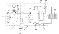
図1は実施の形態1に係るヒートポンプ式給湯暖房システムの概略構成を示すブロック図である。
本実施の形態におけるヒートポンプ式給湯暖房システムは、冷媒配管3で接続された室外機1と室内機2とで構成され、室外機1に設けられた四方弁5によって、冷房運転と暖房・給湯運転の何れかに切り替えることができる。
1 is a block diagram showing a schematic configuration of a heat pump hot water supply / heating system according to
The heat pump hot water supply and heating system in the present embodiment is composed of an
室外機1は、圧縮機4、四方弁5、室外熱交換器6、膨張弁7などを備え、これらの部品と室内機2に設けられた室内熱交換器8とが冷媒配管3で順次に接続されて冷媒回路が構成されている。膨張弁7には、例えば電子膨張弁が用いられている。室外熱交換器6には、室外熱交換器6に流入する冷媒を室外空気と熱交換させる送風機9が設置されている。
The
室内機2は、室内熱交換器8、ヒーター内蔵容器12、三方弁13、貯湯タンク14、水循環ポンプ11などを備え、これら部品が水配管10で順次に接続されて水回路が構成されている。この水回路には、放熱機器15が接続されている。この放熱機器15は、室内に設置され、水流入側が水配管10を介して三方弁13と接続され、水流出側が水配管10を介して水循環ポンプ11と接続されている。三方弁13には、例えば電動三方弁が使用されている。
The
また、水回路には、水流量センサー16、入水温度センサー17及び出湯温度センサー18が設置されている。水流量センサー16は、水循環ポンプ11の水流入側の水配管10に設置され、水循環ポンプ11の運転によって循環する水の流量を検出する。入水温度センサー17は、室内熱交換器8の水流入側の水配管10に設置され、水循環ポンプ11の運転によって室内熱交換器8に流入する水の温度を検出する。出湯温度センサー18は、ヒーター内蔵容器12の水流出側の水配管10に設置され、ヒーター内蔵容器12から流出する水の温度を検出する。なお、入水温度センサー17と出湯温度センサー18には、例えばサーミスタが使用されている。
The water circuit is provided with a water
ここで、冷媒回路の動作について説明する。まず、冷房運転時の冷媒の流れについて説明する。
冷房運転時においては、圧縮機4の運転によって吐出された高温高圧のガス冷媒は、四方弁5を通って室外熱交換器6に流入する。室外熱交換器6に流入した高温高圧のガス冷媒は、室外熱交換器6で送風機9が送風する室外空気、つまり外気と熱交換され、低温高圧の過冷却状態の液冷媒となって膨張弁7に流れる。膨張弁7に流れた低温高圧の液冷媒は、減圧されて低温低圧の気液二相冷媒となり、室外機1から室内機2に流れて室内熱交換器8に流入する。室内熱交換器8に流入した気液二相冷媒は、水循環ポンプ11の運転によって室内熱交換器8に流入する循環水と熱交換され、高温低圧の過熱状態のガス冷媒となる。そして、過熱状態のガス冷媒は、室内機2から室外機1へ流れ、四方弁5を介して圧縮機4に吸入される。
Here, the operation of the refrigerant circuit will be described. First, the refrigerant flow during the cooling operation will be described.
During the cooling operation, the high-temperature and high-pressure gas refrigerant discharged by the operation of the
次に、暖房運転時の冷媒回路の動作について説明する。
暖房運転時においては、圧縮機4の運転によって吐出された高温高圧のガス冷媒は、四方弁5を通って室外機1から室内機2に流れ、室内熱交換器8に流入する。室内熱交換器8に流入した高温高圧のガス冷媒は、水循環ポンプ11の運転によって室内熱交換器8に流入する循環水と熱交換されて放熱し、低温高圧の過冷却状態の液冷媒になる。その後、低温高圧の液冷媒は、室内機2から室外機1へ流れ、膨張弁7によって減圧されて低温低圧の気液二相冷媒となり、室外熱交換器6に流入する。室外熱交換器6に流入した低温低圧の冷媒は、送風機9が送風する室外空気と熱交換され、高温低圧の過熱状態のガス冷媒となる。そして、過熱状態のガス冷媒は、室外熱交換器6から四方弁5を介して圧縮機4に吸入される。
Next, the operation of the refrigerant circuit during the heating operation will be described.
During the heating operation, the high-temperature and high-pressure gas refrigerant discharged by the operation of the
次に、室内機2による水回路の動作について説明する。ここでは、暖房・給湯運転時の水の流れについて説明する。
水循環ポンプ11の運転によって吐出された水は、室内熱交換器8に流入し、室外機1からのを高温高圧のガス冷媒と熱交換されて温水となる。その後、温水は、ヒーター内蔵容器12に流れ、必要に応じて再加熱されて三方弁13に流入し、三方弁13の切り替えに基づいて、貯湯タンク14あるいは放熱機器15の何れかに流れる。ユーザーのリモコン操作によって給湯が選択されていた場合には、温水は、貯湯タンク14内に流入して水と熱交換され、低温水となって水循環ポンプ11により吸引される。暖められた貯湯タンク14内の温水は、給湯用として使用される。また、ユーザーのリモコン操作によって暖房が選択されていた場合には、温水は、放熱機器15内に流入して放熱され、低温水となって水循環ポンプ11により吸引される。放熱機器15で放熱された熱は、輻射暖房用として使用される。
Next, the operation of the water circuit by the
The water discharged by the operation of the
例えば暖房運転中においては、制御装置100は、水流量センサー16により検出された水流量Qと、出湯温度センサー18により検出された出湯温度Wout と、入水温度センサー17により検出された入水温度Winとを基に、現在運転中の加熱能力(以下、「現在能力CAP」という)を算出する。この現在能力CAPは、下記に示す(1)式から求められる。
For example, during the heating operation, the
CAP=Cp×Q×(Wout−Win )・・・(1)
CAP:現在能力
Cp :水の比熱
Q :水流量
Wout :出湯温度
Win :入水温度
CAP = Cp × Q × (Wout−Win) (1)
CAP: Current capacity Cp: Specific heat of water Q: Water flow rate Wout: Hot water temperature Win: Water temperature
また、制御装置100は、例えばリモコン操作により設定された目標加熱能力(以下、「目標能力CAPt」という)と現在能力CAPの比と、現在の運転周波数COMとの2つの変数を含む関数式F(x、y)を用いて、圧縮機4の目標運転周波数COMtを算出する。この目標運転周波数COMtは、下記に示す(2)式から求められる。
COMt=F(COM、CAPt/CAP)・・・(2)
COMt :目標運転周波数
F(x、y):関数式
COM :現在の運転周波数
CAPt :目標能力
CAP :現在能力
In addition, the
COMt = F (COM, CAPt / CAP) (2)
COMt: Target operating frequency F (x, y): Functional expression COM: Current operating frequency CAPt: Target capacity CAP: Current capacity
前述の目標運転周波数COMtの算出は、圧縮機4の制御動作を説明するときに詳述するが、目標能力CAPtと現在能力CAPとの差の絶対値が第1定数αよりも大きいときに行われる。
なお、(2)式に示す関数式は、システムの形態によって異なり、理論式や試験結果から決定する。
The calculation of the target operation frequency COMt will be described in detail when the control operation of the
The function formula shown in formula (2) differs depending on the system configuration and is determined from the theoretical formula and test results.
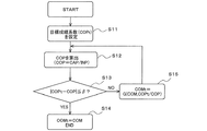
次に、圧縮機4の制御について、図2に示すフローチャートに基づいて説明する。
図2は図1のヒートポンプ式給湯暖房システムにおける圧縮機の制御動作を示すフローチャートである。
制御装置100は、例えば、リモコン操作によって暖房運転が選択されると、室内熱交換器8が凝縮器として、室外熱交換器6が蒸発器として作用するように、四方弁5を切り替える。そして、制御装置100は、圧縮機4の運転を開始して冷媒回路内の冷媒を循環させ、水循環ポンプ11の運転を開始して水回路内の水を循環させる。
Next, control of the
FIG. 2 is a flowchart showing the control operation of the compressor in the heat pump hot water supply and heating system of FIG.
For example, when the heating operation is selected by remote control operation, the
その後、制御装置100は、リモコン操作によって、加熱の目標能力CAPtが設定されると(S1)、水流量センサー16により検出された水流量Qと、出湯温度センサー18により検出された出湯温度Woutと、入水温度センサー17により検出された入水温度Winと、水の比熱Cpとから現在能力CAPを算出する(S2)。
Thereafter, when the heating target capacity CAPt is set by remote control operation (S1), the
そして、制御装置100は、目標能力CAPtと現在能力CAPとの差の絶対値と第1定数αとを比較する(S3)。制御装置100は、絶対値が第1定数αよりも小さいときには、S4へ移行するが、絶対値が第1定数αよりも大きいときには、現在の運転周波数COMと、目標能力CAPtと現在能力CAPの比とによる2つの変数を含む関数式F(x、y)を用いて目標運転周波数COMtを算出する(S5)。
Then, the
制御装置100は、圧縮機4の現在の運転周波数COMが、算出した目標運転周波数COMtとなるように圧縮機4を制御する。制御装置100は、この制御により変化する水流量Q、出湯温度Wout及び入水温度Winと、水の比熱Cpとから再び現在能力CAPを算出する(S2)。そして、制御装置100は、目標能力CAPtと現在能力CAPとの差の絶対値と第1定数αとを比較する(S3)。
The
制御装置100は、絶対値が第1定数αよりも大きいときには、前述した動作を繰り返し行う(S3、S5、S2)。制御装置100は、その動作の繰り返しにより、絶対値が第1定数αよりも小さくなったときには、圧縮機4の運転周波数COMが目標運転周波数COMtに達したと見なして終了する(S4)。つまり、現在能力CAPが目標能力CAPtに達したと見なして、この状態が維持されるようにする。
When the absolute value is larger than the first constant α, the
以上のように実施の形態1においては、水流量Q、出湯温度Wout及び入水温度Winを基に算出した現在能力CAPが、目標能力CAPtに到達するまで圧縮機4の運転周波数COMを変化させ、目標能力CAPtと現在能力CAPとの差の絶対値が第1定数αよりも小さくなったときに、圧縮機4の運転周波数COMが目標運転周波数COMtに達したと見なすようにしている。この制御により、水回路の負荷状態が未知でも正確に現在能力CAPを算出することができる。このため、放熱機器15の負荷が変動する暖房システムでも、必要な目標能力CAPtへの制御ができる。
As described above, in the first embodiment, the operation frequency COM of the
また、室外機の熱交換器が着霜した場合においても、正確な現在能力CAPを算出することができ、このため、目標能力CAPtの維持が可能となり、ユーザーからの能力要求に対応できるようになり、また、規格に対応した試験において有利になる。 Moreover, even when the heat exchanger of the outdoor unit is frosted, the accurate current capacity CAP can be calculated, so that the target capacity CAPt can be maintained and the capacity request from the user can be met. In addition, it is advantageous in a test corresponding to the standard.
なお、実施の形態1では、圧縮機4の周波数制御に適用したが、送風機9の回転数制御と膨張弁7の開度制御にも適用が可能である。この場合、送風機9の目標回転数、及び膨張弁7の目標開度は、制御対象の現在値と、目標能力と現在能力の比とによる2つの変数を含む関数式を用いて演算する。このように適用範囲を広げることで、より精度良く現在能力CAPを目標能力CAPtに到達させることができる。また、同じ能力でもよりCOP(Coefficient Of Performance; 成績係数)を向上させるような制御も可能となる。
In the first embodiment, the present invention is applied to the frequency control of the
実施の形態2.
図3は実施の形態2に係るヒートポンプ式給湯暖房システムにおける圧縮機の制御動作を示すフローチャートである。なお、実施の形態2に係るヒートポンプ式給湯暖房システムは、図1に示す実施の形態1と同様である。
本実施の形態2は、現在COPが目標COPtに到達するまで圧縮機4の運転周波数COMを変化させ、目標COPtと現在COPとの差の絶対値が第2定数βよりも小さくなったときに、圧縮機4の運転周波数COMが目標運転周波数COMtに達したと見なすようにしたものである。
FIG. 3 is a flowchart showing the control operation of the compressor in the heat pump hot water supply and heating system according to the second embodiment. In addition, the heat pump hot water supply and heating system according to
In the second embodiment, the operating frequency COM of the
本実施の形態における制御装置100は、例えば暖房運転に応じて設定された目標COP及び現在COPの比と現在の運転周波数COMとの2つの変数を含む関数式G(x、y)を用いて、圧縮機4の目標運転周波数COMtを算出する。この目標運転周波数COMtは、下記に示す(3)式から求められる。
COMt=G(COM、COPt/COP)・・・(3)
COMt :目標運転周波数
G(x、y):関数式
COM :現在の運転周波数
COPt :目標COP
COP :現在COP
The
COMt = G (COM, COPt / COP) (3)
COMt: target operation frequency G (x, y): function expression COM: current operation frequency COPt: target COP
COP: Current COP
前述の目標運転周波数COMtの算出は、圧縮機4の制御動作を説明するときに詳述するが、目標COPと現在COPとの差の絶対値が第2定数βよりも大きいときに行われる。
なお、(3)式に示す関数式は、システムの形態によって異なり、理論式や試験結果から決定する。
The calculation of the target operation frequency COMt will be described in detail when the control operation of the
Note that the function equation shown in equation (3) varies depending on the system configuration and is determined from the theoretical equation and test results.
また、制御装置100は、圧縮機4への入力電力(入力電圧と入力電流とから算出)と、ヒーター内蔵容器12のヒーターへの入力電力とを合算して入力電力INPを算出することができるので、現在能力CAPと入力電力INPとからCOP(Coefficient Of Performance; 成績係数)を算出する。そのCOPは、次の(4)式から求められる。
COP=CAP/INP・・・(4)
COP:成績係数
CAP:現在能力
INP:入力電力
Further, the
COP = CAP / INP (4)
COP: Coefficient of performance CAP: Current capacity INP: Input power
本実施の形態においては、制御装置100は、例えばリモコン操作によって暖房運転が選択されると、前述したように、室内熱交換器8が凝縮器として、室外熱交換器6が蒸発器として作用するように、四方弁5を切り替える。そして、制御装置100は、圧縮機4の運転を開始して冷媒回路内の冷媒を循環させ、水循環ポンプ11の運転を開始して水回路内の水を循環させる。
In the present embodiment, when the heating operation is selected, for example, by a remote control operation, the
その後、制御装置100は、例えば暖房運転に応じて目標COPを設定し(S11)、水流量センサー16により検出された水流量Qと、出湯温度センサー18により検出された出湯温度Wout と、入水温度センサー17により検出された入水温度Winと、水の比熱Cpとから現在能力CAPを算出する。そして、制御装置100は、圧縮機4への入力電力と、ヒーター内蔵容器12のヒーターへの入力電力とを合算して入力電力INPを算出し、算出した現在能力CAPと入力電力INPとから現在COPを算出する(S12)。
Thereafter, the
制御装置100は、目標COPtと現在COPとの差の絶対値と第2定数βとを比較する(S13)。制御装置100は、絶対値が第2定数βよりも小さいときには、S14へ移行するが、絶対値が第2定数βよりも大きいときには、現在の運転周波数COMと、目標COPtと現在COPの比とによる2つの変数を含む関数式G(x、y)を用いて目標運転周波数COMtを算出する(S15)。
The
制御装置100は、圧縮機4の現在の運転周波数COMが、算出した目標運転周波数COMtとなるように圧縮機4を制御する。制御装置100は、この制御により変化する水流量Q、出湯温度Wout 及び入水温度Winと、水の比熱Cpとから再び現在能力CAPを算出する。また、制御装置100は、入力電力INPを算出し、算出した現在能力CAPと入力電力INPとから再び現在COPを算出する(S12)。そして、制御装置100は、目標COPtと現在COPとの差の絶対値と第2定数βとを比較する(S13)。
The
制御装置100は、絶対値が第2定数βよりも大きいときには、前述した動作を繰り返し行う(S13、S15、S12)。制御装置100は、その動作の繰り返しにより、絶対値が第2定数βよりも小さくなったときには、圧縮機4の運転周波数COMが目標運転周波数COMtに達したと見なして終了する(S14)。つまり、現在COPが目標COPtに達したと見なして、この状態が維持されるようにする。
When the absolute value is larger than the second constant β, the
以上のように実施の形態2においては、現在COPが目標COPtに到達するまで圧縮機4の運転周波数COMを変化させ、目標COPtと現在COPとの差の絶対値が第2定数βよりも小さくなったときに、圧縮機4の運転周波数COMが目標運転周波数COMtに達したと見なすようにしている。この制御により、水回路の負荷状態が未知でも正確に現在COPを算出することができる。このため、放熱機器15の負荷が変動する暖房システムでも、必要な目標COPtへの制御ができる。
As described above, in the second embodiment, the operating frequency COM of the
また、必要な目標COPに応じた制御が可能となるので、省エネルギー効果の高いヒートポンプ式給湯暖房システムを提供できる。 Moreover, since control according to the required target COP is possible, a heat pump hot water supply / heating system with high energy saving effect can be provided.
なお、実施の形態2では、圧縮機4の周波数制御に適用したが、送風機9の回転数制御と膨張弁7の開度制御にも適用が可能である。この場合、送風機9の目標回転数、及び膨張弁7の目標開度は、制御対象の現在値と、目標能力と現在能力の比とによる2つの変数を含む関数式を用いて演算する。このように適用範囲を広げることで、より精度良く現在COPを目標COPに到達させることができる。また、同じCOPでもより能力を向上させるような制御も可能となる。
In the second embodiment, the present invention is applied to the frequency control of the
さらに、上記の手法を応用すれば、目標COPに近づけるだけではなく、COPが最大となる点を探索するように圧縮機4の運転周波数、送風機9の回転数、膨張弁7の開度を最適化することも可能となる。
Furthermore, if the above method is applied, not only the target COP is approached, but also the operating frequency of the
なお、実施の形態1、2では、ヒートポンプ式給湯暖房システムを例にとって説明したが、これに限定されるものではなく、他の任意の設備機器にも利用可能である。例えば、給湯機、冷水機等の設備機器にも適用が可能である。 In the first and second embodiments, the heat pump hot water supply / heating system has been described as an example. However, the present invention is not limited to this, and the present invention can be used for any other equipment. For example, the present invention can be applied to equipment such as a water heater and a chiller.
1 室外機、2 室内機、3 冷媒配管、4 圧縮機、5 四方弁、6 室外熱交換器、7 膨張弁、8 室内熱交換器、9 送風機、10 水配管、11 水循環ポンプ、12 ヒーター内蔵容器、13 三方弁、14 貯湯タンク、15 放熱機器、16 水流量センサー、17 入水温度センサー、18 出湯温度センサー、100 制御装置。
DESCRIPTION OF
Claims (2)
水回路内の水を循環させる水循環ポンプと、
前記水回路内を循環する水を前記冷媒回路内を循環する冷媒と熱変換する熱交換器と、
前記熱交換器に流入する水温を検出する入水温度センサーと、
前記熱交換器から流出する湯温を検出する出湯温度センサーと、
前記水回路内を循環する水の流量を検出する流量センサーと、
前記圧縮機を制御する制御装置とを備え、
前記制御装置は、前記水温、前記湯温及び流量を基に現在の加熱能力を算出し、目標加熱能力と前記加熱能力との差の絶対値と第1定数とを比較し、前記絶対値が第1定数よりも大きいときには、前記圧縮機の運転周波数と、前記目標加熱能力と前記加熱能力の比とに基づいて、前記絶対値が第1定数よりも小さくなる目標運転周波数を算出し、前記圧縮機の運転周波数が前記目標運転周波数となるように制御することを特徴とするヒートポンプ式給湯暖房システム。 A compressor for circulating the refrigerant in the refrigerant circuit;
A water circulation pump for circulating the water in the water circuit;
A heat exchanger for heat-converting water circulating in the water circuit with refrigerant circulating in the refrigerant circuit;
An incoming water temperature sensor for detecting the temperature of water flowing into the heat exchanger;
A hot water temperature sensor for detecting the temperature of hot water flowing out of the heat exchanger;
A flow sensor for detecting a flow rate of water circulating in the water circuit;
A control device for controlling the compressor,
The control device calculates a current heating capacity based on the water temperature, the hot water temperature and the flow rate, compares the absolute value of the difference between the target heating capacity and the heating capacity with a first constant, and the absolute value is When larger than the first constant, based on the operating frequency of the compressor and the ratio of the target heating capacity and the heating capacity, the target operating frequency where the absolute value is smaller than the first constant is calculated, A heat pump hot water supply and heating system, wherein the operation frequency of the compressor is controlled to be the target operation frequency .
水回路内の水を循環させる水循環ポンプと、
前記水回路内を循環する水を前記冷媒回路内を循環する冷媒と熱変換する熱交換器と、 前記熱交換器に流入する水温を検出する入水温度センサーと、
前記熱交換器から流出する湯温を検出する出湯温度センサーと、
前記水回路内を循環する水の流量を検出する流量センサーと、
前記圧縮機を制御する制御装置とを備え、
前記制御装置は、前記水温、前記湯温及び流量を基に算出した加熱能力と入力電力とを基にCOPを算出し、目標COPと前記COPとの差の絶対値と第2定数とを比較し、前記絶対値が第2定数よりも大きいときには、前記圧縮機の運転周波数と、目標COPと前記COPの比とに基づいて、前記絶対値が第2定数よりも小さくなる目標運転周波数を算出し、前記圧縮機の運転周波数が前記目標運転周波数となるように制御することを特徴とするヒートポンプ式給湯暖房システム。 A compressor for circulating the refrigerant in the refrigerant circuit;
A water circulation pump for circulating the water in the water circuit;
A heat exchanger that thermally converts water circulating in the water circuit with a refrigerant circulating in the refrigerant circuit; an incoming water temperature sensor that detects a water temperature flowing into the heat exchanger;
A hot water temperature sensor for detecting the temperature of hot water flowing out of the heat exchanger;
A flow sensor for detecting a flow rate of water circulating in the water circuit;
A control device for controlling the compressor,
The control device calculates a COP based on the heating capacity calculated based on the water temperature, the hot water temperature and the flow rate and the input power, and compares the absolute value of the difference between the target COP and the COP with a second constant. When the absolute value is larger than the second constant, the target operating frequency where the absolute value is smaller than the second constant is calculated based on the operating frequency of the compressor and the ratio of the target COP to the COP. heat Toponpu type hot-water supply heating system, and operating frequency of the compressor and controls so that the target operating frequency.
Priority Applications (1)
| Application Number | Priority Date | Filing Date | Title |
|---|---|---|---|
| JP2013264076A JP6072670B2 (en) | 2013-12-20 | 2013-12-20 | Heat pump hot water supply / heating system |
Applications Claiming Priority (1)
| Application Number | Priority Date | Filing Date | Title |
|---|---|---|---|
| JP2013264076A JP6072670B2 (en) | 2013-12-20 | 2013-12-20 | Heat pump hot water supply / heating system |
Publications (3)
| Publication Number | Publication Date |
|---|---|
| JP2015121336A JP2015121336A (en) | 2015-07-02 |
| JP2015121336A5 JP2015121336A5 (en) | 2015-10-01 |
| JP6072670B2 true JP6072670B2 (en) | 2017-02-01 |
Family
ID=53533097
Family Applications (1)
| Application Number | Title | Priority Date | Filing Date |
|---|---|---|---|
| JP2013264076A Expired - Fee Related JP6072670B2 (en) | 2013-12-20 | 2013-12-20 | Heat pump hot water supply / heating system |
Country Status (1)
| Country | Link |
|---|---|
| JP (1) | JP6072670B2 (en) |
Families Citing this family (3)
| Publication number | Priority date | Publication date | Assignee | Title |
|---|---|---|---|---|
| CN107525267A (en) * | 2017-09-15 | 2017-12-29 | 佛山市澳霆环境设备制造有限公司 | A kind of high-efficient compressor system |
| CN109237751B (en) * | 2018-07-25 | 2021-06-11 | 广东芬尼能源技术有限公司 | Method, device, equipment and medium for quickly achieving unit target capacity |
| CN113834150B (en) * | 2021-09-27 | 2022-09-27 | 广东美的制冷设备有限公司 | Multi-online heat pump system, control method thereof and computer readable storage medium |
Family Cites Families (4)
| Publication number | Priority date | Publication date | Assignee | Title |
|---|---|---|---|---|
| JP3744495B2 (en) * | 2003-01-29 | 2006-02-08 | 松下電器産業株式会社 | Water heater |
| JP4505363B2 (en) * | 2005-03-29 | 2010-07-21 | 東洋熱工業株式会社 | Control method of cold / hot water in air conditioning system |
| JP4711852B2 (en) * | 2006-02-24 | 2011-06-29 | 三菱電機株式会社 | Temperature adjusting device and refrigeration cycle |
| WO2011129248A1 (en) * | 2010-04-15 | 2011-10-20 | 三菱電機株式会社 | Controller for water heater system, program for controlling water heater system, and method for operating water heater system |
-
2013
- 2013-12-20 JP JP2013264076A patent/JP6072670B2/en not_active Expired - Fee Related
Also Published As
| Publication number | Publication date |
|---|---|
| JP2015121336A (en) | 2015-07-02 |
Similar Documents
| Publication | Publication Date | Title |
|---|---|---|
| US9797614B2 (en) | Air conditioning system | |
| JP6320568B2 (en) | Refrigeration cycle equipment | |
| JP5228023B2 (en) | Refrigeration cycle equipment | |
| JP6109205B2 (en) | Refrigeration cycle apparatus and control method of refrigeration cycle apparatus | |
| KR20100123729A (en) | Refrigeration device | |
| JP2014163594A (en) | Flow control device and fluid circuit system | |
| JP6950191B2 (en) | Air conditioner | |
| WO2017120503A1 (en) | Vapor compression system | |
| JP2008121982A (en) | Refrigerating cycle device | |
| JP6072670B2 (en) | Heat pump hot water supply / heating system | |
| US20210025627A1 (en) | Air-conditioning apparatus | |
| JP6133129B2 (en) | Temperature control device | |
| JP5934916B2 (en) | Refrigeration cycle apparatus and hot water generator provided with the same | |
| JP5889347B2 (en) | Refrigeration cycle apparatus and refrigeration cycle control method | |
| KR101533696B1 (en) | Temperature control apparatus using thermoelectric element for cooling performance improvement | |
| JP2016040500A (en) | Composite heat source heat pump device | |
| JP5479625B2 (en) | Refrigeration cycle apparatus and refrigeration cycle control method | |
| JPWO2012114462A1 (en) | Air conditioning and hot water supply system and control method for air conditioning and hot water supply system | |
| JP2016050731A (en) | Heat pump system | |
| JP6389703B2 (en) | Heat pump system | |
| JP2014145522A (en) | Temperature control system | |
| JP2012167889A (en) | Cold/hot water supply apparatus | |
| JP6496346B2 (en) | Temperature control device | |
| JP2004232905A (en) | Refrigerator | |
| JPH08145482A (en) | Multi-chamber split type heater |
Legal Events
| Date | Code | Title | Description |
|---|---|---|---|
| A521 | Written amendment |
Free format text: JAPANESE INTERMEDIATE CODE: A523 Effective date: 20150812 |
|
| A621 | Written request for application examination |
Free format text: JAPANESE INTERMEDIATE CODE: A621 Effective date: 20150812 |
|
| A977 | Report on retrieval |
Free format text: JAPANESE INTERMEDIATE CODE: A971007 Effective date: 20160616 |
|
| A131 | Notification of reasons for refusal |
Free format text: JAPANESE INTERMEDIATE CODE: A131 Effective date: 20160628 |
|
| A521 | Written amendment |
Free format text: JAPANESE INTERMEDIATE CODE: A523 Effective date: 20160818 |
|
| TRDD | Decision of grant or rejection written | ||
| A01 | Written decision to grant a patent or to grant a registration (utility model) |
Free format text: JAPANESE INTERMEDIATE CODE: A01 Effective date: 20161206 |
|
| A61 | First payment of annual fees (during grant procedure) |
Free format text: JAPANESE INTERMEDIATE CODE: A61 Effective date: 20161228 |
|
| R150 | Certificate of patent or registration of utility model |
Ref document number: 6072670 Country of ref document: JP Free format text: JAPANESE INTERMEDIATE CODE: R150 |
|
| R250 | Receipt of annual fees |
Free format text: JAPANESE INTERMEDIATE CODE: R250 |
|
| LAPS | Cancellation because of no payment of annual fees |