JP6072588B2 - Forklift head guard - Google Patents
Forklift head guard Download PDFInfo
- Publication number
- JP6072588B2 JP6072588B2 JP2013073841A JP2013073841A JP6072588B2 JP 6072588 B2 JP6072588 B2 JP 6072588B2 JP 2013073841 A JP2013073841 A JP 2013073841A JP 2013073841 A JP2013073841 A JP 2013073841A JP 6072588 B2 JP6072588 B2 JP 6072588B2
- Authority
- JP
- Japan
- Prior art keywords
- plate portion
- top plate
- plate
- roof
- joined
- Prior art date
- Legal status (The legal status is an assumption and is not a legal conclusion. Google has not performed a legal analysis and makes no representation as to the accuracy of the status listed.)
- Active
Links
Images


Description
本発明は、フォークリフトのヘッドガードに関する。 The present invention relates to a head guard for a forklift.
各種の荷物の運搬、積み降ろしに使用されるフォークリフトにおいて、荷物の高所への積み降ろしの際に、荷崩れ等により、荷物が落下した際に、荷物からオペレータを守るための防護装置としてヘッドガードが装着されている。
ヘッドガードは、フォークリフトの車体前部に車幅方向に間隔を有して配設された左右一対の前側支柱と、車体後部に車幅方向に間隔を有して配設された左右一対の後側支柱と、前側支柱と後側支柱間に架設されたルーフとを有しており、オペレータを落下する荷物から守るために剛性の高い構造にしてある。
特許文献1には、支柱部から一体的に延設された略方形枠状の外フレームと、この外フレームの内側において補強材を格子状に組み合わせてなる内フレームとで構成されたルーフが記載されている。
Forklifts used for transporting and unloading various types of luggage, the head as a protective device to protect the operator from the load when the load falls due to collapse of the load when loading or unloading the load. A guard is attached.
The head guard includes a pair of left and right front struts disposed in the vehicle front portion of the forklift with an interval in the vehicle width direction, and a pair of left and right rear posts disposed in the vehicle rear portion with a space in the vehicle width direction. It has a side strut and a roof erected between the front strut and the rear strut, and has a highly rigid structure to protect the operator from falling luggage.
Patent Document 1 describes a roof composed of a substantially rectangular frame-shaped outer frame integrally extended from a support column, and an inner frame formed by combining reinforcing materials in a lattice shape inside the outer frame. Has been.
しかしながら、上述したルーフは、十分な強度を得るために、中空材や中実材といった様々な材料にて構成されている上、補強材を格子状に組み合わせて溶接するので、材料費や、溶接作業などの接合作業に要する費用が高額となり、ヘッドガードの製造費用を削減できなかった。
本発明は、上記課題に鑑みてなされたものであり、製造費用の削減が可能なヘッドガードを提供することを目的とする。
However, in order to obtain sufficient strength, the above-described roof is composed of various materials such as a hollow material and a solid material, and the reinforcing material is welded in combination in a lattice shape. The cost required for joining work such as work became high, and the manufacturing cost of the head guard could not be reduced.
The present invention has been made in view of the above problems, and an object thereof is to provide a head guard capable of reducing manufacturing costs.
本発明は、板状体の中央に設けられた平面視矩形の天板部と、前記板状体の両側側縁部に前記天板部と隣接して設けられ、前記天板部の上面に対して直角に折り曲げられた左右一対の側板部と、前記板状体の前縁部に前記天板部と隣接して設けられ、前記天板部の上面に対して折り曲げられて前記側板部に接合された前板部と、前記板状体の後縁部に前記天板部と隣接して設けられ、前記天板部の上面に対して直角に折り曲げられて前記側板部に接合された後板部と、を有するルーフを備えたことを特徴とする。
本発明は、板状体でルーフを構成するので、接合箇所が少なくて済む。これにより、溶接作業などの接合作業が少なくて済み、十分な強度を維持しながら、ヘッドガードの製造費用の削減が可能となる。
The present invention is a rectangular top plate portion provided in the center of the plate-like body, provided on both side edges of the plate-like body adjacent to the top plate portion, and on the top surface of the top plate portion. A pair of left and right side plates bent at right angles to the front plate, adjacent to the top plate at the front edge of the plate-like body, and bent to the top surface of the top plate to After the joined front plate portion and the rear edge portion of the plate-like body are provided adjacent to the top plate portion, bent at a right angle with respect to the upper surface of the top plate portion, and joined to the side plate portion And a roof having a plate portion.
In the present invention, since the roof is formed of a plate-like body, the number of joints is small. As a result, the joining work such as the welding work can be reduced, and the manufacturing cost of the head guard can be reduced while maintaining a sufficient strength.
前記ルーフは、前記天板部の前部上面に設けられ、前記左右一対の側板部を相互に接続する第1の補強部と、前記天板部の後部上面に設けられ、前記左右一対の側板部を相互に接続する第2の補強部と、を有することが好ましい。
このようにすれば、ルーフは堅牢なものとなる。
The roof is provided on the upper surface of the front portion of the top plate portion, and is provided on the upper surface of the rear portion of the top plate portion and a first reinforcing portion that connects the pair of left and right side plate portions to each other, and the pair of left and right side plates. It is preferable to have the 2nd reinforcement part which connects a part mutually.
In this way, the roof is robust.
また、前記ルーフは、前記第1の補強部と前記第2の補強部との間に架設した桟部を有することが好ましい。
このようにすれば、ルーフはさらに堅牢なものとなる。
Moreover, it is preferable that the said roof has a crosspiece constructed between the said 1st reinforcement part and the said 2nd reinforcement part.
In this way, the roof becomes more robust.
さらに、前記桟部は、上に凸となる弧状に形成されたことが好ましい。
このようにすれば、桟部の強度が向上する。
Furthermore, it is preferable that the crosspiece is formed in an arc shape that protrudes upward.
In this way, the strength of the crosspiece is improved.
また、本発明は、前記ルーフをフォークリフトの車体に固定するための支柱を有し、前記ルーフは、前記天板部の下面に接合され、前記支柱が嵌る矩形の位置決め穴が設けられた補強板と、前記位置決め穴に沿って設けられ、前記位置決め穴に嵌められた支柱の側面部が接合されるガイド板と、を備えることが好ましい。
このようにすれば、支柱の位置決めが容易で、かつ、接合強度が高いものとなる。
Further, the present invention has a support column for fixing the roof to the body of the forklift, and the roof is joined to the lower surface of the top plate part and provided with a rectangular positioning hole in which the support column is fitted. And a guide plate that is provided along the positioning hole and to which the side surface portion of the column fitted in the positioning hole is joined.
If it does in this way, positioning of a support will be easy and it will become what has high joint strength.
さらに、前記天板部の下面と前記支柱の上端面との間に間隙をあけて支柱を固定することが好ましい。
このようにすれば、溶接作業などの接合作業により、ルーフがひずんでも、支柱の取り付け長さを調整できる。
Furthermore, it is preferable to fix the column with a gap between the lower surface of the top plate portion and the upper end surface of the column.
If it does in this way, even if a roof is distorted by joining operations, such as welding operation, the attachment length of a support | pillar can be adjusted.
以上説明したように本発明は、板状体でルーフを構成するので、接合箇所が少なくて済む。これにより、溶接作業などの接合作業が少なくて済み、ヘッドガードの製造費用の削減が可能となる。 As described above, according to the present invention, since the roof is formed of a plate-like body, the number of joints is small. As a result, the joining work such as the welding work can be reduced, and the manufacturing cost of the head guard can be reduced.
以下、本発明の好適な実施の形態について詳細に説明する。なお、以下に説明する本実施形態は、特許請求の範囲に記載された本発明の内容を不当に限定するものではなく、本実施形態で説明される構成の全てが本発明の解決手段として必須であるとは限らない。 Hereinafter, preferred embodiments of the present invention will be described in detail. The present embodiment described below does not unduly limit the contents of the present invention described in the claims, and all the configurations described in the present embodiment are essential as means for solving the present invention. Not necessarily.
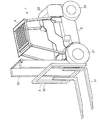
図1は、本発明の実施の形態であるヘッドガードを取り付けたフォークリフトを示す斜視図である。
フォークリフト1は、車体2と、車体2の前部に装着された荷物昇降装置3と、車体2に設けられた運転席を防護するヘッドガード4と、を備えている。車体2は、駆動輪である前輪21、操舵輪である後輪22、後輪22を路面に密着させるカウンタウェイト23を備えるとともに、図示せぬエンジン、前輪駆動用の装置、油圧シリンダ等に油を供給する油圧ポンプ、後輪の操舵装置などの走行及び作業装置を備えている。また、運転席には、図示せぬハンドル、オペレータが着座するシートを備えている。
FIG. 1 is a perspective view showing a forklift attached with a head guard according to an embodiment of the present invention.
The forklift 1 includes a vehicle body 2, a luggage lifting device 3 attached to the front of the vehicle body 2, and a head guard 4 that protects a driver's seat provided in the vehicle body 2. The vehicle body 2 includes a
車体2は、車幅方向の基本断面が矩形状をなし、車両前後方向に延在するとともに、車幅方向に間隔を有する左右一対のサイドフレームと、該左右一対のサイドフレーム間を車幅方向に連結するとともに、前後方向に間隔をあけて配置された複数のクロスメンバとで構成されている。また、左右一対のサイドフレーム間はエンジンカバーで覆われ、エンジンカバーの上面に上述したシートが配設されている。また、車体2は、クロスメンバを介してカウンタウェイト23等が連結されるので、高強度、高剛性に形成されている。
The vehicle body 2 has a rectangular basic cross section in the vehicle width direction, extends in the vehicle front-rear direction, and has a pair of left and right side frames spaced in the vehicle width direction, and the pair of left and right side frames in the vehicle width direction. And a plurality of cross members arranged at intervals in the front-rear direction. The pair of left and right side frames are covered with an engine cover, and the above-described seat is disposed on the upper surface of the engine cover. Further, the vehicle body 2 is formed with high strength and high rigidity because the
荷物昇降装置3は、荷物を載置する側面視がL字状のフォーク(爪)31と、フォーク31が取付けられるバックレスト32と、バックレスト32を上下方向に摺動自在に支持するマスト33と、バックレスト32を上下方向に摺動させるリフトチエーン(図示せず)と、を備えている。また、マスト33の内側に、該マスト33に対し上下方向へ摺動自在に嵌合して、バックレスト32をマスト33の上端より更に上方へ持上げる補助マスト(図示せず)と、マスト33及び補助マストを傾斜させフォーク31の先端を調整するチルトシリンダ(油圧)(図示せず)と、を備えている。これにより、フォーク31の先端を上下に傾斜(調整)させて、フォーク31を荷物の下側へ挿入して、荷物をフォーク31に積載する。補助マストは図示しないリフトシリンダ(油圧)によってマスト33に対し上下に摺動する。
The luggage lifting device 3 includes a fork (claw) 31 having an L-shaped side view for placing a luggage, a
[実施の形態1]
図2〜図5は、本発明の実施の形態1であるヘッドガードを示す図である。また、図6は、図2に示したルーフの構造を説明するための図である。
[Embodiment 1]
2-5 is a figure which shows the head guard which is Embodiment 1 of this invention. FIG. 6 is a view for explaining the structure of the roof shown in FIG.
図2に示すように、本実施の形態1であるヘッドガード4は、ルーフ5と、ルーフ5を支持する4本の支柱6とを備えて構成されている。ルーフ5は、規格化された鋼板(例えば、厚み4.5mmの鋼板)を材料に加工したもので、図6(a)に示すように、平坦かつ一様な板状体50を母材とする。
As shown in FIG. 2, the head guard 4 according to the first embodiment includes a
図6(a)に示すように、板状体50は、天板部51となる領域50A、側板部52となる領域50B、前板部53となる領域50C、後板部54となる領域50Dを有する。
天板部51となる領域50Aは、平面視矩形であって、板状体50の中央に設けられる。また、天板部51となる領域50Aには、長手方向一方側に小さな窓51Aが設けられ、他方側に大きな窓51Bが設けられる。そして、小さな窓51Aが設けられた一方側が前側となり、大きな窓51Bが設けられた他方側が後側となる。なお、小さな窓51Aの前後幅は、大きな荷物が運転席に落下しないように、150mmよりも狭く設定されている。
As shown in FIG. 6A, the plate-
The
側板部52となる領域50Bは、天板部51となる領域50Aの長手方向に沿って板状体50の両側側縁部に設けられ、左右一対をなす。また、側板部52となる領域50Bは、図6(b)に示すように、天板部51となる領域50Aの上面に対して直角に折り曲げられて、側板部52となる。図6(a)に示すように、前板部53となる領域50Cは、天板部51となる領域50Aの短手方向に沿って板状体50の前縁部に設けられる。また、前板部53となる領域50Cは、図6(b)に示すように、側板部52と同一方向に折り曲げられて、前板部53となる。そして、側板部52の前縁と前板部53の側縁とが溶接され、側板部52と前板部53とが接合される。図6(a)に示すように、後板部54となる領域50Dは、天板部51となる領域50Aの短手方向に沿って板状体50の後縁部に設けられる。また、後板部54となる領域は、図6(b)に示すように、側板部52と同一方向に、天板部51となる領域50Aの上面に対して直角に折り曲げられて、後板部54となる。そして、側板部52の後縁と後板部54の側縁とが溶接され、側板部52と後板部54とが接合される。これにより、天板部51となる領域50Aが確定する。この様に一つの材料の板金曲げ溶接構成にてルーフ5を構成する事にて、十分な強度を維持しながら、材料費、溶接費の低減が可能となる。
The
また、図2に示すように、ルーフ5は、第1の補強部55と第2の補強部56とを備えている。第1の補強部55は、左右一対の側板部52を相互に接続するもので、図6(C)に示すように、天板部51の小さな窓51Aと大きな窓51Bの境界となる前部上面に設けられている。図5に示すように、第1の補強部55は、細長い矩形の鋼板を溝型(コの字)に折り曲げたもので、両方の開口縁部が天板部51の上面に接合されている。よって、コの字の補強部55と天板部51により、中空パイプと同様の形状の部材を形成している。第2の補強部56は、第1の補強部55と同様、左右一対の側板部52を相互に接続するもので、天板部51の後部上面に設けられている。第2の補強部56は、細長い矩形の鋼板を長手方向に沿って直角に折り曲げ、L字にしたもので、一辺をなす端部が天板部51の上面に対して直角に接合され、他辺をなす端部が後板部54に対して直角に接合されている。よって、L字の補強部56と天板部51と後板部54によって、中空パイプと同様の形状の部材を形成している。第1の補強部55と第2の補強部56は、上述した板状体50と同じ厚みの規格化された鋼板を用いることが好ましい。これにより、材料が共通化され、材料の発注費用、在庫費用の削減が可能になる。
As shown in FIG. 2, the
また、図2〜図5に示すように、第1の補強部55と第2の補強部56との間には桟部57が架設されている。桟部57は、荷崩れした荷物が運転席に落下するのを防止するためのもので、オペレータの安全を確保すべく、定められた間隔で天板部51に設けた大きな窓51Bを複数に区切っている。定められた間隔は、150mmで、150mmを超える大きさの荷物は、桟部57で遮られる。図5に示すように、桟部57は、厚みが9mmで、上に凸となる弧状に形成した板状の部材で構成されている。そして、桟部57は、天板部151の上面に対して直角に配設されている。桟部57は、例えば、レーザーを用いて規格化された厚み9mmの鋼板から切り出される。
As shown in FIGS. 2 to 5, a
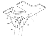
図7は、ルーフとルーフに接合した支柱とを示す図であり、図8は、図7に示したA部拡大図である。また、図9は、支柱の取り付け長さの調整を説明する図である。
また、図7に示すように、ルーフ5は、下面に補強板58を備えている。補強板58は、天板部51を補強するとともに支柱6を位置決めするためのもので、天板部51の前縁下面と後縁下面とに接合されている。補強板58は、平坦かつ一様な厚みを有する細長い板状の部材であって、上述した板状体50と同じ厚みの規格化された鋼板で作成されている。また、補強板58は、図8に示すように、端部に位置決め穴581が設けられている。位置決め穴581は、支柱6を位置決めするためのもので、前後方向に細長い矩形であって、支柱6が嵌る大きさに形成されている。
FIG. 7 is a view showing a roof and a support post joined to the roof, and FIG. 8 is an enlarged view of a portion A shown in FIG. Moreover, FIG. 9 is a figure explaining adjustment of the attachment length of a support | pillar.
Further, as shown in FIG. 7, the
また、図8に示すように、ルーフ5は、補強板58の下面にガイド板59A,59Bを備えている。ガイド板59A,59Bは、支柱6の側面を支持するためのもので、位置決め穴581の外側二辺に沿って設けられている。ガイド板59A,59Bは、略台形形状に形成された平坦かつ一様な厚みを有する板状の部材であって、上述した板状体50と同じ厚みの規格化された鋼板で作成されている。そして、ガイド板59A,59Bは、補強板58に溶接され、固定されている。
Further, as shown in FIG. 8, the
支柱6は、ルーフ5を支持するためのもので、矩形断面を有する角筒で構成されている。角筒は、例えば、60mm×40mmの厚み2mmの規格化された角パイプで構成されている。
The
また、支柱6は、位置決め穴581に嵌ることにより位置決めされ、図9に示すように、その嵌り程度により支柱6の長さが調整される。すなわち、少なくとも一つの支柱6は、天板部51の下面と支柱6の上端面との間に間隙ΔXをあけて取り付けられ、補強板58の厚みの範囲で支柱6の長さが調整される。支柱6は、まず車体側と固定されるが、これによりルーフ5と取り付けられる支柱6の上端面において、複数の支柱6間で長さや角度に差が生じたり、加工誤差が生じることがある。これにより、ルーフ5の溶接ひずみや加工誤差は吸収される。したがって、溶接時のパイプ位置調整が容易で溶接ひずみも発生しにくい。上述した例では、支柱6の長さが最大4.5mm(補強板の厚み)の範囲で調整可能であり、通常の製造において生じる溶接ひずみや加工誤差は吸収される。そして、支柱6は、ガイド板59A,59Bに溶接され、ルーフ5に対して固定される。
Moreover, the support |
上述した本実施の形態1であるヘッドガード4は、板状体50でルーフ5を構成するので、接合箇所が少なくて済む。また、ルーフ5を構成する部材の数を減らすことができる。したがって、溶接作業などの接合作業が少なくて済み、接合作業に要するコストを削減できる。これにより、本実施の形態1であるヘッドガード4の製造費用の削減が可能となる。
In the head guard 4 according to the first embodiment described above, the
また、ルーフ5は、天板部51の前部上面に設けられ、左右一対の側板部52を相互に接続する第1の補強部56と、天板部51の後部上面に設けられ、左右一対の側板部52を相互に接続する第2の補強部56とを有するので、板状部材によって、強度の高いパイプ状の部材を形成することができるため、ルーフ5の強度を確保することができる。
The
また、ルーフ5は、天板部51に小さな窓51Aと大きな窓51Bとを有するので、オペレータは、小さな窓51Aと大きな窓51Bとを通して荷物昇降装置3によって持ち上がられた荷物を視認できる。また、第1の補強部55と第2の補強部56との間に架設した桟部57が予め定めた間隔で大きな窓51Bを複数に区切るので、荷物が荷崩れしても予め定めた間隔を超える大きさの荷物は桟部57に遮られる。これにより、オペレータの安全が確保される。また、桟部は、上に凸となる弧状に形成されたので、強度が向上する。
Further, since the
また、ルーフ5は、天板部51の下面に接合され、支柱6が嵌る矩形の位置決め穴581が設けられた補強板58と、位置決め穴581に嵌められた支柱6の側面が接合されるガイド板59A,59Bとを備えているので、支柱6の位置決めが容易で、かつ、接合強度が高いものとなる。また、支柱6は、位置決め穴581への嵌り程度により取り付け長さを調整できるので、通常の製造において生じる溶接ひずみや加工誤差を吸収することができる。
The
[実施の形態2]
図10〜図13は、本発明の実施の形態2であるヘッドガードを示す図である。また、図14は、図10に示したルーフの制作手順を説明するための図である。
[Embodiment 2]
10-13 is a figure which shows the head guard which is Embodiment 2 of this invention. FIG. 14 is a diagram for explaining a procedure for producing the roof shown in FIG.
図10に示すように、本実施の形態2であるヘッドガード104は、ルーフ105と、ルーフ105を支持する4本の支柱106とを備えて構成されている。ルーフ105は、規格化された鋼板(例えば、厚み4.5mmの鋼板)を材料に加工したもので、図14に示すように、平坦かつ一様な板状体150を母材とする。
As shown in FIG. 10, the
図14(a)に示すように、板状体150は、天板部151となる領域150A、側板部152となる領域150B、前板部153となる領域150C、後板部154となる領域150Dを有する。
天板部151となる領域150Aは、平面視矩形であって、板状体150の中央に設けられる。また、天板部151となる領域150Aには、長手方向一方側に大きな窓151Aが設けられ、他方側に小さな窓151Bが三つ並んで設けられる。そして、大きな窓151Aが設けられた一方側が前側となり、小さな窓151Bが三つ並んで設けられた他方側が後側となる。なお、小さな窓151Bの左右幅は、大きな荷物が運転席に落下しないように、150mmよりも狭く設定されている。
As shown in FIG. 14A, the plate-
The
側板部152となる領域150Bは、天板部151となる領域150Aの長手方向に沿って板状体150の両側側縁部に設けられ、左右一対をなす。また、側板部152となる領域は、図14(b)に示すように、天板部151となる領域150Aの上面に対して直角に折り曲げられて、側板部152となる。図14(a)に示すように、前板部153となる領域150Cは、天板部151となる領域150Aの短手方向に沿って板状体150の前縁部に設けられる。また、前板部153となる領域150Cは、図14(b)に示すように、側板部152と同一方向に折り曲げられて、前板部153となる。そして、側板部152の前縁と前板部153の側縁とが溶接され、側板部152と前板部153とが接合される。図14(a)に示すように、後板部154となる領域150Dは、天板部151となる領域150Aの短手方向に沿って板状体150の後縁部に設けられる。また、後板部154となる領域150Dは、図14(b)に示すように、側板部152と同一方向に、天板部151となる領域150Aの上面に対して直角に折り曲げられて、後板部154となる。そして、側板部152の後縁と後板部154の側縁とが溶接され、側板部152と後板部154とが接合される。これにより、天板部151となる領域150Aが確定する。この様に一つの材料の板金曲げ溶接構成にてルーフ5を構成する事にて、十分な強度を維持しながら、材料費、溶接費の低減が可能となる。
The
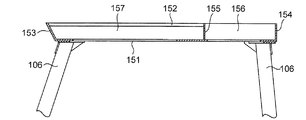
また、図10に示すように、ルーフ105は、第1の補強部155を備えている。第1の補強部155は、左右一対の側板部152を相互に接続するもので、天板部151の大きな窓151Aと三つ並んだ小さな窓151Bの境界となる領域に設けられている。図12に示すように、第1の補強部155は、板状体150と同じ厚みで側板部152と同じ高さの板状の部材であって、天板部151の上面に対して直角に配設され、下面は、天板部151の上面に接合されている。
Further, as shown in FIG. 10, the
また、ルーフ105は、第1の桟部156を備えている。第1の桟部156は、後板部154と第1の補強部155とを相互に接続するもので、小さな窓151Bと小さな窓151Bとの境界となる領域に設けられている。図11に示すように、第1の桟部156は、板状体150と同じ厚みで後板部154と同じ高さの板状の部材であって、天板部151の上面に対して直角に配設され、下面は、天板部151の上面に接合されている。
Further, the
図10〜図13に示すように、前板部153と第1の補強部155との間には第2の桟部157が架設されている。第2の桟部157は、荷崩れした荷物が運転席に落下するのを防止するためのもので、オペレータの安全を確保すべく、定められた間隔で天板部151に設けた大きな窓151Aを複数に区切っている。定められた間隔は、150mmで、150mmを超える大きさの荷物は、第2の桟部157で遮られる。第2の桟部157は板状体150と同じ厚みの板状の部材で構成されている。そして、第2の桟部157は、天板部151の上面に対して直角に配設されている。
As shown in FIGS. 10 to 13, a
図15は、ルーフとルーフに接合した支柱とを示す図であり、図16は、図15に示したB部拡大図である。また、図17は、支柱の取り付け長さの調整を説明する図である。
また、図15に示すように、ルーフ105は、下面に補強板158を備えている。補強板158は、天板部151を補強するとともに支柱106を位置決めするためのもので、天板部151の前縁下面と後縁下面とに接合されている。補強板158は、平坦かつ一様な厚みを有する細長い板状の部材であって、上述した板状体150と同じ厚みの規格化された鋼板で作成されている。また、補強板158は、図16に示すように、端部に位置決め穴1581が設けられている。位置決め穴1581は、支柱106を位置決めするためのもので、前後方向に細長い矩形であって、支柱106が嵌る大きさに形成されている。
FIG. 15 is a view showing the roof and the struts joined to the roof, and FIG. 16 is an enlarged view of a portion B shown in FIG. Moreover, FIG. 17 is a figure explaining adjustment of the attachment length of a support | pillar.
As shown in FIG. 15, the
また、図16に示すように、ルーフ105は、補強板158の下面にガイド板159A,159Bを備えている。ガイド板159A,159Bは、支柱6の側面を支持するためのもので、位置決め穴1581の外側二辺に沿って設けられている。ガイド板159A,159Bは、略台形状に形成された平坦かつ一様な厚みを有する板状の部材であって、上述した板状体150と同じ厚みの規格化された鋼板で作成されている。そして、ガイド板159A,159Bは、補強板158に溶接され、固定されている。
As shown in FIG. 16, the
支柱106は、ルーフ105を支持するためのもので、矩形断面を有する角筒で構成されている。角筒は、例えば、60mm×40mmの厚み2mmの規格化された角パイプで構成されている。
The
また、支柱106は、位置決め穴1581に嵌ることにより位置決めされ、図17に示すように、その嵌り程度により支柱106の長さが調整される。すなわち、少なくとも一つの支柱106は、天板部151の下面と上端面との間に間隙ΔXをあけて取り付けられ、補強板58の厚みの範囲で支柱106の長さが調整される。これにより、ルーフ105の溶接ひずみや加工誤差は吸収される。上述した例では、支柱106の長さが最大4.5mm(補強板の厚み)の範囲で調整可能であり、通常の製造において生じる溶接ひずみや加工誤差は吸収される。そして、支柱106は、ガイド板159A,159Bに溶接され、ルーフ105に対して固定される。
Moreover, the support |
上述した本実施の形態2であるヘッドガード104は、平坦かつ一様な厚みを有する板状体150でルーフ105を構成するので、接合箇所が少なくて済む。したがって、溶接作業などの接合作業が少なくて済み、接合作業に要するコストを削減できる。これにより、本実施の形態2であるヘッドガード104の製造費用の削減が可能となる。
In the
また、ヘッドガード104のルーフ105を同じ厚みの規格化された鋼板で製造できるので、材料の発注費用、在庫費用の削減が可能となる。
Further, since the
また、ルーフ105は、天板部151の中程上面に設けられ、左右一対の側板部52を相互に接続する補強部155と、天板部151の後部上面に設けられ、後板部154と補強部155とを相互に接続する第1の桟部156とを有するので、ルーフ105は堅牢なものとなる。
The
また、ルーフ105は、天板部51に大きな窓151Aを有するので、オペレータは、大きな窓151Aを通して荷物昇降装置3によって持ち上げられた荷物を視認できる。また、前板部153と第1の補強部155との間に架設した第2の桟部157が予め定めた間隔で大きな窓151Aを複数に区切るので、荷物が荷崩れしても予め定めた間隔を超える大きさの荷物は桟部157に遮られる。これにより、オペレータの安全が確保される。
Further, since the
また、ルーフ105は、天板部151の下面に接合され、支柱106が嵌る矩形の位置決め穴1581が設けられた補強板158と、位置決め穴1581に嵌められた支柱106の側面が接合されるガイド板159A,159Bを備えているので、支柱106の位置決めが容易で、かつ、接合強度が高いものとなる。また、支柱106は、位置決め穴1581への嵌り程度により取り付け長さを調整できるので、通常の製造において生じる溶接ひずみや加工誤差を吸収することができる。
Further, the
本発明に係るフォークリフトのヘッドガードは、溶接作業が少なくて済み、製造費用の削減が可能となるので、フォークリフトのヘッドガードに好適である。 The head guard of a forklift according to the present invention is suitable for a head guard of a forklift because it requires less welding work and can reduce manufacturing costs.
1 フォークリフト
2 車体
4 ヘッドガード
5 ルーフ
50 板状体
50A 天板部となる領域
50B 側板部となる領域
50C 前板部となる領域
50D 後板部となる領域
51 天板部
51A 小さな窓
51B 大きな窓
52 側板部
53 前板部
54 後板部
55 第1の補強部
56 第2の補強部
57 桟部
58 補強板
581 位置決め穴
59A,59B ガイド板
6 支柱
104 ヘッドガード
105 ルーフ
106 支柱
150 板状体
150A 天板部となる領域
150B 側板部となる領域
150C 前板部となる領域
150D 後板部となる領域
151 天板部
151A 大きな窓
151B 小さな窓
152 側板部
153 前板部
154 後板部
155 補強部
156 第1の桟部
157 第2の桟部
158 補強板
1581 位置決め穴
159A,159B ガイド板
DESCRIPTION OF SYMBOLS 1 Forklift 2 Car body 4
Claims (9)
前記板状体の両側側縁部に前記天板部と隣接して設けられ、前記天板部の上面に対して直角に折り曲げられた左右一対の側板部と、
前記板状体の前縁部に前記天板部と隣接して設けられ、前記天板部の上面に対して折り曲げられて前記側板部に接合された前板部と、
前記板状体の後縁部に前記天板部と隣接して設けられ、前記天板部の上面に対して直角に折り曲げられて前記側板部に接合された後板部と、
を有するルーフを備え、
前記ルーフは、
前記天板部の前部上面に設けられ、前記天板部と接合されることによってパイプ形状をなし、前記左右一対の側板部を相互に接続する第1の補強部と、
前記天板部の後部上面に設けられ、前記天板部と接合されることによってパイプ形状をなし、前記左右一対の側板部を相互に接続する第2の補強部と、
を有することを特徴とするフォークリフトのヘッドガード。 A rectangular top plate provided in the center of the plate-like body;
A pair of left and right side plates provided on both side edges of the plate-like body adjacent to the top plate, and bent at right angles to the top surface of the top plate,
A front plate portion provided adjacent to the top plate portion at the front edge portion of the plate-like body, bent to the upper surface of the top plate portion, and joined to the side plate portion;
A rear plate portion provided adjacent to the top plate portion at a rear edge portion of the plate-like body, bent at a right angle with respect to an upper surface of the top plate portion, and joined to the side plate portion;
Equipped with a roof with,
The roof is
A first reinforcing portion that is provided on the upper surface of the front portion of the top plate portion, forms a pipe shape by being joined to the top plate portion, and connects the pair of left and right side plate portions to each other;
A second reinforcing portion provided on the upper surface of the rear portion of the top plate portion, formed into a pipe shape by being joined to the top plate portion, and connecting the pair of left and right side plate portions to each other;
Head guard forklift and having a.
前記第1の補強部と前記第2の補強部との間に架設した桟部を有することを特徴とする請求項1〜3のいずれか一つに記載のフォークリフトのヘッドガード。 The roof is
The head guard for a forklift according to any one of claims 1 to 3, further comprising a crosspiece provided between the first reinforcing portion and the second reinforcing portion.
上に凸となる弧状に形成されたことを特徴とする請求項4に記載のフォークリフトのヘッドガード。 The crosspiece is
The forklift head guard according to claim 4 , wherein the head guard is formed in an arc shape protruding upward.
前記ルーフは、
前記天板部の下面に接合され、前記支柱が嵌る矩形の位置決め穴が設けられた補強板と、
前記位置決め穴に沿って設けられ、前記位置決め穴に嵌められた支柱の側面部が接合されるガイド板と、
を備えたことを特徴とする請求項1〜5のいずれか一つに記載のフォークリフトのヘッドガード。 It has a support for fixing the roof to the body of the forklift,
The roof is
A reinforcing plate which is bonded to the lower surface of the top plate portion and provided with a rectangular positioning hole into which the support column is fitted;
A guide plate that is provided along the positioning hole and to which a side surface portion of a column fitted in the positioning hole is joined;
The forklift head guard according to any one of claims 1 to 5 , further comprising:
前記板状体の両側側縁部に前記天板部と隣接して設けられ、前記天板部の上面に対して直角に折り曲げられた左右一対の側板部と、A pair of left and right side plates provided on both side edges of the plate-like body adjacent to the top plate, and bent at right angles to the top surface of the top plate,
前記板状体の前縁部に前記天板部と隣接して設けられ、前記天板部の上面に対して折り曲げられて前記側板部に接合された前板部と、A front plate portion provided adjacent to the top plate portion at the front edge portion of the plate-like body, bent to the upper surface of the top plate portion, and joined to the side plate portion;
前記板状体の後縁部に前記天板部と隣接して設けられ、前記天板部の上面に対して直角に折り曲げられて前記側板部に接合された後板部と、A rear plate portion provided adjacent to the top plate portion at a rear edge portion of the plate-like body, bent at a right angle with respect to an upper surface of the top plate portion, and joined to the side plate portion;
を有するルーフを備え、A roof having
前記ルーフをフォークリフトの車体に固定するための支柱を有し、It has a support for fixing the roof to the body of the forklift,
前記ルーフは、The roof is
前記天板部の下面に接合され、前記支柱が嵌る矩形の位置決め穴が設けられた補強板と、A reinforcing plate which is bonded to the lower surface of the top plate portion and provided with a rectangular positioning hole into which the support column is fitted;
前記位置決め穴に沿って設けられ、前記位置決め穴に嵌められた支柱の側面部が接合されるガイド板と、A guide plate that is provided along the positioning hole and to which a side surface portion of a column fitted in the positioning hole is joined;
を備えたことを特徴とするフォークリフトのヘッドガード。A forklift head guard characterized by comprising
Priority Applications (1)
| Application Number | Priority Date | Filing Date | Title |
|---|---|---|---|
| JP2013073841A JP6072588B2 (en) | 2013-03-29 | 2013-03-29 | Forklift head guard |
Applications Claiming Priority (1)
| Application Number | Priority Date | Filing Date | Title |
|---|---|---|---|
| JP2013073841A JP6072588B2 (en) | 2013-03-29 | 2013-03-29 | Forklift head guard |
Publications (3)
| Publication Number | Publication Date |
|---|---|
| JP2014198612A JP2014198612A (en) | 2014-10-23 |
| JP2014198612A5 JP2014198612A5 (en) | 2015-04-02 |
| JP6072588B2 true JP6072588B2 (en) | 2017-02-01 |
Family
ID=52355798
Family Applications (1)
| Application Number | Title | Priority Date | Filing Date |
|---|---|---|---|
| JP2013073841A Active JP6072588B2 (en) | 2013-03-29 | 2013-03-29 | Forklift head guard |
Country Status (1)
| Country | Link |
|---|---|
| JP (1) | JP6072588B2 (en) |
Families Citing this family (1)
| Publication number | Priority date | Publication date | Assignee | Title |
|---|---|---|---|---|
| KR102414524B1 (en) * | 2020-12-04 | 2022-06-29 | 두산산업차량 주식회사 | Cabin protection structure |
Family Cites Families (4)
| Publication number | Priority date | Publication date | Assignee | Title |
|---|---|---|---|---|
| US4411464A (en) * | 1981-08-03 | 1983-10-25 | Clark Equipment Company | Operator protective posts |
| JPS5864583U (en) * | 1981-10-26 | 1983-04-30 | 三菱重工業株式会社 | forklift head guard |
| JPH0517334Y2 (en) * | 1986-04-30 | 1993-05-10 | ||
| JP2607281Y2 (en) * | 1993-07-12 | 2001-05-28 | ティー・シー・エム株式会社 | Head guard device for cargo handling vehicle |
-
2013
- 2013-03-29 JP JP2013073841A patent/JP6072588B2/en active Active
Also Published As
| Publication number | Publication date |
|---|---|
| JP2014198612A (en) | 2014-10-23 |
Similar Documents
| Publication | Publication Date | Title |
|---|---|---|
| JP5088268B2 (en) | Cab and mobile construction machine equipped with the same | |
| JP6072588B2 (en) | Forklift head guard | |
| JP6834969B2 (en) | Boom for work machinery | |
| RU2660334C1 (en) | Vehicle bottom structure | |
| WO2014083659A1 (en) | Forklift head-guard structure | |
| WO2016016935A1 (en) | Head guard for forklift | |
| CN104925705A (en) | Portal frame assembly used for forklift and forklift with same | |
| JP6607622B1 (en) | Vehicle with head guard | |
| KR20140005809U (en) | A folklift | |
| JP6424585B2 (en) | Tractor | |
| JP2013193800A (en) | Fork shift device | |
| EP2295366B1 (en) | Forklift mast | |
| JP5707221B2 (en) | Reach forklift | |
| JP6632332B2 (en) | Forklift cabin | |
| KR101942213B1 (en) | Mounting structure of new boom | |
| KR101975697B1 (en) | Mounting structure of new boom | |
| JP2021017297A (en) | Boom support structure | |
| JP6331836B2 (en) | Construction machinery | |
| JP7212569B2 (en) | Frame material manufacturing method and vehicle body frame | |
| JP2006088920A (en) | Working machine | |
| KR101716413B1 (en) | Additional leg unit for fork lifting car | |
| JP2021195221A (en) | Load fall prevention device and fork lift equipped with the same | |
| EP3178775B1 (en) | Mast segment for a lift-truck and a lift-truck comprising a mast segment | |
| JP2013124139A (en) | Forklift | |
| JP6455130B2 (en) | Crane vehicle outrigger reinforcement structure |
Legal Events
| Date | Code | Title | Description |
|---|---|---|---|
| A521 | Written amendment |
Free format text: JAPANESE INTERMEDIATE CODE: A523 Effective date: 20150210 |
|
| A621 | Written request for application examination |
Free format text: JAPANESE INTERMEDIATE CODE: A621 Effective date: 20160215 |
|
| A977 | Report on retrieval |
Free format text: JAPANESE INTERMEDIATE CODE: A971007 Effective date: 20161214 |
|
| TRDD | Decision of grant or rejection written | ||
| A01 | Written decision to grant a patent or to grant a registration (utility model) |
Free format text: JAPANESE INTERMEDIATE CODE: A01 Effective date: 20161222 |
|
| A61 | First payment of annual fees (during grant procedure) |
Free format text: JAPANESE INTERMEDIATE CODE: A61 Effective date: 20161228 |
|
| R150 | Certificate of patent or registration of utility model |
Ref document number: 6072588 Country of ref document: JP Free format text: JAPANESE INTERMEDIATE CODE: R150 |
|
| S533 | Written request for registration of change of name |
Free format text: JAPANESE INTERMEDIATE CODE: R313533 |
|
| R350 | Written notification of registration of transfer |
Free format text: JAPANESE INTERMEDIATE CODE: R350 |