JP6066949B2 - Imaging apparatus, control method therefor, and program - Google Patents
Imaging apparatus, control method therefor, and program Download PDFInfo
- Publication number
- JP6066949B2 JP6066949B2 JP2014051585A JP2014051585A JP6066949B2 JP 6066949 B2 JP6066949 B2 JP 6066949B2 JP 2014051585 A JP2014051585 A JP 2014051585A JP 2014051585 A JP2014051585 A JP 2014051585A JP 6066949 B2 JP6066949 B2 JP 6066949B2
- Authority
- JP
- Japan
- Prior art keywords
- image
- acquisition
- imaging
- unit
- pixel group
- Prior art date
- Legal status (The legal status is an assumption and is not a legal conclusion. Google has not performed a legal analysis and makes no representation as to the accuracy of the status listed.)
- Active
Links
Images


Description
本発明は、撮像装置において、撮像素子の出力に基づき初期露出条件を決定して撮像画像を表示させる技術に関する。 The present invention relates to a technique for determining an initial exposure condition based on an output of an image sensor and displaying a captured image in an imaging apparatus.
一般に、CCDやCMOSセンサといった固体撮像素子を有する撮像装置において、撮像画像を撮像素子により取り込み、ライブビュー画面に表示するまでには、露出を適正にしたり補正をしたり等の処理を挟むためにタイムラグが生じる。例えば、撮像電源を入れてから撮像画像がライブビュー表示される際には、そのタイムラグが顕著に感じられる。 In general, in an imaging apparatus having a solid-state imaging device such as a CCD or CMOS sensor, in order to interpose processing such as appropriate exposure and correction until the captured image is captured by the imaging device and displayed on the live view screen. A time lag occurs. For example, when the captured image is displayed in live view after the imaging power is turned on, the time lag is noticeable.
そこで、電源を入れてから撮像装置による映像信号を表示画面に出力するまでの時間を短縮するために、起動時間の高速化の処理が検討されている。特許文献1においては、外部測光センサ及び撮像センサを並行して使用することで、短時間で正確な測光を行う撮像装置が開示されている。 Therefore, in order to shorten the time from when the power is turned on to when the video signal from the imaging device is output to the display screen, processing for increasing the startup time is being studied. Patent Document 1 discloses an imaging apparatus that performs accurate photometry in a short time by using an external photometric sensor and an imaging sensor in parallel.
しかしながら、特許文献1に開示された従来技術では、撮像センサに加え外部測光センサも併用するため、構成が複雑化し、撮像装置全体のコストアップにつながるだけでなく、消費電力の点でも不利であるといった問題があった。 However, the conventional technique disclosed in Patent Document 1 uses an external photometric sensor in addition to the imaging sensor, which complicates the configuration and leads to an increase in the cost of the entire imaging apparatus, and is also disadvantageous in terms of power consumption. There was a problem.
本発明は上記従来技術の問題を解決するためになされたものであり、その目的は、コストアップを回避しつつ、適正露出での画像表示開始までの時間を短縮することにある。 The present invention has been made to solve the above-described problems of the prior art, and an object of the present invention is to shorten the time until the start of image display with appropriate exposure while avoiding an increase in cost.
上記目的を達成するために本発明は、光学像に応じた信号を出力する複数の画素を有する撮像素子と、前記撮像素子の前記複数の画素のうち第1の画素群から読み出される信号から第1の画像を取得する第1の取得手段と、前記撮像素子の前記複数の画素のうち前記第1の画素群と重複しない第2の画素群から読み出される信号から第2の画像を取得する第2の取得手段と、前記第1の取得手段及び前記第2の取得手段のそれぞれによる画像の取得を制御する制御手段と、を有し、前記制御手段は、撮像画像を表示部に表示させていない状態で、第1のフレームレートで且つ第1の露出条件にて、前記第1の取得手段に前記第1の画像を取得させることと、前記第1のフレームレートよりも高速の第2のフレームレートで且つ前記第1の露出条件よりも露光時間が短い第2の露出条件にて、前記第2の取得手段に前記第2の画像を取得させることとを、時間的に並行して行わせると共に、前記第1の取得手段により取得された前記第1の画像から求められる輝度情報と、前記第2の取得手段により取得された前記第2の画像から求められる輝度情報とに基づいて、前記表示部に撮像画像を表示させる際の初期露出条件を決定することを特徴とする。 In order to achieve the above object, the present invention provides an image sensor having a plurality of pixels that output a signal corresponding to an optical image, and a signal read from a first pixel group among the plurality of pixels of the image sensor. A first acquisition unit that acquires one image, and a second image acquired from a signal read from a second pixel group that does not overlap with the first pixel group among the plurality of pixels of the image sensor. 2 acquisition means, and control means for controlling image acquisition by each of the first acquisition means and the second acquisition means, and the control means displays the captured image on the display unit. In the absence of the first image at the first frame rate and the first exposure condition, the first acquisition means acquiring the first image, and a second speed higher than the first frame rate. The first exposure at a frame rate And causing the second acquisition unit to acquire the second image under a second exposure condition that has an exposure time shorter than that of the first acquisition unit. Based on the luminance information obtained from the first image obtained by the above and the luminance information obtained from the second image obtained by the second obtaining means, the captured image is displayed on the display unit. The initial exposure condition is determined.
なお、請求項12記載のプログラムを格納したコンピュータで読み取り可能な記憶媒体は、本発明を構成する。 A computer-readable storage medium storing the program according to claim 12 constitutes the present invention.
本発明によれば、コストアップを回避しつつ、適正露出での画像表示開始までの時間を短縮することができる。 According to the present invention, it is possible to shorten the time until the start of image display with appropriate exposure while avoiding an increase in cost.
以下、本発明の実施の形態を図面を参照して説明する。 Hereinafter, embodiments of the present invention will be described with reference to the drawings.
(第1の実施の形態)
図1は、本発明の第1の実施の形態に係る撮像装置の構成を示すブロック図である。
(First embodiment)
FIG. 1 is a block diagram showing the configuration of the imaging apparatus according to the first embodiment of the present invention.
この撮像装置は一例としてデジタルカメラ100であるとするが、ビデオカメラでもよく、静止画または動画撮影の機能を有する装置に本発明が適用される。
The image pickup apparatus is assumed to be the
図1に示すデジタルカメラ100において、撮影レンズ103はズームレンズ、フォーカスレンズを含むレンズ群である。シャッタ101は絞り機能を備えるシャッタである。撮像部22は光学像を電気信号に変換するCCDやCMOS素子等で構成される撮像素子である。後述する複数の画素201(図2(a))を有すると共に、A/D変換処理機能を備えている。撮像部22はAF評価値検出部23を備える。AF評価値検出部23は、デジタル画像信号から得られるコントラスト情報などから、オートフォーカス制御を行う際に用いられるAF評価値を算出し、得られたAF評価値をシステム制御部50に出力する。バリア105は、撮影レンズ103を覆うことにより、撮影レンズ103、シャッタ101及び撮像部22を含む撮像系の汚れや破損を防止する。
In the
画像処理部24は、撮像部22から出力されるデータ、またはメモリ制御部15から出力されるデータに対して、所定の画素補間、縮小といったリサイズ処理や色変換処理を行う。また、画像処理部24は、撮像した画像データを用いて所定の演算処理を行い、得られた演算結果に基づいてシステム制御部50が露光制御、測距制御を行う。これにより、TTL(スルー・ザ・レンズ)方式のAE(自動露出)処理、EF(フラッシュ自動調光発光)処理が行われる。また画像処理部24ではAF(オートフォーカス)処理が行われるが、このとき撮像部22が備えるAF評価値検出部23の出力が用いられることもある。画像処理部24は更に、撮像した画像データを用いて所定の演算処理を行い、得られた演算結果に基づいてTTL方式のAWB(オートホワイトバランス)処理も行っている。
The
撮像部22の出力データは、画像処理部24及びメモリ制御部15を介して、或いは、メモリ制御部15を介して直接、メモリ32に書き込まれる。メモリ32は、撮像部22によって取得されA/D変換された画像データや、表示部28に表示するための画像データを格納する。メモリ32は、所定枚数の静止画像や所定時間の動画像および音声を格納するのに十分な記憶容量を備えている。
Output data of the
また、メモリ32は画像表示用のメモリ(ビデオメモリ)を兼ねている。D/A変換器13は、メモリ32に格納されている画像表示用のデータをアナログ信号に変換して表示部28に供給する。こうして、メモリ32に書き込まれた表示用の画像データはD/A変換器13を介して表示部28により表示される。表示部28は、LCD等の表示器を備え、この表示器に、D/A変換器13からのアナログ信号に応じた表示を行う。撮像部22で一度A/D変換されメモリ32に蓄積されたデジタル信号がD/A変換器13においてアナログ変換され、表示部28に逐次転送されて表示されることで、電子ビューファインダとしての機能が果たされ、スルー画像表示を行える。
The
不揮発性メモリ56は、電気的に消去・記録可能なメモリであり、例えばフラッシュメモリ等が採用される。不揮発性メモリ56には、システム制御部50の動作用の定数、プログラム等が記憶される。ここでいうプログラムとは、本実施の形態にて後述する各種フローチャートを実行するための制御プログラムのことである。
The
システム制御部50は、デジタルカメラ100全体を制御する。不揮発性メモリ56に記録されたプログラムを実行することで、後述する各処理を実現する。システムメモリ52は例えばRAMであり、システムメモリ52には、システム制御部50の動作用の定数、変数、不揮発性メモリ56から読み出したプログラム等が展開される。また、システム制御部50はメモリ32、D/A変換器13、表示部28等を制御することにより表示制御も行う。
The
システムタイマ53は各種制御に用いる時間や、内蔵された時計の時間を計測する計時部である。モード切替スイッチ60、第1シャッタスイッチ62、第2シャッタスイッチ64、操作部70は、システム制御部50に各種の動作指示を入力するための操作部材である。
The
モード切替スイッチ60は、システム制御部50の動作モードを静止画記録モード、動画記録モード、再生モード等のいずれかに切り替える。静止画記録モードに含まれるモードとして、オート撮影モード、オートシーン判別モード、マニュアルモード、撮影シーン別の撮影設定となる各種シーンモード、プログラムAEモード、カスタムモード等がある。モード切替スイッチ60で、静止画撮影モードに含まれるこれらのモードのいずれかに直接切り替えられる。あるいは、モード切替スイッチ60で静止画撮影モードに一旦切り換えた後に、静止画撮影モードに含まれるこれらのモードのいずれかに、他の操作部材を用いて切り替えるようにしてもよい。同様に、動画撮影モードにも複数のモードが含まれていてもよい。
The mode switch 60 switches the operation mode of the
第1シャッタスイッチ62は、デジタルカメラ100に設けられたシャッタボタン61の操作途中、いわゆる半押し(撮影準備指示)でONとなり、第1シャッタスイッチ信号SW1を発生させる。第1シャッタスイッチ信号SW1の発生により、AF処理、AE処理、AWB処理、EF処理等の動作が開始される。
The
第2シャッタスイッチ64は、シャッタボタン61の操作完了、いわゆる全押し(撮影指示)でONとなり、第2シャッタスイッチ信号SW2を発生させる。システム制御部50は、第2シャッタスイッチ信号SW2の発生により、撮像部22からの信号読み出しから記録媒体200に画像データを書き込むまでの一連の撮影処理の動作が開始される。
The
操作部70の各操作部材は、表示部28に表示される種々の機能アイコンを選択操作することなどにより、場面ごとに適宜機能が割り当てられ、各種機能ボタンとして作用する。機能ボタンとしては例えば、終了ボタン、戻るボタン、画像送りボタン、ジャンプボタン、絞込みボタン、属性変更ボタン等がある。例えば、メニューボタンが押されると各種の設定可能なメニュー画面が表示部28に表示される。利用者は、表示部28に表示されたメニュー画面と、上下左右の4方向ボタンやSETボタンとを用いて直感的に各種設定を行うことができる。
Each operation member of the
コントローラホイール73は、操作部70に含まれる回転操作可能な操作部材であり、方向ボタンと共に選択項目を指示する際などに使用される。コントローラホイール73を回転操作すると、操作量に応じて電気的なパルス信号が発生し、このパルス信号に基づいてシステム制御部50はデジタルカメラ100の各部を制御する。このパルス信号によって、コントローラホイール73が回転操作された角度や、何回転したかなどを判定することができる。なお、コントローラホイール73は回転操作が検出できる操作部材であればどのようなものでもよい。例えば、ユーザの回転操作に応じてコントローラホイール73自体が回転してパルス信号を発生するダイヤル操作部材であってもよい。また、タッチセンサよりなる操作部材で、コントローラホイール73自体は回転せず、コントローラホイール73上でのユーザの指の回転動作などを検出するものであってもよい(いわゆる、タッチホイール)。
The
電源制御部80は、電池検出回路、DC−DCコンバータ、通電するブロックを切り替えるスイッチ回路等により構成され、電池の装着の有無、電池の種類、電池残量の検出を行う。また、電源制御部80は、その検出結果及びシステム制御部50の指示に基づいてDC−DCコンバータを制御し、必要な電圧を必要な期間、記録媒体200を含む各部へ供給する。電源スイッチ72は、ユーザによって操作される。
The
電源部40は、アルカリ電池やリチウム電池等の一次電池やNiCd電池やNiMH電池、Li電池等の二次電池、ACアダプタ等からなる。記録媒体I/F18は、メモリカードやハードディスク等の記録媒体200とのインターフェースである。記録媒体200は、撮影された画像を記録するためのメモリカード等の記録媒体であり、半導体メモリや磁気ディスク等から構成される。
The
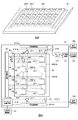
図2は、図1に示す撮像部22の構成を説明するための図である。そして、図2(a)はその構造を示す斜視図であり、図2(b)はその構成を示すブロック図である。
FIG. 2 is a diagram for explaining the configuration of the
図2(a)において、撮像部22は第1のチップ20および第2のチップ21を有している。第2のチップ21上に第1のチップ20が積層されている。第1のチップ20はマトリックス状に配列された複数の画素201を有しており、第1のチップ20は光入射側に配置されている(つまり、光学像の受光側に位置している)。
In FIG. 2A, the
第2のチップ21には、図2(b)に示す列走査回路213−a、213−bと行走査回路212などの画素駆動回路が形成されるとともに、前述のAF評価値検出部23が形成されている。
In the
このように、2つのチップに半導体を分けて配設し、第1のチップ20に画素201を形成し、第2のチップ21に画素駆動回路およびAF評価値検出部23を形成している。これにより、撮像素子102の周辺回路および画素部の製造プロセスを分けることができ、周辺回路における配線の細線化、高密度化による高速化、小型化、および高機能化を図ることができる。
As described above, the semiconductor is divided into two chips, the
図2(b)に示すように、第1のチップ20において、画素201はマトリクス状に配列されている。画素201は水平方向(行方向)において転送信号線203、リセット信号線204、及び行選択信号線205に接続され、垂直方向(列方向)において列信号線202−a、202−bに接続されている。なお、列信号線202−a、202−bの各々は読み出し行単位に応じて接続先が異なる。
As shown in FIG. 2B, in the
画像処理部24は、信号処理部104を有する。画素接続方式に関する説明については図3にて後述する。
The
第2のチップ21には、複数のカラムADCブロック211が備えられており、カラムADCブロック211は列信号線202−aまたは列信号線202−bに接続されている。さらに、第2のチップ21には、行走査回路212、列走査回路213−a、213−b、タイミング制御回路214、水平信号線215−a、215−b、切替スイッチ216、フレームメモリ217、及びAF評価値検出部23が備えられる。
The
タイミング制御回路214はシステム制御部50からの制御信号を受けて、行走査回路212、列走査回路213−a、213−b、及びカラムADCブロック211の動作タイミングを制御する。行走査回路212は各行の走査を行い、列走査回路213a、213bはそれぞれ各列の走査を行う。
The
水平信号線215−a、215−bは、それぞれ列走査回路213−a、213−bで制御されるタイミングに応じてカラムADCブロック211の出力信号(画像信号)を転送する。 The horizontal signal lines 215-a and 215-b transfer the output signal (image signal) of the column ADC block 211 according to the timing controlled by the column scanning circuits 213-a and 213-b, respectively.
フレームメモリ217は水平信号線215−bから出力される画像信号を一時的に記憶する。AF評価値検出部23はフレームメモリ217に記憶された画像信号に応じてAF評価値を検出(生成)して、当該AF評価値を制御部106に送る。切替スイッチ216は水平信号線215−bに出力される画像信号をAF評価値検出部23または信号処理部104のいずれか一方に選択的に出力するための切り替えスイッチである。水平信号線215−aに転送された画像信号は信号処理部104に与えられる。
The
次に撮像部22の構成及び動作について説明する。複数の画素201の各々の構成は共通であるが、図2(b)には1つの画素201だけ詳しく図示しているので、主にそれを参照して説明する。
Next, the configuration and operation of the
画素201の各々は、光電変換素子であるフォトダイオードPD、転送トランジスタM1、リセットトランジスタM2、増幅トランジスタM3、選択トランジスタM4、FD(フローティングディフュージョン)を有している。なお、図示の例では、トランジスタの各々はnチャネルMOSFET(MOS Field−Effect Transistor)である。
Each of the
転送トランジスタM1、リセットトランジスタM2、および選択トランジスタM4のゲートには、それぞれ転送信号線203、リセット信号線204、および行選択信号線205が接続されている。これら信号線203〜205は水平方向に延在し、同一行の画素が同時に駆動される。これによってライン順次動作型のローリングシャッタまたは全行同時動作型のグローバルシャッタの動作を制御することができる。さらに、選択トランジスタM4のソースには列信号線202−aまたは列信号線202−bが行単位で接続されている。
A
フォトダイオードPDは、光電変換によって生成された電荷を蓄積する。フォトダイオードPDのP側が接地され、N側が転送トランジスタM1のソースに接続されている。転送トランジスタM1がオン(ON)すると、フォトダイオードPDの電荷がFDに転送され、FDには寄生容量が存在するので、FDに転送された電荷が蓄積される。 The photodiode PD accumulates electric charges generated by photoelectric conversion. The P side of the photodiode PD is grounded, and the N side is connected to the source of the transfer transistor M1. When the transfer transistor M1 is turned on (ON), the charge of the photodiode PD is transferred to the FD, and since there is a parasitic capacitance in the FD, the charge transferred to the FD is accumulated.
増幅トランジスタM3のドレインには電源電圧Vddが印加され、そのゲートはFDに接続されている。増幅トランジスタM3は、FDの電荷(つまり、電圧)を増幅して電圧信号に変換する。選択トランジスタM4は、信号を読み出す画素を行単位で選択するためのものであり、そのドレインは増幅トランジスタM3のソースに接続されている。また、選択トランジスタM4のソースは列信号線202に接続されている。
A power supply voltage Vdd is applied to the drain of the amplification transistor M3, and its gate is connected to the FD. The amplification transistor M3 amplifies the charge (that is, voltage) of the FD and converts it into a voltage signal. The selection transistor M4 is for selecting a pixel from which a signal is read out in units of rows, and its drain is connected to the source of the amplification transistor M3. The source of the selection transistor M4 is connected to the
選択トランジスタM4がオンすると、FDの電圧に対応する電圧信号が列信号線202に出力される。リセットトランジスタM2のドレインには電源電圧Vddが印加され、そのソースはFDに接続されている。リセットトランジスタM2のオンによって、FDの電圧は電源電圧Vddにリセットされる。
When the selection transistor M4 is turned on, a voltage signal corresponding to the voltage of the FD is output to the
以下の説明では、撮像の際、列信号線202−aから水平信号線215−aを経由する出力経路をチャンネルCh1と呼び、列信号線202−bから水平信号線215−bを経由する出力経路をチャンネルCh2と呼ぶ。 In the following description, during imaging, an output path from the column signal line 202-a via the horizontal signal line 215-a is referred to as channel Ch1, and output from the column signal line 202-b via the horizontal signal line 215-b. The route is called channel Ch2.
チャンネルCh1から画像を取得する撮像を「メイン撮像」と称し、それにより得られる画像をメイン撮像画像と称する。チャンネルCh2から画像を取得する撮像を「サブ撮像」と称し、それにより得られる画像をサブ撮像画像と称する。メイン撮像画像の用途は、スキャンAEまたはライブビューである。サブ撮像画像は、多重出力モードではスキャンAE用となるが、フォーカス制御モードではAF評価値検出用となる。 Imaging for acquiring an image from the channel Ch1 is referred to as “main imaging”, and an image obtained thereby is referred to as a main captured image. Imaging for acquiring an image from the channel Ch2 is referred to as “sub-imaging”, and an image obtained thereby is referred to as a sub-captured image. The main captured image is used for scan AE or live view. The sub-captured image is for scan AE in the multiple output mode, but is for AF evaluation value detection in the focus control mode.
メイン撮像によるスキャンAE用またはライブビュー用の画像信号は列信号線202−aに出力され、サブ撮像によるスキャンAE用またはAF評価値検出用の画像信号は列信号線202−bに出力される。 An image signal for scan AE or live view by main imaging is output to the column signal line 202-a, and an image signal for scan AE or AF evaluation value detection by sub imaging is output to the column signal line 202-b. .
図3は、図2に示す第1のチップ20において列信号線202−aまたは202−bにおける画素選択を説明するための図である。
FIG. 3 is a diagram for explaining pixel selection in the column signal line 202-a or 202-b in the
図3においては、8行×6列の画素群が示されており、ここでは各画素はベイヤ配列されている。 In FIG. 3, a pixel group of 8 rows × 6 columns is shown, and here, each pixel is arranged in a Bayer array.
図1に示す操作部70の操作によってフォーカス制御モードになると、システム制御部50は、メイン撮像とサブ撮像とを同時(並行して)に行うことができるように、撮像部22における読み出し行を分ける。つまり、切替スイッチ216を切替制御して、水平信号線215−bをフレームメモリ217に接続する。
When the focus control mode is set by the operation of the
図3において、行番号1、2はサブ撮像のための行であり、これらの行に属する画素201を「第2の画素群」と呼称する。行番号3〜8はメイン撮像のための行であり、これらの行に属する画素201を「第1の画素群」と呼称する。第1の画素群と第2の画素群とは重複しない。図示の例では、読み出し走査が行単位で順次行われて、8行単位で繰り返し読み出し走査が行われることになる。
In FIG. 3, row numbers 1 and 2 are rows for sub-imaging, and the
サブ撮像では、フレームレート重視のため垂直同色4画素中3画素を間引き読み出しする。一方、メイン撮像では、画質重視のため垂直同色4画素中1画素を間引き3画素を加算する。 In sub-imaging, three out of four pixels of the same vertical color are skipped and read in order to emphasize the frame rate. On the other hand, in main imaging, 1 pixel out of 4 pixels of the same vertical color is thinned out and 3 pixels are added to emphasize image quality.
言い換えると、メイン撮像では第1の画素群を第1のフレームレートで読み出しを行う。サブ撮像においては、第2の画素群を第1のフレームレートより高速の第2のフレームレートで読み出しを行う。 In other words, in the main imaging, the first pixel group is read at the first frame rate. In sub-imaging, the second pixel group is read out at a second frame rate that is faster than the first frame rate.
このように、選択行ごとにメイン撮像とサブ撮像とを分けることによって、異なる電荷蓄積時間でデータサイズの異なるフレームレートの画像信号を取得することが可能となる。図3に示す例では、メイン撮像に対し、サブ撮像は3倍のフレームレートを持つことになる。例えば、メイン撮像のフレームレートを30fpsとした場合、サブ撮像のフレームレートは90fpsとなる。 As described above, by separating the main imaging and the sub imaging for each selected row, it is possible to acquire image signals of different frame rates with different data sizes in different charge accumulation times. In the example shown in FIG. 3, the sub imaging has a frame rate three times that of the main imaging. For example, when the main imaging frame rate is 30 fps, the sub-imaging frame rate is 90 fps.
列信号線202−a、202−bに出力された電圧信号(アナログ信号)は、カラムADCブロック211(図2)においてアナログ信号からデジタル信号(画像信号)に変換される。 The voltage signals (analog signals) output to the column signal lines 202-a and 202-b are converted from analog signals to digital signals (image signals) in the column ADC block 211 (FIG. 2).
カラムADCブロック211の出力である画像信号は、列走査回路213−aまたは列走査回路213−bによってカラムADCブロック211から水平信号線215−aまたは水平信号線215−bに読み出される。水平信号線215−aに読み出された画像信号は信号処理部104に送られる。
The image signal that is the output of the column ADC block 211 is read from the column ADC block 211 to the horizontal signal line 215-a or the horizontal signal line 215-b by the column scanning circuit 213-a or the column scanning circuit 213-b. The image signal read out to the horizontal signal line 215-a is sent to the
一方、水平信号線215−bに読み出された画像信号は、切替スイッチ216に出力され、システム制御部50からの制御信号に従って、信号処理部104またはフレームメモリ217に出力される。切替スイッチ216による切り替えはフレーム単位で行われる。
On the other hand, the image signal read to the horizontal signal line 215-b is output to the
多重出力モードにおいては、切替スイッチ216は、水平信号線215−bに出力された第2の画素群の信号の出力先を信号処理部104に切り替える。この場合、第1の画素群及び第2の画素群の画像信号は、それぞれ水平信号線215−a及び水平信号線215−bを通じて、並行して信号処理部104に出力される。
In the multiple output mode, the
フォーカス制御モードにおいては、切替スイッチ216は、水平信号線215−bに出力された第2の画素群の信号の出力先をフレームメモリ217に切り替える。この場合、第1の画素群の画像信号は、水平信号線215−aを通じて信号処理部104に出力されると共に、第2の画素群の画像信号は、水平信号線215−bを通じてフレームメモリ217に出力される。
In the focus control mode, the
AF評価モード(オートフォーカス制御モード)の際には、サブ撮像によるAF評価値検出用の画像信号は、水平信号線215−bから切替スイッチ216を介してフレームメモリ217に供給されて記録される。AF評価値検出部23は、フレームメモリ217に記録された画像信号におけるコントラスト情報に基づいてAF評価値を検出する。そして、このAF評価値はAF評価値検出部23からシステム制御部50に送られる。
In the AF evaluation mode (autofocus control mode), an image signal for AF evaluation value detection by sub imaging is supplied from the horizontal signal line 215-b to the
次に、スキャン型露出制御について説明する。ここでは、測光を3回行うスキャン型露出制御を例にとって説明する。 Next, scan type exposure control will be described. Here, a scan type exposure control in which photometry is performed three times will be described as an example.
予め決定された露出値の異なる3つの制御値Bv1,Bv2,Bv3によって、それぞれ測光が行われる。それぞれの制御値により得られるデジタルデータの平均輝度値をそれぞれY1,Y2,Y3とし、また目標の輝度値をYrefとする。3つの制御値ΔBv1,ΔBv2,ΔBv3は以下の数式1、2、3で求めることができる。
[数1]
ΔBv1=log2(Y1/Yref)
[数2]
ΔBv2=log2(Y2/Yref)
[数3]
ΔBv3=log2(Y3/Yref)
次に、制御値ΔBv1,ΔBv2,ΔBv3のそれぞれの絶対値である、ABS(ΔBv1),ABS(ΔBv2),ABS(ΔBv3)のうち、最も小さいものを元にして露出制御値BvSが求められる。例えば、ABS(ΔBv1),ABS(ΔBv2),ABS(ΔBv3)のうちでABS(ΔBv1)が一番小さい場合には、露出制御値BvSは数式4、5で求められる。ただしAv1,Tv1,Sv1はそれぞれ、測光の露出値が制御値Bv1であるときの絞り制御値、電子シャッタ制御値、撮像部22の感度制御値である。
[数4]
Bv1=Av1+Tv1−Sv1
[数5]
BvS=Bv1+ΔBv1
従って、一番小さいものがABS(ΔBv2)またはABS(ΔBv2)であれば、数式3、4においてBv1の代わりにBv2またはBv3が入り、ΔBv1の代わりにΔBv2またはΔBv3が入る。また、Av1,Tv1,Sv1の代わりにBv2またはBv3に対応する値が入る。ここで求められた露出制御値BvSが、初期露出値Bvsとして撮像部22へと送られ、絞り、シャッタが制御されて本露光撮影が行われる。
Photometry is performed using three control values Bv1, Bv2, and Bv3 having different exposure values. The average luminance value of the digital data obtained by each control value is Y1, Y2, Y3, respectively, and the target luminance value is Yref. The three control values ΔBv1, ΔBv2, and ΔBv3 can be obtained by the following formulas 1, 2, and 3.
[Equation 1]
ΔBv1 = log 2 (Y1 / Yref)
[Equation 2]
ΔBv2 = log 2 (Y2 / Yref)
[Equation 3]
ΔBv3 = log 2 (Y3 / Yref)
Next, the exposure control value BvS is obtained based on the smallest one of ABS (ΔBv1), ABS (ΔBv2), and ABS (ΔBv3), which are the absolute values of the control values ΔBv1, ΔBv2, and ΔBv3. For example, when ABS (ΔBv1) is the smallest among ABS (ΔBv1), ABS (ΔBv2), and ABS (ΔBv3), the exposure control value BvS is obtained by
[Equation 4]
Bv1 = Av1 + Tv1-Sv1
[Equation 5]
BvS = Bv1 + ΔBv1
Therefore, if the smallest one is ABS (ΔBv2) or ABS (ΔBv2), Bv2 or Bv3 is entered instead of Bv1 in
このスキャン型露出制御に従って、制御値Bv1、Bv2、Bv3によって撮像動作を行い、各々の平均輝度値Y1、Y2、Y3を迅速に求めることができれば、適正露出状態でのライブ表示開始までのタイムラグの短縮が可能となる。 If the imaging operation is performed with the control values Bv1, Bv2, and Bv3 according to the scan type exposure control and the respective average luminance values Y1, Y2, and Y3 can be quickly obtained, the time lag until the live display starts in the proper exposure state Shortening is possible.
ここでは、スキャン型露出制御を行う場合において3回の測光を行い、表示部28に撮像画像をプレビュー表示させる際の初期露出条件(初期露出値Bvs)を求める方法について述べた。しかし測光の回数は3回に限定されるものではなく、2回に減らしてもよいし、あるいは4回もしくは5回と増やしてもよい。図4,図5では、測光回数を2回とした場合を説明する。
Here, the method for obtaining the initial exposure condition (initial exposure value Bvs) when performing the photometry three times in the case of performing the scan type exposure control and displaying the preview of the captured image on the
図4は、撮影起動時におけるライブ表示開始の処理のフローチャートである。図4を含む以降の各フローチャートにおける各処理は、システム制御部50が不揮発性メモリ56に格納されたプログラムを実行することにより実現される。
FIG. 4 is a flowchart of live display start processing at the start of shooting. Each process in the following flowcharts including FIG. 4 is realized by the
このライブ表示開始では、撮影起動後、ライブ表示開始前に、測光回数2回のスキャンAE制御を行う。また、チャンネルCh2から出力されるサブ撮像画像を、AF評価値検出として使用するのではなく、ライブ表示開始前のAE動作を高速に実施するために使用する。なおスキャンAE実施の前提として、チャンネルCh1、Ch2での撮像感度が同一(あるいは同等)となるように制御され、絞りも同一とされる。 In this live display start, scanning AE control is performed twice after photometry is started and before live display is started. Further, the sub-captured image output from the channel Ch2 is not used for AF evaluation value detection, but is used for performing the AE operation before the start of live display at high speed. As a premise for performing the scan AE, the imaging sensitivities in the channels Ch1 and Ch2 are controlled to be the same (or equivalent), and the diaphragms are also the same.
まずステップS401では、システム制御部50は、撮像部22に電源を供給することで撮像電源をONにし、さらにシャッタ101、バリア105を開成すると共に、撮影レンズ103を初期位置に移動させる。
First, in step S401, the
ステップS402では、システム制御部50は、メイン撮像及びサブ撮像を並行して行う多重出力モードで動作させるための設定を行い、撮像部22等の駆動を開始させる。具体的には、システム制御部50は、切替スイッチ216によるチャンネルCh2の出力先の設定を信号処理部104とする。その際、システム制御部50は、前述のスキャン型露出制御における制御値Bv1,Bv2から導出される露光時間(シャッタスピード)T1、T2(T1>T2)の設定を、それぞれメイン撮像、サブ撮像に対して行う。
In step S402, the
以降、露光時間T2(第2の露出条件)にて露光した、第2の画素群から得られるサブ撮像画像を第2の画像P2と称し、露光時間T1(第1の露出条件)にて露光した、第1の画素群から得られるメイン撮像画像を第1の画像P1と称する。 Hereinafter, the sub-captured image obtained from the second pixel group exposed at the exposure time T2 (second exposure condition) is referred to as a second image P2, and is exposed at the exposure time T1 (first exposure condition). The main captured image obtained from the first pixel group is referred to as a first image P1.
次にシステム制御部50は、サブ撮像により露光時間T2にて露光した第2の画像P2の撮像部22からの読み出し(取り込み)動作が完了するのを待つ(ステップS403)。第2の画像P2の読み出し動作が完了したら(第2の取得ステップ)、システム制御部50は、読み出しにより取得した第2の画像P2に対する輝度情報である輝度評価値Y(P2)を、画像処理部24から取得する(ステップS404)。それと共に、システム制御部50は、動作モードをAF評価モードとし、切替スイッチ216によるチャンネルCh2の出力先の設定をフレームメモリ217とする。
Next, the
次にシステム制御部50は、メイン撮像により露光時間T1にて露光した第1の画像P1の撮像部22からの読み出し動作が完了するのを待つ(ステップS405)。第1の画像P1の読み出し動作が完了したら(第1の取得ステップ)、システム制御部50は、読み出しにより取得した第1の画像P1に対する輝度情報である輝度評価値Y(P1)を、画像処理部24から取得する(ステップS406)。
Next, the
次にシステム制御部50は、前述のスキャン型露出制御における演算(数式1〜5)に基づいて、制御値Bv1,Bv2から初期露出値Bvsを求める(ステップS407)。次にシステム制御部50は、この初期露出値BvS及び不揮発性メモリ56内に格納されたプログラム線図から、プレビュー表示させる際の初期露光時間T0を決定し、それを撮像部22に設定する(ステップS408)。
Next, the
次にシステム制御部50は、撮像部22から出力されたメイン撮像画像を、信号処理部104を経由して連続的に画像処理部24に転送し、表示用現像処理を施してメモリ32へ書きこむ。そしてシステム制御部50は、メモリ32内の画像をメモリ制御部15、D/A変換器13を介して表示部28に転送することで、ライブ表示を開始させ(ステップS409)、図4の処理を終了させる。
Next, the
次に、図5を用いて、図4の処理に対応する撮影起動後の撮像タイミングの詳細について説明する。 Next, details of the imaging timing after the start of imaging corresponding to the processing of FIG. 4 will be described using FIG.
図5は、ライブ表示開始の処理時のタイミングチャートである。図5において、PVDは表示用の垂直同期信号、VD1はチャンネルCh1におけるメイン撮像の垂直同期信号を表し、VD2はチャンネルCh2におけるサブ撮像の垂直同期信号を表している。時刻t507の前までは、撮像画像を表示部28に表示させていない状態である。
FIG. 5 is a timing chart at the time of live display start processing. In FIG. 5, PVD represents a vertical synchronizing signal for display, VD1 represents a vertical synchronizing signal for main imaging in the channel Ch1, and VD2 represents a vertical synchronizing signal for sub-imaging in the channel Ch2. Until time t507, the captured image is not displayed on the
サブ撮像により露光時間T2にて露光した第2の画像P2の読み出しは時刻t501にて完了し、その第2の画像P2から輝度評価値Y(P2)が画像処理部24内での演算により求められる。この後、動作モードはAF評価モードとなる。従って、時刻t501以降は、サブ撮像は本来のAF評価値検出用に用いられる。
Reading of the second image P2 exposed at the exposure time T2 by the sub imaging is completed at time t501, and the luminance evaluation value Y (P2) is obtained from the second image P2 by calculation in the
一方、サブ撮像と並行してメイン撮像により露光時間T1にて露光した第1の画像P1の読み出しは時刻t502にて完了し、その第1の画像P1から輝度評価値Y(P1)が画像処理部24内での演算により求められる(時刻t503)。 On the other hand, the reading of the first image P1 exposed at the exposure time T1 by the main imaging in parallel with the sub imaging is completed at time t502, and the luminance evaluation value Y (P1) is image-processed from the first image P1. It is obtained by calculation in the unit 24 (time t503).
時刻t503の後、輝度評価値Y(P1)、Y(P2)から、前述の演算式により初期露出値BvSが導出され、初期露出値BvS及びプログラム線図より初期露光時間T0が決定される(時刻t504)。 After time t503, the initial exposure value BvS is derived from the luminance evaluation values Y (P1) and Y (P2) by the above-described arithmetic expression, and the initial exposure time T0 is determined from the initial exposure value BvS and the program diagram ( Time t504).
この初期露光時間T0は、次のメイン撮像、すなわち次のライブ表示用の撮像の垂直期間から反映され、時刻t505から露光が開始される。その後、露光画像P0の読み出しが時刻t506で完了し、次の表示用の垂直同期信号PVDに合わせ、時刻t507からライブ表示を開始できる。 The initial exposure time T0 is reflected from the vertical period of the next main imaging, that is, the imaging for the next live display, and the exposure is started from time t505. Thereafter, reading of the exposure image P0 is completed at time t506, and live display can be started from time t507 in synchronization with the next vertical synchronizing signal PVD for display.
このように、スキャン型露出制御において、ライブ表示を用途にできるメイン撮像とAF評価値検出を用途にできるサブ撮像とを時間的に並行して行える仕組みを利用すると共に、メイン撮像よりもサブ撮像を高速のフレームレートとする。スキャン型露出制御動作において、露光時間T2は露光時間T1よりも短く、メイン撮像が長秒側、サブ撮像が短秒側となる。 In this way, in scan-type exposure control, a mechanism that allows main imaging that can be used for live display and sub-imaging that can be used for AF evaluation value detection in parallel is used, and sub-imaging is performed rather than main imaging. Is a high frame rate. In the scanning exposure control operation, the exposure time T2 is shorter than the exposure time T1, and the main imaging is on the long seconds side and the sub imaging is on the short seconds side.
メイン撮像及びサブ撮像のいずれにおける露光も、チャンネルCh1の1V期間(1垂直走査期間)内に完了するように制御される。従って、メイン撮像による第1の画像P1の取得が完了する前に、サブ撮像による第2の画像P2の取得が完了する。これにより、スキャン型露出制御動作に要する時間が短縮される。すなわち、従来では、ライブ表示用の撮像において、2V期間(2垂直走査期間)を要していたスキャン型露出制御を1V期間で完了することができる。 Exposure in both main imaging and sub imaging is controlled to be completed within 1 V period (one vertical scanning period) of channel Ch1. Accordingly, the acquisition of the second image P2 by the sub imaging is completed before the acquisition of the first image P1 by the main imaging is completed. Thereby, the time required for the scanning exposure control operation is shortened. That is, conventionally, the scanning type exposure control that required 2V period (2 vertical scanning periods) in imaging for live display can be completed in 1V period.
本実施の形態によれば、撮像画像を表示部28に表示させていない状態で、画像処理部24の信号処理部104による、第1の画像P1の取得と第2の画像P2の取得とが、時間的に並行して行われる。第1の画像P1は、第1のフレームレートで且つ第1の露出条件にて取得される。第2の画像P1は、第1のフレームレートよりも高速の第2のフレームレートで且つ、第1の露出条件(露光時間T1)よりも露光時間が短い第2の露出条件(露光時間T2)にて取得される。そして、取得された画像P1、P2から求められる輝度情報(Y(P1))、(Y(P2))に基づいて、表示部28に撮像画像を表示させる際の初期露出条件として初期露光時間T0が決定される。これにより、表示画質を落とすことなく、コストアップを回避しつつ、適正露出での画像表示開始までの時間を短縮することができる。従来のように外部測光センサを別途設ける必要がない点で、構成の複雑化やコストアップも回避でき、消費電力の点でも有利となる。
According to the present embodiment, acquisition of the first image P1 and acquisition of the second image P2 by the
また、時刻t501以降は、チャンネルCh2については本来のAF評価値検出用の動作が実施できる。従って、時刻t507でライブ表示が開始される前までに、撮影レンズ103を動作させてフォーカシング動作を完了させておくことで、ライブ表示開始時からピントの合った状態にしておくことが可能となる。また、シーケンシャルに画像を読み出す従来の方式に比べて、第1の画像P1,第2の画像P2の露光タイミングがほぼ同時化されることで、自動露出制御のための演算精度が向上するというメリットもある。
After time t501, the original AF evaluation value detection operation can be performed for channel Ch2. Therefore, by operating the photographing
また、第2の画素群から読み出される信号は、スキャンAEに用いられると共に、切替スイッチ216での切り替えによって、AF評価値検出部23によるAF評価値の生成(検出)にも用いられる。従って、第2の画素群がスキャンAE専用でないので、構成の複雑化を抑制できる。
The signal read from the second pixel group is used for scan AE and also for generation (detection) of an AF evaluation value by the AF evaluation
なお、スキャン型露出制御を行う場合において2回の測光を行い、初期露出条件を求める方法について述べたが、測光の回数は2回に限定されるものではない。撮像部22のダイナミックレンジ等を考慮し、第2の実施の形態でも説明するように、測光の回数を3回以上としてもよい。
In the case of performing the scan type exposure control, the method of obtaining the initial exposure condition by performing the photometry twice has been described, but the number of photometry is not limited to two. In consideration of the dynamic range of the
(第2の実施の形態)
上述した第1の実施の形態では、スキャン型露出制御を行う場合の測光の回数が2回であったが、第2の実施の形態では3回とする。また、チャンネルCh2において先に取り込みが完了した画像から輝度評価値Yの算出を行い、輝度評価値Yが満足な値であれば、切替スイッチ216におけるチャンネルCh2の信号の出力先をフレームメモリ217に直ちに切り替える。
(Second Embodiment)
In the first embodiment described above, the number of times of photometry when performing the scan type exposure control is two, but in the second embodiment, the number of times is three. Also, the luminance evaluation value Y is calculated from the image that has been previously captured in the channel Ch2, and if the luminance evaluation value Y is a satisfactory value, the output destination of the signal of the channel Ch2 in the
図6は、第2の実施の形態における撮影起動時におけるライブ表示開始の処理のフローチャートである。 FIG. 6 is a flowchart of live display start processing at the time of shooting activation according to the second embodiment.
システム制御部50は、ステップS601〜S604では、図4のステップS401〜S404と同様の処理を実行する。ただし、ステップS602では、前述のスキャン型露出制御における制御値Bv1から導出される露光時間T1の設定を、メイン撮像に対して行う。それと共に、制御値Bv2、Bv3から導出される露光時間T2、T3の設定を、サブ撮像に対して行う。露光時間Tの長短の関係は、T1>T3>T2である。サブ撮像に関しては、短秒側である露光時間T2による撮像を露光時間T3による撮像に先だって行う。
In steps S601 to S604, the
ステップS605では、システム制御部50は、ステップS604で取得した輝度評価値Y(P2)を目標輝度値Yrefと比較し、輝度評価値Y(P2)と目標輝度値Yrefとの差分d(P2)が所定範囲内であるか否かを判別する。
In step S605, the
その判別の結果、差分d(P2)が所定範囲外である場合は、システム制御部50は、サブ撮像により露光時間T3にて露光した第3の画像P3の撮像部22からの読み出し動作が完了するのを待つ(ステップS606)。ここで第3の画像P3は、第2のフレームレートで且つ、露光時間T3(第3の露出条件)にて露光した、第2の画素群から得られるサブ撮像画像である。第3の画像P3の読み出し動作が完了したら、システム制御部50は、読み出しにより取得した第3の画像P3に対する輝度評価値Y(P3)を、画像処理部24から取得する(ステップS607)。
As a result of the determination, if the difference d (P2) is outside the predetermined range, the
そして、システム制御部50は、取得した輝度評価値Y(P3)を目標輝度値Yrefと比較し、輝度評価値Y(P3)と目標輝度値Yrefとの差分d(P3)が所定範囲内であるか否かを判別する(ステップS608)。その判別の結果、差分d(P3)が所定範囲外である場合は、システム制御部50は、メイン撮像により露光時間T1にて露光した第1の画像P1の撮像部22からの読み出し動作が完了するのを待つ(ステップS609)。
Then, the
第1の画像P1の読み出し動作が完了したら、システム制御部50は、読み出しにより取得した第1の画像P1に対する輝度評価値Y(P1)を、画像処理部24から取得する(ステップS610)。そしてシステム制御部50は、スキャン型露出制御における演算(数式1〜5)に基づいて、制御値Bv1,Bv2、Bv3から初期露出値Bvsを求める(ステップS611)。
When the reading operation of the first image P1 is completed, the
ステップS611を経由してステップS612に移行した場合、システム制御部50は、ステップS611で求めた初期露出値BvS及び不揮発性メモリ56内に格納されたプログラム線図から、プレビュー表示させる際の初期露光時間T0を決定する。そしてシステム制御部50は、求めた初期露光時間T0を撮像部22に設定する。
When the process proceeds to step S612 via step S611, the
その後、システム制御部50は、ステップS613で、図4のステップS409と同様の処理を実行してライブ表示を開始させ、図6の処理を終了させる。
Thereafter, in step S613, the
一方、ステップS605の判別の結果、差分d(P2)が所定範囲内である場合は、システム制御部50は、動作モードをAF評価モードとし、本来のAF評価値検出用の動作を開始し(ステップS614)、処理をステップS612に移行させる。ステップS608の判別の結果、差分d(P3)が所定範囲内である場合も、システム制御部50は、動作モードをAF評価モードとし、本来のAF評価値検出用の動作を開始し(ステップS614)、処理をステップS612に移行させる。
On the other hand, if the difference d (P2) is within the predetermined range as a result of the determination in step S605, the
ステップS614を経由してステップS612に移行した場合、ステップS612では、システム制御部50は、初期露出値BvSを求めることなく初期露光時間T0を決定しそれを撮像部22に設定する。すなわち、処理がステップS605→S614→S612と移行した場合、システム制御部50は、差分d(P2)に基づいて初期露光時間T0を決定する。一方、処理がステップS608→S614→S612と移行した場合、システム制御部50は、差分d(P3)に基づいて初期露光時間T0を決定する。
When the process proceeds to step S612 via step S614, in step S612, the
次に、図7を用いて、図6における処理がステップS611→S612と移行した場合に対応する撮影起動後の撮像タイミングの詳細について説明する。 Next, with reference to FIG. 7, the details of the imaging timing after the start of imaging corresponding to the case where the process in FIG. 6 has shifted from step S611 to S612 will be described.
図7は、ライブ表示開始の処理時のタイミングチャートである。 FIG. 7 is a timing chart at the time of live display start processing.
サブ撮像により露光時間T2にて露光した第2の画像P2の読み出しは時刻t701にて完了し、その第2の画像P2から輝度評価値Y(P2)が画像処理部24内での演算により求められる。露光時間T2によるサブ撮像の後に露光時間T3によるサブ撮像が開始される。サブ撮像により露光時間T3にて露光した第3の画像P3の読み出しは時刻t702にて完了し、その第3の画像P3から輝度評価値Y(P3)が画像処理部24内での演算により求められる。
Reading of the second image P2 exposed at the exposure time T2 by the sub imaging is completed at time t701, and the luminance evaluation value Y (P2) is obtained from the second image P2 by calculation in the
一方、露光時間T2によるサブ撮像及び露光時間T3によるサブ撮像と並行して、露光時間T1によるメイン撮像がなされる。メイン撮像により露光時間T1にて露光した第1の画像P1の読み出しは時刻t703にて完了し、その第1の画像P1から輝度評価値Y(P1)が画像処理部24内での演算により求められる(時刻t704)。
On the other hand, main imaging with exposure time T1 is performed in parallel with sub imaging with exposure time T2 and sub imaging with exposure time T3. Reading of the first image P1 exposed at the exposure time T1 by the main imaging is completed at time t703, and the luminance evaluation value Y (P1) is obtained from the first image P1 by calculation in the
その後、求められた輝度評価値Y(P1)、Y(P2)、Y(P3)から、前述のスキャン型露出制御の演算式により初期露出値BvSが導出され、初期露出値BvS及びプログラム線図より初期露光時間T0が決定される(時刻t705)。 Thereafter, an initial exposure value BvS is derived from the obtained luminance evaluation values Y (P1), Y (P2), and Y (P3) by the above-described arithmetic expression of the scanning exposure control, and the initial exposure value BvS and the program diagram are displayed. Thus, the initial exposure time T0 is determined (time t705).
この初期露光時間T0は、次のメイン撮像、すなわちライブ表示用の撮像の垂直期間から反映され、時刻t706から露光が開始される。その後、露光画像P0の読み出しが時刻t707で完了し、次の表示用の垂直同期信号PVDに合わせ、時刻t708からライブ表示を開始できる。 The initial exposure time T0 is reflected from the vertical period of the next main imaging, that is, the imaging for live display, and the exposure is started from time t706. Thereafter, reading of the exposure image P0 is completed at time t707, and live display can be started from time t708 in time with the next vertical synchronizing signal PVD for display.
次に、図8を用いて、図6における処理がステップS605→S614→S612と移行した場合に対応する撮影起動後の撮像タイミングの詳細について説明する。 Next, with reference to FIG. 8, the details of the imaging timing after the start of imaging corresponding to the case where the process in FIG. 6 has shifted from step S605 to S614 to S612 will be described.
図8は、ライブ表示開始の処理時のタイミングチャートである。 FIG. 8 is a timing chart at the time of live display start processing.
サブ撮像により露光時間T2にて露光した第2の画像P2の読み出しは時刻t801にて完了し、その第2の画像P2から輝度評価値Y(P2)が画像処理部24内での演算により求められる。この輝度評価値Y(P2)と目標輝度値Yrefとの差分d(P2)が所定範囲内であったので、差分d(P2)に基づいて初期露光時間T0が決定される。
Reading of the second image P2 exposed at the exposure time T2 by the sub imaging is completed at time t801, and the luminance evaluation value Y (P2) is obtained from the second image P2 by calculation in the
従って、これ以降のスキャン型露出制御は不要となり、露光時間T3によるサブ撮像も必要ではなくなる。そこで、時刻t802において、動作モードがAF評価モードとなり、本来のAF評価値の取得が指示される。そして時刻t803からAF制御が可能となる。ライブ表示用の露光は時刻t805から開始される。時刻t806で露光画像P0の読み出しが完了する。ライブ表示の開始が可能となるのは次の表示用の垂直同期信号PVDのタイミングとなるt807以降となる。 Accordingly, the subsequent scan-type exposure control is unnecessary, and sub-imaging with the exposure time T3 is not necessary. Therefore, at time t802, the operation mode becomes the AF evaluation mode, and an acquisition of the original AF evaluation value is instructed. Then, AF control is possible from time t803. The exposure for live display starts from time t805. Reading of the exposure image P0 is completed at time t806. The live display can be started after t807, which is the timing of the next display vertical synchronizing signal PVD.
一方、図6における処理がステップS608→S614→S612と移行した場合、
サブ撮像により露光時間T3にて露光した第3の画像P3の読み出しは時刻t901にて完了する。従って、メイン撮像による第1の画像P1の取得が完了する前に、サブ撮像による後に露光がなされる第3の画像P3の取得が完了する。そして第3の画像P3から輝度評価値Y(P3)が求められる。この輝度評価値Y(P3)と目標輝度値Yrefとの差分d(P3)が所定範囲内であったので、差分d(P3)に基づいて初期露光時間T0が決定される。
On the other hand, when the process in FIG. 6 proceeds from step S608 to S614 to S612,
Reading of the third image P3 exposed at the exposure time T3 by the sub imaging is completed at time t901. Therefore, before the acquisition of the first image P1 by the main imaging is completed, the acquisition of the third image P3 that is exposed after the sub imaging is completed. Then, the luminance evaluation value Y (P3) is obtained from the third image P3. Since the difference d (P3) between the luminance evaluation value Y (P3) and the target luminance value Yref is within a predetermined range, the initial exposure time T0 is determined based on the difference d (P3).
このように、短秒側となるサブ撮像による画像P2、P3の取得は、長秒側となるメイン撮像による画像P1の取得よりも高速のフレームレートで行われ、しかもチャンネルCh1の1V期間内に完了する。これにより、従来では3V期間を要していたスキャン型露出制御が、本実施の形態では1V期間で完了する。 As described above, the acquisition of the images P2 and P3 by the sub imaging on the short second side is performed at a higher frame rate than the acquisition of the image P1 by the main imaging on the long second side, and within the 1V period of the channel Ch1. Complete. Thereby, scan-type exposure control, which conventionally required a 3V period, is completed in a 1V period in the present embodiment.
また、第1の画像P1よりも早く取り込みが完了する第2の画像P2または第3の画像P3から輝度評価値Yの算出を行い、輝度評価値Yと目標輝度値Yrefとの差分dが所定範囲内であれば直ちにAF動作へ移行する。従って、AF動作の開始タイミングを前倒しすることが可能となる。さらに、差分dが所定範囲内であれば、メイン撮像の露光途中であっても、スキャン型露出のために実施していたメイン撮像に対しても露光途中で初期露光時間T0を決定可能となるため、適正露光による表示開始までの時間短縮効果が大きい。 In addition, the luminance evaluation value Y is calculated from the second image P2 or the third image P3 that has been captured earlier than the first image P1, and the difference d between the luminance evaluation value Y and the target luminance value Yref is predetermined. If it is within the range, the operation immediately shifts to the AF operation. Therefore, it is possible to advance the start timing of the AF operation. Further, if the difference d is within a predetermined range, the initial exposure time T0 can be determined during the exposure for the main imaging performed for the scan type exposure even during the exposure for the main imaging. Therefore, the effect of shortening the time until the start of display by appropriate exposure is great.
また、画像P2、P3のうち短秒側の第2の画像P2の読み出しを先行させることにより、高輝度下においてはより迅速にライブ表示及びAF動作を開始することができる。 In addition, by performing reading of the second image P2 on the short second side among the images P2 and P3, live display and AF operation can be started more quickly under high luminance.
本実施の形態によれば、適正露出での画像表示開始までの時間を短縮することに関し、第1の実施の形態と同様の効果を奏することができる。しかしそれだけでなく、第2の画像P2または第3の画像P3から算出される輝度評価値Yが満足する値である場合は、画像P1の取得を必要とすることなく初期露光時間T0を決定できるので、画像表示開始までの時間短縮に一層寄与する。特に、サブ撮像においては、短秒側の第2の画像P2の読み出しが先になされるので、大きな時間短縮効果を得る可能性を高めることができる。 According to the present embodiment, the same effect as that of the first embodiment can be achieved with respect to shortening the time until the start of image display with appropriate exposure. However, in addition to this, when the luminance evaluation value Y calculated from the second image P2 or the third image P3 is a satisfactory value, the initial exposure time T0 can be determined without requiring acquisition of the image P1. This further contributes to shortening the time until image display starts. In particular, in the sub-imaging, the second image P2 on the short second side is read first, so that the possibility of obtaining a large time reduction effect can be increased.
なお、第1、第2の実施の形態において、撮影起動からライブビュー開始までのシーケンスについて説明したが、ライブビューに限らず、起動直後の動画撮影時などにおけるタイムラグ短縮にも有効である。光学ファインダー使用の撮影時のタイムラグも短縮される。 In the first and second embodiments, the sequence from the start of shooting to the start of live view has been described. However, the sequence is not limited to live view, and is effective for shortening the time lag at the time of moving image shooting immediately after startup. The time lag when shooting using the optical viewfinder is also shortened.
なお、第2の実施の形態において、図6の処理がステップS608→S614→S612と移行した場合であっても、差分d(P3)でなく差分d(P2)に基づいて初期露光時間T0を決定するという構成を採用することは可能である。 In the second embodiment, even when the process of FIG. 6 proceeds from step S608 to S614 to S612, the initial exposure time T0 is set based on the difference d (P2) instead of the difference d (P3). It is possible to adopt a configuration of determining.
なお、第2の実施の形態においては、サブ撮像は露光時間の異なる画像P2、P3の2つを対象としたが、チャンネルCh1の1V期間内に3つ以上の画像を露光・読み出しの対象としてもよい。その場合、大きな時間短縮効果を得られやすくするためには、露光時間の最も短い(短秒の)露出条件での画像の取得を最も早く開始するのが望ましい。 In the second embodiment, the sub imaging is performed on two images P2 and P3 having different exposure times. However, three or more images are targeted for exposure / readout within the 1V period of the channel Ch1. Also good. In this case, in order to easily obtain a large time shortening effect, it is desirable to start acquisition of an image under the exposure condition with the shortest exposure time (short seconds) first.
なお、第1、第2の実施の形態のように、ライブ表示用の撮像とは別にフレームレートの高い撮像を撮像部22で並行して取得し、そのデータから測光評価値を高速に出力する構成であれば、例示の構成以外も採用可能である。従って、画素群の分け方も、例示のような第1、第2の画素群という分け方に限定されず、重複しないように複数画素群に分ければよい。また、第1のチップ20において、画素201はマトリクス状に配列される構成に限定されない。
Note that, as in the first and second embodiments, imaging with a high frame rate is acquired in parallel by the
また、例えば、短秒側のサブ撮像においてはメイン撮像によるライブ表示用画像の画角に対して中央部を切り出すように画角を狭めて取り込んでもよい。すなわち、サブ撮像で用いる画素群は、メイン撮像で用いる画素群に対して行で分けるのではなく、画素201の配設範囲の中央部を切り出した狭画角としてもよい。このように構成すれば、画像読み出しにかかる時間をさらに短縮することができるだけでなく、撮影レンズ103が収納状態から撮影初期位置に移動するまでに発生するケラレが露出制御に与える影響を軽減できるというメリットがある。
Further, for example, in the sub-imaging on the short-second side, the image may be captured with the angle of view narrowed so that the central portion is cut out with respect to the angle of view of the live display image by the main imaging. That is, the pixel group used for the sub-imaging may not be divided into rows with respect to the pixel group used for the main imaging, but may have a narrow angle of view cut out from the center of the arrangement range of the
なお、本発明は、以下の処理を実行することによっても実現される。即ち、上述した実施形態の機能を実現するソフトウェア(プログラム)をネットワーク又は各種記憶媒体を介してシステム或いは装置に供給し、そのシステム或いは装置のコンピュータ(又はCPUやMPU等)がプログラムコードを読み出して実行する処理である。この場合、そのプログラム、及び該プログラムを記憶した記憶媒体は本発明を構成することになる。 The present invention is also realized by executing the following processing. That is, software (program) that realizes the functions of the above-described embodiments is supplied to a system or apparatus via a network or various storage media, and a computer (or CPU, MPU, etc.) of the system or apparatus reads the program code. It is a process to be executed. In this case, the program and the storage medium storing the program constitute the present invention.
以上、本発明をその好適な実施形態に基づいて詳述してきたが、本発明はこれら特定の実施形態に限られるものではなく、この発明の要旨を逸脱しない範囲の様々な形態も本発明に含まれる。上述の実施形態の一部を適宜組み合わせてもよい。 Although the present invention has been described in detail based on preferred embodiments thereof, the present invention is not limited to these specific embodiments, and various forms within the scope of the present invention are also included in the present invention. included. A part of the above-described embodiments may be appropriately combined.
22 撮像部
24 画像処理部
50 システム制御部
201 画素
P1 第1の画像
P2 第2の画像
Y 輝度評価値
22
Claims (12)
前記撮像素子の前記複数の画素のうち第1の画素群から読み出される信号から第1の画像を取得する第1の取得手段と、
前記撮像素子の前記複数の画素のうち前記第1の画素群と重複しない第2の画素群から読み出される信号から第2の画像を取得する第2の取得手段と、
前記第1の取得手段及び前記第2の取得手段のそれぞれによる画像の取得を制御する制御手段と、を有し、
前記制御手段は、撮像画像を表示部に表示させていない状態で、第1のフレームレートで且つ第1の露出条件にて、前記第1の取得手段に前記第1の画像を取得させることと、前記第1のフレームレートよりも高速の第2のフレームレートで且つ前記第1の露出条件よりも露光時間が短い第2の露出条件にて、前記第2の取得手段に前記第2の画像を取得させることとを、時間的に並行して行わせると共に、前記第1の取得手段により取得された前記第1の画像から求められる輝度情報と、前記第2の取得手段により取得された前記第2の画像から求められる輝度情報とに基づいて、前記表示部に撮像画像を表示させる際の初期露出条件を決定することを特徴とする撮像装置。 An image sensor having a plurality of pixels that output signals according to an optical image;
First acquisition means for acquiring a first image from a signal read from a first pixel group among the plurality of pixels of the imaging element;
Second acquisition means for acquiring a second image from a signal read from a second pixel group that does not overlap with the first pixel group among the plurality of pixels of the imaging element;
Control means for controlling image acquisition by each of the first acquisition means and the second acquisition means,
The control unit causes the first acquisition unit to acquire the first image at a first frame rate and a first exposure condition in a state where the captured image is not displayed on the display unit. The second image is sent to the second acquisition means at a second frame rate that is faster than the first frame rate and under a second exposure condition that has an exposure time shorter than the first exposure condition. And obtaining the luminance information obtained from the first image acquired by the first acquisition means, and the acquired by the second acquisition means An imaging apparatus, wherein an initial exposure condition for displaying a captured image on the display unit is determined based on luminance information obtained from a second image.
前記制御手段は、撮像画像を前記表示部に表示させていない状態で、前記第2の取得手段により取得された前記第2の画像から求めた輝度情報が所定範囲内であった場合は、前記第2の取得手段に前記第3の画像を取得させることなく、前記第2の画素群から読み出される信号の出力先を前記第2の取得手段から前記生成手段に切り替えるよう制御することを特徴とする請求項3〜6のいずれか1項に記載の撮像装置。 The image sensor has a generation unit that generates an evaluation value used when performing autofocus control based on a signal read from the second pixel group,
When the luminance information obtained from the second image acquired by the second acquisition unit is within a predetermined range in a state where the captured image is not displayed on the display unit, Controlling that the output destination of the signal read from the second pixel group is switched from the second acquisition unit to the generation unit without causing the second acquisition unit to acquire the third image. The imaging device according to any one of claims 3 to 6.
前記撮像素子の前記複数の画素のうち第1の画素群から読み出される信号から第1の画像を取得する第1の取得ステップと、
前記撮像素子の前記複数の画素のうち前記第1の画素群と重複しない第2の画素群から読み出される信号から第2の画像を取得する第2の取得ステップと、
前記第1の取得ステップ及び前記第2の取得ステップのそれぞれによる画像の取得を制御する制御ステップと、を有し、
前記制御ステップは、撮像画像を表示部に表示させていない状態で、第1のフレームレートで且つ第1の露出条件にて、前記第1の取得ステップに前記第1の画像を取得させることと、前記第1のフレームレートよりも高速の第2のフレームレートで且つ前記第1の露出条件よりも露光時間が短い第2の露出条件にて、前記第2の取得ステップに前記第2の画像を取得させることとを、時間的に並行して行わせると共に、前記第1の取得ステップにより取得された前記第1の画像から求められる輝度情報と、前記第2の取得ステップにより取得された前記第2の画像から求められる輝度情報とに基づいて、前記表示部に撮像画像を表示させる際の初期露出条件を決定することを特徴とする撮像装置の制御方法。 A method for controlling an imaging apparatus including an imaging device having a plurality of pixels that output a signal according to an optical image,
A first acquisition step of acquiring a first image from a signal read from a first pixel group among the plurality of pixels of the image sensor;
A second acquisition step of acquiring a second image from a signal read from a second pixel group that does not overlap with the first pixel group among the plurality of pixels of the imaging element;
A control step for controlling image acquisition by each of the first acquisition step and the second acquisition step,
The control step causes the first acquisition step to acquire the first image at a first frame rate and a first exposure condition in a state where the captured image is not displayed on the display unit. In the second acquisition step, the second image is acquired at a second frame rate that is higher than the first frame rate and under a second exposure condition that has an exposure time shorter than the first exposure condition. And acquiring the luminance information obtained from the first image acquired in the first acquisition step and the acquired in the second acquisition step. A control method for an imaging apparatus, comprising: determining an initial exposure condition when displaying a captured image on the display unit based on luminance information obtained from a second image.
Priority Applications (1)
| Application Number | Priority Date | Filing Date | Title |
|---|---|---|---|
| JP2014051585A JP6066949B2 (en) | 2014-03-14 | 2014-03-14 | Imaging apparatus, control method therefor, and program |
Applications Claiming Priority (1)
| Application Number | Priority Date | Filing Date | Title |
|---|---|---|---|
| JP2014051585A JP6066949B2 (en) | 2014-03-14 | 2014-03-14 | Imaging apparatus, control method therefor, and program |
Publications (2)
| Publication Number | Publication Date |
|---|---|
| JP2015177301A JP2015177301A (en) | 2015-10-05 |
| JP6066949B2 true JP6066949B2 (en) | 2017-01-25 |
Family
ID=54256088
Family Applications (1)
| Application Number | Title | Priority Date | Filing Date |
|---|---|---|---|
| JP2014051585A Active JP6066949B2 (en) | 2014-03-14 | 2014-03-14 | Imaging apparatus, control method therefor, and program |
Country Status (1)
| Country | Link |
|---|---|
| JP (1) | JP6066949B2 (en) |
Families Citing this family (3)
| Publication number | Priority date | Publication date | Assignee | Title |
|---|---|---|---|---|
| JP6596349B2 (en) * | 2016-02-04 | 2019-10-23 | オリンパス株式会社 | IMAGING DEVICE AND IMAGING DEVICE CONTROL METHOD |
| JP6924908B2 (en) | 2018-09-27 | 2021-08-25 | 富士フイルム株式会社 | Image sensor, image sensor, image data output method, and program |
| JP2022020382A (en) | 2020-07-20 | 2022-02-01 | キヤノン株式会社 | Imaging apparatus, method for controlling the same, and program |
Family Cites Families (4)
| Publication number | Priority date | Publication date | Assignee | Title |
|---|---|---|---|---|
| JP4830270B2 (en) * | 2004-06-14 | 2011-12-07 | ソニー株式会社 | Solid-state imaging device and signal processing method for solid-state imaging device |
| JP4735964B2 (en) * | 2005-10-26 | 2011-07-27 | ソニー株式会社 | Imaging device |
| US8031258B2 (en) * | 2006-10-04 | 2011-10-04 | Omnivision Technologies, Inc. | Providing multiple video signals from single sensor |
| JP2011182304A (en) * | 2010-03-03 | 2011-09-15 | Renesas Electronics Corp | Imaging apparatus and method for controlling the same |
-
2014
- 2014-03-14 JP JP2014051585A patent/JP6066949B2/en active Active
Also Published As
| Publication number | Publication date |
|---|---|
| JP2015177301A (en) | 2015-10-05 |
Similar Documents
| Publication | Publication Date | Title |
|---|---|---|
| US10530986B2 (en) | Image capturing apparatus, image capturing method, and storage medium | |
| CN109474781B (en) | Image pickup apparatus, control method for image pickup apparatus, and recording medium | |
| US9924094B2 (en) | Image pickup apparatus capable of changing drive mode and image signal control method | |
| JP6066949B2 (en) | Imaging apparatus, control method therefor, and program | |
| JP2008109485A (en) | Imaging apparatus and imaging control method | |
| JP6296767B2 (en) | Imaging apparatus and image signal processing method | |
| JP2017194558A (en) | Imaging device and imaging method | |
| JP4637029B2 (en) | Imaging apparatus and control method thereof | |
| JP7277263B2 (en) | Imaging device | |
| JP5452269B2 (en) | Imaging device | |
| US20210274110A1 (en) | Image capture apparatus and control method thereof | |
| JP6207360B2 (en) | Imaging apparatus and image signal processing method | |
| JP2010107662A (en) | Imaging apparatus, range-finding device and range-finding method | |
| JP2018081224A (en) | Imaging device and control method thereof | |
| US10462360B2 (en) | Image capturing apparatus and control method utilizing an image sensor with two-dimensional pixels and pixel signal storing unit | |
| JP6759088B2 (en) | Imaging device and its control method and program | |
| JP5127510B2 (en) | IMAGING DEVICE AND IMAGING DEVICE CONTROL METHOD | |
| US20150085172A1 (en) | Image capturing apparatus and control method thereof | |
| JP7027133B2 (en) | Focus detection device and focus detection method | |
| US10277800B2 (en) | Image pickup apparatus with focus detection technique, control method therefor, and storage medium | |
| JP2022191894A (en) | Imaging apparatus | |
| JP2017034567A (en) | Imaging apparatus | |
| JP2022044285A (en) | Detection device and detection method | |
| JP2015126386A (en) | Image pickup device, and control method and program of the same | |
| JP2023121622A (en) | Detection apparatus and detection method |
Legal Events
| Date | Code | Title | Description |
|---|---|---|---|
| A621 | Written request for application examination |
Free format text: JAPANESE INTERMEDIATE CODE: A621 Effective date: 20160406 |
|
| A977 | Report on retrieval |
Free format text: JAPANESE INTERMEDIATE CODE: A971007 Effective date: 20161114 |
|
| TRDD | Decision of grant or rejection written | ||
| A01 | Written decision to grant a patent or to grant a registration (utility model) |
Free format text: JAPANESE INTERMEDIATE CODE: A01 Effective date: 20161122 |
|
| A61 | First payment of annual fees (during grant procedure) |
Free format text: JAPANESE INTERMEDIATE CODE: A61 Effective date: 20161220 |
|
| R151 | Written notification of patent or utility model registration |
Ref document number: 6066949 Country of ref document: JP Free format text: JAPANESE INTERMEDIATE CODE: R151 |