JP6062342B2 - Tandem media tray with intermediate tray sensor - Google Patents
Tandem media tray with intermediate tray sensor Download PDFInfo
- Publication number
- JP6062342B2 JP6062342B2 JP2013221598A JP2013221598A JP6062342B2 JP 6062342 B2 JP6062342 B2 JP 6062342B2 JP 2013221598 A JP2013221598 A JP 2013221598A JP 2013221598 A JP2013221598 A JP 2013221598A JP 6062342 B2 JP6062342 B2 JP 6062342B2
- Authority
- JP
- Japan
- Prior art keywords
- tray
- sensor
- sliding plate
- stack
- media
- Prior art date
- Legal status (The legal status is an assumption and is not a legal conclusion. Google has not performed a legal analysis and makes no representation as to the accuracy of the status listed.)
- Expired - Fee Related
Links
Images


Classifications
-
- B—PERFORMING OPERATIONS; TRANSPORTING
- B65—CONVEYING; PACKING; STORING; HANDLING THIN OR FILAMENTARY MATERIAL
- B65H—HANDLING THIN OR FILAMENTARY MATERIAL, e.g. SHEETS, WEBS, CABLES
- B65H1/00—Supports or magazines for piles from which articles are to be separated
- B65H1/28—Supports or magazines for piles from which articles are to be separated compartmented to receive piles side-by-side
-
- B—PERFORMING OPERATIONS; TRANSPORTING
- B65—CONVEYING; PACKING; STORING; HANDLING THIN OR FILAMENTARY MATERIAL
- B65H—HANDLING THIN OR FILAMENTARY MATERIAL, e.g. SHEETS, WEBS, CABLES
- B65H7/00—Controlling article feeding, separating, pile-advancing, or associated apparatus, to take account of incorrect feeding, absence of articles, or presence of faulty articles
- B65H7/02—Controlling article feeding, separating, pile-advancing, or associated apparatus, to take account of incorrect feeding, absence of articles, or presence of faulty articles by feelers or detectors
- B65H7/04—Controlling article feeding, separating, pile-advancing, or associated apparatus, to take account of incorrect feeding, absence of articles, or presence of faulty articles by feelers or detectors responsive to absence of articles, e.g. exhaustion of pile
-
- G—PHYSICS
- G03—PHOTOGRAPHY; CINEMATOGRAPHY; ANALOGOUS TECHNIQUES USING WAVES OTHER THAN OPTICAL WAVES; ELECTROGRAPHY; HOLOGRAPHY
- G03G—ELECTROGRAPHY; ELECTROPHOTOGRAPHY; MAGNETOGRAPHY
- G03G15/00—Apparatus for electrographic processes using a charge pattern
- G03G15/65—Apparatus which relate to the handling of copy material
- G03G15/6502—Supplying of sheet copy material; Cassettes therefor
- G03G15/6508—Automatic supply devices interacting with the rest of the apparatus, e.g. selection of a specific cassette
-
- B—PERFORMING OPERATIONS; TRANSPORTING
- B65—CONVEYING; PACKING; STORING; HANDLING THIN OR FILAMENTARY MATERIAL
- B65H—HANDLING THIN OR FILAMENTARY MATERIAL, e.g. SHEETS, WEBS, CABLES
- B65H2301/00—Handling processes for sheets or webs
- B65H2301/40—Type of handling process
- B65H2301/42—Piling, depiling, handling piles
- B65H2301/422—Handling piles, sets or stacks of articles
- B65H2301/4225—Handling piles, sets or stacks of articles in or on special supports
- B65H2301/42254—Boxes; Cassettes; Containers
- B65H2301/422548—Boxes; Cassettes; Containers filling or loading process
-
- B—PERFORMING OPERATIONS; TRANSPORTING
- B65—CONVEYING; PACKING; STORING; HANDLING THIN OR FILAMENTARY MATERIAL
- B65H—HANDLING THIN OR FILAMENTARY MATERIAL, e.g. SHEETS, WEBS, CABLES
- B65H2301/00—Handling processes for sheets or webs
- B65H2301/40—Type of handling process
- B65H2301/42—Piling, depiling, handling piles
- B65H2301/422—Handling piles, sets or stacks of articles
- B65H2301/4226—Delivering, advancing piles
- B65H2301/42266—Delivering, advancing piles by acting on edge of the pile for moving it along a surface, e.g. pushing
-
- B—PERFORMING OPERATIONS; TRANSPORTING
- B65—CONVEYING; PACKING; STORING; HANDLING THIN OR FILAMENTARY MATERIAL
- B65H—HANDLING THIN OR FILAMENTARY MATERIAL, e.g. SHEETS, WEBS, CABLES
- B65H2405/00—Parts for holding the handled material
- B65H2405/10—Cassettes, holders, bins, decks, trays, supports or magazines for sheets stacked substantially horizontally
- B65H2405/11—Parts and details thereof
- B65H2405/114—Side, i.e. portion parallel to the feeding / delivering direction
-
- B—PERFORMING OPERATIONS; TRANSPORTING
- B65—CONVEYING; PACKING; STORING; HANDLING THIN OR FILAMENTARY MATERIAL
- B65H—HANDLING THIN OR FILAMENTARY MATERIAL, e.g. SHEETS, WEBS, CABLES
- B65H2405/00—Parts for holding the handled material
- B65H2405/10—Cassettes, holders, bins, decks, trays, supports or magazines for sheets stacked substantially horizontally
- B65H2405/15—Large capacity supports arrangements
-
- B—PERFORMING OPERATIONS; TRANSPORTING
- B65—CONVEYING; PACKING; STORING; HANDLING THIN OR FILAMENTARY MATERIAL
- B65H—HANDLING THIN OR FILAMENTARY MATERIAL, e.g. SHEETS, WEBS, CABLES
- B65H2511/00—Dimensions; Position; Numbers; Identification; Occurrences
- B65H2511/50—Occurence
- B65H2511/51—Presence
-
- B—PERFORMING OPERATIONS; TRANSPORTING
- B65—CONVEYING; PACKING; STORING; HANDLING THIN OR FILAMENTARY MATERIAL
- B65H—HANDLING THIN OR FILAMENTARY MATERIAL, e.g. SHEETS, WEBS, CABLES
- B65H2511/00—Dimensions; Position; Numbers; Identification; Occurrences
- B65H2511/50—Occurence
- B65H2511/515—Absence
-
- B—PERFORMING OPERATIONS; TRANSPORTING
- B65—CONVEYING; PACKING; STORING; HANDLING THIN OR FILAMENTARY MATERIAL
- B65H—HANDLING THIN OR FILAMENTARY MATERIAL, e.g. SHEETS, WEBS, CABLES
- B65H2513/00—Dynamic entities; Timing aspects
- B65H2513/40—Movement
-
- B—PERFORMING OPERATIONS; TRANSPORTING
- B65—CONVEYING; PACKING; STORING; HANDLING THIN OR FILAMENTARY MATERIAL
- B65H—HANDLING THIN OR FILAMENTARY MATERIAL, e.g. SHEETS, WEBS, CABLES
- B65H2801/00—Application field
- B65H2801/03—Image reproduction devices
- B65H2801/06—Office-type machines, e.g. photocopiers
Description
本明細書の実施形態は、一般に印刷装置などの媒体のシートを供給する装置に関し、より具体的には、隣接する媒体シートのスタック間に仕切り板を必要としない、(複数の媒体シートのスタックを保持する)タンデム式媒体トレイに関する。 Embodiments herein relate generally to an apparatus for feeding a sheet of media, such as a printing device, and more specifically, without a partition between adjacent stacks of media sheets (stacks of multiple media sheets). Tandem media tray).
本明細書の例示的なタンデム式媒体トレイは、トレイ前部とトレイ後部の間の比較的等距離に配置された中間トレイセンサを有する。これにより、このトレイは前方スタック領域と予備スタック領域の間に仕切り板を必要としない。本明細書の構造および方法を用いて、前方媒体センサが前方スタック領域の媒体を検知しなくなると、あるいは、中間トレイセンサが、前方スタック領域と予備スタック領域の間に位置する媒体を検知するときはいつでも、摺動板は、トレイ前部に向って前方に移動する。前方媒体センサが、媒体を全く検知しなくなると、あるいは、(前方スタック領域に向かって前方に、予備スタック領域を通過して後方に、など)摺動板が移動できるはずなのに移動できないと、アラームが発せられる。 The exemplary tandem media tray herein has an intermediate tray sensor located at a relatively equal distance between the front of the tray and the rear of the tray. Thus, the tray does not require a partition plate between the front stack area and the spare stack area. Using the structure and method herein, when the front media sensor no longer detects media in the front stack area, or when the intermediate tray sensor detects media located between the front stack area and the spare stack area At any time, the sliding plate moves forward toward the front of the tray. If the front media sensor no longer detects media, or if the sliding plate should be able to move but cannot move (e.g., forward towards the front stack area, past the spare stack area, backward) Is emitted.
より具体的には、本明細書の例示的な印刷装置および/またはシート供給装置は、印刷エンジンと、媒体のシートを印刷エンジンに供給するための媒体経路と、媒体のシートをシート経路に供給するためのトレイとを含む。このトレイは、トレイ前部と、トレイ前部の反対側に位置するトレイ後部と、トレイ前部とトレイ後部の間の第1のトレイ側面と、トレイ前部とトレイ後部の間で第1のトレイ側面の反対側に位置する第2のトレイ側面と、これらのトレイ前部、トレイ後部、第1のトレイ側面、および第2のトレイ側面に接続するトレイフロアと、を有する。さらに、第1の側面ガイドはトレイフロアに接続する。この第1の側面ガイドは、第1のトレイ側面と平行であり、第2のトレイ側面よりも第1のトレイ側面に比較的近く配置される。また、第2の側面ガイドがトレイフロア接続する。第2の側面ガイドは、第1の側面ガイドおよび第2のトレイ側面と平行である。さらに、第2の側面ガイドは、第1のトレイ側面よりも第2のトレイ側面に比較的近く配置される。 More specifically, the exemplary printing apparatus and / or sheet feeding apparatus herein includes a printing engine, a media path for feeding a sheet of media to the printing engine, and feeding a sheet of media to the sheet path. And a tray for The tray includes a tray front, a tray rear located on the opposite side of the tray front, a first tray side surface between the tray front and the tray rear, and a first between the tray front and the tray rear. It has a second tray side surface located on the opposite side of the tray side surface, and a tray floor connected to these tray front portion, tray rear portion, first tray side surface, and second tray side surface. Further, the first side guide is connected to the tray floor. The first side guide is parallel to the first tray side surface and is disposed relatively closer to the first tray side surface than the second tray side surface. Further, the second side guide is connected to the tray floor. The second side guide is parallel to the first side guide and the second tray side. Further, the second side guide is disposed relatively closer to the second tray side surface than the first tray side surface.
また、中間トレイセンサは、第2の側面ガイドにも接続する。この中間トレイセンサは、トレイ前部およびトレイ後部の間の比較的等距離に配置される。ある例では、この中間トレイセンサは突起部を含み、この突起部が媒体に動かされることにより、その媒体の存在を検知する。 The intermediate tray sensor is also connected to the second side guide. The intermediate tray sensor is disposed at a relatively equal distance between the tray front part and the tray rear part. In one example, the intermediate tray sensor includes a protrusion, and the protrusion is moved by the medium to detect the presence of the medium.
摺動板はトレイフロアに接続し、トレイ前部よりもトレイ後部に比較的近く配置される。このトレイフロアは、中間トレイセンサとトレイ前部の間で前方の媒体スタックを保持するための前方スタック領域と、中間トレイセンサとトレイ後部の間で予備の媒体スタックを保持するための予備スタック領域とを有する。摺動板の移動範囲は、例えば、前方スタック領域の中央と、トレイ後部または予備スタック領域内の任意の場所の間でよい。また、前方媒体センサをトレイフロアに接続することも可能である。あるいは、この前方媒体センサをタンデム式トレイの上部に取り付けられる供給ヘッド組立体に配置することもできる。前方媒体センサは、トレイ後部よりもトレイ前部に比較的近く配置され、前方スタック領域内に配置される。さらに、プロセッサは、中間トレイセンサ、前方媒体センサ、および摺動板に操作可能に接続する。これにより、このトレイは、前方スタック領域と予備スタック領域の間に仕切り板を必要しない。 The sliding plate connects to the tray floor and is disposed relatively closer to the rear of the tray than to the front of the tray. This tray floor has a front stack area for holding the front media stack between the intermediate tray sensor and the tray front, and a spare stack area for holding a spare media stack between the intermediate tray sensor and the rear of the tray. And have. The range of movement of the sliding plate may be, for example, between the center of the front stack area and any location within the tray rear or spare stack area. It is also possible to connect the front media sensor to the tray floor. Alternatively, the front media sensor can be located in a feed head assembly that is attached to the top of the tandem tray. The front media sensor is positioned relatively closer to the front of the tray than the rear of the tray and is positioned within the front stack area. In addition, the processor operably connects to the intermediate tray sensor, the front media sensor, and the sliding plate. Thus, this tray does not require a partition plate between the front stack area and the spare stack area.
添付図面を参照して、以下にシステムおよび方法の種々の例示的実施形態をより詳細に説明する。 Various exemplary embodiments of systems and methods are described in more detail below with reference to the accompanying drawings.
従来のタンデム式媒体トレイでは、トレイ内の媒体スタック間に配置される分離装置を用いることができる。しかし、本明細書の構造および方法では、中間トレイセンサおよび専用の検知方法を用いることにより、タンデム式トレイ内の隣接する媒体シートのスタック間に仕切り板を必要としない。 A conventional tandem media tray can use a separation device disposed between the media stacks in the tray. However, the structures and methods herein do not require partition plates between stacks of adjacent media sheets in a tandem tray by using an intermediate tray sensor and a dedicated sensing method.
より具体的には、本明細書の装置および方法では、下記に記載する方法と併せて、隣接する媒体シートのスタック間に配置される中間トレイセンサを用いることで、仕切り板、分離装置、ゲートなどを使用しないでトレイを維持する。一実施形態では、単一の中間センサフラグを用いる。しかし、複数のセンサも使用可能なことは当業者なら理解されよう。 More specifically, the apparatus and method of the present specification uses an intermediate tray sensor disposed between stacks of adjacent media sheets in combination with the methods described below to provide a divider, separator, gate. Keep the tray without using etc. In one embodiment, a single intermediate sensor flag is used. However, those skilled in the art will appreciate that multiple sensors can also be used.
本明細書の構造および方法では、供給スタックの先端および予備スタックの後端を、それぞれのトレイの対向する壁に偏らせた状態で、ユーザは両方の媒体のスタックをトレイに補給する。したがって、サイズの媒体が異なると、スタック間の隙間も異なる。さらにトレイの対抗する壁に、各スタックを偏らせると、摺動支え板(予備スタックを供給位置に押し出すための)の停止位置もトレイの壁に偏らせることができる。改善した検知機能と併せて、ユーザにスタックをトレイの前部とトレイの後部に偏らせることを求めることにより、ユーザは、各スタックを異なる媒体サイズにより正確に位置合わせを行う必要はない。最終的に、異なるサイズの媒体の間で切り替える際、本明細書の構造の側面ガイドを単に一方向に移動させるだけでよく、これにより利便性が向上する。 In the structure and method herein, the user refills the tray with both stacks of media, with the leading end of the supply stack and the trailing end of the spare stack biased against the opposing walls of each tray. Therefore, the gap between the stacks varies with the size of the medium. Further, if each stack is biased against the opposing wall of the tray, the stop position of the sliding support plate (for pushing the spare stack to the supply position) can also be biased toward the tray wall. By requiring the user to bias the stack toward the front of the tray and the back of the tray in conjunction with improved sensing capabilities, the user does not need to accurately align each stack with a different media size. Ultimately, when switching between media of different sizes, the side guides of the structure of the present description need only be moved in one direction, which improves convenience.
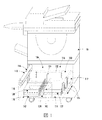
図1〜図5には、本明細書の実施形態による、同じタンデム式媒体トレイ100の種々の図が示される(これらの図では、理解を容易にするために、図中の影付き図、透視図または切り欠き図で、いくつかの特徴が示される)。図1には、開示された本明細書のシート供給装置/印刷装置10から開かれたトレイ100のほぼ全体の構造が示される。混乱を抑えるために、トレイ側面、プリンタ、供給ヘッドなどが省略されていることを除けば、図2は図1と同様である。図3および図4は図2と同様であり、トレイ内の媒体スタックの移動の様子を示す。最後に、図5は、その中に補給される全てのシートを除いた状態のトレイを示す上面図である。
FIGS. 1-5 show various views of the same tandem media tray 100 according to embodiments herein (in these views, for ease of understanding, shaded views in the drawings, Some features are shown in perspective or cutaway views). FIG. 1 shows the overall structure of a
本明細書の例示的な印刷装置および/またはシート供給装置10は、印刷エンジンと、その印刷エンジンに媒体のシートを供給するための媒体経路とを含む(詳細に関して、下記の図8を参照)。トレイ100を(取手102を用いて)移動させて、開口部104からシート供給装置/印刷装置10内に出入りさせる。これにより、ユーザは媒体のスタックをトレイ100に補給することができる。トレイ100は、例えば、エレベータ構造142と、ピッキングシステムまたは供給ヘッド140(ベルト、ニップのローラなどを含む)とを用いて、媒体のシートをシート供給装置/印刷装置10内のシート経路に供給することができる。この供給ヘッド140が、前方スタック領域内に配置される媒体のスタックからシートを抜き取る。供給ヘッド140まで前方スタックを持ち上げることができるよう、エレベータシステム142は前方スタックの真下に配置される。
The exemplary printing device and / or
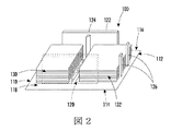
トレイ100は、トレイ前部110と、トレイ前部110の反対側に位置するトレイ後部112と、トレイ前部110とトレイ後部112の間の第1のトレイ側面114と、トレイ前部110とトレイ後部112の間で第1のトレイ側面114の反対側に位置する第2のトレイ側面116とを有し、これらの名称は任意に付けたものである。トレイフロア118は、トレイ前部110、トレイ後部112、第1のトレイ側面114、および第2のトレイ側面116に接続する。さらに、調整可能な第1の側面ガイド120は、トレイフロア118に接続する。第1の側面ガイド120は、第1のトレイ側面114と平行であり、第2のトレイ側面116よりも第1のトレイ側面114に比較的近く配置される。また、調整可能な第2の側面ガイド122もトレイフロア118と接続する。図示する通り、第2の側面ガイド122は、第1の側面ガイド120および第2のトレイ側面116と平行である。さらに、第2の側面ガイド122は、第1のトレイ側面114よりも第2のトレイ側面116に比較的近く配置される。
The
また、中間トレイセンサ124は、トレイ前部110とトレイ後部112の間の比較的に等距離に配置される。トレイの中央(媒体のスタック間)のシートの有無を検知するための位置であれば、中間トレイセンサ124をトレイ内のあらゆる面に配置可能である。例えば、図1〜図5に示す通り、中間トレイセンサ124は、第2の側面ガイド122に接続する。ある例では、この中間トレイセンサ124は突起部を含み、媒体によりこの突起部が動かされることにより、媒体の存在を検知する。あるいは、中間トレイセンサ124は、圧力センサ、光学センサ、音響センサなど、またはそれらの1つ以上のセンサの全ての組み合わせでよい。
Further, the
動力駆動式摺動板126はトレイフロア118に接続し、トレイ前部110よりもトレイ後部112に比較的近く配置される。摺動板126の移動範囲は、例えば、前方スタック領域134の中央から、トレイ後部112内またはトレイ後部112に接する、あるいは予備スタック領域136内の任意の場所までの間でよい。また、前方媒体センサ146はトレイフロア118に接続し(図3および図5に示す通り)、かつ/または、供給ヘッド140(図1および図5に示す通り)内に配置され得る。例えば、供給ヘッド内のセンサ146は、媒体がなくなると、トレイ内への下降を検知する。したがって、あらゆる位置に配置されて、トレイの前方部分の媒体を検知することができる全ての種類のセンサを示すことをアイテム146は意図する。前方媒体センサ146は、トレイ後部112よりもトレイ前部110に比較的近く配置され、前方スタック領域134内に配置される。トレイ内にその他のセンサを含み、予備スタック132の存在、側面ガイド120〜122の位置、摺動板126の位置、媒体スタックの高さなどを検知することができることは、当業者なら理解されよう。混乱を避けるためそれらのセンサは図中には示されていない。
The power driven sliding
さらに、プロセッサ60(図8)は中間トレイセンサ124、前方媒体センサ、および摺動板126に操作可能に接続する。トレイフロア118は、中間トレイセンサ124とトレイ前部110の間に前方の媒体スタック130を保持するための前方スタック領域134と、中間トレイセンサ124とトレイ後部112の間の予備の媒体スタック132を保持するための予備スタック領域136とを有する。これにより、トレイは、前方スタック領域134と予備スタック領域136の間に仕切り板を必要としない。
In addition, the processor 60 (FIG. 8) is operably connected to the
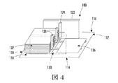
図4に示す通り、プロセッサは、前方媒体センサ146が前方スタック領域134内の媒体を検知しなくなると(図3に示す状態を参照)、摺動板126をトレイ後部112からトレイ前部110に向けて前方に移動させる。また、プロセッサは、中間トレイセンサ124が前方スタック領域134と予備スタック領域136の間に位置する媒体を検知しても、トレイ後部から112トレイ前部110に向けて前方に摺動板126を移動させる。さらに、媒体エレベータは、前方スタック領域134内のトレイフロア118に接続することができる。プロセッサは、エレベータが下部の位置に下がるまで、摺動板126の前方への移動を休止させる。
As shown in FIG. 4, the processor moves the sliding
摺動板126を前方に移動させる間、このプロセッサは、(予備スタックの先端が中間トレイセンサ124の横を通過したことを示す、中間トレイセンサ124からの入力により)、中間トレイセンサ124を通過して移動する予備の媒体スタック132を検知する。したがって、(摺動板126により、予備スタックの後端が移動中、中間トレイセンサ124の横を通過するとき)、中間トレイセンサ124が解除されると、これにより単独で、摺動板126が予備スタック132を前方スタック領域134へ適切に移動されていることが示される。あるいは、予備スタック132の前方への移動中に、中間トレイセンサ124が解除され、摺動板126を駆動させるモータ内で電流スパイクが検知され、これらが組み合わされることにより、予備スタックがトレイ前部110に完全に接していることが示される。さらに、予備スタック132を前方へ移動させる間、この摺動板126が移動中に、摺動板126を駆動させるモータ内で電流スパイクが検知されたが、中間トレイセンサ124が解除されていない場合(中間トレイセンサ124が、いまだにスタックの存在を検知している場合)、これにより、摺動板が抵抗を感じたため(電流スパイクが発生したため)ジャムが発生したことが示され、スタックが移動せず(または、移動するべき通りに、容易に移動せず)、さらに、スタックの一部が、いまだに中間トレイセンサ124に接して、押し込んでいることが示される。
While moving the sliding
したがって、本明細書の構造および方法では、予備スタック132が適切に移動できず、さらにスタックが、いまだに中間トレイセンサ124上に位置するとき、ジャムが検知される。このように中間トレイセンサ124を用いることで、端から端までの長さが同じである限り、ガイド、ゲート、またはその他の構造のあらゆる物理的調整を行うことなしに、同じ構造で自動的に全ての異なる用紙サイズに対応することができる。本明細書に関して、媒体の端から端までの長さとは、側面ガイド120と側面ガイド22の間の距離のことである。このことは、側面ガイドが移動する限り、その他の端から端までの長さに関しても有効である。本明細書の方法およびシステムでは、異なる幅の媒体スタック、予備スタック132を前方スタック領域134内に補給する前に、ガイド、ゲート、またはその他の構造の物理的調整を行う代わりに、摺動板126により発生する電流の増加、すなわちスパイクと、中間トレイセンサ124により(スタックが移動中、前もってスタックが検知された後)スタックが検知されなくなることを併せて、スタック内の用紙のサイズに関係なく、摺動板が予備スタック132を前方スタック領域134に適切に移動させたことを示す。本明細書の構造および方法では、これが行われると、ガイド、ゲート、またはその他の構造の物理的調整を行う代わりに、摺動板の位置をトレイ後部112の定位置にリセットする。さらに、摺動板の電流検知および中間トレイセンサ124が全ての媒体サイズに対応するため、摺動板のモータは、媒体サイズ関係なく、任意の正確な位置決めを必要としない。したがって、本明細書の構造および方法では、中心の仕切り板またはゲートなしに(前方ガイドから後方ガイド、ゲート、または、その他の構造の物理的調整を行うことなしに)、スタックをタンデム式トレイの極端に前方の位置、および極端に後方の位置に、ユーザが配置しなければならない方法、および単一の中間トレイセンサを用いて、全ての好適な媒体の長さに対応することができる(シートの「長さ」は、トレイ前部110とトレイ後部112の間の方向で測定される)。それでも、異なる幅の媒体に関しては、側面ガイド120、122を調整しなければならない(シート「幅」は、第1の側面114と第2の側面116の間の方向で測定される)。
Thus, in the structure and method herein, a jam is detected when the
プロセッサは、摺動板126を前方スタック領域134に移動させた後、中間トレイセンサ124が予備の媒体スタック132が前方スタック領域134内に完全に移動したことを検知すると、トレイ前部110から後方に(トレイ後部112に向けて、予備スタック領域136とトレイ後部112の間の任意の位置に)摺動板126を移動させる。
After moving the sliding
摺動板126が前方スタック領域134内に移動しても前方媒体センサが媒体を全く検知しないとき、摺動板126が予備の媒体スタック132を前方スタック領域134に完全に移動させることができないとき、摺動板126が移動しようとしても予備スタック領域136を通って後方に移動できなくなるときはいつでも、プロセッサは摺動板126を移動させながら、(可聴アラーム、および/またはユーザインターフェース上のメッセージのような表示アラームなど含む)アラームを発する。
When the sliding
本明細書の実施形態では、ユーザマニュアルディスプレイスクリーン、合図、およびラベルにより、媒体スタックをトレイ前部110に接して配置するよう、あるいは摺動板126に接して配置するよう、常にユーザに表示する。したがって、ユーザは、タンデム式トレイ100内でスタックを互いにできるだけ離して配置する。これにより、スタック間の空間が最大となり、トレイ内で媒体スタックを分離するための仕切り板を必要としない。さらに、スタック間のこのような追加的な空間により、ユーザは正確に媒体を補給し易くなる。また、このようにスタックをトレイの前方に接して、およびトレイの後方に接して配置することにより、全ての構造を前方から後方の方向(図4に示される、摺動板126が移動する方向)に調整することなく(側面ガイド120〜122を調整する可能性はあるが)、あらゆるシートサイズに対して機能する。
In the embodiments herein, the user manual display screen, cues, and labels always indicate to the user that the media stack is placed against the
図4に示す通り、もともと供給位置134内にあった媒体のスタック130を使い切った後、供給位置134には予備の媒体スタック132が自動的に押し出される。この摺動支え板126は、予備の媒体スタック132を前方スタック領域134上に押し出し、次いで、トレイ後部112に接触する(またはトレイ後部112内の)定位置に戻る。
As shown in FIG. 4, after the
一実施形態では、スタック間の空いた空間の中央に配置される単一の中間センサフラグ124を用いて、トレイ中央の媒体を検知する。図中で示す通り、センサフラグ124に完全にスタックの高さをカバーさせる代りに、小さなレバーだけにすることができる。中間トレイセンサ124は、両方のスタック間の中央に配置されているため、不注意で起動することはほとんどない。
In one embodiment, a single
この実装形態では、用紙サイズを変更するときに(例えば、A3からA4)動かさなければならない唯一の部品は、側面媒体ガイド120および122である。トレイの極端な前方および極端な後方にユーザがスタックを配置することにより、中間センサフラグ124は、確実に横方向の同じ位置まま残る。この作業は簡単であり、ラベルなどを除いて、どのように媒体のスタックを補給の仕方について多く説明するガイダンスなしで、ユーザが実行可能である。
In this implementation, the only parts that must be moved when changing the paper size (eg, A3 to A4) are the side media guides 120 and 122. By placing the stack at the extreme front and extreme rear of the tray, the
上記の通り、トレイが空になると(両方のスタックを使い切ると)、ユーザはトレイを開いて2組の1連のスタック(例えば、2つの500枚のシートのスタック)を配置する。次いで、ユーザはトレイ100を閉める。中間センサが起動しなければ、エレベータプレート142は、前方の媒体スタック130を持ち上げ始める。媒体が所定の位置に配置されるとすぐに供給ヘッド140内のセンサ146により検知され、トレイ100は媒体の供給の用意を完了する。
As described above, when the tray is empty (both stacks are used up), the user opens the tray and places two sets of stacks (eg, a stack of two 500 sheets). Next, the user closes the
媒体シートを全方に移動させているとき(および/または媒体を持ち上げているとき)、媒体検知センサ146が所定の時間内に起動しない場合、摺動支え板126(ときには、単に「摺動板」と呼ぶ)が左に移動して、予備の媒体スタック132をエレベータプレート142上に移動させる。ユーザがトレイを閉めるとき、前方スタック領域134内に媒体がない場合でも、トレイ100はこのモードになる。動いている予備の媒体スタック132の先端が、中間トレイセンサ124を通過して移動するため、摺動板126が動き始めるとすぐに、中間トレイセンサ124は起動するはずである。しかし、摺動板が前方スタック領域134に移動するとき、中間トレイセンサ124が起動しない場合、プロセッサは摺動板126をトレイ後部112に接する位置、またはトレイ後部112内の定位置に移動させる。摺動板126がその定位置に移動できない場合、アラームを発してジャムを宣言する。その一方、摺動板が定位置に到達した場合、これはトレイ内に全く媒体がないことを意味し、用紙切れ(または媒体切れ)アラームまたはメッセージを発する。
When the media sheet is moved all the way (and / or when the media is lifted), if the
予備の媒体スタック132が前方スタック領域に移動しているとき、予想通りに中間センサが起動すると、本明細書のシステムおよび方法は、摺動板を所定の時間だけ一時的に停止させて、エレベータプレート142が降りられるようにする。次いで、摺動板126は、予備の媒体スタック132の前方スタック領域134への移動を続ける。予備の媒体スタック132が前方スタック領域134内に完全に配置される(トレイ前部110に接する)直前に、予備のスタック132の後端により、中間トレイセンサ124が解除される(中間トレイセンサ124の前方の領域には、媒体シートが無いことが確認される)。このようにならない場合は、摺動板126は、前方スタック領域134に完全に移動することができず、ジャムが発生し適切なアラームが発せられる。別のケースでは、トレイの論理回路が前方スタック領域134内の供給位置に到達する媒体スタック132を探し始める。次いで、摺動板126は定位置に戻り、タンデム式トレイ100は、再度供給の用意を完了させる。
When the
別の可能性としては、ユーザがトレイを閉めると、中間トレイセンサ124が起動する(これは、ユーザが前方スタック領域134と予備スタック領域136の間にスタックを補給すると起こり得る)。この場合、摺動板126が(新しい)媒体のスタックをエレベータプレート142上に移動させるために左に移動する。摺動板126は媒体を左に移動させ、中間トレイセンサ124が起動しなくなるまで、または、時間切れになるまで、媒体の移動を続ける。中間トレイセンサ124が時間切れになった場合、トレイの論理回路は、ジャムが発生した(媒体が間違った位置にはまり、摺動板がその媒体を正しい位置に押し出すことができない状態)と判断し、上記の通り、摺動板126はその定位置に移動する。中間トレイセンサ124が起動しなくなった場合、それは、そのトレイの中央に配置された媒体が、現在は前方スタック領域134内の供給位置に移動していることを意味し、上記の通り、トレイの論理回路はその通常の処理を再開させることができる。
Another possibility is that when the user closes the tray, the
上記の処理をフローチャートの形態で図6に示す。より具体的には、図6では、この処理は、項目200で、トレイが閉められたかどうかをセンサが判定することから始まる。閉じられてない場合、項目202で、トレイが閉じられるまで待つ。項目204で、中間トレイセンサが起動したかどうかを判定する。起動しない場合、項目210で、エレベータを上昇させて、前方の媒体のスタックを供給ヘッドまで移動させる。項目212で、媒体が所定の位置に配置されたかどうかを判定し、配置されている場合、項目214で、シート供給装置または印刷装置に媒体を供給する用意が完了したことを表示する。媒体が所定の位置に配置される前に時間切れとなった場合(項目216で判定された場合)項目218で、ジャムが発生したことを表示する。そうでない場合には、項目220で、媒体切れの状態を表示する。供給ヘッド内のエレベータプレートの位置センサが、エレベータプレートが所定の位置に配置されたことを検知したが、媒体検知センサ146は媒体を全く検知しないとき、この状態が検知される。
The above processing is shown in the form of a flowchart in FIG. More specifically, in FIG. 6, the process begins at
項目204で中間トレイセンサが起動した場合、あるいは、リードスタックの位置に媒体が存在しない場合、この処理は項目230に進み、摺動板がトレイの前方に向けて移動する。項目232で、中間トレイセンサが起動するかどうかを再度判定する。起動しない場合(リードスタックが空だった場合、媒体が切れた場合、またはユーザがトレイの中央にスタックを配置した場合)、項目236で、時間切れが記録されるまで、摺動板は左へ移動し続ける。項目232で、中間トレイセンサが起動した場合、項目234で、時間を遅らせてエレベータプレートを降下させることができる。次いで、トレイの論理回路は、予備スタックを持ち上げ、次いで、供給するために、予備のスタックを所定の位置に押し出そうとする。
If the intermediate tray sensor is activated in
項目236で時間切れの場合、処理は項目240に進み、摺動板は右に(トレイの後方に)移動する。項目242で、摺動板がトレイ後部(定位置)に到達したかどうを判定する。到達してない場合、時間切れ状態が項目244まで延長され、摺動板は、トレイ後部に向かって移動し続ける。摺動板が定位置に到達すると、項目246で、摺動板の位置が定位置にリセットされ、これにより、媒体が存在していないことも表示される(そして、項目248で媒体が切れたことを示すアラームを発する)。
If
項目234で、エレベータが降下できた後、処理は項目250に進み、トレイの前方への(左への)摺動板の移動が再開される。項目252で、中間トレイセンサが起動したかどうかを確認し、項目254では、中間トレイセンサがトレイの前方に向けて動かされている間、中間トレイセンサが起動していることを確認し続ける。時間切れが項目254より延長された場合、項目256で、摺動板がトレイ内の適切な前方の位置に移動できないためジャムが発生していることを示すアラームが、この処理では発せられる。
After the elevator can be lowered at
しかし、項目252で中間トレイセンサが起動しない場合(項目250で、摺動板がトレイの前方に向かって移動しているとき)、処理は項目260に進んで、電力ピークに関する確認を行う。より具体的には、項目260で、摺動板が移動しようとしているが、あるアイテムの抵抗に合い、その引っ張る力が、移動する力を超えていることが、そのような電力ピークにより示される。項目260で、これが示された場合、項目262で、この処理では、摺動板を定位置にリセットし、次いで、項目264で、摺動板をトレイ後部に向けて移動させようとする。項目266で、摺動板がその定位置に到達しない場合(項目270で、時間切れの後、かなりの時間が経過した後)、項目272で、(摺動板がトレイの後方部分に適切に移動できないため)アラームとしてジャムの発生を宣言する。
However, if the intermediate tray sensor is not activated at item 252 (when the sliding plate is moving toward the front of the tray at item 250), the process proceeds to
項目260で、電力ピークが判定されない場合、項目280で、トレイの前方に向かう摺動板の移動(項目250での)が時間切れまで監視される。項目280で時間切れとなった場合、これにより、トレイ内でジャムが発生し、摺動板が媒体のスタックをトレイの前方に向けて移動させることができないことを表示する(そして、項目282でこの状況における適切なアラームを発する)。項目266で、摺動板が定位置に到達した場合、項目268で、摺動板の位置を定位置にリセットし、処理は項目210に戻って、エレベータを上昇可能にして、新しく補給された予備シートをシート処理装置または印刷装置に供給する。このように、上記の構造および方法では、予備スタック内に媒体あるかどうかを判定する。
If
また、このタンデム式トレイは中央に残るスタックも検知し、摺動板はスタックがエレベータプレート上の所定の位置に移動するまで左に移動する。ユーザがトレイを閉める際、媒体がトレイの中央に置かれ、中間センサを起動させてしまう要因がいくつかある。例えば、媒体を補給するとき、単にユーザが誤ってスタックを中央に置いてしまう(例えば、A3の媒体)。媒体がトレイの中央に置かれてしまう別の要因としては、スタックが移動中に装置の電源が切れてしまうケースがある。その他の可能性としては、ユーザが予備スタック上にだけスタックを補給し、トレイを再度開いてスタックの移動中に、移動する様子を確認する場合である。本明細書の構造および方法では、このような全ての場合、スタックをエレベータのプレート上に置くために、最初に摺動板をトレイの前方に移動させる。次いで、摺動板がスタックを適切に移動させた場合、供給が設定されて開始される。また、供給が開始された場合、摺動板は、次にトレイ後部の定位置の到達しようとする、しかし、開始されない場合は、ジャムのアラームが表示される。 The tandem tray also detects the stack left in the center, and the sliding plate moves to the left until the stack moves to a predetermined position on the elevator plate. When the user closes the tray, there are several factors that cause the media to be placed in the center of the tray and activate the intermediate sensor. For example, when refilling media, the user simply misplaces the stack in the center (eg, A3 media). Another factor that causes media to be placed in the center of the tray is when the device is turned off while the stack is moving. Another possibility is that the user replenishes the stack only on the spare stack, reopens the tray and checks the movement while the stack is moving. In all such cases, the structures and methods herein first move the sliding plate forward of the tray to place the stack on the elevator plate. Then, if the sliding plate has moved the stack appropriately, the supply is set and started. Also, if feeding is started, the sliding plate will next try to reach a fixed position at the rear of the tray, but if not, a jam alarm will be displayed.
このように、本明細書の構造および方法では、前方または後方への移動が終了する度に、位置をリセットするため、摺動板のモータは正確な位置合わせを行う必要はない。これは、例えば、A3からA4に媒体サイズを変更するとき、トレイの前方の壁および後方の壁に媒体のスタックを偏らせて、スタック間の隙間を変えることによる、直接的な結果である。さらに、本明細書の構造および方法では、単一の中間トレイセンサを用い、仕切り板またはゲートを削除することにより、少ない構成部品しか使用していない。さらに、本明細書の構造および方法では、トレイの中央の有効な空間を制限するガイドがないため、媒体を非常に簡単に補給することができる。これにより、中間トレイセンサの誤作動に対してより安定した設定を行うことができる。さらに、本明細書の構造および方法では、予備スタック内に媒体が補給されているかどうか、かつ、中央に媒体が残っているかどうかを素早く検知する。 Thus, in the structure and method of this specification, the position of the motor is not required to be accurately aligned because the position is reset every time the forward or backward movement is completed. This is a direct result of changing the gap between the stacks, for example, by biasing the stack of media against the front and back walls of the tray when changing the media size from A3 to A4. Further, the structure and method herein uses fewer components by using a single intermediate tray sensor and eliminating the dividers or gates. In addition, the structure and method herein can replenish media very easily because there is no guide that limits the effective space in the center of the tray. Thereby, it is possible to perform more stable setting against malfunction of the intermediate tray sensor. Furthermore, the structure and method herein quickly detects whether media is being replenished in the spare stack and whether media remains in the center.
図7には、本明細書のその他の例示的な方法を示す、簡易化した関係チャート図が示される。項目300では、前方媒体センサ146(再度記載するが、図5に示す通り、供給ヘッド、および/またはトレイフロア内に配置可能な)により検知された媒体の有無を表示する。項目302では、中間トレイ媒体センサ124により検知された媒体の有無を表示する。
FIG. 7 shows a simplified relationship chart diagram illustrating other exemplary methods herein.
この方法では、項目300で、前方媒体センサが前方スタック領域の媒体を検知しなくなると、項目304で、摺動板をトレイ後部からトレイ前部に向けて前方に移動させる。項目302で、中間トレイセンサが前方スタック領域と予備スタック領域の間に配置された媒体を検知すると(中間トレイセンサが起動すると)、項目304では、また自動的に摺動板をトレイ後部からトレイ前部に向けて前方に移動させる。項目304で、任意にエレベータが下部の位置に降下するまで、前方への摺動板の移動を中断させることができる。
In this method, when the front media sensor no longer detects media in the front stack area at
項目304で摺動板を前方に移動させている間、この例示的な方法では、中間トレイセンサ302からの入力により、中間トレイセンサを通過して移動する予備の媒体スタックを自動的に検知する。摺動板を前方スタック領域内に移動させた後、図示する通り、項目306で、予備の媒体スタックが移動して前方スタック領域に完全に置かれたことを中間トレイセンサが検知すると、この例示的な方法では、自動的にトレイ前部からトレイ後部に向けて後方に摺動板を移動させる。
While moving the sliding plate forward at
項目304で、摺動板を移動させている間、摺動板が前方スタック領域に移動し、かつ、前方媒体センサ146が媒体を検知しないと、この例示的な方法では、プロセッサを用いて、自動的にアラーム310を発する。また、項目304で、摺動板が予備の媒体スタックを前方スタック領域に完全に置くことができない場合、あるいは、摺動板が項目306で後方に移動しようとするが予備スタック領域を通って後方に移動できない場合、項目310で、(項目308により)アラームを発する。
In
Claims (20)
前記トレイ前部と前記トレイ後部の間の比較的等距離に配置される中間トレイセンサと、
前記トレイに接続する摺動板と、
前記トレイに接続し、前記トレイ後部よりも前記トレイ前部に比較的近く配置される前方媒体センサと、
前記中間トレイセンサ、前記前方媒体センサ、および前記摺動板に操作可能に接続するプロセッサと、を含み、
トレイフロアが、前方スタック領域を含んで、前記中間トレイセンサと前記トレイ前部の間に前方の媒体スタックを保持し、かつ、予備スタック領域を含んで、前記中間トレイセンサと前記トレイ後部の間に予備の媒体スタックを保持し、
前記トレイは、前記前方スタック領域と前記予備スタック領域の間に仕切り板を必要とせず、
前記プロセッサは、前記前方媒体センサが前記前方スタック領域内に媒体を検知しなくなると、前記トレイ後部から前記トレイ前部に向けて前記摺動板を前方に移動させ、
前記プロセッサは、前記中間トレイセンサが前記前方スタック領域と前記予備スタック領域の間に配置された媒体を検知すると、前記トレイ後部から前記トレイ前部に向けて前記摺動板を前方に移動させ、
前記摺動板を前記前方に移動させている間、前記プロセッサは、前記中間トレイセンサからの入力により、前記中間トレイセンサを通過して移動する前記予備の媒体スタックを検知し、
前記摺動板を前記前方スタック領域内へ移動させた後、前記プロセッサは、前記予備の媒体スタックが前記前方スタック領域内に完全に移動することを前記中間トレイセンサが検知すると、前記トレイ前部から前記トレイ後部に向けて前記摺動板を後方に移動させ、
前記摺動板を移動させている間に、
前記摺動板が前記前方スタック領域内に移動し、前記前方媒体センサが媒体を検知しない場合、
前記摺動板が前記予備の媒体スタックを、前記前方スタック領域内に完全に移動できない場合、
前記摺動板が前記予備スタック領域を通って、前記後方に移動できない場合のうちの少なくとも1つにより、前記プロセッサは、アラームを発する、シート供給装置。 A tray having a tray front, a tray rear located on the opposite side of the tray front, and a tray side surface between the tray front and the tray rear;
An intermediate tray sensor disposed at a relatively equal distance between the front of the tray and the rear of the tray;
A sliding plate connected to the tray;
A front media sensor connected to the tray and disposed relatively closer to the front of the tray than to the rear of the tray;
A processor operably connected to the intermediate tray sensor, the front media sensor, and the sliding plate;
A tray floor includes a front stack area to hold a front media stack between the intermediate tray sensor and the tray front and includes a spare stack area between the intermediate tray sensor and the rear of the tray. Keep a spare media stack in the
The tray does not require a partition plate between the front stack area and the spare stack area,
The processor moves the sliding plate forward from the rear of the tray toward the front of the tray when the front medium sensor no longer detects the medium in the front stack area,
When the intermediate tray sensor detects the medium disposed between the front stack area and the spare stack area, the processor moves the sliding plate forward from the rear of the tray toward the front of the tray,
While moving the sliding plate forward, the processor detects the spare media stack moving through the intermediate tray sensor by input from the intermediate tray sensor;
After moving the sliding plate into the front stack area, the processor detects when the intermediate tray sensor detects that the spare media stack has moved completely into the front stack area. The slide plate is moved rearward from the tray toward the rear of the tray,
While moving the sliding plate,
When the sliding plate moves into the front stack area and the front medium sensor does not detect the medium,
If the sliding plate cannot move the spare media stack completely into the front stack area,
The sheet feeding apparatus, wherein the processor issues an alarm according to at least one of the cases where the sliding plate cannot move backward through the spare stack region.
前記トレイフロアに接続し、前記第1のトレイ側面と平行で、前記第2のトレイ側面よりも前記第1のトレイ側面に比較的近く配置される第1の側面ガイドと、
前記トレイフロアに接続し、前記第2のトレイ側面と平行で、前記第1のトレイ側面よりも前記第2のトレイ側面に比較的近く配置される第2の側面ガイドと、
前記第2の側面ガイドに接続し、前記トレイ前部と前記トレイ後部の間の比較的等距離に配置される中間トレイセンサと、
前記トレイフロアに接続し、前記トレイ前部よりも前記トレイ後部に比較的近く配置される摺動板と、
前記トレイフロアに接続し、前記トレイ後部よりも前記トレイ前部に比較的近く配置される前方媒体センサと、
前記中間トレイセンサ、前記前方媒体センサ、および前記摺動板に操作可能に接続するプロセッサと、を含み、
前記トレイフロアが、前方スタック領域を含んで、前記中間トレイセンサと前記トレイ前部の間に前方の媒体スタックを保持し、かつ、予備スタック領域を含んで、前記中間トレイセンサと前記トレイ後部の間に予備の媒体スタックを保持し、
前記トレイは、前記前方スタック領域と前記予備スタック領域の間に仕切り板を必要とせず、
前記プロセッサは、前記前方媒体センサが前記前方スタック領域内に媒体を検知しなくなると、前記トレイ後部から前記トレイ前部に向けて前記摺動板を前方に移動させ、
前記プロセッサは、前記中間トレイセンサが前記前方スタック領域と前記予備スタック領域の間に配置された媒体を検知すると、前記トレイ後部から前記トレイ前部に向けて前記摺動板を前方に移動させ、
前記摺動板を前記前方に移動させている間、前記プロセッサは、前記中間トレイセンサからの入力により、前記中間トレイセンサを通過して移動する前記予備の媒体スタックを検知し、
前記摺動板を前記前方スタック領域内へ移動させた後、前記プロセッサは、前記予備の媒体スタックが前記前方スタック領域内に完全に移動することを前記中間トレイセンサが検知すると、前記トレイ前部から前記トレイ後部に向けて前記摺動板を後方に移動させ、
前記摺動板を移動させている間に、
前記摺動板が前記前方スタック領域内に移動し、前記前方媒体センサが媒体を検知しない場合、
前記摺動板が前記予備の媒体スタックを、前記前方スタック領域内に完全に移動できない場合、
前記摺動板が前記予備スタック領域を通って、前記後方に移動できない場合のうちの少なくとも1つにより、前記プロセッサは、アラームを発する、シート供給装置。 A tray front, a tray rear located on the opposite side of the tray front, a first tray side surface between the tray front and the tray rear, and the first tray between the tray front and the tray rear. A tray having a second tray side surface located on the opposite side of the side surface, and a tray floor connected to the tray front portion, the tray rear portion, the first tray side surface, and the second tray side surface;
A first side guide connected to the tray floor, parallel to the first tray side and disposed relatively closer to the first tray side than the second tray side;
A second side guide connected to the tray floor, disposed parallel to the second tray side and relatively closer to the second tray side than the first tray side;
An intermediate tray sensor connected to the second side guide and disposed at a relatively equal distance between the tray front portion and the tray rear portion;
A sliding plate connected to the tray floor and disposed relatively closer to the rear of the tray than to the front of the tray;
A front media sensor connected to the tray floor and disposed relatively closer to the front of the tray than to the rear of the tray;
A processor operably connected to the intermediate tray sensor, the front media sensor, and the sliding plate;
The tray floor includes a front stack area, holds a front media stack between the intermediate tray sensor and the tray front, and includes a spare stack area, the intermediate tray sensor and the rear of the tray. Keep a spare media stack in between,
The tray does not require a partition plate between the front stack area and the spare stack area,
The processor moves the sliding plate forward from the rear of the tray toward the front of the tray when the front medium sensor no longer detects the medium in the front stack area,
When the intermediate tray sensor detects the medium disposed between the front stack area and the spare stack area, the processor moves the sliding plate forward from the rear of the tray toward the front of the tray,
While moving the sliding plate forward, the processor detects the spare media stack moving through the intermediate tray sensor by input from the intermediate tray sensor;
After moving the sliding plate into the front stack area, the processor detects when the intermediate tray sensor detects that the spare media stack has moved completely into the front stack area. The slide plate is moved rearward from the tray toward the rear of the tray,
While moving the sliding plate,
When the sliding plate moves into the front stack area and the front medium sensor does not detect the medium,
If the sliding plate cannot move the spare media stack completely into the front stack area,
The sheet feeding apparatus, wherein the processor issues an alarm according to at least one of the cases where the sliding plate cannot move backward through the spare stack region.
媒体のシートを前記印刷エンジンに供給する媒体経路と、
前記媒体のシートを前記シート経路に供給するトレイであって、トレイ前部、前記トレイ前部の反対側に位置するトレイ後部、および前記トレイ前部と前記トレイ後部の間のトレイ側面を有するトレイと、
前記トレイ前部と前記トレイ後部の間の比較的等距離に配置される中間トレイセンサと、
前記トレイに接続する摺動板と、
前記トレイに接続し、前記トレイ後部よりも前記トレイ前部に比較的近く配置される前方媒体センサと、
前記中間トレイセンサ、前記前方媒体センサ、および前記摺動板に操作可能に接続するプロセッサと、を含み、
トレイフロアが、前方スタック領域を含んで、前記中間トレイセンサと前記トレイ前部の間に前方の媒体スタックを保持し、かつ、予備スタック領域を含んで、前記中間トレイセンサと前記トレイ後部の間に予備の媒体スタックを保持し、
前記トレイは、前記前方スタック領域と前記予備スタック領域の間に仕切り板を必要とせず、
前記プロセッサは、前記前方媒体センサが前記前方スタック領域内に媒体を検知しなくなると、前記トレイ後部から前記トレイ前部に向けて前記摺動板を前方に移動させ、
前記プロセッサは、前記中間トレイセンサが前記前方スタック領域と前記予備スタック領域の間に配置された媒体を検知すると、前記トレイ後部から前記トレイ前部に向けて前記摺動板を前方に移動させ、
前記摺動板を移動させている間、前記プロセッサは、前記中間トレイセンサからの入力により、前記中間トレイセンサを通過して移動する前記予備の媒体スタックを検知し、
前記摺動板を前記前方スタック領域内へ移動させた後、前記プロセッサは、前記予備の媒体スタックが前記前方スタック領域内に完全に移動することを前記中間トレイセンサが検知すると、前記トレイ前部から前記トレイ後部に向けて前記摺動板を後方に移動させ、
前記摺動板を移動させている間に、
前記摺動板が前記前方スタック領域内に移動し、前記前方媒体センサが媒体を検知しない場合、
前記摺動板が前記予備の媒体スタックを、前記前方スタック領域内に完全に移動できない場合、
前記摺動板が前記予備スタック領域を通って、前記後方に移動できない場合のうちの少なくとも1つにより、前記プロセッサはアラームを発する、印刷装置。 A print engine,
A media path for supplying a sheet of media to the print engine;
A tray that supplies sheets of the medium to the sheet path, the tray having a tray front portion, a tray rear portion located on the opposite side of the tray front portion, and a tray side surface between the tray front portion and the tray rear portion. When,
An intermediate tray sensor disposed at a relatively equal distance between the front of the tray and the rear of the tray;
A sliding plate connected to the tray;
A front media sensor connected to the tray and disposed relatively closer to the front of the tray than to the rear of the tray;
A processor operably connected to the intermediate tray sensor, the front media sensor, and the sliding plate;
A tray floor includes a front stack area to hold a front media stack between the intermediate tray sensor and the tray front and includes a spare stack area between the intermediate tray sensor and the rear of the tray. Keep a spare media stack in the
The tray does not require a partition plate between the front stack area and the spare stack area,
The processor moves the sliding plate forward from the rear of the tray toward the front of the tray when the front medium sensor no longer detects the medium in the front stack area,
When the intermediate tray sensor detects the medium disposed between the front stack area and the spare stack area, the processor moves the sliding plate forward from the rear of the tray toward the front of the tray,
While moving the sliding plate, the processor detects the spare media stack moving through the intermediate tray sensor in response to an input from the intermediate tray sensor;
After moving the sliding plate into the front stack area, the processor detects when the intermediate tray sensor detects that the spare media stack has moved completely into the front stack area. The slide plate is moved rearward from the tray toward the rear of the tray,
While moving the sliding plate,
When the sliding plate moves into the front stack area and the front medium sensor does not detect the medium,
If the sliding plate cannot move the spare media stack completely into the front stack area,
The printing device, wherein the processor issues an alarm upon at least one of the cases where the sliding plate cannot move back through the spare stack area.
トレイ前部、前記トレイ前部の反対側に位置するトレイ後部、および前記トレイ前部と前記トレイ後部の間のトレイ側面を有するトレイと、
前記トレイ前部と前記トレイ後部の間の比較的等距離に配置される中間トレイセンサと、
前記トレイに接続する摺動板と、
前記トレイに接続し、前記トレイ後部よりも前記トレイ前部に比較的近く配置される前方媒体センサと、
前記中間トレイセンサ、前記前方媒体センサ、および前記摺動板に操作可能に接続するプロセッサと、を含み、
トレイフロアが、前方スタック領域を含んで、前記中間トレイセンサと前記トレイ前部の間に前方の媒体スタックを保持し、かつ、予備スタック領域を含んで、前記中間トレイセンサと前記トレイ後部の間に予備の媒体スタックを保持し、
前記トレイは、前記前方スタック領域と前記予備スタック領域の間に仕切り板を必要とせず、
前記方法には、
前記前方媒体センサが前記前方スタック領域内に媒体を検知しなくなると、前記プロセッサを用いて、前記トレイ後部から前記トレイ前部に向けて前記摺動板を前方に自動的に移動させるステップと、
前記中間トレイセンサが前記前方スタック領域と前記予備スタック領域の間に配置された媒体を検知すると、前記プロセッサを用いて、前記トレイ後部から前記トレイ前部に向けて前記摺動板を前方に自動的に移動させるステップと、
前記摺動板を前記前方に移動させている間、前記プロセッサを用いて、前記中間トレイセンサからの入力により、前記中間トレイセンサを通過して移動する前記予備の媒体スタックを自動的に検知するステップと、
前記摺動板を前記前方スタック領域内へ移動させた後、前記予備の媒体スタックが前記前方スタック領域内に完全に移動することを前記中間トレイセンサが検知すると、前記プロセッサを用いて、前記トレイ前部から前記トレイ後部に向けて前記摺動板を後方に自動的に移動させるステップと、
前記摺動板を移動させている間に、
前記摺動板が前記前方スタック領域内に移動し、前記前方媒体センサが媒体を検知しない場合、
前記摺動板が前記予備の媒体スタックを、前記前方スタック領域内に完全に移動できない場合、
前記摺動板が前記予備スタック領域を通って、前記後方に移動できない場合のうちの少なくとも1つにより、前記プロセッサを用いて自動的にアラームを発するステップと、を含む方法。 A method for controlling a sheet supply apparatus, wherein the sheet supply apparatus comprises:
A tray having a tray front, a tray rear located on the opposite side of the tray front, and a tray side surface between the tray front and the tray rear;
An intermediate tray sensor disposed at a relatively equal distance between the front of the tray and the rear of the tray;
A sliding plate connected to the tray;
A front media sensor connected to the tray and disposed relatively closer to the front of the tray than to the rear of the tray;
A processor operably connected to the intermediate tray sensor, the front media sensor, and the sliding plate;
A tray floor includes a front stack area to hold a front media stack between the intermediate tray sensor and the tray front and includes a spare stack area between the intermediate tray sensor and the rear of the tray. Keep a spare media stack in the
The tray does not require a partition plate between the front stack area and the spare stack area,
The method includes:
Automatically moving the sliding plate forward from the rear of the tray toward the front of the tray using the processor when the front medium sensor no longer detects media in the front stack area;
When the intermediate tray sensor detects a medium disposed between the front stack area and the spare stack area, the sliding plate is automatically moved forward from the rear of the tray toward the front of the tray using the processor. Step to move automatically,
While the sliding plate is moved forward, the processor is used to automatically detect the spare media stack that moves past the intermediate tray sensor in response to an input from the intermediate tray sensor. Steps,
When the intermediate tray sensor detects that the spare media stack has completely moved into the front stack area after moving the sliding plate into the front stack area, the processor is used to Automatically moving the sliding plate backward from the front toward the rear of the tray;
While moving the sliding plate,
When the sliding plate moves into the front stack area and the front medium sensor does not detect the medium,
If the sliding plate cannot move the spare media stack completely into the front stack area,
Automatically issuing an alarm using the processor in accordance with at least one of the cases where the sliding plate cannot move backward through the spare stack region.
Applications Claiming Priority (2)
| Application Number | Priority Date | Filing Date | Title |
|---|---|---|---|
| US13/671,812 US8585037B1 (en) | 2012-11-08 | 2012-11-08 | Tandem media tray using mid-tray sensor |
| US13/671,812 | 2012-11-08 |
Publications (3)
| Publication Number | Publication Date |
|---|---|
| JP2014094834A JP2014094834A (en) | 2014-05-22 |
| JP2014094834A5 JP2014094834A5 (en) | 2016-12-08 |
| JP6062342B2 true JP6062342B2 (en) | 2017-01-18 |
Family
ID=49555665
Family Applications (1)
| Application Number | Title | Priority Date | Filing Date |
|---|---|---|---|
| JP2013221598A Expired - Fee Related JP6062342B2 (en) | 2012-11-08 | 2013-10-24 | Tandem media tray with intermediate tray sensor |
Country Status (2)
| Country | Link |
|---|---|
| US (1) | US8585037B1 (en) |
| JP (1) | JP6062342B2 (en) |
Families Citing this family (9)
| Publication number | Priority date | Publication date | Assignee | Title |
|---|---|---|---|---|
| JP6146393B2 (en) * | 2014-11-13 | 2017-06-14 | コニカミノルタ株式会社 | Paper feeding device and image forming apparatus |
| JP2017052597A (en) * | 2015-09-08 | 2017-03-16 | キヤノン株式会社 | Sheet feeding device and image formation apparatus |
| JP6600200B2 (en) * | 2015-09-08 | 2019-10-30 | キヤノン株式会社 | Image forming apparatus |
| JP6632273B2 (en) * | 2015-09-08 | 2020-01-22 | キヤノン株式会社 | Paper feeding apparatus, image forming apparatus, and control method for image forming apparatus |
| CN105523422B (en) * | 2016-01-13 | 2017-10-31 | 浙江茉织华印刷股份有限公司 | A kind of assembling machine |
| US20190009581A1 (en) * | 2016-04-29 | 2019-01-10 | Hewlett-Packard Development Company, L.P | Printer |
| US10577204B2 (en) * | 2017-08-31 | 2020-03-03 | Canon Finetech Nisca Inc. | Stacking apparatus, feeding apparatus, and image forming apparatus |
| CN110722836B (en) * | 2019-11-06 | 2021-11-05 | 安徽百盛源包装材料有限公司 | Conveying and arranging device for cut packaging bags |
| JP7465449B2 (en) | 2020-06-29 | 2024-04-11 | 大日本印刷株式会社 | Card supply device and card printer |
Family Cites Families (17)
| Publication number | Priority date | Publication date | Assignee | Title |
|---|---|---|---|---|
| JP2938583B2 (en) * | 1989-12-22 | 1999-08-23 | 株式会社リコー | Paper feeder |
| US5669057A (en) | 1995-10-03 | 1997-09-16 | Xerox Corporation | Reproduction machine having a tandem automatic document handler |
| JP3314329B2 (en) * | 1996-04-25 | 2002-08-12 | ミノルタ株式会社 | Automatic paper feeder |
| JP3957885B2 (en) | 1997-12-26 | 2007-08-15 | 東北リコー株式会社 | Paper feeder |
| US6032004A (en) | 1998-01-08 | 2000-02-29 | Xerox Corporation | Integral safety interlock latch mechanism |
| JP2000168968A (en) | 1998-12-03 | 2000-06-20 | Ricoh Co Ltd | Paper sheet feeder |
| US6332609B1 (en) * | 2000-02-18 | 2001-12-25 | Toshiba Tec Kabushiki Kaisha | Feed paper apparatus and image forming apparatus |
| JP4689073B2 (en) | 2001-05-14 | 2011-05-25 | 東北リコー株式会社 | Paper discharge device and image forming apparatus |
| JP4410434B2 (en) | 2001-05-16 | 2010-02-03 | 東北リコー株式会社 | Paper feeder and image forming device |
| KR100806864B1 (en) * | 2005-07-12 | 2008-02-22 | 삼성전자주식회사 | paper-feeding apparatus of image forming device and paper-feeding method thereof |
| US7866654B2 (en) | 2007-09-13 | 2011-01-11 | Kabushiki Kaisha Toshiba | Sheet conveying apparatus |
| US7654514B2 (en) | 2007-11-20 | 2010-02-02 | Xerox Corporation | High capacity tandem stack shuttle feeder module |
| US7823869B2 (en) * | 2007-12-10 | 2010-11-02 | Kabushiki Kaisha Toshiba | Sheet feeder, image forming apparatus having the same, and method for sheet feeding |
| US7874664B2 (en) | 2008-07-23 | 2011-01-25 | Xerox Corporation | Electrically conductive pressure roll surfaces for phase-change ink-jet printer for direct on paper printing |
| KR101523983B1 (en) * | 2008-10-14 | 2015-05-29 | 삼성전자 주식회사 | Paper supply unit |
| JP2010149947A (en) | 2008-12-24 | 2010-07-08 | Ricoh Co Ltd | Locking device of paper feed tray and image forming apparatus |
| KR101749568B1 (en) * | 2010-09-27 | 2017-07-03 | 에스프린팅솔루션 주식회사 | Paper supply unit and control method thereof and image forming apparatus for the same |
-
2012
- 2012-11-08 US US13/671,812 patent/US8585037B1/en not_active Expired - Fee Related
-
2013
- 2013-10-24 JP JP2013221598A patent/JP6062342B2/en not_active Expired - Fee Related
Also Published As
| Publication number | Publication date |
|---|---|
| JP2014094834A (en) | 2014-05-22 |
| US8585037B1 (en) | 2013-11-19 |
Similar Documents
| Publication | Publication Date | Title |
|---|---|---|
| JP6062342B2 (en) | Tandem media tray with intermediate tray sensor | |
| US8342501B2 (en) | Sheet feeding device and image forming apparatus with a plurality of sheet feed trays | |
| US7140796B2 (en) | Recording apparatus | |
| EP2065321A2 (en) | Measuring device, sheet-shaped material transporting device, image formation device and measuring method | |
| JP2013184765A (en) | Sheet discharge device and image forming apparatus using the same | |
| US9751339B2 (en) | Anti-jamming device for printing apparatuses with stacker | |
| JP7142896B2 (en) | Ticket issuing device | |
| JP2020152549A (en) | Switch opening/closing detection device | |
| JP3441475B2 (en) | Paper feeder | |
| JP6182416B2 (en) | Paper feeding device and paper feeding method | |
| US8567940B2 (en) | Medium feed device and recording apparatus | |
| JP2014210624A (en) | Sheet ejection device | |
| KR20120067956A (en) | Conveying device and printer | |
| KR20180053380A (en) | Media laminator | |
| US7611143B2 (en) | Sheet separating apparatus and method | |
| JP2019202870A (en) | Image formation device | |
| US11623459B2 (en) | Recording apparatus and medium housing apparatus | |
| JP2017109364A (en) | Control method for printer and printer | |
| JP2005349832A (en) | Image formation device | |
| JPS6143788Y2 (en) | ||
| JP2012250804A (en) | Paper holding device | |
| KR100985480B1 (en) | Printed document feeding apparatus for self-service verification issue machine | |
| JPH0225789Y2 (en) | ||
| JP2011104917A (en) | Recording apparatus | |
| JP2009091074A (en) | Sheet feeder |
Legal Events
| Date | Code | Title | Description |
|---|---|---|---|
| RD04 | Notification of resignation of power of attorney |
Free format text: JAPANESE INTERMEDIATE CODE: A7424 Effective date: 20140418 |
|
| A521 | Request for written amendment filed |
Free format text: JAPANESE INTERMEDIATE CODE: A523 Effective date: 20161021 |
|
| A621 | Written request for application examination |
Free format text: JAPANESE INTERMEDIATE CODE: A621 Effective date: 20161021 |
|
| A871 | Explanation of circumstances concerning accelerated examination |
Free format text: JAPANESE INTERMEDIATE CODE: A871 Effective date: 20161021 |
|
| A975 | Report on accelerated examination |
Free format text: JAPANESE INTERMEDIATE CODE: A971005 Effective date: 20161122 |
|
| TRDD | Decision of grant or rejection written | ||
| A01 | Written decision to grant a patent or to grant a registration (utility model) |
Free format text: JAPANESE INTERMEDIATE CODE: A01 Effective date: 20161129 |
|
| A61 | First payment of annual fees (during grant procedure) |
Free format text: JAPANESE INTERMEDIATE CODE: A61 Effective date: 20161214 |
|
| R150 | Certificate of patent or registration of utility model |
Ref document number: 6062342 Country of ref document: JP Free format text: JAPANESE INTERMEDIATE CODE: R150 |
|
| R250 | Receipt of annual fees |
Free format text: JAPANESE INTERMEDIATE CODE: R250 |
|
| R250 | Receipt of annual fees |
Free format text: JAPANESE INTERMEDIATE CODE: R250 |
|
| LAPS | Cancellation because of no payment of annual fees |