JP6056275B2 - Liquid ejecting head maintenance method and liquid ejecting apparatus - Google Patents
Liquid ejecting head maintenance method and liquid ejecting apparatus Download PDFInfo
- Publication number
- JP6056275B2 JP6056275B2 JP2012189629A JP2012189629A JP6056275B2 JP 6056275 B2 JP6056275 B2 JP 6056275B2 JP 2012189629 A JP2012189629 A JP 2012189629A JP 2012189629 A JP2012189629 A JP 2012189629A JP 6056275 B2 JP6056275 B2 JP 6056275B2
- Authority
- JP
- Japan
- Prior art keywords
- liquid
- liquid ejecting
- head
- holding member
- cover
- Prior art date
- Legal status (The legal status is an assumption and is not a legal conclusion. Google has not performed a legal analysis and makes no representation as to the accuracy of the status listed.)
- Active
Links
Images


Description
本発明は、液体を噴射する液体噴射ヘッドのメンテナンス方法及び液体噴射装置に関する。 The present invention relates to a maintenance method and a liquid ejecting apparatus for a liquid ejecting head that ejects a liquid.
被噴射媒体に液体を噴射する液体噴射装置には、例えば、液体としてインクを噴射させて紙や記録シートなどの被記録媒体(被噴射媒体)に印刷を行うインクジェット式記録装置が知られている。 As a liquid ejecting apparatus that ejects liquid onto an ejected medium, for example, an ink jet recording apparatus that performs printing on a recording medium (ejecting medium) such as paper or a recording sheet by ejecting ink as a liquid is known. .
このようなインクジェット式記録装置に搭載されるインクジェット式記録ヘッドは、ノズル開口からインク滴を被噴射媒体上に吐出しているため、インク滴を噴射する液体噴射面のノズル開口近傍にインクが付着することにより、また、付着したインクが固化することにより、例えば、インク滴の吐出方向が安定しないという問題や、インク滴が吐出されないなどの吐出不良が発生するという問題がある。 An ink jet recording head mounted on such an ink jet recording apparatus ejects ink droplets from a nozzle opening onto a medium to be ejected, so that ink adheres to the vicinity of the nozzle opening of a liquid ejecting surface that ejects the ink droplet. By doing so, there is a problem that, for example, the adhered ink is solidified, the ejection direction of the ink droplets is not stable, and the ejection failure such that the ink droplets are not ejected occurs.
このため、ゴム板等のワイピングブレードを液体噴射面に摺接させることにより、液体噴射面に付着したインクや毛羽、ホコリ、紙粉等をクリーニングする液体噴射装置が提案されている(例えば、特許文献1参照)。 For this reason, a liquid ejecting apparatus that cleans ink, fluff, dust, paper dust, and the like adhering to the liquid ejecting surface by sliding a wiping blade such as a rubber plate on the liquid ejecting surface has been proposed (for example, patents). Reference 1).
また、液体噴射面をワイピングブレードでワイピングしたとしても、液体噴射面の端部を覆うカバーヘッドの表面にインクや毛羽、ホコリ、紙粉等が付着し、カバープレートに被噴射媒体等が接触した際に被噴射媒体を汚してしまうという問題がある。 In addition, even when the liquid ejection surface is wiped with a wiping blade, ink, fluff, dust, paper dust, etc. adhere to the surface of the cover head that covers the end of the liquid ejection surface, and the ejected medium or the like comes into contact with the cover plate. There is a problem that the medium to be ejected is contaminated.
また、カバーヘッドの表面の汚れを手動で拭き取ろうとすると、狭いスペースでの作業になるため煩雑であり、誤って液体噴射面を傷付けることや破損させる虞があった。 In addition, if it is attempted to wipe off the dirt on the surface of the cover head manually, the operation is performed in a narrow space, which is cumbersome, and there is a risk that the liquid ejection surface may be damaged or damaged by mistake.
さらに、吐出されるインク滴を帯電させて、帯電させたインク滴を所定の場所に着弾させて、着弾位置における電圧変化を測定することで、インク滴の吐出不良を測定する場合、カバーヘッドの表面に付着したホコリや毛羽等がアンテナとして機能し、電圧変化を正確に測定することができずにインク滴の吐出不良の測定精度が低下してしまうという問題がある。 Furthermore, when measuring the ink droplet ejection failure by charging the ejected ink droplet, landing the charged ink droplet at a predetermined location, and measuring the voltage change at the landing position, There is a problem that dust, fluff, etc. attached to the surface function as an antenna, and the change in voltage cannot be measured accurately, and the measurement accuracy of ink droplet ejection failure is reduced.
このため、特許文献1等では、ワイピングブレードと共に移動する剛性材料からなるスクレーパーを設け、スクレーパーをカバーヘッドの表面に摺接させることで、カバーヘッドの表面をクリーニングするようにしている。
For this reason, in
しかしながら、特許文献1のように、剛性材料からなるスクレーパーを用いると、カバーヘッドの表面、すなわち被噴射媒体に相対向する面のクリーニングは行えるものの、スクレーパーは異物をカバーヘッドの表面から押し退けるため、押し退けられた異物が側面に移動し、側面に付着した異物によって、被噴射媒体が汚れてしまうという問題や、異物がアンテナとして機能して、インク滴の吐出不良の測定を高精度に行えないという問題があった。
However, as in
また、スクレーパーに代わって不織布等の布を設けることも考えられるものの、装置内に布を載置しておくだけで、布はインクを吸水してしまい、布によってカバーヘッドの表面を拭き取ることで、逆にカバーヘッドの表面が汚れてしまうことがあるという問題がある。 Although it is possible to provide a cloth such as a non-woven fabric in place of the scraper, the cloth absorbs ink just by placing the cloth in the apparatus, and the surface of the cover head is wiped off by the cloth. Conversely, there is a problem that the surface of the cover head may become dirty.
なお、このような問題はインクジェット式記録ヘッドユニットだけではなく、インク以外の液体を噴射する液体噴射ヘッドユニットにおいても同様に存在する。 Such a problem exists not only in the ink jet recording head unit but also in a liquid ejecting head unit that ejects liquid other than ink.
本発明はこのような事情に鑑み、カバーヘッドの清掃を容易に且つ確実に行って、被噴射媒体の汚れや液体噴射面の破損を抑制した液体噴射ヘッドのメンテナンス方法及び液体噴射装置を提供することを目的とする。 In view of such circumstances, the present invention provides a liquid ejecting head maintenance method and a liquid ejecting apparatus in which cleaning of a cover head is performed easily and surely to suppress contamination of a medium to be ejected and damage to a liquid ejecting surface. For the purpose.
[適用例1]
上記課題を解決する本発明の適用例は、液体を噴射するノズル開口が開口する液体噴射面と、該液体噴射面上に設けられて当該液体噴射面を前記ノズル開口を露出させた状態で覆うカバーヘッドと、を具備する液体噴射ヘッドのメンテナンス方法であって、前記液体噴射面に摺接可能に設けられて弾性部材からなる第1部材を保持すると共に、前記液体噴射面の面方向に移動可能に設けられた保持部材に、液体吸収材からなる第2部材を着脱可能に保持させて、前記保持部材を前記液体噴射面の面方向に移動させることで、前記第2部材を前記カバーヘッドに摺接させて、当該第2部材で前記カバーヘッドをワイピングし、前記第1部材が前記保持部材に着脱可能に保持されていると共に、前記第2部材は、前記第1部材と交換することで当該第2部材を前記保持部材に保持させることを特徴とする液体噴射ヘッドのメンテナンス方法にある。
かかる適用例では、液体吸収材からなる第2部材を用いることで、カバーヘッドに付着した液体やホコリ、毛羽、紙粉などの異物を第2部材で絡め取ることができる。したがって、カバーヘッドに液体や異物が付着することによる不具合を抑制することができる。また、液体吸収材からなる第2部材を保持部材に着脱可能とすることで、使用しないときには第2部材を取り外すことができる。したがって、第2部材に液体や異物が吸着して、液体や異物が吸着した第2部材でカバーヘッドをワイピングすることでカバーヘッドが汚れるのを抑制することができる。また、第1部材と第2部材とを交換することで、第1部材を保持した保持部材で第2部材を移動させることができ、第2部材を移動させる専用の保持部材が不要となる。
[適用例2]
上記課題を解決する本発明の他の適用例は、液体を噴射するノズル開口が開口する液体噴射面と、該液体噴射面上に設けられて当該液体噴射面を前記ノズル開口を露出させた状態で覆うカバーヘッドと、を具備する液体噴射ヘッドのメンテナンス方法であって、前記液体噴射面に摺接可能に設けられて弾性部材からなる第1部材を保持すると共に、前記液体噴射面の面方向に移動可能に設けられた保持部材に、液体吸収材からなる第2部材を着脱可能に保持させて、前記保持部材を前記液体噴射面の面方向に移動させることで、前記第2部材を前記カバーヘッドに摺接させて、当該第2部材で前記カバーヘッドをワイピングし、前記液体噴射ヘッドが複数設けられており、前記第2部材が複数の前記液体噴射ヘッドの前記カバーヘッドに同時に摺接する長さで設けられていることを特徴とする液体噴射ヘッドのメンテナンス方法にある。
かかる適用例では、液体吸収材からなる第2部材を用いることで、カバーヘッドに付着した液体やホコリ、毛羽、紙粉などの異物を第2部材で絡め取ることができる。したがって、カバーヘッドに液体や異物が付着することによる不具合を抑制することができる。また、液体吸収材からなる第2部材を保持部材に着脱可能とすることで、使用しないときには第2部材を取り外すことができる。したがって、第2部材に液体や異物が吸着して、液体や異物が吸着した第2部材でカバーヘッドをワイピングすることでカバーヘッドが汚れるのを抑制することができる。また、保持部材を移動させる回数を低減して、短時間でメンテナンスを行うことができる。
[適用例3]
上記課題を解決する本発明の他の適用例は、液体を噴射するノズル開口が開口する液体噴射面と、該液体噴射面上に設けられて当該液体噴射面を前記ノズル開口を露出させた状態で覆うカバーヘッドと、を具備する液体噴射ヘッドのメンテナンス方法であって、前記液体噴射面に摺接可能に設けられて弾性部材からなる第1部材を保持すると共に、前記液体噴射面の面方向に移動可能に設けられた保持部材に、液体吸収材からなる第2部材を着脱可能に保持させて、前記保持部材を前記液体噴射面の面方向に移動させることで、前記第2部材を前記カバーヘッドに摺接させて、当該第2部材で前記カバーヘッドをワイピングし、前記第1部材を用いたクリーニングを、印刷時に行い、前記第2部材を用いたクリーニングを、印刷時に行わないことを特徴とする液体噴射ヘッドのメンテナンス方法にある。
かかる適用例では、液体吸収材からなる第2部材を用いることで、カバーヘッドに付着した液体やホコリ、毛羽、紙粉などの異物を第2部材で絡め取ることができる。したがって、カバーヘッドに液体や異物が付着することによる不具合を抑制することができる。また、液体吸収材からなる第2部材を保持部材に着脱可能とすることで、使用しないときには第2部材を取り外すことができる。したがって、第2部材に液体や異物が吸着して、液体や異物が吸着した第2部材でカバーヘッドをワイピングすることでカバーヘッドが汚れるのを抑制することができる。また、第2部材を常に保持部材に保持させておかなくてもよくなる。よって、ミストとなったインクが第2部材に吸水されたり、ホコリや毛羽、紙粉などの異物が第2部材に吸着されたりすることを低減することができる。
[適用例4]
ここで、前記第1部材が前記保持部材に着脱可能に保持されていると共に、前記第2部材は、前記第1部材と交換することで当該第2部材を前記保持部材に保持させることが好ましい。
これによれば、第1部材と第2部材とを交換することで、第1部材を保持した保持部材で第2部材を移動させることができ、第2部材を移動させる専用の保持部材が不要となる。
[適用例5]
ここで、前記液体噴射ヘッドが複数設けられており、前記第2部材が複数の前記液体噴射ヘッドの前記カバーヘッドに同時に摺接する長さで設けられていることが好ましい。
これによれば、保持部材を移動させる回数を低減して、短時間でメンテナンスを行うことができる。
[適用例6]
ここで、前記カバーヘッドのワイピングは、前記第2部材に液体洗浄用の界面活性剤を含む洗浄液を染み込ませて行うことが好ましい。
これによれば、カバーヘッドに付着して固化した液体や異物などを比較的容易に除去することができる。
[適用例7]
ここで、前記第1部材を用いたクリーニングを、印刷時に行い、前記第2部材を用いたクリーニングを、印刷時に行わないことが好ましい。
これによれば、第2部材を常に保持部材に保持させておかなくてもよくなる。よって、ミストとなったインクが第2部材に吸水されたり、ホコリや毛羽、紙粉などの異物が第2部材に吸着されたりすることを低減することができる。
[適用例8]
上記課題を解決する本発明の他の適用例は、液体を噴射するノズル開口が開口する液体噴射面及び該液体噴射面上に設けられて当該液体噴射面を前記ノズル開口を露出させた状態で覆うカバーヘッドを具備する液体噴射ヘッドと、前記液体噴射ヘッドの前記液体噴射面の面方向に移動可能に設けられた保持部材と、該保持部材に保持されて、前記液体噴射面に摺接する弾性部材からなる第1部材と、前記保持部材に着脱可能に保持されて、前記カバーヘッドに摺接する液体吸収材からなる第2部材と、を具備し、前記第1部材は、前記保持部材に着脱可能に保持され、前記第2部材は、前記第1部材と交換されることにより前記保持部材に保持されることを特徴とする液体噴射装置にある。
[適用例9]
上記課題を解決する本発明の他の適用例は、液体を噴射するノズル開口が開口する液体噴射面及び該液体噴射面上に設けられて当該液体噴射面を前記ノズル開口を露出させた状態で覆うカバーヘッドを具備する液体噴射ヘッドと、前記液体噴射ヘッドの前記液体噴射面の面方向に移動可能に設けられた保持部材と、該保持部材に保持されて、前記液体噴射面に摺接する弾性部材からなる第1部材と、前記保持部材に着脱可能に保持されて、前記カバーヘッドに摺接する液体吸収材からなる第2部材と、を具備し、前記液体噴射ヘッドは、複数設けられており、前記第2部材は、複数の前記液体噴射ヘッドの前記カバーヘッドに同時に摺接する長さで設けられていることを特徴とする液体噴射装置にある。
[適用例10]
上記課題を解決する本発明の他の適用例は、液体を噴射するノズル開口が開口する液体噴射面及び該液体噴射面上に設けられて当該液体噴射面を前記ノズル開口を露出させた状態で覆うカバーヘッドを具備する液体噴射ヘッドと、前記液体噴射ヘッドの前記液体噴射面の面方向に移動可能に設けられた保持部材と、該保持部材に保持されて、前記液体噴射面に摺接する弾性部材からなる第1部材と、前記保持部材に着脱可能に保持されて、前記カバーヘッドに摺接する液体吸収材からなる第2部材と、を具備し、前記第1部材が前記保持部材に保持された状態で印刷を行い、前記第2部材が前記保持部材に保持された状態で印刷を行わないことを特徴とする液体噴射装置にある。
あるいは、上記課題を解決する本発明の他の態様は、液体を噴射するノズル開口が開口する液体噴射面と、該液体噴射面上に設けられて当該液体噴射面を前記ノズル開口を露出させた状態で覆うカバーヘッドと、を具備する液体噴射ヘッドのメンテナンス方法であって、前記液体噴射面に摺接可能に設けられて弾性部材からなる第1部材を保持すると共に、前記液体噴射面の面方向に移動可能に設けられた保持部材に、液体吸収材からなる第2部材を着脱可能に保持させて、前記保持部材を前記液体噴射面の面方向に移動させることで、前記第2部材を前記カバーヘッドに摺接させて、当該第2部材で前記カバーヘッドをワイピングすることを特徴とする液体噴射ヘッドのメンテナンス方法にある。
かかる態様では、液体吸収材からなる第2部材を用いることで、カバーヘッドに付着した液体やホコリ、毛羽、紙粉などの異物を第2部材で絡め取ることができる。したがって、カバーヘッドに液体や異物が付着することによる不具合を抑制することができる。また、液体吸収材からなる第2部材を保持部材に着脱可能とすることで、使用しないときには第2部材を取り外すことができる。したがって、第2部材に液体や異物が吸着して、液体や異物が吸着した第2部材でカバーヘッドをワイピングすることでカバーヘッドが汚れるのを抑制することができる。
[Application Example 1]
An application example of the present invention that solves the above problem includes a liquid ejecting surface in which a nozzle opening for ejecting liquid is opened, and the liquid ejecting surface that is provided on the liquid ejecting surface and covers the liquid ejecting surface with the nozzle opening exposed. A liquid ejecting head maintenance method comprising: a cover head; and holding a first member made of an elastic member so as to be slidable on the liquid ejecting surface and moving in a surface direction of the liquid ejecting surface A second member made of a liquid absorbent material is detachably held by a holding member provided in a removable manner, and the holding member is moved in the surface direction of the liquid ejecting surface, whereby the second member is moved to the cover head. The cover head is wiped by the second member, the first member is detachably held by the holding member, and the second member is replaced with the first member. In In maintenance method for a liquid jet head, characterized in that to hold the second member to the holding member.
In this application example, by using the second member made of the liquid absorbent material, foreign matters such as liquid, dust, fluff, and paper dust attached to the cover head can be entangled by the second member. Therefore, it is possible to suppress problems caused by liquid or foreign matter adhering to the cover head. In addition, by making the second member made of the liquid absorbent material detachable from the holding member, the second member can be removed when not in use. Therefore, it is possible to prevent the cover head from being stained by wiping the cover head with the second member having the liquid or foreign matter adsorbed on the second member and adsorbing the liquid or foreign matter. In addition, by exchanging the first member and the second member, the second member can be moved by the holding member holding the first member, and a dedicated holding member for moving the second member becomes unnecessary.
[Application Example 2]
Another application example of the present invention that solves the above problems is a state in which a nozzle opening for ejecting liquid is opened, and a state in which the nozzle opening is exposed on the liquid ejection surface provided on the liquid ejection surface A liquid ejecting head maintenance method comprising: a cover head covered with a liquid ejecting head, wherein the liquid ejecting head has a first member made of an elastic member provided so as to be slidable on the liquid ejecting surface, and a surface direction of the liquid ejecting surface The second member made of a liquid absorbent material is detachably held by a holding member provided so as to be movable, and the holding member is moved in the surface direction of the liquid ejecting surface, whereby the second member is A plurality of liquid ejecting heads are provided by slidably contacting a cover head and wiping the cover head with the second member, and the second member is simultaneously provided with the cover heads of the plurality of liquid ejecting heads. In maintenance method for a liquid jet head, characterized in that provided in the sliding contact length.
In this application example, by using the second member made of the liquid absorbent material, foreign matters such as liquid, dust, fluff, and paper dust attached to the cover head can be entangled by the second member. Therefore, it is possible to suppress problems caused by liquid or foreign matter adhering to the cover head. In addition, by making the second member made of the liquid absorbent material detachable from the holding member, the second member can be removed when not in use. Therefore, it is possible to prevent the cover head from being stained by wiping the cover head with the second member having the liquid or foreign matter adsorbed on the second member and adsorbing the liquid or foreign matter. Further, the number of times of moving the holding member can be reduced and maintenance can be performed in a short time.
[Application Example 3]
Another application example of the present invention that solves the above problems is a state in which a nozzle opening for ejecting liquid is opened, and a state in which the nozzle opening is exposed on the liquid ejection surface provided on the liquid ejection surface A liquid ejecting head maintenance method comprising: a cover head covered with a liquid ejecting head, wherein the liquid ejecting head has a first member made of an elastic member provided so as to be slidable on the liquid ejecting surface, and a surface direction of the liquid ejecting surface The second member made of a liquid absorbent material is detachably held by a holding member provided so as to be movable, and the holding member is moved in the surface direction of the liquid ejecting surface, whereby the second member is The cover head is slid in contact with the cover member, and the cover member is wiped with the second member. Cleaning using the first member is performed during printing, and cleaning using the second member is not performed during printing. Doo is in maintenance method for a liquid jet head according to claim.
In this application example, by using the second member made of the liquid absorbent material, foreign matters such as liquid, dust, fluff, and paper dust attached to the cover head can be entangled by the second member. Therefore, it is possible to suppress problems caused by liquid or foreign matter adhering to the cover head. In addition, by making the second member made of the liquid absorbent material detachable from the holding member, the second member can be removed when not in use. Therefore, it is possible to prevent the cover head from being stained by wiping the cover head with the second member having the liquid or foreign matter adsorbed on the second member and adsorbing the liquid or foreign matter. Also, the second member need not always be held by the holding member. Therefore, it is possible to reduce the fact that ink that has become mist is absorbed by the second member, and foreign matters such as dust, fluff, and paper dust are adsorbed by the second member.
[Application Example 4]
Here, it is preferable that the first member is detachably held by the holding member, and the second member is replaced with the first member to hold the second member on the holding member. .
According to this, by exchanging the first member and the second member, the second member can be moved by the holding member holding the first member, and a dedicated holding member for moving the second member is unnecessary. It becomes.
[Application Example 5]
Here, it is preferable that a plurality of the liquid ejecting heads are provided, and the second member is provided with a length that is in sliding contact with the cover heads of the plurality of liquid ejecting heads simultaneously.
According to this, the frequency | count of moving a holding member can be reduced and a maintenance can be performed in a short time.
[Application Example 6]
Here, it is preferable that the wiping of the cover head is performed by impregnating the second member with a cleaning liquid containing a liquid cleaning surfactant.
According to this, it is possible to relatively easily remove liquid, foreign matter, and the like that have adhered to the cover head and solidified.
[Application Example 7]
Here, it is preferable that the cleaning using the first member is performed during printing, and the cleaning using the second member is not performed during printing.
According to this, the second member need not always be held by the holding member. Therefore, it is possible to reduce the fact that ink that has become mist is absorbed by the second member, and foreign matters such as dust, fluff, and paper dust are adsorbed by the second member.
[Application Example 8]
In another application example of the present invention that solves the above-described problem, a liquid ejection surface that is provided with a nozzle opening that ejects liquid and the liquid ejection surface that is provided on the liquid ejection surface are exposed. A liquid ejecting head including a covering head; a holding member provided to be movable in a surface direction of the liquid ejecting surface of the liquid ejecting head; and an elastic member that is held by the holding member and is in sliding contact with the liquid ejecting surface. A first member made of a member, and a second member made of a liquid absorbing material that is detachably held by the holding member and is in sliding contact with the cover head, and the first member is attached to and detached from the holding member. The liquid ejecting apparatus is characterized in that the second member is held by the holding member by being exchanged with the first member.
[Application Example 9]
In another application example of the present invention that solves the above-described problem, a liquid ejection surface that is provided with a nozzle opening that ejects liquid and the liquid ejection surface that is provided on the liquid ejection surface are exposed. A liquid ejecting head including a covering head; a holding member provided to be movable in a surface direction of the liquid ejecting surface of the liquid ejecting head; and an elastic member that is held by the holding member and is in sliding contact with the liquid ejecting surface. A first member made of a member, and a second member made of a liquid absorbing material that is detachably held by the holding member and is in sliding contact with the cover head, and a plurality of the liquid ejecting heads are provided. In the liquid ejecting apparatus, the second member is provided with a length that is in sliding contact with the cover heads of the plurality of liquid ejecting heads at the same time.
[Application Example 10]
In another application example of the present invention that solves the above-described problem, a liquid ejection surface that is provided with a nozzle opening that ejects liquid and the liquid ejection surface that is provided on the liquid ejection surface are exposed. A liquid ejecting head including a covering head; a holding member provided to be movable in a surface direction of the liquid ejecting surface of the liquid ejecting head; and an elastic member that is held by the holding member and is in sliding contact with the liquid ejecting surface. A first member made of a member, and a second member made of a liquid absorbing material that is detachably held by the holding member and is in sliding contact with the cover head, and the first member is held by the holding member. In the liquid ejecting apparatus, printing is performed in a state where the second member is held and the second member is held by the holding member, and printing is not performed.
Alternatively, according to another aspect of the present invention for solving the above-described problem, a liquid ejecting surface in which a nozzle opening for ejecting liquid is opened and the nozzle opening is exposed on the liquid ejecting surface provided on the liquid ejecting surface. A liquid ejecting head maintenance method comprising: a cover head that covers the liquid ejecting surface; and a first member made of an elastic member that is slidably contacted with the liquid ejecting surface. The holding member provided movably in the direction is detachably held by the second member made of the liquid absorbing material, and the holding member is moved in the surface direction of the liquid ejecting surface, thereby moving the second member. In the maintenance method of the liquid jet head, the cover head is wiped by the second member while being brought into sliding contact with the cover head.
In such an aspect, by using the second member made of the liquid absorbent material, foreign matters such as liquid, dust, fluff, and paper dust attached to the cover head can be entangled by the second member. Therefore, it is possible to suppress problems caused by liquid or foreign matter adhering to the cover head. In addition, by making the second member made of the liquid absorbent material detachable from the holding member, the second member can be removed when not in use. Therefore, it is possible to prevent the cover head from being stained by wiping the cover head with the second member having the liquid or foreign matter adsorbed on the second member and adsorbing the liquid or foreign matter.
ここで、前記第1部材が前記保持部材に着脱可能に保持されていると共に、前記第2部材は、前記第1部材と交換することで当該第2部材を前記保持部材に保持させることが好ましい。これによれば、第1部材と第2部材とを交換することで、第1部材を保持した保持部材で第2部材を移動させることができ、第2部材を移動させる専用の保持部材が不要となる。 Here, it is preferable that the first member is detachably held by the holding member, and the second member is replaced with the first member to hold the second member on the holding member. . According to this, by exchanging the first member and the second member, the second member can be moved by the holding member holding the first member, and a dedicated holding member for moving the second member is unnecessary. It becomes.
また、前記液体噴射ヘッドが複数設けられており、前記第2部材が複数の前記液体噴射ヘッドの前記カバーヘッドに同時に摺接する長さで設けられていることが好ましい。これによれば、保持部材を移動させる回数を低減して、短時間でメンテナンスを行うことができる。 In addition, it is preferable that a plurality of the liquid ejecting heads are provided, and the second member is provided so as to be in sliding contact with the cover heads of the plurality of liquid ejecting heads simultaneously. According to this, the frequency | count of moving a holding member can be reduced and a maintenance can be performed in a short time.
また、前記カバーヘッドのワイピングは、前記第2部材に液体洗浄用の界面活性剤を含む洗浄液を染み込ませて行うことが好ましい。これによれば、カバーヘッドに付着して固化した液体や異物などを比較的容易に除去することができる。 Further, it is preferable that the wiping of the cover head is performed by soaking the second member in a cleaning liquid containing a liquid cleaning surfactant. According to this, it is possible to relatively easily remove liquid, foreign matter, and the like that have adhered to the cover head and solidified.
さらに、本発明の他の態様は、液体を噴射するノズル開口が開口する液体噴射面及び該液体噴射面上に設けられて当該液体噴射面を前記ノズル開口を露出させた状態で覆うカバーヘッドを具備する液体噴射ヘッドと、前記液体噴射ヘッドの前記液体噴射面の面方向に移動可能に設けられた保持部材と、該保持部材に保持されて、前記液体噴射面に摺接する弾性部材からなる第1部材と、前記保持部材に着脱可能に保持されて、前記カバーヘッドに摺接する液体吸収材からなる第2部材と、を具備することを特徴とする液体噴射装置にある。
かかる態様では、液体吸収材からなる第2部材を用いることで、カバーヘッドに付着した液体やホコリ、毛羽、紙粉などの異物を第2部材で絡め取ることができる。したがって、カバーヘッドに液体や異物が付着することによる不具合を抑制することができる。また、液体吸収材からなる第2部材を保持部材に着脱可能とすることで、使用しないときには第2部材を取り外すことができる。したがって、第2部材に液体や異物が吸着して、液体や異物が吸着した第2部材でカバーヘッドをワイピングすることでカバーヘッドが汚れるのを抑制することができる。
Et al is, another aspect of the present invention, the cover for covering in a state in which the nozzle opening for ejecting liquid is provided on the liquid ejecting surface and the liquid ejection face opening the liquid ejecting surface to expose the nozzle opening A liquid ejecting head including the head, a holding member provided to be movable in the surface direction of the liquid ejecting surface of the liquid ejecting head, and an elastic member that is held by the holding member and slidably contacts the liquid ejecting surface. And a second member made of a liquid absorbing material that is detachably held by the holding member and is in sliding contact with the cover head.
In such an aspect, by using the second member made of the liquid absorbent material, foreign matters such as liquid, dust, fluff, and paper dust attached to the cover head can be entangled by the second member. Therefore, it is possible to suppress problems caused by liquid or foreign matter adhering to the cover head. In addition, by making the second member made of the liquid absorbent material detachable from the holding member, the second member can be removed when not in use. Therefore, it is possible to prevent the cover head from being stained by wiping the cover head with the second member having the liquid or foreign matter adsorbed on the second member and adsorbing the liquid or foreign matter .
以下に本発明を実施形態に基づいて詳細に説明する。
(実施形態1)
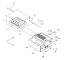
図1は、本発明の実施形態1に係る液体噴射装置の一例であるインクジェット式記録装置の概略構成を示す斜視図である。
Hereinafter, the present invention will be described in detail based on embodiments.
(Embodiment 1)
FIG. 1 is a perspective view illustrating a schematic configuration of an ink jet recording apparatus which is an example of a liquid ejecting apparatus according to
図1に示すように、本実施形態の液体噴射装置であるインクジェット式記録装置Iは、複数のインクジェット式記録ヘッドを有するインクジェット式記録ヘッドユニット1(以降、ヘッドユニット1とも言う)を具備する。ヘッドユニット1は、インク供給手段を構成するインクカートリッジ2が着脱可能に設けられ、このヘッドユニット1を搭載したキャリッジ3は、装置本体4に取り付けられたキャリッジ軸5に軸方向移動自在に設けられている。このヘッドユニット1は、ブラックインク組成物及びカラーインク組成物を吐出するものとしている。
As shown in FIG. 1, an ink jet recording apparatus I which is a liquid ejecting apparatus of the present embodiment includes an ink jet recording head unit 1 (hereinafter also referred to as a head unit 1) having a plurality of ink jet recording heads. The
また、キャリッジ軸5の一端部近傍には、駆動モーター6が設けられており、駆動モーター6の軸の先端部には外周に溝を有する第1のプーリー6aが設けられている。さらに、キャリッジ軸5の他端部近傍には、駆動モーター6の第1のプーリー6aに対応する第2のプーリー6bが回転自在に設けられており、これら第1のプーリー6aと第2のプーリー6bとの間には環状でゴム等の弾性部材からなるタイミングベルト7が掛けられている。
A drive motor 6 is provided near one end of the carriage shaft 5, and a
そして、駆動モーター6の駆動力がタイミングベルト7を介してキャリッジ3に伝達されることで、ヘッドユニット1を搭載したキャリッジ3はキャリッジ軸5に沿って移動される。一方、装置本体4にはキャリッジ3に沿ってプラテン8が設けられている。このプラテン8は図示しない紙送りモーターの駆動力により回転できるようになっており、給紙ローラーなどにより給紙された紙等の被噴射媒体(記録媒体)である記録シートSがプラテン8に巻き掛けられて搬送されるようになっている。
Then, the driving force of the driving motor 6 is transmitted to the
また、キャリッジ3の移動方向の端部であるプラテン8の側方には、詳しくは後述するインクジェット式記録ヘッドの液体噴射面をクリーニングするクリーニング手段30が設けられている。
A
ここで、インクジェット式記録装置に搭載されるインクジェット式記録ヘッドユニットについて図2及び図3を参照して説明する。なお、図2は、インクジェット式記録ヘッドユニットの概略斜視図であり、図3は、インクジェット式記録ヘッドユニットの液体噴射面側の平面図である。 Here, an ink jet recording head unit mounted on the ink jet recording apparatus will be described with reference to FIGS. 2 is a schematic perspective view of the ink jet recording head unit, and FIG. 3 is a plan view of the liquid ejecting surface side of the ink jet recording head unit.
図示するように、インクジェット式記録ヘッドユニット1は、複数のインクジェット式記録ヘッド10と、複数のインクジェット式記録ヘッド10を保持する保持部材20と、を具備する。
As illustrated, the ink jet
インクジェット式記録ヘッド10は、一方面に液体としてインク滴を吐出するノズル開口11が開口する液体噴射面12が設けられている。本実施形態では、ノズル開口11が第1の方向Xに並設されたノズル列を、第1の方向Xに直交する第2の方向Yに2列設けた。
The ink
また、インクジェット式記録ヘッド10の図示しない内部にはノズル開口11に連通する流路と、流路内のインクに圧力変化を生じさせる圧力発生手段等が設けられている。かかる圧力発生手段としては、例えば、電気機械変換機能を呈する圧電材料を有する圧電アクチュエーターの変形によって液体流路の容積を変化させて液体流路内のインクに圧力変化を生じさせてノズル開口からインク滴を吐出させるものや、流路内に発熱素子を配置して、発熱素子の発熱で発生するバブルによってノズル開口からインク滴を吐出するものや、振動板と電極との間に静電気力を発生させて、静電気力によって振動板を変形させてノズル開口からインク滴を吐出させるいわゆる静電式アクチュエーターなどを使用することができる。
Further, inside the ink jet recording head 10 (not shown), a flow path communicating with the
また、インクジェット式記録ヘッド10のノズル開口11が開口する液体噴射面12側には、ノズル開口11を露出した状態で当該液体噴射面12を覆うカバーヘッド13が設けられている。
A
カバーヘッド13は、液体噴射面12のノズル開口11を露出する貫通した露出開口部14が設けられている。
The
露出開口部14は、インクジェット式記録ヘッド10のノズル開口11の2列を露出可能な面積を有する。また、カバーヘッド13は、液体噴射面12の端部の4辺を覆い、側面側に屈曲するように設けられている。
The
このようなインクジェット式記録ヘッド10には、第1の方向Xの両端部側から外側に突出する一対のフランジ部15が設けられている。
Such an ink
保持部材20は、複数のインクジェット式記録ヘッド10、本実施形態では、4個のインクジェット式記録ヘッド10が挿入される保持孔21が設けられた金属又は樹脂等の板状部材からなる。
The holding
保持部材20の保持孔21は、第1の方向Xの幅が、インクジェット式記録ヘッド10の液体噴射面12側の先端部よりも幅広で、且つフランジ部15よりも若干小さい幅を有する。また、保持孔21の第2の方向Yの幅は、本実施形態では、インクジェット式記録ヘッド10の第2の方向Yの幅を4つ合わせた幅よりも若干大きい開口を有する。これにより、保持部材20の1つの保持孔21には、4つのインクジェット式記録ヘッド10の液体噴射面12側が挿入される。また、保持孔21にノズル開口11側が挿入されたインクジェット式記録ヘッド10は、フランジ部15が、保持孔21の周縁部に当接されてねじ等の固定手段22によって固定される。
The holding
このように、1つの保持部材20に固定される4つのインクジェット式記録ヘッド10は、ノズル開口11の相対的な位置が互いに位置決めされた状態で保持部材20に固定されている。
Thus, the four inkjet recording heads 10 fixed to one holding
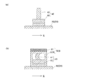
ここで、このようなインクジェット式記録ヘッドユニットをクリーニングするクリーニング手段について図4〜図6を参照して説明する。なお、図4は、本発明の実施形態1に係るインクジェット式記録ヘッドユニットとクリーニング手段とを示す概略斜視図であり、図5は、クリーニング手段を示す第1の方向の要部断面図であり、図6は、クリーニング状態を示す第2の方向の要部断面図である。 Here, a cleaning means for cleaning such an ink jet recording head unit will be described with reference to FIGS. 4 is a schematic perspective view showing the ink jet recording head unit and the cleaning means according to the first embodiment of the present invention, and FIG. 5 is a cross-sectional view of the main part in the first direction showing the cleaning means. FIG. 6 is a cross-sectional view of the main part in the second direction showing the cleaning state.
図示するように、クリーニング手段30は、上部(インクジェット式記録ヘッド10側)が開口した箱形状を有するクリーニング装置本体31と、クリーニング装置本体31に移動可能に設けられた保持部材32と、保持部材32に着脱可能に保持された液体噴射面清掃部材40及びカバーヘッド清掃部材50と、を具備する。
As shown in the figure, the cleaning means 30 includes a cleaning device
保持部材32は、クリーニング装置本体31の開口部に、キャリッジ3の移動方向とは直交する方向、すなわち、第1の方向Xに向かって移動可能に設けられている。具体的には、保持部材32は、板状の保持部33と、保持部33の両端部を屈曲することで設けられた2つの脚部34と、を具備し、2つの脚部34がクリーニング装置本体31の相対する2つの側面の外側に配置されることで、保持部33がクリーニング装置本体31の開口に跨って設けられている。
The holding
また、保持部33上(クリーニング装置本体31とは反対側)には、液体噴射面清掃部材40が着脱可能に保持されている。
Further, the liquid ejection
液体噴射面清掃部材40は、第1部材41と、第1部材41を保持する第1ベース部42と、を具備する。
The liquid ejection
第1部材41は、ゴムやエラストマー等の弾性材料からなる板状部材であり、第1部材41の先端が自由端となるように、その基端部が第1ベース部42に固定されている。
The
また、第1部材41は、当該第1部材41の一方面側が凹となるように第2の方向Yの直線に対して湾曲した状態で第1ベース部42に固定されている。なお、第1部材41は、図6(a)に示すように、保持部材32の移動方向である第1の方向Xに直交する第2の方向Yの幅が、カバーヘッド13の第2の方向Yの幅よりも幅広に設けられている。
The
さらに、第1部材41の自由端となる先端は、面方向において、両端部側から中央部に向かって徐々に突出して設けられている。
Furthermore, the front end that is the free end of the
第1部材41をこのような形状とすることで、第1部材41は、保持部材32によって第1の方向Xに移動することで、その中央部の突出した領域が液体噴射面12に摺接して、液体噴射面12をクリーニングする。すなわち、第1部材41は、カバーヘッド13の表面にほとんど接触しないように設けられている。
By forming the
第1ベース部42は、金属や樹脂等の板状部材からなり、一方面に第1部材41の基端部が固定されている。また、第1ベース部42には、第2の方向Yの第1部材41の両側に、固定孔43が設けられている。
The
そして、液体噴射面清掃部材40は、第1ベース部42に設けられた固定孔43を挿通した雄ねじからなるねじ部材60を保持部材32に螺合させることで保持部材32に着脱可能に保持されている。
The liquid ejection
また、保持部材32には、カバーヘッド清掃部材50が着脱可能に保持されている。カバーヘッド清掃部材50は、第2部材51と、第2部材51を保持する第2ベース部52と、を具備する。
Further, the cover
第2部材51は、液体であるインクを吸水可能な液体吸収材からなる。第2部材51として用いられる液体吸収材としては、例えば、ポリウレタン等の樹脂材料などで形成された多孔質材料や、パルプ、合成繊維又は乾式パルプ不織布等の繊維質材料などが挙げられる。本実施形態では、第2部材51として、合成繊維の不織布を用いた。
The
このような第2部材51は、図6(b)に示すように、第2の方向Yの幅が、カバーヘッド13の第2の方向Yの幅よりも幅広となるように設けられている。なお、第2部材51は、第2の方向Yで隣り合うインクジェット式記録ヘッド10のカバーヘッド13に跨って接触する幅で設けてもよい。
6B, the
第2ベース部52は、金属や樹脂等の板状部材からなり、一方面に第2部材51が保持されている。また、第2ベース部52には、第2の方向Yの第2部材51の両側に、固定孔53が設けられている。
The
そして、カバーヘッド清掃部材50は、第2ベース部52に設けられた固定孔53を挿通した雄ねじからなるねじ部材60を保持部材32に螺合させることで保持部材32に着脱可能に保持されている。
The cover
すなわち、保持部材32には、液体噴射面清掃部材40とカバーヘッド清掃部材50とが着脱可能に保持され、且つ液体噴射面清掃部材40とカバーヘッド清掃部材50とは交換可能となっている。
That is, the liquid ejection
このような保持部材32は、クリーニング装置本体31の内部に設けられたモーター35によって駆動される。具体的には、クリーニング装置本体31内に設けられたモーター35はクリーニング装置本体31の一側面に固定されている。このモーター35の回転軸35aは、クリーニング装置本体31の一側面から外部に突出して設けられており、一側面から突出した回転軸35aには円形歯車である小歯車36が設けられている。また、クリーニング装置本体31の小歯車36が設けられた一側面には、小歯車36に噛み合う円形歯車である大歯車37が回転可能に設けられている。そして、保持部材32の脚部34には、大歯車37に噛み合う直線歯車であるラックが設けられており、モーター35の回転は、小歯車36及び大歯車37を介してラックが設けられた脚部34に伝わり、保持部材32をクリーニング装置本体31の開口に沿って水平移動させる。
Such a holding
このようなクリーニング手段30では、印刷開始前、印刷中、印刷後及び定期的なタイミングで、図5(a)及び図6(b)に示すように、液体噴射面清掃部材40の第1部材41を液体噴射面12に摺接させて、液体噴射面12に付着したインクや毛羽、ホコリ、紙粉等を除去する。これにより、液体噴射面12にインクや異物が付着することによって、インク滴の吐出方向が安定しないことや、インク滴が吐出されないなどの不具合を抑制することができる。
In such a
また、定期的なタイミング、例えば、所定の印刷枚数毎に、保持部材32に固定されていた液体噴射面清掃部材40を取り外して、保持部材32にカバーヘッド清掃部材50を取り付ける。そして、図5(b)及び図6(b)に示すように、保持部材32を液体噴射面清掃部材40によって清掃するのと同じように第1の方向Xに移動させることで、カバーヘッド清掃部材50の第2部材51をカバーヘッド13の記録シートSに相対向する面に摺接させる。これにより、カバーヘッド清掃部材50の第2部材51がカバーヘッド13の記録シートSに相対向する面に付着したインクや毛羽、ホコリ、紙粉等を除去する。なお、この第2部材51は、液体吸収材で形成されているため、カバーヘッド13に付着したインクは第2部材51によって押し退けられるのではなく、吸水される。また、本実施形態の第2部材51は、多孔質材料又は繊維質材料の液体吸収材で形成されているため、カバーヘッド13に付着したホコリ、毛羽、紙粉などの異物を絡め取ることができる。ちなみに、第2部材51として剛性材料や弾性材料で形成されたスクレーパー等を用いると、カバーヘッド13に付着したインクや、ホコリ、毛羽、紙粉などの異物を押し退けるだけであり、押し退けられたインクや異物はカバーヘッド13の側面側に付着して残留してしまう。本実施形態では、第2部材51が、インクや異物を絡め取ることができるため、カバーヘッド13に付着したインクや異物をカバーヘッド13の側面に押し退けるのを抑制することができる。
Further, the liquid ejection
また、本実施形態では、第2部材51は、多孔質材料又は繊維質材料の液体吸収材からなるため、弾性変形することができる。したがって、第2部材51をカバーヘッド13の記録シートSに相対向する面に押し付けた際に、第2部材51が弾性変形して、カバーヘッド13の側面に回り込むことができる。したがって、第2部材51を移動させることで、カバーヘッド13の表面(記録シートSに相対向する面)だけなく、カバーヘッド13の側面に付着したインクや異物を除去することができる。
Moreover, in this embodiment, since the
ちなみに、第2部材51を第1部材41と共に常に保持部材32に保持させることも考えられるが、第2部材51をインクジェット式記録装置I内に常に配置しておくと、第2部材51は、液体吸収材で形成されているため、ミストとなったインクを吸水すると共に、ホコリや毛羽、紙粉などの異物が吸着されてしまう。そして、インクや異物を吸着した第2部材51をカバーヘッド13に摺接すると、第2部材51に吸着されたインクや異物が逆にカバーヘッド13に付着し、カバーヘッド13を汚してしまう。本実施形態では、第2部材51を保持部材32に着脱可能に保持させることで、インクジェット式記録装置I内に第2部材51を常に配置することなく、メンテナンス時のみに第2部材51をインクジェット式記録装置I内に載置することができるため、第2部材51によってカバーヘッド13が汚れるのを抑制することができる。
Incidentally, it is conceivable to always hold the
そして、このように第2部材51(カバーヘッド清掃部材50)によるカバーヘッド13のクリーニングが終わったら、カバーヘッド清掃部材50を保持部材32から取り外して、保持部材32に液体噴射面清掃部材40を取り付ける。
When the
すなわち、カバーヘッド清掃部材50は、カバーヘッド13のクリーニングなどのメンテナンス時にのみ保持部材32に取り付けられるものであり、通常の使用時(印刷時や印刷待機時)には、保持部材32には液体噴射面清掃部材40が取り付けられている。
In other words, the cover
なお、第2部材51は、液体吸収材からなるため、第2部材51に洗浄液を染み込ませた状態で、カバーヘッド13のクリーニングを行うようにしてもよい。このような洗浄液としては、特に限定されないが、液体噴射面12や、インクジェット式記録ヘッド10の流路内等に付着しても問題ないものを用いるのが好ましい。例えば、インクジェット式記録ヘッド10の製造時に流路内に界面活性剤を含む洗浄液を流通させて流路内のクリーニングを行うが、この流路内のクリーニングに用いられる洗浄液を第2部材51に染み込ませればよい。このように、第2部材51に洗浄液を染み込ませてカバーヘッド13のクリーニングを行うことで、カバーヘッド13に付着して固化したインクや異物などを容易に除去することができると共に、インクジェット式記録ヘッド10の流路を洗浄する洗浄液を用いることで、洗浄液が液体噴射面12や流路内に付着しても洗浄液によってインクジェット式記録ヘッド10が破壊される等の不具合の発生を抑制することができる。
Since the
なお、本実施形態では、第2部材51は、第2の方向Yの幅を、各インクジェット式記録ヘッド10のカバーヘッド13よりも若干大きな幅で設け、第2部材51は、各インクジェット式記録ヘッド10のカバーヘッド13に個別に摺接するようにしたが、特にこれに限定されない。ここで、第2部材の他の例を図7に示す。なお、図7は、本発明の実施形態1に係る第2部材の変形例を示す斜視図である。
In the present embodiment, the
図7に示すように、カバーヘッド清掃部材50Aは、第2部材51Aと、第2ベース部52Aと、を具備する。第2部材51Aは、第2の方向Yの幅が、ヘッドユニット1に設けられた複数のインクジェット式記録ヘッド10の全てのカバーヘッド13に摺接する幅で設けられている。このような第2部材51Aでは、同時に全てのインクジェット式記録ヘッド10のカバーヘッド13をクリーニングすることができるため、インクジェット式記録ヘッド10のカバーヘッド13を1つずつクリーニングする場合に比べて、短時間でクリーニングすることができる。
As shown in FIG. 7, the cover
また、本実施形態では、液体噴射面清掃部材40とカバーヘッド清掃部材50とを交換可能としたが、特にこれに限定されるものではない。ここで、クリーニング手段の他の例を図8に示す。なお、図8は、本発明の実施形態1に係るクリーニング手段の変形例を示す断面図である。
In the present embodiment, the liquid ejection
図8(b)に示すように、カバーヘッド清掃部材50Bは、第2部材51と、第2部材51を保持する第2ベース部52Bと、を具備する。
As illustrated in FIG. 8B, the cover
第2ベース部52Bは、第2部材51が固定された面とは反対面側が開口する箱形状を有する。そして、図8(b)に示すように、カバーヘッド清掃部材50Bの第2ベース部52Bは、保持部材32に保持された液体噴射面清掃部材40に嵌合する。
The
すなわち、図8に示す例では、保持部材32に固定された第1部材41を有する液体噴射面清掃部材40を取り外すことなく、保持部材32にカバーヘッド清掃部材50Bを取り付けることができる。このため、液体噴射面清掃部材40を取り外す工程が不要となり、メンテナンスを容易に且つ短時間で行うことができる。
That is, in the example shown in FIG. 8, the cover
(他の実施形態)
以上、本発明の一実施形態について説明したが、本発明の基本的構成は上述したものに限定されるものではない。例えば、上述した実施形態1では、カバーヘッド清掃部材50、50Aを保持部材32に固定した際に、液体噴射面清掃部材40が液体噴射面12に接触しないようにしたが、特にこれに限定されず、例えば、保持部材32の液体噴射面清掃部材40とは別の場所にカバーヘッド清掃部材50、50Aを着脱可能に固定するようにしてもよい。すなわち、カバーヘッド清掃部材50、50Aによってカバーヘッド13をクリーニングする際に、同時に液体噴射面12を液体噴射面清掃部材40によってクリーニングするようにしてもよい。
(Other embodiments)
As mentioned above, although one Embodiment of this invention was described, the basic composition of this invention is not limited to what was mentioned above. For example, in the first embodiment described above, when the cover
また、上述した実施形態1では、インクジェット式記録ヘッドユニットが、4個のインクジェット式記録ヘッド10を保持するようにしたが、特にこれに限定されず、インクジェット式記録ヘッド10が1個であってもよく、また、インクジェット式記録ヘッド10が2〜3個又は5個以上保持されていてもよい。ちなみに、インクジェット式記録ヘッド10が1個の場合には、実質的にインクジェット式記録ヘッド10がインクジェット式記録ヘッドユニットとなる。
In the first embodiment described above, the ink jet recording head unit holds four ink jet recording heads 10. However, the present invention is not limited to this, and there is one ink
さらに、上述した実施形態1では、インクジェット式記録ヘッド10(ヘッドユニット1)がキャリッジ3に搭載されて主走査方向に移動するインクジェット式記録装置Iを例示したが、特にこれに限定されず、例えば、インクジェット式記録ヘッド10が固定されて、紙等の記録シートSを副走査方向に移動させるだけで印刷を行う、所謂ライン式記録装置にも本発明を適用することができる。なお、ライン式記録装置の場合には、クリーニング手段30が記録シートSの搬送方向とは直交する方向に移動すればよい。
Furthermore, in the first embodiment described above, the ink jet recording apparatus I in which the ink jet recording head 10 (head unit 1) is mounted on the
なお、上記実施の形態においては、液体噴射ヘッドの一例としてインクジェット式記録ヘッドを、また液体噴射装置の一例としてインクジェット式記録装置を挙げて説明したが、本発明は、広く液体噴射ヘッド及び液体噴射装置全般を対象としたものであり、インク以外の液体を噴射する液体噴射ヘッドや液体噴射装置にも勿論適用することができる。その他の液体噴射ヘッドとしては、例えば、プリンター等の画像記録装置に用いられる各種の記録ヘッド、液晶ディスプレイ等のカラーフィルターの製造に用いられる色材噴射ヘッド、有機ELディスプレイ、FED(電界放出ディスプレイ)等の電極形成に用いられる電極材料噴射ヘッド、バイオchip製造に用いられる生体有機物噴射ヘッド等が挙げられ、かかる液体噴射ヘッドを備えた液体噴射装置にも適用できる。 In the above embodiment, an ink jet recording head has been described as an example of a liquid ejecting head, and an ink jet recording apparatus has been described as an example of a liquid ejecting apparatus. The present invention is intended for the entire apparatus, and can of course be applied to a liquid ejecting head and a liquid ejecting apparatus that eject liquid other than ink. Other liquid ejecting heads include, for example, various recording heads used in image recording apparatuses such as printers, color material ejecting heads used in the manufacture of color filters such as liquid crystal displays, organic EL displays, and FEDs (field emission displays). Examples thereof include an electrode material ejection head used for electrode formation, a bio-organic matter ejection head used for biochip production, and the like, and can also be applied to a liquid ejection apparatus provided with such a liquid ejection head.
I インクジェット式記録装置(液体噴射装置)、 1 インクジェット式記録ヘッドユニット(液体噴射ヘッドユニット)、 10 インクジェット式記録ヘッド(液体噴射ヘッド)、 11 ノズル開口、 12 液体噴射面、 13 カバーヘッド、 30 クリーニング手段、 32 保持部材、 40 液体噴射面清掃部材、 41 第1部材、 50、50A、50B カバーヘッド清掃部材、 51、51A 第2部材 I ink jet recording apparatus (liquid ejecting apparatus), 1 ink jet recording head unit (liquid ejecting head unit), 10 ink jet recording head (liquid ejecting head), 11 nozzle opening, 12 liquid ejecting surface, 13 cover head, 30 cleaning Means, 32 holding member, 40 liquid ejection surface cleaning member, 41 first member, 50, 50A, 50B cover head cleaning member, 51, 51A second member
Claims (10)
前記液体噴射面に摺接可能に設けられて弾性部材からなる第1部材を保持すると共に、前記液体噴射面の面方向に移動可能に設けられた保持部材に、液体吸収材からなる第2部材を着脱可能に保持させて、前記保持部材を前記液体噴射面の面方向に移動させることで、前記第2部材を前記カバーヘッドに摺接させて、当該第2部材で前記カバーヘッドをワイピングし、
前記第1部材が前記保持部材に着脱可能に保持されていると共に、前記第2部材は、前記第1部材と交換することで当該第2部材を前記保持部材に保持させることを特徴とする液体噴射ヘッドのメンテナンス方法。 Maintenance of a liquid ejecting head comprising: a liquid ejecting surface having a nozzle opening for ejecting liquid; and a cover head provided on the liquid ejecting surface and covering the liquid ejecting surface with the nozzle opening exposed. A method,
A first member made of an elastic member is provided so as to be slidable in contact with the liquid ejecting surface, and a second member made of a liquid absorbing material is provided on a holding member provided to be movable in the surface direction of the liquid ejecting surface. Is held detachably, and the holding member is moved in the surface direction of the liquid ejecting surface to bring the second member into sliding contact with the cover head, and the cover member is wiped by the second member. ,
The first member is detachably held by the holding member, and the second member exchanges the first member to hold the second member on the holding member. Maintenance method of the ejection head.
前記液体噴射面に摺接可能に設けられて弾性部材からなる第1部材を保持すると共に、前記液体噴射面の面方向に移動可能に設けられた保持部材に、液体吸収材からなる第2部材を着脱可能に保持させて、前記保持部材を前記液体噴射面の面方向に移動させることで、前記第2部材を前記カバーヘッドに摺接させて、当該第2部材で前記カバーヘッドをワイピングし、A first member made of an elastic member is provided so as to be slidable in contact with the liquid ejecting surface, and a second member made of a liquid absorbing material is provided on a holding member provided to be movable in the surface direction of the liquid ejecting surface. Is held detachably, and the holding member is moved in the surface direction of the liquid ejecting surface to bring the second member into sliding contact with the cover head, and the cover member is wiped by the second member. ,
前記液体噴射ヘッドが複数設けられており、前記第2部材が複数の前記液体噴射ヘッドの前記カバーヘッドに同時に摺接する長さで設けられていることを特徴とする液体噴射ヘッドのメンテナンス方法。A maintenance method for a liquid ejecting head, comprising: a plurality of the liquid ejecting heads; and the second member having a length that simultaneously slides on the cover heads of the plurality of liquid ejecting heads.
前記液体噴射面に摺接可能に設けられて弾性部材からなる第1部材を保持すると共に、前記液体噴射面の面方向に移動可能に設けられた保持部材に、液体吸収材からなる第2部材を着脱可能に保持させて、前記保持部材を前記液体噴射面の面方向に移動させることで、前記第2部材を前記カバーヘッドに摺接させて、当該第2部材で前記カバーヘッドをワイピングし、A first member made of an elastic member is provided so as to be slidable in contact with the liquid ejecting surface, and a second member made of a liquid absorbing material is provided on a holding member provided to be movable in the surface direction of the liquid ejecting surface. Is held detachably, and the holding member is moved in the surface direction of the liquid ejecting surface to bring the second member into sliding contact with the cover head, and the cover member is wiped by the second member. ,
前記第1部材を用いたクリーニングを、印刷時に行い、The cleaning using the first member is performed at the time of printing,
前記第2部材を用いたクリーニングを、印刷時に行わないことを特徴とする液体噴射ヘッドのメンテナンス方法。A maintenance method for a liquid jet head, wherein the cleaning using the second member is not performed during printing.
前記第2部材を用いたクリーニングを、印刷時に行わないことを特徴とする請求項1若しくは請求項2に記載の、又は、請求項3を引用しない請求項4〜6の何れか一項に記載の液体噴射ヘッドのメンテナンス方法。 The cleaning using the first member is performed at the time of printing,
The cleaning using the second member is not performed at the time of printing , or according to any one of claims 4 to 6, wherein the third member is not cited. Maintenance method for liquid jet head.
前記液体噴射ヘッドの前記液体噴射面の面方向に移動可能に設けられた保持部材と、
該保持部材に保持されて、前記液体噴射面に摺接する弾性部材からなる第1部材と、
前記保持部材に着脱可能に保持されて、前記カバーヘッドに摺接する液体吸収材からなる第2部材と、を具備し、
前記第1部材は、前記保持部材に着脱可能に保持され、
前記第2部材は、前記第1部材と交換されることにより前記保持部材に保持される
ことを特徴とする液体噴射装置。 A liquid ejecting head comprising: a liquid ejecting surface having a nozzle opening for ejecting liquid; and a cover head provided on the liquid ejecting surface and covering the liquid ejecting surface with the nozzle opening exposed.
A holding member provided movably in the surface direction of the liquid ejecting surface of the liquid ejecting head;
A first member made of an elastic member held by the holding member and in sliding contact with the liquid ejection surface;
A second member made of a liquid absorbent material detachably held by the holding member and in sliding contact with the cover head ,
The first member is detachably held on the holding member,
The liquid ejecting apparatus according to claim 1, wherein the second member is held by the holding member by being replaced with the first member .
前記液体噴射ヘッドの前記液体噴射面の面方向に移動可能に設けられた保持部材と、A holding member provided movably in the surface direction of the liquid ejecting surface of the liquid ejecting head;
該保持部材に保持されて、前記液体噴射面に摺接する弾性部材からなる第1部材と、A first member made of an elastic member held by the holding member and in sliding contact with the liquid ejection surface;
前記保持部材に着脱可能に保持されて、前記カバーヘッドに摺接する液体吸収材からなる第2部材と、を具備し、A second member made of a liquid absorbent material detachably held by the holding member and in sliding contact with the cover head,
前記液体噴射ヘッドは、複数設けられており、A plurality of the liquid jet heads are provided,
前記第2部材は、複数の前記液体噴射ヘッドの前記カバーヘッドに同時に摺接する長さで設けられているThe second member is provided with a length that is in sliding contact with the cover heads of the plurality of liquid jet heads simultaneously.
ことを特徴とする液体噴射装置。A liquid ejecting apparatus.
前記液体噴射ヘッドの前記液体噴射面の面方向に移動可能に設けられた保持部材と、A holding member provided movably in the surface direction of the liquid ejecting surface of the liquid ejecting head;
該保持部材に保持されて、前記液体噴射面に摺接する弾性部材からなる第1部材と、A first member made of an elastic member held by the holding member and in sliding contact with the liquid ejection surface;
前記保持部材に着脱可能に保持されて、前記カバーヘッドに摺接する液体吸収材からなる第2部材と、を具備し、A second member made of a liquid absorbent material detachably held by the holding member and in sliding contact with the cover head,
前記第1部材が前記保持部材に保持された状態で印刷を行い、Printing is performed with the first member held by the holding member;
前記第2部材が前記保持部材に保持された状態で印刷を行わないPrinting is not performed with the second member held by the holding member.
ことを特徴とする液体噴射装置。A liquid ejecting apparatus.
Priority Applications (1)
| Application Number | Priority Date | Filing Date | Title |
|---|---|---|---|
| JP2012189629A JP6056275B2 (en) | 2012-08-30 | 2012-08-30 | Liquid ejecting head maintenance method and liquid ejecting apparatus |
Applications Claiming Priority (1)
| Application Number | Priority Date | Filing Date | Title |
|---|---|---|---|
| JP2012189629A JP6056275B2 (en) | 2012-08-30 | 2012-08-30 | Liquid ejecting head maintenance method and liquid ejecting apparatus |
Publications (3)
| Publication Number | Publication Date |
|---|---|
| JP2014046502A JP2014046502A (en) | 2014-03-17 |
| JP2014046502A5 JP2014046502A5 (en) | 2015-10-08 |
| JP6056275B2 true JP6056275B2 (en) | 2017-01-11 |
Family
ID=50606674
Family Applications (1)
| Application Number | Title | Priority Date | Filing Date |
|---|---|---|---|
| JP2012189629A Active JP6056275B2 (en) | 2012-08-30 | 2012-08-30 | Liquid ejecting head maintenance method and liquid ejecting apparatus |
Country Status (1)
| Country | Link |
|---|---|
| JP (1) | JP6056275B2 (en) |
Families Citing this family (4)
| Publication number | Priority date | Publication date | Assignee | Title |
|---|---|---|---|---|
| JP2016137649A (en) | 2015-01-28 | 2016-08-04 | セイコーエプソン株式会社 | Recording device |
| WO2017002857A1 (en) * | 2015-07-01 | 2017-01-05 | 積水化学工業株式会社 | Inkjet head cleaning device and inkjet printing apparatus |
| JP6465489B2 (en) | 2015-10-23 | 2019-02-06 | ヒューグル開発株式会社 | Cleaning head and cleaning method |
| JP7363115B2 (en) | 2019-06-12 | 2023-10-18 | ブラザー工業株式会社 | liquid discharge head |
Family Cites Families (4)
| Publication number | Priority date | Publication date | Assignee | Title |
|---|---|---|---|---|
| JP3794206B2 (en) * | 1999-06-18 | 2006-07-05 | セイコーエプソン株式会社 | Inkjet recording device |
| JP4501447B2 (en) * | 2004-02-16 | 2010-07-14 | ソニー株式会社 | Head cap, head cartridge, and liquid ejection device |
| JP5041823B2 (en) * | 2006-02-28 | 2012-10-03 | エスアイアイ・プリンテック株式会社 | Ink jet recording apparatus and ink jet recording head |
| JP2010099880A (en) * | 2008-10-22 | 2010-05-06 | Ricoh Co Ltd | Liquid discharge head and image forming apparatus |
-
2012
- 2012-08-30 JP JP2012189629A patent/JP6056275B2/en active Active
Also Published As
| Publication number | Publication date |
|---|---|
| JP2014046502A (en) | 2014-03-17 |
Similar Documents
| Publication | Publication Date | Title |
|---|---|---|
| JP5352409B2 (en) | CLEANER CARTRIDGE, CLEANING DEVICE, AND IMAGE FORMING DEVICE | |
| JP6044307B2 (en) | Liquid ejector | |
| JP2009286077A (en) | Inkjet head cleaning device and inkjet head cleaning method | |
| JP7010047B2 (en) | Head cleaning device and liquid discharge device | |
| JP6248556B2 (en) | Liquid ejecting head cleaning device and liquid ejecting device provided with the cleaning device | |
| JP5494940B2 (en) | Recording device | |
| JP6056275B2 (en) | Liquid ejecting head maintenance method and liquid ejecting apparatus | |
| JP6418207B2 (en) | Liquid ejector | |
| JP2018079684A (en) | Head cleaning device, head maintenance device and device for discharging liquid | |
| JP6194576B2 (en) | Liquid ejector | |
| JP2005313606A (en) | Wiper cleaning device for liquid ejection device | |
| JP2012143947A (en) | Liquid wiping unit, and liquid jetting apparatus | |
| JP3961005B2 (en) | Inkjet printer | |
| US9108412B2 (en) | Cleaning member and liquid ejecting apparatus | |
| JP2017071135A (en) | Cleaning device and ink jet printer with the same | |
| US10464327B2 (en) | Inkjet recording device and method for maintaining same | |
| JP4144556B2 (en) | Liquid discharge head cleaning device and liquid discharge device | |
| JP2019162850A (en) | Wiping member, wiping method and image formation device | |
| JP6308096B2 (en) | Inkjet recording device | |
| JP2010214608A (en) | Liquid ejecting apparatus | |
| JP6020098B2 (en) | Liquid ejection device | |
| JP2013126772A (en) | Recording apparatus | |
| JP4947206B2 (en) | Wiper cleaning device for liquid ejector | |
| US11865842B2 (en) | Cleaning unit, liquid ejecting apparatus, and method for replacing cleaning unit | |
| JP4930089B2 (en) | Recording device |
Legal Events
| Date | Code | Title | Description |
|---|---|---|---|
| RD04 | Notification of resignation of power of attorney |
Free format text: JAPANESE INTERMEDIATE CODE: A7424 Effective date: 20150108 |
|
| A521 | Written amendment |
Free format text: JAPANESE INTERMEDIATE CODE: A523 Effective date: 20150819 |
|
| A621 | Written request for application examination |
Free format text: JAPANESE INTERMEDIATE CODE: A621 Effective date: 20150819 |
|
| A977 | Report on retrieval |
Free format text: JAPANESE INTERMEDIATE CODE: A971007 Effective date: 20160525 |
|
| A131 | Notification of reasons for refusal |
Free format text: JAPANESE INTERMEDIATE CODE: A131 Effective date: 20160607 |
|
| RD04 | Notification of resignation of power of attorney |
Free format text: JAPANESE INTERMEDIATE CODE: A7424 Effective date: 20160609 |
|
| RD03 | Notification of appointment of power of attorney |
Free format text: JAPANESE INTERMEDIATE CODE: A7423 Effective date: 20160623 |
|
| A521 | Written amendment |
Free format text: JAPANESE INTERMEDIATE CODE: A523 Effective date: 20160722 |
|
| TRDD | Decision of grant or rejection written | ||
| A01 | Written decision to grant a patent or to grant a registration (utility model) |
Free format text: JAPANESE INTERMEDIATE CODE: A01 Effective date: 20161108 |
|
| A61 | First payment of annual fees (during grant procedure) |
Free format text: JAPANESE INTERMEDIATE CODE: A61 Effective date: 20161121 |
|
| R150 | Certificate of patent or registration of utility model |
Ref document number: 6056275 Country of ref document: JP Free format text: JAPANESE INTERMEDIATE CODE: R150 |