JP6052028B2 - Motor control device - Google Patents
Motor control device Download PDFInfo
- Publication number
- JP6052028B2 JP6052028B2 JP2013077847A JP2013077847A JP6052028B2 JP 6052028 B2 JP6052028 B2 JP 6052028B2 JP 2013077847 A JP2013077847 A JP 2013077847A JP 2013077847 A JP2013077847 A JP 2013077847A JP 6052028 B2 JP6052028 B2 JP 6052028B2
- Authority
- JP
- Japan
- Prior art keywords
- motor
- bridge circuit
- circuit
- air
- duty ratio
- Prior art date
- Legal status (The legal status is an assumption and is not a legal conclusion. Google has not performed a legal analysis and makes no representation as to the accuracy of the status listed.)
- Expired - Fee Related
Links
Images


Classifications
-
- H—ELECTRICITY
- H02—GENERATION; CONVERSION OR DISTRIBUTION OF ELECTRIC POWER
- H02P—CONTROL OR REGULATION OF ELECTRIC MOTORS, ELECTRIC GENERATORS OR DYNAMO-ELECTRIC CONVERTERS; CONTROLLING TRANSFORMERS, REACTORS OR CHOKE COILS
- H02P5/00—Arrangements specially adapted for regulating or controlling the speed or torque of two or more electric motors
- H02P5/68—Arrangements specially adapted for regulating or controlling the speed or torque of two or more electric motors controlling two or more dc dynamo-electric motors
-
- B—PERFORMING OPERATIONS; TRANSPORTING
- B60—VEHICLES IN GENERAL
- B60H—ARRANGEMENTS OF HEATING, COOLING, VENTILATING OR OTHER AIR-TREATING DEVICES SPECIALLY ADAPTED FOR PASSENGER OR GOODS SPACES OF VEHICLES
- B60H1/00—Heating, cooling or ventilating [HVAC] devices
-
- B—PERFORMING OPERATIONS; TRANSPORTING
- B60—VEHICLES IN GENERAL
- B60H—ARRANGEMENTS OF HEATING, COOLING, VENTILATING OR OTHER AIR-TREATING DEVICES SPECIALLY ADAPTED FOR PASSENGER OR GOODS SPACES OF VEHICLES
- B60H1/00—Heating, cooling or ventilating [HVAC] devices
- B60H1/00421—Driving arrangements for parts of a vehicle air-conditioning
- B60H1/00428—Driving arrangements for parts of a vehicle air-conditioning electric
-
- B—PERFORMING OPERATIONS; TRANSPORTING
- B60—VEHICLES IN GENERAL
- B60H—ARRANGEMENTS OF HEATING, COOLING, VENTILATING OR OTHER AIR-TREATING DEVICES SPECIALLY ADAPTED FOR PASSENGER OR GOODS SPACES OF VEHICLES
- B60H1/00—Heating, cooling or ventilating [HVAC] devices
- B60H1/00642—Control systems or circuits; Control members or indication devices for heating, cooling or ventilating devices
- B60H1/00814—Control systems or circuits characterised by their output, for controlling particular components of the heating, cooling or ventilating installation
- B60H1/00821—Control systems or circuits characterised by their output, for controlling particular components of the heating, cooling or ventilating installation the components being ventilating, air admitting or air distributing devices
- B60H1/00835—Damper doors, e.g. position control
- B60H1/00857—Damper doors, e.g. position control characterised by the means connecting the initiating means, e.g. control lever, to the damper door
-
- H—ELECTRICITY
- H02—GENERATION; CONVERSION OR DISTRIBUTION OF ELECTRIC POWER
- H02P—CONTROL OR REGULATION OF ELECTRIC MOTORS, ELECTRIC GENERATORS OR DYNAMO-ELECTRIC CONVERTERS; CONTROLLING TRANSFORMERS, REACTORS OR CHOKE COILS
- H02P21/00—Arrangements or methods for the control of electric machines by vector control, e.g. by control of field orientation
- H02P21/0003—Control strategies in general, e.g. linear type, e.g. P, PI, PID, using robust control
-
- H—ELECTRICITY
- H02—GENERATION; CONVERSION OR DISTRIBUTION OF ELECTRIC POWER
- H02P—CONTROL OR REGULATION OF ELECTRIC MOTORS, ELECTRIC GENERATORS OR DYNAMO-ELECTRIC CONVERTERS; CONTROLLING TRANSFORMERS, REACTORS OR CHOKE COILS
- H02P27/00—Arrangements or methods for the control of AC motors characterised by the kind of supply voltage
- H02P27/04—Arrangements or methods for the control of AC motors characterised by the kind of supply voltage using variable-frequency supply voltage, e.g. inverter or converter supply voltage
- H02P27/06—Arrangements or methods for the control of AC motors characterised by the kind of supply voltage using variable-frequency supply voltage, e.g. inverter or converter supply voltage using dc to ac converters or inverters
- H02P27/08—Arrangements or methods for the control of AC motors characterised by the kind of supply voltage using variable-frequency supply voltage, e.g. inverter or converter supply voltage using dc to ac converters or inverters with pulse width modulation
-
- H—ELECTRICITY
- H02—GENERATION; CONVERSION OR DISTRIBUTION OF ELECTRIC POWER
- H02P—CONTROL OR REGULATION OF ELECTRIC MOTORS, ELECTRIC GENERATORS OR DYNAMO-ELECTRIC CONVERTERS; CONTROLLING TRANSFORMERS, REACTORS OR CHOKE COILS
- H02P3/00—Arrangements for stopping or slowing electric motors, generators, or dynamo-electric converters
- H02P3/06—Arrangements for stopping or slowing electric motors, generators, or dynamo-electric converters for stopping or slowing an individual dynamo-electric motor or dynamo-electric converter
- H02P3/08—Arrangements for stopping or slowing electric motors, generators, or dynamo-electric converters for stopping or slowing an individual dynamo-electric motor or dynamo-electric converter for stopping or slowing a dc motor
-
- Y—GENERAL TAGGING OF NEW TECHNOLOGICAL DEVELOPMENTS; GENERAL TAGGING OF CROSS-SECTIONAL TECHNOLOGIES SPANNING OVER SEVERAL SECTIONS OF THE IPC; TECHNICAL SUBJECTS COVERED BY FORMER USPC CROSS-REFERENCE ART COLLECTIONS [XRACs] AND DIGESTS
- Y02—TECHNOLOGIES OR APPLICATIONS FOR MITIGATION OR ADAPTATION AGAINST CLIMATE CHANGE
- Y02T—CLIMATE CHANGE MITIGATION TECHNOLOGIES RELATED TO TRANSPORTATION
- Y02T10/00—Road transport of goods or passengers
- Y02T10/80—Technologies aiming to reduce greenhouse gasses emissions common to all road transportation technologies
- Y02T10/88—Optimized components or subsystems, e.g. lighting, actively controlled glasses
Description
本発明は、複数のモータの駆動を制御するモータ制御装置に関する。 The present invention relates to a motor control device that controls driving of a plurality of motors.
特許文献1には、空調装置のドアを駆動するための電動モータ駆動回路を簡素化した構成が開示されている。
また特許文献2には、サーボモータ制御装置において、目標値と現在値との偏差が減速開始判定値以下になった場合には減速するように制御する構成が開示されている。具体的には、減速開始判定値以下になった場合、偏差に応じて設定したデューティ比で電動モータのハイサイド金属酸化膜半導体(Metal-Oxide Semiconductor:略称MOS)またはローサイドMOSをパルス幅変調(Pulse-Width Modulation:略称PWM)で駆動することで減速している。これによって停止精度の向上および停止時の騒音を低減している。
Further,
特許文献2のように減速開始判定値以下でデューティ比を下げた場合、モータに供給される電圧が低下する。この場合、トルク変動の大きいモータおよび閉切りにトルクが必要なモードドア用のモータにおいて供給電力が不足し、目標到達前に止まってしまうという問題がある。
When the duty ratio is decreased below the deceleration start determination value as in
また前述の特許文献1の簡素化された回路に、特許文献2の減速するPWM駆動を行なった場合に、対となっているモータを同時に駆動すると、一方のモータを停止または減速すると、他方のモータも同様に停止または減速される。これによって一方のモータだけでなく他方のモータが停止することによって他方のモータの目標値への到着時間が増加するという問題がある。また一方のモータだけでなく他方のモータまでが停止すると他方のモータの停止回数が増加するので、停止時に発生する音の発生回数が多くなる。停止時に発生する音は、たとえばモータによって動作されるドアなどが筐体などに接触する際の音である。このような音は騒音の原因となるので、発生回数を減らしたいという問題がある。
In addition, in the case of performing the PWM drive that decelerates in
そこで、本発明は前述の問題点を鑑みてなされたものであり、複数のモータを駆動する駆動回路を簡素化し、各モータの停止回数を減らしつつ、パルス幅変調方式を用いて安定して動作させることができるモータ制御装置を提供することを目的とする。 Therefore, the present invention has been made in view of the above-described problems, and it is possible to simplify a drive circuit for driving a plurality of motors and to stably operate using a pulse width modulation method while reducing the number of stops of each motor. An object of the present invention is to provide a motor control device that can be made to operate.
本発明は前述の目的を達成するために以下の技術的手段を採用する。 The present invention employs the following technical means in order to achieve the aforementioned object.
本発明は、バッテリの電圧を取得する電圧取得手段(67)と、少なくとも第2ハーフブリッジ回路の各スイッチ素子をパルス幅変調方式で制御する制御手段(67)と、を含む。そして、第1、第2ハーフブリッジ回路との間には第1モータが接続され、第2、第3ハーフブリッジ回路との間には第2モータが接続される。制御手段は、第1、第2ハーフブリッジ回路を構成する4つのスイッチ素子を制御して第1、第2ハーフブリッジ回路の間で第1モータに電流を流す。また制御手段は、第2、第3ハーフブリッジ回路を構成する4つのスイッチ素子を制御して第2、第3ハーフブリッジ回路の間で第2モータに電流を流す。さらに制御手段は、電圧取得手段によって取得された電圧に応じて、第2ハーフブリッジ回路の各スイッチ素子をパルス幅変調方式で制御するためのデューティ比を変化させる。さらに制御手段は、第1モータおよび第2モータの少なくともいずれか一方が駆動中におけるデューティ比の最小値を、第1モータおよび第2モータが駆動する最低のデューティ比以上となるように設定し、第1モータおよび第2モータのいずれか一方のモータについて現在値が目標値となるように制御する場合には、目標値と現在値との差の絶対値が減速開始判定値よりも小さくなると、デューティ比を100%よりも小さく、かつ駆動する最低のデューティ比以上となるように制御し、現在値が目標値になると停止するように制御する。 The present invention includes voltage acquisition means (67) for acquiring the voltage of the battery, and control means (67) for controlling at least each switch element of the second half bridge circuit by a pulse width modulation method. A first motor is connected between the first and second half bridge circuits, and a second motor is connected between the second and third half bridge circuits. The control means controls the four switch elements constituting the first and second half bridge circuits to flow current to the first motor between the first and second half bridge circuits. In addition, the control means controls the four switch elements constituting the second and third half bridge circuits to flow current to the second motor between the second and third half bridge circuits. Further, the control means, in accordance with a voltage acquired by the voltage acquiring means, Ru each switch element of the second half-bridge circuit to change the duty ratio for controlling a pulse width modulation method. Furthermore, the control means sets the minimum value of the duty ratio during driving of at least one of the first motor and the second motor so as to be equal to or more than the lowest duty ratio driven by the first motor and the second motor, When controlling the current value to be the target value for either one of the first motor and the second motor, if the absolute value of the difference between the target value and the current value is smaller than the deceleration start determination value, the duty ratio smaller than 100%, and is controlled such that the above duty ratio of the lowest to be driven, that controls so as to stop the current value becomes the target value.
このような本発明に従えば、制御手段は、第1、第2ハーフブリッジ回路を構成する4つのスイッチ素子を制御することにより、第1モータを回転させることができる。制御手段は、同様に、第2、第3ハーフブリッジ回路を構成する4つのスイッチ素子を制御することにより、第2モータを回転させることができる。したがって第1、第2モータを回転させる際に、第2ハーフブリッジ回路を共用している。これによって1つのモータ毎に1つのフルブリッジ回路(すなわち、2つのハーフブリッジ回路)を用いる場合に比べて、回路構成を簡素化することができる。 According to the present invention as described above, the control unit can rotate the first motor by controlling the four switch elements constituting the first and second half bridge circuits. Similarly, the control means can rotate the second motor by controlling the four switch elements constituting the second and third half-bridge circuits. Therefore, the second half bridge circuit is shared when rotating the first and second motors. As a result, the circuit configuration can be simplified as compared with the case where one full bridge circuit (that is, two half bridge circuits) is used for each motor.
また制御手段は、共用する第2ハーフブリッジ回路の各スイッチ素子をパルス幅変調方式で制御する。したがって共用する第2ハーフブリッジ回路の各スイッチ素子のデューティ比を変化させることによって、第1モータと第2モータの駆動を高精度に制御することができる。そして制御手段は、電圧取得手段によって取得された電圧に応じてデューティ比を変化させる。これによってバッテリの電圧の大小によってモータの動作が異なることを防ぐことができる。たとえば取得された電圧が所定値よりも低ければ、デューティ比を大きくして各モータを動作させるための電圧を確保することができる。また、たとえば取得された電圧が所定値よりも高ければ、デューティ比を小さくして各モータが設定以上に高速で動作することを防ぐことができる。したがってデューティ比を制御することによって、各モータを安定して動作させることができる。
さらに制御手段は、第1モータまたは第2モータを所定の目標値で停止するときには、目標値に近づくにつれて、デューティ比が小さくなるように制御する。これによって目標値に近づくにつれて、各モータを減速することができる。したがって各モータの目標値の位置決め精度の向上することができる。また各モータの目標値が筐体などに接触する位置である場合には、その停止時の接触による衝撃音などの騒音を低減することができる。
The control means controls each switch element of the shared second half bridge circuit by a pulse width modulation method. Therefore, the drive of the first motor and the second motor can be controlled with high accuracy by changing the duty ratio of each switch element of the shared second half bridge circuit. The control means changes the duty ratio according to the voltage acquired by the voltage acquisition means. Thus, it is possible to prevent the operation of the motor from being different depending on the voltage level of the battery. For example, if the acquired voltage is lower than a predetermined value, it is possible to secure a voltage for operating each motor by increasing the duty ratio. For example, if the acquired voltage is higher than a predetermined value, the duty ratio can be reduced to prevent each motor from operating at a speed higher than the set value. Therefore, each motor can be stably operated by controlling the duty ratio.
Further, when the first motor or the second motor is stopped at a predetermined target value, the control means performs control so that the duty ratio decreases as the target value is approached. As a result, each motor can be decelerated as it approaches the target value. Therefore, the positioning accuracy of the target value of each motor can be improved. In addition, when the target value of each motor is a position where it contacts a housing or the like, it is possible to reduce noise such as an impact sound due to contact when the motor is stopped.
なお、前述の各手段の括弧内の符号は、後述する実施形態に記載の具体的手段との対応関係を示す一例である。 In addition, the code | symbol in the bracket | parenthesis of each above-mentioned means is an example which shows a corresponding relationship with the specific means as described in embodiment mentioned later.
(第1実施形態)
本発明の第1実施形態に関して、図1〜図8を用いて説明する。車両用空調装置10は、図1に示すように、室内エアコンユニット11を備えている。室内エアコンユニット11は、内気導入口12および外気導入口13を有する空調ケース14を備えている。内気導入口12は、車室内の空気(内気)を導入する。外気導入口13は、車室外の空気(外気)を導入する。空調ケース14は、各導入口12,13から導入した空気が通過し、車室内に向けて送風する空気通路を内部に形成する。空調ケース14には、各導入口12,13を選択的に開閉する内外気切替ドア15が設けられている。内外気切替ドア15には、リンク機構(図示せず)を介して第1直流モータ21が接続されている。したがって第1直流モータ(第1モータ)21は空気が流れる各導入口(第1通路)12,13を開閉する内外気切替ドア(第1ドア)15を駆動する。
(First embodiment)
A first embodiment of the present invention will be described with reference to FIGS. The
空調ケース14内のうち各導入口12,13の空気下流側には、遠心式送風機16が設けられている。空調ケース14内のうち遠心式送風機16の空気下流側には、遠心式送風機16から吹き出される空気を冷却するエバポレータ17が設けられている。エバポレータ17は、コンプレッサなどとともに周知の冷凍サイクルを構成するもので、空調ケース14内を流れる空気を冷却する熱交換器である。エバポレータ17の空気下流側には、エバポレータ17からの冷風を加熱するヒータコア18が設けられている。ヒータコア18は、エンジン冷却水(温水)を熱源とする熱交換機であって、エバポレータ17からの冷風を加熱する。
A
空調ケース14内のうちエバポレータ17の空気下流側には仕切り板19が設けられている。仕切り板19は、空調ケース14内を運転席側通路34および助手席側通路35に仕切っている。運転席側通路34および助手席側通路35のうちヒータコア18の側方には、バイパス通路20がそれぞれ設けられている。バイパス通路20は、エバポレータ17からの冷風をヒータコア18に対してバイパスさせる。
A
運転席側通路34および助手席側通路35のヒータコア18の空気上流側には、エアミックスドア31a,31bがそれぞれ設けられている。エアミックスドア31a,31bは、その開度によって、運転席側通路34および助手席側通路35を流れる冷風のうちヒータコア18を流れる風量とバイパス通路20を流れる風量との比を調整する。
運転席側通路34および助手席側通路35のうちヒータコア18の下流側には、ヒータコア18からの温風とバイパス通路20からの冷風とを混合する運転席側混合室32および助手席側混合室33が設けられている。ヒータコア18からの温風とバイパス通路20からの冷風とが混合されることにより、運転席側混合室32および助手席側混合室33から車室内の運転席側および助手席側に吹き出される空気温度(すなわち、空調風の温度)が調整されることになる。
Of the driver
運転席側通路34のエアミックスドア31aには、リンク機構(図示せず)を介して第3直流モータ23が接続されている。運転席側通路34のエアミックスドア31aの開度は、第3直流モータ23によって調整される。また助手席側通路35のエアミックスドア31bには、リンク機構(図示せず)を介して第4直流モータ24が接続されている。助手席側通路35のエアミックスドア31bの開度は第4直流モータ24によって調整される。
A
空調ケース14の運転席側通路34のうちヒータコア18の空気下流側には、運転席側フェイス吹出口41、運転席側フット吹出口42、および運転席側デフロスタ吹出口43が設けられている。運転席側フェイス吹出口41は、運転席側混合室32からの空気を運転者上半身に向けて吹き出す。運転席側フット吹出口42は、運転席側混合室32から運転者の下半身に空気を吹き出す。運転席側デフロスタ吹出口43は、運転席側混合室32からフロントガラスの内表面のうち運転席側領域に空気を吹き出す。
A driver-seat-
空調ケース14のうち運転席側フェイス吹出口41の空気上流側には、運転席側フェイス吹出口41を開閉する運転席側フェイス吹出口切替ドア41aが設けられている。空調ケース14のうち運転席側フット吹出口42の空気上流側には、運転席側フット吹出口42を開閉する運転席側フット吹出口切替ドア42aが設けられている。空調ケース14のうち運転席側デフロスタ吹出口43の空気上流側には、運転席側デフロスタ吹出口43を開閉する運転席側デフロスタ吹出口切替ドア43aが設けられている。
A driver-seat-side face
同様に、助手席側においても、空調ケース14には、助手席側フェイス吹出口44、助手席側フット吹出口45、助手席側デフロスタ吹出口46が設けられている。空調ケース14には、助手席側フェイス吹出口44、助手席側フット吹出口45および助手席側デフロスタ吹出口46をそれぞれ開閉するための吹出口切替ドア44a〜46aが設けられている。
Similarly, on the passenger seat side, the
各吹出口切替ドア41a〜46aは、リンク機構(図示せず)を介して第2直流モータ22に接続されている。各吹出口切替ドア41a〜46aは、リンク機構を介する第2直流モータ22の駆動よりそれぞれ独立して開閉される。したがって第2直流モータ(第2モータ)22は空気が流れる各吹出口(第2通路)41〜46を開閉する各吹出口切替ドア(第2ドア)を駆動する。
Each blower
次に、車両用空調装置10の電気的構成について説明する。車両用空調装置10は、図2に示すように、モータ制御装置60および電子制御装置(図1中A/CECUと記す)70を備える。モータ制御装置60は、空調装置用制御装置を構成するもので、第1直流モータ21、第2直流モータ22、第3直流モータ23、第4直流モータ24、第1ハーフブリッジ回路61、第2ハーフブリッジ回路62、第3ハーフブリッジ回路63、第4ハーフブリッジ回路64、第5ハーフブリッジ回路65、第6ハーフブリッジ回路66、制御部67、LINドライバ68およびレギュレータ69を備える。以下、第1ハーフブリッジ回路61〜第6ハーフブリッジ回路66を、それぞれ省略して第1回路61〜第6回路66ということがある。
Next, the electrical configuration of the
第1回路61は、一対のスイッチング素子として、プラス端子側スイッチ素子であるハイサイドトランジスタ61aとマイナス端子側スイッチ素子であるローサイドトランジスタ61bを備える。ハイサイドトランジスタ61aおよびローサイドトランジスタ61bは、バッテリ25のプラス電極(図1中Vccと記す)とバッテリ25のマイナス電極(図中グランドの記号を示す)との間で直列接続されている。本実施形態では、ハイサイドトランジスタ61aおよびローサイドトランジスタ61bとして電界効果型トランジスタが用いられている。第2回路62〜第6回路66は、第1回路61と同様に、バッテリ25のプラス電極とバッテリ25のマイナス電極との間で直列接続されている一対のハイサイドトランジスタ62a〜66aおよびローサイドトランジスタ62b〜66bを備える。以下、ハイサイドトランジスタ61a〜66aを省略してハイトラ61a〜66aということがある。またローサイドトランジスタ61b〜66bを省略して、ロートラ61b〜66bということがある。
The
第1回路61のハイトラ61aとロートラ61bとは、第1共通接続点61cで接続される。第1共通接続点61cは、第1回路61においてハイトラ61aのソース端子とロートラ61bのドレイン端子とが接続されている部位である。同様に、第2回路62〜第6回路66のハイトラ62a〜66aとロートラ62b〜66bとは、第2共通接続点62c〜第6共通接続点66cでそれぞれ接続される。そして第1共通接続点61cと第2共通接続点62cとの間には、第1モータとしての第1直流モータ21が接続されている。第1回路61は、第2回路62とともに、後述するように、第1直流モータ21の回転方向の切り替えを実施する。
The
第2回路62の第2共通接続点62cと第3回路63の第3共通接続点63cとの間には、第2モータとしての第2直流モータ22が接続されている。第2回路62は、第3回路63とともに、後述するように、第2直流モータ22の回転方向の切り替えを実施する。
A
第4回路64〜第6回路66は、第1回路61〜第3回路63と同様に構成され、第1直流モータ21および第2直流モータ22に代わる第3直流モータ23および第4直流モータ24の回転方向の切り替えを実施する。
The
制御部67は、電子制御装置70から出力される制御信号に基づいて第1回路61〜第6回路66を制御するとともに、各モータ21〜24に対応したポテンショメータ21a〜24aの出力信号をLINドライバ68を介して電子制御装置70に出力する。
The
第1ポテンショメータ21aは、第1直流モータ21の回転軸の回転角度を検出するセンサである。第2ポテンショメータ22a〜第4ポテンショメータ24aは、それぞれ、対応する各モータ21〜24の回転軸の回転角度を検出するセンサである。第2ポテンショメータ22aは第2直流モータ22に対応し、第3ポテンショメータ23aは第3直流モータ23に対応し、第4ポテンショメータ24aは第4直流モータ24に対応している。
The
LINドライバ68は、車載LANを介して電子制御装置70との間で通信し、電子制御装置70と制御部67との間のインターフェイス回路を構成する。本実施形態の車載LANの通信プロトコルとしては、LIN(Local Interconnect Network)が用いられている。レギュレータ69は、制御部67等に電力供給するために、バッテリ25のプラス電極とマイナス電極との間の電圧に基づいて一定の電源電圧(例えば5V)を制御部67等に出力する。
The
電子制御装置70は、メモリおよびマイクロコンピュータなどから構成されている周知の制御装置である。電子制御装置70は、スイッチの出力信号、複数のセンサ(図示略)の出力信号、および第1〜第4ポテンショメータ21a〜24aの出力信号に基づいて、第1〜第4直流モータ21〜24を制御するための制御処理を実行する。複数のセンサは、たとえば車室外の空気温度を検出する外気温センサ、車室内の日射強度を検出する日射センサ、およびエンジン冷却水の温度を検出する温度センサである。
The
また車両用空調装置10は各部を操作するスイッチ(図示せず)を備える。スイッチは、たとえば車室内に吹き出される空気温度を自動的に制御する自動空調モードを設定するためのスイッチである。またスイッチは、たとえば吹出モードおよび独立温度コントロールモードを設定するためのスイッチである。独立温度コントロールモードは、運転席側吹出口41〜43からの吹き出し空気温度と助手席側吹出口44〜46からの吹き出し空気温度とをそれぞれ独立に制御するモードである。
The
次に、第1回路61〜第6回路66の作動について説明する。第1回路61〜第6回路66は、制御部67によって制御される。まず、制御部67が内気モードから外気モードへ切り替えるときの制御に関して説明する。内気モードは、内外気切替ドア15により外気導入口13を閉鎖し、内気導入口12を開口して車室内の空気を導入するモードである。外気モードは内外気切替ドア15により内気導入口12を閉鎖し、外気導入口13を開口して車室外の空気を導入するモードである。
Next, the operation of the
この場合、制御部67が第1回路61のハイトラ61aをオンおよびロートラ61bをオフし、第2回路62のハイトラ62aをオフおよびロートラ62bをオンし、第3回路63のハイトラ63aおよびロートラ63bをオフする。これに伴い、バッテリ25のプラス電極とマイナス電極との間で、第1回路61のハイトラ61aから電流が図2中矢印Aのように第1直流モータ21を通して第2回路62のロートラ62bに流れる。このとき、第2直流モータ22が停止した状態で、第1直流モータ21の回転軸が一方向に回転する。回転軸の回転力はリンク機構を介して内外気切替ドア15に伝わり、内外気切替ドア15が回転して内気モードから外気モードに切り替わる。
In this case, the
次に、制御部67が外気モードから内気モードへ切り替えるときの制御に関して説明する。この場合、制御部67が第2回路62のハイトラ62aをオンおよびロートラ62bをオフし、第1回路61のハイトラ61aをオフおよびロートラ61bをオンし、第3回路63のハイトラ63aおよびロートラ63bをオフする。
Next, control when the
これに伴い、バッテリ25のプラス電極とマイナス電極との間で、第2回路62のハイトラ62aから図2中矢印Bのように第1直流モータ21を通して第1回路61のロートラ61bに流れる。このとき、第1直流モータ21の回転軸の回転方向が逆向きになり回転軸が他方向に回転する。回転軸の回転力はリンク機構を介して内外気切替ドア15に伝わり、内外気切替ドア15が回転して外気モードから内気モードに切り替わる。
Along with this, between the positive electrode and the negative electrode of the
次に、吹出口モードの切り替えるときの制御に関して説明する。吹出口モードは、第2直流モータ22を制御することによって切り替わる。第2直流モータ22およびリンク機構は、第2直流モータ22の回転軸が一方向に回転する際に、フェイスモード→バイレベルモード→フットモード→フット/デフモード→デフモードの順に吹出口モードが切り替わる。また第2直流モータ22の回転軸が他方向に回転する際には、デフモード→フット/デフモード→フットモード→バイレベルモード→フェイスモードの順に吹出口モードが切り替わる。
Next, control when switching the air outlet mode will be described. The air outlet mode is switched by controlling the
なおフェイスモードは、フェイス吹出口41,44を開口し、フット吹出口42,45を閉鎖し、かつデフロスタ吹出口43,46を閉鎖するモードである。バイレベルモードは、フェイス吹出口41,44を開口し、フット吹出口42,45を開口し、かつデフロスタ吹出口43,46を閉鎖するモードである。フットモードは、フェイス吹出口41,44を閉鎖し、フット吹出口42,45を開口し、かつデフロスタ吹出口43,46を若干開口するモードである。フット/デフモードは、フェイス吹出口41,44を閉鎖し、フット吹出口42,45を開口し、かつデフロスタ吹出口43,46を開口するモードである。デフモードは、フェイス吹出口41,44を閉鎖し、フット吹出口42,45を閉鎖し、かつデフロスタ吹出口43,46を開口するモードである。
The face mode is a mode in which the
制御部67が第1回路61のハイトラ61aおよびロートラ61bをオフし、第3回路63のハイトラ63aをオンおよびロートラ63bをオフし、第2回路62のハイトラ62aをオフおよびロートラ62bをオンする。これに伴い、バッテリ25のプラス電極とマイナス電極との間で、第3回路63のハイトラ63aから電流が図2中矢印Dのように第2直流モータ22を通して第2回路62のロートラ62bに流れる。このとき、第1直流モータ21が停止した状態で、第2直流モータ22の回転軸が一方向に回転する。回転軸の回転力はリンク機構を介して吹出口切替ドア41a〜46aに伝わる。これに伴い、吹出口切替ドア41a〜46aが作動して正順に切り替えて、フェイスモード、バイレベルモード、フットモード、フット/デフモードおよびデフモードのうちいずれかの吹出口モードが実施される。
The
同様に、制御部67が第1回路61のハイトラ61aおよびロートラ61bをオフし、第2回路62のハイトラ62aをオンおよびロートラ62bをオフし、第3回路63のハイトラ63aをオフおよびロートラ63bをオンする。これに伴い、バッテリ25のプラス電極とマイナス電極との間で、第2回路62のハイトラ62aからの電流が図2中矢印Cのように第2直流モータ22を通過して第3回路63のロートラ63bに流れる。このとき、第2直流モータ22の回転軸の回転方向が逆向きになり回転軸が他方向に回転する。これに伴い吹出口切替ドア41a〜46aが作動して、吹出口モードが逆順で切り替わる。
Similarly, the
次に、制御部67が内気モードから外気モードへ切り替え、同時に、吹出口モードを切替える制御に関して説明する。この場合、制御部67が、第1回路61のハイトラ61aをオンおよびロートラ61bをオフし、第2回路62のハイトラ62aをオフおよびロートラ62bをオンし、第3回路63のハイトラ63aをオンおよびロートラ63bをオフする。
Next, a description will be given of control in which the
これに伴い、バッテリ25のプラス電極とマイナス電極との間で、第1回路61のハイトラ61aからの電流が図2中矢印Aのように第1直流モータ21を通して第2回路62のロートラ62bに流れる。このため、第1直流モータ21がリンク機構を介して内外気切替ドア15を駆動し、外気モードに移行する。さらにバッテリ25のプラス電極とマイナス電極との間で、第3回路63のハイトラ63aからの電流が図2中矢印Dのように第2直流モータ22を通して第2回路62のロートラ62bに流れる。このため、第2直流モータ22がリンク機構を介して前述のように吹出口切替ドア41a〜46aを駆動し、正順に吹出モードを移行する。
Accordingly, between the positive electrode and the negative electrode of the
次に、制御部67が外気モードから内気モードへ切り替え、同時に、吹出口モードを切替える制御に関して説明する。この場合、制御部67が第1回路61のハイトラ61aをオフおよびロートラ61bをオンし、第2回路62のハイトラ62aをオンおよびロートラ62bをオフし、第3回路63のハイトラ63aをオフおよびロートラ63bをオンする。
Next, a description will be given of control in which the
これに伴い、バッテリ25のプラス電極とマイナス電極との間で、第2回路62のハイトラ62aから電流が図2中矢印Bのように第1直流モータ21を通して第1回路61のロートラ61bに流れる。このため、第1直流モータ21がリンク機構を介して内外気切替ドア15を駆動し、内気モードへ移行する。さらにバッテリ25のプラス電極とマイナス電極との間で、第2回路62のハイトラ62aから電流が図2中矢印Cのように第2直流モータ22を通して第3回路63のロートラ63bに流れる。このため、第2直流モータ22がリンク機構を介して吹出口切替ドア41a〜46aを駆動し、逆順に吹出モードを移行する。
Accordingly, between the positive electrode and the negative electrode of the
次に、エアミックスドア31a,31bの制御に関して説明する。エアミックスドア31a,31bは、マックスクール側からマックスホット側への動作と、その逆に、マックスホット側からマックスクール側への動作とがある。マックスクールの位置は、エアミックスドア31a,31bがヒータコア18の空気取り入れ口を全閉し、かつバイパス通路20を全開するときのエアミックスドア31a,31bの位置である。マックスホットの位置は、エアミックスドア31a,31bがヒータコア18の空気取り入れ口を全開し、かつバイパス通路20を全閉するときのエアミックスドア31a,31bの位置である。
Next, control of the
第4回路64、第5回路65および第6回路66は、上述のように、第1回路61、第2回路62および第3回路63と同様に構成され、第1直流モータ21および第2直流モータ22に代わる第3直流モータ23および第4直流モータ24を駆動する。
As described above, the
まず、第3直流モータ23の制御に関して説明する。第3直流モータ23を制御することによって、運転席側通路34のエアミックスドア31aを制御する。制御部67が、前述のようにバッテリ25のプラス電極とマイナス電極との間で第3直流モータ23に電流を図2中矢印Aのように流すように第4回路64〜第6回路66を制御する。この場合、第4直流モータ24を停止した状態で、第3直流モータ23の回転軸が一方向に回転する。回転軸の回転力はリンク機構を介してエアミックスドア31aに伝わる。そして運転席側通路34のエアミックスドア31aがマックスクール側からマックスホット側に移行する。
First, the control of the
また制御部67が、バッテリ25のプラス電極とマイナス電極との間で第3直流モータ23に対して電流を図2中矢印Bのように流すように第4回路64〜第6回路66を制御する。この場合、第4直流モータ24を停止した状態で、第3直流モータ23の回転軸が他方向に回転する。これに伴い、運転席側通路34のエアミックスドア31aがマックスホット側からマックスクール側に移行する。
Further, the
次に、第4直流モータ24の制御に関して説明する。第4直流モータ24を制御することによって、助手席側通路35のエアミックスドア31bを制御する。制御部67が、バッテリ25のプラス電極とマイナス電極との間で第4直流モータ24に対して電流を図2中D方向に流すように第4回路64〜第6回路66を制御する。この場合、第3直流モータ23を停止した状態で、第4直流モータ24の回転軸が一方向に回転する。このため、助手席側通路35のエアミックスドア31bがマックスクール側からマックスホット側に移行する。
Next, control of the
また制御部67が、バッテリ25のプラス電極とマイナス電極との間で第4直流モータ24に対して電流を図2矢印Cのように流すように第4回路64〜第6回路66を制御する。この場合、第3直流モータ23を停止した状態で、第4直流モータ24の回転軸が他方向に回転する。これに伴い、助手席側通路35のエアミックスドア31bがマックスホット側からマックスクール側に移行する。
Further, the
次に、制御部67が各エアミックスドア31a,31bを同時にする場合に関して説明する。制御部67が、バッテリ25のプラス電極とマイナス電極との間で第3直流モータ23に対してA方向に電流を流し、かつ第4直流モータ24に対してD方向に電流を流すように第4回路64〜第6回路66を制御する。すると第3直流モータ23および第4直流モータ24が同時に一方向に回転して各エアミックスドア31a,31bを同時に回転させる。このため、各エアミックスドア31a,31bが同時にマックスクール側からマックスホット側に移行する。
Next, a description will be given of a case where the
また制御部67が、バッテリ25のプラス電極とマイナス電極との間で第3直流モータ23に対してB方向に電流を流し、かつ第4直流モータ24に対してC方向に電流を流すように第4回路64〜第6回路66を制御する。すると第3直流モータ23および第4直流モータ24が同時に他方向に各エアミックスドア31a,31bを回転させる。このため、各エアミックスドア31a,31bが同時にマックスホット側からマックスクール側に移行する。
Further, the
次に、本実施形態の電子制御装置70の制御処理について説明する。まず、スイッチにより自動空調モードが設定されている場合には、電子制御装置70は、各吹出口41〜46から車室内に吹き出される空気温度を目標温度に近づける自動空調制御処理を実行する。自動空調制御処理の実行に際して、電子制御装置70は、第1直流モータ21〜第4直流モータ24を制御するための制御信号をLINドライバ68を介して制御部67に出力する。
Next, control processing of the
これに伴い、制御部67は、第1回路61〜第3回路63を制御する。これによって第1直流モータ21が内外気切替ドア15を駆動し、第2直流モータ22が吹出口切替ドア41a〜46aを駆動する。このため、内外気切替ドア15によりいずれかの内外気モードが実施される。また吹出口切替ドア41a〜46aによりいずれかの吹出口モードが実施される。
Accordingly, the
また、スイッチによりデフロスタモードを設定された場合には、制御部67は、第1回路61〜第3回路63を制御することにより、第1直流モータ21および第2直流モータ22を同時に一方向に駆動させる。これに伴い、内外気切替ドア15により外気モードが実施され、吹出口切替ドア41a〜46aによりデフロスタモードが実施される。
When the defroster mode is set by the switch, the
その後、スイッチにより自動空調モードが設定された場合には、デフロスタモードが解除され、制御部67は、第1回路61〜第3回路63を制御して第1直流モータ21および第2直流モータ22を回転させる。このため、内外気切替ドア15により内気モードを実施し、かつ吹出口切替ドア41a〜46aにより、フェイスモード、バイレベルモード、フットモード、およびフット/デフモードのうちいずれかを実施する。
Thereafter, when the automatic air conditioning mode is set by the switch, the defroster mode is canceled, and the
ここで、スイッチにより独立温度コントロールモードが設定されていない場合には、第4回路64〜第6回路66を制御して第3直流モータ23および第4直流モータ24を回転させる。このため、第3直流モータ23および第4直流モータ24がリンク機構を介して各エアミックスドア31a,31bを連動して回転させる。
Here, when the independent temperature control mode is not set by the switch, the
その後、スイッチにより独立温度コントロールモードが設定された場合には、第4回路64〜第6回路66を制御して第3直流モータ23および第4直流モータ24を回転させる。このため、第3直流モータ23がリンク機構を介して運転席側通路34のエアミックスドア31aを回転させ、第4直流モータ24がリンク機構を介して助手席側通路35のエアミックスドア31bを回転させる。
Thereafter, when the independent temperature control mode is set by the switch, the
次に、制御部67のさらに具体的な制御に関して図3〜図8を用いて説明する。制御部67は、第2回路62および第5回路65のハイトラ62a,65aおよびロートラ62b,65bをパルス幅変調方式(PWM)で制御する。第2回路62および第5回路65は共用される回路であるので、制御部67が第2回路62および第5回路65をPWM駆動することによって、第1直流モータ21〜第4直流モータ24までをPWM駆動することができる。そして各直流モータ21〜24は、最低作動電圧があり、供給される電圧がこの最低作動電圧以下になると動作が保証できない。換言すると、各直流モータ21〜24は、供給電圧が最低作動電圧以下になると、停止するおそれがある。
Next, more specific control of the
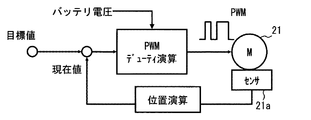
そこで制御部67は、図1に示すように、バッテリ25の電圧を取得する電圧取得手段として機能を有し、バッテリ電圧に応じて第2回路62および第5回路65を制御するためのデューティ比を決定する。以下、第1回路61〜第3回路63の制御と第4回路64〜第6回路66の制御は同様であるので、第1回路61〜第3回路63の制御を中心に説明する。
Therefore, as shown in FIG. 1, the
制御部67は、内外気切替ドア15または各吹出口切替ドア41a〜46aを所定の停止位置で停止するときには、停止位置に近づくにつれて、デューティ比が小さくなるように制御する。内外気切替ドア15の所定の停止位置は、たとえば内気導入口12を閉鎖する位置、および外気導入口13を閉鎖する位置である。また吹出口切替ドア41a〜46aの所定の停止位置は、各吹出モードに対応する位置である。このような位置に各ドアを配置する場合、停止位置に近づくと減速することによって、停止位置の位置決め精度の向上することができる。また各ドアの停止位置が空調ケース14に接触する位置である場合には、その停止時の接触による衝撃音などの騒音を低減することができる。
When the inside / outside
デューティ比は、図3に示す電圧指令マップによって決定される。電圧指令マップでは、偏差が小さくなるにつれて、減速するためにモータ駆動電圧を段階的に小さくしている。そして電圧指令マップでは、偏差が所定の下限値以下(図3では5以下)になると、モータ駆動電圧を最低作動電圧(図3では8V)未満にならないようにモータ駆動電圧が維持される。デューティ比は、図3に示す電圧指令マップによって決定されたモータ駆動電圧に基づいて決定される。 The duty ratio is determined by a voltage command map shown in FIG. In the voltage command map, the motor drive voltage is gradually reduced in order to decelerate as the deviation becomes smaller. In the voltage command map, when the deviation is equal to or less than a predetermined lower limit value (5 or less in FIG. 3), the motor drive voltage is maintained so that the motor drive voltage does not become less than the minimum operating voltage (8 V in FIG. 3). The duty ratio is determined based on the motor drive voltage determined by the voltage command map shown in FIG.
制御部67は、図4に示すように、目標値と現在値との偏差とバッテリ電圧と入力値として、図3に示す電圧指令マップを用いてPWMのためのデューティ比を決定する。そして決定したデューティ比を用いて各直流モータ21〜24を制御する。また各直流モータ21〜24に対応した各ポテンショメータ21a〜24aの出力信号から現在値を演算し、現在値をフィードバックする。
As shown in FIG. 4, the
次に、制御部67の処理について図5を用いて説明する。図5に示す処理は、制御部67の電源投入状態において実行される。ステップS1では、目標値と現在値との差の絶対値(偏差)が減速開始判定値よりも小さいか否かを判断し、小さい場合にはステップS2に移り、小さくなるまでステップS1の処理を繰り返す。
Next, the process of the
ステップS2では、偏差が減速開始判定値よりも小さいので、PWM駆動するためのデューティ比を演算し、ステップS3に移る。デューティ比の演算は、予め制御部67のメモリに記憶されている電圧指令マップが用いられる。偏差が小さくなるにつれて、モータ駆動電圧が小さくなるように、デューティ比が決定される。そして電圧指令マップでは、偏差が所定の下限値以下(図3で5以下)になると、モータ駆動電圧を最低作動電圧(図3では8V)未満にならないようにモータ駆動電圧が維持される。
In step S2, since the deviation is smaller than the deceleration start determination value, the duty ratio for PWM driving is calculated, and the process proceeds to step S3. For the calculation of the duty ratio, a voltage command map stored in advance in the memory of the
ステップS3では、デューティ比が決定されたので、決定されたデューティ比でPWM駆動し、ステップS4に移る。 In step S3, since the duty ratio is determined, PWM driving is performed with the determined duty ratio, and the process proceeds to step S4.
ステップS4では、目標値と現在値が一致したか否かが判断され、一致した場合には本フローを終了し、一致していない場合には、ステップS2に戻る。これによって一致するまでステップS2およびステップS3の処理が繰り返されることになる。 In step S4, it is determined whether or not the target value matches the current value. If they match, this flow ends. If they do not match, the process returns to step S2. As a result, steps S2 and S3 are repeated until they match.
このように制御部67は、偏差が減速開始判定値より小さくなると、PWM駆動を行って徐々に目標値に近づくように制御する。そして第1直流モータ21の最低作動電圧未満とならないように、デューティ比が決定されているので、第1直流モータ21の動作が不安定になることを防ぎつつ、停止精度の向上および騒音防止を達成することができる。
As described above, when the deviation becomes smaller than the deceleration start determination value, the
次に、第1直流モータ21の挙動に関して図6を用いて説明する。第1直流モータ21の偏差が減速開始判定値よりも小さくなる時刻t1からPWM駆動をする(図6参照)。そして最低作動電圧以上で徐々にデューティ比を小さくして、時刻t2にて目標値に到達する。時刻t2にて第1回路61のハイトラ61aおよびロートラ61bをオフにすることによって、第1直流モータ21は停止する。
Next, the behavior of the
デューティ比の変化は、バッテリ電圧によって異なり、バッテリ電圧が大きいとデューティ比は大きく変化し、バッテリ電圧が小さいとデューティ比は小さく変化する。たとえばバッテリ電圧が16Vの場合は、デューティ比の最低値は50%となり、バッテリ電圧が10Vのときはデューティ比の最低値は80%となり、バッテリ電圧が12Vのときはデューティ比の最低値は66%となる。 The change in the duty ratio varies depending on the battery voltage. When the battery voltage is high, the duty ratio changes greatly. When the battery voltage is low, the duty ratio changes small. For example, when the battery voltage is 16V, the minimum value of the duty ratio is 50%, when the battery voltage is 10V, the minimum value of the duty ratio is 80%, and when the battery voltage is 12V, the minimum value of the duty ratio is 66%. %.
次に、第1直流モータ21と第2直流モータ22とが同時に動作させる場合の各モータの挙動に関して図7および図8を用いて説明する。図7に示すように、第1直流モータ21の目標位置は、第2直流モータ22の目標位置よりも近い。したがってまず、第1直流モータ21の目標位置に到達するように2つのモータ21,22を同時に駆動し、第1直流モータ21を目標位置に到達させた後、第1直流モータ21を停止する。その後、第2直流モータ22だけを駆動して、第2直流モータ22の目標位置に到達するように制御する。
Next, the behavior of each motor when the
この場合、第1直流モータ21の偏差が減速開始判定値よりも小さくなる時刻T1からPWM駆動をする(図7参照)。第2回路62をPWM駆動するので、第2直流モータ22もPWM駆動されて減速する。そして最低作動電圧以上で徐々にデューティ比を小さくして、時刻T3にて目標値に到達する。そして時刻T3にて第1回路61のハイトラ61aおよびロートラ61bをオフにすることによって、第1直流モータ21は停止する。その後、第2直流モータ22の目標位置と現在位置から離れているので、100%のデューティ比となるように第2回路62を駆動する。
In this case, PWM driving is performed from time T1 when the deviation of the
従来ように最低作動電圧にかかわらず、単に減速する制御であると、図7および図8にて破線で示したように、時刻T2にて最低作動電圧を下回り、斜線で示した時間の動作が不安定になる。しかし本実施形態の制御部67は、前述のように第1直流モータ21と第2直流モータ22の最低作動電圧以上となるようにデューティ比が制御されているので、2つのモータ21,22の動作が不安定になることを防止することができる。
If the control is simply to decelerate regardless of the minimum operating voltage as in the prior art, as indicated by the broken line in FIGS. 7 and 8, the operation at the time indicated by the hatched line is below the minimum operating voltage at time T2. It becomes unstable. However, since the
以上説明したように本実施形態のモータ制御装置60の制御部67が第1回路61、第2回路62および第3回路63を制御して第1直流モータ21および第2直流モータ22を同時に回転させる際に、第2回路62を共用している。また制御部67が第4回路64、第5回路65および第6回路66を制御して第3直流モータ23および第4直流モータ24を同時に回転させる際に、第5回路65を共用している。このため、4つのモータを回転させるために、6つのハーフブリッジ回路を用いることになる。
As described above, the
1つの電動モータ毎に2つのハーフブリッジ回路(つまり、1つのフルブリッジ回路)を用いる場合には、4つの電動モータを回転させるために、8つのハーフブリッジ回路が必要になる。このため、本実施形態では、1つの電動モータ毎に2つのハーフブリッジ回路を用いる場合に比べて、ハーフブリッジ回路の使用個数を減らして、モータ制御装置60の回路構成を簡素化することができる。このため、モータ制御装置60のコストの低減を図ることができる。
When two half bridge circuits (that is, one full bridge circuit) are used for each electric motor, eight half bridge circuits are required to rotate the four electric motors. For this reason, in this embodiment, compared with the case where two half-bridge circuits are used for each electric motor, the number of half-bridge circuits used can be reduced and the circuit configuration of the
また制御部(制御手段)67は、共用する第2回路62の各スイッチ素子62a,62bをパルス幅変調方式で制御する。したがって共用する第2回路62の各スイッチ素子62a,62bのデューティ比を変化させることによって、第1直流モータ21と第2直流モータ22の駆動を高精度に制御することができる。そして制御部67は、取得した電圧に応じてデューティ比を変化させる。これによってバッテリ25の電圧の大小によってモータの動作が異なることを防ぐことができる。たとえば取得された電圧が所定値よりも低ければ、デューティ比を大きくして各モータを動作させるための電圧を確保することができる。また、たとえば取得された電圧が所定値よりも高ければ、デューティ比を小さくして各モータが設定以上に高速で動作することを防ぐことができる。したがってデューティ比を制御することによって、各モータを安定して動作させることができる。
The control unit (control means) 67 controls the
また本実施形態では、制御部67は、第1直流モータ21および第2直流モータ22の少なくともいずれか一方が駆動中におけるデューティ比の最小値を、各直流モータ21,22が動作する最低のデューティ比以上となるように設定する。このようにバッテリ電圧を考慮した電圧指令に基づきPWMデューティを決定することで、各モータ21,22の最低作動電圧を下回ることが無くなり、目標値前でモータ21,22が停止することを防ぐことができる。また対となってるモータ22も停止または過度な減速をすることなく駆動が可能となる。
In the present embodiment, the
さらに本実施形態では、制御部67は、内外気切替ドア15または吹出口切替ドア41a〜46aを所定の停止位置で停止するときには、停止位置に近づくにつれて、デューティ比が小さくなるように制御する。これによって停止位置に近づくにつれて、各ドアを減速することができる。したがって各ドアの停止位置の位置決め精度の向上することができる。また各ドアの停止位置が空調ケース14に接触する位置である場合には、その停止時の接触による衝撃音などの騒音を低減することができる。
Further, in the present embodiment, when the
このように本実施形態の制御部67は、バッテリ電圧を制御に用いて最低動作電圧相当のPWMデューティを下回らないようにPWM制御を行うことで、減速による効果と動作の安定化の効果を達成することができる。
As described above, the
(その他の実施形態)
以上、本発明の好ましい実施形態について説明したが、本発明は上述した実施形態に何ら制限されることなく、本発明の主旨を逸脱しない範囲において種々変形して実施することが可能である。
(Other embodiments)
The preferred embodiments of the present invention have been described above, but the present invention is not limited to the above-described embodiments, and various modifications can be made without departing from the spirit of the present invention.
上記実施形態の構造は、あくまで例示であって、本発明の範囲はこれらの記載の範囲に限定されるものではない。本発明の範囲は、特許請求の範囲の記載によって示され、さらに特許請求の範囲の記載と均等の意味及び範囲内での全ての変更を含むものである。 The structure of the said embodiment is an illustration to the last, Comprising: The scope of the present invention is not limited to the range of these description. The scope of the present invention is indicated by the description of the scope of claims, and further includes meanings equivalent to the description of the scope of claims and all modifications within the scope.
前述の第1実施形態では、バッテリ電圧値は、バッテリ25から直接取得しているがバッテリ25から直接取得する構成に限るものではない。たとえば、制御部67は、電子制御装置70からLIN通信でバッテリ電圧値を取得してもよい。また制御部67は、センサ信号からモータ駆動速度を算出して、モータ駆動速度に基づいてバッテリ電圧値を算出してもよい。
In the first embodiment described above, the battery voltage value is directly acquired from the
前述の第1実施形態では、電圧指令マップは1つであったが、1つに限るものではない。たとえば電子制御装置70でバッテリ電圧を監視し、バッテリ電圧に応じて電圧指令マップを適宜変更してもよい。
In the first embodiment described above, there is one voltage command map, but the number is not limited to one. For example, the battery voltage may be monitored by the
前述の第1実施形態では、第1ドアおよび第2ドアとして、エアミックスドア31a,31bとを用いる例、および内外気切替ドア15と吹出口切替ドア41a〜46aとを用いる例を示したが、これに限るものではない。運転席側通路34のエアミックスドア31aおよび助手席側通路35のエアミックスドア31b以外の2つのエアミックスドアを用いた車両用空調装置10において、2つのエアミックスドアを第1、第2のドアとしてもよい。
In the first embodiment described above, the example in which the
具体的には、空調ケース14内にてヒータコア18の上側に上側エアミックスドアを配置し、ヒータコア18の下側に下側エアミックスドアを配置して、各エアミックスドアを独立に駆動可能に構成された車両用空調装置10に適用してもよい。この場合、たとえば上側エアミックスドアを第1ドアとして、下側エアミックスドアを第2ドアとする。上側エアミックスドアは、例えば車室内前席側を空調するために用いられ、下側エアミックスドアは、例えば、車室内後席側を空調するために用いられる。
Specifically, an upper air mix door is arranged above the
また車室内の運転席側の吹出口切替ドア41a〜46aを駆動する第1モータと助手席側の吹出口切替ドア41a〜46aを駆動する第2モータとを備える車両用空調装置10に適用してもよい。この場合、たとえば運転席側の吹出口切替ドア41a〜43aを第1ドアとして、助手席側の吹出口切替ドア44a〜46aを第2ドアとする。
In addition, the present invention is applied to a
さらに車室内の前席側を空調するための前席用吹出口切替ドアを駆動する第1モータと車室内の後席側を空調するための後席用吹出口切替ドアを駆動する第2モータとを備える室内エアコンユニット11に適用してもよい。この場合、前席用吹出口切替ドアを第1ドアとして、後席用吹出口切替ドアを第2ドアとする。
Further, a first motor for driving a front seat outlet switching door for air conditioning the front seat side in the vehicle interior and a second motor for driving a rear seat outlet switching door for air conditioning the rear seat side in the passenger compartment. You may apply to the indoor air-
また前述の第1実施形態では、第1直流モータ21と第2直流モータ22の回転軸が同時に一方向に回転したときに、内気モードから外気モードに内外気モードが移行し、フェイスモードから順次、デフモードに吹出口モードが切り替わるようにした例を示した。しかしこれに限らず、第1直流モータ21と第2直流モータ22の回転軸が同時に一方向に回転したときに、外気モードから内気モードに移行し、フェイスモードから順次、デフモードの順に吹出口モードが切り替わるようにしてもよい。
In the first embodiment described above, when the rotating shafts of the
前述の第1実施形態では、空調装置として車両用空調装置10を用いた例を示したが、車両用に限るものではなく、住宅用空調装置、事務所用空調装置等の設置用空調装置を用いてもよい。また空調装置に限るものではなく、少なくとも2つのモータの駆動を制御するモータ制御装置であればよい。
In the first embodiment described above, an example in which the
12…内気導入口(第1通路) 13…外気導入口(第1通路) 15…内外気切替ドア(第1ドア) 21〜24…第1〜第4直流モータ(第1〜第4モータ) 25…バッテリ 31a…運転席側通路のエアミックスドア(第1ドア) 31b…助手席側通路のエアミックスドア(第2ドア) 34…運転席側通路(第1通路) 35…助手席側通路(第2通路) 41〜43…運転席側吹出口(第2通路) 41a〜43a…運転席側吹出口切換ドア(第2ドア) 44〜46…助手席側吹出口(第2通路) 44a〜46a…助手席側吹出口切換ドア(第2ドア) 60…モータ制御装置 61〜63…第1〜第3ハーフブリッジ回路 61a〜66a…ハイサイドトランジスタ(一対のスイッチ素子) 61b〜66b…ローサイドトランジスタ(一対のスイッチ素子) 64〜66…第4〜第6ハーフブリッジ回路(第1〜第3ハーフブリッジ回路) 67…制御部(制御手段、電圧取得手段)
12 ... Inside air introduction port (first passage) 13 ... Outside air introduction port (first passage) 15 ... Inside / outside air switching door (first door) 21-24 ... First to fourth DC motors (first to fourth motors) 25 ...
Claims (3)
バッテリ(25)のプラス端子とマイナス端子との間に直列接続される一対のスイッチ素子(61a〜66a,61b〜66b)をそれぞれ有している第1ハーフブリッジ回路(61,64)、第2ハーフブリッジ回路(62,65)および第3ハーフブリッジ回路(63,66)と、
前記バッテリの電圧を取得する電圧取得手段(67)と、
前記各ハーフブリッジ回路の前記各スイッチ素子を制御する制御手段であって、少なくとも前記第2ハーフブリッジ回路の各スイッチ素子をパルス幅変調方式で制御する制御手段(67)と、を含み、
前記第1ハーフブリッジ回路と前記第2ハーフブリッジ回路との間には前記第1モータが接続され、前記第2ハーフブリッジ回路と前記第3ハーフブリッジ回路との間には前記第2モータが接続され、
前記制御手段は、前記第1ハーフブリッジ回路および前記第2ハーフブリッジ回路を構成する4つのスイッチ素子を制御して前記第1ハーフブリッジ回路および前記第2ハーフブリッジ回路の間で前記第1モータに電流を流し、前記第2ハーフブリッジ回路および前記第3ハーフブリッジ回路を構成する4つのスイッチ素子を制御して前記第2ハーフブリッジ回路および前記第3ハーフブリッジ回路の間で前記第2モータに電流を流し、前記電圧取得手段によって取得された電圧に応じて、前記第2ハーフブリッジ回路の各スイッチ素子をパルス幅変調方式で制御するためのデューティ比を変化させ、
前記制御手段は、前記第1モータおよび前記第2モータの少なくともいずれか一方が駆動中における前記デューティ比の最小値を、前記第1モータおよび前記第2モータが駆動する最低のデューティ比以上となるように設定し、
前記制御手段は、前記第1モータおよび前記第2モータのいずれか一方のモータについて現在値が目標値となるように制御する場合には、前記目標値と前記現在値との差の絶対値が減速開始判定値よりも小さくなると、前記デューティ比を100%よりも小さく、かつ駆動する最低の前記デューティ比以上となるように制御し、前記現在値が前記目標値になると停止するように制御することを特徴とするモータ制御装置。 A motor control device (60) for controlling driving of the first motor (21, 23) and the second motor (22, 24),
A first half-bridge circuit (61, 64) having a pair of switch elements (61a to 66a, 61b to 66b) connected in series between a positive terminal and a negative terminal of the battery (25), and a second A half-bridge circuit (62, 65) and a third half-bridge circuit (63, 66);
Voltage acquisition means (67) for acquiring the voltage of the battery;
Control means for controlling the switch elements of the half-bridge circuits, and control means (67) for controlling at least the switch elements of the second half-bridge circuit by a pulse width modulation method,
The first motor is connected between the first half bridge circuit and the second half bridge circuit, and the second motor is connected between the second half bridge circuit and the third half bridge circuit. And
The control means controls the four switch elements constituting the first half bridge circuit and the second half bridge circuit to control the first motor between the first half bridge circuit and the second half bridge circuit. A current is supplied to control the four switch elements that constitute the second half bridge circuit and the third half bridge circuit, and a current is supplied to the second motor between the second half bridge circuit and the third half bridge circuit. In accordance with the voltage acquired by the voltage acquisition means, the duty ratio for controlling each switch element of the second half bridge circuit by a pulse width modulation method is changed ,
The control means has a minimum value of the duty ratio during driving of at least one of the first motor and the second motor equal to or higher than a minimum duty ratio driven by the first motor and the second motor. Set as
When the control means controls the current value to be a target value for one of the first motor and the second motor, the absolute value of the difference between the target value and the current value is When it becomes smaller than the deceleration start determination value, the duty ratio is controlled to be smaller than 100% and equal to or higher than the lowest driving duty ratio, and is controlled to stop when the current value becomes the target value. The motor control apparatus characterized by the above-mentioned.
前記第2モータは空気が流れる第2通路(35,41〜46)を開閉する第2ドア(31b,41a〜46a)を駆動し、
前記制御手段は、前記第1ドアまたは前記第2ドアを所定の停止位置で停止するときには、前記停止位置に近づくにつれて、前記デューティ比が小さくなるように制御することを特徴とする請求項2に記載のモータ制御装置。 The first motor drives a first door (15, 31a) that opens and closes a first passage (12, 13, 34) through which air flows,
The second motor drives second doors (31b, 41a to 46a) that open and close second passages (35, 41 to 46) through which air flows,
3. The control unit according to claim 2, wherein when the first door or the second door is stopped at a predetermined stop position, the control unit controls the duty ratio to become smaller as the stop position is approached. The motor control apparatus described.
Priority Applications (4)
| Application Number | Priority Date | Filing Date | Title |
|---|---|---|---|
| JP2013077847A JP6052028B2 (en) | 2013-04-03 | 2013-04-03 | Motor control device |
| PCT/JP2014/001779 WO2014162701A1 (en) | 2013-04-03 | 2014-03-27 | Motor controller |
| CN201480019715.XA CN105102248B (en) | 2013-04-03 | 2014-03-27 | Motor controller |
| US14/781,401 US9548683B2 (en) | 2013-04-03 | 2014-03-27 | Motor controller |
Applications Claiming Priority (1)
| Application Number | Priority Date | Filing Date | Title |
|---|---|---|---|
| JP2013077847A JP6052028B2 (en) | 2013-04-03 | 2013-04-03 | Motor control device |
Publications (3)
| Publication Number | Publication Date |
|---|---|
| JP2014201162A JP2014201162A (en) | 2014-10-27 |
| JP2014201162A5 JP2014201162A5 (en) | 2015-07-30 |
| JP6052028B2 true JP6052028B2 (en) | 2016-12-27 |
Family
ID=51658015
Family Applications (1)
| Application Number | Title | Priority Date | Filing Date |
|---|---|---|---|
| JP2013077847A Expired - Fee Related JP6052028B2 (en) | 2013-04-03 | 2013-04-03 | Motor control device |
Country Status (4)
| Country | Link |
|---|---|
| US (1) | US9548683B2 (en) |
| JP (1) | JP6052028B2 (en) |
| CN (1) | CN105102248B (en) |
| WO (1) | WO2014162701A1 (en) |
Families Citing this family (11)
| Publication number | Priority date | Publication date | Assignee | Title |
|---|---|---|---|---|
| JP6015607B2 (en) * | 2013-09-18 | 2016-10-26 | 株式会社デンソー | Air conditioning unit for vehicles |
| KR101628530B1 (en) * | 2014-11-17 | 2016-06-09 | 현대자동차주식회사 | Air conditioner for vehicle |
| CN106330008B (en) * | 2016-08-31 | 2019-09-20 | 惠州华阳通用电子有限公司 | A kind of on-board air conditioner motor control method and device |
| CN108331481A (en) * | 2018-02-28 | 2018-07-27 | 东方久乐汽车电子(上海)股份有限公司 | A kind of device that control rear tailgate opens and closes |
| DE102018208637B4 (en) * | 2018-05-30 | 2020-06-25 | Ford Global Technologies, Llc | Circuit for the selective control of DC motors in a motor vehicle |
| CN109586620A (en) * | 2018-12-06 | 2019-04-05 | 北京经纬恒润科技有限公司 | Multi objective control method, apparatus and multiple target drive control circuit |
| US11285557B2 (en) | 2019-02-05 | 2022-03-29 | Lincoln Global, Inc. | Dual wire welding or additive manufacturing system |
| JP7230674B2 (en) * | 2019-05-08 | 2023-03-01 | 株式会社デンソー | motor controller |
| DE102019211614A1 (en) * | 2019-08-02 | 2021-02-04 | Robert Bosch Gmbh | Method for protecting an electrical machine in a motor vehicle |
| KR102594072B1 (en) * | 2020-01-02 | 2023-10-24 | 세메스 주식회사 | Driving apparatus of semiconductor manufacturing equipment and driving method of semiconductor manufacturing equipment |
| WO2021195945A1 (en) * | 2020-03-31 | 2021-10-07 | 华为技术有限公司 | Multi-motor drive circuit and control method therefor |
Family Cites Families (27)
| Publication number | Priority date | Publication date | Assignee | Title |
|---|---|---|---|---|
| JPS565213A (en) * | 1979-06-22 | 1981-01-20 | Nippon Denso Co Ltd | Controlling method and system for car air conditioner |
| JPS56160213A (en) * | 1980-05-12 | 1981-12-09 | Nippon Denso Co Ltd | Air conditioning controller for automobile |
| US5199485A (en) * | 1990-08-03 | 1993-04-06 | Hitachi, Ltd. | Air conditioner for motor vehicle having right, left and center temperature controlled vents |
| JP3182773B2 (en) * | 1991-02-05 | 2001-07-03 | 株式会社デンソー | Automotive air conditioners |
| JP3161055B2 (en) * | 1992-07-15 | 2001-04-25 | 株式会社デンソー | Vehicle air conditioner |
| JP3596090B2 (en) * | 1995-06-06 | 2004-12-02 | 株式会社デンソー | Vehicle air conditioner |
| JPH0966736A (en) * | 1995-06-23 | 1997-03-11 | Denso Corp | Air conditioner for vehicle |
| JP4011816B2 (en) | 2000-02-17 | 2007-11-21 | アルプス電気株式会社 | Motor drive device |
| DE10253007A1 (en) * | 2002-11-14 | 2004-05-27 | Robert Bosch Gmbh | Electronic control system for two-motor drive for road vehicle windscreen wipers has three half-bridges in parallel, with the motors connected between adjacent pairs of bridges |
| JP2004208437A (en) * | 2002-12-26 | 2004-07-22 | Yamaha Livingtec Corp | Pump control device for air bubble bath |
| JP2004255921A (en) * | 2003-02-24 | 2004-09-16 | Denso Corp | Ventilation device for vehicle, and air-conditioner for vehicle |
| US20040232864A1 (en) | 2003-05-23 | 2004-11-25 | Hideki Sunaga | Apparatus for controlling motor |
| JP2004345558A (en) * | 2003-05-23 | 2004-12-09 | Calsonic Kansei Corp | Servo motor control device |
| JP4385678B2 (en) * | 2003-08-05 | 2009-12-16 | 株式会社デンソー | Battery cooling system for vehicles |
| JP2005059797A (en) * | 2003-08-19 | 2005-03-10 | Denso Corp | Air-conditioner for vehicle |
| JP4121475B2 (en) * | 2004-03-30 | 2008-07-23 | 三菱電機株式会社 | Power generation control device for vehicle generator |
| JP2006258076A (en) * | 2005-03-18 | 2006-09-28 | Aisin Seiki Co Ltd | Electric liquid pump, its control method and control device |
| JP2007295661A (en) * | 2006-04-21 | 2007-11-08 | Mitsuba Corp | Motor controller |
| JP4321594B2 (en) * | 2007-01-17 | 2009-08-26 | 株式会社デンソー | Air conditioner for vehicles |
| JP2009033834A (en) * | 2007-07-25 | 2009-02-12 | Tokai Rika Co Ltd | Load drive control circuit |
| JP4353304B2 (en) * | 2008-02-19 | 2009-10-28 | トヨタ自動車株式会社 | Motor drive control device |
| JP4450082B2 (en) * | 2008-03-10 | 2010-04-14 | トヨタ自動車株式会社 | Electric motor drive device and control method thereof |
| JP4947045B2 (en) * | 2008-12-19 | 2012-06-06 | トヨタ自動車株式会社 | Cooling device and vehicle equipped with the same |
| US8796967B2 (en) | 2010-06-08 | 2014-08-05 | Panasonic Corporation | Motor drive device, brushless motor, and motor drive method |
| JP2012121517A (en) * | 2010-12-10 | 2012-06-28 | Denso Corp | Control device for air conditioning apparatus |
| JP5370402B2 (en) * | 2011-03-28 | 2013-12-18 | 株式会社デンソー | Air conditioner for vehicles |
| US9371024B2 (en) * | 2012-02-13 | 2016-06-21 | Denso Corporation | Air-conditioner for vehicle |
-
2013
- 2013-04-03 JP JP2013077847A patent/JP6052028B2/en not_active Expired - Fee Related
-
2014
- 2014-03-27 US US14/781,401 patent/US9548683B2/en active Active
- 2014-03-27 CN CN201480019715.XA patent/CN105102248B/en not_active Expired - Fee Related
- 2014-03-27 WO PCT/JP2014/001779 patent/WO2014162701A1/en active Application Filing
Also Published As
| Publication number | Publication date |
|---|---|
| US9548683B2 (en) | 2017-01-17 |
| US20160043669A1 (en) | 2016-02-11 |
| CN105102248A (en) | 2015-11-25 |
| JP2014201162A (en) | 2014-10-27 |
| CN105102248B (en) | 2017-03-22 |
| WO2014162701A1 (en) | 2014-10-09 |
Similar Documents
| Publication | Publication Date | Title |
|---|---|---|
| JP6052028B2 (en) | Motor control device | |
| US10647176B2 (en) | Actuator control system | |
| WO2013065286A1 (en) | Control device for air conditioning device | |
| US6915650B2 (en) | Vehicle air conditioner with automatic control of main blower and sub-blower | |
| JP4596106B2 (en) | Air conditioner for vehicles | |
| JP3939642B2 (en) | Actuator drive controller | |
| JP5772726B2 (en) | Control unit for air conditioner | |
| JP2012121517A (en) | Control device for air conditioning apparatus | |
| JP5594274B2 (en) | Control device for air conditioner | |
| JP6048285B2 (en) | Motor control device | |
| JP5569506B2 (en) | Control device for air conditioner | |
| JP2007137342A (en) | Air conditioner for vehicle | |
| JP2002205532A (en) | Vehicular air-conditioner | |
| JP6221678B2 (en) | Air conditioner | |
| JP3979051B2 (en) | Air conditioner for vehicles | |
| JP2000238526A (en) | Air conditioner for vehicle | |
| JP2007161185A (en) | Link device and vehicular air conditioner | |
| JPH07309120A (en) | Motor actuator control device of air conditioner for automobile | |
| JP2005016344A (en) | Controller for vehicle | |
| JP2007137341A (en) | Air conditioner for vehicle | |
| KR19980019016U (en) | Rotary speed control device of blower motor by vehicle speed | |
| KR20050105802A (en) | Air-flow damper in airconditioning system for automobile and air-flow control method using the same | |
| JP2006076537A (en) | Vehicular air-conditioning system | |
| JP2010089533A (en) | Air conditioner for vehicle | |
| JPH0138684B2 (en) |
Legal Events
| Date | Code | Title | Description |
|---|---|---|---|
| A521 | Written amendment |
Free format text: JAPANESE INTERMEDIATE CODE: A523 Effective date: 20150610 |
|
| A621 | Written request for application examination |
Free format text: JAPANESE INTERMEDIATE CODE: A621 Effective date: 20150817 |
|
| TRDD | Decision of grant or rejection written | ||
| A01 | Written decision to grant a patent or to grant a registration (utility model) |
Free format text: JAPANESE INTERMEDIATE CODE: A01 Effective date: 20161101 |
|
| A61 | First payment of annual fees (during grant procedure) |
Free format text: JAPANESE INTERMEDIATE CODE: A61 Effective date: 20161114 |
|
| R151 | Written notification of patent or utility model registration |
Ref document number: 6052028 Country of ref document: JP Free format text: JAPANESE INTERMEDIATE CODE: R151 |
|
| R250 | Receipt of annual fees |
Free format text: JAPANESE INTERMEDIATE CODE: R250 |
|
| LAPS | Cancellation because of no payment of annual fees |