JP6037594B2 - Driving laser for EUV light source - Google Patents
Driving laser for EUV light source Download PDFInfo
- Publication number
- JP6037594B2 JP6037594B2 JP2009515472A JP2009515472A JP6037594B2 JP 6037594 B2 JP6037594 B2 JP 6037594B2 JP 2009515472 A JP2009515472 A JP 2009515472A JP 2009515472 A JP2009515472 A JP 2009515472A JP 6037594 B2 JP6037594 B2 JP 6037594B2
- Authority
- JP
- Japan
- Prior art keywords
- pulse
- amplifier
- gain medium
- laser
- energy
- Prior art date
- Legal status (The legal status is an assumption and is not a legal conclusion. Google has not performed a legal analysis and makes no representation as to the accuracy of the status listed.)
- Active
Links
- 239000002994 raw material Substances 0.000 claims description 11
- 239000000203 mixture Substances 0.000 claims description 9
- 230000002238 attenuated effect Effects 0.000 claims description 3
- 230000003321 amplification Effects 0.000 description 22
- 238000003199 nucleic acid amplification method Methods 0.000 description 22
- 230000036278 prepulse Effects 0.000 description 14
- 238000000034 method Methods 0.000 description 11
- ATJFFYVFTNAWJD-UHFFFAOYSA-N Tin Chemical compound [Sn] ATJFFYVFTNAWJD-UHFFFAOYSA-N 0.000 description 10
- 229920006395 saturated elastomer Polymers 0.000 description 10
- 230000002123 temporal effect Effects 0.000 description 10
- 239000000463 material Substances 0.000 description 9
- 230000005855 radiation Effects 0.000 description 8
- 238000002310 reflectometry Methods 0.000 description 7
- 230000003287 optical effect Effects 0.000 description 5
- 238000006243 chemical reaction Methods 0.000 description 4
- WHXSMMKQMYFTQS-UHFFFAOYSA-N Lithium Chemical compound [Li] WHXSMMKQMYFTQS-UHFFFAOYSA-N 0.000 description 3
- 238000010586 diagram Methods 0.000 description 3
- 230000005284 excitation Effects 0.000 description 3
- 229910052744 lithium Inorganic materials 0.000 description 3
- 238000000926 separation method Methods 0.000 description 3
- 229910052718 tin Inorganic materials 0.000 description 3
- 229910052724 xenon Inorganic materials 0.000 description 3
- FHNFHKCVQCLJFQ-UHFFFAOYSA-N xenon atom Chemical compound [Xe] FHNFHKCVQCLJFQ-UHFFFAOYSA-N 0.000 description 3
- PXGOKWXKJXAPGV-UHFFFAOYSA-N Fluorine Chemical compound FF PXGOKWXKJXAPGV-UHFFFAOYSA-N 0.000 description 2
- XUIMIQQOPSSXEZ-UHFFFAOYSA-N Silicon Chemical compound [Si] XUIMIQQOPSSXEZ-UHFFFAOYSA-N 0.000 description 2
- 238000001514 detection method Methods 0.000 description 2
- 238000006073 displacement reaction Methods 0.000 description 2
- 238000009826 distribution Methods 0.000 description 2
- 230000003993 interaction Effects 0.000 description 2
- 230000001678 irradiating effect Effects 0.000 description 2
- 239000007788 liquid Substances 0.000 description 2
- 238000012986 modification Methods 0.000 description 2
- 230000004048 modification Effects 0.000 description 2
- 238000005457 optimization Methods 0.000 description 2
- 239000000047 product Substances 0.000 description 2
- 238000005086 pumping Methods 0.000 description 2
- 230000009467 reduction Effects 0.000 description 2
- 229910052710 silicon Inorganic materials 0.000 description 2
- 239000010703 silicon Substances 0.000 description 2
- 239000000758 substrate Substances 0.000 description 2
- 239000013077 target material Substances 0.000 description 2
- ZOKXTWBITQBERF-UHFFFAOYSA-N Molybdenum Chemical compound [Mo] ZOKXTWBITQBERF-UHFFFAOYSA-N 0.000 description 1
- 230000009471 action Effects 0.000 description 1
- 230000003213 activating effect Effects 0.000 description 1
- 230000015572 biosynthetic process Effects 0.000 description 1
- 239000006227 byproduct Substances 0.000 description 1
- 230000008859 change Effects 0.000 description 1
- 230000000694 effects Effects 0.000 description 1
- 230000005670 electromagnetic radiation Effects 0.000 description 1
- 150000002500 ions Chemical class 0.000 description 1
- 238000001459 lithography Methods 0.000 description 1
- 238000004519 manufacturing process Methods 0.000 description 1
- 230000007246 mechanism Effects 0.000 description 1
- 239000011733 molybdenum Substances 0.000 description 1
- 229910052750 molybdenum Inorganic materials 0.000 description 1
- 238000001208 nuclear magnetic resonance pulse sequence Methods 0.000 description 1
- 239000002245 particle Substances 0.000 description 1
- 238000000206 photolithography Methods 0.000 description 1
- 230000008569 process Effects 0.000 description 1
- 230000004044 response Effects 0.000 description 1
- 238000007493 shaping process Methods 0.000 description 1
- 239000007787 solid Substances 0.000 description 1
Images


Classifications
-
- H—ELECTRICITY
- H01—ELECTRIC ELEMENTS
- H01S—DEVICES USING THE PROCESS OF LIGHT AMPLIFICATION BY STIMULATED EMISSION OF RADIATION [LASER] TO AMPLIFY OR GENERATE LIGHT; DEVICES USING STIMULATED EMISSION OF ELECTROMAGNETIC RADIATION IN WAVE RANGES OTHER THAN OPTICAL
- H01S3/00—Lasers, i.e. devices using stimulated emission of electromagnetic radiation in the infrared, visible or ultraviolet wave range
- H01S3/23—Arrangements of two or more lasers not provided for in groups H01S3/02 - H01S3/22, e.g. tandem arrangements of separate active media
- H01S3/2308—Amplifier arrangements, e.g. MOPA
- H01S3/2316—Cascaded amplifiers
-
- H—ELECTRICITY
- H05—ELECTRIC TECHNIQUES NOT OTHERWISE PROVIDED FOR
- H05G—X-RAY TECHNIQUE
- H05G1/00—X-ray apparatus involving X-ray tubes; Circuits therefor
- H05G1/08—Electrical details
- H05G1/26—Measuring, controlling or protecting
- H05G1/54—Protecting or lifetime prediction
-
- H—ELECTRICITY
- H05—ELECTRIC TECHNIQUES NOT OTHERWISE PROVIDED FOR
- H05G—X-RAY TECHNIQUE
- H05G2/00—Apparatus or processes specially adapted for producing X-rays, not involving X-ray tubes, e.g. involving generation of a plasma
- H05G2/001—X-ray radiation generated from plasma
- H05G2/008—X-ray radiation generated from plasma involving a beam of energy, e.g. laser or electron beam in the process of exciting the plasma
-
- H—ELECTRICITY
- H01—ELECTRIC ELEMENTS
- H01S—DEVICES USING THE PROCESS OF LIGHT AMPLIFICATION BY STIMULATED EMISSION OF RADIATION [LASER] TO AMPLIFY OR GENERATE LIGHT; DEVICES USING STIMULATED EMISSION OF ELECTROMAGNETIC RADIATION IN WAVE RANGES OTHER THAN OPTICAL
- H01S3/00—Lasers, i.e. devices using stimulated emission of electromagnetic radiation in the infrared, visible or ultraviolet wave range
- H01S3/005—Optical devices external to the laser cavity, specially adapted for lasers, e.g. for homogenisation of the beam or for manipulating laser pulses, e.g. pulse shaping
- H01S3/0057—Temporal shaping, e.g. pulse compression, frequency chirping
-
- H—ELECTRICITY
- H01—ELECTRIC ELEMENTS
- H01S—DEVICES USING THE PROCESS OF LIGHT AMPLIFICATION BY STIMULATED EMISSION OF RADIATION [LASER] TO AMPLIFY OR GENERATE LIGHT; DEVICES USING STIMULATED EMISSION OF ELECTROMAGNETIC RADIATION IN WAVE RANGES OTHER THAN OPTICAL
- H01S3/00—Lasers, i.e. devices using stimulated emission of electromagnetic radiation in the infrared, visible or ultraviolet wave range
- H01S3/14—Lasers, i.e. devices using stimulated emission of electromagnetic radiation in the infrared, visible or ultraviolet wave range characterised by the material used as the active medium
- H01S3/22—Gases
- H01S3/223—Gases the active gas being polyatomic, i.e. containing two or more atoms
- H01S3/2232—Carbon dioxide (CO2) or monoxide [CO]
-
- H—ELECTRICITY
- H01—ELECTRIC ELEMENTS
- H01S—DEVICES USING THE PROCESS OF LIGHT AMPLIFICATION BY STIMULATED EMISSION OF RADIATION [LASER] TO AMPLIFY OR GENERATE LIGHT; DEVICES USING STIMULATED EMISSION OF ELECTROMAGNETIC RADIATION IN WAVE RANGES OTHER THAN OPTICAL
- H01S3/00—Lasers, i.e. devices using stimulated emission of electromagnetic radiation in the infrared, visible or ultraviolet wave range
- H01S3/14—Lasers, i.e. devices using stimulated emission of electromagnetic radiation in the infrared, visible or ultraviolet wave range characterised by the material used as the active medium
- H01S3/22—Gases
- H01S3/223—Gases the active gas being polyatomic, i.e. containing two or more atoms
- H01S3/225—Gases the active gas being polyatomic, i.e. containing two or more atoms comprising an excimer or exciplex
Description
本出願は、2006年6月14日出願の米国特許出願出願番号第11/452、558号に対する優先権を請求するものである。本出願は、2006年2月21日出願の「プレパルスによるレーザ生成プラズマEUV光源」という名称の現在特許出願中の米国特許出願出願番号第11/358、988号、2005年8月9日にWebb他に付与された「長期遅延及び高TISパルス伸長器」という名称の米国特許第6、928、093号、2006年3月31日出願の「共焦点パルス伸長器」という名称の米国特許出願第11/394、512号(代理人整理番号第2004−0144−01号)、2005年5月26日出願の「線ビームとして整形されたレーザと基板上に堆積された膜の間の相互作用を実施するシステム及び方法」という名称の米国特許出願第11/138、001号(代理人整理番号第2004−0128−01号)、及び2002年5月7日出願の「ビーム送出を備えたレーザリソグラフィ光源」という名称の米国特許出願第10/141、216号で現在の米国特許第6、693、939号に関するものであり、これらの各々の開示内容は、本明細書において引用により組み込まれている。 This application claims priority to US patent application Ser. No. 11 / 452,558, filed Jun. 14, 2006. No. 11 / 358,988, filed Feb. 21, 2006, entitled “Laser Generated Plasma EUV Light Source by Prepulse”, published on Webb on Aug. 9, 2005. U.S. Patent No. 6,928,093 entitled "Long Delay and High TIS Pulse Stretcher", granted elsewhere, and U.S. Patent Application No. "Confocal Pulse Stretcher" filed March 31, 2006 11 / 394,512 (Attorney Docket No. 2004-0144-01), filed May 26, 2005 "Interaction between a laser shaped as a linear beam and a film deposited on a substrate. US Patent Application No. 11 / 138,001 (Attorney Docket No. 2004-0128-01) entitled "Systems and Methods to Implement" and issued May 7, 2002 US patent application Ser. No. 10 / 141,216, entitled “Laser Lithographic Light Source with Beam Delivery” of US Pat. No. 6,693,939, the disclosure of each of which is incorporated herein by reference. It is incorporated by reference in the description.
本発明は、極紫外線(EUV)光、例えば、約50nm及びそれ未満の波長の光を発生させるために、ターゲット材料の照射を含むがこれに限定されない用途に使用することができるレーザ光を発生させるためのシステム及び方法に関する。 The present invention generates extreme ultraviolet (EUV) light, for example, laser light that can be used in applications including, but not limited to, irradiation of target materials to generate light at wavelengths of about 50 nm and below. The present invention relates to a system and method.
極紫外線(EUV)光、例えば、約50nm又はそれ未満の波長(軟X線ということもある)を有し、13.5nm又は約13.5nmの波長の光を含む電磁放射線は、基板、例えば、シリコンウェーハ内に極めて小さな特徴部を生成するためにフォトリソグラフィ処理に使用することができる。 Extreme ultraviolet (EUV) light, such as electromagnetic radiation having a wavelength of about 50 nm or less (sometimes referred to as soft x-rays) and having a wavelength of 13.5 nm or about 13.5 nm, Can be used in photolithography processes to produce very small features in a silicon wafer.
EUV光を生成する方法は、以下に限定されるものではないが、輝線がEUV範囲にある元素、例えば、キセノン、リチウム、又はスズを有する材料をプラズマ状態に変換することを含む。多くの場合にレーザ生成プラズマ(LPP)と呼ばれる1つのこのような方法では、所要のプラズマは、所要の線放出元素を有する材料の小滴、流れ、又はクラスターのようなターゲット材料をレーザビームで照射することにより生成することができる。 A method for generating EUV light includes, but is not limited to, converting a material having an emission line in the EUV range, such as xenon, lithium, or tin, into a plasma state. In one such method, often referred to as a laser-produced plasma (LPP), the required plasma is driven by a laser beam through a target material such as a droplet, stream, or cluster of material having the required line-emitting element. It can be generated by irradiation.
LPP及び他の高電力レーザ用途では、特定のレーザ出力要件を満たすレーザ源が必要であることが多い。これらの要件としては、電力(又は、パルスレーザの場合、パルスエネルギ及び繰返し数)、パルス幅、ビーム品質、及び波長を含むことができる。一般的に、初期レーザコスト、レーザ運転コスト、信頼性及び変換効率(例えば、EUV電力出力と電気入力の比)を最適化することも望ましい。例えば、以下に限定されるものではないが、特定のLPP構成、例えば、スズターゲットを使用するは、波長10.6μm、パルス幅20〜150ns、及びパルスエネルギ約100mJの光を使用して効率的に作動させることができる。 LPP and other high power laser applications often require a laser source that meets specific laser power requirements. These requirements can include power (or pulse energy and repetition rate for pulsed lasers), pulse width, beam quality, and wavelength. In general, it is also desirable to optimize the initial laser cost, laser operating cost, reliability and conversion efficiency (eg, the ratio of EUV power output to electrical input). For example, but not limited to, using a specific LPP configuration, eg, a tin target, is efficient using light with a wavelength of 10.6 μm, a pulse width of 20-150 ns, and a pulse energy of about 100 mJ. Can be operated.
以上を踏まえて、本出願人は、上述の特性を有するレーザ光を効率的に生成するためのシステム及び方法を、他の指定のレーザ出力特性を生成するレーザ源の設計に拡張可能である本明細書に与える教示と共に開示する。 In light of the above, the present applicant is able to extend the system and method for efficiently generating laser light having the above characteristics to the design of laser sources that generate other specified laser output characteristics. It is disclosed with the teachings given in the specification.
実施形態の第1の態様では、レーザ光源は、出力ビームを生成するレーザ発振器と、出力ビームを増幅して第1の増幅ビームを生成する第1の増幅器と、第1の増幅ビームを増幅して第2の増幅ビームを生成する第2の増幅器とを含むことができる。この態様では、第1の増幅器は、飽和エネルギ(ES、1)及び小信号利得(go、1)により特徴付けられる利得媒体を有することができ、第2の増幅器は、(go、1)>(go、2)及び(Es、2)>(Es、1)である飽和エネルギ(Es、2)及び小信号利得(go、2)により特徴付けられる利得媒体を有することができる。レーザ光源は、第2の増幅ビームを増幅して第3の増幅ビームを生成する第3の増幅器を更に含むことができ、第3の増幅器は、g(o、1)>(go、2)>(go、3)及び(Es、3)>(Es、2)>(Es、1)である飽和エネルギ(Es、3)及び小信号利得(go、3)により特徴付けられる利得媒体を有する。 In the first aspect of the embodiment, the laser light source includes a laser oscillator that generates an output beam, a first amplifier that amplifies the output beam to generate a first amplified beam, and amplifies the first amplified beam. And a second amplifier for generating a second amplified beam. In this embodiment, the first amplifier can have a gain medium characterized by saturation energy (E S, 1) and a small signal gain (g o, 1), the second amplifier, (g o, 1)> (g o, 2 ) and (E s, 2)> a (E s, 1) a is saturated energy (E s, 2) and a gain medium characterized by a small signal gain (g o, 2) Can have. Laser light source, a third amplifier may further include a generating a third amplified beam to amplify the second amplified beam, the third amplifier, g (o, 1)> (g o, 2 )> the (g o, 3) and (E s, 3)> ( E s, 2)> (E s, 1) a is saturated energy (E s, 3) and a small signal gain (g o, 3) Having a gain medium characterized.
一実施形態では、第1の増幅器利得媒体は、第1のガス組成を有するガスを含むことができ、特定的な実施形態では、第2の増幅器利得媒体は、第1のガス組成と異なるガス組成を有するガスを含むことができる。一実施形態では、第1の増幅器利得媒体は、ガス圧P1のガスとすることができ、第2の増幅器利得媒体は、ガス圧P2のガスとすることができ、P1≠P2である。上述の実施形態のいずれに対しても、ガスは、CO2を含むことができる。 In one embodiment, the first amplifier gain medium can include a gas having a first gas composition, and in a particular embodiment, the second amplifier gain medium is a gas different from the first gas composition. A gas having a composition can be included. In one embodiment, the first amplifier gain medium can be a gas with a gas pressure P 1 and the second amplifier gain medium can be a gas with a gas pressure P 2 , where P 1 ≠ P 2. It is. For any of the above embodiments, the gas can include CO 2 .
レーザ光源の別の態様では、レーザ発振器は、例えば、モード固定レーザ発振器、q−スイッチレーザ発振器、又は他の空洞減衰レーザ発振器とすることができる。特定的な実施形態では、レーザ光源は、時間的パルス伸長器を更に含むことができる。1つの設定においては、時間的パルス伸長器は、発振器からレーザパルスを受け取って、そこから増幅器による増幅のために伸張パルスを生成するように位置決めされる。 In another aspect of the laser light source, the laser oscillator can be, for example, a mode-locked laser oscillator, a q-switched laser oscillator, or other cavity-attenuated laser oscillator. In particular embodiments, the laser light source can further include a temporal pulse stretcher. In one setting, a temporal pulse stretcher is positioned to receive a laser pulse from an oscillator and generate a stretch pulse therefrom for amplification by an amplifier.
実施形態の別の態様では、EUV光源は、EUV線放出元素を含有する小滴を生成する小滴発生器と、小滴を照射してEUV放射を生成するためのレーザ光源とを含むことができる。EUV光源に関しては、レーザ光源は、レーザパルスを生成するレーザ発振器と、レーザパルスを伸長する時間的パルス伸長器と、レーザパルスを増幅する増幅器とを含むことができる。特定的な実施形態では、増幅器は、パルスを増幅して第1の増幅ビームを生成する第1の増幅器とすることができ、第1の増幅器は、飽和エネルギ(Es、1)及び小信号利得(go、1)により特徴付けられる利得媒体を有し、EUV光源は、第1の増幅ビームを増幅して第2の増幅ビームを生成する第2の増幅器を更に含むことができ、第2の増幅器は、(go、1)>(go、2)及び(Es、2)>(Es、1)である飽和エネルギ(Es、2)及び小信号利得(go、2)により特徴付けられる利得媒体を有する。例えば、EUV線放出元素は、スズとすることができる。特定的な実施例では、レーザ発振器は、10〜30nsの範囲のパルス幅を有するレーザパルスを生成することができ、時間的パルス伸長器は、50〜150nsの範囲のパルス幅を有するレーザパルスを生成することができる。 In another aspect of the embodiment, the EUV light source may include a droplet generator that generates a droplet containing an EUV radiation emitting element and a laser light source for irradiating the droplet to generate EUV radiation. it can. With respect to an EUV light source, the laser light source can include a laser oscillator that generates a laser pulse, a temporal pulse stretcher that stretches the laser pulse, and an amplifier that amplifies the laser pulse. In a particular embodiment, the amplifier may be a first amplifier that amplifies the pulse to produce a first amplified beam, the first amplifier comprising saturation energy (E s , 1 ) and a small signal has a gain medium characterized by a gain (g o, 1), EUV light source may further comprise a second amplifier for generating a second amplified beam by amplifying the first amplified beam, the 2 of amplifier, (g o, 1)> (g o, 2) and (E s, 2)> ( E s, 1) a is saturated energy (E s, 2) and a small signal gain (g o, 2 ) Having a gain medium characterized by For example, the EUV radiation emitting element can be tin. In a particular embodiment, the laser oscillator can generate a laser pulse having a pulse width in the range of 10-30 ns, and the temporal pulse stretcher can generate a laser pulse having a pulse width in the range of 50-150 ns. Can be generated.
実施形態の態様はまた、シードレーザビームを生成する段及び/又は段階と、飽和エネルギ(Es、1)及び小信号利得(go、1)により特徴付けられる第1の利得媒体を使用してシードビームを増幅し、第1の増幅ビームを生成する段及び/又は段階と、(go、1)>(go、2)及び(Es、2)>(Es、1)である飽和エネルギ(Es、2)及び小信号利得(go、2)により特徴付けられる利得媒体を有する第2の利得媒体を使用して第1の増幅ビームを増幅し、第2の増幅ビームを生成する段及び/又は段階とを含むレーザ光を発生させる方法を含むことができる。 Aspects of the embodiments may also use the stage and / or stage to produce a seed laser beam, the first gain medium characterized by saturation energy (E s, 1) and a small signal gain (g o, 1) a stage and / or stage seed beam amplified to generate a first amplified beam Te, in (g o, 1)> ( g o, 2) and (E s, 2)> ( E s, 1) there saturated energy (E s, 2) and a small signal gain (g o, 2) by using a second gain medium having a gain medium characterized by amplifying the first amplified beam, a second amplification beam And / or a step of generating a laser beam including a step.
本発明の実施形態の更に別の態様は、EUV線放出元素、例えば、スズを含有する材料と、少なくとも1つのレーザパルスの供給源、例えば、CO2レーザと、少なくとも3つのピークを有するようにパルスの形状を修正するパルス伸長器とを有するEUV光源を含み、伸長器が、ピークの相対マグニチュードを定めるビームスプリッタ及びピークの時間的分離を確立する遅延経路を有し、修正パルス形状が、材料を照射し、パルス伸長器がない場合に発生するEUV強度よりも大きいEUV強度を生成するように選択されるとして特徴付けることができる。一実施形態では、修正ビームの第1のピークは、修正ビームの別のピークよりも低い強度を有し、特定的な実施形態では、第1のピークの1つ又はそれよりも多くのパラメータは、プレパルスで材料を照射し、第2のピークによるその後の照射に向けて線放出元素を空間的に拡張させるように選択される。一構成においては、パルス伸長器は、非変位式パルス伸長器とすることができ、特定の構成においては、パルス伸長器は、伸長器を出る異なる経路上に各パルスピークを置くことができ、材料は、小滴の形態とすることができる。 Yet another aspect of embodiments of the present invention is to have a material containing an EUV radiation emitting element, such as tin, at least one laser pulse source, such as a CO 2 laser, and at least three peaks. An EUV light source having a pulse stretcher that modifies the shape of the pulse, the stretcher having a beam splitter that defines the relative magnitude of the peak and a delay path that establishes the temporal separation of the peak, And selected to produce an EUV intensity that is greater than the EUV intensity generated in the absence of a pulse stretcher. In one embodiment, the first peak of the modified beam has a lower intensity than another peak of the modified beam, and in a particular embodiment, one or more parameters of the first peak are , Irradiating the material with a pre-pulse and choosing to spatially expand the line emitting element for subsequent irradiation by the second peak. In one configuration, the pulse stretcher can be a non-displacement pulse stretcher, and in a particular configuration, the pulse stretcher can place each pulse peak on a different path exiting the stretcher, The material can be in the form of droplets.
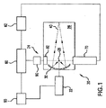
最初に図1を参照すると、本発明の一態様による例示的なEUV光源、例えば、レーザ生成プラズマEUV光源20の概略図が示されている。図1に示し、かつ以下でより詳細に説明するように、LPP光源20は、光パルスを生成して、チャンバ26内に光パルスを送出する供給源22を含むことができる。以下で詳細するように、光パルスは、供給源22からから1つ又はそれよりも多くのビーム経路に沿って、かつチャンバ26内に進んで1つ又はそれよりも多くのターゲット容積を照明することができる。
Referring initially to FIG. 1, a schematic diagram of an exemplary EUV light source, eg, a laser-produced plasma
図1に更に示すように、光源20は、例えば、ターゲット容積28までチャンバ26の内部に原材料の小滴を送出する原材料送出システム24を含むことができ、チャンバ26で、原材料ターゲットは、プラズマを生成してEUV放射を生成するために1つ又はそれよりも多くの光パルス、例えば、プレパルス、次に、主要パルスにより照射されることになる。原材料としては、スズ、リチウム、キセノン、又はその組合せを含む材料を含むことができるが、これに限定されるものではない。EUV放射元素、例えば、スズ、リチウム、キセノンなどは、液体小滴、及び/又は液体小滴内に含有された固体粒子、又はEUV放射元素をターゲット容積に供給するあらゆる他の形態とすることができる。
As further shown in FIG. 1, the
引き続き図1を用いて、光源20は、供給源22により生成された光パルスがターゲット容積28を通過し、かつターゲット容積28に到達することを可能にする開口を有する、例えば、長軸に対して直角に切断された楕円の形態の収集器30、例えば、反射体、例えば、モリブデン及びシリコンの交互層を有する多層ミラーを含むことができる。収集器30は、例えば、ターゲット容積28内又はその近くに第1の焦点、及びEUV光を光源20から出力して、例えば、集積回路リソグラフィツール(図示せず)に入力することができるいわゆる中間点40(中間焦点40とも呼ばれる)に第2の焦点を有する楕円ミラーとすることができる。
With continued reference to FIG. 1, the
光源20は、EUV光源制御システム60を含むことができ、EUV光源制御システム60は、供給源22内の1つ又はそれよりも多くのランプ及び/又はレーザ源を起動させることによりチャンバ26に送出のための光パルスを生成する発射制御システム65を含むことができる。光源20はまた、小滴位置検知システムを含むことができ、小滴位置検知システムは、例えば、ターゲット容積28に対して1つ又はそれよりも多くの小滴の位置を示す出力を供給する1つ又はそれよりも多くの小滴撮像装置70を含み、かつこの出力を小滴位置検出フィードバックシステム62に供給することができ、これは、例えば、小滴単位で又は平均して、小滴誤差を計算することができる例えば小滴位置及び軌道を計算することができる。小滴誤差は、次に、光源コントローラ60への入力として供給することができ、光源コントローラ60は、例えば、位置、方向、及びタイミング補正信号を供給源22に供給して供給源タイミング回路を制御し、及び/又は例えばチャンバ26に送出されている光パルスの位置及び/又は焦点屈折力を変えるようにビーム位置及び整形システムを制御することができる。
The
図1に示すように、光源20は、例えば、望ましいターゲット容積28に到着する小滴内の誤差を補正するように小滴送出機構92からの原材料の放出点を修正するために、システムコントローラ60からの信号(一部の実施例では、上述の小滴誤差又はそこから導出した何らかの量を含むことができる)に応答して作動可能な小滴送出制御システム90を含むことができる。
As shown in FIG. 1, the
図2は、発振器ユニット200及び増幅ユニット202を含む供給源22の一実施形態を示している。例えば、発振器ユニット200は、パルスガス放電CO2、エキシマ又は分子フッ素レーザ発振器を含むことができ、増幅ユニット202は、発振器又は単一/二重通過増幅器として構成された1つ又はそれよりも多くのガス放電CO2、エキシマ又は分子フッ素レーザユニットを含むことができる。増幅ユニット202内のレーザユニットは、並列又は直列に配置することができる。
FIG. 2 illustrates one embodiment of a
図3は、発振器ユニット200’、時間的パルス伸長器300、及び増幅ユニット202’を含む供給源22’の別の実施形態を示している。時間的パルス伸長器に関するより多くの詳細は、2005年8月9日にWebb他に付与された「長期遅延及び高TISパルス伸長器」という名称の米国特許第6、928、093号、2006年3月31日出願の「共焦点パルス伸長器」という名称の米国特許出願第11/394、512号(代理人整理番号第2004−0144−01号)、2005年5月26日出願の「線ビームとして整形されたレーザと基板上に堆積された膜の間での相互作用を実施するシステム及び方法」という名称の米国特許出願第11/138、001号(代理人整理番号第2004−0128−01号)、及び2002年5月7日出願の「ビーム送出を備えたレーザリソグラフィ光源」という名称の米国特許出願第10/141、216号で現在の米国特許第6、693、939号に見ることができ、これらの各々の開示内容は、本明細書において引用により組み込まれている。一般的に、これらの光学パルス伸長器は、遅延経路304に沿って一部のビームを通過させるビームスプリッタ302を含み、適切なビームスプリッタ反射率及び遅延ビーム路長を選択することにより、伸長器を出るパルス形状を制御することができる。具体的には、パルス伸長器300は、単一ピーク(すなわち、強度と時間のプロットにおいて)を通常有する入力パルスを受光し、複数の時間的に離間したピークを有するパルスを出力する。図示のように、伸長器300は、実質的に無損失性とすることができる。パルスピークが共通のビーム経路で全て出力される場合に対しては、パルス伸長器は、本明細書では非変位パルス伸長器と呼ぶ。図3に示す配置に対しては、伸長器300の構成要素は、パルス伸長器が非変位であるように整列させることができる。
FIG. 3 shows another embodiment of a source 22 'that includes an oscillator unit 200', a
伸長器に関しては、ビームスプリッタの反射率は、出力ピークの相対マグニチュードに影響を与えることになり、遅延経路の長さは、ピーク間の時間的分離を確立することができる。従って、出力パルス形状は、ビームスプリッタ反射率の適切な選択及び遅延経路の長さにより設計することができる。 For the stretcher, the reflectivity of the beam splitter will affect the relative magnitude of the output peaks, and the length of the delay path can establish temporal separation between the peaks. Thus, the output pulse shape can be designed with an appropriate choice of beam splitter reflectivity and delay path length.
更に、一部の場合には、出力パルス形状は、EUV出力及び/又は変換効率(すなわち、出力EUV電力とEUV光源入力電力の比)を増大し、及び/又は原材料の消費量、例えば、スズ消費量を低減し、及び/又は様々なプラズマチャンバ光学要素、例えば、ミラー、ウィンドなど)の作動効率を潜在的に損なうか又は低減する可能性があるプラズマチャンバ内での好ましくない副産物(例えば、デブリ)の形成を低減するように最適化することができる。 Further, in some cases, the output pulse shape increases EUV output and / or conversion efficiency (ie, the ratio of output EUV power to EUV light source input power) and / or raw material consumption, eg, tin Undesirable by-products in the plasma chamber (e.g., which can reduce consumption and / or potentially compromise or reduce the operational efficiency of various plasma chamber optical elements, e.g., mirrors, windows, etc.) It can be optimized to reduce the formation of debris.
一部の用途に最適とすることができる1つの特定のパルス形状は、図3A及び図3Bに示すように、プレパルスピーク、及びそれに続くより強い主パルスピークを含む。より詳細には、図3Aは、パルス伸長器を出るパルス310の形状を示しており、ビームスプリッタの反射率は、第2のピーク312の強度が第1のピーク314よりも増大するように選択され、遅延経路長は、最初の2つのピークが時間t1によって分離されるように選択されたものである。ピーク312に対応する尾部は、そのピークに対応する尾部と重複し、従って、2つのピークは同じパルスの一部であることは認められるものとする。例示する目的で、図3Bは、パルス伸長器を出るパルス’の形状を示しており、ビームスプリッタの反射率は、図3Aに対応するビームスプリッタとほぼ同じであり、従って、第2のピーク312’は、強度が第1のピーク314’よりも大きいが、第1のピーク314’よりも長い遅延経路長を使用しており、この時点で、2つのピークは、時間t2により分離され、t2>t1である。それに反して、図3Cは、同じく例示する目的で、パルス伸長器を出るパルス310’’に対する形状を示しており、ビームスプリッタの反射率は、図3Aに対応するビームスプリッタを下回り、従って、第2のピーク312’’は、強度が第1のピーク314’’よりも小さい。尚、パルス310’’の遅延経路長は、結果としてピークの分離時間t3になるパルス310の遅延経路長とほぼ同じであり、t3=t1である。従って、図3Aは、ビームスプリッタ反射率及び遅延ビーム路長を変えることにより、広い範囲のパルス形状を生成することができることを示している。
One particular pulse shape that may be optimal for some applications includes a pre-pulse peak followed by a stronger main pulse peak, as shown in FIGS. 3A and 3B. More specifically, FIG. 3A shows the shape of the
EUV電力及び/又は変換効率を増大させ、及び/又は消費/デブリを低減するプレパルスの使用の詳細は、代理人整理番号第2005−0085−01号である2006年2月21日出願の「プレパルスによるレーザ生成プラズマEUV光源」という名称の現在特許出願中の米国特許出願出願番号第11/358、988号に見ることができ、この特許の開示内容は、本明細書において引用により組み込まれている。一部の場合には、プレパルスピークを使用して原材料、例えば、スズ滴を蒸発させて空間的に拡張し、その後の主パルスを使用して、拡張原材料からEUV放射を生成することができる。 Details of the use of prepulses to increase EUV power and / or conversion efficiency and / or reduce consumption / debris can be found in “Prepulse” filed on Feb. 21, 2006, attorney docket number 2005-0085-01. In US patent application Ser. No. 11 / 358,988, entitled “Laser-produced plasma EUV light source”, the disclosure of which is incorporated herein by reference. . In some cases, a prepulse peak can be used to evaporate a raw material, eg, a tin drop, to spatially expand and a subsequent main pulse can be used to generate EUV radiation from the expanded raw material.
プレパルスピークのマグニチュードによっては、原材料は、一部の実施例では、弱いプラズマを形成することができる。本明細書で使用する時、用語「弱いプラズマ」及びその派生語は、イオンを含むが約1%未満が電離された材料を意味する。予め選択した時間が、プレパルスピークでの照射後に経過した後、照射された材料を主パルスピークプラズマに露光させてEUV放射を作り出すことができる。例えば、COレーザ源及びスズ滴に対しては、1〜10mJプレパルス及び50〜400mJの主パルスが適切とすることができる。 Depending on the magnitude of the prepulse peak, the raw material can form a weak plasma in some embodiments. As used herein, the term “weak plasma” and its derivatives refer to materials that contain ions but are less than about 1% ionized. After a preselected time has elapsed after irradiation at the prepulse peak, the irradiated material can be exposed to the main pulse peak plasma to create EUV radiation. For example, a 1-10 mJ prepulse and a 50-400 mJ main pulse may be appropriate for a CO laser source and tin drops.
上述のように、図3に示す伸長器300の構成要素は、パルス伸長器が非変位であるように整列させることができる。代替的に、図3Dに示すように、各連続パルスピークが僅かに異なる経路に沿って誘導されるようにパルス伸長器300’を製造するために、光学構成要素(すなわち、遅延路304’を定めるビームスプリッタ302’又はミラー)の1つ又はそれよりも多くのアラインメントの僅かな変更を行うことができる。特に、伸長器300に対しては、第1のパルスピークは、経路320に沿って放出することができ、第2のパルスピークは、経路322に沿って放出することができ、第3のパルスピークは、経路324に沿って放出することができ、第4のパルスピークは、経路326に沿って放出することができる等々である。この構成では、パルスの連続は、方向330における移動で示すように、移動中の材料328、例えば、小滴又はプレパルス容積に「追随」することができる。
As described above, the components of the
図3に示す構造に対しては、発振器ユニット200’は、レーザ発振器、例えば、モード固定レーザ発振器、q−スイッチレーザ発振器、又は他の空洞減衰レーザ発振器を含むことができる。レーザ発振器は、その後にパルス伸長器を使用して増大させる所望よりも短い例えば10〜30nsの範囲のパルス幅を供給することができる。一部のLPP構成に対しては、短パルス幅は、EUV光源の変換効率(すなわち、EUV出力と原材料/レーザ入力の比)を制限する場合がある。例えば、一部のCO2放射線のためのパルス増幅器に対しては、長パルスの増幅は、CO2モジュールの同じ振動帯域の回転線間のエネルギ交換のために短(10ns範囲)パルスの場合よりも効率的である。長パルスの使用は、プレパルスの複雑さを回避することができる。例えば、スズ滴を使用する一部のLPP構成に対しては、適切なパルス幅は、約20〜180ns、恐らくは50〜150nsの範囲とすることができる。伸長器300の使用には、プレパルスがパルス伸長器300を通過又は迂回する状態でプレパルスが使用される構成への用途もあると考えられる。
For the structure shown in FIG. 3, the
図3に示す設定に対しては、時間的パルス伸長器300は、発振器ユニット200からレーザパルスを受光して、増幅ユニット202によるその後の増幅に向けて伸長パルスを生成するように位置決めされる。この構成は、増幅ユニット202の前にピークのパルス強度を下げ、高強度による増幅ユニット光学要素の損傷を低減する。他の配置も可能であり、例えば、パルス伸長器は、増幅ユニット202’内のレーザユニットの1つ、一部、又は全ての後に位置決めすることができる。
For the setting shown in FIG. 3, the
図4は、図2又は図3の実施形態における使用に適する直列に配置された2つの増幅器400、402を有する増幅ユニット202a、202a’の例を示している。増幅ユニット202a、202aに対しては、増幅器400は、利得媒体長(L1)、飽和エネルギ(Es、1)、及び小信号利得(go、1)により特徴付けられる利得媒体を有することができ、増幅器402は、利得媒体長(L2)、飽和エネルギ(Es、2)、及び小信号利得(go、2)により特徴付けられる利得媒体を有することができる。
FIG. 4 shows an example of an amplification unit 202a, 202a ′ having two
本明細書で使用する時、用語「飽和エネルギ」及びその派生語は、利得媒体の利得のその初期値の1/e(≒37%)までの低減をもたらす入力信号パルスのパルスエネルギを意味する。 As used herein, the term “saturation energy” and its derivatives mean the pulse energy of an input signal pulse that results in a reduction of the gain medium gain to 1 / e (≈37%) of its initial value. .
本明細書で使用する時、用語「小信号利得」及びその派生語は、利得媒体のいかなる認められるほどの利得飽和も引き起こさないほど弱い入力信号に対して得られる利得を意味する。 As used herein, the term “small signal gain” and its derivatives refer to gain obtained for input signals that are weak enough not to cause any appreciable gain saturation of the gain medium.
上記で意味するように、(go、1)>(go、2)及び(Es、2)>(Es、1)で増幅器400、402の利得媒体を構成することができる。以下で更に詳述するように、この構成により、結果として、L1+L2の利得媒体長を有する単一増幅器よりも大きな増幅にすることができる。この影響は、図5により例示されており、図5は、比較的高い小信号利得(go=0.9m-1)及び比較的低い飽和エネルギ(Es=5mJ)を有するL=8mの利得媒体のEin対Eoutの曲線500、比較的低い小信号利得(go=0.5m-1)及び比較的高い飽和エネルギ(Es=25mJ)を有するL=8mの利得媒体のEin対Eoutの曲線502、第1の増幅器が比較的高い小信号利得(go=0.9m-1)及び比較的低い飽和エネルギ(Es=5mJ)を有し、第2の増幅器が比較的低い小信号利得(go=0.5m-1)及び比較的高い飽和エネルギ(Es=25mJ)を有する総利得媒体長L1+L2=8mの一連の2つの増幅器に対するEout対Einの曲線504を示している。図示の利得パラメータは、CO2レーザの典型的な値である。2つの増幅器による構成(曲線504)により、結果として、単一増幅器による構成(曲線500、502)のいずれかよりも高いEoutになる重要な領域(すなわち、Ein>0.25mJ)になることを見ることができる。特に、Ein=1mJでは、2つの増幅器による構成は、一定のパラメータを有する単一の増幅器に対するものをほぼ全長にわたってほぼ50%超える出力エネルギを有する。従って、同じ利得媒体長、すなわち、L=8mの場合、2つの増幅器による構成(曲線504)により、結果として単一増幅器による構成(曲線500、502)のいずれかよりも高いEoutになる。
To mean above, can be configured (g o, 1)> ( g o, 2) and (E s, 2)> gain medium (E s, 1) by the
数学的には、PA(Eout)の出力エネルギと入力エネルギ(Ein)の比率は、利得媒体の2つのパラメータ、すなわち、小信号利得(go)x媒体長(l)、及び飽和エネルギ(Es)レベルによって定められる。Frantz−Nodvic公式によると、以下の通りであり、例えば、L.M.Frantz、J.S.Nodvik、「J.Appl.Phys.」、34、2346(1963年)を参照されたい。 Mathematically, the ratio of PA output energy and input energy (E out) (E in) is, two parameters of the gain medium, i.e., the small signal gain (g o) x medium length (l), and saturated energy Determined by (E s ) level. According to the Francz-Nodvic formula, it is as follows. M.M. Franz, J. et al. S. See Nodvik, “J. Appl. Phys.”, 34, 2346 (1963).

CO2レーザ増幅器のようなRF、DC、又はパルス励起ガス放電媒体に対しては、これらのパラメータは、独立したものではない。例えば、RF励起利得媒体においては、低いRFポンピング電力及び低圧を使用して高いgoを取得することができ、一方、同じ媒体に対してEsを増大させるためには、対応するgoの低減によって高いRF電力及び高いガス圧を使用することができる。Frantz−Nodvik公式の対象外であり、同じくgo及びEsに影響を与える別のパラメータは、レーザ媒体のガス混合物(例えば、CO2:N2の比率:He)である。従って、RF電力、ガス圧、ガス組成、及びガスポンピング速度を含むいくつかの利得媒体因子は、小信号利得(go)x媒体長(l)、及び飽和エネルギ(Es)を選択的に定めるように制御することができる。パルス幅及び形状、強度分布、例えば、ガウス分布のような入力ビーム特性は、小信号利得(go)及び飽和エネルギ(Es)を取得するのに必要なパラメータ、例えば、圧力、組成、及び励起電圧の選択にも影響を及ぼす場合がある。 For RF, DC, or pulsed excitation gas discharge media such as CO2 laser amplifiers, these parameters are not independent. For example, in the RF excitation gain medium, it is possible to obtain a high g o using low RF pumping power and low pressure, whereas, in order to increase the E s for the same medium, the corresponding g o Reduction can use high RF power and high gas pressure. Frantz-Nodvik is outside the official target, also another parameter which affects the go and E s, the gas mixture of the laser medium (e.g., CO 2: the ratio of N 2: He) is. Thus, RF power, gas pressure, gas composition, and some of the gain medium factors including gas pumping rate, the small signal gain (g o) x medium length (l), and optionally a saturated energy (E s) Can be controlled as determined. Pulse width and shape, intensity distribution, for example, the input beam characteristics, such as a Gaussian distribution parameters needed to obtain the small signal gain (g o) and saturated energy (E s), for example, pressure, composition, and It may also affect the choice of excitation voltage.
飽和エネルギに対する小さな入力エネルギ(すなわち、Ein/Es<<1、及びEin/Es<<exp(g0 *l))に対しては、公式(1)は、以下によって近似することができる。 For small input energies relative to saturation energy (ie, E in / E s << 1 and E in / E s «exp (g 0 * l)), formula (1) is approximated by Can do.
![]()
![]()
これは、小さな入力信号のレーザ出力エネルギが飽和エネルギに依存するのではなく、指数的に(g0l)の積に依存することを意味する。出力エネルギは、入力エネルギと線形に比例する。Ein〜Es時の高い入力エネルギに対しては、Esに対する依存性はより有意になる。この場合に対しては、公式(1)内の両括弧内の「1」を無視して以下の式を得ることができる。 This means that the laser output energy of a small input signal does not depend on the saturation energy, but exponentially depends on the product of (g 0 l). The output energy is linearly proportional to the input energy. For high input energy at the time of E in ~E s, dependence becomes more significant for the E s. In this case, the following formula can be obtained by ignoring “1” in both parentheses in the formula (1).
![]()
![]()
一般的に長い利得媒体に有効であるEin/Es<g0lの時に、公式(3)の第2項を無視して以下の式を得ることができる。 When E in / E s <g 0 l which is generally effective for a long gain medium, the following equation can be obtained by ignoring the second term of the formula (3).
![]()
![]()
この式は、出力エネルギが、入力エネルギに依存しない飽和値に達することを示している。より高いEinに対しては、出力エネルギは、何らかのオフセットがあり、かつEinの場合よりも小さい傾斜で入力エネルギと共に線形に変化する。 This equation shows that the output energy reaches a saturation value independent of the input energy. For higher E in, output energy, there is some offset, and varies linearly with input energy with a smaller inclination than for E in.
図6に示すように、上記で展開した原理は、3つ又はそれよりも多くの増幅器に拡張することができる。より具体的には、図6は、図2又は図3の実施形態のいずれかでの使用に適する直列に配置された3つの増幅器600、602、604を有する増幅ユニット202b、202b’の例を示している。図示の増幅ユニット202b、202b’に対しては、増幅器600は、利得媒体長(L1)、飽和エネルギ(Es、1)、及び小信号利得(go、1)により特徴付けられる利得媒体を有することができ、増幅器602は、利得媒体長(L2)、飽和エネルギ(Es、2)、及び小信号利得(go、2)により特徴付けられる利得媒体を有することができ、増幅器604は、(go、1)>(go、2)>(go、3)及び(Es、3)>(Es、2)>(Es、1)である利得媒体長(L3)、飽和エネルギ(Es、3)、及び小信号利得(go、3)により特徴付けられる利得媒体を有することができる。上述のように、この構成により、結果としてL1+L2+L3の利得媒体長を有する単一増幅器よりも大きな増幅をもたらすことができる。
As shown in FIG. 6, the principles developed above can be extended to three or more amplifiers. More specifically, FIG. 6 shows an example of an
所定の入力エネルギでの全体的な出力電力(又は、出力パルスエネルギ)の最適化のために、同等長の単一増幅器の代わりに複数の独特に構成した増幅器を使用することができる。1つの特定的な実施例では、第1の増幅器は、利用可能な最大g0パラメータ(低圧及び電力レベルで機能する)を有するように構成することができ、一方、最終出力増幅器は、利用可能な最大Esg0l積を有するように構成することができる。中間部分は、徐々に増加するEsパラメータ(入力から出力まで)及び減少するg0パラメータを有することができる。増幅器間のEsパラメータ及びg0パラメータのこのような最適化により、固定のgo及びEsを有する同等の利得媒体長の単一増幅器よりも大幅に高い出力エネルギ(電力)を有するレーザがもたらされる。 For optimization of the overall output power (or output pulse energy) at a given input energy, multiple uniquely configured amplifiers can be used instead of a single amplifier of equal length. In one particular embodiment, the first amplifier can be configured to have the maximum available g 0 parameter (functioning at low pressure and power level), while the final output amplifier is available Can be configured to have the largest E s g 0 l product. The intermediate portion may have a g 0 parameters and reduced (output to the input) E s parameter gradually increases. Such optimization of the E s parameters and g 0 parameters between amplifiers, lasers provided with equivalent gain medium length substantially higher output energy than a single amplifier (power) having a fixed g o and Es It is.
上記で開示した本発明の実施形態の態様は、好ましい実施形態であることのみを意図しており、いかなる点においても本発明の開示内容を限定するものではなく、特に、特定の好ましい実施形態だけに限定するものではないものとすることが当業者によって理解されるであろう。開示した発明の実施形態の開示した態様には、当業者によって理解及び認められるような多くの変更及び修正を行うことができる。特許請求の範囲は、その範囲及び意味において、本発明の実施形態の開示した態様だけではなく、当業者には明らかになると思われる均等物及び他の修正及び変更も包含するものとする。「35U.S.C.§112」を満足するために必要とされる詳細において本特許出願において説明しかつ例示した実施形態の特定の態様は、上述の実施形態の態様のあらゆる上述の目的、及び上述の実施形態の態様により又はその目的のあらゆる他の理由で又はその目的にために解決すべき問題を完全に達成することができるが、本発明の上述の実施形態のここで説明した態様は、本発明によって広く考察された内容を単に例示しかつ代表することは、当業者によって理解されるものとする。実施形態のここで説明しかつ主張する態様の範囲は、本明細書の教示内容に基づいて当業者に現在明らかであると考えられるか又は明らかになると考えられる他の実施形態を漏れなく包含するものである。本発明の範囲は、単独にかつ完全に特許請求の範囲によってのみ限定され、いかなるものも特許請求の範囲の詳細説明を超えるものではない。単数形でのこのような請求項における要素への言及は、解釈において、明示的に説明していない限り、このような要素が「1つ及び1つのみ」であることを意味するように意図しておらず、かつ意味しないものとし、「1つ又はそれよりも多い」を意味する意図とし、かつ意味するものとする。当業者に公知か又は後で公知になる実施形態の上述の態様の要素のいずれかに対する全ての構造的及び機能的均等物は、引用により本明細書に明示的に組み込まれると共に、特許請求の範囲によって包含されるように意図されている。本明細書及び/又は本出願の請求項に使用され、かつ本明細書及び/又は本出願の請求項に明示的に意味を与えられたあらゆる用語は、このような用語に関するあらゆる辞書上の意味又は他の一般的に使用される意味によらず、その意味を有するものとする。実施形態のいずれかの態様として本明細書で説明した装置又は方法は、それが特許請求の範囲によって包含されるように本出願において開示する実施形態の態様によって解決するように求められる各及び全て問題に対処することを意図しておらず、また必要でもない。本発明の開示内容におけるいかなる要素、構成要素、又は方法段階も、その要素、構成要素、又は方法段階が特許請求の範囲において明示的に詳細に説明されているか否かに関係なく、一般大衆に捧げられることを意図したものではない。特許請求の範囲におけるいかなる請求項の要素も、その要素が「〜のための手段」という語句を使用して明示的に列挙されるか又は方法の請求項の場合にはその要素が「作用」ではなく「段階」として列挙されていない限り、「35U.S.C.§112」第6項の規定に基づいて解釈されないものとする。 Aspects of the embodiments of the invention disclosed above are intended to be preferred embodiments only and are not intended to limit the disclosure of the invention in any way, in particular only certain preferred embodiments. It will be understood by those skilled in the art that the present invention is not intended to be limiting. Many changes and modifications may be made to the disclosed aspects of embodiments of the disclosed invention as will be understood and appreciated by those skilled in the art. The claims are intended to encompass, within its scope and meaning, not only the disclosed aspects of the embodiments of the present invention, but also equivalents and other modifications and changes that would be apparent to a person skilled in the art. The specific aspects of the embodiments described and illustrated in this patent application in the details required to satisfy “35 USC §112” are intended to address any of the above-mentioned objects of the above-described aspects of the embodiments, And the problems to be solved by the aspects of the above-described embodiments or for any other reason or for that purpose can be fully achieved, but the aspects described herein of the above-described embodiments of the present invention. It is to be understood by those of ordinary skill in the art that they merely exemplify and represent what is widely considered by the present invention. The scope of the presently described and claimed aspects of the embodiments encompasses all other embodiments that are presently believed or will be apparent to those of ordinary skill in the art based on the teachings herein. Is. The scope of the present invention is limited solely and completely by the claims, and nothing in any way exceeds the detailed description of the claims. References to elements in such claims in the singular are intended to mean that such elements are "one and only one" unless explicitly stated in the interpretation. Not intended and meaningless, and intended and meant to mean "one or more". All structural and functional equivalents of any of the above-described aspects of embodiments known to those skilled in the art or later known are expressly incorporated herein by reference and are It is intended to be covered by a range. Any term used in the specification and / or claims of this application and expressly given meaning to this specification and / or claims of this application shall have any dictionary meaning for such terms. Or shall have its meaning regardless of other commonly used meanings. Each or all of the apparatus or methods described herein as any aspect of an embodiment is sought to be solved by the aspects of the embodiment disclosed in this application, as it is encompassed by the claims. It is not intended or necessary to deal with the problem. Any element, component, or method step in the disclosure of the present invention will be disclosed to the general public regardless of whether the element, component, or method step is explicitly described in detail in the claims. It is not intended to be dedicated. Any claim element in a claim is either explicitly recited using the phrase “means for” or the element is “action” in the case of a method claim. However, unless it is listed as “stage”, it shall not be construed in accordance with the provisions of paragraph 6 of “35 USC § 112”.
202b、202b’ 増幅ユニット
600、602、604 増幅器
202b, 202b ′
Claims (4)
レーザ発振器から出力ビームを受け取るよう接続されたパルス伸長器であって、前記出力ビームのレーザパルスから伸長されたパルスを生成するパルス伸長器と、
前記パルス伸長器からのパルスが入力され、利得媒体長(L1)、飽和エネルギ(Es,1)及び小信号利得(g0,1)によって特徴付けられる利得媒体を有し、前記伸長されたパルスを増幅して第1の増幅ビームを生成する第1の増幅器と、
(g0,1)>(g0,2)及び(Es,2)>(Es,1)である、利得媒体長(L2)、飽和エネルギ(Es,2)及び小信号利得(g0,2)によって特徴付けられる利得媒体を有し、前記第1の増幅ビームを増幅して第2の増幅ビームを生成する第2の増幅器と、を備え、
前記第1の増幅器の利得媒体は、第1のガス組成を有するガスを含み、前記第2の増幅器の利得媒体は、前記第1のガス組成とは異なるガス組成を有するガスを含み、さらに、前記第1の増幅器の利得媒体は、ガス圧P1のガスであり、前記第2の増幅器の利得媒体は、P1≠P2であるガス圧P2のガスであり、
利得媒体長(L1+L2)、飽和エネルギ(Es,1)、及び小信号利得(g0,1)によって、或いは利得媒体長(L1+L2)、飽和エネルギ(Es,2)、及び小信号利得(g0,2)によって特徴付けられる利得媒体を有する単一の増幅器への入力エネルギが前記第1の増幅器への入力エネルギと同じであるときに、前記第1の増幅器への入力エネルギは、前記第2の増幅器からの出力エネルギが、前記単一の増幅器の出力エネルギより大きくなるように調整されており、
前記パルス伸長器は、移動する原材料がそれぞれのパルスピークに異なる位置で照射されるように、それぞれのパルスピークを、前記パルス伸長器を出る異なる経路に置く、レーザ光源。 A laser oscillator that generates an output beam;
A pulse stretcher connected to receive an output beam from a laser oscillator for generating a stretched pulse from a laser pulse of the output beam;
A pulse from the pulse stretcher is input and has a gain medium characterized by gain medium length (L 1 ), saturation energy (E s , 1) and small signal gain (g 0 , 1) A first amplifier for amplifying the generated pulses to generate a first amplified beam;
(G 0 , 1)> (g 0 , 2) and (E s , 2)> (E s , 1), gain medium length (L 2 ), saturation energy (E s , 2) and small signal gain A second amplifier having a gain medium characterized by (g 0 , 2) and amplifying the first amplified beam to generate a second amplified beam;
The gain medium of the first amplifier includes a gas having a first gas composition, the gain medium of the second amplifier includes a gas having a gas composition different from the first gas composition, and The gain medium of the first amplifier is a gas having a gas pressure P 1 , and the gain medium of the second amplifier is a gas having a gas pressure P 2 where P 1 ≠ P 2 .
By gain medium length (L 1 + L 2 ), saturation energy (E s , 1), and small signal gain (g 0 , 1), or by gain medium length (L 1 + L 2 ), saturation energy (E s , 2) And to the first amplifier when the input energy to a single amplifier having a gain medium characterized by a small signal gain (g 0 , 2) is the same as the input energy to the first amplifier the input energy, the output energy from the second amplifier are adjusted to be greater than the output energy of the single amplifier,
The laser light source , wherein the pulse stretcher places each pulse peak in a different path exiting the pulse stretcher so that the moving raw material is illuminated at different locations on the pulse peak .
Applications Claiming Priority (3)
| Application Number | Priority Date | Filing Date | Title |
|---|---|---|---|
| US11/452,558 | 2006-06-14 | ||
| US11/452,558 US7518787B2 (en) | 2006-06-14 | 2006-06-14 | Drive laser for EUV light source |
| PCT/US2007/013862 WO2007146329A2 (en) | 2006-06-14 | 2007-06-11 | Drive laser for euv light source |
Publications (3)
| Publication Number | Publication Date |
|---|---|
| JP2009540607A JP2009540607A (en) | 2009-11-19 |
| JP2009540607A5 JP2009540607A5 (en) | 2010-07-29 |
| JP6037594B2 true JP6037594B2 (en) | 2016-12-07 |
Family
ID=38832514
Family Applications (1)
| Application Number | Title | Priority Date | Filing Date |
|---|---|---|---|
| JP2009515472A Active JP6037594B2 (en) | 2006-06-14 | 2007-06-11 | Driving laser for EUV light source |
Country Status (4)
| Country | Link |
|---|---|
| US (1) | US7518787B2 (en) |
| JP (1) | JP6037594B2 (en) |
| TW (1) | TWI360271B (en) |
| WO (1) | WO2007146329A2 (en) |
Families Citing this family (32)
| Publication number | Priority date | Publication date | Assignee | Title |
|---|---|---|---|---|
| US7856044B2 (en) | 1999-05-10 | 2010-12-21 | Cymer, Inc. | Extendable electrode for gas discharge laser |
| US7916388B2 (en) * | 2007-12-20 | 2011-03-29 | Cymer, Inc. | Drive laser for EUV light source |
| US7897947B2 (en) * | 2007-07-13 | 2011-03-01 | Cymer, Inc. | Laser produced plasma EUV light source having a droplet stream produced using a modulated disturbance wave |
| US7491954B2 (en) * | 2006-10-13 | 2009-02-17 | Cymer, Inc. | Drive laser delivery systems for EUV light source |
| US8653437B2 (en) | 2010-10-04 | 2014-02-18 | Cymer, Llc | EUV light source with subsystem(s) for maintaining LPP drive laser output during EUV non-output periods |
| US7671349B2 (en) | 2003-04-08 | 2010-03-02 | Cymer, Inc. | Laser produced plasma EUV light source |
| US8654438B2 (en) | 2010-06-24 | 2014-02-18 | Cymer, Llc | Master oscillator-power amplifier drive laser with pre-pulse for EUV light source |
| US8158960B2 (en) | 2007-07-13 | 2012-04-17 | Cymer, Inc. | Laser produced plasma EUV light source |
| US7655925B2 (en) | 2007-08-31 | 2010-02-02 | Cymer, Inc. | Gas management system for a laser-produced-plasma EUV light source |
| US7812329B2 (en) | 2007-12-14 | 2010-10-12 | Cymer, Inc. | System managing gas flow between chambers of an extreme ultraviolet (EUV) photolithography apparatus |
| WO2009140270A2 (en) * | 2008-05-13 | 2009-11-19 | The Regents Of The University Of California | System and method for light source employing laser-produced plasma |
| US8519366B2 (en) | 2008-08-06 | 2013-08-27 | Cymer, Inc. | Debris protection system having a magnetic field for an EUV light source |
| US8138487B2 (en) * | 2009-04-09 | 2012-03-20 | Cymer, Inc. | System, method and apparatus for droplet catcher for prevention of backsplash in a EUV generation chamber |
| US8275007B2 (en) * | 2009-05-04 | 2012-09-25 | Ipg Photonics Corporation | Pulsed laser system with optimally configured saturable absorber |
| JP2011192961A (en) * | 2010-02-19 | 2011-09-29 | Komatsu Ltd | Laser device, extreme ultraviolet light generation device, and method for maintaining the devices |
| JP5687488B2 (en) | 2010-02-22 | 2015-03-18 | ギガフォトン株式会社 | Extreme ultraviolet light generator |
| JP5666285B2 (en) | 2010-03-15 | 2015-02-12 | ギガフォトン株式会社 | Regenerative amplifier, laser device, and extreme ultraviolet light generator |
| US8462425B2 (en) | 2010-10-18 | 2013-06-11 | Cymer, Inc. | Oscillator-amplifier drive laser with seed protection for an EUV light source |
| JP6054028B2 (en) | 2011-02-09 | 2016-12-27 | ギガフォトン株式会社 | Laser apparatus and extreme ultraviolet light generation system |
| US8604452B2 (en) | 2011-03-17 | 2013-12-10 | Cymer, Llc | Drive laser delivery systems for EUV light source |
| JP6364002B2 (en) * | 2013-05-31 | 2018-07-25 | ギガフォトン株式会社 | Extreme ultraviolet light generation system |
| DE102013212685A1 (en) * | 2013-06-28 | 2014-12-31 | Trumpf Laser- Und Systemtechnik Gmbh | Beam-influencing optics and beam-shaping system |
| EP3042551B1 (en) * | 2013-09-02 | 2017-08-23 | TRUMPF Lasersystems for Semiconductor Manufacturing GmbH | Beam guiding apparatus and euv radiation generating equipment incorporating same |
| WO2015045098A1 (en) * | 2013-09-27 | 2015-04-02 | ギガフォトン株式会社 | Laser apparatus and extreme ultraviolet light generation system |
| US9357625B2 (en) | 2014-07-07 | 2016-05-31 | Asml Netherlands B.V. | Extreme ultraviolet light source |
| US10686290B2 (en) | 2015-02-19 | 2020-06-16 | Asml Netherlands B.V. | Radiation source |
| WO2017080817A1 (en) | 2015-11-11 | 2017-05-18 | Asml Netherlands B.V. | A radiation system and optical device |
| CN107426911B (en) * | 2016-05-23 | 2019-04-05 | 中国科学院物理研究所 | A kind of electron accelerator equipment using cluster target |
| CN109314365B (en) * | 2016-07-26 | 2021-05-11 | 极光先进雷射株式会社 | Laser system |
| CN108110602A (en) * | 2017-12-05 | 2018-06-01 | 天水师范学院 | A kind of full solid T m:LuScO3Q-switch and mode-locking ceramic laser |
| CN108036930A (en) * | 2017-12-28 | 2018-05-15 | 长春长光精密仪器集团有限公司 | A kind of detecting system of Transimission Grating Diffraction Efficiencies |
| JP7121383B2 (en) * | 2018-04-25 | 2022-08-18 | 精電舎電子工業株式会社 | Gas laser oscillation method, and gas laser oscillation device, laser welding device, and laser processing device using this method |
Family Cites Families (21)
| Publication number | Priority date | Publication date | Assignee | Title |
|---|---|---|---|---|
| US4174504A (en) * | 1978-01-25 | 1979-11-13 | United Technologies Corporation | Apparatus and method for cavity dumping a Q-switched laser |
| JP2597845B2 (en) * | 1987-06-09 | 1997-04-09 | 浜松ホトニクス株式会社 | High repetition pulse laser equipment |
| JPH0666501B2 (en) * | 1987-10-09 | 1994-08-24 | 理化学研究所 | Multi-wavelength synchronous pulsed laser oscillation method |
| JPH0278283A (en) * | 1988-09-14 | 1990-03-19 | Toshiba Corp | Laser device |
| US5117303A (en) | 1990-08-23 | 1992-05-26 | At&T Bell Laboratories | Method of operating concatenated optical amplifiers |
| JP3317013B2 (en) * | 1994-04-15 | 2002-08-19 | 石川島播磨重工業株式会社 | Discharge pumped CO gas laser |
| US5818630A (en) * | 1997-06-25 | 1998-10-06 | Imra America, Inc. | Single-mode amplifiers and compressors based on multi-mode fibers |
| JPH11186635A (en) * | 1997-12-18 | 1999-07-09 | Hoya Corp | Optical fiber amplifier |
| US5991069A (en) * | 1998-01-22 | 1999-11-23 | Tyco Submarine Systems, Ltd. | Split-pumped dual stage optical fiber amplifier |
| US6389045B1 (en) * | 1999-04-19 | 2002-05-14 | Lambda Physik Ag | Optical pulse stretching and smoothing for ArF and F2 lithography excimer lasers |
| US6625191B2 (en) * | 1999-12-10 | 2003-09-23 | Cymer, Inc. | Very narrow band, two chamber, high rep rate gas discharge laser system |
| US6693939B2 (en) | 2001-01-29 | 2004-02-17 | Cymer, Inc. | Laser lithography light source with beam delivery |
| US7079564B2 (en) * | 2001-04-09 | 2006-07-18 | Cymer, Inc. | Control system for a two chamber gas discharge laser |
| US20050259709A1 (en) | 2002-05-07 | 2005-11-24 | Cymer, Inc. | Systems and methods for implementing an interaction between a laser shaped as a line beam and a film deposited on a substrate |
| US6928093B2 (en) | 2002-05-07 | 2005-08-09 | Cymer, Inc. | Long delay and high TIS pulse stretcher |
| JP3888673B2 (en) * | 2001-12-28 | 2007-03-07 | ウシオ電機株式会社 | Fluorine molecular laser system for exposure |
| JP4229275B2 (en) * | 2003-10-20 | 2009-02-25 | 株式会社小松製作所 | Two-stage ArF excimer laser equipment for exposure |
| JP4367836B2 (en) * | 2003-12-04 | 2009-11-18 | 株式会社小松製作所 | MOPO type two-stage laser equipment |
| JP4798687B2 (en) * | 2004-07-09 | 2011-10-19 | 株式会社小松製作所 | Narrow band laser equipment |
| JP2006093560A (en) * | 2004-09-27 | 2006-04-06 | Toshiba Corp | Solid-state laser device |
| JP2006128157A (en) * | 2004-10-26 | 2006-05-18 | Komatsu Ltd | Driver laser system for extremely ultraviolet optical source apparatus |
-
2006
- 2006-06-14 US US11/452,558 patent/US7518787B2/en active Active
-
2007
- 2007-05-28 TW TW096118947A patent/TWI360271B/en active
- 2007-06-11 JP JP2009515472A patent/JP6037594B2/en active Active
- 2007-06-11 WO PCT/US2007/013862 patent/WO2007146329A2/en active Application Filing
Also Published As
| Publication number | Publication date |
|---|---|
| TWI360271B (en) | 2012-03-11 |
| US7518787B2 (en) | 2009-04-14 |
| WO2007146329A2 (en) | 2007-12-21 |
| WO2007146329A3 (en) | 2008-11-27 |
| TW200807827A (en) | 2008-02-01 |
| US20070291350A1 (en) | 2007-12-20 |
| JP2009540607A (en) | 2009-11-19 |
Similar Documents
| Publication | Publication Date | Title |
|---|---|---|
| JP6037594B2 (en) | Driving laser for EUV light source | |
| JP5354742B2 (en) | Laser generated plasma EUV light source | |
| JP6944010B2 (en) | Target for extreme UV light source | |
| JP5325215B2 (en) | Laser generated plasma EUV light source | |
| US8158960B2 (en) | Laser produced plasma EUV light source | |
| US9000403B2 (en) | System and method for adjusting seed laser pulse width to control EUV output energy | |
| TW201842416A (en) | Laser system | |
| US20110122387A1 (en) | System and method for light source employing laser-produced plasma | |
| WO2015033426A1 (en) | Laser amplifier and laser device, as well as extreme ultraviolet light generation system | |
| NL2028521B1 (en) | Extreme ultraviolet light generation system and electronic device manufacturing method | |
| La Fontaine | Laser produced plasma light sources for EUV lithography |
Legal Events
| Date | Code | Title | Description |
|---|---|---|---|
| A521 | Request for written amendment filed |
Free format text: JAPANESE INTERMEDIATE CODE: A523 Effective date: 20100611 |
|
| A621 | Written request for application examination |
Free format text: JAPANESE INTERMEDIATE CODE: A621 Effective date: 20100611 |
|
| A977 | Report on retrieval |
Free format text: JAPANESE INTERMEDIATE CODE: A971007 Effective date: 20120919 |
|
| A131 | Notification of reasons for refusal |
Free format text: JAPANESE INTERMEDIATE CODE: A131 Effective date: 20120924 |
|
| A601 | Written request for extension of time |
Free format text: JAPANESE INTERMEDIATE CODE: A601 Effective date: 20121221 |
|
| A602 | Written permission of extension of time |
Free format text: JAPANESE INTERMEDIATE CODE: A602 Effective date: 20130104 |
|
| A601 | Written request for extension of time |
Free format text: JAPANESE INTERMEDIATE CODE: A601 Effective date: 20130124 |
|
| A602 | Written permission of extension of time |
Free format text: JAPANESE INTERMEDIATE CODE: A602 Effective date: 20130131 |
|
| A601 | Written request for extension of time |
Free format text: JAPANESE INTERMEDIATE CODE: A601 Effective date: 20130225 |
|
| A602 | Written permission of extension of time |
Free format text: JAPANESE INTERMEDIATE CODE: A602 Effective date: 20130304 |
|
| A521 | Request for written amendment filed |
Free format text: JAPANESE INTERMEDIATE CODE: A523 Effective date: 20130322 |
|
| A131 | Notification of reasons for refusal |
Free format text: JAPANESE INTERMEDIATE CODE: A131 Effective date: 20130708 |
|
| A601 | Written request for extension of time |
Free format text: JAPANESE INTERMEDIATE CODE: A601 Effective date: 20131004 |
|
| A602 | Written permission of extension of time |
Free format text: JAPANESE INTERMEDIATE CODE: A602 Effective date: 20131011 |
|
| A601 | Written request for extension of time |
Free format text: JAPANESE INTERMEDIATE CODE: A601 Effective date: 20131108 |
|
| A602 | Written permission of extension of time |
Free format text: JAPANESE INTERMEDIATE CODE: A602 Effective date: 20131115 |
|
| A521 | Request for written amendment filed |
Free format text: JAPANESE INTERMEDIATE CODE: A523 Effective date: 20131209 |
|
| A02 | Decision of refusal |
Free format text: JAPANESE INTERMEDIATE CODE: A02 Effective date: 20140428 |
|
| A711 | Notification of change in applicant |
Free format text: JAPANESE INTERMEDIATE CODE: A712 Effective date: 20140704 |
|
| A711 | Notification of change in applicant |
Free format text: JAPANESE INTERMEDIATE CODE: A711 Effective date: 20140717 |
|
| RD03 | Notification of appointment of power of attorney |
Free format text: JAPANESE INTERMEDIATE CODE: A7423 Effective date: 20150622 |
|
| RD04 | Notification of resignation of power of attorney |
Free format text: JAPANESE INTERMEDIATE CODE: A7424 Effective date: 20150714 |
|
| A521 | Request for written amendment filed |
Free format text: JAPANESE INTERMEDIATE CODE: A523 Effective date: 20150813 |
|
| A601 | Written request for extension of time |
Free format text: JAPANESE INTERMEDIATE CODE: A601 Effective date: 20151225 |
|
| A521 | Request for written amendment filed |
Free format text: JAPANESE INTERMEDIATE CODE: A523 Effective date: 20160324 |
|
| A521 | Request for written amendment filed |
Free format text: JAPANESE INTERMEDIATE CODE: A523 Effective date: 20160819 |
|
| A61 | First payment of annual fees (during grant procedure) |
Free format text: JAPANESE INTERMEDIATE CODE: A61 Effective date: 20161101 |
|
| R150 | Certificate of patent or registration of utility model |
Ref document number: 6037594 Country of ref document: JP Free format text: JAPANESE INTERMEDIATE CODE: R150 |
|
| R250 | Receipt of annual fees |
Free format text: JAPANESE INTERMEDIATE CODE: R250 |
|
| R250 | Receipt of annual fees |
Free format text: JAPANESE INTERMEDIATE CODE: R250 |
|
| R250 | Receipt of annual fees |
Free format text: JAPANESE INTERMEDIATE CODE: R250 |
|
| R250 | Receipt of annual fees |
Free format text: JAPANESE INTERMEDIATE CODE: R250 |
|
| R250 | Receipt of annual fees |
Free format text: JAPANESE INTERMEDIATE CODE: R250 |