JP6031040B2 - Trocar system - Google Patents
Trocar system Download PDFInfo
- Publication number
- JP6031040B2 JP6031040B2 JP2013540413A JP2013540413A JP6031040B2 JP 6031040 B2 JP6031040 B2 JP 6031040B2 JP 2013540413 A JP2013540413 A JP 2013540413A JP 2013540413 A JP2013540413 A JP 2013540413A JP 6031040 B2 JP6031040 B2 JP 6031040B2
- Authority
- JP
- Japan
- Prior art keywords
- pin
- trocar
- structure according
- trocar structure
- unit
- Prior art date
- Legal status (The legal status is an assumption and is not a legal conclusion. Google has not performed a legal analysis and makes no representation as to the accuracy of the status listed.)
- Active
Links
Images
Classifications
-
- A—HUMAN NECESSITIES
- A61—MEDICAL OR VETERINARY SCIENCE; HYGIENE
- A61B—DIAGNOSIS; SURGERY; IDENTIFICATION
- A61B17/00—Surgical instruments, devices or methods, e.g. tourniquets
- A61B17/34—Trocars; Puncturing needles
- A61B17/3417—Details of tips or shafts, e.g. grooves, expandable, bendable; Multiple coaxial sliding cannulas, e.g. for dilating
-
- A—HUMAN NECESSITIES
- A61—MEDICAL OR VETERINARY SCIENCE; HYGIENE
- A61B—DIAGNOSIS; SURGERY; IDENTIFICATION
- A61B1/00—Instruments for performing medical examinations of the interior of cavities or tubes of the body by visual or photographical inspection, e.g. endoscopes; Illuminating arrangements therefor
- A61B1/00002—Operational features of endoscopes
- A61B1/00043—Operational features of endoscopes provided with output arrangements
- A61B1/00045—Display arrangement
-
- A—HUMAN NECESSITIES
- A61—MEDICAL OR VETERINARY SCIENCE; HYGIENE
- A61B—DIAGNOSIS; SURGERY; IDENTIFICATION
- A61B1/00—Instruments for performing medical examinations of the interior of cavities or tubes of the body by visual or photographical inspection, e.g. endoscopes; Illuminating arrangements therefor
- A61B1/04—Instruments for performing medical examinations of the interior of cavities or tubes of the body by visual or photographical inspection, e.g. endoscopes; Illuminating arrangements therefor combined with photographic or television appliances
- A61B1/05—Instruments for performing medical examinations of the interior of cavities or tubes of the body by visual or photographical inspection, e.g. endoscopes; Illuminating arrangements therefor combined with photographic or television appliances characterised by the image sensor, e.g. camera, being in the distal end portion
-
- A—HUMAN NECESSITIES
- A61—MEDICAL OR VETERINARY SCIENCE; HYGIENE
- A61B—DIAGNOSIS; SURGERY; IDENTIFICATION
- A61B1/00—Instruments for performing medical examinations of the interior of cavities or tubes of the body by visual or photographical inspection, e.g. endoscopes; Illuminating arrangements therefor
- A61B1/06—Instruments for performing medical examinations of the interior of cavities or tubes of the body by visual or photographical inspection, e.g. endoscopes; Illuminating arrangements therefor with illuminating arrangements
-
- A—HUMAN NECESSITIES
- A61—MEDICAL OR VETERINARY SCIENCE; HYGIENE
- A61B—DIAGNOSIS; SURGERY; IDENTIFICATION
- A61B17/00—Surgical instruments, devices or methods, e.g. tourniquets
- A61B17/34—Trocars; Puncturing needles
- A61B17/3417—Details of tips or shafts, e.g. grooves, expandable, bendable; Multiple coaxial sliding cannulas, e.g. for dilating
- A61B2017/3454—Details of tips
-
- A—HUMAN NECESSITIES
- A61—MEDICAL OR VETERINARY SCIENCE; HYGIENE
- A61B—DIAGNOSIS; SURGERY; IDENTIFICATION
- A61B90/00—Instruments, implements or accessories specially adapted for surgery or diagnosis and not covered by any of the groups A61B1/00 - A61B50/00, e.g. for luxation treatment or for protecting wound edges
- A61B90/36—Image-producing devices or illumination devices not otherwise provided for
- A61B90/361—Image-producing devices, e.g. surgical cameras
Description
本発明はトロカール構造に関するものであり、これを用いて、体腔または体組織へのアクセスを鋭角または鈍角で成立させ、管(たとえばスリーブ、筒、作業用通路、ホース)によって開いたままに保たれる。これは、管の中に収められ、先端部がチューブの開口部を閉じるピンである。このピンは、作業区画を可視化するために画像生成をする手段を備えている。このようなトロカール構造は、外側スリーブが最初の適用ステップのときに一緒に案内されて、その場所に残るようにすることを可能にする。 The present invention relates to a trocar structure, which is used to establish access to a body cavity or tissue at an acute or obtuse angle and remain open by a tube (eg, sleeve, tube, working channel, hose). It is. This is a pin that is housed in a tube and whose tip closes the opening of the tube. This pin has means for generating an image to visualize the work section. Such a trocar structure allows the outer sleeve to be guided together during the first application step and remain in place.
たとえば冒頭に述べた種類のトロカール構造によって道が開かれる最小侵襲介入は、近年、診断や治療で広く普及している。これにより、胸郭、気管、脳室、腹腔、腎盂、膀胱、子宮、羊膜腔、椎間板のような既存の体腔や体組織、あるいは血管や定義された生体特有の組織層などへのアクセスが実現される。このような介入中には、最初のアクセスが患者にとってもっとも危険であり、もっとも困難な部分である。穿刺プロセスを確実にコントロールできるようにするために、さまざまな技術が開発されている。 For example, minimally invasive interventions, which are opened up by trocar structures of the kind described at the beginning, have become widespread in diagnosis and treatment in recent years. This provides access to existing body cavities and tissues, such as the rib cage, trachea, ventricle, abdominal cavity, renal pelvis, bladder, uterus, amniotic cavity, and intervertebral disc, or blood vessels and defined tissue layers that are unique to the living body. The During such an intervention, first access is the most dangerous and difficult part for the patient. Various techniques have been developed to ensure that the puncture process can be controlled.
たとえば穿刺のためにベレスニードルが盲目式に、または一体化された光学系を利用しながら(たとえばドイツ特許第19547246C1号参照)適用される。体組織への貫入のためにだけ、トロカール器具を使用することも公知となっている(たとえば米国特許出願公開第5685820A号参照)。 For example, the Veres needle is applied blindly for puncturing or using an integrated optical system (see, for example, German Patent No. 19547246C1). It is also known to use trocar instruments only for penetration into body tissue (see, for example, US Pat. No. 5,658,820A).
米国特許出願公開第5817061A号またはドイツ特許出願公表第69330169T2号に記載の腹腔鏡検査法の器具は、ファイバーオプティック手段と、電気的な結合手段と、ビデオカメラとを装備している。ビデオ画像がビデオモニタに表示され、それにより、外科医はモニタを用いて器具先端部の前進を監視することができる。 A laparoscopic instrument as described in US Pat. No. 5,817,061A or German Patent Application No. 69330169T2 is equipped with fiber optic means, electrical coupling means and a video camera. A video image is displayed on the video monitor so that the surgeon can use the monitor to monitor the advancement of the instrument tip.
最小侵襲介入は、30°光学系または45°光学系を利用して行われることも多いが、穿刺プロセスにとっては、これを0°光学系により視覚的にコントロールするのが好都合である。このことはルーチン作業では、別の視角を有する滅菌された第2の光学系を結合しなければならないことを意味しており、もしくは、第2の光学系を備える第2のビデオカメラを最初から準備しておかなければならない。たとえばアシスタント人員によりビデオカメラ接続を差し替えなくてはならず、ケーブルスパゲッティが生じることがあり、介入の進行手順が妨げられる。 Minimally invasive interventions are often performed using 30 ° or 45 ° optics, but it is convenient for the puncture process to be visually controlled by 0 ° optics. This means that in routine operations, a sterilized second optical system with a different viewing angle has to be combined, or a second video camera with a second optical system is built from the beginning. Must be prepared. For example, assistant personnel must replace video camera connections, which can result in cable spaghetti and hinder the procedure of the intervention.
実行されるべき介入に応じて、それぞれ異なる数の光を必要とし、生成される画像のサイズなどに関して相違する異なる内視鏡、関節鏡などが使用されるため、介入の開始時に、ないしは別の内視鏡器具の使用の開始時に、カメラ設定を定めなくてはならない。このことはしばしば実施するのが面倒であり、高い時間コストがかかる。国際公開第2007/070641A2号パンフレットには、内視鏡の物理的な特性に依存して決まる、内視鏡と結合されたカメラの画像データが、内視鏡の型式を認識するために自動的に利用されることが記載されている。引き続いて、カメラ画像のパラメータ、処理、または表示が選択される。 Depending on the intervention to be performed, different endoscopes, arthroscopes, etc. are used, each requiring a different number of lights and differing with respect to the size of the image produced, etc. Camera settings must be defined at the start of use of the endoscopic instrument. This is often cumbersome to implement and has a high time cost. In WO 2007 / 070641A2, the image data of the camera combined with the endoscope, which is determined depending on the physical characteristics of the endoscope, is automatically used to recognize the type of the endoscope. It is described that it is used. Subsequently, the camera image parameters, processing, or display are selected.
画像生成をするために、可視光の利用を省略することもできる。たとえばStryker Corporationは、組織を最大12mm貫通することができるが、組織を加熱させることがない赤外光が視覚化のために使用される腹腔鏡を開発している。たとえばドイツ特許出願公開第19850224A1号より、超音波ガイドを用いた穿刺技術を適用することが公知である。 In order to generate an image, the use of visible light can be omitted. For example, Stryer Corporation has developed a laparoscope that can penetrate tissue up to 12 mm but uses infrared light for visualization without heating the tissue. For example, it is known from German Patent Application Publication No. 1850224A1 to apply a puncturing technique using an ultrasonic guide.
ドイツ特許第10333956B4号は、光学系シャフトと、透明に製作された貫入先端部とを備える、内視鏡に相当する光学系が中を通って延びる筒を備えた可視栓子を開示している。貫入先端部は、筒の遠位端から突き出している。体腔へ挿入された後、筒は身体の開口部に残り、光学系シャフトと貫入先端部とが再び引き出される。次いで、光学系シャフトが再び挿入され、その作業用通路を通して器具、洗浄液などを通過させて、検査や手術を目視しながら行えるようにすることができる。 German Patent No. 10333956B4 discloses a visible obturator comprising a cylinder, through which an optical system corresponding to an endoscope extends, comprising an optical system shaft and a transparently penetrating tip. . The penetrating tip projects from the distal end of the tube. After being inserted into the body cavity, the tube remains in the opening of the body, and the optical system shaft and the penetrating tip are pulled out again. Next, the optical system shaft can be reinserted and instruments, cleaning fluids, etc. can be passed through the working channel so that examinations and surgery can be performed while visually observing.
患者の呼吸のために、挿管用の筒は通常、口腔から声門を通して患者の気管へ挿入され、挿管プロセスをコントロールするために光学式の補助手段が利用される。ドイツ特許出願公開第10110427A1号に記載されたこのような挿管装置では、案内補助具としての案内ワイヤを備え、その先端部にビデオチップを備えた光学系が取り付けられた筒が利用される。画像伝送は、ケーブルまたは無線によってモニタまで行うことができる。 For patient breathing, an intubation tube is typically inserted from the oral cavity through the glottis into the patient's trachea, and optical auxiliary means are utilized to control the intubation process. In such an intubation device described in German Patent Application Publication No. 10110427 A1, a tube provided with a guide wire as a guide aid and having an optical system provided with a video chip at its tip is used. Image transmission can be performed up to the monitor by cable or wireless.
声門を通しての患者への挿管が可能でない場合には、いわゆる気管切開(気管切開術や輪状気管切開術)を行ってから、このアクセス路を通じて挿管用の筒を設置しなくてはならない。穿刺プロセスの光学式のコントロールは、ファイバーオプティクスを気管内へ挿入して行われる場合が多い(気管支鏡)。 If it is not possible to intubate the patient through the glottis, a so-called tracheostomy (tracheostomy or ring-shaped tracheostomy) must be performed and then an intubation tube must be installed through this access path. Optical control of the puncture process is often performed by inserting fiber optics into the trachea (bronchoscope).
ドイツ特許出願公開第10345640A1号には、光源を有する案内補助具を気管カニューレが備えている、セルディンガー技術に基づいて作動する穿刺気管切開装置が記載されている。案内補助具には弾性伸縮体が装着されている。検出器によって案内補助具の位置を光学式に、および電子式にコントロールすることができる。このようなケースでは介入状況に基づき、2つの案内補助具と光学系などを順次用いて作業が行われ、このことは、アシスタント人員によって器具をあらためて接続することを必要とし、頻繁に生じる緊急状況では追加の作業困難を意味している。 DE 10345640 A1 describes a puncture tracheotomy device operating on the Seldinger technique, in which a tracheal cannula is provided with a guiding aid having a light source. An elastic elastic body is attached to the guide aid. The position of the guiding aid can be controlled optically and electronically by the detector. In such cases, based on the intervention situation, work is performed sequentially using two guidance aids and optical systems, which requires the equipment to be connected again by assistant personnel and is a frequent emergency situation. This means additional work difficulties.
本発明の課題は、画像情報の簡単な操作、作動、および表示を可能にするトロカール構造を提供することにある。 It is an object of the present invention to provide a trocar structure that allows simple manipulation, actuation and display of image information.
この課題は本発明によると、請求項1の構成要件を備えるトロカールシステムで解決される。このトロカールシステムの好ましい発展例は、従属請求項に記載されている。 This problem is solved according to the invention by a trocar system with the features of claim 1. Preferred developments of this trocar system are described in the dependent claims.
本発明による最小侵襲式ないし内視鏡式の器具のためのトロカールシステムは、画像生成手段を備える最小侵襲器具と、画像情報を含む信号を表示装置へ、および必要に応じてワークツールへ伝送する装置とを有するワークステーションのために意図されている。画像生成手段を含めた先端部を備えるピンを収容するために設けられたトロカールスリーブを備えるトロカール構造が設けられており、ピンの遠位端はそのつどの画像生成媒体(光、超音波)に対して透過性に製作されており、画像生成手段はピンの遠位端を通して作業区画を可視化するために設けられており、画像情報を含む信号を表示装置へ伝送する装置が設けられている。トロカール構造と最小侵襲器具は個別の使用のために設けられており、および、そのつどの画像情報を同一の表示装置で表示するために設けられている。ピンの遠位端には、またはその近位端には、画像生成手段および伝送装置もしくはその一部が、特にカプセル封じされて挿入されている。ピンはオン/オフスイッチを備えている。表示装置は、ピンがオンになった状態では、ピンから伝送される画像情報が表示されるとともに内視鏡器具から伝送される画像情報の表示が抑圧され、ピンがオフになった状態では、内視鏡器具から伝送される画像情報が表示されるようにセットアップされている。 A trocar system for a minimally invasive or endoscopic instrument according to the present invention transmits a minimally invasive instrument with image generating means and a signal containing image information to a display device and, if necessary, to a work tool. Intended for workstations with devices. A trocar structure having a trocar sleeve provided for receiving a pin having a tip including an image generating means is provided, and the distal end of the pin is connected to each image generating medium (light, ultrasound). Produced transparently, the image generating means is provided for visualizing the working section through the distal end of the pin, and a device for transmitting a signal containing image information to the display device is provided. The trocar structure and the minimally invasive instrument are provided for individual use and are provided for displaying the respective image information on the same display device. At the distal end of the pin or at its proximal end, the image generating means and the transmission device or part thereof are inserted in particular encapsulated. The pin has an on / off switch. When the pin is turned on, the display device displays the image information transmitted from the pin and the display of the image information transmitted from the endoscopic instrument is suppressed, and when the pin is turned off, The image information transmitted from the endoscopic instrument is set up to be displayed.
本発明によるトロカールシステムは、最小侵襲式の診断と治療における最初のアクセスの、人員を節約した簡素化された確実な技術を可能にする。滅菌が難しいという理由により、各部材はカプセル封じされて栓子ないしピンもしくはその近位端に挿入されるのが好ましい。このことは、さまざまに異なる長さでのこれらの使用を可能にするとともに、異なる直径を有する栓子または案内補助具の使用を可能にする。 The trocar system according to the present invention enables a simplified and reliable technique that saves personnel for the first access in minimally invasive diagnosis and treatment. For reasons that are difficult to sterilize, each member is preferably encapsulated and inserted into an obturator or pin or its proximal end. This allows their use in a variety of different lengths, as well as the use of obturators or guide aids having different diameters.
トロカール構造により伝送される情報信号は、通常はモニタである表示器で、光源および栓子の検出ユニットがオンにされている間は表示されるのが好ましい。オン/オフは、検査者により滅菌式に操作される、近位端にあるスイッチを通じて行われる。たとえば制御ユニット、記憶装置などを含む、さらに離れたところにある装置ユニットに設けられた、このようなスイッチはあまり好ましくない。その場合には非滅菌性や、検査者の注意力の低下という問題があるからである。別案として、外側スリーブ(トロカール、筒、ステント)にピンないし栓子を挿入すると、トロカール構造が作動することが意図されていてもよい(接触スイッチ)。そして操作者は、さまざまに異なる波長と検査技術のための光源、検出ユニットを選択し、作動させることができる。このようなトロカール構造の実施形態により、操作者は、すなわち検査者は、滅菌された作業区域でも、検査手段やモニタ表示の選択、作動、および切換に関して、医療アシスタント人員の補助に左右されることがない。さらに、その他の人員も最初のアクセスの個々のステップをその場で、または空間的に遠く離れたところで、一緒に追跡することができる。表示手段での、たとえば中央の記憶装置での、トロカール構造の画像表示の保存が可能である。 The information signal transmitted by the trocar structure is preferably displayed on a display, usually a monitor, while the light source and obturator detection unit is turned on. On / off is done through a switch at the proximal end that is operated sterile by the examiner. Such a switch provided in a further remote device unit, for example including a control unit, storage device, etc., is less preferred. In this case, there are problems such as non-sterility and reduced attention of the examiner. Alternatively, the insertion of a pin or obturator into the outer sleeve (trocar, tube, stent) may be intended to activate the trocar structure (contact switch). The operator can then select and activate different light sources and detection units for different wavelengths and inspection techniques. Such an embodiment of the trocar structure allows the operator, i.e., the examiner, to be assisted by medical assistant personnel in selecting, operating, and switching examination means and monitor displays, even in a sterilized work area. There is no. In addition, other personnel can track the individual steps of the first access together, either on the spot or at a spatial distance. It is possible to store an image display of a trocar structure on the display means, for example in a central storage device.
ピンおよびそのコンポーネントの操作のために、または切換をするために、アイトラッキング装置を設けることを意図することもできる。このような実施形態も、トロカール構造への滅菌式の切換や、他のアシスタント人員なしでの操作を可能にする。 It is also possible to provide an eye tracking device for the operation of the pin and its components or for switching. Such an embodiment also allows for sterilized switching to a trocar structure and operation without other assistant personnel.
ピンないし栓子にある情報伝送ユニットがオフになると、そのつどの検査ないし治療のその後の進行のために、本来の介入のために使用される最小侵襲器具ないし内視鏡器具の情報信号を、通常はビデオ画像を、モニタで自動的に観察することができ、その表示は、それまではトロカールユニットの作動によって抑圧されていたものである。 When the information transmission unit on the pin or obturator is turned off, the information signal of the minimally invasive instrument or endoscopic instrument used for the original intervention for the subsequent progress of each examination or treatment, Normally, video images can be automatically observed on a monitor, and the display was previously suppressed by the operation of the trocar unit.
本発明の構造により、光学系、表示技術(光、赤外線、超音波、ドップラーソノグラフィ)、ビデオリンクなどの切換が簡素化され、ないしは不要になる。そのつど希望される、ないし必要とされる波長をもつ可視光および非可視光により、および同様に超音波により、作業を行うことができる。複数の通信の問題、作業区域の滅菌を損なう危険、アシスタント人員がそばにいる必要性、滅菌された作業区域の不要なケーブルスパゲッティなどが発生することがない。 With the structure of the present invention, switching of optical systems, display technologies (light, infrared rays, ultrasonic waves, Doppler sonography), video links, etc. is simplified or unnecessary. In each case, the work can be done with visible and invisible light with the desired or required wavelength, and likewise with ultrasound. There are no multiple communication problems, the danger of compromising the sterilization of the work area, the need for assistant personnel to be nearby, and unnecessary cable spaghetti in the sterilized work area.
ピンは、棒状の穿刺シャフトまたは案内シャフトであるのが好都合である。しかながら利用ケースに応じて、これ以外の実施形態も可能である。 The pin is conveniently a rod-like puncture shaft or guide shaft. However, other embodiments are possible depending on the use case.
本発明によるトロカール構造の1つの実施形態では、画像生成手段は光学式であり、光波長は可視光または非可視光(たとえば赤外線)の領域にある。その補足または代替として、画像生成手段は超音波によっても作動する。光源および/または光検出ユニットは、ピンの外部に設けられていてよい。エネルギー源、検出器、および表示のために必要なさまざまな波長のための送信機は、場合により並列に配置されている。光源がピンないし栓子の遠位端にあるのでない場合には、光源から遠位端へ、および/または遠位端から光検出ユニットへ光を転送するための光学式の伝送ユニット(たとえばライトガイド)を含んでいる。後者はピンの近位端に設けられていてよい。光学式の伝送ユニットは、ライトガイドのほか、ビデオ光学系またはたとえばホプキンス型ロッドレンズシステムを含むことができる。エネルギー源、検出器ユニット、および表示のために必要なさまざまな波長のための送信機は、場合により並列に配置される。 In one embodiment of the trocar structure according to the present invention, the image generating means is optical and the light wavelength is in the visible or invisible light (eg infrared) region. As a supplement or alternative, the image generating means is also activated by ultrasound. The light source and / or the light detection unit may be provided outside the pin. The energy source, detector and transmitter for the various wavelengths required for display are optionally arranged in parallel. If the light source is not at the distal end of the pin or obturator, an optical transmission unit (eg, a light) for transferring light from the light source to the distal end and / or from the distal end to the light detection unit Guide). The latter may be provided at the proximal end of the pin. In addition to the light guide, the optical transmission unit can include a video optical system or, for example, a Hopkins-type rod lens system. The energy source, detector unit, and transmitter for the various wavelengths required for display are optionally arranged in parallel.
ビデオ光学系は、照明装置ならびに遠位端に画像コンバータを含んでいるのが好都合である。その場合、ビデオリンクはビデオカメラとの接続のために設けられる。 The video optics advantageously includes an illumination device as well as an image converter at the distal end. In that case, the video link is provided for connection with the video camera.
ピンには、中枢ユニットおよび/または表示ユニットへ画像生成情報を伝送するための送信ユニットと、再生機器が設けられているのが好ましい。このことは、トロカール構造の近位の部分もケーブルレスに構成することを可能にする。伝送ユニットのための送信機と受信機のためのアンテナは、たとえばW−Lan型である。そして表示は、モバイル型のソリューションの場合、ノートブックで行うこともできる。 The pin is preferably provided with a transmission unit for transmitting image generation information to the central unit and / or the display unit and a playback device. This allows the proximal portion of the trocar structure to also be configured cableless. The transmitter for the transmission unit and the antenna for the receiver are of the W-Lan type, for example. And for mobile solutions, the display can also be done on a notebook.
画像生成手段のためのエネルギー供給ユニットは、ピンまたはその近位端に設けられているのが好都合である。これは特にバッテリ、蓄電池、またはバッテリユニットもしくは蓄電池ユニットであってよい。エネルギー供給ユニットの1つの好ましい実施形態では、バッテリ(ユニット)や蓄電池(ユニット)の不十分な充電状態を表す信号を出力する充電表示器または警報装置が設けられている。エネルギー供給ユニットは、たとえば電磁放射の外部からの放射によって充電可能であってよく、それにより、充電装置への接続やバッテリの交換等によって構造の滅菌性が影響を受けることがない。 The energy supply unit for the image generating means is conveniently provided at the pin or its proximal end. This may in particular be a battery, a storage battery, or a battery unit or storage battery unit. In one preferred embodiment of the energy supply unit, a charge indicator or alarm device is provided that outputs a signal representing an insufficient charge state of the battery (unit) or storage battery (unit). The energy supply unit may be rechargeable, for example, by radiation from outside the electromagnetic radiation, so that the sterility of the structure is not affected by connection to the charging device, battery replacement or the like.
トロカールシステムおよびトロカール制御システムは、あらゆる最小侵襲介入に好適であり、あるいは気管切開術にも好適である。たとえばピンは、気管切開術や輪状気管切開術のための光学式の案内ロッドであってよく、この場合、拡張をするトロカールスリーブのような拡張器と、挿管用の筒とが案内ロッドに装着される。さらにピンは、声門を視覚化するための挿管にあたって案内ロッドとして利用することができる。 The trocar system and trocar control system are suitable for any minimally invasive intervention or are suitable for tracheotomy. For example, the pin may be an optical guide rod for tracheostomy or circular tracheostomy, in which case a dilator such as a trocar sleeve for expansion and an intubation tube are attached to the guide rod. Is done. Further, the pin can be used as a guide rod for intubation for visualizing the glottis.
次に、実施例と図面を参照しながら本発明についてさらに説明する。図面は図解をする目的のためのものにすぎず、具体的に記載された構成要件の組み合わせだけに本発明を限定するものではない。図面は次のとおりである。 Next, the present invention will be further described with reference to examples and drawings. The drawings are only for purposes of illustration and are not intended to limit the invention to only the specific combinations of components described. The drawings are as follows.
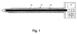
図1には、本発明によるトロカール構造のピンないし栓子ユニットが模式的に示されている。このピンは通常の穿刺の役割を有しており、それに準じて構成、寸法決めされている。 FIG. 1 schematically shows a pin or obturator unit having a trocar structure according to the present invention. This pin has a normal puncture role and is configured and dimensioned accordingly.
スリーブ15の中にあるシャフト12を通ってライトガイド14が延びており、これを起点として可視光または非可視光が、相応の波長に対して透過性に製作されたシャフト12の先端部(または相応に透明な前側端部)を通じて、検査領域へと放射される。可視光のための相応の光源7がトロカール構造の近位端にあり、ライトガイド14へと光を誘導する。非可視波長の領域の光のための光源9が、同じく図示されている。シャフト12の遠位端では、そこを起点として、画像情報が図示しない伝送装置を介してトロカール構造の近位端へ伝送される。そこには可視光と非可視光(たとえば赤外光)のためのデコーダユニット8,10がそれぞれあり、これらが光源7(たとえば冷光源)から発せられる光の波長に応じて適用される。適用される波長は、検査領域の種類や位置に準じて決まる。これが実質的に変わらないときには、必要のないデコーダユニットを省略することができる。画像コンバータが相応の光学系とともに利用されるのが好ましい。
A
光に代えて超音波を画像表示のために利用することもでき、その場合、超音波送信機と超音波受信機、ならびに伝送装置が相応に設計されて配置される。 In place of light, ultrasonic waves can also be used for image display, in which case an ultrasonic transmitter, an ultrasonic receiver, and a transmission device are appropriately designed and arranged.
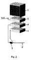
表示ユニットに、すなわち図2に示すビデオタワーのモニタ6に、画像情報信号を送信するアンテナを備えた送信ユニット16が、デコーダユニット8,10と結合されている。別案としてケーブル接続を利用することもできるが、ケーブルレス式の伝送のほうが好ましい。画像情報信号は、図示しない記憶装置へ並行して入力することもできる。
A
トロカール構造の近位端には、エネルギー供給ユニット11もある。これはたとえば光源7、光検出器8、および送信ユニット16に供給を行う。
There is also an energy supply unit 11 at the proximal end of the trocar structure. This supplies, for example, to the light source 7, the photodetector 8 and the
さらに、トロカール構造の近位端にはオン/オフスイッチ13が配置されており、これにより、トロカール構造ないしトロカール構造の各コンポーネントを、操作者により直接オン・オフすることができる。これと結合されているのがモニタ6での画像情報信号の優先的な表示であり、それに対して、たとえば気管支鏡のような内視鏡2からの標準的に結像される情報は抑圧される。輪状気管切開術の場合、内視鏡からトロカールへの単純な切換により、このような機器ないし器具の取換のときの切換ハンドグリップや切換方策を省略することで、緊急時に切迫して必要となる時間を節約することができる。
Further, an on / off switch 13 is arranged at the proximal end of the trocar structure, so that the trocar structure or each component of the trocar structure can be directly turned on and off by the operator. Combined with this is the preferential display of the image information signal on the
図2に示す、上ですでに言及したビデオタワーは、アンテナ5−5を備える受信機5を含んでおり、これを起点としてピンの画像情報信号が、モニタ6がオンになっている限りにおいてモニタ6に送られる。
The video tower already mentioned above, shown in FIG. 2, includes a
トロカール構造がオンになっていないとき、これから信号がビデオタワーに伝送されることはなく、そのときビデオタワーは通常の動作モードにあり、内視鏡2から送られて光源1、ビデオカメラ3、およびビデオリンクを通じて生成される画像情報信号を表示する。このビデオ信号はデコーダ4を介して受信機5に送られ、そこを起点としてモニタ6に表示される。
When the trocar structure is not turned on, no signal is transmitted to the video tower from now on, the video tower is in normal operating mode and is sent from the
Claims (14)
前記ピンまたはその近位端に前記画像生成手段および前記伝送装置もしくはそれらの一部が設けられており、
前記トロカール構造は最小侵襲式のワークステーションにおける使用のために設計されており、
前記ピンはオン/オフスイッチを備えており、前記最小侵襲式のワークステーションの前記表示装置は、前記オン/オフスイッチがオンになった状態では前記ピンから伝送される前記画像情報のみを表示し、前記オン/オフスイッチがオフになった状態では前記ピンから伝送される前記画像情報を表示しないで最小侵襲器具から伝送される画像情報を表示し、
前記ピンの前記オン/オフスイッチは、前記トロカールスリーブへ前記ピンを挿入することでオンになる接触スイッチである、トロカール構造。 In a trocar structure comprising a trocar sleeve provided for receiving a pin containing image generating means, the distal end of the pin is transmissive for image generation, and the image generating means is the distal of the pin. Provided for visualizing the working section through the edge, and provided with a transmission device for transmitting a signal including image information transmitted from the pin to a display device;
The image generating means and the transmission device or a part thereof are provided at the pin or the proximal end thereof,
The trocar structure is designed for use in a minimally invasive workstation,
The pin includes an on / off switch, and the display device of the minimally invasive workstation displays only the image information transmitted from the pin when the on / off switch is on. In the state where the on / off switch is turned off, the image information transmitted from the minimally invasive instrument is displayed without displaying the image information transmitted from the pin,
The trocar structure, wherein the on / off switch of the pin is a contact switch that is turned on by inserting the pin into the trocar sleeve.
前記光源は、前記ピンの外部に設けられており、
前記ピンには、前記光学式の伝送ユニットが、前記遠位端まで前記光源からの光を伝送するために、および/または前記遠位端から光検出ユニットまで光を伝送するために、配置されている、請求項1から請求項4のいずれか1項に記載のトロカール構造。 The image generating means includes a light source and an optical transmission unit for light from the light source,
The light source is provided outside the pin,
On the pin, the optical transmission unit is arranged to transmit light from the light source to the distal end and / or to transmit light from the distal end to the light detection unit. The trocar structure according to any one of claims 1 to 4, wherein the trocar structure is provided.
Applications Claiming Priority (3)
| Application Number | Priority Date | Filing Date | Title |
|---|---|---|---|
| DE102010060877A DE102010060877B4 (en) | 2010-11-29 | 2010-11-29 | trocar |
| DE102010060877.7 | 2010-11-29 | ||
| PCT/EP2011/071222 WO2012072602A1 (en) | 2010-11-29 | 2011-11-29 | Trocar system |
Publications (2)
| Publication Number | Publication Date |
|---|---|
| JP2014504179A JP2014504179A (en) | 2014-02-20 |
| JP6031040B2 true JP6031040B2 (en) | 2016-11-24 |
Family
ID=45406674
Family Applications (1)
| Application Number | Title | Priority Date | Filing Date |
|---|---|---|---|
| JP2013540413A Active JP6031040B2 (en) | 2010-11-29 | 2011-11-29 | Trocar system |
Country Status (4)
| Country | Link |
|---|---|
| US (1) | US10827907B2 (en) |
| JP (1) | JP6031040B2 (en) |
| DE (1) | DE102010060877B4 (en) |
| WO (1) | WO2012072602A1 (en) |
Families Citing this family (7)
| Publication number | Priority date | Publication date | Assignee | Title |
|---|---|---|---|---|
| DE102010060877B4 (en) | 2010-11-29 | 2013-08-29 | Reiner Kunz | trocar |
| US11547446B2 (en) | 2014-01-13 | 2023-01-10 | Trice Medical, Inc. | Fully integrated, disposable tissue visualization device |
| DE102015103214A1 (en) | 2015-03-05 | 2016-09-08 | Karl Storz Gmbh & Co. Kg | trocar |
| AU2017233052A1 (en) | 2016-03-17 | 2018-09-20 | Trice Medical, Inc. | Clot evacuation and visualization devices and methods of use |
| WO2021211404A1 (en) * | 2020-04-17 | 2021-10-21 | Yaari Abraham J | Entry system with imaging for minimally invasive surgery |
| US10997833B1 (en) | 2020-08-24 | 2021-05-04 | M&R Technology, Llc | Safety sensors |
| CN113476119B (en) * | 2021-08-20 | 2022-12-30 | 施爱德(厦门)医疗器材有限公司 | Puncture device and puncture method |
Family Cites Families (35)
| Publication number | Priority date | Publication date | Assignee | Title |
|---|---|---|---|---|
| GB8424436D0 (en) | 1984-09-27 | 1984-10-31 | Pratt Int Ltd Burnerd | Surgical appliance |
| US5685820A (en) | 1990-11-06 | 1997-11-11 | Partomed Medizintechnik Gmbh | Instrument for the penetration of body tissue |
| DE4035146A1 (en) | 1990-11-06 | 1992-05-07 | Riek Siegfried | INSTRUMENT FOR PENETRATING BODY TISSUE |
| JP3140813B2 (en) | 1991-10-17 | 2001-03-05 | オリンパス光学工業株式会社 | Endoscope TV system |
| US5392067A (en) | 1991-10-17 | 1995-02-21 | Olympus Optical Co., Ltd. | TV system for endoscopes |
| US5334150A (en) | 1992-11-17 | 1994-08-02 | Kaali Steven G | Visually directed trocar for laparoscopic surgical procedures and method of using same |
| JP2665052B2 (en) | 1993-05-14 | 1997-10-22 | エスアールアイ インターナショナル | Remote center positioning device |
| JP3431983B2 (en) | 1994-04-01 | 2003-07-28 | オリンパス光学工業株式会社 | Image processing device |
| US5686820A (en) | 1995-06-15 | 1997-11-11 | International Business Machines Corporation | Voltage regulator with a minimal input voltage requirement |
| DE19547246C1 (en) | 1995-12-18 | 1997-03-20 | Riek Siegfried | Medicinal needle containing spring-loaded guard |
| US5817061A (en) | 1997-05-16 | 1998-10-06 | Ethicon Endo-Surgery, Inc. | Trocar assembly |
| JP2000116599A (en) | 1998-10-13 | 2000-04-25 | Olympus Optical Co Ltd | Endoscopic instrument |
| DE19850224A1 (en) | 1998-10-26 | 2000-05-31 | Humboldt Uni Zu Berlin Univers | Arrangement for puncturing vessels, internal organs and space-consuming processes |
| JP4276741B2 (en) | 1999-07-28 | 2009-06-10 | オリンパス株式会社 | Endoscope device |
| JP2001177824A (en) * | 1999-12-17 | 2001-06-29 | Asahi Optical Co Ltd | Signal changeover device for electronic endoscope |
| JP2001197485A (en) * | 2000-01-11 | 2001-07-19 | Asahi Optical Co Ltd | Electronic endoscope system and electronic endoscope signal switching device |
| JP2001258835A (en) | 2000-03-16 | 2001-09-25 | Olympus Optical Co Ltd | Medical equipment |
| DE10110427A1 (en) | 2001-03-06 | 2002-09-12 | Pierre Foss | Optical aid for use in medical intubations has an endoscope type illumination device and video chip that can be inserted in the intubation tube assisting in its correct positioning and thus saving patient lives |
| US6921920B2 (en) | 2001-08-31 | 2005-07-26 | Smith & Nephew, Inc. | Solid-state light source |
| JP2003265402A (en) | 2002-03-13 | 2003-09-24 | Fuji Photo Optical Co Ltd | Laparoscope device |
| DE10333956B4 (en) | 2003-07-25 | 2005-11-03 | Richard Wolf Gmbh | Sichtobturator |
| DE10345640A1 (en) * | 2003-09-30 | 2005-04-28 | Tracoe Medical Gmbh | Device for carrying out a tracheostomy |
| US8373748B2 (en) | 2005-12-14 | 2013-02-12 | Stryker Corporation | Automatic endoscope recognition and selection of image processing and display settings |
| TW200744518A (en) * | 2006-01-06 | 2007-12-16 | Olympus Medical Systems Corp | Medical system conducted percutaneous or using naturally ocurring body orifice |
| US7927272B2 (en) * | 2006-08-04 | 2011-04-19 | Avantis Medical Systems, Inc. | Surgical port with embedded imaging device |
| DE102006051736A1 (en) | 2006-10-30 | 2008-05-08 | Geuder Ag | Medical hand-held device for lighting |
| US20100016664A1 (en) | 2006-12-20 | 2010-01-21 | Tyco Healthcare Group Lp | Surgical visual obturator |
| US20080243162A1 (en) | 2007-04-02 | 2008-10-02 | Norikiyo Shibata | Trocar |
| JP5165338B2 (en) | 2007-10-26 | 2013-03-21 | オリンパスメディカルシステムズ株式会社 | Endoscope system |
| US20090192390A1 (en) | 2008-01-24 | 2009-07-30 | Lifeguard Surgical Systems | Common bile duct surgical imaging system |
| JP4934086B2 (en) | 2008-03-14 | 2012-05-16 | オリンパスメディカルシステムズ株式会社 | Medical equipment |
| WO2010050243A1 (en) | 2008-10-31 | 2010-05-06 | 合同会社ジャパン・メディカル・クリエーティブ | Surgery device |
| DE102009010263B4 (en) | 2009-02-24 | 2011-01-20 | Reiner Kunz | Method for navigating an endoscopic instrument during technical endoscopy and associated device |
| JP5191947B2 (en) | 2009-05-18 | 2013-05-08 | 富士フイルム株式会社 | Imaging device |
| DE102010060877B4 (en) | 2010-11-29 | 2013-08-29 | Reiner Kunz | trocar |
-
2010
- 2010-11-29 DE DE102010060877A patent/DE102010060877B4/en active Active
-
2011
- 2011-11-29 US US13/990,289 patent/US10827907B2/en active Active
- 2011-11-29 JP JP2013540413A patent/JP6031040B2/en active Active
- 2011-11-29 WO PCT/EP2011/071222 patent/WO2012072602A1/en active Application Filing
Also Published As
| Publication number | Publication date |
|---|---|
| DE102010060877A1 (en) | 2012-05-31 |
| US10827907B2 (en) | 2020-11-10 |
| DE102010060877B4 (en) | 2013-08-29 |
| JP2014504179A (en) | 2014-02-20 |
| WO2012072602A1 (en) | 2012-06-07 |
| US20130245374A1 (en) | 2013-09-19 |
Similar Documents
| Publication | Publication Date | Title |
|---|---|---|
| JP6031040B2 (en) | Trocar system | |
| JP4416990B2 (en) | System for operating a device in vivo | |
| CN108430356B (en) | Vision assisted access for pneumoperitoneum needle with tapered video endoscope for mini laparoscope | |
| JP4472728B2 (en) | Endoscope system | |
| US20080147018A1 (en) | Laparoscopic cannula with camera and lighting | |
| US20060074307A1 (en) | Body cavity diagnostic system | |
| EP3220797A1 (en) | A device for use in hysteroscopy | |
| US20100010307A1 (en) | Intubation tube | |
| JP2010512959A (en) | Surgical visual occlusion device | |
| JP2010253270A (en) | Visual veress needle assembly | |
| JP2009072368A (en) | Medical apparatus | |
| US9814369B2 (en) | Pivoting three-dimensional video endoscope | |
| US20190175886A1 (en) | Force measurement instrument for sinuplasty procedure | |
| CA2842216A1 (en) | Optical obturator visualization system | |
| CN113795187A (en) | Single use endoscope, cannula and obturator with integrated vision and illumination | |
| US20120289782A1 (en) | Twin camera endoscope | |
| CN116096309A (en) | Intracavity robot (ELR) system and method | |
| CN115645013B (en) | Multi-mode tracheotomy device combined with electrocardio ultrasonic endoscope | |
| KR20180074858A (en) | Disposable Separate Endoscope Including Plastic Optical Fiber | |
| US10974034B2 (en) | Force measurement instrument for sinuplasty procedure | |
| CN112450995B (en) | Situation simulation endoscope system | |
| CN110575122A (en) | Endoscope catheter, assembly and endoscopic visible paranasal sinus balloon dilatation system | |
| CN101803904A (en) | Integrated rigid ultrasonic cystoscope system | |
| WO2020154596A1 (en) | Single use devices with integrated vision capabilities | |
| CN203016917U (en) | Laparoscope |
Legal Events
| Date | Code | Title | Description |
|---|---|---|---|
| A621 | Written request for application examination |
Free format text: JAPANESE INTERMEDIATE CODE: A621 Effective date: 20140225 |
|
| A977 | Report on retrieval |
Free format text: JAPANESE INTERMEDIATE CODE: A971007 Effective date: 20141120 |
|
| A131 | Notification of reasons for refusal |
Free format text: JAPANESE INTERMEDIATE CODE: A131 Effective date: 20141209 |
|
| A601 | Written request for extension of time |
Free format text: JAPANESE INTERMEDIATE CODE: A601 Effective date: 20150306 |
|
| A521 | Request for written amendment filed |
Free format text: JAPANESE INTERMEDIATE CODE: A523 Effective date: 20150408 |
|
| A131 | Notification of reasons for refusal |
Free format text: JAPANESE INTERMEDIATE CODE: A131 Effective date: 20150929 |
|
| A601 | Written request for extension of time |
Free format text: JAPANESE INTERMEDIATE CODE: A601 Effective date: 20151225 |
|
| A601 | Written request for extension of time |
Free format text: JAPANESE INTERMEDIATE CODE: A601 Effective date: 20160128 |
|
| A601 | Written request for extension of time |
Free format text: JAPANESE INTERMEDIATE CODE: A601 Effective date: 20160226 |
|
| A521 | Request for written amendment filed |
Free format text: JAPANESE INTERMEDIATE CODE: A523 Effective date: 20160328 |
|
| TRDD | Decision of grant or rejection written | ||
| A01 | Written decision to grant a patent or to grant a registration (utility model) |
Free format text: JAPANESE INTERMEDIATE CODE: A01 Effective date: 20160823 |
|
| A601 | Written request for extension of time |
Free format text: JAPANESE INTERMEDIATE CODE: A601 Effective date: 20160921 |
|
| A61 | First payment of annual fees (during grant procedure) |
Free format text: JAPANESE INTERMEDIATE CODE: A61 Effective date: 20161021 |
|
| R150 | Certificate of patent or registration of utility model |
Ref document number: 6031040 Country of ref document: JP Free format text: JAPANESE INTERMEDIATE CODE: R150 |
|
| R250 | Receipt of annual fees |
Free format text: JAPANESE INTERMEDIATE CODE: R250 |
|
| R250 | Receipt of annual fees |
Free format text: JAPANESE INTERMEDIATE CODE: R250 |
|
| R250 | Receipt of annual fees |
Free format text: JAPANESE INTERMEDIATE CODE: R250 |
|
| R250 | Receipt of annual fees |
Free format text: JAPANESE INTERMEDIATE CODE: R250 |
|
| R250 | Receipt of annual fees |
Free format text: JAPANESE INTERMEDIATE CODE: R250 |