JP6004833B2 - Station building power supply - Google Patents
Station building power supply Download PDFInfo
- Publication number
- JP6004833B2 JP6004833B2 JP2012182283A JP2012182283A JP6004833B2 JP 6004833 B2 JP6004833 B2 JP 6004833B2 JP 2012182283 A JP2012182283 A JP 2012182283A JP 2012182283 A JP2012182283 A JP 2012182283A JP 6004833 B2 JP6004833 B2 JP 6004833B2
- Authority
- JP
- Japan
- Prior art keywords
- power
- storage unit
- charge amount
- unit
- power storage
- Prior art date
- Legal status (The legal status is an assumption and is not a legal conclusion. Google has not performed a legal analysis and makes no representation as to the accuracy of the status listed.)
- Active
Links
Images

Description
本発明は、交流系統から供給される交流電力と列車の余剰回生電力とを併用して駅構内の空調装置や照明装置、昇降機等の各電気設備(以下、「駅負荷」という)に電力を供給する駅舎電源装置に関する。 In the present invention, AC power supplied from an AC system and surplus regenerative power of a train are used in combination to supply power to each electrical equipment (hereinafter referred to as “station load”) such as an air conditioner, a lighting device, and an elevator in a station premises. It is related with the station building power supply device to supply.
近年、直流き電系統では、列車の回生ブレーキによって発生した回生電力は、き電線を介して他の列車の力行電力として利用されている。このような直流き電系統では、同一の変電区間内において、回生電力が力行電力を上回った場合には、き電電圧が上昇し、回生電力が力行電力を下回った場合には、き電電圧が低下する。従来、例えば、回生電力が力行電力を上回る場合に生じる余剰回生電力を交流電力に変換して交流系統を介して駅負荷に供給し、駅負荷の消費電力を上回る電力を二次電池に蓄電して、き電電圧低下時に二次電池を放電してき電線に直流電力を供給することにより、き電電圧の安定化を図りつつ、交流系統に逆潮流しない範囲で、余剰回生電力を有効活用する技術が開示されている(例えば、特許文献1)。 In recent years, in a DC feeder system, regenerative power generated by a train's regenerative brake is used as powering power for other trains via feeders. In such a DC feeder system, when the regenerative power exceeds the power running power within the same substation, the feed voltage rises, and when the regenerative power falls below the power running power, the feed voltage Decreases. Conventionally, for example, surplus regenerative power generated when regenerative power exceeds powering power is converted into AC power and supplied to the station load via the AC system, and the power exceeding the power consumption of the station load is stored in the secondary battery. Technology that effectively utilizes surplus regenerative power within a range that does not reversely flow to the AC system while stabilizing the feed voltage by discharging the secondary battery and supplying DC power to the power line when the feed voltage drops Is disclosed (for example, Patent Document 1).
しかしながら、上記従来技術では、余剰回生電力が発生した時点で、駅負荷に接続された交流系統に電力を回生しているため、交流系統の電力量が間欠的に変動して不安定となる、という問題があった。 However, in the above prior art, when the excess regenerative power is generated, the power is regenerated to the AC system connected to the station load, so the power amount of the AC system fluctuates intermittently and becomes unstable. There was a problem.
本発明は、上記に鑑みてなされたものであって、駅負荷に交流電力を供給する交流系統の電力量の変動を抑制しつつ、余剰回生電力を有効活用することができる駅舎電源装置を提供することを目的とする。 The present invention has been made in view of the above, and provides a station building power supply device that can effectively utilize surplus regenerative power while suppressing fluctuations in the amount of power of an AC system that supplies AC power to a station load. The purpose is to do.
上述した課題を解決し、目的を達成するため、本発明にかかる駅舎電源装置は、交流系統から供給される交流電力と列車の余剰回生電力とを併用して駅負荷に電力を供給する駅舎電源装置であって、き電電圧を検出するき電電圧検出部と、前記余剰回生電力を貯蔵する蓄電部の充電量を検出する充電量検出部と、き電線と前記蓄電部との間で双方向に直流/直流電力変換を行う第1の電力変換部と、前記蓄電部から供給される直流電力を交流電力に変換して前記駅負荷に供給する第2の電力変換部と、前記き電電圧および前記充電量に基づいて、前記第1の電力変換部および前記第2の電力変換部を制御する制御部と、を備え、前記制御部は、前記き電電圧が所定の第1の電圧閾値を上回った場合に、前記き電線から前記蓄電部に電力を供給するように前記第1の電力変換部を制御すると共に、前記充電量が所定の第1の充電量閾値を上回った場合に、前記蓄電部から前記駅負荷に電力を供給するように前記第2の電力変換部を制御することを特徴とする。 In order to solve the above-described problems and achieve the object, the station building power supply device according to the present invention is a station building power source that supplies power to a station load using both AC power supplied from an AC system and surplus regenerative power of a train. an apparatus, between a gas collector voltage detector for detecting a feeding circuit voltage, and before Symbol charge amount detection section for detecting a charge amount of the power storage unit for storing surplus regenerative power, the feeder and the power storage unit A first power converter that performs bidirectional DC / DC power conversion, a second power converter that converts DC power supplied from the power storage unit into AC power, and supplies the AC power to the station load; A control unit that controls the first power conversion unit and the second power conversion unit based on an electric voltage and the amount of charge, and the control unit has a predetermined first voltage applied to the feeding voltage. When the voltage threshold is exceeded, power is supplied from the feeder to the power storage unit And controlling the first power conversion unit so as to supply power from the power storage unit to the station load when the charge amount exceeds a predetermined first charge amount threshold value. The power converter is controlled.
本発明によれば、駅負荷に交流電力を供給する交流系統の電力量の変動を抑制しつつ、余剰回生電力を有効活用することができる、という効果を奏する。 Advantageous Effects of Invention According to the present invention, there is an effect that surplus regenerative power can be effectively used while suppressing fluctuations in the amount of power of an AC system that supplies AC power to a station load.
以下に添付図面を参照し、本発明の実施の形態にかかる駅舎電源装置について説明する。なお、以下に示す実施の形態により本発明が限定されるものではない。 A station building power supply apparatus according to an embodiment of the present invention will be described below with reference to the accompanying drawings. In addition, this invention is not limited by embodiment shown below.
実施の形態.
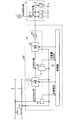
図1は、実施の形態にかかる駅舎電源装置の一構成例を示す図である。駅舎2には、交流系統1から供給された高圧の交流電力(ここでは、AC6600V系)を低圧の交流電力(ここでは、AC210V系)に変換する変圧器3が図示しない駅電気室等に設置され、駅構内の空調装置や照明装置、昇降機等の各電気設備4−1,4−2,…4−n(以下、「駅負荷4」という)に電力が供給されている。実施の形態にかかる駅舎電源装置100は、列車5が走行する変電区間内で消費しきれなかった余剰回生電力を、低圧の交流電力に変換して駅負荷4に供給するように構成される。つまり、駅負荷4には、交流系統1から供給される交流電力と変電区間内の余剰回生電力とが並行して供給される。
Embodiment.
FIG. 1 is a diagram illustrating a configuration example of a station building power supply apparatus according to the embodiment. In the
図1に示すように、実施の形態にかかる駅舎電源装置100は、き電線6とレール7との間のき電電圧(ここでは、DC1500V系)を検出するき電電圧検出部8と、列車5の走行する変電区間内の余剰回生電力を貯蔵する蓄電部9と、蓄電部9の充電量(SOC:State Of Charge)を検出する充電量検出部10と、き電線6と蓄電部9との間で双方向に直流/直流電力変換を行う双方向DC/DCコンバータ21を具備した第1の電力変換部11と、蓄電部9から供給される直流電力を交流電力に変換するインバータ22およびインバータ22の出力を駅負荷4に供給する交流電力(ここでは、AC210V系)に変換する変圧器23を具備した第2の電力変換部12と、き電電圧および蓄電部9の充電量に基づいて、第1の電力変換部11および第2の電力変換部12を制御する制御部13とを備えている。なお、充電量検出部10による充電量の検出手法については、公知の手法を用いればよく、この充電量の検出手法により本発明が限定されるものではない。また、第1の電力変換部11を構成する双方向DC/DCコンバータ21および第2の電力変換部12を構成するインバータ22の回路構成により本発明が限定されるものではない。
As shown in FIG. 1, a station building
つぎに、実施の形態にかかる駅舎電源装置100の動作概念について、図1を参照して説明する。本実施の形態では、き電電圧に対する電圧閾値(第1の電圧閾値)と、蓄電部9の充電量に対する充電量閾値(第1の充電量閾値)とを設ける。
Next, an operation concept of the station building
そして、第1の電圧閾値として、変電区間内の余剰回生電力の発生を検知する値を設定し、制御部13は、き電電圧がこの第1の電圧閾値を上回った場合に、第1の電力変換部11を制御して、き電線6から蓄電部9に電力を供給し、蓄電部9の充電を行う。
And the value which detects generation | occurrence | production of the excess regenerative electric power in a transformation area is set as a 1st voltage threshold value, and when the feeding voltage exceeds this 1st voltage threshold value, the
また、第1の充電量閾値として、蓄電部9が放電可能か否かを検知する値を設定し、制御部13は、蓄電部9の充電量がこの第1の充電量閾値を上回った場合に、第2の電力変換部12を制御して、蓄電部9から駅負荷4に電力を供給する。
Moreover, the value which detects whether the electrical storage part 9 can discharge is set as a 1st charge amount threshold value, and the
このように制御することにより、変電区間内の余剰回生電力が発生する毎に、この余剰回生電力により蓄電部9に充電し、蓄電部9が放電可能な充電量を維持している期間は、蓄電部9に充電された余剰回生電力により、連続して交流系統1から駅負荷4に供給される電力を補助することができる。これにより、き電線6の電圧変動および交流系統1から供給される電力量の変動を抑制しつつ、余剰回生電力を有効活用することができる。
By controlling in this way, whenever surplus regenerative power in the substation section is generated, the power storage unit 9 is charged with this surplus regenerative power, and the power storage unit 9 maintains a chargeable amount of discharge, Electric power continuously supplied from the AC system 1 to the
また、蓄電部9から駅負荷4に供給する電力量が略一定となるように第2の電力変換部12を制御することにより、交流系統1から供給される電力量をより安定させることができる。
Further, by controlling the second
さらに、き電電圧に対して、第1の電圧閾値よりも小さい第2の電圧閾値を設け、蓄電部9の充電量に対して、第1の充電量閾値よりも大きい第2の充電量閾値を設け、第2の電圧閾値として、変電区間内の電力が不足していることを検知する値を設定し、第2の充電量閾値として、蓄電部9が変電区間内の不足電力を補填可能か否かを検知する値を設定し、制御部13は、き電電圧が第2の電圧閾値を下回り、且つ、蓄電部9の充電量が第2の充電量閾値を上回った場合に、第1の電力変換部を制御して、蓄電部9からき電線6に電力を供給するようにしてもよい。
Furthermore, a second voltage threshold value smaller than the first voltage threshold value is provided for the feeding voltage, and a second charge amount threshold value that is greater than the first charge amount threshold value for the charge amount of the power storage unit 9. Is set as the second voltage threshold value to detect that the power in the transformation section is insufficient, and the power storage unit 9 can compensate for the insufficient power in the transformation section as the second charge amount threshold value. The
このように制御することにより、蓄電部9が変電区間内の不足電力を補填可能な充電量を維持している期間は、蓄電部9に充電された余剰回生電力により、変電区間内の不足電力を補助することができる。これにより、き電線6の電圧変動をより安定させることができる。 By controlling in this way, during the period in which the power storage unit 9 maintains a charge amount that can compensate for the insufficient power in the substation section, the insufficient power in the substation section is generated by surplus regenerative power charged in the power storage unit 9. Can assist. Thereby, the voltage fluctuation of feeder 6 can be stabilized more.
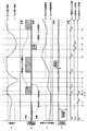
つぎに、実施の形態にかかる駅舎電源装置100の具体的な動作例について、図2を参照して説明する。図2は、実施の形態にかかる駅舎電源装置のタイムチャートの一例を示す図である。
Next, a specific operation example of the station building
図2(a)は、き電電圧の推移を示し、図2(b)は、蓄電部9の充放電電力の推移を示している。また、図2(c)は、蓄電部9の充電量の推移を示し、図2(d)は、駅負荷4の消費電力を示している。なお、図2に示す例では、蓄電部9の充電方式として定電力充電方式を用いた例を示している。また、蓄電部9からき電線6への放電についても、定電力で放電させる例を示している。これら蓄電部9の充電方式や蓄電部9からき電線6への放電方式により本発明が限定されるものではない。
2A shows the transition of the feeding voltage, and FIG. 2B shows the transition of the charge / discharge power of the power storage unit 9. FIG. 2C shows the transition of the charge amount of the power storage unit 9, and FIG. 2D shows the power consumption of the
時刻t1〜時刻t2の期間は、き電電圧が第2の電圧閾値〜第1の電圧閾値の範囲内であり(図2(a))、蓄電部9の充電量が第1の充電量閾値を上回っているので(図2(c))、制御部13は、第2の電力変換部12を動作させ、蓄電部9から駅負荷4への放電をONとしている。このとき、制御部13は、蓄電部9から駅負荷4に供給する電力量が略一定となるように、第2の電力変換部を制御している(図2(b))。
During the period from time t1 to time t2, the feeding voltage is within the range of the second voltage threshold value to the first voltage threshold value (FIG. 2A), and the charge amount of the power storage unit 9 is the first charge amount threshold value. (FIG. 2 (c)), the
蓄電部9の充電量が徐々に低下し、時刻t2において蓄電部9の充電量が第1の充電量閾値を下回ると(図2(c))、制御部13は、蓄電部9から駅負荷4に供給する電力量を徐々に減少させ、時刻t2’において蓄電部9から駅負荷4に供給する電力量が略零となると共に、第2の電力変換部12の動作を停止して、蓄電部9から駅負荷4への放電をOFFとしている。
When the charge amount of the power storage unit 9 gradually decreases and the charge amount of the power storage unit 9 falls below the first charge amount threshold value at time t2 (FIG. 2 (c)), the
また、時刻t3においてき電電圧が第1の電圧閾値を上回ると(図2(a))、制御部13は、第1の電力変換部11を動作させ、き電線6から蓄電部9への充電をONとする。その後、時刻t3’において蓄電部9の充電量が第1の充電量閾値を上回ると、制御部13は、第2の電力変換部12を動作させ、蓄電部9から駅負荷4への放電をONとし、蓄電部9から駅負荷4に供給する電力量を徐々に増加させ、時刻t3”以降、蓄電部9から駅負荷4に供給する電力量が略一定となるように、第2の電力変換部を制御する(図2(b))。
When the feeding voltage exceeds the first voltage threshold at time t3 (FIG. 2 (a)), the
時刻t3〜時刻t4の期間は、き電線6から蓄電部9への充電が行われることにより、蓄電部9の充電量が増加する(図2(c))。一方、き電電圧は、蓄電部9への充電を行わなかった場合(図2(a)中の破線で示す線)よりも低下する(図2(a)中の実線で示す線)。 During the period from time t3 to time t4, charging from the feeder 6 to the power storage unit 9 is performed, so that the amount of charge of the power storage unit 9 increases (FIG. 2 (c)). On the other hand, the feeding voltage is lower than a case where the power storage unit 9 is not charged (a line indicated by a broken line in FIG. 2A) (a line indicated by a solid line in FIG. 2A).
時刻t4においてき電電圧が第1の電圧閾値を下回ると(図2(a))、制御部13は、第1の電力変換部11の動作を停止させ、き電線6から蓄電部9への充電をOFFとする。
When the feeding voltage falls below the first voltage threshold at time t4 (FIG. 2 (a)), the
時刻t5〜時刻t6の期間は、き電電圧が第1の電圧閾値を下回っているが、蓄電部9の充電量が第2の充電量閾値を下回っているので、蓄電部9からき電線6への放電は行わない。つまり、時刻t4〜時刻t7の期間は、蓄電部9から駅負荷4への放電のみ行われることにより、蓄電部9の充電量が徐々に低下する(図2(c))。
During the period from time t5 to time t6, the feeding voltage is lower than the first voltage threshold value, but the charge amount of the power storage unit 9 is lower than the second charge amount threshold value. Is not discharged. That is, during the period from time t4 to time t7, only the discharge from the power storage unit 9 to the
時刻t7においてき電電圧が第1の電圧閾値を上回ると(図2(a))、制御部13は、第1の電力変換部11を動作させ、き電線6から蓄電部9への充電をONとする。
When the feeding voltage exceeds the first voltage threshold at time t7 (FIG. 2A), the
時刻t7〜時刻t8の期間は、時刻t3〜時刻t4の期間と同様に、き電線6から蓄電部9への充電が行われることにより、蓄電部9の充電量が増加し(図2(c))、き電電圧は、蓄電部9への充電を行わなかった場合(図2(a)中の破線で示す線)よりも低下する(図2(a)中の実線で示す線)。 In the period from time t7 to time t8, as in the period from time t3 to time t4, charging from the feeder 6 to the power storage unit 9 increases, so that the amount of charge of the power storage unit 9 increases (FIG. 2 (c) )), The feeding voltage is lower than when the power storage unit 9 is not charged (a line indicated by a broken line in FIG. 2A) (a line indicated by a solid line in FIG. 2A).
時刻t8においてき電電圧が第1の電圧閾値を下回ると(図2(a))、制御部13は、第1の電力変換部11の動作を停止させ、き電線6から蓄電部9への充電をOFFとする。
When the feeding voltage falls below the first voltage threshold at time t8 (FIG. 2 (a)), the
時刻t8〜時刻t9の期間は、き電電圧が第2の電圧閾値〜第1の電圧閾値の範囲内であり(図2(a))、蓄電部9の充電量が第1の充電量閾値を上回っているので(図2(c))、蓄電部9から駅負荷4への放電のみ行われることにより、蓄電部9の充電量が徐々に低下する(図2(c))。
During the period from time t8 to time t9, the feeding voltage is within the range of the second voltage threshold value to the first voltage threshold value (FIG. 2A), and the charge amount of the power storage unit 9 is the first charge amount threshold value. (FIG. 2 (c)), only the discharge from the power storage unit 9 to the
時刻t9においてき電電圧が第2の電圧閾値を下回ると(図2(a))、制御部13は、第1の電力変換部11を動作させ、蓄電部9からき電線6への放電をONとする。
When the feeding voltage falls below the second voltage threshold at time t9 (FIG. 2A), the
時刻t9〜時刻t10の期間は、き電電圧が第2の電圧閾値を下回り(図2(a))、且つ、時刻t5〜時刻t6の期間とは異なり、蓄電部9の充電量が第2の充電量閾値を上回っているので(図2(c))、蓄電部9から駅負荷4への放電と、蓄電部9からき電線6への放電が同時に行われることにより、蓄電部9の充電量がより低下し(図2(c))、き電電圧は、蓄電部9への放電を行わなかった場合(図2(a)中の破線で示す線)よりも上昇する(図2(a)中の実線で示す線)。
In the period from time t9 to time t10, the feeding voltage falls below the second voltage threshold (FIG. 2A), and unlike the period from time t5 to time t6, the charge amount of the power storage unit 9 is the second. The charge amount of the power storage unit 9 is increased by simultaneously discharging from the power storage unit 9 to the
時刻t10において第2の充電量閾値を下回ると(図2(c))、制御部13は、第1の電力変換部11の動作を停止させ、蓄電部9からき電線6への放電をOFFとする。
When falling below the second charge amount threshold at time t10 (FIG. 2 (c)), the
時刻t10〜時刻t11の期間は、き電電圧が第1の電圧閾値を下回っているが(図2(a))、蓄電部9の充電量が第2の充電量閾値を下回っているので(図2(c))、蓄電部9からき電線6への放電は行わない。つまり、時刻t10〜時刻t12の期間は、時刻t4〜時刻t7の期間と同様に、蓄電部9から駅負荷4への放電のみ行われることにより、蓄電部9の充電量が徐々に低下する(図2(c))。
During the period from time t10 to time t11, the feeding voltage is lower than the first voltage threshold (FIG. 2A), but the charge amount of the power storage unit 9 is lower than the second charge amount threshold ( 2 (c)), no discharge from the power storage unit 9 to the feeder 6 is performed. That is, during the period from time t10 to time t12, as in the period from time t4 to time t7, only the discharge from the power storage unit 9 to the
時刻t12においてき電電圧が第1の電圧閾値を上回ると(図2(a))、制御部13は、第1の電力変換部11を動作させ、き電線6から蓄電部9への充電ONとする。
When the feeding voltage exceeds the first voltage threshold at time t12 (FIG. 2A), the
時刻t12以降は、時刻t3〜時刻t4の期間と同様に、き電線6から蓄電部9への充電が行われることにより、蓄電部9の充電量が増加し(図2(c))、き電電圧は、蓄電部9への充電を行わなかった場合(図2(a)中の破線で示す線)よりも低下する(図2(a)中の実線で示す線)。 After time t12, as in the period from time t3 to time t4, charging from the feeder 6 to the power storage unit 9 increases, so that the charge amount of the power storage unit 9 increases (FIG. 2 (c)). The electric voltage is lower than the case where the power storage unit 9 is not charged (the line indicated by the broken line in FIG. 2A) (the line indicated by the solid line in FIG. 2A).
このように、図2に示す例では、蓄電部9の充電量が第1の充電量閾値を下回っている期間を除き、き電電圧が第1の電圧閾値を上回っている期間に蓄電部9に充電された余剰回生電力が駅負荷4に略一定の電力量で供給される。
As described above, in the example illustrated in FIG. 2, the power storage unit 9 is in a period in which the feeding voltage is higher than the first voltage threshold except for a period in which the charge amount of the power storage unit 9 is lower than the first charge amount threshold. The surplus regenerative power charged to the
ここで、余剰回生電力を貯蔵するための蓄電部を具備しない従来の構成の場合について説明する。図3は、余剰回生電力を貯蔵するための蓄電部を具備しない従来の駅舎電源装置のタイムチャートの一例を示す図である。図3(a)は、き電電圧の推移を示し、図3(b)は、駅負荷の消費電力を示している。 Here, the case of the conventional structure which does not comprise the electrical storage part for storing surplus regenerative electric power is demonstrated. FIG. 3 is a diagram illustrating an example of a time chart of a conventional station building power supply device that does not include a power storage unit for storing surplus regenerative power. FIG. 3A shows the transition of the feeding voltage, and FIG. 3B shows the power consumption of the station load.
図3に示す従来の構成では、き電電圧が電圧閾値を超えた場合、つまり、余剰回生電力が発生した場合のみ、駅負荷にき電線からの電力が供給されるため、交流系統から供給される電力量が間欠的に変動する。このため、き電線から供給される電力が駅負荷の消費電力量以下である場合でも、交流系統の総電力量が間欠的に変動することとなり、交流系統電圧の変動を招く要因となり得る。 In the conventional configuration shown in FIG. 3, since the power from the feeder is supplied to the station load only when the feeding voltage exceeds the voltage threshold, that is, when surplus regenerative power is generated, it is supplied from the AC system. The amount of power that fluctuates intermittently. For this reason, even when the power supplied from the feeder line is less than or equal to the power consumption of the station load, the total power amount of the AC system fluctuates intermittently, which may cause the AC system voltage to fluctuate.
本実施の形態の構成では、間欠的に発生する余剰回生電力を蓄電部9に貯蔵しておき、蓄電部9が放電可能な充電量を維持している期間は、蓄電部9に貯蔵された余剰回生電力により、連続して交流系統1から駅負荷4に供給される電力を補助するようにしているので、交流系統1の総電力量の変動を抑制しつつ、余剰回生電力を有効活用することができる。
In the configuration of the present embodiment, surplus regenerative power generated intermittently is stored in the power storage unit 9, and the power storage unit 9 is stored in the power storage unit 9 while maintaining a chargeable charge amount. Since the surplus regenerative power continuously assists the power supplied from the AC system 1 to the
以上説明したように、実施の形態にかかる駅舎電源装置によれば、変電区間内の余剰回生電力を貯蔵する蓄電部と、き電線と蓄電部との間で双方向に直流/直流電力変換を行う第1の電力変換部と、蓄電部から供給される直流電力を駅負荷に供給する交流電力に変換する第2の電力変換部とを備え、き電電圧に対する電圧閾値(第1の電圧閾値)と、蓄電部の充電量に対する充電量閾値(第1の充電量閾値)とを設け、第1の電圧閾値として、変電区間内の余剰回生電力の発生を検知する値を設定し、第1の充電量閾値として、蓄電部が放電可能か否かを検知する値を設定し、き電電圧が第1の電圧閾値を上回った場合に、第1の電力変換部を制御して、き電線から蓄電部に電力を供給して蓄電部の充電を行い、蓄電部の充電量が第1の充電量閾値を上回った場合に、第2の電力変換部を制御して、蓄電部から駅負荷に電力を供給するようにしたので、変電区間内の余剰回生電力が発生する毎に、この余剰回生電力により蓄電部に充電し、蓄電部が放電可能な充電量を維持している期間は、蓄電部に充電された余剰回生電力により、連続して交流系統から駅負荷に供給される電力を補助することができるので、き電線の電圧変動および交流系統から供給される電力量の変動を抑制しつつ、余剰回生電力を有効活用することができる。 As described above, according to the station building power supply apparatus according to the embodiment, the direct current / direct current power conversion is performed bidirectionally between the power storage unit that stores the surplus regenerative power in the transformer section and the feeder and the power storage unit. A first power conversion unit to perform, and a second power conversion unit that converts DC power supplied from the power storage unit to AC power supplied to the station load, and a voltage threshold for the feeding voltage (first voltage threshold) ) And a charge amount threshold value (first charge amount threshold value) with respect to the charge amount of the power storage unit, and the first voltage threshold value is set to a value for detecting occurrence of surplus regenerative power in the substation section, As a charge amount threshold value, a value for detecting whether or not the power storage unit can be discharged is set, and when the feeding voltage exceeds the first voltage threshold value, the first power conversion unit is controlled to feed Power is supplied to the power storage unit to charge the power storage unit, and the charge amount of the power storage unit is the first charge. When the threshold value is exceeded, the second power conversion unit is controlled so that power is supplied from the power storage unit to the station load. Therefore, whenever surplus regenerative power in the substation section is generated, this surplus regenerative power is generated. During the period when the power storage unit is charged by the power storage unit and the amount of charge that can be discharged by the power storage unit is maintained, the surplus regenerative power charged in the power storage unit continuously assists the power supplied from the AC system to the station load. Therefore, surplus regenerative power can be effectively utilized while suppressing fluctuations in the voltage of feeders and fluctuations in the amount of power supplied from the AC system.
また、蓄電部から駅負荷に供給する電力量が略一定となるように第2の電力変換部を制御することにより、交流系統から供給される電力量をより安定させることができる。 In addition, the amount of power supplied from the AC system can be further stabilized by controlling the second power converter so that the amount of power supplied from the power storage unit to the station load is substantially constant.
さらに、き電電圧に対して、第1の電圧閾値よりも小さい第2の電圧閾値を設け、蓄電部の充電量に対して、第1の充電量閾値よりも大きい第2の充電量閾値を設け、第2の電圧閾値として、変電区間内の電力が不足していることを検知する値を設定し、第2の充電量閾値として、蓄電部が変電区間内の不足電力を補填可能か否かを検知する値を設定し、き電電圧が第2の電圧閾値を下回り、且つ、蓄電部の充電量が第2の充電量閾値を上回った場合に、第1の電力変換部を制御して、蓄電部からき電線に電力を供給するようにすることにより、蓄電部が変電区間内の不足電力を補填可能な充電量を維持している期間は、蓄電部に充電された余剰回生電力により、変電区間内の不足電力を補助することができるので、き電線の電圧変動をより安定させることができる。 Furthermore, a second voltage threshold value smaller than the first voltage threshold value is provided for the feeding voltage, and a second charge amount threshold value larger than the first charge amount threshold value is set for the charge amount of the power storage unit. A value for detecting that the power in the substation is insufficient is set as the second voltage threshold, and whether or not the power storage unit can compensate for the insufficient power in the subsection as the second charge threshold When the feeding voltage is lower than the second voltage threshold and the charge amount of the power storage unit is higher than the second charge amount threshold, the first power conversion unit is controlled. Thus, by supplying power from the power storage unit to the feeder line, during the period in which the power storage unit maintains a charge amount that can compensate for the insufficient power in the transformation section, the excess regenerative power charged in the power storage unit , Because it can assist the power shortage in the substation section, It can be constant.
なお、以上の実施の形態に示した構成は、本発明の構成の一例であり、別の公知の技術と組み合わせることも可能であるし、本発明の要旨を逸脱しない範囲で、一部を省略する等、変更して構成することも可能であることは言うまでもない。 Note that the configuration shown in the above embodiment is an example of the configuration of the present invention, and can be combined with another known technique, and a part thereof is omitted without departing from the gist of the present invention. Needless to say, it is possible to change the configuration.
1 交流系統、2 駅舎、3 変圧器、4,4−1,4−2,…4−n 駅負荷、5 列車、6 き電線、7 レール、8 き電電圧検出部、9 蓄電部、10 充電量検出部、11 第1の電力変換部、12 第2の電力変換部、13 制御部、21 双方向DC/DCコンバータ、22 インバータ、23 変圧器、100 駅舎電源装置。 1 AC system, 2 station building, 3 transformer, 4,4-1, 4-2, ... 4-n station load, 5 trains, 6 feeders, 7 rails, 8 feeders voltage detector, 9 electricity storage, 10 Charge amount detection unit, 11 first power conversion unit, 12 second power conversion unit, 13 control unit, 21 bidirectional DC / DC converter, 22 inverter, 23 transformer, 100 station building power supply device.
Claims (5)
き電電圧を検出するき電電圧検出部と、
前記余剰回生電力を貯蔵する蓄電部の充電量を検出する充電量検出部と、
き電線と前記蓄電部との間で双方向に直流/直流電力変換を行う第1の電力変換部と、
前記蓄電部から供給される直流電力を交流電力に変換して前記駅負荷に供給する第2の電力変換部と、
前記き電電圧および前記充電量に基づいて、前記第1の電力変換部および前記第2の電力変換部を制御する制御部と、
を備え、
前記制御部は、前記き電電圧が所定の第1の電圧閾値を上回った場合に、前記き電線から前記蓄電部に電力を供給するように前記第1の電力変換部を制御し、前記充電量が所定の第1の充電量閾値を上回った場合に、前記蓄電部から前記駅負荷に電力を供給するように前記第2の電力変換部を制御し、前記き電電圧が前記第1の電圧閾値よりも小さい第2の電圧閾値を下回り、且つ、前記充電量が前記第1の充電量閾値よりも大きい第2の充電量閾値を上回った場合に、前記蓄電部から前記き電線に電力を供給するように前記第1の電力変換部を制御する
ことを特徴とする駅舎電源装置。 A station building power supply device that supplies power to a station load using both AC power supplied from an AC system and surplus regenerative power of a train,
A feeding voltage detection unit for detecting feeding voltage ;
A charge amount detection unit that detects a charge amount of a power storage unit that stores the surplus regenerative power ; and
A first power converter that performs direct current / direct current power conversion between the feeder and the power storage unit;
A second power conversion unit that converts DC power supplied from the power storage unit into AC power and supplies the station load;
A control unit for controlling the first power conversion unit and the second power conversion unit based on the feeding voltage and the charge amount;
With
The control unit controls the first power conversion unit to supply power from the feeder to the power storage unit when the feeding voltage exceeds a predetermined first voltage threshold, and the charging When the amount exceeds a predetermined first charge amount threshold, the second power conversion unit is controlled to supply power from the power storage unit to the station load, and the feeding voltage is the first charging voltage. When the charge amount falls below a second voltage threshold value that is smaller than the voltage threshold value and the charge amount exceeds a second charge amount threshold value that is greater than the first charge amount threshold value, power is supplied from the power storage unit to the feeder line. The station power supply apparatus is characterized in that the first power conversion unit is controlled so as to supply the power.
き電電圧を検出するき電電圧検出部と、
き電線と前記余剰回生電力を貯蔵する蓄電部との間で双方向に直流/直流電力変換を行う第1の電力変換部と、
前記蓄電部から供給される直流電力を交流電力に変換して前記駅負荷に供給する第2の電力変換部と、
前記蓄電部の充電量を検出する充電量検出部と、
前記き電電圧および前記充電量に基づいて、前記第1の電力変換部および前記第2の電力変換部を制御する制御部と、
を備え、
前記制御部は、前記き電電圧が所定の第1の電圧閾値を上回った場合に、前記き電線から前記蓄電部に電力を供給するように前記第1の電力変換部を制御し、前記充電量が所定の第1の充電量閾値を上回った場合に、前記蓄電部から前記駅負荷に電力を供給するように前記第2の電力変換部を制御し、前記充電量が前記第1の充電量閾値を下回った場合に、前記蓄電部から前記駅負荷に供給する電力量を所定の時間をかけて減少させるように前記第2の電力変換部を制御する
ことを特徴とする駅舎電源装置。 A station building power supply device that supplies power to a station load using both AC power supplied from an AC system and surplus regenerative power of a train,
A feeding voltage detection unit for detecting feeding voltage ;
A first power conversion unit that performs DC / DC power conversion bidirectionally between a feeder and a power storage unit that stores the surplus regenerative power ;
A second power conversion unit that converts DC power supplied from the power storage unit into AC power and supplies the station load;
A charge amount detection section for detecting the charge amount before Symbol power storage unit,
A control unit for controlling the first power conversion unit and the second power conversion unit based on the feeding voltage and the charge amount;
With
Wherein, when the feeding circuit voltage exceeds a predetermined first voltage threshold, and controls the first power conversion unit to supply power to the power storage unit from said-out wire, the charge When the amount exceeds a predetermined first charge amount threshold, the second power conversion unit is controlled to supply power from the power storage unit to the station load, and the charge amount is the first charge. The station power supply unit , wherein the second power conversion unit is controlled so that the amount of power supplied from the power storage unit to the station load is decreased over a predetermined time when the amount is below a threshold value .
き電電圧を検出するき電電圧検出部と、 A feeding voltage detection unit for detecting feeding voltage;
前記余剰回生電力を貯蔵する蓄電部の充電量を検出する充電量検出部と、 A charge amount detection unit that detects a charge amount of a power storage unit that stores the surplus regenerative power; and
き電線と前記蓄電部との間で双方向に直流/直流電力変換を行う第1の電力変換部と、 A first power converter that performs direct current / direct current power conversion between the feeder and the power storage unit;
前記蓄電部から供給される直流電力を交流電力に変換して前記駅負荷に供給する第2の電力変換部と、 A second power conversion unit that converts DC power supplied from the power storage unit into AC power and supplies the station load;
前記き電電圧および前記充電量に基づいて、前記第1の電力変換部および前記第2の電力変換部を制御する制御部と、 A control unit for controlling the first power conversion unit and the second power conversion unit based on the feeding voltage and the charge amount;
を備え、 With
前記制御部は、前記充電量が所定の第1の充電量閾値を上回った場合に、前記蓄電部から前記駅負荷に電力を供給するように前記第2の電力変換部を制御し、前記充電量が前記第1の充電量閾値よりも大きい第2の充電量閾値を上回った場合に、前記蓄電部から前記き電線に電力を供給するように前記第1の電力変換部を制御する The control unit controls the second power conversion unit to supply power from the power storage unit to the station load when the charge amount exceeds a predetermined first charge amount threshold, and the charge When the amount exceeds a second charge amount threshold value that is larger than the first charge amount threshold value, the first power conversion unit is controlled to supply power from the power storage unit to the feeder line.
ことを特徴とする駅舎電源装置。 A station building power supply device characterized by that.
き電電圧を検出するき電電圧検出部と、 A feeding voltage detection unit for detecting feeding voltage;
前記余剰回生電力を貯蔵する蓄電部の充電量を検出する充電量検出部と、 A charge amount detection unit that detects a charge amount of a power storage unit that stores the surplus regenerative power; and
き電線と前記蓄電部との間で双方向に直流/直流電力変換を行う第1の電力変換部と、 A first power converter that performs direct current / direct current power conversion between the feeder and the power storage unit;
前記蓄電部から供給される直流電力を交流電力に変換して前記駅負荷に供給する第2の電力変換部と、 A second power conversion unit that converts DC power supplied from the power storage unit into AC power and supplies the station load;
前記き電電圧および前記充電量に基づいて、前記第1の電力変換部および前記第2の電力変換部を制御する制御部と、 A control unit for controlling the first power conversion unit and the second power conversion unit based on the feeding voltage and the charge amount;
を備え、 With
前記制御部は、前記充電量が所定の第1の充電量閾値を上回った場合に、前記蓄電部から前記駅負荷に電力を供給する電力が一定となるように前記第2の電力変換部を制御する When the charge amount exceeds a predetermined first charge amount threshold, the control unit controls the second power conversion unit so that the power supplied from the power storage unit to the station load is constant. Control
ことを特徴とする駅舎電源装置。 A station building power supply device characterized by that.
Priority Applications (1)
| Application Number | Priority Date | Filing Date | Title |
|---|---|---|---|
| JP2012182283A JP6004833B2 (en) | 2012-08-21 | 2012-08-21 | Station building power supply |
Applications Claiming Priority (1)
| Application Number | Priority Date | Filing Date | Title |
|---|---|---|---|
| JP2012182283A JP6004833B2 (en) | 2012-08-21 | 2012-08-21 | Station building power supply |
Publications (3)
| Publication Number | Publication Date |
|---|---|
| JP2014040127A JP2014040127A (en) | 2014-03-06 |
| JP2014040127A5 JP2014040127A5 (en) | 2015-03-26 |
| JP6004833B2 true JP6004833B2 (en) | 2016-10-12 |
Family
ID=50392796
Family Applications (1)
| Application Number | Title | Priority Date | Filing Date |
|---|---|---|---|
| JP2012182283A Active JP6004833B2 (en) | 2012-08-21 | 2012-08-21 | Station building power supply |
Country Status (1)
| Country | Link |
|---|---|
| JP (1) | JP6004833B2 (en) |
Families Citing this family (9)
| Publication number | Priority date | Publication date | Assignee | Title |
|---|---|---|---|---|
| KR101636898B1 (en) * | 2014-04-02 | 2016-07-07 | 한국철도기술연구원 | Train station power management apparatus |
| WO2016132508A1 (en) * | 2015-02-19 | 2016-08-25 | 三菱電機株式会社 | Station power supply, and method for calculating regeneration determination voltage value |
| JP6001795B1 (en) * | 2015-03-05 | 2016-10-05 | 三菱電機株式会社 | Station building power supply |
| JP2017158356A (en) * | 2016-03-03 | 2017-09-07 | 株式会社東芝 | Power supply system |
| DE112016007040T5 (en) | 2016-07-04 | 2019-04-04 | Mitsubishi Electric Corporation | RAILWAY BUILDING POWER SUPPLY AND LOAD STATUS DETECTION METHOD |
| JP6818646B2 (en) * | 2017-07-07 | 2021-01-20 | 三菱電機株式会社 | Charge / discharge control device, storage control system, and charge / discharge control method |
| JP6993803B2 (en) * | 2017-07-26 | 2022-01-14 | 株式会社東芝 | Regenerative control system for electric railways |
| CN108773299B (en) * | 2018-06-06 | 2021-06-29 | 安徽施耐德成套电气有限公司 | Power management system for electrified rail transit |
| KR102113270B1 (en) * | 2018-11-14 | 2020-06-02 | 한국철도기술연구원 | Energy Management System for Railway station and Hydrogen Fuel Cell Hybrid Railway Vehicle |
Family Cites Families (7)
| Publication number | Priority date | Publication date | Assignee | Title |
|---|---|---|---|---|
| JP3964857B2 (en) * | 2003-12-04 | 2007-08-22 | 株式会社日立製作所 | Regenerative power absorption control method for electric railways |
| JP4432675B2 (en) * | 2004-08-25 | 2010-03-17 | 株式会社日立製作所 | Power converter |
| US8598739B2 (en) * | 2008-02-29 | 2013-12-03 | Kawasaki Jukogyo Kabushiki Kaisha | Electric railway power-supply system |
| JP2010000810A (en) * | 2008-06-18 | 2010-01-07 | Meidensha Corp | Feeder system of dc feeding network |
| JP5187624B2 (en) * | 2008-06-30 | 2013-04-24 | 川崎重工業株式会社 | Microgrid using electric railway system |
| JP2010098866A (en) * | 2008-10-17 | 2010-04-30 | Panasonic Corp | Imbalance determination circuit, imbalance reduction circuit, battery power supply, and imbalance evaluation method |
| JP2011126370A (en) * | 2009-12-16 | 2011-06-30 | Kawasaki Heavy Ind Ltd | Power supply system and power supply method |
-
2012
- 2012-08-21 JP JP2012182283A patent/JP6004833B2/en active Active
Also Published As
| Publication number | Publication date |
|---|---|
| JP2014040127A (en) | 2014-03-06 |
Similar Documents
| Publication | Publication Date | Title |
|---|---|---|
| JP6004833B2 (en) | Station building power supply | |
| JP6459085B2 (en) | Charging facility and energy management method | |
| JP5735061B2 (en) | Train power supply system | |
| CN103874649B (en) | The regeneration storage battery control setup of elevator | |
| JP5044340B2 (en) | Substation and electric railway feeding system using power storage elements | |
| WO2015079544A1 (en) | Station building power supply device | |
| JP5752562B2 (en) | Control system for power storage device for DC electric railway | |
| JP2013023074A (en) | Railway feeding system | |
| JP2014040127A5 (en) | ||
| JP4432675B2 (en) | Power converter | |
| JP2008154355A (en) | Accumulation equipment | |
| JP2006034041A (en) | Controller for feeder system power storage system | |
| JP5398433B2 (en) | Electric railway power system | |
| US10372101B2 (en) | Station auxiliary power source apparatus | |
| JP6207917B2 (en) | Control device | |
| JP5509442B2 (en) | Power converter and electric railway system | |
| JP6132753B2 (en) | Station building power supply | |
| JP5906153B2 (en) | Charger | |
| JP2016094054A (en) | Power conversion equipment | |
| JP2023168882A (en) | Power storage device, and power storage control method | |
| JP2009023369A (en) | Feeder voltage compensating device for dc railroad |
Legal Events
| Date | Code | Title | Description |
|---|---|---|---|
| A521 | Request for written amendment filed |
Free format text: JAPANESE INTERMEDIATE CODE: A523 Effective date: 20150209 |
|
| A621 | Written request for application examination |
Free format text: JAPANESE INTERMEDIATE CODE: A621 Effective date: 20150209 |
|
| A131 | Notification of reasons for refusal |
Free format text: JAPANESE INTERMEDIATE CODE: A131 Effective date: 20160119 |
|
| A521 | Request for written amendment filed |
Free format text: JAPANESE INTERMEDIATE CODE: A523 Effective date: 20160317 |
|
| TRDD | Decision of grant or rejection written | ||
| A01 | Written decision to grant a patent or to grant a registration (utility model) |
Free format text: JAPANESE INTERMEDIATE CODE: A01 Effective date: 20160809 |
|
| A61 | First payment of annual fees (during grant procedure) |
Free format text: JAPANESE INTERMEDIATE CODE: A61 Effective date: 20160906 |
|
| R150 | Certificate of patent or registration of utility model |
Ref document number: 6004833 Country of ref document: JP Free format text: JAPANESE INTERMEDIATE CODE: R150 |
|
| R250 | Receipt of annual fees |
Free format text: JAPANESE INTERMEDIATE CODE: R250 |
|
| R250 | Receipt of annual fees |
Free format text: JAPANESE INTERMEDIATE CODE: R250 |
|
| R250 | Receipt of annual fees |
Free format text: JAPANESE INTERMEDIATE CODE: R250 |
|
| R250 | Receipt of annual fees |
Free format text: JAPANESE INTERMEDIATE CODE: R250 |
|
| R250 | Receipt of annual fees |
Free format text: JAPANESE INTERMEDIATE CODE: R250 |