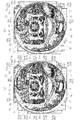
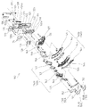
(パチンコ機)
実施例に係るパチンコ機10は、図1に示すように、前後に開口する矩形枠状に形成されて遊技店の図示しない設置枠台に縦置き姿勢で設置される固定枠としての外枠11の開口前面側に、遊技盤20を着脱可能に保持する本体枠としての中枠12が開閉および着脱可能に組み付けられて、該遊技盤20の裏側に、所定条件の成立(始動入賞口へのパチンコ球の入賞)を契機として図柄を変動表示させて図柄変動演出を行う図柄表示装置17(図2参照)が着脱可能に配設されている。また、中枠12の前面側には、遊技盤20を透視保護するガラス板や透明な合成樹脂材により形成された透視保護板(図示せず)で前後に開口する窓口13aを覆うよう構成された装飾枠としての前枠13が開閉可能に組み付けられると共に、該前枠13の下方にパチンコ球を貯留する下球受け皿15が開閉可能に組み付けられる。なお、実施例では、前枠13の下部位置に、パチンコ球を貯留する上球受け皿14が一体的に組み付けられており、前枠13の開閉に合わせて上球受け皿14も一体的に開閉するよう構成される。
(Pachinko machine)
As shown in FIG. 1, the pachinko machine 10 according to the embodiment is formed in a rectangular frame shape that opens front and rear, and an outer frame 11 as a fixed frame that is installed in a vertically installed posture on an installation frame base (not shown) of a game shop. An inner frame 12 as a main body frame that detachably holds the game board 20 is detachably assembled to the front side of the opening, and a predetermined condition is established on the back side of the game board 20 (to the start prize opening). A symbol display device 17 (see FIG. 2) is provided in a detachable manner for performing a symbol variation effect by variably displaying symbols when a pachinko ball is won. In addition, the front side of the middle frame 12 is configured to cover the window 13a opening front and rear with a glass plate that protects the game board 20 from see-through and a see-through protection plate (not shown) formed of a transparent synthetic resin material. A front frame 13 as a decorative frame is assembled so as to be openable and closable, and a lower ball tray 15 for storing pachinko balls is assembled below the front frame 13 so as to be openable and closable. In the embodiment, an upper ball tray 14 for storing pachinko balls is integrally assembled at a lower position of the front frame 13, and the upper ball tray 14 is also opened and closed integrally with the opening and closing of the front frame 13. It is configured as follows.
前記中枠12の右下方位置には、該中枠12に配設された打球発射装置(図示せず)を作動する操作ハンドル16が設けられている。操作ハンドル16は、左回転方向に付勢されており、該操作ハンドル16を右回転するよう遊技者が回動操作することで打球発射装置が作動されて、上球受け皿14に貯留されたパチンコ球が遊技盤20の遊技領域20aに向けて1球ずつ発射されるようになっている。ここで、操作ハンドル16の回動量に応じて打球発射装置によるパチンコ球の打球力が強弱変化するよう構成されており、遊技者が操作ハンドル16の回動量を調節することで、遊技領域20aへのパチンコ球の発射位置を任意に変更し得るようになっている。なお、実施例では、図柄表示装置17としては、飾図の他に各種絵柄やキャラクタ等を表示可能な液晶パネルを収容ケースに収容した液晶表示装置が採用されているが、これに限られるものではなく、ドラム式の図柄表示装置やドットマトリックス式の図柄表示装置等の各種図柄を停止および変動表示可能な従来公知の各種の表示装置を採用し得る。また、上球受け皿14は、前枠13と別体に形成して中枠12に対して開閉可能に組み付けるようにしてもよい。
An operation handle 16 for operating a ball striking device (not shown) disposed on the middle frame 12 is provided at a lower right position of the middle frame 12. The operation handle 16 is biased in the counterclockwise direction. When the player rotates the operation handle 16 to rotate it to the right, the hitting ball launching device is activated and the pachinko stored in the upper ball tray 14 is operated. The balls are fired one by one toward the game area 20a of the game board 20. Here, the hitting force of the pachinko ball by the hitting ball launcher is changed in accordance with the turning amount of the operation handle 16, and the player adjusts the turning amount of the operation handle 16 to the game area 20a. The pachinko ball launch position can be changed arbitrarily. In the embodiment, as the symbol display device 17, a liquid crystal display device in which a liquid crystal panel capable of displaying various designs, characters, and the like in addition to the decorative drawing is accommodated in the accommodation case is used. Instead, various conventionally known display devices capable of stopping and variably displaying various symbols such as a drum-type symbol display device and a dot matrix-type symbol display device can be adopted. Further, the upper ball tray 14 may be formed separately from the front frame 13 and assembled to the middle frame 12 so as to be opened and closed.
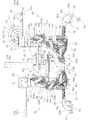
(遊技盤)
図2〜図5に示すように、前記遊技盤20は、ベニヤ材や合成樹脂材により形成された略矩形状の板部材であって、遊技盤20の裏面側に、図柄表示装置17が取り付けられた設置部材22(図6参照)が着脱可能に組み付けられている。遊技盤20の前面には、略円形状に湾曲形成した案内レール24が配設されており、該案内レール24により画成される略円形の遊技領域20aに、中枠12に配設された図示しない打球発射装置から発射されたパチンコ球が打ち出されることで遊技が行われるようになっている。また、遊技盤20には、前後に貫通する装着口20bが適宜位置に開設されており、各装着口20bに対して各種の遊技盤設置部品(具体的には枠状装飾体26、始動入賞装置30,35、特別入賞装置32、普通入賞装置36等)が前側から取り付けられると共に、遊技領域20aの最下部位置には、該遊技領域20aに打ち出されたパチンコ球を排出するアウト口25が開設されている。なお、装着口25bの形成数は、遊技盤20に取り付けられる各種遊技盤設置部品の個数や配設位置等により必要に応じて適宜変更される。
(Game board)
As shown in FIGS. 2 to 5, the game board 20 is a substantially rectangular plate member formed of a veneer material or a synthetic resin material, and a symbol display device 17 is attached to the back side of the game board 20. The installed installation member 22 (see FIG. 6) is assembled in a detachable manner. A guide rail 24 that is curved in a substantially circular shape is disposed on the front surface of the game board 20. The guide rail 24 is disposed on the middle frame 12 in a substantially circular game area 20 a defined by the guide rail 24. A game is played when a pachinko ball launched from a not-shown hitting device is launched. In addition, the game board 20 has an opening 20b penetrating in the front-rear direction at an appropriate position, and various game board installation parts (specifically, a frame-shaped decorative body 26, a start prize) for each installation opening 20b. (Devices 30, 35, special prize-winning device 32, normal prize-winning device 36, etc.) are attached from the front side, and at the lowest position of the game area 20a, an out port 25 for discharging pachinko balls launched into the game area 20a. It has been established. It should be noted that the number of the mounting openings 25b is appropriately changed as necessary depending on the number of various game board installation parts attached to the game board 20 and the arrangement positions.
前記遊技盤20には、図2〜図4に示すように、案内レール24で囲まれた遊技領域20aの略中央で開口する装着口25bに、前後に開口する表示窓口26aが形成されたセンター役とも称される枠状装飾体26が取り付けられ、該枠状装飾体26の表示窓口26aを介して図柄表示装置17の画像表示部(表示部)17aが遊技盤20の前面側に臨むよう構成されている。なお、遊技盤20には、遊技領域20a内に多数の遊技釘が設けられており、遊技領域20aを流下するパチンコ球が遊技釘に接触することで、流下方向が不規則に変化するよう構成されている。
As shown in FIGS. 2 to 4, the game board 20 has a display window 26 a that opens in the front and rear at a mounting opening 25 b that opens at the approximate center of the game area 20 a surrounded by the guide rail 24. A frame-shaped decorative body 26, also called a role, is attached so that the image display unit (display unit) 17 a of the symbol display device 17 faces the front side of the game board 20 through the display window 26 a of the frame-shaped decorative body 26. It is configured. The game board 20 is provided with a large number of game nails in the game area 20a, and the flow direction changes irregularly when a pachinko ball flowing down the game area 20a contacts the game nail. Has been.
(枠状装飾体)
前記枠状装飾体26は、下縁部を除く全周に亘って遊技盤20の前面から前方へ突出するよう形成されて、遊技領域20aと表示窓口26aとを区画するよう構成されており、遊技領域20aを流下するパチンコ球が枠状装飾体26の表示窓口26aの内側に進入しないようになっている。すなわち、実施例の遊技領域20aは、枠状装飾体26の左側に画成される第1球流下経路と、当該枠状装飾体26の右側に画成される第2球流下経路とに区画されて、遊技盤20の遊技領域20aに打ち出されるパチンコ球の位置や発射強度に応じて、該第1球流下経路または第2球流下経路をパチンコ球が流下するようになっている。枠状装飾体26の下部(開口下縁部)には、図2に示すように、パチンコ球が左右に転動可能なステージ27が設けられている。また、枠状装飾体26におけるステージ27の後端部には、表示窓口26aの内側へ延出する透明な規制壁が設けられており、該ステージ28上を転動するパチンコ球が後方(遊技盤20の裏側)へ移動するのを防止している。
(Frame decoration)
The frame-shaped decorative body 26 is formed so as to protrude forward from the front surface of the game board 20 over the entire circumference except the lower edge portion, and is configured to partition the game area 20a and the display window 26a. Pachinko balls that flow down the game area 20 a do not enter the inside of the display window 26 a of the frame-shaped decorative body 26. In other words, the game area 20a of the embodiment is divided into a first ball flow path defined on the left side of the frame-shaped decorative body 26 and a second ball flow path defined on the right side of the frame-shaped decorative body 26. Thus, the pachinko balls flow down the first ball flow path or the second ball flow path in accordance with the position and launch strength of the pachinko balls launched into the game area 20a of the game board 20. As shown in FIG. 2, a stage 27 on which a pachinko ball can roll to the left and right is provided at the lower portion (lower edge of the opening) of the frame-shaped decorative body 26. In addition, a transparent regulating wall extending inward of the display window 26a is provided at the rear end portion of the stage 27 in the frame-shaped decorative body 26, and a pachinko ball that rolls on the stage 28 is located behind (game). The movement to the back side of the panel 20 is prevented.
図2〜図4に示すように、遊技盤20には、枠状装飾体26の下方位置に第1始動入賞装置30が配設され、遊技領域20aの左右方向中央部に開口する第1始動入賞口30aに遊技領域20aを流下するパチンコ球が入賞することで、図柄表示装置17での図柄変動を開始したり、所定数の賞球の払い出しなどが行われる。また、遊技盤20には、始動入賞装置30の右上位置に特別入賞装置32が配設され、該特別入賞装置32には遊技領域20aに臨むように特別入賞口32aが設けられている。特別入賞装置32は、大当り時などの所定の遊技状態において、特別入賞口32aを塞ぐ開閉扉33を開放変位して、特別入賞口32aを開放するようになっている。そして、遊技領域20aを流下するパチンコ球が特別入賞口32aに入賞することで、所定数の賞球の払い出しなどが行われる。また、遊技盤20には、特別入賞口32aの上側位置に、パチンコ球が通過可能なゲート34が配設され、遊技領域20aを流下するパチンコ球がゲート34を通過することを契機として、第1始動入賞装置30の右側位置に配置された第2始動入賞装置35の始動入賞口(図示せず)に配設された開閉部材(図示せず)を開放するなどが行われる。更に、遊技盤20には、遊技領域20aの左側下部に普通入賞装置36が配設され、遊技領域20aに開口する普通入賞口に該遊技領域20を流下するパチンコ球が入賞することで、所定数の賞球の払い出しなどが行われるようになっている。
As shown in FIGS. 2 to 4, the game board 20 is provided with a first start winning device 30 at a position below the frame-shaped decorative body 26, and opens at the center in the left-right direction of the game area 20 a. When the pachinko ball flowing down the game area 20a wins the winning opening 30a, the symbol change in the symbol display device 17 is started, or a predetermined number of award balls are paid out. Further, the game board 20 is provided with a special prize device 32 at the upper right position of the start prize device 30, and the special prize device 32 is provided with a special prize port 32a so as to face the game area 20a. The special prize-winning device 32 opens and displaces the opening / closing door 33 that closes the special prize-winning opening 32a in a predetermined game state such as a big hit, thereby opening the special prize-winning opening 32a. Then, when a pachinko ball flowing down the game area 20a wins a special prize opening 32a, a predetermined number of prize balls are paid out. In addition, the game board 20 is provided with a gate 34 through which the pachinko ball can pass at the upper position of the special prize opening 32a, and the pachinko ball flowing down the game area 20a passes through the gate 34. For example, an opening / closing member (not shown) disposed at a start winning opening (not shown) of the second start winning device 35 arranged at the right position of the first start winning device 30 is opened. Further, the game board 20 is provided with a normal winning device 36 at the lower left portion of the game area 20a, and a pachinko ball flowing down the game area 20 wins a predetermined prize by opening a normal winning opening opened in the game area 20a. A number of prize balls are paid out.
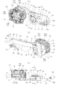
(設置部材)
図6に示すように、前記設置部材22は、略矩形状の背面板23aと、該背面板23aの外周縁部から前方に突出する画壁部23bとから前方に開口した箱状に形成されて、該画壁部23bの開口前端部を遊技盤20の裏面に当接させた状態で、当該遊技盤20と設置部材22とがネジにより固定される。そして、設置部材22において遊技盤20との間に画成される空間に、可動演出装置40および動作演出装置100などの各種装置が設置されて、設置部材22を基材とする1つのユニットとして扱い得るようになっている。また、設置部材22の背面板23aには、枠状装飾体26の表示窓口26aと前後に整列する位置に、略矩形状の設置開口部22aが前後に開口するよう開設されると共に、該背面板23aの裏側に図柄表示装置17が着脱自在に取付けられて、該設置開口部22aを介して図柄表示装置17の画像表示部17aが遊技盤20の前側に臨むようになっている。
(Installation material)
As shown in FIG. 6, the installation member 22 is formed in a box shape opened forward from a substantially rectangular back plate 23a and an image wall portion 23b protruding forward from the outer peripheral edge of the back plate 23a. Thus, the game board 20 and the installation member 22 are fixed with screws in a state in which the opening front end portion of the wall portion 23b is in contact with the back surface of the game board 20. Then, various devices such as the movable effect device 40 and the motion effect device 100 are installed in a space defined between the game board 20 and the installation member 22 as a single unit using the installation member 22 as a base material. It can be handled. In addition, a substantially rectangular installation opening 22a is opened on the back plate 23a of the installation member 22 in a position aligned with the display window 26a of the frame-shaped decorative body 26 in the front-rear direction. The symbol display device 17 is detachably attached to the back side of the face plate 23a, and the image display unit 17a of the symbol display device 17 faces the front side of the game board 20 through the installation opening 22a.
(演出手段)
図6に示すように、設置部材22の前側には、可動演出体42により動作演出を行う可動演出装置40と、動作演出体102,102により動作演出を行う動作演出装置100とからなる演出手段が設置されている。設置部材22における設置開口部22aの上側には、可動演出装置40が背面板23aの前面に取り付けられ、設置部材22における設置開口部22aの横側には、動作演出装置100が背面板23aの前面に取り付けられている。実施例では、設置部材22における設置開口部22aの左右両側に、動作演出装置100の動作演出体102およびこの動作演出体102を動作するための動作機構を備えた動作ユニットUが夫々配設されている。図5(a)に示すように、可動演出装置40は、遊技盤20と設置部材22とを組み付けた際に、設置部材22の背面板23a上部と、この背面板23a上部の前側に配置される枠状装飾体26の上部を構成する上枠装飾部37との間に画成される上部設置スペースSHに配設されている。また、動作演出装置100における左側の動作ユニットULは、遊技盤20と設置部材22とを組み付けた際に、設置部材22の背面板23a左側部と、この背面板23a左側部の前側に配置される枠状装飾体26の左側部を構成する左枠装飾部38および遊技盤左側部との間に画成される左側部設置スペースSLに配設されている。図5(b)に示すように、動作演出装置100における右側の動作ユニットURは、設置部材22の背面板23a右側部と、この背面板23a右側部の前側に配置される側部演出装置39との間に画成される右側部設置スペースSRに配設されている。
(Direction means)
As shown in FIG. 6, on the front side of the installation member 22, rendering means comprising a movable rendering device 40 that performs a motion rendering with a movable rendering body 42 and a motion rendering device 100 that performs a motion rendering with the motion rendering bodies 102 and 102. Is installed. On the upper side of the installation opening 22a in the installation member 22, the movable effect device 40 is attached to the front surface of the back plate 23a, and on the side of the installation opening 22a in the installation member 22, the operation effect device 100 is on the back plate 23a. Attached to the front. In the embodiment, on both the left and right sides of the installation opening 22 a in the installation member 22, an operation effect body 102 of the operation effect device 100 and an operation unit U including an operation mechanism for operating the operation effect body 102 are arranged. ing. As shown in FIG. 5 (a), when the game board 20 and the installation member 22 are assembled, the movable effect device 40 is disposed on the rear plate 23a of the installation member 22 and on the front side of the upper portion of the rear plate 23a. It is disposed in an upper installation space SH defined between the upper frame decoration portion 37 constituting the upper portion of the frame-shaped decorative body 26. Further, the left operation unit UL in the operation effect device 100 is arranged on the left side of the back plate 23a of the installation member 22 and the front side of the left side of the back plate 23a when the game board 20 and the installation member 22 are assembled. The frame-shaped decorative body 26 is disposed in a left-side installation space SL defined between the left-frame decorative portion 38 constituting the left-side portion of the frame-shaped decorative body 26 and the game board left-side portion. As shown in FIG. 5B, the right motion unit UR in the motion effect device 100 includes a right side portion of the back plate 23a of the installation member 22 and a side effect device 39 arranged on the front side of the right side portion of the back plate 23a. Are disposed in the right side installation space SR defined between the two.
前記演出手段は、少なくとも遊技盤20の前側から視認可能な部位において、可動演出体42および動作演出体102,102が動作するよう構成されて、パチンコ機10での遊技演出に応じて、可動演出体42および動作演出体102,102により所定の動作演出を行うようになっている。ここで、パチンコ機10で実行される遊技演出とは、図柄表示装置17の画像表示部17aにおいての各種図柄が変動する図柄変動演出、リーチ演出、リーチ予告演出、大当り演出等の表示による演出、スピーカからの音声出力による演出、光を照射し得る装置による光による演出などを指す。なお、パチンコ機10で実行される遊技演出は、パチンコ機10の外側に現れない内部的であっても、パチンコ機10の外側に現れる外部的であっても何れであってもよい。
The effect means is configured so that the movable effect body 42 and the action effect bodies 102 and 102 operate at least in a part that can be visually recognized from the front side of the game board 20, and the move effect according to the game effect on the pachinko machine 10. The body 42 and the motion effect bodies 102 and 102 perform a predetermined motion effect. Here, the game effect executed by the pachinko machine 10 is an effect by display such as a symbol variation effect, a reach effect, a reach notice effect, a jackpot effect, etc. in which various symbols in the image display unit 17a of the symbol display device 17 are changed, This refers to an effect produced by sound output from a speaker, an effect produced by light by a device that can irradiate light, and the like. Note that the game effect executed on the pachinko machine 10 may be internal that does not appear outside the pachinko machine 10 or external that appears outside the pachinko machine 10.
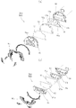
(可動演出装置)
図7、図8、図13〜図15に示すように、前記可動演出装置40は、設置部材22の背面板23aに取り付けられる可動ベース(ベース)44と、この可動ベース44に配設された可動ガイド(ガイド)50により往復移動可能に支持された可動演出体42と、可動ベース44に変位可能に配設されて、可動演出体42に接続された可動アーム(アーム)52とを備えている。可動演出体42は、待機位置(図7(a)参照)とこの待機位置より下方の可動演出位置(図7(b)参照)との間で、可動ガイド50により上下方向に往復移動可能に支持されている。可動演出装置40は、待機位置にある可動演出体42を、枠状装飾体26における表示窓口26aの開口内側に臨む図柄表示装置17の画像表示部17aの上側(外側)に退避すると共に前記上枠装飾部37の後側に隠れるように配置して、待機位置では、可動演出体42が遊技盤20の前側から見えないようになっている(図2および図5(a)参照)。また、可動演出装置40は、可動演出位置にある可動演出体42を、画像表示部17aの前側に重なるように配置し、可動演出位置では、可動演出体42が遊技盤20の前側から視認可能になるよう構成される(図3および図4参照)。このように、可動演出装置40は、可動演出体42が図柄表示装置17の画像表示部17aに対して出没するように動作し、実施例では可動演出位置において可動演出体42が画像表示部17aにおける上下左右方向の中央部に配置される。
(Moving effect device)
As shown in FIGS. 7, 8, and 13 to 15, the movable effect device 40 is disposed on a movable base (base) 44 that is attached to the back plate 23 a of the installation member 22, and the movable base 44. A movable effect body 42 supported by a movable guide (guide) 50 so as to be able to reciprocate, and a movable arm (arm) 52 disposed on the movable base 44 and connected to the movable effect body 42 are provided. Yes. The movable effect body 42 can be reciprocated in the vertical direction by a movable guide 50 between a standby position (see FIG. 7A) and a movable effect position below the standby position (see FIG. 7B). It is supported. The movable effect device 40 retracts the movable effector 42 in the standby position to the upper side (outside) of the image display unit 17a of the symbol display device 17 facing the inside of the opening of the display window 26a in the frame-shaped decorative body 26 and the upper side. It arrange | positions so that it may hide behind the frame decoration part 37, and in the stand-by position, the movable production | presentation body 42 cannot be seen from the front side of the game board 20 (refer FIG. 2 and FIG. 5 (a)). In addition, the movable effect device 40 arranges the movable effect body 42 at the movable effect position so as to overlap the front side of the image display unit 17a, and the movable effect body 42 is visible from the front side of the game board 20 at the movable effect position. (See FIGS. 3 and 4). In this way, the movable effect device 40 operates so that the movable effect body 42 appears and disappears with respect to the image display unit 17a of the symbol display device 17. In the embodiment, the movable effect device 42 is moved to the image display unit 17a at the movable effect position. Is arranged at the center in the vertical and horizontal directions.
図9〜図11および図13に示すように、前記可動演出装置40は、可動アーム52に設けられた可動係合部(係合部)56と、この可動係合部56を支持して可動アーム52の姿勢を保つ可動支持部(支持部)58と、この可動支持部58を、可動アーム52の変位に伴う可動係合部56の移動経路に重なる第1状態と該移動経路から外れる第2状態とに切り替える切替手段60とを備えている。可動演出装置40は、切替手段60による可動支持部58の位置切り替えにより可動支持部58と可動係合部56とを係脱するよう構成され、可動支持部58が可動係合部56を支持することで、可動アーム52の姿勢を保って可動演出体42を適宜の位置とすると共に、可動支持部58が可動係合部56から外れることで、可動アーム52の姿勢変位を許容して可動演出体42の自重による変位が可能になる構成とされる(図17参照)。すなわち、可動演出装置40は、可動演出体42を待機位置とした可動アーム52の上昇姿勢(姿勢)で可動係合部56を支持する可動支持部58を、切替手段60により第2状態に切り替えることで、可動演出体42が自重により落下するよう構成されている。また、可動演出装置40は、可動演出位置にある可動演出体42に伴って下降姿勢となった可動アーム52の可動係合部56を、切替手段60による可動支持部58の第1状態から第2状態への切り替えにより押し上げて、可動演出体42を可動演出位置から待機位置に移動するよう構成されている。
As shown in FIGS. 9 to 11 and 13, the movable effect device 40 is movable while supporting a movable engagement portion (engagement portion) 56 provided on the movable arm 52 and the movable engagement portion 56. A movable support portion (support portion) 58 that maintains the posture of the arm 52, and a first state in which the movable support portion 58 overlaps the movement path of the movable engagement portion 56 accompanying the displacement of the movable arm 52, and a first state that deviates from the movement path. Switching means 60 for switching between two states is provided. The movable effect device 40 is configured to engage and disengage the movable support portion 58 and the movable engagement portion 56 by switching the position of the movable support portion 58 by the switching means 60, and the movable support portion 58 supports the movable engagement portion 56. Thus, while maintaining the posture of the movable arm 52, the movable effect body 42 is set to an appropriate position, and the movable support portion 58 is disengaged from the movable engagement portion 56, so that the posture displacement of the movable arm 52 is permitted. The body 42 can be displaced by its own weight (see FIG. 17). That is, the movable effect device 40 switches the movable support portion 58 that supports the movable engagement portion 56 in the raised posture (posture) of the movable arm 52 with the movable effect body 42 as the standby position by the switching means 60 to the second state. Thus, the movable effector 42 is configured to fall by its own weight. In addition, the movable effect device 40 moves the movable engagement portion 56 of the movable arm 52 that has been lowered with the movable effect body 42 at the movable effect position from the first state of the movable support portion 58 by the switching means 60. The movable effect body 42 is pushed up by switching to the two states and moved from the movable effect position to the standby position.
(可動ベース)
横長に形成された前記可動ベース44は、設置部材22における設置開口部22aの上部に配置して背面板23aの前面に取り付けられ(図6参照)、上部設置スペースSHに収容されて遊技盤20の前側から視認不能になっている(図5(a)参照)。図13に示すように、可動ベース44は、前側に開放した略トレイ状に形成された可動ベース基体45と、この可動ベース基体45の右側部前側に取り付けられ、可動ベース基体45との間に部材収容空間を画成する右可動ベース被覆体46と、可動ベース基体45の右側部前側に取り付けられ、可動ベース基体45との間にスペースを画成する左可動ベース被覆体47とを備えている。可動ベース44は、遊技盤20の左右方向中央部に対応する位置において右可動ベース被覆体46と左可動ベース被覆体47との間に可動ベース基体45が前方に露出するように構成されており、この可動ベース基体45の前側露出部分に前記可動ガイド50が配設されている(図7(b)および(c)参照)。また、可動ベース44は、左右の可動ベース被覆体46,47の間が、可動演出体42の左右幅より大きく形成されて、可動ベース被覆体46,47の前面と可動ベース基体45との前面とがなす後側へ凹んだベース段状部44aに、待機位置にある可動演出体42の後部が収容されるようになっている(図7(a)参照)。可動ベース基体45と右可動ベース被覆体46との間の右部材収容空間には、可動アーム52の一端部が収容され、該可動アーム52の一端部が可動ベース基体45に対して前後方向の軸周りに回動可能に支持されている。可動ベース44において右部材収容空間を画成する下壁および前記ベース段状部44aに臨む左壁には、可動アーム52が挿通および変位可能な挿通開口が開設され、この挿通開口を介して可動アーム52の他端部が右部材収容空間の外側へ延出するようになっている。また、右可動ベース被覆体46の前側には、後述する可動モータ(駆動手段)64の設置台となるモータ設置体48が配設されている。モータ設置体48は、後方に開放した略トレイ形状に形成され、切替手段60(後述の切替連繋部62)の前側を覆うようになっている。
(Movable base)
The movable base 44 formed in a horizontally long shape is disposed above the installation opening 22a of the installation member 22 and attached to the front surface of the back plate 23a (see FIG. 6), and is accommodated in the upper installation space SH to be used in the game board 20. Is not visible from the front side (see FIG. 5A). As shown in FIG. 13, the movable base 44 is attached to a movable base base 45 formed in a substantially tray shape opened to the front side and the right side front side of the movable base base 45, and between the movable base base 45. A right movable base covering body 46 that defines a member housing space; and a left movable base covering body 47 that is attached to the front side of the right side of the movable base base body 45 and defines a space between the movable base base body 45. Yes. The movable base 44 is configured such that the movable base body 45 is exposed forward between the right movable base covering body 46 and the left movable base covering body 47 at a position corresponding to the central portion in the left-right direction of the game board 20. The movable guide 50 is disposed in the front exposed portion of the movable base body 45 (see FIGS. 7B and 7C). The movable base 44 is formed between the left and right movable base covering bodies 46 and 47 to be larger than the left and right width of the movable rendering body 42, and the front surface of the movable base covering bodies 46 and 47 and the front surface of the movable base base body 45. The rear portion of the movable effector 42 at the standby position is accommodated in the base stepped portion 44a that is recessed toward the rear side (see FIG. 7A). One end of the movable arm 52 is accommodated in the right member accommodation space between the movable base base 45 and the right movable base covering 46, and the one end of the movable arm 52 extends in the front-rear direction with respect to the movable base base 45. It is supported so as to be rotatable around an axis. An insertion opening through which the movable arm 52 can be inserted and displaced is formed in the lower wall defining the right member accommodation space in the movable base 44 and the left wall facing the base stepped portion 44a, and the movable base 52 is movable through the insertion opening. The other end of the arm 52 extends outside the right member accommodation space. Further, a motor installation body 48 serving as an installation base for a movable motor (driving means) 64 described later is disposed on the front side of the right movable base covering body 46. The motor installation body 48 is formed in a substantially tray shape opened rearward, and covers the front side of the switching means 60 (a switching connection portion 62 described later).
(可動ガイド)
前記可動ガイド50は、可動ベース44に設けられたベース段状部44aと可動演出体42の後面との間に配設され、可動ベース44に対して可動演出体42を上下方向に往復移動可能に支持している。実施例の可動ガイド50は、複数の可動レール部50aをボールベアリングを介して摺動可能に組み合わせたスライドレールが用いられ、可動ベース44のベース段状部44aに上下方向に延在するように配設された可動レール部50aに対して、可動演出体42の後面に上下方向に延在するように配設された可動レール部50aが上下方向に移動可能になっている。また、実施例の可動ガイド50は、可動ベース44に配設された可動レール部50aと、可動演出体42に配設された可動レール部50aとの間に、更に別の可動レール部50aが介在する多段式であり、可動ベース44に対する可動演出体42の移動可能距離を大きくし得ると共に、可動演出体42を待機位置にした際に、可動ガイド50の上下寸法をコンパクトにできる。ここで、可動演出体42は、該可動演出体42の左右方向中央より右側方に偏った部位に可動アーム52の他端部が接続されると共に、該可動演出体42の左右方向中央より左側方に偏った部位で可動ガイド50に支持されている。
(Movable guide)
The movable guide 50 is disposed between a base stepped portion 44 a provided on the movable base 44 and the rear surface of the movable rendering body 42, and can move the movable rendering body 42 back and forth with respect to the movable base 44. I support it. The movable guide 50 of the embodiment uses a slide rail in which a plurality of movable rail portions 50a are slidably combined via ball bearings, and extends vertically to the base stepped portion 44a of the movable base 44. The movable rail portion 50a disposed so as to extend in the vertical direction on the rear surface of the movable effect body 42 is movable in the vertical direction with respect to the disposed movable rail portion 50a. Further, in the movable guide 50 of the embodiment, another movable rail portion 50 a is provided between the movable rail portion 50 a disposed on the movable base 44 and the movable rail portion 50 a disposed on the movable effect body 42. It is a multistage system, and the movable distance of the movable effector 42 relative to the movable base 44 can be increased, and the vertical dimension of the movable guide 50 can be made compact when the movable effector 42 is set to the standby position. Here, the movable effector 42 has the other end of the movable arm 52 connected to a portion that is biased to the right side from the center in the left-right direction of the movable effector 42 and the left side of the center of the movable effector 42 in the left-right direction. It is supported by the movable guide 50 at a portion biased in the direction.
(可動アーム)
図13に示すように、前記可動アーム52は、その長手方向の一端部が可動ベース44に回動可能に支持されると共に、その長手方向の他端部が前記可動演出体42に接続されている。より具体的には可動アーム52は、可動ベース基体45の右側部下側に設けられた孔状の軸受部45aに該可動アーム52の一端部に開設された軸孔52aを介して支軸52bを嵌合することで、可動ベース基体45に対して回動可能に軸支される。可動アーム52は、可動ベース44に対する支持部分(一端部)から、可動ベース基体45の前側に重なるように左方に延在する上昇姿勢で、回動端部(他端部)が右部材収容空間を画成する左壁からベース段状部44aに延出し、この回動端部に接続された前記可動演出体42を待機位置で保持するようになっている。また、可動アーム52は、可動ベース44に対する支持部分から、左側へ向かうにつれて下方傾斜するように延在する下降姿勢で、回動端部が右部材収容空間を画成する下壁から可動ベース44の下側に延出し、この回動端部に接続された前記可動演出体42の可動演出位置への配置を許容するようになっている。
(Movable arm)
As shown in FIG. 13, one end of the movable arm 52 is rotatably supported by the movable base 44, and the other end of the longitudinal direction is connected to the movable effector 42. Yes. More specifically, the movable arm 52 is configured such that a support shaft 52b is connected to a hole-like bearing portion 45a provided on the lower side of the right side of the movable base base 45 via a shaft hole 52a provided at one end of the movable arm 52. By fitting, it is pivotally supported with respect to the movable base substrate 45. The movable arm 52 is in a rising posture extending leftward from the support portion (one end portion) for the movable base 44 so as to overlap the front side of the movable base substrate 45, and the rotating end portion (the other end portion) accommodates the right member. The movable effect body 42 that extends from the left wall that defines the space to the base stepped portion 44a and is connected to the rotating end portion is held at the standby position. In addition, the movable arm 52 is in a lowered posture that extends downwardly from the support portion for the movable base 44 toward the left side, and the movable base 44 extends from the lower wall that defines the right member accommodation space. The movable effect body 42 connected to the rotating end portion is allowed to be arranged at the movable effect position.
図9に示すように、前記可動アーム52は、上昇姿勢において、可動ベース44への支持部分から上方に延在する第1アーム部52cと、この第1アーム部52cから屈曲して左方に延在する第2アーム部52dとを備え、正面視で全体として略L字状に形成されている。可動アーム52は、第1アーム部52cと比べて第2アーム部52dが長く形成されている。そして、可動アーム52は、上昇姿勢において左右方向に延在する第2アーム部52dが、下降姿勢において下方傾斜するようになっている。なお、第2アーム部52dは、可動アーム52の上昇姿勢において、途中から回動端部に向かうにつれて上方(第1アーム部52cと反対側)傾斜するように形成された上方傾斜部分を備えている。
As shown in FIG. 9, the movable arm 52 is in a raised position, and a first arm portion 52c extending upward from a support portion for the movable base 44, and a left side bent from the first arm portion 52c. The second arm portion 52d extends, and is formed in an approximately L shape as a whole in a front view. The movable arm 52 has a second arm portion 52d that is longer than the first arm portion 52c. The movable arm 52 is configured such that the second arm portion 52d extending in the left-right direction in the raised posture is inclined downward in the lowered posture. The second arm portion 52d includes an upper inclined portion formed so as to be inclined upward (opposite to the first arm portion 52c) from the middle toward the turning end portion in the ascending posture of the movable arm 52. Yes.
図13に示すように、前記可動アーム52は、平板状の可動アーム後体53と、この可動アーム後体53の前側に取り付けられ、後方に開放した略トレイ形状に形成された可動アーム前体54とから構成されている。可動アーム52は、可動アーム前体54とこの可動アーム前体54の後方開口を塞ぐように取り付けた可動アーム後体53との間に、設置部材22側から可動演出体42に配設される電気部品(後述の可動発光手段91や装飾モータ77)に繋がる配線を収容可能になっている。
As shown in FIG. 13, the movable arm 52 includes a flat movable arm rear body 53 and a movable arm front body which is attached to the front side of the movable arm rear body 53 and has a substantially tray shape opened rearward. 54. The movable arm 52 is disposed on the movable effector 42 from the installation member 22 side between the movable arm front body 54 and the movable arm rear body 53 attached so as to close the rear opening of the movable arm front body 54. Wiring connected to electrical components (movable light emitting means 91 and decorative motor 77 described later) can be accommodated.
(可動係合部)
図9(a)および図10(a)に示すように、前記可動係合部56は、可動アーム52(可動アーム前体54)の前面に前方に突出するように設けられ、可動アーム52の上昇姿勢で左右方向に延在する庇状に形成されている。可動係合部56は、可動アーム52における第2アーム部52dの上縁部に設けられ、該第2アーム部52dにおいて回動端部側に偏倚した位置に配置されている。また、可動係合部56は、第2アーム部52dにおける前記上方傾斜部分の屈曲部から右方へ直線的に延在するように、可動ベース前体54に一体的に形成されている。そして、可動係合部56は、可動アーム52の上昇姿勢と下降姿勢との間の回動変位に伴って、可動ベース44における右部材収容空間内において上下に変位するようになっている。
(Movable engagement part)
As shown in FIGS. 9A and 10A, the movable engaging portion 56 is provided so as to protrude forward from the front surface of the movable arm 52 (movable arm front body 54). It is formed in a bowl shape extending in the left-right direction in a rising posture. The movable engaging portion 56 is provided at the upper edge portion of the second arm portion 52d of the movable arm 52, and is disposed at a position biased toward the rotating end portion in the second arm portion 52d. The movable engagement portion 56 is integrally formed with the movable base front body 54 so as to extend linearly rightward from the bent portion of the upward inclined portion of the second arm portion 52d. The movable engagement portion 56 is displaced up and down in the right member accommodation space in the movable base 44 in accordance with the rotational displacement between the rising posture and the lowering posture of the movable arm 52.
(切替手段)
図13に示すように、前記切替手段60は、右可動ベース被覆体46に前後方向の軸周りに回転可能に軸支される回転体であり、駆動手段としての可動モータ64により回転される。切替手段60は、円盤形状に形成された切替本体部61と、この切替本体部61より小径の円盤状に形成され、切替本体部61の前側に該切替本体部61と同軸的に配設された切替連繋部62とを備え、切替本体部61と切替連繋部62とが右可動ベース被覆体46の前板を前後に挟んで共通の支軸により軸支されている。ここで、切替手段60は、切替本体部61が右部材収容空間に収容されて可動アーム52の第2アーム部52d(可動係合部56)の前側に重なるように配置されると共に、切替連繋部62が右可動ベース被覆体46の前板に後方へ凹むように形成された連繋収容凹部46aの前側に収容される。切替連繋部62の周面には、後述する可動モータ64の可動ピニオン65に噛み合う連繋歯部62aが形成されている。
(Switching means)
As shown in FIG. 13, the switching means 60 is a rotating body that is rotatably supported by the right movable base covering body 46 around an axis in the front-rear direction, and is rotated by a movable motor 64 as a driving means. The switching means 60 is formed in a switching body portion 61 formed in a disk shape and a disk shape having a smaller diameter than the switching body portion 61, and is disposed coaxially with the switching body portion 61 on the front side of the switching body portion 61. The switching body 62 and the switching body 62 are pivotally supported by a common support shaft with the front plate of the right movable base covering body 46 sandwiched between the front and rear. Here, the switching means 60 is disposed so that the switching main body 61 is accommodated in the right member accommodating space and overlaps the front side of the second arm portion 52d (movable engagement portion 56) of the movable arm 52, and is switched and connected. The part 62 is accommodated on the front side of the continuous accommodating recess 46 a formed to be recessed backward in the front plate of the right movable base covering body 46. On the peripheral surface of the switching connecting portion 62, a connecting tooth portion 62a that engages with a movable pinion 65 of a movable motor 64 described later is formed.
前記可動モータ64は、後方に開放した略トレイ形状に形成されたモータ設置体48の前面に、出力軸を後方へ向けた姿勢で取り付けられ、該モータ設置体48の後方へ突出する出力軸の先端に可動ピニオン65が固定されている(図13参照)。可動ピニオン65は、モータ設置体48を右可動ベース被覆体46の前面に取り付けた際に、連繋収容凹部46aに繋がるように右可動ベース被覆体46に前後に貫通形成された連繋開口46bの内側に収容されると共に、連繋開口46bに臨む切替連繋部62の周面に設けられた連繋歯部62aに噛み合うようになっている。このように、切替手段60は、可動モータ64の駆動により回転する可動ピニオン65に伴って切替連繋部62が回転することで、可動アーム52に臨む切替本体部61が回転するようになっている。ここで、切替手段60は、可動アーム52の上昇姿勢および下降姿勢との間の上下変位に伴う可動係合部56の移動経路に対して、切替本体部61における回転中心より左側領域の少なくとも一部が前側に重なり、切替本体部61における回転中心より右側領域の少なくとも一部が前記移動経路の前側に重ならないように構成される(図17参照)。
The movable motor 64 is attached to the front surface of the motor installation body 48 formed in a substantially tray shape that is opened rearward with the output shaft facing backward, and the output shaft that protrudes rearward of the motor installation body 48. A movable pinion 65 is fixed to the tip (see FIG. 13). When the motor installation body 48 is attached to the front surface of the right movable base covering body 46, the movable pinion 65 is located inside the connecting opening 46b formed through the right movable base covering body 46 so as to be connected to the front and rear of the right movable base covering body 46a. And is engaged with a connecting tooth portion 62a provided on the peripheral surface of the switching connecting portion 62 facing the connecting opening 46b. As described above, the switching means 60 is configured such that the switching main body 61 facing the movable arm 52 is rotated by the rotation of the switching link 62 along with the movable pinion 65 that is rotated by driving the movable motor 64. . Here, the switching means 60 has at least one of the left side region from the rotation center of the switching main body 61 with respect to the movement path of the movable engaging portion 56 accompanying the vertical displacement between the rising posture and the lowering posture of the movable arm 52. The part overlaps the front side, and at least a part of the right region from the rotation center in the switching main body part 61 is configured not to overlap the front side of the movement path (see FIG. 17).
(可動支持部)
図17に示すように、前記可動支持部58は、切替手段60における切替本体部61の回転中心から半径方向外側に偏倚した偏芯位置に設けられ、切替手段60の回転に伴って可動係合部56に対する位置が第1状態と第2状態とに切り替わるように構成される。また、可動支持部58は、切替本体部61の後面から後方へ突出し、その後端が可動係合部56の前縁よりも後方に位置する一方で、第2アーム部52dの前面に当接しないように設定されている(図9(c)および図10(c)参照)。可動支持部58は、切替手段60における切替本体部61に突設された支持軸部(軸部)58aと、この支持軸部58aに回転可能に配設されて、可動係合部56に当接する支持円筒体(円筒体)58bとを備え(図13(b)参照)、可動係合部56の延在方向に沿って可動支持部58が変位する際に支持円筒体58bが回転することで、可動係合部56と可動支持部58との摺動抵抗を軽減している。可動支持部58は、切替手段60の回転に伴い切替本体部61の回転中心軸周りに回転変位し、切替本体部61の最上部(可動支持部58の回転軌跡における最上位)に位置する際に、可動演出体42を待機位置とする可動アーム52の上昇姿勢で可動係合部56を支持するように構成されている(図9および図17(a)参照)。そして、可動支持部58は、切替手段60の回転に伴い時計回りに回転変位して切替本体部61における回転中心より右側領域に至ることで、可動アーム52の姿勢変位に伴う可動係合部56の移動経路上から外れる(図17(b)および(c))。
(Moving support)
As shown in FIG. 17, the movable support portion 58 is provided at an eccentric position that is biased radially outward from the rotation center of the switching body portion 61 in the switching means 60, and is movablely engaged as the switching means 60 rotates. The position with respect to the part 56 is configured to switch between the first state and the second state. In addition, the movable support portion 58 protrudes rearward from the rear surface of the switching main body portion 61, and the rear end thereof is positioned rearward of the front edge of the movable engagement portion 56, but does not contact the front surface of the second arm portion 52d. (See FIG. 9 (c) and FIG. 10 (c)). The movable support portion 58 is provided on a support shaft portion (shaft portion) 58a projecting from the switching main body portion 61 of the switching means 60, and is rotatably disposed on the support shaft portion 58a. A supporting cylindrical body (cylindrical body) 58b (see FIG. 13B), and the supporting cylindrical body 58b rotates when the movable supporting portion 58 is displaced along the extending direction of the movable engaging portion 56. Thus, the sliding resistance between the movable engagement portion 56 and the movable support portion 58 is reduced. The movable support portion 58 is rotationally displaced around the rotation center axis of the switching main body portion 61 with the rotation of the switching means 60 and is positioned at the uppermost portion of the switching main body portion 61 (the uppermost position in the rotation trajectory of the movable support portion 58). In addition, the movable engagement portion 56 is supported with the movable arm 52 in the raised posture with the movable effector 42 as the standby position (see FIGS. 9 and 17A). The movable support portion 58 is rotated and displaced clockwise with the rotation of the switching means 60 and reaches the right region from the rotation center of the switching main body portion 61, so that the movable engagement portion 56 associated with the displacement of the movable arm 52 is obtained. (B) and (c) in FIG.
前記可動支持部58は、切替手段60の回転に伴い時計回りに回転変位して切替本体部における回転中心より左側領域に至ることで、可動アーム52の姿勢変位に伴う可動係合部56の移動経路上に重なるようになっている(図10、図17(d)および(e)参照)。すなわち、可動支持部58は、切替本体部61の回転中心より左側領域から右側領域上部に位置する所定範囲で、可動係合部56の下側(可動アーム52の上昇姿勢から下方姿勢への姿勢変位に伴う可動係合部56の移動方向前側)に位置する第1状態になり、切替本体部61の回転中心より右側領域から左側領域下部に位置する所定範囲で、可動係合部56の下側(可動アーム52の上昇姿勢から下方姿勢への姿勢変位に伴う可動係合部の移動方向前側)から外れて第2状態になるように構成される。換言すると、可動係合部56は、切替手段60の回転に伴い可動支持部58が切替本体部61の最下部から最上部(可動支持部58の回転軌跡における最下位から最上位)に変位するまでの左右方向の変位範囲の上方に少なくとも延在するよう形成されている。このように、可動支持部58は、可動モータ64の回転駆動による切替手段60の回転により、可動係合部56を支持可能な第1状態と可動係合部56の支持を解除した第2状態とに切り替えられる。
The movable support portion 58 rotates clockwise as the switching means 60 rotates and reaches the left region from the center of rotation in the switching main body portion, so that the movable engagement portion 56 moves in accordance with the displacement of the movable arm 52. It overlaps on the route (see FIG. 10, FIG. 17 (d) and (e)). That is, the movable support portion 58 is positioned below the movable engagement portion 56 (the posture from the raised posture of the movable arm 52 to the lower posture) within a predetermined range located from the left region to the upper right region from the rotation center of the switching main body portion 61. The first state is located on the front side in the movement direction of the movable engagement portion 56 due to the displacement, and is below the movable engagement portion 56 within a predetermined range located from the right region to the lower left region from the rotation center of the switching main body 61. It is configured so as to be disengaged from the side (the front side in the moving direction of the movable engagement portion accompanying the posture displacement of the movable arm 52 from the raised posture to the lower posture). In other words, in the movable engagement portion 56, the movable support portion 58 is displaced from the lowermost portion of the switching main body portion 61 to the uppermost portion (from the lowest position to the highest position in the rotation trajectory of the movable support portion 58) with the rotation of the switching means 60. It is formed so as to extend at least above the left-right displacement range. As described above, the movable support portion 58 has the first state in which the movable engagement portion 56 can be supported and the second state in which the support of the movable engagement portion 56 is released by the rotation of the switching means 60 by the rotational drive of the movable motor 64. And can be switched.
前記切替手段60は、可動演出体42を待機位置とした可動アーム52の上昇姿勢で可動係合部56を支持する第1状態にある可動支持部58を、切替本体部61の時計回りの回転に伴い第2状態に切り替え、可動支持部58による可動係合部56の支持を解除するようになっている(図17(a)および(b)参照)。これにより、可動支持部58に邪魔されることなく可動アーム52の下方へ向けた姿勢変位が許容され、可動演出体42が待機位置から可動演出位置に向けて自重により落下するのにつれて、可動アーム52が下降姿勢に姿勢変位される(図17(c)参照)。切替手段60は、切替本体部61の時計回りの回転により、切替本体部61の右側領域を上方から下方へ向けて円弧状軌跡で可動支持部58を第2状態で変位させた後に、可動支持部58を切替本体部61の左側領域に到来させることで、該可動支持部58を、第2状態から、下降姿勢にある可動アーム52に伴って切替本体部61の左側領域下部の後側に斜めに延在する可動係合部56の下側に位置する第1状態に切り替える(図17(d)参照)。そして、切替手段60は、切替本体部61の時計回り回転により、第1状態にある可動支持部58を、切替本体部61の左側領域において下方から上方へ向けて円弧状軌跡で上方変位するようになっている。すなわち、可動支持部58は、可動演出体42が可動演出位置にある可動アーム52の可動係合部56を、切替手段60による第1状態での変位により押し上げるように構成され、下降姿勢から上昇姿勢へ向けて姿勢変位する可動アーム52に伴って可動演出体42が可動演出位置から待機位置に移動される。このように、可動演出装置40は、切替手段60を一方向(実施例では時計回り)に回転することで、可動支持部58を第1状態と第2状態とに切り替え可能であり、可動支持部58の第1状態と第2状態との切り替えにより、可動演出体42を待機位置から落下させると共に可動演出体42を可動演出位置から待機位置に復帰させる一連の動作を行い得るように構成される。
The switching means 60 rotates the movable support portion 58 in the first state in which the movable engagement portion 56 is supported in the raised posture of the movable arm 52 with the movable effect body 42 as the standby position, and the switching body portion 61 rotates clockwise. Accordingly, the second state is switched to release the support of the movable engagement portion 56 by the movable support portion 58 (see FIGS. 17A and 17B). Accordingly, the downward displacement of the movable arm 52 is allowed without being obstructed by the movable support portion 58, and the movable arm 42 is moved by its own weight from the standby position toward the movable effect position as the movable arm 42 falls. 52 is displaced to a lowered posture (see FIG. 17C). The switching means 60 displaces the movable support portion 58 in the second state with an arcuate path from the upper side to the lower side by rotating the switching body portion 61 in the clockwise direction. By bringing the portion 58 into the left region of the switching body 61, the movable support 58 is moved from the second state to the rear of the lower portion of the left region of the switching body 61 with the movable arm 52 in the lowered posture. It switches to the 1st state located below the movable engaging part 56 extended diagonally (refer FIG.17 (d)). Then, the switching means 60 causes the movable support portion 58 in the first state to be displaced upward in a circular arc locus from the lower side to the upper side in the left region of the switching main body portion 61 by the clockwise rotation of the switching main body portion 61. It has become. That is, the movable support portion 58 is configured to push up the movable engagement portion 56 of the movable arm 52 in which the movable effect body 42 is in the movable effect position by the displacement in the first state by the switching means 60, and rises from the lowered posture. The movable effector 42 is moved from the movable effect position to the standby position along with the movable arm 52 that is displaced toward the attitude. Thus, the movable effect device 40 can switch the movable support portion 58 between the first state and the second state by rotating the switching means 60 in one direction (clockwise in the embodiment), and the movable support device By switching between the first state and the second state of the unit 58, a series of operations for dropping the movable effect body 42 from the standby position and returning the movable effect body 42 from the movable effect position to the standby position can be performed. The
図9および図10に示すように、前記可動演出装置40には、可動演出体42の位置を検出する可動検出手段66が、右可動ベース被覆体46に設けられている。実施例の可動検出手段66は、前後に対向配置された発光部と受光部を有するフォトセンサであり、発光部と受光部との間を切替手段60における切替本体部61の外周縁が通るように配設されている。切替本体部61は、外周縁の一部を切り欠いて形成された可動検出部61aを有し、可動支持部58が切替本体部61の最上位(可動演出体42の待機位置に対応)にあるときに、可動検出部61aが可動検出手段66における発光部と受光部との間に位置し(図9(a)参照)、可動支持部58が切替本体部61の最上位から外れた位置にあるときに、切替本体部61の外周縁が発光部と受光部との間に位置するようになっている(図10(a)参照)。
As shown in FIGS. 9 and 10, the movable effect device 40 is provided with a movable detection means 66 for detecting the position of the movable effect body 42 in the right movable base covering 46. The movable detection means 66 of the embodiment is a photosensor having a light emitting part and a light receiving part that are opposed to each other in the front-rear direction so that the outer peripheral edge of the switching main body 61 in the switching means 60 passes between the light emitting part and the light receiving part. It is arranged. The switching main body 61 has a movable detection portion 61a formed by cutting out a part of the outer peripheral edge, and the movable support portion 58 is at the uppermost position of the switching main body 61 (corresponding to the standby position of the movable effector 42). In some cases, the movable detector 61a is located between the light emitting part and the light receiver in the movable detector 66 (see FIG. 9A), and the movable support part 58 is displaced from the uppermost position of the switching body 61. , The outer peripheral edge of the switching main body 61 is positioned between the light emitting part and the light receiving part (see FIG. 10A).
(ストッパ)
図9および図10に示すように、前記可動演出装置40は、可動演出体42の待機位置からの落下に伴って姿勢変位する可動アーム52を、該可動演出体42の可動演出位置に対応する下降姿勢で受け止める可動ストッパ(ストッパ)68を備えている。可動ストッパ68は、可動ベース基体45の右側下部前面に配設され、右部材収容空間に収容されている。また、可動ストッパ68は、可動アーム52の上昇姿勢から下降姿勢へ向けた姿勢変位方向前側に位置して、該可動アーム52を支持する軸受部45aの左側(該軸受部45aからの可動アーム52の延在方向)に隣接配置されている。ここで、可動ストッパ68は、可動演出体42の待機位置に対応する可動アーム52の上昇姿勢において、第1アーム部52aの左側に該第1アーム部52aから離間して配置されるると共に、第2アーム部52bの下側に該第2アーム部52bから離間して配置される。また、可動ストッパ68は、可動演出体42の可動演出位置に対応する可動アーム52の下降姿勢において、第1アーム部52aと第2アーム部52bとの屈曲部下側に位置するように設けられている。
(Stopper)
As shown in FIG. 9 and FIG. 10, the movable effect device 40 corresponds to the movable effect position of the movable effector 42, the movable arm 52 whose posture is displaced as the movable effector 42 drops from the standby position. A movable stopper (stopper) 68 that is received in a lowered posture is provided. The movable stopper 68 is disposed on the lower right front surface of the movable base 45 and is accommodated in the right member accommodation space. The movable stopper 68 is positioned on the front side in the posture displacement direction of the movable arm 52 from the rising posture to the lowering posture, and is located on the left side of the bearing portion 45a that supports the movable arm 52 (the movable arm 52 from the bearing portion 45a). In the extending direction). Here, the movable stopper 68 is disposed on the left side of the first arm portion 52a so as to be separated from the first arm portion 52a in the raised posture of the movable arm 52 corresponding to the standby position of the movable effector 42, and The second arm portion 52b is disposed below the second arm portion 52b below the second arm portion 52b. Further, the movable stopper 68 is provided so as to be positioned below the bent portion of the first arm portion 52a and the second arm portion 52b in the lowered posture of the movable arm 52 corresponding to the movable effect position of the movable effect body 42. Yes.
図10(a)に示すように、前記可動ストッパ68は、下降姿勢において支持部分から左方へ向かうにつれて上方傾斜するように延在する第1アーム部52aの壁面に合わせて、下方から上方へ向かうにつれて左側に傾く第1受面68aと、下降姿勢において屈曲部分から左方へ向かうにつれて下方傾斜するように延在する第2アーム部68bの壁面に合わせて、下方から上方へ向かうにつれて右側に傾く第2受面68bとを備えている。そして、可動ストッパ68は、可動アーム52の下降姿勢において、第1受面68aにより第1アーム部52aを受け止めると共に第2受面68bにより第2アーム52bを受け止め可能になっている。ここで、第1受面68aおよび第2受面68bは、ゴム等の弾力性を有する緩衝部材で構成されており、可動アーム52を受け止める際の衝撃を吸収して、可動アーム52が受面68a,68bに当たった際にはね返らないようにしている。なお、可動ストッパ68は、第1アーム部68aと第2アーム部68bとの間の屈曲部分に形成されたテーパ壁面に合わせて、略水平に形成された逃げ面68cを有している。
As shown in FIG. 10 (a), the movable stopper 68 extends from below to above in accordance with the wall surface of the first arm portion 52a extending upwardly from the support portion toward the left in the lowered posture. The first receiving surface 68a that tilts to the left as it goes and the wall surface of the second arm portion 68b that extends so as to tilt to the left from the bent portion in the lowered posture, and to the right as it goes from below to above. And an inclined second receiving surface 68b. The movable stopper 68 is capable of receiving the first arm portion 52a by the first receiving surface 68a and the second arm 52b by the second receiving surface 68b when the movable arm 52 is lowered. Here, the first receiving surface 68a and the second receiving surface 68b are made of a cushioning member having elasticity such as rubber, and absorb the impact when receiving the movable arm 52 so that the movable arm 52 receives the surface. When it hits 68a, 68b, it does not rebound. The movable stopper 68 has a clearance surface 68c formed substantially horizontally in accordance with a tapered wall surface formed at a bent portion between the first arm portion 68a and the second arm portion 68b.
図9(b)および図10(b)に示すように、前記可動演出体42には、可動アーム52の回動端部が回動可能に接続されている。具体的には、可動アーム52の回動端部には、該可動アーム52(第2アーム部52b)の延在方向に長手が延在する可動接続孔55が開設され、可動演出体42の後面から後方へ突出する可動接続軸70を可動接続孔55に係合させることで、可動演出体42と可動アーム52とが接続されている。上下方向だけでなく左右方向の変位成分を有する可動アーム52の回動端部の回動変位に対して、可動演出体42は、可動ガイド50に直線的に上下移動するように支持されているが、可動接続軸70が可動接続孔55の長手に沿って位置ズレが許容されている。これにより、待機位置から可動演出位置への可動演出体42の落下が、可動アーム52により妨げられることはなく、下降姿勢から上昇姿勢へ回動する可動アーム52に伴って、可動演出体42を可動演出位置から待機位置へ円滑に上昇させることができる。また、可動演出体42は、可動ガイド50に支持されて、可動アーム52の姿勢変位に伴って左右に傾くことなくそのままの姿勢で上下方向に往復移動するように構成されている(図7参照)。ここで、可動演出体42は、後面における左右方向中央より右側に偏倚した部位の上部に可動アーム52の回動端部が接続されており、後面における左右方向中央より左側に偏倚した部位で可動ガイド50により支持されている。可動演出体42において、可動アーム52の接続部位と可動ガイド50の支持部位とが左右に振り分けてあり、すなわち、可動アーム52の支持部分に近い側に該可動アーム52が接続しているのに対して、可動アーム52の支持部分から遠い側で可動ガイド50により支持されている。なお、実施例の可動演出体42では、該可動演出体42の右側に配設された後述する装飾モータ(駆動手段)77の上側で、可動アーム52の回動端部が接続されている(図9(b)および図10(b)参照)。
As shown in FIGS. 9B and 10B, the movable effector 42 is pivotally connected to the movable end 52 of the movable arm 52. Specifically, a movable connection hole 55 having a longitudinal extension in the extending direction of the movable arm 52 (second arm portion 52 b) is opened at the rotating end of the movable arm 52, The movable effector 42 and the movable arm 52 are connected by engaging the movable connection shaft 70 protruding rearward from the rear surface with the movable connection hole 55. The movable effector 42 is supported by the movable guide 50 so as to move up and down linearly with respect to the rotational displacement of the rotational end of the movable arm 52 having a displacement component in the horizontal direction as well as the vertical direction. However, the displacement of the movable connection shaft 70 is allowed along the length of the movable connection hole 55. Thereby, the fall of the movable effect body 42 from the standby position to the movable effect position is not hindered by the movable arm 52, and the movable effect body 42 is moved along with the movable arm 52 that rotates from the lowered position to the raised position. It is possible to smoothly raise the movable effect position to the standby position. Further, the movable effector 42 is supported by the movable guide 50 and is configured to reciprocate in the vertical direction in the same posture without tilting left and right as the posture of the movable arm 52 is changed (see FIG. 7). ). Here, the movable effector 42 is connected to the upper end of a portion biased to the right from the center in the left-right direction on the rear surface, and is movable at a portion biased to the left from the center in the left-right direction on the rear surface. Supported by a guide 50. In the movable effector 42, the connection part of the movable arm 52 and the support part of the movable guide 50 are distributed to the left and right, that is, the movable arm 52 is connected to the side closer to the support part of the movable arm 52. On the other hand, it is supported by the movable guide 50 on the side far from the support portion of the movable arm 52. In the movable effect body 42 of the embodiment, the rotating end of the movable arm 52 is connected to the upper side of a decorative motor (drive means) 77 (described later) disposed on the right side of the movable effect body 42 ( (See FIG. 9B and FIG. 10B).
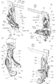
(可動演出体)
図9〜図11に示すように、前記可動演出体42は、前記可動ガイド50および可動アーム52に支持される可動基部72と、この可動基部72の前側に該可動基部72に対して変位可能に配設された可動装飾部86とを備えている。実施例の可動演出体42は、可動基部72の前側上部と覆う上部可動装飾部86Aと、可動基部72の前側下部を覆う下部可動装飾部86Bとの2つを有し、これらの可動装飾部86A,86Bが可動基部72に対して左右方向(可動演出体42における待機位置と可動演出位置との間の移動方向と交差する方向)に移動するように構成されている。また、可動演出体42は、上下2つの可動装飾部86A,86Bが互いに相反する向きに進退移動するよう構成され、各可動装飾部86A,86Bは、可動基部72の前側に重なった基本位置(図7および図16(a)参照)と、可動基部72の側縁(外縁)から側方(外方)へ延出するように可動基部72からずれた作動位置(図8および図16(b)参照)との間で左右方向に移動するようになっている。ここで、上部可動装飾部86Aは、基本位置から右方へ移動して作動位置になり、該作動位置において可動基部72の右側縁から右方へ延出するようになっている。これに対して、下部可動装飾部86Bは、基本位置から左方へ移動して作動位置になり、該作動位置において可動基部72の左側縁から左方へ延出するようになっている。可動演出体42は、上下の可動装飾部86A,86Bが可動基部72の前側に整合した基本位置において、上部可動装飾部86Aの下縁と下部可動装飾体86Bの上縁とが互いに整合して、両可動装飾部86A,86Bにより略円形の意匠形状が形成される。可動演出体42は、上下の可動装飾部86A,86Bの夫々が作動位置に移動した際に、上部可動装飾部86Aと下部可動装飾部86Bとが左右にずれて、基本位置で両可動装飾部86A,86Bにより形成されていた意匠形状が上下に分断された形状になる。
(Moveable director)
As shown in FIGS. 9 to 11, the movable effector 42 can be displaced with respect to the movable base 72 on the front side of the movable base 72 and the movable base 72 supported by the movable guide 50 and the movable arm 52. And a movable decorative portion 86 disposed on the surface. The movable effector 42 of the embodiment has two parts, an upper movable decorative part 86A that covers the front upper part of the movable base 72, and a lower movable decorative part 86B that covers the front lower part of the movable base 72, and these movable decorative parts. 86 </ b> A and 86 </ b> B are configured to move in the left-right direction with respect to the movable base 72 (direction intersecting the moving direction between the standby position and the movable effect position in the movable effect body 42). The movable effector 42 is configured such that the upper and lower movable decorative portions 86A and 86B move forward and backward in directions opposite to each other, and each movable decorative portion 86A and 86B overlaps the front side of the movable base 72 ( 7 and FIG. 16 (a)), and an operating position shifted from the movable base 72 so as to extend from the side edge (outer edge) of the movable base 72 to the side (outward) (FIGS. 8 and 16 (b)). )))) In the horizontal direction. Here, the upper movable decorative portion 86A moves rightward from the basic position to the operating position, and extends rightward from the right edge of the movable base 72 at the operating position. On the other hand, the lower movable decorative portion 86B moves leftward from the basic position to the operating position, and extends to the left from the left edge of the movable base 72 at the operating position. At the basic position where the upper and lower movable decorative portions 86A and 86B are aligned with the front side of the movable base 72, the movable effector 42 is aligned with the lower edge of the upper movable decorative portion 86A and the upper edge of the lower movable decorative body 86B. A substantially circular design shape is formed by the two movable decorative portions 86A and 86B. When the upper and lower movable decorative portions 86A and 86B are moved to the operating position, the movable effector 42 is shifted from the left and right in the upper movable decorative portion 86A and the lower movable decorative portion 86B. The design shape formed by 86A and 86B is a shape that is divided vertically.
(可動基部)
図14に示すように、前記可動基部72は、前側に開放した略箱状に形成された基部後ケース73と、この基部後ケース73の前側に該基部後ケース73の前方開口を塞ぐように配設される基部中間板74と、この基部中間板74の前側に配設され、後側に開放した略箱状に形成された基部前ケース75とを備え、全体として略円盤形状に形成されている。可動基部72には、基部後ケース73と基部中間板74との間に、装飾モータ77等の収容スペースが画成されると共に、基部中間板74と後方開口を該基部中間板74で塞がれた基部前ケース75との間に、部材(後述するラック固定板80等)の収容スペースが画成される。可動基部72には、基部中間板74の右側部に、出力軸を前側に向けた姿勢で装飾モータ77が配設され、この装飾モータ77が基部後ケース73の右側部に後方へ向けて凹むように凹設されたモータ収容部73aに収容されている。基部中間板74および基部前ケース75に開設された基部モータ開口74a,75aを介して基部前ケース75の前側に臨む装飾モータ77の出力軸の先端には装飾ピニオン78が固定され、この装飾ピニオン78が基板前ケース75の前側に臨んでいる。そして、基部前ケース75には、左右方向に長手が延在すると共に前後に貫通するラック長孔75bが、上下に平行して2条形成されている。
(Movable base)
As shown in FIG. 14, the movable base 72 has a base rear case 73 formed in a substantially box shape opened to the front side, and the front opening of the base rear case 73 is closed on the front side of the base rear case 73. A base intermediate plate 74 disposed on the front side of the base intermediate plate 74, and a base front case 75 formed in a substantially box shape opened on the rear side, and formed in a substantially disc shape as a whole. ing. In the movable base 72, a housing space for a decorative motor 77 and the like is defined between the base rear case 73 and the base intermediate plate 74, and the base intermediate plate 74 and the rear opening are closed by the base intermediate plate 74. A housing space for a member (a rack fixing plate 80 described later) is defined between the base front case 75 and the base case. The movable base 72 is provided with a decorative motor 77 on the right side of the base intermediate plate 74 with the output shaft facing forward, and the decorative motor 77 is recessed backward on the right side of the base rear case 73. Thus, it is accommodated in the motor accommodating part 73a recessed. A decorative pinion 78 is fixed to the tip of the output shaft of the decorative motor 77 facing the front side of the base front case 75 through the base intermediate plate 74 and the base motor openings 74a and 75a provided in the base front case 75. 78 faces the front side of the front substrate case 75. The base front case 75 has two rack elongated holes 75b extending in the left-right direction and penetrating in the front-rear direction.
(装飾ラック)
図12および図28に示すように、可動基部72における基部前ケース75の前側には、可動装飾部86の本体を支持する装飾ラック(作動部材)88,89が、ラック長孔75bの長手(左右方向)に沿って移動可能に配設されている。装飾ラック88,89は、後面に後方へ突出形成されたラック支持軸88a,89a(図14(b)参照)をラック長孔75bに前側から挿入すると共に、ラック長孔75bを介して基部前ケース75の後側に臨むラック支持軸88a,89aの後端にラック長孔75bの上下幅より大きい上下幅で形成されたラック固定板80を固定することでラック長孔75bから抜け止めされる。基部前ケース75において上側に延在するラック長孔75bには、上部可動装飾部86Aの上部装飾ラック88が配設され、基部前ケース75において下側に延在するラック長孔75bには、下部可動装飾部86Bの下部装飾ラック89が配設されている。上部装飾ラック88には、下縁に歯部88bが形成され、下部装飾ラック89には、上縁に歯部89bが形成され、上部装飾ラック88および下部装飾ラック89には、互いに対向するように歯部88b,89bが設けられている。
(Decoration rack)
As shown in FIGS. 12 and 28, on the front side of the base front case 75 in the movable base 72, decorative racks (actuating members) 88 and 89 for supporting the main body of the movable decorative portion 86 are provided in the longitudinal direction of the rack long hole 75b (see FIG. (Movable in the left-right direction). The decorative racks 88 and 89 have rack support shafts 88a and 89a (see FIG. 14 (b)) formed rearwardly projecting on the rear surface, inserted into the rack long hole 75b from the front side, and the front of the base through the rack long hole 75b. By fixing a rack fixing plate 80 formed with a vertical width larger than the vertical width of the rack long hole 75b to the rear ends of the rack support shafts 88a and 89a facing the rear side of the case 75, the rack is fixed from the rack long hole 75b. . An upper decorative rack 88 of the upper movable decorative portion 86A is disposed in the rack long hole 75b extending upward in the base front case 75, and the rack long hole 75b extending downward in the base front case 75 is provided in the rack long hole 75b. A lower decorative rack 89 of the lower movable decorative portion 86B is provided. The upper decorative rack 88 has teeth 88b on the lower edge, the lower decorative rack 89 has teeth 89b on the upper edge, and the upper decorative rack 88 and the lower decorative rack 89 face each other. Are provided with tooth portions 88b and 89b.
図28に示すように、前記基部前ケース85の前面中央部には、連繋歯車82が前後方向の軸周りに回転可能に配設されている。連繋歯車82は、上下のラック長孔75b,75bおよび該ラック長孔75b,75bの夫々に左右に移動可能に保持された上下の装飾ラック88,89の間に配置され、該連繋歯車82の周面歯部が上部装飾ラック88の下縁の歯部88bに噛み合うと共に、下部ラック89の上縁の歯部89bに噛み合っている(図16参照)。また、上部装飾ラック88の歯部88bには、装飾ピニオン78が噛み合っており、装飾モータ77の駆動に伴う装飾ピニオン78の回転により上部装飾ラック88が左右方向に往復移動される。そして、上部装飾ラック88が装飾ピニオン78の回転により左右方向に往復移動されることで、連繋歯車82を介して下部装飾ラック89が上部装飾ラック88の移動向きと反対側に往復移動されるようになっている。すなわち、上下の装飾ラック88,89は、同期して作動される。
As shown in FIG. 28, a connecting gear 82 is disposed at the center of the front surface of the base front case 85 so as to be rotatable about an axis in the front-rear direction. The connecting gear 82 is disposed between the upper and lower rack long holes 75 b and 75 b and the upper and lower decorative racks 88 and 89 movably held in the left and right of the rack long holes 75 b and 75 b. The peripheral tooth portion meshes with the lower edge tooth portion 88b of the upper decorative rack 88 and also engages with the upper edge tooth portion 89b of the lower rack 89 (see FIG. 16). In addition, the decoration pinion 78 is engaged with the teeth 88b of the upper decoration rack 88, and the upper decoration rack 88 is reciprocated in the left-right direction by the rotation of the decoration pinion 78 when the decoration motor 77 is driven. Then, the upper decorative rack 88 is reciprocated in the left-right direction by the rotation of the decorative pinion 78, so that the lower decorative rack 89 is reciprocated in the direction opposite to the moving direction of the upper decorative rack 88 via the connecting gear 82. It has become. That is, the upper and lower decorative racks 88 and 89 are operated in synchronization.
図16に示すように、前記上部可動装飾部86Aは、上部装飾ラック88が、右端部を除く大部分が基部前ケース85の前面に重なるように配置された状態で基本位置となり、この状態から上部装飾ラック88が右側へ移動して基部前ケース85の右側縁から右方へ大きく延出した状態で作動位置となる。このように、上部可動装飾部86Aは、上部装飾ラック88の左右方向の移動により左右方向に移動するようになっている。また、上部装飾ラック88には、右端部に右側の動作演出体102の後述する動作装飾部に当接可能な当接突起88cが設けられている。下部可動装飾部86Bは、下部装飾ラック89が、左端部を除く大部分が基部前ケース85の前面に重なるように配置された状態で基本位置となり、この状態から下部装飾ラック89が左側へ移動して基部前ケース85の左側縁から左方へ大きく延出した状態で作動位置となる。このように、下部可動装飾部86Bは、下部装飾ラック89の左右方向の移動により左右方向に移動するようになっている。また、下部装飾ラック89には、左端部に左側の動作演出体102の後述する動作装飾部に当接可能な当接突起89cが設けられている。
As shown in FIG. 16, the upper movable decorative portion 86A is in a basic position in a state where the upper decorative rack 88 is arranged so that most of the upper decorative rack 88 except the right end portion overlaps the front surface of the base front case 85. The upper decorative rack 88 is moved to the right side and is extended to the right side from the right edge of the base front case 85 to the operating position. Thus, the upper movable decorative portion 86A is moved in the left-right direction by the movement of the upper decorative rack 88 in the left-right direction. Further, the upper decorative rack 88 is provided with an abutting protrusion 88c that can abut on an operation decoration portion (described later) of the right operation effect body 102 at the right end portion. The lower movable decorative portion 86B is in a basic position in which the lower decorative rack 89 is arranged so that most of the lower end of the decorative rack 89 overlaps the front surface of the base front case 85. From this state, the lower decorative rack 89 moves to the left side. Thus, the operating position is obtained when the base front case 85 largely extends leftward from the left edge. Thus, the lower movable decorative portion 86B is moved in the left-right direction by the movement of the lower decorative rack 89 in the left-right direction. Further, the lower decorative rack 89 is provided with an abutting projection 89c that can abut on a later-described operation decoration portion of the left operation effect body 102 at the left end portion.
前記可動演出体42は、連繋歯車82を介した上部装飾ラック88と下部装飾ラック89との連繋により、上部可動装飾部86Aが基本位置から作動位置に向けて移動するのに同期して下部可動装飾部86Bが基本位置から作動位置に向けて移動するが、右側へ移動する上部可動装飾部86Aに対して下部可動装飾部86Bが左側へ移動するよう構成される。また、可動演出体42は、連繋歯車82を介した上部装飾ラック88と下部装飾ラック89との連繋により、上部可動装飾部86Aが作動位置から基本位置に向けて移動するのに同期して下部可動装飾部86Bが作動位置から基本位置に向けて移動するが、左側へ移動する上部可動装飾部86Aに対して下部可動装飾部86Bが右側へ移動するよう構成される。実施例の可動演出体42は、上部可動装飾部86Aを、左右に延在する直線部分が下縁となる略半円形状に形成し、下部可動装飾部86Bを、左右方向に延在する直線部分が上縁となる略半円形状に形成し、基本位置にある両可動装飾部86A,86Bが連なって1つの意匠形状を形成するようになっている。なお、両可動装飾部86A,86Bは、外形形状が合わさって意匠形状を形成するだけでなく、両可動装飾部86A,86Bの前面に施された模様が合わさって所定の模様(例えば文字や図形など)を形成するようになっている。可動演出装置40は、可動演出体42の待機位置においては可動装飾部86を基本位置で保持し、可動装飾部86が基本位置にある状態で、可動演出体42の待機位置および可動演出位置の間の上下移動が基本的に行われる。また、可動演出装置40は、可動演出体42が可動演出位置にある状態で、可動装飾部86が基本位置と作動位置との間で左右方向に往復移動される。
The movable effector 42 is movable downward in synchronization with the movement of the upper movable decorative portion 86A from the basic position toward the operating position by connecting the upper decorative rack 88 and the lower decorative rack 89 via the connecting gear 82. The decorative portion 86B moves from the basic position toward the operating position, but the lower movable decorative portion 86B is configured to move to the left side with respect to the upper movable decorative portion 86A that moves to the right side. Further, the movable effector 42 is synchronized with the movement of the upper movable decorative portion 86A from the operating position toward the basic position by the connection of the upper decorative rack 88 and the lower decorative rack 89 via the connecting gear 82. Although the movable decorative portion 86B moves from the operating position toward the basic position, the lower movable decorative portion 86B is configured to move to the right side with respect to the upper movable decorative portion 86A that moves to the left side. In the movable effect body 42 of the embodiment, the upper movable decorative portion 86A is formed in a substantially semicircular shape having a straight portion extending in the left and right as a lower edge, and the lower movable decorative portion 86B is formed in a straight line extending in the left and right direction. The portion is formed in a substantially semicircular shape having an upper edge, and the two movable decorative portions 86A and 86B at the basic position are connected to form one design shape. In addition, both the movable decorative portions 86A and 86B not only form a design shape by combining the outer shapes, but also a predetermined pattern (for example, a character or a figure) by combining the patterns applied to the front surfaces of both the movable decorative portions 86A and 86B. Etc.). The movable effect device 40 holds the movable decoration part 86 at the basic position at the standby position of the movable effect body 42, and the standby position and the movable effect position of the movable effect body 42 with the movable decoration part 86 at the basic position. The vertical movement between them is basically performed. Further, in the movable effect device 40, the movable decoration part 86 is reciprocated in the left-right direction between the basic position and the operating position in a state where the movable effect body 42 is in the movable effect position.
(装飾検出手段)
図14および図28に示すように、前記可動演出体42には、可動装飾部86の位置を検出する装飾検出手段84が、可動基部72に設けられている。実施例の装飾検出手段84は、前後に対向配置された発光部と受光部を有するフォトセンサであり、装飾検出手段84は、基部中間板74および基部前ケース75に、下側のラック長孔75bに下方に位置するように開設された検出手段開口74b,75cに収容するように配設されている。下側装飾ラック89を抜け止めする下側のラック固定板80の右側部には、下方へ延出する装飾検出片80aが形成され、この装飾検出片80aが発光部と受光部との間を通るように配設されている。可動演出体42は、装飾検出片80aが装飾検出手段84における発光部と受光部との間に位置するときに、両可動装飾部86A,86Bが基本位置になり、装飾検出片80aが装飾検出手段84における発光部と受光部との間から外れたときに、両可動装飾部86A,86Bが基本位置からずれた状態になっている。
(Decoration detection means)
As shown in FIGS. 14 and 28, the movable effector 42 is provided with a decoration detection means 84 for detecting the position of the movable decoration part 86 in the movable base 72. The decoration detecting means 84 of the embodiment is a photosensor having a light emitting portion and a light receiving portion arranged opposite to each other in the front and rear, and the decoration detecting means 84 is provided on the base intermediate plate 74 and the base front case 75 in the lower rack slot. It is disposed so as to be accommodated in the detection means openings 74b and 75c opened so as to be positioned below 75b. A decoration detection piece 80a extending downward is formed on the right side of the lower rack fixing plate 80 that prevents the lower decoration rack 89 from coming off, and this decoration detection piece 80a extends between the light emitting part and the light receiving part. It is arranged to pass through. In the movable effect body 42, when the decoration detection piece 80a is positioned between the light emitting part and the light receiving part in the decoration detection means 84, both the movable decoration parts 86A and 86B are in the basic position, and the decoration detection piece 80a is detected as a decoration. When the means 84 is out of the space between the light emitting part and the light receiving part, both the movable decorative parts 86A and 86B are shifted from the basic position.
(可動装飾部)
前記上部可動装飾部86Aおよび前記下部可動装飾部86Bは、基本的に同じ機能を有する構成部材で構成されているから、可動装飾部86の構成部材について以下にまとめて説明する。図15に示すように、可動装飾部86は、装飾ラック88(89)に支持される装飾後部材90と、この装飾後部材90の前側に配設され、前面にLED91aが実装された基板91bからなる可動発光手段91と、この可動発光手段91の前側に配設され、可動発光手段91の前側を覆う光透過部材92と、この光透過部材92の前側に配設された光拡散シート93と、光透過部材92の前側に配設された装飾前部材94とを備えている。可動装飾部86は、装飾後部材90とこの装飾後部材90の前側に取り付けられる装飾前部材94とにより基本的に外郭が構成され、装飾後部材90と装飾前部材94との間に画成されるスペースに、可動発光手段91、光透過部材92および光拡散シート93が収容されている。光透過部材92は、後側に開放した略箱状に形成された透明な部材であって、円弧状に延在する円弧状周壁92aが装飾前部材94の円弧状縁部から後方へ延出する円弧状壁部94aの内側に沿って重なるように配置されると共に、直線的に延在する直線周壁92bが装飾後部材90の直線状縁部と装飾前部材94の直線状縁部との間に配置されている。光拡散シート93は、可動発光手段91から前側へ照射された光を透過可能で、かつ透過する光を拡散するように構成されており、透明な装飾前部材94を介して可動発光手段91が視認不能または視認困難にするよう、不透明になっている。可動装飾部86は、可動発光手段91から前側へ光を照射することで、装飾前部材94の前面を発光し得るようになっている。可動装飾部86は、装飾前部材94の円弧状外周縁に沿って可動装飾片95が配設されており、この可動装飾片95が装飾前部材および可動基部72の外周縁より外方へ延出している。すなわち、可動演出体42において、装飾ラック88,89の端部に基本位置で可動基部72の外側縁より突出するように形成される当接突起88c,89cの前側が可動装飾片95によって覆われ、当接突起88c,89cが前側から視認できないようになっている。
(Moving decorative part)
Since the upper movable decorative portion 86A and the lower movable decorative portion 86B are basically composed of constituent members having the same function, the constituent members of the movable decorative portion 86 will be described together below. As shown in FIG. 15, the movable decorative portion 86 includes a post-decoration member 90 supported by the ornament rack 88 (89), and a substrate 91b that is disposed on the front side of the post-decoration member 90 and has an LED 91a mounted on the front surface. A movable light emitting means 91 comprising: a light transmitting member 92 disposed on the front side of the movable light emitting means 91 and covering the front side of the movable light emitting means 91; and a light diffusion sheet 93 disposed on the front side of the light transmitting member 92. And a pre-decoration member 94 disposed on the front side of the light transmission member 92. The movable decorative portion 86 basically has an outer contour constituted by the post-decoration member 90 and the pre-decoration member 94 attached to the front side of the post-decoration member 90, and is defined between the post-decoration member 90 and the pre-decoration member 94. The movable light emitting means 91, the light transmitting member 92, and the light diffusion sheet 93 are accommodated in the space. The light transmitting member 92 is a transparent member formed in a substantially box shape opened to the rear side, and an arcuate peripheral wall 92a extending in an arc shape extends rearward from the arcuate edge of the decoration front member 94. The linear peripheral wall 92b, which is arranged so as to overlap along the inner side of the arcuate wall portion 94a, is linearly extending between the linear edge portion of the post-decoration member 90 and the linear edge portion of the pre-decoration member 94. Arranged between. The light diffusing sheet 93 is configured to be able to transmit the light emitted from the movable light emitting means 91 to the front side and to diffuse the transmitted light, and the movable light emitting means 91 is interposed via the transparent decorative front member 94. It is opaque to make it invisible or difficult to see. The movable decorative portion 86 can emit light from the front surface of the pre-decorative member 94 by irradiating light from the movable light emitting means 91 to the front side. The movable decorative portion 86 is provided with a movable decorative piece 95 along the arcuate outer peripheral edge of the pre-decorative member 94, and the movable decorative piece 95 extends outward from the outer peripheral edge of the pre-decorative member and the movable base 72. I'm out. That is, in the movable effector 42, the front sides of the contact protrusions 88 c and 89 c formed so as to protrude from the outer edge of the movable base 72 at the basic positions at the ends of the decorative racks 88 and 89 are covered with the movable decorative piece 95. The contact protrusions 88c and 89c are not visible from the front side.
(動作演出装置)
図6に示すように、前記動作演出装置100は、設置部材22の設置開口部22a(表示窓口26aを介して前側に臨む図柄表示装置17の画像表示部17a)を挟んで対称な関係で配設された一対の動作演出体102,102を有している。実施例の動作演出装置100は、動作演出体102およびこの動作演出体102を動かす動作機構を備えた動作ユニットUが、設置部材22の背面板23aにおける左右の側部に夫々配設されている。動作演出装置100は、画像表示部17aの前側に重なる動作演出位置(図3、図4、図7(b)、図7(c)、図8参照)と、この動作演出位置より画像表示部17aの前側から外れる方向に変位した退避位置(図2および図7(a)参照)との間で、動作演出体102を往復移動するように構成される。動作演出体102は、遊技盤20の前側から視認可能な動作演出位置から左右方向に変位することで退避位置に移動し、退避位置において前述した側部設置スペースSL(SR)に収容されて、前側から視認できないようになっている。すなわち、左側の動作演出体102は、左側部設置スペースSLに収容された退避位置から右方へ移動して動作演出位置に到来すると共に、動作演出位置から左方へ移動して退避位置に戻る。一方、右側の動作演出体102は、右側部設置スペースSRに収容された退避位置から左方へ移動して動作演出位置に到来すると共に、動作演出位置から右方へ移動して退避位置に戻る。すなわち、動作演出装置100は、一対の動作演出体102,102を互いに近接・離間させるように移動可能になっている。
(Operation direction device)
As shown in FIG. 6, the motion effect device 100 is arranged in a symmetrical relationship with the installation opening 22a of the installation member 22 (the image display unit 17a of the symbol display device 17 facing the front side through the display window 26a) interposed therebetween. A pair of motion effect bodies 102 and 102 are provided. In the motion rendering device 100 of the embodiment, the motion rendering body 102 and motion units U including a motion mechanism for moving the motion rendering body 102 are disposed on the left and right sides of the back plate 23a of the installation member 22, respectively. . The motion effect device 100 includes an operation effect position that overlaps the front side of the image display unit 17a (see FIGS. 3, 4, 7B, 7C, and 8) and the image display unit based on the motion effect position. The motion effect body 102 is configured to reciprocate between a retracted position displaced in a direction away from the front side of 17a (see FIGS. 2 and 7A). The motion effect body 102 moves to the retracted position by displacing from the motion effect position visible from the front side of the game board 20 in the left-right direction, and is accommodated in the side installation space SL (SR) described above at the retracted position. It cannot be seen from the front side. That is, the left motion effect body 102 moves rightward from the retracted position accommodated in the left side installation space SL and arrives at the motion effect position, and moves leftward from the motion effect position and returns to the retracted position. . On the other hand, the right motion effect body 102 moves leftward from the retracted position accommodated in the right side installation space SR and arrives at the motion effect position, and moves rightward from the motion effect position and returns to the retracted position. . That is, the motion effect device 100 is movable so that the pair of motion effect bodies 102 and 102 are moved closer to and away from each other.
前記動作演出装置100は、左右の動作演出体102,102を退避位置から動作演出位置に移動させることで、左右の動作演出体102,102が互いに近接し、動作演出位置で左右の動作演出体102,102が所定間隔をあけて互いに対向するように配置される(図3、図4、図7(b)、図7(c)、図8参照)。そして、動作演出装置100は、動作演出位置にある左右の動作演出体102,102によって囲われる演出領域Rを、画像表示部17aの前側に画成するようになっている。動作演出装置100は、左右の動作演出体102,102を動作演出位置から退避位置に移動させることで、左右の動作演出体102,102が互いに離間し、前記演出領域Rの画成状態が解除される。なお、動作演出装置100は、左右の動作演出体102,102を互いに独立して動作させたり、左右の動作演出体102,102を互いに近接・離間するように同期して動作させることが可能な構成とされる。
The motion effect device 100 moves the left and right motion effect bodies 102, 102 from the retracted position to the motion effect position, so that the left and right motion effect bodies 102, 102 are close to each other, and the left and right motion effect bodies are at the motion effect position. 102 and 102 are arranged so as to oppose each other at a predetermined interval (see FIGS. 3, 4, 7 (b), 7 (c), and 8). The motion effect device 100 is configured to define an effect region R surrounded by the left and right motion effect bodies 102 and 102 at the motion effect position on the front side of the image display unit 17a. The motion effect device 100 moves the left and right motion effect bodies 102, 102 from the motion effect position to the retracted position, whereby the left and right motion effect bodies 102, 102 are separated from each other, and the defined state of the effect region R is released. Is done. In addition, the motion effect device 100 can operate the left and right motion effect bodies 102 and 102 independently of each other, or can operate the left and right motion effect bodies 102 and 102 in synchronization so as to approach and separate from each other. It is supposed to be configured.
前記動作演出装置100における左側の動作ユニットULと右側の動作ユニットURとは、基本的な構成部材が同じであり、また構成部材の配置が左右対称であるだけなので、左側の動作ユニットULを挙げて以下に具体的な説明を行い、右側の動作ユニットURについては左側の動作ユニットULと異なる部分だけを説明する。
The left operation unit UL and the right operation unit UR in the operation effect device 100 have the same basic components and are symmetrical in arrangement, so the left operation unit UL is cited. A specific description will be given below, and only the parts of the right operation unit UR that are different from the left operation unit UL will be described.
図7および図8に示すように、前記動作ユニットUは、設置部材22の背面板23a前面に取り付けられる動作ユニットベース104と、この動作ユニットベース104に対して左右方向に移動可能に支持された動作演出体102と、動作ユニットベース104に配設され、動作演出体102を可動演出位置と退避位置との間で移動させる動作機構とを備えている。動作演出体102は、退避位置で動作ユニットベース104の前側に重なり、動作演出位置で動作ユニットベース104の前側から外れる。
As shown in FIGS. 7 and 8, the operation unit U is supported on the operation unit base 104 attached to the front surface of the back plate 23 a of the installation member 22, and is movably supported in the left-right direction with respect to the operation unit base 104. The motion effect body 102 and the motion mechanism disposed on the motion unit base 104 and moving the motion effect body 102 between the movable effect position and the retracted position are provided. The motion effect body 102 overlaps the front side of the motion unit base 104 at the retracted position, and comes off the front side of the motion unit base 104 at the motion effect position.
(動作ユニットベース)
図5(a)および図6に示すように、前記動作ユニットベース104は、設置部材22における設置開口部22aの左側部に配設され、左側部設置スペースSLに収容されている。また、動作ユニットベース104は、その上部が設置部材22における設置開口部22aの上縁より上方に延在すると共に、その下部が該設置開口部22aの下縁より下方に延在するよう形成されている。図23に示すように、動作ユニットベース104は、平板状の本体部分の上部に形成されて、前方に突出するガイド設置段部106を備え、このガイド設置段部106の前面に、動作演出体102を左右方向に往復移動可能に支持する動作ガイド(ガイドレール)108が配設されている。ガイド設置段部106は、設置部材22の設置開口部22の左側縁に合わせて形成された動作ユニットベース104の本体部分右側縁より右方へ突出するように形成され、この突出部分が設置部材22における設置開口部22aの上側に延在している(図6参照)。また、動作ユニットベース104は、ガイド設置段部106が可動演出装置40における可動ベース44の前側に重なり、前記突出部分の突出端部が該可動ベース44におけるベース段状部44aに臨んでいる。
(Operation unit base)
As shown in FIGS. 5A and 6, the operation unit base 104 is disposed on the left side of the installation opening 22 a in the installation member 22 and accommodated in the left side installation space SL. Further, the operation unit base 104 is formed such that its upper part extends above the upper edge of the installation opening 22a in the installation member 22, and its lower part extends below the lower edge of the installation opening 22a. ing. As shown in FIG. 23, the operation unit base 104 includes a guide installation step portion 106 that is formed on an upper portion of a flat plate-like main body portion and protrudes forward. An operation guide (guide rail) 108 that supports the reciprocating movement 102 in the left-right direction is provided. The guide installation step 106 is formed so as to protrude rightward from the right edge of the main body portion of the operation unit base 104 formed in accordance with the left edge of the installation opening 22 of the installation member 22, and this protrusion is the installation member. 22 extends above the installation opening 22a (see FIG. 6). In the operation unit base 104, the guide installation step portion 106 overlaps the front side of the movable base 44 in the movable effect device 40, and the protruding end portion of the protruding portion faces the base stepped portion 44 a in the movable base 44.
(動作ガイド)
前記動作ガイド108としては、複数の動作レール部108aをボールベアリングを介して摺動可能に組み合わせたスライドレールが用いられている。動作ガイド108は、ガイド設置段部の前面に、設置部材22の左側部から設置開口部22aの上側に亘って左右に延在するように配設された動作レール部108aに対して、動作演出体102の後面に配設された動作レール部108aが左右方向に移動可能に組み付けられている(図6参照)。また、動作ガイド108は、動作ユニットベース104に配設された動作レール部108aと、動作演出体102の後面上部に配設された動作レール部108aとの間に、更に別の動作レール部108aが介在しており、別の動作レール部108aが動作ユニットベース104側の動作レール部108aの延在範囲内で移動すると共に、動作演出体102側の動作レール部108aが別の動作レール部108aの延在範囲内で移動するようになっている。そして、動作ガイド108は、動作演出体102の上部を、設置部材22の設置開口部22aの横側に退避して動作ユニットベース104における本体部分前側に重なる退避位置および該設置開口部22aの開口内側に配置される動作演出位置に亘って支持するように構成される。
(Operation Guide)
As the motion guide 108, a slide rail is used in which a plurality of motion rail portions 108a are slidably combined via ball bearings. The motion guide 108 acts on the motion rail portion 108a disposed on the front surface of the guide installation step portion so as to extend from the left side of the installation member 22 to the upper side of the installation opening 22a. An operation rail portion 108a disposed on the rear surface of the body 102 is assembled so as to be movable in the left-right direction (see FIG. 6). In addition, the motion guide 108 is provided between the motion rail portion 108 a disposed on the motion unit base 104 and the motion rail portion 108 a disposed on the upper rear surface of the motion effect body 102. , The other motion rail portion 108a moves within the extension range of the motion rail portion 108a on the motion unit base 104 side, and the motion rail portion 108a on the motion effect body 102 side is moved to another motion rail portion 108a. It is designed to move within the extension range. The motion guide 108 retracts the upper part of the motion effect body 102 to the side of the installation opening 22a of the installation member 22 and overlaps with the front side of the main body portion in the operation unit base 104 and the opening of the installation opening 22a. It is comprised so that it may support over the movement production | presentation position arrange | positioned inside.
(動作機構)
図23に示すように、前記動作機構は、動作ユニットベース104の下部に前後方向の軸周りに回動可能に支持された駆動アーム110と、この駆動アーム110の支持部分の前側を覆うように動作ユニットベース104の下部に取り付けられた動作ベースカバー109の前面に設置された動作モータ(駆動手段)113とを備えている。動作モータ113は、出力軸を後方へ向けた姿勢で動作ベースカバー109の前面に設置され、動作ベースカバー109の後側に突出する出力軸の先端に動作ピニオン114が固定されている。動作ベースカバー109と動作ユニットベース104との間に配置された動作ピニオン114は、駆動アーム110の支持側に設けられた後述する動作ギア部110bに噛み合い、動作モータ113の駆動に伴って動作ピニオン114が回転することで、動作ピニオン114と動作ギア部110bとの噛み合いのもとで駆動アーム110が回動するよう構成される。
(Operating mechanism)
As shown in FIG. 23, the operating mechanism covers the drive arm 110 supported on the lower part of the operation unit base 104 so as to be rotatable around a longitudinal axis and the front side of the support portion of the drive arm 110. An operation motor (driving means) 113 installed on the front surface of the operation base cover 109 attached to the lower part of the operation unit base 104 is provided. The operation motor 113 is installed on the front surface of the operation base cover 109 with the output shaft facing rearward, and an operation pinion 114 is fixed to the tip of the output shaft protruding to the rear side of the operation base cover 109. An operation pinion 114 disposed between the operation base cover 109 and the operation unit base 104 is engaged with an operation gear unit 110b (described later) provided on the support side of the drive arm 110, and the operation pinion is driven as the operation motor 113 is driven. By rotating 114, the drive arm 110 is configured to rotate under the engagement of the operation pinion 114 and the operation gear unit 110b.
(駆動アーム)
図23に示すように、前記駆動アーム110は、略扇状に形成されたアーム基部110aを有し、アーム基部110aの要部分が動作ユニットベース104に対して軸支されると共に、アーム基部110aの円弧状周面に動作ギヤ部110bが形成されている。より具体的には駆動アーム110は、動作ユニットベース104の下部に設けられた孔状の軸受部104aに該駆動アーム110のアーム基部110aに開設された軸孔110cを介して支軸111を嵌合することで、動作ユニットベース104に対して回動可能に軸支される。駆動アーム110は、アーム基部110aの側縁半径方向外側(要部分より離間した位置)から本体部分が延出しており、支持部分と反対側の回動端部前面に前方へ突出するよう形成された動作軸部112を備えている(図27参照)。駆動アーム110は、回動端部の動作軸部112を動作演出体102の下部に接続し、動作モータ113の駆動により回動することで、動作ガイド108に支持された動作演出体102を動作軸部112との係合下に左右方向に移動させるようになっている。
(Drive arm)
As shown in FIG. 23, the drive arm 110 has an arm base portion 110a formed in a substantially fan shape. The main portion of the arm base portion 110a is pivotally supported with respect to the operation unit base 104, and the arm base portion 110a An operation gear portion 110b is formed on the arcuate circumferential surface. More specifically, in the drive arm 110, the support shaft 111 is fitted into a hole-shaped bearing portion 104a provided in the lower portion of the operation unit base 104 through a shaft hole 110c provided in the arm base portion 110a of the drive arm 110. As a result, it is pivotally supported with respect to the operation unit base 104. The drive arm 110 has a main body portion that extends from the outer side in the radial direction of the side edge of the arm base portion 110a (a position away from the main portion), and is formed so as to protrude forward on the front surface of the rotating end opposite to the support portion. The operation shaft 112 is provided (see FIG. 27). The drive arm 110 operates the motion effect body 102 supported by the motion guide 108 by connecting the motion shaft portion 112 at the rotation end to the lower portion of the motion performance body 102 and rotating by driving the motion motor 113. It is made to move in the left-right direction under engagement with the shaft portion 112.
前記駆動アーム110は、動作ユニットベース104への支持部分より回動端部が上方に延在すると共に動作ベースユニットベース104の前側に重なった退避姿勢において、動作演出体102を退避位置に位置付ける(図18および図19参照)。駆動アーム110は、動作ユニットベース104への支持部分より回動端部が左方に向けて略水平に延出すると共に設置部材22における設置開口部22aの内側に突き出た動作姿勢において、動作演出体102を動作演出位置に位置付けるようになっている(図20および図21参照)。駆動アーム110は、退避姿勢から時計回り(右側の動作ユニットURの場合は反時計回り)に回動することで動作姿勢になり、動作姿勢から反時計回り(右側の動作ユニットURの場合は時計回り)に回動することで退避姿勢に戻される。ここで、駆動アーム110は、前記動作姿勢より回動端部を下方へ変位するように回動した回動姿勢まで姿勢変位可能に構成され、駆動アーム110の動作姿勢と回動姿勢との間の姿勢変位に伴って、動作演出体102に設けられた後述する動作飾り部150を作動し得るようになっている(図22参照)。
The drive arm 110 positions the motion effect body 102 at the retracted position in the retracted posture in which the rotation end portion extends upward from the support portion to the motion unit base 104 and overlaps the front side of the motion base unit base 104 ( (See FIGS. 18 and 19). The drive arm 110 has a motion effect in a motion posture in which the rotation end portion extends substantially horizontally toward the left from the support portion to the motion unit base 104 and protrudes to the inside of the installation opening 22a in the installation member 22. The body 102 is positioned at the action effect position (see FIGS. 20 and 21). The drive arm 110 becomes an operation posture by rotating clockwise from the retracted posture (counterclockwise in the case of the right operation unit UR), and becomes counterclockwise from the operation posture (clockwise in the case of the right operation unit UR). It is returned to the retracted posture by turning around. Here, the drive arm 110 is configured to be displaceable from the operation posture to a rotation posture rotated so as to displace the rotation end portion downward, and between the operation posture and the rotation posture of the drive arm 110. In accordance with the posture displacement, an operation decoration unit 150 (described later) provided on the operation effect body 102 can be operated (see FIG. 22).
前記駆動アーム110の動作軸部112は、前記退避姿勢において該駆動アーム110の支持部分に対して左斜め上側に配置されて、該動作軸部112の回動軌跡の中で設置開口部22aより最も離れた位置になるよう設定されている(図18参照)。動作軸部112は、動作姿勢において該支持部分に対して右側方に配置されて、該動作軸部112の回動軌跡の中で設置開口部22aの開口内側へ突出した位置になるように設定されている(図20参照)。動作軸部112は、回動姿勢において駆動アーム110の支持部分に対して右斜め下側に配置されて、該動作軸部112の回動軌跡の中で最も下側の位置になるように設定されている(図22参照)。なお、実施例では、回動姿勢にある動作軸部112が、動作姿勢にある動作軸部112よりも設置開口部22aの開口内側に位置している。
The operation shaft portion 112 of the drive arm 110 is disposed obliquely to the upper left side with respect to the support portion of the drive arm 110 in the retracted posture, and from the installation opening 22a in the rotation locus of the operation shaft portion 112. It is set to be the most distant position (see FIG. 18). The operation shaft portion 112 is arranged on the right side with respect to the support portion in the operation posture, and is set so as to protrude to the inside of the opening of the installation opening 22a in the rotation locus of the operation shaft portion 112. (See FIG. 20). The operation shaft portion 112 is arranged on the lower right side with respect to the support portion of the drive arm 110 in the rotation posture, and is set to be the lowest position in the rotation locus of the operation shaft portion 112. (See FIG. 22). In the embodiment, the operation shaft portion 112 in the rotation posture is located inside the opening of the installation opening 22a with respect to the operation shaft portion 112 in the operation posture.
(動作検出手段)
図7に示すように、動作ベースカバー109には、動作演出体102の位置を検出する動作検出手段116が設けられている。実施例の動作検出手段116は、左右に対向配置された発光部と受光部を有するフォトセンサであり、発光部および受光部を動作ベースカバー109と動作ユニットベース104との間に臨ませて配設されている。駆動アーム110におけるアーム基部110aの前面には、前方に突出する動作検出片110dが形成され、この動作検出片110dが発光部と受光部との間を通るように配設されている。動作検出片110dが動作検出手段116における発光部と受光部との間に位置するときに、駆動アーム110が退避姿勢になると共に動作演出体102が退避位置になり、動作検出片110dが動作検出手段116における発光部と受光部との間から外れたときに、駆動アーム110が退避姿勢から変位していると共に動作演出体102が退避位置からずれた状態になっている。
(Motion detection means)
As shown in FIG. 7, the motion base cover 109 is provided with motion detection means 116 that detects the position of the motion effect body 102. The operation detection means 116 of the embodiment is a photosensor having a light emitting portion and a light receiving portion arranged to face each other on the left and right sides, and is arranged with the light emitting portion and the light receiving portion facing the operation base cover 109 and the operation unit base 104. It is installed. A motion detection piece 110d protruding forward is formed on the front surface of the arm base 110a in the drive arm 110, and the motion detection piece 110d is disposed so as to pass between the light emitting portion and the light receiving portion. When the motion detection piece 110d is positioned between the light emitting portion and the light receiving portion in the motion detection means 116, the drive arm 110 is in the retracted position and the motion effect body 102 is in the retracted position, so that the motion detection piece 110d detects the motion. When the means 116 is out of the space between the light emitting portion and the light receiving portion, the drive arm 110 is displaced from the retracted posture and the motion effect body 102 is shifted from the retracted position.
(動作演出体)
図18〜図22に示すように、前記動作演出体102は、動作ガイド108に左右方向に往復移動可能に支持された動作ベース部120と、この動作ベース部120の前側に配設され、該動作ベース部120(動作演出体102)の移動方向(第1の方向)と同じ左右方向に変位可能に構成された動作装飾部140と、この動作装飾部140に変位可能に配設され、該動作装飾部140と共に動作ベース部120に対して変位する動作飾り部150とを備えている。動作演出体102は、動作装飾部140および動作飾り部150が配設された動作ベース部120を移動することで、該動作演出体全体として設置部材22(遊技盤20)に対して変位するようになっている。また、動作演出体102は、動作飾り部150が配設された動作装飾部140を移動することで、動作装飾部140だけでなく動作飾り部150も動作ベース部120に対して移動するようになっている。更に、動作演出体102は、動作飾り部150を動作装飾部140に対して変位し得るよう構成される。
(Director)
As shown in FIGS. 18 to 22, the motion effect body 102 is disposed on the motion guide 108 so as to be reciprocally movable in the left-right direction, and disposed on the front side of the motion base portion 120. The motion decoration unit 140 configured to be displaceable in the same left-right direction as the movement direction (first direction) of the motion base unit 120 (motion effect body 102), and displaceably disposed on the motion decoration unit 140, An operation decoration unit 150 that is displaced with respect to the operation base unit 120 is provided together with the operation decoration unit 140. The motion effect body 102 moves with respect to the installation member 22 (game board 20) as the entire motion effect body by moving the motion base portion 120 on which the motion decoration portion 140 and the motion decoration portion 150 are disposed. It has become. Further, the motion effect body 102 moves the motion decoration portion 140 provided with the motion decoration portion 150 so that not only the motion decoration portion 140 but also the motion decoration portion 150 moves relative to the motion base portion 120. It has become. Furthermore, the motion effect body 102 is configured to be able to displace the motion decoration unit 150 with respect to the motion decoration unit 140.
(動作ベース部)
図24および図25に示すように、前記動作ベース部120は、上下方向に長手が延在すると共に前後に階段状に段差を形成した板状部材であり、該動作ベース部120の下側部分を構成する下ベース段部121と、動作ベース部120の上側部分を構成し、下ベース段部121より前側に延在する上ベース段部124とを備えている。また、動作ベース部120は、上ベース段部124の上部から前方に突出するように形成されたガイド接続段部125を備え、このガイド接続段部125の後面に動作ガイド108の動作レール部108aが接続されている。すなわち、動作ベース部120は、動作ガイド108から吊り下がっている。
(Operation base)
As shown in FIGS. 24 and 25, the motion base portion 120 is a plate-like member having a longitudinally extending length and having a stepped shape in the front and rear directions, and a lower portion of the motion base portion 120 , And an upper base step portion 124 that constitutes the upper portion of the operation base portion 120 and extends to the front side of the lower base step portion 121. The operation base 120 includes a guide connection step 125 formed so as to protrude forward from the upper portion of the upper base step 124, and the operation rail portion 108 a of the operation guide 108 is provided on the rear surface of the guide connection step 125. Is connected. That is, the motion base 120 is suspended from the motion guide 108.
図24および図25に示すように、前記動作ベース部120の下ベース段部121には、上下方向に長手が延在する動作軸開口(接続部)122が開設され、この動作軸開口122に駆動アーム110の動作軸部112が後側から挿入されている。動作軸開口122は、駆動アーム110の退避姿勢と回動姿勢との間の回動に伴う動作軸部112の上下方向の変位幅と同じまたは該変位幅より大きい上下長さで形成されている。動作ベース部120は、駆動アーム110の退避姿勢と動作姿勢との間の回動に際して、動作軸部112の上下方向の変位を動作軸開口122の長手に沿って許容する一方、動作軸部112の左右方向の変位に対して動作軸開口122における左右の開口縁が引っ掛かることで、該動作軸部112の左右方向の変位のみに追従して左右方向に移動するよう構成される(図18(b)および図20(b)参照)。そして、動作ベース部120は、駆動アーム110の動作姿勢で画像表示部17aの前側に重なる動作演出位置になり、駆動アーム110の退避姿勢で動作演出位置より画像表示部17aの前側から外れる左方向へ変位した退避位置になり、駆動アーム110の動作姿勢と退避姿勢との間の回動に伴って、動作演出位置と退避位置との間で左右方向に往復移動するようになっている。
As shown in FIGS. 24 and 25, the lower base step portion 121 of the operating base portion 120 is provided with an operating shaft opening (connecting portion) 122 extending in the vertical direction. An operation shaft portion 112 of the drive arm 110 is inserted from the rear side. The operation shaft opening 122 is formed with a vertical length that is the same as or larger than the displacement width in the vertical direction of the operation shaft portion 112 when the drive arm 110 rotates between the retracted posture and the rotational posture. . The motion base portion 120 allows the vertical displacement of the motion shaft portion 112 along the length of the motion shaft opening 122 when the drive arm 110 rotates between the retracted posture and the motion posture. When the left and right opening edges of the operation shaft opening 122 are hooked with respect to the left and right displacement of the movement shaft, the movement shaft portion 112 is configured to move in the left and right directions following only the displacement in the left and right direction (FIG. 18 ( b) and FIG. 20 (b)). The motion base unit 120 is in an operation effect position that overlaps the front side of the image display unit 17a in the operation posture of the drive arm 110, and moves leftward from the front side of the image display unit 17a from the operation effect position in the retracted posture of the drive arm 110. When the drive arm 110 is rotated between the operating posture and the retracted posture, the reciprocating position is moved back and forth between the motion effect position and the retracted position.
前記動作軸開口122は、動作姿勢にある駆動アーム110の動作軸部112よりも下方に延在する動作軸逃げ部122aを有しており(図20(b)参照)、動作姿勢と回動姿勢との間の回動に伴う動作軸部112の変位を動作軸逃げ部122aで許容するようになっている。動作軸逃げ部122aは、駆動アーム110における動作姿勢と回動姿勢との間の回動に伴う動作軸部112の上下方向の変位幅および左右方向の変位幅と同じまたは大きく開口するように形成されている。すなわち、動作ベース部120は、動作軸部112が動作軸逃げ部122aを変位する際に、動作軸部112が動作軸逃げ部122aの開口縁に引っ掛からないように構成され、駆動アーム110の動作姿勢と回動姿勢との回動に際して、動作ベース部120は、上下左右に移動することなく動作演出位置で保持される(図20および図22参照)。実施例の動作軸逃げ部122aは、上方から下方に向かうにつれて右側に偏倚するように傾けて延在形成されており、駆動アーム110の動作姿勢から回動姿勢への回動により右方へ僅かに変位する動作軸部112に引っ掛からないように構成されている。
The motion shaft opening 122 has a motion shaft escape portion 122a extending below the motion shaft portion 112 of the drive arm 110 in the motion posture (see FIG. 20B), and the motion posture and rotation. The movement shaft portion 112a is allowed to displace the movement shaft portion 112 due to the rotation with respect to the posture. The operating shaft escape portion 122a is formed so as to have an opening that is the same as or larger than the displacement width in the vertical direction and the displacement width in the left and right direction of the motion shaft portion 112 accompanying the rotation between the operation posture and the rotation posture of the drive arm 110. Has been. In other words, the motion base portion 120 is configured so that the motion shaft portion 112 is not caught by the opening edge of the motion shaft relief portion 122a when the motion shaft portion 112 displaces the motion shaft relief portion 122a. When rotating between the posture and the rotation posture, the motion base unit 120 is held at the motion effect position without moving up, down, left, and right (see FIGS. 20 and 22). The operation shaft escape portion 122a of the embodiment is formed to extend so as to be biased to the right side from the upper side to the lower side, and slightly to the right by the rotation of the drive arm 110 from the operation posture to the rotation posture. It is configured so as not to be caught by the operating shaft portion 112 that is displaced in the direction.
(案内板)
図26に示すように、前記動作ベース部120は、下ベース段部121の前側に、該下ベース段部121の前面から離間するように配設された下案内板126と、上ベース段部124の上部前側に、該上ベース段部124の前面から離間するように配設された上案内板128とを備えている。案内板126は、下ベース段部121の前面を覆う部分から該下ベース段部121の右縁(演出領域Rに臨む内縁)より右方へ延出した部分を有し、この延出部分に左右方向に長手が延在する下案内孔(案内部)127が開設されている。また、上案内板128には、左右方向に長手が延在する上案内孔(案内部)129が開設されている。このように、動作ベース部120には、上下に離間して2つの案内孔127,129が設けられている。
(Guide plate)
As shown in FIG. 26, the operation base portion 120 includes a lower guide plate 126 disposed on the front side of the lower base step portion 121 so as to be separated from the front surface of the lower base step portion 121, and an upper base step portion. An upper guide plate 128 is provided on the upper front side of 124 so as to be separated from the front surface of the upper base step portion 124. The guide plate 126 has a portion extending rightward from the right edge of the lower base step portion 121 (the inner edge facing the effect region R) from the portion covering the front surface of the lower base step portion 121. A lower guide hole (guide portion) 127 whose longitudinal length extends in the left-right direction is provided. Further, the upper guide plate 128 is provided with an upper guide hole (guide portion) 129 having a length extending in the left-right direction. As described above, the operation base portion 120 is provided with the two guide holes 127 and 129 spaced apart from each other in the vertical direction.
(スライド部材)
図24および図25に示すように、前記動作ベース部120は、下ベース段部121および上ベース段部124の前側を、上下方向にスライド可能に配設されたスライド部材130を備えている。スライド部材130は、下ベース段部121および上ベース段部124の形状に合わせて、下側部分130aよりも上側部分130bが前側に延在する段状に形成され、該スライド部材130の下側部分130aが下ベース段部121と下案内板126との間に配置されると共に該スライド部材130の上側部分130bが上ベース段部124と上案内板128との間に配置されている。スライド部材130は、上側部分130b後面に後方へ突出形成されたスライド軸部131を、上ベース段部124に上下方向に長手が延在するように開設されたスライド開口124aに挿入して、上ベース段部124の後面からスライド固定板136をスライド軸部131に取り付けることで、動作ベース部120に対してスライド開口124aに案内されたもとで上下方向に移動可能に配設される。また、スライド部材130の下側部分130aには、下ベース段部121に開設された動作軸開口122の前側に重なるように、上下に長手が延在する軸連繋開口132が開設されており、この軸連繋開口132に、動作軸開口122から前側に突き出た動作軸部112が後側から挿入される。更に、スライド部材130の下側部分130a後面には、軸連繋開口132に並行するように上下に延在するスライド保持片133が突出形成され、このスライド保持片133が、下ベース段部121に動作軸開口122に並行するように開設されたスライド保持開口123に前側から挿入されている(図20(b)参照)。スライド保持片133は、スライド保持開口123に左右方向の移動が規制される一方、上下方向の移動が許容されるようになっている。
(Slide member)
As shown in FIG. 24 and FIG. 25, the operation base portion 120 includes a slide member 130 disposed on the front side of the lower base step portion 121 and the upper base step portion 124 so as to be slidable in the vertical direction. The slide member 130 is formed in a step shape in which the upper portion 130b extends forward from the lower portion 130a in accordance with the shapes of the lower base step portion 121 and the upper base step portion 124, and the lower side of the slide member 130 The portion 130a is disposed between the lower base step 121 and the lower guide plate 126, and the upper portion 130b of the slide member 130 is disposed between the upper base step 124 and the upper guide plate 128. The slide member 130 is inserted into a slide opening 124a that is formed so as to extend in the vertical direction in the upper base step portion 124, by projecting a slide shaft portion 131 formed on the rear surface of the upper portion 130b. By attaching the slide fixing plate 136 to the slide shaft portion 131 from the rear surface of the base step portion 124, the operation base portion 120 is disposed so as to be movable in the vertical direction while being guided by the slide opening 124a. In addition, the lower portion 130a of the slide member 130 is provided with a shaft connection opening 132 that extends vertically so as to overlap the front side of the operation shaft opening 122 provided in the lower base step 121. The operation shaft portion 112 protruding forward from the operation shaft opening 122 is inserted into the shaft connection opening 132 from the rear side. Further, a slide holding piece 133 is formed on the rear surface of the lower portion 130 a of the slide member 130 so as to extend vertically so as to be parallel to the shaft connection opening 132. The slide holding piece 133 is formed on the lower base step portion 121. It is inserted from the front side into a slide holding opening 123 opened so as to be parallel to the operation axis opening 122 (see FIG. 20B). The slide holding piece 133 is restricted from moving in the left-right direction by the slide holding opening 123, but is allowed to move in the up-down direction.
図18(b)および図19に示すように、前記スライド部材130は、該スライド部材130の下側部分130aと下ベース段部121との間に架設された付勢部材138により、上方(駆動アーム110の動作姿勢から回動姿勢への回動に伴う動作軸部112の上下方向の変位向きと反対)へ向けて付勢されており、上側部分130bの上縁がガイド接続段部125に当接することで、上部位置に保持されている。なお、付勢部材138としては、コイルばね等の弾性体が用いられる。また、スライド部材130は、付勢部材138の付勢に抗して上部位置より下方の下部位置に移動可能に構成され、後述するように駆動アーム110に下方へ引っ張られて上部位置から下部位置に移動し(図20(b)および図22(b)参照)、駆動アーム110による引っ張り状態が解除されると付勢部材138に付勢されて下部位置から上部位置に戻るようになっている。
As shown in FIGS. 18B and 19, the slide member 130 is moved upward (driven) by a biasing member 138 installed between the lower portion 130 a of the slide member 130 and the lower base step 121. The arm 110 is urged toward the guide connection step 125 with the upper edge of the upper portion 130b being urged toward the guide connection step 125. By abutting, it is held at the upper position. The urging member 138 is an elastic body such as a coil spring. Further, the slide member 130 is configured to be movable to a lower position below the upper position against the urging force of the urging member 138, and is pulled downward by the drive arm 110 as will be described later, so that the slide member 130 is moved from the upper position to the lower position. (See FIG. 20B and FIG. 22B), and when the tensioned state by the drive arm 110 is released, the biasing member 138 biases it to return from the lower position to the upper position. .
前記軸連繋開口132は、駆動アーム110の退避姿勢と動作姿勢との間の回動に伴う動作軸部112の上下方向の変位幅と同じまたは該変位幅より僅か大きく、駆動アーム110の退避姿勢と回動姿勢との間の回動に伴う動作軸部112の上下方向の変位幅より小さく形成されている。上部位置にあるスライド部材130は、軸連繋開口132の上端が動作軸開口の上端に上下位置が揃い、軸連繋開口132の下端縁の連繋部132aが動作軸開口122の下端より上方に位置し、該軸連繋開口132の連繋部132aが前記動作軸逃げ部122aの前側に重なるように配置されている(図20(b)および図27(a)参照)。スライド部材130は、駆動アーム110の退避姿勢と動作姿勢との間の回動に際して、動作軸部112の上下方向の変位を軸連繋開口132の長手に沿って許容して、動作軸部112の上下方向の変位に追従することなく付勢部材138の付勢により上部位置に保たれる。また、スライド部材130は、駆動アーム110の退避姿勢と動作姿勢との間の回動に際して、動作軸部112の左右方向の変位に対して軸連繋開口132における左右の開口縁が引っ掛かることで、該動作軸部112の左右方向の変位のみに追従して動作ベース部120と共に左右方向に移動するよう構成される。
The shaft connection opening 132 is the same as or slightly larger than the displacement width in the vertical direction of the operation shaft portion 112 according to the rotation between the retracted posture and the operation posture of the drive arm 110, and the retracted posture of the drive arm 110. Is formed smaller than the displacement width in the vertical direction of the operation shaft portion 112 due to the rotation between the rotation position and the rotation posture. The slide member 130 at the upper position has the upper end of the shaft connection opening 132 aligned with the upper end of the operation shaft opening, and the connection portion 132a at the lower edge of the shaft connection opening 132 is positioned above the lower end of the operation shaft opening 122. The connecting portion 132a of the shaft connecting opening 132 is disposed so as to overlap the front side of the operating shaft escape portion 122a (see FIGS. 20B and 27A). The slide member 130 allows the vertical displacement of the operation shaft portion 112 along the length of the shaft connection opening 132 when the drive arm 110 is rotated between the retracted posture and the operation posture. The urging member 138 is kept at the upper position without following the vertical displacement. Further, when the slide member 130 rotates between the retracted posture and the operating posture of the driving arm 110, the left and right opening edges of the shaft connecting opening 132 are caught by the displacement in the left and right direction of the operating shaft portion 112. It is configured to move in the left-right direction together with the motion base portion 120 following only the displacement in the left-right direction of the motion shaft portion 112.
前記スライド部材130は、駆動アーム110の動作姿勢と回動姿勢との間の回動に際して、動作軸部112が軸連繋開口132の下端縁である連繋部132aに係合するように構成され、動作姿勢から回動姿勢への回動に伴い下方変位する動作軸部112に連繋部132aが引っ掛かり、回動姿勢から動作姿勢に伴い上方変位する動作軸部112に連繋部132aが付勢部材138の付勢により当接するようになっている(図22(b)および図27参照)。すなわち、スライド部材130は、動作姿勢から回動姿勢への回動に伴い下方変位する動作軸部112に連繋部132aが引っ張られて、上部位置から下部位置に移動するようになっている。そして、スライド部材130は、動作姿勢から回動姿勢への回動に伴い動作軸部112が上方変位することで、付勢部材138の付勢による上方移動が許容され、上部位置から下部位置に移動するようになっている。軸連繋開口132は、下端部が右方に広がるように形成されており(図27参照)、駆動アーム110の動作姿勢と回動姿勢との間の回動に際して、動作軸部112が左右の開口縁に引っ掛からないようになっている。このように、動作ベース部120は、駆動アーム110の待機姿勢と動作姿勢との間の回動に際して、スライド部材130が上部位置を保った状態で、待機位置と動作演出位置との間を左右方向に往復移動し、駆動アーム110の動作姿勢と回動姿勢との間の回動に際して、動作演出位置のままでスライド部材130のみが上下方向に移動される。
The slide member 130 is configured such that when the driving arm 110 rotates between the operation posture and the rotation posture, the operation shaft portion 112 engages with a connecting portion 132a which is a lower end edge of the shaft connecting opening 132. The connecting portion 132a is hooked to the operation shaft portion 112 that is displaced downward along with the rotation from the operation posture to the rotation posture, and the connection portion 132a is biased to the operation shaft portion 112 that is displaced upward from the rotation posture according to the operation posture. The contact is made by the urging force (see FIGS. 22B and 27). In other words, the slide member 130 is moved from the upper position to the lower position by pulling the connecting portion 132a to the operation shaft portion 112 that is displaced downward with the rotation from the operation posture to the rotation posture. The slide member 130 is allowed to move upward due to the urging force of the urging member 138 as the operation shaft 112 is displaced upward as the operation member rotates from the operation posture to the rotation posture. It is supposed to move. The shaft connection opening 132 is formed so that the lower end portion extends to the right (see FIG. 27), and when the drive arm 110 is rotated between the operation posture and the rotation posture, the operation shaft portion 112 is left and right. It does not get caught in the opening edge. As described above, the motion base unit 120 moves between the standby position and the motion effect position in the state where the slide member 130 maintains the upper position when the drive arm 110 is rotated between the standby position and the operation position. When the drive arm 110 is rotated between the operation posture and the rotation posture, only the slide member 130 is moved in the vertical direction while maintaining the operation effect position.
(動作装飾部)
図18、図20および図22に示すように、動作ベース部120におけるスライド部材130の前側には、2つの動作装飾部140,140が配設されている。動作装飾部140は、動作ベース部120(スライド部材130)に伴って退避位置と動作演出位置との間で左右方向に移動すると共に、スライド部材130の上部位置と下部位置との上下移動に伴って上下方向に移動するようになっている。また、動作装飾部140は、動作ベース部120(スライド部材130)に対して、該動作ベース部120(動作演出体102全体)の移動方向である左右方向へ変位可能に構成されている。実施例の動作演出体102は、動作ベース部120における上ベース段部124の前側に配置された上部動作装飾部140Aと、動作ベース部120における下ベース段部121の前側に主に配置された下部動作装飾部140Bとを備え、動作演出体102に設けられた上下2つの動作装飾部140A,140Bは、左右方向に変位する際に、互いに反対向きに移動するように構成されている(図8および図28参照)。
(Operation decoration part)
As shown in FIGS. 18, 20, and 22, two motion decoration portions 140 and 140 are disposed on the front side of the slide member 130 in the motion base portion 120. The motion decoration unit 140 moves in the left-right direction between the retracted position and the motion effect position along with the motion base unit 120 (slide member 130), and with the vertical movement between the upper position and the lower position of the slide member 130. To move up and down. In addition, the motion decoration unit 140 is configured to be displaceable in the left-right direction, which is the moving direction of the motion base unit 120 (the entire motion effect body 102), with respect to the motion base unit 120 (slide member 130). The motion effect body 102 according to the embodiment is mainly disposed on the front side of the upper base decoration portion 140 </ b> A disposed on the front side of the upper base step portion 124 in the motion base portion 120 and on the front side of the lower base step portion 121 in the motion base portion 120. The upper and lower motion decoration portions 140A and 140B provided on the motion effect body 102 are configured to move in opposite directions when displaced in the left-right direction (see FIG. 8 and FIG. 28).
図8および図28に示すように、左動作演出体102の場合は、下側に配置された下部動作装飾部140Bが下部可動装飾部86B(下部装飾ラック89)に押されて左側に移動するのに連動して上側に配置された上部動作装飾部140Aが右側に移動し、右動作演出体102の場合は、上側に配置された上部動作装飾部140Aが上部可動装飾部86A(上部装飾ラック88)に押されて右側に移動するのに連動して下側に配置された下部動作装飾部140Bが左側に移動するようになっている。すなわち、動作装飾部140の動きについては、右動作ユニットと左動作ユニットとで対称ではなく、右動作ユニットと左動作ユニットとにおいて、上部動作装飾部140A,140A同士が同じ向きに動き、下部動作装飾部140B,140B同士が同じ向きに動くようになっている。
As shown in FIGS. 8 and 28, in the case of the left motion effect body 102, the lower motion decoration portion 140B disposed on the lower side is pushed by the lower movable decoration portion 86B (lower decoration rack 89) and moves to the left side. In the case of the right action effect body 102, the upper action decoration part 140A arranged on the upper side moves to the upper movable decoration part 86A (upper decoration rack). 88), the lower motion decoration portion 140B arranged on the lower side is moved to the left side in conjunction with the movement to the right side. That is, the movement of the movement decoration unit 140 is not symmetrical between the right movement unit and the left movement unit, and the upper movement decoration unit 140A, 140A moves in the same direction in the right movement unit and the left movement unit, and the lower movement The decorative portions 140B and 140B move in the same direction.
図7および図20(a)に示すように、前記上部動作装飾部140Aおよび下部動作装飾部は、通常位置において、上部動作装飾部140Aの下端に下部動作装飾部140Bの上端が連なり、1つのまとまった意匠形状を構成するようになっている。上部動作装飾部140Aが通常位置より右側に移動すると共に下部動作装飾部140Bが通常位置より左側に移動した移動位置において、上部動作装飾部140Aおよび下部動作装飾部140Bとが互いに左右にずれて、前記枠状の意匠形状が途中で分断された如き形状になる(図8および図28参照)。実施例では、下端部から上方に向かうにつれて右側に湾曲する略円弧状に形成された上部動作装飾部140Aと、上端部から下方に向かうにつれて右側に湾曲する略円弧状に形成された下部動作装飾部とにより、両動作装飾部140A,140Bの通常位置において、正面視で設置開口部22aの開口内側が凹となる円弧状に延在する枠状の意匠形状が構成される。なお、上部動作装飾部140Bは、動作ベース部120の上案内板128より前に配置されて、下部動作装飾部140Bは、動作ベース部120の下案内板127より前側に配置されると共に、その下端部が左右方向に延在するように大きく湾曲している。このように、動作演出体102は、上下の動作装飾部140A,140Bの移動により、遊技盤20の前側から視認される意匠形状を変化可能に構成される。
As shown in FIGS. 7 and 20 (a), the upper motion decoration portion 140A and the lower motion decoration portion are connected to the lower end of the upper motion decoration portion 140A and the upper end of the lower motion decoration portion 140B in the normal position. It is designed to form a unified design shape. In the moving position where the upper motion decoration portion 140A moves to the right side from the normal position and the lower operation decoration portion 140B moves to the left side from the normal position, the upper motion decoration portion 140A and the lower motion decoration portion 140B are shifted from each other to the left and right. The frame-like design shape becomes such a shape that is divided in the middle (see FIGS. 8 and 28). In the embodiment, the upper motion decoration portion 140A that is formed in a substantially arc shape that curves to the right as it goes upward from the lower end portion, and the lower motion decoration that is formed in a substantially arc shape that curves to the right side as it goes downward from the upper end portion. The frame constitutes a frame-like design shape extending in an arc shape in which the opening inside of the installation opening 22a is concave in a front view at the normal position of both motion decoration portions 140A and 140B. The upper motion decoration portion 140B is disposed in front of the upper guide plate 128 of the motion base portion 120, and the lower motion decoration portion 140B is disposed in front of the lower guide plate 127 of the motion base portion 120. The lower end portion is greatly curved so as to extend in the left-right direction. As described above, the motion effect body 102 is configured to be able to change the design shape visually recognized from the front side of the game board 20 by the movement of the upper and lower motion decoration portions 140A and 140B.
(動作装飾部の支持機構)
図19および図21に示すように、上下2つの前記動作装飾部140A,140Bは、スライド部材130における上側部分130b前面下部に回動可能に配設された一対の回動アーム146,146に支持されている。各回動アーム146は、その中間部分が前後方向の軸周りに回動可能にスライド部材130に軸支され、一対の回動アーム146,146が並行配置されている。両回動アーム146,146は、上端部(一端部)が上部動作装飾部140Aの後面下部に回動可能に接続されると共に、下端部(他端部)が下部動作装飾部140Bの後面上部に回動可能に接続されている。また、一方の回動アーム146とスライド部材130との間には、該回動アーム146を所定方向に付勢するトーションばね等の弾性部材148(図24および図25参照)が配設され、両動作装飾部140A,140Bを移動位置から通常位置にする回動方向(反時計回り)に該回動アーム146が弾性部材148により付勢されている。両回動アーム146,146は、該回動アーム146の回動中心の右斜め上方に上端部があると共に該回動中心の左斜め下方に下端部がある傾斜姿勢で、スライド部材130の前面に突設された回動規制片134により弾性部材148の付勢による回動が規制されて(図27参照)、この状態で両動作装飾部140A,140Bを通常位置で保持するようになっている。
(Support mechanism for motion decoration)
As shown in FIGS. 19 and 21, the two upper and lower motion decoration portions 140 </ b> A and 140 </ b> B are supported by a pair of rotating arms 146 and 146 that are rotatably disposed at the lower front surface of the upper portion 130 b of the slide member 130. Has been. Each pivot arm 146 is pivotally supported by the slide member 130 so that the middle part thereof can pivot about the longitudinal axis, and a pair of pivot arms 146 and 146 are arranged in parallel. Both pivot arms 146, 146 are pivotally connected at the upper end (one end) to the lower rear surface of the upper motion decorative portion 140A, and at the lower end (other end) are upper rear surfaces of the lower motion decorative portion 140B. Is pivotally connected to. An elastic member 148 (see FIGS. 24 and 25) such as a torsion spring that urges the rotating arm 146 in a predetermined direction is disposed between the one rotating arm 146 and the slide member 130. The pivot arm 146 is biased by the elastic member 148 in the pivot direction (counterclockwise) that moves both the operation decoration portions 140A and 140B from the movement position to the normal position. Both the pivot arms 146, 146 are in an inclined posture with an upper end portion obliquely upward to the right of the pivot center of the pivot arm 146 and a lower end portion obliquely to the left of the pivot center. The rotation restricting piece 134 projecting from the rotation restricts the rotation by the urging force of the elastic member 148 (see FIG. 27), and in this state, both the operation decoration portions 140A and 140B are held at the normal position. Yes.
左動作ユニットULにおいて、両回動アーム146,146は、下部動作装飾部140Bが下部可動装飾部86Bに押されて左側に移動することで、弾性部材148の付勢に抗して回動アーム146,146の下端部が回動中心の左斜め下方から右斜め下方に変位して、これに伴い回動アーム146,146の上端部が回動中心の右斜め上方から左斜め上方に変位して、上部動作装飾部140Aが右側に移動される。右動作ユニットURにおいて、両回動アーム146,146は、上部動作装飾部140Aが上部可動装飾部86Aに押されて右側に移動することで、弾性部材148の付勢に抗して回動アーム146,146の上端部が回動中心の左斜め上方から右斜め上方に変位して、これに伴い回動アーム146,146の下端部が回動中心の右斜め下方から左斜め下方に変位して、下部動作装飾部140Bが左側に移動される。このように、動作演出体102は、回動アーム106,106のスライド部材130への支持部分を挟む端部に振り分けて2つの動作装飾部140A,140Bを支持する構成として、一方の動作装飾部140A(140B)の移動に連動して他方の動作装飾部140B(140A)を移動させるよう、回動アーム146,146を介して両動作装飾部140A,140Bを連係している。
In the left operation unit UL, both the rotation arms 146 and 146 are configured so that the lower operation decoration portion 140B is pushed by the lower movable decoration portion 86B and moves to the left side, so that the rotation arm resists the bias of the elastic member 148. The lower end portions of the pivot centers 146 and 146 are displaced from the diagonally lower left side of the pivot center to the diagonally lower right side. Accordingly, the upper end portions of the pivot arms 146 and 146 are displaced from the diagonally upper right side of the pivot center to the diagonally upper left side. Thus, the upper motion decoration portion 140A is moved to the right side. In the right operation unit UR, both the rotation arms 146 and 146 are configured so that the upper operation decoration portion 140A is pushed by the upper movable decoration portion 86A and moves to the right side, so that the rotation arm resists the bias of the elastic member 148. The upper end portions of 146 and 146 are displaced from the diagonally upper left to the obliquely upper right of the rotation center, and accordingly the lower ends of the pivot arms 146 and 146 are displaced from the obliquely lower right to the obliquely lower left of the rotation center. Thus, the lower motion decoration portion 140B is moved to the left side. As described above, the motion effect body 102 is configured to support the two motion decoration portions 140A and 140B by distributing them to the end portions sandwiching the support portions of the rotating arms 106 and 106 with respect to the slide member 130. The two motion decoration portions 140A and 140B are linked via the rotating arms 146 and 146 so that the other motion decoration portion 140B (140A) is moved in conjunction with the movement of 140A (140B).
(動作装飾部の具体的な構成)
図24および図25に示すように、前記動作装飾部140は、回動アーム146,146に支持される動作後部材141と、この動作後部材141の前側に配設され、前面にLED142aが実装された基板142bからなる動作発光手段142と、この動作発光手段142の前側に配設され、該動作装飾部140の前面を構成する動作前部材143とを備えている。動作装飾部140は、動作後部材141とこの動作後部材141の前側に取り付けられる動作前部材143とにより基本的に外郭が構成され、動作後部材141と動作前部材143との間に画成されるスペースに、動作発光手段142が収容されている。そして、動作装飾部140は、動作発光手段142から前方へ光を照射することで、動作前部材143に設けられた発光部が発光されるようになっている。
(Specific configuration of motion decoration)
As shown in FIGS. 24 and 25, the operation decoration part 140 is disposed on the front side of the post-operation member 141 supported by the rotating arms 146 and 146 and the front side of the post-operation member 141, and the LED 142a is mounted on the front surface. The operation light emitting means 142 made of the substrate 142b and the pre-operation member 143 disposed on the front side of the operation light emitting means 142 and constituting the front surface of the operation decoration portion 140 are provided. The motion decoration portion 140 basically includes an outer shell composed of a post-motion member 141 and a pre-motion member 143 attached to the front side of the post-motion member 141, and is defined between the post-motion member 141 and the pre-motion member 143. The operation light emitting means 142 is accommodated in the space. The operation decoration unit 140 emits light forward from the operation light emitting unit 142 so that the light emitting unit provided in the pre-operation member 143 emits light.
(動作飾り部)
前記動作飾り部150は、動作装飾部140に対して変位可能に配設され、左右方向に往復移動する動作装飾部140の移動方向(第1の方向)に対して交差する方向(実施例では上下方向)に変位するように構成される(図7(b)、図7(c)、図20(a)、図22(a)、図26および図27参照)。動作飾り部150は、動物の牙を模した板状本体の後面から後方に突出する飾り軸部152が、動作装飾部140に設けられた飾り軸受部144に回動可能に支持されて、前後方向の軸周りに回動可能になっている。
(Operation decoration part)
The motion decoration unit 150 is disposed so as to be displaceable with respect to the motion decoration unit 140, and intersects the moving direction (first direction) of the motion decoration unit 140 that reciprocates in the left-right direction (in the embodiment). It is configured to be displaced in the vertical direction (see FIGS. 7B, 7C, 20A, 22A, 26, and 27). The motion decoration portion 150 is configured such that a decoration shaft portion 152 projecting rearward from the rear surface of the plate-like main body imitating an animal fang is rotatably supported by a decoration bearing portion 144 provided in the motion decoration portion 140. It can be rotated around the direction axis.
前記上部動作装飾部140Aに配設された上部動作飾り部150Aは、板状本体を上部動作装飾部140Aの前側に重ねて配置すると共に、飾り軸部152を上部動作装飾部140Aの飾り軸受部144に挿入し、飾り軸受部144を介して上部動作装飾部140Aの後側に臨む飾り軸部152の後端に、一端部を前記上部案内孔129に係合した上部リンク部(リンク部)154の他端部が接続されている(図26参照)。上部動作飾り部150Aは、スライド部材130の上部位置と下部位置との間の移動に伴って上部案内孔129に係合する一端部を中心に回動する上部リンク部154により、本体が上下方向に揺動するよう構成される(図27参照)。下部動作装飾部140Bには、2つの下部動作飾り部150B,150Cが配設され、下部動作装飾部140Bの下部に配置された第1下部動作飾り部150Bの揺動に連動して、該第1下部動作飾り部150Bの上側に配設された第2下部動作飾り部150Cが揺動される。第1下部動作飾り部150Bは、板状本体を下部動作装飾部140Bの前側に重ねて配置すると共に、飾り軸部152を下部動作装飾部140Bの飾り軸受部144に挿入し、飾り軸受部144を介して下部動作装飾部140Bの後側に臨む飾り軸部152の後端に、一端部を前記下部案内孔127に係合した下部リンク部(リンク部)156の他端部が接続されている。第1下部動作飾り部150Bは、スライド部材130の上部位置と下部位置との間の移動に伴って下部案内孔127に係合する一端部を中心に回動する下部リンク部156により、本体が上下方向に揺動するよう構成される。
The upper motion decoration portion 150A disposed in the upper motion decoration portion 140A has a plate-like main body superimposed on the front side of the upper motion decoration portion 140A, and the decoration shaft portion 152 is a decoration bearing portion of the upper motion decoration portion 140A. The upper link portion (link portion) having one end engaged with the upper guide hole 129 is inserted into the rear end of the ornament shaft portion 152 that is inserted into the rear end of the upper motion ornament portion 140A via the ornament bearing portion 144. The other end of 154 is connected (see FIG. 26). The upper movement decoration portion 150A has a main body that is vertically moved by an upper link portion 154 that rotates around one end portion that engages with the upper guide hole 129 as the slide member 130 moves between the upper position and the lower position. (See FIG. 27). The lower motion decoration portion 140B is provided with two lower motion decoration portions 150B and 150C, and in conjunction with the swing of the first lower motion decoration portion 150B disposed at the lower part of the lower motion decoration portion 140B, The second lower motion decoration portion 150C disposed on the upper side of the first lower motion decoration portion 150B is swung. The first lower motion decoration portion 150B is arranged such that the plate-like main body is overlapped on the front side of the lower motion decoration portion 140B, and the decoration shaft portion 152 is inserted into the decoration bearing portion 144 of the lower motion decoration portion 140B. The other end portion of the lower link portion (link portion) 156 having one end engaged with the lower guide hole 127 is connected to the rear end of the decoration shaft portion 152 facing the rear side of the lower motion decoration portion 140B. Yes. The first lower motion decoration portion 150B has a main body formed by a lower link portion 156 that rotates around one end portion that engages with the lower guide hole 127 as the slide member 130 moves between the upper position and the lower position. It is configured to swing vertically.
前記動作飾り部150の作動機構について更に説明すると、スライド部材130が上下方向に移動するのに伴い、該スライド部材130に配設された回動アーム146,146で支持された動作装飾部140も上下方向に移動するので、リンク部154,156は、動作ベース部120に固定された案内板126,128に設けられた案内孔127,129に上下方向の移動が規制されるように係合する一端部に対して他端部が上下方向に変位する。これにより、リンク部154,156は、案内孔127,129に係合する一端部を支点として他端部が、動作装飾部140の上下移動に追従するように変位することになる。そして、リンク部154,156における他端部の変位に伴い、該他端部に固定された飾り軸部152が動作装飾部140に対して回動変位して、動作飾り部150が揺動される。
The operation mechanism of the operation decoration unit 150 will be further described. The operation decoration unit 140 supported by the rotating arms 146 and 146 disposed on the slide member 130 as the slide member 130 moves in the vertical direction. Since it moves in the vertical direction, the link portions 154 and 156 engage with the guide holes 127 and 129 provided in the guide plates 126 and 128 fixed to the operation base portion 120 so that the vertical movement is restricted. The other end is displaced in the vertical direction with respect to the one end. As a result, the link portions 154 and 156 are displaced so that the other end portion follows the vertical movement of the motion decoration portion 140 with the one end portion engaged with the guide holes 127 and 129 serving as a fulcrum. As the other end portions of the link portions 154 and 156 are displaced, the decoration shaft portion 152 fixed to the other end portion is rotationally displaced with respect to the operation decoration portion 140, and the operation decoration portion 150 is swung. The
前記第1下部動作飾り部150Bおよび第2下部動作飾り部150Cの間には、第1下部動作部材150Bの揺動に連動して第2下部動作飾り部150Cを揺動させる連動部材158が配設されている。連動部材158は、第1下部動作飾り部150Bの板状本体から後方へ突出する第1連動軸160に一端部が回動可能に接続されると共に、第2下部動作飾り部150Cの板状本体から後方へ突出する第2連動軸161に他端部が接続され(図24および図25参照)、第1下部動作飾り部150Bの揺動につれて第1連動軸160に引っ張られて連動部材158が上下変位することで、第2下部動作飾り部150Cが揺動される。
An interlocking member 158 that swings the second lower motion decorative portion 150C in conjunction with the swing of the first lower motion decorative member 150B is disposed between the first lower motion decorative portion 150B and the second lower motion decorative portion 150C. It is installed. One end of the interlocking member 158 is pivotally connected to the first interlocking shaft 160 protruding rearward from the plate-like main body of the first lower motion decoration portion 150B, and the plate-like main body of the second lower motion decoration portion 150C. The other end is connected to the second interlocking shaft 161 protruding rearward from the rear (see FIGS. 24 and 25), and the interlocking member 158 is pulled by the first interlocking shaft 160 as the first lower motion decoration portion 150B swings. By moving up and down, the second lower motion decoration portion 150C is swung.
前記動作飾り部150A,150B,150Cは、スライド部材130の上部位置において動作装飾部140A,140Bの前面に重なる第1姿勢(図7(b)および図20(a)参照)となり、スライド部材130の下部位置において前記第1姿勢より揺動端部が上方へ変位して動作装飾部140A,140Bの縁部から揺動端部が突出する第2姿勢(図7(c)および図22(a)参照)になるように設定されている。ここで、動作飾り部150は、動作演出体102(動作ベース体120)が動作演出位置にある状態で駆動アーム110に作動されるスライド部材130の上下移動によりリンク部156,158が動く構成であるから、動作演出体102(動作ベース体120)が動作演出位置にある遊技盤20の前側から視認可能な状態で、動作飾り部150は第1姿勢と第2姿勢との間で揺動される。
The motion decoration portions 150A, 150B, and 150C are in a first posture (see FIGS. 7B and 20A) that overlaps the front surfaces of the motion decoration portions 140A and 140B at the upper position of the slide member 130. In the second position (FIG. 7 (c) and FIG. 22 (a) in which the swing end is displaced upward from the first posture and the swing end protrudes from the edges of the motion decoration portions 140A and 140B. ))). Here, the motion decoration unit 150 is configured such that the link units 156 and 158 move by the vertical movement of the slide member 130 operated by the drive arm 110 in a state where the motion effect body 102 (motion base body 120) is at the motion effect position. Therefore, the motion decoration unit 150 is swung between the first posture and the second posture in a state where the motion effect body 102 (motion base body 120) is visible from the front side of the game board 20 at the motion effect position. The
前記案内孔127,129は、左右方向に長手が延在する長孔形状であり(図24および図25参照)、リンク部156,158の一端部は、上下前後方向の移動が規制される一方で左右方向の移動を許容された状態で案内孔127,129に係合している。すなわち、動作装飾部140の通常位置と移動位置との左右方向の移動につれて、リンク部156,158の一端部が案内孔127,129の長手に沿って移動し、動作装飾部140の左右方向への変位につれてリンク部156,158全体が動作飾り部150と共に変位するよう構成されている。このように、動作装飾部140が通常位置と移動位置との左右方向の移動につれて動作飾り部150も左右方向に移動するが、スライド部材130が上下方向に移動しない限り、リンク部156,158の一端部と他端部との上下方向の相対的な位置関係は変わらない構成であるから、動作装飾部140の移動につれて動作飾り部150が揺動することはない。
The guide holes 127 and 129 have a long hole shape extending in the left-right direction (see FIGS. 24 and 25), and one end portions of the link portions 156 and 158 are restricted from moving in the vertical and front-rear directions. And engaged with the guide holes 127 and 129 in a state in which movement in the left-right direction is allowed. That is, as the movement decoration portion 140 moves in the left-right direction between the normal position and the movement position, one end of the link portions 156, 158 moves along the length of the guide holes 127, 129 and moves in the left-right direction of the movement decoration portion 140. The entire link portions 156 and 158 are configured to be displaced together with the motion decoration portion 150 as the displacement is increased. As described above, the motion decoration portion 140 moves in the left-right direction as the motion decoration portion 140 moves in the left-right direction between the normal position and the movement position. However, as long as the slide member 130 does not move in the up-down direction, the link portions 156, 158 Since the relative positional relationship in the vertical direction between the one end and the other end is not changed, the motion decoration unit 150 does not swing as the motion decoration unit 140 moves.
(右動作ユニットの動作飾り部)
前記右動作ユニットURは、スライド部材130の上部位置および下部位置の何れにあっても、可動演出体42の上部可動装飾部86Aを基本位置から作動位置に移動させることで、下部動作装飾部140Bに干渉させることなく上部可動装飾部86Aで上部動作装飾部140Aを押すことが可能である。また、右動作ユニットURは、上部動作装飾部140Aが上部可動装飾部86Aで移動位置に押された状態で、スライド部材130の上部位置と下部位置との上下変位につれて上下方向に移動する動作装飾部140が可動演出体42に干渉しないように構成されている。従って、動作装飾部140が通常位置と移動位置との何れの位置にあっても、スライド部材130を上下移動すれば、案内孔127,129に係合したリンク部156,158の一端部と動作飾り部150に接続した他端部との上下方向の相対的な位置が変わるから、リンク部156,158を変位させることができ、動作装飾部140の位置にかかわらず動作飾り部150を揺動可能に構成されている。
(Operation decoration part of the right operation unit)
The right operation unit UR moves the upper movable decorative portion 86A of the movable effector 42 from the basic position to the operating position regardless of whether the slide member 130 is in the upper position or the lower position. It is possible to push the upper motion decoration portion 140A with the upper movable decoration portion 86A without causing interference. Further, the right motion unit UR moves in the vertical direction as the upper motion decoration portion 140A is pushed to the movement position by the upper movable decoration portion 86A and moves up and down as the slide member 130 moves vertically between the upper position and the lower position. The unit 140 is configured not to interfere with the movable effector 42. Therefore, regardless of whether the movement decoration portion 140 is in the normal position or the movement position, if the slide member 130 is moved up and down, the movement and the one end portion of the link portions 156 and 158 engaged with the guide holes 127 and 129 operate. Since the relative position in the vertical direction with the other end connected to the decoration part 150 changes, the link parts 156 and 158 can be displaced, and the movement decoration part 150 is swung regardless of the position of the movement decoration part 140. It is configured to be possible.
(左動作ユニットの当接部)
図7に示すように、左動作ユニットULは、動作演出体102の退避位置で動作装飾部140に当接可能な当接部164を備えており、動作演出体102の変位に伴う当接部164との当接により動作装飾部140を変位可能な構成になっている。当接部164は、動作ユニットベース104の左側縁に右方に突出するように配設され、動作ベース体120が退避位置にある上部動作装飾部150Aの右側部に当接可能に構成されている。当接部164は、上部動作装飾部150Aを前記弾性部材148の付勢に抗して右方へ向けて押して該上部動作装飾部150Bを移動位置で保持し、これに連動して下部動作装飾部150Bも左方へ移動して移動位置とされる。このように、左動作ユニットULは、動作演出体102が退避位置にある際に、当接部164によって上部動作装飾部150Aおよび下部動作装飾部150Bが移動位置に保持されている。当接部164により上部動作装飾部150Aを押すことに連動して下部動作装飾部150Bを設置開口部22aの開口外側へ変位させて、上部動作装飾部150Aと比べて設置開口部22aの開口内側へ向けて延出する形状に形成された下部動作装飾部150Bが、設置開口部22aから引っ込む向きに移動された状態となっている。これにより、実施例のように、設置部材22の設置開口部22aの右側部と比べて左側部の左右幅が狭く設定されていても、下部動作装飾部150Bの設置開口部22a内側への延出を抑えることができる。一方、右動作ユニットURは、動作演出体102が退避位置にある際に、弾性部材148の付勢による回動アーム106の回動が回動規制片134で規制されたもとで、上部動作装飾部150Aおよび下部動作装飾部150Bが基本位置に保持されている。
(Abutting part of left operation unit)
As shown in FIG. 7, the left motion unit UL includes a contact portion 164 that can contact the motion decoration portion 140 at the retracted position of the motion effect body 102, and a contact portion that accompanies the displacement of the motion effect body 102. The operation decoration unit 140 can be displaced by contact with the 164. The contact portion 164 is disposed so as to protrude rightward from the left edge of the operation unit base 104, and the operation base body 120 is configured to be able to contact the right side portion of the upper operation decoration portion 150A in the retracted position. Yes. The contact portion 164 pushes the upper motion decoration portion 150A toward the right against the bias of the elastic member 148 to hold the upper motion decoration portion 150B in the moving position, and interlocks with this to move the lower motion decoration portion 150B. The part 150B is also moved leftward to be a moving position. Thus, in the left motion unit UL, when the motion effect body 102 is in the retracted position, the upper motion decoration portion 150A and the lower motion decoration portion 150B are held in the movement position by the contact portion 164. The lower operation decoration portion 150B is displaced to the outside of the opening of the installation opening 22a in conjunction with the pressing of the upper operation decoration 150A by the contact portion 164, and the opening inside of the installation opening 22a is compared with the upper operation decoration 150A. The lower motion decoration portion 150B formed in a shape extending toward the rear is moved in a direction of being retracted from the installation opening 22a. Thereby, even if the left and right widths of the left side portion are set narrower than the right side portion of the installation opening portion 22a of the installation member 22 as in the embodiment, the lower operation decoration portion 150B extends to the inside of the installation opening portion 22a. I can suppress the output. On the other hand, the right motion unit UR is configured such that when the motion effect body 102 is in the retracted position, the rotation motion of the rotation arm 106 due to the urging of the elastic member 148 is restricted by the rotation restriction piece 134. 150A and the lower motion decoration portion 150B are held at the basic positions.
(可動演出体と動作演出体との関係について)
前述のように構成された演出手段は、動作演出位置と該動作演出位置より左右方向に変位した退避位置との間で移動可能に配設され、動作演出位置で互いに対向するように配置される一対の動作演出体102,102と、可動演出位置と該可動演出位置より上方へ変位した待機位置との間で移動可能に配設された可動演出体42とを備えている。演出手段は、可動演出位置にある可動演出体42を、動作演出位置で対向する一対の動作演出体102,102で囲われる演出領域Rに配置可能に構成している(図3、図7(b)および(c)参照)。動作演出位置にある左右の動作演出体102,102は、設置開口部22aの開口内側が凹となる略円弧状に延在する動作装飾部140の下端部同士が近接して、左右の動作演出体102,102の動作装飾部140,140によって全体として上方を開放した略円形の演出領域Rが画成される。すなわち、可動演出位置で演出領域Rに配置される可動演出体42の略円形の外形形状に沿って、演出領域Rを画成する動作装飾部140の略円弧状の意匠形状が延在し、可動演出位置にある可動演出体42の横および下側に動作装飾部140で囲っている。このように、動作演出体102の動作装飾部140は、動作演出位置において、可動演出位置にある可動演出体42の外形形状に沿う形状で形成されている。
(Relationship between movable director and action director)
The effect means configured as described above is arranged to be movable between the action effect position and the retracted position displaced in the left-right direction from the action effect position, and is arranged to face each other at the action effect position. A pair of motion effect bodies 102 and 102 and a movable effect body 42 movably disposed between a movable effect position and a standby position displaced upward from the movable effect position are provided. The production means is configured such that the movable production body 42 at the movable production position can be arranged in the production region R surrounded by the pair of motion production bodies 102 and 102 facing each other at the movement production position (FIGS. 3 and 7). b) and (c)). The left and right motion effect bodies 102, 102 at the motion effect position are close to the lower end portions of the motion decoration portion 140 extending in a substantially arc shape in which the opening inside of the installation opening 22 a is concave, and the left and right motion effect bodies 102, 102. The motion decoration portions 140 and 140 of the bodies 102 and 102 define a substantially circular effect region R that opens upward as a whole. That is, the substantially arcuate design shape of the motion decoration part 140 that defines the effect region R extends along the substantially circular outer shape of the movable effector 42 arranged in the effect region R at the movable effect position, An operation decoration unit 140 surrounds the movable effect body 42 at the movable effect position on the side and the lower side. As described above, the motion decoration portion 140 of the motion effect body 102 is formed in a shape along the outer shape of the movable effect body 42 at the movable effect position at the motion effect position.
前記可動演出体42は、待機位置と可動演出位置との間で上下方向に移動すると共に、動作演出体102は、退避位置と動作演出位置との間で左右方向に移動し、動作演出体102の移動方向と可動演出体42の移動方向とが交差するようになっている。動作演出位置にある左右の動作演出体102,102は、その上部間が可動演出体42の左右幅より大きく離間しており、また当該上部から前記可動演出位置で可動演出体42が配置される部位までに亘って、該可動演出体42の左右幅より大きく離間するように対向配置されている。また、可動演出体42は、その前面が動作演出体102,102の前面よりも前側に突出するよう構成され(図5参照)、該可動演出体42の後面に接続された可動アーム52が右側の動作演出体102の後側を通るようになっている。すなわち、左右の動作演出体102,102は、動作演出位置において、可動演出体42における待機位置と可動演出位置との間の移動を許容するよう構成され、動作演出位置にある左右の動作演出体102,102によって画成される演出領域Rの内外に可動演出体42を移動させることができる。可動演出体42を待機位置から可動演出位置に移動することで、可動演出体を演出領域Rの外側から内側に配置し、可動演出体42を可動演出位置から待機位置に移動することで、可動演出体42が演出領域Rの内側から外側に退避する。また、動作演出体102は、退避位置から動作演出位置に向けた移動に際して可動演出位置にある可動演出体42に対して近づき、動作演出位置から退避位置に向けた移動に際して可動演出位置にある可動演出体42から遠ざかる。このように、可動演出体42および左右の動作演出体102,102は、一方の演出体の移動経路上に他方の演出体が配置される構成ではないので、一方の演出体42(102)の位置によって他方の演出体102(42)の移動が妨げられることはない。
The movable effect body 42 moves in the vertical direction between the standby position and the movable effect position, and the motion effect body 102 moves in the left-right direction between the retracted position and the motion effect position. And the moving direction of the movable effector 42 intersect each other. The left and right motion effect bodies 102, 102 at the motion effect position are spaced apart from each other by a larger width than the left and right widths of the movable effect body 42, and the movable effect body 42 is disposed at the movable effect position from the upper part. Over the region, the movable effector 42 is disposed so as to be spaced apart from the left and right widths. In addition, the movable effector 42 is configured such that the front surface thereof projects forward from the front surfaces of the operation effectors 102 and 102 (see FIG. 5), and the movable arm 52 connected to the rear surface of the movable effector 42 is on the right side. The action directing body 102 is passed through the rear side. That is, the left and right motion effect bodies 102 and 102 are configured to allow movement between the standby position and the movable effect position in the movable effect body 42 at the motion effect position, and the left and right motion effect bodies at the motion effect position. The movable effect body 42 can be moved into and out of the effect region R defined by the lines 102 and 102. By moving the movable effect body 42 from the standby position to the movable effect position, the movable effect body is arranged from the outside to the inside of the effect region R, and the movable effect body 42 is moved from the movable effect position to the standby position. The production body 42 retreats from the inside to the outside of the production area R. The motion effect body 102 approaches the movable effect body 42 at the movable effect position when moving from the retracted position to the action effect position, and is movable at the movable effect position when moving from the action effect position to the retracted position. Move away from the director 42. As described above, the movable effector 42 and the left and right motion effectors 102 and 102 are not configured such that the other effector is arranged on the moving path of one effector. The movement of the other effector 102 (42) is not hindered by the position.
前記可動演出体42が可動演出位置にあると共に動作演出体102,102が動作演出位置にある状態において、可動演出体42における上下の可動装飾部86A,86Bの合わせ目と、動作演出体102における上下の動作装飾部140A,140Bの合わせ目とは、上下方向の位置が略揃うように配置されている(図3および図7(b),(c)参照)。左右の動作演出体102,102は、動作演出位置で対向配置されて前記演出領域Rを画成した際に、上下の動作装飾体140A,140Bが該演出領域Rの内外方向となる左右方向に変位可能に配設されている。また、可動演出体42は、装飾モータ77の駆動により左右方向に作動される可動装飾部86A,86Bが、可動演出位置において演出領域Rに配置された際に、該演出領域Rの内外方向に移動することになる。すなわち、動作装飾部140は、可動装飾部86と同じ左右方向に移動可能になっている。換言すると、可動演出体42は、可動演出位置において動作演出位置にある動作演出体102に対して進退する方向へ変位可能に設けられた可動装飾部86を有し、動作演出体102に設けられた動作装飾部140は、可動装飾部86の変位方向と同じ方向へ変位可能に構成されている。
In the state where the movable effect body 42 is in the movable effect position and the motion effect bodies 102 and 102 are in the action effect position, the joint of the upper and lower movable decorative portions 86A and 86B in the movable effect body 42 and the action effect body 102 The joints of the upper and lower motion decoration portions 140A and 140B are arranged so that their vertical positions are substantially aligned (see FIGS. 3 and 7B and 7C). When the left and right motion effect bodies 102 and 102 are opposed to each other at the motion effect position to define the effect area R, the upper and lower motion decoration bodies 140A and 140B are arranged in the left and right directions that are the inside and outside directions of the effect area R. Displaceable. In addition, the movable effect body 42 moves in the inside and outside of the effect area R when the movable decoration portions 86A and 86B that are actuated in the left-right direction by driving the decoration motor 77 are arranged in the effect area R at the movable effect position. Will move. That is, the motion decoration unit 140 can move in the same left-right direction as the movable decoration unit 86. In other words, the movable effect body 42 includes the movable decoration portion 86 provided so as to be movable in the direction of moving back and forth with respect to the motion effect body 102 at the motion effect position at the movable effect position. The motion decoration unit 140 is configured to be displaceable in the same direction as the displacement direction of the movable decoration unit 86.
前記演出手段において、作演出位置にある右側の動作演出体102の上部動作装飾部140Aが、可動演出位置にある可動演出体42における上部可動装飾部86Aの基本位置から作動位置に向けた移動経路上に配置されている。可動演出位置にある可動演出体42における上部可動装飾部86Aを、基本位置から作動位置に向けて移動することで、上部可動装飾部86Aで移動方向前側に配置された右側の動作演出体102の上部動作装飾部140Aを演出領域R外方(右側)へ向けて押して、該上部動作装飾部140Aを通常位置から移動位置に変位させるようになっている。そして、右側の動作演出体102では、上部可動装飾部86Aに押された上部動作装飾部140Aの通常位置から移動位置への右向きの変位に対して前記回動アーム146により連動して、下部動作装飾部140Bが通常位置から移動位置へ向けて左向きに変位するようになっている。
In the effect means, the upper motion decoration portion 140A of the right motion effect body 102 in the production effect position moves from the basic position of the upper movable decoration portion 86A in the movable effect body 42 in the movable effect position to the operating position. Is placed on top. By moving the upper movable decoration part 86A in the movable production body 42 at the movable production position from the basic position toward the operating position, the right movement production body 102 arranged on the front side in the movement direction at the upper movable decoration part 86A. The upper motion decoration portion 140A is pushed toward the outside (right side) of the effect region R to displace the upper motion decoration portion 140A from the normal position to the movement position. In the right motion effect body 102, the lower arm motion 146 is interlocked by the rotating arm 146 with respect to the rightward displacement from the normal position to the moving position of the upper motion decoration portion 140A pushed by the upper movable decoration portion 86A. The decorative portion 140B is displaced leftward from the normal position toward the moving position.
また、動作演出位置にある左側の動作演出体102の下部動作装飾部140Bが、可動演出位置にある可動演出体42における下部可動装飾部86Bの基本位置から作動位置に向けた移動経路上に配置されている。可動演出位置にある可動演出体42における下部可動装飾部86Bを、基本位置から作動位置に向けて移動することで、下部可動装飾部86Bで移動方向前側に配置された左側の動作演出体102の下部動作装飾部140Bを演出領域R外方(左側)へ向けて押して、該上部操作装飾部140Aを通常位置から移動位置に変位させるようになっている。そして、左側の動作演出体102では、下部可動装飾部86Bに押された下部動作装飾部140Bの通常位置から移動位置への左向きの変位に対して前記回動アーム146により連動して、上部動作装飾部140Bが通常位置から移動位置へ向けて右向きに変位するようになっている。このように、可動演出体42は、互いに反対向きに進退移動する上部可動装飾部86Aと下部可動装飾部86Bにより、夫々異なる動作装飾部140A,140Bを押すよう構成されている。
Further, the lower motion decoration portion 140B of the left motion effect body 102 at the motion effect position is arranged on the movement path from the basic position of the lower movable decoration portion 86B to the operation position in the movable effect body 42 at the movable effect position. Has been. By moving the lower movable decoration portion 86B in the movable production body 42 at the movable production position from the basic position toward the operating position, the left movement production body 102 arranged on the front side in the movement direction at the lower movable decoration portion 86B. The lower operation decoration portion 140B is pushed toward the outside (left side) of the effect area R to displace the upper operation decoration portion 140A from the normal position to the movement position. Then, in the left motion effect body 102, the upper motion is interlocked by the rotating arm 146 with respect to the leftward displacement from the normal position to the moving position of the lower motion decoration portion 140B pushed by the lower movable decoration portion 86B. The decoration part 140B is displaced rightward from the normal position toward the moving position. As described above, the movable effect body 42 is configured to push the different motion decoration portions 140A and 140B by the upper movable decoration portion 86A and the lower movable decoration portion 86B that move forward and backward in opposite directions.
前記演出手段において、可動装飾部86が作動位置になると該可動装飾部86により動作装飾部140が移動位置で保持される。可動演出位置にある可動演出体42における上部可動装飾部86Aを、作動位置から基本位置に向けて移動することで、演出領域R内方(左側)へ向けた右側の動作演出体102の上部動作装飾部140Aの変位が許容され、上部動作装飾部140Aが弾性部材148の付勢により移動位置から通常位置へ向けて変位するようになっている。そして、右側の動作演出体102では、上部動作装飾部140Aの移動位置から通常位置への左向きの変位に対して前記回動アーム146により連動して、下部動作装飾部140Bが移動位置から通常位置へ向けて右向きに変位するようになっている。可動演出位置にある可動演出体42における下部可動装飾部86Bを、作動位置から基本位置に向けて移動することで、演出領域R内方(右側)へ向けた左側の動作演出体102の下部動作装飾部140Bの変位が許容され、下部動作装飾部140Bが弾性部材148の付勢により移動位置から通常位置へ向けて変位するようになっている。そして、左側の動作演出体102では、下部動作装飾部140Bの移動位置から通常位置への右向きの変位に対して前記回動アーム146により連動して、上部動作装飾部140Aが移動位置から通常位置へ向けて左向きに変位するようになっている。このように、演出手段は、可動演出体42が可動演出位置にあると共に動作演出体102が動作演出位置にある状態で、可動装飾部の基本位置と作動位置との間の移動に伴って、可動装飾部も通常位置と移動位置との間に移動するように構成される。
In the effect means, when the movable decorative portion 86 is in the operating position, the movable decorative portion 86 holds the motion decorative portion 140 at the moving position. By moving the upper movable decoration portion 86A in the movable effect body 42 at the movable effect position from the operating position toward the basic position, the upper motion of the right motion effect body 102 toward the inside (left side) of the effect region R The displacement of the decorative portion 140A is allowed, and the upper motion decorative portion 140A is displaced from the moving position toward the normal position by the urging of the elastic member 148. In the right motion effect body 102, the lower motion decoration portion 140B is moved from the movement position to the normal position in association with the leftward displacement from the movement position of the upper motion decoration portion 140A to the normal position by the turning arm 146. It is designed to move to the right. By moving the lower movable decorative portion 86B in the movable effect body 42 at the movable effect position from the operating position toward the basic position, the lower operation of the left operation effect body 102 toward the inside (right side) of the effect region R The displacement of the decorative portion 140B is allowed, and the lower motion decorative portion 140B is displaced from the moving position toward the normal position by the urging of the elastic member 148. In the left motion effect body 102, the upper motion decoration portion 140A is moved from the movement position to the normal position in conjunction with the rotation arm 146 with respect to the rightward displacement from the movement position of the lower operation decoration portion 140B to the normal position. It is designed to be displaced leftward toward In this way, the production means is in a state in which the movable production body 42 is in the movable production position and the operation production body 102 is in the movement production position, with the movement between the basic position and the operation position of the movable decoration portion, The movable decorative portion is also configured to move between the normal position and the moving position.
前記可動演出体42は、基本位置にある上下の可動装飾部86A,86Bにより1つのまとまった略円形の意匠形状が形成されており、動作演出体102は、通常位置にある上下の動作装飾部140A,140Bが連なって1つのまとまった円弧状の意匠形状が形成されている。可動演出体42が可動演出位置にあると共に動作演出体102が動作演出位置にある状態では、基本位置にある上下の可動装飾部86A,86Bによる意匠形状を、通常位置にある上下の動作装飾部140A,140Bの意匠形状が左右から囲み、可動演出体42の意匠形状と左右の動作演出体102,102とが関連付けられている。ここで、可動演出体42は、連繋歯車82により連動して作動する装飾ラック88,89に夫々支持された上下の可動装飾部86A,86Bが互いに反対向きに同期して作動すると共に、動作演出体102は、回動アーム146によって支持された上下の動作装飾部140A,140Bが互いに反対向きに同期して作動する。すなわち、1つの装飾モータ77を駆動することで、上下の可動装飾部86A,86B、左側の上下の動作装飾部140A,140Bおよび右側の上下の動作装飾部140A,140Bを同期して作動し、可動演出体42および左右の動作演出体102,120のなかで上側に位置する、左側の上部動作装飾部140A、上部可動装飾部86Aおよび右側の上部動作装飾部140Aが図3に示す通常状態から右側に全体的に変位して図4に示す移動状態となると共に、可動演出体42および左右の動作演出体102,120のなかで下側に位置する、左側の下部動作装飾部140B、下部可動装飾部86Bおよび右側の下部動作装飾部140Bが図3に示す通常状態から左側に全体的に変位して図4に示す移動状態となる。このように、前記移動状態において、左側の上部動作装飾部140A、上部可動装飾部86Aおよび右側の上部動作装飾部140Aと、左側の下部動作装飾部140B、下部可動装飾部86Bおよび右側の下部動作装飾部140Bとが、左右に分離された意匠形状の組み合わせに変化し、通常状態と移動状態とで全体的な意匠態様を大きく変化させている。
The movable effect body 42 is formed with a single substantially circular design shape by the upper and lower movable decoration portions 86A and 86B at the basic position, and the motion effect body 102 is formed by the upper and lower motion decoration portions at the normal position. 140A and 140B are connected to form a single arc-shaped design shape. In the state where the movable effector 42 is in the movable effect position and the motion effector 102 is in the action effect position, the design shape by the upper and lower movable decoration parts 86A and 86B in the basic position is changed to the upper and lower action decoration parts in the normal position. The design shapes 140A and 140B are enclosed from the left and right, and the design shape of the movable effector 42 and the left and right action effectors 102 and 102 are associated with each other. Here, in the movable effect body 42, the upper and lower movable decorative portions 86A and 86B supported by the decorative racks 88 and 89 that are operated in conjunction with the linkage gear 82 are operated in synchronization with each other in opposite directions, and the operation effect is produced. In the body 102, the upper and lower motion decoration portions 140A and 140B supported by the rotating arm 146 operate in synchronization with each other in opposite directions. That is, by driving one decoration motor 77, the upper and lower movable decoration portions 86A and 86B, the left and upper movement decoration portions 140A and 140B, and the right and left movement decoration portions 140A and 140B are operated in synchronization. The left upper motion decoration portion 140A, the upper movable decoration portion 86A, and the right upper motion decoration portion 140A, which are located on the upper side in the movable effect body 42 and the left and right motion effect bodies 102, 120, are in the normal state shown in FIG. 4 is displaced to the right as a whole and enters the moving state shown in FIG. 4. The left lower motion decoration unit 140 </ b> B located on the lower side of the movable effect body 42 and the left and right motion effect bodies 102, 120 is movable downward. The decoration portion 86B and the lower movement decoration portion 140B on the right side are entirely displaced from the normal state shown in FIG. 3 to the left side to be in the movement state shown in FIG. As described above, in the moving state, the left upper motion decoration portion 140A, the upper movable decoration portion 86A, and the right upper motion decoration portion 140A, the left lower motion decoration portion 140B, the lower movable decoration portion 86B, and the right lower motion. The decoration part 140B changes to a combination of design shapes separated on the left and right, and greatly changes the overall design mode between the normal state and the moving state.
図28に示すように、前記上下の可動装飾部86A,86Bは、可動演出体42の可動演出位置において動作演出位置にある動作演出体102に相対する部位に、該動作演出体102に向けて突出するよう形成された当接突起88a,89aを夫々備えている。また、可動装飾部86A,86Bによる作動対象となる右側の上部動作装飾部140Aおよび左側の下部動作装飾部140Bには、動作演出体102の動作演出位置において可動演出位置にある可動演出体42に相対する部位に、当接受面166が夫々形成されている。右側の上部動作装飾部140Aの当接受面166は、前記演出領域Rを画成する内側面に平坦に形成されており、当接受面166は、上部動作装飾部140Aの前側に内方へ延出するよう配設された動作装飾片145の後側に隠されている。左側の下部動作装飾部140Bの当接受面166は、前記演出領域Rを画成する内側面に平坦に形成されており、当接受面166は、下部動作装飾部140Bの前側に内方へ延出するよう配設された動作装飾片145の後側に隠されている。そして、可動装飾部140A,140Bを動作装飾部140A,140Bへ向けて移動した際に、上部可動装飾部86Aの上部装飾ラック88の右端部に設けられた当接突起88aが、右側の上部動作装飾部140Aの当接受面166に当接すると共に、下部可動装飾部86Bの下部装飾ラック89の右端部に設けられた当接突起89aが、左側の下部動作装飾部140Bの当接受面166に当接するよう構成される。
As shown in FIG. 28, the upper and lower movable decorative portions 86A, 86B are directed to the motion effect body 102 at a position facing the motion effect body 102 at the motion effect position in the movable effect position of the movable effect body 42. Contact protrusions 88a and 89a formed so as to protrude are provided. In addition, the right upper motion decoration portion 140A and the left lower motion decoration portion 140B that are actuated by the movable decoration portions 86A and 86B have the movable effect body 42 at the movable effect position at the motion effect position of the motion effect body 102. A contact receiving surface 166 is formed in each of the opposing portions. The contact receiving surface 166 of the upper motion decoration portion 140A on the right side is formed flat on the inner surface defining the effect region R, and the contact reception surface 166 extends inward to the front side of the upper motion decoration portion 140A. It is concealed behind the movement decoration piece 145 arranged to be taken out. The contact receiving surface 166 of the left lower operation decoration portion 140B is formed flat on the inner surface defining the effect region R, and the contact reception surface 166 extends inward to the front side of the lower operation decoration portion 140B. It is concealed behind the movement decoration piece 145 arranged to be taken out. When the movable decorative portions 140A and 140B are moved toward the motion decorative portions 140A and 140B, the contact protrusion 88a provided at the right end portion of the upper decorative rack 88 of the upper movable decorative portion 86A is A contact protrusion 169 provided at the right end of the lower decorative rack 89 of the lower movable decorative portion 86B is in contact with the contact receiving surface 166 of the lower lower motion decorative portion 140B. Configured to touch.
(実施例の作用)
次に、実施例に係るパチンコ機10の作用について説明する。可動演出装置40は、切替手段60により切替本体部61の最上位にある第1状態で保持された可動支持部58が可動係合部56を支持することで、可動アーム52が上昇姿勢で保持され、これにより可動アーム52の回動端部に接続された可動演出体42が画像表示部17aの上側に退避した待機位置で保持される。すなわち、可動演出体42の荷重を第1状態にある可動支持部58により受け止めている。可動演出装置40は、可動モータ64により切替手段60の切替本体部61を回転して可動支持部58を第1状態から第2状態に切り替えることで、可動支持部58による可動係合部56の支持が解除されると共に可動支持部58が可動アーム52の上昇姿勢から下降姿勢への変位に伴う可動係合部56の移動経路から外れる。可動アーム52が可動支持部58による支えを失うことで、可動演出体42の自重による落下が許容され、可動演出体42が可動アーム52に邪魔されることなく可動ガイド50に案内されたもとで待機位置から可動演出位置まで一気に落下する。そして、可動演出体42が可動演出位置に至ると、可動アーム52が可動ストッパ68に受け止められ、可動演出位置で停止する。このように、可動演出装置40は、可動支持部58を切替手段60によって第1状態から第2状態に切り替える簡単な構成で、可動演出体42を自重により待機位置から可動演出位置に落下させることができる。そして、可動演出装置40は、落下する可動演出体42により、インパクトのある動作演出を行うことができる。ここで、可動演出体42は、待機位置において上部設置スペースSHに収容されて隠れており、該待機位置から落下することで、遊技盤20の前側から視認可能な画像表示部17aの前側に突然現れる。従って、可動演出装置40は、可動演出体42の待機位置から可動演出位置への迅速な変位によるインパクトだけでなく、可動演出体42の出現によってもインパクトを与えることができる。
(Operation of Example)
Next, the operation of the pachinko machine 10 according to the embodiment will be described. In the movable effect device 40, the movable arm 52 is held in the raised posture by the movable support portion 58 supported by the switching means 60 in the first state at the uppermost position of the switching main body portion 61 supporting the movable engagement portion 56. Thus, the movable effector 42 connected to the rotating end of the movable arm 52 is held at the standby position retracted to the upper side of the image display unit 17a. That is, the load of the movable effect body 42 is received by the movable support portion 58 in the first state. The movable effect device 40 rotates the switching main body 61 of the switching means 60 by the movable motor 64 to switch the movable support portion 58 from the first state to the second state, whereby the movable engagement portion 56 of the movable support portion 58 is switched. The support is released and the movable support portion 58 is removed from the movement path of the movable engagement portion 56 when the movable arm 52 is displaced from the rising posture to the lowering posture. When the movable arm 52 loses support by the movable support portion 58, the movable effect body 42 is allowed to fall due to its own weight, and the movable effect body 42 is guided by the movable guide 50 without being obstructed by the movable arm 52. It falls all at once from the position to the movable performance position. When the movable effect body 42 reaches the movable effect position, the movable arm 52 is received by the movable stopper 68 and stops at the movable effect position. In this way, the movable effect device 40 has a simple configuration in which the movable support portion 58 is switched from the first state to the second state by the switching means 60, and causes the movable effect body 42 to fall from the standby position to the movable effect position by its own weight. Can do. And the movable production | presentation apparatus 40 can perform an operation production with an impact by the movable production | presentation body 42 which falls. Here, the movable effector 42 is accommodated and hidden in the upper installation space SH at the standby position, and suddenly moves to the front side of the image display unit 17a visible from the front side of the game board 20 by dropping from the standby position. appear. Therefore, the movable effect device 40 can give an impact not only by the impact due to the rapid displacement from the standby position of the movable effect body 42 to the movable effect position but also by the appearance of the movable effect body 42.
可動アーム52は、長手方向の一端部が可動ベース44に回動可能に支持されると共に、長手方向の他端部が可動演出体42に接続される構成であるから、可動アーム52に接続した可動演出体42の移動範囲を大きくすることができ、可動演出体42の動作によるインパクトをより向上することができる。また、可動演出体42は、該可動演出体42の左右方向中央より右側に偏った部位に可動アーム52が接続されると共に、該可動演出体42の左右方向中央より左側に偏った部位で可動ガイド50に支持されるから、可動アーム52と可動ガイド50との干渉を防止することができる。
The movable arm 52 is connected to the movable arm 52 because one end in the longitudinal direction is rotatably supported by the movable base 44 and the other end in the longitudinal direction is connected to the movable effector 42. The moving range of the movable effector 42 can be increased, and the impact due to the operation of the movable effector 42 can be further improved. In addition, the movable effector 42 is connected to a portion of the movable effector 42 that is biased to the right from the center in the left-right direction, and is movable at a portion that is biased to the left of the center of the movable effector 42 in the left-right direction. Since it is supported by the guide 50, interference between the movable arm 52 and the movable guide 50 can be prevented.
前記可動演出装置40は、切替手段60の回転により可動支持部58が可動係合部56の移動経路から外れた第2状態で所定範囲変位した後に、可動演出位置にある可動演出体42に伴って下降姿勢にある可動アーム52の可動係合部56の下側に到来し、第2状態から第1状態に切り替わる。可動演出装置40は、切替手段60の回転により可動支持部58が第1状態において下方から上方へ向けて変位することで、可動支持部58が可動係合部56を支持して可動アーム52を下降姿勢から上昇姿勢に変位し、可動アーム52の姿勢変位に伴い可動演出体42が可動演出位置から待機位置に向けて上昇される。そして、切替手段60(切替本体部61)が1回転して可動支持部58が切替本体部61の最上位に戻ると、可動モータ64が駆動停止され、切替本体部61の最上位にある第1状態で保持された可動支持部58で可動係合部56を支持して可動アーム52が上昇姿勢で保持することで、可動演出体42が待機位置に戻される。
The movable effect device 40 is accompanied by the movable effect body 42 at the movable effect position after the movable support portion 58 is displaced by a predetermined range in the second state in which the movable support portion 58 deviates from the movement path of the movable engagement portion 56 by the rotation of the switching means 60. Then, it comes to the lower side of the movable engagement portion 56 of the movable arm 52 in the lowered posture, and switches from the second state to the first state. In the movable effect device 40, the movable support portion 58 supports the movable engagement portion 56 by moving the movable support portion 58 from the lower side to the upper side in the first state by the rotation of the switching unit 60, so that the movable arm 52 is moved. When the movable arm 52 is displaced from the lowered posture to the raised posture, the movable effect body 42 is raised from the movable effect position toward the standby position. When the switching means 60 (switching main body 61) rotates once and the movable support 58 returns to the uppermost position of the switching main body 61, the driving of the movable motor 64 is stopped, and the first position at the uppermost position of the switching main body 61 is reached. The movable effector 42 is returned to the standby position by supporting the movable engagement portion 56 with the movable support portion 58 held in the first state and holding the movable arm 52 in the raised posture.
このように、可動演出装置40は、切替手段60の回転により可動支持部58を第1状態と第2状態とに簡単に切り替えることができる。また、可動演出装置40は、切替手段60による可動支持部58の状態切り替えによって、第1状態で可動アーム52を持ち上げて可動演出体42を可動演出位置から待機位置に戻すことができる。すなわち、可動演出装置40は、可動演出体42を可動演出位置から待機位置に戻すための機構を別途設ける必要はなく、構成を簡易にすることができる。しかも、切替手段60を1回転するだけで、可動演出体42を待機位置になるよう支持した第1状態から可動演出体42の落下を許容する第2状態に移行した後に、可動演出体42を上昇させて可動演出体42を待機位置になるよう支持する第1状態に移行するから、可動モータ64を正逆回転させたり、変速制御するなどの複雑な制御を行う必要はなく、該可動モータ64を制御する制御装置の制御負荷を軽減し得る。可動支持部58は、切替手段60における切替本体部61に突設された支持軸部58aに回転可能に配設された支持円筒部58bによって可動係合部56に当接する外周部が構成されているから、可動支持部58が可動係合部56の延在方向に沿って摺動しつつ変位する際の摺動負荷を軽減することができる。従って、可動支持部58を切替手段60により第1状態と第2状態との間でスムーズに切り替えることができる。
As described above, the movable effect device 40 can easily switch the movable support portion 58 between the first state and the second state by the rotation of the switching unit 60. Further, the movable effect device 40 can lift the movable arm 52 in the first state and return the movable effect body 42 from the movable effect position to the standby position by switching the state of the movable support portion 58 by the switching means 60. That is, the movable effect device 40 does not have to be provided with a separate mechanism for returning the movable effect body 42 from the movable effect position to the standby position, and can be simplified in configuration. In addition, the movable effector 42 is moved to the second state in which the movable effector 42 is allowed to fall from the first state in which the moveable effector 42 is supported so as to be in the standby position by only one rotation of the switching unit 60. Since it moves to the 1st state which raises and supports the movable production | presentation body 42 so that it may become a stand-by position, it is not necessary to perform complicated control, such as rotating the movable motor 64 forward / reversely, and performing speed change control, and this movable motor The control load of the control device that controls 64 can be reduced. The movable support portion 58 has an outer peripheral portion that abuts on the movable engagement portion 56 by a support cylindrical portion 58b rotatably disposed on a support shaft portion 58a projecting from the switching main body portion 61 of the switching means 60. Therefore, the sliding load when the movable support portion 58 is displaced while sliding along the extending direction of the movable engagement portion 56 can be reduced. Accordingly, the movable support portion 58 can be smoothly switched between the first state and the second state by the switching means 60.
前記可動演出装置40は、可動演出体42が待機位置から可動演出位置に向けて落下する際に、可動ストッパ68により可動アーム52を受け止める構成であるから、可動演出体42を支持する可動ガイド50に、落下する可動演出体42による衝撃を抑えることができ、可動ガイド50にかかる負荷を軽減することができる。可動ストッパ68は、可動演出体42の可動演出位置に対応する可動アーム52の下降姿勢において、第1アーム部52cを第1受面68aで受け止めると共に第2アーム部52dを第2受面52dで受け止める。すなわち、可動ストッパ68は、待機位置から可動演出位置に落下する可動演出体42の荷重を、第1受面68aと第2受面68bとに分散して受け止めるので破損し難い。
Since the movable effect device 40 is configured to receive the movable arm 52 by the movable stopper 68 when the movable effect body 42 falls from the standby position toward the movable effect position, the movable guide 50 that supports the movable effect body 42. In addition, it is possible to suppress the impact caused by the falling movable effect body 42 and reduce the load applied to the movable guide 50. The movable stopper 68 receives the first arm portion 52c by the first receiving surface 68a and the second arm portion 52d by the second receiving surface 52d in the lowered posture of the movable arm 52 corresponding to the movable effect position of the movable effect body 42. Take it. That is, the movable stopper 68 is not easily damaged because the load of the movable effector 42 falling from the standby position to the movable effect position is received by being distributed to the first receiving surface 68a and the second receiving surface 68b.
前記動作演出装置100の各動作ユニットUは、退避姿勢にある駆動アーム110の動作軸部112が動作ベース部120の動作軸開口122に係合したもとで、動作ベース部120および該動作ベース部120に配設された動作装飾部140を含む動作演出体102全体が退避位置に保持されている。動作ユニットUは、動作モータ113の駆動により駆動アーム110が退避姿勢から動作姿勢に向けて回動することで、動作軸部112が設置開口部22aの開口外側から開口内側へ向けて回動変位する。退避姿勢から動作姿勢に伴って回動変位する動作軸部112は、動作ベース部120の動作軸開口122に左右方向に引っ掛かることで、動作ベース部120を退避位置から動作演出位置へ向けて左右方向に移動し、これにより該動作ベース部120に配設された動作装飾部140を含む動作演出体102全体が動作演出位置へ向けて移動される。動作演出体102は、側部設置スペースSL,SRに収容されていた退避位置から動作演出位置に移動することで、遊技盤20の前側から視認可能な図柄表示部17aの前側に現れ、駆動アーム110が動作姿勢まで回動することで、動作装飾部140全体が遊技盤20の前側から視認可能な動作演出位置になる。そして、動作ユニットUは、動作モータ113の駆動により駆動アーム110が動作姿勢から退避姿勢に向けて回動することで回動変位する動作軸部112が、動作ベース部120の動作軸開口122に左右方向に引っ掛かることで、動作ベース部120を動作位置から退避演出位置へ向けて左右方向に移動し、これにより動作演出体102が動作演出位置から退避位置に戻される。
Each motion unit U of the motion effect device 100 includes the motion base 120 and the motion base with the motion shaft 112 of the drive arm 110 in the retracted position engaged with the motion shaft opening 122 of the motion base 120. The entire motion effect body 102 including the motion decoration portion 140 disposed in the portion 120 is held at the retracted position. In the operation unit U, the drive arm 110 is rotated from the retracted posture to the operation posture by driving the operation motor 113, so that the operation shaft portion 112 is rotated and displaced from the outside of the installation opening 22a toward the inside of the opening. To do. The operation shaft portion 112 that is rotationally displaced from the retracted posture in accordance with the operation posture is hooked in the left-right direction on the operation shaft opening 122 of the operation base portion 120, thereby moving the operation base portion 120 from the retracted position toward the motion effect position. Accordingly, the entire motion effect body 102 including the motion decoration portion 140 disposed on the motion base portion 120 is moved toward the motion effect position. The motion effect body 102 appears on the front side of the symbol display portion 17a visible from the front side of the game board 20 by moving from the retracted position accommodated in the side installation spaces SL and SR to the motion effect position, and the drive arm When the 110 rotates to the motion posture, the motion decoration unit 140 as a whole becomes a motion effect position that is visible from the front side of the game board 20. In the operation unit U, the operation shaft portion 112 that is rotationally displaced by the drive arm 110 being rotated from the operation posture to the retracted posture by driving the operation motor 113 is formed in the operation shaft opening 122 of the operation base portion 120. By being hooked in the left-right direction, the motion base unit 120 is moved in the left-right direction from the motion position to the retreat effect position, whereby the motion effect body 102 is returned from the motion effect position to the retreat position.
前記動作演出体102には、動作ベース部120に対して動作装飾部140が左右方向に移動可能に配設されており、可動演出体42の可動装飾部86により動作装飾部140を、動作ベース部120に対して左右方向に移動させることができる。すなわち、動作演出体102は、動作ベース部120の移動および動作ベース部120の移動に伴う動作装飾部140の移動だけではなく、動作装飾部140自体も動作ベース部120に対して変位可能であるから、動作ベース部120および動作装飾部140の動作の組み合わせにより興趣に富んだ動作演出を行い得る。動作演出体102には、上下2つの動作装飾部140A,140Bが配設されている。上部動作装飾部140Aは、中間部分がスライド部材130に回動可能に支持された回動アーム146,146の上端部に支持され、下部動作装飾部140Bは、上部動作装飾部140Aを支持する上端部と回動支点を挟んで反対側の下端部に支持される。すなわち、上下のうちの一方の動作装飾部140A(140B)を移動すると、回動アーム146,146を介して連結している動作装飾部140B(140A)も移動することになる。しかも、回動アーム146,146の回動支点を挟んで反対の端部の夫々に動作装飾部140A,140Bが支持されているから、一方の動作装飾部140A(140B)の変位により他方の動作装飾部140B(140A)を、該一方の動作装飾部140A(140B)と反対側へ変位させることができる。このように、動作演出体102は、一方の動作装飾部140A(140B)の変位に連動して他方の動作装飾部140B(140A)を変位させることができるから、動作装飾部140A,140Bを変位するための機構を簡易にできる。
In the motion effect body 102, the motion decoration portion 140 is disposed so as to be movable in the left-right direction with respect to the motion base portion 120. The motion decoration portion 140 is moved to the motion base by the movable decoration portion 86 of the movable effect body 42. The part 120 can be moved in the left-right direction. That is, the motion effect body 102 can be displaced not only by the movement of the motion base portion 120 and the movement decoration portion 140 accompanying the movement of the motion base portion 120, but also by the motion decoration portion 140 itself. Therefore, an interesting motion effect can be performed by combining the motions of the motion base unit 120 and the motion decoration unit 140. The motion effect body 102 is provided with two upper and lower motion decoration portions 140A and 140B. The upper motion decoration portion 140A is supported by the upper ends of the pivot arms 146 and 146 whose middle portions are rotatably supported by the slide member 130, and the lower motion decoration portion 140B is the upper end that supports the upper motion decoration portion 140A. It is supported by the lower end part on the opposite side across the part and the rotation fulcrum. That is, when one of the upper and lower motion decoration portions 140A (140B) is moved, the motion decoration portion 140B (140A) connected via the rotating arms 146 and 146 is also moved. In addition, since the operation decoration portions 140A and 140B are supported on the opposite ends of the rotation fulcrum of the rotation arms 146 and 146, the other operation is caused by the displacement of one operation decoration portion 140A (140B). The decorative portion 140B (140A) can be displaced to the opposite side of the one motion decorative portion 140A (140B). As described above, the motion effect body 102 can displace the other motion decoration portion 140B (140A) in conjunction with the displacement of the one motion decoration portion 140A (140B). The mechanism for doing this can be simplified.
前記動作演出体102には、動作装飾部140に該動作装飾部140に対して変位可能に動作飾り部150が配設されている。動作飾り部150を支持する動作装飾部140は、動作ベース部120に対して上下方向に移動可能に配設されたスライド部材130に支持されており、該スライド部材130の上下方向の移動につれて上下方向に移動する。動作飾り部150には、一端部が動作ベース部120に固定された案内板126,128に開設された案内孔127,129に係合するリンク部154,156の他端部が接続されており、動作装飾部140を支持するスライド部材130を動かすことで、案内孔127,129に繋がる一端部と動作飾り部150に繋がる他端部との位置ズレにより回動するリンク部154,156によって、動作装飾部140に対して動作飾り部105を第1姿勢と第2姿勢との間で変位させることができる。このように、動作演出体102は、動作装飾部140に対して変位可能な動作飾り部150を設けることで、動作ベース部120、動作装飾部140および動作飾り部150の動作の組み合わせにより更に興趣に富んだ動作演出を行い得る。
In the motion effect body 102, a motion decoration portion 150 is disposed on the motion decoration portion 140 so as to be displaceable with respect to the motion decoration portion 140. The motion decoration portion 140 that supports the motion decoration portion 150 is supported by a slide member 130 that is arranged so as to be movable in the vertical direction with respect to the motion base portion 120, and moves up and down as the slide member 130 moves in the vertical direction. Move in the direction. The operation decoration portion 150 is connected to the other ends of the link portions 154 and 156 engaged with the guide holes 127 and 129 formed in the guide plates 126 and 128 fixed to the operation base portion 120 at one end. By moving the slide member 130 that supports the operation decoration part 140, the link parts 154 and 156 that rotate due to the positional deviation between the one end part connected to the guide holes 127 and 129 and the other end part connected to the operation decoration part 150, The motion decoration portion 105 can be displaced between the first posture and the second posture with respect to the motion decoration portion 140. As described above, the motion effect body 102 is provided with the motion decoration portion 150 that is displaceable with respect to the motion decoration portion 140, thereby further enhancing the interest by combining the motion of the motion base portion 120, the motion decoration portion 140, and the motion decoration portion 150. A variety of motion effects can be performed.
前記スライド部材130は、駆動アーム110の動作姿勢と回動姿勢との間の回動に伴い上下変位する動作軸部112に、該スライド部材130の連繋部132aが係合することで上下方向に移動される。すなわち、動作ユニットUは、動作ベース部120を動かす駆動アーム110およびこの駆動アーム110を駆動する動作モータ113からなる動作機構により、動作ベース部120だけでなく動作飾り部150も動かすことができる。このように、動作ユニットUは、単一の動作モータ113(動作機構)により動作ベース部120と動作飾り部150とを動かすことができるから、駆動のための動作機構を簡易にできる。しかも、動作姿勢および回動姿勢の間で変位する動作軸部112とスライド部材130の連繋部132aの係合構造は、スライド部材130を上下方向に移動させるものの、動作ベース部120(動作演出体102)を左右に変位させない。すなわち、動作ベース部120を停止させた状態で動作飾り部150を揺動させることができるので、動作飾り部150の動きを際立たせることができる。
The slide member 130 is moved in the vertical direction when the connecting portion 132a of the slide member 130 is engaged with the operation shaft portion 112 that is vertically displaced according to the rotation between the operation posture and the rotation posture of the drive arm 110. Moved. That is, the operation unit U can move not only the operation base unit 120 but also the operation decoration unit 150 by an operation mechanism including the drive arm 110 that moves the operation base unit 120 and the operation motor 113 that drives the drive arm 110. As described above, the operation unit U can move the operation base unit 120 and the operation decoration unit 150 by the single operation motor 113 (operation mechanism), so that the operation mechanism for driving can be simplified. In addition, the engaging structure of the connecting portion 132a of the operating shaft portion 112 and the sliding member 130 that is displaced between the operating posture and the rotating posture moves the slide member 130 in the vertical direction, but the operating base portion 120 (the operating effect body). 102) is not displaced left and right. That is, since the motion decoration portion 150 can be swung while the motion base portion 120 is stopped, the motion of the motion decoration portion 150 can be made to stand out.
前記動作演出体102は、動作飾り部150を揺動するリンク部154,156の一端部が、動作装飾部140の左右方向の移動につれて左右方向に変位し得るように案内孔127,129に係合しているから、動作装飾部140の左右方向への変位につれてリンク部154,156全体が動作飾り部150と共に変位する。すなわち、動作演出体102は、動作装飾部を通常位置と移動位置との間で左右方向に変位しても、スライド部材130の上部位置と下部位置との間の上下変位に伴ってリンク部154,156を回動して動作飾り部150を揺動させることができる。また、上部動作装飾部140Aに配設された上部動作飾り部150Aは、上案内板128に設けられた上案内孔129に一端部が係合する上部リンク部154で揺動されると共に、下部動作装飾部140Bに配設された第1下部動作飾り部150Bは、下案内板126に設けられた下案内孔127に一端部が係合する下部リンク部156で揺動される。更に、下部動作装飾部140Bに配設された第2下部動作飾り部150Cは、第1下部動作飾り部150Bとの間に設けられた連動部材158により揺動される。すなわち、動作演出体102は、上下2つの動作装飾部140A,140Bが互いに反対向きに変位する構成であるが、各動作装飾部140A,140Bに配設された動作飾り部150A,150B,150Cをスライド部材130の移動に伴い揺動させることができる。
The motion effect body 102 is engaged with the guide holes 127 and 129 so that one end portions of the link portions 154 and 156 that swing the motion decoration portion 150 can be displaced in the left-right direction as the motion decoration portion 140 moves in the left-right direction. Accordingly, the entire link portions 154 and 156 are displaced together with the motion decoration portion 150 as the motion decoration portion 140 is displaced in the left-right direction. That is, even if the motion effect body 102 displaces the motion decoration portion in the left-right direction between the normal position and the movement position, the link portion 154 is accompanied by the vertical displacement between the upper position and the lower position of the slide member 130. , 156 can be rotated to swing the motion decoration portion 150. The upper motion decoration portion 150A disposed in the upper motion decoration portion 140A is swung by the upper link portion 154 whose one end engages with the upper guide hole 129 provided in the upper guide plate 128, and the lower motion decoration portion 150A. The first lower motion decoration portion 150B disposed in the motion decoration portion 140B is swung by a lower link portion 156 whose one end engages with the lower guide hole 127 provided in the lower guide plate 126. Furthermore, the second lower motion decoration portion 150C disposed in the lower motion decoration portion 140B is swung by an interlocking member 158 provided between the first lower motion decoration portion 150B. That is, the motion effect body 102 is configured such that the upper and lower motion decoration portions 140A and 140B are displaced in opposite directions, but the motion decoration portions 150A, 150B, and 150C disposed in the motion decoration portions 140A and 140B are arranged. As the slide member 130 moves, it can be swung.
前記演出手段は、左右の動作演出体102,102を動作演出位置に移動させることで、画像表示部17aの前側で、対向配置した両動作演出体102,102により囲われる演出領域Rを画成し得る。また、可動演出体42を可動演出位置にすることで、前記演出領域Rの内側に配置することができる。このように、可動演出体42の待機位置および可動演出位置の間の上下方向の動作や、左右の動作演出体102,102の退避位置および動作演出位置の間の左右方向の動作だけでなく、可動演出体42を可動演出位置にすると共に左右の動作演出体102,102を動作演出位置にする動作の結果を関連付けることができ、興趣に富んだ動作演出を行い得る。また、可動演出体42を可動演出位置にすると共に左右の動作演出体102,102を動作演出位置にすることで、可動演出体42および左右の動作演出体102,102によって、まとまりのある意匠形状を構成したり、一方の演出体102(42)が他方の演出体42(102)を強調または装飾するなど、可動演出体42および動作演出体102を互いに関連付けることができるから、演出効果を向上し得る。実施例では、動作演出体102は、動作演出位置において、可動演出位置にある可動演出体42の外形に沿う形状で形成されて、動作演出体42および動作演出体102が形状的に関連付けられているから、可動演出位置にある可動演出体42と動作演出位置にある左右の動作演出体102,102との一体感を向上することができる。
The effect means defines the effect region R surrounded by the two action effect bodies 102 and 102 arranged opposite to each other on the front side of the image display unit 17a by moving the left and right action effect bodies 102 and 102 to the action effect positions. Can do. Moreover, it can arrange | position inside the said production area R by making the movable production | presentation body 42 into a movable production | presentation position. Thus, not only the vertical movement between the standby position of the movable effect body 42 and the movable effect position, and the horizontal movement between the retracted position and the action effect position of the left and right motion effect bodies 102, 102, The result of the operation that sets the movable effect body 42 to the movable effect position and the left and right motion effect bodies 102 and 102 to the operation effect position can be associated with each other, and an interesting operation effect can be performed. Further, the movable effect body 42 is set to the move effect position and the left and right motion effect bodies 102 and 102 are set to the action effect positions, so that the movable effect body 42 and the left and right action effect bodies 102 and 102 can form a coherent design shape. The effect effect is improved because the movable effector 42 and the motion effector 102 can be associated with each other, for example, such that the effector 102 (42) emphasizes or decorates the other effector 42 (102). Can do. In the embodiment, the motion effect body 102 is formed in a shape along the outer shape of the movable effect body 42 in the movable effect position at the motion effect position, and the motion effect body 42 and the motion effect body 102 are related in shape. Therefore, it is possible to improve the sense of unity between the movable effector 42 at the movable effect position and the left and right motion effectors 102 and 102 at the action effect position.
前記演出領域Rを画成する左右の動作演出体102,102は、該演出領域Rの上部を開放するように形成されており、演出領域Rの外側に配置される待機位置と演出領域Rの内側に配置される可動演出位置との間で、可動演出体42の移動が許容される。すなわち、可動演出体42を左右の動作演出体102,102の位置に影響を受けずに移動させることができ、可動演出体42および左右の動作演出体102,102の動作の組み合わせにより興趣に富んだ動作演出を行い得る。可動演出体42は上下方向に移動するのに対して、動作演出体102は、左右方向に移動し、動作演出体102の移動方向と可動演出体42の移動方向とが交差するように構成されているから、可動演出体42および動作演出体102の動作の違いを際立たせることができる。
The left and right motion effect bodies 102 and 102 that define the effect area R are formed so as to open the upper part of the effect area R, and the standby position arranged outside the effect area R and the effect area R Movement of the movable effect body 42 is allowed between the movable effect position arranged on the inner side. In other words, the movable effect body 42 can be moved without being affected by the positions of the left and right motion effect bodies 102 and 102, and the combination of the operations of the movable effect body 42 and the left and right motion effect bodies 102 and 102 is very interesting. It is possible to perform an action production. The movable effector 42 moves in the vertical direction, whereas the action effector 102 moves in the left-right direction, and the moving direction of the action effector 102 and the moving direction of the movable effector 42 intersect each other. Therefore, the difference in operation between the movable effect body 42 and the motion effect body 102 can be made to stand out.
前記演出手段は、動作演出体102が動作演出位置にあると共に可動演出体42が可動演出位置にある状態で、可動モータ64の駆動により可動装飾部86を基本位置から作動位置に移動することで該可動装飾部86が動作装飾部に向けて変位し、可動装飾部86により動作装飾部140を押して、動作装飾部140を通常位置から移動位置に変位させることができる。すなわち、可動演出体42の可動演出位置において、上部可動装飾部86Aが基本位置から作動位置に向けて右側に作動することで演出領域Rの外方へ向けて移動した上部可動装飾部86Aにより、動作演出位置で前記演出領域Rを囲んでいる右側の上部動作装飾部140Aを演出領域Rの外方へ向けて右側へ変位させることができる。また、可動演出体42の可動演出位置において、下部可動装飾部86Bが基本位置から作動位置に向けて左側に作動することで演出領域Rの外方へ向けて移動した下部可動装飾部86Bにより、動作演出位置で前記演出領域Rを囲んでいる左側の下部動作装飾部140Bを演出領域Rの外方へ向けて左側へ変位させることができる。そして、右側の動作演出体102では、上部動作装飾部140Aの通常位置から移動位置への右方変位に連動して、下部動作装飾部140Bが通常位置から移動位置へ向けて左方へ変位され、左側の動作演出体102では、下部動作装飾部140Bの通常位置から移動位置への左方変位に連動して、上部動作装飾部140Aが通常位置から移動位置へ向けて右方へ変位される。そして、演出手段は、可動モータ64の駆動により上部可動装飾部86Aおよび下部可動装飾部86Bを作動位置から基本位置へ移動することで、弾性部材148の付勢による右側の上部動作装飾部140Aおよび左側の下部動作装飾部140Bの移動位置から通常位置への復帰が許容され、これに伴い右側の下部動作装飾部140Bおよび左側の上部動作装飾部140Aも移動位置から通常位置に戻る。
The effect means moves the movable decoration portion 86 from the basic position to the operating position by driving the movable motor 64 in a state where the motion effect body 102 is in the motion effect position and the movable effect body 42 is in the movable effect position. The movable decoration portion 86 is displaced toward the movement decoration portion, and the movement decoration portion 140 is pushed by the movable decoration portion 86, so that the movement decoration portion 140 can be displaced from the normal position to the movement position. In other words, at the movable effect position of the movable effect body 42, the upper movable decorative portion 86A that has moved outward from the effect region R by operating the upper movable decorative portion 86A from the basic position toward the operating position on the right side, The right upper motion decoration portion 140A that surrounds the effect area R at the action effect position can be displaced to the right toward the outside of the effect area R. Further, at the movable production position of the movable production body 42, the lower movable decoration portion 86B moved outward from the production region R by the lower movable decoration portion 86B operating from the basic position toward the operation position on the left side, The left lower motion decoration portion 140B that surrounds the effect area R at the action effect position can be displaced leftward toward the outside of the effect area R. In the right motion effect body 102, the lower motion decoration portion 140B is displaced leftward from the normal position toward the movement position in conjunction with the rightward displacement of the upper motion decoration portion 140A from the normal position to the movement position. In the left motion effect body 102, the upper motion decoration portion 140A is displaced rightward from the normal position toward the movement position in conjunction with the leftward displacement of the lower operation decoration portion 140B from the normal position to the movement position. . The rendering means moves the upper movable decorative portion 86A and the lower movable decorative portion 86B from the operating position to the basic position by driving the movable motor 64, so that the right upper motion decorative portion 140A and The left lower motion decoration unit 140B is allowed to return from the moving position to the normal position, and the right lower operation decoration unit 140B and the left upper motion decoration unit 140A are also returned from the movement position to the normal position.
前記演出手段によれば、可動演出体42および動作演出体102自体の動作による演出に加えて、可動演出体42の可動装飾部86と動作演出体102の動作装飾部140とを関連付けて動作させることができ、複数の動作の組み合わせにより興趣に富んだ動作演出を行い得る。しかも、動作装飾部140は、可動装飾部86に押されて移動する構成であるから、動作装飾部140を移動するための駆動手段を設ける必要はなく、機構を簡単にすることができる。また、右側の動作演出体102は、可動演出体42の上部可動装飾部86Aに押されて移動する上部動作装飾部140Aと、この上部動作装飾部140Aの移動に連動する下部動作装飾部140Bとを備え、左側の動作演出体102は、可動演出体42の下部可動装飾部86Bに押されて移動する下部動作装飾部140Bと、この下部動作装飾部140Bの移動に連動する上部動作装飾部140Aとを備えているから、夫々の動作演出体102において複数の動作の組み合わせにより興趣に富んだ動作演出を行い得る。更に、可動演出体42は、互いに反対向きに移動する上部可動装飾部86Aおよび下部可動装飾部86Bを備えているから、可動演出体42において複数の動作の組み合わせにより興趣に富んだ動作演出を行い得る。更にまた、上下方向に移動する可動演出体42および左右方向に移動する動作演出体102の動きの組み合わせによっても、動作演出のバリエーションを変えることができる。
According to the production means, in addition to the production by the operations of the movable production body 42 and the motion production body 102 itself, the movable decoration unit 86 of the movable production body 42 and the operation decoration unit 140 of the movement production body 102 are operated in association with each other. It is possible to produce an interesting motion effect by combining a plurality of motions. In addition, since the operation decoration unit 140 is configured to move by being pushed by the movable decoration unit 86, it is not necessary to provide a driving means for moving the operation decoration unit 140, and the mechanism can be simplified. The right motion effect body 102 includes an upper motion decoration portion 140A that moves by being pushed by the upper movable decoration portion 86A of the movable effect body 42, and a lower motion decoration portion 140B that is interlocked with the movement of the upper motion decoration portion 140A. The left motion effect body 102 includes a lower motion decoration portion 140B that is moved by being pushed by the lower movable decoration portion 86B of the movable effect body 42, and an upper motion decoration portion 140A that is interlocked with the movement of the lower motion decoration portion 140B. Therefore, an interesting motion effect can be performed by combining a plurality of motions in each motion effect body 102. Furthermore, since the movable effect body 42 includes the upper movable decoration portion 86A and the lower movable decoration portion 86B that move in directions opposite to each other, the movable effect body 42 performs an interesting operation effect by combining a plurality of operations. obtain. Furthermore, the variation of the motion effect can also be changed by the combination of the movement of the movable effector 42 that moves in the vertical direction and the motion effector 102 that moves in the left-right direction.
前記演出手段は、左右の動作演出体102,102で囲われる演出領域Rに可動演出体42を配置した状態から、上下の可動装飾部86A,86Bの作動により上下の動作装飾部140A,140Bを移動することで、上下の可動装飾部86A,86Bで構成されていた可動演出体42の意匠形状および上下の動作装飾部140A,140Bで構成されていた動作演出体102の意匠形状を変化させることができる。実施例では、上側の装飾部86A,140A,140Bと下側の装飾部86B,140B,140Bとが上下に合わさった状態から左右方向にずれて分離した状態に変化するよう、意匠態様を大きく変化させることができ、動作による演出効果が高い。
From the state in which the movable effector 42 is disposed in the effect region R surrounded by the left and right motion effectors 102, 102, the effecting means moves the upper and lower motion ornamental portions 140A, 140B by operating the upper and lower movable ornamental portions 86A, 86B. By moving, the design shape of the movable effect body 42 composed of the upper and lower movable decoration portions 86A and 86B and the design shape of the motion effect body 102 composed of the upper and lower motion decoration portions 140A and 140B are changed. Can do. In the embodiment, the design mode is greatly changed so that the upper decorative portions 86A, 140A, 140B and the lower decorative portions 86B, 140B, 140B are shifted from the vertically aligned state to the separated state in the horizontal direction. The effect of the performance by the operation is high.
前記演出手段は、可動装飾部86の当接突起88a,89aが動作装飾部140の当接受面166に当接する構成であるから、可動装飾部86の本体と動作装飾部140の本体との干渉を防止することができる。また、対称な位置関係で配設された一対の動作演出体102,102を動作演出位置で対向配置させることで前記演出領域を画成する構成であるから、最小限の構成で興趣に富んだ演出を行い得る。
The effect means has a configuration in which the contact protrusions 88a and 89a of the movable decoration portion 86 are in contact with the contact receiving surface 166 of the motion decoration portion 140. Therefore, the interference between the main body of the movable decoration portion 86 and the main body of the motion decoration portion 140. Can be prevented. In addition, since the effect area is defined by arranging the pair of motion effect bodies 102 and 102 arranged in a symmetrical positional relationship so as to oppose each other at the effect effect position, it is interesting with a minimum structure. Can produce a performance.
なお、前述した実施例は、以下の技術的思想が含まれる。
(付記1)
前記動作ベース部(120)を往復移動可能に支持するガイドレール(108)と、駆動手段(113)により回動され、先端部が前記動作ベース部(120)に設けられた接続部(122)に係合する駆動アーム(110)とを備え、
前記駆動手段(113)による前記駆動アーム(110)の回動に伴う該駆動アーム(110)の先端部と前記接続部(122)との係合下に前記動作ベース部(120)を第1の方向へ往復移動させると共に、該先端部と前記スライド部材(130)との係合下に該スライド部材(130)を第2の方向に変位させて、前記動作飾り部(150)を変位するよう構成した請求項3記載の遊技機。
付記1によれば、同じ駆動手段により動作ベース部と動作飾り部とを動かすことができ、駆動のための機構を簡易にできる。
The above-described embodiment includes the following technical idea.
(Appendix 1)
A guide rail (108) that supports the motion base portion (120) so as to be reciprocally movable, and a connecting portion (122) that is rotated by a driving means (113) and has a tip portion provided on the motion base portion (120). A drive arm (110) engaged with the
The operation base portion (120) is moved to the first position while the distal end portion of the drive arm (110) is engaged with the connection portion (122) as the drive arm (110) is rotated by the drive means (113). And reciprocating in the direction, and displacing the moving decoration portion (150) by displacing the slide member (130) in the second direction under the engagement between the tip portion and the slide member (130). The gaming machine according to claim 3 configured as described above.
According to Supplementary Note 1, the operation base unit and the operation decoration unit can be moved by the same driving means, and the mechanism for driving can be simplified.
(付記2)
前記スライド部材(130)に中間部分が回動可能に支持された回動アーム(146)の一端部に接続された動作装飾部(140)と、該回動アーム(146)の他端部に接続された動作装飾部(140)とを備え、一方の動作装飾部(140)の変位により他方の動作装飾部(140)が、該一方の動作装飾部(140)と反対側へ変位するよう構成された請求項4記載の遊技機。
付記2によれば、一方の動作装飾部の変位により他方の動作装飾部を変位させることができ、動作装飾部を変位するための機構を簡易にできる。
(Appendix 2)
An operation decoration portion (140) connected to one end portion of a rotating arm (146) whose middle portion is rotatably supported by the slide member (130), and an other end portion of the rotating arm (146). Connected to the movement decoration part (140), and the movement decoration part (140) of the other movement part is displaced to the opposite side of the movement decoration part (140). The gaming machine according to claim 4, which is configured.
According to Supplementary Note 2, the other motion decoration portion can be displaced by the displacement of one motion decoration portion, and the mechanism for displacing the motion decoration portion can be simplified.
(変更例)
なお、本発明に係る遊技機の構成としては、前述した実施例に示したものに限らず、種々の変更が可能で、例えば以下のものを採用可能である。
(1)遊技機としては、パチンコ機に限られるものではなく、アレンジボール機やパチンコ球を用いたスロットマシン等、その他各種の遊技機であってもよい。
(2)切替手段による支持部の変位によりアームを下降姿勢から上昇姿勢に戻すよう構成したが、アームを下降姿勢から上昇姿勢に戻す別の手段を設けてよい。
(3)動作演出体は、2基に限られず、1基または3基以上であってもよい。
(4)動作演出体は、左右方向に移動する構成に限られず、揺動等その他の動きであってもよい。
(5)実施例では、右側の動作演出体の動作飾り部を動作装飾部の通常位置および移動位置にかかわらず動作可能な構成としたが、左側の動作演出体の動作飾り部を動作装飾部の通常位置および移動位置にかかわらず動作可能な構成としてもよい。すなわち、スライド部材の上部位置および下部位置の夫々に対応して動作装飾部が上下方向に変位しても、可動演出体の可動装飾部を基本位置から作動位置に移動させることで、該可動装飾部に押された一方の動作装飾部を他方の動作装飾部に干渉させることなく通常位置から移動位置に変位させることができ、一方の動作装飾部が可動装飾部で移動位置に押された状態で、スライド部材の上部位置と下部位置との上下変位につれて上下方向に移動する動作装飾部が可動演出体に干渉しないように構成されていればよい。
(6)動作演出装置が備える動作演出体は、2つに限定されず、1つであっても3つ以上であってもよい。また、動作演出体の配設位置も左右対称に限定されない。
(Change example)
It should be noted that the configuration of the gaming machine according to the present invention is not limited to that shown in the above-described embodiments, and various modifications are possible. For example, the following can be adopted.
(1) The gaming machine is not limited to a pachinko machine, and may be other various gaming machines such as an arrangement ball machine or a slot machine using a pachinko ball.
(2) Although the arm is returned from the lowered posture to the raised posture by the displacement of the support portion by the switching means, another means for returning the arm from the lowered posture to the raised posture may be provided.
(3) The number of motion effect bodies is not limited to two, and may be one or three or more.
(4) The motion effect body is not limited to a configuration that moves in the left-right direction, and may be other movements such as swinging.
(5) In the embodiment, the motion decoration part of the right motion effect body is configured to be operable regardless of the normal position and the movement position of the motion decoration part. It is good also as a structure which can be operated irrespective of the normal position and the moving position. That is, even if the motion decoration portion is displaced in the vertical direction corresponding to each of the upper position and the lower position of the slide member, the movable decoration portion of the movable effector is moved from the basic position to the operation position, thereby moving the movable decoration portion. One movement decoration part pushed by the part can be displaced from the normal position to the movement position without interfering with the other movement decoration part, and one movement decoration part is pushed to the movement position by the movable decoration part Thus, it is only necessary that the motion decoration portion that moves in the vertical direction as the vertical displacement between the upper position and the lower position of the slide member does not interfere with the movable effector.
(6) The number of motion effect bodies included in the motion effect device is not limited to two, and may be one or three or more. Further, the arrangement position of the motion effect body is not limited to left-right symmetry.