JP5984402B2 - Recording device - Google Patents
Recording device Download PDFInfo
- Publication number
- JP5984402B2 JP5984402B2 JP2012017274A JP2012017274A JP5984402B2 JP 5984402 B2 JP5984402 B2 JP 5984402B2 JP 2012017274 A JP2012017274 A JP 2012017274A JP 2012017274 A JP2012017274 A JP 2012017274A JP 5984402 B2 JP5984402 B2 JP 5984402B2
- Authority
- JP
- Japan
- Prior art keywords
- recording
- voltage
- recording head
- carriage
- head
- Prior art date
- Legal status (The legal status is an assumption and is not a legal conclusion. Google has not performed a legal analysis and makes no representation as to the accuracy of the status listed.)
- Active
Links
Images


Classifications
-
- B—PERFORMING OPERATIONS; TRANSPORTING
- B41—PRINTING; LINING MACHINES; TYPEWRITERS; STAMPS
- B41J—TYPEWRITERS; SELECTIVE PRINTING MECHANISMS, i.e. MECHANISMS PRINTING OTHERWISE THAN FROM A FORME; CORRECTION OF TYPOGRAPHICAL ERRORS
- B41J2/00—Typewriters or selective printing mechanisms characterised by the printing or marking process for which they are designed
- B41J2/005—Typewriters or selective printing mechanisms characterised by the printing or marking process for which they are designed characterised by bringing liquid or particles selectively into contact with a printing material
- B41J2/01—Ink jet
- B41J2/17—Ink jet characterised by ink handling
- B41J2/175—Ink supply systems ; Circuit parts therefor
- B41J2/17503—Ink cartridges
- B41J2/1752—Mounting within the printer
-
- B—PERFORMING OPERATIONS; TRANSPORTING
- B41—PRINTING; LINING MACHINES; TYPEWRITERS; STAMPS
- B41J—TYPEWRITERS; SELECTIVE PRINTING MECHANISMS, i.e. MECHANISMS PRINTING OTHERWISE THAN FROM A FORME; CORRECTION OF TYPOGRAPHICAL ERRORS
- B41J2/00—Typewriters or selective printing mechanisms characterised by the printing or marking process for which they are designed
- B41J2/005—Typewriters or selective printing mechanisms characterised by the printing or marking process for which they are designed characterised by bringing liquid or particles selectively into contact with a printing material
- B41J2/01—Ink jet
- B41J2/17—Ink jet characterised by ink handling
- B41J2/175—Ink supply systems ; Circuit parts therefor
- B41J2/17503—Ink cartridges
- B41J2/17526—Electrical contacts to the cartridge
-
- B—PERFORMING OPERATIONS; TRANSPORTING
- B41—PRINTING; LINING MACHINES; TYPEWRITERS; STAMPS
- B41J—TYPEWRITERS; SELECTIVE PRINTING MECHANISMS, i.e. MECHANISMS PRINTING OTHERWISE THAN FROM A FORME; CORRECTION OF TYPOGRAPHICAL ERRORS
- B41J2/00—Typewriters or selective printing mechanisms characterised by the printing or marking process for which they are designed
- B41J2/005—Typewriters or selective printing mechanisms characterised by the printing or marking process for which they are designed characterised by bringing liquid or particles selectively into contact with a printing material
- B41J2/01—Ink jet
- B41J2/17—Ink jet characterised by ink handling
- B41J2/175—Ink supply systems ; Circuit parts therefor
- B41J2/17503—Ink cartridges
- B41J2/17543—Cartridge presence detection or type identification
- B41J2/17546—Cartridge presence detection or type identification electronically
Description
本発明は記録装置に関し、特に、キャリッジに記録ヘッドを装着し、キャリッジを往復走査しながらその記録ヘッドにより記録を行う記録装置に関する。 The present invention relates to a recording apparatus, and more particularly to a recording apparatus in which a recording head is mounted on a carriage and recording is performed by the recording head while reciprocating the carriage.
キャリッジに搭載される記録ヘッドをユーザが交換可能な構成の記録装置において、ユーザが記録ヘッドを交換する際に生じる記録ヘッドの接点とキャリッジの接点の接触不良は、接点部の改良を進めてきても、現実には完全解決できていない問題である。 In a recording apparatus having a configuration in which a user can replace a recording head mounted on a carriage, a contact failure between a recording head contact and a carriage contact that occurs when the user replaces the recording head has been improved. However, it is a problem that cannot be completely solved in reality.
この接触不良は、記録ヘッドの交換時に微小なゴミが記録ヘッドとキャリッジの接点の間に挟み込まれることによって発生する。従って、この問題は、装置の環境において生じるので、どんなに製品を改良しても解決するのが容易でない。この接触不良を対処するための現実的な対策として、コンタクト検知という機能を設けることが考えられる。コンタクト検知により、接触不良が検知されたら、その旨をユーザに通知し、記録ヘッド装着のやり直しを促すのである。このコンタクト検知には、通常の記録に用いる電圧と同じ電圧を用いるか、或いは、それに近い電圧を用いることが考えられる。 This contact failure occurs when minute dust is caught between the contact points of the recording head and the carriage when the recording head is replaced. Therefore, this problem occurs in the environment of the device and is not easy to solve no matter how much the product is improved. As a practical measure for dealing with this contact failure, it is conceivable to provide a function called contact detection. When contact failure is detected by contact detection, the user is notified of this and prompted to re-install the recording head. For this contact detection, it is conceivable to use the same voltage as that used for normal recording or use a voltage close thereto.
また同様に、記録ヘッドを長期間にわたり使用する内に、記録ヘッドの経年変化に起因して記録ヘッド内部の回路が故障し、ヘッド電圧の供給ラインから電流リークが生じ、その結果、記録不良が発生してしまうという問題ある。そのリークを検知するために、リーク検知という機能を設けることが考えられる。リーク検知によって記録ヘッドの不良を検知し、その旨をユーザに通知し、記録ヘッドの交換を促すのである。その結果、記録不良を防止することが可能となる。従来のリーク検知では、例えば、特許文献1に開示されているように、通常の記録に用いる電源とリーク検知に用いる電源とは同じラインを介して供給される構成を用いている。 Similarly, while the recording head is used for a long period of time, a circuit inside the recording head breaks down due to aging of the recording head, current leakage occurs from the head voltage supply line, and as a result, recording failure occurs. There is a problem that it occurs. In order to detect the leak, it is conceivable to provide a function called leak detection. By detecting a leak, a print head failure is detected, a notification to that effect is sent to the user, and the print head is urged to be replaced. As a result, recording failure can be prevented. In conventional leak detection, for example, as disclosed in Patent Document 1, a power source used for normal recording and a power source used for leak detection are supplied through the same line.
しかしながら、従来のリーク検知では、通常の記録に用いるのと同じ電源を用いる構成を用いているので、その検知を行うためにも通常記録と同様に電圧を安定化させるために設けられた大容量のコンデンサに電荷をチャージする時間が必要であった。このために、リーク検知に長い時間を要するという問題があった。 However, since conventional leak detection uses the same power supply configuration as that used for normal recording, a large capacity is provided to stabilize the voltage in the same way as for normal recording. It took time to charge the capacitor. For this reason, there is a problem that it takes a long time for leak detection.
このように、ヘッド電圧を安定化させるためのコンデンサが記録ヘッドのGNDとの間に設けられる従来の構成では、コンタクト検知に関しても、やはり長い時間を要するという問題があった。昨今の記録ヘッドの回路基板には、記録の高解像度化や高速化の要求に応えるために、多くの数の記録要素や記録要素列が設けられており、その結果、数10〜100個にも及ぶ接点が設けられることになっている。このため、1つの接点のコンタクト検知を行うのに長時間を要する従来の構成では、コンタクト検知を装置に実装することすら現実的でないという問題すらある。しかしながら、キャリッジと記録ヘッドとを電気的に接続する接点の数が多くなればなるほど、接続不良率も高くなり、コンタクト検知を実装する必要性はますます大きくなっている。 As described above, the conventional configuration in which the capacitor for stabilizing the head voltage is provided between the recording head and the GND of the recording head has a problem in that it also takes a long time for contact detection. In order to meet the demand for higher resolution and higher speed of recording on the circuit board of recent recording heads, a large number of recording elements and recording element arrays are provided. Contact points that extend to For this reason, in the conventional configuration that requires a long time to perform contact detection of one contact point, there is even a problem that it is not practical to implement contact detection in an apparatus. However, the greater the number of contacts that electrically connect the carriage and the printhead, the higher the connection failure rate and the greater the need to implement contact detection.
従って、記録ヘッドのコンタクト検知は必要な機能ではあるものの、これを記録装置に実装するためにはその処理の高速化は急務のことであると言える。さらに、リーク検知についてもその処理の高速化は望まれている。 Accordingly, although contact detection of the recording head is a necessary function, it can be said that it is an urgent task to increase the processing speed in order to implement this in the recording apparatus. Furthermore, it is desired to increase the processing speed of leak detection.
また、従来のリーク検知の構成では、リーク検知に通常のヘッド電圧、或いは、それに近い電圧を印加するため、その構成をそのままコンタクト検知に適用すると、記録ヘッドの装着不良時には記録ヘッドを損傷する可能性があるという問題もあった。 In addition, in the conventional leak detection configuration, a normal head voltage or a voltage close thereto is applied to the leak detection. If this configuration is applied to the contact detection as it is, the print head can be damaged when the print head is poorly mounted. There was also a problem of having sex.
本発明は上記従来例に鑑みてなされたもので、高速で安全な、記録ヘッドのリーク検知とコンタクト検知とが可能な記録装置を提供することを目的としている。 The present invention has been made in view of the above-described conventional example, and an object thereof is to provide a recording apparatus capable of detecting a leak of a recording head and detecting a contact at high speed and safety.
上記目的を達成するために本発明の記録装置は次のような構成からなる。 In order to achieve the above object, the recording apparatus of the present invention has the following configuration.
即ち、脱着可能な記録ヘッドを搭載したキャリッジを走査しながら、前記記録ヘッドにより記録媒体に記録を行う記録装置であって、記録を行うための第1電圧を前記記録ヘッドに供給する第1の電力ラインと、前記第1電圧より低い第2電圧を前記記録ヘッドに供給する第2の電力ラインと、前記第1電圧の印加のオンとオフを切り替える前記第1の電力ラインに配置されたスイッチと、前記第1電圧を供給する電圧供給源と前記スイッチとの間で前記第1の電力ラインに接続されたライン上に配置されたキャパシタと、前記第2の電力ラインに供給される電圧をモニタするモニタ手段と、前記第2の電力ラインに供給される電圧をモニタする場合、前記スイッチにより前記第1電圧の印加をオフにするよう制御する制御手段とを有することを特徴とする。 That is, a recording apparatus that performs recording on a recording medium by the recording head while scanning a carriage equipped with a detachable recording head, the first voltage supplying the recording head with a first voltage for recording A power line, a second power line for supplying a second voltage lower than the first voltage to the recording head, and a switch disposed on the first power line for switching on and off the application of the first voltage And a capacitor disposed on a line connected to the first power line between a voltage supply source for supplying the first voltage and the switch, and a voltage supplied to the second power line. Monitoring means for monitoring, and control means for controlling to turn off the application of the first voltage by the switch when monitoring the voltage supplied to the second power line. The features.
従って本発明によれば、記録を行う場合に接続されるところのコンデンサと記録ヘッドとの接続が切断されるのでそのコンデンサへのチャージを行う時間は不要となる。これにより、コンタクトチェックや電流リークの検知のための高速化を図ることができるという効果がある。 Therefore, according to the present invention, since the connection between the capacitor and the recording head, which are connected when recording is performed, the time for charging the capacitor becomes unnecessary. Thereby, there is an effect that it is possible to increase the speed for contact check and detection of current leakage.
さらに、コンタクトチェックや電流リークの検知を行う場合には記録を行う場合、より少ない電力が用いられるので、コンタクトチェックや電流リークの検知により記録素子を故障させることもなく、より安全な処理を行うことができる。 Furthermore, when performing contact check or current leak detection, less power is used for recording, so that safer processing is performed without damaging the recording element due to contact check or current leak detection. be able to.
以下添付図面を参照して本発明の好適な実施例について、さらに具体的かつ詳細に説明する。ただし、この実施例に記載されている構成要素の相対配置等は、特定の記載がない限りは、この発明の範囲をそれらのみに限定する趣旨のものではない。 Hereinafter, preferred embodiments of the present invention will be described more specifically and in detail with reference to the accompanying drawings. However, the relative arrangement and the like of the constituent elements described in this embodiment are not intended to limit the scope of the present invention only to those unless otherwise specified.
なお、この明細書において、「記録」(「プリント」という場合もある)とは、文字、図形等有意の情報を形成する場合のみならず、有意無意を問わない。さらに人間が視覚で知覚し得るように顕在化したものであるか否かも問わず、広く記録媒体上に画像、模様、パターン等を形成する、または媒体の加工を行う場合も表すものとする。 In this specification, “recording” (sometimes referred to as “printing”) is not limited to the case of forming significant information such as characters and graphics, but may be significant. Furthermore, it also represents a case where an image, a pattern, a pattern, or the like is widely formed on a recording medium or a medium is processed regardless of whether or not it is manifested so that a human can perceive it visually.
また、「記録媒体」とは、一般的な記録装置で用いられる紙のみならず、広く、布、プラスチック・フィルム、金属板、ガラス、セラミックス、木材、皮革等、インクを受容可能なものも表すものとする。 “Recording medium” refers not only to paper used in general recording apparatuses but also widely to cloth, plastic film, metal plate, glass, ceramics, wood, leather, and the like that can accept ink. Shall.
さらに、「インク」(「液体」と言う場合もある)とは、上記「記録(プリント)」の定義と同様広く解釈されるべきものである。従って、記録媒体上に付与されることによって、画像、模様、パターン等の形成または記録媒体の加工、或いはインクの処理(例えば記録媒体に付与されるインク中の色剤の凝固または不溶化)に供され得る液体を表すものとする。 Further, “ink” (sometimes referred to as “liquid”) should be interpreted widely as in the definition of “recording (printing)”. Therefore, by being applied on the recording medium, it is used for formation of images, patterns, patterns, etc., processing of the recording medium, or ink processing (for example, solidification or insolubilization of the colorant in the ink applied to the recording medium). It shall represent a liquid that can be made.
またさらに、「記録要素」とは、特にことわらない限り吐出口ないしこれに連通する液路およびインク吐出に利用されるエネルギーを発生する素子を総括して言うものとする。 Furthermore, unless otherwise specified, the “recording element” collectively refers to an ejection port or a liquid path communicating with the ejection port and an element that generates energy used for ink ejection.
<記録装置の全体概要(図1)>
図1は本発明の代表的な実施例であるA0やB0サイズの記録媒体を用いる記録装置の外観斜視図であり、図1(b)は図1(a)に示した記録装置のアッパカバーを取り外した状態を示す斜視図である。
<Overview of recording apparatus (FIG. 1)>
FIG. 1 is an external perspective view of a recording apparatus using an A0 or B0 size recording medium as a typical embodiment of the present invention, and FIG. 1B is an upper cover of the recording apparatus shown in FIG. It is a perspective view which shows the state which removed.
図1(a)に示されるように、記録装置2の前面に手差し挿入口88が設けられ、その下部に前面へ開閉可能なロール紙カセット89が設けられており、記録紙等の記録媒体は手差し挿入口88又はロール紙カセット89から記録装置内部へと供給される。記録装置2は、2個の脚部93に支持された装置本体94、排紙された記録媒体を積載するスタッカ90、内部が透視可能な透明で開閉可能なアッパカバー91を備えている。また、装置本体94の右側には、操作部12、インク供給ユニット及びインクタンクが配設されている。
As shown in FIG. 1 (a), a manual insertion slot 88 is provided on the front surface of the
図1(b)に示されているように、記録装置2はさらに、記録媒体を矢印B方向(副走査方向)に搬送するための搬送ローラ70と、記録媒体の幅方向(矢印A方向、主走査方向)に往復移動可能に案内支持されたキャリッジ4とを備えている。記録装置2はさらに、キャリッジ4を矢印A方向に往復移動させるためのキャリッジモータ(不図示)とキャリッジベルト(以下、ベルト)270と、キャリッジ4に装着された記録ヘッド11とを備えている。またさらに、インクを供給するとともに記録ヘッド11の吐出口の目詰まりなどによるインク吐出不良を解消させるための吸引式インク回復ユニット9も備えられている。なお、記録ヘッド11はキャリッジ4に対して脱着可能であり、キャリッジに対する装着不良時には再装着や、新しい記録ヘッドとの交換が可能である。
As shown in FIG. 1B, the
この記録装置の場合、キャリッジ4には、記録媒体にカラー記録を行うために、4つのカラーインクに対応して4つのヘッドからなるインクジェット記録ヘッド(以下、記録ヘッド)11が装着されている。即ち、記録ヘッド11は、例えば、K(ブラック)インクを吐出するKヘッド、C(シアン)インクを吐出するCヘッド、M(マゼンタ)インクを吐出するMヘッド、Y(イエロ)インクを吐出するYヘッドで構成されている。
In the case of this recording apparatus, an ink jet recording head (hereinafter referred to as a recording head) 11 composed of four heads corresponding to four color inks is mounted on the
以上の構成で記録媒体に記録を行う場合、搬送ローラ70によって記録媒体を所定の記録開始位置まで搬送する。その後、キャリッジ4により記録ヘッド11を主走査方向に走査させる動作と、搬送ローラ70により記録媒体を副走査方向に搬送させる動作とを繰り返すことにより、記録媒体全体に対する記録が行われる。
When recording on the recording medium with the above configuration, the recording medium is transported to a predetermined recording start position by the
即ち、ベルト270およびキャリッジモータ(不図示)によってキャリッジ4が図1(b)に示された矢印A方向に移動することにより、記録媒体に記録が行われる。キャリッジ4が走査される前の位置(ホームポジション)に戻されると、搬送ローラによって記録媒体が副走査方向(図1(b)に示された矢印B方向)に搬送され、その後、再び図1中の矢印A方向にキャリッジを走査する。このようにして、記録媒体に対する画像や文字等の記録が行なわれる。さらに上記の動作を繰り返し、記録媒体の1枚分の記録が終了すると、その記録媒体はスタッカ90内に排紙され、1枚分の記録が完了する。
In other words, the
<制御構成の説明(図2)>
図2は記録装置の制御回路の構成を示すブロック図である。
<Description of control configuration (FIG. 2)>
FIG. 2 is a block diagram showing the configuration of the control circuit of the recording apparatus.
図2に示されるように、記録装置2は、負荷側システム216と電源ユニット(PWU)217から構成される。負荷側システム216はプリンタエンジン208とプリンタ制御回路218と電源監視制御部213とDC/DC変換回路214によって構成される。プリンタ制御回路218は、CPU201、RAM202、ROM203、画像処理部204、HDD205、ホストインタフェース206、エンジンインタフェース207、操作表示部209、汎用I/Oコントローラ210、システムバス211を含む。プリンタエンジン208は、図1に示したような機構部を含むものであり、エンジンインタフェース(I/F)207を介して、プリンタ制御回路218により、その動作は制御される。
As shown in FIG. 2, the
プリンタエンジン208と電源監視制御部213とDC/DC変換回路214を除く各ブロックはシステムバス211によって相互に接続されている。電源ユニット217は商用の交流電源入力を直流に変換して出力するAC/DC変換回路215によって構成される。なお、負荷側システム216と電源ユニット217との間は、コネクタやケーブル等(不図示)を用いて電気的に接続される。
The blocks other than the
CPU201は記録装置2全体の制御を行う。CPU201はRAM202もしくはROM203に格納されている動作制御プログラムを実行することにより、記録装置2全体の動作を制御する。具体的には、ホストコンピュータ(以下、ホスト)から受信される印刷ジョブデータを記録媒体へ出力するための画像データへ変換するための画像処理部204の制御、操作表示部209の制御、汎用I/Oコントローラ210の制御を実行する。また、CPU201は、画像処理部204で生成された画像データをプリンタエンジン208へと転送するためのエンジンインタフェース207の制御等を実行する。
The
RAM202は、RAMデバイスおよびRAMデバイスへのアクセス制御を司るRAMコントローラから構成される。RAMデバイスはCPU201において実行される動作制御プログラムを実行する際のワークメモリや、印刷処理を実行中に生成される各種中間データを格納するためのバッファメモリとしての機能を持つ。加えて、ホストとの間で送受信される各種データ(印刷ジョブデータや各種制御データ)を一時的に格納するためのバッファメモリとしての機能を持つ。
The
ROM203は、ROMデバイスおよびROMデバイスへのアクセス制御を司るROMコントローラから構成される。ROMデバイスは、CPU201において実行される動作制御プログラム、記録制御用各種データ、操作表示部209に設けられているLCDに表示するための各種画面データ等が格納される不揮発性メモリである。ROM203は、CPU201からの命令に従い、格納されている情報をシステムバス211へ出力する。動作制御プログラムには、プリンタエンジン208の制御用プログラム等、各種プログラムが含まれる。
The
画像処理部204は、印刷ジョブデータとしてホストから送信される画像データに対する色空間変換処理や、ガンマ補正処理、誤差拡散法による量子化処理等を行い、プリンタエンジンが出力可能な二値画像データの生成を行う。
The
HDD205は、Serial ATA規格のハードディスクドライブおよび、システムバス211とハードディスクドライブのSerial ATA インタフェース間を接続するためのブリッジ部とから構成される。HDD205は記録装置2の大容量外部記憶装置として動作し、ホストインタフェース(I/F)206を介してホストから受信した印刷ジョブデータを格納、保存する。
The
ホストインタフェース206は、記録装置2とホスト(不図示)とを接続し、両者間でデータの送受信を行う。ホストインタフェース206を介してホストコンピュータから受信した印刷ジョブデータは、システムバス211を経由してRAM202に格納される。ホストインタフェース206は、USB等のシリアル通信方式や1000Base−TX等のネットワーク通信方式を用いる。
A
エンジンインタフェース207は、プリンタエンジン208とシステムバス211とを接続し、画像処理部204が生成してRAM202に格納されている二値画像データを順次読みだしてプリンタエンジン208に転送する。
The
プリンタエンジン208は、記録ヘッド、これを搭載するキャリッジとその駆動機構と制御回路、記録媒体の供給搬送機構とその制御回路、インクタンクから記録ヘッドへのインク供給を制御する機構とその制御回路などによって構成される。詳しくは、既に図1を参照して説明したとおりである。
The
操作表示部209は、LCD、LEDやその制御回路および操作パネル12に設けられた各種ボタンから概略構成され、各ボタンにはボタンと連動するスイッチが付随している。スイッチの状態は電気信号として出力され、制御回路を介してCPUへ通知される。また操作表示部の制御回路は、操作表示部209に設けられているメニュー表示のためのLCD、状態表示用のLED等に対して電気信号を出力する機能を有する。
The
加えて操作表示部209には、記録装置2の電源オン/オフ操作用電源ボタン、印刷キャンセル用のキャンセルボタン、各種操作・設定メニューを呼び出すためのメニューボタン、メニュー画面における項目選択のための十字カーソルボタン等が設けられている。なお、電源ボタンを含めすべてのボタンを構成するスイッチはモーメンタリタイプ、即ち、ボタン押下中だけ動作するスイッチによって構成される。
In addition, the
記録装置2はソフト制御による電源オン/オフ機能を有しており、電源ボタンの操作により以下のように動作する。ここで、記録装置2は商用電源に接続され、電力供給が可能な状態にあるものとする。
The
まず、記録装置2がシャットダウン状態(プリンタ制御回路218に対する電源供給がオフ状態)下で電源ボタンが押下されると、電源監視制御部213内のラッチ回路(不図示)によってボタン押下状態がラッチされる。ここで、ラッチ回路は出力としてハイレベルの信号を出力し、これがDC/DC変換回路214に入力されてDC/DC変換回路214の動作許可信号として作用する。この結果、DC/DC変換回路214が動作を開始し、プリンタ制御回路218に対する電源供給が行われて装置が起動する。
First, when the
また、記録装置2は装置起動状態で電源ボタンが一定時間以上押下されると、CPU201が所定の装置シャットダウン前処理を実行後、電源監視制御部213内のラッチ回路のラッチ状態を解除する信号を汎用I/Oコントローラ210を介して出力する。その結果、ラッチ回路の出力がローレベルとなってDC/DC変換回路214をオフして電圧変換動作を停止させ、装置をシャットダウン(停止状態へ移行)させる。
Further, when the power button is pressed for a predetermined time or more in the apparatus activation state, the
汎用I/Oコントローラ210は、入出力ポート212を制御する機能を備えている。入出力ポート212は、汎用I/Oコントローラ210内に設けられたレジスタに設定されたパラメータに従って入力ポートまたは出力ポートとして機能する。出力に設定された入出力ポート212を介して電源監視制御部213や他の回路ブロック(不図示)を制御する。また、入力に設定された入出力ポート212を介して電源監視制御部213から出力される信号を受け、電源の出力状態を取得するとともに、システム起動状態下において、電源ボタンに対する押下操作を検出する機能を実現する。
The general purpose I /
電源監視制御部213は、電源ボタンの押下状態をラッチするラッチ回路、ラッチ回路から出力される信号の論理変換を行うトランジスタ等で構成される。ラッチ回路の出力信号は、電源ユニット217、DC/DC変換回路214の制御信号として用いられる。
The power
DC/DC変換回路214は、AC/DC変換回路215が出力する直流出力電圧を、負荷側システム216の各ブロックが必要とする所定の直流電圧に変換して出力し分配する機能を備え、スイッチングレギュレータおよびその周辺回路で構成される。
The DC /
従って、通常の記録動作において記録素子に印加する電圧(V1)に加えて、以下の実施例で説明するリーク検知及びコンタクトチェックのために、第1電圧(V1)よりも低い第2電圧(V2)を記録ヘッド11に出力する。
Therefore, in addition to the voltage (V1) applied to the recording element in the normal recording operation, the second voltage (V2) lower than the first voltage (V1) is used for leak detection and contact check described in the following embodiments. ) Is output to the
AC/DC変換回路215は、商用の交流電圧入力を直流に変換して出力する機能を有し、降圧用の変圧器、交流を直流に変換する整流回路、出力安定化回路等で構成される。なお、リーク検知及びコンタクトチェックに用いる電圧(V2)をAC/DC変換回路215からレギュレータ(不図示)を介して記録ヘッド11に出力しても良い。
The AC /
<記録ヘッドのノズル構成(図3)>
図3は記録ヘッド11に配置された1色分のインクを吐出する、例えば、Kヘッドの記録素子列の配置レイアウトを表した図であり、そのヘッドのインク吐出面を示している。図3において、左から4つのノズル列が配置されており、右側2列のノズル列(記録素子)と左側2列のノズル列とは同一の構造で並んでいる。右側と左側2列のノズル列とは共に1280個の千鳥配列であり、偶数番目のノズルによる偶数ノズル列(ノズル番号0,2,……,1278)640個と奇数番目のノズルによる奇数ノズル列(ノズル番号1,3,……1279)640個との2列を構成する。
<Nozzle configuration of recording head (FIG. 3)>
FIG. 3 is a diagram showing an arrangement layout of a recording element array of, for example, a K head that ejects ink of one color arranged in the
図3に示すように、偶数ノズル列と偶数ノズル列とはノズル間隔で半ピッチ分ずれて配置されており、このような配置により副走査方向の解像度を2倍に高めている。また、右側2列のノズル列と左側2列のノズル列で同じインクを吐出する構成とすることにより、主走査方向に2倍の吐出周波数でインクを吐出することを可能とし高速記録を達成している。 As shown in FIG. 3, the even-numbered nozzle row and the even-numbered nozzle row are arranged so as to be shifted by a half pitch with the nozzle interval, and this arrangement doubles the resolution in the sub-scanning direction. Further, by adopting a configuration in which the same ink is ejected by the two nozzle rows on the right side and the two nozzle rows on the left side, it is possible to eject ink at twice the ejection frequency in the main scanning direction and achieve high-speed recording. ing.
ここで、図3に示す主走査方向とはキャリッジ4の移動方向であり、副走査方向とは主走査方向に直交し記録媒体を搬送する方向であって、ノズルが配列された方向でもある。なお、ノズル配列方向は必ずしも、副走査方向と同じ方向である必要はなく、主走査方向に交差する方向であれば良い。
Here, the main scanning direction shown in FIG. 3 is the moving direction of the
実際の記録ヘッド11には図3に示した構成のノズル配列がYMCKインクに対応して主走査方向に4セット、配置される。
In the
なお、記録ヘッドが用いるインクの数に応じて、図3に示したノズル配列を1セットとした構成を適宜増やすことも可能である。例えば、Kインクに関しては、染料ブラックインクと顔料ブラックインクと染料濃度を抑えたグレイインクを用いる構成であるならば、図3に示したノズル配列を6セット備えた記録ヘッドを構成することもできる。 It should be noted that the number of nozzle arrangements shown in FIG. 3 can be appropriately increased according to the number of inks used by the recording head. For example, regarding the K ink, if it is a configuration using a dye black ink, a pigment black ink, and a gray ink with a suppressed dye concentration, a recording head including six sets of nozzle arrays shown in FIG. 3 can be configured. .
さらには、キャリッジの往復走査の両方で記録を行う際に、ノズル配列を往路記録と復路記録で対称形とした2つの記録ヘッドを搭載した構成とすることもできる。 Furthermore, when recording is performed by both reciprocating scanning of the carriage, a configuration in which two recording heads in which the nozzle arrangement is symmetric in forward recording and backward recording may be mounted.
<リーク検知及びコンタクトチェック構成(図4)>
図4はこの実施例の記録装置が実行する記録ヘッドのリーク検知及びコンタクトチェックを実行する構成を説明するブロック図である。
<Leak detection and contact check configuration (FIG. 4)>
FIG. 4 is a block diagram for explaining a configuration for executing a leak detection and a contact check of the print head executed by the printing apparatus of this embodiment.
記録ヘッド11はキャリッジ4に装着されるとき、接点を経てキャリッジ4を介して電気的に記録装置のプリンタエンジン208、さらにはプリンタ制御回路218に接続される。記録ヘッド11にはフレキシブプリンタケーブル(FPC:不図示)とキャリッジ4を介してその動作に必要な電力が供給される。図4に示すように、通常の記録動作においてに記録素子に印加する第1電圧(V1)がDC/DC変換回路214からキャリッジ4を経て記録ヘッド11へと供給される。また、ヘッド電圧を安定化させるため、第1電圧(V1)を供給する電力ラインに対して並列に接地(GND)との間に容量の大きい電解コンデンサ(C1)が接続されている。
When the
また、キャリッジ4において、第1電圧(V1)を供給する第1の電力ライン41には半導体トランジスタなどで構成される第1のスイッチ(SW1)が設けられ、記録ヘッド11への第1電圧(V1)の印加のオンオフを切り替えることができる。第1のスイッチ(SW1)はプリンタ制御回路218から供給される第1の制御信号(CNTL1)によりオンオフ制御される。
In the
一方、第1電圧(V1)よりも低い第2電圧(V2)がリーク検知及びコンタクトチェックのためにキャリッジ4を経て記録ヘッド11に供給される。第2電圧(V2)は上述のように、DC/DC変換回路214から供給されても良いし、或いは、AC/DC変換回路215からレギュレータを介して供給されても良い。
On the other hand, a second voltage (V2) lower than the first voltage (V1) is supplied to the
なお、この実施例ではV1=24V、V2=20Vとするが、他の値の電圧であっても良いことは言うまでもない。 In this embodiment, V1 = 24V and V2 = 20V, but it goes without saying that other values may be used.
第2電圧(V2)を供給する第2の電力ライン42にも半導体トランジスタなどで構成される第2のスイッチ(SW2)が設けられ、記録ヘッド11への第2電圧(V2)の印加のオンオフを切り替えることができる。ただし、第2のスイッチ(SW2)は、キャリッジ4の外側、例えば、プリンタエンジン208の内部、或いは、プリンタ制御回路218の内部に設けられる。これにより、キャリッジ4の内部の電気的構成を簡略化することができる。第2のスイッチ(SW2)もプリンタ制御回路218から供給される第2の制御信号(CNTL2)によりオンオフ制御される。
The
さて、第1、第2の電力ライン41、42により接点を介して記録ヘッド11に印加される電圧はモニタ回路102により監視され、モニタ回路102による監視結果はプリンタ制御回路218に出力される。また、ヘッドドライバ101を経てプリンタ制御回路218から記録データ信号やクロック信号やヒートイネーブル信号などの記録ヘッドを駆動する信号がキャリッジ4を経て記録ヘッド11に供給される。なお、ヘッドドライバ101やモニタ回路102はキャリッジ4の外部、例えば、プリンタエンジン208やプリンタ制御回路218に備えられる。
The voltage applied to the
以上の構成により、記録ヘッドのリーク検知及びコンタクトチェックが実行される。なお、上述した実施の形態は一例であって、リーク検知及びコンタクトチェックのために記録ヘッドに供給される電力が、通常の記録動作を行うために記録ヘッドに供給される電力より小さくなればよい。言い換えるならば、第2の電力ライン42を介して印加される電力が、第1の電力ライン41を介して印加される電力より小さくなればよい。従って、上述した電力の大小関係を満たせば、第1の電圧(V1)と第2の電圧(V2)を等しくし、かつ第2の電力ライン42の電流を第1の電力ライン41より小さくする実施形態でも構わない。
With the above configuration, recording head leak detection and contact check are executed. The above-described embodiment is an example, and it is sufficient that the power supplied to the recording head for leak detection and contact check is smaller than the power supplied to the recording head for performing a normal recording operation. . In other words, the power applied via the
なお、図4に示した構成は記録ヘッド1つに対してリーク検知及びコンタクトチェックを実行する構成であるが、上述のように、2つの記録ヘッドを実装した記録装置においてもやはり同様にリーク検知及びコンタクトチェックを実行することができる。 The configuration shown in FIG. 4 is a configuration in which leak detection and contact check are performed on one print head. However, as described above, a leak detection is similarly performed in a printing apparatus in which two print heads are mounted. And a contact check can be performed.
図5は1つの記録ヘッドに対するリーク検知及びコンタクトチェックを実行する場合の概念的構成と2つの記録ヘッドに対するリーク検知及びコンタクトチェックを実行する場合の概念的構成とを示すブロック図である。 FIG. 5 is a block diagram showing a conceptual configuration when executing leak detection and contact check for one print head and a conceptual configuration when executing leak detection and contact check for two print heads.
図5において、(a)は1つの記録ヘッドに対するリーク検知及びコンタクトチェックを実行する場合の概念的構成を示しており、図4に示した構成をより概念的に示したものとなっている。これに対して、(b)は2つの記録ヘッド11、11’に対するリーク検知及びコンタクトチェックを実行する場合の概念的構成を示したものである。この場合には、各記録ヘッドに対して第2電圧(V2)を印加する構成と、各記録ヘッドに対して第1電圧(V1)と第2電圧(V2)とを別々に切換可能なように別々のスイッチSW3、SW4を加えた構成となる。そして、各記録ヘッドに対して電圧をモニタするモニタ回路102、102’を設ける。
In FIG. 5, (a) shows a conceptual configuration when leak detection and contact check are executed for one recording head, and shows the configuration shown in FIG. 4 more conceptually. On the other hand, (b) shows a conceptual configuration in the case of performing leak detection and contact check for the two recording heads 11 and 11 '. In this case, the configuration in which the second voltage (V2) is applied to each recording head and the first voltage (V1) and the second voltage (V2) can be switched separately for each recording head. In addition, separate switches SW3 and SW4 are added.
次に、以上説明した記録装置を用いたリーク検知処理及びコンタクトチェック処理の詳細について説明する。 Next, details of leak detection processing and contact check processing using the recording apparatus described above will be described.
<コンタクトチェック処理(図6〜図7)>
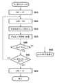
図6は記録ヘッドをキャリッジに装着したときに自動的に実行されるコンタクトチェックの処理を示すフローチャートである。この処理は、ROM203に格納された制御プログラムによりCPU201により実行される。
<Contact Check Processing (FIGS. 6-7)>
FIG. 6 is a flowchart showing a contact check process automatically executed when the recording head is mounted on the carriage. This process is executed by the
記録装置に電源が投入され、記録ヘッド11の記録装置への装着時には、まず、ステップS10ではCPU201は第1の制御信号(CNTL1)により第1のスイッチ(SW1)をオフにする。続いて、ステップS20では第2の制御信号(CNTL2)により第2のスイッチ(SW2)をオンにする。これにより、記録ヘッド11には第2電圧(V2=20V)が電力ライン42を介して印加される。
When the recording apparatus is turned on and the
そして、ステップS30では電圧が安定するまで所定の時間待ち合わせる。この待ち合わせ時間は1ミリ秒のオーダ程度の値である。 In step S30, a predetermined time is waited until the voltage stabilizes. This waiting time is a value on the order of 1 millisecond.
さらに、ステップS35では、ヘッドドライバ101から制御信号と駆動信号を記録ヘッド11に出力し、予め決められた順番でインクが吐出しない程度のエネルギーを記録素子(ヒータ)に印加して駆動し、その記録素子を加温する。
Further, in step S35, a control signal and a drive signal are output from the
図7はモニタ回路102が電力ライン42に現れる電圧(モニタ電圧:VM)を監視することで得られた電圧の時間変化を示す図である。
FIG. 7 is a diagram showing the time change of the voltage obtained by the
図7は第2のスイッチ(SW2)をオンにし、その後、モニタ電圧(VM)が安定するまで待ち合わせ、記録素子をPWM駆動するためのヒートイネーブル信号(HE)を入力した場合に得られるモニタ電圧のプロファイルを示している。このプロファイルがパルス状の変化にならないのは、回路の寄生容量が積分された結果による。なお、ここで用いるヒートイネーブル信号(HE)のパターンはコンタクトチェック処理のためにROM203にテストパターンとして格納される。
FIG. 7 shows the monitor voltage obtained when the second switch (SW2) is turned on, and then waits until the monitor voltage (VM) stabilizes, and the heat enable signal (HE) for PWM driving the recording element is input. Shows the profile. The reason why the profile does not change in a pulse shape is the result of integrating the parasitic capacitance of the circuit. The heat enable signal (HE) pattern used here is stored as a test pattern in the
このプロファイルは第2電圧(V2=20V)を印加し、駆動信号を特定の接点を介して記録ヘッドに入力することにより得ることができる。なお、別の駆動信号を別の接点を介して記録ヘッドに入力し、別の記録素子を駆動することで、同様のプロファイルを得ることができる。このようにして、次々に異なる接点を介して駆動信号を記録ヘッドに入力することで、記録ヘッドに備えられた全ての接点についてのコンタクトチェックを行うことができる。 This profile can be obtained by applying a second voltage (V2 = 20V) and inputting a drive signal to the recording head via a specific contact. A similar profile can be obtained by inputting another drive signal to the recording head via another contact and driving another recording element. In this way, by inputting a drive signal to the recording head via different contacts one after another, it is possible to perform a contact check for all the contacts provided in the recording head.
図7からの示唆されるように、1回の駆動信号の入力により、モニタ電圧のプロファイルを得るのに必要な時間は10ミリ秒程度である。上述のように、記録ヘッドには複数の(数10〜100個)の接点を有しているので、全ての接点についてのコンタクトチェックを行った場合に必要な時間は1秒程度となる。 As suggested from FIG. 7, the time required for obtaining the monitor voltage profile by inputting the drive signal once is about 10 milliseconds. As described above, since the recording head has a plurality of (several 10 to 100) contacts, the time required for contact check for all the contacts is about 1 second.
図6に戻って説明を続けると、ステップS40ではモニタ電圧(VM)を所定の閾値(VTH)と比較する。ここで、VM<VTH(閾値未満)であれば処理はステップS45に進み、VM≧VTH(閾値以上)であれば、チェック対象の接点がコンタクト不良であると判断して、処理はステップS60に進む。ステップS60では操作表示部209に設けられているLCDにコンタクト不良が発生した旨を表示し、ユーザに記録ヘッドの再装着を促す。なお、この際に操作表示部に備えられた特定のランプ(不図示)を点灯させるなどの警告処理を行っても良い。記録ヘッドの全ての接点はキャリッジの対応する接点と正しくコンタクトされているなら、ステップS60の処理は実行されない。
Returning to FIG. 6, the description will be continued. In step S40, the monitor voltage (VM) is compared with a predetermined threshold value (V TH ). Here, if VM <V TH (less than the threshold value), the process proceeds to step S45. If VM ≧ V TH (greater than the threshold value), it is determined that the contact point to be checked has a poor contact, and the process proceeds to step S45. Proceed to S60. In step S60, an indication that a contact failure has occurred is displayed on the LCD provided in the
ステップS45では、全ての接点についてのコンタクトチェックが終了したかどうかを確認する。ここで、まだ未チェックの接点があると判断された場合は、処理はステップS20に戻り、異なる接点についてのコンタクトチェックを行う。これに対して、全ての接点についてのコンタクトチェックが終了したと判断された場合には、処理はステップS50に進む。 In step S45, it is confirmed whether or not the contact check for all contacts has been completed. If it is determined that there are still unchecked contacts, the process returns to step S20 to perform contact checks for different contacts. On the other hand, if it is determined that the contact check for all the contacts has been completed, the process proceeds to step S50.
最後にステップS50では、第2の制御信号(CNTL2)により第2のスイッチ(SW2)をオフにして、コンタクトチェックの処理を終了する。 Finally, in step S50, the second switch (SW2) is turned off by the second control signal (CNTL2), and the contact check process is terminated.
<リーク検知処理(図8)>
図8はリーク検知の処理を示すフローチャートである。
<Leak detection process (FIG. 8)>
FIG. 8 is a flowchart showing a leak detection process.
この処理は記録装置の運用中に間欠的に、例えば、一定時間毎、記録媒体1ページ分の記録終了毎、或いは、所定枚数の連続記録終了毎などの所定のタイミングで実行される。なお、図6と図8とを比較すると分かるように、処理ステップ毎の個別的な処理は共通しているので、同じ処理ステップには同じステップ参照番号を付し、その説明は省略する。従って、ここでは、リーク検知処理に特有な処理についてのみ説明する。 This process is executed intermittently during operation of the recording apparatus, for example, at a predetermined timing such as every fixed time, every recording end of one page of the recording medium, or every time a predetermined number of continuous recording ends. As can be seen from a comparison between FIG. 6 and FIG. 8, the individual processing for each processing step is common, so the same processing step is given the same step reference number, and the description thereof is omitted. Therefore, only the processing unique to the leak detection processing will be described here.
リーク検知の処理ではステップS10〜S30の後、モニタ回路102で検出されるモニタ電圧(VM)を所定の閾値(VTH)と比較する。ここでは、処理を簡便化するためにコンタクトチェックで用いたのと同じ閾値を用いているが、別の値を閾値として用いても良い。ここで、VM>VTHであれば、処理はステップS50に進み、コンタクトチェックの処理と同様な処理を行うが、VM≦VTH(閾値以下)であれば、処理はステップS70に進む。
In the leak detection process, after steps S10 to S30, the monitor voltage (VM) detected by the
ステップS70では、操作表示部209に設けられているLCDに電流のリークが発生した旨を表示し、ユーザに記録ヘッドの再装着や交換を促す。なお、この際に操作表示部に備えられた特定のランプ(不図示)を点灯させるなどの警告処理を行っても良い。
In step S70, the fact that a current leak has occurred is displayed on the LCD provided in the
従って以上説明した実施例によれば、コンタクトチェック、或いは、電流リークの検知を実行する際にはかならず、大容量のコンデンサC1が回路から切り離されるので、そのコンデンサに電荷がチャージされる時間が不要となる。これにより処理の高速化が実現する。また、コンタクトチェック、或いは、電流リークの検知を実行する際には通常の電圧よりも低い電圧が用いられるので、これらの処理により記録素子を損傷することがなく安全な処理が実現する。 Therefore, according to the embodiment described above, the large-capacitance capacitor C1 is disconnected from the circuit whenever the contact check or the current leak detection is performed, so that it is not necessary to charge the capacitor. It becomes. As a result, the processing speed can be increased. In addition, since a voltage lower than a normal voltage is used when performing contact check or current leak detection, a safe process can be realized without damaging the printing element by these processes.
また、ステップS60やS70で説明したエラー処理は記録装置のみならず、記録装置を接続するホストでも実行しても良い。 Further, the error processing described in steps S60 and S70 may be executed not only by the recording apparatus but also by a host connected to the recording apparatus.
なお、以上説明した実施例ではA0やB0サイズの記録媒体に記録を行なう所謂大判の記録装置を用いたが、A4、A3、B4、B5などの比較的小さなサイズの記録媒体に記録を行なう記録装置にも本発明は適用可能である。 In the embodiment described above, a so-called large-format recording apparatus that records on an A0 or B0 size recording medium is used, but recording on a relatively small size recording medium such as A4, A3, B4, or B5 is performed. The present invention can also be applied to an apparatus.
Claims (7)
記録を行うための第1電圧を前記記録ヘッドに供給する第1の電力ラインと、
前記第1電圧より低い第2電圧を前記記録ヘッドに供給する第2の電力ラインと、
前記第1電圧の印加のオンとオフを切り替える前記第1の電力ラインに配置されたスイッチと、
前記第1電圧を供給する電圧供給源と前記スイッチとの間で前記第1の電力ラインに接続されたライン上に配置されたキャパシタと、
前記第2の電力ラインに供給される電圧をモニタするモニタ手段と、
前記第2の電力ラインに供給される電圧をモニタする場合、前記スイッチにより前記第1電圧の印加をオフにするよう制御する制御手段とを有することを特徴とする記録装置。 A recording apparatus for recording on a recording medium by the recording head while scanning a carriage equipped with a detachable recording head,
A first power line for supplying a first voltage for recording to the recording head;
A second power line for supplying a second voltage lower than the first voltage to the recording head;
A switch disposed in the first power line for switching on and off the application of the first voltage;
A capacitor disposed on a line connected to the first power line between a voltage supply source for supplying the first voltage and the switch;
Monitoring means for monitoring a voltage supplied to the second power line;
And a control unit configured to control the application of the first voltage to be turned off by the switch when the voltage supplied to the second power line is monitored.
前記記録ヘッドと前記キャリッジとの間の電気的な接続のために、前記記録ヘッドと前記キャリッジにはそれぞれ、複数の接点が設けられており、
前記記録ヘッドの前記キャリッジへの装着時には、
前記制御手段は、前記記録ヘッドに含まれる複数の記録素子の特定の記録素子を駆動するための駆動信号を前記複数の接点の1つずつの接点を介して出力し、前記複数の接点おのおののコンタクトチェックを行うことを特徴とする請求項1に記載の記録装置。 At least one of contact check between the recording head and the carriage and detection of current leak from the recording head is performed using the second voltage;
For electrical connection between the recording head and the carriage, each of the recording head and the carriage is provided with a plurality of contacts.
When mounting the recording head on the carriage,
The control means outputs a drive signal for driving a specific recording element of the plurality of recording elements included in the recording head via one of the plurality of contacts, and each of the plurality of contacts The recording apparatus according to claim 1, wherein contact check is performed.
Priority Applications (2)
| Application Number | Priority Date | Filing Date | Title |
|---|---|---|---|
| JP2012017274A JP5984402B2 (en) | 2012-01-30 | 2012-01-30 | Recording device |
| US13/712,355 US8899707B2 (en) | 2012-01-30 | 2012-12-12 | Printing apparatus |
Applications Claiming Priority (1)
| Application Number | Priority Date | Filing Date | Title |
|---|---|---|---|
| JP2012017274A JP5984402B2 (en) | 2012-01-30 | 2012-01-30 | Recording device |
Publications (3)
| Publication Number | Publication Date |
|---|---|
| JP2013154552A JP2013154552A (en) | 2013-08-15 |
| JP2013154552A5 JP2013154552A5 (en) | 2015-03-19 |
| JP5984402B2 true JP5984402B2 (en) | 2016-09-06 |
Family
ID=48869835
Family Applications (1)
| Application Number | Title | Priority Date | Filing Date |
|---|---|---|---|
| JP2012017274A Active JP5984402B2 (en) | 2012-01-30 | 2012-01-30 | Recording device |
Country Status (2)
| Country | Link |
|---|---|
| US (1) | US8899707B2 (en) |
| JP (1) | JP5984402B2 (en) |
Families Citing this family (8)
| Publication number | Priority date | Publication date | Assignee | Title |
|---|---|---|---|---|
| JP2014177081A (en) * | 2013-03-15 | 2014-09-25 | Canon Inc | Ink jet printer |
| JP6408775B2 (en) * | 2014-03-26 | 2018-10-17 | キヤノン株式会社 | Recording apparatus and detection method thereof |
| JP6574666B2 (en) * | 2015-10-02 | 2019-09-11 | キヤノン株式会社 | Recording device |
| JP6585541B2 (en) * | 2016-04-21 | 2019-10-02 | 富士フイルム株式会社 | Pattern forming apparatus, liquid ejection apparatus, and electrical failure detection method |
| JP6971903B2 (en) * | 2018-03-29 | 2021-11-24 | キヤノン株式会社 | Inspection method for recording devices and recording heads |
| JP7073218B2 (en) * | 2018-07-20 | 2022-05-23 | キヤノン株式会社 | Inkjet recording equipment, inkjet recording methods, and programs |
| JP2018192810A (en) * | 2018-09-12 | 2018-12-06 | キヤノン株式会社 | Recording device and control method therefor |
| JP2020199780A (en) * | 2020-09-23 | 2020-12-17 | 東芝テック株式会社 | Ink jet head and ink jet printer |
Family Cites Families (5)
| Publication number | Priority date | Publication date | Assignee | Title |
|---|---|---|---|---|
| KR100186592B1 (en) | 1996-06-25 | 1999-05-15 | 김광호 | Nozzle contact status confirming method of recording head in inkjet recording apparatus |
| JP3774667B2 (en) * | 2002-01-31 | 2006-05-17 | キヤノン株式会社 | Image recording device |
| JP4605055B2 (en) * | 2006-03-13 | 2011-01-05 | ソニー株式会社 | Printing device, supply power control device, and computer program |
| US7448718B2 (en) * | 2006-09-29 | 2008-11-11 | Eastman Kodak Company | Determining defective resistors in inkjet printers |
| JP2010000776A (en) * | 2008-05-19 | 2010-01-07 | Ricoh Co Ltd | Inkjet recording device |
-
2012
- 2012-01-30 JP JP2012017274A patent/JP5984402B2/en active Active
- 2012-12-12 US US13/712,355 patent/US8899707B2/en active Active
Also Published As
| Publication number | Publication date |
|---|---|
| US20130194325A1 (en) | 2013-08-01 |
| US8899707B2 (en) | 2014-12-02 |
| JP2013154552A (en) | 2013-08-15 |
Similar Documents
| Publication | Publication Date | Title |
|---|---|---|
| JP5984402B2 (en) | Recording device | |
| US10406837B2 (en) | Printing apparatus and leakage detection method of the same | |
| US9446595B2 (en) | Ink jet printing apparatus and method for controlling the same | |
| JP5614143B2 (en) | Information processing system, printing apparatus, and information processing method | |
| US8370670B2 (en) | Electronic apparatus and storage medium | |
| US7278705B2 (en) | Power management control method and printing apparatus | |
| JP6254376B2 (en) | Inkjet printer | |
| JP2009248501A (en) | Ink jet recording device | |
| US10272673B2 (en) | Printing apparatus that controls a sequence of a print unit based on a predicted electrical energy amount necessary to execute the sequence, and related control method | |
| JP2016095680A (en) | Image forming apparatus | |
| JP2008068443A (en) | Inkjet recording apparatus and recording head | |
| JP2004358963A (en) | Power management controlling method and recording apparatus | |
| JP2018012254A (en) | Recording device and fault detecting method for recording head | |
| JP2010173306A (en) | Image processing apparatus, image processing method, program, and recording medium | |
| JP5523184B2 (en) | Recording device | |
| US9294645B2 (en) | Image forming apparatus and method of operating image forming apparatus, configured to determine whether operating mode is executable based on charge remaining in battery | |
| US10906301B2 (en) | Inkjet printing apparatus | |
| JP6019713B2 (en) | Fluid ejection device, fluid ejection method and program thereof | |
| JP2018192810A (en) | Recording device and control method therefor | |
| US20230302835A1 (en) | Non-transitory computer readable medium recorded with program and liquid ejecting apparatus | |
| JP2010058458A (en) | Media printing control device in printer, printer, and media printing control method | |
| JP2006272830A (en) | Inkjet recording device | |
| JP2018144417A (en) | Ink jet recording device | |
| JP2022163788A (en) | Liquid discharge device | |
| JP2019006089A (en) | Control device, control method and program |
Legal Events
| Date | Code | Title | Description |
|---|---|---|---|
| A521 | Request for written amendment filed |
Free format text: JAPANESE INTERMEDIATE CODE: A523 Effective date: 20150129 |
|
| A621 | Written request for application examination |
Free format text: JAPANESE INTERMEDIATE CODE: A621 Effective date: 20150129 |
|
| A977 | Report on retrieval |
Free format text: JAPANESE INTERMEDIATE CODE: A971007 Effective date: 20151007 |
|
| A131 | Notification of reasons for refusal |
Free format text: JAPANESE INTERMEDIATE CODE: A131 Effective date: 20151016 |
|
| A521 | Request for written amendment filed |
Free format text: JAPANESE INTERMEDIATE CODE: A523 Effective date: 20151210 |
|
| A131 | Notification of reasons for refusal |
Free format text: JAPANESE INTERMEDIATE CODE: A131 Effective date: 20160513 |
|
| A521 | Request for written amendment filed |
Free format text: JAPANESE INTERMEDIATE CODE: A523 Effective date: 20160616 |
|
| TRDD | Decision of grant or rejection written | ||
| A01 | Written decision to grant a patent or to grant a registration (utility model) |
Free format text: JAPANESE INTERMEDIATE CODE: A01 Effective date: 20160704 |
|
| A61 | First payment of annual fees (during grant procedure) |
Free format text: JAPANESE INTERMEDIATE CODE: A61 Effective date: 20160802 |
|
| R151 | Written notification of patent or utility model registration |
Ref document number: 5984402 Country of ref document: JP Free format text: JAPANESE INTERMEDIATE CODE: R151 |