JP5975952B2 - An indoor unit for an air conditioner and a method for manufacturing the indoor unit for an air conditioner. - Google Patents
An indoor unit for an air conditioner and a method for manufacturing the indoor unit for an air conditioner. Download PDFInfo
- Publication number
- JP5975952B2 JP5975952B2 JP2013162535A JP2013162535A JP5975952B2 JP 5975952 B2 JP5975952 B2 JP 5975952B2 JP 2013162535 A JP2013162535 A JP 2013162535A JP 2013162535 A JP2013162535 A JP 2013162535A JP 5975952 B2 JP5975952 B2 JP 5975952B2
- Authority
- JP
- Japan
- Prior art keywords
- vane
- shaft
- bearing
- indoor unit
- air conditioner
- Prior art date
- Legal status (The legal status is an assumption and is not a legal conclusion. Google has not performed a legal analysis and makes no representation as to the accuracy of the status listed.)
- Active
Links
Images


Classifications
-
- F—MECHANICAL ENGINEERING; LIGHTING; HEATING; WEAPONS; BLASTING
- F24—HEATING; RANGES; VENTILATING
- F24F—AIR-CONDITIONING; AIR-HUMIDIFICATION; VENTILATION; USE OF AIR CURRENTS FOR SCREENING
- F24F1/00—Room units for air-conditioning, e.g. separate or self-contained units or units receiving primary air from a central station
-
- F—MECHANICAL ENGINEERING; LIGHTING; HEATING; WEAPONS; BLASTING
- F24—HEATING; RANGES; VENTILATING
- F24F—AIR-CONDITIONING; AIR-HUMIDIFICATION; VENTILATION; USE OF AIR CURRENTS FOR SCREENING
- F24F13/00—Details common to, or for air-conditioning, air-humidification, ventilation or use of air currents for screening
- F24F13/08—Air-flow control members, e.g. louvres, grilles, flaps or guide plates
-
- F—MECHANICAL ENGINEERING; LIGHTING; HEATING; WEAPONS; BLASTING
- F24—HEATING; RANGES; VENTILATING
- F24F—AIR-CONDITIONING; AIR-HUMIDIFICATION; VENTILATION; USE OF AIR CURRENTS FOR SCREENING
- F24F1/00—Room units for air-conditioning, e.g. separate or self-contained units or units receiving primary air from a central station
- F24F1/0007—Indoor units, e.g. fan coil units
- F24F1/0011—Indoor units, e.g. fan coil units characterised by air outlets
- F24F1/0014—Indoor units, e.g. fan coil units characterised by air outlets having two or more outlet openings
-
- F—MECHANICAL ENGINEERING; LIGHTING; HEATING; WEAPONS; BLASTING
- F24—HEATING; RANGES; VENTILATING
- F24F—AIR-CONDITIONING; AIR-HUMIDIFICATION; VENTILATION; USE OF AIR CURRENTS FOR SCREENING
- F24F1/00—Room units for air-conditioning, e.g. separate or self-contained units or units receiving primary air from a central station
- F24F1/0007—Indoor units, e.g. fan coil units
- F24F1/0043—Indoor units, e.g. fan coil units characterised by mounting arrangements
- F24F1/0047—Indoor units, e.g. fan coil units characterised by mounting arrangements mounted in the ceiling or at the ceiling
-
- F—MECHANICAL ENGINEERING; LIGHTING; HEATING; WEAPONS; BLASTING
- F24—HEATING; RANGES; VENTILATING
- F24F—AIR-CONDITIONING; AIR-HUMIDIFICATION; VENTILATION; USE OF AIR CURRENTS FOR SCREENING
- F24F13/00—Details common to, or for air-conditioning, air-humidification, ventilation or use of air currents for screening
- F24F13/08—Air-flow control members, e.g. louvres, grilles, flaps or guide plates
- F24F13/10—Air-flow control members, e.g. louvres, grilles, flaps or guide plates movable, e.g. dampers
- F24F13/14—Air-flow control members, e.g. louvres, grilles, flaps or guide plates movable, e.g. dampers built up of tilting members, e.g. louvre
- F24F13/1413—Air-flow control members, e.g. louvres, grilles, flaps or guide plates movable, e.g. dampers built up of tilting members, e.g. louvre using more than one tilting member, e.g. with several pivoting blades
-
- F—MECHANICAL ENGINEERING; LIGHTING; HEATING; WEAPONS; BLASTING
- F24—HEATING; RANGES; VENTILATING
- F24F—AIR-CONDITIONING; AIR-HUMIDIFICATION; VENTILATION; USE OF AIR CURRENTS FOR SCREENING
- F24F13/00—Details common to, or for air-conditioning, air-humidification, ventilation or use of air currents for screening
- F24F13/08—Air-flow control members, e.g. louvres, grilles, flaps or guide plates
- F24F13/10—Air-flow control members, e.g. louvres, grilles, flaps or guide plates movable, e.g. dampers
- F24F13/14—Air-flow control members, e.g. louvres, grilles, flaps or guide plates movable, e.g. dampers built up of tilting members, e.g. louvre
- F24F13/1486—Air-flow control members, e.g. louvres, grilles, flaps or guide plates movable, e.g. dampers built up of tilting members, e.g. louvre characterised by bearings, pivots or hinges
Description
本発明は、空気調和機の室内機及び空気調和機の室内機の製造方法に関する The present invention relates to an air conditioner indoor unit and a method of manufacturing an air conditioner indoor unit.
従来、軸受部を有し、吹出口が形成されている枠部材と、この枠部材に連結されたモーター収容ボックスを有する吹出口ユニットと、左右両側に回動軸を有し、枠部材に回転可能に支持された風向調整ルーバーと、モーター収容ボックス内に収容されたルーバー駆動用のステッピングモーターと、を備えた浴室暖房機があった(例えば、特許文献1参照)。特許文献1記載の浴室暖房機においては、風向調整ルーバーの回動軸がステッピングモーターの駆動軸に連結されている。
Conventionally, a frame member having a bearing portion and formed with an air outlet, an air outlet unit having a motor storage box connected to the frame member, and a rotating shaft on both the left and right sides, and rotating on the frame member There has been a bathroom heater provided with a wind direction adjusting louver supported in a possible manner and a louver driving stepping motor housed in a motor housing box (see, for example, Patent Document 1). In the bathroom heater described in
しかしながら、特許文献1記載の浴室暖房機は、風向調整ルーバー(ベーン)のステッピングモータ(モータ)から回転力を受けるベーンの回動軸が、ベーンの他方の回動軸よりも先に折れた場合、ベーンの他方の回動軸は、ベーンの落下方向への自重を支えることができず、室内空間に落下するという課題があった。
However, in the bathroom heater described in
本発明は、上述のような課題を背景としてなされたものであり、作業性を悪化させない
でベーンの落下を抑制する空気調和機の室内機及び空気調和機の室内機の製造方法を得ることを目的とする。
The present invention has been made against the background of the above-described problems, and provides an air conditioner indoor unit that suppresses vane fall without deteriorating workability and a method for manufacturing the air conditioner indoor unit. Objective.
本発明に係る空気調和機の室内機は、ベーンと、前記ベーンの両端に設けられるベーン軸と、各前記ベーン軸をそれぞれ保持するベーン軸受と、一方の前記ベーン軸に取り付けられ、前記ベーンを回転させるモータと、を備え、他方の前記ベーン軸には、ベーン軸側係合部が設けられ、他方の前記ベーン軸が挿入され、回転された状態で保持される前記ベーン軸受には、ベーン軸受側係合部が設けられ、ベーン軸側係合部とベーン軸受側係合部とは、他方の前記ベーン軸が前記ベーン軸受に挿入された状態において干渉せず、他方の前記ベーン軸が前記ベーン軸受に保持された状態において、他方の前記ベーン軸が一方の前記ベーン軸方向に基準移動量だけ移動すると、前記ベーン軸側係合部と前記ベーン軸受側係合部とが係合し、他方の前記ベーン軸の移動が規制されるものである。 The indoor unit of an air conditioner according to the present invention is attached to a vane, a vane shaft provided at both ends of the vane, a vane bearing that holds each of the vane shafts, and one of the vane shafts. A vane shaft side engagement portion provided on the other vane shaft, and the vane bearing that is held in a state where the other vane shaft is inserted and rotated is provided with a vane. A bearing side engaging portion is provided, and the vane shaft side engaging portion and the vane bearing side engaging portion do not interfere with each other when the other vane shaft is inserted into the vane bearing. When the other vane shaft moves in the vane shaft direction by a reference movement amount while being held by the vane bearing, the vane shaft side engaging portion and the vane bearing side engaging portion are engaged. Before the other In which the movement of the vane shaft is restricted.
本発明によれば、他方のベーン軸が一方のベーン軸方向に基準移動量だけ移動すると、ベーン軸側係合部とベーン軸受側係合部とが係合し、他方のベーン軸の移動が規制される。このため、例えばクレージングによって、モータからの回転力を受ける側のベーンの軸が折れても、ベーンの落下を抑制することができる。また、ベーン軸側係合部はベーン軸に設けられ、ベーン軸受側係合部はベーン軸受に設けられるため、ベーンの落下を抑制する構造が従来の構成部品のみで構成され、作業性を悪化させることもない。 According to the present invention, when the other vane shaft moves in the direction of one vane shaft by the reference movement amount, the vane shaft side engaging portion and the vane bearing side engaging portion are engaged, and the other vane shaft moves. Be regulated. For this reason, even if the axis | shaft of the vane on the side which receives the rotational force from a motor breaks by crazing, for example, the fall of a vane can be suppressed. In addition, since the vane shaft side engaging portion is provided on the vane shaft and the vane bearing side engaging portion is provided on the vane bearing, the structure for suppressing the vane dropping is configured only by the conventional components, and the workability is deteriorated. I will not let you.
以下、本発明の一実施形態に係る空気調和機を、4方向カセット形の空気調和機の室内機を例に説明する。なお、以下に示す実施の形態によって本発明が限定されるものではない。また、以下の説明において、理解を容易にするために位置を表す用語(例えば「上」、「下」など)を適宜用いるが、これは説明のためのものであって、これらの用語は本発明を限定するものではない。 Hereinafter, an air conditioner according to an embodiment of the present invention will be described by taking an indoor unit of a four-way cassette type air conditioner as an example. In addition, this invention is not limited by embodiment shown below. Further, in the following description, terms indicating positions (for example, “upper”, “lower”, etc.) are used as appropriate for easy understanding. The invention is not limited.
図1は実施の形態に係る空気調和機の室内機100の据付状態を示す斜視図である。図2は、実施の形態に係る空気調和機の室内機100を示す斜視図であり、化粧パネルコーナー蓋部8A,8Bが取り外された状態を示す。
FIG. 1 is a perspective view showing an installation state of an indoor unit 100 of an air conditioner according to an embodiment. FIG. 2 is a perspective view showing the indoor unit 100 of the air conditioner according to the embodiment, and shows a state in which the decorative panel
図1に示されるように、空気調和機の室内機100は、室内空間1に筐体2を備える。天井6からは4本の吊りボルト7が吊り下げられている。吊りボルト7の任意の位置で吊り金具5を締結することで、筐体2は天井6に取り付けられる。筐体2は、例えば、その外郭における4箇所で吊りボルト7に取り付けられる。
As shown in FIG. 1, an indoor unit 100 of an air conditioner includes a
筐体2は、室内送風機(図示省略)と、室内空気を熱交換する室内機熱交換器(図示省略)と、を収容している。筐体2の下面には、吸入グリル3a及び吹出口3bが設けられている。吸入グリル3aは、筐体2の下面の中央に設けられている。吹出口3bは、吸入グリル3aの周囲に設けられている。吹出口3bには、例えば平板形状のベーン4が設けられている。ベーン4は、室内機100の内部から吹出口3bを通って室内側に向かう風量を調整し風向を案内する。
The housing |
筐体2の下面には、化粧パネル3が取り付けられている。化粧パネル3は、着脱自在な化粧パネルコーナー蓋部8A,8Bを有する。図1に示される状態で、化粧パネルコーナー蓋部8A,8Bを取り外すと、図2のように各種部品が露出する。各種部品の詳細については後述する。なお、化粧パネルコーナー蓋部8Aを取り外した部分が図2の点線枠Aで囲まれる部分である。また、化粧パネルコーナー蓋部8Bを取り外した部分が図2の点線枠Bで囲まれる部分である。
A
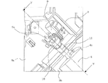
図3は実施の形態に係る空気調和機の室内機100の化粧パネルコーナー蓋部8A,8Bを取り外した状態のベーン4近傍の拡大図である。ここで、図2の点線枠Aで囲まれる部分を拡大すると、図3の点線枠Aで囲まれる部分となる。また、図2の点線枠Bで囲まれる部分を拡大すると、図3の点線枠Bで囲まれる部分となる。図3に示されるように、ベーン4は、ベーン軸4a及びベーン軸4bを有する。
FIG. 3 is an enlarged view of the vicinity of the
ベーン軸4aはベーン4の一端に設けられる。ベーン軸4aの近傍には、化粧パネルコーナー部8a、モータ9、ベーンギア10、及びベーン軸受11が設けられる。化粧パネルコーナー部8a、モータ9、ベーンギア10、及びベーン軸受11は、化粧パネルコーナー蓋部8Aを取り外すことで露出する部材である。化粧パネルコーナー部8aは、ベーン軸受11が挿入されるように一部が開口した壁面である。ベーン軸受11はベーン軸4aを差し込むための部材である。
The
ベーン軸4bはベーン4の他端に設けられる。ベーン軸4bの近傍には、化粧パネルコーナー部8b及びベーン軸受12が設けられる。化粧パネルコーナー部8b及びベーン軸受12は、化粧パネルコーナー蓋部8Bを取り外すことで露出する部材である。化粧パネルコーナー部8bは、ベーン軸受12が挿入されるように一部が開口した壁面である。ベーン軸受12はベーン軸4bを差し込むための部材である。
The
図4は実施の形態に係る空気調和機の室内機100のベーン軸4a近傍を示す斜視図である。図5は図4のY−Y断面図である。
FIG. 4 is a perspective view showing the vicinity of the
図4に示されるように、モータ9は、ベーン4を回転させるための部材である。モータ9の回転力はベーン軸4aに伝えられる。モータ9が回転することで、ベーン4はベーン軸4aを中心として回転する。モータ9には、モータ9を保持するモータ保持板金9aが取り付けられる。
As shown in FIG. 4, the
図5に示されるように、ベーンギア10は、凸状のベーンギア軸10aと、凹部10bとを有する部材である。ベーンギア軸10aは、モータ保持板金9aに形成される穴部9a1に挿入される部材である。凹部10bは、ベーン軸4aの先端が圧入嵌合される部位である。ベーン軸受11は、爪部11a及び鍔11bを有する。
As shown in FIG. 5, the
爪部11aは、ベーン軸受11を化粧パネル3に保持するための部材であり、化粧パネルコーナー部8a側に向かうように突出している。鍔11bは、ベーンギア10側に向かうように突出している。モータ保持板金9aとベーンギア10との間には隙間13aが形成されている。ベーンギア10とベーン軸受11との間には隙間13bが形成されている。
The
以下に、空気調和機の室内機100のベーン軸4a側に位置する部材の組立手順について説明する。
まず、ベーン軸4aをベーン軸受11に挿入し、ベーン軸4aの先端をベーンギア10の凹部10bに圧入嵌合する。次に、ベーンギア軸10aを穴部9a1に差し込む。このように、ベーン軸4aをベーンギア10の凹部10bの底部まで挿入することで、ベーン4の組立後の位置が決定される。ベーン4の組立後におけるベーン4の軸方向移動量は、隙間13a及び隙間13bに応じて決定される。
Below, the assembly procedure of the member located in the vane axis |
First, the
図6は実施の形態に係る空気調和機の室内機100の組立時のベーン軸4b近傍を示す斜視図である。図7は図6のZ−Z断面図である。図8は実施の形態に係る空気調和機の室内機100の製品出荷時のベーン軸4b近傍を示す断面図である。図9は実施の形態に係る空気調和機の室内機100のベーン軸4b近傍を示す断面図であり、ベーン4落下時の状態を示す。
FIG. 6 is a perspective view showing the vicinity of the
図6に示されるように、ベーン軸4bは、例えば扇形のリブ4cを有する。リブ4cは、組立時において、例えば上方に突出するように設けられる。ベーン軸受12は、爪部12a、鍔12b、及び爪部12cを有する。爪部12aは、化粧パネルコーナー部8b側に向かうように突出している。鍔12bは、化粧パネルコーナー部8bとは反対側に向かうように突出している。鍔12bは自重方向にたわむように構成されている。鍔12bがこのように構成されているため、ベーン軸受12を化粧パネル3から容易に取り外すことができ、メンテナンスを容易に行うことができる。爪部12cは、例えば、上方に突出するように設けられる。
As shown in FIG. 6, the
図7に示されるように、ベーン軸4bは、例えばリブ4cが上方に突出した状態で、ベーン軸受12に挿入される。このため、扇形のリブ4cは爪部12cを避けることができ、干渉することなくベーン軸4bを挿入することができる。
As shown in FIG. 7, the
以下に、空気調和機の室内機100のベーン軸4b側に位置する部材の組立手順について説明する。
まず、ベーン軸4bをベーン軸受12に挿入する。次に、ベーン軸受12を化粧パネルコーナー部8bに挿入する。このようにして、ベーン4は化粧パネルコーナー部8bに保持される。すなわち、ベーン4は化粧パネル3に保持される。爪部12aが化粧パネルコーナー部8bに引っ掛かることで、ベーン軸受12は化粧パネル3に保持される。製品出荷状態時には、ベーン軸4bを180°回転することで、図8のように、ベーン軸4bが位置する。
Below, the assembly procedure of the member located in the vane axis |
First, the
図8に示されるように、製品出荷状態時においては、リブ4cは、その先端が自重方向に向けられ、リブ4c及び爪部12cは軸方向で重なり合うように配置される。このとき、爪部12cはリブ4cよりもベーン軸4a側に位置し、リブ4cと爪部12cとの間には隙間13cが形成されている。
As shown in FIG. 8, at the time of product shipment, the
隙間13cは、隙間13aよりも大きくなるように設計されている。このため、通常運転時に、隙間13aが無くなるようにベーン4が移動しても、隙間13cが無くなることはなく、リブ4cと爪部12cとが干渉することはない。したがって、ベーン軸4bとベーン軸受12の摺動性及びベーン4の駆動安定性を損なうことはない。
The
以下に、空気調和機の室内機100のベーン軸4aが折れた場合の動作について説明する。
まず、モータ9の回転力を受ける側のベーン軸4a(図5)が折れると、ベーン4は、図9の紙面左方向に移動し、自重で室内空間1に落下しようとする。そして、ベーン4が所定量(基準移動量)だけ移動した状態で、リブ4cと爪部12cとが係合し、ベーン軸4aの移動は規制される。したがって、ベーン4の落下が規制されることとなる。
Below, operation | movement when the
First, when the
なお、リブ4cの扇形状を大きくすると、室内機100の運転中にベーン軸4aが折れたとき、リブ4cと爪部12cとが係合しやすくなる。ただし、リブ4cの扇形状が過度に大きいと、リブ4cが、ベーン軸4bのベーン軸受12への挿入を妨げることとなる。このため、リブ4cを、その扇形状が過度に大きくならないように設計することが望ましい。
When the fan shape of the
以上のように、本実施の形態に係る空気調和機の室内機100は、ベーン4と、ベーン4の両端に設けられるベーン軸4a,4bと、ベーン軸4a,4bをそれぞれ保持するベーン軸受11,12と、ベーン軸4aに取り付けられ、ベーン4を回転させるモータ9と、を備え、ベーン軸4aには、リブ4cが設けられ、ベーン軸4bを保持するベーン軸受12には、爪部12cが設けられ、ベーン軸4bがベーン軸4a方向に基準移動量だけ移動すると、リブ4cと爪部12cとが係合し、ベーン軸4bの移動が規制される。
このため、クレージングなどによりモータ9からの回転力を受ける側のベーン軸4aが折れても、ベーン4の落下を抑制することができる。また、リブ4cはベーン軸4bに設けられ、爪部12cはベーン軸受12に設けられるため、ベーン4の落下を抑制する構造が従来の構成部品のみで構成され、作業性を悪化させることもない。したがって、組み付け、取り外しを容易に行う空気調和機の室内機100を得ることができる。
As described above, the air conditioner indoor unit 100 according to the present embodiment includes the
For this reason, even if the
なお、リブ4cが、本発明のベーン軸側係合部に相当する。
また、爪部12cが、本発明のベーン軸受側係合部に相当する。
The
Further, the
1 室内空間、2 筐体、3 化粧パネル、3a 吸入グリル、3b 吹出口、4 ベーン、4a ベーン軸、4b ベーン軸、4c リブ、5 吊り金具、6 天井、7 吊りボルト、8A 化粧パネルコーナー蓋部、8B 化粧パネルコーナー蓋部、8a 化粧パネルコーナー部、8b 化粧パネルコーナー部、9 モータ、9a モータ保持板金、9a1 穴部、10 ベーンギア、10a ベーンギア軸、10b 凹部、11 ベーン軸受、11a 爪部、11b 鍔、12 ベーン軸受、12a 爪部、12b 鍔、12c 爪部、13a 隙間、13b 隙間、13c 隙間、100 室内機。
DESCRIPTION OF
Claims (4)
前記ベーンの両端に設けられるベーン軸と、
各前記ベーン軸をそれぞれ保持するベーン軸受と、
一方の前記ベーン軸に取り付けられ、前記ベーンを回転させるモータと、を備え、
他方の前記ベーン軸には、ベーン軸側係合部が設けられ、
他方の前記ベーン軸が挿入され、回転された状態で保持される前記ベーン軸受には、ベーン軸受側係合部が設けられ、
ベーン軸側係合部とベーン軸受側係合部とは、
他方の前記ベーン軸が前記ベーン軸受に挿入された状態において干渉せず、
他方の前記ベーン軸が前記ベーン軸受に保持された状態において、他方の前記ベーン軸が一方の前記ベーン軸方向に基準移動量だけ移動すると、前記ベーン軸側係合部と前記ベーン軸受側係合部とが係合し、他方の前記ベーン軸の移動が規制される
ことを特徴とする空気調和機の室内機。 Vane,
A vane shaft provided at both ends of the vane;
A vane bearing for holding each of the vane shafts;
A motor attached to one of the vane shafts and rotating the vane,
The other vane shaft is provided with a vane shaft side engaging portion,
The vane bearing that is held in a state where the other vane shaft is inserted and rotated is provided with a vane bearing side engaging portion,
The vane shaft side engaging portion and the vane bearing side engaging portion are
The other vane shaft does not interfere in the state inserted in the vane bearing,
In a state where the other vane shaft is held by the vane bearing, when the other vane shaft moves by a reference movement amount in the one vane shaft direction, the vane shaft side engagement portion and the vane bearing side engagement An indoor unit of an air conditioner, wherein the other unit is engaged and the movement of the other vane shaft is restricted.
前記ベーン軸受側係合部は、前記ベーン軸側係合部よりも一方の前記ベーン軸側に位置する
ことを特徴とする請求項1に記載の空気調和機の室内機。 In a state where each vane shaft is held by each vane bearing,
The indoor unit of an air conditioner according to claim 1, wherein the vane bearing side engagement portion is positioned closer to the vane shaft than the vane shaft side engagement portion.
ことを特徴とする請求項1又は請求項2に記載の空気調和機の室内機。 The indoor unit of an air conditioner according to claim 1 or 2, wherein the vane shaft side engaging portion is a fan-shaped rib.
前記ベーンの両端に設けられるベーン軸と、 A vane shaft provided at both ends of the vane;
各前記ベーン軸をそれぞれ保持するベーン軸受と、 A vane bearing for holding each of the vane shafts;
一方の前記ベーン軸に取り付けられ、前記ベーンを回転させるモータと、を備え、 A motor attached to one of the vane shafts and rotating the vane,
他方の前記ベーン軸には、ベーン軸側係合部が設けられ、 The other vane shaft is provided with a vane shaft side engaging portion,
他方の前記ベーン軸を保持する前記ベーン軸受には、ベーン軸受側係合部が設けられ、 The vane bearing that holds the other vane shaft is provided with a vane bearing side engaging portion,
他方の前記ベーン軸は、前記ベーン軸側係合部と前記ベーン軸受側係合部とを干渉させずに前記ベーン軸受に挿入され、 The other vane shaft is inserted into the vane bearing without causing interference between the vane shaft side engaging portion and the vane bearing side engaging portion,
他方の前記ベーン軸が、前記ベーン軸受に挿入された状態で回転されて前記ベーン軸受に保持され、 The other vane shaft is rotated while being inserted into the vane bearing and is held by the vane bearing,
他方の前記ベーン軸が一方の前記ベーン軸方向に基準移動量だけ移動すると、前記ベーン軸側係合部と前記ベーン軸受側係合部とが係合し、他方の前記ベーン軸の移動が規制される When the other vane shaft moves in the direction of the one vane shaft by a reference movement amount, the vane shaft side engaging portion and the vane bearing side engaging portion are engaged, and the movement of the other vane shaft is restricted. Be done
ことを特徴とする空気調和機の室内機の製造方法。 A method of manufacturing an indoor unit of an air conditioner characterized by the above.
Priority Applications (6)
| Application Number | Priority Date | Filing Date | Title |
|---|---|---|---|
| JP2013162535A JP5975952B2 (en) | 2013-08-05 | 2013-08-05 | An indoor unit for an air conditioner and a method for manufacturing the indoor unit for an air conditioner. |
| US14/447,802 US9958181B2 (en) | 2013-08-05 | 2014-07-31 | Indoor unit for air-conditioning apparatus |
| EP14179214.3A EP2835588B1 (en) | 2013-08-05 | 2014-07-31 | Indoor unit for air-conditioning apparatus |
| TR2018/08734T TR201808734T4 (en) | 2013-08-05 | 2014-07-31 | Indoor unit for air conditioning apparatus. |
| CN201410377522.3A CN104344460B (en) | 2013-08-05 | 2014-08-01 | Indoor unit for air-conditioning apparatus |
| CN201420433241.0U CN204026848U (en) | 2013-08-05 | 2014-08-01 | The indoor set of air conditioner |
Applications Claiming Priority (1)
| Application Number | Priority Date | Filing Date | Title |
|---|---|---|---|
| JP2013162535A JP5975952B2 (en) | 2013-08-05 | 2013-08-05 | An indoor unit for an air conditioner and a method for manufacturing the indoor unit for an air conditioner. |
Publications (2)
| Publication Number | Publication Date |
|---|---|
| JP2015031474A JP2015031474A (en) | 2015-02-16 |
| JP5975952B2 true JP5975952B2 (en) | 2016-08-23 |
Family
ID=51266109
Family Applications (1)
| Application Number | Title | Priority Date | Filing Date |
|---|---|---|---|
| JP2013162535A Active JP5975952B2 (en) | 2013-08-05 | 2013-08-05 | An indoor unit for an air conditioner and a method for manufacturing the indoor unit for an air conditioner. |
Country Status (5)
| Country | Link |
|---|---|
| US (1) | US9958181B2 (en) |
| EP (1) | EP2835588B1 (en) |
| JP (1) | JP5975952B2 (en) |
| CN (2) | CN104344460B (en) |
| TR (1) | TR201808734T4 (en) |
Families Citing this family (15)
| Publication number | Priority date | Publication date | Assignee | Title |
|---|---|---|---|---|
| JP5975952B2 (en) * | 2013-08-05 | 2016-08-23 | 三菱電機株式会社 | An indoor unit for an air conditioner and a method for manufacturing the indoor unit for an air conditioner. |
| JP5972252B2 (en) * | 2013-12-20 | 2016-08-17 | 三菱電機株式会社 | Indoor unit and air conditioner |
| JP1541102S (en) * | 2014-06-06 | 2017-12-18 | ||
| JP1523384S (en) * | 2014-07-14 | 2015-05-18 | ||
| USD759222S1 (en) * | 2014-09-23 | 2016-06-14 | Daikin Industries Ltd. | Air conditioner |
| USD759223S1 (en) * | 2014-09-23 | 2016-06-14 | Daikin Industries Ltd. | Air conditioner |
| JP1536295S (en) * | 2015-01-29 | 2015-10-26 | ||
| JP1535863S (en) * | 2015-01-29 | 2015-10-26 | ||
| JP1536294S (en) * | 2015-01-29 | 2015-10-26 | ||
| JP1536293S (en) * | 2015-01-29 | 2015-10-26 | ||
| JP1535861S (en) * | 2015-01-29 | 2015-10-26 | ||
| JP1535862S (en) * | 2015-01-29 | 2015-10-26 | ||
| CN110291340B (en) * | 2017-02-21 | 2021-05-18 | 夏普株式会社 | Air conditioner |
| WO2019162993A1 (en) * | 2018-02-20 | 2019-08-29 | 三菱電機株式会社 | Indoor unit for air conditioner and air conditioner comprising same indoor unit |
| US20220090818A1 (en) * | 2019-03-14 | 2022-03-24 | Mitsubishi Electric Corporation | Indoor unit of air-conditioning apparatus and air-conditioning apparatus |
Family Cites Families (16)
| Publication number | Priority date | Publication date | Assignee | Title |
|---|---|---|---|---|
| US2972358A (en) * | 1956-05-15 | 1961-02-21 | Hinden Milton | Vane runner fitting for ducts and the like |
| US3045580A (en) * | 1959-08-04 | 1962-07-24 | Practical Tool & Engineering C | Adjustable register for air flow |
| US3996845A (en) * | 1975-07-16 | 1976-12-14 | Anemostat Products Division, Dynamics Corporation Of America | Air handling grille and method of making the same |
| JPH0327233Y2 (en) * | 1986-02-06 | 1991-06-12 | ||
| JPS6318307U (en) * | 1986-07-22 | 1988-02-06 | ||
| JPH0684246U (en) * | 1993-05-21 | 1994-12-02 | 協立エアテック株式会社 | A device to prevent the falling of the linear outlet blades |
| US5443420A (en) * | 1993-06-18 | 1995-08-22 | Samsung Electronics Co., Ltd. | Air flow direction control apparatus and the method thereof |
| JPH1194344A (en) * | 1997-09-19 | 1999-04-09 | Fujitsu General Ltd | Air conditioner |
| JP3468230B2 (en) | 2001-06-27 | 2003-11-17 | 株式会社ノーリツ | Bathroom heater |
| CN1724789A (en) * | 2004-07-21 | 2006-01-25 | 乐金电子(天津)电器有限公司 | Electric machine installing structure of drying machine fan blower |
| JP4356606B2 (en) | 2004-12-22 | 2009-11-04 | 三菱電機株式会社 | Air conditioner wind direction adjustment device |
| JP4739886B2 (en) * | 2005-09-27 | 2011-08-03 | 三洋電機株式会社 | Air conditioner |
| JP2009198133A (en) * | 2008-02-25 | 2009-09-03 | Sharp Corp | Air conditioner |
| JP2012193933A (en) | 2011-03-18 | 2012-10-11 | Panasonic Corp | Apparatus for ventilating and air-conditioning bathroom |
| CN103765119B (en) * | 2011-10-14 | 2016-08-17 | 松下电器产业株式会社 | Air conditioner and the indoor set of air conditioner |
| JP5975952B2 (en) | 2013-08-05 | 2016-08-23 | 三菱電機株式会社 | An indoor unit for an air conditioner and a method for manufacturing the indoor unit for an air conditioner. |
-
2013
- 2013-08-05 JP JP2013162535A patent/JP5975952B2/en active Active
-
2014
- 2014-07-31 TR TR2018/08734T patent/TR201808734T4/en unknown
- 2014-07-31 US US14/447,802 patent/US9958181B2/en active Active
- 2014-07-31 EP EP14179214.3A patent/EP2835588B1/en active Active
- 2014-08-01 CN CN201410377522.3A patent/CN104344460B/en active Active
- 2014-08-01 CN CN201420433241.0U patent/CN204026848U/en active Active
Also Published As
| Publication number | Publication date |
|---|---|
| EP2835588A2 (en) | 2015-02-11 |
| CN204026848U (en) | 2014-12-17 |
| US20150038068A1 (en) | 2015-02-05 |
| US9958181B2 (en) | 2018-05-01 |
| EP2835588B1 (en) | 2018-05-23 |
| CN104344460A (en) | 2015-02-11 |
| CN104344460B (en) | 2017-04-12 |
| TR201808734T4 (en) | 2018-07-23 |
| JP2015031474A (en) | 2015-02-16 |
| EP2835588A3 (en) | 2015-03-04 |
Similar Documents
| Publication | Publication Date | Title |
|---|---|---|
| JP5975952B2 (en) | An indoor unit for an air conditioner and a method for manufacturing the indoor unit for an air conditioner. | |
| JP6157407B2 (en) | Air conditioner wind direction adjusting device and air conditioner | |
| JP2006292312A (en) | Top plate structure of high place-installation type air conditioner | |
| JP4598043B2 (en) | Ceiling type air conditioner | |
| EP3091304A1 (en) | Air conditioner | |
| JP2010121859A (en) | Outdoor unit for air conditioner | |
| JP4946320B2 (en) | Air conditioning indoor unit | |
| JP4704226B2 (en) | Ceiling cassette type air conditioner | |
| JP5745480B2 (en) | Air conditioner | |
| JP4739886B2 (en) | Air conditioner | |
| JP2019135432A (en) | Louver, air conditioner, and assembly method of air conditioner | |
| JP2008190809A (en) | Air conditioner | |
| JP4943833B2 (en) | Air conditioner | |
| JP2010032132A (en) | Air conditioner | |
| JP5963507B2 (en) | Air conditioner | |
| JP2006003011A (en) | Top plate structure of high altitude installation type air conditioner | |
| JP5343892B2 (en) | Duct type air conditioner | |
| JP2010121858A (en) | Outdoor unit for air conditioner | |
| JP2008106951A (en) | Air conditioner | |
| JP2011052931A (en) | Variable air volume unit | |
| JP2008070051A (en) | Airflow direction changing device and air conditioner comprising the same | |
| WO2014156563A1 (en) | Air conditioner | |
| JP2016205666A (en) | Air conditioner | |
| JP5315949B2 (en) | Air conditioner | |
| JP2017141968A (en) | Air conditioner |
Legal Events
| Date | Code | Title | Description |
|---|---|---|---|
| A621 | Written request for application examination |
Free format text: JAPANESE INTERMEDIATE CODE: A621 Effective date: 20150703 |
|
| A977 | Report on retrieval |
Free format text: JAPANESE INTERMEDIATE CODE: A971007 Effective date: 20151124 |
|
| A131 | Notification of reasons for refusal |
Free format text: JAPANESE INTERMEDIATE CODE: A131 Effective date: 20151208 |
|
| A521 | Request for written amendment filed |
Free format text: JAPANESE INTERMEDIATE CODE: A523 Effective date: 20160128 |
|
| TRDD | Decision of grant or rejection written | ||
| A01 | Written decision to grant a patent or to grant a registration (utility model) |
Free format text: JAPANESE INTERMEDIATE CODE: A01 Effective date: 20160621 |
|
| A61 | First payment of annual fees (during grant procedure) |
Free format text: JAPANESE INTERMEDIATE CODE: A61 Effective date: 20160719 |
|
| R150 | Certificate of patent or registration of utility model |
Ref document number: 5975952 Country of ref document: JP Free format text: JAPANESE INTERMEDIATE CODE: R150 |
|
| R250 | Receipt of annual fees |
Free format text: JAPANESE INTERMEDIATE CODE: R250 |
|
| R250 | Receipt of annual fees |
Free format text: JAPANESE INTERMEDIATE CODE: R250 |
|
| R250 | Receipt of annual fees |
Free format text: JAPANESE INTERMEDIATE CODE: R250 |
|
| R250 | Receipt of annual fees |
Free format text: JAPANESE INTERMEDIATE CODE: R250 |
|
| R250 | Receipt of annual fees |
Free format text: JAPANESE INTERMEDIATE CODE: R250 |