JP5969901B2 - Print head with particle circulation with separation - Google Patents
Print head with particle circulation with separation Download PDFInfo
- Publication number
- JP5969901B2 JP5969901B2 JP2012253526A JP2012253526A JP5969901B2 JP 5969901 B2 JP5969901 B2 JP 5969901B2 JP 2012253526 A JP2012253526 A JP 2012253526A JP 2012253526 A JP2012253526 A JP 2012253526A JP 5969901 B2 JP5969901 B2 JP 5969901B2
- Authority
- JP
- Japan
- Prior art keywords
- phase change
- ink
- change ink
- flow
- divider
- Prior art date
- Legal status (The legal status is an assumption and is not a legal conclusion. Google has not performed a legal analysis and makes no representation as to the accuracy of the status listed.)
- Expired - Fee Related
Links
Images


Classifications
-
- B—PERFORMING OPERATIONS; TRANSPORTING
- B41—PRINTING; LINING MACHINES; TYPEWRITERS; STAMPS
- B41J—TYPEWRITERS; SELECTIVE PRINTING MECHANISMS, i.e. MECHANISMS PRINTING OTHERWISE THAN FROM A FORME; CORRECTION OF TYPOGRAPHICAL ERRORS
- B41J2/00—Typewriters or selective printing mechanisms characterised by the printing or marking process for which they are designed
- B41J2/005—Typewriters or selective printing mechanisms characterised by the printing or marking process for which they are designed characterised by bringing liquid or particles selectively into contact with a printing material
- B41J2/01—Ink jet
- B41J2/17—Ink jet characterised by ink handling
- B41J2/175—Ink supply systems ; Circuit parts therefor
-
- B—PERFORMING OPERATIONS; TRANSPORTING
- B41—PRINTING; LINING MACHINES; TYPEWRITERS; STAMPS
- B41J—TYPEWRITERS; SELECTIVE PRINTING MECHANISMS, i.e. MECHANISMS PRINTING OTHERWISE THAN FROM A FORME; CORRECTION OF TYPOGRAPHICAL ERRORS
- B41J2/00—Typewriters or selective printing mechanisms characterised by the printing or marking process for which they are designed
- B41J2/005—Typewriters or selective printing mechanisms characterised by the printing or marking process for which they are designed characterised by bringing liquid or particles selectively into contact with a printing material
- B41J2/01—Ink jet
- B41J2/015—Ink jet characterised by the jet generation process
- B41J2/04—Ink jet characterised by the jet generation process generating single droplets or particles on demand
- B41J2/045—Ink jet characterised by the jet generation process generating single droplets or particles on demand by pressure, e.g. electromechanical transducers
-
- B—PERFORMING OPERATIONS; TRANSPORTING
- B41—PRINTING; LINING MACHINES; TYPEWRITERS; STAMPS
- B41J—TYPEWRITERS; SELECTIVE PRINTING MECHANISMS, i.e. MECHANISMS PRINTING OTHERWISE THAN FROM A FORME; CORRECTION OF TYPOGRAPHICAL ERRORS
- B41J2/00—Typewriters or selective printing mechanisms characterised by the printing or marking process for which they are designed
- B41J2/005—Typewriters or selective printing mechanisms characterised by the printing or marking process for which they are designed characterised by bringing liquid or particles selectively into contact with a printing material
- B41J2/01—Ink jet
- B41J2/135—Nozzles
- B41J2/14—Structure thereof only for on-demand ink jet heads
- B41J2/14016—Structure of bubble jet print heads
- B41J2/14145—Structure of the manifold
-
- B—PERFORMING OPERATIONS; TRANSPORTING
- B41—PRINTING; LINING MACHINES; TYPEWRITERS; STAMPS
- B41J—TYPEWRITERS; SELECTIVE PRINTING MECHANISMS, i.e. MECHANISMS PRINTING OTHERWISE THAN FROM A FORME; CORRECTION OF TYPOGRAPHICAL ERRORS
- B41J2/00—Typewriters or selective printing mechanisms characterised by the printing or marking process for which they are designed
- B41J2/005—Typewriters or selective printing mechanisms characterised by the printing or marking process for which they are designed characterised by bringing liquid or particles selectively into contact with a printing material
- B41J2/01—Ink jet
- B41J2/17—Ink jet characterised by ink handling
- B41J2/175—Ink supply systems ; Circuit parts therefor
- B41J2/17593—Supplying ink in a solid state
-
- B—PERFORMING OPERATIONS; TRANSPORTING
- B41—PRINTING; LINING MACHINES; TYPEWRITERS; STAMPS
- B41J—TYPEWRITERS; SELECTIVE PRINTING MECHANISMS, i.e. MECHANISMS PRINTING OTHERWISE THAN FROM A FORME; CORRECTION OF TYPOGRAPHICAL ERRORS
- B41J2/00—Typewriters or selective printing mechanisms characterised by the printing or marking process for which they are designed
- B41J2/005—Typewriters or selective printing mechanisms characterised by the printing or marking process for which they are designed characterised by bringing liquid or particles selectively into contact with a printing material
- B41J2/01—Ink jet
- B41J2/135—Nozzles
- B41J2/14—Structure thereof only for on-demand ink jet heads
- B41J2002/14419—Manifold
Description
本明細書は、一般的に、1つ以上の印字ヘッドを有するインクジェットプリンタに関し、さらに詳細には、インクジェットプリンタ内のインク容器に関する。 This specification relates generally to ink jet printers having one or more print heads, and more particularly to ink containers within an ink jet printer.
インクジェットプリンタは受像部材上に液体インクを射出する複数のインクジェットを作動させる印字ヘッドを有している。プリンタ内に設置されたカートリッジの中にある容器内に液体インクを貯蔵してもよい。このようなインクは、水性インクまたはインクエマルジョンであってもよい。他のインクジェットプリンタは固形のインクを受け取り、その後、受像部材上に射出するために固体インクを溶かして液体インクを生成する。これらの固体インクプリンタでは、固体インクは、ペレット状、インクスティック状、顆粒状、トローチ状、または他の形状で提供できる。固体インクはインク装填機内に通常セットされており、供給シュートまたは供給経路を通ってインクを溶かす溶融装置に送出される。その後、溶けたインクは容器内に集められて、導管またはその種の他のものの中を通って1つ以上の印字ヘッドに供給される。他のインクジェットプリンタでは、インクはゲル状で供給できる。また、ゲルを所定温度まで加熱してインクの粘度を変えることにより、インクは印字ヘッドで射出するのに適したものになる。 The ink jet printer has a print head for operating a plurality of ink jets that eject liquid ink onto an image receiving member. Liquid ink may be stored in a container in a cartridge installed in the printer. Such an ink may be an aqueous ink or an ink emulsion. Other inkjet printers receive solid ink and then melt the solid ink to produce liquid ink for ejection onto the image receiving member. In these solid ink printers, the solid ink can be provided in pellets, ink sticks, granules, troches, or other shapes. Solid ink is usually set in an ink loader and is sent through a supply chute or supply path to a melting device that melts the ink. The melted ink is then collected in a container and fed into one or more printheads through a conduit or the like. In other inkjet printers, the ink can be supplied in gel form. Further, by changing the viscosity of the ink by heating the gel to a predetermined temperature, the ink becomes suitable for being ejected by the print head.
典型的なインクジェットプリンタが、1つ以上の印字ヘッドを使用している。各印字ヘッドは、オープンギャップを横切って受像部材にインク滴を射出して画像を形成するための個々のノズルの配列を通常含んでいる。受像部材は記録媒体の連続ウェブ、ひと続きの媒体シートであってもよく、または受像部材は印字ドラムまたはエンドレスベルトのような回転表面であってもよい。回転表面上に印刷された画像は、回転表面およびトランスフィックスローラにより形成されるトランスフィックスニップ内の機械力により記録媒体に後で転写される。 A typical ink jet printer uses one or more printheads. Each printhead typically includes an array of individual nozzles for ejecting ink droplets onto the image receiving member across the open gap to form an image. The image receiving member may be a continuous web of recording media, a series of media sheets, or the image receiving member may be a rotating surface such as a printing drum or endless belt. The image printed on the rotating surface is later transferred to a recording medium by mechanical force in a transfix nip formed by the rotating surface and a transfix roller.
インクジェット印字ヘッドでは、印字ヘッドの外部にあるインク容器内に、および印字ヘッドの中に組み込まれたインク容器内にインクを貯蔵している。ほこりまたはごみの粒子が、容器および/または印字ヘッドの製造中に容器に入ることがある。これらの粒子は容器の中の液体インクの流れにより自由になって、液体インク中に浮遊するようになる可能性がある。これらの粒子が印字ヘッドのインクジェットスタックに入ると、これらの粒子は1つ以上のインクジェットへのインクの流れを妨げる可能性がある。その結果として、いくつかのインクジェットが間欠的になる可能性があり、インクジェットがときどきは発射するが、普段は発射しない可能性があることを意味している。インクが印字ヘッドのインクジェットスタックに到達する前に液体インク中の粒子の存在を低減することは、インクジェットプリンタにおいて依然として望ましい目標である。 In an ink jet print head, ink is stored in an ink container outside the print head and in an ink container built into the print head. Dust or dust particles may enter the container during the manufacture of the container and / or printhead. These particles may become free by the flow of liquid ink in the container and become suspended in the liquid ink. As these particles enter the inkjet stack of the print head, these particles can interfere with the flow of ink to one or more inkjets. As a result, some ink jets can be intermittent, meaning that ink jets sometimes fire, but usually do not. Reducing the presence of particles in liquid ink before the ink reaches the inkjet stack of the printhead is still a desirable goal in inkjet printers.
液体インク中の粒子の存在を低減する容器を有する印字ヘッドが開発されてきた。画像装置で用いる印字ヘッドは、溶けた相転移インクを受像部材上に付着させる。印字ヘッドは、溶けた相転移インクを貯蔵する空間を取り囲むために、少なくとも1つの側壁と、その少なくとも1つの側壁に連結された底壁と、を含んでいる。少なくとも1つの側壁と、底壁と、のうちの一方は、容器の外部の溶けた相転移インクの流れを提供するための出口を含んでいる。循環装置が、溶けた相転移インクの流れを空間の中に生成して、流速がより遅くなって粒子状物質が流れから外れる位置に粒子状物質を移動させるように構成されている。出口に連結された複数のインク滴発生装置が、溶けた相転移インクの滴を受像部材上に放出する。 Printheads having containers that reduce the presence of particles in liquid ink have been developed. The print head used in the image apparatus deposits the melted phase change ink on the image receiving member. The print head includes at least one side wall and a bottom wall connected to the at least one side wall to enclose a space for storing the melted phase change ink. One of the at least one sidewall and the bottom wall includes an outlet for providing a flow of molten phase change ink outside the container. A circulation device is configured to generate a flow of melted phase change ink in the space to move the particulate material to a position where the flow rate is slower and the particulate material is out of the flow. A plurality of ink drop generators connected to the outlet ejects melted phase change ink drops onto the image receiving member.
他の実施形態では、相転移インク容器を構成しており、この相転移インク容器は、それが印字ヘッドに供給する溶けた相転移インク内の粒子の存在を低減するのを助ける。溶けた相転移インクを印字ヘッドに供給するように構成された相転移インク容器は、溶けた相転移インクを貯蔵する空間を取り囲むために、少なくとも1つの側壁と、この少なくとも1つの側壁に連結された底壁と、を含んでいる。循環装置が、溶けた相転移インクの流れを空間の中に生成して、流速がより遅くなって粒子状物質が流れから外れる位置に粒子状物質を移動させるように構成されている。 In other embodiments, a phase change ink container is constructed that helps reduce the presence of particles in the melted phase change ink that it supplies to the printhead. A phase change ink container configured to supply melted phase change ink to a print head is coupled to at least one side wall and the at least one side wall to surround a space for storing melted phase change ink. And a bottom wall. A circulation device is configured to generate a flow of melted phase change ink in the space to move the particulate material to a position where the flow rate is slower and the particulate material is out of the flow.
下記の記述では、印字ヘッド、相転移インク容器、およびインクジェット画像システムの上述の態様および他の特徴について、添付図面に関連させながら説明している。 In the following description, the above-described aspects and other features of the print head, phase change ink container, and inkjet imaging system are described with reference to the accompanying drawings.
本実施形態を全体的に理解するために、図面を参照する。図面では、類似の参照番号は、全体を通じて類似の要素を示すために使用されている。 For a general understanding of the present embodiment, reference is made to the drawings. In the drawings, like reference numerals have been used throughout to designate like elements.
本明細書で使用する場合、用語「インクジェット画像装置」は、媒体に印刷するためにインク画像を塗布する装置を一般に示している。用語「印刷媒体」は、プレカットされているか、またはウェブ供給かにかかわらず、画像用の紙、プラスチック、または他の好適な物理的印刷媒体基材の物理的シートである可能性がある。画像装置は、仕上げ装置、給紙装置などの他のさまざまな構成要素を含む可能性があり、コピー機、プリンタ、または多機能機として具体化できる。「印刷ジョブ」または「文書」は、普通は、関連するシートの集合であり、特定のユーザからの、または関連する他の方法での、元の印刷ジョブシートまたは電子文書ページ画像の集合からコピーされた、ページ順に並べた通常1つ以上のコピー集合である。画像は、マーキングエンジンにより印刷媒体上に実際に描画される予定の電子的形態の情報を一般に含み、テキスト、グラフィックス、写真などを含むことができる。 As used herein, the term “inkjet imaging device” generally refers to a device that applies an ink image for printing on media. The term “print media” can be a physical sheet of paper, plastic, or other suitable physical print media substrate for imaging, whether precut or web fed. The imaging device can include various other components such as a finishing device, a paper feeder, and can be embodied as a copier, printer, or multi-function device. A “print job” or “document” is usually a collection of related sheets, copied from a set of original print job sheets or electronic document page images from a particular user or in other related ways. It is usually one or more copy sets arranged in page order. An image generally contains information in electronic form that is to be actually drawn on a print medium by a marking engine, and may include text, graphics, photographs, and the like.
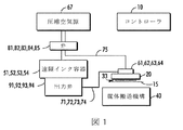
図1および図2は、コントローラ10と、印刷出力媒体15上に直接に、または中間転写面30上に、インク滴33を射出する複数のインクジェットを含む印字ヘッド20と、を含むインクジェット画像装置の実施形態の模式的ブロック図である。印刷媒体搬送機構40が印字ヘッド20に対して印刷媒体を移動させる。印字ヘッド20は、印字ヘッド20に流動的に連結された複数のオンボードインク容器61、62、63、64からインクを受け取る。オンボードインク容器61〜64は、それぞれ、各インク供給経路71、72、73、74を介して複数の遠隔インク容器51、52、53、54からインクを受け取る。
FIGS. 1 and 2 illustrate an inkjet imaging apparatus that includes a
図1および図2には示していないが、インクジェット画像装置は、遠隔インク容器51〜54にインクを供給するためのインク送出システムを含んでいる。一実施形態では、インクジェット印刷装置が相転移インク画像装置である。それに応じて、インク送出システムは、固形の相転移インクの少なくとも1色の少なくとも1つの供給源を有する相転移インク送出システムを含んでいる。また、相転移インク送出システムは、固形の相転移インクを溶かして液状にして、溶けたインクを適切な遠隔インク容器に送出するための溶融および制御装置(図示せず)を含んでいる。 Although not shown in FIGS. 1 and 2, the ink jet imaging device includes an ink delivery system for supplying ink to the remote ink containers 51-54. In one embodiment, the ink jet printing device is a phase change ink imaging device. Accordingly, the ink delivery system includes a phase change ink delivery system having at least one source of at least one color of solid phase change ink. The phase change ink delivery system also includes a melting and control device (not shown) for dissolving the solid phase change ink into a liquid and delivering the melted ink to a suitable remote ink container.
遠隔インク容器51〜54は、溶けた相転移インクをオンボードインク容器61〜64に供給するように構成されている。一実施形態では、遠隔インク容器51〜54が、例えば、圧縮空気源67により複数の弁81、82、83、84を介して提供される圧縮空気により、選択的に加圧できる。遠隔インク容器51〜54からオンボードインク容器61〜64に流れて印字ヘッド20の中で1つにまとめられるインクの流れが、例えば、流体により、または重力により加圧できる。オンボードインク容器61〜64へのインクの流れを制御するために出力弁91、92、93、94が設けてある。
The remote ink containers 51-54 are configured to supply melted phase change ink to the onboard ink containers 61-64. In one embodiment, the remote ink containers 51-54 can be selectively pressurized, for example, with compressed air provided by a
また、オンボードインク容器61〜64は、例えば、遠隔インク容器51〜54を選択的に加圧して、弁85を介して空気経路75を加圧することにより、選択的に加圧できる。あるいは、インク供給経路71〜74は、例えば、出力弁91〜94を閉じて、空気経路75を加圧することにより、閉じることができる。オンボードインク容器61〜64は、例えば、印字ヘッド20上で清浄動作またはパージ動作を実行するために加圧できる。オンボードインク容器61〜64および遠隔インク容器51〜54は、溶けた固体インクを貯蔵するように構成して加熱できる。また、インク供給経路71〜74および空気経路75は加熱できる。
Further, the on-
オンボードインク容器61〜64は、例えば、弁85を制御して空気経路75を大気に通気することにより、通常の印刷動作中に大気に通気される。また、オンボードインク容器61〜64は、インクを遠隔インク容器51〜54から加圧せずに移送する間に(すなわち、オンボードインク容器61〜64を加圧せずに、インクを移送するとき)大気に通気できる。
The on-
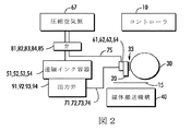
図2は、図1の実施形態と同様のインクジェット画像装置の実施形態の模式的ブロック図であり、印字ヘッド20により射出された滴を受け取るための転写ドラム30を含んでいる。印刷媒体搬送機構40が印刷媒体15に当接して印刷媒体15を転写ドラム30に接触させて、転写ドラム上に印刷された画像を、印刷媒体15に転写する。
FIG. 2 is a schematic block diagram of an inkjet imager embodiment similar to the embodiment of FIG. 1 and includes a
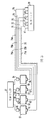
図3に模式的に示すように、インク供給経路71〜74および空気経路75の一部分が、多導管ケーブル70内の導管71A、72A、73A、74A、75Aとして実現できる。固体インクのインクジェット画像装置の実施形態では、これらの導管を加熱して、溶けたインクが印字ヘッド内の容器をあふれさせることができる温度に溶けたインクを維持する。
As schematically shown in FIG. 3, a part of the
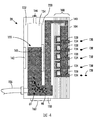
図4は、印字ヘッド20と単一のインク容器61との横断面図を示している。液体インクがインク供給経路を通っていったん印字ヘッドに到達すると、液体インクはオンボードインク容器61内に集められる。オンボードインク容器は、印刷媒体(図1)上に、または転写ドラム30(図2)のような中間転写部材上にインクを射出するための複数のインクジェットを含むジェットスタック100にインクが流体連通するように構成されている。
FIG. 4 shows a cross-sectional view of the
図4は、少なくとも1つのオンボードインク容器61を含む印字ヘッド20の実施形態を示している。出口98は、オンボードインク容器61とジェットスタック100とを流動的に連結している。ジェットスタック100は多くの方法で形成できるが、この実施例では、ステンレス鋼板および高分子層のような複数の積層板でインクジェットスタックを形成している。ジェットスタック100のステンレス鋼板および高分子層は、互いに一枚一枚突き合わせる形で位置合わせしながら積み重ねて、その後、ろう付け、または他の方法で一緒に接着され、機械的に一体的で使用可能なインクジェットスタックを形成する。
FIG. 4 illustrates an embodiment of the
各平板の中にエッチングされた空洞が、印字ヘッド用のインクジェットを規定する流路および通路を形成するように一列に並んでいる。より大きな空洞が、ジェットスタックの長さ全体にわたって走る、より大きな通路を形成するように一列に並んでいる。これらの、より大きな通路は、複数のインクジェット108にインクを供給するように配置されたインクマニホルド104である。各インクジェットと関連しており、インクジェットスタック開口プレート140内に形成された複数の開口部134が、インク滴138を射出する。
The etched cavities in each plate are aligned in a row to form flow paths and passages that define the ink jet for the printhead. Larger cavities are aligned to form a larger passageway that runs the entire length of the jet stack. These larger passages are
一実施形態では、例えば、真空発生装置などの圧力源を用いて、オンボード印字ヘッド容器61内の穴または通気孔144を介して、オンボード印字ヘッド容器61内のインクに負圧を加える、または真空にすることができる。それを通じてオンボード印字ヘッド容器61に負圧を導入する通気孔144は、それを通じてパージ動作を行うために正圧を導入するのと同じ通気孔である可能性がある。したがって、圧力源67は、双方向圧力源、真空源、または正負両圧をオンボード印字ヘッド容器61に供給するように構成された空気ポンプである可能性がある。しかしながら、別々の圧力源を使用して、オンボード印字ヘッド容器に正圧および負圧を導入できる。
In one embodiment, a negative pressure is applied to the ink in the on-
印字ヘッド20のオンボード印字ヘッド容器61は、溶けた相転移インク155を貯蔵するようになされた空間154を取り囲むために、さらなる側壁と協調する少なくとも1つの側壁152に連結された底壁150を、さらに含んでいる。溶けた相転移インク155は、容器154から遠く離れているが、曲がりやすい管類または他の導管156を用いて容器に流動的に連結された上述の遠隔インク容器のうちの1つから供給できる。
The
空間154を部分的に形成する側壁152に隣接してヒータ162を配置してある。ヒータ162は、空間154内に保持された相転移インクの液体状態を維持できるくらい十分高温の熱を提供する。また、図4に模式的に示すように、印字ヘッド20は循環装置163を含んでいる。循環装置163は、図5に示すように、インクの空間の中に流れを生成して、流路内でインクを移動させるように構成されている。循環装置163は、空間154内に、下方部分161から上方部分164への、および側方部分166のうちの一方への、矢印170で示す方向を有するインク流路またはインク循環を作り出す。また、インク循環装置165が前壁220に位置する可能性がある。インク循環装置163およびインク循環装置165は両方同時に使用でき、または一方もしくはもう一方を提供できる。また、ヒータ165はジェットスタックに近い側壁に位置する可能性がある。インク循環装置163および165はインク循環装置が位置する側壁の中央部分内にほぼ位置する可能性があり、大きさはインク循環装置が位置する側壁よりも小さい可能性があったり、または側壁全体を含む可能性があったりする。さらに、インク循環装置は側壁の表面に取り付けることができ、または側壁内に存在する空洞の中に埋め込むことができる。
A
たとえ遠隔インク容器からインクジェット108にいたるインク流路に沿ったさまざまな点でインクをフィルタ(図示せず)によりフィルタ処理できる場合でも、容器154内にすでに存在したり、フィルタを通過するほど小さかったり、またはインクの凍結/解凍サイクルで生成されたりした粒子が、インクジェットスタックに流れ込む可能性がある。このような粒子は、画像品質アーチファクトを引き起こす可能性がある噴射の欠落または噴射のスパッタリングなどの噴射問題を潜在的に引き起こす可能性があるとともに、このような粒子はインクジェットを詰まらせる可能性があり、インクジェットから媒体上にインクを射出できないようにする。循環装置163は容器内のインクを移動させるだけでなく、循環するインクと一緒に多くの粒子172も移動させる。この循環するインクは、粒子172がインクジェットスタックに吸い込まれる可能性が低い低流動性領域に粒子172を運ぶ。いくつかの実施形態では、気泡の流れなどの力を加えてインクの流れを駆動することにより、循環装置163がインクの流れを能動的に起こす。気泡の流れは、インク内の水分を泡立たせる、容器154の側壁上の局所的なヒータで作り出すことができる。インク内の水分は、固体の相転移インクのような、そのようなインクと混ざらない液中の水滴を含む可能性があり、またはインク内の水分は水性インクの主成分である水を含む可能性がある。他の実施形態では、能動ポンプを使用して、空気を送り込んで上昇気泡を形成することにより、または流体を送り込んで流れを作り出すことにより、インク循環を引き起こすことができる。他の実施形態では、液体インク内の温度勾配により引き起こされる流れを用いて、循環装置がインクの流れを受動的に起こすことができる。このような温度勾配は、ヒータ163を用いて作り出すことができる。最も速い速度が容器の出口98(図4)付近に存在しており、粒子が容器出口のこの領域から離れて、粒子が沈降できる低速領域の方に向かって移動するように、流れを確立する。
Even if the ink can be filtered by a filter (not shown) at various points along the ink flow path from the remote ink container to the
低速領域は、より大きな粒子が沈降することを可能にする。一実施形態では、ヒータ163が提供する局部加熱が、上方部分164に向かっての比較的急速で局所的なインクの上昇をもたらし、その後、側方部分166に向かって、その次に低流速領域の方に向かっての、より広い「下降気流」領域を引き起こす、より大きな面積の冷表面をもたらす。気泡の浮力は上昇するインクに局所的に作用するため急速な上昇流が気泡の流れにより自然に実現されるが、他方、下降する気泡はないため下向きのインクには作用しない。
The low speed region allows larger particles to settle. In one embodiment, the local heating provided by the
空間154の中に設置された分離器200が、第1のデバイダ202と、第2のデバイダ204と、を含むことができる。第1のデバイダ202は、全体として垂直な部分210と、全体として傾斜した部分212と、を含み、この全体として傾斜した部分212は、全体として垂直な部分210に連結されているが、それとは同一平面上にはない。第2のデバイダ204は同様に形成され、側壁215の近くに位置している。デバイダ202は空間154を仕切って、流れから外れて、デバイダ202と、オンボード印字ヘッド容器61の側壁216との間に捕捉される粒子状物質を集めるように形成された第1の領域214を作る。デバイダの反対側全体は、インクがほぼ妨げられることなく流れる上述の領域161を形成する。全体として垂直な部分210は、オンボード印字ヘッド容器61の底壁150のほかに図4の側壁152にも、前壁220にも連結されている。
The
図6で分かるように、デバイダ202内のほかにデバイダ204(図示せず)内にもスクリーン網またはフィルタ230を提供することにより、粒子とインクの間の分離が生じる可能性がある。インクからの望ましくない粒子の分離はスクリーン網230により提供されるが、その理由は、インクの主要な流れがスクリーン網を通り抜けると、選抜された粒子が第1の領域214に残り、スクリーン網を通り抜けた後には、きれいなインクが提供されるためである。オンボード印字ヘッド容器内の粒子量が一般に小さいため、長期にわたる搭載は大きな問題でない。
As can be seen in FIG. 6, by providing a screen network or filter 230 within the
デバイダ202および204は、全体として垂直な部分と、この全体として垂直な部分に対して傾斜した第2の部分と、を含むことを示しているが、不要な粒子を集めることができる領域であって、かつ循環するインクの流れを実質的に妨げない領域をデバイダが提供する限り、記載の部分はこのような構造を含む必要はない。例えば、傾斜した部分212を完全になくすことができるとともに、収集領域214を提供するために全体として垂直な部分を側壁に対して曲げることができる。
分離器200は、第1のビン206と、第2のビン208と、をさらに含むことができる。第1のビン206および第2のビン208のそれぞれは、底壁から所定の距離のところに位置しており、底壁には連結されていないが、前壁220から後壁152まで延びている。各ビンは、デバイダが形成する収集領域に隣接して収集領域ビンを形成して、矢印170の経路内の循環する粒子をビンにより捕捉でき、循環するインクから取り除くことができるようになっている。2つのビンを示しているが、分離器はゼロ個を含む任意の個数のビンを含むことができ、ビンがゼロ個の場合には、1つ以上のデバイダにより形成された領域内で粒子の収集が行われる。主要な流れから沈降ビン206および208内で分離することと、スクリーン網を通り抜けた後230に粒子を選抜して取り除くこととにより、実質的にきれいなインクを提供できる。
図7は、1つの望ましいインクの流れを提供するように構成されている循環装置165の模式図を示している。粒子循環は、高温のオンボード印字ヘッド容器61の側面、この場合、前壁220に沿って上向きに移動し、上壁を横切り、冷温側面または後壁152(図示せず)に沿って下向きに移動し、その後、高温側面220の下端の出発点に戻る経路に従う。方向を持った流れを提供するために、例えば、ヒータは、ヒータが結合している前壁よりも小さい長方形形状で形成でき、提供される温度は、底壁から空間の上端に向かって徐々に上昇し、後壁および側壁に向かって低下するようになっている。したがって、印字ヘッド容器および/または遠隔インク容器が、低価格で循環装置を含むように構成できる。このような装置は、印字ヘッドが使われておらず、顧客から見えない期間中に有効である可能性がある。
FIG. 7 shows a schematic diagram of a
インクの熱伝導率が低いため、水の空間の中への熱の移動は遅く、気泡発生のほとんどは、通常、アルミニウムであるオンボード印字ヘッド容器61の水滴と底壁150の間の接触点付近で見られる。水は高温インク内で沈殿でき、蒸気泡の結果として生じる生産は115℃のインク内の水に対して一般にうまく行われる。例えば、溶けた固体インク中に沈んでいる水分により生成される蒸気泡が、プールの底の巨視的な液滴として、またはアルミニウム表面の微視的構造内に吸収された水分として現れる可能性がある。より高い温度は水の急速な蒸発を引き起こすことができ、したがって、ヒータ163またはヒータ165の温度は、何らかの正確さで選択されなければならない。また、水がインクジェットスタックに吸い込まれて、水泡が噴射の欠落を引き起こすことがないように、水を管理する必要がある。
Due to the low thermal conductivity of the ink, heat transfer into the water space is slow, and most of the bubble generation is the contact point between the water droplets of the
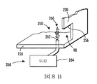
ジェットスタックの中への水の導入を大幅に軽減するために、印字ヘッドは底壁150に位置する水滴トラップ250を含むことができる。底壁150は、出口98から所定の距離だけ離れて底壁150から延びる側壁254を含む凹部またはくぼみ252を含んでいる。側壁254は、側壁254の上端が出口98の上端部分256にとどかないように、底壁から距離Dだけ延びている。距離Dは、側壁の片面上に水滴を捕捉することを提供するが、出口98を通るインクの流れを実質的に妨げない。しかしながら、水滴トラップ250が出口98から十分離れている場合には、側壁254の高さDの選択は、それほど重要ではなくなる。また、図8Bに示すように、ジェットスタックの中への水の導入を軽減するために、第2のトラップまたは毛細管構造260を使用できる。毛細管装置260は、底壁150のところに単一の小径オリフィス262を含むことができる。毛細管装置260は、蒸気または水の供給264に連結されており、オリフィス262から上へ出口98から離れるように蒸気泡266を駆動する力を提供する。水滴トラップ250または毛細管装置260のどちらか一方または両方を含むことができる。
In order to significantly reduce the introduction of water into the jet stack, the print head can include a
図9を参照すると、先行技術のインクジェット画像システム320を示している。本開示の目的のために、画像装置は、1つ以上のインクジェット印字ヘッドと、関連する固体インク供給とを使用するインクジェットプリンタの形をしている。しかしながら、溶けた相転移インクを供給する相転移インク容器と、本明細書に記載の印字ヘッドとは、インクジェットを使用して1つ以上の着色剤を媒体上に射出する他のさまざまなインクジェット画像装置のうちのいずれかに適用できる。画像装置は、インクジェットエジェクタに対する制御信号を生成する前に画像データを処理するための印刷エンジンを含んでいる。着色剤は、インクである可能性があり、または1つ以上の色素または顔料を含み、選択された媒体に塗布できる任意の好適な物質である可能性がある。着色剤は黒または他の任意の所望の色である可能性があり、所与の画像装置は複数の異なる着色剤を媒体に塗布できる可能性がある。媒体は、特に、普通紙、コート紙、光沢紙、またはトランスペアレンシーを含むさまざまな被印刷物のうちのいずれかを含むことができ、媒体は、シート、ロール、または他の物理的形式で利用できる可能性がある。
Referring to FIG. 9, a prior art
図9は、上述の、溶けた相転移インクを供給するための相転移インク容器と、印字ヘッドと、を含むことができる、ダイレクト・トゥー・シート(直接シートに印刷される)で、連続媒体の、相転移インクジェット画像システム320の簡略化した模式図である。媒体供給および媒体取り扱いシステムが、ウェブローラ308上に取り付けられた媒体のスプール310などの媒体供給源からの「被印刷物」(紙、プラスチック、または他の印刷可能な材料)の媒体Wの長い(すなわち、実質的に連続的な)ウェブを供給するように構成されている。片面印刷では、プリンタは供給ローラ308、媒体調節装置316、印刷ステーション320、印刷済みウェブ調節装置380、コーティングステーション360、および巻き取りユニット390を含んでいる。両面印刷運転では、巻き取りユニット390で巻き取る前に、ウェブ反転器384を使用してウェブをひっくり返して印刷ステーション320、印刷済みウェブ調節装置380、およびコーティングステーション360に媒体の第2の面を提示する。片面印刷運転では、媒体供給源310は、それを越えて媒体がプリンタの中を通って移動するローラの幅を実質的に覆う幅を有している。両面印刷運転では、媒体供給源はローラ幅の約半分であり、その理由は、ウェブが印刷ステーション320、印刷済みウェブ調節装置380、およびコーティングステーション360内のローラの半分を覆って移動し、その後、必要に応じて、ウェブ裏面の印刷、調節、およびコーティングを行うために、ウェブ反転器384でウェブをひっくり返して、印刷ステーション320、印刷済みウェブ調節装置380、およびコーティングステーション360の反対側のローラの残りの半分を覆ってウェブが移動できるようにする距離だけウェブを横方向にずらすためである。巻き取りユニット390は、プリンタおよび後続の処理を免除するために、ローラ上にウェブを巻き付けるように構成されている。
FIG. 9 is a direct-to-sheet (printed directly on) continuous medium that can include a phase change ink container for supplying melted phase change ink as described above and a printhead. FIG. 2 is a simplified schematic diagram of a phase change
媒体は、必要に応じて、媒体供給源310から巻き出すことができ、1つ以上のローラを回転させる図示されていないさまざまなモータにより動かすことができる。媒体調節装置は、ローラ312と、予熱器318と、を含んでいる。媒体は、一連の印字ヘッドモジュール321A、321B、321C、および321Dを含む印刷ステーション320を通って搬送され、各印字ヘッドモジュールは媒体の幅を横切って効果的に延びており、動いている媒体上に直接に(すなわち、中間部材またはオフセット部材を使用せずに)インクを付与できる。周知のように、印字ヘッドのそれぞれは、カラー印刷で通常使用される色のそれぞれに対して、単一色のインク、すなわち、シアン、マゼンタ、イエロー、およびブラック(CMYK)を射出できる。プリンタのコントローラ350が、4個の印字ヘッドの反対側の経路の部分の両側に設置されたローラに近接して取り付けられたエンコーダから速度データを受け取って、印字ヘッドを通過するときのウェブの位置を計算する。コントローラ350は、これらのデータを使用して、印字ヘッド内のインクジェットエジェクタを作動させるためのタイミング信号を生成して、異なる色のパターンの見当合わせ(位置合わせ)のために信頼できる精度で4色の色を射出できるようにして、媒体上に4原色の画像を形成する。発射信号により作動されるインクジェットエジェクタは、コントローラ350により処理される画像データに対応している。画像データは、プリンタに送信され、プリンタの構成要素であるスキャナ(図示せず)により生成され、または他の方法で生成されて、プリンタに送出できる。さまざまな可能な実施形態では、各原色用の印字ヘッドモジュールは、1つ以上の印字ヘッドを含むことができ、モジュール内の複数の印字ヘッドは単列または複数列配置に形成でき、複数列配置の印字ヘッドは交互に配置でき、印字ヘッドは2色以上を印刷でき、または印字ヘッドもしくは印字ヘッドの一部分は、スポットカラーの塗布などのために、プロセス方向Pを横断する方向に移動できるように取り付けることができる。
The media can be unwound from the
プリンタは「相転移インク」を使用でき、このことは、相転移インクが、室温では実質的に固体であり、受像表面上に噴射するために相転移インクの融点まで加熱したときには実質的に液体であるということを意味している。相転移インクの融点は、固体の相転移インクを溶かして液状または溶融形態にできる任意の温度である可能性がある。一実施形態では、相転移インクの融点が約70℃〜140℃である。他の実施形態では、画像装置に利用するインクがUV硬化性ゲルインクを含むことができる。また、ゲルインクは印字ヘッドのインクジェットエジェクタにより射出する前に加熱できる。本明細書で使用する場合、液体インクは、溶けた固体インク、加熱したゲルインク、または他の既知の形態のインク、例えば、水性インク、インクエマルジョン、インクサスペンション、インク溶液など、を示している。 The printer can use “phase change ink”, which is substantially solid at room temperature and is substantially liquid when heated to the melting point of the phase change ink for jetting onto the receiving surface. It means that. The melting point of the phase change ink can be any temperature at which the solid phase change ink can be melted into a liquid or molten form. In one embodiment, the melting point of the phase change ink is about 70 ° C to 140 ° C. In other embodiments, the ink utilized in the imaging device can include a UV curable gel ink. Also, the gel ink can be heated before being ejected by the inkjet ejector of the print head. As used herein, liquid ink refers to melted solid ink, heated gel ink, or other known forms of ink, such as aqueous inks, ink emulsions, ink suspensions, ink solutions, and the like.
実質的に印字ヘッドの反対側の、媒体の裏面に配置されており、通常、バーまたはロールの形をした支持部材324A〜324Dが、各印字ヘッドモジュールに関連している。各支持部材は、支持部材に向かい合った印字ヘッドから所定の距離に媒体を位置付けるために使用される。各支持部材は、熱エネルギーを放射して媒体を所定温度まで加熱するように構成でき、この所定温度は、実際的な一実施形態では、約40℃から約60℃の範囲である。さまざまな支持部材を、個々に、またはまとめて、制御できる。予熱器318、印字ヘッド、支持部材324(加熱される場合)、および周囲空気が組み合わさって、印刷ステーション320の反対側の経路の部分に沿って媒体を約40℃〜70℃の所定温度範囲に維持する。
Associated with each printhead module is a
印刷ステーション320の印字ヘッドから、さまざまな色のインクを受け取るために部分的に画像化済みの媒体が動くとき、媒体の温度を所与の範囲内に維持する。受け取る側の媒体温度よりも、通常、大幅に高い温度の印字ヘッドからインクを射出する。その結果として、インクは媒体を加熱する。そのため、さまざまな実施形態では、媒体温度を所定範囲内に維持するために他の温度調節装置を使用する。印刷ゾーン320の後には媒体経路に沿って1つ以上の「中間ヒータ」330がある。中間ヒータ330は、媒体の温度を制御するために、接触熱、放射熱、伝導熱、および/または対流熱を使用できる。スプレッダ(展着装置)340を通って媒体上のインクを送るときに、中間ヒータ330は所望の特性に適した温度まで媒体上に載っているインクを昇温する。一実施形態では、中間ヒータの目標温度に対する有効範囲が約35℃〜約80℃である。
As the partially imaged media moves to receive various colors of ink from the print head of the
中間ヒータ330の直後には、定着アセンブリまたはスプレッダ340が、媒体に熱および/または圧力を加えて、画像を媒体に定着させるように構成されている。定着アセンブリは、加熱した、または加熱していない圧力ローラ、放射ヒータ、加熱ランプ、およびその種の他のものを含む、画像を媒体に定着させるのに適した任意の装置または器具を含むことができる。
Immediately following the
また、スプレッダ340は画像側ローラ342に関連する清浄/注油ステーション348を含むことができる。清浄/注油ステーション348はローラ表面を清浄して、および/または何らかの離型剤または他の材料の層をローラ表面に塗布する。離型剤材料は、約10〜200センチポアズの粘度を有するアミノシリコーン油である可能性がある。ほんの少量の油だけが必要であり、媒体により運ばれる油はA4サイズ1ページあたり約1〜10mgだけである。
The
コーティングステーション360は印刷済み媒体に透明なインクを塗布する。この透明なインクは、プリンタを出た後の汚損または他の環境悪化から印刷済み媒体を保護するのを助ける。透明なインクのオーバレイは、取り扱い時に汚れたり、および/または裏移りしたりしても、下部にある画像の見た目に影響を与えない可能性があるインクの犠牲層として機能する。コーティングステーション360は、ローラ、またはパターン内に透明なインクを射出する印字ヘッド370のどちらかを用いて透明なインクを塗布する。インクには、すべての着色剤が欠けているかどうかにかかわらず、本開示の目的のために、透明なインクは最終的に印刷される色に対して最小限の影響しか与えない実質的に透明な保護膜インクとして機能上規定される。
The
スプレッダ340を通過した後は、印刷済み媒体をローラ上に巻き付けてシステムを出る(片面印刷)か、または印刷済み媒体をウェブ反転器384に導いて反転させて、ローラの他の部分に位置をずらして、印字ヘッド、中間ヒータ、スプレッダ、およびコーティングステーションを経由しての2回目の通過を行うか、のどちらかが可能である。その後、巻き取りユニット390により両面印刷済みの材料をローラ上に巻き付けてシステムを出ることができる。あるいは、媒体を裁断すること、製本すること、落丁を調べること、および/またはホチキスでとじることなどの作業を行う他の処理ステーションに媒体を導くことができる。
After passing through the
装置320のさまざまなサブシステム、構成要素、および機能の運転および制御が、コントローラ350の助けを借りて実行される。コントローラ350は、プログラムされた命令を実行する一般的なまたは特殊なプログラム可能プロセッサを用いて実現できる。プログラムされた機能を実行するのに必要な命令およびデータは、プロセッサまたはコントローラに関連するメモリ内に通常保存される。プロセッサ、それらのメモリ、およびインタフェース回路が、上述の機能を実行するためのコントローラおよび/または印刷エンジンを構成する。これらの構成要素は、プリント基板カード上に提供でき、または特定用途向け集積回路(ASIC)内の回路として提供できる。回路のそれぞれは個別のプロセッサを用いて実現でき、または同じプロセッサ上に複数の回路を実現できる。あるいは、回路はVLSI回路内に設けた個別の構成要素または回路を用いて実現できる。また、プロセッサ、ASIC、個別の構成要素、またはVLSI回路の組み合わせを用いて本明細書に記載の回路を実現できる。
The operation and control of the various subsystems, components, and functions of the
また、画像システム320は、印刷済みのウェブを画像化するための上述のシステムと同様の方法で構成される光学的画像システム354を含むことができる。光学的画像システムは、例えば、受け取る側の部材上に印字ヘッドアセンブリのインクジェットにより噴射されたインク滴の存在、強度、および/または位置などを検出するように構成されている。
The
Claims (6)
少なくとも1つの側壁と、
前記溶けた相転移インクを貯蔵する前記空間を取り囲むために前記少なくとも1つの側壁に連結された底壁と、
前記溶けた相転移インクの流れを前記空間の中に生成するように構成された循環装置と、
第1の側と第2の側とを有するデバイダと、を含み、
前記デバイダは、前記底壁に立設されて、前記側壁、前記底壁及び前壁に連結し、
前記デバイダと、前記側壁との間には、領域が構成され、
前記相転移インク容器は、前記前壁の下端に設けられた出口によってジェットスタックと連結し、
前記循環装置は、前記側壁と、前記底壁とのうちの一方に沿って配置されて、前記相転移インク容器に遠隔インク容器から供給された前記相転移インクに、前記空間に下方部分から上方部分への前記相転移インクの流れと、該上方部分から前記領域側に向けた側方部分への前記相転移インクの流れとを生成し、
前記デバイダは、前記循環装置によって生成される相転移インクの流れを、前記デバイダの前記第1の側に沿って第1方向に移動させると共に、前記デバイダの前記第2の側に沿って第2方向に移動させるように前記空間内に配置され、前記第1方向は、前記第2方向と反対方向であり、前記第2方向での前記流れの動きは、粒子状物質が前記流れから外れることが可能になるように前記第1方向での前記流れの動きよりも遅く、前記デバイダが、前記流れから外れた前記粒子状物質が前記デバイダの前記第1の側に沿って前記流れに戻るのを妨げる、溶けた相転移インクを印字ヘッドに供給するように構成された、相転移インク容器。 A phase change ink container surrounding a space for storing melted phase change ink in a print head,
At least one side wall;
A bottom wall coupled to the at least one side wall to surround the space for storing the phase change ink melted above,
A circulation device configured to generate a flow of the melted phase change ink in the space ;
A divider having a first side and a second side;
The divider is erected on the bottom wall and connected to the side wall, the bottom wall and the front wall,
A region is formed between the divider and the side wall,
The phase change ink container is connected to a jet stack by an outlet provided at a lower end of the front wall,
The circulation device is disposed along one of the side wall and the bottom wall, and the phase change ink supplied from the remote ink container to the phase change ink container is moved upward from a lower part to the space. Generating a flow of the phase change ink to a portion and a flow of the phase change ink from the upper portion to a side portion toward the region side;
The divider, the flow of a phase change ink generated by the circulation device is moved in a first direction along the first side of the divider, the second along the second side of the divider disposed in the space to so that is moved in the direction, the first direction is a second direction opposite to the direction, movement of the flow in the second direction disengages particulate matter from the stream Slower than the flow movement in the first direction so that it is possible, the divider returns the particulate matter out of the flow to the flow along the first side of the divider. A phase change ink container configured to supply melted phase change ink to a print head.
前記相転移インク容器は、
少なくとも1つの側壁を含み、
前記溶けた相転移インクを貯蔵する前記空間を取り囲むために前記少なくとも1つの側壁に連結された底壁を含み、ここで、前記少なくとも1つの側壁と、前記底壁と、のうちの一方は、前記相転移インク容器の外部の溶けた相転移インクの流れを提供するための入口を含み、
前記溶けた相転移インクの流れを前記空間の中に生成するように構成された循環装置を含み、
第1の側と第2の側とを有するデバイダを含み、
前記デバイダは、前記底壁に立設されて、前記側壁、前記底壁及び前壁に連結し、
前記デバイダと、前記側壁との間には、領域が構成され、
前記相転移インク容器は、前記前壁の下端に設けられた出口によってジェットスタックと連結し、
前記循環装置は、前記側壁と、前記底壁とのうちの一方に沿って配置されて、前記相転移インク容器に遠隔インク容器から前記入口を介して供給された前記相転移インクに、前記空間に下方部分から上方部分への前記相転移インクの流れと、該上方部分から前記領域側に向けた側方部分への前記相転移インクの流れとを生成し、
前記デバイダは、前記循環装置によって生成される相転移インクの流れを、前記デバイダの前記第1の側に沿って第1方向に移動させると共に、前記デバイダの前記第2の側に沿って第2方向に移動させるように前記空間内に配置され、
前記第1方向は、前記第2方向と反対方向であり、前記第2方向での前記流れの動きは、粒子状物質が前記流れから外れることが可能になるように前記第1方向での前記流れの動きよりも遅く、前記デバイダが、前記流れから外れた前記粒子状物質が前記デバイダの前記第1の側に沿って前記流れに戻るのを妨げ、
前記出口に連結され、溶けた相転移インクの滴を前記受像部材上に放出するための複数のインク滴発生装置を含む、
印字ヘッド。 A print head comprising a phase change ink container for use in an image device for depositing a melted phase change ink on an image receiving member and surrounding a space for storing the melted phase change ink ,
The phase change ink container includes:
Including at least one sidewall,
Wherein said at least one concatenated bottom wall to the side walls to surround the space for storing the phase change ink melted above, wherein said at least one sidewall, said bottom wall, one of, includes inlet port for providing a flow of external melted phase change ink of the phase change ink container,
A circulator configured to generate a flow of the melted phase change ink in the space ;
Including a divider having a first side and a second side;
The divider is erected on the bottom wall and connected to the side wall, the bottom wall and the front wall,
A region is formed between the divider and the side wall,
The phase change ink container is connected to a jet stack by an outlet provided at a lower end of the front wall,
The circulation device is disposed along one of the side wall and the bottom wall, and the space is supplied to the phase change ink supplied from the remote ink container to the phase change ink container through the inlet. A flow of the phase change ink from the lower part to the upper part and a flow of the phase change ink from the upper part to the side part toward the region side,
The divider, the flow of a phase change ink generated by the circulation device is moved in a first direction along the first side of the divider, the second along the second side of the divider disposed in the space to so that is moved in the direction,
The first direction is opposite to the second direction, and the movement of the flow in the second direction is such that the particulate material is allowed to deviate from the flow. Slower than the flow movement, the divider prevents the particulate matter deviating from the flow from returning to the flow along the first side of the divider;
A plurality of ink drop generators coupled to the outlet for discharging molten phase change ink drops onto the image receiving member;
Print head.
Applications Claiming Priority (2)
| Application Number | Priority Date | Filing Date | Title |
|---|---|---|---|
| US13/315,601 | 2011-12-09 | ||
| US13/315,601 US8696098B2 (en) | 2011-12-09 | 2011-12-09 | Printhead having particle circulation with separation |
Publications (3)
| Publication Number | Publication Date |
|---|---|
| JP2013121719A JP2013121719A (en) | 2013-06-20 |
| JP2013121719A5 JP2013121719A5 (en) | 2016-01-14 |
| JP5969901B2 true JP5969901B2 (en) | 2016-08-17 |
Family
ID=48571603
Family Applications (1)
| Application Number | Title | Priority Date | Filing Date |
|---|---|---|---|
| JP2012253526A Expired - Fee Related JP5969901B2 (en) | 2011-12-09 | 2012-11-19 | Print head with particle circulation with separation |
Country Status (4)
| Country | Link |
|---|---|
| US (1) | US8696098B2 (en) |
| JP (1) | JP5969901B2 (en) |
| KR (1) | KR101860953B1 (en) |
| CN (1) | CN103158353B (en) |
Families Citing this family (3)
| Publication number | Priority date | Publication date | Assignee | Title |
|---|---|---|---|---|
| US9254674B2 (en) | 2014-02-25 | 2016-02-09 | Palo Alto Research Center Incorporated | Reservoir having particle trapping features |
| US9579902B1 (en) * | 2016-02-16 | 2017-02-28 | Xerox Corporation | Cascading reservoirs for solid-ink printers |
| KR102236802B1 (en) | 2019-11-25 | 2021-04-06 | 건국대학교 산학협력단 | Device and method for feature extraction of data for diagnostic models |
Family Cites Families (27)
| Publication number | Priority date | Publication date | Assignee | Title |
|---|---|---|---|---|
| US4814786A (en) * | 1987-04-28 | 1989-03-21 | Spectra, Inc. | Hot melt ink supply system |
| EP0506403B1 (en) * | 1991-03-25 | 1995-08-23 | Tektronix, Inc. | Method and apparatus for providing phase change ink to an ink jet printer |
| US5453159A (en) | 1993-11-04 | 1995-09-26 | International Paper Company | Deinking of recycled pulp |
| US5659346A (en) * | 1994-03-21 | 1997-08-19 | Spectra, Inc. | Simplified ink jet head |
| US5512171A (en) | 1995-01-31 | 1996-04-30 | Essop; Saleam | Particle separator |
| US6709869B2 (en) | 1995-12-18 | 2004-03-23 | Tecan Trading Ag | Devices and methods for using centripetal acceleration to drive fluid movement in a microfluidics system |
| JP3469585B2 (en) * | 1997-05-23 | 2003-11-25 | ガメラ バイオサイエンス コーポレイション | Apparatus and method for using centripetal acceleration to drive flow motion in microfluidics systems |
| US6042733A (en) | 1997-08-26 | 2000-03-28 | Tucker; Randall L. | Sediment filtering system |
| US6733116B1 (en) | 1998-10-16 | 2004-05-11 | Silverbrook Research Pty Ltd | Ink jet printer with print roll and printhead assemblies |
| JP2000071477A (en) | 1998-06-17 | 2000-03-07 | Canon Inc | Ink supplying device and ink jet recording head |
| US6207032B1 (en) | 1998-10-01 | 2001-03-27 | Kvaerner Process Systems, Inc. | Electrostatic/mechanical emulsion treating method and apparatus |
| CN1234530C (en) | 2001-05-09 | 2006-01-04 | 松下电器产业株式会社 | Ink jet device, ink and method of manufacturing electronic component using the device and the ink |
| US7007759B2 (en) | 2003-09-11 | 2006-03-07 | R3 Pump Technologies, Llc | Method and system for directing fluid flow |
| US7607766B2 (en) | 2004-05-04 | 2009-10-27 | Kodak Graphic Communications Canada Company | Method and print head for flow conditioning a fluid |
| JP3840237B2 (en) * | 2004-06-02 | 2006-11-01 | キヤノン株式会社 | Liquid storage container and recording apparatus using the liquid storage container |
| US20050269557A1 (en) | 2004-06-03 | 2005-12-08 | Perrin Craig L | Sediment Fence with Skirt |
| US7258800B1 (en) | 2004-08-26 | 2007-08-21 | Herbst Robert J | Electrocoagulation waste water batch tank treatment system |
| EP1831025B1 (en) | 2004-12-17 | 2008-05-07 | Agfa Graphics Nv | Ink circulation system for inkjet printing |
| JP2007237552A (en) | 2006-03-08 | 2007-09-20 | Fuji Xerox Co Ltd | Liquid droplet discharge unit, and droplet discharge apparatus |
| US7801465B2 (en) | 2007-07-30 | 2010-09-21 | Hewlett-Packard Development Company, L.P. | Condensate separation |
| GB0724606D0 (en) | 2007-12-18 | 2008-01-30 | Xennia Technology Ltd | Recirculating ink system for industrial inkjet printing |
| AT507142B1 (en) | 2008-08-14 | 2011-05-15 | Durst Phototechnik Digital Technology Gmbh | INK SUPPLY SYSTEM AND METHOD FOR CLEANING AN INK SUPPLY SYSTEM |
| US8024968B2 (en) | 2009-02-02 | 2011-09-27 | Xerox Corporation | Apparatus and method for detecting ink in a reservoir |
| US8136934B2 (en) * | 2009-02-18 | 2012-03-20 | Xerox Corporation | Waste phase change ink recycling |
| JP2010208265A (en) * | 2009-03-12 | 2010-09-24 | Seiko Epson Corp | Liquid storing container |
| US8371683B2 (en) | 2010-12-23 | 2013-02-12 | Palo Alto Research Center Incorporated | Particle removal device for ink jet printer |
| CN202053683U (en) * | 2011-04-11 | 2011-11-30 | 深圳市润天智图像技术有限公司 | Ink receiving device of inkjet printer and inkjet printer |
-
2011
- 2011-12-09 US US13/315,601 patent/US8696098B2/en active Active
-
2012
- 2012-11-19 JP JP2012253526A patent/JP5969901B2/en not_active Expired - Fee Related
- 2012-12-03 CN CN201210510049.2A patent/CN103158353B/en not_active Expired - Fee Related
- 2012-12-07 KR KR1020120142364A patent/KR101860953B1/en active IP Right Grant
Also Published As
| Publication number | Publication date |
|---|---|
| KR101860953B1 (en) | 2018-05-24 |
| KR20130065624A (en) | 2013-06-19 |
| CN103158353A (en) | 2013-06-19 |
| JP2013121719A (en) | 2013-06-20 |
| US20130147886A1 (en) | 2013-06-13 |
| US8696098B2 (en) | 2014-04-15 |
| CN103158353B (en) | 2015-12-02 |
Similar Documents
| Publication | Publication Date | Title |
|---|---|---|
| JP5620726B2 (en) | Liquid discharge head and ink jet recording apparatus | |
| US7360887B2 (en) | Image forming apparatus and method | |
| JP5381678B2 (en) | Image forming apparatus | |
| JP5312365B2 (en) | Recycling waste phase change ink | |
| US8282188B2 (en) | Inkjet head cleaning apparatus, image recording apparatus and inkjet head cleaning method | |
| US20070052779A1 (en) | Ink supplying unit and inkjet image forming apparatus including the same | |
| JP2011079169A (en) | Ink-jet recording device | |
| JP6034745B2 (en) | System and method for printing full color composite images in an ink jet printer | |
| US20100245463A1 (en) | Inkjet head cleaning apparatus, image recording apparatus and inkjet head cleaning method | |
| JP5969901B2 (en) | Print head with particle circulation with separation | |
| JP2801231B2 (en) | Image recording device | |
| JP2017209844A (en) | Liquid discharge device | |
| CN103660585A (en) | Phase change ink reservoir for a phase change inkjet printer | |
| CN103587245B (en) | There is printhead cleaning ink being incorporated into the staged flow path of collection tray | |
| JP5359722B2 (en) | Image forming apparatus | |
| US8240813B2 (en) | Directed flow drip bib for an inkjet printhead | |
| US11577519B2 (en) | Liquid discharge device, image forming apparatus incorporating the liquid discharge device, and method of supplying liquid | |
| US8226187B2 (en) | Tilt mitigation methods to control reservoir ink level and printhead pressure | |
| WO2017061265A1 (en) | Inkjet recording device | |
| JP5936512B2 (en) | Liquid discharge head and image recording apparatus | |
| US8827439B2 (en) | Self-cleaning media perforator | |
| JP2017217810A (en) | Liquid discharge unit and device for discharging liquid | |
| US8641178B1 (en) | Ink receptacle for collecting and controllably releasing purged ink | |
| US9073327B1 (en) | Printhead cleaning system having an elongated member connected to a vacuum source | |
| JP6931488B2 (en) | Liquid discharge device and liquid exchange method |
Legal Events
| Date | Code | Title | Description |
|---|---|---|---|
| RD04 | Notification of resignation of power of attorney |
Free format text: JAPANESE INTERMEDIATE CODE: A7424 Effective date: 20140424 |
|
| A521 | Request for written amendment filed |
Free format text: JAPANESE INTERMEDIATE CODE: A523 Effective date: 20151117 |
|
| A621 | Written request for application examination |
Free format text: JAPANESE INTERMEDIATE CODE: A621 Effective date: 20151117 |
|
| A871 | Explanation of circumstances concerning accelerated examination |
Free format text: JAPANESE INTERMEDIATE CODE: A871 Effective date: 20151117 |
|
| A975 | Report on accelerated examination |
Free format text: JAPANESE INTERMEDIATE CODE: A971005 Effective date: 20160104 |
|
| A131 | Notification of reasons for refusal |
Free format text: JAPANESE INTERMEDIATE CODE: A131 Effective date: 20160112 |
|
| A521 | Request for written amendment filed |
Free format text: JAPANESE INTERMEDIATE CODE: A523 Effective date: 20160406 |
|
| TRDD | Decision of grant or rejection written | ||
| A01 | Written decision to grant a patent or to grant a registration (utility model) |
Free format text: JAPANESE INTERMEDIATE CODE: A01 Effective date: 20160621 |
|
| A61 | First payment of annual fees (during grant procedure) |
Free format text: JAPANESE INTERMEDIATE CODE: A61 Effective date: 20160708 |
|
| R150 | Certificate of patent or registration of utility model |
Ref document number: 5969901 Country of ref document: JP Free format text: JAPANESE INTERMEDIATE CODE: R150 |
|
| R250 | Receipt of annual fees |
Free format text: JAPANESE INTERMEDIATE CODE: R250 |
|
| R250 | Receipt of annual fees |
Free format text: JAPANESE INTERMEDIATE CODE: R250 |
|
| LAPS | Cancellation because of no payment of annual fees |