JP5965320B2 - Thermoelectric generator for aircraft bleed system - Google Patents
Thermoelectric generator for aircraft bleed system Download PDFInfo
- Publication number
- JP5965320B2 JP5965320B2 JP2012542013A JP2012542013A JP5965320B2 JP 5965320 B2 JP5965320 B2 JP 5965320B2 JP 2012542013 A JP2012542013 A JP 2012542013A JP 2012542013 A JP2012542013 A JP 2012542013A JP 5965320 B2 JP5965320 B2 JP 5965320B2
- Authority
- JP
- Japan
- Prior art keywords
- air
- bleed
- thermoelectric generator
- bleed air
- ram
- Prior art date
- Legal status (The legal status is an assumption and is not a legal conclusion. Google has not performed a legal analysis and makes no representation as to the accuracy of the status listed.)
- Active
Links
Images


Classifications
-
- B—PERFORMING OPERATIONS; TRANSPORTING
- B64—AIRCRAFT; AVIATION; COSMONAUTICS
- B64D—EQUIPMENT FOR FITTING IN OR TO AIRCRAFT; FLIGHT SUITS; PARACHUTES; ARRANGEMENTS OR MOUNTING OF POWER PLANTS OR PROPULSION TRANSMISSIONS IN AIRCRAFT
- B64D13/00—Arrangements or adaptations of air-treatment apparatus for aircraft crew or passengers, or freight space, or structural parts of the aircraft
- B64D13/06—Arrangements or adaptations of air-treatment apparatus for aircraft crew or passengers, or freight space, or structural parts of the aircraft the air being conditioned
-
- B—PERFORMING OPERATIONS; TRANSPORTING
- B64—AIRCRAFT; AVIATION; COSMONAUTICS
- B64D—EQUIPMENT FOR FITTING IN OR TO AIRCRAFT; FLIGHT SUITS; PARACHUTES; ARRANGEMENTS OR MOUNTING OF POWER PLANTS OR PROPULSION TRANSMISSIONS IN AIRCRAFT
- B64D37/00—Arrangements in connection with fuel supply for power plant
- B64D37/32—Safety measures not otherwise provided for, e.g. preventing explosive conditions
-
- B—PERFORMING OPERATIONS; TRANSPORTING
- B64—AIRCRAFT; AVIATION; COSMONAUTICS
- B64D—EQUIPMENT FOR FITTING IN OR TO AIRCRAFT; FLIGHT SUITS; PARACHUTES; ARRANGEMENTS OR MOUNTING OF POWER PLANTS OR PROPULSION TRANSMISSIONS IN AIRCRAFT
- B64D41/00—Power installations for auxiliary purposes
-
- B—PERFORMING OPERATIONS; TRANSPORTING
- B64—AIRCRAFT; AVIATION; COSMONAUTICS
- B64D—EQUIPMENT FOR FITTING IN OR TO AIRCRAFT; FLIGHT SUITS; PARACHUTES; ARRANGEMENTS OR MOUNTING OF POWER PLANTS OR PROPULSION TRANSMISSIONS IN AIRCRAFT
- B64D13/00—Arrangements or adaptations of air-treatment apparatus for aircraft crew or passengers, or freight space, or structural parts of the aircraft
- B64D13/06—Arrangements or adaptations of air-treatment apparatus for aircraft crew or passengers, or freight space, or structural parts of the aircraft the air being conditioned
- B64D2013/0603—Environmental Control Systems
- B64D2013/0618—Environmental Control Systems with arrangements for reducing or managing bleed air, using another air source, e.g. ram air
-
- B—PERFORMING OPERATIONS; TRANSPORTING
- B64—AIRCRAFT; AVIATION; COSMONAUTICS
- B64D—EQUIPMENT FOR FITTING IN OR TO AIRCRAFT; FLIGHT SUITS; PARACHUTES; ARRANGEMENTS OR MOUNTING OF POWER PLANTS OR PROPULSION TRANSMISSIONS IN AIRCRAFT
- B64D13/00—Arrangements or adaptations of air-treatment apparatus for aircraft crew or passengers, or freight space, or structural parts of the aircraft
- B64D13/06—Arrangements or adaptations of air-treatment apparatus for aircraft crew or passengers, or freight space, or structural parts of the aircraft the air being conditioned
- B64D2013/0603—Environmental Control Systems
- B64D2013/0685—Environmental Control Systems with ozone control
-
- Y—GENERAL TAGGING OF NEW TECHNOLOGICAL DEVELOPMENTS; GENERAL TAGGING OF CROSS-SECTIONAL TECHNOLOGIES SPANNING OVER SEVERAL SECTIONS OF THE IPC; TECHNICAL SUBJECTS COVERED BY FORMER USPC CROSS-REFERENCE ART COLLECTIONS [XRACs] AND DIGESTS
- Y02—TECHNOLOGIES OR APPLICATIONS FOR MITIGATION OR ADAPTATION AGAINST CLIMATE CHANGE
- Y02T—CLIMATE CHANGE MITIGATION TECHNOLOGIES RELATED TO TRANSPORTATION
- Y02T50/00—Aeronautics or air transport
- Y02T50/40—Weight reduction
-
- Y—GENERAL TAGGING OF NEW TECHNOLOGICAL DEVELOPMENTS; GENERAL TAGGING OF CROSS-SECTIONAL TECHNOLOGIES SPANNING OVER SEVERAL SECTIONS OF THE IPC; TECHNICAL SUBJECTS COVERED BY FORMER USPC CROSS-REFERENCE ART COLLECTIONS [XRACs] AND DIGESTS
- Y02—TECHNOLOGIES OR APPLICATIONS FOR MITIGATION OR ADAPTATION AGAINST CLIMATE CHANGE
- Y02T—CLIMATE CHANGE MITIGATION TECHNOLOGIES RELATED TO TRANSPORTATION
- Y02T50/00—Aeronautics or air transport
- Y02T50/50—On board measures aiming to increase energy efficiency
Description
本願は概して電力系統に関し、さらに具体的には発電すると同時にラム空気の吸気量を減らす、熱電発電機の航空機ブリードシステムへの統合化に関するものである。 The present application relates generally to power systems, and more specifically to the integration of thermoelectric generators into aircraft bleed systems that generate ram air while simultaneously generating electricity.
ブリード空気は航空機の多数のシステムによって使用され得る。例えば、窒素発生システムにおいて、ブリード空気を使用して窒素を発生させて燃料タンクを不活性化し、酸素、燃料蒸気、及び点火源の可燃性結合から発生する潜在的な危険状態を除去することができる。作動中、窒素発生システムはブリード空気を抽出し、その空気の温度を外のラム空気の使用を通して空気交換器内で冷却することができる。ブリード空気の温度の冷却工程では、排気とともに廃熱が放出されうる。調節された空気は次に例えば空気分離ステージ等の加圧チャンバに供給することができ、ここで加圧チャンバから放出された空気、又は加圧チャンバの外に出た空気が窒素富化空気及び酸素富化空気に分離されうる。窒素富化空気はその後燃料タンクに供給することができる。 Bleed air can be used by a number of aircraft systems. For example, in a nitrogen generation system, bleed air can be used to generate nitrogen to inactivate the fuel tank, eliminating potential hazardous conditions arising from flammable combinations of oxygen, fuel vapor, and ignition sources. it can. In operation, the nitrogen generation system can extract bleed air and cool the temperature of the air in the air exchanger through the use of external ram air. In the cooling process of the temperature of the bleed air, waste heat can be released together with the exhaust. The conditioned air can then be supplied to a pressurized chamber, such as an air separation stage, where the air released from the pressurized chamber or the air exiting the pressurized chamber is nitrogen-enriched air and It can be separated into oxygen-enriched air. Nitrogen-enriched air can then be supplied to the fuel tank.
ラム空気は空気間熱交換器内部で冷却液として用いることができる。航空機はラム空気吸気システムを用いて、航空機の動きに応じて空気を取り込むことができる。空気は空気間熱交換器につながる導管を通じて流すことができる。ラム空気吸気システムの設計が適切であれば、航空機が作動中に空気媒体の中を移動している間、十分な気流が空気間熱交換器に供給されうる。空気抵抗は、空気抵抗によって発生する抵抗量を克服するのに使用されるエネルギー量に直接の影響を与えうる。この結果、ブリード空気を冷却するためにさらに多くのラム空気が取り込まれる時に、航空機にかかる抵抗はより大きくなる。 Ram air can be used as a coolant inside the air-to-air heat exchanger. An aircraft can use a ram air intake system to take in air as the aircraft moves. Air can flow through a conduit leading to an air-to-air heat exchanger. If the design of the ram air intake system is appropriate, sufficient airflow can be supplied to the air-to-air heat exchanger while the aircraft is moving through the air medium during operation. Air resistance can directly affect the amount of energy used to overcome the amount of resistance generated by air resistance. As a result, the resistance on the aircraft is greater when more ram air is taken in to cool the bleed air.
したがって、上述した課題を克服するシステム及び方法を提供する必要がある。 Therefore, there is a need to provide a system and method that overcomes the aforementioned problems.
発電装置であって、ブリード空気システムと、ラム空気とブリード空気との間の温度差を利用して発電する、ブリード空気システムに連結された熱電装置を含む。 A power generation device includes a bleed air system and a thermoelectric device coupled to the bleed air system for generating power utilizing a temperature difference between ram air and bleed air.
航空機ブリードシステム上で発電する方法であって、ラム空気を受け入れ、ブリード空気を受け入れ、航空機ブリードシステムに連結された熱電発電機にラム空気及びブリード空気を通して発電させることを含む方法。 A method of generating electricity on an aircraft bleed system, the method comprising receiving ram air, receiving bleed air, and causing a thermoelectric generator coupled to the aircraft bleed system to generate electricity through the ram air and bleed air.
ブリード空気を受け入れる空気間熱交換器を有する熱電装置を含むシステムであって、前記熱電装置が前記ブリード空気を冷却している間に、前記ブリード空気とラム空気との間の温度差から電気エネルギーを発生させるシステム。 A system comprising a thermoelectric device having an air-to-air heat exchanger for receiving bleed air, wherein electrical energy is derived from a temperature difference between the bleed air and ram air while the thermoelectric device cools the bleed air. System to generate.
特徴、機能及び利点は、本発明の様々な実施形態において個別に達成することができる、又は更に別の実施形態と組み合わせることができる。 The features, functions and advantages can be achieved individually in the various embodiments of the invention or may be combined with further embodiments.
本願を特徴づけていると思われる新規特性は添付の請求項に記載されている。下記の説明において、類似のパーツはそれぞれ、明細書及び図面全体において同じ番号が振られている。図面は必ずしも原寸に比例しておらず、特定の図面を明確に、また簡潔にするために、拡大した形態又は一般化した形態で図示している場合がある。本願自体だけでなく、使用の好ましいモード、更なる目的及びその利点はしかしながら、添付の図面と併せて読むときに、図示した実施形態の下記の詳細説明を参照することによって最適に理解される。
The novel features believed to characterize the present application are set forth in the appended claims. In the description that follows, like parts are numbered the same throughout the specification and the drawings. The drawings are not necessarily to scale, and certain drawings may be shown in an expanded or generalized form for clarity and brevity. The preferred mode of use, further objects and advantages thereof, as well as the present application itself, however, are best understood by reference to the following detailed description of the illustrated embodiments when read in conjunction with the accompanying drawings.
添付の図面と関連して下に記載した説明は、本願の現在好適な実施形態の説明であって、本願を構成する及び/又は用いることができる唯一の形態として示すものではない。この説明には、実例となる実施形態と関連して本願を構成し、作動させるための機能及びステップシーケンスが記載される。当然ながら、これもまた本願の精神及び範囲内に含まれるべきである異なる実施形態によって同じ又は同等の機能及びシーケンスを実施することが可能である。 The description set forth below in connection with the accompanying drawings is intended as a description of the presently preferred embodiments of the present application and is not intended to be the only form in which the present application may be constructed and / or used. This description describes the functions and step sequences for configuring and operating the present application in connection with the illustrative embodiments. Of course, it is possible for the same or equivalent functions and sequences to be performed by different embodiments which should also be included within the spirit and scope of the present application.
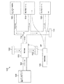
図1は、熱電発電のために多数の位置を識別することができる標準的な航空機ブリード空気システム100を示す。定めるところにより、航空機ブリードシステム100は標準的に、エンジン又はモータ駆動コンプレッサー108、熱交換器110、排気装置112、ブリード空気ダクト114、翼/カウル氷結防止システム116、環境制御システム118、窒素発生システム120、及びブリード空気104を使用しうるその他のシステム122を含むことができる。熱電発電機106を航空機ブリードシステム100内部の様々な箇所及び位置に統合して、例えば非限定的に、熱交換器110、環境制御システム118、及び窒素発生システム120等の電気エネルギーを生成することができる。 熱電発電機106を航空機ブリードシステム100の内部又は外部のその他の箇所に連結させることができ、ここで温度差を維持することができ、これにより電気エネルギーを生成することができる。当業者は、航空機ブリードシステム100がより多い又は少ない構成部品を含むことができ、図1は説明のために提供されていることを理解するだろう。
FIG. 1 shows a standard aircraft bleed
ブリード空気104は、熱電発電機106を介して有用な電気エネルギーに変換させることができる熱エネルギーを含むことができる。図示したように、ブリード空気104はエンジン又はモータ駆動コンプレッサー108から来る場合がある。通常、エンジンはコンプレッサーステージ後、及び燃料がバーナーに注入される前に、ガスタービン内部においてブリード空気104を発生させることができる。ブリード空気104はしばしば高圧及び高温である。
The bleed
熱交換器110はエンジン又はモータ駆動コンプレッサー108からブリード空気104を受け入れることができる。熱交換器110は次に通常ラム空気102を使用してブリード空気104を冷却することができる。図示するように、熱電発電機106を熱交換器110内部に組み込んで、熱交換器110に供給される高温のブリード空気104と低温のラム空気102の利点を生かして、電気エネルギーを生成することができる。
The
通常はしかしながら、ブリード空気ダクト114を使用して航空機ブリードシステム100内部のシステムにブリード空気104を供給することができる。ある実施形態では、ブリード空気104を翼/カウル氷結防止システム116に供給することができる。通常、翼/カウル氷結防止システム116は、最終的に翼又はその他の表面全体の気流を乱す可能性のある飛行表面上に大気氷が堆積しないように設計することができる。
Typically, however,
ブリード空気104を環境制御システム118へ巡回させることもでき、環境制御システム118はブリード空気104を取り込み、乗客のために新鮮な調整空気の形で客室へ送る。ある実施形態において、熱交換器110からのブリード空気104はさらに、環境制御システム118の空調装置を通して冷却される。
The
上述したように、熱電発電機106を環境制御システム118に配置して、電気エネルギーを生成することができる。ブリード空気ダクト114を通って流れるブリード空気104及びラム空気102を使用し、ブリード空気104とラム空気102との間の温度勾配を利用して電気エネルギーを生成することができる。
As described above, the
ブリード空気104をその他のシステム122に供給することもでき、そのうちのいくつかのシステムは熱電発電機106を使用して電気エネルギーを生成することができる。ある実施例において、ブリード空気104を空気圧式アクチュエータにおいて使用することができる。当業者はブリード空気104を使用可能な様々な応用形態が存在し、上述した応用形態は本願の範囲を限定するものではないことを理解するだろう。
Bleed
図示したように、ある実施形態において、ブリード空気104を窒素発生システム120に供給することができる。図2は、一実施形態による空気間熱交換器200付き熱電発電機を有する実例となる窒素発生システム120の標準的な構成部品を表す例示のブロック図である。現在の実施形態では空気間熱交換器に連結された熱電発電機が図示されているが、多数の構成を使用することができる。 例えば、熱電発電機は窒素発生システム120の外にあり、空気間熱交換器から離れていてよい。ある代替例において、熱電発電機106を空気間熱交換器の近くに置かなくてもよいように導管を位置づけすることができる。空気間熱交換器200付き熱電発電機106に関する詳細を下にさらに詳しく説明する。
As shown, in one embodiment, bleed
窒素発生システム120は、ラム空気102とブリード空気104を受け入れて、ラム空気の排気206を放出し、窒素富化空気を燃料タンク208に供給することができる。ラム空気102は概して冷えた又は低温の空気を指し、図2に示す長い線によって表される。ラム空気102はある実施形態において、標準的な暑い日に航空機巡航高度において0℃又は0℃未満で取り込むことができる。後に記載するように、冷えたラム空気102は温度差を起こして、熱電発電機106によって有用な電力を生成するために使用することができる。
ラム空気102は航空機の吸気口を通して受け入れることができる。ある実施形態において、ラム空気はラムスクープから導入することが可能である。 当然ながら、ラム空気102は様々な供給源から取り込むことができ、上述したラム空気吸気口に限定されない。冷えた空気をラム空気102と置換する、又は同じくラム空気102と呼ぶことができる。
The
図示するように、ラム空気102を使用してブリード空気104を冷却し、窒素発生システム120によって空気をろ過して、窒素及び酸素に分けることができる。ブリード空気104はしばしば廃熱の一部を含む。ブリード空気104又は窒素システムに含まれる廃熱を使用した熱電発電により一般にブリード空気104の抽出が増加することはない。
As shown,
図2内の点線で表されたブリード空気104はおおむね、エンジンコンプレッサー又は独立型モータ駆動コンプレッサー108から受け入れた空気である。ラム空気102とブリード空気104を使用して温度差を発生させ、この温度差により熱電発電機106の発電が可能になり得る。
The
多くの実施形態では、窒素発生システム120は航空機の燃料タンク208に接続されている。窒素富化空気には燃料タンクを不活性化する作用があるため、燃料タンク108を好ましくない危険から安定させることができる。
In many embodiments, the
窒素発生システム120内部には、オゾンコンバータ212、空気間熱交換器200付き熱電発電機、及びフィルター/空気分離ステージ214が存在しうる。図2に示すように、オゾンコンバータ212は空気間熱交換器200付き熱電発電機よりも前に、流入ブリード空気104を受け入れることができる。
Within the
オゾンコンバータ212からのブリード空気104は空気間熱交換器200付き熱電発電機に供給することができる。熱電発電機106はラム空気102とブリード空気104との温度差を利用して電気エネルギーを生成することができる。加えて、空気間熱交換器はラム空気102を使用してブリード空気104の温度を冷却する又は低下させる。空気を冷却することによって、この空気を航空機内部のその他のシステムで使用することが可能になる。ある実施形態では、冷却したブリード空気104の温度は85℃である。ブリード空気104を冷却するために使われるラム空気102の一部はラム空気排気口206を通して吐き出されうる。
The
冷却されたブリード空気104は次にフィルター/空気分離ステージ214に送ることができる。フィルター/空気分離ステージ214は冷却されたブリード空気104から窒素及び酸素富化部分を分離させることができる。窒素及び酸素を互いに分離させる当業者に既知の方法は多数ある。窒素富化空気は次に燃料タンク208に送ることができる。
The cooled
幾つかの構成部品を図2に示したが、当業者には、より少ない又は多いパーツを窒素発生システム120内に配置することができることが明らかである。上述した窒素発生システム120は実例の説明のためのものであって、本願の範囲を限定するものと解釈すべきでない。
Although several components are shown in FIG. 2, it will be apparent to those skilled in the art that fewer or more parts can be placed in the
基本的に、窒素発生システム120に統合された熱電発電機106は廃熱を電力に変換することができる。ある実施形態において、熱電発電機はブリード空気によって運ばれる廃熱の約10%の電力を供給することができる。これは熱電装置の効率性によって制限されうる。熱電装置はまた、ブリード空気104を冷却するために使用するラム空気102を減らすことができる。使われるラム空気102の量が少ないと、航空機の空気抵抗もまた低下しうる。
Basically, the
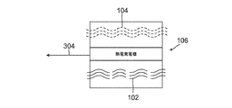
前述の窒素発生システム120では、ブリード空気104が冷却された時に、ブリード空気104によって運ばれる熱含有量はラム空気102の冷却工程を通して処理されている。図3に示すように、熱電発電機106を窒素発生システム120、又は上述したその他のシステムに連結させることによって、熱電発電機106はブリード空気104を利用し、そうでなければ無駄になる熱の利点を生かして発電304することができる。ラム空気102を熱電発電機106の一方の側に、ブリード空気104を他方の側に通すことにより、熱電発電機106によって発電304が行われる。
In the
熱電発電機106は固体の発電装置であってよい。標準的には、発電機106は小型で静かで非常に頑丈なものである。可動パーツがないこと、またその簡易性により、発電機106は維持するのにあまり手間がかからない。さらに、発電機106は航空機電力システムに対して重量、容量、及びコストの節約を提供することができる。
The
一般に、ラム空気102又はブリード空気104のいずれかの気流の方向は熱電発電機106の作動原理に影響を与えない。これは熱電発電機106が単にラム空気102及びブリード空気104との間の温度差を利用して発電304するためである。いくつかの実施形態においてはしかしながら、気流の方向は全体的なエネルギー変換効率に影響を与えうる。図3において指定され、図2と一致するように、ラム空気102は長い線によって表され、ブリード空気104は点線を使用して示されている。
In general, the direction of air flow in either
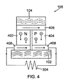
図示目的で、そして本明細書に記載の本願を限定することなく、図4に、熱電発電機106の一実施形態を示す。発電機106はある物質の対向面の間の温度差の利点を生かす。物質の一方の面406を比較的高温に暴露することができ、その一方で反対の面408を比較的低温に暴露することができる。電圧量304は通常、ブリード空気104とラム空気102との温度差に依存する。多くの熱電発電機106は温度差を調整することができないが、窒素発生システム120内の熱電発電機106によって供給される電圧304は、ラム空気102とブリード空気104がしばしば一貫した温度で受け入れられるため、一貫した電圧を供給することが可能である。一般に電圧304は温度差が閾値を超えるときに発生する。
For illustration purposes and without limiting the application described herein, FIG. 4 illustrates one embodiment of a
図4に示すように、熱電発電機106はn型要素402とp型要素404を含むことができる。電荷は、ブリード空気104が適用された時に、n型要素402を通ってp型要素404に流れることができる。一般に、n型要素402の電子は電流とは反対の方向に移動することができ、p型要素404の正孔は電流の方向に移動することができ、いずれにおいても熱電発電機106の一方の側面406から他方の側面408へ熱が除去される。熱源によりn型要素402の電子がより低温の領域に向かって追いやられるため、熱電発電機106を通る電流が発生する。p型要素404の正孔は次に電流の方向に流れることができる。電流はその後負荷に電力を供給するために使用することができ、これにより熱エネルギーが電気エネルギー304に変換される。熱電発電機106の両方の端部406及び408が一定の温度差に保たれる時に、所定の負荷条件において一定の電力の流れがある。ブリード空気から熱を除去して電気エネルギー204を生成することで、ブリード空気104を冷却するのに使用するラム空気102の量を減らすことができる。
As shown in FIG. 4, the
上述した熱電発電機106は一つの実例となる実施形態であり、範囲を限定するものとみなすべきではない。当業者には、温度差を利用して発電304できる多数の異なる種類の熱電発電機106が明らかである。さらに、ブリード空気104とラム空気102を入れ替えて対向端部に流して電気エネルギー204を生成することができる。例えば、空気102を端部406全体に流すことができ、その一方でブリード空気104を端部408全体に流すことができる。
The
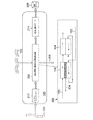
ここで図5を参照すると、空気間熱交換器200付き熱電発電機が一実施形態による窒素発生システム120に統合される。点線526で示すように、空気間熱交換器200付き熱電発電機を、既存の窒素発生システム120、又は上述したすべてのシステムに配置することができる。システム制御502は通常、空気間熱交換器200付き熱電発電機を組み込むためにわずかに変更する必要があるか、まったく変更する必要がない。
Referring now to FIG. 5, a thermoelectric generator with an
システム制御502により、いくつかの制御ラインを介してコントローラを維持し管理することができる。ある実施形態では、コントローラの電源の入切をすることができる。あるいは、コントローラを特定のレベルまで電源をオンにする又はオフにすることができる。例えば、コントローラは90%の気流の通過を許可することができる。システム制御502はある実施形態によれば、ライン504を介してラム空気コントローラ506に連結させることができる。ブリード空気制御バルブ510はライン508を介してシステム制御502に接続することができ、ライン512を介してバイパス流量バルブ514をシステム制御502に接続することができる。
作動中に、所定量のラム空気102とブリード空気104を窒素発生システム120に供給することができる。制御ライン504を使用することにより、システム制御502はコントローラ506を介してシステム120に供給されるラム空気102の量を増やす、又は減らすことができる。図示したように、ラム空気102は空気間熱交換器200付き熱電発電機に直接供給することができる、あるいは空気間熱交換器200付き熱電発電機へ供給される前にろ過することができる。ラム空気102はその後ラム空気排気口206を通して放出することができる。上述したように、ラム空気の吸気量が大きいほど、航空機内部に通常発生する抵抗がより高くなる。
During operation, a predetermined amount of
加えて、システム制御502は制御ライン508を使用して、制御バルブ510を介してシステム120に供給されるブリード空気104の量を増やす又は減らすことができる。通常、ブリード空気104はエンジン又はモータ駆動コンプレッサー108から入りうる。ブリード空気104は次に、図5に示すようにオゾンコンバータ512へ供給されうる。
In addition,
ブリード空気104がまだ高温であるうちに、オゾンコンバータ212によりブリード空気104内のオゾンレベルを低減させることができる。ブリード空気104は、空気間熱交換器200付き熱電発電機を通過させることができる、又は空気間熱交換器200付き熱電発電機を完全に迂回させることができ、これはバイパス流量バルブ514と制御ライン512によって決まる。空気間熱交換器200付き熱電発電機を迂回することができるか否かを決定するために、システム制御502は温度監視ライン516を含むことができる。通常、ブリード空気104が分離するのに十分冷却されていると、空気間熱交換器200付き熱電発電機は、バイパス流量バルブ514と制御ライン512を使用して迂回することができる。あるいは、ブリード空気104が十分冷却されていない場合、バイパス流量バルブ514によってブリード空気104の流れが阻止され、この結果、ブリード空気104は空気間熱交換器200付き熱電発電機を通って流れることができる。要するに、バイパス流量バルブ514は、フィルター/空気分離ステージ214へ供給されるブリード空気104の温度を監視及び制御することができる。
While the
バイパス流量バルブ514を制御ライン512とともに使用してブリード空気104の温度を監視することができるが、当業者はフィルター/空気分離ステージ214に正確な温度を有するブリード空気104を確実に供給する多数の方法があることを理解するだろう。ある実施形態においては、システム制御502により、制御ライン508を使用してブリード空気制御バルブ510を通ってくるブリード空気104の量を減らす又は増やすことができる。あるいは、ライン504を介してラム空気コントローラ506によってラム空気102の量を調整することができる。
Although the
ブリード空気104が冷却された後に、ブリード空気104をフィルター/空気分離ステージ214へ供給することができ、ここでブリード空気104を酸素富化空気522と窒素富化空気524に分離することができる。酸素富化空気522を排気106として供給することができると同時に、窒素富化空気524を燃料タンク208に送ることができ、前述したように酸素、燃料蒸気、及び点火源の可燃性結合を除去することができる。
After the
通常の実施形態においては、システム制御502は表示装置518を介してシステムのステータスを図示することができる。システム制御502はまた、外部制御520を通して管理及び操作することも可能である。システム制御502は全体的にハードウェアの実施形態、全体的にソフトウェアの実施形態、又はハードウェア及びソフトウェア要素を両方含む実施形態の形態であってよい。ある実施形態は、システム制御502は例えばファームウェア、常駐ソフトウェア、及びマイクロコード等の形態を非限定的に含むソフトウェアにおいて実行される。ハードウェアは処理装置、システムメモリ、及び様々なシステム・コンポーネントを作動可能に連結させるシステムバスを含むことができる。
In a typical embodiment,
以前に、空気間熱交換器200付き熱電発電機は単一ユニットとして説明した。図6は別の実施形態による、熱電発電機106と空気間熱交換器604を分割するシステムアーキテクチャを示すブロック図を提供する。窒素発生システム120はラム空気102とブリード空気104を受け入れて、ラム空気の排気206を放出し、窒素富化空気を燃料タンク208に供給することができる。
Previously, the thermoelectric generator with air-to-
図示するように、空気間熱交換器200付き熱電発電機が拡大されている。拡大区域の下部に図示されるラム空気102は最初に熱電発電機106を通り、その後逆流空気間熱交換器604を通って流れることができる。拡大区域の最上部に描かれるブリード空気104は最初に熱電発電機106へ供給されうる。その後、ブリード空気104は空気間熱交換器604に供給されうる。
As illustrated, the thermoelectric generator with the air-to-
通常、ラム空気102とブリード空気104の相対的な気流方向の結果、流れ方向において異なる温度差を生じるため、発電304も異なる可能性がある。ラム空気102を使用して、ブリード空気104をフィルター/空気分離ステージ114に好適な温度にまで冷却することができ、これにより窒素発生システム110が空気を窒素と酸素富化部分に分離する。
Typically, the
図6Aは、一実施形態による窒素発生システム120へのラム空気102とブリード空気104の例示の流れの統合を示す図である。図示したように、コントローラと制御ラインは上述したものと同様のものである。 実例において、ブリード空気102は最初に熱電発電機106に供給され、その後で空気間熱交換器604を通ることができる。ラム空気104は最初に熱電発電機106を通り、その後逆流空気間熱交換器604を通って流れることができる。ブリード空気104とラム空気102の温度差の結果、熱電発電機106によって発電を行うことができる。熱電発電機106によってブリード空気104内の熱がいくらか下がるため、ブリード空気104を冷却するためのラム空気102の量を減らすことができる。
FIG. 6A is a diagram illustrating exemplary flow integration of
図6及び6Aは、ラム空気102とブリード空気104を最初に熱電発電機106に供給し、その後空気間熱交換器604に供給する実例となる流れを示す。当業者には、窒素発生システム120内にラム空気102及びブリード空気104を流す多数の異なる方法が存在する可能性があることが明らかである。
FIGS. 6 and 6A illustrate an example flow in which
図7は、一実施形態によるブリード空気104及びラム空気102を流す代替方法のシステムアーキテクチャを示すブロック図を提供する。一般に、窒素発生システム120はラム空気102及びブリード空気104を受け入れて、ラム空気の排気206を放出し、窒素富化空気を燃料タンク208へ供給することができる。空気間熱交換器200付き熱電発電機を拡大して図示する。拡大区域の下部に図示されるラム空気102は最初に熱電発電機106の後部を通り、その後空気間熱交換器604の後部を通って流れることができる。
FIG. 7 provides a block diagram illustrating a system architecture of an alternative method of flowing
加えて、拡大部分の最上部に描かれているブリード空気104を最初に熱電発電機106へ供給することができる。その後で、ブリード空気104を空気間熱交換器604へ供給することができる。熱電発電機106は電気エネルギー304を生成することができ、空気間熱交換器604はフィルター/空気分離ステージ214のためにブリード空気104を冷却することができ、これにより窒素発生システム120は空気を窒素及び酸素富化部分に分離する。
In addition, the
図7Aは一実施形態による窒素発生システム120への代替例の流れの統合を示す図である。図面において、ブリード空気104を最初に熱電発電機106へ供給し、その後空気間熱交換器604へと供給することができる。ラム空気104は最初に熱電発電機106の後部を通り、その後空気間熱交換器604の後部を通って流れることができる。ブリード空気104とラム空気102の温度差の結果として、熱電発電機106が発電304する。熱電発電機106によりブリード空気104内の熱がいくらか下がるため、ブリード空気104を冷却するラム空気102の量を減らすことができる。
FIG. 7A is a diagram illustrating alternative flow integration into the
ラム空気102とブリード空気104の流れの2つの実施例を図示したが、当業者には気流の流れの多数の構成が明らかである。さらに、前述したように、空気間熱変換器604と熱電発電機106を分離しなくてもよく、その代わりに同じ構造内に組み込むことができる。
While two examples of
図8A及び8Bは熱電発電機106の一実施形態である。図8Aに示すように、熱電発電機106は内側チューブ804と外側チューブ806と、これらのチューブの間の熱電素子802を含むことができる。熱電発電機106は、一方の端部を通してラム空気102を、他方を通してブリード空気104を受け入れることができる。熱電発電機106は、温度差を利用して発電304することができる。
8A and 8B are one embodiment of a
図8Bは一実施形態による熱電発電機106の断面側面図である。図示したように、ラム空気102は外側チューブ806を通して送ることができ、ブリード空気104は内側チューブ804を通して送ることができる。外側チューブ806と内側チューブ804の間に発電304する熱電素子802があってよい。ラム空気102は外側チューブ806を通して、またブリード空気104は内側チューブ804内部で供給することができるが、これらは置換えが可能である。さらに、気流は上述の流れに応じて切替することができる。
FIG. 8B is a cross-sectional side view of a
図9Aは別の熱電発電機106の断面側面図である。図示したように、熱電発電機106は一端部902と第2端部904を有していてよい。各端部は熱電素子802によって分離されていてよい。図9Bに示すように、ブリード空気104は端部902の上を通ることができ、ラム空気は端部904の上を通ることができ、これにより熱電素子802が発電304することができる。各熱電発電機106は、非限定的に図1に示すシステムを含む上述の全てのシステム内に配設することができる。
FIG. 9A is a cross-sectional side view of another
本開示の実施形態を様々な特定の実施形態の観点から説明してきたが、当業者には本開示の実施形態を、請求項の精神及び範囲内の変更を行って実施することが可能であることが明らかである。
また、本発明は以下に記載する態様を含む。
(態様1)
発電装置であって、ブリード空気システム(100)と、前記ブリード空気システム(100)に連結され、ラム空気とブリード空気との間の温度差を利用して前記発電する熱電発電機(106)を備える発電装置。
(態様2)
前記ブリード空気システム(100)は、前記ブリード空気内のオゾンレベルを低減するオゾンコンバータ(212)と、前記オゾンコンバータ(212)から前記ラム空気と前記ブリード空気を受け入れる空気間熱交換器(200)を備える、態様1に記載の装置。
(態様3)
前記熱電発電機(106)が空気間熱交換器(200)に連結されている、態様1又は2に記載の装置。
(態様4)
前記ブリード空気システム(100)が、前記ラム空気と前記ブリード空気を監視し管理するシステム制御を含む、態様1乃至3のいずれか1項に記載の装置。
(態様5)
空気間熱交換器(200)が、前記ラム空気を使用して前記ブリード空気を冷却する、態様1乃至4のいずれか1項に記載の装置。
(態様6)
前記熱電発電機(106)に連結された窒素発生システム(120)をさらに備える、態様1乃至5のいずれか1項に記載の装置。
(態様7)
航空機ブリードシステム上で発電する方法であって、ラム空気を受入れ、ブリード空気を受け入れ、前記ラム空気及び前記ブリード空気を前記航空機ブリードシステムに連結された熱電発電機(106)に通して発電するステップを含む方法。
(態様8)
前記熱電発電機(106)によって前記ブリード空気を冷却して、前記航空機ブリードシステムによって使用されるラム空気の量を減らすステップをさらに含む、態様7に記載の方法。
(態様9)
前記熱電発電機(106)によって前記ブリード空気を冷却して、前記航空機ブリードシステムによって使用されるラム空気の量を減らすステップをさらに含む、態様7又は8に記載の方法。
While embodiments of the present disclosure have been described in terms of various specific embodiments, those skilled in the art can implement the embodiments of the present disclosure with modification within the spirit and scope of the claims. It is clear.
Moreover, this invention includes the aspect described below.
(Aspect 1)
A bleed air system (100) and a thermoelectric generator (106) connected to the bleed air system (100) and generating the power using a temperature difference between ram air and bleed air. A power generator provided.
(Aspect 2)
The bleed air system (100) includes an ozone converter (212) that reduces the ozone level in the bleed air, and an air heat exchanger (200) that receives the ram air and the bleed air from the ozone converter (212). An apparatus according to aspect 1, comprising:
(Aspect 3)
The apparatus according to aspect 1 or 2, wherein the thermoelectric generator (106) is connected to an air-to-air heat exchanger (200).
(Aspect 4)
Apparatus according to any one of aspects 1 to 3, wherein the bleed air system (100) includes system controls for monitoring and managing the ram air and the bleed air.
(Aspect 5)
The apparatus of any one of aspects 1 to 4, wherein an air to air heat exchanger (200) uses the ram air to cool the bleed air.
(Aspect 6)
The apparatus of any one of aspects 1 to 5, further comprising a nitrogen generation system (120) coupled to the thermoelectric generator (106).
(Aspect 7)
A method of generating electricity on an aircraft bleed system, comprising: receiving ram air; receiving bleed air; and passing the ram air and the bleed air through a thermoelectric generator (106) coupled to the aircraft bleed system. Including methods.
(Aspect 8)
The method of aspect 7, further comprising cooling the bleed air by the thermoelectric generator (106) to reduce the amount of ram air used by the aircraft bleed system.
(Aspect 9)
The method of aspect 7 or 8, further comprising cooling the bleed air by the thermoelectric generator (106) to reduce the amount of ram air used by the aircraft bleed system.
Claims (7)
前記ブリード空気システムに連結され、ラム空気とブリード空気との間の温度差を利用して発電する熱電発電機と、を備えるシステム。 A bleed air system that uses ram air to cool the bleed air; and
A thermoelectric generator connected to the bleed air system and generating power using a temperature difference between the ram air and the bleed air.
ラム空気を受入れるステップと、
ブリード空気を受け入れるステップと、
航空機ブリードシステムにおいて、ラム空気を使用してブリード空気を冷却するステップと、
前記ラム空気及び前記ブリード空気を前記航空機ブリードシステムに連結された熱電発電機に通してラム空気とブリード空気との間の温度差を利用して発電するステップと、を含む方法。 A method of cooling bleed air,
Accepting ram air,
Receiving the bleed air; and
In an aircraft bleed system, cooling the bleed air using ram air;
Generating the ram air and the bleed air through a thermoelectric generator coupled to the aircraft bleed system utilizing a temperature difference between the ram air and the bleed air.
Applications Claiming Priority (3)
| Application Number | Priority Date | Filing Date | Title |
|---|---|---|---|
| US12/632,250 US8484983B2 (en) | 2009-12-07 | 2009-12-07 | Thermoelectric generator on an aircraft bleed system |
| US12/632,250 | 2009-12-07 | ||
| PCT/US2010/053622 WO2011071602A2 (en) | 2009-12-07 | 2010-10-21 | Thermoelectric generator on an aircraft bleed system |
Publications (3)
| Publication Number | Publication Date |
|---|---|
| JP2013512821A JP2013512821A (en) | 2013-04-18 |
| JP2013512821A5 JP2013512821A5 (en) | 2013-11-07 |
| JP5965320B2 true JP5965320B2 (en) | 2016-08-03 |
Family
ID=44063309
Family Applications (1)
| Application Number | Title | Priority Date | Filing Date |
|---|---|---|---|
| JP2012542013A Active JP5965320B2 (en) | 2009-12-07 | 2010-10-21 | Thermoelectric generator for aircraft bleed system |
Country Status (6)
| Country | Link |
|---|---|
| US (1) | US8484983B2 (en) |
| EP (1) | EP2509869B1 (en) |
| JP (1) | JP5965320B2 (en) |
| CN (1) | CN102648127B (en) |
| CA (1) | CA2782972C (en) |
| WO (1) | WO2011071602A2 (en) |
Families Citing this family (37)
| Publication number | Priority date | Publication date | Assignee | Title |
|---|---|---|---|---|
| EP2500269A1 (en) * | 2011-03-18 | 2012-09-19 | AGUSTAWESTLAND S.p.A. | Aircraft capable of hovering |
| US9470153B2 (en) * | 2011-10-05 | 2016-10-18 | United Technologies Corporation | Combined pump system for engine TMS AOC reduction and ECS loss elimination |
| GB2496839A (en) * | 2011-10-24 | 2013-05-29 | Ge Aviat Systems Ltd | Thermal electrical power generation for aircraft |
| US9388740B2 (en) * | 2012-02-15 | 2016-07-12 | The Boeing Company | Thermoelectric generator in turbine engine nozzles |
| US8944367B2 (en) * | 2012-03-05 | 2015-02-03 | Sikorsky Aircraft Corporation | Rotary wing aircraft propulsion system |
| US9394803B2 (en) * | 2012-03-14 | 2016-07-19 | United Technologies Corporation | Bypass air-pump system within the core engine to provide air for an environmental control system in a gas turbine engine |
| US9163562B2 (en) * | 2012-03-14 | 2015-10-20 | United Technologies Corporation | Constant speed pump system for engine ECS loss elimination |
| US9151224B2 (en) * | 2012-03-14 | 2015-10-06 | United Technologies Corporation | Constant-speed pump system for engine thermal management system AOC reduction and environmental control system loss elimination |
| US9360240B2 (en) | 2012-11-09 | 2016-06-07 | Laird Technologies, Inc. | Thermoelectric assembly |
| CN104870312B (en) * | 2012-12-28 | 2019-06-18 | 通用电气公司 | The system and method generated for aviation electrical power |
| GB2513132B (en) * | 2013-04-16 | 2015-05-27 | Ge Aviat Systems Ltd | Method for predicting a bleed air system fault |
| US20140352324A1 (en) * | 2013-05-29 | 2014-12-04 | Hamilton Sunstrand Corporation | Dual pressure regulator shut off valve apparatus |
| EP2829706B1 (en) * | 2013-07-25 | 2016-09-14 | The Boeing Company | Bleed air systems for use with aircrafts and related methods |
| US9666781B2 (en) * | 2013-08-19 | 2017-05-30 | The Boeing Company | Methods for recovering waste energy from bleed air ducts |
| CN106471220B (en) | 2014-07-03 | 2019-07-23 | 通用电气公司 | Jet engine cold air cooling system |
| GB201415078D0 (en) | 2014-08-26 | 2014-10-08 | Rolls Royce Plc | Gas turbine engine anti-icing system |
| EP2995553B1 (en) * | 2014-09-09 | 2017-02-01 | Airbus Defence and Space GmbH | Air generation unit for an aircraft and method for its operation |
| US9901874B2 (en) | 2015-01-20 | 2018-02-27 | Hamilton Sundstrand Corporation | High temperature air separation system architecture |
| EP3069997B1 (en) * | 2015-03-16 | 2020-04-29 | Airbus Operations S.L. | Aircraft comprising a heat exchanger |
| US10144521B2 (en) * | 2015-08-04 | 2018-12-04 | Hamilton Sundstrand Corporation | Electric compressor for use with a wing anti-ice system |
| US10082059B2 (en) * | 2015-09-17 | 2018-09-25 | Borla Performance Industries, Inc. | Recovery of electrical energy and water from exhaust gas |
| US20170159563A1 (en) * | 2015-12-07 | 2017-06-08 | General Electric Company | Method and system for pre-cooler exhaust energy recovery |
| US10801408B2 (en) * | 2016-02-03 | 2020-10-13 | Rolls-Royce North American Technologies Inc. | Gas turbine engine with thermoelectric system |
| US20170268430A1 (en) * | 2016-03-15 | 2017-09-21 | Hamilton Sundstrand Corporation | Engine bleed system with turbo-compressor |
| US11473497B2 (en) | 2016-03-15 | 2022-10-18 | Hamilton Sundstrand Corporation | Engine bleed system with motorized compressor |
| US10794295B2 (en) * | 2016-03-15 | 2020-10-06 | Hamilton Sunstrand Corporation | Engine bleed system with multi-tap bleed array |
| CN106089438A (en) * | 2016-06-16 | 2016-11-09 | 电子科技大学 | A kind of miniature temperature difference electricity generation device and the application process on put-put energy regenerating thereof |
| WO2018002855A1 (en) * | 2016-06-30 | 2018-01-04 | Bombardier Inc. | Assembly and method for conditioning engine-heated air onboard an aircraft |
| US10919637B2 (en) * | 2016-07-12 | 2021-02-16 | Hamilton Sunstrand Corporation | Temperature control system for fuel tank inerting system |
| US10267334B2 (en) * | 2016-08-01 | 2019-04-23 | United Technologies Corporation | Annular heatshield |
| US10931170B2 (en) | 2017-05-10 | 2021-02-23 | Hamilton Sundstrand Corporation | Motor cooling utilizing cabin air |
| US10711693B2 (en) | 2017-07-12 | 2020-07-14 | General Electric Company | Gas turbine engine with an engine rotor element turning device |
| CN108045587B (en) * | 2017-12-26 | 2023-07-11 | 南京航空航天大学 | Waste heat recovery system of oxygen consumption type inerting fuel tank based on thermoelectric generation technology |
| CN108843460A (en) * | 2018-06-28 | 2018-11-20 | 厦门大学 | Heat to electricity conversion and pushing method is pre-chilled in turbo ramjet engine |
| CN114435597A (en) * | 2022-01-25 | 2022-05-06 | 山东大学 | Temperature difference power generation device for wing anti-icing and deicing assembly, anti-icing and deicing assembly and method |
| EP4276017A1 (en) * | 2022-05-10 | 2023-11-15 | Airbus SAS | Fluid transport device and method for manufacturing a fluid transport device |
| CN117360779B (en) * | 2023-12-08 | 2024-02-23 | 中国航空工业集团公司金城南京机电液压工程研究中心 | Electric heating complementary system with fuel oil as power source and heat sink |
Family Cites Families (15)
| Publication number | Priority date | Publication date | Assignee | Title |
|---|---|---|---|---|
| US4819425A (en) * | 1982-03-18 | 1989-04-11 | The Boeing Company | Primary-secondary ventilated flow mixer nozzle for high bypass turbo fan jet propulsion system |
| US6100463A (en) * | 1997-11-18 | 2000-08-08 | The Boeing Company | Method for making advanced thermoelectric devices |
| JP2001071999A (en) * | 1999-09-06 | 2001-03-21 | Shimadzu Corp | Air conditioning unit for aircraft |
| JP2002130860A (en) * | 2000-10-18 | 2002-05-09 | Shimadzu Corp | Air conditioner |
| US6782701B2 (en) | 2003-01-22 | 2004-08-31 | Honeywell International Inc. | Master-slave engine bleed flow sharing control method and system |
| US20050022855A1 (en) | 2003-07-30 | 2005-02-03 | Raver Bernard J. | Thermoelectric power generator for a gas turbine engine |
| US7152635B2 (en) * | 2004-02-10 | 2006-12-26 | The Boeing Company | Commercial aircraft on-board inerting system |
| US7013636B2 (en) * | 2004-04-22 | 2006-03-21 | The Boeing Company | System and method for controlling the temperature and infrared signature of an engine |
| DE102004038860A1 (en) * | 2004-08-10 | 2006-02-23 | Airbus Deutschland Gmbh | Process air production system for aircraft has existing cooling system whose heat exchanger is arranged in ram-air cooling channel serving as cooling sink |
| WO2007098847A1 (en) * | 2006-02-28 | 2007-09-07 | Bayerische Motoren Werke Aktiengesellschaft | Motor vehicle comprising a unit operated by cryogenically stored fuel |
| US20100021360A1 (en) | 2006-09-08 | 2010-01-28 | Parker Filtration & Separation B.V. | Use of ozone conversion in aircraft air management |
| DE102007019820B4 (en) * | 2007-04-26 | 2012-03-08 | Airbus Operations Gmbh | Cooling system through boundary layer extraction |
| US8127555B2 (en) | 2007-12-13 | 2012-03-06 | Pratt & Whitney Rocketdyne, Inc. | Flowpath heat exchanger for thermal management and power generation within a hypersonic vehicle |
| US9018512B2 (en) | 2007-12-21 | 2015-04-28 | The Boeing Company | Thermoelectric generation system |
| US20100011781A1 (en) | 2008-07-21 | 2010-01-21 | Lents Charles E | Heat exchanger assembly for an aircraft control |
-
2009
- 2009-12-07 US US12/632,250 patent/US8484983B2/en active Active
-
2010
- 2010-10-21 CA CA2782972A patent/CA2782972C/en active Active
- 2010-10-21 JP JP2012542013A patent/JP5965320B2/en active Active
- 2010-10-21 WO PCT/US2010/053622 patent/WO2011071602A2/en active Application Filing
- 2010-10-21 EP EP10771858.7A patent/EP2509869B1/en active Active
- 2010-10-21 CN CN201080055524.0A patent/CN102648127B/en active Active
Also Published As
| Publication number | Publication date |
|---|---|
| US8484983B2 (en) | 2013-07-16 |
| WO2011071602A3 (en) | 2011-08-18 |
| CA2782972A1 (en) | 2011-06-16 |
| CA2782972C (en) | 2017-11-21 |
| CN102648127B (en) | 2015-09-30 |
| EP2509869B1 (en) | 2016-08-24 |
| WO2011071602A2 (en) | 2011-06-16 |
| CN102648127A (en) | 2012-08-22 |
| EP2509869A2 (en) | 2012-10-17 |
| US20110131999A1 (en) | 2011-06-09 |
| JP2013512821A (en) | 2013-04-18 |
Similar Documents
| Publication | Publication Date | Title |
|---|---|---|
| JP5965320B2 (en) | Thermoelectric generator for aircraft bleed system | |
| US11466904B2 (en) | Environmental control system utilizing cabin air to drive a power turbine of an air cycle machine and utilizing multiple mix points for recirculation air in accordance with pressure mode | |
| CN105620756B (en) | Environmental control system using cabin air to drive power turbine of air cycle machine | |
| US7412840B2 (en) | Aircraft ground support cart with component life optimization control | |
| JP6412010B2 (en) | Air conditioning method and system for aircraft | |
| CN106240827B (en) | Recirculation system for parallel ram heat exchanger | |
| US11254435B2 (en) | Supplemental pack driven by bleed air and cabin air | |
| JP2011504844A (en) | Air conditioning system with mixed bleed air operation | |
| EP3085622B1 (en) | Environmental control system mixing cabin discharge air with bleed air during a cycle | |
| US10293946B2 (en) | Hybrid electric | |
| US20180002037A1 (en) | Integrated mobile ground support system for servicing aircraft | |
| US10507928B2 (en) | High efficiency electrically driven environmental control system | |
| US11085673B2 (en) | Advanced environmental control system in an integrated simple cycle pack | |
| EP4265521A1 (en) | Environmental control system with air powered pump | |
| JP4144414B2 (en) | Air conditioning system for aircraft | |
| EP3235730B1 (en) | Environmental control system utilizing cabin air to drive a power turbine of an air cycle machine and utilizing multiple mix points for recirculation air in accordance with pressure mode | |
| JP4144379B2 (en) | Air conditioning system for aircraft | |
| JP2004142501A (en) | Air conditioner for aircraft | |
| US20140190190A1 (en) | Aircraft Air Conditioning System and Method of Operating an Aircraft Air Conditioning System | |
| US20170283074A1 (en) | Aircraft air conditioning system including a thermoelectric device |
Legal Events
| Date | Code | Title | Description |
|---|---|---|---|
| A521 | Request for written amendment filed |
Free format text: JAPANESE INTERMEDIATE CODE: A523 Effective date: 20130913 |
|
| A621 | Written request for application examination |
Free format text: JAPANESE INTERMEDIATE CODE: A621 Effective date: 20130913 |
|
| A977 | Report on retrieval |
Free format text: JAPANESE INTERMEDIATE CODE: A971007 Effective date: 20140828 |
|
| A131 | Notification of reasons for refusal |
Free format text: JAPANESE INTERMEDIATE CODE: A131 Effective date: 20140902 |
|
| A521 | Request for written amendment filed |
Free format text: JAPANESE INTERMEDIATE CODE: A523 Effective date: 20141128 |
|
| A02 | Decision of refusal |
Free format text: JAPANESE INTERMEDIATE CODE: A02 Effective date: 20150428 |
|
| A521 | Request for written amendment filed |
Free format text: JAPANESE INTERMEDIATE CODE: A523 Effective date: 20150724 |
|
| A911 | Transfer to examiner for re-examination before appeal (zenchi) |
Free format text: JAPANESE INTERMEDIATE CODE: A911 Effective date: 20150803 |
|
| A912 | Re-examination (zenchi) completed and case transferred to appeal board |
Free format text: JAPANESE INTERMEDIATE CODE: A912 Effective date: 20150814 |
|
| A521 | Request for written amendment filed |
Free format text: JAPANESE INTERMEDIATE CODE: A523 Effective date: 20160510 |
|
| A61 | First payment of annual fees (during grant procedure) |
Free format text: JAPANESE INTERMEDIATE CODE: A61 Effective date: 20160701 |
|
| R150 | Certificate of patent or registration of utility model |
Ref document number: 5965320 Country of ref document: JP Free format text: JAPANESE INTERMEDIATE CODE: R150 |
|
| R250 | Receipt of annual fees |
Free format text: JAPANESE INTERMEDIATE CODE: R250 |
|
| R250 | Receipt of annual fees |
Free format text: JAPANESE INTERMEDIATE CODE: R250 |
|
| R250 | Receipt of annual fees |
Free format text: JAPANESE INTERMEDIATE CODE: R250 |
|
| R250 | Receipt of annual fees |
Free format text: JAPANESE INTERMEDIATE CODE: R250 |
|
| R250 | Receipt of annual fees |
Free format text: JAPANESE INTERMEDIATE CODE: R250 |