JP5965132B2 - Turbine component with cooling features and method of manufacturing the same - Google Patents
Turbine component with cooling features and method of manufacturing the same Download PDFInfo
- Publication number
- JP5965132B2 JP5965132B2 JP2011251175A JP2011251175A JP5965132B2 JP 5965132 B2 JP5965132 B2 JP 5965132B2 JP 2011251175 A JP2011251175 A JP 2011251175A JP 2011251175 A JP2011251175 A JP 2011251175A JP 5965132 B2 JP5965132 B2 JP 5965132B2
- Authority
- JP
- Japan
- Prior art keywords
- channel
- coating
- channels
- metal
- holes
- Prior art date
- Legal status (The legal status is an assumption and is not a legal conclusion. Google has not performed a legal analysis and makes no representation as to the accuracy of the status listed.)
- Active
Links
- 238000004519 manufacturing process Methods 0.000 title claims description 8
- 238000001816 cooling Methods 0.000 title description 43
- 238000000576 coating method Methods 0.000 claims description 79
- 239000011248 coating agent Substances 0.000 claims description 67
- 239000000463 material Substances 0.000 claims description 55
- 238000000034 method Methods 0.000 claims description 43
- 229910052751 metal Inorganic materials 0.000 claims description 31
- 239000002184 metal Substances 0.000 claims description 31
- 229910001092 metal group alloy Inorganic materials 0.000 claims description 22
- 239000000945 filler Substances 0.000 claims description 20
- 239000000446 fuel Substances 0.000 claims description 15
- PXHVJJICTQNCMI-UHFFFAOYSA-N Nickel Chemical compound [Ni] PXHVJJICTQNCMI-UHFFFAOYSA-N 0.000 claims description 14
- 238000000151 deposition Methods 0.000 claims description 14
- 230000008569 process Effects 0.000 claims description 14
- 230000008021 deposition Effects 0.000 claims description 11
- 238000003754 machining Methods 0.000 claims description 8
- 230000003647 oxidation Effects 0.000 claims description 8
- 238000007254 oxidation reaction Methods 0.000 claims description 8
- 229910052750 molybdenum Inorganic materials 0.000 claims description 7
- 239000000843 powder Substances 0.000 claims description 7
- 238000009760 electrical discharge machining Methods 0.000 claims description 5
- 229910052759 nickel Inorganic materials 0.000 claims description 5
- 229910052721 tungsten Inorganic materials 0.000 claims description 5
- 238000011049 filling Methods 0.000 claims description 4
- 238000002844 melting Methods 0.000 claims description 4
- 230000008018 melting Effects 0.000 claims description 4
- RYGMFSIKBFXOCR-UHFFFAOYSA-N Copper Chemical compound [Cu] RYGMFSIKBFXOCR-UHFFFAOYSA-N 0.000 claims description 3
- ZOKXTWBITQBERF-UHFFFAOYSA-N Molybdenum Chemical compound [Mo] ZOKXTWBITQBERF-UHFFFAOYSA-N 0.000 claims description 3
- 229910052782 aluminium Inorganic materials 0.000 claims description 3
- 229910052802 copper Inorganic materials 0.000 claims description 3
- 239000010949 copper Substances 0.000 claims description 3
- 238000005530 etching Methods 0.000 claims description 3
- 239000007788 liquid Substances 0.000 claims description 3
- 239000011733 molybdenum Substances 0.000 claims description 3
- 238000005507 spraying Methods 0.000 claims description 3
- WFKWXMTUELFFGS-UHFFFAOYSA-N tungsten Chemical compound [W] WFKWXMTUELFFGS-UHFFFAOYSA-N 0.000 claims description 3
- 239000010937 tungsten Substances 0.000 claims description 3
- 229910000792 Monel Inorganic materials 0.000 claims description 2
- XAGFODPZIPBFFR-UHFFFAOYSA-N aluminium Chemical compound [Al] XAGFODPZIPBFFR-UHFFFAOYSA-N 0.000 claims description 2
- 238000002386 leaching Methods 0.000 claims description 2
- 238000003801 milling Methods 0.000 claims description 2
- 229910001120 nichrome Inorganic materials 0.000 claims description 2
- 230000001590 oxidative effect Effects 0.000 claims description 2
- 229910000531 Co alloy Inorganic materials 0.000 claims 1
- 229910000990 Ni alloy Inorganic materials 0.000 claims 1
- QVGXLLKOCUKJST-UHFFFAOYSA-N atomic oxygen Chemical compound [O] QVGXLLKOCUKJST-UHFFFAOYSA-N 0.000 claims 1
- 238000010288 cold spraying Methods 0.000 claims 1
- 229910052760 oxygen Inorganic materials 0.000 claims 1
- 239000001301 oxygen Substances 0.000 claims 1
- 238000007750 plasma spraying Methods 0.000 claims 1
- 239000007789 gas Substances 0.000 description 66
- 239000000758 substrate Substances 0.000 description 40
- 239000010955 niobium Substances 0.000 description 37
- 229910052758 niobium Inorganic materials 0.000 description 36
- 239000012071 phase Substances 0.000 description 34
- GUCVJGMIXFAOAE-UHFFFAOYSA-N niobium atom Chemical compound [Nb] GUCVJGMIXFAOAE-UHFFFAOYSA-N 0.000 description 29
- 239000000956 alloy Substances 0.000 description 23
- 229910045601 alloy Inorganic materials 0.000 description 19
- 239000010410 layer Substances 0.000 description 17
- 239000002826 coolant Substances 0.000 description 16
- 239000007787 solid Substances 0.000 description 14
- 239000002131 composite material Substances 0.000 description 12
- 229910000601 superalloy Inorganic materials 0.000 description 12
- 229910052719 titanium Inorganic materials 0.000 description 12
- 239000010936 titanium Substances 0.000 description 12
- 239000012809 cooling fluid Substances 0.000 description 8
- 229910052735 hafnium Inorganic materials 0.000 description 8
- 229910000943 NiAl Inorganic materials 0.000 description 7
- NPXOKRUENSOPAO-UHFFFAOYSA-N Raney nickel Chemical compound [Al].[Ni] NPXOKRUENSOPAO-UHFFFAOYSA-N 0.000 description 7
- 229910000765 intermetallic Inorganic materials 0.000 description 7
- 239000000203 mixture Substances 0.000 description 7
- 229910052804 chromium Inorganic materials 0.000 description 6
- 238000010438 heat treatment Methods 0.000 description 6
- 150000002500 ions Chemical class 0.000 description 6
- 229910052715 tantalum Inorganic materials 0.000 description 6
- 230000000712 assembly Effects 0.000 description 5
- 238000000429 assembly Methods 0.000 description 5
- 230000008901 benefit Effects 0.000 description 5
- 238000002485 combustion reaction Methods 0.000 description 5
- 239000001995 intermetallic alloy Substances 0.000 description 5
- 239000007921 spray Substances 0.000 description 5
- 239000012720 thermal barrier coating Substances 0.000 description 5
- 229910052720 vanadium Inorganic materials 0.000 description 5
- 229910052726 zirconium Inorganic materials 0.000 description 5
- RTAQQCXQSZGOHL-UHFFFAOYSA-N Titanium Chemical compound [Ti] RTAQQCXQSZGOHL-UHFFFAOYSA-N 0.000 description 4
- 238000005269 aluminizing Methods 0.000 description 4
- 239000012530 fluid Substances 0.000 description 4
- 238000005498 polishing Methods 0.000 description 4
- HEMHJVSKTPXQMS-UHFFFAOYSA-M Sodium hydroxide Chemical compound [OH-].[Na+] HEMHJVSKTPXQMS-UHFFFAOYSA-M 0.000 description 3
- 230000015572 biosynthetic process Effects 0.000 description 3
- 229910052799 carbon Inorganic materials 0.000 description 3
- 239000011247 coating layer Substances 0.000 description 3
- 238000004891 communication Methods 0.000 description 3
- 238000005137 deposition process Methods 0.000 description 3
- 238000009826 distribution Methods 0.000 description 3
- 238000010286 high velocity air fuel Methods 0.000 description 3
- 238000007749 high velocity oxygen fuel spraying Methods 0.000 description 3
- 229910000967 As alloy Inorganic materials 0.000 description 2
- MCMNRKCIXSYSNV-UHFFFAOYSA-N Zirconium dioxide Chemical class O=[Zr]=O MCMNRKCIXSYSNV-UHFFFAOYSA-N 0.000 description 2
- 238000013459 approach Methods 0.000 description 2
- 239000010953 base metal Substances 0.000 description 2
- 229910052796 boron Inorganic materials 0.000 description 2
- 238000004140 cleaning Methods 0.000 description 2
- 150000001875 compounds Chemical class 0.000 description 2
- 238000005260 corrosion Methods 0.000 description 2
- 230000007797 corrosion Effects 0.000 description 2
- 238000013461 design Methods 0.000 description 2
- 238000011161 development Methods 0.000 description 2
- 238000010586 diagram Methods 0.000 description 2
- 230000008020 evaporation Effects 0.000 description 2
- 238000001704 evaporation Methods 0.000 description 2
- VNWKTOKETHGBQD-UHFFFAOYSA-N methane Chemical compound C VNWKTOKETHGBQD-UHFFFAOYSA-N 0.000 description 2
- 238000012986 modification Methods 0.000 description 2
- 230000004048 modification Effects 0.000 description 2
- 238000010248 power generation Methods 0.000 description 2
- 229910052702 rhenium Inorganic materials 0.000 description 2
- 239000002002 slurry Substances 0.000 description 2
- 238000012546 transfer Methods 0.000 description 2
- 239000012808 vapor phase Substances 0.000 description 2
- 229910000951 Aluminide Inorganic materials 0.000 description 1
- 229910052688 Gadolinium Inorganic materials 0.000 description 1
- 229910001257 Nb alloy Inorganic materials 0.000 description 1
- GRYLNZFGIOXLOG-UHFFFAOYSA-N Nitric acid Chemical compound O[N+]([O-])=O GRYLNZFGIOXLOG-UHFFFAOYSA-N 0.000 description 1
- 229910001069 Ti alloy Inorganic materials 0.000 description 1
- 229910052769 Ytterbium Inorganic materials 0.000 description 1
- 230000009471 action Effects 0.000 description 1
- 229910002065 alloy metal Inorganic materials 0.000 description 1
- 230000004888 barrier function Effects 0.000 description 1
- 239000011230 binding agent Substances 0.000 description 1
- 238000005422 blasting Methods 0.000 description 1
- 238000005266 casting Methods 0.000 description 1
- 239000000919 ceramic Substances 0.000 description 1
- 238000005524 ceramic coating Methods 0.000 description 1
- 238000006243 chemical reaction Methods 0.000 description 1
- 238000005229 chemical vapour deposition Methods 0.000 description 1
- 230000003749 cleanliness Effects 0.000 description 1
- 239000003245 coal Substances 0.000 description 1
- 230000008878 coupling Effects 0.000 description 1
- 238000010168 coupling process Methods 0.000 description 1
- 238000005859 coupling reaction Methods 0.000 description 1
- 238000005553 drilling Methods 0.000 description 1
- 230000000694 effects Effects 0.000 description 1
- 238000005516 engineering process Methods 0.000 description 1
- UIWYJDYFSGRHKR-UHFFFAOYSA-N gadolinium atom Chemical compound [Gd] UIWYJDYFSGRHKR-UHFFFAOYSA-N 0.000 description 1
- VBJZVLUMGGDVMO-UHFFFAOYSA-N hafnium atom Chemical compound [Hf] VBJZVLUMGGDVMO-UHFFFAOYSA-N 0.000 description 1
- 229910052742 iron Inorganic materials 0.000 description 1
- 229910052747 lanthanoid Inorganic materials 0.000 description 1
- 150000002602 lanthanoids Chemical group 0.000 description 1
- 229910052746 lanthanum Inorganic materials 0.000 description 1
- FZLIPJUXYLNCLC-UHFFFAOYSA-N lanthanum atom Chemical compound [La] FZLIPJUXYLNCLC-UHFFFAOYSA-N 0.000 description 1
- 230000007246 mechanism Effects 0.000 description 1
- 239000007769 metal material Substances 0.000 description 1
- 238000002156 mixing Methods 0.000 description 1
- 230000000877 morphologic effect Effects 0.000 description 1
- 239000003345 natural gas Substances 0.000 description 1
- 229910017604 nitric acid Inorganic materials 0.000 description 1
- 229910052763 palladium Inorganic materials 0.000 description 1
- 238000005240 physical vapour deposition Methods 0.000 description 1
- 229910052697 platinum Inorganic materials 0.000 description 1
- 238000012545 processing Methods 0.000 description 1
- 238000003908 quality control method Methods 0.000 description 1
- 230000009467 reduction Effects 0.000 description 1
- 229910021332 silicide Inorganic materials 0.000 description 1
- FVBUAEGBCNSCDD-UHFFFAOYSA-N silicide(4-) Chemical compound [Si-4] FVBUAEGBCNSCDD-UHFFFAOYSA-N 0.000 description 1
- 235000011121 sodium hydroxide Nutrition 0.000 description 1
- 239000011343 solid material Substances 0.000 description 1
- 238000004544 sputter deposition Methods 0.000 description 1
- 238000005728 strengthening Methods 0.000 description 1
- 239000000126 substance Substances 0.000 description 1
- 238000007751 thermal spraying Methods 0.000 description 1
- 230000007704 transition Effects 0.000 description 1
- 238000011282 treatment Methods 0.000 description 1
- 238000011144 upstream manufacturing Methods 0.000 description 1
- XLYOFNOQVPJJNP-UHFFFAOYSA-N water Substances O XLYOFNOQVPJJNP-UHFFFAOYSA-N 0.000 description 1
- NAWDYIZEMPQZHO-UHFFFAOYSA-N ytterbium Chemical compound [Yb] NAWDYIZEMPQZHO-UHFFFAOYSA-N 0.000 description 1
- 229910001233 yttria-stabilized zirconia Inorganic materials 0.000 description 1
- 229910052727 yttrium Inorganic materials 0.000 description 1
Images


Classifications
-
- F—MECHANICAL ENGINEERING; LIGHTING; HEATING; WEAPONS; BLASTING
- F01—MACHINES OR ENGINES IN GENERAL; ENGINE PLANTS IN GENERAL; STEAM ENGINES
- F01D—NON-POSITIVE DISPLACEMENT MACHINES OR ENGINES, e.g. STEAM TURBINES
- F01D5/00—Blades; Blade-carrying members; Heating, heat-insulating, cooling or antivibration means on the blades or the members
- F01D5/12—Blades
- F01D5/14—Form or construction
- F01D5/147—Construction, i.e. structural features, e.g. of weight-saving hollow blades
-
- F—MECHANICAL ENGINEERING; LIGHTING; HEATING; WEAPONS; BLASTING
- F05—INDEXING SCHEMES RELATING TO ENGINES OR PUMPS IN VARIOUS SUBCLASSES OF CLASSES F01-F04
- F05D—INDEXING SCHEME FOR ASPECTS RELATING TO NON-POSITIVE-DISPLACEMENT MACHINES OR ENGINES, GAS-TURBINES OR JET-PROPULSION PLANTS
- F05D2230/00—Manufacture
- F05D2230/20—Manufacture essentially without removing material
- F05D2230/21—Manufacture essentially without removing material by casting
-
- F—MECHANICAL ENGINEERING; LIGHTING; HEATING; WEAPONS; BLASTING
- F05—INDEXING SCHEMES RELATING TO ENGINES OR PUMPS IN VARIOUS SUBCLASSES OF CLASSES F01-F04
- F05D—INDEXING SCHEME FOR ASPECTS RELATING TO NON-POSITIVE-DISPLACEMENT MACHINES OR ENGINES, GAS-TURBINES OR JET-PROPULSION PLANTS
- F05D2230/00—Manufacture
- F05D2230/40—Heat treatment
-
- F—MECHANICAL ENGINEERING; LIGHTING; HEATING; WEAPONS; BLASTING
- F05—INDEXING SCHEMES RELATING TO ENGINES OR PUMPS IN VARIOUS SUBCLASSES OF CLASSES F01-F04
- F05D—INDEXING SCHEME FOR ASPECTS RELATING TO NON-POSITIVE-DISPLACEMENT MACHINES OR ENGINES, GAS-TURBINES OR JET-PROPULSION PLANTS
- F05D2230/00—Manufacture
- F05D2230/90—Coating; Surface treatment
-
- F—MECHANICAL ENGINEERING; LIGHTING; HEATING; WEAPONS; BLASTING
- F05—INDEXING SCHEMES RELATING TO ENGINES OR PUMPS IN VARIOUS SUBCLASSES OF CLASSES F01-F04
- F05D—INDEXING SCHEME FOR ASPECTS RELATING TO NON-POSITIVE-DISPLACEMENT MACHINES OR ENGINES, GAS-TURBINES OR JET-PROPULSION PLANTS
- F05D2260/00—Function
- F05D2260/20—Heat transfer, e.g. cooling
- F05D2260/202—Heat transfer, e.g. cooling by film cooling
-
- Y—GENERAL TAGGING OF NEW TECHNOLOGICAL DEVELOPMENTS; GENERAL TAGGING OF CROSS-SECTIONAL TECHNOLOGIES SPANNING OVER SEVERAL SECTIONS OF THE IPC; TECHNICAL SUBJECTS COVERED BY FORMER USPC CROSS-REFERENCE ART COLLECTIONS [XRACs] AND DIGESTS
- Y02—TECHNOLOGIES OR APPLICATIONS FOR MITIGATION OR ADAPTATION AGAINST CLIMATE CHANGE
- Y02T—CLIMATE CHANGE MITIGATION TECHNOLOGIES RELATED TO TRANSPORTATION
- Y02T50/00—Aeronautics or air transport
- Y02T50/60—Efficient propulsion technologies, e.g. for aircraft
-
- Y—GENERAL TAGGING OF NEW TECHNOLOGICAL DEVELOPMENTS; GENERAL TAGGING OF CROSS-SECTIONAL TECHNOLOGIES SPANNING OVER SEVERAL SECTIONS OF THE IPC; TECHNICAL SUBJECTS COVERED BY FORMER USPC CROSS-REFERENCE ART COLLECTIONS [XRACs] AND DIGESTS
- Y10—TECHNICAL SUBJECTS COVERED BY FORMER USPC
- Y10T—TECHNICAL SUBJECTS COVERED BY FORMER US CLASSIFICATION
- Y10T29/00—Metal working
- Y10T29/49—Method of mechanical manufacture
- Y10T29/49229—Prime mover or fluid pump making
-
- Y—GENERAL TAGGING OF NEW TECHNOLOGICAL DEVELOPMENTS; GENERAL TAGGING OF CROSS-SECTIONAL TECHNOLOGIES SPANNING OVER SEVERAL SECTIONS OF THE IPC; TECHNICAL SUBJECTS COVERED BY FORMER USPC CROSS-REFERENCE ART COLLECTIONS [XRACs] AND DIGESTS
- Y10—TECHNICAL SUBJECTS COVERED BY FORMER USPC
- Y10T—TECHNICAL SUBJECTS COVERED BY FORMER US CLASSIFICATION
- Y10T29/00—Metal working
- Y10T29/49—Method of mechanical manufacture
- Y10T29/49316—Impeller making
- Y10T29/4932—Turbomachine making
-
- Y—GENERAL TAGGING OF NEW TECHNOLOGICAL DEVELOPMENTS; GENERAL TAGGING OF CROSS-SECTIONAL TECHNOLOGIES SPANNING OVER SEVERAL SECTIONS OF THE IPC; TECHNICAL SUBJECTS COVERED BY FORMER USPC CROSS-REFERENCE ART COLLECTIONS [XRACs] AND DIGESTS
- Y10—TECHNICAL SUBJECTS COVERED BY FORMER USPC
- Y10T—TECHNICAL SUBJECTS COVERED BY FORMER US CLASSIFICATION
- Y10T29/00—Metal working
- Y10T29/49—Method of mechanical manufacture
- Y10T29/49316—Impeller making
- Y10T29/49336—Blade making
- Y10T29/49339—Hollow blade
- Y10T29/49341—Hollow blade with cooling passage
Description
本明細書で開示される主題は、全体的に、ガスタービンシステムのようなタービンシステムに関し、より詳細には、このようなタービンシステムにおける高温ガス経路構成要素を冷却する方法に関する。 The subject matter disclosed herein relates generally to turbine systems, such as gas turbine systems, and more particularly to methods for cooling hot gas path components in such turbine systems.
タービンシステムは、発電などの分野において広く利用されている。発電に利用される従来のガスタービンシステムは、圧縮機、燃焼器、及びタービンを含む。通常、このようなガスタービンシステムは、タービンの構成要素によって定められる流路を通る高温のガス流を生成する。このような高温はガスタービンシステムの性能、効率、及び出力の増大と関連付けることができるので、一般的にはより高温の流れが望ましい。すなわち、高温流は通常は、適正に機能しているガスタービンシステムにおいて期待される燃焼タイプ及び流れ条件に関連付けられ、又はそのような燃焼タイプ及び流れ条件を示している。 Turbine systems are widely used in fields such as power generation. A conventional gas turbine system utilized for power generation includes a compressor, a combustor, and a turbine. Typically, such gas turbine systems produce a hot gas stream through a flow path defined by turbine components. A higher temperature flow is generally desirable because such high temperatures can be associated with increased performance, efficiency, and power output of the gas turbine system. That is, the hot flow is typically associated with or indicative of the combustion type and flow conditions expected in a properly functioning gas turbine system.
しかしながら、予期できるように、このような高温により流路内の構成要素の過剰な加熱を引き起こす可能性がある。この加熱の結果、これらの構成要素の1つ又はそれ以上が障害を引き起こす恐れがある。従って、適切に稼働しているシステムにおいては、これらの高温の流れ条件が望ましいことに起因して、高温流に曝される構成要素を冷却し、高温の流れでガスタービンシステムが運転可能になるようにしなければならない。 However, as can be expected, such high temperatures can cause excessive heating of the components in the flow path. As a result of this heating, one or more of these components can cause failure. Thus, in a properly operating system, these high temperature flow conditions are desirable, thereby cooling components exposed to the high temperature flow and allowing the gas turbine system to operate with the high temperature flow. Must do so.
高温流に曝される構成要素を冷却するために様々な方式を利用することができる。これらの構成要素は通常、高温ガス経路構成要素として知られている。しかしながら、利用される冷却方式の多くは、比較的熱伝導率が低く且つ不均一な構成要素温度分布をもたらし、これは所望の冷却を達成するには不十分な場合がある。 Various schemes can be utilized to cool the components that are exposed to the hot stream. These components are commonly known as hot gas path components. However, many of the cooling schemes utilized provide relatively low thermal conductivity and non-uniform component temperature distribution, which may be insufficient to achieve the desired cooling.
これらの例示的なガスタービンエンジン構成要素全てにおいて、通常は、構成要素を冷却する必要性を最小限にしながら、その耐久性を高めるために高強度超合金金属の薄い金属壁を用いている。様々な冷却回路及び特徴要素は、エンジン内の対応する環境におけるこれらの個々の構成要素に合わせて調整される。例えば、高温ガス経路構成要素内に一連の内部冷却通路又は蛇行路を形成することができる。蛇行路にプレナムから冷却流体を提供することができ、該冷却流体は通路を通って流れ、高温ガス経路構成要素基材及びコーティングを冷却することができる。しかしながら、この冷却方式は通常、比較的低い熱伝達率及び不均一な構成要素温度プロファイルをもたらす。 All of these exemplary gas turbine engine components typically use thin metal walls of high strength superalloy metal to increase their durability while minimizing the need to cool the components. Various cooling circuits and features are tailored to these individual components in the corresponding environment within the engine. For example, a series of internal cooling passages or serpentine passages can be formed in the hot gas path component. Cooling fluid can be provided from the plenum to the serpentine path, which can flow through the passages to cool the hot gas path component substrate and coating. However, this cooling scheme typically results in a relatively low heat transfer coefficient and a non-uniform component temperature profile.
マイクロチャンネル冷却は、加熱領域にできる限り近接して冷却部を配置して、所与の熱伝導率を得るために高温側と低温側との間の温度差を縮小することにより冷却要件を有意に低減することができる。しかしながら、マイクロチャンネルの上に構造コーティングを施工するときに最も臨界的な領域は、チャンネルの上縁部である。これらの縁部が先鋭且つ直角ではない場合、流れは、ギャップ、亀裂発生部、或いは、コーティングが堆積されたときに該コーティングに流れを伝播できる小空隙として、基材ベース金属と構造コーティングとの間の接合部にて開始する可能性がある。 Microchannel cooling places cooling requirements as close as possible to the heating zone and significantly reduces cooling requirements by reducing the temperature difference between the hot and cold sides to obtain a given thermal conductivity. Can be reduced. However, the most critical area when applying a structural coating over a microchannel is the upper edge of the channel. If these edges are sharp and not perpendicular, the flow will be between the substrate base metal and the structural coating as gaps, cracks, or small voids that can propagate the flow to the coating when the coating is deposited. There is a possibility to start at the junction between.
従って、基材ベース金属を更に処理することなく、先鋭な直角として形成されるチャンネル縁部を有する構成要素内にマイクロチャンネルを形成する方法を提供することが望ましいことになる。 Accordingly, it would be desirable to provide a method for forming microchannels in a component having channel edges formed as sharp right angles without further processing of the substrate base metal.
1つの実施形態において、タービン構成要素を製造する方法が提供される。本方法によれば、タービン構成要素の外部表面内に1つ又はそれ以上のチャンネルが形成される。1つ又はそれ以上のチャンネルとタービン構成要素の内部領域との間に1つ又はそれ以上の孔が形成される。金属又は金属合金ワイヤー又は粉体を1つ又はそれ以上のチャンネル内に機械的に圧入し、1つ又はそれ以上のチャンネルを実質的に充填するようにする。金属又は金属合金ワイヤー又は粉体で充填された1つ又はそれ以上のチャンネル上でタービン構成要素の外部表面に1つ又はそれ以上のコーティングを施工する。コーティングを通して1つ又はそれ以上の孔が形成され、金属又は金属合金ワイヤー又は粉体がチャンネルから除去される。 In one embodiment, a method for manufacturing a turbine component is provided. According to the method, one or more channels are formed in the outer surface of the turbine component. One or more holes are formed between the one or more channels and the interior region of the turbine component. A metal or metal alloy wire or powder is mechanically pressed into one or more channels so as to substantially fill one or more channels. One or more coatings are applied to the outer surface of the turbine component on one or more channels filled with metal or metal alloy wire or powder. One or more holes are formed through the coating and the metal or metal alloy wire or powder is removed from the channel.
別の実施形態において、高温ガス経路構成要素を形成する方法が提供される。本方法によれば、高温ガス経路構成要素の外部表面内に1つ又はそれ以上のチャンネルが形成される。1つ又はそれ以上のチャンネルは、高温ガス経路構成要素内の1つ又はそれ以上の内部通路に接続され、チャンネル及び内部通路が流体連通するようにする。固体金属又は金属合金材料が1つ又はそれ以上のチャンネルに機械的に圧入され、1つ又はそれ以上のチャンネルが固体金属又は金属合金材料で実質的に充填されるようになる。少なくとも1つの層が高温ガス経路構成要素の外部表面に施工され、1つ又はそれ以上のチャンネルが覆われるようにする。1つ又はそれ以上の冷却孔が少なくとも第1の層を通って形成され、固体金属又は金属合金材料がチャンネルから除去される。 In another embodiment, a method for forming a hot gas path component is provided. According to the method, one or more channels are formed in the outer surface of the hot gas path component. One or more channels are connected to one or more internal passages in the hot gas path component such that the channels and the internal passages are in fluid communication. A solid metal or metal alloy material is mechanically pressed into one or more channels such that one or more channels are substantially filled with the solid metal or metal alloy material. At least one layer is applied to the outer surface of the hot gas path component so that one or more channels are covered. One or more cooling holes are formed through at least the first layer and the solid metal or metal alloy material is removed from the channel.
更なる実施形態において、ターボ機械で使用する製造物品が提供される。製造物品が、1つ又はそれ以上の内部通路を有する本体と、1つ又はそれ以上のチャンネルが形成される本体の外部表面と、を含む。1つ又はそれ以上のチャンネルが1つ又はそれ以上の内部通路と流体連通している。製造物品はまた、少なくとも1つ又はそれ以上のチャンネルを充填又は実質的に充填するように1つ又はそれ以上のチャンネル内に配置される固体金属又は金属合金を含む。 In a further embodiment, an article of manufacture for use in a turbomachine is provided. An article of manufacture includes a body having one or more internal passages and an exterior surface of the body in which one or more channels are formed. One or more channels are in fluid communication with the one or more internal passages. The article of manufacture also includes a solid metal or metal alloy disposed within the one or more channels to fill or substantially fill at least one or more channels.
本発明のこれらの及びその他の特徴、態様並びに利点は、図面全体を通して同じ参照符号が同様の部分を表す添付図面を参照して以下の詳細な説明を読むと、より良好に理解されるであろう。 These and other features, aspects and advantages of the present invention will be better understood when the following detailed description is read with reference to the accompanying drawings in which like reference numerals represent like parts throughout the drawings, and wherein: Let's go.
1つ又はそれ以上の特定の実施形態を以下で説明する。これらの実施形態の簡潔な説明を行うために、本明細書では、実際の実施態様の全ての特徴については説明しないことにする。何れかの技術又は設計プロジェクトと同様に、このような何らかの実際の実装の開発において、システム及びビジネスに関連した制約への準拠など、実装毎に異なる可能性のある開発者の特定の目標を達成するために、多数の実装時固有の決定を行う必要がある点は理解されたい。更に、このような開発の取り組みは、複雑で時間を要する可能性があるが、本開示の利点を有する当業者にとっては、設計、製作、及び製造の日常的な業務である点を理解されたい。 One or more specific embodiments are described below. In order to provide a concise description of these embodiments, not all features of an actual implementation will be described here. As with any technology or design project, in the development of any such actual implementation, achieve specific developer goals that may vary from implementation to implementation, such as compliance with system and business-related constraints. It should be understood that a number of implementation specific decisions need to be made to do this. Further, while such development efforts can be complex and time consuming, it should be understood by those of ordinary skill in the art having the benefit of this disclosure that they are routine tasks of design, fabrication, and manufacturing. .
更に、各実施例又は実施形態は、本発明の特定の態様の説明を容易にするために提供されており、本発明の範囲を限定するものと解釈すべきではない。実際に、本発明の範囲又は技術的思想から逸脱することなく、種々の修正形態及び変形形態を本発明において実施できることは、当業者であれば理解されるであろう。例えば、1つの実施形態の一部として例示され又は説明される特徴は、別の実施形態と共に使用して更に別の実施形態を得ることができる。従って、本発明は、そのような修正及び変形を特許請求の範囲及びその均等物の技術的範囲内に属するものとして保護することを意図している。 Furthermore, each example or embodiment is provided to facilitate a description of specific aspects of the invention and should not be construed as limiting the scope of the invention. Indeed, those skilled in the art will appreciate that various modifications and variations can be made in the present invention without departing from the scope or spirit of the invention. For example, features illustrated or described as part of one embodiment can be used with another embodiment to yield a still further embodiment. Accordingly, the present invention is intended to protect such modifications and variations as falling within the scope of the appended claims and their equivalents.
本開示は、一般に、タービン構成要素に関し、詳細には、それぞれの構成要素の冷却を促進するために、マイクロチャンネルのような冷却特徴要素と共に形成される高温ガス経路構成要素に関する。詳細には、本開示の態様は、タービンで用いるための高温ガス経路構成要素におけるマイクロチャンネルを形成する方法に関する。この点を考慮して、以下の検討では、このような冷却システムを利用できる代表的なタービンシステムの一般的概念、並びにこのようなタービンシステムの好適な構成要素における冷却マイクロチャンネル形成の検討を行う。 The present disclosure relates generally to turbine components and in particular to hot gas path components formed with cooling features such as microchannels to facilitate cooling of each component. In particular, aspects of the present disclosure relate to a method of forming microchannels in a hot gas path component for use in a turbine. In view of this, the following discussion will consider the general concept of typical turbine systems that can utilize such cooling systems, as well as the formation of cooling microchannels in suitable components of such turbine systems. .
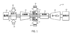
ここで図面を参照すると、図1は、タービンシステム10のブロック図である。図示のタービンシステム10は、燃料噴射器12、燃料供給部14、及び燃焼器16を含む。図示のように、図示のように、燃料供給部14は、天然ガスなどの液体燃料及び/又はガス燃料をガスタービンシステム10に燃料噴射器12を通じて燃焼器16内に送る。燃料噴射器12は、燃料を噴射して圧縮空気と混合させるよう構成される。燃焼器16は、燃料空気混合気を点火して燃焼させ、次いで、高温加圧排出ガスをタービン18に送る。理解されるように、タービン18は、固定ベーン又はブレードを有する1つ又はそれ以上のステータと、ステータに対して回転するブレードを有する1つ又はそれ以上のロータとを含む。排出ガスがタービンロータブレードを通過し、これによりタービンを回転駆動させる。タービンロータとシャフト19との間のカップリングは、シャフト19の回転を引き起こすことになり、該シャフト19はまた、図示のようにガスタービンシステム10全体にわたって複数の構成要素に結合される。最終的に、燃焼プロセスの排気は、排気出口20を介してガスタービンシステム10から出ることができる。
Referring now to the drawings, FIG. 1 is a block diagram of a
圧縮機22は、シャフト19により回転駆動されるロータに堅固に装着されたブレードを含む。空気が回転ブレードを通過すると空気圧が増大し、これにより適正な燃焼のための十分な空気が燃焼器16に提供される。圧縮機22は、吸気口24を介してガスタービンシステム10に空気を吸い込むことができる。更に、シャフト19は負荷26に結合することができ、該負荷は、シャフト19の回転によって動力を供給することができる。理解されるように、負荷26は、発電プラント又は外部の機械的負荷など、ガスタービンシステム10の回転出力の動力を用いることが可能な何らかの好適な装置とすることができる。例えば、負荷26は、発電機、航空機のプロペラ、その他を含むことができる。吸気口24は、低温吸気口などの好適な機構を介してガスタービンシステム10に空気30を引き込む。次いで、空気30は、燃焼器16に圧縮空気32を提供する圧縮機22のブレードを通って流れる。詳細には、燃料噴射器12は、圧縮空気32及び燃料14を燃料空気混合気34として燃焼器16に噴射することができる。或いは、圧縮空気32及び燃料14は、混合及び燃焼のために燃焼器に直接噴射することができる。
The
上記の検討から理解されるように、タービンシステム10は、燃焼プロセスによって生成される高温ガスの経路内の様々な構成要素、すなわち高温ガス経路構成要素を含むことができる。本明細書で使用される場合、高温ガス経路構成要素は、システム10を通過するガスの高温流に少なくとも部分的に曝される、システム10の何れかの構成要素である。例えば、バケット組立体(ブレード又はブレード組立体としても知られる)、ノズル組立体(ベーン又はベーン組立体としても知られる)、シュラウド組立体、移行部品、保持リング、及び圧縮機排出構成要素は、全て高温ガス経路構成要素である。しかしながら、本開示における高温ガス経路構成要素という用語の使用は、上記の実施例に限定されず、高温のガス流に少なくとも部分的に曝される何れかの構成要素とすることができる点は理解されたい。更に、本開示の高温ガス経路構成要素は、ガスタービンシステムの構成要素に限定されず、高温流に曝される可能性がある機械装置の何れかの要素又はその構成要素とすることができる点は理解されたい。
As will be appreciated from the above discussion, the
高温ガス経路構成要素は、高温ガス流に曝されると該高温ガス流によって加熱され、高温ガス経路構成要素が故障するか又は性能が劣化する温度にまで達する場合がある。従って、タービンシステム10が高い温度の高温ガス流で作動して、これによりシステム10の効率及び性能を向上させることができるようにするために、高温ガス経路構成要素の冷却システムを利用することができる。
When exposed to a hot gas stream, the hot gas path component may be heated by the hot gas stream and reach a temperature at which the hot gas path component fails or performance degrades. Accordingly, a cooling system for hot gas path components may be utilized to allow the
一般に、本開示の冷却システムは、タービンシステム10の高温ガス経路構成要素の一部又は全ての表面に形成された、一連の小チャンネル又はマイクロチャンネルを含む。高温ガス経路構成要素はまた、構造コーティング及び/又はトップコーティングのような、1つ又はそれ以上のカバー層を備えることができる。冷却流体は、プレナムからチャンネルに提供することができ、また冷却流体は、チャンネルを通って流れて、構成要素のカバー層すなわちスキンを冷却することができる。このような手法は、本明細書で検討するように、他の手法よりも高い冷却密度(単位表面積又は容積当たりなど)又はより高い冷却効果を提供するようカスタマイズ又は調整することができる。
In general, the cooling system of the present disclosure includes a series of small channels or microchannels formed on some or all surfaces of the hot gas path components of the
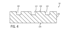
この点を考慮すると、図2は、本発明の手法による高温ガス経路で使用する構成用を形成する方法50を図示している。この実施例では、マイクロチャンネルが形成されることになる部品54を最初に鋳造する(ブロック52)。例えば、中空スパーのような鋳造される部品54は、複雑な内部及び外部チャンネルなしで形成することができる。図3を参照すると、基材層100を有する鋳造部品54の一部が図示されており、ここでは一方の表面102が部品の外部又は外向きの面であり、反対側の表面104が部品54の内部又は内向きの面である。
In view of this, FIG. 2 illustrates a
基材100は通常、基材100の外部表面102内にチャンネル110を形成する前に鋳造される。全目的において引用により全体が本明細書に組み込まれる、同一出願人による米国特許第5,626,462号で検討されるように、基材100は、あらゆる好適な材料から形成することができる。部品54の目的とする用途に応じて、基材は、ニッケル基、コバルト基、及び鉄基超合金を含むことができる。ニッケル基超合金は、γ相及びγ’相の両方を含有するものとすることができ、例えば、このようなニッケル基超合金はγ相及びγ’相の両方を含有し、且つγ’相が容量で超合金の少なくとも40%を占める。このような合金は、高温強度及び高温クリープ抵抗を含む望ましい特性の組み合わせであるので有利であることが知られている。基材の材料はまた、NiAl金属間化合物合金を含むことができ、この合金はまた、航空機で使用されるタービンエンジン用途での使用に有利である高温強度及び高温クリープ抵抗を含む優れた特性の組み合わせを有することが分かっている。ニオブ基合金については、原子パーセントでNb−(27−40)Ti−(4.5−10.5)Al−(4.5−7.9)Cr−(1.5−5.5)Hf−(0−6)Vを備えた合金を含む、Nb/ Ti合金など、優れた酸化抵抗を有する被覆ニオブ基合金を用いることができる。基材材料はまた、ニオブ含有金属間化合物、ニオブ含有炭化物、又はニオブ含有ホウ化物など、少なくとも1つの2次相を含有するニオブ基合金を含むことができる。このような合金は、延性相(すなわち、ニオブ基合金)及び強化相(すなわち、ニオブ含有金属間化合物、ニオブ含有炭化物、又はニオブ含有ホウ化物)を含有する点で、複合材料と類似している。本開示の構成要素基材100は、上述の材料に限定されず、あらゆる高温ガス経路構成要素で使用されるあらゆる材料とすることができる。
The
図2及び4を参照すると、チャンネル10(例えば、マイクロチャンネル)は、部品54の外部表面102内に形成される(ブロック56)。特定の実施形態によれば、チャンネル110は、冷却流体がチャンネル1109を通って流れることができるように設計又は構成される。これにより、冷却流体の流れは、基材10又は基材100の外部表面102上に配置された1つ又はそれ以上の層(以下でより詳細に検討する)から冷却媒体に熱を伝達することなどにより、対流冷却で部品54の隣接領域又は近接領域を冷却することができる。
2 and 4, the channel 10 (eg, microchannel) is formed in the
チャンネル110は、外部表面102内でチャンネル110の所望のサイズ、配置、及び/又は構成を達成するよう、プログラムされ又は自動処理されるプロセス(ロボット制御によるプロセス)の誘導又は制御によって形成又は機械加工することができる。例えば、チャンネル110は、例えば、レーザ機械加工(例えば、レーザ孔加工)、研磨液体ジェット(例えば、研磨マイクロ水ジェット(AμWJ))、電解加工(ECM)、プランジ電解加工(プランジECM)、放電加工(EDM)、回転電極による放電加工(フライスEDM)、又は適正なサイズ及び許容誤差をチャンネルに提供できる他のあらゆるプロセスを使用することにより外部表面102内に形成することができる。
The
特定の実施形態において、チャンネル110は、約0.5mmから約1mmまでなど、約0.2mmから約2mmまでの範囲の深さを有することができる。更に、特定の実施形態において、チャンネル110は、約0.5mmから約1mmまでなど、約0.2mmから約2mmまでの範囲の幅を有することができる。更に、チャンネル110についての幅及び/又は深さは、実質的に一定とすることができ、或いは、チャンネル110にわたって変わる(増大、減少、先細、及びその他など)ことができる。
In certain embodiments, the
例えば、1つの実施において、チャンネル110の幅及び/又は深さは、チャンネル110を通る冷却媒体の流れの方向でチャンネル110の長さに沿って減少することができる。或いは、チャンネル110の幅及び/又は深さは、チャンネル110を通る冷却媒体の流れの方向でチャンネル110の長さに沿って増大することができる。更に、各チャンネル110の幅及び/又は深さは、他のチャンネル110から独立して変わることができ、すなわち、一部のチャンネル110は、冷却媒体の流れの方向で幅及び/又は深さが増大することができ、他のチャンネルは減少することができ、及び/又は増大又は減少の範囲は、チャンネル間で異なることができる。理解されるように、他の実施形態では、チャンネル110の一部又は全ては、幅及び/又は深さが実質的に一定とすることができる。
For example, in one implementation, the width and / or depth of the
加えて、チャンネル110は、例えば、方形、矩形、楕円形、三角形、又はチャンネル110を通る冷却媒体の流れを促進する他の何れかの幾何形状など、あらゆる好適な幾何形状断面を有することができる。種々のチャンネル110は、一定の幾何形状を備えた断面を有することができ、他のチャンネル110は、別の幾何形状を備えた断面を有することができる。加えて、特定の実施形態において、チャンネル110の表面(すなわち、側壁及び/又は床部)は、実質的に平滑な面とすることができるが、他の実施形態では、チャンネル表面の全て又は一部は、突出部、凹部、表面起伏、又はチャンネルの表面が平滑ではないような他の特徴要素を含むことができる。例えば、チャンネル110の表面上に存在できる表面特徴要素は、限定ではないが、フィン型突出部、円筒形突出部、又はタービュレータ、或いはこれらの組み合わせ、並びに他の何れかの好適な幾何形状を含むことができる。存在するあらゆる表面特徴要素の寸法は、それぞれのチャンネル110によって提供される冷却を最適化するよう選択できる点は理解されたい。
In addition, the
更に、チャンネル110は、全体的に直線状のチャンネルとすることができ、或いは、全体的に湾曲又は蛇行したチャンネルとすることができる。例えば、チャンネル110の全て又は一部は、基材100の外部表面102に対して複雑な曲線として、又は3次元構成の一部として設けることができる。実際に、チャンネル110の構成は、部品54に対して、該部品54の特定部分が他よりも高密度の冷却チャンネル110を含むように製造されるよう特異的にすることができる。すなわち、チャンネルの構成は、使用時に部品54の期待される熱プロファイルを考慮して調整することができる。従って、ブレードの先端、プラットフォーム、及び後縁は、一般的にはあまり熱に曝されることのないブレードの他の部分又は他の構成要素よりも高密度の冷却チャンネル110を有して作製することができる。これにより必要とされる場所だけに冷却材を利用することができ、及び/又は他の冷却手法と比べて冷却流を低減可能にすることができる。理解されるように、チャンネル110は、冷却媒体が高温ガス流に対してあらゆる方向でチャンネル110を通って流れるように配向することができる。例えば、冷却媒体は、高温ガス流に対して全体的に上流側、下流側、及び/又は直交方向で、或いは、高温ガス流に対して他の何れかの好適な方向でチャンネル110の一部又は全てを通って流れることができる。
Further, the
一部の実施形態において、チャンネル110の各々は、単一の離散的チャンネルとすることができる。しかしながら、他の実施形態において、チャンネル110の各々又はチャンネル110の何れかの部分は、単一のチャンネル110から分岐して複数チャンネル分岐110を形成することができる。更に、チャンネル110は、一部の実施形態において、高温ガス経路構成要素(すなわち、部品54)の周囲全体に配置することができ、或いは、高温ガス経路構成要素の周囲の一部だけに配置することができる点は理解されたい。しかしながら、チャンネル110の各々は、一般に他の何れかのチャンネル110と交差しないようにすることができる点は更に理解されたい。
In some embodiments, each of the
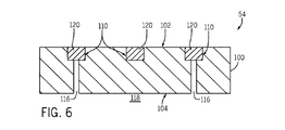
図2及び図5を参照すると、ブロック58において、1つ又はそれ以上の孔116を開け又は穿孔し、チャンネル110の一部又は全てをスパーの内部スペースのような部品により定められる内部領域118に接続することができる。図示するように、孔116は、基材層100を通って全体的に延びることができ、また、チャンネル110を内部スペース118に流体接続し且つチャンネル110の一部又は全てを内部スペース118を介して互いに流体接続することができる。例えば、各チャンネル110は、孔116の少なくとも1つに流体接続することができる。部品54の製造が完了し、チャンネル110が構造コーティング層及び/又は他の層(以下で検討する)により覆われると、孔116は、内部スペース118を介して冷却媒体の流れをチャンネル110に提供可能にすることができる。例えば、構造コーティング層がそれぞれのチャンネル110を覆って所定位置にあると、それぞれの孔116を介した1つ又はそれ以上のチャンネル110への内部スペース118のそれぞれの流体接続によって、少なくとも1つの冷却回路が部品54内に定められ又は部品54の表面上に設けることができる。冷却媒体は、孔116及びチャンネル110内の圧力よりも全体的に高い圧力でこれらの特徴要素により定められる冷却回路を通ることができる。この圧力差により、冷却回路内に含まれる冷却媒体の一部は、孔116内に流入して流れ、孔116からチャンネル110を通過するようになる。冷却媒体は、以下でより詳細に検討するように、ここから1つ又はそれ以上の出口孔(例えば、冷却孔140)を介してチャンネル110から出て、これにより部品54の内部から外部への流れ回路を完成させることができる。
Referring to FIGS. 2 and 5, at
更に、孔116の一部又は全ては、以下で検討するように、それぞれのチャンネル110の上に設けられる構造コーティング130及び/又はトップコーティング134に衝突冷却を提供するよう構成することができる。例えば、孔116は、外部表面102及び/又は構造コーティング130及び/又はトップコーティング134に対して基材100内にほぼ垂直に向けることができる。従って、冷却媒体が孔116を通って流れて、チャンネル110に提供されると、冷却媒体は、孔116から出て構造コーティング130及び/又はトップコーティング134上に衝突し、これによりこれらの層の1つ又は両方を衝突冷却することができる。冷却媒体がチャンネル110を通って流れた後、該冷却媒体は、チャンネル110から直接(部品54の先端又は縁部にてなど)及び/又はチャンネル110を覆うあらゆる層を貫通する排気通路(例えば、冷却孔140)を通って排出することができる。各チャンネル110は、排気通路の1つ又はそれ以上に接続することができる点を理解されたい。更に、排気通路は、チャンネル110に対してあらゆる角度に配向することができる点を理解されたい。
Further, some or all of the
図2から図6を参照すると、各チャンネル110は、1つ又はそれ以上の固体充填材料120を充填することができ(ブロック60)、該充填材料は、後続の段階中に、浸出、溶解、溶融、酸化、エッチング、及びその他などにより化学的に除去することができる。例えば、モリブデン及びタングステン固体充填材料の場合、これらの材料は、700℃を上回って加熱されると昇華する高い蒸気圧の酸化物を有する。特定の実施形態において、充填材料120は、元素又は合金金属材料から形成された固体ワイヤーフィラーである。1つの実施形態において、充填材料は、アニールされた金属ワイヤーなどの変形可能材料であり、チャンネル110内に機械的に圧入されたときに、変形してチャンネル110の形状に共形にされる。本明細書で使用される用語「ワイヤー」は、それぞれのチャンネル110の断面形状に共形になる、又は機械的に変形されて共形になることができる連続した固体材料片を意味する点を理解されたい。従って、本明細書で使用されるワイヤーは、円形の断面を有する必要はないが、代わりに、方形又は矩形断面、或いは、それぞれのチャンネル110内に適合し充填することが可能になる他の何れかの幾何形状断面を有することができる。他の実施形態では、金属又は金属合金材料を粉体として提供してもよく、上述のワイヤーの実施形態と同様に、チャンネル110内に圧入されて該チャンネル110と共形になり、チャンネル110を実質的に充填するようになる。このような1つの実施形態において、金属又は金属合金粉体は、バインダー又はキャリアなしで提供される。1つの実施形態において、金属又は金属合金ワイヤー又は粉体は、チャンネル110内に機械的に圧入され、実質的に又は完全にチャンネル110を充填する。チャンネル110から外に突出する(すなわち、過充填の)固体金属充填材のあらゆる部分は、以下で検討するように、コーティングの施工前に研磨又は機械加工により除去することができ、部品54の露出面及び充填材料120が切れ目のない平滑な面を形成するようになり、その後に層及びコーティングを施工することができる。固体金属充填材を形成するのに用いることができる好適な材料は、限定ではないが、銅、アルミニウム、モリブデン、タングステン、ニッケル、石炭、モネル、ニクロム、及びその他を含むことができる。
Referring to FIGS. 2-6, each
チャンネル110への充填材料120の施工後、基材100の外部表面102は、外部表面102を過ぎて形成又は延びる充填材料120の一部を含む、外部表面102を機械加工、グリットブラスティング、洗浄、及び/又は研磨することになどにより、清浄化されてコーティングの準備を整えることができる。
After application of the
基材100の外部表面102が好適に清浄化され準備されると、図7及び8に示すように、1つ又はそれ以上の表面コーティングを充填材料120上の外部表面102に施工することができる(図2、ブロック64)。コーティング130は、あらゆる好適な材料とすることができ、基材100の外部表面102に接合される。特定の構成において、コーティング130は、工業用構成要素において、0.1から1ミリメートルまでなど、0.1から2.0ミリメートルまでの範囲、或いは、0.1から0.5ミリメートルの範囲の厚みを有する。航空機用構成要素において、この範囲は通常、0.1から0.25ミリメートルである。しかしながら、特定の部品54の要件に応じて、他の厚みを利用することができる。
Once the
コーティング130は、様々な技術を用いて堆積させることができる。特定のプロセスにおいて、コーティング130は、イオンプラズマ堆積法を実施することにより、基材100の外部表面102の少なくとも一部の上に堆積される。例示的なカソードアークイオンプラズマ堆積装置及び方法は、全ての目的において引用により全体が本明細書に組み込まれる、同一出願人の米国特許出願公開第20080138529号、Weaver他、「カソードアークイオンプラズマ堆積の方法及び装置」において提供されている。要約すると、イオンプラズマ堆積は、真空チャンバ内の真空環境にコーティング材料から形成されたカソードを配置する段階と、真空環境内に基材100を提供する段階と、カソードに電流を供給し、カソード表面からコーティング材料の腐食又は蒸発を生じるカソード表面上にカソードアークを形成する段階と、基材表面102上にカソードからのコーティング材料を堆積させる段階と、を含む。
The
非限定的な1つの実施例において、イオンプラズマ堆積プロセスは、プラズマ蒸着プロセスを含む。コーティング130の非限定的な実施例は、米国特許第5,626,462号を参照して以下で詳細に検討するように、金属コーティング、ボンドコート、及び熱障壁コーティングを含む。特定の高温ガス経路構成要素54において、コーティング130は超合金を含む。例えば、基材100がγ相及びγ’相の両方を含有するニッケル基超合金を用いて形成される場合、コーティング130は、米国特許第5,626,462号を参照して以下で詳細に検討するように、これらと同じ材料を含むことができる。
In one non-limiting example, the ion plasma deposition process includes a plasma deposition process. Non-limiting examples of
他のプロセス構成において、コーティング130は、溶射プロセスを実施することにより、基材100の外部表面102の少なくとも一部の上に堆積される。例えば、溶射プロセスは、高速酸素燃料溶射法(high velocity oxygen fuel spraying (HVOF))又は高速空気燃料溶射法(high velocity air fuel spraying(HVAF))を含むことができる。非限定的な1つの実施例において、NiCrAlYコーティングは、HVOF又はHVAFにより堆積される。他の例示的なプロセス構成において、低圧プラズマ溶射(LPPS)プロセスを利用することができる。
In other process configurations, the
より一般的には、米国特許第5,626,462号で検討されるように、コーティング130を形成するのに使用される材料は、あらゆる好適な材料とすることができる。冷却タービン構成要素の場合、コーティング130を形成する材料は、約1150℃の温度に耐え得る必要があるが、熱障壁コーティング(TBC)では約1320℃にまで達する可能性がある。コーティング130は通常、基材100の外部表面102に適合し、これに接合されるよう適応される。この接合は、コーティング130が基材100上に堆積されたときに形成することができる。この接合法は、堆積方法、堆積中の基材100の温度、堆積表面が堆積源に対して偏位しているかどうか、及び他のパラメータを含む、多くのパラメータにより堆積中に影響を受ける可能性がある。接合法はまた、後続の熱処理又は他の処理によって影響される可能性がある。加えて、堆積前の基材100の表面モルホロジー、化学的特性、及び清浄性は、金属結合が生じる程度に影響を及ぼす可能性がある。コーティング130と基材100との間の強い金属結合を形成することに加えて、この結合が、本明細書で説明される相変化及び相互拡散に関して経時的及び高温で安定を維持することが望ましい。適合可能であることによって、ニッケル基合金翼形部支持壁及びニッケル基翼形部外板に対しておよそ1,150℃の高温、或いは、ニオブ基合金のような更に高温の材料が利用される場合のおよそ1300℃の高温に曝されることを考慮しても、接合の強度及び延性が相互拡散又は他のプロセスによって経時的(例えば、最大3年)にあまり劣化しないように、これらの要素間の接合が熱力学的に安定であることが望ましい。
More generally, as discussed in US Pat. No. 5,626,462, the material used to form the
米国特許第5,626,462号で検討されるように、基材100を形成する材料がγ相及びγ’相の両方を含有するニッケル基超合金又はNiAl金属間化合物合金である場合、コーティング130を形成するのに使用される材料は、これらと同じ材料を含むことができる。このようなコーティング130及び基材100の材料の組み合わせは、動作環境の最高温度が既存のエンジンの最高温度(例えば、1650℃未満)と同様である場合のような用途に好適である。基材100を形成するのに使用される材料がニオブ基合金である場合、コーティング130を形成するのに使用される材料はまた、同じニオブ基合金を含む、ニオブ基合金を含むことができる。
As discussed in US Pat. No. 5,626,462, if the material forming the
金属合金コーティング130の使用が望ましくない温度、環境、又は他の制約が課せられる用途など、他の用途に対して米国特許第5,626,462号で検討されるように、コーティング130は、金属間化合物(Is)/金属合金(M)相複合材及び金属間化合物(Is)/金属間化合物(IM)相複合材の一般式の複合材のように、金属合金単独よりも優れた特性を有する材料を用いて形成することができる。金属合金Mは、特定の実施形態において翼形部支持壁に使用されるものと同じ合金とすることができ、或いは、部品54の要件に応じて異なる材料であってもよい。これらの複合材は、比較的延性の相M又はIMと比較的延性の少ない相Isとを組み合わせて両方の材料の利点が得られるコーティング130を生成するようにしている点で、一般的には同様である。更に、良好な複合材を得るため、2つの材料は適合可能である必要がある。複合材に関して本明細書で使用される用語「適合可能」とは、複合材の強度、延性、靱性、及び他の重要な特性を実質的に損なう冶金反応を受けることなく、材料が、所望の初期相分布を形成することができ、1,150℃又はそれ以上の使用温度を上回って上述のような長い時間期間にわたり当該分布を維持できることを意味する。このような適合性はまた、相安定性に関しても表現することができる。すなわち、複合材の分離相は、これらの相が分離し且つ区別して存在し、これらの別個の独自性及び特性を保持しており、相互拡散により単一の相又は複数の異なる相にならないように、長い時間期間にわたるある温度での作動中の安定性を有している。適合性はまた、Is/M又はIs/IM複合材層の間の相間境界界面の形態安定性に関しても表現することができる。このような不安定性は、何れかの層の連続性を崩壊させる畳み込みによって顕在化する場合がある。また、所与のコーティング130内では、複数のIs/M又はIs/IM複合材を使用してもよく、このような複合材は2つの材料又は2つの相の組み合わせに限定されない点に留意されたい。このような組み合わせの使用は、単に例証に過ぎず、実施可能な組み合わせを網羅したものではなく、又はこれに限定されるものではない。従って、M/IM/Is、M/IS1/IS2(ここでIS1及びIS2は異なる材料)及び他の多くの組み合わせが可能である。
As discussed in US Pat. No. 5,626,462 for other applications, such as applications where temperature, environment, or other constraints are imposed where the use of
米国特許第5,626,462号で検討されるように、基材100はγ相及びγ’相両方の混合物を含有するニッケル基超合金を含み、Isは、Ni3[Ti,Ta,Nb,V],NiAl,Cr3Si,[Cr,Mo]XSi,[Ta,Ti,Nb,Hf,Zr,V]C,Cr3C2及びCr7C3金属間化合物及び中間相を含むことができ、Mは、γ相及びγ’相両方の混合物を含有するニッケル基超合金を含むことができる。γ相及びγ’相両方の混合物を含有するニッケル基超合金において、元素Co、Cr、Al、C、及びBは、合金成分としてほぼ常に存在し、Ti、Ta、Nb、V、W、Mo、Re、Hf、及びZrの様々な組み合わせも同様である。従って、ニッケル基超合金で通常見られる1つ又はそれ以上の材料に対応して説明される例示的なIs材料の成分は、基材100を形成するのに用いることができ、従って、本明細書で説明される相及び相互拡散の安定性を達成するよう適応することができる。基材100がNiAl金属間合金を含む場合の追加の実施例として、Isは、Ni3[Ti,Ta,Nb,V],NiAl,Cr3Si,[Cr,Mo]XSi,[Ta,Ti,Nb,Hf,Zr,V]C,Cr3C2及びCr7C3金属間化合物及び中間相を含むことができ、IMは、Ni3Al金属間合金を含むことができる。同様に、NiAl金属間合金において、元素Co、Cr、C、及びBは通常、合金成分として存在し、Ti、Ta、Nb、V、W、Mo、Re、Hf、及びZrの様々な組み合わせも同様である。そのため、NiAl合金で通常見られる1つ又はそれ以上の材料に対応して説明される例示的なIs材料の成分は、基材100を形成するのに用いることができ、従って、本明細書で説明される相及び相互拡散の安定性を達成するよう適応することができる。
As discussed in US Pat. No. 5,626,462,
米国特許第5,626,462号で検討されるように、基材100は、少なくとも1つの2次相を含有するニオブ基合金を含む、ニオブ基合金を含み、Isは、ニオブ含有金属間化合物、ニオブ含有炭化物、又はニオブ含有ホウ化物を含むことができ、Mは、ニオブ基合金を含むことができる。このようなIs/M複合材は、合金のチタンとニオブ(チタン/ニオブ)との原子比が0.2から1の範囲にあり、Is相が、ニオブ基シリサイド、Cr2[Nb,Ti,Hf]、及びニオブ基アルミナイドからなる群を含み、ここでニオブ、とりわけニオブ、チタン、及びハフニウムは、Cr2[Nb,Ti,Hf]の原子単位の主成分であるような、チタン含有ニオブ基合金のM相を含むことができる。これらの化合物は全て、共通する成分としてニオブを有し、従って、米国特許第5,626,462号で記載された相及び相互拡散の安定性を達成するよう適応することができる。
As discussed in US Pat. No. 5,626,462,
図8の図示の実施形態のような、特定の実施形態において、セラミックコーティング又は熱障壁コーティング(TBC)のようなトップコーティング134は、コーティング130の上に施工することができる。例えば、トップコーティング134は、イットリア安定化ジルコニアとすることができ、物理的気相成長プロセス又は溶射プロセスによって構造コーティング130に施工することができる。或いは、トップコーティング134は、IV、V、及びVI族元素から形成された酸化物、又は、ランタン、ニオブ、ガドリウム、イッテルビウム及び同様のものなどのランタニド系列元素により修飾された酸化物のような他の耐火性酸化物によって修飾されたジルコニアの薄層などのセラミックとすることができる。従って、トップコーティング134は、存在する場合に、特定の熱的な利点を部品54に提供することができ、及び/又は特定の仕上げ又は表面起伏上の利点を提供することができる。
In certain embodiments, such as the illustrated embodiment of FIG. 8, a
図2から9を参照すると、何れか及び全ての構造コーティング130及び/又はトップコーティング134が施工されると、1つ又はそれ以上の冷却孔140が、構造コーティング130及び/又はトップコーティング134を通って孔加工(ブロック66)又はパンチ加工され、充填チャンネル110の1つ又はそれ以上に到達する。冷却孔140は、部品54が使用中であるときに排気ポート又は排気孔として機能し、チャンネル110を通って循環する冷却流体がチャンネル110及び部品54から流出し、加熱されたガス中又は部品表面上に分散させてフィルム冷却として使用可能にすることができる。理解されるように、冷却孔140は、あらゆる断面(例えば、円形、方向、矩形、三角形、楕円形、及びその他)又はサイズ、及び冷却流体がチャンネル110から流出するのに好適な向きを有することができる。
2-9, once any and all
図示の実施において、充填材料120は、浸出、溶解、溶融、酸化、エッチング、及びその他などによりチャンネル110から化学的に除去する(図2、ブロック68)ことができる。例えば、1つの実施形態において、充填材料120は、好適な溶液又は化合物を用いてチャンネル110から浸出又は溶解させることができる。充填材料120が固体銅金属ワイヤーのような固体金属充填材である1つの実施形態において、固体金属充填材は、濃硝酸(例えば、67%、50%、40%、及びその他)洗浄液を用いて除去される。他の実施形態では、高濃度苛性ソーダを用いて固体金属充填材を溶解することができる。充填材料の残留物は、冷却孔140及び/又は内部スペース118を介して部品54から出ることができ、その両方は、チャンネル110と流体連通している。充填材料120が除去されると、チャンネル110はクリアにされ、チャンネルの床部及び側壁と、図10に示すように存在する場合には構造コーティング130の内面とによって定められる。
In the illustrated implementation, the
図2を参照すると、図示の実施形態において、チャンネル110の内部表面にコーティングを施工し、チャンネル110を通過する冷却流体の熱及び/又は作用などから、使用中にチャンネル110を保護することができる(ブロック70)。このような1つの実施形態において、耐酸化性コーティングをチャンネル110の内部表面に施工して基材100のチャンネル表面を保護し、及び/又は外部表面102に施工することができる。例えば、1つの実施において、チャンネル110の内部表面をコーティング又は修正し、耐酸化性及び/又は耐高温腐食性を向上させることができる。チャンネル110の内部表面に耐酸化性コーティングを施工する好適な技術は、蒸気相又はスラリークロム化、蒸気相アルミナイジング、パックアルミナイジング、化学気相堆積アルミナイジング、又はスラリーアルミナイジング、或いは、蒸発、スパッタリング、イオンプラズマ堆積、溶射、及び/又はコールドスプレーを介したオーバーレイ堆積を含む。例示的な耐酸化オーバーレイコーティングは、MCrAlYファミリー(M={Ni,Co,Fe})の材料、並びにNiAlXファミリー(X={Cr,Hf,Zr,Y,La,Si,Pt,Pd})から選択された材料を含む。このような1つの実施形態において、耐酸化コーティングはまた、好適な表面の熱障壁ボンドコートとして機能することができる。
Referring to FIG. 2, in the illustrated embodiment, a coating can be applied to the interior surface of the
続いて、部品54を熱処理し(ブロック72)、部品54に施工された種々の層及びコーティングを配置及び/又は仕上げることができる。熱処理後、最終部品は、検討するように、タービンシステム10の組立体において使用される前に、品質管理プロセスの一部として検査することができる。
Subsequently, the
本明細書で説明されるように、高温ガス経路構成要素の表面又はその近傍に位置するチャンネル110及び孔116を利用することにより、本開示の冷却システムは、高い熱伝導率及び比較的均一な温度プロファイルで部品54のような高温ガス経路構成要素の冷却を可能にする。従って、本開示の冷却システムは、高温ガス経路構成要素の寿命を延ばし、該構成要素をより高い温度の高温ガス流と共に利用し、よってタービンシステム10の性能及び効率を高めることができるようにすることができる。更に、本開示の特定の実施形態によれば、タービン10の構成部分のバルク基材100の温度低下をタービン10の作動中に達成することができる。例えば、特定の実施において、基材バルク温度は、約1300°Fから約1800°Fの間とすることができる。
As described herein, by utilizing
本明細書は、最良の形態を含む実施例を用いて本発明を開示し、更に、あらゆる当業者があらゆるデバイス又はシステムを実施及び利用すること並びにあらゆる包含の方法を実施することを含む本発明を実施することを可能にする。本明細書で提供される代表的な実施例及び実施形態は、互いに組み合わせることができる特徴要素、並びに本発明の範囲内に依然として含まれる追加の実施形態を形成するための他の開示された実施形態又は実施例の特徴要素と組み合わせることができる特徴要素を含む。本発明の特許保護される範囲は、請求項によって定義され、当業者であれば想起される他の実施例を含むことができる。このような他の実施例は、請求項の文言と差違のない構造要素を有する場合、或いは、請求項の文言と僅かな差違を有する均等な構造要素を含む場合には、本発明の範囲内にあるものとする。 This written description discloses the invention using examples, including the best mode, and further includes any person skilled in the art to make and use any device or system and any method of inclusion. It is possible to carry out. The representative examples and embodiments provided herein are features that can be combined with each other, as well as other disclosed implementations to form additional embodiments that still fall within the scope of the invention. Includes features that can be combined with features of the form or example. The patentable scope of the invention is defined by the claims, and may include other examples that occur to those skilled in the art. Such other embodiments are within the scope of the invention if they have structural elements that do not differ from the words of the claims, or if they contain equivalent structural elements that have slight differences from the words of the claims. It shall be in
10 タービンシステム
12 燃料噴射器
14 燃料
16 燃焼器
18 タービン
19 シャフト
20 排出出口
22 圧縮機
24 吸気口
26 負荷
30 空気
32 圧縮空気
34 燃料−空気混合気
50 方法
52 鋳造部品
54 部品
56 チャンネルを形成
58 チャンネルと内部領域とを接続する孔を形成
60 充填材料でチャンネルを充填する
64 表面コーティングを施工する
66 冷却孔を穿孔する
68 充填材料を除去する
70 コーティングを施工
72 熱処理部品
100 基材
102 外部表面
104 内部表面
110 チャンネル
116 孔
118 内部スペース
120 充填材料
130 構造層/コーティング
134 トップコーティング
140 冷却孔
10
Claims (10)
前記タービン構成要素(54)の外部表面(102)内に1つ又はそれ以上のチャンネル(110)を形成する段階(56)と、
前記1つ又はそれ以上のチャンネル(110)と前記タービン構成要素(54)の内部領域(118)との間に1つ又はそれ以上の第1の孔(116)を形成する段階(58)と、
1つのフィラー材料を前記1つ又はそれ以上のチャンネル(110)内に機械的に圧入し、前記1つ又はそれ以上のチャンネル(110)に形状を一致させ実質的に充填するようにする段階(60)と、
を含み、
前記1つのフィラー材料は、前記チャンネル(110)の各々の断面に形状が一致する金属又は金属合金ワイヤーを含み、
前記方法は、さらに、
前記金属又は金属合金ワイヤーで充填された前記1つ又はそれ以上のチャンネル(110)上で前記タービン構成要素(54)の外部表面(102)に1つ又はそれ以上のコーティング(130)を施工する段階(64)と、
前記第1の孔(116)が形成されていない前記チャンネル(110)に対して、前記コーティング(130)を通して1つ又はそれ以上の第2の孔(140)を形成する段階(66)と、
前記チャンネル(110)から前記金属又は金属合金ワイヤーを除去する段階(68)と、
を含む、方法。 A method of manufacturing a turbine component (54), comprising:
Forming one or more channels (110) in the outer surface (102) of the turbine component (54);
Forming one or more first holes (116) between the one or more channels (110) and an interior region (118) of the turbine component (54); ,
Mechanically injecting one filler material into the one or more channels (110) to conform and substantially fill the one or more channels (110) ( 60)
Including
The one filler material includes a metal or metal alloy wire whose shape matches the cross section of each of the channels (110),
The method further comprises:
One or more coatings (130) are applied to the outer surface (102) of the turbine component (54) on the one or more channels (110) filled with the metal or metal alloy wire. Stage (64);
Forming (66) one or more second holes (140) through the coating (130) for the channel (110) in which the first holes (116) are not formed;
Removing the metal or metal alloy wire from the channel (110) (68);
Including a method.
After removing (68) the metal or metal alloy wire from the channel (110), applying an oxidation resistant coating to one or both of the surface of the channel or the external surface of the turbine component (54). 10. The method according to any one of claims 1 to 9, comprising (70).
Applications Claiming Priority (2)
| Application Number | Priority Date | Filing Date | Title |
|---|---|---|---|
| US12/953,177 | 2010-11-23 | ||
| US12/953,177 US8739404B2 (en) | 2010-11-23 | 2010-11-23 | Turbine components with cooling features and methods of manufacturing the same |
Publications (3)
| Publication Number | Publication Date |
|---|---|
| JP2012112381A JP2012112381A (en) | 2012-06-14 |
| JP2012112381A5 JP2012112381A5 (en) | 2014-12-25 |
| JP5965132B2 true JP5965132B2 (en) | 2016-08-03 |
Family
ID=46026210
Family Applications (1)
| Application Number | Title | Priority Date | Filing Date |
|---|---|---|---|
| JP2011251175A Active JP5965132B2 (en) | 2010-11-23 | 2011-11-17 | Turbine component with cooling features and method of manufacturing the same |
Country Status (5)
| Country | Link |
|---|---|
| US (1) | US8739404B2 (en) |
| JP (1) | JP5965132B2 (en) |
| CN (1) | CN102554564B (en) |
| DE (1) | DE102011055612B4 (en) |
| FR (1) | FR2967715B1 (en) |
Families Citing this family (48)
| Publication number | Priority date | Publication date | Assignee | Title |
|---|---|---|---|---|
| US8673397B2 (en) | 2010-11-10 | 2014-03-18 | General Electric Company | Methods of fabricating and coating a component |
| US8601691B2 (en) | 2011-04-27 | 2013-12-10 | General Electric Company | Component and methods of fabricating a coated component using multiple types of fillers |
| US20120295061A1 (en) * | 2011-05-18 | 2012-11-22 | General Electric Company | Components with precision surface channels and hybrid machining method |
| US9206696B2 (en) | 2011-08-16 | 2015-12-08 | General Electric Company | Components with cooling channels and methods of manufacture |
| US9260191B2 (en) * | 2011-08-26 | 2016-02-16 | Hs Marston Aerospace Ltd. | Heat exhanger apparatus including heat transfer surfaces |
| US20130086784A1 (en) | 2011-10-06 | 2013-04-11 | General Electric Company | Repair methods for cooled components |
| US9435208B2 (en) | 2012-04-17 | 2016-09-06 | General Electric Company | Components with microchannel cooling |
| US9243503B2 (en) * | 2012-05-23 | 2016-01-26 | General Electric Company | Components with microchannel cooled platforms and fillets and methods of manufacture |
| CN102773667A (en) * | 2012-07-17 | 2012-11-14 | 樊荣 | Machining technology of ship bent rudder stock |
| DE102013109116A1 (en) * | 2012-08-27 | 2014-03-27 | General Electric Company (N.D.Ges.D. Staates New York) | Component with cooling channels and method of manufacture |
| US9238265B2 (en) | 2012-09-27 | 2016-01-19 | General Electric Company | Backstrike protection during machining of cooling features |
| US9527262B2 (en) * | 2012-09-28 | 2016-12-27 | General Electric Company | Layered arrangement, hot-gas path component, and process of producing a layered arrangement |
| US9335296B2 (en) | 2012-10-10 | 2016-05-10 | Westinghouse Electric Company Llc | Systems and methods for steam generator tube analysis for detection of tube degradation |
| US9297267B2 (en) | 2012-12-10 | 2016-03-29 | General Electric Company | System and method for removing heat from a turbine |
| US9664111B2 (en) | 2012-12-19 | 2017-05-30 | United Technologies Corporation | Closure of cooling holes with a filing agent |
| US9884343B2 (en) | 2012-12-20 | 2018-02-06 | United Technologies Corporation | Closure of cooling holes with a filling agent |
| US9273559B2 (en) * | 2013-03-08 | 2016-03-01 | General Electric Company | Turbine blade cooling channel formation |
| US9803939B2 (en) * | 2013-11-22 | 2017-10-31 | General Electric Company | Methods for the formation and shaping of cooling channels, and related articles of manufacture |
| US9476306B2 (en) | 2013-11-26 | 2016-10-25 | General Electric Company | Components with multi-layered cooling features and methods of manufacture |
| CN103707016B (en) * | 2013-12-10 | 2016-09-21 | 中国南方航空工业(集团)有限公司 | The wire pulling method method of powder metallurgy superalloy turbine disc tongue-and-groove |
| CN103949864B (en) * | 2014-04-04 | 2016-03-30 | 上海第一水泵厂有限公司 | A kind of processing method of blade of interrupted cut |
| CN109907828B (en) * | 2014-04-22 | 2022-04-08 | 香港生物医学工程有限公司 | Surgical device |
| US10731857B2 (en) * | 2014-09-09 | 2020-08-04 | Raytheon Technologies Corporation | Film cooling circuit for a combustor liner |
| EP3018415B1 (en) * | 2014-11-07 | 2020-01-01 | United Technologies Corporation | Combustor dilution hole cooling |
| US10450871B2 (en) | 2015-02-26 | 2019-10-22 | Rolls-Royce Corporation | Repair of dual walled metallic components using directed energy deposition material addition |
| US10766105B2 (en) | 2015-02-26 | 2020-09-08 | Rolls-Royce Corporation | Repair of dual walled metallic components using braze material |
| US9970302B2 (en) | 2015-06-15 | 2018-05-15 | General Electric Company | Hot gas path component trailing edge having near wall cooling features |
| US9897006B2 (en) | 2015-06-15 | 2018-02-20 | General Electric Company | Hot gas path component cooling system having a particle collection chamber |
| US9938899B2 (en) | 2015-06-15 | 2018-04-10 | General Electric Company | Hot gas path component having cast-in features for near wall cooling |
| US9828915B2 (en) * | 2015-06-15 | 2017-11-28 | General Electric Company | Hot gas path component having near wall cooling features |
| CA2935398A1 (en) | 2015-07-31 | 2017-01-31 | Rolls-Royce Corporation | Turbine airfoils with micro cooling features |
| US10378380B2 (en) * | 2015-12-16 | 2019-08-13 | General Electric Company | Segmented micro-channel for improved flow |
| US10221719B2 (en) | 2015-12-16 | 2019-03-05 | General Electric Company | System and method for cooling turbine shroud |
| US20170175574A1 (en) * | 2015-12-16 | 2017-06-22 | General Electric Company | Method for metering micro-channel circuit |
| US10309252B2 (en) | 2015-12-16 | 2019-06-04 | General Electric Company | System and method for cooling turbine shroud trailing edge |
| US10017844B2 (en) | 2015-12-18 | 2018-07-10 | General Electric Company | Coated articles and method for making |
| US10704395B2 (en) * | 2016-05-10 | 2020-07-07 | General Electric Company | Airfoil with cooling circuit |
| US10689984B2 (en) | 2016-09-13 | 2020-06-23 | Rolls-Royce Corporation | Cast gas turbine engine cooling components |
| US10465607B2 (en) * | 2017-04-05 | 2019-11-05 | United Technologies Corporation | Method of manufacturing conductive film holes |
| DE102017209229B4 (en) | 2017-05-31 | 2020-07-16 | Hermle Maschinenbau Gmbh | Process for producing a component and intermediate product in the production of a component |
| US10487672B2 (en) | 2017-11-20 | 2019-11-26 | Rolls-Royce Corporation | Airfoil for a gas turbine engine having insulating materials |
| US11338396B2 (en) | 2018-03-08 | 2022-05-24 | Rolls-Royce Corporation | Techniques and assemblies for joining components |
| US11090771B2 (en) | 2018-11-05 | 2021-08-17 | Rolls-Royce Corporation | Dual-walled components for a gas turbine engine |
| US11305363B2 (en) | 2019-02-11 | 2022-04-19 | Rolls-Royce Corporation | Repair of through-hole damage using braze sintered preform |
| US11935662B2 (en) | 2019-07-02 | 2024-03-19 | Westinghouse Electric Company Llc | Elongate SiC fuel elements |
| ES2955292T3 (en) | 2019-09-19 | 2023-11-29 | Westinghouse Electric Co Llc | Apparatus for performing in-situ adhesion testing of cold spray tanks and procedure for use |
| US11548102B2 (en) | 2020-07-31 | 2023-01-10 | General Electric Company | Method for repairing composite components using a plug |
| US11692446B2 (en) | 2021-09-23 | 2023-07-04 | Rolls-Royce North American Technologies, Inc. | Airfoil with sintered powder components |
Family Cites Families (85)
| Publication number | Priority date | Publication date | Assignee | Title |
|---|---|---|---|---|
| US2641439A (en) * | 1947-10-01 | 1953-06-09 | Chrysler Corp | Cooled turbine or compressor blade |
| US3963368A (en) | 1967-12-19 | 1976-06-15 | General Motors Corporation | Turbine cooling |
| US3698834A (en) | 1969-11-24 | 1972-10-17 | Gen Motors Corp | Transpiration cooling |
| US3656863A (en) | 1970-07-27 | 1972-04-18 | Curtiss Wright Corp | Transpiration cooled turbine rotor blade |
| US4040159A (en) * | 1975-10-29 | 1977-08-09 | General Electric Company | Method of manufacture of cooled airfoil-shaped bucket |
| US4118146A (en) | 1976-08-11 | 1978-10-03 | United Technologies Corporation | Coolable wall |
| US4311433A (en) | 1979-01-16 | 1982-01-19 | Westinghouse Electric Corp. | Transpiration cooled ceramic blade for a gas turbine |
| US4314794A (en) | 1979-10-25 | 1982-02-09 | Westinghouse Electric Corp. | Transpiration cooled blade for a gas turbine engine |
| WO1992019851A2 (en) | 1991-05-07 | 1992-11-12 | Stephen Molivadas | Airtight two-phase heat-transfer systems |
| US4583914A (en) | 1982-06-14 | 1986-04-22 | United Technologies Corp. | Rotor blade for a rotary machine |
| US4527386A (en) | 1983-02-28 | 1985-07-09 | United Technologies Corporation | Diffuser for gas turbine engine |
| DE3327218A1 (en) | 1983-07-28 | 1985-02-07 | MTU Motoren- und Turbinen-Union München GmbH, 8000 München | THERMALLY HIGH-QUALITY, COOLED COMPONENT, IN PARTICULAR TURBINE BLADE |
| US4672727A (en) * | 1985-12-23 | 1987-06-16 | United Technologies Corporation | Method of fabricating film cooling slot in a hollow airfoil |
| US4896510A (en) | 1987-02-06 | 1990-01-30 | General Electric Company | Combustor liner cooling arrangement |
| US4768700A (en) * | 1987-08-17 | 1988-09-06 | General Motors Corporation | Diffusion bonding method |
| JP2716480B2 (en) | 1988-10-18 | 1998-02-18 | 西脇 邦彦 | Gas turbine blade cooling method |
| JPH03210029A (en) | 1990-01-10 | 1991-09-13 | Nissan Motor Co Ltd | Enclosure device for gas turbine engine |
| US5383766A (en) | 1990-07-09 | 1995-01-24 | United Technologies Corporation | Cooled vane |
| US5075966A (en) * | 1990-09-04 | 1991-12-31 | General Electric Company | Method for fabricating a hollow component for a rocket engine |
| US5352272A (en) | 1991-01-30 | 1994-10-04 | The Dow Chemical Company | Gas separations utilizing glassy polymer membranes at sub-ambient temperatures |
| JP3210029B2 (en) | 1991-06-11 | 2001-09-17 | キヤノン株式会社 | Image processing apparatus and method |
| IT1255613B (en) | 1992-09-24 | 1995-11-09 | Eniricerche Spa | LOW EMISSION COMBUSTION SYSTEM FOR GAS TURBINES |
| US5249357A (en) * | 1993-01-27 | 1993-10-05 | The United States Of America As Represented By The Administrator Of The National Aeronautics And Space Administration | Method of fabricating a rocket engine combustion chamber |
| IT1273369B (en) | 1994-03-04 | 1997-07-08 | Nuovo Pignone Spa | IMPROVED LOW EMISSION COMBUSTION SYSTEM FOR GAS TURBINES |
| US5626462A (en) | 1995-01-03 | 1997-05-06 | General Electric Company | Double-wall airfoil |
| US5640767A (en) | 1995-01-03 | 1997-06-24 | Gen Electric | Method for making a double-wall airfoil |
| UA23886C2 (en) * | 1996-03-12 | 2002-04-15 | Юнайтед Технолоджіз Корп. Пратт Енд Уітні | METHOD OF MANUFACTURE OF HOLLOW PRODUCTS OF COMPLEX FORM |
| US6035644A (en) | 1997-02-19 | 2000-03-14 | Hps Merrimac | Turbine control valve |
| JP3411775B2 (en) | 1997-03-10 | 2003-06-03 | 三菱重工業株式会社 | Gas turbine blade |
| US5875549A (en) * | 1997-03-17 | 1999-03-02 | Siemens Westinghouse Power Corporation | Method of forming internal passages within articles and articles formed by same |
| WO1998049496A1 (en) | 1997-04-30 | 1998-11-05 | Siemens Westinghouse Power Corporation | An apparatus for cooling a combuster, and a method of same |
| WO1999006771A1 (en) | 1997-07-31 | 1999-02-11 | Alliedsignal Inc. | Rib turbulators for combustor external cooling |
| DE19737845C2 (en) * | 1997-08-29 | 1999-12-02 | Siemens Ag | Method for producing a gas turbine blade, and gas turbine blade produced using the method |
| JP4976614B2 (en) | 1997-10-27 | 2012-07-18 | シーメンス エナジー インコーポレイテッド | Superalloy casting method |
| FR2781707B1 (en) * | 1998-07-30 | 2000-09-08 | Snecma | METHOD FOR MACHINING BY EXCIMER LASER OF HOLES OR SHAPES WITH VARIABLE PROFILE |
| US6321449B2 (en) * | 1998-11-12 | 2001-11-27 | General Electric Company | Method of forming hollow channels within a component |
| US6214248B1 (en) * | 1998-11-12 | 2001-04-10 | General Electric Company | Method of forming hollow channels within a component |
| US6247896B1 (en) | 1999-06-23 | 2001-06-19 | United Technologies Corporation | Method and apparatus for cooling an airfoil |
| US6213714B1 (en) | 1999-06-29 | 2001-04-10 | Allison Advanced Development Company | Cooled airfoil |
| GB2355017B (en) | 1999-09-23 | 2001-09-12 | Lorenzo Battisti | Porous element |
| US6280140B1 (en) | 1999-11-18 | 2001-08-28 | United Technologies Corporation | Method and apparatus for cooling an airfoil |
| GB2356684A (en) | 1999-11-24 | 2001-05-30 | Lorenzo Battisti | Boundary layer control using electroformed microporous material |
| WO2001040713A1 (en) | 1999-12-03 | 2001-06-07 | Mowill Rolf Jan | Cooled premixer exit nozzle for gas turbine combustor and method of operation therefor |
| US6374158B1 (en) * | 2000-02-15 | 2002-04-16 | General Electric Company | Robotic laser pointer |
| US6339879B1 (en) * | 2000-08-29 | 2002-01-22 | General Electric Company | Method of sizing and forming a cooling hole in a gas turbine engine component |
| US6427446B1 (en) | 2000-09-19 | 2002-08-06 | Power Systems Mfg., Llc | Low NOx emission combustion liner with circumferentially angled film cooling holes |
| US6617003B1 (en) | 2000-11-06 | 2003-09-09 | General Electric Company | Directly cooled thermal barrier coating system |
| US6443700B1 (en) | 2000-11-08 | 2002-09-03 | General Electric Co. | Transpiration-cooled structure and method for its preparation |
| US6427327B1 (en) * | 2000-11-29 | 2002-08-06 | General Electric Company | Method of modifying cooled turbine components |
| US6528118B2 (en) | 2001-02-06 | 2003-03-04 | General Electric Company | Process for creating structured porosity in thermal barrier coating |
| US6499949B2 (en) | 2001-03-27 | 2002-12-31 | Robert Edward Schafrik | Turbine airfoil trailing edge with micro cooling channels |
| US6461108B1 (en) | 2001-03-27 | 2002-10-08 | General Electric Company | Cooled thermal barrier coating on a turbine blade tip |
| US6461107B1 (en) * | 2001-03-27 | 2002-10-08 | General Electric Company | Turbine blade tip having thermal barrier coating-formed micro cooling channels |
| US6551061B2 (en) | 2001-03-27 | 2003-04-22 | General Electric Company | Process for forming micro cooling channels inside a thermal barrier coating system without masking material |
| JP2002317641A (en) * | 2001-04-24 | 2002-10-31 | Ishikawajima Harima Heavy Ind Co Ltd | Turbine housing inner wall spray method |
| US7204019B2 (en) * | 2001-08-23 | 2007-04-17 | United Technologies Corporation | Method for repairing an apertured gas turbine component |
| US6380512B1 (en) * | 2001-10-09 | 2002-04-30 | Chromalloy Gas Turbine Corporation | Method for removing coating material from a cooling hole of a gas turbine engine component |
| US6568187B1 (en) | 2001-12-10 | 2003-05-27 | Power Systems Mfg, Llc | Effusion cooled transition duct |
| GB2384046B (en) | 2002-01-15 | 2005-07-06 | Rolls Royce Plc | A double wall combuster tile arrangement |
| DE50214427D1 (en) | 2002-01-17 | 2010-06-24 | Siemens Ag | Cast turbine vane with hook base |
| WO2004013368A1 (en) * | 2002-08-02 | 2004-02-12 | Mitsubishi Heavy Industries, Ltd. | Method for forming heat shielding film, masking pin and tail pipe of combustor |
| JP2004115846A (en) * | 2002-09-25 | 2004-04-15 | Mitsubishi Heavy Ind Ltd | Automatic thermal spraying system, and automatic thermal spraying method |
| EP1496140A1 (en) | 2003-07-09 | 2005-01-12 | Siemens Aktiengesellschaft | Layered structure and process for producing a layered structure |
| EP1510283B1 (en) * | 2003-08-27 | 2007-10-17 | ALSTOM Technology Ltd | Automated adaptive machining of obstructed passages |
| US6905302B2 (en) * | 2003-09-17 | 2005-06-14 | General Electric Company | Network cooled coated wall |
| JP4191578B2 (en) | 2003-11-21 | 2008-12-03 | 三菱重工業株式会社 | Turbine cooling blade of gas turbine engine |
| US7004720B2 (en) | 2003-12-17 | 2006-02-28 | Pratt & Whitney Canada Corp. | Cooled turbine vane platform |
| US7146816B2 (en) | 2004-08-16 | 2006-12-12 | Honeywell International, Inc. | Effusion momentum control |
| US7308794B2 (en) | 2004-08-27 | 2007-12-18 | Pratt & Whitney Canada Corp. | Combustor and method of improving manufacturing accuracy thereof |
| US7252480B2 (en) * | 2004-12-17 | 2007-08-07 | General Electric Company | Methods for generation of dual thickness internal pack coatings and objects produced thereby |
| ATE513980T1 (en) * | 2004-12-24 | 2011-07-15 | Alstom Technology Ltd | METHOD FOR PRODUCING A COMPONENT WITH AN EMBEDDED CHANNEL AND COMPONENT |
| US7546737B2 (en) | 2006-01-24 | 2009-06-16 | Honeywell International Inc. | Segmented effusion cooled gas turbine engine combustor |
| US7950233B2 (en) | 2006-03-31 | 2011-05-31 | Pratt & Whitney Canada Corp. | Combustor |
| US7611324B2 (en) | 2006-11-30 | 2009-11-03 | General Electric Company | Method and system to facilitate enhanced local cooling of turbine engines |
| US7879203B2 (en) | 2006-12-11 | 2011-02-01 | General Electric Company | Method and apparatus for cathodic arc ion plasma deposition |
| US8769963B2 (en) | 2007-01-30 | 2014-07-08 | Siemens Energy, Inc. | Low leakage spring clip/ring combinations for gas turbine engine |
| JP5173211B2 (en) * | 2007-02-22 | 2013-04-03 | 三菱重工業株式会社 | Metal member having hollow hole and processing method thereof |
| US7836703B2 (en) * | 2007-06-20 | 2010-11-23 | General Electric Company | Reciprocal cooled turbine nozzle |
| US8127552B2 (en) | 2008-01-18 | 2012-03-06 | Honeywell International, Inc. | Transition scrolls for use in turbine engine assemblies |
| GB2457073B (en) | 2008-02-04 | 2010-05-05 | Rolls-Royce Plc | Gas Turbine Component Film Cooling Airflow Modulation |
| US8001793B2 (en) | 2008-08-29 | 2011-08-23 | Pratt & Whitney Canada Corp. | Gas turbine engine reverse-flow combustor |
| US20120114868A1 (en) | 2010-11-10 | 2012-05-10 | General Electric Company | Method of fabricating a component using a fugitive coating |
| US8673397B2 (en) | 2010-11-10 | 2014-03-18 | General Electric Company | Methods of fabricating and coating a component |
| EP3018415B1 (en) | 2014-11-07 | 2020-01-01 | United Technologies Corporation | Combustor dilution hole cooling |
| US10689984B2 (en) | 2016-09-13 | 2020-06-23 | Rolls-Royce Corporation | Cast gas turbine engine cooling components |
-
2010
- 2010-11-23 US US12/953,177 patent/US8739404B2/en active Active
-
2011
- 2011-11-17 JP JP2011251175A patent/JP5965132B2/en active Active
- 2011-11-22 DE DE102011055612.5A patent/DE102011055612B4/en active Active
- 2011-11-23 CN CN201110393257.4A patent/CN102554564B/en active Active
- 2011-11-23 FR FR1160706A patent/FR2967715B1/en not_active Expired - Fee Related
Also Published As
| Publication number | Publication date |
|---|---|
| DE102011055612A1 (en) | 2012-06-28 |
| US8739404B2 (en) | 2014-06-03 |
| CN102554564B (en) | 2017-03-01 |
| US20120124832A1 (en) | 2012-05-24 |
| DE102011055612B4 (en) | 2022-10-13 |
| JP2012112381A (en) | 2012-06-14 |
| FR2967715B1 (en) | 2018-04-27 |
| FR2967715A1 (en) | 2012-05-25 |
| CN102554564A (en) | 2012-07-11 |
Similar Documents
| Publication | Publication Date | Title |
|---|---|---|
| JP5965132B2 (en) | Turbine component with cooling features and method of manufacturing the same | |
| JP5941266B2 (en) | COMPONENT COMPRISING DUCTION-shaped COOLING CHANNEL AND METHOD | |
| JP5997438B2 (en) | Component with cooling channel and manufacturing method | |
| EP3112594B1 (en) | Hot gas path component trailing edge having near wall cooling features | |
| JP6537162B2 (en) | Part with multi-layer cooling features and method of manufacture | |
| EP3106619B1 (en) | Hot gas path component having nea r wall cooling features | |
| RU2616335C2 (en) | Turbine element of gas turbine engine with microchannel cooling (versions) | |
| JP6192982B2 (en) | MICROCHANNEL COOLING PLATFORM, PARTS HAVING FILLET AND MANUFACTURING METHOD | |
| JP6145295B2 (en) | Components with microchannel cooling | |
| JP6348270B2 (en) | Component with microcooled coating layer and manufacturing method | |
| US9248530B1 (en) | Backstrike protection during machining of cooling features | |
| JP2012102731A (en) | Method of fabricating component using fugitive coating | |
| JP2014224526A (en) | Components with double sided cooling features and methods of manufacturing the same | |
| US9297267B2 (en) | System and method for removing heat from a turbine | |
| JP6254820B2 (en) | Component with microcooled patterning coating layer and method of manufacturing | |
| US9242294B2 (en) | Methods of forming cooling channels using backstrike protection |
Legal Events
| Date | Code | Title | Description |
|---|---|---|---|
| A521 | Request for written amendment filed |
Free format text: JAPANESE INTERMEDIATE CODE: A523 Effective date: 20141112 |
|
| A621 | Written request for application examination |
Free format text: JAPANESE INTERMEDIATE CODE: A621 Effective date: 20141112 |
|
| A977 | Report on retrieval |
Free format text: JAPANESE INTERMEDIATE CODE: A971007 Effective date: 20151106 |
|
| A131 | Notification of reasons for refusal |
Free format text: JAPANESE INTERMEDIATE CODE: A131 Effective date: 20151208 |
|
| A521 | Request for written amendment filed |
Free format text: JAPANESE INTERMEDIATE CODE: A523 Effective date: 20160302 |
|
| TRDD | Decision of grant or rejection written | ||
| A01 | Written decision to grant a patent or to grant a registration (utility model) |
Free format text: JAPANESE INTERMEDIATE CODE: A01 Effective date: 20160607 |
|
| A61 | First payment of annual fees (during grant procedure) |
Free format text: JAPANESE INTERMEDIATE CODE: A61 Effective date: 20160701 |
|
| R150 | Certificate of patent or registration of utility model |
Ref document number: 5965132 Country of ref document: JP Free format text: JAPANESE INTERMEDIATE CODE: R150 |
|
| R250 | Receipt of annual fees |
Free format text: JAPANESE INTERMEDIATE CODE: R250 |
|
| R250 | Receipt of annual fees |
Free format text: JAPANESE INTERMEDIATE CODE: R250 |
|
| R250 | Receipt of annual fees |
Free format text: JAPANESE INTERMEDIATE CODE: R250 |
|
| R250 | Receipt of annual fees |
Free format text: JAPANESE INTERMEDIATE CODE: R250 |
|
| R250 | Receipt of annual fees |
Free format text: JAPANESE INTERMEDIATE CODE: R250 |
|
| S111 | Request for change of ownership or part of ownership |
Free format text: JAPANESE INTERMEDIATE CODE: R313113 |
|
| R350 | Written notification of registration of transfer |
Free format text: JAPANESE INTERMEDIATE CODE: R350 |