JP5963783B2 - Microcontroller with CAN bus module and automatic speed detection - Google Patents
Microcontroller with CAN bus module and automatic speed detection Download PDFInfo
- Publication number
- JP5963783B2 JP5963783B2 JP2013557739A JP2013557739A JP5963783B2 JP 5963783 B2 JP5963783 B2 JP 5963783B2 JP 2013557739 A JP2013557739 A JP 2013557739A JP 2013557739 A JP2013557739 A JP 2013557739A JP 5963783 B2 JP5963783 B2 JP 5963783B2
- Authority
- JP
- Japan
- Prior art keywords
- microcontroller
- frequency
- area network
- module
- controller area
- Prior art date
- Legal status (The legal status is an assumption and is not a legal conclusion. Google has not performed a legal analysis and makes no representation as to the accuracy of the status listed.)
- Active
Links
Images


Classifications
-
- H—ELECTRICITY
- H04—ELECTRIC COMMUNICATION TECHNIQUE
- H04L—TRANSMISSION OF DIGITAL INFORMATION, e.g. TELEGRAPHIC COMMUNICATION
- H04L25/00—Baseband systems
- H04L25/02—Details ; arrangements for supplying electrical power along data transmission lines
-
- H—ELECTRICITY
- H04—ELECTRIC COMMUNICATION TECHNIQUE
- H04L—TRANSMISSION OF DIGITAL INFORMATION, e.g. TELEGRAPHIC COMMUNICATION
- H04L25/00—Baseband systems
- H04L25/02—Details ; arrangements for supplying electrical power along data transmission lines
- H04L25/0262—Arrangements for detecting the data rate of an incoming signal
-
- H—ELECTRICITY
- H04—ELECTRIC COMMUNICATION TECHNIQUE
- H04L—TRANSMISSION OF DIGITAL INFORMATION, e.g. TELEGRAPHIC COMMUNICATION
- H04L9/00—Cryptographic mechanisms or cryptographic arrangements for secret or secure communications; Network security protocols
- H04L9/40—Network security protocols
Description
(技術分野)
本発明は、コントローラエリアネットワーク(CAN)モジュールを有するマイクロコントローラに関する。
(Technical field)
The present invention relates to a microcontroller having a controller area network (CAN) module.
(背景)
コントローラエリアネットワーク(CAN)は、高レベルのセキュリティによって、分散型リアルタイム制御を効率的にサポートするシリアル通信プロトコルである。CANの用途は、高速デジタル通信ネットワークから低コスト多重配線まで及ぶ。CANは、リアルタイム用途のための高信頼性シリアルデータ通信バスである。CANは、1秒あたり最大1メガビットのデータレートで動作し、優れたエラー検出および閉じ込め性能を有し、元来は、自動車内において使用するために開発された。CANの背後にある動機は、自動車用電子機器、エンジン制御ユニット、センサ、横滑り防止システム等の相互運用性を改善する一方、配線用ハーネス重量および複雑性を低減させることによって、自動車をより信頼性があり、安全、かつ燃料効率的にするというものであった。CANの出現以来、産業オートメーションおよび自動車/トラック用途において、CANプロトコルが、広く普及している。騒音環境におけるCANバスのロバスト性ならびに故障状態の検出およびそこからの回復能力は、CANを産業制御機器、医療機器、試験機器、モバイルおよびポータブル機械、器具等と併用するために好適なものにしている。
(background)
The Controller Area Network (CAN) is a serial communication protocol that efficiently supports distributed real-time control with a high level of security. CAN applications range from high-speed digital communication networks to low-cost multiplex wiring. CAN is a reliable serial data communication bus for real-time applications. CAN operates at data rates up to 1 megabit per second, has excellent error detection and containment performance, and was originally developed for use in automobiles. The motivation behind CAN improves the interoperability of automotive electronics, engine control units, sensors, skid prevention systems, etc., while reducing the wiring harness weight and complexity, making the vehicle more reliable It was to be safe and fuel efficient. Since the advent of CAN, the CAN protocol has become widespread in industrial automation and automotive / truck applications. The robustness of CAN buses in noisy environments and the ability to detect and recover from fault conditions makes CAN suitable for use with industrial control equipment, medical equipment, test equipment, mobile and portable machines, instruments, etc. Yes.
CANは、例えば、2本のワイヤを備える1つの論理バスを有する非同期シリアルバスシステムである。等しいバスノードを有する開放型の線形バス構造を有する。CANバスは、2つ以上のノードから成る。バス上のノードの数は、他のノードの通信を妨害せずに、動的に変更され得る。 CAN is, for example, an asynchronous serial bus system having one logical bus with two wires. It has an open linear bus structure with equal bus nodes. The CAN bus consists of two or more nodes. The number of nodes on the bus can be changed dynamically without disturbing the communication of other nodes.
CAN論理バスは、「ワイヤードOR」機構に対応し、「劣性」ビット(大部分は、必ずしもではないが、論理レベル「1」に相当する)が、「優性」ビット(大部分は、論理レベル「0」)によって上書きされる。いずれのバスノードも、優性ビットを送信していない限り、バスラインは、劣性状態にあるが、任意のバスノードからの優性ビットは、優性バス状態を生成する。したがって、CANバスラインのために、2つの可能性として考えられるビット状態(優性および劣性)を伝送可能である、媒体が選択される。使用される一般的物理的媒体は、ツイストワイヤ対である。バスワイヤは、したがって、「CANH」および「CANL」と呼ばれ、直接、CANコントローラノードに、またはコネクタを介して、そこに接続され得る。 The CAN logic bus corresponds to a “wired OR” mechanism, with a “recessive” bit (mostly equivalent to a logic level “1”) but a “dominant” bit (mostly a logic level). “0”). As long as no bus node is transmitting a dominant bit, the bus line is in a recessive state, but a dominant bit from any bus node generates a dominant bus state. Thus, for the CAN bus line, a medium is selected that can transmit two possible bit states (dominant and inferior). A common physical medium used is a twisted wire pair. The bus wires are therefore referred to as “CANH” and “CANL” and can be connected directly to the CAN controller node or via a connector.
CANバスプロトコルでは、バスノードは、アドレスされず、むしろ、アドレス情報は、伝送されるメッセージ内に含有される。これは、メッセージコンテンツ、例えば、エンジン速度、オイル温度等を識別する、識別子(各メッセージの一部)を介して行われる。識別子は、加えて、メッセージの優先順位を示す。識別子のバイナリ値が低いほど、メッセージの優先順位が高くなる(より優性なビット)。 In the CAN bus protocol, the bus node is not addressed, but rather the address information is contained in the transmitted message. This is done via an identifier (part of each message) that identifies the message content, eg engine speed, oil temperature, etc. The identifier additionally indicates the priority of the message. The lower the binary value of the identifier, the higher the priority of the message (the more dominant bit).
CANコントローラでは、アーキテクチャは、単純UARTに類似するが、完全フレームが、文字の代わりに、送信される。すなわち、(典型的には)単一伝送バッファおよび二重バッファによる受信バッファが存在する。CPUは、フレームを伝送バッファ内に置き、フレームが送信されると、中断する。CPUは、フレームを受信バッファ内で受信し、中断し、バッファを空にする(後続フレームが受信される前に)。CPUは、伝送および受信を管理し、フレームの記憶を処理しなければならない。 In a CAN controller, the architecture is similar to a simple UART, but full frames are sent instead of characters. That is, there is (typically) a receive buffer with a single transmission buffer and a double buffer. The CPU places the frame in the transmission buffer and interrupts when the frame is transmitted. The CPU receives the frame in the receive buffer, interrupts and empties the buffer (before a subsequent frame is received). The CPU must manage transmission and reception and handle frame storage.
初期化の間、伝送デバイスおよび受信デバイスは、概して、所定のCAN周波数を使用するように、その個別のCANモジュールをプログラムする。しかしながら、多くの用途では、この周波数は、既知ではない場合がある。また、各CANビットの長さは、ある公称長の約20%変動し得る。さらに、作動中システムでは、システムが同期され得る、「既知の初期化伝送」は、存在しない。言い換えると、デバイスが既に確立されたCANバスシステムに連結される場合、転送されるメッセージのコンテンツは、未知である。したがって、従来のシステムでは、試行錯誤法を使用してCANバスの正確な動作周波数を決定し得るが、これは、非常に長いセットアップ時間をもたらす可能性がある、または完全に故障さえし得る。他のシリアルバスシステムでは、初期化段階は、「5555」または「AAAA」等の同期文字配列を使用して行われ得る。しかしながら、そのような初期化ルーチンは、特に、CANバスが、既に動作中である場合、利用可能ではないときがある。 During initialization, the transmitting device and the receiving device generally program their individual CAN modules to use a predetermined CAN frequency. However, for many applications, this frequency may not be known. Also, the length of each CAN bit can vary by about 20% of some nominal length. Further, in an operating system, there is no “known initialization transmission” in which the system can be synchronized. In other words, if the device is connected to an already established CAN bus system, the content of the transferred message is unknown. Thus, in conventional systems, trial and error methods can be used to determine the exact operating frequency of the CAN bus, but this can result in very long setup times or even complete failure. In other serial bus systems, the initialization phase may be performed using a synchronous character sequence such as “5555” or “AAAA”. However, such initialization routines may not be available, especially if the CAN bus is already in operation.
故に、CANシステム内で使用される動作周波数の迅速決定を可能にする、CANモジュールを有するマイクロコントローラのための改良された自動速度検出システムおよび方法の必要性が存在する。 Therefore, there is a need for an improved automatic speed detection system and method for a microcontroller with a CAN module that allows for quick determination of the operating frequency used within the CAN system.
ある実施形態によると、マイクロコントローラ内でコントローラエリアネットワーク(CAN)モジュールを初期化するための方法は、CAN信号の複数の立ち下がりエッジまたは立ち上がりエッジの間の期間を測定するステップと、期間をソートするステップと、ソートされた期間のうちの隣接する期間の間の差値を決定するステップと、差値をソートするステップと、ソートされた差値から第1の差値を選択し、第1の差値から第1の周波数を決定するステップと、選択された周波数を使用して、CANモジュールを初期化するステップと、CAN信号フレームを受信するステップと、エラーが生じたか否かを決定するステップと、エラーが生じた場合、有効CAN周波数が見つけられるまで、次の周波数を選択し、CANモジュールを初期化するステップを繰り返すステップとを含んでもよい。 According to an embodiment, a method for initializing a controller area network (CAN) module within a microcontroller includes measuring a period between multiple falling edges or rising edges of a CAN signal, and sorting the periods. Selecting a difference value between adjacent periods of the sorted periods, sorting the difference values, selecting a first difference value from the sorted difference values, and Determining a first frequency from the difference values of the first, initializing the CAN module using the selected frequency, receiving a CAN signal frame, and determining whether an error has occurred Step and if an error occurs, select the next frequency until a valid CAN frequency is found, Repeating the steps of initialized may include the steps.
さらなる実施形態によると、本方法はまた、外部CANラインをマイクロコントローラの捕捉モジュールの入力と連結し、期間を測定するステップを含んでもよい。さらなる実施形態によると、本方法はさらに、CAN信号をマイクロコントローラの捕捉モジュールの入力に内部からフィードし、期間を測定するステップを含んでもよい。さらなる実施形態によると、本方法はさらに、差値をソートするステップの後に、無効周波数をもたらす差値を破棄するステップを含んでもよい。さらなる実施形態によると、タイマおよび捕捉ユニットを使用して、期間を測定することができる。さらなる実施形態によると、CAN信号の立ち下がりエッジの間の10の期間が、測定されてもよい。さらなる実施形態によると、本方法は、有効周波数が見つけられない場合、繰り返されてもよい。さらなる実施形態によると、差値から周波数を決定するステップは、ルックアップテーブルを使用して行われてもよい。さらなる実施形態によると、差値から周波数を決定するステップは、丸めまたは切り捨てを使用して、周波数を計算してもよい。さらなる実施形態によると、マイクロコントローラは、本方法を行うようにプログラムされてもよい。さらなる実施形態によると、マイクロコントローラは、本方法を行う、状態機械を備えてもよい。 According to a further embodiment, the method may also include the step of coupling an external CAN line with the input of the capture module of the microcontroller and measuring the duration. According to a further embodiment, the method may further comprise the step of feeding the CAN signal internally to the input of the acquisition module of the microcontroller and measuring the duration. According to a further embodiment, the method may further comprise the step of discarding the difference value resulting in an ineffective frequency after the step of sorting the difference values. According to a further embodiment, a time period can be measured using a timer and a capture unit. According to a further embodiment, ten periods between the falling edges of the CAN signal may be measured. According to a further embodiment, the method may be repeated if no effective frequency is found. According to a further embodiment, the step of determining the frequency from the difference value may be performed using a lookup table. According to a further embodiment, the step of determining the frequency from the difference value may calculate the frequency using rounding or truncation. According to a further embodiment, the microcontroller may be programmed to perform the method. According to a further embodiment, the microcontroller may comprise a state machine that performs the method.
別の実施形態によると、マイクロコントローラは、中央処理ユニット(CPU)と、コントローラエリアネットワーク(CAN)モジュールと、タイマと、タイマと連結された捕捉モジュールとを備えてもよく、マイクロコントローラは、CAN信号の複数の立ち下がりまたは立ち上がりエッジ間の期間を測定するステップと、期間をソートするステップと、ソートされた期間の隣接する期間間の差を決定するステップと、第1の差を選択し、第1の差から第1の周波数を決定するステップと、選択された周波数を使用して、CANモジュールを初期化するステップと、CAN信号フレームを受信するステップと、エラーが生じたか否かを決定するステップと、エラーが生じた場合、次の周波数を選択し、有効CAN周波数が見つけられるまで、CANモジュールを初期化するステップを繰り返すステップとによって、CAN周波数を自動的に検出するように構成される。 According to another embodiment, the microcontroller may comprise a central processing unit (CPU), a controller area network (CAN) module, a timer, and a capture module coupled to the timer. Selecting a first difference; measuring a period between a plurality of falling or rising edges of the signal; sorting the periods; determining a difference between adjacent periods of the sorted period; Determining a first frequency from the first difference; initializing a CAN module using the selected frequency; receiving a CAN signal frame; and determining whether an error has occurred. And if an error occurs, select the next frequency until a valid CAN frequency is found. , By repeating steps of initializing the CAN module, configured to automatically detect the CAN frequency.
マイクロコントローラのさらなる実施形態によると、マイクロコントローラはさらに、無効周波数をもたらす差値を破棄するように構成されてもよい。マイクロコントローラのさらなる実施形態によると、捕捉モジュールは、タイマを捕捉レジスタと連結する、ドライバを制御する、エッジ検出器を備えてもよい。マイクロコントローラのさらなる実施形態によると、マイクロコントローラは、CANバスモジュールの入力と捕捉モジュールの入力との間に連結される、制御可能ドライバを備えてもよい。マイクロコントローラのさらなる実施形態によると、マイクロコントローラは、ルックアップテーブルを使用することによって、差値から周波数を決定するように構成されてもよい。マイクロコントローラのさらなる実施形態によると、マイクロコントローラは、丸めまたは切り捨てを使用して、差値から周波数を決定するように構成されてもよい。マイクロコントローラのさらなる実施形態によると、マイクロコントローラは、CAN周波数を決定するように、ソフトウェアによって、プログラムされてもよい。マイクロコントローラのさらなる実施形態によると、マイクロコントローラは、CAN周波数を決定するために、状態機械を備えてもよい。マイクロコントローラのさらなる実施形態によると、マイクロコントローラは、状態機械を制御するために、特殊機能レジスタを備えてもよい。
本願明細書は、例えば、以下の項目も提供する。
(項目1)
マイクロコントローラの中のコントローラエリアネットワーク(CAN)モジュールを初期化するための方法であって、
該方法は、
−CAN信号の複数の立ち下がりエッジまたは立ち上がりエッジの間の期間を測定することと、
−該期間をソートすることと、
−該ソートされた期間のうちの隣接する期間の間の差値を決定することと、
−該差値をソートすることと、
−該ソートされた差値から第1の差値を選択し、該第1の差値から第1の周波数を決定することと、
−該選択された周波数を使用して、該CANモジュールを初期化することと、
−CAN信号フレームを受信することと、
−エラーが生じたか否かを決定することと、
−エラーが生じた場合、有効CAN周波数が見つけられるまで、次の周波数を選択し、該CANモジュールを初期化することを繰り返すことと
を含む、方法。
(項目2)
外部CANラインを前記マイクロコントローラの捕捉モジュールの入力と連結することをさらに含み、それにより、前記期間を測定する、項目1に記載の方法。
(項目3)
CAN信号を前記マイクロコントローラの捕捉モジュールの入力に内部的にフィードすることをさらに含み、それにより、前記期間を測定する、項目1に記載の方法。
(項目4)
前記差値をソートするステップの後に、
無効周波数をもたらす差値を破棄するステップをさらに含む、項目1に記載の方法。
(項目5)
タイマおよび捕捉ユニットを使用して、前記期間を測定する、項目1に記載の方法。
(項目6)
CAN信号の立ち下がりエッジの間の10の期間が測定される、項目3に記載の方法。
(項目7)
有効周波数が見つけられない場合、前記方法が繰り返される、項目1に記載の方法。
(項目8)
前記差値から周波数を決定するステップは、ルックアップテーブルを使用して行われる、項目1に記載の方法。
(項目9)
前記差値から周波数を決定するステップは、丸めまたは切り捨てを使用して周波数を計算する、項目1に記載の方法。
(項目10)
前記マイクロコントローラは、前記方法を行うようにプログラムされる、項目1に記載の方法。
(項目11)
前記マイクロコントローラは、前記方法を行う状態機械を備える、項目1に記載の方法。
(項目12)
マイクロコントローラであって、
該マイクロコントローラは、
中央処理ユニット(CPU)と、
コントローラエリアネットワーク(CAN)モジュールと、
タイマと、
該タイマと連結された捕捉モジュールと、
を備え、
該マイクロコントローラは、
−CAN信号の複数の立ち下がりエッジまたは立ち上がりエッジの間の期間を測定することと、
−該期間をソートすることと、
−該ソートされた期間についての隣接する期間の間の差を決定することと、
−第1の差を選択し、該第1の差から第1の周波数を決定することと、
−該選択された周波数を使用して、該CANモジュールを初期化することと、
−CAN信号フレームを受信することと、
−エラーが生じたか否かを決定することと、
−エラーが生じた場合、有効CAN周波数が見つけられるまで、次の周波数を選択し、該CANモジュールを初期化することを繰り返すことと
によって、CAN周波数を自動的に検出するように構成される、マイクロコントローラ。
(項目13)
前記マイクロコントローラは、無効周波数をもたらす差値を破棄するようにさら構成される、項目12に記載のマイクロコントローラ。
(項目14)
前記捕捉モジュールは、エッジ検出器を備え、該エッジ検出器は、前記タイマを捕捉レジスタと連結するドライバを制御する、項目12に記載のマイクロコントローラ。
(項目15)
制御可能ドライバを備え、該制御可能ドライバは、前記CANバスモジュールの入力と前記捕捉モジュールの入力との間に連結される、項目12に記載のマイクロコントローラ。
(項目16)
前記マイクロコントローラは、ルックアップテーブルを使用することによって、前記差値から周波数を決定するように構成される、項目12に記載のマイクロコントローラ。
(項目17)
前記マイクロコントローラは、丸めまたは切り捨てを使用して、前記差値から周波数を決定するように構成される、項目12に記載のマイクロコントローラ。
(項目18)
前記マイクロコントローラは、前記CAN周波数を決定するように、ソフトウェアによってプログラムされる、項目12に記載のマイクロコントローラ。
(項目19)
前記CAN周波数を決定するための状態機械を備える、項目12に記載のマイクロコントローラ。
(項目20)
前記状態機械を制御するための特殊機能レジスタを備える、項目19に記載のマイクロコントローラ。
According to a further embodiment of the microcontroller, the microcontroller may be further configured to discard the difference value that results in an ineffective frequency. According to a further embodiment of the microcontroller, the acquisition module may comprise an edge detector that controls a driver, coupling a timer with an acquisition register. According to a further embodiment of the microcontroller, the microcontroller may comprise a controllable driver coupled between the input of the CAN bus module and the input of the acquisition module. According to a further embodiment of the microcontroller, the microcontroller may be configured to determine the frequency from the difference value by using a lookup table. According to a further embodiment of the microcontroller, the microcontroller may be configured to determine the frequency from the difference value using rounding or truncation. According to a further embodiment of the microcontroller, the microcontroller may be programmed by software to determine the CAN frequency. According to a further embodiment of the microcontroller, the microcontroller may comprise a state machine to determine the CAN frequency. According to a further embodiment of the microcontroller, the microcontroller may comprise a special function register for controlling the state machine.
This specification provides the following items, for example.
(Item 1)
A method for initializing a controller area network (CAN) module in a microcontroller comprising:
The method
Measuring a period between a plurality of falling edges or rising edges of the CAN signal;
-Sorting the periods;
-Determining a difference value between adjacent periods of the sorted period;
-Sorting the difference values;
-Selecting a first difference value from the sorted difference values and determining a first frequency from the first difference value;
Initializing the CAN module using the selected frequency;
Receiving a CAN signal frame;
-Determining whether an error has occurred;
If an error occurs, repeat the process of selecting the next frequency and initializing the CAN module until a valid CAN frequency is found;
Including a method.
(Item 2)
The method of
(Item 3)
The method of
(Item 4)
After the step of sorting the difference values,
The method of
(Item 5)
The method of
(Item 6)
4. A method according to item 3, wherein ten periods between falling edges of the CAN signal are measured.
(Item 7)
The method of
(Item 8)
The method of
(Item 9)
The method of
(Item 10)
The method of
(Item 11)
The method of
(Item 12)
A microcontroller,
The microcontroller
A central processing unit (CPU);
A controller area network (CAN) module;
A timer,
A capture module coupled to the timer;
With
The microcontroller
Measuring a period between a plurality of falling edges or rising edges of the CAN signal;
-Sorting the periods;
-Determining the difference between adjacent periods for the sorted period;
-Selecting a first difference and determining a first frequency from the first difference;
Initializing the CAN module using the selected frequency;
Receiving a CAN signal frame;
-Determining whether an error has occurred;
If an error occurs, repeat the process of selecting the next frequency and initializing the CAN module until a valid CAN frequency is found;
A microcontroller configured to automatically detect the CAN frequency.
(Item 13)
13. The microcontroller of item 12, wherein the microcontroller is further configured to discard a difference value that results in an ineffective frequency.
(Item 14)
13. The microcontroller of item 12, wherein the acquisition module comprises an edge detector that controls a driver that couples the timer with an acquisition register.
(Item 15)
13. The microcontroller of item 12, comprising a controllable driver, the controllable driver being coupled between an input of the CAN bus module and an input of the acquisition module.
(Item 16)
13. The microcontroller of item 12, wherein the microcontroller is configured to determine a frequency from the difference value by using a lookup table.
(Item 17)
13. The microcontroller of item 12, wherein the microcontroller is configured to determine a frequency from the difference value using rounding or truncation.
(Item 18)
13. The microcontroller of item 12, wherein the microcontroller is programmed by software to determine the CAN frequency.
(Item 19)
13. The microcontroller of item 12, comprising a state machine for determining the CAN frequency.
(Item 20)
20. The microcontroller of item 19, comprising a special function register for controlling the state machine.
図1を参照すると、マイクロコントローラ100は、点線によって示される。マイクロコントローラ100は、中央処理ユニット(CPU)110と、CPU110と連結されたCANバスモジュールまたは周辺デバイスとを備える。外部ピン130および135は、それを通して、CANバスモジュール120が、その別個の伝送および受信ラインCANTX、CANRXを外部CANバス180のツイスト対CANHおよびCANLラインに接続することができるように提供される。これは、通常、別個の内部信号CANRXおよびCANTXを個別のCANバス信号CANHおよびCANLに変換する外部インターフェースドライバ105を介して行われる。しかしながら、他の実施形態は、CANバスへの直接接続を可能にする、そのようなインターフェースデバイスを内部に提供してもよい。
Referring to FIG. 1, the
さらに、マイクロコントローラは、捕捉/比較/パルス幅変調(CCP)モジュール140と、タイマモジュール170と、クロックシステム160とを備え、全て、CPU110と連結される。CCPユニット140は、外部信号を評価するために、別の外部ピン150と連結される。この目的を達成するために、ある実施形態によると、CCPモジュール140内側の制御可能ドライバ146は、外部ピン150に接続されてもよい。しかしながら、図1に示される例示的デバイスはまた、点線によって示されるように、内部信号を評価/処理可能であってもよい。例えば、一実施形態では、内部CAN信号CANRXは、制御可能ドライバ185を通して、CCPモジュール140にフィードされることができる。本実施形態は、特に、内部CANバスインターフェース105が、内部CANRX信号の評価を可能にするために存在するとき、検討され得る。しかしながら、当業者によって理解されるであろうように、他の実施形態は、直接、CANバスラインを評価可能であってもよい。そのような場合、内部または外部に配列される、差動ドライバ/コンバータユニットを使用して、CANバス上の信号を単一デジタル信号に変換し、それらをCCPモジュール140にフィードしてもよい。
Further, the microcontroller includes an acquisition / comparison / pulse width modulation (CCP)
CCPモジュール140は、内部または外部入力信号を選択するように実装され得るドライバ146および185および任意の他の制御可能ドライバの出力を受信する、プリスケーラ142を備えてもよい。プリスケーラ142の出力は、プログラム的に、着信信号の立ち上がりまたは立ち下がりエッジのいずれかを検出することができるエッジ検出器148と連結される。このエッジ検出器の出力信号は、タイマモジュール170のタイマレジスタ175をCCPモジュール140の捕捉レジスタ144と連結する、さらなるドライバ145を制御する。エッジ検出器160は、クロックシステム160から、クロック信号を受信してもよい。
The
自動速度検出機能を提供するために、CCPモジュールの入力、またはCCPモジュールが複数の入力を備える場合、その入力のうちの1つは、ピン130において利用可能なようなCANRXラインと連結される。図1に示されるように、これは、外部ピン150をCANRXピン130と接続するか、または制御可能ドライバ185を介して、内部連結を選択することのいずれかによって行われることができる。この設定は、自動速度検出段階の間にのみ必要である。いったん速度が決定されると、CCP入力は、他の信号を処理するために使用されることができる。
To provide an automatic speed detection function, the input of the CCP module, or if the CCP module has multiple inputs, one of the inputs is coupled to the CANRX line as available at
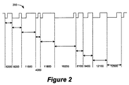
図2は、外部CANバス180上の例示的信号を示す。CCPモジュール140は、CAN信号200の立ち下がりエッジを分析するようにプログラムされる。しかしながら、他の実施形態では、異なる信号特性は、周期を決定するために分析されてもよい。図2によると、立ち下がりエッジが生じるたびに、CCPモジュール140は、タイマモジュールから、タイマ値を捕捉する。捕捉された例示的タイマ値が、示される。値は、単に、この方法の原理の理解を促進するために、小数点以下3桁で四捨五入される。図2に示される実施例では、10の立ち下がりエッジが、調査される。しかしながら、より多いまたはより少ないエッジを処理することができる。捕捉されるエッジが多いほど、自動速度検出は、より精密となるであろう。タイマは、100nsの分解能で初期化されてもよい。この目的を達成するために、タイマは、10MHzまたは任意の他の好適なクロック周波数でクロックされてもよい。タイマ値は、例えば、図1に示されるように、16ビット値であることができる。したがって、クロックソースに応じて、異なる分解能を取得することができる。タイマ分解能が良好であるほど、測定は、より正確となる。最速可能タイマソースの使用は、タイマの分解能を増加させるので、好ましい方法である。例えば、40MHzクロックを使用して、タイマ分解能を25nsまで改善することができる。これらのタイマ値は、次いで、アレイ内に記憶されることができる。
FIG. 2 shows exemplary signals on the
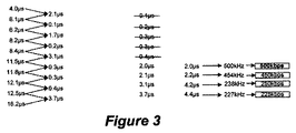
図3は、捕捉されたタイマ値が、どのようにさらに処理されるかを示す。第1のステップでは、10の捕捉されたタイマ値を有するアレイが、最左列に示されるように、最小値から最高値にソートされる。次いで、各2つの隣接するタイマ値の間の差が、第2列に示されるように計算される。次に、異なる差値が、再び、第3列に示されるように、ソートされる。別のステップでは、無効差は、破棄され得る。例えば、明らかに1μsまたは任意の所定の最大周期を下回るか、あるいは所定の最大周波数を上回る値は、図3における第3列に示されるように、破棄され得る。図3における第4列に示されるように、残りの値に対して、残りの周期値に対して結果として生じる周波数が決定される。第1の値は、次いで、CANモジュールの周波数を設定するために使用される。この目的を達成するために、ある実施形態によると、ウィンドウを使用して、周波数をCANシステム内で合理的である最も近い数に丸めてもよい。例えば、263kbpsではなく、250kbpsまたは275kbpsとなる。いったんこの周波数、例えば、図3に示されるように、500kbpsが決定されると、CANモジュール120は、この周波数を使用して、初期化され、正常バストラフィックが中断されないように、「リッスン専用」モードに設定される。次いで、システムは、待機し、受信されたメッセージが有効であるか否か、またはエラーメッセージが、CANモジュールによって生成されるか否かを決定する。エラーメッセージの場合、自動速度検出方法は、図3に示されるように、次の利用可能な周波数、例えば、450kbpsを選択する。これらのステップは、正確な周波数が設定されるまで、繰り返される。したがって、本方法は、図3に示される最後の列において決定されるような異なる周波数を使用して、CANモジュール120を初期化するステップを繰り返す。これらの決定された値のいずれもが正確な設定を生成しない場合、本方法は、再び、開始し、CAN信号の別の10のエッジを評価する。
FIG. 3 shows how the captured timer value is further processed. In the first step, an array with 10 captured timer values is sorted from the smallest value to the highest value, as shown in the leftmost column. The difference between each two adjacent timer values is then calculated as shown in the second column. The different difference values are then sorted again, as shown in the third column. In another step, the invalid difference can be discarded. For example, values that clearly fall below 1 μs or any predetermined maximum period or above a predetermined maximum frequency can be discarded, as shown in the third column in FIG. As shown in the fourth column in FIG. 3, for the remaining values, the resulting frequency is determined for the remaining period values. The first value is then used to set the frequency of the CAN module. To achieve this goal, according to an embodiment, a window may be used to round the frequency to the nearest number that is reasonable within the CAN system. For example, not 263 kbps but 250 kbps or 275 kbps. Once this frequency, eg, 500 kbps, is determined, as shown in FIG. 3, the
図3における第4列に示されるように、タイマ差値は、直接、実際の周波数値を含有するテーブルにアクセスするために使用されてもよい。そのような方法は、容易に、切り捨てまたは丸めを行い、有用周波数値を取得することを可能にするであろう。 As shown in the fourth column in FIG. 3, the timer difference value may be used directly to access a table containing actual frequency values. Such a method would easily allow truncation or rounding to obtain useful frequency values.
図4は、前述の説明された方法の例示的流れ図を示す。ステップ400において、CAN信号は、立ち下がりエッジまたは立ち上がりエッジを検出し、関連付けられたタイマ値t(1)からt(n)までを記憶することによって、CCPモジュールを使用して評価される。これらの値は、次いで、ステップ410において、値ts(1)−ts(n)にソートされる。ステップ420において、Δ値d(1)−d(n−1)は、x=1..n−1に対して、d(x)=ts(x+1)−ts(x)を計算することによって決定される。Δ値は、再び、ステップ430において、ds(1)..ds(n−1)にソートされる。次いで、随意に、ステップ440において、有効周波数を形成しない値ds()は、破棄される。残りの値は、ステップ450において、周波数値f(x)=1/ds(x)を決定するために使用される。ステップ460において、第1の値f(1)は、CANモジュール120を初期化するために使用される。次いで、ステップ470において、フレームが受信される。正確なタイミングは、ステップ480において、CANモジュールが任意のエラーメッセージを生成したか否かをチェックすることによって決定される。そうでない場合、ルーチンは、終了する。エラーが生成された場合、ルーチンは、ステップ490において、例えば、ルックアップテーブルを使用することによって、次の値f(i)を取得することによって進行する。ステップ500において、利用可能な値がないかが決定される。その場合、ルーチンは、ステップ500にジャンプし、そうでなければ、ルーチンは、ステップ460にジャンプする。
FIG. 4 shows an exemplary flow diagram of the previously described method. In
ある実施形態によると、前述の説明されるシーケンスは、ソフトウェアによって行われることができる。しかしながら、別の実施形態によると、状態機械190を使用して、前述のような具体的シーケンスを制御してもよい。図1は、状態機械190を示す。この状態機械は、特に、図1に示されるように、例えば、制御可能ドライバ185を通して、CANバスモジュール120への入力信号を内部で選択可能なマイクロコントローラ100内で有利であろう。状態機械は、特殊機能レジスタ195内でビットを設定するステップを通して始動され得る。いったん始動されると、状態機械190は、ドライバ185を介して、CCPモジュール140に内部CANバス信号を連結し、前述のように、CANモジュール120の初期化を行い、CAN信号をCCPモジュール140から切断する。ユーザは、次いで、他の信号の評価のために、このモジュールを使用してもよい。
According to an embodiment, the above described sequence can be performed by software. However, according to another embodiment, the
本発明は、したがって、目的を遂行し、前述の目標および利点ならびに本明細書に固有のその他を達成するために好適に適応される。本発明は、本発明の特定の好ましい実施形態を参照することによって、描写、説明、および定義されたが、そのような参照は、本発明の限定を含意するものではなく、そのような限定が、暗示されるものでもない。本発明は、当業者に想起されるであろうように、形態および機能に相当な修正、変更、および均等物が可能である。本発明の描写および説明される好ましい実施形態は、例示にすぎず、本発明の範囲の包括ではない。その結果、本発明は、あらゆる観点において、均等物に対する完全認識を与える、添付の請求項の精神および範囲によってのみ限定されることが意図される。 The present invention is therefore suitably adapted to accomplish the objectives and achieve the aforementioned goals and advantages as well as others inherent herein. Although the invention has been described, described and defined with reference to certain preferred embodiments of the invention, such references are not meant to imply limitations on the invention, and such limitations are not to be construed as limiting. It's not even implied. The present invention is capable of considerable modifications, changes and equivalents in form and function, as will occur to those skilled in the art. The depicted and described preferred embodiments of the invention are exemplary only and are not exhaustive of the scope of the invention. As a result, the invention is intended in all respects to be limited only by the spirit and scope of the appended claims, which provides complete recognition for equivalents.
Claims (15)
該方法は、
−コントローラエリアネットワーク信号の連続的な立ち下がりエッジまたは連続的な立ち上がりエッジの間の時間を測定することを含み、
−該測定された時間をソートすることにより、第1のソートされたリストを提供することと、
−該ソートされたリストのうちの隣接する測定された時間の間の差値を決定することと、
−該差値をソートすることにより、第2のソートされたリストを提供することと、
−該第2のソートされたリストから第1の差値を選択し、該第1の差値から第1のビットレート周波数を決定することと、
−該選択されたビットレート周波数を使用して、該コントローラエリアネットワークモジュールを初期化することと、
−コントローラエリアネットワーク信号フレームを受信することと、
−エラーが生じたか否かを決定することと、
−エラーが生じた場合、有効コントローラエリアネットワーク周波数が見つけられるまで、次の周波数を選択し、該コントローラエリアネットワークモジュールを初期化することを繰り返すことと
によって特徴付けられる、方法。 A method for initializing a controller area network module in a microcontroller, comprising:
The method
-Measuring the time between successive falling edges or successive rising edges of the controller area network signal;
Providing a first sorted list by sorting the measured times;
-Determining a difference value between adjacent measured times in the sorted list;
Providing a second sorted list by sorting the difference values;
-Selecting a first difference value from the second sorted list and determining a first bit rate frequency from the first difference value;
Initializing the controller area network module using the selected bit rate frequency;
Receiving a controller area network signal frame;
-Determining whether an error has occurred;
-If an error occurs, the method is characterized by selecting the next frequency and repeating the initialization of the controller area network module until a valid controller area network frequency is found.
無効周波数をもたらす差値を破棄するステップをさらに含む、請求項1に記載の方法。 After the step of sorting the difference values,
The method of claim 1, further comprising discarding difference values that result in invalid frequencies.
該マイクロコントローラは、
中央処理ユニットと、
コントローラエリアネットワークモジュールと、
タイマと、
該タイマと連結された捕捉モジュールと
を備え、
該マイクロコントローラは、請求項1〜11のいずれか一項に記載の方法を行うことによって、コントローラエリアネットワーク周波数を自動的に検出するように構成されている、マイクロコントローラ。 A microcontroller,
The microcontroller
A central processing unit;
A controller area network module;
A timer,
A capture module coupled to the timer,
A microcontroller configured to automatically detect a controller area network frequency by performing the method of any one of claims 1-11.
Applications Claiming Priority (3)
| Application Number | Priority Date | Filing Date | Title |
|---|---|---|---|
| US13/041,535 | 2011-03-07 | ||
| US13/041,535 US9338035B2 (en) | 2011-03-07 | 2011-03-07 | Microcontroller with can bus module and auto speed detect |
| PCT/US2012/026010 WO2012121881A1 (en) | 2011-03-07 | 2012-02-22 | Microcontroller with can bus module and auto speed detect |
Publications (3)
| Publication Number | Publication Date |
|---|---|
| JP2014511068A JP2014511068A (en) | 2014-05-01 |
| JP2014511068A5 JP2014511068A5 (en) | 2015-04-09 |
| JP5963783B2 true JP5963783B2 (en) | 2016-08-03 |
Family
ID=45771950
Family Applications (1)
| Application Number | Title | Priority Date | Filing Date |
|---|---|---|---|
| JP2013557739A Active JP5963783B2 (en) | 2011-03-07 | 2012-02-22 | Microcontroller with CAN bus module and automatic speed detection |
Country Status (7)
| Country | Link |
|---|---|
| US (1) | US9338035B2 (en) |
| EP (1) | EP2684323B1 (en) |
| JP (1) | JP5963783B2 (en) |
| KR (1) | KR101884925B1 (en) |
| CN (1) | CN103416035B (en) |
| TW (1) | TWI537742B (en) |
| WO (1) | WO2012121881A1 (en) |
Cited By (4)
| Publication number | Priority date | Publication date | Assignee | Title |
|---|---|---|---|---|
| US10656025B2 (en) | 2015-06-10 | 2020-05-19 | Ekos Corporation | Ultrasound catheter |
| US10926074B2 (en) | 2001-12-03 | 2021-02-23 | Ekos Corporation | Catheter with multiple ultrasound radiating members |
| US11672553B2 (en) | 2007-06-22 | 2023-06-13 | Ekos Corporation | Method and apparatus for treatment of intracranial hemorrhages |
| US11925367B2 (en) | 2007-01-08 | 2024-03-12 | Ekos Corporation | Power parameters for ultrasonic catheter |
Families Citing this family (8)
| Publication number | Priority date | Publication date | Assignee | Title |
|---|---|---|---|---|
| EP2972926B1 (en) * | 2013-03-12 | 2017-08-23 | Microchip Technology Incorporated | Method and apparatus for clock recovery |
| TWI485407B (en) * | 2013-07-05 | 2015-05-21 | Univ China Sci & Tech | Error Detection Method and System of CAN - BUS Communication Format for Embedded Oscilloscope |
| DE102016214279A1 (en) * | 2016-08-02 | 2018-02-08 | Robert Bosch Gmbh | Method and device for operating a bus system |
| US10615996B2 (en) * | 2018-03-14 | 2020-04-07 | Nxp B.V. | Apparatuses and methods for switching communication modes of a transceiver circuit |
| IT201800003980A1 (en) | 2018-03-26 | 2019-09-26 | Stmicroelectronics Application Gmbh | COMMUNICATION PROCESS, SYSTEM, DEVICES, SIGNAL AND CORRESPONDING VEHICLE |
| US10892911B2 (en) * | 2018-08-28 | 2021-01-12 | Texas Instruments Incorporated | Controller area network receiver |
| WO2020142200A1 (en) * | 2019-01-02 | 2020-07-09 | Exxonmobil Research And Engineering Company | Multi-vehicle data logging device |
| EP3691197B1 (en) * | 2019-01-31 | 2021-12-29 | Nxp B.V. | Bus device and method for operating a bus device |
Family Cites Families (6)
| Publication number | Priority date | Publication date | Assignee | Title |
|---|---|---|---|---|
| JPH0357349A (en) * | 1989-07-26 | 1991-03-12 | Fujitsu Ltd | Line speed detection system |
| US5371766A (en) | 1992-11-20 | 1994-12-06 | International Business Machines Corporation | Clock extraction and data regeneration logic for multiple speed data communications systems |
| SE525273C2 (en) | 2002-01-07 | 2005-01-18 | Kvaser Consultant Ab | Distributed control and monitoring system |
| SE533636C2 (en) * | 2004-10-25 | 2010-11-16 | Xinshu Man L L C | Device for bus connection in CAN system |
| TWI340882B (en) * | 2007-04-09 | 2011-04-21 | Novatek Microelectronics Corp | Real time clock integrated circuit and apparatus thereof |
| JP5064161B2 (en) * | 2007-09-20 | 2012-10-31 | 株式会社オートネットワーク技術研究所 | Electronic control unit |
-
2011
- 2011-03-07 US US13/041,535 patent/US9338035B2/en active Active
-
2012
- 2012-02-21 TW TW101105695A patent/TWI537742B/en active
- 2012-02-22 WO PCT/US2012/026010 patent/WO2012121881A1/en active Application Filing
- 2012-02-22 JP JP2013557739A patent/JP5963783B2/en active Active
- 2012-02-22 KR KR1020137025628A patent/KR101884925B1/en active IP Right Grant
- 2012-02-22 EP EP12706416.0A patent/EP2684323B1/en active Active
- 2012-02-22 CN CN201280012061.9A patent/CN103416035B/en active Active
Cited By (5)
| Publication number | Priority date | Publication date | Assignee | Title |
|---|---|---|---|---|
| US10926074B2 (en) | 2001-12-03 | 2021-02-23 | Ekos Corporation | Catheter with multiple ultrasound radiating members |
| US11925367B2 (en) | 2007-01-08 | 2024-03-12 | Ekos Corporation | Power parameters for ultrasonic catheter |
| US11672553B2 (en) | 2007-06-22 | 2023-06-13 | Ekos Corporation | Method and apparatus for treatment of intracranial hemorrhages |
| US10656025B2 (en) | 2015-06-10 | 2020-05-19 | Ekos Corporation | Ultrasound catheter |
| US11740138B2 (en) | 2015-06-10 | 2023-08-29 | Ekos Corporation | Ultrasound catheter |
Also Published As
| Publication number | Publication date |
|---|---|
| KR101884925B1 (en) | 2018-08-03 |
| CN103416035B (en) | 2016-04-06 |
| JP2014511068A (en) | 2014-05-01 |
| US9338035B2 (en) | 2016-05-10 |
| CN103416035A (en) | 2013-11-27 |
| TW201241637A (en) | 2012-10-16 |
| TWI537742B (en) | 2016-06-11 |
| US20120233341A1 (en) | 2012-09-13 |
| EP2684323A1 (en) | 2014-01-15 |
| EP2684323B1 (en) | 2016-09-14 |
| KR20140014202A (en) | 2014-02-05 |
| WO2012121881A1 (en) | 2012-09-13 |
Similar Documents
| Publication | Publication Date | Title |
|---|---|---|
| JP5963783B2 (en) | Microcontroller with CAN bus module and automatic speed detection | |
| KR100694034B1 (en) | Apparatus for automatic detecting data rate | |
| US10742675B2 (en) | Fraudulent message detection device, electronic control apparatus equipped with fraudulent message detection device, fraudulent message detection method, and fraudulent message detection program | |
| JP6469365B2 (en) | Method for providing general-purpose interface and microcontroller having general-purpose interface | |
| CN110011870B (en) | Node and method for measuring and signal analysis of a multi-master access bus | |
| US11665020B2 (en) | Detecting collisions on a network | |
| US9917705B2 (en) | Device and measuring method for ascertaining the internal delay time of a can bus connection unit | |
| CN110535739B (en) | Slave node for CAN bus network | |
| CN102355395B (en) | Bus communication protocol of fire alarm system | |
| US20210058495A1 (en) | Communication device, communication system, and protocol switchover method | |
| CN112118083A (en) | Single-wire half-duplex communication method, communication device and equipment | |
| JP5892890B2 (en) | Communication control device | |
| JP2008236217A (en) | Flexray network connecting method, flexray network and electronic control unit for flexray network | |
| CN114301991B (en) | Communication method, device, system and computer readable storage medium | |
| US10938507B2 (en) | Communication apparatus | |
| JP2806873B2 (en) | Serial bus communication system | |
| CN216391061U (en) | Gigabit vehicle-mounted Ethernet testing device and system | |
| US11558219B2 (en) | Relay device | |
| JP4031064B2 (en) | Repeater device | |
| EP3139545B1 (en) | Communication interface apparatus | |
| JP5428937B2 (en) | Performance information collection system and performance information collection method | |
| CN110209624A (en) | The data transmission method and system of universal serial bus | |
| CN113890838A (en) | Network connectivity judgment method based on ICMP (Internet control protocol) | |
| JP2014075634A (en) | Communication system, communication speed automatic detector, communication device and communication speed setting method | |
| JP2002135287A (en) | Band limit circuit, communication device, communication network system, and band limiting method |
Legal Events
| Date | Code | Title | Description |
|---|---|---|---|
| A521 | Request for written amendment filed |
Free format text: JAPANESE INTERMEDIATE CODE: A523 Effective date: 20150220 |
|
| A621 | Written request for application examination |
Free format text: JAPANESE INTERMEDIATE CODE: A621 Effective date: 20150220 |
|
| A977 | Report on retrieval |
Free format text: JAPANESE INTERMEDIATE CODE: A971007 Effective date: 20151105 |
|
| A131 | Notification of reasons for refusal |
Free format text: JAPANESE INTERMEDIATE CODE: A131 Effective date: 20151113 |
|
| A601 | Written request for extension of time |
Free format text: JAPANESE INTERMEDIATE CODE: A601 Effective date: 20160212 |
|
| A601 | Written request for extension of time |
Free format text: JAPANESE INTERMEDIATE CODE: A601 Effective date: 20160311 |
|
| A601 | Written request for extension of time |
Free format text: JAPANESE INTERMEDIATE CODE: A601 Effective date: 20160412 |
|
| A521 | Request for written amendment filed |
Free format text: JAPANESE INTERMEDIATE CODE: A523 Effective date: 20160510 |
|
| TRDD | Decision of grant or rejection written | ||
| A01 | Written decision to grant a patent or to grant a registration (utility model) |
Free format text: JAPANESE INTERMEDIATE CODE: A01 Effective date: 20160607 |
|
| A61 | First payment of annual fees (during grant procedure) |
Free format text: JAPANESE INTERMEDIATE CODE: A61 Effective date: 20160628 |
|
| R150 | Certificate of patent or registration of utility model |
Ref document number: 5963783 Country of ref document: JP Free format text: JAPANESE INTERMEDIATE CODE: R150 |
|
| R250 | Receipt of annual fees |
Free format text: JAPANESE INTERMEDIATE CODE: R250 |
|
| R250 | Receipt of annual fees |
Free format text: JAPANESE INTERMEDIATE CODE: R250 |
|
| R250 | Receipt of annual fees |
Free format text: JAPANESE INTERMEDIATE CODE: R250 |
|
| R250 | Receipt of annual fees |
Free format text: JAPANESE INTERMEDIATE CODE: R250 |
|
| R250 | Receipt of annual fees |
Free format text: JAPANESE INTERMEDIATE CODE: R250 |