JP5952247B2 - Radiation imaging apparatus, erasing light source control method and program - Google Patents

Radiation imaging apparatus, erasing light source control method and program Download PDF

Info

Publication number
JP5952247B2
JP5952247B2 JP2013209451A JP2013209451A JP5952247B2 JP 5952247 B2 JP5952247 B2 JP 5952247B2 JP 2013209451 A JP2013209451 A JP 2013209451A JP 2013209451 A JP2013209451 A JP 2013209451A JP 5952247 B2 JP5952247 B2 JP 5952247B2
Authority
JP
Japan
Prior art keywords
radiation
imaging
irradiation
erasing light
light source
Prior art date
Legal status (The legal status is an assumption and is not a legal conclusion. Google has not performed a legal analysis and makes no representation as to the accuracy of the status listed.)
Active
Application number
JP2013209451A
Other languages
Japanese (ja)
Other versions
JP2015073554A (en
Inventor
孝夫 桑原
孝夫 桑原
Current Assignee (The listed assignees may be inaccurate. Google has not performed a legal analysis and makes no representation or warranty as to the accuracy of the list.)
Fujifilm Corp
Original Assignee
Fujifilm Corp
Priority date (The priority date is an assumption and is not a legal conclusion. Google has not performed a legal analysis and makes no representation as to the accuracy of the date listed.)
Filing date
Publication date
Application filed by Fujifilm Corp filed Critical Fujifilm Corp
Priority to JP2013209451A priority Critical patent/JP5952247B2/en
Priority to US14/505,637 priority patent/US9510794B2/en
Priority to CN201410525702.1A priority patent/CN104510484B/en
Publication of JP2015073554A publication Critical patent/JP2015073554A/en
Application granted granted Critical
Publication of JP5952247B2 publication Critical patent/JP5952247B2/en
Active legal-status Critical Current
Anticipated expiration legal-status Critical

Links

Images

Classifications

    • AHUMAN NECESSITIES
    • A61MEDICAL OR VETERINARY SCIENCE; HYGIENE
    • A61BDIAGNOSIS; SURGERY; IDENTIFICATION
    • A61B6/00Apparatus for radiation diagnosis, e.g. combined with radiation therapy equipment
    • A61B6/50Clinical applications
    • A61B6/502Clinical applications involving diagnosis of breast, i.e. mammography
    • AHUMAN NECESSITIES
    • A61MEDICAL OR VETERINARY SCIENCE; HYGIENE
    • A61BDIAGNOSIS; SURGERY; IDENTIFICATION
    • A61B6/00Apparatus for radiation diagnosis, e.g. combined with radiation therapy equipment
    • A61B6/04Positioning of patients; Tiltable beds or the like
    • AHUMAN NECESSITIES
    • A61MEDICAL OR VETERINARY SCIENCE; HYGIENE
    • A61BDIAGNOSIS; SURGERY; IDENTIFICATION
    • A61B6/00Apparatus for radiation diagnosis, e.g. combined with radiation therapy equipment
    • A61B6/02Devices for diagnosis sequentially in different planes; Stereoscopic radiation diagnosis
    • A61B6/025Tomosynthesis
    • AHUMAN NECESSITIES
    • A61MEDICAL OR VETERINARY SCIENCE; HYGIENE
    • A61BDIAGNOSIS; SURGERY; IDENTIFICATION
    • A61B6/00Apparatus for radiation diagnosis, e.g. combined with radiation therapy equipment
    • A61B6/48Diagnostic techniques
    • A61B6/486Diagnostic techniques involving generating temporal series of image data
    • A61B6/487Diagnostic techniques involving generating temporal series of image data involving fluoroscopy
    • AHUMAN NECESSITIES
    • A61MEDICAL OR VETERINARY SCIENCE; HYGIENE
    • A61BDIAGNOSIS; SURGERY; IDENTIFICATION
    • A61B6/00Apparatus for radiation diagnosis, e.g. combined with radiation therapy equipment
    • A61B6/54Control of apparatus or devices for radiation diagnosis
    • GPHYSICS
    • G01MEASURING; TESTING
    • G01TMEASUREMENT OF NUCLEAR OR X-RADIATION
    • G01T1/00Measuring X-radiation, gamma radiation, corpuscular radiation, or cosmic radiation
    • G01T1/16Measuring radiation intensity
    • G01T1/24Measuring radiation intensity with semiconductor detectors
    • G01T1/246Measuring radiation intensity with semiconductor detectors utilizing latent read-out, e.g. charge stored and read-out later
    • AHUMAN NECESSITIES
    • A61MEDICAL OR VETERINARY SCIENCE; HYGIENE
    • A61BDIAGNOSIS; SURGERY; IDENTIFICATION
    • A61B6/00Apparatus for radiation diagnosis, e.g. combined with radiation therapy equipment
    • A61B6/46Apparatus for radiation diagnosis, e.g. combined with radiation therapy equipment with special arrangements for interfacing with the operator or the patient
    • A61B6/461Displaying means of special interest

Description

本発明は、放射線画像撮影装置、消去光源の制御方法およびプログラムに関する。   The present invention relates to a radiographic imaging apparatus, an erasing light source control method, and a program.

乳房のX線撮影を行う放射線検出器(FPD:flat panel detector)を備えたマンモグラフィ装置等の放射線画像撮影装置が知られている。放射線検出器は、変換方式の違いにより直接変換方式と間接変換方式に分けられる。直接変換方式の放射線検出器は、X線情報をアモルファスセレン(a-Se)を用いた光導電層によって直接電気信号に変換する方式である。   2. Description of the Related Art A radiographic imaging apparatus such as a mammography apparatus including a radiation detector (FPD: flat panel detector) that performs X-ray imaging of a breast is known. Radiation detectors are classified into direct conversion methods and indirect conversion methods depending on the conversion method. The direct conversion type radiation detector is a system that converts X-ray information directly into an electrical signal by a photoconductive layer using amorphous selenium (a-Se).

直接変換方式の放射線検出器は、高鮮鋭度と高感度の両立を実現することができる。しかしながら、光導電層にアモルファスセレン(a-Se)を用いた放射線検出器は、光導電層において生じた電荷の輸送遅延に起因して残像が発生しやすいことが指摘されている。この残像を消去するために、放射線検出器に向けて光(以下、消去光という)を照射することにより光導電層内部に光電荷を発生させ、光導電層に残留する残留電荷の消滅を促進させることが行われている。   The direct conversion type radiation detector can realize both high sharpness and high sensitivity. However, it has been pointed out that radiation detectors using amorphous selenium (a-Se) in the photoconductive layer are liable to generate afterimages due to transport delay of charges generated in the photoconductive layer. In order to erase this afterimage, the radiation detector is irradiated with light (hereinafter referred to as erasing light) to generate a photocharge inside the photoconductive layer and promote the disappearance of the residual charge remaining in the photoconductive layer. Has been done.

例えば、特許文献1には、X線管から照射するX線撮影条件を設定する撮影条件設定手段と、X線検出器に残像除去のためのバックライトを照射する光照射部と、光照射部から照射するバックライトの電圧値を設定する電圧値設定手段と、撮影条件設定手段で設定される撮影条件に対応して求められた残像除去に最適なバックライト電圧値を格納した撮影条件―電圧値相関テーブルとを備え、撮影条件に応じて、撮影条件―電圧値相関テーブルから最適なバックライト電圧値を抽出し、電圧値設定手段におけるバックライト電圧値となるように置換し、バックライトを照射することが記載されている。   For example, Patent Document 1 discloses an imaging condition setting unit that sets an X-ray imaging condition irradiated from an X-ray tube, a light irradiation unit that irradiates a backlight for removing an afterimage to an X-ray detector, and a light irradiation unit A voltage value setting unit that sets the voltage value of the backlight that is irradiated from the image capturing condition and voltage that stores the optimal backlight voltage value for afterimage removal determined in accordance with the image capturing condition set by the image capturing condition setting unit A value correlation table is provided, and an optimal backlight voltage value is extracted from the imaging condition-voltage value correlation table according to the imaging conditions, replaced with the backlight voltage value in the voltage value setting means, and the backlight is Irradiation is described.

また、特許文献2には、放射線源から照射された放射線により潜像が形成された輝尽性蛍光体プレートに励起光を照射することによって輝尽光を放出させ、輝尽光に基づき画像情報を読み取った後、輝尽性蛍光体プレートに消去光を照射することによって、残像を消去する放射線画像撮影装置の制御方法において、同一の輝尽性蛍光体プレートで複数回の撮影を行う場合、次の撮影において、輝尽性蛍光体プレートに対して照射される放射線の量を予測して、消去光の照射時間を変更することが記載されている。   Patent Document 2 discloses that stimulating light is emitted by irradiating excitation light to a stimulable phosphor plate on which a latent image is formed by radiation irradiated from a radiation source, and image information based on the stimulation light. In the control method of the radiographic image capturing apparatus for erasing the afterimage by irradiating the stimulable phosphor plate with erasing light after reading, when performing multiple times of imaging with the same stimulable phosphor plate, In the next photographing, it is described that the amount of radiation irradiated to the photostimulable phosphor plate is predicted and the irradiation time of the erasing light is changed.

特開2009−11526号公報JP 2009-11526 A 特開2002−296713号公報JP 2002-296713 A

マンモグラフィ装置においては、放射線を複数の方向から照射することにより取得した複数の投影画像を再構成して断層画像を生成するトモシンセシス撮影機能を搭載した装置が知られている。トモシンセシス撮影においては、放射線の照射角度を順次切り替えながら、複数の投影画像を連続的に撮影する。   As a mammography apparatus, an apparatus equipped with a tomosynthesis imaging function that reconstructs a plurality of projection images acquired by irradiating radiation from a plurality of directions and generates a tomographic image is known. In tomosynthesis imaging, a plurality of projected images are continuously captured while sequentially switching the radiation irradiation angle.

トモシンセシス撮影において、残像消去のために複数回に亘る放射線の照射のタイミングに合わせて消去光の点灯および消灯を繰り返すと画像信号のオフセットが変動し、放射線画像の濃度値が変動してしまうため好ましくない。消去光の点灯によって光導電層において光電荷が発生し、消去光の消灯で光電荷が自然消滅するが、光電荷の発生および消滅は、消去光の点灯および消灯のタイミングに対して遅延する。従って、消去光の点灯および消灯を短周期で繰り返すと光導電層内部の電荷が定常状態とはならず、画像信号のオフセットの変動をもたらす。   In tomosynthesis imaging, it is preferable because the offset of the image signal fluctuates and the density value of the radiographic image fluctuates if the erasing light is repeatedly turned on and off in accordance with the timing of radiation irradiation multiple times to erase the afterimage. Absent. Photoelectric charges are generated in the photoconductive layer when the erasing light is turned on, and the photocharges are spontaneously extinguished when the erasing light is turned off, but the generation and disappearance of the photocharge is delayed with respect to the timing of turning on and off the erasing light. Therefore, if lighting and extinguishing of the erasing light are repeated in a short cycle, the charge inside the photoconductive layer does not become a steady state, and the image signal offset fluctuates.

一方、消去光を点灯させた状態で放射線画像の撮影を行うと放射線画像にムラが生じるという問題がある。消去光を照射することによって光導電層内部に生じる光電荷は、放射線検出器を構成する各層の層厚のゆらぎ等に起因して不均一となる。この光電荷の不均一性が上記のムラの原因となる。1回の放射線の照射時間が比較的短い(例えば100msec程度)トモシンセシス撮影においては、上記のムラが問題となりにくいが、1回の放射線の照射時間がトモシンセシス撮影時の照射時間よりも長い(例えば1〜6sec程度)2D(二次元)撮影においては、上記のムラが顕著となる。   On the other hand, if a radiographic image is taken with the erasing light turned on, there is a problem that unevenness occurs in the radiographic image. The photocharge generated in the photoconductive layer by irradiating the erasing light becomes non-uniform due to fluctuations in the thickness of each layer constituting the radiation detector. This non-uniformity of photocharge causes the above-mentioned unevenness. In tomosynthesis imaging in which the irradiation time of one radiation is relatively short (for example, about 100 msec), the above-described unevenness is unlikely to be a problem, but the irradiation time of one radiation is longer than the irradiation time in tomosynthesis imaging (for example, 1 In the case of 2D (two-dimensional) shooting, the above-mentioned unevenness becomes remarkable.

本発明は、上記した点に鑑みてなされたものであり、放射線の照射時間が比較的短く且つ連続的に放射線画像を撮影する撮影モードと、放射線の照射時間が比較的長い撮影モードの両モードにおいて、従来よりも高画質の放射線画像を得ることができる、放射線画像撮影装置、消去光源の制御方法およびプログラムを提供することを目的とする。   The present invention has been made in view of the above-described points, and is both a shooting mode in which a radiation irradiation time is relatively short and a radiation image is continuously shot, and a shooting mode in which a radiation irradiation time is relatively long. An object of the present invention is to provide a radiographic imaging apparatus, a method for controlling an erasing light source, and a program capable of obtaining a radiographic image with higher image quality than before.

本発明の第1の観点によれば、被写体に向けて放射線を照射する放射線源と、放射線源から照射され被写体を透過した放射線に応じた電荷を発生させるセンサ部を有し、センサ部において生成された電荷を読み出して放射線画像の画像データを生成する放射線検出器と、センサ部に残留する電荷を消去するための消去光を放射線検出器に照射する消去光源と、放射線検出器が、第1の照射時間で放射線源から照射された放射線に基づいて放射線画像の画像データを生成する第1の撮影モードの場合には、少なくとも放射線の照射の開始から放射線検出器による電荷の読み出しの終了までの間、消去光源を消灯状態とし、放射線検出器が、第1の照射時間よりも照射時間の短い第2の照射時間で放射線源から複数回照射された放射線に基づいて複数の放射線画像の画像データを生成する第2の撮影モードの場合には、少なくとも最初の放射線の照射か最後の放射線の照射後の放射線検出器による電荷の読み出しの終了までの間、消去光源を点灯状態とする制御部と、を含む放射線画像撮影装置が提供される。
According to a first aspect of the present invention, there is provided a radiation source that emits radiation toward a subject, and a sensor unit that generates charges according to the radiation emitted from the radiation source and transmitted through the subject. A radiation detector that reads out the generated charges and generates image data of a radiation image, an erasing light source that irradiates the radiation detector with erasing light for erasing charges remaining in the sensor unit, and a radiation detector. In the case of the first imaging mode in which image data of a radiographic image is generated based on the radiation emitted from the radiation source for the irradiation time of at least from the start of radiation irradiation to the end of reading of charges by the radiation detector between, and turned off the erasing light source, a radiation detector, based on a radiation source with a short second irradiation time of the first irradiation time than the irradiation time of the multiple radiations radiation In the second imaging mode to generate image data of the number of radiation images, at least up to the end of the first irradiation morphism or al last radiation the radiation detector by that collector load of read after irradiation of the radiation In the meantime, there is provided a radiographic imaging device including a controller that turns on an erasing light source.

本発明の第2の観点によれば、第2の撮影モードが、放射線源から複数の照射角度で被写体に放射線を照射して複数の放射線画像を連続的に撮影するトモシンセシス撮影モードである第1の観点による放射線画像撮影装置が提供される。
According to a second aspect of the present invention, the second imaging mode is a subject with radiation at a plurality of irradiation angles from the radiation source tomosynthesis imaging mode for continuously shooting a plurality of radiation images shines irradiation A radiographic imaging apparatus according to one aspect is provided.

本発明の第3の観点によれば、第2の撮影モードが、放射線源から所定の時間間隔で被写体に放射線を照射して複数の放射線画像を連続的に撮影する動画撮影モードである第1の観点による放射線画像撮影装置が提供される。
According to a third aspect of the present invention, the second imaging mode is a subject with radiation from the radiation source at predetermined time intervals a moving image shooting mode for continuously shooting a plurality of radiation images shines irradiation A radiographic imaging apparatus according to one aspect is provided.

本発明の第4の観点によれば、第1の撮影モードが、放射線源から所定の照射角度で被写体に放射線を照射して放射線画像を撮影する2D撮影モードである第1乃至第3のいずれかの観点による放射線画像撮影装置が提供される。   According to the fourth aspect of the present invention, any of the first to third modes in which the first imaging mode is a 2D imaging mode in which a subject is irradiated with radiation from a radiation source at a predetermined irradiation angle to capture a radiation image. A radiographic imaging apparatus according to the above viewpoint is provided.

本発明の第5の観点によれば、制御部が、第1の撮影モードにおいて、放射線検出器による電荷の読み出しの終了後に消去光源を点灯状態とする第1乃至第4のいずれかの観点による放射線画像撮影装置が提供される。   According to the fifth aspect of the present invention, according to any one of the first to fourth aspects, the control unit turns on the erasing light source after completion of the charge reading by the radiation detector in the first imaging mode. A radiographic imaging device is provided.

本発明の第6の観点によれば、制御部が第1の撮影モードにおいて、放射線の照射の開始前から消去光源を消灯状態とする1乃至5のいずれかの観点による放射線画像撮影装置が提供される。   According to a sixth aspect of the present invention, there is provided the radiographic image capturing apparatus according to any one of the first to fifth aspects, wherein the control unit turns off the erasing light source before the start of radiation irradiation in the first imaging mode. Is done.

本発明の第7の観点によれば、制御部が、第2の撮影モードにおいて、最初の放射線の照射の開始前から消去光源を点灯状態とする第1乃至第6のいずれかの観点による放射線画像撮影装置が提供される。   According to the seventh aspect of the present invention, the radiation according to any one of the first to sixth aspects in which the control unit turns on the erasing light source before starting the first radiation irradiation in the second imaging mode. An image capture device is provided.

本発明の第8の観点によれば、第1の撮影モードによる撮影と第2の撮影モードによる撮影とを連続して行う第1乃至第7のいずれかの観点による放射線画像撮影装置が提供される。   According to an eighth aspect of the present invention, there is provided a radiographic image capturing apparatus according to any one of the first to seventh aspects, wherein imaging in the first imaging mode and imaging in the second imaging mode are continuously performed. The

本発明の第9の観点によれば、制御部が、第2の撮影モードによる撮影を行った後に第1の撮影モードによる撮影を行う場合には、第2の撮影モードにおいて、放射線検出器による最後の放射線の照射後の電荷の読み出しの終了時に消去光源を消灯状態とする第8の観点による放射線画像撮影装置が提供される。   According to the ninth aspect of the present invention, in the case where the control unit performs imaging in the first imaging mode after performing imaging in the second imaging mode, the control unit uses the radiation detector in the second imaging mode. A radiographic imaging apparatus according to an eighth aspect is provided in which the erasing light source is turned off at the end of reading of charges after the last radiation irradiation.

本発明の第10の観点によれば、制御部が、第1の撮影モードによる撮影を行った後に第2の撮影モードによる撮影を行う場合には、第1の撮影モードにおいて、放射線検出器による電荷の読み出しの終了時に消去光源を点灯状態とする第8の観点による放射線画像撮影装置が提供される。   According to the tenth aspect of the present invention, when the control unit performs imaging in the second imaging mode after performing imaging in the first imaging mode, in the first imaging mode, the control unit uses the radiation detector. A radiographic imaging apparatus according to an eighth aspect is provided in which an erasing light source is turned on at the end of charge reading.

本発明の第11の観点によれば、第1の撮影モードによる撮影と第2の撮影モードによる撮影とを独立して行う第1乃至第7の観点による放射線画像撮影装置が提供される。   According to the 11th viewpoint of this invention, the radiographic imaging apparatus by the 1st thru | or 7th viewpoint which performs imaging | photography by 1st imaging | photography mode and imaging | photography by 2nd imaging | photography mode independently is provided.

本発明の第12の観点によれば、コンピュータを、第1乃至第11のいずれかの観点による放射線画像撮影装置における制御部として機能させるためのプログラムが提供される。   According to a twelfth aspect of the present invention, there is provided a program for causing a computer to function as a control unit in the radiographic imaging apparatus according to any one of the first to eleventh aspects.

本発明の第13の観点によれば、被写体に向けて放射線を照射する放射線源と、放射線源から照射され被写体を透過した放射線に応じた電荷を発生させるセンサ部を有し、センサ部において生成された電荷を読み出して放射線画像の画像データを生成する放射線検出器と、センサ部に残留する電荷を消去するための消去光を放射線検出器に照射する消去光源と、を含む放射線画像撮影装置における消去光源の制御方法であって、放射線検出器が、第1の照射時間で放射線源から照射された放射線に基づいて放射線画像の画像データを生成する第1の撮影モードの場合には、少なくとも放射線の照射の開始から放射線検出器による電荷の読み出しの終了までの間、消去光源を消灯状態とし、放射線検出器が、第1の照射時間よりも照射時間の短い第2の照射時間で放射線源から複数回照射された放射線に基づいて複数の放射線画像の画像データを生成する第2の撮影モードの場合には、少なくとも最初の放射線の照射か最後の放射線の照射後の放射線検出器による電荷の読み出しの終了までの間、消去光源を点灯状態とする制御方法。 According to a thirteenth aspect of the present invention, there is provided a radiation source that emits radiation toward a subject, and a sensor unit that generates charges according to the radiation emitted from the radiation source and transmitted through the subject. In a radiographic imaging apparatus, comprising: a radiation detector that reads out the generated charges and generates image data of a radiation image; and an erasing light source that irradiates the radiation detector with erasing light for erasing charges remaining in the sensor unit In the erasing light source control method, in the first imaging mode in which the radiation detector generates image data of a radiation image based on the radiation irradiated from the radiation source in the first irradiation time, at least radiation between the start of irradiation until the end of the reading of the charges by the radiation detector, and turned off the erasing light source, a radiation detector, a first short irradiation time than irradiation time In the second imaging mode to generate image data of a plurality of radiographic images based on radiation emitted multiple times from the radiation source at a second irradiation time, irradiation morphism or al last radiation of at least the first radiation until the radiation detector end of by that electric load of read after irradiation of a control method of a lighting state of erasing light sources.

本発明によれば、放射線の照射時間が比較的短く且つ連続的に放射線画像を撮影する撮影モードと、放射線の照射時間が比較的長い撮影モードの両モードにおいて、従来よりも高画質の放射線画像を得ることができる。   According to the present invention, in both the imaging mode in which the radiation irradiation time is relatively short and the radiographic image is continuously captured, and the imaging mode in which the radiation irradiation time is relatively long, the radiation image with higher image quality than before. Can be obtained.

本発明の実施形態に係るマンモグラフィ装置の構成を示す斜視図である。It is a perspective view which shows the structure of the mammography apparatus which concerns on embodiment of this invention. 本発明の実施形態に係るマンモグラフィ装置の断面図である。It is sectional drawing of the mammography apparatus which concerns on embodiment of this invention. 本発明の実施形態に係るマンモグラフィ装置におけるトモシンセシス撮影機能を説明するための模式図である。It is a schematic diagram for demonstrating the tomosynthesis imaging | photography function in the mammography apparatus which concerns on embodiment of this invention. 本発明の実施形態に係る放射線検出器の回路図である。It is a circuit diagram of a radiation detector concerning an embodiment of the present invention. 本発明の実施形態に係る放射線検出器の断面図である。It is sectional drawing of the radiation detector which concerns on embodiment of this invention. 本発明の実施形態に係る放射線画像撮影装置のブロック図である。It is a block diagram of a radiographic imaging device concerning an embodiment of the present invention. 本発明の実施形態に係る放射線画像撮影装置の各部の動作タイミングを示すタイミングチャートである。It is a timing chart which shows the operation timing of each part of a radiographic imaging device concerning an embodiment of the present invention. 本発明の実施形態に係る撮影制御プログラムにおける処理の流れを示すフローチャートである。It is a flowchart which shows the flow of a process in the imaging | photography control program which concerns on embodiment of this invention. 本発明の実施形態に係る撮影制御プログラムにおける処理の流れを示すフローチャートである。It is a flowchart which shows the flow of a process in the imaging | photography control program which concerns on embodiment of this invention. 本発明の実施形態に係る放射線画像撮影装置の各部の動作タイミングを示すタイミングチャートである。It is a timing chart which shows the operation timing of each part of a radiographic imaging device concerning an embodiment of the present invention. 本発明の実施形態に係る撮影制御プログラムにおける処理の流れを示すフローチャートであるIt is a flowchart which shows the flow of a process in the imaging | photography control program which concerns on embodiment of this invention. 本発明の実施形態に係る撮影制御プログラムにおける処理の流れを示すフローチャートである。It is a flowchart which shows the flow of a process in the imaging | photography control program which concerns on embodiment of this invention. 図13(a)および図13(b)は、本発明の実施形態に係る放射線画像撮影装置の各部の動作タイミングを示すタイミングチャートである。FIG. 13A and FIG. 13B are timing charts showing the operation timing of each part of the radiographic imaging apparatus according to the embodiment of the present invention. 本発明の実施形態に係る撮影制御プログラムにおける処理の流れを示すフローチャートである。It is a flowchart which shows the flow of a process in the imaging | photography control program which concerns on embodiment of this invention. 本発明の実施形態に係る撮影制御プログラムにおける処理の流れを示すフローチャートであるIt is a flowchart which shows the flow of a process in the imaging | photography control program which concerns on embodiment of this invention. 本発明の実施形態に係る放射線画像撮影装置の各部の動作タイミングを示すタイミングチャートであるIt is a timing chart which shows the operation timing of each part of a radiographic imaging device concerning an embodiment of the present invention. 本発明の実施形態に係る撮影制御プログラムにおける処理の流れを示すフローチャートである。It is a flowchart which shows the flow of a process in the imaging | photography control program which concerns on embodiment of this invention. 本発明の実施形態に係る撮影制御プログラムにおける処理の流れを示すフローチャートである。It is a flowchart which shows the flow of a process in the imaging | photography control program which concerns on embodiment of this invention.

以下、本発明の実施形態に係るマンモグラフィ装置について図面を参照しつつ説明する。なお、各図面において、同一の構成要素には同一の参照符号を付与している。   Hereinafter, a mammography apparatus according to an embodiment of the present invention will be described with reference to the drawings. In the drawings, the same reference numerals are assigned to the same components.

[第1の実施形態]
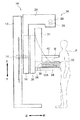
図1は、本発明の実施形態に係る放射線画像撮影装置10の構成の一例を示す斜視図である。図2は、本発明の実施形態に係る放射線画像撮影装置10の左右方向の中心線に沿った断面図である。なお、上下方向、左右方向、前後方向とは、被検者Pである患者から見た方向である。マンモグラフィ装置である放射線画像撮影装置10は、基台部12と、基台部12に設けられたガイド部13に沿って移動可能に設けられた回転軸14と、回転軸14に取り付けられた可動アーム部16とを備えている。可動アーム部16は、回転軸14の移動により上下方向に移動可能に構成されるとともに、回転軸14の回転により左回り及び右回りに回転可能に構成されている。
[First Embodiment]
FIG. 1 is a perspective view showing an example of a configuration of a radiographic image capturing apparatus 10 according to an embodiment of the present invention. FIG. 2 is a cross-sectional view taken along the center line in the left-right direction of the radiographic image capturing apparatus 10 according to the embodiment of the present invention. In addition, the up-down direction, the left-right direction, and the front-rear direction are directions seen from the patient who is the subject P. A radiographic imaging apparatus 10 that is a mammography apparatus includes a base portion 12, a rotary shaft 14 that is movable along a guide portion 13 provided on the base portion 12, and a movable that is attached to the rotary shaft 14. Arm portion 16. The movable arm portion 16 is configured to be movable in the vertical direction by the movement of the rotating shaft 14, and is configured to be able to rotate counterclockwise and clockwise by the rotation of the rotating shaft 14.

可動アーム部16は、回転軸14に固定された第1の回転部18と、回転軸14と切り離し可能に連結された第2の回転部20とを備えている。第2の回転部20は、第1の回転部18よりも被検者P側に配置されている。回転軸14は、第1の回転部18の回転中心に固定されると共に、第2の回転部20の回転中心に連結されている。回転軸14と第2の回転部20とは、例えば、双方にギアが設けられ、第2の回転部20は、ギアが噛み合った状態で回転軸14と連結され、ギアが噛み合っていない状態で回転軸14から切り離される。   The movable arm portion 16 includes a first rotating portion 18 that is fixed to the rotating shaft 14 and a second rotating portion 20 that is detachably connected to the rotating shaft 14. The second rotating unit 20 is disposed closer to the subject P than the first rotating unit 18. The rotation shaft 14 is fixed to the rotation center of the first rotation unit 18 and is connected to the rotation center of the second rotation unit 20. The rotating shaft 14 and the second rotating portion 20 are provided with gears on both sides, for example, and the second rotating portion 20 is connected to the rotating shaft 14 in a state where the gear is engaged, and in a state where the gear is not engaged. It is separated from the rotating shaft 14.

第1の回転部18には、L字状をなす支持部24の一端が固定されている。支持部24の他端には、被検者Pの乳房Mに対し放射線(X線)を照射する放射線照射部28が設けられている。放射線照射部28は、X線管球を含む放射線源26と、後述する主制御部50からの指示に基づく管電圧値、管電流値、照射時間にて放射線を照射するように放射線源26を駆動する放射線源駆動部27(図6参照)と、を備えている。放射線源26は、回転軸14の回転により第1の回転部18とともに回転軸14の周りに回転する。   One end of an L-shaped support portion 24 is fixed to the first rotating portion 18. At the other end of the support part 24, a radiation irradiation part 28 for irradiating the breast M of the subject P with radiation (X-rays) is provided. The radiation irradiation unit 28 controls the radiation source 26 including the X-ray tube and the radiation source 26 so as to irradiate the radiation with a tube voltage value, a tube current value, and an irradiation time based on an instruction from the main control unit 50 described later. And a radiation source driving unit 27 (see FIG. 6) for driving. The radiation source 26 rotates around the rotation axis 14 together with the first rotation unit 18 by the rotation of the rotation axis 14.

第2の回転部20には、圧迫板40を保持する第1の保持部31が取り付けられている。圧迫板40は、第1の保持部31に取り付けられた支持機構42により、上下方向に移動可能に支持されている。圧迫板40が下降することで、被検者Pの乳房Mが圧迫されて、撮影面32Aと圧迫板40との間に固定される。   A first holding unit 31 that holds the compression plate 40 is attached to the second rotating unit 20. The compression plate 40 is supported by a support mechanism 42 attached to the first holding unit 31 so as to be movable in the vertical direction. By lowering the compression plate 40, the breast M of the subject P is compressed and fixed between the imaging surface 32A and the compression plate 40.

第2の回転部20には、撮影台32を保持する第2の保持部34が取り付けられている。また、第2の保持部34には、取っ手46が設けられている。撮影台32は、被検者Pの乳房Mに当接される撮影面32Aを有している。撮影台32の内部には、放射線検出器36および消去光源38が収納されている。   A second holding unit 34 that holds the imaging table 32 is attached to the second rotating unit 20. Further, a handle 46 is provided in the second holding portion 34. The imaging table 32 has an imaging surface 32A that comes into contact with the breast M of the subject P. A radiation detector 36 and an erasing light source 38 are accommodated in the imaging table 32.

放射線検出器36は、放射線源26から照射され、乳房Mを透過した放射線を検出して放射線画像の画像データを生成する直接変換型のFPDである。放射線検出器36の詳細な構成については後述する。   The radiation detector 36 is a direct conversion type FPD that detects radiation emitted from the radiation source 26 and transmitted through the breast M and generates image data of a radiation image. The detailed configuration of the radiation detector 36 will be described later.

消去光源38は、放射線検出器36に対して放射線の照射方向の後方に設けられ、後述する消去光源駆動部39(図6参照)からの駆動信号に応じて放射線検出器36の光導電部に残留する電荷を除去するための消去光を放射線検出器36に照射する。消去光源38は、例えば、光放出面が放射線検出器36の検出面に対して平行に配置された導光板と、導光板の側面に設けられたLED(Light Emitting Diode)等の光源と、を含んで構成されている。なお、消去光源は、LED等の複数の光源を2次元状に配置して構成されていてもよい。   The erasing light source 38 is provided behind the radiation detector 36 in the radiation direction, and is applied to the photoconductive portion of the radiation detector 36 in accordance with a drive signal from an erasing light source driving unit 39 (see FIG. 6) described later. Irradiation light for removing residual charges is irradiated to the radiation detector 36. The erasing light source 38 includes, for example, a light guide plate whose light emission surface is arranged in parallel to the detection surface of the radiation detector 36, and a light source such as an LED (Light Emitting Diode) provided on the side surface of the light guide plate. It is configured to include. The erasing light source may be configured by two-dimensionally arranging a plurality of light sources such as LEDs.

撮影台32に収納された放射線検出器36および消去光源38は、回転軸14と第2の回転部20とが連結された状態で、回転軸14の回転により第2の回転部20と共に回転軸14の周りに回転する。一方、回転軸14と第2の回転部20とが切り離された状態では、回転軸14が回転しても第2の回転部20は回転せず、撮影台32、放射線検出器36及び消去光源38も回転しない。即ち、放射線源26は、放射線検出器36および消去光源38とは、独立に回転可能とされている。   The radiation detector 36 and the erasing light source 38 housed in the imaging table 32 are rotated together with the second rotating unit 20 by the rotation of the rotating shaft 14 in a state where the rotating shaft 14 and the second rotating unit 20 are connected. Rotate around 14. On the other hand, in a state where the rotating shaft 14 and the second rotating portion 20 are separated, even if the rotating shaft 14 rotates, the second rotating portion 20 does not rotate, and the imaging table 32, the radiation detector 36, and the erasing light source. 38 also does not rotate. That is, the radiation source 26 can be rotated independently of the radiation detector 36 and the erasing light source 38.

本実施形態に係る放射線画像撮影装置10は、上述した通り、放射線照射部28及び放射線源26を、撮影台32及び放射線検出器36とは独立に移動できる可動アーム部16を備えている。従って、CC撮影(頭尾方向の撮影)、MLO撮影(内外斜位方向の撮影)、トモシンセシス撮影を含む、種々の撮影モードでの撮影が可能である。   As described above, the radiographic imaging apparatus 10 according to the present embodiment includes the movable arm unit 16 that can move the radiation irradiation unit 28 and the radiation source 26 independently of the imaging table 32 and the radiation detector 36. Therefore, it is possible to shoot in various shooting modes including CC shooting (shooting in the head-to-tail direction), MLO shooting (shooting in the inside / outside oblique direction), and tomosynthesis shooting.

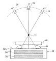
以下に、放射線画像撮影装置10が有するトモシンセシス撮影機能について説明する。図3は、放射線画像撮影装置10におけるトモシンセシス撮影機能を説明するための模式図である。トモシンセシス撮影によれば、被写体である乳房Mに向けて複数の方向から放射線を照射することによって取得された複数の投影画像を用いて乳房Mの断層画像を再構成することができる。   Below, the tomosynthesis imaging | photography function which the radiographic imaging apparatus 10 has is demonstrated. FIG. 3 is a schematic diagram for explaining a tomosynthesis imaging function in the radiographic image capturing apparatus 10. According to tomosynthesis imaging, a tomographic image of the breast M can be reconstructed using a plurality of projection images acquired by irradiating radiation from a plurality of directions toward the subject breast M.

被検者Pの立位状態でのトモシンセシス撮影時には、撮影台32の撮影面32Aが上方を向いた状態に固定しつつ可動アーム部16を回転軸14の周りに回転させることにより複数の照射角度で放射線源26から放射線を照射する。   At the time of tomosynthesis imaging in the standing state of the subject P, a plurality of irradiation angles are obtained by rotating the movable arm unit 16 around the rotation axis 14 while fixing the imaging surface 32A of the imaging table 32 facing upward. Then, the radiation source 26 emits radiation.

可動アーム部16が回転軸14の周りに回転することにより、放射線源26は、図3に示すように、放射線検出器36の上方において円弧を描くように移動する。例えば、正方向の回転の場合には、放射線源26は、角度−X°から角度+X°まで所定の間隔で右周りに回転する。なお、撮影台32の撮影面32A(放射線検出器36の検出面)に対して直交する方向を照射角度0°と定義する。   As the movable arm portion 16 rotates around the rotation axis 14, the radiation source 26 moves in a circular arc above the radiation detector 36, as shown in FIG. For example, in the case of rotation in the positive direction, the radiation source 26 rotates clockwise from the angle −X ° to the angle + X ° at a predetermined interval. A direction orthogonal to the imaging surface 32A of the imaging table 32 (detection surface of the radiation detector 36) is defined as an irradiation angle of 0 °.

トモシンセシス撮影では、乳房Mを圧迫している状態で、可動アーム部16を回転させることにより、放射線検出器36に対する放射線源26の角度位置を移動させ、乳房Mに対して複数の方向から放射線を照射して複数の投影画像を取得する。このようにして取得された複数の投影画像を再構成することにより断層画像が生成される。   In tomosynthesis imaging, while the breast M is being compressed, the movable arm 16 is rotated to move the angular position of the radiation source 26 with respect to the radiation detector 36, so that radiation is emitted from a plurality of directions with respect to the breast M. Irradiate to obtain multiple projected images. A tomographic image is generated by reconstructing a plurality of projection images acquired in this way.

次に、放射線検出器36の構成について説明する。図4は、放射線検出器36の回路図である。放射線検出器36は、放射線の照射によって電荷を発生させるセンサ部100と、センサ部100において発生した電荷を蓄積するキャパシタ210と、キャパシタ210に蓄積された電荷を読み出すためのスイッチ素子(例えばTFT202)とを各々が含む、複数の画素220を有する。複数の画素220は、ガラス基板230上にマトリックス状に配置されている。センサ部100の各々には、図示しない共通配線を介してバイアス電圧が印加されている。なお、放射線検出器36の回路としては、スイッチ素子がTFT型の回路に限定されず、例えばCMOS型を用いた回路でも構わない。   Next, the configuration of the radiation detector 36 will be described. FIG. 4 is a circuit diagram of the radiation detector 36. The radiation detector 36 includes a sensor unit 100 that generates charges by radiation irradiation, a capacitor 210 that accumulates charges generated in the sensor unit 100, and a switch element (for example, TFT 202) for reading out the charges accumulated in the capacitor 210. And each pixel includes a plurality of pixels 220. The plurality of pixels 220 are arranged in a matrix on the glass substrate 230. A bias voltage is applied to each sensor unit 100 via a common wiring (not shown). Note that the circuit of the radiation detector 36 is not limited to a TFT type circuit as a switch element, and may be a circuit using a CMOS type, for example.

ガラス基板230上には、画素220の配列に沿った一定方向(行方向)に伸長し、各TFT202をオンオフさせるためのゲート信号を各TFT202に供給するための複数のゲート線310が設けられている。またガラス基板230上には、ゲート線310の伸長方向と交差する方向(列方向)に伸長し、オン状態のTFT202を介してキャパシタ210に蓄積された電荷を信号処理部340に伝送するための複数の信号線320が設けられている。画素220の各々は、ガラス基板230上において、ゲート線310と信号線320との各交差部に対応して設けられている。   A plurality of gate lines 310 are provided on the glass substrate 230 so as to extend in a certain direction (row direction) along the arrangement of the pixels 220 and supply gate signals for turning on / off each TFT 202 to each TFT 202. Yes. Further, on the glass substrate 230, the charge that extends in the direction (column direction) intersecting with the extension direction of the gate line 310 and is transmitted to the signal processing unit 340 through the on-state TFT 202 is stored in the capacitor 210. A plurality of signal lines 320 are provided. Each pixel 220 is provided on the glass substrate 230 so as to correspond to each intersection of the gate line 310 and the signal line 320.

ゲート線310の各々はゲート線ドライバ330に接続され、信号線320の各々は信号処理部340に接続されている。TFT202は、ゲート線ドライバ330からゲート線310を介して供給されるゲート信号によりオン状態とされる。TFT202がオン状態とされることによりセンサ部100で生成されてキャパシタ210に蓄積された電荷が電気信号として各信号線320に読み出され、信号処理部340に伝送される。信号処理部340は、各信号線320を介して供給される電気信号を処理することによって放射線画像の画像データを生成する。   Each of the gate lines 310 is connected to the gate line driver 330, and each of the signal lines 320 is connected to the signal processing unit 340. The TFT 202 is turned on by a gate signal supplied from the gate line driver 330 via the gate line 310. When the TFT 202 is turned on, the electric charge generated in the sensor unit 100 and accumulated in the capacitor 210 is read as an electric signal to each signal line 320 and transmitted to the signal processing unit 340. The signal processing unit 340 generates image data of a radiographic image by processing an electrical signal supplied via each signal line 320.

FPD制御部350は、放射線画像撮影装置10全体の動作を統括的に制御する後述する主制御部50からの制御信号に基づいて、ゲート線ドライバ330および信号処理部340を制御する。FPD制御部350は、ゲート線ドライバ330および信号処理部340に制御信号を供給することによってゲート線ドライバ330から出力されるゲート信号の出力タイミングを制御するとともに、信号処理部340における信号処理のタイミングを制御する。   The FPD control unit 350 controls the gate line driver 330 and the signal processing unit 340 based on a control signal from a main control unit 50 (described later) that comprehensively controls the operation of the entire radiographic imaging apparatus 10. The FPD control unit 350 controls the output timing of the gate signal output from the gate line driver 330 by supplying control signals to the gate line driver 330 and the signal processing unit 340, and the signal processing timing in the signal processing unit 340. To control.

図5は、放射線検出器36の1画素分の構成を示す断面図である。放射線検出器36は、ガラス基板230と、ガラス基板230上に形成されたTFT202およびキャパシタ210を含む電荷読み出し部200と、電荷読み出し部200上に設けられたセンサ部100とを含む。   FIG. 5 is a cross-sectional view showing the configuration of one pixel of the radiation detector 36. The radiation detector 36 includes a glass substrate 230, a charge readout unit 200 including a TFT 202 and a capacitor 210 formed on the glass substrate 230, and a sensor unit 100 provided on the charge readout unit 200.

TFT202は、ゲート電極203、ゲート絶縁膜204、半導体層205、ソース電極208およびドレイン電極206を含んで構成されている。ゲート電極203はゲート線310(図4参照)に接続され、ソース電極208は信号線320(図4参照)に接続され、ドレイン電極206はキャパシタ210の上部電極213に接続されている。キャパシタ210は、下部電極211、絶縁膜212および上部電極213を積層して構成されている。絶縁膜212はゲート絶縁膜204と一体的に形成され、上部電極213はドレイン電極206と一体的に形成されている。   The TFT 202 includes a gate electrode 203, a gate insulating film 204, a semiconductor layer 205, a source electrode 208 and a drain electrode 206. The gate electrode 203 is connected to the gate line 310 (see FIG. 4), the source electrode 208 is connected to the signal line 320 (see FIG. 4), and the drain electrode 206 is connected to the upper electrode 213 of the capacitor 210. The capacitor 210 is configured by laminating a lower electrode 211, an insulating film 212 and an upper electrode 213. The insulating film 212 is formed integrally with the gate insulating film 204, and the upper electrode 213 is formed integrally with the drain electrode 206.

TFT202およびキャパシタ210を含む電荷読み出し部200上には、層間絶縁膜232を介してセンサ部100が設けられている。センサ部100は、バイアス電極101、電子輸送層102、光導電層103、正孔輸送層104および電荷収集電極105を含んで構成されている。   On the charge reading unit 200 including the TFT 202 and the capacitor 210, the sensor unit 100 is provided via an interlayer insulating film 232. The sensor unit 100 includes a bias electrode 101, an electron transport layer 102, a photoconductive layer 103, a hole transport layer 104, and a charge collection electrode 105.

光導電層103は、X線が照射されることにより電荷を発生させる。光導電層103としては、例えば、暗抵抗が高く、X線に対して良好な電磁波導電性を示し、真空蒸着法により低温で大面積成膜が可能なアモルファスセレン(a-Se)を好適に用いることができる。   The photoconductive layer 103 generates charges when irradiated with X-rays. As the photoconductive layer 103, for example, amorphous selenium (a-Se) having high dark resistance, good electromagnetic wave conductivity with respect to X-rays, and capable of forming a large-area film at a low temperature by a vacuum deposition method is preferably used. Can be used.

光導電層103上には、電子に対しては導電体でありながら正孔の注入を阻止する電子輸送層102が設けられている。電子輸送層102としては、例えばCeO、ZnS、Sb等を好適に用いることができる。 On the photoconductive layer 103, there is provided an electron transport layer 102 that blocks holes while being a conductor for electrons. As the electron transport layer 102, for example, CeO 2 , ZnS, Sb 2 S 3 and the like can be suitably used.

電子輸送層102上には、光導電層103へバイアス電圧を印加するためのバイアス電極101が設けられている。バイアス電極101には、例えば、金(Au)等を用いることが可能である。本実施形態において、バイアス電極101には正電圧が印加される。   A bias electrode 101 for applying a bias voltage to the photoconductive layer 103 is provided on the electron transport layer 102. For the bias electrode 101, for example, gold (Au) or the like can be used. In the present embodiment, a positive voltage is applied to the bias electrode 101.

光導電層103の下方には、正孔に対しては導電体でありながら電子の注入を阻止する正孔輸送層104が設けられている。正孔輸送層104としては、例えばSb、CdS、TeをドープしたSe、CdTe等を好適に用いることができる。 Below the photoconductive layer 103 is provided a hole transport layer 104 that is a conductor for holes but prevents injection of electrons. As the hole transport layer 104, for example, Sb 2 S 3 , CdS, Te-doped Se, CdTe, or the like can be suitably used.

正孔輸送層104の下方には、画素毎に分割された電荷収集電極105が設けられている。電荷収集電極105としては、ITO(Indium-Tin-Oxide)や、IZO(Indium-Zinc-Oxide)等の光透過性を有する導電体を好適に用いることができる。電荷収集電極105は、層間絶縁膜232に形成されたコンタクトホールを介してキャパシタ210の上部電極213に接続されている。   Below the hole transport layer 104, a charge collection electrode 105 divided for each pixel is provided. As the charge collection electrode 105, a light-transmitting conductor such as ITO (Indium-Tin-Oxide) or IZO (Indium-Zinc-Oxide) can be suitably used. The charge collection electrode 105 is connected to the upper electrode 213 of the capacitor 210 through a contact hole formed in the interlayer insulating film 232.

上記した直接変換型の構成を有する放射線検出器36において、バイアス電極101を介してバイアス電圧が印加された光導電層103にX線が入射すると、X線が光導電層103内で吸収されて電子および正孔が生成される。生成された電子および正孔は光導電層103内部に生じている電界に沿って輸送される。正孔は電界によって電荷収集電極105に収集され、キャパシタ210に蓄積される。   In the radiation detector 36 having the direct conversion type configuration described above, when X-rays enter the photoconductive layer 103 to which a bias voltage is applied via the bias electrode 101, the X-rays are absorbed in the photoconductive layer 103. Electrons and holes are generated. The generated electrons and holes are transported along the electric field generated inside the photoconductive layer 103. The holes are collected by the charge collection electrode 105 by an electric field and accumulated in the capacitor 210.

ゲート線ドライバ330からゲート線310を介して供給されるゲート信号によりTFT202がオン状態とされると、キャパシタ210に蓄積された電荷は各信号線320に読み出され、信号処理部340に伝送される。信号処理部340は、各信号線320を介して供給される電気信号に基づいて放射線画像を生成する。   When the TFT 202 is turned on by a gate signal supplied from the gate line driver 330 through the gate line 310, the charge accumulated in the capacitor 210 is read out to each signal line 320 and transmitted to the signal processing unit 340. The The signal processing unit 340 generates a radiation image based on the electrical signal supplied via each signal line 320.

図5には、放射線検出器36とともに消去光源38が示されている。消去光源38は、放射線検出器36のガラス基板230側に配置されている。消去光源38から照射された消去光は、ガラス基板230、電荷読み出し部200および層間絶縁膜232を介して光導電層103に照射される。消去光が光導電層103に照射されることによって光導電層103において光電荷が発生する。光電荷は、光導電層103内部に生じている電界に沿って移動する際に光導電層103内部に残留する残留電荷を消滅させる。これにより、残留電荷に起因する残像が消去される。   FIG. 5 shows an erasing light source 38 together with the radiation detector 36. The erasing light source 38 is disposed on the glass substrate 230 side of the radiation detector 36. The erasing light emitted from the erasing light source 38 is applied to the photoconductive layer 103 through the glass substrate 230, the charge readout unit 200 and the interlayer insulating film 232. By irradiating the photoconductive layer 103 with erasing light, photocharge is generated in the photoconductive layer 103. The photocharge extinguishes the residual charge remaining in the photoconductive layer 103 when moving along the electric field generated in the photoconductive layer 103. Thereby, the afterimage resulting from the residual charge is erased.

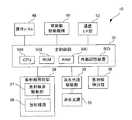
図6は、放射線画像撮影装置10の制御構成を示すブロック図である。放射線画像撮影装置10は、放射線源26および放射線源駆動部27を含む放射線照射部28、放射線検出器36、消去光源38、消去光源駆動部39および操作パネル48を備えている。また、放射線画像撮影装置10は、装置全体の動作を統括的に制御する主制御部50と、撮影時に回転軸14、可動アーム部16及び圧迫板40等の可動部を駆動する可動部駆動機構60と、LAN(Local Area Network)等のネットワークに接続され当該ネットワークに接続された他の機器との間で各種情報を送受信する通信インターフェース部62と、を備えている。   FIG. 6 is a block diagram illustrating a control configuration of the radiographic image capturing apparatus 10. The radiographic imaging apparatus 10 includes a radiation irradiation unit 28 including a radiation source 26 and a radiation source driving unit 27, a radiation detector 36, an erasing light source 38, an erasing light source driving unit 39, and an operation panel 48. The radiographic image capturing apparatus 10 includes a main control unit 50 that comprehensively controls the operation of the entire apparatus, and a movable unit driving mechanism that drives movable units such as the rotating shaft 14, the movable arm unit 16, and the compression plate 40 during imaging. 60, and a communication interface unit 62 that is connected to a network such as a LAN (Local Area Network) and transmits / receives various information to / from other devices connected to the network.

主制御部50は、CPU(Central Processing Unit)50A、ROM(Read Only Memory)50B、RAM(Random Access Memory)50C、HDD(Hard Disk Drive)等の不揮発性の外部記憶装置50Dを備えている。主制御部50は、放射線照射部28、放射線検出器36、消去光源駆動部39、操作パネル48、可動部駆動機構60及び通信インターフェース部62の各々と接続されている。ROM50Bには、CPU50Aが実行する各種プログラムや各種データ等が記憶されている。   The main control unit 50 includes a nonvolatile external storage device 50D such as a CPU (Central Processing Unit) 50A, a ROM (Read Only Memory) 50B, a RAM (Random Access Memory) 50C, and an HDD (Hard Disk Drive). The main control unit 50 is connected to each of the radiation irradiation unit 28, the radiation detector 36, the erasing light source driving unit 39, the operation panel 48, the movable unit driving mechanism 60, and the communication interface unit 62. The ROM 50B stores various programs executed by the CPU 50A, various data, and the like.

放射線源駆動部27、放射線検出器36、消去光源駆動部39および可動部駆動機構60は、主制御部50から供給される制御信号に基づいて動作する。すなわち、放射線源駆動部27は、主制御部50から供給される制御信号に基づいて、所定の管電圧値、管電流値および照射時間にて放射線を照射するように放射線源26を駆動する。放射線検出器36のFPD制御部350は、主制御部50から供給される制御信号に基づいてゲート線ドライバ330および信号処理部340を制御して、センサ部100において生じた電荷の蓄積および読み出しのタイミングを制御する。消去光源駆動部39は、主制御部50から供給される制御信号に基づいて消去光源38の点灯および消灯のタイミングを制御する。可動部駆動機構60は、主制御部50から供給される制御信号に基づいて回転軸14、可動アーム部16及び圧迫板40等の可動部を駆動する。   The radiation source driving unit 27, the radiation detector 36, the erasing light source driving unit 39, and the movable unit driving mechanism 60 operate based on a control signal supplied from the main control unit 50. That is, the radiation source driving unit 27 drives the radiation source 26 so as to irradiate radiation with a predetermined tube voltage value, tube current value, and irradiation time based on a control signal supplied from the main control unit 50. The FPD control unit 350 of the radiation detector 36 controls the gate line driver 330 and the signal processing unit 340 based on the control signal supplied from the main control unit 50, and accumulates and reads out the charges generated in the sensor unit 100. Control timing. The erasing light source driving unit 39 controls the timing of turning on and off the erasing light source 38 based on a control signal supplied from the main control unit 50. The movable part drive mechanism 60 drives the movable parts such as the rotating shaft 14, the movable arm part 16, and the compression plate 40 based on the control signal supplied from the main control part 50.

操作パネル48はユーザの入力操作に応じて選択された撮影モードを示す情報などを主制御部50に通知する。なお、操作パネル48は、放射線画像撮影装置10の一部として設けられていてもよく、放射線画像撮影装置10とは別体の操作卓において放射線画像撮影装置10と通信可能に設けられていてもよい。   The operation panel 48 notifies the main controller 50 of information indicating the shooting mode selected according to the user's input operation. Note that the operation panel 48 may be provided as a part of the radiographic image capturing apparatus 10, or may be provided so as to be able to communicate with the radiographic image capturing apparatus 10 on a separate console from the radiographic image capturing apparatus 10. Good.

以下に、本発明の実施形態に係る放射線画像撮影装置10における放射線画像撮影時の動作について説明する。以下の説明では、互いに異なる複数の照射角度で放射線を連続的に照射して複数の放射線画像を取得するトモシンセシス撮影を行い、トモシンセシス撮影の後、所定の照射角度で放射線を照射して放射線画像を取得する2D(二次元)撮影を行う撮影シーケンスによって一連の放射線画像を取得する場合を例示する。   Below, the operation | movement at the time of the radiographic imaging in the radiographic imaging apparatus 10 which concerns on embodiment of this invention is demonstrated. In the following description, tomosynthesis imaging is performed in which a plurality of radiation images are acquired by continuously irradiating radiation at a plurality of different irradiation angles, and after the tomosynthesis imaging, radiation is irradiated at a predetermined irradiation angle to obtain a radiation image. The case where a series of radiographic images are acquired by the imaging | photography sequence which performs 2D (two-dimensional) imaging | photography acquired is illustrated.

図7は、初めにトモシンセシス撮影を行い、トモシンセシス撮影後に2D撮影を行う場合の放射線画像撮影装置10の各部の動作タイミングを示すタイミングチャートである。図7において、放射線源26から照射される放射線の照射タイミング、放射線検出器36の動作モード、消去光源38の点灯および消灯のタイミングが示されている。また、図7上段の放射線の照射タイミングを示すチャートにおいてハイレベルは放射線の照射に対応し、ローレベルは放射線の非照射に対応する。図7下段の消去光源の点灯および消灯のタイミングを示すチャートにおいてハイレベルは消去光の点灯に対応し、ローレベルは消去光の消灯に対応する(図10、図13および図16において同じ)。   FIG. 7 is a timing chart showing the operation timing of each part of the radiographic imaging apparatus 10 when tomosynthesis imaging is first performed and 2D imaging is performed after tomosynthesis imaging. In FIG. 7, the irradiation timing of the radiation irradiated from the radiation source 26, the operation mode of the radiation detector 36, and the timing of turning on and off the erasing light source 38 are shown. In the chart showing the radiation irradiation timing in the upper part of FIG. 7, a high level corresponds to radiation irradiation, and a low level corresponds to non-irradiation of radiation. In the chart showing the timing of turning on and off the erasing light source in the lower part of FIG. 7, the high level corresponds to lighting of the erasing light, and the low level corresponds to turning off of the erasing light (the same applies to FIGS. 10, 13 and 16).

トモシンセシス撮影において最初の放射線の照射(第1ショット)が開始される前の期間において、放射線検出器36は各画素220のリセットを行う。リセットとは、暗電流によって放射線検出器36のキャパシタ210に蓄積された電荷を、TFT202をオンさせることによって信号線320に排出する処理をいう。リセットモードにおいて、放射線検出器36は、ゲート線ドライバ330から各ゲート線310に順次ゲート信号を出力して各ゲート線310に接続されたTFT202を順次オン状態とすることによってキャパシタ210に蓄積された電荷を排出する。放射線検出器36は、第1ショットの開始前にリセットモードを停止させる。   In the period before the first radiation irradiation (first shot) is started in tomosynthesis imaging, the radiation detector 36 resets each pixel 220. The reset is a process for discharging the charge accumulated in the capacitor 210 of the radiation detector 36 by the dark current to the signal line 320 by turning on the TFT 202. In the reset mode, the radiation detector 36 sequentially outputs gate signals from the gate line driver 330 to each gate line 310 and sequentially turns on the TFTs 202 connected to the respective gate lines 310 to accumulate them in the capacitor 210. Discharge charge. The radiation detector 36 stops the reset mode before the start of the first shot.

また、第1ショットが開始される前のタイミングで、消去光源38は点灯状態に移行する。本実施形態において、消去光源38の点灯が開始されてから第1ショットが開始されるまでの期間tとして1sec以上の時間が確保されている。消去光源38は、トモシンセシス撮影期間中(最終ショットにおける電荷の読み出しの終了まで)、点灯状態を維持する。 Further, at the timing before the first shot is started, the erasing light source 38 shifts to a lighting state. In the present embodiment, a time of 1 sec or more is secured as a period t 1 from the start of lighting of the erasing light source 38 to the start of the first shot. The erasing light source 38 maintains the lighting state during the tomosynthesis imaging period (until the end of charge reading in the final shot).

第1ショットが行われるタイミングで、放射線検出器36は、放射線の照射に伴ってセンサ部100で発生した電荷を各画素220のキャパシタ210に蓄積する蓄積モードに移行する。蓄積モードにおいて、放射線検出器36は、各画素220のTFT202をオフ状態とする。なお、本実施形態において、トモシンセシス撮影における放射線の1回の照射時間(放射線検出器36における電荷蓄積時間)は100msec程度である。放射線の照射時間は被写体に応じて適宜設定することが可能である。   At the timing when the first shot is performed, the radiation detector 36 shifts to an accumulation mode in which charges generated in the sensor unit 100 due to radiation irradiation are accumulated in the capacitor 210 of each pixel 220. In the accumulation mode, the radiation detector 36 turns off the TFT 202 of each pixel 220. In the present embodiment, the irradiation time of one time (charge accumulation time in the radiation detector 36) in tomosynthesis imaging is about 100 msec. The irradiation time of radiation can be appropriately set according to the subject.

放射線の第1ショットが終了するタイミングで、放射線検出器36は、各画素220のキャパシタ210に蓄積された電荷の読み出しを行う読み出しモードに移行する。読み出しモードにおいて、放射線検出器36は、ゲート線ドライバ330から各ゲート線310に順次ゲート信号を出力して各ゲート線310に接続されたTFT202を順次オン状態とする。これにより、キャパシタ210に蓄積された電荷が信号線320に読み出される。読み出された電荷は、信号処理部340に供給され、当該照射角度に対応する放射線画像の画像データが生成される。   At the timing when the first shot of radiation ends, the radiation detector 36 shifts to a readout mode in which the charge accumulated in the capacitor 210 of each pixel 220 is read out. In the readout mode, the radiation detector 36 sequentially outputs gate signals from the gate line driver 330 to the gate lines 310 to sequentially turn on the TFTs 202 connected to the gate lines 310. As a result, the charge accumulated in the capacitor 210 is read out to the signal line 320. The read charge is supplied to the signal processing unit 340, and image data of a radiographic image corresponding to the irradiation angle is generated.

第1ショット後の電荷の読み出しが完了すると、第1ショットとは異なる照射角度で、放射線の2回目の照射(第2ショット)が行われる。放射線検出器36は、第1ショットの場合と同様、放射線の照射開始のタイミングで蓄積モードに移行し、放射線の照射終了のタイミングで読み出しモードに移行する。その後、放射線の照射角度を順次変化させながら、複数回に亘り放射線の照射が行われ、放射線検出器36は放射線の照射タイミングに合わせて電荷の蓄積と読み出しを繰り返す。   When the readout of the charge after the first shot is completed, the second irradiation (second shot) of radiation is performed at an irradiation angle different from that of the first shot. As in the case of the first shot, the radiation detector 36 shifts to the accumulation mode at the timing of the start of radiation irradiation, and shifts to the readout mode at the timing of the end of radiation irradiation. Thereafter, the irradiation of radiation is performed a plurality of times while sequentially changing the irradiation angle of the radiation, and the radiation detector 36 repeats charge accumulation and reading in accordance with the irradiation timing of the radiation.

トモシンセシス撮影における最後の放射線の照射(最終ショット)が行われ、最終ショット後の電荷の読み出しが完了するタイミングで消去光源38は消灯状態に移行する。すなわち、消去光源38は、第1ショットの開始前から最終ショット後の電荷の読み出しが終了するまでの期間に亘り点灯状態を維持する。これにより、各ショットにおいてセンサ部100に生じる残留電荷の消滅が促進され、各ショットにおける残像が消去される。   The last radiation irradiation (final shot) in tomosynthesis imaging is performed, and the erasing light source 38 shifts to an extinguished state at the timing when reading of the charge after the final shot is completed. That is, the erasing light source 38 maintains the lighting state for a period from the start of the first shot to the end of reading of the charge after the final shot. Thereby, the disappearance of the residual charges generated in the sensor unit 100 in each shot is promoted, and the afterimage in each shot is erased.

トモシンセシス撮影が終了すると、放射線検出器36は、リセットモードに移行し、各ゲート線310に接続されたTFT202を順次オン状態とすることによってキャパシタ210に蓄積された電荷を排出する。なお、本実施形態では、トモシンセシス撮影における最終ショット後の電荷の読み出しが完了するタイミングで消去光源38を消灯状態に移行する場合を例示しているが、トモシンセシス撮影終了後のリセット期間中に消去光源38を消灯状態に移行してもよい。   When the tomosynthesis imaging is completed, the radiation detector 36 shifts to the reset mode, and discharges the electric charges accumulated in the capacitor 210 by sequentially turning on the TFTs 202 connected to the gate lines 310. In the present embodiment, the case where the erasing light source 38 shifts to the extinguishing state at the timing when the reading of the charge after the last shot in tomosynthesis imaging is completed is illustrated, but the erasing light source during the reset period after the completion of tomosynthesis imaging 38 may be shifted to a light-off state.

放射線検出器36において各画素220のリセットが完了すると2D撮影に移行する。放射線検出器36は、2D撮影のための放射線の照射が行われるタイミングで蓄積モードに移行する。本実施形態において、トモシンセシス撮影の終了に伴って消去光源38が消灯状態に移行してから2D撮影のための放射線の照射が開始されるまでの期間tとして1sec以上の時間が確保されている。本実施形態において、2D撮影における放射線の1回の照射時間(放射線検出器36における電荷蓄積時間)は、トモシンセシス撮影時における照射時間よりも長く、1〜6sec程度である。放射線の照射時間は、被写体に応じて適宜設定することが可能である。放射線検出器36が2D撮影のための電荷の蓄積を行っている間、消去光源38は消灯状態を維持する。 When the reset of each pixel 220 is completed in the radiation detector 36, the process shifts to 2D imaging. The radiation detector 36 shifts to the accumulation mode at the timing when radiation for 2D imaging is performed. In the present embodiment, 1 sec or longer is ensured as the period t 2 from the erase light source 38 with the end of the tomosynthesis imaging is shifted to OFF state until irradiation for 2D imaging is started . In the present embodiment, the irradiation time of radiation in 2D imaging (charge accumulation time in the radiation detector 36) is longer than the irradiation time in tomosynthesis imaging and is about 1 to 6 seconds. The irradiation time of radiation can be appropriately set according to the subject. While the radiation detector 36 is accumulating charges for 2D imaging, the erasing light source 38 remains off.

2D撮影のための放射線の照射が終了するタイミングで、放射線検出器36は読み出しモードに移行する。これにより2D撮影による放射線画像の画像データが生成される。
放射線検出器36が電荷の読み出しを行っている間、消去光源38は消灯状態を維持する。
At the timing when radiation irradiation for 2D imaging is completed, the radiation detector 36 shifts to a reading mode. Thereby, the image data of the radiographic image by 2D imaging | photography is produced | generated.
While the radiation detector 36 is reading out charges, the erasing light source 38 is kept off.

放射線検出器36は、電荷の読み出しが完了するとリセットモードに移行し、各ゲート線310に接続されたTFT202を順次オン状態とすることによってキャパシタ210に蓄積された電荷を排出する。また、電荷の読み出しが完了するタイミングで消去光源38は点灯状態に移行する。消去光源38は、2D撮影による残像を消去するために十分な期間t(例えば5sec)に亘り点灯状態を維持し、その後消灯状態となる。 The radiation detector 36 shifts to a reset mode when reading of the charges is completed, and discharges the charges accumulated in the capacitor 210 by sequentially turning on the TFTs 202 connected to the gate lines 310. In addition, the erasing light source 38 shifts to a lighting state at the timing when the reading of charges is completed. The erasing light source 38 maintains a lighting state for a period t 3 (for example, 5 sec) sufficient for erasing an afterimage obtained by 2D shooting, and then turns off.

このように、本実施形態に係る放射線画像撮影装置10においては、トモシンセシス撮影モードにおいて放射線の照射角度を切り替えながら複数の放射線画像を連続的に取得している間、消去光源38は点灯状態を維持する。これにより、各放射線画像の撮影において生じる残像を消去することができる。トモシンセシス撮影では、放射線の1回の照射時間が100msec程度と2D撮影の場合(1〜6sec程度)よりも大幅に短いので、消去光を照射した状態で撮影を行っても画像にムラが生じにくい。   As described above, in the radiographic image capturing apparatus 10 according to the present embodiment, the erasing light source 38 maintains the lighting state while acquiring a plurality of radiographic images continuously while switching the radiation angle in the tomosynthesis imaging mode. To do. As a result, afterimages that occur during radiographic image capture can be erased. In tomosynthesis imaging, the time of one irradiation of radiation is about 100 msec, which is much shorter than that in 2D imaging (about 1 to 6 sec), so even if imaging is performed with erasing light applied, image unevenness is unlikely to occur. .

また、複数回に亘る放射線の照射のタイミングに合わせて消去光の点灯および消灯を切り替えることはしないので、放射線検出器36におけるオフセット変動を防止することができる。   Further, since the erasing light is not switched on and off in accordance with the timing of radiation irradiation a plurality of times, the offset fluctuation in the radiation detector 36 can be prevented.

また、トモシンセシス撮影の開始前に消去光源38が点灯状態に移行するので、トモシンセシス撮影の開始時点において、放射線検出器36のセンサ部100内の電荷を定常状態とすることができる。消去光源38が点灯状態または消灯状態に移行してから光導電層103内における電荷が定常状態となるまでには、ある程度の時間を要する。本実施形態においては、消去光源38が点灯状態となってから第1ショットが行われまでの期間tとして1sec以上の時間が確保されているので、蓄積モード移行時において放射線検出器36のセンサ部100内の電荷を定常状態とすることができる。これにより、オフセット変動をさらに効果的に防止することができる。なお、トモシンセシス撮影の開始前に消去光源38を点灯状態に移行すればオフセット変動の抑制の効果が生じるので、期間tとして1secよりも短い期間または長い期間を設定してもよい。 In addition, since the erasing light source 38 shifts to a lighting state before the start of tomosynthesis imaging, the charge in the sensor unit 100 of the radiation detector 36 can be in a steady state at the start of tomosynthesis imaging. A certain amount of time is required until the charge in the photoconductive layer 103 becomes a steady state after the erasing light source 38 shifts to the on state or the off state. In the present embodiment, a time of 1 sec or more is ensured as the period t 1 from when the erasing light source 38 is turned on until the first shot is performed, so that the sensor of the radiation detector 36 during the transition to the accumulation mode The charge in the unit 100 can be in a steady state. Thereby, offset fluctuation can be more effectively prevented. Note that if the erasing light source 38 is shifted to a lighting state before the start of tomosynthesis imaging, an effect of suppressing offset fluctuation is produced. Therefore, a period shorter or longer than 1 sec may be set as the period t 1 .

一方、2D撮影では、放射線の照射時間が1〜6sec程度と比較的長く、2D撮影中に消去光を放射線検出器36に照射すると画像にムラが発生するおそれがある。本実施形態に係る放射線画像撮影装置10においては、2D撮影のための放射線の照射が行われ、放射線検出器36において電荷の蓄積および読み出しを行っている間、消去光源38は消灯状態を維持するので、2D撮影によって取得される放射線画像においてムラの発生を防止することができる。   On the other hand, in 2D imaging, the irradiation time of radiation is relatively long, about 1 to 6 seconds, and if erasing light is applied to the radiation detector 36 during 2D imaging, there is a risk that unevenness will occur in the image. In the radiographic imaging apparatus 10 according to the present embodiment, radiation for 2D imaging is performed, and the erasing light source 38 is kept off while charges are accumulated and read out by the radiation detector 36. Therefore, it is possible to prevent the occurrence of unevenness in the radiographic image acquired by 2D imaging.

また、2D撮影が開始される前に消去光源38が消灯状態に移行するので、2D撮影の開始時点において、放射線検出器36のセンサ部100内の電荷を定常状態とすることができる。本実施形態においては、トモシンセシス撮影の終了後、消去光源38が消灯状態に移行してから2D撮影が開始されるまでの期間tとして1sec以上の時間が確保されている。これにより、2D撮影における蓄積モード移行時に放射線検出器36のセンサ部100内の電荷を定常状態とすることができ、2D撮影においてオフセット変動を防止することができる。なお、2D撮影の開始前に消去光源38を消灯状態に移行すればオフセット変動の抑制の効果が生じるので、期間tとして1secよりも短い期間または長い期間を設定してもよく、トモシンセシス撮影モードから2D撮影モードへの移行期間等を勘案して適宜変更することが可能である。本実施形態のように、トモシンセシス撮影における最終ショット後の電荷の読み出しが完了した時点で消去光源38を消灯状態に移行することで、期間tを最大とすることができる。 In addition, since the erasing light source 38 shifts to the off state before 2D imaging is started, the charge in the sensor unit 100 of the radiation detector 36 can be in a steady state at the start of 2D imaging. In this embodiment, after the end of the tomosynthesis photographing, the erasing light source 38 is 1sec or more time is ensured as the period t 2 from the process proceeds to off state until 2D imaging is started. Thereby, the charge in the sensor unit 100 of the radiation detector 36 can be set to a steady state at the time of transition to the accumulation mode in 2D imaging, and offset fluctuation can be prevented in 2D imaging. Since if transition to off-state of erasing light sources 38 before the start of the 2D imaging the effect of suppressing the offset variation occurs, it may be set shorter period or longer than 1sec as the period t 2, tomosynthesis imaging mode Can be changed as appropriate in consideration of the transition period from the 2D shooting mode to the 2D shooting mode. As in the present embodiment, by moving the erasing light source 38 at the time of reading charges is completed after the final shot off state in the tomosynthesis photographing, it is possible to set the period t 2 to the maximum.

また、2D撮影における電荷の読み出しの終了後、消去光源38が点灯状態となる期間tとして5sec程度の時間が確保されているので、確実に残像を消去することが可能である。なお、期間tとして残像を消去するのに十分な時間が確保されていればよく5secよりも短い時間または長い時間を設定してもよい。また、2D撮影後にセンサ部100に残留する残留電荷を自然消滅させるのに十分な時間が確保されている場合には、2D撮影後における消去光源38の点灯を省略してもよい。 Further, after completion of reading charges in 2D imaging, because the time of about 5sec as the period t 3 when the erasing light source 38 is lit is ensured, it is possible to erase reliably afterimage. It is also possible to set a shorter or longer than 5sec sufficient if sufficient time is secured to erase the afterimage as the period t 3. In addition, when a sufficient time for spontaneously erasing residual charges remaining in the sensor unit 100 after 2D imaging is secured, lighting of the erasing light source 38 after 2D imaging may be omitted.

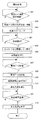
図8および図9は、主制御部50を構成するCPU50Aが実行する撮影制御プログラムにおける処理の流れを示すフローチャートである。撮影制御プログラムは、ROM50Bに格納されている。図8および図9に示すフローチャートは、図7に示すタイミングチャートに対応するものである。なお、撮影制御プログラムの実行開始時点において、消去光源38は消灯状態であるものとする。   FIG. 8 and FIG. 9 are flowcharts showing the flow of processing in the photographing control program executed by the CPU 50 </ b> A constituting the main control unit 50. The photographing control program is stored in the ROM 50B. The flowcharts shown in FIGS. 8 and 9 correspond to the timing chart shown in FIG. It is assumed that the erasing light source 38 is in the off state at the start of execution of the photographing control program.

ステップS11においてCPU50Aは、撮影モード選択指示の受信待ちを行う。ユーザは、操作パネル48を操作することによって、撮影モードの選択を行うことが可能である。ここでは、複数の方向から放射線を連続的に照射して複数の放射線画像を取得するトモシンセシス撮影の後に一方向のみから放射線を照射して単一の放射線画像を取得する2D撮影を行う撮影モードが選択されたものとする。CPU50Aは、撮影モードの選択指示を操作パネル48から受信すると処理をステップS12に移行する。   In step S11, the CPU 50A waits for reception of a shooting mode selection instruction. The user can select a shooting mode by operating the operation panel 48. Here, there is an imaging mode in which 2D imaging is performed in which radiation is irradiated from only one direction to acquire a single radiation image after tomosynthesis imaging in which radiation is continuously irradiated from a plurality of directions to acquire a plurality of radiation images. It shall be selected. When CPU 50A receives an instruction to select a shooting mode from operation panel 48, the process proceeds to step S12.

ステップS12において撮影台に対する乳房Mのポジショニングが行われる。   In step S12, the breast M is positioned with respect to the imaging table.

ステップS13においてCPU50Aは、トモシンセシス撮影の開始の指示がなされたか否かを判定する。ユーザが撮影ボタン(図示せず)を操作する等してトモシンセシス撮影の開始を指示すると、処理はステップS14に移行する。   In step S13, the CPU 50A determines whether or not an instruction to start tomosynthesis imaging has been given. When the user instructs to start tomosynthesis photographing by operating a photographing button (not shown) or the like, the process proceeds to step S14.

ステップS14において、CPU50Aは、可動部駆動機構60に対して可動アーム部16の回転角度位置を初期位置に移動させる制御信号を送信する。CUP50Aからの制御信号を受信した可動部駆動機構60は、例えば、可動アーム部16を傾きの最も大きい回転角度位置(図3に示す−X°の位置)に移動させる。   In step S <b> 14, the CPU 50 </ b> A transmits a control signal for moving the rotational angle position of the movable arm unit 16 to the initial position to the movable unit driving mechanism 60. The movable part drive mechanism 60 that has received the control signal from the CUP 50A, for example, moves the movable arm part 16 to the rotation angle position (position −X ° shown in FIG. 3) having the largest inclination.

ステップS15においてCPU50Aは、消去光源駆動部39に対して消去光の点灯を開始させる制御信号を送信する。CPU50Aからの制御信号を受信した消去光源駆動部39は、消去光源38に駆動信号を供給して消去光源38を点灯状態とする。これにより、放射線検出器36に消去光が照射される。   In step S <b> 15, the CPU 50 </ b> A transmits a control signal for starting lighting of the erasing light to the erasing light source driving unit 39. The erasing light source driving unit 39 that has received the control signal from the CPU 50A supplies a driving signal to the erasing light source 38 to turn on the erasing light source 38. As a result, the radiation detector 36 is irradiated with erasing light.

ステップS16においてCPU50Aは、放射線検出器36のFPD制御部350に放射線の照射準備が完了した旨の通知を行う。放射線検出器36のFPD制御部350は、CUP50Aから放射線の照射準備が完了した旨の通知を受信すると、画素220の各々のキャパシタ210に蓄積された電荷を除去するリセットモードから蓄積モードに移行する。   In step S <b> 16, the CPU 50 </ b> A notifies the FPD control unit 350 of the radiation detector 36 that preparation for radiation irradiation has been completed. When the FPD control unit 350 of the radiation detector 36 receives notification from the CUP 50A that the preparation for radiation irradiation is completed, the FPD control unit 350 shifts from the reset mode that removes the charges accumulated in each capacitor 210 of the pixel 220 to the accumulation mode. .

ステップS17においてCPU50Aは、放射線源駆動部27に対してトモシンセシス撮影のための放射線の照射を開始させる制御信号を供給する。CUP50Aからの制御信号を受信した放射線源駆動部27は、所定の照射条件にて放射線の照射を行うべく放射線源26を駆動する。これにより、放射線源26から乳房Mに向けて放射線が照射される。なお、本ステップにおける放射線の照射時間は100msec程度である。乳房Mを透過した放射線は、放射線検出器36に照射される。放射線検出器36は、放射線の照射タイミングに合わせて蓄積モードおよび読み出しモードに移行し、乳房Mを透過して照射された放射線の線量分布に応じた放射線画像の画像データを生成し、生成した画像データをCPU50Aに送信する。   In step S <b> 17, the CPU 50 </ b> A supplies the radiation source driving unit 27 with a control signal for starting radiation irradiation for tomosynthesis imaging. The radiation source driving unit 27 that has received the control signal from the CUP 50A drives the radiation source 26 to perform radiation irradiation under a predetermined irradiation condition. As a result, radiation is emitted from the radiation source 26 toward the breast M. In addition, the irradiation time of the radiation in this step is about 100 msec. The radiation that has passed through the breast M is applied to the radiation detector 36. The radiation detector 36 shifts to the accumulation mode and the readout mode in accordance with the irradiation timing of the radiation, generates image data of the radiation image corresponding to the dose distribution of the radiation transmitted through the breast M, and the generated image Data is transmitted to the CPU 50A.

ステップS18においてCPU50Aは、放射線検出器36からの画像データの受信待ちを行い、放射線検出器36から画像データを受信すると処理をステップS19に移行する。ステップS19において、CPU50Aは、取得した画像データを外部記憶装置50Dに記憶する。   In step S18, the CPU 50A waits for reception of image data from the radiation detector 36. When image data is received from the radiation detector 36, the process proceeds to step S19. In step S19, the CPU 50A stores the acquired image data in the external storage device 50D.

ステップS20においてCPU50Aは、可動アーム部16の回転角度位置が最終位置(本実施形態では、+X°の位置)にあるか否かを判定し、最終位置にないものと判定した場合には処理をステップS21に移行し、最終位置にあるものと判定した場合には処理をステップS22に移行する。   In step S20, the CPU 50A determines whether or not the rotation angle position of the movable arm portion 16 is at the final position (in this embodiment, the position of + X °). The process proceeds to step S21, and if it is determined that it is at the final position, the process proceeds to step S22.

ステップS21においてCPU50Aは、可動アーム部16の回転角度位置を1段階だけ正方向に移動させる制御信号を可動部駆動機構60に送信する。CPU50Aからの制御信号を受信した可動部駆動機構60は、可動アーム部16の回転角度位置を1段階だけ正方向に移動させる。可動アーム部16の移動が完了すると、CPU50Aは、ステップS17からステップS21までの処理を繰り返し実行する。これにより、可動アーム部16が−X°から+X°まで移動する間に複数回に亘り放射線の照射が行われ、可動アーム部16の各角度位置毎に画像データが取得され、取得された画像データの各々が外部記憶装置50Dに記憶される。   In step S <b> 21, the CPU 50 </ b> A transmits a control signal for moving the rotation angle position of the movable arm unit 16 in the positive direction by one step to the movable unit driving mechanism 60. The movable part drive mechanism 60 that has received the control signal from the CPU 50A moves the rotational angle position of the movable arm part 16 in the positive direction by one step. When the movement of the movable arm unit 16 is completed, the CPU 50A repeatedly executes the processing from step S17 to step S21. Thereby, radiation is performed multiple times while the movable arm unit 16 moves from −X ° to + X °, and image data is acquired for each angular position of the movable arm unit 16, and the acquired image is acquired. Each of the data is stored in the external storage device 50D.

ステップS22においてCPU50Aは、消去光源駆動部39に消去光を消灯させる制御信号を送信する。CPU50Aからの制御信号を受信した消去光源駆動部39は消去光源38を消灯状態とする。以上の各処理を経てトモシンセシス撮影が終了し、2D撮影に移行する。   In step S <b> 22, the CPU 50 </ b> A transmits a control signal for turning off the erasing light to the erasing light source driving unit 39. The erasing light source drive unit 39 that has received the control signal from the CPU 50A turns off the erasing light source 38. Through the above processes, tomosynthesis imaging is completed and the process proceeds to 2D imaging.

ステップS23においてCPU50Aは、可動部駆動機構60に対して可動アーム部16の回転角度位置を2D撮影を行うための所定位置に移動させる制御信号を送信する。CPU50Aからの制御信号を受信した可動部駆動機構60は、可動アーム部16を2D撮影を行うための所定位置に移動させる。2D撮影における可動アーム部16の角度位置として、放射線の照射方向が放射線検出器36の検出面に対して直交する角度位置とすることができる。なお、トモシンセシス撮影における最終ショット時の角度位置にて2D撮影を行ってもよい。この場合、本ステップにおける処理を省略することができる。   In step S <b> 23, the CPU 50 </ b> A transmits a control signal for moving the rotational angle position of the movable arm unit 16 to a predetermined position for performing 2D imaging to the movable unit driving mechanism 60. The movable part drive mechanism 60 that has received the control signal from the CPU 50A moves the movable arm part 16 to a predetermined position for performing 2D imaging. The angular position of the movable arm unit 16 in 2D imaging can be an angular position in which the radiation direction is orthogonal to the detection surface of the radiation detector 36. Note that 2D imaging may be performed at an angular position at the time of the final shot in tomosynthesis imaging. In this case, the process in this step can be omitted.

ステップS24においてCPU50Aは、放射線検出器36のFPD制御部350に2D撮影のための放射線の照射準備が完了した旨の通知を行う。放射線検出器36のFPD制御部350は、CPU50Aから放射線の照射準備が完了した旨の通知を受信すると画素220の各々のキャパシタ210に蓄積された電荷を除去するリセットモードから蓄積モードに移行する。   In step S <b> 24, the CPU 50 </ b> A notifies the FPD control unit 350 of the radiation detector 36 that preparation for radiation irradiation for 2D imaging has been completed. When the FPD control unit 350 of the radiation detector 36 receives notification from the CPU 50A that the preparation for radiation irradiation has been completed, the FPD control unit 350 shifts from the reset mode that removes the charge accumulated in each capacitor 210 of the pixel 220 to the accumulation mode.

ステップS25においてCPU50Aは、放射線源駆動部27に対して2D撮影のための放射線の照射を開始させる制御信号を送信する。CPU50Aからの制御信号を受信した放射線源駆動部27は、所定の照射条件にて放射線の照射を行うべく放射線源26を駆動する。これにより、放射線源26から乳房Mに向けて放射線が照射される。なお、本ステップにおける放射線の照射時間は、トモシンセシス撮影時における照射時間よりも長く、1〜6sec程度である。乳房Mを透過した放射線は、放射線検出器36に照射される。放射線検出器36は、放射線の照射タイミングに合わせて蓄積モードおよび読み出しモードに移行し、乳房Mを透過して照射された放射線の線量分布に応じた放射線画像の画像データを生成し、生成した画像データをCPU50Aに送信する。   In step S <b> 25, the CPU 50 </ b> A transmits a control signal for starting radiation irradiation for 2D imaging to the radiation source driving unit 27. The radiation source driving unit 27 that has received the control signal from the CPU 50A drives the radiation source 26 to perform radiation irradiation under a predetermined irradiation condition. As a result, radiation is emitted from the radiation source 26 toward the breast M. In addition, the irradiation time of the radiation in this step is longer than the irradiation time at the time of tomosynthesis imaging and is about 1 to 6 seconds. The radiation that has passed through the breast M is applied to the radiation detector 36. The radiation detector 36 shifts to the accumulation mode and the readout mode in accordance with the irradiation timing of the radiation, generates image data of the radiation image corresponding to the dose distribution of the radiation transmitted through the breast M, and the generated image Data is transmitted to the CPU 50A.

ステップS26においてCPU50Aは、放射線検出器36からの画像データの受信待ちを行い、放射線検出器36から画像データを受信すると処理をステップS27に移行する。ステップS27において、CPU50Aは、取得した画像データを外部記憶装置50Dに記憶する。   In step S26, the CPU 50A waits for reception of image data from the radiation detector 36. When image data is received from the radiation detector 36, the process proceeds to step S27. In step S27, the CPU 50A stores the acquired image data in the external storage device 50D.

ステップS28においてCPU50Aは、放射線検出器36のFPD制御部350に2D撮影による放射線画像の画像データを適正に受信した旨の通知を行う。放射線検出器36のFPD制御部350は、CPU50Aから画像データが適正に受信された旨の通知を受信すると、画素220の各々のキャパシタ210に蓄積された電荷を除去するリセットモードに移行する。   In step S <b> 28, the CPU 50 </ b> A notifies the FPD control unit 350 of the radiation detector 36 that the image data of the radiation image obtained by 2D imaging has been properly received. When the FPD control unit 350 of the radiation detector 36 receives a notification from the CPU 50A that image data has been properly received, the FPD control unit 350 shifts to a reset mode in which charges accumulated in each capacitor 210 of the pixel 220 are removed.

ステップS29においてCPU50Aは、消去光源駆動部39に消去光の点灯を開始させる制御信号を送信する。CPU50Aからの制御信号を受信した消去光源駆動部39は消去光源38に駆動信号を供給して消去光源38を点灯状態とする。これにより、放射線検出器36に消去光が照射され、放射線検出器36のセンサ部100に残留する残留電荷の消滅が促進され、残像が消去される。   In step S <b> 29, the CPU 50 </ b> A transmits a control signal that causes the erasing light source driving unit 39 to start lighting the erasing light. The erasing light source driving unit 39 that has received the control signal from the CPU 50A supplies a driving signal to the erasing light source 38 to turn on the erasing light source 38. As a result, the radiation detector 36 is irradiated with erasing light, the disappearance of the residual charges remaining in the sensor unit 100 of the radiation detector 36 is promoted, and the afterimage is erased.

ステップS30においてCPU50Aは、消去光源38が点灯状態に移行してから所定時間(例えば5sec)が経過した否か判定し、所定時間が経過したと判定した場合には処理をステップS31に移行する。上記所定時間として、放射線検出器36のセンサ部100に残留する電荷を消滅させるのに十分な時間を適宜設定することが可能である。   In step S30, the CPU 50A determines whether or not a predetermined time (for example, 5 sec) has elapsed since the erasing light source 38 shifted to the lighting state. If it is determined that the predetermined time has elapsed, the process proceeds to step S31. As the predetermined time, it is possible to appropriately set a time sufficient to eliminate the charge remaining in the sensor unit 100 of the radiation detector 36.

ステップS31においてCPU50Aは、消去光源駆動部39に消去光を消灯させる制御信号を送信する。CPU50Aからの制御信号を受信した消去光源駆動部39は消去光源38を消灯状態とする。以上の各処理を経て本ルーチンが終了する。   In step S31, the CPU 50A transmits a control signal for turning off the erasing light to the erasing light source driving unit 39. The erasing light source drive unit 39 that has received the control signal from the CPU 50A turns off the erasing light source 38. This routine is completed through the above processes.

以上の説明から明らかなように、本発明の実施形態に係る放射線画像撮影装置10は、照射角度を変化させながら比較的短い照射時間に亘り放射線を連続的に照射して複数の放射線画像を取得するトモシンセシス撮影を行う場合には、複数の放射線画像を取得する間、消去光源38を継続して点灯させる。このように、複数の放射線画像の撮影タイミングに合わせて消去光の点灯および消灯の切り替えを行うことなくトモシンセシス撮影の開始から終了までの期間に亘り消去光の点灯を維持することで、放射線検出器36におけるオフセット変動を防止することが可能となる。また、トモシンセシス撮影期間中に消去光の点灯を維持することで、各放射線画像の撮影によって放射線検出器36のセンサ部100における残留電荷の消滅を促進させることができ、残像の発生を抑制することができる。トモシンセシス撮影においては、放射線の1回の照射時間は100msec程度と比較的短いので、放射線画像の撮影時(蓄積モード時および読み出しモード時)に消去光を点灯させたとしても当該放射線画像において顕著なムラが発生することはなく、実質的に問題となることはない。   As is clear from the above description, the radiographic imaging apparatus 10 according to the embodiment of the present invention acquires a plurality of radiographic images by continuously irradiating radiation over a relatively short irradiation time while changing the irradiation angle. When performing tomosynthesis imaging, the erasing light source 38 is continuously turned on while a plurality of radiation images are acquired. In this way, the radiation detector is kept on for the period from the start to the end of tomosynthesis imaging without switching the illumination light on and off in accordance with the imaging timing of a plurality of radiographic images. It is possible to prevent the offset fluctuation at 36. Further, by maintaining the erasing light on during the tomosynthesis imaging period, it is possible to promote the disappearance of residual charges in the sensor unit 100 of the radiation detector 36 by imaging each radiographic image, and to suppress the occurrence of an afterimage. Can do. In tomosynthesis imaging, the time of one irradiation of radiation is relatively short, about 100 msec, so that even when erasing light is turned on during radiographic imaging (accumulation mode and readout mode), the radiation image is prominent. Unevenness does not occur, and there is virtually no problem.

一方、放射線画像撮影装置10は、トモシンセシス撮影時における照射時間よりも長い時間に亘り所定の照射角度で放射線を照射して放射線画像を取得する2D撮影を行う場合には、放射線画像を取得する間、消去光源38を消灯させる。これにより、取得される放射線画像においてムラの発生を防止することができる。消去光源38は、2D撮影の終了後(電荷の読み出し後)に点灯状態とされる。これにより、放射線検出器36のセンサ部100における残留電荷の消滅が促進され、残像が消去される。   On the other hand, in the case of performing 2D imaging in which a radiation image is acquired by irradiating radiation at a predetermined irradiation angle for a time longer than the irradiation time at the time of tomosynthesis imaging, the radiographic imaging device 10 acquires a radiographic image. Then, the erasing light source 38 is turned off. Thereby, generation | occurrence | production of a nonuniformity can be prevented in the acquired radiographic image. The erasing light source 38 is turned on after completion of 2D imaging (after reading of charges). Thereby, the disappearance of the residual charge in the sensor unit 100 of the radiation detector 36 is promoted, and the afterimage is erased.

このように、本発明の第1の実施形態に係る放射線画像撮影装置によれば、放射線の照射時間が比較的短く且つ連続的に放射線画像を撮影するトモシンセシス撮影モードと、放射線の照射時間が比較的長い2D撮影モードの両モードにおいて、従来よりも高画質の放射線画像を得ることができる。   As described above, according to the radiographic image capturing apparatus according to the first embodiment of the present invention, the radiation irradiation time is compared with the tomosynthesis imaging mode in which the radiation irradiation time is relatively short and the radiographic image is continuously captured. In both modes of the long 2D imaging mode, a radiographic image with higher image quality than before can be obtained.

[第2の実施形態]
以下に、本発明の第2の実施形態について説明する。第1の実施形態では、互いに異なる照射角度で放射線を連続的に照射して複数の放射線画像を取得するトモシンセシス撮影を行い、トモシンセシス撮影の後に所定の照射角度で放射線を照射して放射線画像を取得する2D撮影を行う撮影シーケンスによって一連の放射線画像を取得する場合を例示した。これに対して、第2の実施形態に係る放射線画像撮影装置10は、初めに2D撮影を行い、2D撮影の後にトモシンセシス撮影を行う撮影シーケンスによって一連の放射線画像を取得する。
[Second Embodiment]
The second embodiment of the present invention will be described below. In the first embodiment, tomosynthesis imaging is performed in which a plurality of radiation images are acquired by continuously irradiating radiation at mutually different irradiation angles, and radiation images are acquired by irradiating radiation at a predetermined irradiation angle after tomosynthesis imaging. A case where a series of radiation images is acquired by an imaging sequence for performing 2D imaging is illustrated. In contrast, the radiographic image capturing apparatus 10 according to the second embodiment first performs 2D imaging, and acquires a series of radiographic images by an imaging sequence in which tomosynthesis imaging is performed after 2D imaging.

図10は、2D撮影後にトモシンセシス撮影を行う場合における放射線画像撮影装置10の各部の動作タイミングを示すタイミングチャートである。   FIG. 10 is a timing chart showing the operation timing of each part of the radiographic imaging device 10 when tomosynthesis imaging is performed after 2D imaging.

2D撮影のための放射線の照射が開始される前の期間においては、放射線検出器36は、各画素220のリセットを行うリセットモードとなる。放射線検出器36は、2D撮影のための放射線の照射の開始前にリセットモードを停止させる。また、2D撮影のための放射線の照射が開始される前の段階から消去光源38は消灯状態とされる。   In a period before radiation irradiation for 2D imaging is started, the radiation detector 36 is in a reset mode in which each pixel 220 is reset. The radiation detector 36 stops the reset mode before starting the irradiation of radiation for 2D imaging. Further, the erasing light source 38 is turned off from the stage before the start of radiation irradiation for 2D imaging.

放射線検出器36において各画素220のリセットが完了すると2D撮影が開始される。2D撮影のための放射線の照射が行われるタイミングで放射線検出器36は、蓄積モードに移行する。また、本実施形態において、2D撮影における放射線の1回の照射時間(放射線検出器36における電荷蓄積時間)は1〜6sec程度である。蓄積期間中、消去光源38は消灯状態を維持する。   When the reset of each pixel 220 is completed in the radiation detector 36, 2D imaging is started. The radiation detector 36 shifts to the accumulation mode at the timing when radiation for 2D imaging is performed. Further, in the present embodiment, a single irradiation time (charge accumulation time in the radiation detector 36) in 2D imaging is about 1 to 6 seconds. During the accumulation period, the erasing light source 38 remains off.

2D撮影のための放射線の照射が終了するタイミングで、放射線検出器36は、読み出しモードに移行する。読み出された電荷は、信号処理部340に供給され、2D撮影に基づく放射線画像の画像データが生成される。2D撮影における電荷の読み出し期間中、消去光源38は消灯状態を維持する。   At the timing when irradiation of radiation for 2D imaging is completed, the radiation detector 36 shifts to a reading mode. The read charges are supplied to the signal processing unit 340, and image data of a radiographic image based on 2D imaging is generated. During the charge readout period in 2D imaging, the erasing light source 38 remains off.

放射線検出器36は、電荷の読み出しが完了するとリセットモードに移行し、各ゲート線310に接続されたTFT202を順次オン状態とすることによってキャパシタ210に蓄積された電荷を排出する。また、電荷の読み出しが完了するタイミングで消去光源38は点灯状態に移行する。消去光源38を点灯状態とすることで2D撮影による残像が消去される。2D撮影による残像を確実に消去するとともに2D撮影に引き続いて実施されるトモシンセシス撮影においてオフセット変動が生じないようにするために、トモシンセシス撮影に移行する前に、可能な限り長い時間に亘り消去光源38を点灯させることが好ましい。本実施形態において、消去光源38の点灯が開始されてからトモシンセシス撮影における最初の放射線の照射(第1ショット)が開始されるまでの期間tとして1sec以上の時間が確保されている。本実施形態では、2D撮影における電荷の読み出しが完了した時点で消去光源38を点灯状態に移行させることにより期間tを最大としている。なお、2D撮影終了後のリセット期間中に消去光源38を点灯状態に移行してもよい。 The radiation detector 36 shifts to a reset mode when reading of the charges is completed, and discharges the charges accumulated in the capacitor 210 by sequentially turning on the TFTs 202 connected to the gate lines 310. In addition, the erasing light source 38 shifts to a lighting state at the timing when the reading of charges is completed. By setting the erasing light source 38 to the lighting state, the afterimage by 2D photographing is erased. In order to reliably erase afterimages caused by 2D imaging and to prevent offset fluctuations in tomosynthesis imaging performed subsequent to 2D imaging, the erasing light source 38 is taken for as long as possible before the shift to tomosynthesis imaging. Is preferably lit. In the present embodiment, 1 sec or more time as the period t 4 to the irradiation of the first radiation (first shot) is started in the lighting tomosynthesis taken from is the start of the erasing light source 38 is ensured. In the present embodiment, the maximum period t 4 by shifting to the lighting state of erasing light sources 38 when the reading of the charges in 2D imaging is completed. Note that the erasing light source 38 may be shifted to a lighting state during a reset period after the end of 2D imaging.

放射線検出器36において各画素220のリセットが完了すると、トモシンセシス撮影に移行する。トモシンセシス撮影において最初の放射線の照射(第1ショット)が行われるタイミングで放射線検出器36は、蓄積モードに移行する。なお、本実施形態において、トモシンセシス撮影における放射線の1回の照射時間は100msec程度である。   When the reset of each pixel 220 is completed in the radiation detector 36, the process shifts to tomosynthesis imaging. The radiation detector 36 shifts to the accumulation mode at the timing when the first radiation irradiation (first shot) is performed in tomosynthesis imaging. In the present embodiment, the time of one irradiation of radiation in tomosynthesis imaging is about 100 msec.

第1ショットが終了するタイミングで、放射線検出器36は、読み出しモードに移行する。読み出された電荷は、信号処理部340に供給され、当該照射角度に対応する放射線画像の画像データが生成される。   At the timing when the first shot ends, the radiation detector 36 shifts to the reading mode. The read charge is supplied to the signal processing unit 340, and image data of a radiographic image corresponding to the irradiation angle is generated.

第1ショット後の電荷の読み出しが完了すると、第1ショットとは異なる照射角度で、放射線の2回目の照射(第2ショット)が行われる。放射線検出器36は、第1ショットの場合と同様、放射線の照射開始のタイミングで蓄積モードに移行し、放射線の照射終了のタイミングで読み出しモードに移行する。その後、放射線の照射角度を順次変化させながら、複数回に亘り放射線の照射が行われ、放射線検出器36は放射線の照射タイミングに合わせて電荷の蓄積と読み出しを繰り返す。   When the readout of the charge after the first shot is completed, the second irradiation (second shot) of radiation is performed at an irradiation angle different from that of the first shot. As in the case of the first shot, the radiation detector 36 shifts to the accumulation mode at the timing of the start of radiation irradiation, and shifts to the readout mode at the timing of the end of radiation irradiation. Thereafter, the irradiation of radiation is performed a plurality of times while sequentially changing the irradiation angle of the radiation, and the radiation detector 36 repeats charge accumulation and reading in accordance with the irradiation timing of the radiation.

放射線検出器36は、最終ショット後の電荷の読み出しが完了するとリセットモードに移行する。また、最終ショット後の電荷の読み出しの完了後、期間tが経過するタイミングで消去光源38は消灯状態に移行する。本実施形態において、期間tは、5sec程度とされており、トモシンセシス撮影による残像を消去するために十分な期間が確保されている。 The radiation detector 36 shifts to the reset mode when reading of the charges after the final shot is completed. Further, after the final shot reading charges after completion, the erasing light source 38 at the timing when the period t 5 elapses shifts to OFF state. In the present embodiment, the period t5 is set to about 5 seconds, and a sufficient period for erasing the afterimage by tomosynthesis imaging is secured.

このように、本実施形態に係る放射線画像撮影装置10においては、第1の実施形態と同様、トモシンセシス撮影において放射線の照射角度を切り替えながら複数の放射線画像を取得している間、消去光源38は点灯状態を維持する。これにより、各放射線画像の撮影において生じる残像を消去することができる。トモシンセシス撮影では、放射線の1回の照射時間が100msec程度と2D撮影の場合(1〜6sec程度)よりも大幅に短いので、消去光を照射した状態で撮影を行っても画像にムラが生じにくい。   As described above, in the radiographic image capturing apparatus 10 according to the present embodiment, the erasing light source 38 is used while acquiring a plurality of radiographic images while switching the radiation irradiation angle in tomosynthesis imaging, as in the first embodiment. Maintain lighting status. As a result, afterimages that occur during radiographic image capture can be erased. In tomosynthesis imaging, the time of one irradiation of radiation is about 100 msec, which is much shorter than that in 2D imaging (about 1 to 6 sec), so even if imaging is performed with erasing light applied, image unevenness is unlikely to occur. .

また、複数回に亘る放射線の照射のタイミングに合わせて消去光の点灯および消灯を切り替えることはしないので、放射線検出器36におけるオフセット変動を防止することができる。   Further, since the erasing light is not switched on and off in accordance with the timing of radiation irradiation a plurality of times, the offset fluctuation in the radiation detector 36 can be prevented.

また、トモシンセシス撮影の開始前に消去光源38が点灯状態に移行するので、トモシンセシス撮影の開始時点において、放射線検出器36のセンサ部100内の電荷を定常状態とすることができる。消去光源38が点灯状態または消灯状態に移行してから光導電層103内における電荷が定常状態となるまでには、ある程度の時間を要する。本実施形態においては、消去光源38が点灯状態となってからトモシンセシス撮影における第1ショットが行われまでの期間tとして1sec以上の時間が確保されているので、蓄積モード移行時において放射線検出器36のセンサ部100内の電荷を定常状態とすることができ、オフセット変動をさらに効果的に防止することができる。なお、トモシンセシス撮影の開始前に消去光源38を点灯状態に移行すればオフセット変動の抑制の効果が生じるので、期間tとして1secよりも短い期間または長い期間を設定することが可能であり、2D撮影モードからトモシンセシス撮影モードへの移行期間等を勘案して適宜変更することが可能である。本実施形態のように、2D撮影における電荷の読み出しが完了した時点で消去光源38を点灯状態に移行することで、期間tを最大とすることができる。 In addition, since the erasing light source 38 shifts to a lighting state before the start of tomosynthesis imaging, the charge in the sensor unit 100 of the radiation detector 36 can be in a steady state at the start of tomosynthesis imaging. A certain amount of time is required until the charge in the photoconductive layer 103 becomes a steady state after the erasing light source 38 shifts to the on state or the off state. In the present embodiment, since the 1sec or more time as the period t 4 from becoming erasing light source 38 is a lighting state until the first shot is performed in tomosynthesis imaging is ensured, the radiation detector during the accumulation mode transition The charge in the 36 sensor units 100 can be in a steady state, and offset fluctuation can be more effectively prevented. Since if transition to the lighting state of erasing light sources 38 before the start of tomosynthesis imaging the effect of suppressing the offset variation occurs, it is possible to set a shorter period or longer than 1sec as the period t 4, 2D It can be changed as appropriate in consideration of the transition period from the imaging mode to the tomosynthesis imaging mode. As in the present embodiment, by moving the lighting state of erasing light sources 38 when the charge of the reading has been completed in 2D imaging, it is possible to maximize the period t 4.

また、トモシンセシス撮影における最終ショット後の電荷の読み出しの終了後、消去光源38が消灯状態に移行するまでの期間tとして5sec程度の時間が確保されているので、確実に残像を消去することが可能である。なお、期間tとして残像を消去するのに十分な時間が確保されていればよく5secよりも短い時間または長い時間を設定してもよい。 Further, after the end of reading of the charge after the final shot in tomosynthesis imaging, a time of about 5 seconds is secured as the period t5 until the erasing light source 38 shifts to the off state, so that the afterimage can be surely erased. Is possible. It is also possible to set a shorter or longer than 5sec sufficient if sufficient time is secured to erase the afterimage as the period t 5.

一方、2D撮影では、放射線の照射時間が1〜6sec程度と比較的長く、撮影期間中に消去光を放射線検出器36に照射すると画像にムラが発生するおそれがある。本実施形態に係る放射線画像撮影装置10においては、2D撮影のための放射線の照射が行われ、放射線検出器36において電荷の蓄積および読み出しを行っている間、消去光源38は消灯状態を維持するので、取得される放射線画像においてムラの発生を防止することができる。   On the other hand, in 2D imaging, the irradiation time of radiation is relatively long, about 1 to 6 seconds, and if the erasing light is applied to the radiation detector 36 during the imaging period, there is a risk that unevenness occurs in the image. In the radiographic imaging apparatus 10 according to the present embodiment, radiation for 2D imaging is performed, and the erasing light source 38 is kept off while charges are accumulated and read out by the radiation detector 36. Therefore, the occurrence of unevenness in the acquired radiographic image can be prevented.

図11および図12は、主制御部50を構成するCPU50Aが実行する第2の実施形態に係る撮影制御プログラムにおける処理の流れを示すフローチャートである。撮影制御プログラムは、ROM50Bに格納されている。図11および図12に示すフローチャートは、図10に示すタイミングチャートに対応するものである。なお、撮影制御プログラムの実行開始時点において、消去光源38は消灯状態であるものとする。   11 and 12 are flowcharts showing the flow of processing in the imaging control program according to the second embodiment executed by the CPU 50A constituting the main control unit 50. The photographing control program is stored in the ROM 50B. The flowcharts shown in FIGS. 11 and 12 correspond to the timing chart shown in FIG. It is assumed that the erasing light source 38 is in the off state at the start of execution of the photographing control program.

ステップS41においてCPU50Aは、撮影モード選択指示の受信待ちを行う。ユーザは、操作パネル48を操作することによって、撮影モードの選択を行うことが可能である。ここでは、一方向のみから放射線を照射して放射線画像を取得する2D撮影の後に複数の方向から放射線を照射して複数の放射線画像を取得するトモシンセシス撮影を行う撮影モードが選択されたものとする。CPU50Aは、撮影モードの選択指示を操作パネル48から受信すると処理をステップS42に移行する。   In step S41, the CPU 50A waits for reception of a shooting mode selection instruction. The user can select a shooting mode by operating the operation panel 48. Here, it is assumed that an imaging mode for performing tomosynthesis imaging in which a plurality of radiation images are acquired by irradiating radiation from a plurality of directions after 2D imaging in which radiation is acquired from only one direction is acquired. . When CPU 50A receives an instruction to select a shooting mode from operation panel 48, the process proceeds to step S42.

ステップS42においてCPU50Aは、可動部駆動機構60に対して可動アーム部16の回転角度位置を2D撮影を行うための所定位置に移動させる制御信号を送信する。CPU50Aからの制御信号を受信した可動部駆動機構60は、例えば、放射線の照射方向が放射線検出器36の検出面に対して直交するように(すなわち照射角度0°となるように)可動アーム部16を移動させる。なお、2D撮影を行う場合の放射線の照射方向を、トモシンセシス撮影における第1ショット時の照射方向と同一としてもよい。   In step S <b> 42, the CPU 50 </ b> A transmits a control signal for moving the rotational angle position of the movable arm unit 16 to a predetermined position for performing 2D imaging to the movable unit driving mechanism 60. The movable part drive mechanism 60 that has received the control signal from the CPU 50A has, for example, the movable arm part so that the radiation direction is orthogonal to the detection surface of the radiation detector 36 (that is, the irradiation angle is 0 °). 16 is moved. Note that the irradiation direction of radiation when performing 2D imaging may be the same as the irradiation direction during the first shot in tomosynthesis imaging.

ステップS43において撮影台に対する乳房Mのポジショニングが行われる。   In step S43, the breast M is positioned with respect to the imaging table.

ステップS44においてCPU50Aは、2D撮影の開始の指示がなされたか否かを判定する。ユーザが撮影ボタン(図示せず)を操作する等して2D撮影の開始を指示すると、処理はステップS45に移行する。   In step S44, the CPU 50A determines whether or not an instruction to start 2D imaging has been issued. When the user instructs the start of 2D shooting, for example, by operating a shooting button (not shown), the process proceeds to step S45.

ステップS45においてCPU50Aは、放射線検出器36のFPD制御部350に放射線の照射準備が完了した旨の通知を行う。放射線検出器36のFPD制御部350は、放射線の照射準備が完了した旨の通知を受信すると、画素220の各々のキャパシタ210に蓄積された電荷を除去するリセットモードから蓄積モードに移行する。   In step S45, the CPU 50A notifies the FPD control unit 350 of the radiation detector 36 that preparation for radiation irradiation has been completed. When the FPD control unit 350 of the radiation detector 36 receives the notification that the preparation for irradiation of radiation has been completed, the FPD control unit 350 shifts from the reset mode that removes the charge accumulated in each capacitor 210 of the pixel 220 to the accumulation mode.

ステップS46においてCPU50Aは、放射線源駆動部27に対して2D撮影のための放射線の照射を開始させる制御信号を送信する。CPU50Aからの制御信号を受信した放射線源駆動部27は、所定の照射条件にて放射線の照射を行うべく放射線源26を駆動する。これにより、放射線源26から乳房Mに向けて放射線が照射される。なお、本ステップにおける放射線の照射時間は1sec程度である。乳房Mを透過した放射線は、放射線検出器36に照射される。放射線検出器36は、放射線の照射タイミングに合わせて蓄積モードおよび読み出しモードに移行し、乳房Mを透過して照射された放射線の線量分布に応じた放射線画像の画像データを生成し、生成した画像データをCPU50Aに送信する。   In step S <b> 46, the CPU 50 </ b> A transmits a control signal for starting radiation irradiation for 2D imaging to the radiation source driving unit 27. The radiation source driving unit 27 that has received the control signal from the CPU 50A drives the radiation source 26 to perform radiation irradiation under a predetermined irradiation condition. As a result, radiation is emitted from the radiation source 26 toward the breast M. In addition, the irradiation time of the radiation in this step is about 1 sec. The radiation that has passed through the breast M is applied to the radiation detector 36. The radiation detector 36 shifts to the accumulation mode and the readout mode in accordance with the irradiation timing of the radiation, generates image data of the radiation image corresponding to the dose distribution of the radiation transmitted through the breast M, and the generated image Data is transmitted to the CPU 50A.

ステップS47においてCPU50Aは、放射線検出器36からの画像データの受信待ちを行い、放射線検出器36から画像データを受信すると処理をステップS48に移行する。ステップS48において、CPU50Aは、取得した画像データを外部記憶装置50Dに記憶する。   In step S47, the CPU 50A waits for reception of image data from the radiation detector 36. When image data is received from the radiation detector 36, the process proceeds to step S48. In step S48, the CPU 50A stores the acquired image data in the external storage device 50D.

ステップS49においてCPU50Aは、放射線検出器36のFPD制御部350に2D撮影おける画像データを適正に受信した旨の通知を行う。放射線検出器36のFPD制御部350は、画像データがCPU50Aにおいて適正に受信された旨の通知を受信すると、画素220の各々のキャパシタ210に蓄積された電荷を除去するリセットモードに移行する。以上の各処理を経て2D撮影が終了し、トモシンセシス撮影に移行する。   In step S49, the CPU 50A notifies the FPD control unit 350 of the radiation detector 36 that the image data for 2D imaging has been properly received. When the FPD control unit 350 of the radiation detector 36 receives a notification that the image data has been properly received by the CPU 50 </ b> A, the FPD control unit 350 shifts to a reset mode in which charges accumulated in each capacitor 210 of the pixel 220 are removed. 2D imaging | photography is complete | finished through the above each process, and it transfers to tomosynthesis imaging | photography.

ステップS50においてCUP50は、消去光源駆動部39に消去光の点灯を開始させる制御信号を送信する。CPU50Aからの制御信号を受信した消去光源駆動部39は消去光源38に駆動信号を供給することにより消去光源38を点灯状態とする。これにより、放射線検出器36に消去光が照射され、放射線検出器36のセンサ部100に残留する残留電荷の消滅が促進され、残像が消去される。   In step S50, the CUP 50 transmits a control signal that causes the erasing light source driving unit 39 to start lighting the erasing light. The erasing light source driving unit 39 that has received the control signal from the CPU 50A supplies the erasing light source 38 with a driving signal to turn on the erasing light source 38. As a result, the radiation detector 36 is irradiated with erasing light, the disappearance of the residual charges remaining in the sensor unit 100 of the radiation detector 36 is promoted, and the afterimage is erased.

ステップS51においてCPU50Aは、可動部駆動機構60に対して可動アーム部16の回転角度位置を初期位置に移動させる制御信号を送信する。CPU50Aからの制御信号を受信した可動部駆動機構60は、例えば、可動アーム部16を傾きの最も大きい回転角度位置(図3に示す−X°の位置)に移動させる。なお、2D撮影を行う場合の可動アーム部16の角度位置が、トモシンセシス撮影における第1ショット時の角度位置と同一である場合には、本ステップにおける処理を省略することができる。撮影準備が完了すると、放射線検出器36はリセットモードから蓄積モードに移行する。   In step S <b> 51, the CPU 50 </ b> A transmits a control signal for moving the rotational angle position of the movable arm unit 16 to the initial position to the movable unit driving mechanism 60. The movable part drive mechanism 60 that has received the control signal from the CPU 50A, for example, moves the movable arm part 16 to the rotation angle position (position −X ° shown in FIG. 3) having the largest inclination. If the angular position of the movable arm 16 when performing 2D imaging is the same as the angular position during the first shot in tomosynthesis imaging, the processing in this step can be omitted. When preparation for imaging is completed, the radiation detector 36 shifts from the reset mode to the accumulation mode.

ステップS52においてCPU50Aは、放射線源駆動部27に対してトモシンセシス撮影のための放射線の照射を開始させる制御信号を送信する。CPU50Aからの制御信号を受信した放射線源駆動部27は、所定の照射条件にて放射線の照射を行うべく放射線源26を駆動する。これにより、放射線源26から乳房Mに向けて放射線が照射される。なお、本ステップにおける放射線の照射時間は100msec程度である。乳房Mを透過した放射線は、放射線検出器36に照射される。放射線検出器36は、放射線の照射タイミングに合わせて蓄積モードおよび読み出しモードに移行し、乳房Mを透過して照射された放射線の線量分布に応じた放射線画像の画像データを生成し、生成した画像データをCPU50Aに送信する。   In step S <b> 52, the CPU 50 </ b> A transmits a control signal for starting irradiation of radiation for tomosynthesis imaging to the radiation source driving unit 27. The radiation source driving unit 27 that has received the control signal from the CPU 50A drives the radiation source 26 to perform radiation irradiation under a predetermined irradiation condition. As a result, radiation is emitted from the radiation source 26 toward the breast M. In addition, the irradiation time of the radiation in this step is about 100 msec. The radiation that has passed through the breast M is applied to the radiation detector 36. The radiation detector 36 shifts to the accumulation mode and the readout mode in accordance with the irradiation timing of the radiation, generates image data of the radiation image corresponding to the dose distribution of the radiation transmitted through the breast M, and the generated image Data is transmitted to the CPU 50A.

ステップS53においてCPU50Aは、放射線検出器36からの画像データの受信待ちを行い、放射線検出器36から画像データを受信すると処理をステップS54に移行する。ステップS54において、CPU50Aは、取得した画像データを外部記憶装置50Dに記憶する。   In step S53, the CPU 50A waits for reception of image data from the radiation detector 36. When image data is received from the radiation detector 36, the process proceeds to step S54. In step S54, the CPU 50A stores the acquired image data in the external storage device 50D.

ステップS55においてCPU50Aは、可動アーム部16の回転角度位置が最終位置(本実施形態では、+X°の位置)にあるか否かを判定し、最終位置にないものと判定した場合には処理をステップS56に移行し、最終位置にあるものと判定した場合には処理をステップS57に移行する。   In step S55, the CPU 50A determines whether or not the rotation angle position of the movable arm portion 16 is at the final position (in this embodiment, the position of + X °). The process proceeds to step S56, and if it is determined that the object is at the final position, the process proceeds to step S57.

ステップS56においてCPU50Aは、可動アーム部16の回転角度位置を1段階だけ正方向に移動させる制御信号を可動部駆動機構60に送信する。CPU50Aからの制御信号を受信した可動部駆動機構60は、可動アーム部16の回転角度位置を1段階だけ正方向に移動させる。可動アーム部16の移動が完了すると、CPU50Aは、ステップS52からステップS56までの処理を繰り返し実行する。これにより、可動アーム部16が−X°から+X°まで移動する間に複数回に亘り放射線の照射が行われ、可動アーム部16の各角度位置毎に画像データが取得され、取得された画像データの各々が外部記憶装置50Dに記憶される。   In step S <b> 56, the CPU 50 </ b> A transmits a control signal for moving the rotational angle position of the movable arm unit 16 in the forward direction by one step to the movable unit driving mechanism 60. The movable part drive mechanism 60 that has received the control signal from the CPU 50A moves the rotational angle position of the movable arm part 16 in the positive direction by one step. When the movement of the movable arm unit 16 is completed, the CPU 50A repeatedly executes the processing from step S52 to step S56. Thereby, radiation is performed multiple times while the movable arm unit 16 moves from −X ° to + X °, and image data is acquired for each angular position of the movable arm unit 16, and the acquired image is acquired. Each of the data is stored in the external storage device 50D.

ステップS57においてCPU50Aは、放射線検出器36のFPD制御部350にトモシンセシス撮影における全ての画像データを適正に受信した旨の通知を行う。放射線検出器36のFPD制御部350は、かかる通知を受信すると画素220の各々をリセットし、キャパシタ210に蓄積された電荷を除去する。   In step S57, the CPU 50A notifies the FPD control unit 350 of the radiation detector 36 that all image data in tomosynthesis imaging has been properly received. When receiving the notification, the FPD control unit 350 of the radiation detector 36 resets each of the pixels 220 and removes the electric charge accumulated in the capacitor 210.

ステップS58においてCPU50Aは、消去光源駆動部39に消去光を消灯させる制御信号を送信する。CPU50Aからの制御信号を受信した消去光源駆動部39は消去光源38を消灯状態とする。以上の各処理を経て本ルーチンが終了する。   In step S58, the CPU 50A transmits a control signal for turning off the erasing light to the erasing light source driving unit 39. The erasing light source drive unit 39 that has received the control signal from the CPU 50A turns off the erasing light source 38. This routine is completed through the above processes.

このように、本発明の第2の実施形態に係る放射線画像撮影装置によれば、第1の実施形態と同様、放射線の照射時間が比較的短く且つ連続的に複数の放射線画像を撮影するトモシンセシス撮影モードにおいて複数の放射線画像を取得する間、消去光源38を継続して点灯させ、放射線の照射時間が比較的長い2D撮影モードにおいて放射線画像を取得する間、消去光源38を消灯させる。従って、トモシンセシス撮影モードと2D撮影モードの両モードにおいて、従来よりも高画質の放射線画像を得ることができる。   As described above, according to the radiographic image capturing apparatus according to the second embodiment of the present invention, as in the first embodiment, the tomosynthesis that captures a plurality of radiographic images continuously with a relatively short radiation time. The erasing light source 38 is continuously turned on while a plurality of radiation images are acquired in the imaging mode, and the erasing light source 38 is turned off while the radiation image is acquired in the 2D imaging mode in which the radiation irradiation time is relatively long. Therefore, in both the tomosynthesis imaging mode and the 2D imaging mode, a radiographic image with higher image quality than before can be obtained.

[第3の実施形態]
以下に、本発明の第3の実施形態について説明する。第1および第2の実施形態では、トモシンセシス撮影と2D撮影とを連続して行う場合を例示した。これに対して第3の実施形態に係る放射線画像撮影装置10は、トモシンセシス撮影および2D撮影をそれぞれ単独で行う。
[Third Embodiment]
The third embodiment of the present invention will be described below. In the first and second embodiments, the case where tomosynthesis imaging and 2D imaging are continuously performed is illustrated. On the other hand, the radiographic image capturing apparatus 10 according to the third embodiment independently performs tomosynthesis imaging and 2D imaging.

図13(a)は、2D撮影を単独で行う場合の放射線画像撮影装置10の各部の動作タイミングを示すタイミングチャートである。図13(b)は、トモシンセシス撮影を単独で行う場合の放射線画像撮影装置10の各部の動作タイミングを示すタイミングチャートである。   FIG. 13A is a timing chart showing the operation timing of each part of the radiographic image capturing apparatus 10 when performing 2D imaging alone. FIG. 13B is a timing chart showing the operation timing of each part of the radiographic image capturing apparatus 10 when tomosynthesis imaging is performed alone.

2D撮影のための放射線の照射が開始される前の期間において、放射線検出器36は、各画素220のリセットを行うリセットモードとなる。放射線検出器36は、2D撮影のための放射線の照射の開始前にリセットモードを停止させる。また、2D撮影のための放射線の照射が開始される前の段階から消去光源38は消灯状態とされる。   In a period before radiation irradiation for 2D imaging is started, the radiation detector 36 is in a reset mode in which each pixel 220 is reset. The radiation detector 36 stops the reset mode before starting the irradiation of radiation for 2D imaging. Further, the erasing light source 38 is turned off from the stage before the start of radiation irradiation for 2D imaging.

放射線検出器36において各画素220のリセットが完了すると2D撮影が開始される。2D撮影のための放射線の照射が行われるタイミングで放射線検出器36は、蓄積モードに移行する。また、本実施形態において、2D撮影における放射線の1回の照射時間(放射線検出器36における電荷蓄積時間)は1〜6sec程度である。蓄積期間中、消去光源38は消灯状態を維持する。   When the reset of each pixel 220 is completed in the radiation detector 36, 2D imaging is started. The radiation detector 36 shifts to the accumulation mode at the timing when radiation for 2D imaging is performed. Further, in the present embodiment, a single irradiation time (charge accumulation time in the radiation detector 36) in 2D imaging is about 1 to 6 seconds. During the accumulation period, the erasing light source 38 remains off.

2D撮影のための放射線の照射が終了するタイミングで、放射線検出器36は読み出しモードに移行する。読み出された電荷は、信号処理部340に供給され、2D撮影に基づく放射線画像の画像データが生成される。2D撮影における電荷の読み出し期間中、消去光源38は消灯状態を維持する。   At the timing when radiation irradiation for 2D imaging is completed, the radiation detector 36 shifts to a reading mode. The read charges are supplied to the signal processing unit 340, and image data of a radiographic image based on 2D imaging is generated. During the charge readout period in 2D imaging, the erasing light source 38 remains off.

放射線検出器36は、電荷の読み出しが完了するとリセットモードに移行し、各ゲート線310に接続されたTFT202を順次オン状態とすることによってキャパシタ210に蓄積された電荷を排出する。また、電荷の読み出しが完了するタイミングで消去光源38は点灯状態に移行する。本実施形態において、消去光源38の点灯期間tは、5secとされており、2D撮影による残像の消去に十分な時間が確保されている。 The radiation detector 36 shifts to a reset mode when reading of the charges is completed, and discharges the charges accumulated in the capacitor 210 by sequentially turning on the TFTs 202 connected to the gate lines 310. In addition, the erasing light source 38 shifts to a lighting state at the timing when the reading of charges is completed. In the present embodiment, the lighting period t 6 of the erasing light source 38 is a 5 sec, sufficient time is ensured to erase the afterimage by 2D imaging.

次に、トモシンセシス撮影を単独で行う場合について図13(b)を参照しつつ説明する。   Next, a case where tomosynthesis imaging is performed alone will be described with reference to FIG.

トモシンセシス撮影において最初の放射線の照射(第1ショット)の開始前に、放射線検出器36は各画素220のリセットを行うリセットモードを停止させる。   In the tomosynthesis imaging, the radiation detector 36 stops the reset mode in which each pixel 220 is reset before the start of the first radiation irradiation (first shot).

また、最初の放射線の照射(第1ショット)が開始される前のタイミングで、消去光源38は点灯状態に移行する。本実施形態において、消去光源38の点灯が開始されてから第1ショットが開始されるまでの期間tとして1sec以上の時間が確保されている。消去光源38は、トモシンセシス撮影期間中、点灯状態を維持する。 Further, at the timing before the first radiation irradiation (first shot) is started, the erasing light source 38 shifts to a lighting state. In the present embodiment, the 1sec or more time as the period t 7 from when the lighting of the erasing light source 38 is started until the first shot is started is ensured. The erasing light source 38 is kept on during the tomosynthesis imaging period.

第1ショットが行われるタイミングで、放射線検出器36は、蓄積モードに移行する。なお、本実施形態において、トモシンセシス撮影における放射線の1回の照射時間(放射線検出器36における電荷蓄積時間)は100msec程度である。   At the timing when the first shot is performed, the radiation detector 36 shifts to the accumulation mode. In the present embodiment, the irradiation time of one time (charge accumulation time in the radiation detector 36) in tomosynthesis imaging is about 100 msec.

第1ショットが終了するタイミングで、放射線検出器36は読み出しモードに移行し、当該照射角度に対応する放射線画像の画像データが生成される。   At the timing when the first shot ends, the radiation detector 36 shifts to the reading mode, and image data of a radiation image corresponding to the irradiation angle is generated.

第1ショット後の電荷の読み出しが完了すると、第1ショットとは異なる照射角度で、放射線の2回目の照射(第2ショット)が行われる。放射線検出器36は、第1ショットの場合と同様、放射線の照射開始のタイミングで蓄積モードに移行し、放射線の照射終了のタイミングで読み出しモードに移行する。その後、放射線の照射角度を順次変化させながら、複数回に亘り放射線の照射が行われ、放射線検出器36は放射線の照射タイミングに合わせて電荷の蓄積と読み出しを繰り返す。   When the readout of the charge after the first shot is completed, the second irradiation (second shot) of radiation is performed at an irradiation angle different from that of the first shot. As in the case of the first shot, the radiation detector 36 shifts to the accumulation mode at the timing of the start of radiation irradiation, and shifts to the readout mode at the timing of the end of radiation irradiation. Thereafter, the irradiation of radiation is performed a plurality of times while sequentially changing the irradiation angle of the radiation, and the radiation detector 36 repeats charge accumulation and reading in accordance with the irradiation timing of the radiation.

放射線検出器36は、最終ショット後の電荷の読み出しが完了すると、リセットモードに移行する。また、最終ショット後の電荷の読み出しの終了後、期間tが経過するタイミングで消去光源38は消灯状態に移行する。本実施形態において、期間tは、5sec程度とされており、トモシンセシス撮影による残像を消去するために十分な期間が確保されている。 The radiation detector 36 shifts to the reset mode when reading of the charge after the final shot is completed. Further, after the reading charges after the last shot finished, the erasing light source 38 at the timing when the period t 8 has elapsed shifts to OFF state. In the present embodiment, the period t 8 is about 5 sec, has sufficient time to erase the afterimage by tomosynthesis imaging is ensured.

このように、本実施形態に係る放射線画像撮影装置10においては、第1および第2の実施形態と同様、トモシンセシス撮影において放射線の照射角度を切り替えながら複数の放射線画像を取得している間、消去光源38は点灯状態を維持する。これにより、各放射線画像の撮影において生じる残像を消去することができる。トモシンセシス撮影では、放射線の1回の照射時間が100msec程度と2D撮影の場合(1〜6sec程度)よりも大幅に短いので、消去光を照射した状態で撮影を行っても画像にムラが生じにくい。   As described above, in the radiographic image capturing apparatus 10 according to the present embodiment, as in the first and second embodiments, erasing is performed while acquiring a plurality of radiographic images while switching the radiation irradiation angle in tomosynthesis imaging. The light source 38 is kept on. As a result, afterimages that occur during radiographic image capture can be erased. In tomosynthesis imaging, the time of one irradiation of radiation is about 100 msec, which is much shorter than that in 2D imaging (about 1 to 6 sec), so even if imaging is performed with erasing light applied, image unevenness is unlikely to occur. .

また、複数回に亘る放射線の照射のタイミングに合わせて消去光の点灯および消灯を切り替えることはしないので、放射線検出器36におけるオフセット変動を防止することができる。   Further, since the erasing light is not switched on and off in accordance with the timing of radiation irradiation a plurality of times, the offset fluctuation in the radiation detector 36 can be prevented.

また、トモシンセシス撮影の開始前に消去光源38が点灯状態に移行するので、トモシンセシス撮影の開始時点において、放射線検出器36のセンサ部100内の電荷を定常状態とすることができる。本実施形態においては、消去光源38が点灯状態となってから第1ショットが行われまでの期間tとして1sec以上の時間が確保されているので、蓄積モード移行時において放射線検出器36のセンサ部100内の電荷を定常状態とすることができ、オフセット変動をさらに効果的に防止することができる。なお、トモシンセシス撮影の開始前に消去光源38を点灯状態に移行すればオフセット変動の抑制の効果が生じるので、期間tとして1secよりも短い期間または長い期間を設定することが可能である。 In addition, since the erasing light source 38 shifts to a lighting state before the start of tomosynthesis imaging, the charge in the sensor unit 100 of the radiation detector 36 can be in a steady state at the start of tomosynthesis imaging. In the present embodiment, since the erasing light source 38 is 1sec or more time is ensured as the period t 7 from when the lighting state to the first shot is performed, the sensor of the radiation detector 36 at the time of accumulation mode transition The charge in the unit 100 can be set in a steady state, and offset fluctuation can be more effectively prevented. Since if transition to the lighting state of erasing light sources 38 before the start of tomosynthesis imaging the effect of suppressing the offset variation occurs, it is possible to set a shorter period or longer than 1sec as the period t 7.

また、トモシンセシス撮影における最終ショット後の電荷の読み出しの終了後、消去光源38が消灯状態に移行するまでの期間tとして5sec程度の時間が確保されているので、確実に残像を消去することが可能である。なお、期間tとして残像を消去するのに十分な時間が確保されていればよく、5secよりも短い時間または長い時間を設定してもよい。 Further, after completion of reading charges after the last shots in tomosynthesis imaging, since the erasing light source 38 is 5sec about time is ensured as the period t 8 until the transition to off state, it is erased reliably afterimage Is possible. Incidentally, it is sufficient that a sufficient time is secured to erase the afterimage as the period t 8, may be set shorter or longer than 5 sec.

一方、2D撮影では、放射線の照射時間が1〜6sec程度と比較的長く、撮影期間中に消去光を放射線検出器36に照射すると画像にムラが発生するおそれがある。本実施形態に係る放射線画像撮影装置10においては、2D撮影のための放射線の照射が行われ、放射線検出器36において電荷の蓄積および読み出しを行っている間、消去光源38は消灯状態を維持するので、ムラの発生を防止することができる。   On the other hand, in 2D imaging, the irradiation time of radiation is relatively long, about 1 to 6 seconds, and if the erasing light is applied to the radiation detector 36 during the imaging period, there is a risk that unevenness occurs in the image. In the radiographic imaging apparatus 10 according to the present embodiment, radiation for 2D imaging is performed, and the erasing light source 38 is kept off while charges are accumulated and read out by the radiation detector 36. Therefore, the occurrence of unevenness can be prevented.

図14は、主制御部50を構成するCPU50Aが2D撮影を単独で行う場合に実行する第3の実施形態に係る撮影制御プログラムにおける処理の流れを示すフローチャートであり、図13(a)に示すタイミングチャートに対応する。この撮影制御プログラムは、ROM50Bに格納されている。なお、撮影制御プログラムの実行開始時点において、消去光源38は消灯状態であるものとする。   FIG. 14 is a flowchart showing a flow of processing in the shooting control program according to the third embodiment executed when the CPU 50A constituting the main control unit 50 performs 2D shooting alone, and is shown in FIG. Corresponds to the timing chart. This photographing control program is stored in the ROM 50B. It is assumed that the erasing light source 38 is in the off state at the start of execution of the photographing control program.

ステップS61においてCPU50Aは、撮影モード選択指示の受信待ちを行う。ユーザは、操作パネル48を操作することによって、撮影モードの選択を行うことが可能である。ここでは、一方向のみから放射線を照射して放射線画像を取得する2D撮影を単独で行う撮影モードが選択されたものとする。CPU50Aは、撮影モードの選択指示を操作パネル48から受信すると処理をステップS62に移行する。   In step S61, the CPU 50A waits for reception of a shooting mode selection instruction. The user can select a shooting mode by operating the operation panel 48. Here, it is assumed that an imaging mode in which 2D imaging for acquiring radiation images by irradiating radiation from only one direction is selected is selected. When CPU 50A receives an instruction to select a shooting mode from operation panel 48, the process proceeds to step S62.

ステップS62においてCPU50Aは、可動部駆動機構60に対して可動アーム部16の回転角度位置を、2D撮影を行うための所定位置に移動させる制御信号を送信する。CPU50Aからの制御信号を受信した可動部駆動機構60は、例えば、放射線の照射方向が放射線検出器36の検出面に対して直交するように(すなわち照射角度0°となるように)可動アーム部16を移動させる。   In step S <b> 62, the CPU 50 </ b> A transmits a control signal for moving the rotational angle position of the movable arm unit 16 to a predetermined position for performing 2D imaging to the movable unit driving mechanism 60. The movable part drive mechanism 60 that has received the control signal from the CPU 50A has, for example, the movable arm part so that the radiation direction is orthogonal to the detection surface of the radiation detector 36 (that is, the irradiation angle is 0 °). 16 is moved.

ステップS63において撮影台に対する乳房Mのポジショニングが行われる。   In step S63, the breast M is positioned with respect to the imaging table.

ステップS64においてCPU50Aは、2D撮影の開始の指示がなされたか否かを判定する。ユーザが撮影ボタン(図示せず)を操作する等して2D撮影の開始を指示すると、処理はステップS65に移行する。   In step S64, the CPU 50A determines whether or not an instruction to start 2D imaging has been given. When the user instructs the start of 2D shooting by operating a shooting button (not shown) or the like, the process proceeds to step S65.

ステップS65においてCPU50Aは、放射線検出器36のFPD制御部350に放射線の照射準備が完了した旨の通知を行う。放射線検出器36のFPD制御部350は、CPU50Aから放射線の照射準備が完了した旨の通知を受信すると、画素220の各々のキャパシタ210に蓄積された電荷を除去するリセットモードから蓄積モードに移行する。   In step S65, the CPU 50A notifies the FPD control unit 350 of the radiation detector 36 that preparation for radiation irradiation has been completed. When the FPD control unit 350 of the radiation detector 36 receives notification from the CPU 50A that the preparation for radiation irradiation has been completed, the FPD control unit 350 shifts from the reset mode for removing the charge accumulated in each capacitor 210 of the pixel 220 to the accumulation mode. .

ステップS66においてCPU50Aは、放射線源駆動部27に対して2D撮影のための放射線の照射を開始させる制御信号を送信する。CPU50Aからの制御信号を受信した放射線源駆動部27は、所定の照射条件にて放射線の照射を行うべく放射線源26を駆動する。これにより、放射線源26から乳房Mに向けて放射線が照射される。なお、本ステップにおける放射線の照射時間は1sec程度である。乳房Mを透過した放射線は、放射線検出器36に照射される。放射線検出器36は、放射線の照射タイミングに合わせて蓄積モードおよび読み出しモードに移行し、乳房Mを透過して照射された放射線の線量分布に応じた放射線画像を生成し、当該放射線画像を示す画像データをCPU50Aに送信する。   In step S <b> 66, the CPU 50 </ b> A transmits a control signal for starting radiation irradiation for 2D imaging to the radiation source driving unit 27. The radiation source driving unit 27 that has received the control signal from the CPU 50A drives the radiation source 26 to perform radiation irradiation under a predetermined irradiation condition. As a result, radiation is emitted from the radiation source 26 toward the breast M. In addition, the irradiation time of the radiation in this step is about 1 sec. The radiation that has passed through the breast M is applied to the radiation detector 36. The radiation detector 36 shifts to the accumulation mode and the readout mode in accordance with the irradiation timing of the radiation, generates a radiation image according to the dose distribution of the radiation transmitted through the breast M, and shows the radiation image Data is transmitted to the CPU 50A.

ステップS67においてCPU50Aは、放射線検出器36からの画像データの受信待ちを行い、放射線検出器36から画像データを受信すると処理をステップS68に移行する。ステップS68において、CPU50Aは、取得した画像データを外部記憶装置50Dに記憶する。   In step S67, the CPU 50A waits for reception of image data from the radiation detector 36. When image data is received from the radiation detector 36, the process proceeds to step S68. In step S68, the CPU 50A stores the acquired image data in the external storage device 50D.

ステップS69においてCPU50Aは、放射線検出器36のFPD制御部350に2D撮影おける画像データを適正に受信した旨の通知を行う。放射線検出器36のFPD制御部350は、CPU50Aにおいて画像データが適正に受信された旨の通知を受信すると、画素220の各々のキャパシタ210に蓄積された電荷を除去するリセットモードに移行する。   In step S69, the CPU 50A notifies the FPD control unit 350 of the radiation detector 36 that image data for 2D imaging has been properly received. When the FPD control unit 350 of the radiation detector 36 receives a notification that the image data has been properly received by the CPU 50 </ b> A, the FPD control unit 350 shifts to a reset mode in which the charge accumulated in each capacitor 210 of the pixel 220 is removed.

ステップS70においてCPU50Aは、消去光源駆動部39に消去光の点灯を開始させる制御信号を送信する。CPU50Aからの制御信号を受信した消去光源駆動部39は消去光源38に駆動信号を供給して消去光源38を点灯状態とする。これにより、放射線検出器36に消去光が照射され、放射線検出器36のセンサ部100に残留する残留電荷の消滅が促進され、残像が消去される。   In step S <b> 70, the CPU 50 </ b> A transmits a control signal for starting the lighting of the erasing light to the erasing light source driving unit 39. The erasing light source driving unit 39 that has received the control signal from the CPU 50A supplies a driving signal to the erasing light source 38 to turn on the erasing light source 38. As a result, the radiation detector 36 is irradiated with erasing light, the disappearance of the residual charges remaining in the sensor unit 100 of the radiation detector 36 is promoted, and the afterimage is erased.

ステップS71においてCPU50Aは、消去光源38が点灯状態に移行してから所定時間(例えば5sec)が経過した否か判定し、所定時間が経過したと判定した場合には処理をステップS72に移行する。上記所定時間として、放射線検出器36のセンサ部100に残留する電荷を消滅させるのに十分な時間を適宜設定することが可能である。   In step S <b> 71, the CPU 50 </ b> A determines whether or not a predetermined time (for example, 5 seconds) has elapsed since the erasing light source 38 shifted to the lighting state. If it is determined that the predetermined time has elapsed, the process proceeds to step S <b> 72. As the predetermined time, it is possible to appropriately set a time sufficient to eliminate the charge remaining in the sensor unit 100 of the radiation detector 36.

ステップS72においてCPU50Aは、消去光源駆動部39に消去光を消灯させる制御信号を送信する。CPU50Aからの制御信号を受信した消去光源駆動部39は消去光源38を消灯状態とする。以上の各処理を経て本ルーチンが終了する。   In step S <b> 72, the CPU 50 </ b> A transmits a control signal for turning off the erasing light to the erasing light source driving unit 39. The erasing light source drive unit 39 that has received the control signal from the CPU 50A turns off the erasing light source 38. This routine is completed through the above processes.

図15は、主制御部50を構成するCPU50Aがトモシンセシス撮影を単独で行う場合に実行する第3の実施形態に係る撮影制御プログラムにおける処理の流れを示すフローチャートであり、図13(b)に示すタイミングチャートに対応する。この撮影制御プログラムは、ROM50Bに格納されている。なお、撮影制御プログラムの実行開始時点において、消去光源38は消灯状態であるものとする。   FIG. 15 is a flowchart showing the flow of processing in the imaging control program according to the third embodiment executed when the CPU 50A constituting the main control unit 50 performs tomosynthesis imaging alone, and is shown in FIG. Corresponds to the timing chart. This photographing control program is stored in the ROM 50B. It is assumed that the erasing light source 38 is in the off state at the start of execution of the photographing control program.

ステップS81においてCPU50Aは、撮影モード選択指示の受信待ちを行う。ユーザは、操作パネル48を操作することによって撮影モードの選択を行うことが可能である。ここでは、複数の方向から放射線を連続的に照射して複数の放射線画像を取得するトモシンセシス撮影を単独で行う撮影モードが選択されたものとする。CPU50Aは、撮影モードの選択指示を操作パネル48から受信すると処理をステップS82に移行する。   In step S81, the CPU 50A waits for reception of a shooting mode selection instruction. The user can select a shooting mode by operating the operation panel 48. Here, it is assumed that an imaging mode is selected in which tomosynthesis imaging for acquiring a plurality of radiation images by continuously irradiating radiation from a plurality of directions is performed. When CPU 50A receives an instruction to select a shooting mode from operation panel 48, the process proceeds to step S82.

ステップS82において撮影台に対する乳房Mのポジショニングが行われる。   In step S82, the breast M is positioned with respect to the imaging table.

ステップS83においてCPU50Aは、トモシンセシス撮影の開始の指示がなされたか否かを判定する。ユーザが撮影ボタン(図示せず)を操作する等してトモシンセシス撮影の開始を指示すると、処理はステップS84に移行する。   In step S83, the CPU 50A determines whether or not an instruction to start tomosynthesis imaging has been given. When the user instructs to start tomosynthesis photographing by operating a photographing button (not shown) or the like, the process proceeds to step S84.

ステップS84において、CPU50Aは、可動部駆動機構60に対して可動アーム部16の回転角度位置を初期位置に移動させる制御信号を送信する。CUP50Aからの制御信号を受信した可動部駆動機構60は、例えば、可動アーム部16を傾きの最も大きい回転角度位置(図3に示す−X°の位置)に移動させる。   In step S <b> 84, the CPU 50 </ b> A transmits a control signal for moving the rotational angle position of the movable arm unit 16 to the initial position to the movable unit driving mechanism 60. The movable part drive mechanism 60 that has received the control signal from the CUP 50A, for example, moves the movable arm part 16 to the rotation angle position (position −X ° shown in FIG. 3) having the largest inclination.

ステップS85においてCPU50Aは、消去光源駆動部39に消去光の点灯を開始させる制御信号を送信する。CPU50Aからの制御信号を受信した消去光源駆動部39は、消去光源38に駆動信号を供給して消去光源38を点灯状態とする。これにより、放射線検出器36に消去光が照射される。   In step S <b> 85, the CPU 50 </ b> A transmits a control signal that causes the erasing light source driving unit 39 to start lighting the erasing light. The erasing light source driving unit 39 that has received the control signal from the CPU 50A supplies a driving signal to the erasing light source 38 to turn on the erasing light source 38. As a result, the radiation detector 36 is irradiated with erasing light.

ステップS86においてCPU50Aは、放射線検出器36のFPD制御部350に放射線の照射準備が完了した旨の通知を行う。放射線検出器36のFPD制御部350は、CPU50Aから放射線の照射準備が完了した旨の通知を受信すると、画素220の各々のキャパシタ210に蓄積された電荷を除去するリセットモードから蓄積モードに移行する。   In step S86, the CPU 50A notifies the FPD control unit 350 of the radiation detector 36 that preparation for radiation irradiation has been completed. When the FPD control unit 350 of the radiation detector 36 receives notification from the CPU 50A that the preparation for radiation irradiation has been completed, the FPD control unit 350 shifts from the reset mode for removing the charge accumulated in each capacitor 210 of the pixel 220 to the accumulation mode. .

ステップS87においてCPU50Aは、放射線源駆動部27に対してトモシンセシス撮影のための放射線の照射を開始させる制御信号を送信する。CPU50Aからの制御信号を受信した放射線源駆動部27は、所定の照射条件にて放射線の照射を行うべく放射線源26を駆動する。これにより、放射線源26から乳房Mに向けて放射線が照射される。なお、本ステップにおける放射線の照射時間は、100msec程度である。乳房Mを透過した放射線は、放射線検出器36に照射される。放射線検出器36は、放射線の照射タイミングに合わせて蓄積モードおよび読み出しモードに移行し、乳房Mを透過して照射された放射線の線量分布に応じた放射線画像を生成し、当該放射線画像を示す画像データをCPU50Aに送信する。   In step S87, the CPU 50A transmits a control signal for starting radiation irradiation for tomosynthesis imaging to the radiation source driving unit 27. The radiation source driving unit 27 that has received the control signal from the CPU 50A drives the radiation source 26 to perform radiation irradiation under a predetermined irradiation condition. As a result, radiation is emitted from the radiation source 26 toward the breast M. In addition, the irradiation time of the radiation in this step is about 100 msec. The radiation that has passed through the breast M is applied to the radiation detector 36. The radiation detector 36 shifts to the accumulation mode and the readout mode in accordance with the irradiation timing of the radiation, generates a radiation image according to the dose distribution of the radiation transmitted through the breast M, and shows the radiation image Data is transmitted to the CPU 50A.

ステップS88においてCPU50Aは、放射線検出器36からの画像データの受信待ちを行い、放射線検出器36から画像データを受信すると処理をステップS89に移行する。ステップS89において、CPU50Aは、取得した画像データを外部記憶装置50Dに記憶する。   In step S88, the CPU 50A waits for reception of image data from the radiation detector 36. When image data is received from the radiation detector 36, the process proceeds to step S89. In step S89, the CPU 50A stores the acquired image data in the external storage device 50D.

ステップS90においてCPU50Aは、可動アーム部16の回転角度位置が最終位置(本実施形態では、+X°の位置)にあるか否かを判定し、最終位置にないものと判定した場合には処理をステップS91に移行し、最終位置にあるものと判定した場合には処理をステップS92に移行する。   In step S90, the CPU 50A determines whether or not the rotational angle position of the movable arm portion 16 is at the final position (in this embodiment, the position of + X °). The process proceeds to step S91, and if it is determined that it is at the final position, the process proceeds to step S92.

ステップS91においてCPU50Aは、可動アーム部16の回転角度位置を1段階だけ正方向に移動させる制御信号を可動部駆動機構60に送信する。CPU50Aからの制御信号を受信した可動部駆動機構60は、可動アーム部16の回転角度位置を1段階だけ正方向に移動させる。可動アーム部16の移動が完了すると、CPU50Aは、ステップS87からステップS91までの処理を繰り返し実行する。これにより、可動アーム部16が−X°から+X°まで移動する間に複数回に亘り放射線の照射が行われ、可動アーム部16の各角度位置毎に画像データが取得され、取得された画像データの各々が外部記憶装置50Dに記憶される。   In step S <b> 91, the CPU 50 </ b> A transmits a control signal for moving the rotational angle position of the movable arm unit 16 in the positive direction by one step to the movable unit driving mechanism 60. The movable part drive mechanism 60 that has received the control signal from the CPU 50A moves the rotational angle position of the movable arm part 16 in the positive direction by one step. When the movement of the movable arm portion 16 is completed, the CPU 50A repeatedly executes the processing from step S87 to step S91. Thereby, radiation is performed multiple times while the movable arm unit 16 moves from −X ° to + X °, and image data is acquired for each angular position of the movable arm unit 16, and the acquired image is acquired. Each of the data is stored in the external storage device 50D.

ステップS92においてCPU50Aは、消去光源駆動部39に消去光を消灯させる制御信号を送信する。CPU50Aからの制御信号を受信した消去光源駆動部39は消去光源38を消灯状態とする。以上の各処理を経て本ルーチンが終了する。   In step S <b> 92, the CPU 50 </ b> A transmits a control signal for turning off the erasing light to the erasing light source driving unit 39. The erasing light source drive unit 39 that has received the control signal from the CPU 50A turns off the erasing light source 38. This routine is completed through the above processes.

このように、本発明の第3の実施形態に係る放射線画像撮影装置によれば、第1および第2の実施形態と同様、放射線の照射時間が比較的短く且つ連続的に複数の放射線画像を撮影するトモシンセシス撮影モードにおいて複数の放射線画像を取得する間、消去光源38を継続して点灯させ、放射線の照射時間が比較的長い2D撮影モードにおいて放射線画像を取得する間、消去光源38を消灯させる。従って、トモシンセシス撮影モードと2D撮影モードの両モードにおいて、従来よりも高画質の放射線画像を得ることができる。   As described above, according to the radiographic imaging device of the third exemplary embodiment of the present invention, as in the first and second exemplary embodiments, the radiation irradiation time is relatively short and a plurality of radiographic images are continuously obtained. The erasing light source 38 is continuously turned on while acquiring a plurality of radiation images in the tomosynthesis imaging mode for imaging, and the erasing light source 38 is turned off while acquiring the radiation images in the 2D imaging mode in which the radiation irradiation time is relatively long. . Therefore, in both the tomosynthesis imaging mode and the 2D imaging mode, a radiographic image with higher image quality than before can be obtained.

[第4の実施形態]
第1乃至第3の実施形態では、2D撮影時における放射線の照射時間よりも短い照射時間で放射線を連続的に照射して複数の放射線画像を連続的に取得する撮影モードとしてトモシンセシス撮影モードを例示した。第4の実施形態に係る放射線画像撮影装置10は、2D撮影時における放射線の照射時間よりも短い照射時間で放射線を連続的に照射して複数の放射線画像を連続的に取得する撮影モードとして動画撮影(透視撮影)を行う。動画撮影とは、被写体である乳房Mに、所定の方向から所定のフレームレートで放射線を複数回に亘り連続的に照射することにより複数の放射線画像を連続的に生成する撮影をいう。撮影された画像は、放射線画像撮影装置10に接続された外部モニタ上にリアルタイムで表示することが可能となっている。動画撮影時におけるフレームレートは例えば10〜20フレーム/sec程度であり、1回の放射線の照射時間は、2D撮影(静止画撮影)時よりも短い数十msec程度である。
[Fourth Embodiment]
In the first to third embodiments, the tomosynthesis imaging mode is exemplified as an imaging mode in which a plurality of radiation images are continuously acquired by continuously irradiating radiation with an irradiation time shorter than the irradiation time of radiation in 2D imaging. did. The radiographic image capturing apparatus 10 according to the fourth embodiment is a moving image as an imaging mode in which a plurality of radiographic images are continuously acquired by continuously irradiating radiation with an irradiation time shorter than the irradiation time of radiation in 2D imaging. Take a picture (perspective photography). Movie imaging refers to imaging in which a plurality of radiographic images are continuously generated by continuously irradiating a breast M, which is a subject, with a plurality of times of radiation at a predetermined frame rate from a predetermined direction. The captured image can be displayed in real time on an external monitor connected to the radiation image capturing apparatus 10. The frame rate at the time of moving image shooting is about 10 to 20 frames / sec, for example, and the irradiation time of one radiation is about several tens of msec shorter than that at the time of 2D shooting (still image shooting).

図16は、動画撮影後に2D撮影(静止画撮影)を行う場合の放射線画像撮影装置10の各部の動作タイミングを示すタイミングチャートである。   FIG. 16 is a timing chart showing the operation timing of each part of the radiographic image capturing apparatus 10 when performing 2D shooting (still image shooting) after moving image shooting.

動画撮影において最初の放射線の照射(第1ショット)が開始される前の期間において、放射線検出器36は、各画素220のリセットを行う。放射線検出器36は、第1ショットの開始前にリセットモードを停止させる。また、第1ショットが開始される前のタイミングで、消去光源38は点灯状態に移行する。本実施形態において、消去光源38の点灯が開始されてから第1ショットが開始されるまでの期間tとして1sec以上の時間が確保されている。消去光源38は、動画撮影期間中、点灯状態を維持する。 In the period before the first radiation irradiation (first shot) is started in moving image shooting, the radiation detector 36 resets each pixel 220. The radiation detector 36 stops the reset mode before the start of the first shot. Further, at the timing before the first shot is started, the erasing light source 38 shifts to a lighting state. In the present embodiment, the 1sec or more time as the period t 9 since the lighting of the erasing light source 38 is started until the first shot is started it is ensured. The erasing light source 38 remains lit during the moving image shooting period.

第1ショットが行われるタイミングで、放射線検出器36は、蓄積モードに移行する。なお、本実施形態において、動画撮影における放射線の1回の照射時間(放射線検出器36における電荷蓄積時間)は50msec程度である。   At the timing when the first shot is performed, the radiation detector 36 shifts to the accumulation mode. In the present embodiment, a single irradiation time (charge accumulation time in the radiation detector 36) in moving image shooting is about 50 msec.

第1ショットが終了するタイミングで、放射線検出器36は、読み出しモードに移行し、第1フレームに対応する放射線画像の画像データを生成する。   At the timing when the first shot ends, the radiation detector 36 shifts to the reading mode and generates image data of the radiation image corresponding to the first frame.

第1ショット後の電荷の読み出しが完了すると、放射線の2回目の照射(第2ショット)が行われる。放射線検出器36は、第1ショットの場合と同様、放射線の照射開始のタイミングで蓄積モードに移行し、放射線の照射終了のタイミングで読み出しモードに移行して第2フレームに対応する放射線画像の画像データを生成する。その後、同様に複数回に亘り放射線の照射が行われ、放射線検出器36は放射線の照射タイミングに合わせて電荷の蓄積と読み出しを繰り返す。   When the reading of the charge after the first shot is completed, the second irradiation of radiation (second shot) is performed. As in the case of the first shot, the radiation detector 36 shifts to the accumulation mode at the timing of the start of radiation irradiation, shifts to the readout mode at the timing of the end of radiation irradiation, and the image of the radiation image corresponding to the second frame. Generate data. Thereafter, similarly, radiation is performed a plurality of times, and the radiation detector 36 repeats charge accumulation and readout in accordance with the radiation irradiation timing.

動画撮影における最後の放射線の照射(最終ショット)が行われ、最終ショット後の電荷の読み出しが終了するタイミングで消去光源38は消灯状態に移行する。すなわち、消去光源38は、第1ショットの開始前から最終ショット後の電荷の読み出しが終了するまでの期間に亘り点灯状態を維持する。これにより、各ショットにおいてセンサ部100に生じる残留電荷の消滅が促進され、各ショットにおける残像が消去される。   The last radiation irradiation (final shot) in moving image shooting is performed, and the erasing light source 38 shifts to an extinguished state at a timing when reading of the charge after the final shot is completed. That is, the erasing light source 38 maintains the lighting state for a period from the start of the first shot to the end of reading of the charge after the final shot. Thereby, the disappearance of the residual charges generated in the sensor unit 100 in each shot is promoted, and the afterimage in each shot is erased.

動画撮影が完了すると、放射線検出器36はリセットモードに移行する。リセット期間中、消去光源38は消灯状態を維持する。   When the moving image shooting is completed, the radiation detector 36 shifts to the reset mode. During the reset period, the erasing light source 38 remains off.

放射線検出器36において各画素220のリセットが完了すると2D撮影(静止画撮影)に移行する。放射線検出器36は、2D撮影のための放射線の照射が行われるタイミングで蓄積モードに移行する。本実施形態において、動画撮影の終了に伴って消去光源38が消灯状態に移行してから2D撮影のための放射線の照射が開始されるまでの期間t10として1sec以上の時間が確保されている。また、本実施形態において、2D撮影における放射線の1回の照射時間(放射線検出器36における電荷蓄積時間)は1〜6sec程度である。放射線検出器36が2D撮影のための電荷の蓄積を行っている間、消去光源38は消灯状態を維持する。 When the reset of each pixel 220 is completed in the radiation detector 36, the process shifts to 2D shooting (still image shooting). The radiation detector 36 shifts to the accumulation mode at the timing when radiation for 2D imaging is performed. In the present embodiment, 1 sec or longer is ensured as the period t 10 from the erasing light source 38 with the end of the moving image is shifted to OFF state until irradiation for 2D imaging is started . Further, in the present embodiment, a single irradiation time (charge accumulation time in the radiation detector 36) in 2D imaging is about 1 to 6 seconds. While the radiation detector 36 is accumulating charges for 2D imaging, the erasing light source 38 remains off.

2D撮影のための放射線の照射が終了するタイミングで、放射線検出器36は読み出しモードに移行する。これにより2D撮影による放射線画像の画像データが生成される。
放射線検出器36が電荷の読み出しを行っている間、消去光源38は消灯状態を維持する。
At the timing when radiation irradiation for 2D imaging is completed, the radiation detector 36 shifts to a reading mode. Thereby, the image data of the radiographic image by 2D imaging | photography is produced | generated.
While the radiation detector 36 is reading out charges, the erasing light source 38 is kept off.

放射線検出器36は、電荷の読み出しが完了するとリセットモードに移行する。また、電荷の読み出しが完了するタイミングで消去光源38は点灯状態となる。消去光源38は、残像を消去するために十分な期間t11(例えば5sec)に亘り点灯状態を維持し、その後消灯状態となる。 The radiation detector 36 shifts to the reset mode when the charge reading is completed. Further, the erasing light source 38 is turned on at the timing when the reading of charges is completed. The erasing light source 38 maintains the lighting state for a period t 11 (for example, 5 sec) sufficient for erasing the afterimage, and then turns off.

このように、本実施形態に係る放射線画像撮影装置10においては、動画撮影において複数の放射線画像を連続的に取得している間、消去光源38は点灯状態を維持する。これにより、各放射線画像の撮影において生じる残像を消去することができる。動画撮影では、放射線の1回の照射時間が数十msec程度と2D撮影の場合(1〜6sec程度)よりも大幅に短いので、消去光を照射した状態で撮影を行っても画像にムラが生じにくい。   As described above, in the radiographic image capturing apparatus 10 according to the present embodiment, the erasing light source 38 maintains the lighting state while continuously acquiring a plurality of radiographic images in moving image capturing. As a result, afterimages that occur during radiographic image capture can be erased. In moving image shooting, the irradiation time of each radiation is about several tens of msec, which is much shorter than in the case of 2D shooting (about 1 to 6 sec). Hard to occur.

また、複数回に亘る放射線の照射のタイミングに合わせて消去光の点灯および消灯を切り替えることはしないので、放射線検出器36におけるオフセット変動を防止することができる。また、消去光源38が点灯状態となってから第1ショットが行われまでの期間tとして1sec以上の時間が確保されているので、蓄積モード移行時において放射線検出器36のセンサ部100内の電荷を定常状態とすることができる。すなわち、消去光源38が点灯状態または消灯状態となった後、光導電層103内における電荷が定常状態となるまでにある程度の時間を要する。期間tとして1sec以上の時間を確保することにより、蓄積モード移行時において光導電層103内の電荷を定常状態とすることができ、オフセット変動をさらに効果的に防止することができる。なお、動画撮影の開始前に消去光源38を点灯状態に移行すればオフセット変動の抑制の効果が生じるので、期間tとして1secよりも短い期間または長い期間を設定してもよい。 Further, since the erasing light is not switched on and off in accordance with the timing of radiation irradiation a plurality of times, the offset fluctuation in the radiation detector 36 can be prevented. Further, as the period t 9 from becoming erasing light source 38 is a lighting state until the first shot is performed so 1sec or more time is ensured, in the sensor section 100 of the radiation detector 36 at the time of accumulation mode transition The charge can be in a steady state. That is, after the erasing light source 38 is turned on or off, a certain amount of time is required until the charge in the photoconductive layer 103 becomes a steady state. By ensuring more time 1sec as the period t 9, the charge of the photoconductive layer 103 may be a steady state at the time of accumulation mode transition, it is possible to further effectively prevent the offset fluctuation. Since if transition to the lighting state of erasing light sources 38 before the start of the movie shooting effect of suppressing the offset variation occurs, may be set shorter period or longer than 1sec as the period t 9.

一方、2D撮影では、放射線の照射時間が1〜6sec程度と比較的長く、2D撮影中に消去光を放射線検出器36に照射すると画像にムラが発生するおそれがある。本実施形態に係る放射線画像撮影装置10においては、2D撮影のための放射線の照射が行われ、放射線検出器36において電荷の蓄積および読み出しを行っている間、消去光源38は消灯状態を維持するので、ムラの発生を防止することができる。   On the other hand, in 2D imaging, the irradiation time of radiation is relatively long, about 1 to 6 seconds, and if erasing light is applied to the radiation detector 36 during 2D imaging, there is a risk that unevenness will occur in the image. In the radiographic imaging apparatus 10 according to the present embodiment, radiation for 2D imaging is performed, and the erasing light source 38 is kept off while charges are accumulated and read out by the radiation detector 36. Therefore, the occurrence of unevenness can be prevented.

また、2D撮影が開始される前に消去光源38が消灯状態に移行するので、2D撮影の開始時点において、放射線検出器36のセンサ部100内の電荷を定常状態とすることができる。本実施形態においては、動画撮影の終了後、消去光源38が消灯状態に移行してから2D撮影が開始されるまでの期間t10として1sec以上の時間が確保されている。これにより、2D撮影における蓄積モード移行時に放射線検出器36のセンサ部100内の電荷を定常状態とすることができ、2D撮影においてオフセット変動を防止することができる。なお、2D撮影の開始前に消去光源38を消灯状態に移行すればオフセット変動の抑制の効果が生じるので、期間t10として1secよりも短い期間または長い期間を設定してもよく、動画撮影モードから2D撮影モードへの移行期間等を勘案して適宜変更することが可能である。本実施形態のように、動画撮影における最終ショット後の電荷の読み出しが完了した時点で消去光源38を消灯状態に移行することで、期間t10を最大とすることができる。 In addition, since the erasing light source 38 shifts to the off state before 2D imaging is started, the charge in the sensor unit 100 of the radiation detector 36 can be in a steady state at the start of 2D imaging. In this embodiment, after completion of video recording, the erasing light source 38 is 1sec or more time is ensured as the period t 10 from the process proceeds to off state until 2D imaging is started. Thereby, the charge in the sensor unit 100 of the radiation detector 36 can be set to a steady state at the time of transition to the accumulation mode in 2D imaging, and offset fluctuation can be prevented in 2D imaging. Since if transition to off-state of erasing light sources 38 before the start of the 2D imaging the effect of suppressing the offset variation occurs, it may be set shorter period or longer than 1sec as the period t 10, moving image capturing mode Can be changed as appropriate in consideration of the transition period from the 2D shooting mode to the 2D shooting mode. As in the present embodiment, by moving the erasing light source 38 at the time of reading charges is completed after the final shot in video shooting to off state, it is possible to the period t 10 and up.

また、2D撮影における電荷の読み出しの終了後、消去光源38が点灯状態となる期間t11として5secの時間が確保されているので、確実に残像を消去することが可能である。なお、期間t11として残像を消去するのに十分な時間が確保されていればよく5secよりも短い時間または長い時間を設定してもよい。また、2D撮影後にセンサ部100に残留する残留電荷を自然消滅させるのに十分な時間が確保されている場合には、2D撮影後における消去光源38の点灯を省略することが可能である。 Further, after completion of reading charges in 2D imaging, the time of 5sec is ensured as the period t 11 to the erasing light source 38 is lit, it is possible to erase reliably afterimage. It is also possible to set a shorter or longer than 5sec sufficient if sufficient time is secured to erase the afterimage as the period t 11. In addition, when sufficient time is secured to spontaneously eliminate the residual charge remaining in the sensor unit 100 after 2D imaging, it is possible to omit lighting of the erasing light source 38 after 2D imaging.

図17および図18は、主制御部50を構成するCPU50Aが実行する第4の実施形態に係る撮影制御プログラムにおける処理の流れを示すフローチャートである。撮影制御プログラムは、ROM50Bに格納されている。図17および図18に示すフローチャートは、図16に示すタイミングチャートに対応するものである。なお、撮影制御プログラムの実行開始時点において、消去光源38は消灯状態であるものとする。   17 and 18 are flowcharts showing the flow of processing in the imaging control program according to the fourth embodiment executed by the CPU 50A constituting the main control unit 50. The photographing control program is stored in the ROM 50B. The flowcharts shown in FIGS. 17 and 18 correspond to the timing chart shown in FIG. It is assumed that the erasing light source 38 is in the off state at the start of execution of the photographing control program.

ステップS101においてCPU50Aは、撮影モード選択指示の受信待ちを行う。ユーザは、操作パネル48を操作することによって、撮影モードの選択を行うことが可能である。ここでは、所定の時間間隔で放射線を連続的に照射して複数の放射線画像を連続的に取得する動画撮影の後に単一の放射線画像を取得する2D撮影(静止画撮影)を行う撮影モードが選択されたものとする。CPU50Aは、撮影モードの選択指示を操作パネル48から受信すると処理をステップS102に移行する。   In step S101, the CPU 50A waits for reception of a shooting mode selection instruction. The user can select a shooting mode by operating the operation panel 48. Here, there is an imaging mode for performing 2D imaging (still image imaging) for acquiring a single radiation image after moving image imaging for continuously acquiring a plurality of radiation images by continuously irradiating radiation at a predetermined time interval. It shall be selected. When CPU 50A receives an instruction to select a shooting mode from operation panel 48, the process proceeds to step S102.

ステップS102において撮影台に対する乳房Mのポジショニングが行われる。   In step S102, the breast M is positioned with respect to the imaging table.

ステップS103においてCPU50Aは、動画撮影の開始の指示がなされたか否かを判定する。ユーザが撮影ボタン(図示せず)を操作する等して動画撮影の開始を指示すると、処理はステップS105に移行する。   In step S103, the CPU 50A determines whether an instruction to start moving image shooting has been issued. When the user instructs to start moving image shooting by operating a shooting button (not shown) or the like, the process proceeds to step S105.

ステップS105においてCPU50Aは、消去光源駆動部39に消去光の点灯を開始させる制御信号を送信する。CUP50Aからの制御信号を受信した消去光源駆動部39は、消去光源38に駆動信号を供給して消去光源38を点灯状態とする。これにより、放射線検出器36に消去光が照射される。   In step S <b> 105, the CPU 50 </ b> A transmits a control signal that causes the erasing light source driving unit 39 to start lighting the erasing light. The erasing light source driving unit 39 that has received the control signal from the CUP 50A supplies a driving signal to the erasing light source 38 to turn on the erasing light source 38. As a result, the radiation detector 36 is irradiated with erasing light.

ステップS106においてCPU50Aは、放射線検出器36のFPD制御部350に放射線の照射準備が完了した旨の通知を行う。放射線検出器36のFPD制御部350は、CPU50Aから放射線の照射準備が完了した旨の通知を受信すると、画素220の各々のキャパシタ210に蓄積された電荷を除去するリセットモードから蓄積モードに移行する。   In step S106, the CPU 50A notifies the FPD control unit 350 of the radiation detector 36 that preparation for radiation irradiation has been completed. When the FPD control unit 350 of the radiation detector 36 receives notification from the CPU 50A that the preparation for radiation irradiation has been completed, the FPD control unit 350 shifts from the reset mode for removing the charge accumulated in each capacitor 210 of the pixel 220 to the accumulation mode. .

ステップS107においてCPU50Aは、放射線源駆動部27に対して動画撮影のための放射線の照射を開始させる制御信号を送信する。CUP50Aからの制御信号を受信した放射線源駆動部27は、所定の照射条件にて放射線の照射を行うべく放射線源26を駆動する。これにより、放射線源26から乳房Mに向けて放射線が照射される。なお、本ステップにおける放射線の照射時間は、50msec程度である。乳房Mを透過した放射線は、放射線検出器36に照射される。放射線検出器36は、放射線の照射タイミングに合わせて蓄積モードおよび読み出しモードに移行し、乳房Mを透過して照射された放射線の線量分布に応じた放射線画像の画像データを生成し、生成した画像データをCPU50Aに送信する。   In step S <b> 107, the CPU 50 </ b> A transmits a control signal for starting irradiation of radiation for moving image shooting to the radiation source driving unit 27. The radiation source driving unit 27 that has received the control signal from the CUP 50A drives the radiation source 26 to perform radiation irradiation under a predetermined irradiation condition. As a result, radiation is emitted from the radiation source 26 toward the breast M. In addition, the irradiation time of the radiation in this step is about 50 msec. The radiation that has passed through the breast M is applied to the radiation detector 36. The radiation detector 36 shifts to the accumulation mode and the readout mode in accordance with the irradiation timing of the radiation, generates image data of the radiation image corresponding to the dose distribution of the radiation transmitted through the breast M, and the generated image Data is transmitted to the CPU 50A.

ステップS108においてCPU50Aは、放射線検出器36からの画像データの受信待ちを行い、放射線検出器36から画像データを受信すると処理をステップS109に移行する。ステップS109において、CPU50Aは、取得した画像データを外部記憶装置50Dに記憶するとともに、外部モニタに送信する。外部モニタには、放射線画像がリアルタイムで表示される。   In step S108, the CPU 50A waits for reception of image data from the radiation detector 36. When image data is received from the radiation detector 36, the process proceeds to step S109. In step S109, the CPU 50A stores the acquired image data in the external storage device 50D and transmits it to the external monitor. A radiation image is displayed in real time on the external monitor.

ステップS110においてCPU50Aは、所定数の放射線画像の撮影が完了したか否かを判定し、所定数の放射線画像の撮影が完了していないものと判定した場合には処理をステップS107に戻し、所定数の放射線画像の撮影が完了したものと判定した場合には処理をステップS111に移行する。   In step S110, the CPU 50A determines whether or not imaging of a predetermined number of radiographic images has been completed. If it is determined that imaging of a predetermined number of radiographic images has not been completed, the process returns to step S107, If it is determined that a number of radiographic images have been captured, the process proceeds to step S111.

CPU50Aは、所定数の放射線画像の撮影が完了するまでステップS107からステップS110までの処理を繰り返し実行する。これにより、所定フレーム数の動画撮影が行われ、外部モニタにリアルタイムで表示される。   The CPU 50A repeatedly executes the processing from step S107 to step S110 until imaging of a predetermined number of radiation images is completed. As a result, a predetermined number of moving images are shot and displayed on the external monitor in real time.

ステップS111においてCPU50Aは、消去光源駆動部39に消去光を消灯させる制御信号を送信する。CUP50Aからの制御信号を受信した消去光源駆動部39は消去光源38を消灯状態とする。   In step S111, the CPU 50A transmits a control signal for turning off the erasing light to the erasing light source driving unit 39. The erasing light source driving unit 39 that has received the control signal from the CUP 50A turns off the erasing light source 38.

ステップS112においてCPU50Aは、2D撮影の開始の指示がなされたか否かを判定する。ユーザが撮影ボタン(図示せず)を操作する等して2D撮影の開始を指示すると、処理はステップS113に移行する。   In step S112, the CPU 50A determines whether or not an instruction to start 2D imaging has been given. When the user instructs to start 2D shooting by operating a shooting button (not shown), the process proceeds to step S113.

ステップS113においてCPU50Aは、放射線検出器36のFPD制御部350に2D撮影のための放射線の照射準備が完了した旨の通知を行う。放射線検出器36のFPD制御部350は、CPU50Aから放射線の照射準備が完了した旨の通知を受信すると、画素220の各々のキャパシタ210に蓄積された電荷を除去するリセットモードから蓄積モードに移行する。   In step S113, the CPU 50A notifies the FPD control unit 350 of the radiation detector 36 that preparation for radiation irradiation for 2D imaging has been completed. When the FPD control unit 350 of the radiation detector 36 receives notification from the CPU 50A that the preparation for radiation irradiation has been completed, the FPD control unit 350 shifts from the reset mode for removing the charge accumulated in each capacitor 210 of the pixel 220 to the accumulation mode. .

ステップS114においてCPU50Aは、放射線源駆動部27に対して2D撮影のための放射線の照射を開始させる制御信号を送信する。CUP50Aからの制御信号を受信した放射線源駆動部27は、所定の照射条件にて放射線の照射を行うべく放射線源26を駆動する。これにより、放射線源26から乳房Mに向けて放射線が照射される。なお、本ステップにおける放射線の照射時間は、1〜6sec程度である。乳房Mを透過した放射線は、放射線検出器36に照射される。放射線検出器36は、放射線の照射タイミングに合わせて蓄積モードおよび読み出しモードに移行し、乳房Mを透過して照射された放射線の線量分布に応じた放射線画像の画像データを生成し、生成した画像データをCPU50Aに送信する。   In step S <b> 114, the CPU 50 </ b> A transmits a control signal for starting irradiation of radiation for 2D imaging to the radiation source driving unit 27. The radiation source driving unit 27 that has received the control signal from the CUP 50A drives the radiation source 26 to perform radiation irradiation under a predetermined irradiation condition. As a result, radiation is emitted from the radiation source 26 toward the breast M. In addition, the irradiation time of the radiation in this step is about 1 to 6 seconds. The radiation that has passed through the breast M is applied to the radiation detector 36. The radiation detector 36 shifts to the accumulation mode and the readout mode in accordance with the irradiation timing of the radiation, generates image data of the radiation image corresponding to the dose distribution of the radiation transmitted through the breast M, and the generated image Data is transmitted to the CPU 50A.

ステップS115においてCPU50Aは、放射線検出器36からの画像データの受信待ちを行い、放射線検出器36から画像データを受信すると処理をステップS116に移行する。ステップS116において、CPU50Aは、取得した画像データを外部記憶装置50Dに記憶する。   In step S115, the CPU 50A waits for reception of image data from the radiation detector 36. When image data is received from the radiation detector 36, the process proceeds to step S116. In step S116, the CPU 50A stores the acquired image data in the external storage device 50D.

ステップS117においてCPU50Aは、放射線検出器36のFPD制御部350に画像データを適正に受信した旨の通知を行う。放射線検出器36のFPD制御部350は、CPU50Aから画像データを適正に受信した旨の通知を受信すると、画素220の各々のキャパシタ210に蓄積された電荷を除去するリセットモードに移行する。   In step S117, the CPU 50A notifies the FPD control unit 350 of the radiation detector 36 that the image data has been properly received. When the FPD control unit 350 of the radiation detector 36 receives a notification that the image data has been properly received from the CPU 50A, the FPD control unit 350 shifts to a reset mode in which charges accumulated in each capacitor 210 of the pixel 220 are removed.

ステップS118においてCPU50Aは、消去光源駆動部39に消去光の点灯を開始させる制御信号を送信する。CUP50Aからの制御信号を受信した消去光源駆動部39は消去光源38に駆動信号を供給して消去光源38を点灯状態とする。これにより、放射線検出器36に消去光が照射され、放射線検出器36のセンサ部100に残留する残留電荷の消滅が促進され、残像が消去される。   In step S <b> 118, the CPU 50 </ b> A transmits a control signal that causes the erasing light source driving unit 39 to start lighting the erasing light. The erasing light source driving unit 39 that has received the control signal from the CUP 50A supplies a driving signal to the erasing light source 38 to turn on the erasing light source 38. As a result, the radiation detector 36 is irradiated with erasing light, the disappearance of the residual charges remaining in the sensor unit 100 of the radiation detector 36 is promoted, and the afterimage is erased.

ステップS119においてCPU50Aは、消去光源38が点灯状態に移行してから所定時間(例えば5sec)が経過した否か判定し、所定時間が経過したと判定した場合には処理をステップS120に移行する。上記所定時間として、放射線検出器36のセンサ部100に残留する電荷を消滅させるのに十分な時間を適宜設定することが可能である。   In step S119, the CPU 50A determines whether or not a predetermined time (for example, 5 sec) has elapsed since the erasing light source 38 shifted to the lighting state. If it is determined that the predetermined time has elapsed, the process proceeds to step S120. As the predetermined time, it is possible to appropriately set a time sufficient to eliminate the charge remaining in the sensor unit 100 of the radiation detector 36.

ステップS120においてCPU50Aは、消去光源駆動部39に消去光を消灯させる制御信号を送信する。CUP50Aからの制御信号を受信した消去光源駆動部39は消去光源38を消灯状態とする。以上の各処理を経て本ルーチンが終了する。   In step S120, the CPU 50A transmits a control signal for turning off the erasing light to the erasing light source driving unit 39. The erasing light source driving unit 39 that has received the control signal from the CUP 50A turns off the erasing light source 38. This routine is completed through the above processes.

このように、本発明の第4の実施形態に係る放射線画像撮影装置によれば、第1乃至第3の実施形態と同様、放射線の照射時間が比較的短く且つ連続的に複数の放射線画像を連続的に撮影する動画撮影モードにおいて複数の放射線画像を取得する間、消去光源38を継続して点灯させ、放射線の照射時間が比較的長い2D撮影(静止画撮影)モードにおいて放射線画像を取得する間、消去光源38を消灯させる。従って、動画撮影モードと2D撮影モードの両モードにおいて、従来よりも高画質の放射線画像を得ることができる。   Thus, according to the radiographic imaging device according to the fourth exemplary embodiment of the present invention, as in the first to third exemplary embodiments, the radiation irradiation time is relatively short and a plurality of radiographic images are continuously obtained. The erasing light source 38 is continuously turned on while a plurality of radiation images are acquired in the moving image capturing mode for continuously capturing, and the radiation images are acquired in the 2D imaging (still image capturing) mode in which the radiation irradiation time is relatively long. Meanwhile, the erasing light source 38 is turned off. Therefore, in both the moving image shooting mode and the 2D shooting mode, a radiographic image with higher image quality than before can be obtained.

10 放射線画像撮影装置
26 放射線源
36 放射線検出器
38 消去光源
50 主制御部
50A CPU
100 センサ部
DESCRIPTION OF SYMBOLS 10 Radiation imaging device 26 Radiation source 36 Radiation detector 38 Erase light source 50 Main control part 50A CPU
100 Sensor unit

Claims (13)

被写体に向けて放射線を照射する放射線源と、
前記放射線源から照射され前記被写体を透過した放射線に応じた電荷を発生させるセンサ部を有し、前記センサ部において生成された電荷を読み出して放射線画像の画像データを生成する放射線検出器と、
前記センサ部に残留する電荷を消去するための消去光を前記放射線検出器に照射する消去光源と、
前記放射線検出器が、第1の照射時間で前記放射線源から照射された放射線に基づいて放射線画像の画像データを生成する第1の撮影モードの場合には、少なくとも放射線の照射の開始から前記放射線検出器による電荷の読み出しの終了までの間、前記消去光源を消灯状態とし、前記放射線検出器が、前記第1の照射時間よりも照射時間の短い第2の照射時間で前記放射線源から複数回照射された放射線に基づいて複数の放射線画像の画像データを生成する第2の撮影モードの場合には、少なくとも最初の放射線の照射か最後の放射線の照射後の前記放射線検出器による電荷の読み出しの終了までの間、前記消去光源を点灯状態とする制御部と、
を含む放射線画像撮影装置。
A radiation source that emits radiation toward the subject;
A radiation detector that generates a charge corresponding to radiation irradiated from the radiation source and transmitted through the subject, and that reads out the charge generated in the sensor unit and generates image data of a radiation image;
An erasing light source for irradiating the radiation detector with erasing light for erasing electric charge remaining in the sensor unit;
In the first imaging mode in which the radiation detector generates image data of a radiographic image based on the radiation emitted from the radiation source at a first irradiation time, the radiation is at least from the start of radiation irradiation. until the end of the charge read by the detector, the erasing light source unlit, the radiation detector is a plurality of times from the radiation source with a short second irradiation time irradiation time than the first irradiation time in the second imaging mode to generate image data of a plurality of radiographic images based on the irradiated radiation, Ru good to at least the first of said radiation detector after irradiation of the irradiation morphism or al last radiation of the radiation until the end of the electric load reading, a control unit for a lighting state of the erasing light source,
A radiographic imaging apparatus including:
前記第2の撮影モードは、前記放射線源から複数の照射角度で前記被写体に放射線を照射して複数の放射線画像を連続的に撮影するトモシンセシス撮影モードである
請求項1に記載の放射線画像撮影装置。
The second imaging mode, the radiographic image capturing according to claim 1 is a tomosynthesis imaging mode for continuously shooting a plurality of radiation images of the radiation irradiation shines on the object at a plurality of irradiation angles from said radiation source apparatus.
前記第2の撮影モードは、前記放射線源から所定の時間間隔で前記被写体に放射線を照射して複数の放射線画像を連続的に撮影する動画撮影モードである
請求項1に記載の放射線画像撮影装置。
The second imaging mode, the radiographic image capturing according to claim 1 is a moving image shooting mode for continuously shooting a plurality of radiation images of the radiation irradiation shines on the subject at predetermined time intervals from the radiation source apparatus.
前記第1の撮影モードは、前記放射線源から所定の照射角度で前記被写体に放射線を照射して放射線画像を撮影する2D撮影モードである
請求項1乃至3のいずれか1項に記載の放射線画像撮影装置。
4. The radiographic image according to claim 1, wherein the first imaging mode is a 2D imaging mode in which a radiation image is captured by irradiating the subject with radiation at a predetermined irradiation angle from the radiation source. 5. Shooting device.
前記制御部は、前記第1の撮影モードにおいて、前記放射線検出器による電荷の読み出しの終了後に前記消去光源を点灯状態とする
請求項1乃至4のいずれか1項に記載の放射線画像撮影装置。
5. The radiographic image capturing apparatus according to claim 1, wherein, in the first imaging mode, the control unit turns on the erasing light source after completion of reading of charges by the radiation detector. 6.
前記制御部は、前記第1の撮影モードにおいて、放射線の照射の開始前から前記消去光源を消灯状態とする
請求項1乃至5のいずれか1項に記載の放射線画像撮影装置。
The radiographic imaging apparatus according to any one of claims 1 to 5, wherein the control unit turns off the erasing light source before starting radiation irradiation in the first imaging mode.
前記制御部は、前記第2の撮影モードにおいて、最初の放射線の照射の開始前から前記消去光源を点灯状態とする
請求項1乃至6のいずれか1項に記載の放射線画像撮影装置。
The radiographic image capturing apparatus according to any one of claims 1 to 6, wherein the control unit turns on the erasing light source before starting the first radiation irradiation in the second imaging mode.
前記第1の撮影モードによる撮影と前記第2の撮影モードによる撮影とを連続して行う
請求項1乃至7のいずれか1項に記載の放射線画像撮影装置。
The radiographic imaging device according to any one of claims 1 to 7, wherein imaging in the first imaging mode and imaging in the second imaging mode are continuously performed.
前記制御部は、前記第2の撮影モードによる撮影を行った後に前記第1の撮影モードによる撮影を行う場合には、前記第2の撮影モードにおいて、前記放射線検出器による最後の放射線の照射後の電荷の読み出しの終了時に前記消去光源を消灯状態とする
請求項8に記載の放射線画像撮影装置。
In the second imaging mode, the control unit, after performing imaging in the first imaging mode after performing imaging in the second imaging mode, after the last radiation irradiation by the radiation detector. The radiographic image capturing apparatus according to claim 8, wherein the erasing light source is turned off at the end of reading of the electric charges.
前記制御部は、前記第1の撮影モードによる撮影を行った後に前記第2の撮影モードによる撮影を行う場合には、前記第1の撮影モードにおいて、前記放射線検出器による電荷の読み出しの終了時に前記消去光源を点灯状態とする
請求項8に記載の放射線画像撮影装置。
The controller, when performing imaging in the second imaging mode after performing imaging in the first imaging mode, in the first imaging mode, at the end of reading of charges by the radiation detector The radiographic imaging apparatus according to claim 8, wherein the erasing light source is turned on.
前記第1の撮影モードによる撮影と前記第2の撮影モードによる撮影とを独立して行う
請求項1乃至7のいずれか1項に記載の放射線画像撮影装置。
The radiographic imaging device according to any one of claims 1 to 7, wherein imaging in the first imaging mode and imaging in the second imaging mode are performed independently.
コンピュータを、請求項1乃至11のいずれか1項に記載の放射線画像撮影装置における前記制御部として機能させるためのプログラム。   The program for functioning a computer as the said control part in the radiographic imaging apparatus of any one of Claims 1 thru | or 11. 被写体に向けて放射線を照射する放射線源と、前記放射線源から照射され前記被写体を透過した放射線に応じた電荷を発生させるセンサ部を有し、前記センサ部において生成された電荷を読み出して放射線画像の画像データを生成する放射線検出器と、前記センサ部に残留する電荷を消去するための消去光を前記放射線検出器に照射する消去光源と、を含む放射線画像撮影装置における前記消去光源の制御方法であって、
前記放射線検出器が、第1の照射時間で前記放射線源から照射された放射線に基づいて放射線画像の画像データを生成する第1の撮影モードの場合には、少なくとも放射線の照射の開始から前記放射線検出器による電荷の読み出しの終了までの間、前記消去光源を消灯状態とし、前記放射線検出器が、前記第1の照射時間よりも照射時間の短い第2の照射時間で前記放射線源から複数回照射された放射線に基づいて複数の放射線画像の画像データを生成する第2の撮影モードの場合には、少なくとも最初の放射線の照射か最後の放射線の照射後の前記放射線検出器による電荷の読み出しの終了までの間、前記消去光源を点灯状態とする制御方法。
A radiation source that emits radiation toward the subject; and a sensor unit that generates charges according to the radiation emitted from the radiation source and transmitted through the subject, and reads out the charges generated in the sensor unit to obtain a radiation image A method for controlling the erasing light source in a radiographic imaging apparatus, comprising: a radiation detector that generates image data of the image; and an erasing light source that irradiates the radiation detector with erasing light for erasing charges remaining in the sensor unit Because
In the first imaging mode in which the radiation detector generates image data of a radiographic image based on the radiation emitted from the radiation source at a first irradiation time, the radiation is at least from the start of radiation irradiation. until the end of the charge read by the detector, the erasing light source unlit, the radiation detector is a plurality of times from the radiation source with a short second irradiation time irradiation time than the first irradiation time in the second imaging mode to generate image data of a plurality of radiographic images based on the irradiated radiation, Ru good to at least the first of said radiation detector after irradiation of the irradiation morphism or al last radiation of the radiation until the end of the electric load reading, a control method of a lighting state of the erasing light source.
JP2013209451A 2013-10-04 2013-10-04 Radiation imaging apparatus, erasing light source control method and program Active JP5952247B2 (en)

Priority Applications (3)

Application Number Priority Date Filing Date Title
JP2013209451A JP5952247B2 (en) 2013-10-04 2013-10-04 Radiation imaging apparatus, erasing light source control method and program
US14/505,637 US9510794B2 (en) 2013-10-04 2014-10-03 Radiation image capture device, control method for erasing light source, and computer-readable storage medium
CN201410525702.1A CN104510484B (en) 2013-10-04 2014-10-08 X-ray imaging apparatus and the control method for eliminating light source

Applications Claiming Priority (1)

Application Number Priority Date Filing Date Title
JP2013209451A JP5952247B2 (en) 2013-10-04 2013-10-04 Radiation imaging apparatus, erasing light source control method and program

Publications (2)

Publication Number Publication Date
JP2015073554A JP2015073554A (en) 2015-04-20
JP5952247B2 true JP5952247B2 (en) 2016-07-13

Family

ID=52776229

Family Applications (1)

Application Number Title Priority Date Filing Date
JP2013209451A Active JP5952247B2 (en) 2013-10-04 2013-10-04 Radiation imaging apparatus, erasing light source control method and program

Country Status (3)

Country Link
US (1) US9510794B2 (en)
JP (1) JP5952247B2 (en)
CN (1) CN104510484B (en)

Families Citing this family (7)

* Cited by examiner, † Cited by third party
Publication number Priority date Publication date Assignee Title
US10130322B2 (en) * 2013-03-29 2018-11-20 General Electric Company Mammography device and method of controlling position alignment thereof
JP6611428B2 (en) * 2014-12-09 2019-11-27 キヤノン株式会社 Mammography system
CN105212958B (en) * 2015-10-21 2018-08-21 沈阳东软医疗系统有限公司 Preparation method, device and the equipment of CT images
JP2019042294A (en) * 2017-09-05 2019-03-22 キヤノン株式会社 Radiographic apparatus, method of controlling the same, and radiographic system
JP7224115B2 (en) * 2018-06-12 2023-02-17 キヤノンメディカルシステムズ株式会社 Mammographic X-ray apparatus and program
JP7043380B2 (en) * 2018-09-27 2022-03-29 富士フイルム株式会社 Tomosynthesis imaging device and its operation method
KR102644862B1 (en) * 2020-09-17 2024-03-08 엘지전자 주식회사 X-ray imaging apparatus and method for controlling the same

Family Cites Families (10)

* Cited by examiner, † Cited by third party
Publication number Priority date Publication date Assignee Title
CA2200532C (en) * 1997-03-20 2002-02-26 Benoit Adam X-ray image erasure method
JP2002296713A (en) 2001-03-30 2002-10-09 Konica Corp Control method for radiographic device
US7245694B2 (en) * 2005-08-15 2007-07-17 Hologic, Inc. X-ray mammography/tomosynthesis of patient's breast
WO2007026419A1 (en) * 2005-08-31 2007-03-08 Shimadzu Corporation Radiation imaging device and radiation detection signal processing method
JP4862767B2 (en) 2007-07-04 2012-01-25 株式会社島津製作所 X-ray diagnostic equipment
CN102176866B (en) * 2008-11-24 2013-10-16 霍罗吉克公司 Method and system for controlling x-ray focal spot characteristics for tomosynthesis and mammography imaging
WO2010150381A1 (en) * 2009-06-25 2010-12-29 キヤノン株式会社 Radiation imaging device and radiation imaging system, and method and program for controlling same
JP2011255020A (en) * 2010-06-10 2011-12-22 Fujifilm Corp Radiographic apparatus and method
JP5595876B2 (en) * 2010-11-15 2014-09-24 富士フイルム株式会社 Radiography apparatus and radiation imaging system
JP5469040B2 (en) * 2010-11-18 2014-04-09 富士フイルム株式会社 Radiation imaging equipment

Also Published As

Publication number Publication date
US20150097127A1 (en) 2015-04-09
CN104510484A (en) 2015-04-15
US9510794B2 (en) 2016-12-06
CN104510484B (en) 2018-12-14
JP2015073554A (en) 2015-04-20

Similar Documents

Publication Publication Date Title
JP5952247B2 (en) Radiation imaging apparatus, erasing light source control method and program
JP5587926B2 (en) Radiation imaging system and control method thereof
US8232529B2 (en) Imaging apparatus, imaging system, its controlling method, and storage medium storing its program
JP4383558B2 (en) X-ray diagnostic apparatus and radiation diagnostic apparatus
JP5399444B2 (en) Radiation image detection apparatus and radiation image detection method
JP5890344B2 (en) Radiation image detection apparatus and radiation imaging system
JP5469040B2 (en) Radiation imaging equipment
JP5485860B2 (en) Radiation imaging equipment
WO2013154179A1 (en) Radiographic system and method for operating same
JP5675682B2 (en) Radiation image detection apparatus, control method therefor, and radiation imaging system
JP6138715B2 (en) Radiographic imaging system, radiographic imaging system control method, and radiographic imaging system control program
US20130083897A1 (en) Radiographic image detecting device, radiographic image detecting method, and computer-readable storage medium
JP6735108B2 (en) X-ray computed tomography apparatus and X-ray detector
JP2013096731A (en) Radiographic imaging device
JP5186425B2 (en) Image processing method and radiation imaging apparatus
JP5274337B2 (en) Radiation detection apparatus and method, and radiographic imaging system
EP2642530A1 (en) X-ray sensor, method for testing the x-ray sensor, and x-ray diagnostic device equipped with the x-ray sensor
JP2006128644A (en) Imaging apparatus, radiation imaging apparatus, and radiation imaging system
WO2013125325A1 (en) Radiography device, radiography system, radiography device control method, and radiography device control program
JP2011117930A (en) Radiation image forming device and radiation image forming method
JP2007175294A (en) Image sensor and the control method and x-ray detector and x-ray ct apparatus
US20120051512A1 (en) Radiation image capturing apparatus, radiation image capturing control apparatus, radiation image capturing method and radiation image capturing program storage medium
WO2013180078A1 (en) Radiographic imaging equipment, radiographic imaging system, radiographic imaging method, and radiographic imaging program
JP2010227510A (en) Radiation detecting device and method, and radiation image photographing system
JP6008697B2 (en) Radiographic imaging system, radiographic imaging apparatus, and automatic exposure control method

Legal Events

Date Code Title Description
A621 Written request for application examination

Free format text: JAPANESE INTERMEDIATE CODE: A621

Effective date: 20150514

A977 Report on retrieval

Free format text: JAPANESE INTERMEDIATE CODE: A971007

Effective date: 20150915

A131 Notification of reasons for refusal

Free format text: JAPANESE INTERMEDIATE CODE: A131

Effective date: 20151013

A521 Request for written amendment filed

Free format text: JAPANESE INTERMEDIATE CODE: A523

Effective date: 20151124

TRDD Decision of grant or rejection written
A01 Written decision to grant a patent or to grant a registration (utility model)

Free format text: JAPANESE INTERMEDIATE CODE: A01

Effective date: 20160510

A61 First payment of annual fees (during grant procedure)

Free format text: JAPANESE INTERMEDIATE CODE: A61

Effective date: 20160609

R150 Certificate of patent or registration of utility model

Ref document number: 5952247

Country of ref document: JP

Free format text: JAPANESE INTERMEDIATE CODE: R150

R250 Receipt of annual fees

Free format text: JAPANESE INTERMEDIATE CODE: R250

R250 Receipt of annual fees

Free format text: JAPANESE INTERMEDIATE CODE: R250

R250 Receipt of annual fees

Free format text: JAPANESE INTERMEDIATE CODE: R250

R250 Receipt of annual fees

Free format text: JAPANESE INTERMEDIATE CODE: R250

R250 Receipt of annual fees

Free format text: JAPANESE INTERMEDIATE CODE: R250