JP5939392B2 - Container and thermal cycle equipment - Google Patents
Container and thermal cycle equipment Download PDFInfo
- Publication number
- JP5939392B2 JP5939392B2 JP2012159406A JP2012159406A JP5939392B2 JP 5939392 B2 JP5939392 B2 JP 5939392B2 JP 2012159406 A JP2012159406 A JP 2012159406A JP 2012159406 A JP2012159406 A JP 2012159406A JP 5939392 B2 JP5939392 B2 JP 5939392B2
- Authority
- JP
- Japan
- Prior art keywords
- region
- container
- longitudinal direction
- temperature control
- control unit
- Prior art date
- Legal status (The legal status is an assumption and is not a legal conclusion. Google has not performed a legal analysis and makes no representation as to the accuracy of the status listed.)
- Expired - Fee Related
Links
Images


Description
本発明は、容器および熱サイクル装置に関する。 The present invention relates to a container and a heat cycle apparatus.
生化学の分野において、PCR(Polymerase Chain Reaction:ポリメラーゼ連鎖反応)の技術が確立されている。最近、PCR法における増幅の精度や検出感度は向上してきており、極微量の検体(DNA等)を増幅し、検出・解析することができるようになってきた。PCRは、増幅の対象とする核酸(標的核酸)及び試薬を含む溶液(反応液)に熱サイクルを施すことで、標的核酸を増幅させる手法である。PCRの熱サイクルとしては、2段階又は3段階の温度で熱サイクルを施す手法が一般的である。 In the field of biochemistry, a technique of PCR (Polymerase Chain Reaction) has been established. Recently, the accuracy and detection sensitivity of amplification in the PCR method have improved, and it has become possible to amplify, detect, and analyze a very small amount of sample (DNA, etc.). PCR is a technique for amplifying a target nucleic acid by subjecting a solution (reaction solution) containing a nucleic acid (target nucleic acid) to be amplified and a reagent to thermal cycling. As a thermal cycle of PCR, a method of performing a thermal cycle at two or three stages of temperatures is common.
一方、医療の現場におけるインフルエンザ等の感染症の診断は、現状ではイムノクロマト等の簡易検査キットを用いることが主流である。しかしこのような簡易検査では、精度が不十分となる場合があり、より高い検査精度を期待できるPCRを感染症の診断に適用することが望まれている。また、医療機関における一般外来等では、診察の時間が制限される関係から、検査に費やすことのできる時間は短時間に制限される。そのため、例えばインフルエンザの検査は、検査の精度を犠牲にして、簡易的なイムノクロマト等の検査により短時間化して行われているのが現状である。 On the other hand, the diagnosis of infectious diseases such as influenza in the medical field is currently mainly performed using a simple test kit such as immunochromatography. However, in such a simple test, accuracy may be insufficient, and it is desired to apply PCR that can expect higher test accuracy to diagnose infection. In general outpatients and the like in medical institutions, the time that can be spent on examinations is limited to a short time because the examination time is limited. For this reason, for example, the inspection of influenza is carried out in a short time by a simple inspection such as immunochromatography at the expense of the accuracy of the inspection.
このような事情から、医療の現場で、より高い精度を期待できるPCRによる検査を実現するためには反応に要する時間を短縮する必要があった。PCRの反応を短時間で行うための装置として、例えば特許文献1には、反応液と、該反応液と相分離し、該反応液よりも比重の小さい液体とが充填された生体試料反応用チップを、水平方向の回転軸の周りに回転させることで、反応液を移動させて熱サイクルを施す生体試料反応装置が開示されている(特許文献1)。また、PCRの一手法として、磁性ビーズを用いた方法(特許文献2)や、磁性ビーズを液滴の移動手段として用い、基板上の温度変化領域での液滴を移動させることによりPCRの熱サイクルを行う方法(特許文献3)等の開示がある。 Under such circumstances, it has been necessary to shorten the time required for the reaction in order to realize a test by PCR that can expect higher accuracy in the medical field. As an apparatus for performing a PCR reaction in a short time, for example, Patent Document 1 discloses a reaction for a biological sample filled with a reaction solution and a liquid that is phase-separated from the reaction solution and has a specific gravity smaller than that of the reaction solution. A biological sample reaction apparatus is disclosed in which a reaction liquid is moved to perform a thermal cycle by rotating a chip around a horizontal rotation axis (Patent Document 1). Further, as a method of PCR, a method using magnetic beads (Patent Document 2), or using magnetic beads as a droplet moving means, and moving the droplets in a temperature change region on the substrate, the PCR heat There is a disclosure of a method of performing a cycle (Patent Document 3).
上記特許文献1に記載されたような重力の作用を利用する装置においては、3段階の温度でPCRの熱サイクルを施す手法を採用する場合、PCRの反応液を充填する容器に、複雑な形状の流路を設ける必要があった。また、上記特許文献1に記載されたような微量の液体に対して温度サイクルを施すために用いる容器では、容器内における熱の拡散が少ないほど、温度制御された領域を区画しやすいので容器内の温度分布の変化が急峻となり、温度サイクルの精度や効率は良くなる。しかし、例えば、容器内にくびれや段差を設けるなど、容器内の流路の拡縮を行うと、流路が拡径した部分では、内容物(例えばオイル)の対流等の影響が大きくなる場合があった。そのため、容器内の温度分布の変化が形成しにくい又は鈍化してしまう場合があった。 In the apparatus using the action of gravity as described in Patent Document 1 above, when adopting a method of performing PCR thermal cycling at three stages of temperature, the container filled with the PCR reaction solution has a complicated shape. It was necessary to provide a flow path. Further, in a container used for subjecting a minute amount of liquid to a temperature cycle as described in Patent Document 1, the smaller the diffusion of heat in the container, the easier it is to partition the temperature-controlled region. The temperature distribution changes rapidly, and the accuracy and efficiency of the temperature cycle is improved. However, for example, if the flow path in the container is expanded or contracted, such as by providing a constriction or a step in the container, the influence of the convection of the contents (for example, oil) may increase in the expanded diameter part of the flow path. there were. Therefore, the change in the temperature distribution in the container may be difficult to form or slow down.
本発明の幾つかの態様に係る目的の1つは、傾斜、反転等の単純な操作によって、微量の液体に対して3段階の温度サイクルを正確に効率よく施すことができる容器を提供することにある。また、本発明の幾つかの態様に係る目的の1つは、上述の容器を用いて3段階の温度サイクルを容易に施すことのできる熱サイクル装置を提供することにある。 One of the objects according to some aspects of the present invention is to provide a container capable of accurately and efficiently applying a three-stage temperature cycle to a small amount of liquid by simple operations such as tilting and reversal. It is in. Another object of some aspects of the present invention is to provide a thermal cycle apparatus that can easily perform a three-stage temperature cycle using the above-described container.
本発明は前述の課題の少なくとも一部を解決するためになされたものであり、以下の態様又は適用例として実現することができる。 SUMMARY An advantage of some aspects of the invention is to solve at least a part of the problems described above, and the invention can be implemented as the following aspects or application examples.
[適用例1]本発明に係る容器の一態様は、長手方向を有し、前記長手方向の一端が開放され他端が閉鎖された器体と、前記器体の内部に突出して配置される突起を含み、前記器体の前記一端を封止する蓋体と、を含む容器であって、前記器体は、前記蓋体によって前記器体を封止した場合に、前記長手方向に直交する断面に前記突起を含む第1領域と、前記第1領域の前記他端側に接続する拡径部及び前記他端側に縮径部を有する第2領域と、前記第2領域の前記他端側に接続する第3領域と、を含み、前記蓋体によって前記器体を封止した場合に、前記第1領域、前記第2領域、及び前記第3領域の内部の空間が連通した状態となる、容器である。 [Application Example 1] One aspect of the container according to the present invention has a longitudinal direction, a container body having one longitudinal end opened and the other end closed, and a container projecting into the container body. A container including a protrusion and sealing the one end of the container, wherein the container is orthogonal to the longitudinal direction when the container is sealed by the cover A first region including the protrusion in a cross section; a second region having a diameter-increased portion connected to the other end side of the first region and a diameter-reduced portion on the other end side; and the other end of the second region. A third region connected to the side, and when the container is sealed by the lid, the first region, the second region, and the space inside the third region are in communication with each other. It is a container.
本適用例に係る容器によれば、容器内に温度制御を施す液滴、及び該液滴と相分離し、該液滴よりも比重の小さい液体とを導入した場合に、傾斜、反転等の単純な操作によって、微量の液体に対して3段階の温度サイクルを効率よく施すことができ、正確に熱サイクルを施すことができる。 According to the container according to this application example, when a liquid droplet that is temperature-controlled in the container and a liquid that is phase-separated from the liquid droplet and has a specific gravity smaller than the liquid droplet are introduced, tilting, reversal, etc. By a simple operation, a three-stage temperature cycle can be efficiently applied to a small amount of liquid, and a heat cycle can be accurately applied.
本適用例に係る容器は、器体を蓋体で封止した場合に、長手方向に沿って内部の空間が器体の第1領域、第2領域、及び第3領域を通じて連通している。そのため、容器内に温度制御を施す液滴、及び該液滴と相分離し、該液滴よりも比重の小さい液体とを導入した場合に、重力の作用によって液滴を内部の空間内で移動(落下)させることができる。そして、本適用例に係る容器は、拡径部及び縮径部を有する第2領域を有するため、第1領域から第3領域へと液滴を移動させる際に、容器の傾斜角度を調節することによって、第2領域において該液滴を停留させることができる。 In the container according to this application example, when the container is sealed with the lid, the internal space is communicated along the longitudinal direction through the first region, the second region, and the third region of the container. Therefore, when a droplet to be temperature-controlled in the container and a liquid phase-separated from the droplet and a liquid having a specific gravity smaller than the droplet are introduced, the droplet moves in the internal space by the action of gravity. (Drop). And since the container which concerns on this application example has a 2nd area | region which has an enlarged diameter part and a reduced diameter part, when moving a droplet from a 1st area | region to a 3rd area | region, the inclination angle of a container is adjusted. As a result, the droplet can be stopped in the second region.
さらに、本適用例に係る容器では、器体の第1領域において、蓋体の突起が存在するため、器体の第1領域における容器内の空間の体積を小さくできるので、第1領域における液体の対流を抑制することができる。これにより、第1領域において温度制御をより精密化することができ、液滴をより正確に温度制御することができる。そのため、液滴をPCRの反応液とし、第1領域、第2領域及び第3領域を適宜な温度に設定して温度制御した場合には、反応液に対して3段階の熱サイクルを正確かつ容易に施すことができる。 Further, in the container according to this application example, since the projection of the lid body exists in the first region of the container, the volume of the space in the container in the first region of the container can be reduced, so that the liquid in the first region can be reduced. Convection can be suppressed. Thereby, temperature control can be made more precise in the first region, and the temperature of the droplet can be controlled more accurately. Therefore, when the droplet is used as a PCR reaction solution and the temperature is controlled by setting the first region, the second region, and the third region to appropriate temperatures, a three-stage thermal cycle is accurately performed on the reaction solution. Can be easily applied.
[適用例2]適用例1において、前記器体の前記第3領域の内壁は、前記長手方向からの平面視において、前記第1領域の内壁よりも内側に位置してもよい。 Application Example 2 In Application Example 1, the inner wall of the third region of the container may be positioned on the inner side of the inner wall of the first region in a plan view from the longitudinal direction.
本適用例の容器は、構造が単純な器体を有するので、例えば、バルーン成型、射出成形等の各種の成型方法を容易に適用することができ製造が容易である。 Since the container of this application example has a container with a simple structure, for example, various molding methods such as balloon molding and injection molding can be easily applied and manufacturing is easy.
[適用例3]適用例1又は適用例2において、前記器体の前記第1領域および前記第3領域において、前記長手方向に直交する断面における前記器体の内壁によって囲まれる領域の面積が一定であってもよい。 Application Example 3 In Application Example 1 or Application Example 2, in the first region and the third region of the vessel body, the area of the region surrounded by the inner wall of the vessel body in a cross section orthogonal to the longitudinal direction is constant. It may be.
本適用例の容器によれば、容器内に温度制御を施す液滴、及び該液滴と相分離し、該液滴よりも比重の小さい液体とを導入した場合に、重力の作用によって該液滴を容器内部の
空間内をより滑らかな動作で移動(落下)させることができる。
According to the container of this application example, when liquid droplets to be temperature-controlled in the container and a liquid phase-separated from the liquid droplets and having a specific gravity smaller than that of the liquid droplets are introduced by the action of gravity. Drops can be moved (dropped) in the space inside the container with a smoother motion.
[適用例4]適用例1乃至適用例3のいずれか1例において、前記器体の前記第1領域および前記第3領域の前記長手方向における長さは、前記第2領域の前記長手方向における長さよりも長くてもよい。 Application Example 4 In any one of Application Examples 1 to 3, the lengths of the first region and the third region of the container in the longitudinal direction are the lengths of the second region in the longitudinal direction. It may be longer than the length.
本適用例の容器によれば、第1領域、第2領域及び第3領域のそれぞれにおける温度制御される領域を離間させやすいので、例えば、温度制御用のヒーター等の配置の自由度を高めることができる。 According to the container of this application example, the temperature controlled regions in the first region, the second region, and the third region can be easily separated from each other, so that, for example, the degree of freedom of arrangement of a temperature control heater or the like is increased. Can do.
[適用例5]適用例1乃至適用例4のいずれか1例において、前記器体の前記第2領域の内壁は、テーパー形状であってもよい。 Application Example 5 In any one of Application Examples 1 to 4, the inner wall of the second region of the container may be tapered.
本適用例の容器によれば、器体の第2領域の形状がより単純であるため、例えば、バルーン成型、射出成形等の各種の成型方法を容易に適用することができ、製造をさらに容易化することができる。 According to the container of this application example, since the shape of the second region of the container is simpler, for example, various molding methods such as balloon molding and injection molding can be easily applied, and manufacturing is further facilitated. Can be
[適用例6]本発明に係る熱サイクル装置の一態様は、容器を装着する装着部と、第1温度制御部と、第2温度制御部と、第3温度制御部と、回転機構と、を含み、前記容器は、長手方向を有し、前記長手方向の一端が開放され他端が閉鎖された器体と、前記器体の前記一端を封止可能で、前記器体を封止した場合に前記器体の内部に突出して配置される突起を備えた蓋体と、を有する容器であって、前記器体は、前記蓋体によって前記器体を封止した場合に、前記長手方向に直交する断面に前記突起を含む第1領域と、前記第1領域の前記他端側に接続する拡径部と、前記他端側に縮径部を有する第2領域と、前記第2領域の前記他端側に接続する第3領域と、を含み、前記蓋体によって前記器体を封止した場合に、前記第1領域、前記第2領域、及び前記第3領域の内部の空間が連続した状態となる容器であり、前記前記装着部に前記容器を装着した場合に、前記第1温度制御部は前記器体の前記第1領域の温度を制御し、前記第2温度制御部は前記第2領域の温度を制御し、前記第3温度制御部は前記第3領域の温度を制御し、前記回転機構は、前記装着部および各前記温度制御部を、重力の作用する方向に対して直交する成分を有する回転軸の周りに回転させる、熱サイクル装置である。 [Application Example 6] One aspect of the heat cycle apparatus according to the present invention includes a mounting unit for mounting a container, a first temperature control unit, a second temperature control unit, a third temperature control unit, a rotation mechanism, The container has a longitudinal direction, one end of the longitudinal direction is opened and the other end is closed, and the one end of the container body can be sealed, and the container body is sealed And a lid provided with a protrusion that protrudes into the interior of the container body, the container body having the longitudinal direction when the container body is sealed by the lid body A first region including the protrusion in a cross section orthogonal to the first region, a diameter-enlarged portion connected to the other end side of the first region, a second region having a reduced-diameter portion on the other end side, and the second region A third region connected to the other end side of the first region, and when the container is sealed by the lid, the first region, A region where the space inside the region and the space inside the third region are continuous, and when the container is mounted on the mounting portion, the first temperature control unit of the first region of the container The temperature is controlled, the second temperature control unit controls the temperature of the second region, the third temperature control unit controls the temperature of the third region, the rotation mechanism includes the mounting unit and each of the It is a thermal cycle device that rotates a temperature control unit around a rotation axis having a component orthogonal to the direction in which gravity acts.
本適用例の熱サイクル装置によれば、容器を装着した場合に、器体の第1領域、第2領域及び第3領域の温度を制御することができ、かつ、回転機構によって、重力の作用する方向に対して直交する成分を有する回転軸の周りに該容器を回転させることができる。これにより、容器の長手方向に対する重力の作用する方向を自在に変更することができるので、例えば、容器内に温度制御を施す液滴、及び該液滴と相分離し、該液滴よりも比重の小さい液体とを導入した場合に、傾斜、反転等の単純な操作によって、微量の液体に対して3段階の温度サイクルを効率よく施すことができ、正確に熱サイクルを施すことができる。そのため、例えば、液滴をPCRの反応液とし、第1領域、第2領域及び第3領域を適宜な温度に設定した場合には、反応液に対して3段階の熱サイクルを容易に施すことができる。 According to the thermal cycle device of this application example, when the container is mounted, the temperatures of the first region, the second region, and the third region of the container can be controlled, and the action of gravity can be performed by the rotation mechanism. The container can be rotated around an axis of rotation having a component orthogonal to the direction of movement. As a result, the direction in which gravity acts with respect to the longitudinal direction of the container can be freely changed. For example, the liquid droplet in which temperature control is performed in the container, and the liquid droplet are phase-separated and have a specific gravity higher than that of the liquid droplet. When a small liquid is introduced, a three-stage temperature cycle can be efficiently applied to a small amount of liquid by a simple operation such as tilting and reversal, and a heat cycle can be accurately performed. Therefore, for example, when a droplet is used as a PCR reaction solution and the first region, the second region, and the third region are set to appropriate temperatures, the reaction solution can be easily subjected to a three-stage thermal cycle. Can do.
以下に本発明のいくつかの実施形態について説明する。以下に説明する実施形態は、本発明の例を説明するものである。本発明は以下の実施形態になんら限定されるものではなく、本発明の要旨を変更しない範囲において実施される各種の変形形態も含む。なお以下で説明される構成の全てが本発明の必須の構成であるとは限らない。 Several embodiments of the present invention will be described below. The embodiments described below illustrate examples of the present invention. The present invention is not limited to the following embodiments, and includes various modified embodiments that are implemented within a range that does not change the gist of the present invention. Note that not all of the configurations described below are essential configurations of the present invention.
1.容器
本実施形態に係る容器100は、器体10と、蓋体20と、を含む。
1. Container The
図1は、本発明に係る容器の一実施形態である容器100を概念的に示す図である。図2は、容器100の第2領域12付近を拡大して示す図であり、器体10の内側側面の傾斜角度θを説明するための模式図である。図3は、容器100の第2領域12付近の拡大図であり、容器100の傾斜角度αを説明するための模式図である。図4及び図5は、容器100の傾斜の様子を模式的に示す図である。
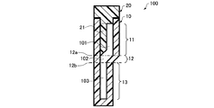
FIG. 1 is a diagram conceptually showing a
1.1.器体
器体10は、長手方向を有する。器体10は、長手方向に沿って延びた形状を有し、一端が開放され、他端が閉鎖されたチューブ状の形状を有する。すなわち、器体10は、開放された一端側を重力の作用する方向とは反対側に位置するように配置したときに、内部に液体を湛えることができる形状を有する。器体10は、長手方向において、3つの温度制御される領域を形成できる程度の長さを有する。
1.1. The
器体10は、長手方向において、開放された一端側から順に、第1領域11、第2領域12および第3領域13を有する。
The
第1領域11は、器体10の内部に液体が導入され、蓋体20によって封止された場合に、液体が器体10の長手方向に流通することのできる第1空間101が形成される領域である。また、第1領域11は、蓋体20によって器体10が封止された場合に、長手方向に直交する断面において蓋体20の突起21を含む領域である。第1領域11は、器体10の一端側の端部の開口に接続していてもよいし接続していなくてもよい。すなわち、第1領域11は、器体10の一端側の開口の位置から器体10の他端側へ延びていてもよいし、器体10の開口から所与の間隔を隔てた位置から他端側へ延びていてもよい。器体10において、他端側へ延びる第1領域11の起点となる位置は、蓋体20の突起21の根本に位置する。また、器体10の第1領域11において、長手方向に直交する断面における器体10の内壁によって囲まれる領域の面積は一定であってもよい。このようにすれば、容器100内に液滴D、液滴Dと相分離し、液滴Dよりも比重の小さい液体Lとを導入した場合に、重力の作用によって液滴Dを容器100内部の空間を移動させることを容易化することができる。
The
第1領域11の長手方向の長さは、蓋体20の突起21の長手方向における長さと一致するが、該長さは特に限定されず、例えば、1mm以上10cm以下、5mm以上5cm以下とすることができる。また、例えば、10mm以上3cm以下、15mm以上2cm以下とすれば、容器100の内部に形成される第1空間101を温度制御する際の他の領域の温度との干渉を抑制したり、他の領域との温度変化の急峻性を向上したりすることが
できる。
The length in the longitudinal direction of the
第1空間101には、例えば液体を導入することができる。第1空間101の形状は、特に制限されないが、例えば、第1空間101の長手方向に直交する断面における輪郭は、円形、楕円形、多角形、円環形、多角環形等とすることができる。なお、第1空間101の長手方向に直交する断面における外形を円環形とする場合は、例えば、第1領域11の内壁面を、長手方向に直交する断面において円形とし、蓋体20の突起21の長手方向に直交する断面を円形とし、さらに、突起21を第1領域11の内壁面に接触させないように配置するような蓋体20の形状とすることによって実現することができる。
For example, a liquid can be introduced into the
また、第1空間101の長手方向に直交する断面における面積は、特に限定されない。しかし、係る面積は、例えば、容器100に液滴Dと、該液滴Dと相分離する液体を導入した場合に、第1空間101の長手方向に、液滴Dが移動できる程度の大きさとすることが好ましい。
Moreover, the area in the cross section orthogonal to the longitudinal direction of the
第1空間101は、蓋体20によって器体10が封止された場合に、器体10の第2領域12の内部の第2空間102と連通することができる。
The
第2領域12は、器体10の内部に液体が導入された場合に、液体が器体10の長手方向に流通することのできる第2空間102を形成する領域である。第2領域12は、拡径部12a及び縮径部12bを有する。
The
第2領域12の拡径部12aは、第1領域11の他端側(器体10における開放端と反対側)に接続する部分である。拡径部12aは、第2領域12において、他の部分よりも内径の拡張した部分である。第2領域12において、拡径部12aから縮径部12bへ向かって、内径(長手方向に直交する断面における第2空間102の面積)が縮小する。
The
なお、ここでは単に内径と表現しているが、第2領域12の内径とは、第2空間102の長手方向に直交する断面における輪郭が、円形以外の場合には、同面積の円形とした場合の直径のことを指すものとする。
Here, the inner diameter of the
第2空間102には、例えば液体を導入することができる。第2空間102の長手方向に直交する断面の輪郭の形状は、特に制限されないが、例えば、円形、楕円形、多角形等とすることができる。また、第2空間102の長手方向に直交する断面の輪郭の形状は、拡径部12a及び縮径部12bにおいて、第1空間101及び第3空間103と滑らかに接続していることが好ましい。このようにすれば、容器100に液滴Dと、該液滴Dと相分離する液体を導入した場合に、長手方向に液滴Dが移動しやすくなる。
For example, a liquid can be introduced into the
第2空間102の長手方向に直交する断面における面積は、特に限定されない。しかし、係る面積は、例えば、容器100に液滴Dと、該液滴Dと相分離する液体を導入した場合に、第1空間101から第3空間へ液滴Dが移動できる程度の大きさとすることが好ましい。
The area in the cross section orthogonal to the longitudinal direction of the
拡径部12aは、内部に形成される第2空間102の、長手方向に直交する断面が他の部分に比較して拡大している領域を形成する部分であり、縮径部12bは、内部に形成される第2空間102の、長手方向に直交する断面が他の部分に比較して縮小している領域を形成する部分である。そして、拡径部12aにおいて、第2空間102は、第1空間101と連通し、縮径部12bにおいて第2空間102は、第3空間103と連通する。
The
第2領域12の器体10における長手方向の長さは、特に限定されず、例えば、1mm
以上3cm以下、2mm以上2cm以下とすることができる。また、例えば、3mm以上2cm以下、5mm以上1cm以下とすれば、第2空間102を温度制御する際の他の領域の温度との干渉を抑制したり、他の領域との温度変化の急峻性を向上したりすることができる。また、器体10の第2領域12の肉厚は、特に限定されず、拡径部12a及び縮径部12bにおいて異なっていてもよい。図示の例では、拡径部12a及び縮径部12bにおいてほぼ同じ肉厚となっている。
The length in the longitudinal direction of the
It can be 3 cm or less and 2 mm or more and 2 cm or less. Further, for example, when the thickness is 3 mm or more and 2 cm or less and 5 mm or more and 1 cm or less, interference with the temperature of another region when the temperature of the
また、器体10の第2領域の長手方向における長さは、第1領域11及び第3領域13の長手方向における長さよりも短くてもよい。このようにすれば、第1領域11、第2領域12及び第3領域13のそれぞれにおいて温度制御する場合、制御される領域を離間させやすいので、例えば、温度制御用のヒーター等の配置の自由度を高めることができる。
In addition, the length of the second region of the
拡径部12aから縮径部12bへ向かって内径が縮小する態様については、特に限定されない。例えば、拡径部12aから縮径部12bへ向かって内径が単調に減少してもよいし、極大や極小を有して減少してもよい。すなわち、器体10の第2領域12の内壁は、テーパー形状であってもよい。このようにすれば、器体10の第2領域12の形状がより単純化され、例えば、バルーン成型、射出成形等の各種の成型方法を容易に適用することができ、製造をさらに容易化することができる。
The aspect in which the inner diameter decreases from the
また、換言すると、器体10の長手方向において一端から他端に向かう方向を正とし、器体10の一端側の端を原点とした長手方向の位置を位置xとし、長手方向に直交する切断面における器体10の内壁の輪郭が占める面積を関数f(x)とした場合に、関数f(x)の位置xによる微分f’(x)の絶対値|f’(x)|が最大となる位置xが第2領域12に存在する。
In other words, in the longitudinal direction of the
第2領域12が拡径部12a及び縮径部12bを有するので、結果として、第2領域12の内部の第2空間102には、容器100の長手方向に対して傾斜した側面が形成される。係る側面が存在することにより、容器100の長手方向を重力の作用する方向に対して適切な角度で傾斜させれば、容器100の内部に液滴Dと、該液滴Dと相分離し、かつ、液滴Dよりも比重の小さい液体を導入した場合に、液滴Dが容器100内で第1領域11側から第3領域13側へ落下(滑落、転落)しないように第2領域12付近に停留させることができる。
Since the
ここで、容器100の長手方向に対する当該側面の傾斜角度θと、容器100の長手方向の重力の作用する方向に対する傾斜角度αとを、図2及び図3に示すように定義する。なお、容器100の長手方向は、図中の符号LDで示された鎖線である。
Here, the inclination angle θ of the side surface with respect to the longitudinal direction of the
図2に示すように、第2領域12は、第3領域13から第1領域11側に向かって内径が拡径しており、第2領域12において、第2空間102の傾斜した内壁12cが形成される。図2に示すように、内壁12cの傾斜角度θは、容器100の長手方向を含む平面で切断した場合に、容器100の長手方向を基準にして内壁12cの接線が傾斜した角度とする。傾斜角度θは、0°を超え、90°以下の値を採る。また、図2(a)では、内壁12cは断面において直線状に描いてあるが、図2(b)に示すように曲線であってもよく、この場合には、内壁12cの傾斜角度θは、容器100の長手方向に対して最も傾斜した内壁12cの部分の接線に対応する角度とする。
As shown in FIG. 2, the inner diameter of the
一方、図3(a)に示すように、容器100の長手方向の重力の作用する方向に対する傾斜角度αは、重力の作用する方向Gに対して、器体10の長手方向が平行でかつ第1領域11、第2領域12及び第3領域13の順に並ぶ向きが同じ向きに配置された場合を0°(360°)と定義する。また傾斜角度αは、図3(b)に示すように、重力の作用す
る方向Gに対して、器体10の長手方向が平行、かつ第1領域11、第2領域12及び第3領域13の順に並ぶ向きが反対向きに配置された場合を180°と定義する。このようにして、図4(a)に示すように、容器100の長手方向の重力の作用する方向に対する傾斜角度αを定義する。
On the other hand, as shown in FIG. 3 (a), the inclination angle α of the
図4(a)、(b)を参照して、重力の作用によって液滴Dが第1領域11側から第3領域13側へ落下しないように第2領域12付近に留める条件としては、傾斜角度θ及び傾斜角度αを用いると、90°≦(θ+α)となる。この関係を満たすように、容器100の長手方向に対する当該側面の傾斜角度θと、容器100の傾斜角度αとを選べば、容器100の内部に液滴Dと、該液滴Dと相分離し、かつ、液滴Dよりも比重の小さい液体を導入した場合に、液滴Dを容器100内で第1領域11側から第3領域13側へ落下しないように第2領域12付近に留めることができる。また、液体Lの粘度や、液滴Dの落下速度等を考慮して傾斜角度θ及び傾斜角度αは適宜選択されることができる。
Referring to FIGS. 4A and 4B, the condition for keeping the droplet D near the
第3領域13は、器体10の内部に液体が導入された場合に、液体が器体10の長手方向に流通することのできる第3空間103を形成する領域である。第3領域13は、第2領域12の縮径部12bと接続している。第3空間103は、器体10の第2領域12の内部の第2空間102と連通することができる。
The
第3領域13の器体10における長手方向の長さは、特に限定されず、例えば、1mm以上10cm以下、5mm以上5cm以下とすることができる。また、例えば、10mm以上3cm以下、15mm以上2cm以下とすれば、容器100の内部に形成される第3空間103を温度制御する際の他の領域の温度との干渉を抑制したり、他の領域との温度変化の急峻性を向上したりすることができる。
The length in the longitudinal direction of the
第3空間103の形状は、特に制限されないが、例えば、長手方向に直交する断面における輪郭は、円形、楕円形、多角形等とすることができる。また、第3空間103の長手方向に直交する断面における面積は、特に限定されない。しかし、係る面積は、例えば、容器100に液滴Dと、該液滴Dと相分離する液体Lを導入した場合に、第3空間103の長手方向に、液滴Dが移動できる程度の大きさとすることが好ましい。また、器体10の第3領域13において、長手方向に直交する断面における器体10の内壁によって囲まれる領域の面積は一定であってもよい。
The shape of the
また、器体10の第3領域13の内壁は、長手方向からの平面視において、器体10の第1領域11の内壁よりも内側に位置するようにしてもよい。このようにすれば、器体10の構造が単純となるため、例えば、バルーン成型、射出成形等の各種の成型方法を適用することができ製造を容易化することができる。
Further, the inner wall of the
器体10の材質としては、例えば、ポリプロピレン、ポリカーボネート、ポリアクリル酸、ポリメタクリル酸、ポリエチレンなどの高分子材料、ガラス、金属などの無機材料を例示することができる。器体10の耐熱性、熱伝導率、透明性の観点から、器体10の材質としては、ポリプロピレン、ポリカーボネートがより好ましい。また、器体10は表面処理等が施されてもよく、これにより例えば、液滴Dと、該液滴Dと相分離する液体Lを導入した場合に液滴Dの器体10内での移動を容易にすることができる。
Examples of the material of the
1.2.蓋体
蓋体20は、器体10の一端の開口を封止することができる。蓋体20が器体10の一端を封止する態様は特に限定されず、蓋体20が器体10の内部に嵌合する栓のようになっていてもよいし、蓋体20が器体10の外側に嵌合するキャップのようになっていてもよいし、その両者を組み合わせた態様であってもよい。さらに、蓋体20と器体10とを
固定するような、スクリュー構造又はOリング等のガスケットを有して両者が固定され封止されてもよい。図1の例では蓋体20が器体10の内部に嵌合する栓のようになっている。
1.2. Lid The
蓋体20は、器体10の内部に突出して配置される突起21を含む。突起21は、蓋体20による器体10の封止にあずかる部分を除いた部分であり、器体10を封止する際に、器体10の内部に挿入され配置される部分である。そして、器体10を封止した場合に、器体10の内部に突起21が位置している領域が上述した第1領域11である。
The
容器100の長手方向における突起21の長さは、器体10において第2領域12を形成できる範囲であれば、特に限定されない。器体10を蓋体20によって封止した際に、長手方向に直交する方向における突起21の配置される位置についても、特に限定されない。例えば、図1の例では、器体10を蓋体20によって封止した際、突起21は、器体10の内側側面に接しているが、突起21は、器体10の内側側面に接していなくてもよい。
The length of the
突起21の形状は、特に制限されない。突起21の形状は、例えば、封止された際の第1空間101の容器100の長手方向に直交する断面の面積が一定となるように形成されることができる。また、器体10の第1領域11の内部の空間の長手方向に直交する断面の形状や面積が変化している場合には、これに対応するように突起21の長手方向に直交する断面の面積や形状を変化させてもよい。また突起21の長手方向に直交する断面の形状は、容器100内に液滴Dと、該液滴Dと相分離する液体Lを導入し、蓋体20によって器体10が封止された場合に、第1空間101内で液滴Dが移動できる範囲で、特に限定されず、曲線及び直線を任意に組み合わせた形状とすることができる。突起21の具体的な形状の例としては、円柱状、角柱状、板状等が挙げられる。
The shape of the
突起21の機能の1つとしては、器体10を封止する前において、器体10の第1領域11の内壁面によって形成される空間を、器体10を封止することによって第1空間101とすることが挙げられる。これにより、器体10の内部の空間の体積を小さくすることができる。そのため、容器100内の第1空間101に液体等が導入され温度勾配が形成された場合に、該液体の対流を抑制することができ、温度勾配の対流による乱れ等を抑制することができる。
As one of the functions of the
蓋体20の材質としては、例えば、ポリプロピレン、ポリカーボネート、ポリアクリル酸、ポリメタクリル酸、ポリエチレンなどの高分子材料、ガラス、金属などの無機材料を例示することができる。蓋体20の耐熱性、熱伝導率の観点から、蓋体20の材質としては、ポリプロピレン、ポリカーボネートがより好ましい。また、蓋体20は表面処理等が施されてもよく、これにより例えば、液滴Dと、該液滴Dと相分離する液体Lを導入した場合に液滴Dの容器100内での移動を容易にすることができる。
Examples of the material of the
1.3.容器の傾斜
図5は、容器100内に液滴Dと、該液滴Dと相分離し該液滴Dよりも比重の小さい液体Lを導入した場合の、液滴Dの容器100内での移動の様子を模式的に示す図である。
1.3. Inclination of the container FIG. 5 shows the droplet D in the
液滴Dの体積は、滴の形状を液体L内で維持できる範囲で任意である。液滴Dは、液体Lよりも比重が大きいため、図5(a)に示すように、容器100の傾斜角度αが0°である場合には、容器100の第3領域13(第3空間103)の端まで落下する。また、図5(b)に示すように、容器100の傾斜角度αが180°である場合には、容器100の第1領域11(第1空間101)の端まで落下する。
The volume of the droplet D is arbitrary as long as the shape of the droplet can be maintained in the liquid L. Since the specific gravity of the droplet D is larger than that of the liquid L, as shown in FIG. 5A, when the inclination angle α of the
次に、図5(b)の状態から、図5(c)に示すように、容器100を(90°−θ)≦αの関係を満たす傾斜角度αまで傾斜させると、液滴Dは、第1領域11から第3領域13へ向かって落下(滑落、転落)するが、第2領域12の形状の作用により、第2領域12付近において停留することができる。なお、容器100の例では、液滴Dを第1領域11から第3領域13の方向へ移動させる場合には、液滴Dが器体10の内壁に沿うように回転方向を選択して移動させる。
Next, when the
1.4.作用効果
本実施形態の容器100は、長手方向に沿って内部の空間が第1領域11、第2領域12、及び第3領域13の順に連通している。すなわち、器体10を蓋体20によって封止した場合に、第1空間101、第2空間102及び第3空間103が連通している。そのため、容器100内に温度制御を施す液滴D、及び液滴Dと相分離し、液滴Dよりも比重の小さい液体Lとを導入して封止した場合に、重力の作用によって液滴Dを容器100内の空間内を移動(落下)させることができる。そして、容器100は、拡径部12a及び縮径部12bを有する第2領域12を有するため、重力の作用によって第1領域11から第3領域13へと液滴Dを移動させる際に、容器100の傾斜角度αを調節することによって、第2領域12において液滴Dを停止させることができる。さらに、第1領域11においては、蓋体20の突起21が存在するため、容器100内の空間の体積が小さくなるので、第1空間101における液体Lの対流を抑制することができる。これにより、液滴Dを正確に温度制御された各領域間で簡易な操作によって移動させることができる。そのため、例えば、液滴DをPCRの反応液とし、第1領域11、第2領域12及び第3領域13を適宜な温度に設定した場合に、反応液に対して3段階の熱サイクルを容易に施すことができる。
1.4. Operational Effect In the
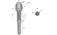
2.具体例
図6は、本発明に係る容器の一実施形態である容器110を示す模式図である。図6(b)は、図6(a)のI−I線における断面に相当する。図7は、容器110において器体10を蓋体20にて封止する様子を模式的に示す図である。図8は、容器110の傾斜の様子を模式的に示す図である。本実施形態に係る容器110は、器体10と、蓋体20と、を含むが、上述の容器100において説明したと同様の部材等には、同様の符号を付して詳細な説明を省略する。
2. Specific Example FIG. 6 is a schematic view showing a
容器110における器体10は、第1領域11、第2領域12及び第3領域13を有する点で、上述した器体10と同様である。容器110における器体10は、図6に示すように、蓋体20によって封止される際に、空洞14が形成されるようになっている点、及び蓋体20の突起21が器体10の内壁面に接することなく配置される点において、上述した器体10と相違している。
The
容器110における蓋体20は、突起21を有する点で上述した容器100における蓋体20と同様である。しかし、容器110における蓋体20は、器体10を封止する際に、空洞14を形成できる形状となっている。空洞14は、器体10に液滴D及び液体Lを導入し、蓋体20によって封止する際に、主に突起21による液体Lの排除体積を収容できる程度の大きさを有している。そして、図7に示すように、導入される液体Lの体積を適宜に設定する(図7(a))ことにより、封止の際に、第1空間101、第2空間102及び第3空間103に気泡を生じさせず、かつ、液体Lを容器110から溢れさせないように封止することができる(図7(b))。このように容器110では、器体10に、蓋体20によって封止される際に、空洞14が形成されるようになっているため、第1空間101等に気泡を生じにくく、かつ液体Lが溢れにくいという効果を得ることができる。また、空洞14が存在するため、液体Lを収容する際に多少の量の誤差を含んでもよく液体Lの量の自由度が高まっている。
The
また、容器110においては、器体10の第2領域12の内部の第2空間102の側面は、テーパー状となっており、その接線が容器110の長手方向となす角は、容器110の長手方向に沿って変化している。このようにしても、液滴Dが落下することを留める効果を得ることができる。すなわち、図8(b)に示すように、容器110内に液滴Dと、該液滴Dと相分離し、かつ該液滴Dよりも比重の小さい液体Lを導入した場合、液滴Dを容器110内で移動させることができ、傾斜角度を適宜に選べば、第2領域12付近に液滴Dを停留させることができる。
Further, in the
液滴Dは、液体Lよりも比重が大きいため、図8(a)に示すように、容器110の傾斜角度αが180°である場合には、容器110の第1領域11(第1空間101)の端まで落下する。また、図8(c)に示すように、容器110の傾斜角度αが0°である場合には、容器110の第3領域13(第3空間103)の端まで落下する。
Since the specific gravity of the droplet D is larger than that of the liquid L, as shown in FIG. 8A, when the inclination angle α of the
また、図8(a)に示すように、容器110の傾斜角度αが180°である状態から、図8(b)に示すように、容器110を(90°−θ)≦αの関係を満たす傾斜角度αまで傾斜させると、液滴Dは、第1領域11から第3領域13へ向かって落下(滑落、転落)するが、第2領域12の形状による段差を超えることができず、第2領域12付近において停留する。なお、容器110の例では、突起21が長手方向に直交する断面において中心に配置されているため、液滴Dを第1領域11から第3領域13の方向へ移動させる場合には、液滴Dが器体10の内壁に沿うように移動させることができる。
Further, as shown in FIG. 8A, from the state where the inclination angle α of the
3.熱サイクル装置
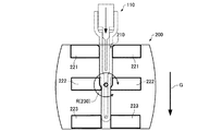
本実施形態の熱サイクル装置200は、上述の容器110を装着する装着部210と、第1温度制御部221と、第2温度制御部222と、第3温度制御部223と、回転機構230とを含む。そして、容器110を装着した場合に、第1温度制御部221は器体10の第1領域11の温度を制御し、第2温度制御部222は第2領域12の温度を制御し、第3温度制御部223は第3領域13の温度を制御し、回転機構230は、装着部210および各前記温度制御部を、重力の作用する方向に対して直交する成分を有する回転軸の周りに回転させる。
3. Thermal Cycle Device The
図9は、本実施形態に係る熱サイクル装置200の要部を模式的に示す図である。図10及び図11は、熱サイクル装置200の回転の様子を示す図である。
FIG. 9 is a diagram schematically showing a main part of the
本実施形態の熱サイクル装置200は、容器110を装着する装着部210を有する。装着部210は、容器110を装着した場合に、容器110の第1領域11、第2領域12及び第3領域13が、それぞれ第1温度制御部221、第2温度制御部222及び第3温度制御部223に熱的に接触して温度制御されるように形成されている。
The
本実施形態に係る熱サイクル装置200は、容器110の第1空間101、第2空間102、及び第3空間103に沿って(液滴Dが移動する方向に沿って)温度勾配を形成することができる。なお、第1温度制御部221、第2温度制御部222及び第3温度制御部223は、それぞれ、第1領域11、第2領域12及び第3領域13の一部又は全部に対して温度制御してもよい。
The
装着部210は、容器110を装着する構造である。図9に示される例では、第1温度制御部221、第2温度制御部222及び第3温度制御部のそれぞれの一部が装着部210を構成している。また、図示しないが、装着部210は、他の構成、例えば容器110を装着する際のガイドやスペーサーとなる部材や、容器110を固定するための部材を含んで構成されてもよい。図9の例では、装着部210は、容器100を差し込んで装着す
るスロット構造となっている。
The mounting
熱サイクル装置200に設けられる装着部210の個数は、特に限定されない。装着部210の数が複数である場合は、複数の容器110をそれぞれ装着することができる。なお、装着部210は容器110を保持できる構造であればよい。例えば、容器110の形状に合わせた窪みに容器110をはめ込む構造や、容器110を挟んで保持する構造を採用してもよい。
The number of mounting
本実施形態の熱サイクル装置200は、装着部210が設けられた第1温度制御部221、第2温度制御部222及び第3温度制御部223を含む。
The
各温度制御部は、装着部210に容器110を装着した場合に、液滴Dが移動する移動方向に温度勾配を形成する構成である。ここで、「温度勾配を形成する」とは、所定の方向に沿って温度が変化する状態を形成することを意味する。したがって、「液滴Dが移動する移動方向に温度勾配を形成する」とは、液滴Dが移動する移動方向に沿って温度が変化する状態を形成することを意味する。「所定の方向に沿って温度が変化する状態」は、例えば、所定の方向に沿って温度が単調に高く又は低くなっていてもよいし、所定の方向に沿って、温度が高くなる変化から低くなる変化へ、又は、低くなる変化から高くなる変化へ、途中で変化していてもよい。図9に示される例では、第1温度制御部221、第2温度制御部222、及び第3温度制御部223の3つの温度制御部によって温度勾配が形成されているが、所望の温度勾配が形成される限り、温度制御部の個数は、1つ若しくは2つでも、又は、4つ以上であってもよい。
Each temperature control unit is configured to form a temperature gradient in the moving direction in which the droplet D moves when the
第1温度制御部221、第2温度制御部222及び第3温度制御部223は、それぞれ、例えば、熱源、アルミニウムのヒートブロック等の熱伝導体を含んで構成されてもよい。熱源としては、ヒーター(電熱線)、カートリッジヒーター、カーボンヒーター、シートヒーター、IHヒーター(電磁誘導加熱器)、加熱液体、加熱気体などを使用してもよい。また、各温度制御部は、必要に応じて、導線や配管を備えてもよく、外部電源等に接続してもよい。これらのうちでもカートリッジヒーターは温度制御が容易であるので、カートリッジヒーターを採用することで、制御の温度を安定させることを容易化することができる。
The first
第1温度制御部221、第2温度制御部222及び第3温度制御部223は、装着部210に容器110を装着した場合に、それぞれ容器110の器体10の第1領域11、第2領域12及び第3領域13をそれぞれ第1温度、第2温度及び第3温度となるように制御する。
The first
第1温度制御部221、第2温度制御部222及び第3温度制御部223は、互いに異なる温度に制御されることができる。この場合、各温度制御部は、互いに熱的な接触が小さい態様で配置されることが好ましい。例えば、各温度制御部は互いに離れた位置(物理的に接触しない位置)に設けることが好ましい。また、各温度制御部は、熱サイクル装置200に、断熱性の部材等により熱的な干渉が小さくされた状態で設置されてもよい。
The first
各温度制御部は、装着部210に容器110を装着した場合に、容器110に対して熱的に接触する。熱的に接触する態様としては、各温度制御部と容器110とが直接に接触している態様や、容器110との間に他の熱伝導性の部材を介して接触している態様などが挙げられる。また、熱を適切に伝えることができれば、各温度制御部と容器110との間に空間があっても良い。
Each temperature control unit is in thermal contact with the
第1温度制御部221、第2温度制御部222及び第3温度制御部223の温度は、図
示しない温度センサー及び制御部によって制御されてもよい。温度センサーとしては例えば熱電対を用いることができ、これに限らず、例えば測温抵抗体やサーミスタを使用してもよい。また、制御部は、回転機構を制御してもよい。
The temperatures of the first
回転機構230は、装着部210、並びに、第1温度制御部221、第2温度制御部222及び第3温度制御部223を、重力の作用する方向に対して直交する成分を有し、かつ、装着部210に容器100を装着した場合に、液滴Dが移動する方向に対して直交する成分を有する回転軸Rの周りに回転させる機構である。図9ないし図11では、回転軸Rのみを表示し、回転機構230は省略されている。
The
「重力の作用する方向に対して直交する成分を有する」方向は、「重力の作用する方向に対して平行な成分」と「重力の作用する方向に対して直交する成分」とのベクトル和で表した場合における、重力の作用する方向に対して直交する成分を有する方向である。また、「液滴Dの移動方向に対して直交する成分を有する」方向は、「液滴Dの移動方向に対して平行な成分」と「液滴Dの移動方向に対して直交する成分」とのベクトル和で表した場合における、液滴Dの移動方向に対して直交する成分を有する方向である。 The direction “having a component orthogonal to the direction in which gravity acts” is the vector sum of “component parallel to the direction in which gravity acts” and “component perpendicular to the direction in which gravity acts”. It is a direction having a component orthogonal to the direction in which gravity acts in the case where it is expressed. In addition, the direction “having a component orthogonal to the moving direction of the droplet D” includes “a component parallel to the moving direction of the droplet D” and “a component orthogonal to the moving direction of the droplet D”. Is a direction having a component orthogonal to the moving direction of the droplet D.
したがって、装着部210に容器110を装着した状態で、回転軸R周りに装着部210及び第1温度制御部221、第2温度制御部222及び第3温度制御部223を回転させると、容器110内の液滴Dが、容器110の第1空間101、第2空間102及び第3空間103の内部を移動することができる。図9ないし図11の例では、回転軸Rは、重力の作用する方向に対して垂直となっている例を示している。
Therefore, when the mounting
なお、容器110の長手方向が、重力の作用する方向Gに対して垂直となる配置以外の配置(図に示す配置)であれば液滴Dは移動することができることは容易に理解されよう。そのため、回転機構230は、必ずしも回転軸Rの周りに180°以上回転させることができる態様である必要はなく、また、回転機構230は、回転軸Rの周りに360°以上回転させることができる態様であってもよい。
It will be easily understood that the droplet D can move if the longitudinal direction of the
回転機構230は、装着部210及び第1温度制御部221、第2温度制御部222及び第3温度制御部223を同一の回転軸Rの周りに回転させてもよい。言い換えると、装着部210を回転させる回転軸Rと第1温度制御部221、第2温度制御部222及び第3温度制御部223を回転させる回転軸Rとは共通(同じ)であってもよい。
The
また、回転機構230は、図示しないモーター及び駆動軸を含んでもよく、当該駆動軸と必要に応じて歯車やフランジ等とを接続して構成されてもよい。回転機構230がモーターを有する場合には、例えばモーターの駆動軸を回転軸Rとして、モーターの動作により、回転軸Rの周りに回転されることができる。回転軸Rと装着部210との位置関係については、特に制限はないが、装置の小型化や、装置内の他の部材との干渉を考慮して適宜設定されることができる。なお、回転機構230としては、モーターに限らず、例えばハンドル、ぜんまい等を採用してもよい。
The
熱サイクル装置200は、図示しない制御部を含んでいてもよい。制御部は、回転機構230及び第1温度制御部221、第2温度制御部222及び第3温度制御部223のうち、少なくとも1つを制御することができる。制御部は、専用回路により実現して制御を行うように構成されていてもよい。また、制御部は、例えばCPU(Central Processing
Unit)がROM(Read Only Memory)やRAM(Ran dom Access Memory)等の記憶装置に記憶された制御プログラムを実行することによりコンピューターとして機能し、制御を行うように構成されていてもよい。この場合、記憶装置は、制御に伴う中間データや制御結果などを一時的に記憶するワークエリアを有していてもよい。
The
The Unit may function as a computer by executing a control program stored in a storage device such as a ROM (Read Only Memory) or a RAM (Random Access Memory), and may be configured to perform control. In this case, the storage device may have a work area for temporarily storing intermediate data and control results associated with the control.
本実施形態の熱サイクル装置200は、容器110を装着した場合に、第1温度制御部221が器体10の第1領域11の温度を制御し、第2温度制御部222が第2領域12の温度を制御し、第3温度制御部223が第3領域13の温度を制御することができる。また本実施形態の熱サイクル装置200は、これに加えて、回転機構230が、装着部210および各前記温度制御部を、重力の作用する方向に対して直交する成分を有する回転軸の周りに回転させることができる。これにより本実施形態の熱サイクル装置200は、容器110に液滴Dと、該液滴Dと相分離し、該液滴Dよりも比重の小さい液体Lを導入した場合、液滴Dを容器110内で移動させて熱サイクルを施すことができる。そして、回転機構230により、容器110の傾斜角度αを自在に変更することができるため、容器110を(90°−θ)≦αの関係を満たす傾斜角度αまで傾斜させることもでき、傾斜角度αで回転を停止させることもできる(例えば図11に示す状態)。そのため、液滴Dに対して3段階の温度の熱サイクルを容易に施すことができる。
In the
4.容器の使用方法
以下に、本発明に係る容器の使用方法として、PCRの反応液を上述の容器110内で、上述の熱サイクル装置200を用いて移動させて熱サイクルを施す態様を一例として説明する。
4). Method for Using Container Hereinafter, as an example of a method for using a container according to the present invention, an embodiment in which a PCR reaction solution is moved in the above-described
まず、図7(a)に示すように、蓋体20を外した状態で、容器110の器体10に、PCRの反応液(液滴D)及びオイル(液体L)を収容する。反応液は、オイル中で、滴として存在する程度の体積とし、係る滴が容器110に形成される第1空間101、第2空間102及び第3空間103を移動できる程度の大きさとする。
First, as shown in FIG. 7A, the PCR reaction liquid (droplet D) and oil (liquid L) are stored in the
PCRの反応液としては、例えば、標的核酸を含み、酵素、dNTP、プローブ、プライマー及びバッファーの少なくとも一種を含む、滅菌水、蒸留水、イオン交換水等の水溶液が挙げられる。ここで、dNTPは、4種類のデオキシリボヌクレオチド三リン酸(deoxynucleotide triphosphate)(dATP(Deoxyadenosine triphosphate)、dCTP(Deoxycytidine triphosphate)、dGTP(Deoxyguanosine triphosphate)、及びdTTP(Thymidine triphosphate)を混合したもの)を表す。 Examples of the reaction solution for PCR include aqueous solutions such as sterilized water, distilled water, and ion-exchanged water that contain a target nucleic acid and contain at least one of an enzyme, dNTP, probe, primer, and buffer. Here, dNTP represents four types of deoxynucleotide triphosphate (a mixture of dATP (Deoxyadenosine triphosphate), dCTP (Deoxycytidine triphosphate), dGTP (Deoxyguanosine triphosphate), and dTTP (Thymidine triphosphate)). .
標的核酸は、例えば、DNAやRNA(DNA:Deoxyribonucleic Acid、及び/又はRNA:Ribonucleic Asid)である。標的核酸は、PCRの鋳型として利用される。標的核酸を含む検体としては、血液、鼻腔粘液、口腔粘膜、その他各種の生体試料などが挙げられ、標的核酸はこれらの検体から抽出等により精製されたものであってもよい。 The target nucleic acid is, for example, DNA or RNA (DNA: Deoxyribonucleic Acid and / or RNA: Ribonucleic Asid). The target nucleic acid is used as a PCR template. Examples of the sample containing the target nucleic acid include blood, nasal mucus, oral mucosa, and other various biological samples. The target nucleic acid may be purified from these samples by extraction or the like.
またオイルとしては、例えば、ジメチルシリコーンオイル等のシリコーン系オイル、パラフィン系オイル及びミネラルオイル並びにそれらの混合物から選択される一種を挙げることができる。 Examples of the oil include one selected from silicone oil such as dimethyl silicone oil, paraffin oil and mineral oil, and mixtures thereof.
器体10にPCRの反応液及びオイルを収容した後、図7(b)に示すように、蓋体20によって器体10を封止する。そして、図10に示すように、熱サイクル装置200の装着部210に容器110を装着する。
After the PCR reaction solution and oil are stored in the
本例では、PCRにおける熱変性温度を95℃、アニール温度を55℃、伸長温度を55℃とする例を説明する。しかし、このような温度範囲に限らず、本実施形態の熱サイクル装置200では、例えば、熱変性温度を70℃以上、85℃以上、あるいは90℃以上、アニール/伸長温度を55℃以上70℃以下、55℃以上68℃以下、あるいは60℃以上65℃以下、などと設定することが容易であり、将来の酵素等の開発によって必要とされる温度範囲も含め、各種のPCRに必要な温度に応じて各温度制御部の温度を設定す
ることができる。また、例えば、ワンステップRT−PCR等に適用することもでき、条件に応じたPCRを行うことができる。
In this example, an example will be described in which the thermal denaturation temperature in PCR is 95 ° C., the annealing temperature is 55 ° C., and the extension temperature is 55 ° C. However, the
ここでは、第1温度制御部221を55℃に制御して第1空間101において反応液に対してアニール反応を行い、第2温度制御部222を72℃に制御して第2空間102において反応液に対して伸長反応を行い、第3温度制御部223を95℃に制御して第3空間103において反応液に対して熱変性反応を行うものとする。
Here, the first
そして、回転機構230を動作させることによって図10(b)の状態(α=180°)として反応液を移動させる。この状態では、反応液(液滴D)は、第1領域11(第1空間101)にあって、55℃でアニール反応が行われる。次に回転機構230を動作させて、図11に示すように、(90°−θ)≦αの関係を満たす傾斜角度αまで回転して停止する。このとき、反応液は、図11、図8(b)に示すように、重力により容器100の中を移動して第2領域12付近に停留する。ここでは72℃で伸長反応が行われる。さらに回転機構230を動作させて(α=0°)反応液を移動させると(図10(a)の状態)、反応液は第3領域13(第3空間103)に移動する。この状態で熱変性反応が行われる。そして、回転機構230を動作させると(α=180°)最初の状態(図10(b))に戻り、反応液は、第1領域11(第1空間101)に移動されて、引き続き次のアニール反応を行うことができる。これにより、PCRの反応液に対して熱サイクルを施すことができる。
Then, by operating the
なお、回転機構230による回転の方向は、反応液を第2領域12に停留させることができる範囲で任意である。また、第1温度制御部221を95℃に制御して第1空間101において反応液に対して熱変成反応を行い、第2温度制御部222を55℃に制御して第2空間102において反応液に対してアニール反応を行い、第3温度制御部223を72℃に制御して第3空間103において反応液に対して伸長反応を行うようにしてもよく、PCRの反応液に対して施すべき熱サイクルを考慮してこれらの条件を適宜変更して行ってもよい。
The direction of rotation by the
本発明は、上述した実施形態に限定されるものではなく、さらに種々の変形が可能である。例えば、本発明は、実施形態で説明した構成と実質的に同一の構成(例えば、機能、方法及び結果が同一の構成、あるいは目的及び効果が同一の構成)を含む。また、本発明は、実施形態で説明した構成の本質的でない部分を置き換えた構成を含む。また、本発明は、実施形態で説明した構成と同一の作用効果を奏する構成又は同一の目的を達成することができる構成を含む。また、本発明は、実施形態で説明した構成に公知技術を付加した構成を含む。 The present invention is not limited to the above-described embodiments, and various modifications can be made. For example, the present invention includes substantially the same configuration (for example, a configuration having the same function, method and result, or a configuration having the same purpose and effect) as the configuration described in the embodiment. In addition, the invention includes a configuration in which a non-essential part of the configuration described in the embodiment is replaced. In addition, the present invention includes a configuration that exhibits the same operational effects as the configuration described in the embodiment or a configuration that can achieve the same object. In addition, the invention includes a configuration in which a known technique is added to the configuration described in the embodiment.
10…器体、11…第1領域、12…第2領域、12a…拡径部、12b…縮径部、12c…内壁、13…第3領域、14…空洞、20…蓋体、21…突起、100,110…容器、101…第1空間、102…第2空間、103…第3空間、200…熱サイクル装置、210…装着部、221…第1温度制御部、222…第2温度制御部、223…第3温度制御部、230…回転機構、D…液滴、L…液体、R…回転軸
DESCRIPTION OF
Claims (6)
前記器体の内部に突出して配置される突起を含み、前記器体の前記一端を封止する蓋体と、
を含む熱サイクル装置用の容器であって、
前記器体は、
前記蓋体によって前記器体を封止した場合に、前記長手方向に直交する断面に前記突起を含む第1領域と、
前記第1領域の前記他端側に接続する拡径部及び前記他端側に縮径部を有する第2領域と、
前記第2領域の前記他端側に接続する第3領域と、
を含み、
前記蓋体によって前記器体を封止した場合に、前記第1領域、前記第2領域、及び前記第3領域の内部の空間が連通した状態となり、
前記第3領域は、前記長手方向に直交する断面における前記器体の内壁によって囲まれる領域の面積が一定である、容器。 A container having a longitudinal direction, one end of the longitudinal direction being opened and the other end being closed;
A lid that includes a projection that projects from the interior of the container, and seals the one end of the container;
A container for a thermal cycler comprising:
The vessel is
When the container is sealed by the lid, a first region including the protrusion in a cross section orthogonal to the longitudinal direction;
A second region having a diameter-increased portion connected to the other end side of the first region and a diameter-reduced portion on the other end side;
A third region connected to the other end of the second region;
Including
When sealing the vessel body by the lid, said first region, said second region, and Ri Do a state inside the space of the third region is in communication,
The third region is a container in which an area of a region surrounded by an inner wall of the vessel body in a cross section orthogonal to the longitudinal direction is constant .
前記器体の前記第3領域の内壁は、前記長手方向からの平面視において、前記第1領域の内壁よりも内側に位置する、容器。 In claim 1,
The container in which the inner wall of the said 3rd area | region of the said container is located inside the inner wall of the said 1st area | region in planar view from the said longitudinal direction.
前記器体の前記第1領域において、前記長手方向に直交する断面における前記器体の内壁によって囲まれる領域の面積が一定である、容器。 In claim 1 or claim 2,
The container in which the area of the area | region enclosed by the inner wall of the said container in the cross section orthogonal to the said longitudinal direction is constant in the said 1st area | region of the said container.
前記器体の前記第1領域および前記第3領域の前記長手方向における長さは、前記第2領域の前記長手方向における長さよりも長い、容器。 In any one of Claims 1 thru | or 3 ,
The container in which the length in the longitudinal direction of the first region and the third region of the container is longer than the length of the second region in the longitudinal direction.
前記器体の前記第2領域の内壁は、テーパー形状である、容器。 In any one of Claims 1 thru | or 4 ,
The inner wall of the second region of the vessel is a tapered shape.
前記容器を装着可能な装着部と、
第1温度制御部と、
第2温度制御部と、
第3温度制御部と、
回転機構と、
を含み、
前記容器は、
長手方向を有し、前記長手方向の一端が開放され他端が閉鎖された器体と、
前記器体の前記一端を封止可能で、前記器体を封止した場合に前記器体の内部に突出して配置される突起を備えた蓋体と、
を有する容器であって、
前記器体は、
前記蓋体によって前記器体を封止した場合に、前記長手方向に直交する断面に前記突起を含む第1領域と、
前記第1領域の前記他端側に接続する拡径部と、前記他端側に縮径部を有する第2領域と、
前記第2領域の前記他端側に接続する第3領域と、
を含み、
前記蓋体によって前記器体を封止した場合に、前記第1領域、前記第2領域、及び前記第3領域の内部の空間が連続した状態となり、
前記第3領域は、前記長手方向に直交する断面における前記器体の内壁によって囲まれる領域の面積が一定である容器であり、
前記装着部に前記容器を装着した場合に、
前記第1温度制御部は前記器体の前記第1領域の温度を制御し、
前記第2温度制御部は前記第2領域の温度を制御し、
前記第3温度制御部は前記第3領域の温度を制御し、
前記回転機構は、前記装着部および各前記温度制御部を、重力の作用する方向に対して直交する成分を有する回転軸の周りに回転させる、熱サイクル装置。 A container,
A mounting portion capable of mounting the container,
A first temperature control unit;
A second temperature control unit;
A third temperature control unit;
A rotation mechanism;
Including
The container is
A container having a longitudinal direction, one end of the longitudinal direction being opened and the other end being closed;
A lid provided with a projection capable of sealing the one end of the vessel body and protruding and arranged inside the vessel body when the vessel body is sealed;
A container having
The vessel is
When the container is sealed by the lid, a first region including the protrusion in a cross section orthogonal to the longitudinal direction;
A diameter-enlarged portion connected to the other end side of the first region, a second region having a reduced-diameter portion on the other end side,
A third region connected to the other end of the second region;
Including
When sealing the vessel body by the lid, said first region, said second region, and Ri Do a state inside the space of the third region are continuous,
The third region is a container in which an area of a region surrounded by an inner wall of the vessel body in a cross section orthogonal to the longitudinal direction is constant ,
When the container is mounted on the mounting portion,
The first temperature control unit controls the temperature of the first region of the container,
The second temperature control unit controls the temperature of the second region;
The third temperature controller controls the temperature of the third region;
The rotation mechanism is a thermal cycle device that rotates the mounting unit and each temperature control unit around a rotation axis having a component orthogonal to a direction in which gravity acts.
Priority Applications (1)
| Application Number | Priority Date | Filing Date | Title |
|---|---|---|---|
| JP2012159406A JP5939392B2 (en) | 2012-07-18 | 2012-07-18 | Container and thermal cycle equipment |
Applications Claiming Priority (1)
| Application Number | Priority Date | Filing Date | Title |
|---|---|---|---|
| JP2012159406A JP5939392B2 (en) | 2012-07-18 | 2012-07-18 | Container and thermal cycle equipment |
Publications (3)
| Publication Number | Publication Date |
|---|---|
| JP2014018138A JP2014018138A (en) | 2014-02-03 |
| JP2014018138A5 JP2014018138A5 (en) | 2015-08-27 |
| JP5939392B2 true JP5939392B2 (en) | 2016-06-22 |
Family
ID=50193741
Family Applications (1)
| Application Number | Title | Priority Date | Filing Date |
|---|---|---|---|
| JP2012159406A Expired - Fee Related JP5939392B2 (en) | 2012-07-18 | 2012-07-18 | Container and thermal cycle equipment |
Country Status (1)
| Country | Link |
|---|---|
| JP (1) | JP5939392B2 (en) |
Families Citing this family (4)
| Publication number | Priority date | Publication date | Assignee | Title |
|---|---|---|---|---|
| JP2015188378A (en) * | 2014-03-28 | 2015-11-02 | セイコーエプソン株式会社 | Nucleic acid analysis apparatus and nucleic acid analysis method |
| JP2015223083A (en) * | 2014-05-26 | 2015-12-14 | セイコーエプソン株式会社 | Control method of nucleic acid amplification reaction device |
| JP6359754B1 (en) * | 2017-12-29 | 2018-07-18 | ヤマトエスロン株式会社 | PCR containers and PCR containers with reagents |
| JP6243566B1 (en) * | 2017-04-19 | 2017-12-06 | ヤマトエスロン株式会社 | PCR containers and PCR containers with reagents |
Family Cites Families (6)
| Publication number | Priority date | Publication date | Assignee | Title |
|---|---|---|---|---|
| US20040258563A1 (en) * | 2003-06-23 | 2004-12-23 | Applera Corporation | Caps for sample wells and microcards for biological materials |
| KR100637030B1 (en) * | 2004-11-30 | 2006-10-23 | (주)바이오넥스 | Apparatus for minimizing evaporation and/or condensation occurring in tubes of multi-well plate mounted to pcr thermo cycler |
| JP5196126B2 (en) * | 2007-12-10 | 2013-05-15 | セイコーエプソン株式会社 | Biological sample reaction apparatus and biological sample reaction method |
| JP2011152052A (en) * | 2010-01-26 | 2011-08-11 | Seiko Epson Corp | Biochip |
| JP2011205925A (en) * | 2010-03-29 | 2011-10-20 | Seiko Epson Corp | Method for amplifying nucleic acid and chip for nucleic acid amplification |
| JP5867668B2 (en) * | 2010-12-01 | 2016-02-24 | セイコーエプソン株式会社 | Thermal cycling apparatus and thermal cycling method |
-
2012
- 2012-07-18 JP JP2012159406A patent/JP5939392B2/en not_active Expired - Fee Related
Also Published As
| Publication number | Publication date |
|---|---|
| JP2014018138A (en) | 2014-02-03 |
Similar Documents
| Publication | Publication Date | Title |
|---|---|---|
| JP5196126B2 (en) | Biological sample reaction apparatus and biological sample reaction method | |
| JP5939392B2 (en) | Container and thermal cycle equipment | |
| JP5764870B2 (en) | Biochip, reaction apparatus and reaction method | |
| US9352321B2 (en) | Thermal cycler and thermal cycling method | |
| JP6216494B2 (en) | Thermal cycle device and control method for thermal cycle device | |
| JP5896100B2 (en) | Heat cycle equipment | |
| JP5967361B2 (en) | Heat cycle equipment | |
| JP6206688B2 (en) | Heat cycle equipment | |
| JP2012239441A (en) | Reaction vessel | |
| US20150246355A1 (en) | Thermal cycler and control method of thermal cycler | |
| JP5935980B2 (en) | Heat cycle equipment | |
| JP5899624B2 (en) | Reaction vessel | |
| JP5910304B2 (en) | Heat cycle equipment | |
| JP2006058212A (en) | Dispensing table equipped with heat-retaining function | |
| JP6090554B2 (en) | Heat cycle equipment | |
| JP5935985B2 (en) | Heat cycle equipment | |
| JP5935981B2 (en) | Heat cycle equipment | |
| JP2014135942A (en) | Thermal cycler and thermal cycling method | |
| JP2013252091A (en) | Thermal cycler | |
| JP5853494B2 (en) | Thermal cycle apparatus and abnormality determination method | |
| JP5842391B2 (en) | Heat cycle equipment | |
| US20170349935A1 (en) | Biochip | |
| JP5849443B2 (en) | Heat cycle equipment | |
| US20170246637A1 (en) | Thermal cycle device and thermal cycle method | |
| JP2017093354A (en) | Thermal cycler |
Legal Events
| Date | Code | Title | Description |
|---|---|---|---|
| RD07 | Notification of extinguishment of power of attorney |
Free format text: JAPANESE INTERMEDIATE CODE: A7427 Effective date: 20140619 |
|
| A521 | Written amendment |
Free format text: JAPANESE INTERMEDIATE CODE: A523 Effective date: 20150710 |
|
| A621 | Written request for application examination |
Free format text: JAPANESE INTERMEDIATE CODE: A621 Effective date: 20150710 |
|
| A977 | Report on retrieval |
Free format text: JAPANESE INTERMEDIATE CODE: A971007 Effective date: 20160210 |
|
| A131 | Notification of reasons for refusal |
Free format text: JAPANESE INTERMEDIATE CODE: A131 Effective date: 20160217 |
|
| A521 | Written amendment |
Free format text: JAPANESE INTERMEDIATE CODE: A523 Effective date: 20160329 |
|
| TRDD | Decision of grant or rejection written | ||
| A01 | Written decision to grant a patent or to grant a registration (utility model) |
Free format text: JAPANESE INTERMEDIATE CODE: A01 Effective date: 20160420 |
|
| A61 | First payment of annual fees (during grant procedure) |
Free format text: JAPANESE INTERMEDIATE CODE: A61 Effective date: 20160503 |
|
| R150 | Certificate of patent or registration of utility model |
Ref document number: 5939392 Country of ref document: JP Free format text: JAPANESE INTERMEDIATE CODE: R150 |
|
| LAPS | Cancellation because of no payment of annual fees |