JP5934231B2 - Biological sterilization indicator - Google Patents
Biological sterilization indicator Download PDFInfo
- Publication number
- JP5934231B2 JP5934231B2 JP2013537727A JP2013537727A JP5934231B2 JP 5934231 B2 JP5934231 B2 JP 5934231B2 JP 2013537727 A JP2013537727 A JP 2013537727A JP 2013537727 A JP2013537727 A JP 2013537727A JP 5934231 B2 JP5934231 B2 JP 5934231B2
- Authority
- JP
- Japan
- Prior art keywords
- chamber
- container
- substrate
- housing
- indicator
- Prior art date
- Legal status (The legal status is an assumption and is not a legal conclusion. Google has not performed a legal analysis and makes no representation as to the accuracy of the status listed.)
- Active
Links
- 230000001954 sterilising effect Effects 0.000 title claims description 458
- 238000004659 sterilization and disinfection Methods 0.000 title claims description 455
- 239000000758 substrate Substances 0.000 claims description 263
- 239000012530 fluid Substances 0.000 claims description 202
- 239000007788 liquid Substances 0.000 claims description 169
- 230000004071 biological effect Effects 0.000 claims description 69
- 239000003153 chemical reaction reagent Substances 0.000 claims description 68
- 238000004891 communication Methods 0.000 claims description 62
- 239000012141 concentrate Substances 0.000 claims description 9
- 210000004215 spore Anatomy 0.000 description 308
- 238000003780 insertion Methods 0.000 description 96
- 230000037431 insertion Effects 0.000 description 96
- 238000000034 method Methods 0.000 description 93
- 239000002609 medium Substances 0.000 description 91
- 230000008569 process Effects 0.000 description 76
- 238000001514 detection method Methods 0.000 description 73
- 239000000463 material Substances 0.000 description 70
- 239000004677 Nylon Substances 0.000 description 56
- 229920001778 nylon Polymers 0.000 description 56
- XJRPTMORGOIMMI-UHFFFAOYSA-N ethyl 2-amino-4-(trifluoromethyl)-1,3-thiazole-5-carboxylate Chemical compound CCOC(=O)C=1SC(N)=NC=1C(F)(F)F XJRPTMORGOIMMI-UHFFFAOYSA-N 0.000 description 53
- 102000004190 Enzymes Human genes 0.000 description 46
- 108090000790 Enzymes Proteins 0.000 description 46
- 229940088598 enzyme Drugs 0.000 description 46
- 230000033001 locomotion Effects 0.000 description 45
- 235000015097 nutrients Nutrition 0.000 description 33
- HSHNITRMYYLLCV-UHFFFAOYSA-N 4-methylumbelliferone Chemical compound C1=C(O)C=CC2=C1OC(=O)C=C2C HSHNITRMYYLLCV-UHFFFAOYSA-N 0.000 description 32
- 230000012010 growth Effects 0.000 description 29
- 239000000090 biomarker Substances 0.000 description 25
- 239000000243 solution Substances 0.000 description 25
- 239000001963 growth medium Substances 0.000 description 24
- 230000008859 change Effects 0.000 description 22
- 239000007789 gas Substances 0.000 description 22
- 244000005700 microbiome Species 0.000 description 22
- 239000000047 product Substances 0.000 description 22
- 239000007793 ph indicator Substances 0.000 description 21
- 239000000975 dye Substances 0.000 description 20
- 239000011521 glass Substances 0.000 description 18
- -1 β-D-glucuronidase Proteins 0.000 description 18
- 230000006870 function Effects 0.000 description 17
- 230000003287 optical effect Effects 0.000 description 16
- 239000000523 sample Substances 0.000 description 16
- 230000000694 effects Effects 0.000 description 15
- 239000000203 mixture Substances 0.000 description 15
- 238000011534 incubation Methods 0.000 description 14
- DPKHZNPWBDQZCN-UHFFFAOYSA-N acridine orange free base Chemical compound C1=CC(N(C)C)=CC2=NC3=CC(N(C)C)=CC=C3C=C21 DPKHZNPWBDQZCN-UHFFFAOYSA-N 0.000 description 13
- 230000004888 barrier function Effects 0.000 description 13
- DZBUGLKDJFMEHC-UHFFFAOYSA-N benzoquinolinylidene Natural products C1=CC=CC2=CC3=CC=CC=C3N=C21 DZBUGLKDJFMEHC-UHFFFAOYSA-N 0.000 description 13
- CEQFOVLGLXCDCX-WUKNDPDISA-N methyl red Chemical compound C1=CC(N(C)C)=CC=C1\N=N\C1=CC=CC=C1C(O)=O CEQFOVLGLXCDCX-WUKNDPDISA-N 0.000 description 13
- 238000012360 testing method Methods 0.000 description 13
- 238000005859 coupling reaction Methods 0.000 description 12
- 238000005259 measurement Methods 0.000 description 12
- 238000000862 absorption spectrum Methods 0.000 description 11
- 230000008878 coupling Effects 0.000 description 11
- 238000010168 coupling process Methods 0.000 description 11
- 239000012528 membrane Substances 0.000 description 11
- 230000004044 response Effects 0.000 description 11
- 230000007704 transition Effects 0.000 description 11
- PSGQCCSGKGJLRL-UHFFFAOYSA-N 4-methyl-2h-chromen-2-one Chemical group C1=CC=CC2=C1OC(=O)C=C2C PSGQCCSGKGJLRL-UHFFFAOYSA-N 0.000 description 10
- 230000004913 activation Effects 0.000 description 10
- 230000007423 decrease Effects 0.000 description 10
- 238000009792 diffusion process Methods 0.000 description 10
- 238000007789 sealing Methods 0.000 description 10
- 230000035899 viability Effects 0.000 description 10
- XLYOFNOQVPJJNP-UHFFFAOYSA-N water Substances O XLYOFNOQVPJJNP-UHFFFAOYSA-N 0.000 description 10
- 238000003556 assay Methods 0.000 description 9
- 239000000126 substance Substances 0.000 description 9
- 241000193385 Geobacillus stearothermophilus Species 0.000 description 8
- 239000004743 Polypropylene Substances 0.000 description 8
- 238000002835 absorbance Methods 0.000 description 8
- 238000002474 experimental method Methods 0.000 description 8
- 229920000642 polymer Polymers 0.000 description 8
- 229920001155 polypropylene Polymers 0.000 description 8
- 230000002829 reductive effect Effects 0.000 description 8
- 239000003708 ampul Substances 0.000 description 7
- 230000036512 infertility Effects 0.000 description 7
- 230000007246 mechanism Effects 0.000 description 7
- 244000063299 Bacillus subtilis Species 0.000 description 6
- 235000014469 Bacillus subtilis Nutrition 0.000 description 6
- HEMHJVSKTPXQMS-UHFFFAOYSA-M Sodium hydroxide Chemical compound [OH-].[Na+] HEMHJVSKTPXQMS-UHFFFAOYSA-M 0.000 description 6
- 238000006243 chemical reaction Methods 0.000 description 6
- 239000011248 coating agent Substances 0.000 description 6
- 238000000576 coating method Methods 0.000 description 6
- 238000010790 dilution Methods 0.000 description 6
- 239000012895 dilution Substances 0.000 description 6
- 238000000295 emission spectrum Methods 0.000 description 6
- 238000012546 transfer Methods 0.000 description 6
- YUDPTGPSBJVHCN-JZYAIQKZSA-N 4-Methylumbelliferyl-alpha-D-glucopyranoside Chemical group C1=CC=2C(C)=CC(=O)OC=2C=C1O[C@H]1O[C@H](CO)[C@@H](O)[C@H](O)[C@H]1O YUDPTGPSBJVHCN-JZYAIQKZSA-N 0.000 description 5
- YUDPTGPSBJVHCN-DZQJYWQESA-N 4-methylumbelliferyl beta-D-galactoside Chemical compound C1=CC=2C(C)=CC(=O)OC=2C=C1O[C@@H]1O[C@H](CO)[C@H](O)[C@H](O)[C@H]1O YUDPTGPSBJVHCN-DZQJYWQESA-N 0.000 description 5
- 239000002253 acid Substances 0.000 description 5
- 239000000853 adhesive Substances 0.000 description 5
- 230000001070 adhesive effect Effects 0.000 description 5
- 210000004027 cell Anatomy 0.000 description 5
- 238000005516 engineering process Methods 0.000 description 5
- 239000011159 matrix material Substances 0.000 description 5
- 230000002028 premature Effects 0.000 description 5
- CHADEQDQBURGHL-UHFFFAOYSA-N (6'-acetyloxy-3-oxospiro[2-benzofuran-1,9'-xanthene]-3'-yl) acetate Chemical class O1C(=O)C2=CC=CC=C2C21C1=CC=C(OC(C)=O)C=C1OC1=CC(OC(=O)C)=CC=C21 CHADEQDQBURGHL-UHFFFAOYSA-N 0.000 description 4
- ZPLCXHWYPWVJDL-UHFFFAOYSA-N 4-[(4-hydroxyphenyl)methyl]-1,3-oxazolidin-2-one Chemical compound C1=CC(O)=CC=C1CC1NC(=O)OC1 ZPLCXHWYPWVJDL-UHFFFAOYSA-N 0.000 description 4
- 241000894006 Bacteria Species 0.000 description 4
- FRPHFZCDPYBUAU-UHFFFAOYSA-N Bromocresolgreen Chemical compound CC1=C(Br)C(O)=C(Br)C=C1C1(C=2C(=C(Br)C(O)=C(Br)C=2)C)C2=CC=CC=C2S(=O)(=O)O1 FRPHFZCDPYBUAU-UHFFFAOYSA-N 0.000 description 4
- QNAYBMKLOCPYGJ-UHFFFAOYSA-N D-alpha-Ala Natural products CC([NH3+])C([O-])=O QNAYBMKLOCPYGJ-UHFFFAOYSA-N 0.000 description 4
- 235000000177 Indigofera tinctoria Nutrition 0.000 description 4
- QNAYBMKLOCPYGJ-UWTATZPHSA-N L-Alanine Natural products C[C@@H](N)C(O)=O QNAYBMKLOCPYGJ-UWTATZPHSA-N 0.000 description 4
- QNAYBMKLOCPYGJ-REOHCLBHSA-N L-alanine Chemical compound C[C@H](N)C(O)=O QNAYBMKLOCPYGJ-REOHCLBHSA-N 0.000 description 4
- 239000001888 Peptone Substances 0.000 description 4
- 108010080698 Peptones Proteins 0.000 description 4
- 229960003767 alanine Drugs 0.000 description 4
- 230000001580 bacterial effect Effects 0.000 description 4
- 230000008901 benefit Effects 0.000 description 4
- 239000005388 borosilicate glass Substances 0.000 description 4
- 150000001875 compounds Chemical class 0.000 description 4
- LOKCTEFSRHRXRJ-UHFFFAOYSA-I dipotassium trisodium dihydrogen phosphate hydrogen phosphate dichloride Chemical compound P(=O)(O)(O)[O-].[K+].P(=O)(O)([O-])[O-].[Na+].[Na+].[Cl-].[K+].[Cl-].[Na+] LOKCTEFSRHRXRJ-UHFFFAOYSA-I 0.000 description 4
- 230000005670 electromagnetic radiation Effects 0.000 description 4
- 230000005284 excitation Effects 0.000 description 4
- 238000002189 fluorescence spectrum Methods 0.000 description 4
- 239000011888 foil Substances 0.000 description 4
- 229940097275 indigo Drugs 0.000 description 4
- COHYTHOBJLSHDF-UHFFFAOYSA-N indigo powder Natural products N1C2=CC=CC=C2C(=O)C1=C1C(=O)C2=CC=CC=C2N1 COHYTHOBJLSHDF-UHFFFAOYSA-N 0.000 description 4
- 239000003112 inhibitor Substances 0.000 description 4
- 231100000225 lethality Toxicity 0.000 description 4
- 238000004519 manufacturing process Methods 0.000 description 4
- 229910052751 metal Inorganic materials 0.000 description 4
- 239000002184 metal Substances 0.000 description 4
- 235000019319 peptone Nutrition 0.000 description 4
- 239000002953 phosphate buffered saline Substances 0.000 description 4
- 229920001296 polysiloxane Polymers 0.000 description 4
- 229920002981 polyvinylidene fluoride Polymers 0.000 description 4
- 239000002824 redox indicator Substances 0.000 description 4
- 239000007787 solid Substances 0.000 description 4
- 238000001179 sorption measurement Methods 0.000 description 4
- 238000001228 spectrum Methods 0.000 description 4
- CQKHENXHLAUMBH-OSLYUKSHSA-N 4-methyl-7-[(2s,3r,4s,5r,6r)-3,4,5-trihydroxy-6-methyloxan-2-yl]oxychromen-2-one Chemical compound O[C@@H]1[C@@H](O)[C@@H](O)[C@@H](C)O[C@H]1OC1=CC=C(C(C)=CC(=O)O2)C2=C1 CQKHENXHLAUMBH-OSLYUKSHSA-N 0.000 description 3
- 241000233866 Fungi Species 0.000 description 3
- 229920002907 Guar gum Polymers 0.000 description 3
- 239000000020 Nitrocellulose Substances 0.000 description 3
- 241000219289 Silene Species 0.000 description 3
- 230000015572 biosynthetic process Effects 0.000 description 3
- UDSAIICHUKSCKT-UHFFFAOYSA-N bromophenol blue Chemical compound C1=C(Br)C(O)=C(Br)C=C1C1(C=2C=C(Br)C(O)=C(Br)C=2)C2=CC=CC=C2S(=O)(=O)O1 UDSAIICHUKSCKT-UHFFFAOYSA-N 0.000 description 3
- 150000001720 carbohydrates Chemical class 0.000 description 3
- 235000014633 carbohydrates Nutrition 0.000 description 3
- 239000001913 cellulose Substances 0.000 description 3
- 229920002678 cellulose Polymers 0.000 description 3
- 239000000919 ceramic Substances 0.000 description 3
- 238000004587 chromatography analysis Methods 0.000 description 3
- 238000001704 evaporation Methods 0.000 description 3
- 230000008020 evaporation Effects 0.000 description 3
- 238000000855 fermentation Methods 0.000 description 3
- 230000004151 fermentation Effects 0.000 description 3
- 239000000499 gel Substances 0.000 description 3
- 230000005484 gravity Effects 0.000 description 3
- 239000000665 guar gum Substances 0.000 description 3
- 229960002154 guar gum Drugs 0.000 description 3
- 235000010417 guar gum Nutrition 0.000 description 3
- 230000000670 limiting effect Effects 0.000 description 3
- 229920001220 nitrocellulos Polymers 0.000 description 3
- 229910052573 porcelain Inorganic materials 0.000 description 3
- 150000003839 salts Chemical class 0.000 description 3
- 238000012414 sterilization procedure Methods 0.000 description 3
- 238000003466 welding Methods 0.000 description 3
- JRHMPHMGOGMNDU-UHFFFAOYSA-N 2-(bromomethyl)-1-methoxy-4-nitrobenzene Chemical compound COC1=CC=C([N+]([O-])=O)C=C1CBr JRHMPHMGOGMNDU-UHFFFAOYSA-N 0.000 description 2
- HXVZGASCDAGAPS-UHFFFAOYSA-N 4-methylumbelliferyl acetate Chemical compound CC1=CC(=O)OC2=CC(OC(=O)C)=CC=C21 HXVZGASCDAGAPS-UHFFFAOYSA-N 0.000 description 2
- NIXOWILDQLNWCW-UHFFFAOYSA-M Acrylate Chemical compound [O-]C(=O)C=C NIXOWILDQLNWCW-UHFFFAOYSA-M 0.000 description 2
- 241000193830 Bacillus <bacterium> Species 0.000 description 2
- 241000193410 Bacillus atrophaeus Species 0.000 description 2
- ROFVEXUMMXZLPA-UHFFFAOYSA-N Bipyridyl Chemical compound N1=CC=CC=C1C1=CC=CC=N1 ROFVEXUMMXZLPA-UHFFFAOYSA-N 0.000 description 2
- 108090000317 Chymotrypsin Proteins 0.000 description 2
- 241000193403 Clostridium Species 0.000 description 2
- 229920000089 Cyclic olefin copolymer Polymers 0.000 description 2
- 239000004593 Epoxy Substances 0.000 description 2
- IAYPIBMASNFSPL-UHFFFAOYSA-N Ethylene oxide Chemical compound C1CO1 IAYPIBMASNFSPL-UHFFFAOYSA-N 0.000 description 2
- VEXZGXHMUGYJMC-UHFFFAOYSA-N Hydrochloric acid Chemical compound Cl VEXZGXHMUGYJMC-UHFFFAOYSA-N 0.000 description 2
- 108090001060 Lipase Proteins 0.000 description 2
- KFSLWBXXFJQRDL-UHFFFAOYSA-N Peracetic acid Chemical compound CC(=O)OO KFSLWBXXFJQRDL-UHFFFAOYSA-N 0.000 description 2
- ISWSIDIOOBJBQZ-UHFFFAOYSA-N Phenol Chemical compound OC1=CC=CC=C1 ISWSIDIOOBJBQZ-UHFFFAOYSA-N 0.000 description 2
- BELBBZDIHDAJOR-UHFFFAOYSA-N Phenolsulfonephthalein Chemical compound C1=CC(O)=CC=C1C1(C=2C=CC(O)=CC=2)C2=CC=CC=C2S(=O)(=O)O1 BELBBZDIHDAJOR-UHFFFAOYSA-N 0.000 description 2
- 239000004697 Polyetherimide Substances 0.000 description 2
- 229920000265 Polyparaphenylene Polymers 0.000 description 2
- 229920002396 Polyurea Polymers 0.000 description 2
- WCUXLLCKKVVCTQ-UHFFFAOYSA-M Potassium chloride Chemical compound [Cl-].[K+] WCUXLLCKKVVCTQ-UHFFFAOYSA-M 0.000 description 2
- 229920000297 Rayon Polymers 0.000 description 2
- 241000700605 Viruses Species 0.000 description 2
- 230000002411 adverse Effects 0.000 description 2
- 108010084650 alpha-N-arabinofuranosidase Proteins 0.000 description 2
- 229940024606 amino acid Drugs 0.000 description 2
- 235000001014 amino acid Nutrition 0.000 description 2
- 150000001413 amino acids Chemical class 0.000 description 2
- 238000004458 analytical method Methods 0.000 description 2
- 239000007864 aqueous solution Substances 0.000 description 2
- 210000004666 bacterial spore Anatomy 0.000 description 2
- 238000012742 biochemical analysis Methods 0.000 description 2
- 230000031018 biological processes and functions Effects 0.000 description 2
- 230000000903 blocking effect Effects 0.000 description 2
- 239000007795 chemical reaction product Substances 0.000 description 2
- 239000003795 chemical substances by application Substances 0.000 description 2
- WWAABJGNHFGXSJ-UHFFFAOYSA-N chlorophenol red Chemical compound C1=C(Cl)C(O)=CC=C1C1(C=2C=C(Cl)C(O)=CC=2)C2=CC=CC=C2S(=O)(=O)O1 WWAABJGNHFGXSJ-UHFFFAOYSA-N 0.000 description 2
- 229960002376 chymotrypsin Drugs 0.000 description 2
- 238000010276 construction Methods 0.000 description 2
- 238000011109 contamination Methods 0.000 description 2
- 230000003247 decreasing effect Effects 0.000 description 2
- 235000014113 dietary fatty acids Nutrition 0.000 description 2
- DMBHHRLKUKUOEG-UHFFFAOYSA-N diphenylamine Chemical compound C=1C=CC=CC=1NC1=CC=CC=C1 DMBHHRLKUKUOEG-UHFFFAOYSA-N 0.000 description 2
- 238000006911 enzymatic reaction Methods 0.000 description 2
- 229930195729 fatty acid Natural products 0.000 description 2
- 239000000194 fatty acid Substances 0.000 description 2
- 150000004665 fatty acids Chemical class 0.000 description 2
- 239000000835 fiber Substances 0.000 description 2
- 238000001917 fluorescence detection Methods 0.000 description 2
- 239000012634 fragment Substances 0.000 description 2
- 230000035784 germination Effects 0.000 description 2
- 239000012869 germination medium Substances 0.000 description 2
- 239000003365 glass fiber Substances 0.000 description 2
- 230000002209 hydrophobic effect Effects 0.000 description 2
- 229910052738 indium Inorganic materials 0.000 description 2
- 239000012948 isocyanate Substances 0.000 description 2
- 150000002513 isocyanates Chemical class 0.000 description 2
- 238000002955 isolation Methods 0.000 description 2
- 238000004020 luminiscence type Methods 0.000 description 2
- 239000003550 marker Substances 0.000 description 2
- 230000002503 metabolic effect Effects 0.000 description 2
- 230000000813 microbial effect Effects 0.000 description 2
- 239000012229 microporous material Substances 0.000 description 2
- 230000004048 modification Effects 0.000 description 2
- 238000012986 modification Methods 0.000 description 2
- 229920003052 natural elastomer Polymers 0.000 description 2
- 229920001194 natural rubber Polymers 0.000 description 2
- PGSADBUBUOPOJS-UHFFFAOYSA-N neutral red Chemical compound Cl.C1=C(C)C(N)=CC2=NC3=CC(N(C)C)=CC=C3N=C21 PGSADBUBUOPOJS-UHFFFAOYSA-N 0.000 description 2
- 239000004745 nonwoven fabric Substances 0.000 description 2
- QWVGKYWNOKOFNN-UHFFFAOYSA-N o-cresol Chemical compound CC1=CC=CC=C1O QWVGKYWNOKOFNN-UHFFFAOYSA-N 0.000 description 2
- 238000000424 optical density measurement Methods 0.000 description 2
- 230000036961 partial effect Effects 0.000 description 2
- 230000037361 pathway Effects 0.000 description 2
- 230000035515 penetration Effects 0.000 description 2
- 229960003531 phenolsulfonphthalein Drugs 0.000 description 2
- 229920003229 poly(methyl methacrylate) Polymers 0.000 description 2
- 229920002492 poly(sulfone) Polymers 0.000 description 2
- 229920001707 polybutylene terephthalate Polymers 0.000 description 2
- 239000004417 polycarbonate Substances 0.000 description 2
- 229920000515 polycarbonate Polymers 0.000 description 2
- 229920001601 polyetherimide Polymers 0.000 description 2
- 229920000139 polyethylene terephthalate Polymers 0.000 description 2
- 239000005020 polyethylene terephthalate Substances 0.000 description 2
- 239000002861 polymer material Substances 0.000 description 2
- 239000004926 polymethyl methacrylate Substances 0.000 description 2
- 239000011148 porous material Substances 0.000 description 2
- 239000000843 powder Substances 0.000 description 2
- 230000035755 proliferation Effects 0.000 description 2
- 239000010453 quartz Substances 0.000 description 2
- 239000002964 rayon Substances 0.000 description 2
- 230000009467 reduction Effects 0.000 description 2
- VYPSYNLAJGMNEJ-UHFFFAOYSA-N silicon dioxide Inorganic materials O=[Si]=O VYPSYNLAJGMNEJ-UHFFFAOYSA-N 0.000 description 2
- 238000004513 sizing Methods 0.000 description 2
- FRUIYGAEJNTDCA-UHFFFAOYSA-M sodium;4-[(4-oxocyclohexa-2,5-dien-1-ylidene)amino]phenolate Chemical compound [Na+].C1=CC([O-])=CC=C1N=C1C=CC(=O)C=C1 FRUIYGAEJNTDCA-UHFFFAOYSA-M 0.000 description 2
- 230000003595 spectral effect Effects 0.000 description 2
- 230000004763 spore germination Effects 0.000 description 2
- 230000003068 static effect Effects 0.000 description 2
- 239000011550 stock solution Substances 0.000 description 2
- 229920003051 synthetic elastomer Polymers 0.000 description 2
- 239000005061 synthetic rubber Substances 0.000 description 2
- 239000003826 tablet Substances 0.000 description 2
- 238000002145 thermally induced phase separation Methods 0.000 description 2
- PRZSXZWFJHEZBJ-UHFFFAOYSA-N thymol blue Chemical compound C1=C(O)C(C(C)C)=CC(C2(C3=CC=CC=C3S(=O)(=O)O2)C=2C(=CC(O)=C(C(C)C)C=2)C)=C1C PRZSXZWFJHEZBJ-UHFFFAOYSA-N 0.000 description 2
- 239000001974 tryptic soy broth Substances 0.000 description 2
- 108010050327 trypticase-soy broth Proteins 0.000 description 2
- 238000013022 venting Methods 0.000 description 2
- 239000002759 woven fabric Substances 0.000 description 2
- 150000008498 β-D-glucosides Chemical class 0.000 description 2
- NRGJYQDVMUOJLU-INIZCTEOSA-N (2s)-2-amino-3-(4-hydroxyphenyl)-n-(4-methyl-2-oxochromen-7-yl)propanamide Chemical compound C([C@H](N)C(=O)NC1=CC=2OC(=O)C=C(C=2C=C1)C)C1=CC=C(O)C=C1 NRGJYQDVMUOJLU-INIZCTEOSA-N 0.000 description 1
- GTAAIHRZANUVJS-ZDUSSCGKSA-N (2s)-2-amino-4-methyl-n-(4-methyl-2-oxochromen-7-yl)pentanamide Chemical compound CC1=CC(=O)OC2=CC(NC(=O)[C@@H](N)CC(C)C)=CC=C21 GTAAIHRZANUVJS-ZDUSSCGKSA-N 0.000 description 1
- IWSOXHMIRLSLKT-QMMMGPOBSA-N (2s)-2-amino-n-(4-methyl-2-oxochromen-7-yl)propanamide Chemical compound CC1=CC(=O)OC2=CC(NC(=O)[C@@H](N)C)=CC=C21 IWSOXHMIRLSLKT-QMMMGPOBSA-N 0.000 description 1
- LATXIQYQVGEJJC-HJOGWXRNSA-N (2s)-n-[(2s)-1-[[(2s)-5-(diaminomethylideneamino)-1-[(4-methyl-2-oxochromen-7-yl)amino]-1-oxopentan-2-yl]amino]-1-oxo-3-phenylpropan-2-yl]pyrrolidine-2-carboxamide Chemical compound C([C@@H](C(=O)N[C@@H](CCCNC(N)=N)C(=O)NC1=CC=2OC(=O)C=C(C=2C=C1)C)NC(=O)[C@H]1NCCC1)C1=CC=CC=C1 LATXIQYQVGEJJC-HJOGWXRNSA-N 0.000 description 1
- NKQFKJYKCVDLPT-KHPPLWFESA-N (4-methyl-2-oxochromen-7-yl) (z)-octadec-9-enoate Chemical compound CC1=CC(=O)OC2=CC(OC(=O)CCCCCCC\C=C/CCCCCCCC)=CC=C21 NKQFKJYKCVDLPT-KHPPLWFESA-N 0.000 description 1
- BCHIXGBGRHLSBE-UHFFFAOYSA-N (4-methyl-2-oxochromen-7-yl) dihydrogen phosphate Chemical compound C1=C(OP(O)(O)=O)C=CC2=C1OC(=O)C=C2C BCHIXGBGRHLSBE-UHFFFAOYSA-N 0.000 description 1
- QOIJAZYHGUNKLA-UHFFFAOYSA-N (4-methyl-2-oxochromen-7-yl) octadecanoate Chemical compound CC1=CC(=O)OC2=CC(OC(=O)CCCCCCCCCCCCCCCCC)=CC=C21 QOIJAZYHGUNKLA-UHFFFAOYSA-N 0.000 description 1
- IOKUIFTUULBXMB-UHFFFAOYSA-N (4-methyl-2-oxochromen-7-yl) propanoate Chemical compound CC1=CC(=O)OC2=CC(OC(=O)CC)=CC=C21 IOKUIFTUULBXMB-UHFFFAOYSA-N 0.000 description 1
- MYTRGBGGRICZGN-UHFFFAOYSA-N (6'-dodecanoyloxy-3-oxospiro[2-benzofuran-1,9'-xanthene]-3'-yl) dodecanoate Chemical compound O1C(=O)C2=CC=CC=C2C21C1=CC=C(OC(=O)CCCCCCCCCCC)C=C1OC1=CC(OC(=O)CCCCCCCCCCC)=CC=C21 MYTRGBGGRICZGN-UHFFFAOYSA-N 0.000 description 1
- POCJOGNVFHPZNS-ZJUUUORDSA-N (6S,7R)-2-azaspiro[5.5]undecan-7-ol Chemical compound O[C@@H]1CCCC[C@]11CNCCC1 POCJOGNVFHPZNS-ZJUUUORDSA-N 0.000 description 1
- PVPBBTJXIKFICP-UHFFFAOYSA-N (7-aminophenothiazin-3-ylidene)azanium;chloride Chemical compound [Cl-].C1=CC(=[NH2+])C=C2SC3=CC(N)=CC=C3N=C21 PVPBBTJXIKFICP-UHFFFAOYSA-N 0.000 description 1
- GZCWLCBFPRFLKL-UHFFFAOYSA-N 1-prop-2-ynoxypropan-2-ol Chemical compound CC(O)COCC#C GZCWLCBFPRFLKL-UHFFFAOYSA-N 0.000 description 1
- KAQBNBSMMVTKRN-UHFFFAOYSA-N 2,4,6-trinitrobenzoic acid Chemical compound OC(=O)C1=C([N+]([O-])=O)C=C([N+]([O-])=O)C=C1[N+]([O-])=O KAQBNBSMMVTKRN-UHFFFAOYSA-N 0.000 description 1
- SKFITFBTPYVNMQ-UHFFFAOYSA-N 2,6-dichlorophenol;sodium Chemical compound [Na].OC1=C(Cl)C=CC=C1Cl SKFITFBTPYVNMQ-UHFFFAOYSA-N 0.000 description 1
- YTOYJJDWEXFMKL-UHFFFAOYSA-N 2-nitro-1,10-phenanthroline Chemical compound C1=CN=C2C3=NC([N+](=O)[O-])=CC=C3C=CC2=C1 YTOYJJDWEXFMKL-UHFFFAOYSA-N 0.000 description 1
- IELZRWMIHYDLTD-UHFFFAOYSA-N 2-piperidin-3-ylethanamine;dihydrochloride Chemical compound Cl.Cl.NCCC1CCCNC1 IELZRWMIHYDLTD-UHFFFAOYSA-N 0.000 description 1
- ZTOBILYWTYHOJB-WBCGDKOGSA-N 3',6'-bis[[(2s,3r,4s,5r,6r)-3,4,5-trihydroxy-6-(hydroxymethyl)oxan-2-yl]oxy]spiro[2-benzofuran-3,9'-xanthene]-1-one Chemical compound O[C@@H]1[C@@H](O)[C@@H](O)[C@@H](CO)O[C@H]1OC1=CC=C2C3(C4=CC=CC=C4C(=O)O3)C3=CC=C(O[C@H]4[C@@H]([C@@H](O)[C@@H](O)[C@@H](CO)O4)O)C=C3OC2=C1 ZTOBILYWTYHOJB-WBCGDKOGSA-N 0.000 description 1
- JRBJSXQPQWSCCF-UHFFFAOYSA-N 3,3'-Dimethoxybenzidine Chemical compound C1=C(N)C(OC)=CC(C=2C=C(OC)C(N)=CC=2)=C1 JRBJSXQPQWSCCF-UHFFFAOYSA-N 0.000 description 1
- FDRNXKXKFNHNCA-UHFFFAOYSA-N 4-(4-anilinophenyl)-n-phenylaniline Chemical compound C=1C=C(C=2C=CC(NC=3C=CC=CC=3)=CC=2)C=CC=1NC1=CC=CC=C1 FDRNXKXKFNHNCA-UHFFFAOYSA-N 0.000 description 1
- JCYPECIVGRXBMO-UHFFFAOYSA-N 4-(dimethylamino)azobenzene Chemical compound C1=CC(N(C)C)=CC=C1N=NC1=CC=CC=C1 JCYPECIVGRXBMO-UHFFFAOYSA-N 0.000 description 1
- PRTGXBPFDYMIJH-MKQZUAMYSA-N 4-Methylumbelliferyl beta-D-cellobioside Chemical compound O([C@@H]1[C@@H](CO)O[C@H]([C@@H]([C@H]1O)O)OC1=CC=2OC(=O)C=C(C=2C=C1)C)[C@@H]1O[C@H](CO)[C@@H](O)[C@H](O)[C@H]1O PRTGXBPFDYMIJH-MKQZUAMYSA-N 0.000 description 1
- CQKHENXHLAUMBH-NXPHAWEXSA-N 4-methyl-7-[(2r,3s,4r,5s,6s)-3,4,5-trihydroxy-6-methyloxan-2-yl]oxychromen-2-one Chemical compound O[C@H]1[C@H](O)[C@H](O)[C@H](C)O[C@@H]1OC1=CC=C(C(C)=CC(=O)O2)C2=C1 CQKHENXHLAUMBH-NXPHAWEXSA-N 0.000 description 1
- YUDPTGPSBJVHCN-VMMWWAARSA-N 4-methyl-7-[(2r,3s,4s,5s,6r)-3,4,5-trihydroxy-6-(hydroxymethyl)oxan-2-yl]oxychromen-2-one Chemical compound C1=CC=2C(C)=CC(=O)OC=2C=C1O[C@H]1O[C@H](CO)[C@@H](O)[C@H](O)[C@@H]1O YUDPTGPSBJVHCN-VMMWWAARSA-N 0.000 description 1
- JWIYLOHVJDJZOQ-KAOXEZKKSA-N 4-methyl-7-[(2s,3r,4s,5r)-3,4,5-trihydroxyoxan-2-yl]oxychromen-2-one Chemical compound C1=CC=2C(C)=CC(=O)OC=2C=C1O[C@@H]1OC[C@@H](O)[C@H](O)[C@H]1O JWIYLOHVJDJZOQ-KAOXEZKKSA-N 0.000 description 1
- YUDPTGPSBJVHCN-NZBFACKJSA-N 4-methyl-7-[(2s,3s,4s,5s,6r)-3,4,5-trihydroxy-6-(hydroxymethyl)oxan-2-yl]oxychromen-2-one Chemical compound C1=CC=2C(C)=CC(=O)OC=2C=C1O[C@@H]1O[C@H](CO)[C@@H](O)[C@H](O)[C@@H]1O YUDPTGPSBJVHCN-NZBFACKJSA-N 0.000 description 1
- ARQXEQLMMNGFDU-JHZZJYKESA-N 4-methylumbelliferone beta-D-glucuronide Chemical compound C1=CC=2C(C)=CC(=O)OC=2C=C1O[C@@H]1O[C@H](C(O)=O)[C@@H](O)[C@H](O)[C@H]1O ARQXEQLMMNGFDU-JHZZJYKESA-N 0.000 description 1
- FUYLLJCBCKRIAL-UHFFFAOYSA-N 4-methylumbelliferone sulfate Chemical compound C1=C(OS(O)(=O)=O)C=CC2=C1OC(=O)C=C2C FUYLLJCBCKRIAL-UHFFFAOYSA-N 0.000 description 1
- BRPQDJPJBCQFSR-UHFFFAOYSA-N 5,6-dimethyl-1,10-phenanthroline Chemical compound C1=CC=C2C(C)=C(C)C3=CC=CN=C3C2=N1 BRPQDJPJBCQFSR-UHFFFAOYSA-N 0.000 description 1
- OCKGFTQIICXDQW-ZEQRLZLVSA-N 5-[(1r)-1-hydroxy-2-[4-[(2r)-2-hydroxy-2-(4-methyl-1-oxo-3h-2-benzofuran-5-yl)ethyl]piperazin-1-yl]ethyl]-4-methyl-3h-2-benzofuran-1-one Chemical compound C1=C2C(=O)OCC2=C(C)C([C@@H](O)CN2CCN(CC2)C[C@H](O)C2=CC=C3C(=O)OCC3=C2C)=C1 OCKGFTQIICXDQW-ZEQRLZLVSA-N 0.000 description 1
- FAGLTVBWEMHJRP-UHFFFAOYSA-N 7-[3,4-dihydroxy-5-(hydroxymethyl)oxolan-2-yl]oxy-4-methylchromen-2-one Chemical compound C1=CC=2C(C)=CC(=O)OC=2C=C1OC1OC(CO)C(O)C1O FAGLTVBWEMHJRP-UHFFFAOYSA-N 0.000 description 1
- 108010013043 Acetylesterase Proteins 0.000 description 1
- 108010051457 Acid Phosphatase Proteins 0.000 description 1
- 102000013563 Acid Phosphatase Human genes 0.000 description 1
- 239000004925 Acrylic resin Substances 0.000 description 1
- 229920000178 Acrylic resin Polymers 0.000 description 1
- 108020004774 Alkaline Phosphatase Proteins 0.000 description 1
- 102000002260 Alkaline Phosphatase Human genes 0.000 description 1
- 108090000915 Aminopeptidases Proteins 0.000 description 1
- 102000004400 Aminopeptidases Human genes 0.000 description 1
- 241000193749 Bacillus coagulans Species 0.000 description 1
- 241000194107 Bacillus megaterium Species 0.000 description 1
- 241000194103 Bacillus pumilus Species 0.000 description 1
- 108010049990 CD13 Antigens Proteins 0.000 description 1
- UXVMQQNJUSDDNG-UHFFFAOYSA-L Calcium chloride Chemical compound [Cl-].[Cl-].[Ca+2] UXVMQQNJUSDDNG-UHFFFAOYSA-L 0.000 description 1
- 241000222120 Candida <Saccharomycetales> Species 0.000 description 1
- MCTQNEBFZMBRSQ-GEEYTBSJSA-N Chrysoidine Chemical compound Cl.NC1=CC(N)=CC=C1\N=N\C1=CC=CC=C1 MCTQNEBFZMBRSQ-GEEYTBSJSA-N 0.000 description 1
- 229920000742 Cotton Polymers 0.000 description 1
- 102100034560 Cytosol aminopeptidase Human genes 0.000 description 1
- GUBGYTABKSRVRQ-CUHNMECISA-N D-Cellobiose Chemical compound O[C@@H]1[C@@H](O)[C@H](O)[C@@H](CO)O[C@H]1O[C@@H]1[C@@H](CO)OC(O)[C@H](O)[C@H]1O GUBGYTABKSRVRQ-CUHNMECISA-N 0.000 description 1
- 230000004568 DNA-binding Effects 0.000 description 1
- ATJXMQHAMYVHRX-CPCISQLKSA-N Ellagic acid Natural products OC1=C(O)[C@H]2OC(=O)c3cc(O)c(O)c4OC(=O)C(=C1)[C@H]2c34 ATJXMQHAMYVHRX-CPCISQLKSA-N 0.000 description 1
- 229930091371 Fructose Natural products 0.000 description 1
- 239000005715 Fructose Substances 0.000 description 1
- RFSUNEUAIZKAJO-ARQDHWQXSA-N Fructose Chemical compound OC[C@H]1O[C@](O)(CO)[C@@H](O)[C@@H]1O RFSUNEUAIZKAJO-ARQDHWQXSA-N 0.000 description 1
- 241000626621 Geobacillus Species 0.000 description 1
- WQZGKKKJIJFFOK-GASJEMHNSA-N Glucose Natural products OC[C@H]1OC(O)[C@H](O)[C@@H](O)[C@@H]1O WQZGKKKJIJFFOK-GASJEMHNSA-N 0.000 description 1
- MHAJPDPJQMAIIY-UHFFFAOYSA-N Hydrogen peroxide Chemical compound OO MHAJPDPJQMAIIY-UHFFFAOYSA-N 0.000 description 1
- 102000004157 Hydrolases Human genes 0.000 description 1
- 108090000604 Hydrolases Proteins 0.000 description 1
- ONIBWKKTOPOVIA-BYPYZUCNSA-N L-Proline Chemical compound OC(=O)[C@@H]1CCCN1 ONIBWKKTOPOVIA-BYPYZUCNSA-N 0.000 description 1
- FFEARJCKVFRZRR-BYPYZUCNSA-N L-methionine Chemical compound CSCC[C@H](N)C(O)=O FFEARJCKVFRZRR-BYPYZUCNSA-N 0.000 description 1
- COLNVLDHVKWLRT-QMMMGPOBSA-N L-phenylalanine Chemical compound OC(=O)[C@@H](N)CC1=CC=CC=C1 COLNVLDHVKWLRT-QMMMGPOBSA-N 0.000 description 1
- 229930182821 L-proline Natural products 0.000 description 1
- QIVBCDIJIAJPQS-VIFPVBQESA-N L-tryptophane Chemical compound C1=CC=C2C(C[C@H](N)C(O)=O)=CNC2=C1 QIVBCDIJIAJPQS-VIFPVBQESA-N 0.000 description 1
- OUYCCCASQSFEME-QMMMGPOBSA-N L-tyrosine Chemical compound OC(=O)[C@@H](N)CC1=CC=C(O)C=C1 OUYCCCASQSFEME-QMMMGPOBSA-N 0.000 description 1
- 108010004098 Leucyl aminopeptidase Proteins 0.000 description 1
- 102000002704 Leucyl aminopeptidase Human genes 0.000 description 1
- 102000004882 Lipase Human genes 0.000 description 1
- 239000004367 Lipase Substances 0.000 description 1
- 206010028980 Neoplasm Diseases 0.000 description 1
- 241000221960 Neurospora Species 0.000 description 1
- BSPUVYFGURDFHE-UHFFFAOYSA-N Nitramine Natural products CC1C(O)CCC2CCCNC12 BSPUVYFGURDFHE-UHFFFAOYSA-N 0.000 description 1
- CBENFWSGALASAD-UHFFFAOYSA-N Ozone Chemical compound [O-][O+]=O CBENFWSGALASAD-UHFFFAOYSA-N 0.000 description 1
- 208000037273 Pathologic Processes Diseases 0.000 description 1
- 108090000608 Phosphoric Monoester Hydrolases Proteins 0.000 description 1
- 102000004160 Phosphoric Monoester Hydrolases Human genes 0.000 description 1
- 229920012266 Poly(ether sulfone) PES Polymers 0.000 description 1
- 239000004698 Polyethylene Substances 0.000 description 1
- 239000004793 Polystyrene Substances 0.000 description 1
- 239000004820 Pressure-sensitive adhesive Substances 0.000 description 1
- 230000004570 RNA-binding Effects 0.000 description 1
- 238000001069 Raman spectroscopy Methods 0.000 description 1
- QPMIVFWZGPTDPN-UHFFFAOYSA-N Tetrabromophenol blue Chemical compound C1=C(Br)C(O)=C(Br)C=C1C1(C=2C=C(Br)C(O)=C(Br)C=2)C(C(Br)=C(Br)C(Br)=C2Br)=C2S(=O)(=O)O1 QPMIVFWZGPTDPN-UHFFFAOYSA-N 0.000 description 1
- 108010076830 Thionins Proteins 0.000 description 1
- LDKDGDIWEUUXSH-UHFFFAOYSA-N Thymophthalein Chemical compound C1=C(O)C(C(C)C)=CC(C2(C3=CC=CC=C3C(=O)O2)C=2C(=CC(O)=C(C(C)C)C=2)C)=C1C LDKDGDIWEUUXSH-UHFFFAOYSA-N 0.000 description 1
- QIVBCDIJIAJPQS-UHFFFAOYSA-N Tryptophan Natural products C1=CC=C2C(CC(N)C(O)=O)=CNC2=C1 QIVBCDIJIAJPQS-UHFFFAOYSA-N 0.000 description 1
- DGEZNRSVGBDHLK-UHFFFAOYSA-N [1,10]phenanthroline Chemical compound C1=CN=C2C3=NC=CC=C3C=CC2=C1 DGEZNRSVGBDHLK-UHFFFAOYSA-N 0.000 description 1
- 239000002250 absorbent Substances 0.000 description 1
- 230000002745 absorbent Effects 0.000 description 1
- 239000004676 acrylonitrile butadiene styrene Substances 0.000 description 1
- 230000003213 activating effect Effects 0.000 description 1
- 102000005840 alpha-Galactosidase Human genes 0.000 description 1
- 108010030291 alpha-Galactosidase Proteins 0.000 description 1
- 125000003277 amino group Chemical group 0.000 description 1
- 230000001195 anabolic effect Effects 0.000 description 1
- 239000012736 aqueous medium Substances 0.000 description 1
- 238000000149 argon plasma sintering Methods 0.000 description 1
- 229940054340 bacillus coagulans Drugs 0.000 description 1
- 239000011324 bead Substances 0.000 description 1
- WQZGKKKJIJFFOK-VFUOTHLCSA-N beta-D-glucose Chemical compound OC[C@H]1O[C@@H](O)[C@H](O)[C@@H](O)[C@@H]1O WQZGKKKJIJFFOK-VFUOTHLCSA-N 0.000 description 1
- 102000005936 beta-Galactosidase Human genes 0.000 description 1
- 108010005774 beta-Galactosidase Proteins 0.000 description 1
- 230000008238 biochemical pathway Effects 0.000 description 1
- 238000005842 biochemical reaction Methods 0.000 description 1
- 230000008033 biological extinction Effects 0.000 description 1
- 238000005415 bioluminescence Methods 0.000 description 1
- 230000029918 bioluminescence Effects 0.000 description 1
- 108010054191 butyrylesterase Proteins 0.000 description 1
- 239000001110 calcium chloride Substances 0.000 description 1
- 229910001628 calcium chloride Inorganic materials 0.000 description 1
- 201000011510 cancer Diseases 0.000 description 1
- 239000007894 caplet Substances 0.000 description 1
- 239000002775 capsule Substances 0.000 description 1
- 239000000969 carrier Substances 0.000 description 1
- 230000003197 catalytic effect Effects 0.000 description 1
- 230000010261 cell growth Effects 0.000 description 1
- 238000005119 centrifugation Methods 0.000 description 1
- 239000003593 chromogenic compound Substances 0.000 description 1
- 230000004456 color vision Effects 0.000 description 1
- 239000003086 colorant Substances 0.000 description 1
- 239000000356 contaminant Substances 0.000 description 1
- 239000013068 control sample Substances 0.000 description 1
- 229920001577 copolymer Polymers 0.000 description 1
- 238000005336 cracking Methods 0.000 description 1
- OBRMNDMBJQTZHV-UHFFFAOYSA-N cresol red Chemical compound C1=C(O)C(C)=CC(C2(C3=CC=CC=C3S(=O)(=O)O2)C=2C=C(C)C(O)=CC=2)=C1 OBRMNDMBJQTZHV-UHFFFAOYSA-N 0.000 description 1
- 230000000593 degrading effect Effects 0.000 description 1
- 238000001739 density measurement Methods 0.000 description 1
- 230000001419 dependent effect Effects 0.000 description 1
- 230000000994 depressogenic effect Effects 0.000 description 1
- 238000013461 design Methods 0.000 description 1
- 238000007598 dipping method Methods 0.000 description 1
- BFMYDTVEBKDAKJ-UHFFFAOYSA-L disodium;(2',7'-dibromo-3',6'-dioxido-3-oxospiro[2-benzofuran-1,9'-xanthene]-4'-yl)mercury;hydrate Chemical compound O.[Na+].[Na+].O1C(=O)C2=CC=CC=C2C21C1=CC(Br)=C([O-])C([Hg])=C1OC1=C2C=C(Br)C([O-])=C1 BFMYDTVEBKDAKJ-UHFFFAOYSA-L 0.000 description 1
- 230000001747 exhibiting effect Effects 0.000 description 1
- 239000004744 fabric Substances 0.000 description 1
- ZWJINEZUASEZBH-UHFFFAOYSA-N fenamic acid Chemical compound OC(=O)C1=CC=CC=C1NC1=CC=CC=C1 ZWJINEZUASEZBH-UHFFFAOYSA-N 0.000 description 1
- ZFKJVJIDPQDDFY-UHFFFAOYSA-N fluorescamine Chemical compound C12=CC=CC=C2C(=O)OC1(C1=O)OC=C1C1=CC=CC=C1 ZFKJVJIDPQDDFY-UHFFFAOYSA-N 0.000 description 1
- 229940043045 fluorescein dilaurate Drugs 0.000 description 1
- 239000007850 fluorescent dye Substances 0.000 description 1
- 239000003269 fluorescent indicator Substances 0.000 description 1
- 239000006260 foam Substances 0.000 description 1
- 230000004927 fusion Effects 0.000 description 1
- 238000010353 genetic engineering Methods 0.000 description 1
- 239000011491 glass wool Substances 0.000 description 1
- 239000008103 glucose Substances 0.000 description 1
- 239000000017 hydrogel Substances 0.000 description 1
- 230000006872 improvement Effects 0.000 description 1
- 230000002779 inactivation Effects 0.000 description 1
- 230000002401 inhibitory effect Effects 0.000 description 1
- 239000002054 inoculum Substances 0.000 description 1
- 238000007689 inspection Methods 0.000 description 1
- 230000002452 interceptive effect Effects 0.000 description 1
- POCJOGNVFHPZNS-UHFFFAOYSA-N isonitramine Natural products OC1CCCCC11CNCCC1 POCJOGNVFHPZNS-UHFFFAOYSA-N 0.000 description 1
- 230000031700 light absorption Effects 0.000 description 1
- 235000019421 lipase Nutrition 0.000 description 1
- 230000004807 localization Effects 0.000 description 1
- 230000001404 mediated effect Effects 0.000 description 1
- 230000037353 metabolic pathway Effects 0.000 description 1
- 230000004060 metabolic process Effects 0.000 description 1
- 239000002207 metabolite Substances 0.000 description 1
- 150000002739 metals Chemical class 0.000 description 1
- 229930182817 methionine Natural products 0.000 description 1
- STZCRXQWRGQSJD-GEEYTBSJSA-M methyl orange Chemical compound [Na+].C1=CC(N(C)C)=CC=C1\N=N\C1=CC=C(S([O-])(=O)=O)C=C1 STZCRXQWRGQSJD-GEEYTBSJSA-M 0.000 description 1
- 229940012189 methyl orange Drugs 0.000 description 1
- CXKWCBBOMKCUKX-UHFFFAOYSA-M methylene blue Chemical compound [Cl-].C1=CC(N(C)C)=CC2=[S+]C3=CC(N(C)C)=CC=C3N=C21 CXKWCBBOMKCUKX-UHFFFAOYSA-M 0.000 description 1
- 229960000907 methylthioninium chloride Drugs 0.000 description 1
- 230000002906 microbiologic effect Effects 0.000 description 1
- 239000001964 microbiological growth medium Substances 0.000 description 1
- 238000012544 monitoring process Methods 0.000 description 1
- 229940105132 myristate Drugs 0.000 description 1
- QCTHLCFVVACBSA-SOVHRIKKSA-N n-[(2s,3r,4r,5r,6r)-4,5-dihydroxy-6-(hydroxymethyl)-2-(4-methyl-2-oxochromen-7-yl)oxyoxan-3-yl]acetamide Chemical compound CC(=O)N[C@@H]1[C@@H](O)[C@@H](O)[C@@H](CO)O[C@H]1OC1=CC=C(C(C)=CC(=O)O2)C2=C1 QCTHLCFVVACBSA-SOVHRIKKSA-N 0.000 description 1
- UPSFMJHZUCSEHU-JYGUBCOQSA-N n-[(2s,3r,4r,5s,6r)-2-[(2r,3s,4r,5r,6s)-5-acetamido-4-hydroxy-2-(hydroxymethyl)-6-(4-methyl-2-oxochromen-7-yl)oxyoxan-3-yl]oxy-4,5-dihydroxy-6-(hydroxymethyl)oxan-3-yl]acetamide Chemical compound CC(=O)N[C@@H]1[C@@H](O)[C@H](O)[C@@H](CO)O[C@H]1O[C@H]1[C@H](O)[C@@H](NC(C)=O)[C@H](OC=2C=C3OC(=O)C=C(C)C3=CC=2)O[C@@H]1CO UPSFMJHZUCSEHU-JYGUBCOQSA-N 0.000 description 1
- QCTHLCFVVACBSA-UHFFFAOYSA-N n-[4,5-dihydroxy-6-(hydroxymethyl)-2-(4-methyl-2-oxochromen-7-yl)oxyoxan-3-yl]acetamide Chemical compound CC(=O)NC1C(O)C(O)C(CO)OC1OC1=CC=C(C(C)=CC(=O)O2)C2=C1 QCTHLCFVVACBSA-UHFFFAOYSA-N 0.000 description 1
- 108020004707 nucleic acids Proteins 0.000 description 1
- 150000007523 nucleic acids Chemical class 0.000 description 1
- 102000039446 nucleic acids Human genes 0.000 description 1
- 235000006286 nutrient intake Nutrition 0.000 description 1
- WWZKQHOCKIZLMA-UHFFFAOYSA-M octanoate Chemical compound CCCCCCCC([O-])=O WWZKQHOCKIZLMA-UHFFFAOYSA-M 0.000 description 1
- 239000002245 particle Substances 0.000 description 1
- 230000009054 pathological process Effects 0.000 description 1
- COLNVLDHVKWLRT-UHFFFAOYSA-N phenylalanine Natural products OC(=O)C(N)CC1=CC=CC=C1 COLNVLDHVKWLRT-UHFFFAOYSA-N 0.000 description 1
- 108010000055 phenylalanine aminopeptidase Proteins 0.000 description 1
- 239000002985 plastic film Substances 0.000 description 1
- 229920006255 plastic film Polymers 0.000 description 1
- 230000010287 polarization Effects 0.000 description 1
- 229920000728 polyester Polymers 0.000 description 1
- 229920000573 polyethylene Polymers 0.000 description 1
- 239000001103 potassium chloride Substances 0.000 description 1
- 235000011164 potassium chloride Nutrition 0.000 description 1
- 238000002360 preparation method Methods 0.000 description 1
- 238000003825 pressing Methods 0.000 description 1
- 108090000765 processed proteins & peptides Proteins 0.000 description 1
- 238000012545 processing Methods 0.000 description 1
- 229960002429 proline Drugs 0.000 description 1
- 108010017378 prolyl aminopeptidase Proteins 0.000 description 1
- 230000001737 promoting effect Effects 0.000 description 1
- 235000018102 proteins Nutrition 0.000 description 1
- 102000004169 proteins and genes Human genes 0.000 description 1
- 108090000623 proteins and genes Proteins 0.000 description 1
- 230000005855 radiation Effects 0.000 description 1
- 238000006479 redox reaction Methods 0.000 description 1
- 230000000284 resting effect Effects 0.000 description 1
- 238000010079 rubber tapping Methods 0.000 description 1
- OARRHUQTFTUEOS-UHFFFAOYSA-N safranin Chemical compound [Cl-].C=12C=C(N)C(C)=CC2=NC2=CC(C)=C(N)C=C2[N+]=1C1=CC=CC=C1 OARRHUQTFTUEOS-UHFFFAOYSA-N 0.000 description 1
- SOUHUMACVWVDME-UHFFFAOYSA-N safranin O Chemical compound [Cl-].C12=CC(N)=CC=C2N=C2C=CC(N)=CC2=[N+]1C1=CC=CC=C1 SOUHUMACVWVDME-UHFFFAOYSA-N 0.000 description 1
- 150000003335 secondary amines Chemical group 0.000 description 1
- 238000011896 sensitive detection Methods 0.000 description 1
- ZHFPEICFUVWJIS-UHFFFAOYSA-M sodium 2-hydroxy-5-[(3-nitrophenyl)diazenyl]benzoate Chemical compound [Na+].Oc1ccc(cc1C([O-])=O)N=Nc1cccc(c1)[N+]([O-])=O ZHFPEICFUVWJIS-UHFFFAOYSA-M 0.000 description 1
- DGXTZMPQSMIFEC-UHFFFAOYSA-M sodium;4-anilinobenzenesulfonate Chemical compound [Na+].C1=CC(S(=O)(=O)[O-])=CC=C1NC1=CC=CC=C1 DGXTZMPQSMIFEC-UHFFFAOYSA-M 0.000 description 1
- 239000002904 solvent Substances 0.000 description 1
- 238000002798 spectrophotometry method Methods 0.000 description 1
- 230000006641 stabilisation Effects 0.000 description 1
- 238000011105 stabilization Methods 0.000 description 1
- 239000003206 sterilizing agent Substances 0.000 description 1
- 238000003860 storage Methods 0.000 description 1
- 235000000346 sugar Nutrition 0.000 description 1
- 150000008163 sugars Chemical class 0.000 description 1
- 230000004083 survival effect Effects 0.000 description 1
- 239000000725 suspension Substances 0.000 description 1
- 238000003786 synthesis reaction Methods 0.000 description 1
- TUNFSRHWOTWDNC-UHFFFAOYSA-N tetradecanoic acid Chemical compound CCCCCCCCCCCCCC(O)=O TUNFSRHWOTWDNC-UHFFFAOYSA-N 0.000 description 1
- OUYCCCASQSFEME-UHFFFAOYSA-N tyrosine Natural products OC(=O)C(N)CC1=CC=C(O)C=C1 OUYCCCASQSFEME-UHFFFAOYSA-N 0.000 description 1
- 238000011144 upstream manufacturing Methods 0.000 description 1
- 108010023911 valine aminopeptidase Proteins 0.000 description 1
- 238000009423 ventilation Methods 0.000 description 1
- 230000000007 visual effect Effects 0.000 description 1
- 238000011179 visual inspection Methods 0.000 description 1
- 239000011800 void material Substances 0.000 description 1
Images


Classifications
-
- C—CHEMISTRY; METALLURGY
- C12—BIOCHEMISTRY; BEER; SPIRITS; WINE; VINEGAR; MICROBIOLOGY; ENZYMOLOGY; MUTATION OR GENETIC ENGINEERING
- C12M—APPARATUS FOR ENZYMOLOGY OR MICROBIOLOGY; APPARATUS FOR CULTURING MICROORGANISMS FOR PRODUCING BIOMASS, FOR GROWING CELLS OR FOR OBTAINING FERMENTATION OR METABOLIC PRODUCTS, i.e. BIOREACTORS OR FERMENTERS
- C12M37/00—Means for sterilizing, maintaining sterile conditions or avoiding chemical or biological contamination
- C12M37/06—Means for testing the completeness of the sterilization
-
- C—CHEMISTRY; METALLURGY
- C12—BIOCHEMISTRY; BEER; SPIRITS; WINE; VINEGAR; MICROBIOLOGY; ENZYMOLOGY; MUTATION OR GENETIC ENGINEERING
- C12M—APPARATUS FOR ENZYMOLOGY OR MICROBIOLOGY; APPARATUS FOR CULTURING MICROORGANISMS FOR PRODUCING BIOMASS, FOR GROWING CELLS OR FOR OBTAINING FERMENTATION OR METABOLIC PRODUCTS, i.e. BIOREACTORS OR FERMENTERS
- C12M23/00—Constructional details, e.g. recesses, hinges
- C12M23/32—Frangible parts
-
- C—CHEMISTRY; METALLURGY
- C12—BIOCHEMISTRY; BEER; SPIRITS; WINE; VINEGAR; MICROBIOLOGY; ENZYMOLOGY; MUTATION OR GENETIC ENGINEERING
- C12M—APPARATUS FOR ENZYMOLOGY OR MICROBIOLOGY; APPARATUS FOR CULTURING MICROORGANISMS FOR PRODUCING BIOMASS, FOR GROWING CELLS OR FOR OBTAINING FERMENTATION OR METABOLIC PRODUCTS, i.e. BIOREACTORS OR FERMENTERS
- C12M25/00—Means for supporting, enclosing or fixing the microorganisms, e.g. immunocoatings
- C12M25/06—Plates; Walls; Drawers; Multilayer plates
-
- C—CHEMISTRY; METALLURGY
- C12—BIOCHEMISTRY; BEER; SPIRITS; WINE; VINEGAR; MICROBIOLOGY; ENZYMOLOGY; MUTATION OR GENETIC ENGINEERING
- C12Q—MEASURING OR TESTING PROCESSES INVOLVING ENZYMES, NUCLEIC ACIDS OR MICROORGANISMS; COMPOSITIONS OR TEST PAPERS THEREFOR; PROCESSES OF PREPARING SUCH COMPOSITIONS; CONDITION-RESPONSIVE CONTROL IN MICROBIOLOGICAL OR ENZYMOLOGICAL PROCESSES
- C12Q1/00—Measuring or testing processes involving enzymes, nucleic acids or microorganisms; Compositions therefor; Processes of preparing such compositions
- C12Q1/02—Measuring or testing processes involving enzymes, nucleic acids or microorganisms; Compositions therefor; Processes of preparing such compositions involving viable microorganisms
- C12Q1/04—Determining presence or kind of microorganism; Use of selective media for testing antibiotics or bacteriocides; Compositions containing a chemical indicator therefor
-
- C—CHEMISTRY; METALLURGY
- C12—BIOCHEMISTRY; BEER; SPIRITS; WINE; VINEGAR; MICROBIOLOGY; ENZYMOLOGY; MUTATION OR GENETIC ENGINEERING
- C12Q—MEASURING OR TESTING PROCESSES INVOLVING ENZYMES, NUCLEIC ACIDS OR MICROORGANISMS; COMPOSITIONS OR TEST PAPERS THEREFOR; PROCESSES OF PREPARING SUCH COMPOSITIONS; CONDITION-RESPONSIVE CONTROL IN MICROBIOLOGICAL OR ENZYMOLOGICAL PROCESSES
- C12Q1/00—Measuring or testing processes involving enzymes, nucleic acids or microorganisms; Compositions therefor; Processes of preparing such compositions
- C12Q1/02—Measuring or testing processes involving enzymes, nucleic acids or microorganisms; Compositions therefor; Processes of preparing such compositions involving viable microorganisms
- C12Q1/22—Testing for sterility conditions
-
- G—PHYSICS
- G01—MEASURING; TESTING
- G01N—INVESTIGATING OR ANALYSING MATERIALS BY DETERMINING THEIR CHEMICAL OR PHYSICAL PROPERTIES
- G01N21/00—Investigating or analysing materials by the use of optical means, i.e. using sub-millimetre waves, infrared, visible or ultraviolet light
- G01N21/62—Systems in which the material investigated is excited whereby it emits light or causes a change in wavelength of the incident light
- G01N21/63—Systems in which the material investigated is excited whereby it emits light or causes a change in wavelength of the incident light optically excited
- G01N21/64—Fluorescence; Phosphorescence
- G01N21/6486—Measuring fluorescence of biological material, e.g. DNA, RNA, cells
Description
本開示は、全般的には、滅菌インジケーターに関し、詳細には生物学的滅菌インジケーターに関する。 The present disclosure relates generally to sterilization indicators and in particular to biological sterilization indicators.
様々な産業では(医療産業などに限らず、他の産業用途でも)、医療デバイス、医療器具、並びに他の使い捨て物品及び非使い捨て物品などの機器を滅菌するために使用される、プロセスの有効性を監視することが必要な場合がある。これらの状況では、滅菌は、全般的には、ウイルス及び芽胞などの構造を含めた、微生物などの生存可能な全ての生物活性の発生源を、完全に破壊するプロセスとして定義される。標準的な業務として、病院は、滅菌プロセスの致死性を検定するための物品のバッチを有する、無菌性インジケーターを含む。生物学的無菌性インジケーター及び化学的無菌性インジケーターの双方が使用されている。 In various industries (not only in the medical industry, but also in other industrial applications), the effectiveness of the process used to sterilize equipment such as medical devices, medical instruments, and other disposable and non-disposable articles It may be necessary to monitor. In these situations, sterilization is generally defined as a process that completely destroys all viable sources of biological activity, such as microorganisms, including structures such as viruses and spores. As a standard practice, hospitals include sterility indicators that have batches of articles to test the lethality of the sterilization process. Both biological sterility indicators and chemical sterility indicators are used.
生物学的無菌性インジケーターの標準的な1つのタイプは、他の汚染性生物よりも、特定の滅菌プロセスに対して何倍も強い耐性を示し得る、既知量の試験微生物、例えば、ゲオバチルス・ステアロサーモフィルス(旧バチルス・ステアロサーモフィルス)又はバチルス・アトロファエウス(旧バチルス・サブティリス)の芽胞を含む。インジケーターを滅菌プロセスに晒した後、生物活性の発生源(例えば、芽胞)を、栄養培地中でインキュベートすることにより、いずれかの発生源が滅菌プロセスを生き残ったか否かを判定することができ、発生源の代謝及び/又は増殖は、その滅菌プロセスが、生物活性の発生源の全てを破壊するためには不十分であったことを示すものである。 One standard type of biological sterility indicator is a known amount of a test microorganism, such as Geobacillus stear, that can be many times more resistant to a specific sterilization process than other contaminating organisms. Contains spores of Loserophilus (formerly Bacillus stearothermophilus) or Bacillus atropheaeus (formerly Bacillus subtilis). After exposing the indicator to the sterilization process, a source of biological activity (eg, spore) can be incubated in nutrient medium to determine whether any source has survived the sterilization process, Source metabolism and / or growth is an indication that the sterilization process was insufficient to destroy all of the sources of biological activity.
入手可能な化学的無菌性インジケーターは、滅菌プロセスの終了直後に、読み取ることができる。しかしながら、その結果は、滅菌プロセスの間に、特定の化学物質又は温度の存在などの、特定の条件が存在したこと、また潜在的には、その条件が特定の期間にわたって到達されたことを示すに過ぎない。反対に、実際に存在する全ての条件に対する、生物活性の発生源の反応が、滅菌を達成する際の、滅菌プロセスの有効性の程度に関する、より直接的かつ信頼性の高い試験である可能性がある。 Available chemical sterility indicators can be read immediately after completion of the sterilization process. However, the results indicate that a certain condition, such as the presence of a certain chemical or temperature, existed during the sterilization process, and potentially that condition was reached for a certain period of time. Only. Conversely, the response of the source of biological activity to all conditions that actually exist may be a more direct and reliable test for the degree of effectiveness of the sterilization process in achieving sterilization. There is.
本開示の一部の態様は、生物学的滅菌インジケーターを提供する。この生物学的滅菌インジケーターは、ハウジングと、液体を収容し、かつハウジング内に配置されるように寸法決めされる、容器とを含み得る。容器の少なくとも一部分は、壊れやすくすることができ、この容器は、容器が無損傷であり、液体がハウジングの内部と流体連通していない、第1の状態と、容器が断裂して、液体がハウジングの内部と流体連通する、第2の状態とを有し得る。この生物学的滅菌インジケーターは、容器が第1の状態にあるとき、その容器が中に配置される、ハウジング内の第1チャンバと、容器が第1の状態にあるとき、容器及び液体が中に配置されない、ハウジング内の第2チャンバとを、更に含み得る。第2チャンバは、容器が第1の状態にあるとき、液体と流体連通せず、容器が第2の状態にあるとき、液体と流体連通する、生物活性の発生源を含み得る。この生物学的滅菌インジケーターは、ハウジング内で、第1チャンバと第2チャンバとの間に配置される基材を更に含み得る。この基材は、第1チャンバ及び第2チャンバと流体連通して配置することができ、この基材は、基材が生物活性の発生源と直接接触しないように、更に配置することができる。 Some aspects of the present disclosure provide a biological sterilization indicator. The biological sterilization indicator can include a housing and a container that contains the liquid and is sized to be disposed within the housing. At least a portion of the container can be fragile, and the container is in a first state where the container is undamaged and the liquid is not in fluid communication with the interior of the housing; A second state may be in fluid communication with the interior of the housing. The biological sterilization indicator includes a first chamber in the housing in which the container is disposed when the container is in the first state, and the container and liquid are in the middle when the container is in the first state. And a second chamber in the housing that is not disposed on the housing. The second chamber may include a source of biological activity that is not in fluid communication with the liquid when the container is in the first state and is in fluid communication with the liquid when the container is in the second state. The biological sterilization indicator may further include a substrate disposed within the housing between the first chamber and the second chamber. The substrate can be placed in fluid communication with the first chamber and the second chamber, and the substrate can be further placed so that the substrate is not in direct contact with a source of biological activity.
本開示の他の特徴及び態様は、「発明を実施するための形態」及び添付図面を熟考することによって、明らかとなるであろう。 Other features and aspects of the present disclosure will become apparent upon consideration of the detailed description and accompanying drawings.
本開示のいずれかの実施形態を詳細に説明する前に、本発明は、以下の説明に記載されるか、若しくは以下の図面に示される構成の詳細及び構成要素の配置に、その適用が限定されないことを理解されたい。本発明は、他の実施形態が可能であり、様々な方法で実践又は実行することが可能である。また、本明細書で使用する語法及び専門用語は、説明を目的とするものであり、限定するものとして見なすべきでないことを理解されたい。本明細書での、「含む」、「備える」、若しくは「有する」、及びこれらの変化形の使用は、その後に列記される項目及びそれらの均等物、並びに更なる項目を包含することを意味する。特に指定又は限定のない限り、用語「支持される」及び「結合される」、並びにこれらの変化形は、広範に使用され、直接的並びに間接的な支持及び結合の、双方を包含する。更には、「接続される」及び「結合される」とは、物理的又は機械的な接続若しくは結合に制約されるものではない。他の実施形態を利用することが可能であり、本開示の範囲から逸脱することなく、構造的又は論理的な変更を行うことができる点を理解されたい。更には、「前方」、「後方」、「上部」、「底部」などのような用語は、諸要素を、それらが互いに関連するものとして説明するためにのみ使用され、装置の特定の配向を記述すること、装置に必要とされるか若しくは求められる配向を指示又は示唆すること、あるいは本明細書で説明される発明が、使用時にどのように使用、装着、表示、又は配置されるかを指定することを決して意味するものではない。 Before describing any embodiment of the present disclosure in detail, the present invention is limited in its application to the details of construction and the arrangement of components described in the following description or illustrated in the following drawings. Please understand that it is not. The invention is capable of other embodiments and of being practiced or carried out in various ways. Also, it is to be understood that the terminology and terminology used herein is for the purpose of description and should not be viewed as limiting. The use of “including”, “comprising” or “having” and variations thereof herein is meant to encompass the items listed thereafter and their equivalents, as well as additional items. To do. Unless otherwise specified or limited, the terms “supported” and “coupled” and variations thereof are widely used and encompass both direct and indirect support and coupling. Further, “connected” and “coupled” are not restricted to physical or mechanical connections or couplings. It should be understood that other embodiments may be utilized and structural or logical changes may be made without departing from the scope of the present disclosure. Furthermore, terms such as “front”, “rear”, “top”, “bottom”, etc. are used only to describe the elements as they relate to each other, and may refer to a particular orientation of the device. Describe, indicate or suggest the orientation required or required for the device, or how the invention described herein is used, mounted, displayed, or arranged in use It does not mean to specify in any way.
本開示は、全般的には、滅菌インジケーターに関し、詳細には、生物学的滅菌インジケーターに関する。生物学的滅菌インジケーターはまた、「生物学的無菌性インジケーター」、又は単純に、「生物学的インジケーター」と称される場合もある。本開示の生物学的滅菌インジケーターの一部の実施形態は、内蔵型であり、滅菌プロセスの致死性を判定するために使用することができる。本開示は、全般的には、少なくとも以下のうちの1つ以上を可能にする生物学的滅菌インジケーターの構成に関する:滅菌の間、液体(例えば、水性混合物)を、1つ以上の生物活性の発生源から隔離して収容し、滅菌の後に、その液体と生物活性の発生源との組み合わせを可能にすること;1つ以上の生物活性の発生源が収容される、生物学的滅菌インジケーターの場所(例えば、閉鎖末端部)への、滅菌剤の移動を促進すること;液体を収容する壊れやすい容器(例えば、ガラスアンプルなどの、アンプル)を、滅菌の間、生物学的滅菌インジケーター内の、生物活性の発生源から隔離された場所に保持すること;生物学的滅菌インジケーターの作動の間に、壊れやすい容器から液体を解放すること(例えば、容器を断裂させることによって);生物活性の発生源が収容される、生物学的滅菌インジケーター内の場所への、作動の間の液体の移動を制御及び/又は促進すること;実質的に一定の、滅菌剤通路を提供すること;断裂した容器の部分を、回収及び/又は保持すること(例えば、生物活性の発生源の近位への、断裂部分の移動を阻止するため);生物学的滅菌インジケーターの発生源の場所又は検出領域から離れる方向での、生物活性の発生源及び/又はシグナル若しくは検出可能生成物の拡散を、最小限に抑えること(例えば、検出を増進するため);並びに、生物学的滅菌インジケーター内部の流体の流れを、全般的に制御及び/又は促進すること(例えば、基材及び1つ以上の内部通気口を採用することによって)。 The present disclosure relates generally to sterilization indicators and in particular to biological sterilization indicators. Biological sterilization indicators are also sometimes referred to as “biological sterility indicators” or simply “biological indicators”. Some embodiments of the biological sterilization indicators of the present disclosure are self-contained and can be used to determine the lethality of the sterilization process. The present disclosure generally relates to the construction of a biological sterilization indicator that enables at least one or more of the following: during sterilization, a liquid (eg, an aqueous mixture) can be converted into one or more biologically active indicators. To contain the liquid and the source of biological activity after sterilization and contain it separately from the source; the biological sterilization indicator of which one or more sources of biological activity are contained Facilitating the transfer of sterilant to a location (eg, closed end); a fragile container (eg, an ampoule, such as a glass ampoule) that contains a liquid during sterilization Hold in a place isolated from sources of biological activity; release fluid from fragile containers during operation of the biological sterilization indicator (eg by rupturing the container) Controlling and / or facilitating the movement of liquid during operation to a location within the biological sterilization indicator where the source of biological activity is housed; a substantially constant sterilant passage Providing; recovering and / or holding a portion of the ruptured container (eg, to prevent movement of the ruptured portion proximal to the source of biological activity); source of biological sterilization indicator Minimizing the source of biological activity and / or diffusion of signals or detectable products away from the location or detection area (eg, to enhance detection); and biological sterilization To generally control and / or facilitate fluid flow within the indicator (eg, by employing a substrate and one or more internal vents).
加圧蒸気、又は他の一般的な滅菌剤を使用して、医療環境内で使用される機器又は供給品を滅菌することができる。生物学的滅菌インジケーターなどの、小型の内蔵型インジケーターを使用して、滅菌プロセスの有効性を検証することができる。これらのインジケーターは、生物学的なものとすることができ、生物活性の発生源を収容することができる。 Pressurized steam, or other common sterilants, can be used to sterilize equipment or supplies used in a medical environment. A small built-in indicator, such as a biological sterilization indicator, can be used to verify the effectiveness of the sterilization process. These indicators can be biological and can contain a source of biological activity.
滅菌手順に続いて、生物活性の発生源(例えば、芽胞)に栄養を与えるために使用される、栄養培地は、滅菌手順の全体を通して存在させることができるが、所望されるまでは、生物活性の発生源によってアクセス可能とすることはできない。例えば、壊れやすいパウチ又は容器(例えば、ガラスアンプルなどのアンプル)は、生物活性の発生源から隔離して、培地を「搭載して」収容することができ、所望されるときに(例えば、滅菌プロセスの後に)、容器を断裂させて、生物活性の発生源と培地とを互いに流体連通させることができる。微生物の増殖を促進するための栄養素及び栄養培地は、当該技術分野において既知であり、例えば、CRC Press(Boca Raton,FL)による出版の、Ronald Atlasによる「Handbook of Microbiological Media」に見出すことができる。その全体が参照により本明細書に組み込まれる、Matnerらの米国特許第5,073,488号では、本開示の生物学的滅菌インジケーター内で採用することができる、生物学的滅菌インジケーター内の細菌の芽胞の増殖及び検出のための栄養培地が説明されている。 Subsequent to the sterilization procedure, the nutrient medium used to nourish the source of biological activity (eg, spores) can be present throughout the sterilization procedure, but until desired, the biological activity It cannot be made accessible by the source of For example, a fragile pouch or container (eg, an ampoule such as a glass ampoule) can be isolated from the source of biological activity and “loaded” with the media and can be stored when desired (eg, sterile). After the process, the container can be ruptured to bring the source of biological activity and the medium into fluid communication with each other. Nutrients and nutrient media for promoting the growth of microorganisms are known in the art and can be found, for example, in "Handbook of Microbiological Media" by Ronald Atlas, published by CRC Press (Boca Raton, FL). . In Matner et al., US Pat. No. 5,073,488, which is incorporated herein by reference in its entirety, bacteria within a biological sterilization indicator that can be employed within the biological sterilization indicator of the present disclosure. A nutrient medium for the growth and detection of spore is described.
一般的には、特定の滅菌プロセスに耐性を示す、生物活性の発生源(例えば、微生物)が、生物学的滅菌インジケーター内で使用されるために選択される。本開示の生物学的滅菌インジケーターは、1つ以上の既知の生物活性の発生源(例えば、微生物種)の生存可能存続期間、すなわち培養を含む。そのような生物活性の発生源は、微生物芽胞の形態とすることができる。生物学的滅菌インジケーター内の試験発生源は、滅菌サイクルの成功によって死滅するか、又は滅菌サイクルが何らかの理由で不十分である場合には生き残るかの、いずれかである。生物の栄養型ではなく、細菌の芽胞を使用する場合があるが、これは、少なくとも部分的には、栄養型の細菌が、滅菌プロセスによって比較的容易に死滅することが既知であるためである。芽胞はまた、優れた保管特性も有し得、数年にわたり、その休眠状態で維持することができる。結果として、一部の実施形態では、標準化された胞芽株の接種物の滅菌により、滅菌チャンバ内の全ての微生物の不活化が実施されていることの高い信頼度を提供することができる。 In general, a source of biological activity (eg, a microorganism) that is resistant to a particular sterilization process is selected for use in a biological sterilization indicator. The biological sterilization indicators of the present disclosure include the viable lifetime, ie culture, of one or more known sources of biological activity (eg, microbial species). The source of such biological activity can be in the form of microbial spores. The test source in the biological sterilization indicator is either killed by a successful sterilization cycle or survives if the sterilization cycle is inadequate for some reason. Bacterial spores may be used rather than vegetative forms of organisms, at least in part because vegetative bacteria are known to die relatively easily by the sterilization process. . Spores can also have excellent storage properties and can be maintained in their dormant state for several years. As a result, in some embodiments, sterilization of standardized spore inoculum can provide a high degree of confidence that inactivation of all microorganisms in the sterilization chamber has been performed.
単なる例として、本開示は、生物学的滅菌インジケーター内で使用される、1つ以上の生物活性の発生源を、「芽胞」であるとして説明するが、しかしながら、生物学的滅菌インジケーターの具体的な実施形態で使用される発生源のタイプ(例えば、芽胞)は、想到される具体的な滅菌プロセスに対して高い耐性を示すことに関して選択されることを理解するべきである。したがって、本開示の種々の実施形態は、その具体的な実施形態が目的とする滅菌プロセスに応じて、種々の生物活性の発生源を使用することができる。用語「芽胞」が、簡略性のために、本開示の全体を通して使用されるが、微生物(例えば、細菌、真菌、ウイルスなど)、芽胞(例えば、細菌の芽胞、真菌の芽胞など)、酵素、酵素活性のための基質、ATP、微生物代謝産物、又はこれらの組み合わせなどの、他の生物活性の発生源を、本開示の生物学的滅菌インジケーター内で、代わりに使用することができる点を理解するべきである。 By way of example only, the present disclosure describes one or more sources of biological activity used within a biological sterilization indicator as being “spores”; It should be understood that the type of source (e.g., spore) used in certain embodiments is selected with respect to exhibiting high resistance to the specific sterilization process envisaged. Accordingly, various embodiments of the present disclosure may use various sources of biological activity, depending on the sterilization process that the specific embodiment is intended for. The term “spore” is used throughout this disclosure for the sake of brevity, but it may be a microorganism (eg, bacterium, fungus, virus, etc.), spore (eg, bacterial spore, fungus spore, etc.), enzyme, Understand that other sources of biological activity, such as substrates for enzyme activity, ATP, microbial metabolites, or combinations thereof, can alternatively be used within the biological sterilization indicators of the present disclosure. Should do.
語句「生物活性」は、全般的には、生体細胞に関連する、いずれかの特定の触媒プロセス、又はプロセス群を指す。生物活性の非限定的な例としては、分解酵素活性(例えば、炭水化物発酵経路)、同化酵素活性(例えば、核酸、アミノ酸、又はタンパク質の合成)、共役反応(例えば、代謝経路)、生体分子媒介レドックス反応(例えば、電子伝達系)、及び生物発光反応が挙げられる。「既定の」生物活性とは、本方法が、特定の生物学的プロセス(例えば、酵素反応)、又は生物学的プロセス群(例えば、生化学的経路)の検出に向けて進められることを意味する。特定の既定の生物活性を、特定のタイプの細胞(例えば、癌細胞又は微生物)、又は病理学的プロセスに関連付けることができる点が、当業者には理解されるであろう。 The phrase “biological activity” generally refers to any particular catalytic process, or group of processes, associated with living cells. Non-limiting examples of biological activity include degrading enzyme activity (eg, carbohydrate fermentation pathways), anabolic enzyme activity (eg, synthesis of nucleic acids, amino acids, or proteins), coupling reactions (eg, metabolic pathways), biomolecule mediated Redox reaction (for example, electron transport system) and bioluminescence reaction are mentioned. By “predetermined” biological activity is meant that the method proceeds towards the detection of a specific biological process (eg, an enzymatic reaction) or group of biological processes (eg, a biochemical pathway). To do. One skilled in the art will appreciate that a particular predetermined biological activity can be associated with a particular type of cell (eg, cancer cell or microorganism), or pathological process.
同様に、本開示で使用される、「芽胞キャリア」、「芽胞リザーバ」、「芽胞領域」、「芽胞増殖チャンバ」などのような、用語「芽胞」を含む語句は、単に簡略性のために使用されるが、そのような構成要素、要素、又は語句は、他の生物活性の発生源にも等しく適用され、芽胞のみを指すことを意図するものではない点を理解するべきである。例えば、上記の語句はまた、「発生源キャリア」、「発生源領域」、「発生源リザーバ」、「発生源増殖チャンバ」などと称することもできる。 Similarly, phrases used in this disclosure that include the term “spore”, such as “spore carrier”, “spore reservoir”, “spore region”, “spore growth chamber”, etc., are for simplicity only. Although used, it should be understood that such components, elements, or phrases apply equally to other sources of biological activity and are not intended to refer only to spores. For example, the above phrases may also be referred to as “source carrier”, “source region”, “source reservoir”, “source growth chamber”, and the like.
芽胞と培地とを一体化させるプロセスは、生物学的滅菌インジケーターの「作動」と称することができる。すなわち用語「作動」及びその変化形は、生物学的滅菌インジケーターに関して使用される場合、全般的には、1つ以上の生物活性の発生源(例えば、芽胞)を、液体又は培地(例えば、対象の芽胞のための栄養培地)と流体連通させることを指すことができる。例えば、培地を収容する、生物学的滅菌インジケーター内部の壊れやすい容器が、少なくとも部分的に断裂、貫通、粉砕、亀裂などを被ることにより、その培地が生物活性の発生源と流体連通されている場合、この生物学的滅菌インジケーターは、「作動」されているとして説明することができる。換言すれば、生物学的滅菌インジケーターは、生物活性の発生源が、従前は生物活性の発生源から隔離して収容されていた培地に晒されている場合、作動されている。 The process of integrating the spore and the medium can be referred to as “activation” of the biological sterilization indicator. That is, the term “actuation” and variations thereof, when used with respect to a biological sterilization indicator, generally refers to one or more sources of biological activity (eg, spores), liquid or medium (eg, subject In fluid communication with a nutrient medium for the spore. For example, a fragile container inside a biological sterilization indicator that contains a medium is at least partially subject to tearing, penetration, crushing, cracking, etc. so that the medium is in fluid communication with the source of biological activity. If this is the case, the biological sterilization indicator can be described as being “activated”. In other words, the biological sterilization indicator is activated when the source of biological activity is exposed to a medium that was previously contained separately from the source of biological activity.
一部の既存の滅菌インジケーター、具体的には、生物学的滅菌インジケーターは、単一のチャンバを内部に画定するハウジングを含み、その単一のチャンバの中に、様々な構成要素(生物学的滅菌インジケーター内の所望の場所(例えば、閉鎖末端部)内に、生物活性の発生源を配置するように適合される、発生源キャリア(例えば、芽胞ストリップ)、及び液体(例えば、栄養培地)を含む容器など)が配置される。しかしながら、本開示は、全般的には、ハウジング内部に形成される2つ以上のチャンバを有する、生物学的滅菌インジケーターを目的とすることにより、容器及び生物活性の発生源を、特に滅菌の間に、互いに隔離して、生物学的滅菌インジケーターの別個の領域内に収容することができる。本開示の生物学的滅菌インジケーターは、2つ以上のチャンバを含み、容器と生物活性の発生源との隔離を提供することができるが、本開示の生物学的滅菌インジケーターは、そのような構成要素間の隔離が、生物学的滅菌インジケーターの他の機能に悪影響を及ぼし得ないように設計されている。例えば、本開示の生物学的滅菌インジケーターはまた、(1)滅菌の間の、生物活性の発生源への滅菌剤の移動、及び/又は(2)所望されるとき(例えば、滅菌の後の生物学的滅菌インジケーターの作動の間)の、生物活性の発生源と接触させる液体の移動を促進することもできる。 Some existing sterilization indicators, specifically, biological sterilization indicators, include a housing that defines a single chamber therein, within which various components (biological components) A source carrier (eg, spore strip) and a liquid (eg, nutrient medium) adapted to place a source of biological activity within a desired location (eg, closed end) within the sterilization indicator. Containing container). However, the present disclosure is generally directed to a biological sterilization indicator having two or more chambers formed within the housing, thereby allowing the container and the source of biological activity, particularly during sterilization. In a separate area of the biological sterilization indicator, isolated from each other. Although the biological sterilization indicator of the present disclosure includes two or more chambers and can provide isolation between the container and the source of biological activity, the biological sterilization indicator of the present disclosure is configured as such. It is designed so that isolation between elements cannot adversely affect other functions of the biological sterilization indicator. For example, the biological sterilization indicators of the present disclosure can also (1) transfer sterilant to a source of biological activity during sterilization, and / or (2) when desired (eg, after sterilization It is also possible to facilitate movement of the liquid in contact with the source of biological activity (during operation of the biological sterilization indicator).
一部の実施形態では、生物学的滅菌インジケーターを通過する流体の流れ、及び/又は生物学的滅菌インジケーター内部での流体の流れの促進は、1つ以上の内部通気口又は通気チャネルを採用することによって、提供することができる。そのような内部通気口は、生物学的滅菌インジケーター内部に形成される流体通路によって提供することができる。語句「通気口」、「内部通気口」、「通気チャネル」、又はその変化形は、全般的には、生物学的滅菌インジケーターの1つの領域(例えば、チャンバ、リザーバ、容積、部分など)内に存在する気体を、その領域内に別の流体(例えば、液体、気体、又はそれらの組み合わせ)が移動する際に、排出させることを可能にするように配置される、流体通路を指すことができる。具体的には、そのような語句は、全般的には、生物学的滅菌インジケーター内部の1つの領域が、生物学的滅菌インジケーター内部の別の領域へと通気されて(例えば、生物学的滅菌インジケーターが、環境から封止される場合)、生物学的滅菌インジケーターの所望の領域内への流体の移動を促進することを可能にする、内部流体通路を指す。更には、そのような生物学的滅菌インジケーター内部での通気により、生物学的滅菌インジケーターの、より大きい領域から、より小さい領域(例えば、閉鎖末端部)への流体の移動を、特に移動する流体の容積が、より小さい領域の容積よりも大きい場合に、促進することができる。一部の実施形態では、そのような内部の通気により、遠心分離、振盪、叩打などの、実質的な外力又はいずれの外力も使用しない場合であっても、生物学的滅菌インジケーターの内部の流体の流れ、又は生物学的滅菌インジケーターの全体を通過する流体の流れを促進することができる。 In some embodiments, fluid flow through the biological sterilization indicator and / or facilitating fluid flow within the biological sterilization indicator employs one or more internal vents or channels. Can be provided. Such an internal vent can be provided by a fluid passage formed within the biological sterilization indicator. The terms “vent”, “inner vent”, “vent channel” or variations thereof are generally within a region (eg, chamber, reservoir, volume, portion, etc.) of a biological sterilization indicator. Refers to a fluid passage that is arranged to allow the gas present in the gas to be discharged as another fluid (eg, liquid, gas, or combination thereof) moves within the region. it can. Specifically, such phrases generally refer to one region within a biological sterilization indicator being vented to another region within the biological sterilization indicator (eg, biological sterilization indicator). When the indicator is sealed from the environment), it refers to an internal fluid pathway that allows facilitating the movement of fluid into the desired area of the biological sterilization indicator. Furthermore, venting within such a biological sterilization indicator may cause fluid movement, particularly moving fluid, from a larger area of the biological sterilization indicator to a smaller area (eg, closed end). Can be promoted when the volume of the is larger than the volume of the smaller area. In some embodiments, the fluid inside the biological sterilization indicator, even if no substantial external force or any external force is used due to such internal ventilation, such as centrifugation, shaking, or tapping. Or the flow of fluid through the entire biological sterilization indicator.
一部の実施形態では、本開示の生物学的滅菌インジケーターは、第1チャンバと第2チャンバとを流体結合するように配置される、第1流体通路、並びに第2チャンバを、生物学的滅菌インジケーター内部の別のチャンバ(例えば、第1チャンバ)と流体結合するように配置される、第2流体通路を含み得る。第1流体通路は、全般的には、第1チャンバから第2チャンバへ、滅菌剤(すなわち滅菌の間)及び/又は液体(すなわち作動の間)を移動させるために使用することができ、第2流体通路は、全般的には、気体が第2チャンバを抜け出ることを可能にして、第2チャンバ内への滅菌剤及び/又は液体の移動を促進するための、第2チャンバに関する通気口として、使用することができる。そのような実施形態では、第1チャンバを使用して、液体を収容する容器を収納することができ、第2チャンバを使用して、1つ以上の生物活性の発生源を収納することができる。 In some embodiments, a biological sterilization indicator of the present disclosure includes a first fluid passageway disposed to fluidly couple the first chamber and the second chamber, as well as the second chamber, the biological sterilization indicator. A second fluid passage may be included that is arranged to fluidly couple with another chamber (eg, the first chamber) within the indicator. The first fluid passage may generally be used to move sterilant (ie during sterilization) and / or liquid (ie during actuation) from the first chamber to the second chamber, The two-fluid passage generally serves as a vent for the second chamber to allow gas to exit the second chamber and to facilitate the transfer of sterilant and / or liquid into the second chamber. Can be used. In such an embodiment, the first chamber can be used to contain a container containing liquid and the second chamber can be used to contain one or more sources of biological activity. .
生物学的滅菌インジケーターを、滅菌サイクルに晒した後、滅菌積載物(例えば、滅菌が所望される品目、及び生物学的滅菌インジケーターを含めた)を、滅菌器から取り外すことができる。生物学的滅菌インジケーターを処理する際の、最初の工程のうちの1つは、生物学的滅菌インジケーターを作動させることを含み得る。一部の実施形態では、作動は、生物学的滅菌インジケーターを閉鎖することを含み得、この閉鎖は、生物学的滅菌インジケーターの一部分(例えば、キャップ)を、生物学的滅菌インジケーターの別の部分(例えば、管、基部、管状本体など)に対して移動させることを含み得る。一部の実施形態では、生物学的滅菌インジケーターの内部は、滅菌の間は、環境と流体連通したまま維持されるが、滅菌の後は、環境から遮断することができる。例えば、一部の実施形態では、滅菌の間、生物学的滅菌インジケーターのキャップを、生物学的滅菌インジケーターの内部と環境との間の流体連通を維持する第1の位置で、生物学的滅菌インジケーターの管に結合させることができる。滅菌の後、このキャップを、管に対して更に押し付けて(例えば、生物学的滅菌インジケーターの内部が、もはや環境と流体連通しない、第2の位置へ)、無菌性を維持し、かつ、芽胞の代謝活性及び/又は増殖(すなわち依然として生存可能である場合には)を支援するために使用される培地(例えば、液体)の蒸発率を低減させることができる。この培地は、滅菌の間は収容して、滅菌の後に、生物学的滅菌インジケーターの内部へと解放することができる。例えば、この培地は、滅菌の間は、壊れやすい容器内に芽胞から隔離して収容することができ、この壊れやすい容器は、滅菌の後、作動工程の間に、少なくとも部分的に断裂させて(例えば、生物学的滅菌インジケーターの管又は基部に対する、キャップの移動に応答して)、培地を芽胞と流体連通させ、芽胞の適切な栄養摂取を確実にすることができる。 After the biological sterilization indicator has been subjected to a sterilization cycle, the sterilization load (eg, including items desired to be sterilized and the biological sterilization indicator) can be removed from the sterilizer. One of the first steps in processing the biological sterilization indicator may include activating the biological sterilization indicator. In some embodiments, actuation may include closing the biological sterilization indicator, which closes a portion of the biological sterilization indicator (eg, a cap) and another portion of the biological sterilization indicator. (E.g., moving relative to a tube, base, tubular body, etc.). In some embodiments, the interior of the biological sterilization indicator remains in fluid communication with the environment during sterilization, but can be shielded from the environment after sterilization. For example, in some embodiments, during sterilization, the biological sterilization indicator cap is biologically sterilized in a first position that maintains fluid communication between the interior of the biological sterilization indicator and the environment. Can be coupled to the indicator tube. After sterilization, the cap is further pressed against the tube (eg, to the second position where the interior of the biological sterilization indicator is no longer in fluid communication with the environment) to maintain sterility and spore The evaporation rate of the medium (eg, liquid) used to support the metabolic activity and / or growth (ie, if it is still viable) can be reduced. This medium can be housed during sterilization and released into the biological sterilization indicator after sterilization. For example, the medium can be housed in a fragile container isolated from the spore during sterilization, and the fragile container can be at least partially ruptured after the sterilization during the operation process. The medium can be in fluid communication with the spores (eg, in response to movement of the cap relative to the tube or base of the biological sterilization indicator) to ensure proper nutrient intake of the spores.
本開示の一部の実施形態では、生物学的滅菌インジケーターの閉鎖(一部分を、別の部分に対して移動させ、内部を封止すること)は、培地を収容する壊れやすい容器の断裂を含むか、又は断裂を引き起こすため、生物学的滅菌インジケーターの閉鎖により、生物学的滅菌インジケーターの作動を引き起こすことができる。 In some embodiments of the present disclosure, closing the biological sterilization indicator (moving one part relative to another and sealing the interior) includes rupturing a fragile container containing the medium. Alternatively, closing the biological sterilization indicator can cause activation of the biological sterilization indicator to cause rupture.
本開示の生物学的滅菌インジケーターは、様々な滅菌プロセスと共に使用することができ、それらのプロセスとしては、蒸気(例えば、加圧蒸気)、乾性温熱、気体薬剤若しくは液体薬剤(例えば、エチレンオキシド、過酸化水素、過酢酸、オゾン、又はこれらの組み合わせ)、放射線、又はこれらの組み合わせに対する曝露が挙げられるが、それらに限定されない。少なくとも一部の滅菌プロセスでは、例えば、50℃、100℃、121℃、132℃、134℃などの高温が、プロセスに含まれるか、又は発生する場合がある。更には、例えば、15psi(1×10⁵Pa)の高圧及び/又は真空が、発生する場合がある。 The biological sterilization indicators of the present disclosure can be used with a variety of sterilization processes including steam (eg, pressurized steam), dry heat, gaseous or liquid agents (eg, ethylene oxide, Exposure to hydrogen oxide, peracetic acid, ozone, or combinations thereof), radiation, or combinations thereof, including but not limited to. In at least some sterilization processes, high temperatures such as, for example, 50 ° C., 100 ° C., 121 ° C., 132 ° C., 134 ° C. may be included or generated in the process. Furthermore, for example, a high pressure and / or vacuum of 15 psi (1 × 10 5 Pa) may occur.
上述のように、具体的なシステム内で使用される生物活性の発生源は、使用される滅菌プロセスに従って選択される。例えば、蒸気滅菌プロセスに関しては、ゲオバチルス・ステアロサーモフィルス若しくはバチルス・ステアロサーモフィルス、又はこれらの芽胞を使用することができる。別の実施例では、エチレンオキシド滅菌プロセスに関しては、バチルス・アトロファエウス(旧バチルス・サブティリス)、又はその芽胞を使用することができる。一部の実施形態では、滅菌プロセスに耐性を示す芽胞としては、ゲオバチルス・ステアロサーモフィルス、バチルス・ステアロサーモフィルス、バチルス・サブティリス、バチルス・アトロファエウス、バチルス・メガテリウム、バチルス・コアギュランス、クロストリジウム・スポロゲネス、バチルス・プミルスのうちの少なくとも1つ、又はこれらの組み合わせを挙げることができるが、それらに限定されない。 As mentioned above, the source of biological activity used in a particular system is selected according to the sterilization process used. For example, for the steam sterilization process, Geobacillus stearothermophilus or Bacillus stearothermophilus, or their spores can be used. In another example, for the ethylene oxide sterilization process, Bacillus atrophaeus (formerly Bacillus subtilis), or spores thereof, can be used. In some embodiments, the spores resistant to the sterilization process include Geobacillus stearothermophilus, Bacillus stearothermophilus, Bacillus subtilis, Bacillus atrophaeus, Bacillus megaterium, Bacillus coagulans, Clostridium Examples include, but are not limited to, at least one of Sporogenes, Bacillus pumilus, or combinations thereof.
本開示の生物学的滅菌インジケーター内での使用に関して好適とすることができる酵素及び基質は、米国特許第5,073,488号(Matnerら)、同第5,418,167号(Matnerら)、及び同第5,223,401号(Foltzら)で特定され、それらが開示する全てに関して、参照により本明細書に組み込まれる。 Enzymes and substrates that may be suitable for use in the biological sterilization indicators of the present disclosure are described in US Pat. Nos. 5,073,488 (Matner et al.), 5,418,167 (Matner et al.). , And 5,223,401 (Foltz et al.), All of which they disclose, incorporated herein by reference.
好適な酵素としては、加水分解酵素、並びに/あるいはバチルス・ステアロサーモフィルス及びバチルス・サブティリスなどの芽胞形成微生物由来の酵素を挙げることができる。本開示の生物学的滅菌インジケーター内で有用とすることができる、芽胞形成微生物由来の酵素としては、β−D−グルコシダーゼ、α−D−グルコシダーゼ、アルカリホスファターゼ、酸性ホスファターゼ、ブチラートエステラーゼ、カプリレートエステラーゼリパーゼ、ミリステートリパーゼ、ロイシンアミノペプチダーゼ、バリンアミノペプチダーゼ、キモトリプシン、ホスホヒドロラーゼ、α−D−ガラクトシダーゼ、β−D−ガラクトシダーゼ、チロシンアミノペプチダーゼ、フェニルアラニンアミノペプチダーゼ、β−D−グルクロニダーゼ、α−L−アラビノフラノシダーゼ、N−アセチル−β−グルコサミノダーゼ、β−D−セロビオシダーゼ、アラニンアミノペプチダーゼ、プロリンアミノペプチダーゼ、及び脂肪酸エステラーゼを挙げることができる。 Suitable enzymes include hydrolases and / or enzymes from spore-forming microorganisms such as Bacillus stearothermophilus and Bacillus subtilis. Enzymes derived from spore-forming microorganisms that can be useful in the biological sterilization indicators of the present disclosure include β-D-glucosidase, α-D-glucosidase, alkaline phosphatase, acid phosphatase, butyrate esterase, caprylate Esterase lipase, myristate lipase, leucine aminopeptidase, valine aminopeptidase, chymotrypsin, phosphohydrolase, α-D-galactosidase, β-D-galactosidase, tyrosine aminopeptidase, phenylalanine aminopeptidase, β-D-glucuronidase, α-L- Arabinofuranosidase, N-acetyl-β-glucosaminodase, β-D-cellobiosidase, alanine aminopeptidase, proline aminopeptidase, and fatty acid esterer Can be mentioned.
生物学的滅菌インジケーターの一部の実施形態は、酵素と反応して検出可能生成物を形成する、発色基質及び/又は蛍光発生基質を含み得る(参照により本明細書に組み込まれる、M.Rothの、「Methods of Biochemical Analysis」(Vol.17,D.Block編,Interscience Publishers,New York,1969,p.89);S.Udenfriendの、「Fluorescence Assay in Biology and Medicine」(Academic Press,New York,1962,p.312);並びにD.J.R.Lawrenceの、「Fluorescence Techniques for the Enzymologist,Methods in Enzymology」(Vol.4,S.P.Colowick及びN.O.Kaplan,編,Academic Press,New York,1957,p.174))。これらの基質は、それらが視覚的に検出可能なシグナル又は生成物を作り出す方式に基づいて、2つの群に分類することができる。第1群の基質は、酵素と反応して、それ自体が発色性又は蛍光性である酵素修飾生成物を形成する。第2群の基質は、色又は蛍光シグナルを発生することができる検出可能生成物を作り出すために、追加的化合物と更に反応しなければならない酵素修飾生成物を形成する。 Some embodiments of a biological sterilization indicator may include a chromogenic substrate and / or a fluorogenic substrate that reacts with an enzyme to form a detectable product (M. Roth, incorporated herein by reference). "Methods of Biochemical Analysis" (Vol. 17, edited by D. Block, Publishers Publishers, New York, 1969, p. 89); 1962, p. 312); and D. J. R. Lawrence, “Fluorescence Technologies for the Enzymolo. ist, Methods in Enzymology "(Vol.4, S.P.Colowick and N.O.Kaplan, eds., Academic Press, New York, 1957, p.174)). These substrates can be divided into two groups based on the manner in which they produce a visually detectable signal or product. The first group of substrates reacts with the enzyme to form enzyme-modified products that are themselves chromogenic or fluorescent. The second group of substrates forms enzyme-modified products that must be further reacted with additional compounds to create a detectable product that can generate a color or fluorescent signal.
結果として、語句「検出可能生成物」は、以下で説明される検出方法又はプロセスのうちのいずれかによって検出することができる、いずれかの分子、化合物、物質、基質など、又はそれらの組み合わせを指すことができる。例えば、そのような検出可能生成物は、生物活性の発生源の生存度の標示とすることができ、そのような生成物の検出により、一般的には、滅菌プロセスの失敗又は不十分性を示すことができる。 As a result, the phrase “detectable product” refers to any molecule, compound, substance, substrate, etc., or combination thereof that can be detected by any of the detection methods or processes described below. Can point. For example, such a detectable product can be an indication of the viability of the source of biological activity, and detection of such product generally reduces failure or insufficiency of the sterilization process. Can show.
一部の実施形態では、活性酵素源は、(1)精製され、単離される、適切な微生物由来の酵素、(2)その酵素が常在するか、又は遺伝子工学によって付加される微生物、及び/又は(3)芽胞形成若しくは増殖の間に、その酵素が付加されていることにより、その酵素が取り込まれるか、又は関連付けられる微生物(例えば、芽胞形成の間に、芽胞に付加される酵素は、その芽胞の内部に取り込まれる)とすることができる。一部の実施形態では、酵素源として利用することができる微生物としては、芽胞若しくは栄養型のいずれかの状態の細菌又は真菌が挙げられる。一部の実施形態では、酵素源としては、バチルス、クロストリジウム、ニューロスポラ、カンジダ、又はそのような微生物種の組み合わせが挙げられる。 In some embodiments, the active enzyme source comprises (1) an enzyme from a suitable microorganism that is purified and isolated, (2) a microorganism in which the enzyme is resident or added by genetic engineering, and And / or (3) a microorganism that is incorporated or associated with the enzyme by addition of the enzyme during spore formation or growth (eg, an enzyme that is added to the spore during spore formation is Is taken into the spore). In some embodiments, microorganisms that can be utilized as an enzyme source include bacteria or fungi in either a spore or vegetative state. In some embodiments, the enzyme source includes Bacillus, Clostridium, Neurospora, Candida, or a combination of such microbial species.
α−D−グルコシダーゼ酵素は、American Type Culture Collection(Rockville,Md)より、「ATCC 8005」及び「ATCC 7953」として市販されるものなどのバチルス・ステアロサーモフィルスの芽胞内に特定されている。β−D−グルコシダーゼ酵素は、B.サブティリス(例えば、American Type Culture Collectionより「ATCC 9372」として市販)内に見出されている。 The α-D-glucosidase enzyme has been identified in the spore of Bacillus stearothermophilus such as those commercially available as “ATCC 8005” and “ATCC 7953” from the American Type Culture Collection (Rockville, Md). The β-D-glucosidase enzyme is Subtilis (eg, commercially available as “ATCC 9372” from the American Type Culture Collection).
単離酵素が利用されるか、又は酵素源として使用される微生物が、天然汚染物質よりも滅菌条件に対して耐性を示さない場合には、滅菌条件を監視するために通常使用される別の微生物を、その酵素源と共に、滅菌サイクルに晒すことができる。そのような場合には、本開示の方法は、滅菌サイクル後に残存するいずれかの生存微生物を、水性栄養培地でインキュベートして、滅菌の有効性を確認する工程を含み得る。 If the isolated enzyme is utilized, or if the microorganism used as the enzyme source is less resistant to sterilization conditions than the natural contaminants, another commonly used to monitor sterilization conditions. The microorganism, along with its enzyme source, can be exposed to a sterilization cycle. In such cases, the methods of the present disclosure can include incubating any viable microorganisms remaining after the sterilization cycle in an aqueous nutrient medium to confirm the effectiveness of sterilization.
全般的には、滅菌プロセスの有効性を監視することは、本開示の生物学的滅菌インジケーターを、滅菌器内に定置することを含み得る。一部の実施形態では、滅菌器は、滅菌チャンバを含み、この滅菌チャンバは、滅菌される複数個の物品を収容するようにサイズ決定することができ、チャンバから空気及び/若しくは他の気体を排気する手段、並びにチャンバに滅菌剤を添加するための手段を装備することができる。本開示の生物学的滅菌インジケーターは、最も滅菌が困難である、滅菌器の区域内(例えば、排出管の上方)に配置することができる。あるいは、本開示の生物学的滅菌インジケーターは、滅菌チャンバ内に生物学的滅菌インジケーターを配置する際に、滅菌される物品に隣接して(又は、概して近位に)配置することもできる。更には、生物学的滅菌インジケーターは、滅菌器内で使用することができるプロセスチャレンジデバイス内に配置することができる。 In general, monitoring the effectiveness of the sterilization process may include placing a biological sterilization indicator of the present disclosure in a sterilizer. In some embodiments, the sterilizer includes a sterilization chamber that can be sized to contain a plurality of articles to be sterilized, and draws air and / or other gases from the chamber. Means can be provided for evacuating, as well as means for adding a sterilant to the chamber. The biological sterilization indicators of the present disclosure can be placed within the area of the sterilizer that is most difficult to sterilize (eg, above the drain tube). Alternatively, the biological sterilization indicator of the present disclosure can be placed adjacent to (or generally proximal to) the article to be sterilized when placing the biological sterilization indicator in the sterilization chamber. Furthermore, the biological sterilization indicator can be placed in a process challenge device that can be used in a sterilizer.
滅菌プロセスは、滅菌される物品及び生物学的滅菌インジケーターを、滅菌剤に晒すことを更に含み得る。一部の実施形態では、滅菌剤は、チャンバ内に存在する、あらゆる空気又は他の気体の少なくとも一部分を、チャンバから排気した後に、滅菌チャンバに添加することができる。あるいは、滅菌剤は、チャンバを排気することなく、チャンバに添加することもできる。一連の排気行程を使用することにより、滅菌剤を、チャンバ内部の全ての所望の区域に到達させ、生物学的滅菌インジケーターを含めた、滅菌される全ての所望の物品と接触させることを確実にすることができる。 The sterilization process may further include exposing the article to be sterilized and the biological sterilization indicator to a sterilant. In some embodiments, the sterilant can be added to the sterilization chamber after evacuating at least a portion of any air or other gas present in the chamber from the chamber. Alternatively, the sterilant can be added to the chamber without evacuating the chamber. Using a series of exhaust strokes ensures that the sterilant reaches all desired areas inside the chamber and is in contact with all desired items to be sterilized, including biological sterilization indicators. can do.
全般的には、生物学的滅菌インジケーターを、滅菌サイクルに晒した後に、液体(例えば、増殖培地、固体増殖培地と混合することができる水など、又はそれらの組み合わせ)を、芽胞に導入することができる。上述のように、芽胞に液体を導入する工程は、「作動工程」と称することができる。芽胞が滅菌サイクルを生き残った場合には、液体は、その芽胞の代謝活性及び/又は増殖を促進することになり、そのような活性及び/又は増殖を調査することができる。増殖が観察される場合には、その滅菌サイクルは、一般に無効であると判断される。 In general, after a biological sterilization indicator is exposed to a sterilization cycle, a liquid (eg, a growth medium, water that can be mixed with a solid growth medium, or a combination thereof) is introduced into the spores. Can do. As described above, the process of introducing the liquid into the spore can be referred to as an “operation process”. If the spore survives the sterilization cycle, the liquid will promote the metabolic activity and / or growth of the spore and such activity and / or growth can be investigated. If growth is observed, the sterilization cycle is generally deemed ineffective.
図1〜7は、本開示の一実施形態による、生物学的滅菌インジケーター100を示す。生物学的滅菌インジケーターの他の好適な実施形態は、同時係属のPCT国際公開第2011/011189号、表題「Biological Sterilization Indicator and Method of Using Same」;米国特許出願第61/409,042号、表題「Biological Sterilization Indicator System and Method」;同第61/408,997号、表題「Biological Sterilization Indicator System and Method」;及び同第61/408,988号、表題「Biological Sterilization Indicator and Method of Using Same」で説明され、これらのそれぞれは、その全体が参照により本明細書に組み込まれる。
1-7 illustrate a
生物学的滅菌インジケーター100は、ハウジング102を含み得、このハウジング102は、一体に結合されて、内蔵型の生物学的滅菌インジケーターを提供するように適合される、第1部分104及び第2部分106(例えば、キャップ)を含み得る。一部の実施形態では、第1部分104及び第2部分106は、同じ材料で形成することができ、一部の実施形態では、第1部分104及び第2部分106は、異なる材料で形成することができる。ハウジング102は、生物学的滅菌インジケーター100のリザーバ103を画定することができ、このリザーバ103内に、他の構成要素を配置することができ、滅菌プロセスの間、滅菌剤を注ぎ込むことができる。
The
ハウジング102は、第1部分104の壁部108、及び/又は第2部分106の壁部110などの、少なくとも1つの液体不透過性の壁部によって、画定することができる。一部品の一体型ハウジング102もまた採用することができ、又は第1部分104及び第2部分106は、本開示の趣旨及び範囲から逸脱することなく、他の形状、寸法、若しくは相対的構造を取ることができる点を理解するべきである。ハウジング102(例えば、壁部108及び壁部110)に関して好適な材料としては、ガラス、金属(例えば、箔)、ポリマー(例えば、ポリカーボネート(PC)、ポリプロピレン(PP)、ポリフェニレン(PPE)、ポリエチレン、ポリスチレン(PS)、ポリエステル(例えば、ポリエチレンテレフタレート(PET))、ポリメタクリル酸メチル(PMMA又はアクリル樹脂)、アクリロニトリルブタジエンスチレン(ABS)、シクロオレフィンポリマー(COP)、シクロオレフィンコポリマー(COC)、ポリスルホン(PSU)、ポリエーテルスルホン(PES)、ポリエーテルイミド(PEI)、ポリブチレンテレフタレート(PBT))、セラミック、磁器、又はこれらの組み合わせを挙げることができるが、それらに限定されない。
The
一部の実施形態では、生物学的滅菌インジケーター100は、液体(例えば、水性混合物)122を収容し、かつ生物学的滅菌インジケーター100の内部、例えば、ハウジング102の少なくとも一部分の内部(例えば、少なくとも、ハウジング102の第1部分104の内部)に受容されるように寸法決めされる、壊れやすい容器120を更に含み得る。壊れやすい容器120は、様々な材料で形成することができ、それらの材料としては、金属(例えば箔)、ポリマー(例えば、ハウジング102に関して上記に列挙されるポリマーのうちのいずれか)、ガラス(例えば、ガラスアンプル)、及びこれらの組み合わせのうちの1つ以上が挙げられるが、それらに限定されない。一部の実施形態では、容器120の一部分のみが壊れやすく、例えば、容器120は、壊れやすい部分又はカバー(例えば、壊れやすい障壁、フィルム、膜など)を含み得る。壊れやすい容器120は、容器120が無損傷であり、かつ液体122が中に収容される第1の状態、及び容器120の少なくとも一部分が断裂する第2の状態を有し得る容器120の第2の状態では、液体122は、例えば容器120が生物学的滅菌インジケーター100内に配置される場合、生物学的滅菌インジケーター100のリザーバ103と流体連通することができる。
In some embodiments, the
例示の実施形態に示すように、容器120は、以下でより詳細に説明される、挿入部材130によって、生物学的滅菌インジケーター100内部で定位置に保持し、かつ/又は断裂させることができる。
As shown in the illustrated embodiment, the
ハウジング102の第1部分104は、生物学的滅菌インジケーター100の構成要素の大半を収容するように適合させることができ、「管」、「管状本体」、「基部」などと称することができる。ハウジング102は、ハウジング102の第1部分104及び第2部分106の一方若しくは双方によって画定することができる、リザーバ103を含み得る。生物学的滅菌インジケーター100は、リザーバ103と流体連通して配置される、芽胞又は別の生物活性の発生源115(又は芽胞の所在部位)を更に含み得る。図1〜3に示すように、ハウジング102の第2部分106は、1つ以上の開口107を含み、ハウジング102の内部(例えば、リザーバ103)と環境との間の流体連通を提供することができる。例えば、1つ以上の開口107は、滅菌プロセスの間、芽胞115と環境との間の流体連通を提供することができ、生物学的滅菌インジケーター100内への入口としての、かつ滅菌剤通路164(以下でより詳細に説明する)の入口としての役割を果たすことができる。一部の実施形態では、ハウジング102の第2部分106を、ハウジング102の第1部分104の第1(例えば、開放)末端部101に結合することができ、芽胞115を、ハウジング102の第1部分104の、第1末端部101とは反対側の第2(例えば、閉鎖)末端部105に配置することができる。
The
一部の実施形態では、障壁又はフィルター(例えば、無菌障壁、図示せず)を、滅菌剤通路164内に(例えば、開口107によって形成される入口に)配置して、汚染性若しくは異質の生物、物体、又は材料が、生物学的滅菌インジケーター100に入り込むことを阻止することができる。そのような障壁は、気体透過性、微生物不透過性の材料を含み得、様々な結合手段によって、ハウジング102に結合することができ、それらの手段としては、接着剤、熱融着、超音波溶接などが挙げられるが、これらに限定されない。あるいは、この障壁は、ハウジング102の第1部分104に結合される(例えば、スナップ嵌め係合、ねじ込み係合、圧入係合、又はこれらの組み合わせで)支持構造(第2部分106など)を介して、滅菌剤通路164に結合することができる。滅菌剤への曝露の間、滅菌剤は、この障壁を通過して、滅菌剤通路164に入り、芽胞115と接触することができる。
In some embodiments, a barrier or filter (eg, a sterile barrier, not shown) is placed in the sterilant passage 164 (eg, at the inlet formed by the opening 107) to create a contaminating or foreign organism. , Objects or materials can be prevented from entering the
一部の実施形態では、例示の実施形態に示すように、ハウジング102は、内側壁部(又は部分的壁部)118、棚部、隔壁、フランジなどによって少なくとも部分的に隔離することができる下方部分114及び上方部分116を含み得、この内側壁部118内には、下方部分114と上方部分116との間の流体連通を提供する、開口部117を形成することができる。一部の実施形態では、ハウジング102の第1部分104の下方部分114(単純に「下方部分114」又は「ハウジング102の下方部分114」と称される場合もある)は、芽胞115又は芽胞の所在部位を収容するように適合させることができる。一部の実施形態では、下方部分114は、ハウジング102の「検出部分」又は「検出領域」と称することができるが、これは、下方部分114の少なくとも一部分を、芽胞の増殖の標示に関して検査することができるためである。更には、一部の実施形態では、ハウジング102の第1部分104の上方部分116(簡略性のために、「上方部分116」又は「ハウジング102の上方部分116」と称される場合もある)は、特に作動の前に、壊れやすい容器120の少なくとも一部分を収容するように適合させることができる。
In some embodiments, as shown in the illustrated embodiment, the
一部の実施形態では、ハウジング102の上方部分116によって少なくとも部分的に画定される、リザーバ103の部分は、第1チャンバ(又はリザーバ、区画、領域、又は容積)109と称することができ、ハウジング102の下方部分114によって少なくとも部分的に画定される、リザーバ103の部分は、第2チャンバ(又はリザーバ、区画、領域、又は容積)111と称することができる。一部の実施形態では、第2チャンバ111は、「芽胞増殖チャンバ」又は「検出チャンバ」と称することができ、滅菌プロセスの有効性を判定するために、芽胞の生存度に関して検査される容積を含み得る。
In some embodiments, the portion of the
第1チャンバ109及び第2チャンバ111は、滅菌剤及び液体122が、第1チャンバ109から(すなわち第1チャンバ109を通過して)第2チャンバ111に移動することを可能にするように、互いに流体連通して配置することができる。一部の実施形態では、第1チャンバ109と第2チャンバ111との間の流体接続の程度(例えば、第1チャンバ109と第2チャンバ111とを接続する、開口部117などの、開口部のサイズ)は、作動工程(すなわち液体122が容器120から解放されること)の後に、作動工程と同時に、及び/又は作動工程に応答して、増大させることができる。一部の実施形態では、第1チャンバ109(例えば、上方部分116内の)と第2チャンバ111(例えば、下方部分114内の)との間の流体連通(又は流体接続の度合)の制御は、挿入部材130の少なくとも一部分によって提供することができる。
The
容器120は、滅菌の間、及び容器120が第1の断裂していない状態にあるとき、第1チャンバ109内に配置して、保持することができる。芽胞115は、容器120が第1の状態にあるとき、第2チャンバ111内に環境と流体連通して収容することができる。第1チャンバ109及び第2チャンバ111は、容器120が、第2チャンバ111内に存在しないように、具体的には、容器120が、第1の断裂していない状態にあるときに、第2チャンバ111内に存在しないように構成することができる。滅菌剤は、滅菌の間に、第2チャンバ111内に移動することができ(例えば、第1チャンバ109を介して)、液体122は、作動の間に、容器120が断裂して、液体122がハウジング102の内部へと解放されると、第2チャンバ111内に移動することができる(例えば、第1チャンバ109から)。
The
結果として、容器120が第1の状態にあるとき、第1チャンバ109及び第2チャンバ111は、互いに、また環境と(例えば、滅菌の間)、流体連通することができる。例えば、第1チャンバ109及び第2チャンバ111は、1つ以上の開口107を介して、環境と流体連通することができる。一部の実施形態では、第1チャンバ109及び第2チャンバ111は、滅菌剤が生物学的滅菌インジケーター100に入る際に、第1チャンバ109が、第2チャンバ111の上流に配置されるような方式で、環境と流体連通することができる。すなわち第1チャンバ109は、滅菌剤の入口(例えば、1つ以上の開口107)と第2チャンバ111との間に配置することができ、滅菌剤の入口は、第1チャンバ109の、第2チャンバ111とは反対の側に、配置することができる。
As a result, when the
図4及び図6に示すように、一部の実施形態では、第1チャンバ109は、特に容器120が第1の状態にある場合、第1部分104及び第2部分106の一方若しくは双方によって画定することができる。更には、一部の実施形態では、第1チャンバ109は、ハウジング102の第1部分104の開放末端部101に隣接し、ハウジング102の第2部分106に隣接して配置され、かつ/又は第2部分106によって少なくとも部分的に画定される、第1末端部112を含み得る。第1チャンバ109は、第2チャンバ111に隣接し、かつ第2チャンバ111と流体連通して配置され、ハウジング102の閉鎖末端部105に向けて配置される、第2末端部13を更に含み得る。第1チャンバ109の第1末端部112は、ハウジング102の第1部分104及び/又は第2部分106によって、画定することができる。
As shown in FIGS. 4 and 6, in some embodiments, the
図4及び図6に更に示すように、一部の実施形態では、第2チャンバ111は、第1チャンバ109に隣接し、かつ第1チャンバ109と流体連通して配置され、ハウジング102の開放末端部101に向けて配置される、第1末端部124と、ハウジング102の閉鎖末端部105によって少なくとも部分的に画定されるか、閉鎖末端部105を含むか、又は閉鎖末端部105に隣接して配置される、第2末端部125とを含み得る。
As further shown in FIGS. 4 and 6, in some embodiments, the
換言すれば、図4及び図6に示すように、生物学的滅菌インジケーター100は、長手方向DLを含み得、一部の実施形態では、第1チャンバ109は、第2チャンバ111の長手方向上方に、配置することができる。
In other words, as shown in FIGS. 4 and 6, the
一部の実施形態では、第2チャンバ111は、生物学的滅菌インジケーター100の閉鎖末端部105によって、少なくとも部分的に画定することができるか、閉鎖末端部105を含み得るか、又は閉鎖末端部105に隣接して配置することができる。更には、一部の実施形態では、第2チャンバ111は、第1チャンバ109、及び生物学的滅菌インジケーター100が作動される際に解放される、容器120内の液体122の容積のうちの少なくとも一方よりも小さく(例えば、容積及び/又は断面積で)することができる。結果として、そのような実施形態では、第2チャンバ111は、第2チャンバ111内に存在する気体(例えば、空気)が、第2チャンバ111内への流体の移動を阻止する恐れがある、空気閉塞効果を呈し得る。一部の実施形態では、以下でより詳細に説明するように、第2チャンバ111が、生物学的滅菌インジケーター100の別の部分に通気することを可能にする、流体通路により、第2チャンバ111内への流体の移動を促進することができる。
In some embodiments, the
一部の実施形態では、壁部118(「分割壁」と称される場合もある)は、角度を付けるか、又は傾斜させて、例えば、ハウジング102の長手方向DLに対して、非ゼロの角度かつ非直角の方向に(例えば、長手方向DLが、ハウジング102の長さに沿って延びる場合)配置することができる。壁部118の、そのような角度付け又は傾斜により、滅菌の後に、容器120が破砕されて、液体122を解放した後の、上方部分116から下方部分114への、液体122の移動を促進することができる。
In some embodiments, the wall 118 (sometimes referred to as a “split wall”) is angled or tilted, eg, non-zero with respect to the longitudinal direction D L of the
図1〜3に示すように、一部の実施形態では、壁部118は、ハウジング102の内法寸法の変化によって、少なくとも部分的に形成することができる。例えば、図示のように、壁部118は、第1チャンバ109内の第1の長手方向位置から、第2チャンバ111内の第2の長手方向位置への、断面積の減少によって形成することができる。更には、単なる例として、ハウジング102の内部断面形状を、第1チャンバ109から第2チャンバ111への移行部で、第1チャンバ109内の実質的に丸い形(例えば、周長の50%未満を構成する、1つの平坦面を有する)から、第2チャンバ111内の実質的な平行六面体(例えば、実質的な正方形)へと、変化させることができる。
As shown in FIGS. 1-3, in some embodiments, the
更には、一部の実施形態では、壁部118はまた、ハウジング102の外法寸法の変化によって、少なくとも部分的に形成することもできる。図1〜3に示すように、一部の実施形態では、ハウジング102は、壁部118と一致して角度付けされ(壁部118が角度付けされる場合には)、かつハウジング102の外側形状及び外法寸法の変化を含む、段差部(又は、棚部、張り出し部、移行部など)123を含む。しかしながら、一部の実施形態では、ハウジング102の内法寸法が変化して、第1チャンバ109とは異なる断面形状又は寸法を有する、第2チャンバ111を作り出す場合であっても、ハウジング102の外側形状及び外法寸法を変化させる必要はないこと、又は内側形状及び/又は内法寸法の変化と一致して変化させる必要はないことを理解するべきである。例えば、一部の実施形態では、段差部123は、長手方向DLに対して、実質的に垂直に配向することができる。
Further, in some embodiments, the
一部の実施形態では、リザーバ103は、少なくとも約0.5ミリリットル(mL)の容積を有し、一部の実施形態では、少なくとも約1mL、一部の実施形態では、少なくとも約1.5mLの容積を有する。一部の実施形態では、リザーバ103は、約5mL以下の容積を有し、一部の実施形態では、約3mL以下、一部の実施形態では、約2mL以下の容積を有する。
In some embodiments, the
一部の実施形態では、壊れやすい容器120は、少なくとも約0.25mLの容積を有し、一部の実施形態では、少なくとも約0.5mL、一部の実施形態では、少なくとも約1mLの容積を有する。一部の実施形態では、壊れやすい容器120は、約5mL以下の容積を有し、一部の実施形態では、約3mL以下、一部の実施形態では、約2mL以下の容積を有する。
In some embodiments, the
一部の実施形態では、壊れやすい容器120内に収容される液体122の容積は、少なくとも約50マイクロリットル、一部の実施形態では、少なくとも約75マイクロリットル、一部の実施形態では、少なくとも約100マイクロリットルである。一部の実施形態では、壊れやすい容器120内に収容される液体122の容積は、約5mL以下、一部の実施形態では、約3mL以下、一部の実施形態では、約2mL以下である。
In some embodiments, the volume of
一部の実施形態では、第1チャンバ109(すなわちハウジング102の第1部分104の上方部分116によって形成される)は、少なくとも約500マイクロリットル(又は立方ミリメートル)の容積を有し、一部の実施形態では、少なくとも約1000マイクロリットル、一部の実施形態では、少なくとも約2000マイクロリットル、一部の実施形態では、少なくとも約2500マイクロリットルの容積を有する。一部の実施形態では、第1チャンバ109は、約5000マイクロリットル以下の容積を有し、一部の実施形態では、約4000マイクロリットル以下、一部の実施形態では、約3000マイクロリットル以下の容積を有する。一部の実施形態では、第1チャンバ109は、約2790マイクロリットル、又は2800マイクロリットルの容積を有する。
In some embodiments, the first chamber 109 (ie, formed by the
一部の実施形態では、第2チャンバ111(すなわちハウジング102の第1部分104の下方部分114によって形成される)は、少なくとも約5マイクロリットルの容積を有し、一部の実施形態では、少なくとも約20マイクロリットル、一部の実施形態では、少なくとも約35マイクロリットルの容積を有する。一部の実施形態では、第2チャンバ111は、約250マイクロリットル以下の容積を有し、一部の実施形態では、約200マイクロリットル以下、一部の実施形態では、約175マイクロリットル以下、一部の実施形態では、約100マイクロリットル以下の容積を有する。一部の実施形態では、第2チャンバ111は、約208マイクロリットル、又は210マイクロリットルの容積を有する。
In some embodiments, the second chamber 111 (ie, formed by the
一部の実施形態では、第2チャンバ111の容積は、第1チャンバ109の容積の少なくとも約5%であり、一部の実施形態では、少なくとも約7%である。一部の実施形態では、第2チャンバ111の容積は、第1チャンバ109の容積の約20%以下であり、一部の実施形態では、約15%以下、一部の実施形態では、約12%以下、一部の実施形態では、約10%以下である。一部の実施形態では、第2チャンバ111の容積は、第1チャンバ109の容積の約7.5%である。
In some embodiments, the volume of the
一部の実施形態では、第2チャンバ111の容積は、容器120内に収容される液体122の容積の約60%以下であり、一部の実施形態では、約50%以下、一部の実施形態では、約25%以下である。一部の実施形態では、容器120内に収容される液体122の容積よりも実質的に少ない容積を有するように、第2チャンバ111を設計することにより、その追加的な液体容積が、意図せざる蒸発を補償し得ることを確実にすることができる。
In some embodiments, the volume of the
一部の実施形態では、第1チャンバ109(すなわちハウジング102の第1部分104の上方部分116によって形成される)は、第1チャンバ109と第2チャンバ111との間の移行部で、又は第2チャンバ111に隣接する位置で、少なくとも約25mm2の断面積(又は、平均断面積)を有し、一部の実施形態では、少なくとも約30mm2、一部の実施形態では、少なくとも約40mm2の断面積を有する。一部の実施形態では、第1チャンバ109は、第1チャンバ109と第2チャンバ111との間の移行部で、又は第2チャンバ111に隣接する位置で、約100mm2以下の断面積を有し、一部の実施形態では、約75mm2以下、一部の実施形態では、約50mm2以下の断面積を有する。
In some embodiments, the first chamber 109 (ie, formed by the
一部の実施形態では、第2チャンバ111(すなわちハウジング102の第1部分104の下方部分114によって形成される)は、第1チャンバ109と第2チャンバ111との間の移行部で、又は第1チャンバ109に隣接する位置で、少なくとも約5mm2の断面積を有し、一部の実施形態では、少なくとも約10mm2、一部の実施形態では、少なくとも約15mm2の断面積を有する。一部の実施形態では、第2チャンバ111は、約30mm2以下の断面積(又は、平均断面積)を有し、一部の実施形態では、約25mm2以下、一部の実施形態では、約mm2以下の断面積を有する。
In some embodiments, the second chamber 111 (ie, formed by the
一部の実施形態では、第1チャンバ109と第2チャンバ111との間の移行部での、第2チャンバ111の断面積は、その移行部での第1チャンバ109の断面積の、約60%以下、一部の実施形態では、約50%以下、一部の実施形態では、約40%以下、一部の実施形態では、約30%以下とすることができる。
In some embodiments, the cross-sectional area of the
一部の実施形態では、生物学的滅菌インジケーター100は、基材119を更に含み得る。一部の実施形態では、図1〜4、及び図6に示すように、基材119は、壁部118に隣接して、具体的には、壁部118の上に安置されるように、配置することができる。基材119は、生物学的滅菌インジケーター100の上方部分116(すなわち第1チャンバ109)と下方部分114(すなわち第2チャンバ111)との間に配置することができ、一部の実施形態では、第1チャンバ109及び第2チャンバ111を、少なくとも部分的に画定することができる。それゆえ、一部の実施形態では、基材119は、容器120と芽胞115との間に配置することができる。一部の実施形態では、基材119は、基材119が第2チャンバ111内に配置されないように、第1チャンバ109内に、すなわち壁部118の第1チャンバ側上に配置することができる。
In some embodiments, the
更には、基材119は、第2チャンバ111から外への、検定シグナル(例えば、蛍光)の拡散を、最小限に抑えるように配置することができる。一部の実施形態では、基材119の材料構成に応じて、基材119はまた、生物学的滅菌インジケーター100からのシグナルの正確な読み取りを阻害する恐れのある、染料、指示試薬、又は溶液からの他の材料(すなわち「阻害物質」)を吸収することもできる。一部の実施形態では、図1〜4、6、及び図7に示すように、基材119は、1つ以上の開口121を含み得、この開口121は、生物学的滅菌インジケーター100の第1チャンバ109と第2チャンバ111との間の、流体の移動を制御する(すなわち数、サイズ、形状、及び/又は場所に応じて、促進並びに/あるいは制限する)ように構成することができ、具体的には、容器120が断裂される際、芽胞115への液体122の移動を促進することができる。単なる例として、図示のように、開口121を、基材119の中心の前方(又は「の前部」)に配置した場合、具体的な利益又は有利点が認められた。図1〜7に示す実施形態では、生物学的滅菌インジケーター100又は内部構成要素の「前方」とは、全般的には、平坦面126に向かうものとして説明することができる。全般的には、生物学的滅菌インジケーター100の「前方」は、読み取り装置によって検査される、生物学的滅菌インジケーター100の部分を指すことができる。
Furthermore, the
更には、単なる例として、開口121は、円形又は丸い形であるとして示されるが、しかしながら、他の断面開口形状も可能であり、本開示の範囲内にある。更には、単なる例として、また図3に示すように、基材119は、第1チャンバ109と第2チャンバ111との間の移行部で、第1チャンバの断面積を実質的に充填するように成形される。しかしながら、基材119の他の形状も可能であり、生物学的滅菌インジケーター100の、ハウジング102、第1チャンバ109、第2チャンバ111、壁部118、又は別の部分に対応するように適合させることができる。
Further, by way of example only, the
上述のように、第2チャンバ111は、検査される容積を含み得る。そのような容積を、芽胞の生存度に関して検定し、滅菌手順の致死性又は有効性を判定することができる。一部の実施形態では、この検査される容積は、第2チャンバ111の全て、又は一部分とすることができる。一部の実施形態では、基材119は、検査される容積の外側に配置することができ、このことにより、その容積内の、検定プロセスを妨害する恐れがある構造の数を、最小限に抑えることができる。例えば、一部の実施形態では、基材119が、芽胞115、芽胞キャリア135、及び芽胞リザーバ136のうちの少なくとも1つと直接接触しないように、基材119を配置することができる。一部の実施形態では、基材119が、検出システム(例えば、蛍光励起源及び発光検出器などの、光学検出システム)と、芽胞115、芽胞キャリア135、及び芽胞リザーバ136のうちの少なくとも1つとの間に位置しないように、基材119を配置することができる。基材119は、容器120が第1の状態及び/又は第2の状態にあるとき、特に、容器120が第2の状態にあるとき、上記の位置を有し得る。
As described above, the
一部の実施形態では、生物学的滅菌インジケーター100内での基材の位置は、芽胞の生存度に関する迅速な検出システム(例えば、蛍光検出)と、より緩徐な(例えば、一晩又は24時間の)検出システム(例えば、芽胞の増殖に反応して色変化を呈し得る(例えば、24時間で)pH指示薬)との相関関係に影響を及ぼし得る。例えば、一部の実施形態では、基材119は、以下の実施例1で示すように、様々な時点での蛍光の読み取り値と、24時間後の増殖の結果との相関関係を改善することができる。具体的には、基材119が、本明細書で説明され、かつ図1、2、及び図4〜7に示すような、「第1」の位置にある場合、蛍光は、増殖との正確な相関関係を示し得る。実施例1に示すように、そのような相関関係は、他の基材の位置、及び基材を有さない生物学的滅菌インジケーターに勝る改善とすることができる。
In some embodiments, the position of the substrate within the
更には、基材119は、容器120が第1の状態にあるとき、基材119が容器120と直接接触しないように、生物学的滅菌インジケーター100内に配置することができる。例えば、一部の実施形態では、基材119は、第1チャンバ109内に(例えば、第1チャンバ109の底部末端部(例えば、第2末端部113)に隣接して)配置することができるが、そのような実施形態であっても、基材119が容器120に接触しないように、基材119を配置することができる。例えば、図1、2、及び図4〜6に示すように、一部の実施形態では、容器120が第1の状態にあるとき、挿入部材130を、容器120と基材119との間に配置することができ、それにより、挿入部材130が、容器120を第1の状態に保持する。挿入部材130、又はその一部分は、基材119に隣接して配置することができる。例えば、例示の実施形態に示すように、基材119は、挿入部材130と壁部118との間に(例えば、間に挟み込んで)配置することができる。それゆえ、一部の実施形態では、基材119は、挿入部材130と第2チャンバ111との間に配置することができる。一部の実施形態では、容器120が第2の状態にあるとき、容器120の断裂部分、すなわち破片が、基材119と接触する場合があるが、一部の実施形態では、容器120の断裂部分は、基材119と接触することがない。
Further, the
上述のように、一部の実施形態では、基材119は、生物学的滅菌インジケーター100内の、流体の流れを制御するか、若しくは流体の流れに影響を及ぼすように、具体的には、第1チャンバ109と第2チャンバ111との間の流体の流れを制御するように、配置及び構成することができる。例えば、一部の実施形態では、基材119は、滅菌剤が第2チャンバ111に(及び芽胞115に)送達される速度を制御するように構成する(例えば、サイズ決定する、成形する、配向する、かつ/又は特定の材料で構築する)ことができ、それによって、芽胞115の「殺傷率」を制御することができる。例えば、滅菌剤の送達速度は、基材119が、第1チャンバ109と第2チャンバ111との間に存在しない場合には、そうではない場合よりも小さくなる可能性がある。すなわち一部の実施形態では、基材119は、芽胞115を選択的に防護することによって、殺傷率を制御することができる。一部の実施形態では、基材119は、生物学的滅菌インジケーター100内での、流体の流れを制御するための、具体的には、滅菌剤の送達を制御するための、「弁」としての役割を果たし得る。更には、一部の実施形態では、基材119は、例えば、芽胞115が滅菌プロセスを生き残った場合には、芽胞115によって生成される反応を、増進又は調節する特性を有し得る。
As described above, in some embodiments, the
更には、一部の実施形態では、基材119は、検査される容積から外へと検出可能生成物が拡散する速度を制御するように構成する(例えば、サイズ決定する、成形する、配置する、配向する、かつ/又は特定の材料で構築する)ことができる。一部の実施形態では、検出可能生成物は、芽胞の生存度を示すシグナル(例えば、蛍光シグナル)を含み得、一部の実施形態では、検出可能生成物は、芽胞115自体とすることができる。検査される容積から外への、検出可能生成物の拡散を制御することは、液体122の容積が、第2チャンバ111の(又は検査される容積の)容積よりも大きい実施形態で、特に有用とすることができるが、これは容器120が、その第2の断裂した状態にあるとき、そのような実施形態での液体122(liquid 112)が、生物学的滅菌インジケーター100内で、第2チャンバ111(又は検査される容積)よりも高いレベルまで、延在し得るためである。そのような実施形態では、検出可能生成物は、液体122の容積の全体にわたって(すなわち検査される容積の、外側の容積にまで)、自由に移動することができるが、ただし、基材119などの、そのような拡散を制御するための何らかの障壁又は手段が存在する場合は、その限りではない。例えば、一部の実施形態では、基材119を、検査される容積の直上の(すなわち液体122のレベルよりも低い)レベルに配置して、基材119の上方に位置する液体122の部分への、検出可能生成物の移動を阻止することができる。
Further, in some embodiments, the
一部の実施形態では、基材119は、滅菌剤及び/又は検出可能生成物に対する、物理的障壁若しくは遮断物を提供することによって、滅菌剤の送達速度(例えば、第2チャンバ111内への)及び/又は検出可能生成物の拡散速度(例えば、第2チャンバ111から外への)を制御することができる。そのような物理的障壁はまた、容器120が、第2の断裂した状態にあるとき、容器120の破砕部分を回収する機能も果たし、その破砕部分が、検出プロセス(例えば、光学検出プロセス)を遮断、屈折、反射、又は他の方法で妨害する恐れがある、検査される容積内への破砕部分の移動を阻止することができる。
In some embodiments, the
更には、一部の実施形態では、液体122は、芽胞115と接触する前、又は接触した後に、正確な検定若しくは検出プロセスを妨害する恐れがある、1種以上の阻害物質又は他の構成成分を含み得る。一部の実施形態では、阻害物質の例としては、染料、指示試薬、芽胞の生存度の検出のために不可欠な反応(例えば、酵素反応)を阻害する恐れがある他の材料若しくは物質(例えば、塩類など)、検出プロセスを妨害する恐れがある他の材料若しくは物質のうちの少なくとも1つ、又はこれらの組み合わせを挙げることができる。そのような実施形態では、基材119は、液体122からの、又は少なくとも、検査される液体122の容積からの1種以上の阻害物質を、吸収及び/又は選択的に濃縮するように構成することができる。基材が指示試薬(又は、その生物学的誘導体)を受容及び濃縮することについての判定は、実施例3に示すように、指示試薬(又は、その生物学的誘導体)を含む水性媒質を、一定の期間、流体的に基材と接触させ、その指示試薬(又は、その生物学的誘導体)の存在に関して基材を分析することによって達成することができる。
Further, in some embodiments, the liquid 122 may interfere with an accurate assay or detection process before or after contact with the
例えば、一部の実施形態では、芽胞115と接触する前に、又は芽胞115との接触の結果として、2種以上の指示試薬が液体122中に存在し得る。そのような実施形態では、第1の指示試薬(例えば、蛍光検出に関して使用される)は、芽胞の生存度の検出のために不可欠とすることができるが、その一方で、第2の指示試薬(例えば、pH指示薬)が、実際に、第1の指示試薬の検出に干渉する場合がある。単なる例として、第2の指示試薬がpH指示薬(例えば、以下で説明されるpH指示薬のうちの1つ以上)である実施形態では、pH指示薬は、例えばそのpH指示薬が、第1の指示試薬の蛍光のスペクトルバンドと類似する波長で、電磁放射線を放出する(例えば、pH指示薬が色の推移を呈する際に)実施形態では、第1の指示試薬の蛍光読み取りに抵触又は干渉する場合がある。そのような実施形態では、基材119は、液体122と接触して配置される際に、第2の指示試薬を吸収及び/又は選択的に濃縮して、液体122中の、又は少なくとも検査される液体122の容積中の、第2の指示試薬の濃度を低減するように構成する(例えば、適切な材料で形成する)ことができる。
For example, in some embodiments, more than one indicator reagent may be present in the liquid 122 prior to contact with the
数多くの、多様な起源の色覚性及び蛍光発生酵素基質が、既定の生物活性を検出するための方法で、使用可能であり、本開示による第1又は第2の指示試薬としての使用に関して好適である。これらの中には、様々な蛍光発生4−メチルウンベリフェリル誘導体(4−メチルウンベリフェロンに加水分解性);例えば、それぞれ、その全体が参照により本明細書に組み込まれる、英国特許第1,547,747号、及び欧州特許第0,000,063号で開示されるような、7−アミド−4−メチル−クマリンの誘導体;ジアセチルフルオレセイン誘導体;及びフルオレスカミンがある。 A number of diverse sources of color vision and fluorogenic enzyme substrates can be used in a method for detecting a given biological activity and are suitable for use as the first or second indicator reagent according to the present disclosure. is there. Among these are various fluorogenic 4-methylumbelliferyl derivatives (hydrolyzable to 4-methylumbelliferone); for example, British Patent No. 1, each of which is incorporated herein by reference in its entirety. , 547,747, and EP 0,000,063, derivatives of 7-amido-4-methyl-coumarin; diacetylfluorescein derivatives; and fluorescamine.
例えば、第1の指示試薬は、第1の吸収スペクトルを有する試薬を含み得、それゆえ、その指示試薬は、電磁スペクトルの、紫外線波長及び/又は可視波長での光を吸収する。 For example, the first indicator reagent can include a reagent having a first absorption spectrum, and therefore the indicator reagent absorbs light at the ultraviolet and / or visible wavelengths of the electromagnetic spectrum.
一部の実施形態では、第1の指示試薬は、指示薬染料(例えば、pH指示薬染料、レドックス染料)とすることができる。いずれかの所定の生物活性を検出するために使用される、特定の指示薬染料は、例えば、検出される生物活性との適合性(例えば、好ましくは非阻害性)、溶解度、及び検出システム(例えば、視覚的及び/又は自動的)を含めた、当該技術分野において既知の評価基準に従って選択される。 In some embodiments, the first indicator reagent can be an indicator dye (eg, pH indicator dye, redox dye). The particular indicator dye used to detect any given biological activity is, for example, compatible (eg, preferably non-inhibitory) with the detected biological activity, solubility, and detection system (eg, , Visual and / or automatic) according to criteria known in the art.
指示薬染料は、生物活性の検出に好適なpH指示薬染料とすることができる。指示薬染料は、例えば、pHの範囲、生物活性との適合性、及び溶解度などの、当該技術分野において既知の評価基準に従って選択することができる。一部の実施形態では、塩形態のpH指示薬を使用して、例えば、水性混合物中での、そのpH指示薬の溶解度を増大させることができる。好適なpH指示薬染料の非限定的な例としては、例えば、チモールブルー、トロペオリンOO、メチルイエロー、メチルオレンジ、ブロモフェノールブルー、ブロモクレゾールグリーン、メチルレッド、ブロモチモールブルー、フェノールレッド、ニュートラルレッド、フェノールフタレイン、チモールフタレイン、アリザリンイエロー、トロペオリンO、ニトラミン、トリニトロ安息香酸、チモールブルー、ブロモフェノールブルー、テトラブロモフェノールブルー、ブロモクレゾールグリーン、ブロモクレゾールパープル、メチルレッド、ブロモチモールブルー、フェノールレッド、コンゴレッド、及びクレゾールレッドが挙げられる。 The indicator dye can be a pH indicator dye suitable for detection of biological activity. Indicator dyes can be selected according to criteria known in the art, such as, for example, pH range, compatibility with biological activity, and solubility. In some embodiments, a salt form of a pH indicator can be used, for example, to increase the solubility of the pH indicator in an aqueous mixture. Non-limiting examples of suitable pH indicator dyes include, for example, thymol blue, tropeoline OO, methyl yellow, methyl orange, bromophenol blue, bromocresol green, methyl red, bromothymol blue, phenol red, neutral red, phenol Phthalene, thymolphthalein, alizarin yellow, tropeoline O, nitramine, trinitrobenzoic acid, thymol blue, bromophenol blue, tetrabromophenol blue, bromocresol green, bromocresol purple, methyl red, bromothymol blue, phenol red, Congo Examples include red and cresol red.
一部の実施形態では、指示薬染料は、生物活性の検出に好適な酸化還元指示薬(レドックス指示薬とも呼ばれる)とすることができる。酸化還元指示薬染料は、pH依存性、又はpH非依存性とすることができる。酸化還元指示薬染料の非限定的な例としては、2,2’−ビピリジン(Ru錯体)、ニトロフェナントロリン(Fe錯体)、N−フェニルアントラニル酸、1,10−フェナントロリン(Fe錯体)、N−エトキシクリソイジン、2,2’−ビピリジン(Fe錯体)、5,6−ジメチルフェナントロリン(Fe錯体)、o−ジアニシジン、ジフェニルアミンスルホン酸ナトリウム、ジフェニルベンジジン、ジフェニルアミン、ビオロゲン、2,6−ジブロモフェノールインドフェノールナトリウム、2,6−ジクロロフェノールインドフェノールナトリウム、o−クレゾールインドフェノールナトリウム、チオニン(ラウスバイオレットの異名)、メチレンブルー、インジゴテトラスルホン酸、インジゴトリスルホン酸、インジゴジスルホン酸、インジゴモノスルホン酸、フェノサフラニン、サフラニンT、及びニュートラルレッドが挙げられる。 In some embodiments, the indicator dye can be a redox indicator (also referred to as a redox indicator) suitable for detecting biological activity. The redox indicator dye can be pH dependent or pH independent. Non-limiting examples of redox indicator dyes include 2,2′-bipyridine (Ru complex), nitrophenanthroline (Fe complex), N-phenylanthranilic acid, 1,10-phenanthroline (Fe complex), N-ethoxy. Chrysoidine, 2,2'-bipyridine (Fe complex), 5,6-dimethylphenanthroline (Fe complex), o-dianisidine, sodium diphenylaminesulfonate, diphenylbenzidine, diphenylamine, viologen, 2,6-dibromophenolindophenol sodium 2,6-dichlorophenol indophenol sodium, o-cresol indophenol sodium, thionin (also known as Rous Violet), methylene blue, indigo tetrasulfonic acid, indigo trisulfonic acid, indigo disulfone , Indigo monosulfonic acid, phenosafranine, safranine T, and neutral red are exemplified.
一部の実施形態では、第1の指示試薬は、実施例3に示すように、スルホンフタレインpH指示薬(例えば、ブロモクレゾールパープル)とすることができる。スルホンフタレインpH指示薬(例えば、ブロモクレゾールパープル)は、水性混合物中に、1リットル当り約0.03gの濃度で存在し得る。スルホンフタレインpH指示薬は、基材(例えば、荷電ナイロン基材、例えば、GE Osmonics Labstore(Minnetonka,MN)より入手可能な、MAGNAPROBE、0.45マイクロメートル荷電ナイロン膜、品番NP0HY00010など)によって、受容及び濃縮することができる。この基材は、概して平面的なストリップ(例えば、約3mm×約10mmであるストリップ)として構成することができる。 In some embodiments, the first indicator reagent can be a sulfonephthalein pH indicator (eg, bromocresol purple) as shown in Example 3. The sulfonephthalein pH indicator (eg, bromocresol purple) can be present in the aqueous mixture at a concentration of about 0.03 g per liter. The sulfonephthalein pH indicator is received by the substrate (eg, a charged nylon substrate such as MAGNAPROBE, 0.45 micrometer charged nylon membrane, part number NP0HY00010, available from GE Osmonics Laboratories, Minnetonka, Minn.). And can be concentrated. The substrate can be configured as a generally planar strip (eg, a strip that is about 3 mm by about 10 mm).
第2の指示試薬は、例えば、第2の生物学的誘導体に変換させることができる。第2の生物学的誘導体は、第2の吸収スペクトルを有する試薬を含む。更には、第2の生物学的誘導体は、特徴的な第2の発光スペクトル(例えば、蛍光発光スペクトル)を有する。一部の実施形態では、第2の生物学的誘導体は、電磁エネルギースペクトルの紫外部での波長を含む、特徴的な第2の吸収スペクトルを有する。第2の生物学的誘導体の第2の発光スペクトルは、電磁エネルギースペクトルの可視部での波長を含み得る。 The second indicator reagent can be converted to a second biological derivative, for example. The second biological derivative includes a reagent having a second absorption spectrum. Furthermore, the second biological derivative has a characteristic second emission spectrum (eg, a fluorescence emission spectrum). In some embodiments, the second biological derivative has a characteristic second absorption spectrum that includes a wavelength in the ultraviolet portion of the electromagnetic energy spectrum. The second emission spectrum of the second biological derivative can include a wavelength in the visible portion of the electromagnetic energy spectrum.
第2の指示試薬としての使用に関して好適な化合物は、蛍光発生化合物(例えば、蛍光発生酵素基質)を含む。蛍光発生酵素基質としては、4−メチルウンベリフェリル誘導体、7−アミド−4−メチルクマリン誘導体、及びジアセチルフルオレセイン誘導体が挙げられる。 Suitable compounds for use as the second indicator reagent include fluorogenic compounds (eg, fluorogenic enzyme substrates). Fluorogenic enzyme substrates include 4-methylumbelliferyl derivatives, 7-amido-4-methylcoumarin derivatives, and diacetylfluorescein derivatives.
好適な4−メチルウンベリフェリル誘導体としては、例えば、4−メチルウンベリフェリル−2−アセタミド−4,6−O−ベンジリデン−2−デオキシ−β−D−グルコピラノシド;4−メチルウンベリフェリルアセテート;4−メチルウンベリフェリル−N−アセチル−β−D−ガラクトサミニド;4−メチルウンベリフェリル−N−アセチル−α−D−グルコサミニド;4−メチルウンベリフェリル−N−アセチル−β−D−グルコサミニド;2’−(4−メチルウンベリフェリル)−α−D−N−アセチルノイラミン酸;4−メチルウンベリフェリルα−L−アラビノフラノシド;4−メチルウンベリフェリルα−L−アラビノシド;4−メチルウンベリフェリルブチラート;4−メチルウンベリフェリルβ−D−セロビオシド;メチルウンベリフェリルβ−D−N,N’ジアセチルキトビオシド;4−メチルウンベリフェリルエライジンサン塩;4−メチルウンベリフェリルβ−D−フコシド;4−メチルウンベリフェリルα−L−フコシド;4−メチルウンベリフェリルβ−L−フコシド;4−メチルウンベリフェリルα−D−ガラクトシド;4−メチルウンベリフェリルβ−D−ガラクトシド;4−メチルウンベリフェリルa−D−グルコシド;4−メチルウンベリフェリルβ−D−グルコシド;4−メチルウンベリフェリルβ−D−グルクロニド;4−メチルウンベリフェリルp−グアニジノ安息香酸塩;4−メチルウンベリフェリルヘプタノエート;4−メチルウンベリフェリルα−D−マンノピラノシド;4−メチルウンベリフェリルβ−D−マンノピラノシド;4−メチルウンベリフェリルオレエート;4−メチルウンベリフェリルパルミテート;4−メチルウンベリフェリルホスフェート;4−メチルウンベリフェリルプロピオネート;4−メチルウンベリフェリルステアレート;4−メチルウンベリフェリルサルフェート;4−メチルウンベリフェリルβ−D−N,N’,N”−トリアセチルキトトリオース;4−メチルウンベリフェリル2,3,5−トリ−o−ベンゾイル−α−L−アラビノフラノシド;4−メチルウンベリフェリル−p−トリメチルアンモニウムシンナメートクロリド;及び4−メチルウンベリフェリルβ−D−キシロシドが挙げられる。 Suitable 4-methylumbelliferyl derivatives include, for example, 4-methylumbelliferyl-2-acetamido-4,6-O-benzylidene-2-deoxy-β-D-glucopyranoside; 4-methylumbelliferyl acetate 4-methylumbelliferyl-N-acetyl-β-D-galactosaminide; 4-methylumbelliferyl-N-acetyl-α-D-glucosaminide; 4-methylumbelliferyl-N-acetyl-β-D- 2 ′-(4-methylumbelliferyl) -α-DN-acetylneuraminic acid; 4-methylumbelliferyl α-L-arabinofuranoside; 4-methylumbelliferyl α-L- 4-methylumbelliferyl butyrate; 4-methylumbelliferyl β-D-cellobioside; 4-methylumbelliferyl β-D-fucoside; 4-methylumbelliferyl α-L-fucoside; 4-methylumbelliferyl β-D-fucoside; 4-methylumbelliferyl β-D-fucoside; 4-methylumbelliferyl β-D-galactoside; 4-methylumbelliferyl β-D-galactoside; 4-methylumbelliferyl a-D-glucoside; 4-methylumbelliferyl β-L-fucoside; Berylferyl β-D-glucoside; 4-methylumbelliferyl β-D-glucuronide; 4-methylumbelliferyl p-guanidinobenzoate; 4-methylumbelliferyl heptanoate; 4-methylumbelliferyl α -D-mannopyranoside; 4-methylumbelliferyl β-D-mannopyranoside; 4-methyl Umbelliferyl oleate; 4-methylumbelliferyl palmitate; 4-methylumbelliferyl phosphate; 4-methylumbelliferyl propionate; 4-methylumbelliferyl stearate; 4-methylumbelliferyl sulfate; 4-methylumbelliferyl β-DN, N ′, N ″ -triacetylchitotriose; 4-methylumbelliferyl 2,3,5-tri-o-benzoyl-α-L-arabinofuranoside 4-methylumbelliferyl-p-trimethylammonium cinnamate chloride; and 4-methylumbelliferyl β-D-xyloside.
好適な7−アミド−4−メチルクマリン誘導体としては、例えば、L−アラニン−7−アミド−4−メチルクマリン;L−プロリン7−アミド−4−メチルクマリン;L−チロシン−7−アミド−4−メチルクマリン;L−ロイシン−7−アミド−4−メチルクマリン;L−フェニルアラニン−7−アミド−4−メチルクマリン;及び7−グルタミルフェニルアラニン−7−アミド−4−メチルクマリンが挙げられる。 Suitable 7-amido-4-methylcoumarin derivatives include, for example, L-alanine-7-amido-4-methylcoumarin; L-proline 7-amido-4-methylcoumarin; L-tyrosine-7-amido-4 -Methylcoumarin; L-leucine-7-amido-4-methylcoumarin; L-phenylalanine-7-amido-4-methylcoumarin; and 7-glutamylphenylalanine-7-amido-4-methylcoumarin.
好適な7−アミド−4−メチルクマリンのペプチド誘導体としては、例えば、N−t−BOC−Ile−Glu−Gly−Arg 7−アミド−4−メチルクマリン;N−t−BOC−Leu−Ser−Thr−Arg 7−アミド−4−メチルクマリン;N−CBZ−Phe−Arg 7−アミド−4−メチルクマリン;Pro−Phe−Arg 7−アミド−4−メチルクマリン;N−t−BOC−Val−Pro−Arg 7−アミド−4−メチルクマリン;及びN−グルタリル−Gly−Arg 7−アミド−4−メチルクマリンが挙げられる。 Suitable peptide derivatives of 7-amido-4-methylcoumarin include, for example, Nt-BOC-Ile-Glu-Gly-Arg 7-amido-4-methylcoumarin; Nt-BOC-Leu-Ser- Thr-Arg 7-amido-4-methylcoumarin; N-CBZ-Phe-Arg 7-amido-4-methylcoumarin; Pro-Phe-Arg 7-amido-4-methylcoumarin; Nt-BOC-Val- Pro-Arg 7-amido-4-methylcoumarin; and N-glutaryl-Gly-Arg 7-amido-4-methylcoumarin.
好適なジアセチルフルオレセイン誘導体としては、例えば、フルオレセインジアセテート、フルオレセインジ−(β−D−ガラクトピラノシド)、及びフルオレセインジラウレートが挙げられる。 Suitable diacetylfluorescein derivatives include, for example, fluorescein diacetate, fluorescein di- (β-D-galactopyranoside), and fluorescein dilaurate.
検出される生物活性が、例えばゲオバチルス・ステアロサーモフィルスからの、α−D−グルコシダーゼ、キモトリプシン、又は脂肪酸エステラーゼである場合には、好ましい蛍光発生酵素基質は、それぞれ、4−メチルウンベリフェリル−α−D−グルコシド、7−グルタミルフェニルアラニン−7−アミド4メチルクマリン、又は4−メチルウンベリフェリルヘプタノエートである。検出される生物活性が、例えばバチルス・サブティリス由来の、α−L−アラビノフラノシダーゼである場合には、好ましい蛍光発生酵素基質は、4−メチルウンベリフェリル−α−L−アラビノフラノシドである。検出される生物活性が、例えばバチルス・サブティリス由来の、β−D−グルコシダーゼである場合には、好ましい蛍光発生酵素基質は、4−メチルウンベリフェリル−β−D−グルコシドである。 When the detected biological activity is α-D-glucosidase, chymotrypsin, or fatty acid esterase, eg, from Geobacillus stearothermophilus, the preferred fluorogenic enzyme substrate is 4-methylumbelliferyl- α-D-glucoside, 7-glutamylphenylalanine-7-amide 4-methylcoumarin, or 4-methylumbelliferyl heptanoate. If the biological activity to be detected is α-L-arabinofuranosidase, eg from Bacillus subtilis, the preferred fluorogenic enzyme substrate is 4-methylumbelliferyl-α-L-arabinofurano Sid. When the detected biological activity is β-D-glucosidase, for example from Bacillus subtilis, the preferred fluorogenic enzyme substrate is 4-methylumbelliferyl-β-D-glucoside.
酵素を含む生物活性を検出するためには、オペレーターは、検出される酵素活性と、酵素と反応することにより、蛍光、色などのいずれかによって検出することができる生成物を作り出す、酵素基質とに関して、知識豊富であるべきである(その全体が参照により本明細書に組み込まれる、M.Rothの、「Methods of Biochemical Analysis」Vol.7,D.Glock編,Interscience Publishers,New York,NY,1969を参照)。利用される適切な酵素基質は、検出される生物活性に応じて決定される。 In order to detect biological activity including enzymes, an operator can detect enzyme activity and react with the enzyme to produce a product that can be detected by either fluorescence, color, etc. Should be knowledgeable (M. Roth, “Methods of Biochemical Analysis”, Vol. 7, edited by D. Glock, Interscience Publishers, New York, NY, which is incorporated herein by reference in its entirety. 1969). The appropriate enzyme substrate utilized is determined depending on the biological activity to be detected.
本開示の方法は、第1の吸収スペクトルを有する第1の指示試薬と、生物活性によって、第2の発光スペクトルを有する第2の生物学的誘導体に変換される、第2の指示試薬とを含み得、第1の吸収スペクトルは、第2の発光スペクトルと、少なくとも部分的に重なり合う。それゆえ、第1の指示試薬及び第2の生物学的誘導体の双方が、液体混合物中に存在する場合、第1の指示試薬は、第2の指示試薬によって放出される光の少なくとも一部分を吸収することにより、第2の生物学的誘導体を検出する能力を減少させる可能性がある。 The method of the present disclosure comprises a first indicator reagent having a first absorption spectrum and a second indicator reagent that is converted by biological activity into a second biological derivative having a second emission spectrum. The first absorption spectrum may at least partially overlap the second emission spectrum. Thus, when both the first indicator reagent and the second biological derivative are present in the liquid mixture, the first indicator reagent absorbs at least a portion of the light emitted by the second indicator reagent. This may reduce the ability to detect the second biological derivative.
本開示による、第1の指示試薬と第2の生物学的誘導体との関係性を、グラフによって示すことができる。図8は、例示的な第1の指示試薬である、ブロモクレゾールパープル(以降では、「BCP」と呼ばれる)の吸光度スペクトルと、例示的な第2の指示試薬である、4−メチルウンベリフェリルβ−D−グルコシドの可能な生物学的誘導体、4−メチルウンベリフェロン(以降では、「4MU」と呼ばれる)の蛍光発光スペクトルとを示す。これらのスペクトルは、実施例7及び実施例8で説明されるように取得された。 The relationship between the first indicator reagent and the second biological derivative according to the present disclosure can be illustrated graphically. FIG. 8 shows an absorbance spectrum of an exemplary first indicator reagent, bromocresol purple (hereinafter referred to as “BCP”), and an exemplary second indicator reagent, 4-methylumbelliferyl. FIG. 2 shows the fluorescence emission spectrum of 4-methylumbelliferone (hereinafter referred to as “4MU”), a possible biological derivative of β-D-glucoside. These spectra were acquired as described in Examples 7 and 8.
BCPの吸光度スペクトルを示す線「A」は、約600nmの可視範囲での吸光度極大を示し、425〜550nmの波長での、BCPによる比較的小さい吸光度を有する。このデータは、約600nmの可視波長での吸光度ピーク、及び<330nmの紫外線波長での吸光度ピークを示す。4MUの蛍光発光スペクトルを示す線「B」は、約450nmで、発光極大を示し、375〜425nm及び475〜525nmの範囲で、比較的小さい発光を有する。図8では、BCPの吸光度スペクトルが、4MUの蛍光発光ピークの全体(450nmを中心とする)と実質的に重なり合うことを認めることができる。 The line “A” indicating the absorbance spectrum of BCP shows the absorbance maximum in the visible range of about 600 nm and has a relatively low absorbance by BCP at a wavelength of 425-550 nm. This data shows an absorbance peak at a visible wavelength of about 600 nm and an absorbance peak at an ultraviolet wavelength of <330 nm. The line “B” showing the fluorescence emission spectrum of 4MU exhibits an emission maximum at about 450 nm, and has a relatively small emission in the range of 375 to 425 nm and 475 to 525 nm. In FIG. 8, it can be seen that the BCP absorbance spectrum substantially overlaps the entire 4MU fluorescence emission peak (centered at 450 nm).
第1の指示試薬を含有する溶液による、いずれの特定波長の光の吸光量も、その溶液中の第1の指示試薬の濃度と、選択される波長での、その指示試薬のモル吸光係数とによって影響を受けることが、関連分野の当業者には理解されるであろう。第2の指示試薬の生物学的誘導体を含有する溶液による、いずれの特定波長の光の放出量も、その溶液中の第2の生物学的誘導体の濃度と、その生物学的誘導体の蛍光量子収率とによって影響を受けることもまた、当業者には理解されるであろう。それゆえ、液体混合物中の第1の指示試薬の濃度を、適切な基材と併せて選択して、i)その基材が、液体混合物から、第1の指示薬基質を十分に除去することにより、第2の生物学的誘導体の、より敏感な検出を可能にし、ii)第1の指示試薬(又は、その生物学的誘導体)が、その基材材料上で、より容易に検出されることを可能にすることができる。 The amount of light absorption at any particular wavelength by the solution containing the first indicator reagent is determined by the concentration of the first indicator reagent in the solution and the molar extinction coefficient of the indicator reagent at the selected wavelength. Will be appreciated by those skilled in the relevant arts. The amount of light of any particular wavelength emitted by the solution containing the biological derivative of the second indicator reagent is determined by the concentration of the second biological derivative in the solution and the fluorescence quantum of the biological derivative. It will also be appreciated by those skilled in the art that it is affected by the yield. Therefore, by selecting the concentration of the first indicator reagent in the liquid mixture in conjunction with an appropriate substrate, i) the substrate sufficiently removes the first indicator substrate from the liquid mixture. Allowing more sensitive detection of the second biological derivative, and ii) the first indicator reagent (or biological derivative thereof) being more easily detected on the substrate material Can be made possible.
ブロモクレゾールパープルと4−メチルウンベリフェリル−β−D−グルコシドとの組み合わせは、それぞれ、本開示による、好適な第1の指示試薬及び第2の指示試薬の実施例を表す。この組み合わせを使用して、例えば、炭水化物の酸最終生成物への発酵などの、第1の生物活性、及び−β−D−グルコシダーゼ酵素活性などの、第2の生物活性を検出することができる。これらの活性は、例えば、滅菌プロセスに生物学的滅菌インジケーターを晒した後の、生存芽胞の有無を示し得る。ブロモクレゾールパープルは、例えば、水性混合物中、約0.03g/Lの濃度で使用することができる。4−メチルウンベリフェリル−β−D−グルコシドは、例えば、水性混合物中、約0.05〜約0.5g/L(例えば、約0.05g/L、約0.06g/L、約0.07g/L、約0.08g/L、約0.09g/L、約0.1g/L、約0.15g/L、約0.2g/L、約0.25g/L、約0.3g/L、約0.35g/L、約0.4g/L、約0.45g/L、約0.5g/L)の濃度で使用することができる。 Each combination of bromocresol purple and 4-methylumbelliferyl-β-D-glucoside represents an example of a suitable first indicator reagent and second indicator reagent according to the present disclosure. This combination can be used to detect a first biological activity, such as, for example, fermentation of carbohydrate to acid end product, and a second biological activity, such as -β-D-glucosidase enzyme activity. . These activities can indicate, for example, the presence or absence of viable spores after exposure of the biological sterilization indicator to the sterilization process. Bromocresol purple can be used, for example, in an aqueous mixture at a concentration of about 0.03 g / L. 4-Methylumbelliferyl-β-D-glucoside is, for example, from about 0.05 to about 0.5 g / L (eg, about 0.05 g / L, about 0.06 g / L, about 0, in an aqueous mixture). 0.07 g / L, about 0.08 g / L, about 0.09 g / L, about 0.1 g / L, about 0.15 g / L, about 0.2 g / L, about 0.25 g / L, about 0.0. 3 g / L, about 0.35 g / L, about 0.4 g / L, about 0.45 g / L, about 0.5 g / L).
それゆえ、本開示によれば、第1の指示試薬は、通常であれば検出可能な量の、第2の指示試薬の生物学的誘導体の検出を、妨害する恐れがある。いずれの提案される第1の指示試薬と第2の指示試薬との間のスペクトル干渉も、当業者が、以下の簡単な実験を行なうことによって、実証することができる。 Thus, according to the present disclosure, the first indicator reagent can interfere with the detection of biological derivatives of the second indicator reagent, usually in detectable amounts. Spectral interference between any proposed first indicator reagent and second indicator reagent can be demonstrated by one skilled in the art by performing the following simple experiment.
最初に、オペレーターは、提案される第2の指示試薬の、予期される生物学的誘導体の、比較的低濃度ではあるが、蛍光検出可能な水溶液を作製する。例えば、第2の指示試薬が、4−メチルウンベリフェリル化合物である場合には、予期される生物学的誘導体は4MUである。この溶液は、例えば、1ミリリットル当り、約0.05〜0.2マイクログラムの4MUを含有し得る。次に、オペレーターは、有効量の、提案される第1の指示試薬を添加する。例えば、BCPが、提案される第1の指示試薬である場合には、BCPは、発酵性微生物の検出のための、微生物学的増殖培地中で使用される濃度(例えば、1ミリリットル当り0.04ミリグラム)で、添加することができる。BCPを有する4MU溶液の蛍光と、BCPを有さない4MU溶液の蛍光とを比較することによって、第1の指示試薬(この実施例では、BCP)が、第2の指示試薬の生物学的誘導体(この場合は4MU)の検出を妨害し得るか否かを判定することができる。次いで、オペレーターは、低減された量のBCPを4MU溶液に添加することによって、比較的低い濃度の4MUの検出が改善されるか否かを試験することができる。このタイプの実験は、第1の指示試薬と第2の指示試薬との任意の組み合わせを使用して、容易に行なうことができる。この手順の一実施例が、実施例9に示される。 Initially, the operator creates an aqueous solution that is fluorescently detectable at a relatively low concentration of the expected biological derivative of the proposed second indicator reagent. For example, if the second indicator reagent is a 4-methylumbelliferyl compound, the expected biological derivative is 4MU. This solution may contain, for example, about 0.05 to 0.2 micrograms of 4MU per milliliter. The operator then adds an effective amount of the proposed first indicator reagent. For example, if BCP is the proposed first indicator reagent, BCP is the concentration used in the microbiological growth medium for the detection of fermentative microorganisms (eg, 0.000 per milliliter). 04 milligrams) can be added. By comparing the fluorescence of the 4MU solution with BCP with the fluorescence of the 4MU solution without BCP, the first indicator reagent (in this example, BCP) becomes the biological derivative of the second indicator reagent. It can be determined whether or not the detection of (4MU in this case) can be disturbed. The operator can then test whether adding a reduced amount of BCP to the 4MU solution improves detection of relatively low concentrations of 4MU. This type of experiment can be easily performed using any combination of the first indicator reagent and the second indicator reagent. An example of this procedure is shown in Example 9.
更には、一部の実施形態では(例えば、壁部118が傾斜しており、基材119が、壁部118に隣接して配置される実施形態では)、基材119は、角度を付けるか、又は傾斜させて、例えば、ハウジング102の長手方向DLに対して、非ゼロの角度かつ非直角の方向に配置することができる。基材119の、そのような角度付け又は傾斜により、滅菌の後に、容器120が破砕されて、液体122を解放した後の、第1チャンバ109から第2チャンバ111への、液体122の移動を促進することができる。
Furthermore, in some embodiments (eg, in embodiments where the
一部の実施形態では、基材119は、上記の機能のうちの1つ以上を達成するために、様々な材料で形成することができる。基材材料の例としては、綿、グラスウール、布、不織ポリプロピレン、不織レーヨン、不織ポリプロピレン/レーヨン配合物、不織ナイロン、不織ガラス繊維若しくは他の不織繊維、濾紙、微多孔性の疎水性及び親水性フィルム、ガラス繊維、連続気泡ポリマーフォーム、及び半透過性プラスチックフィルム(例えば、粒子充填フィルム、熱誘起相分離(TIPS)膜など)、並びにこれらの組み合わせを挙げることができるが、それらに限定されない。例えば、基材119を使用して、1種以上の指示試薬(例えば、ブロモクレゾールパープル(BCP))を選択的に濃縮することができる実施形態では、基材119は、荷電ナイロン(GE Water & Process Technologies(Trevose,PA)より、商品名「MAGNAPROBE」(例えば、0.45マイクロメートルの孔径、30cm×3mのロール、カタログ番号NP0HY00010、材料番号1226566)で入手可能な、リプローブ可能な荷電転写膜など)で形成することができる。
In some embodiments, the
基材119を採用することができる方法及びシステムの実施例はまた、同時係属の米国特許出願第61/408,887号、表題「Method of Detecting a Biological Activity」、及び同第61/408,966号、表題「Method of Detecting a Biological Activity」に記載され、これらのそれぞれは、その全体が参照により本明細書に組み込まれる。
Examples of methods and systems in which the
一部の実施形態では、挿入部材130、壁部118、及び/又は基材119若しくはその中の開口部のうちの1つ以上の、少なくとも一部分は、第1チャンバ109(例えば、上方部分116内の)と第2チャンバ111(例えば、下方部分114内の)との間の流体連通を提供することができ、かつ/あるいは、第1チャンバ109と第2チャンバ111との間の流体連通を制御することができる(例えば、第1チャンバ109と第2チャンバ111との間の流体接続の度合を制御することによって)。
In some embodiments, at least a portion of one or more of the
生物学的滅菌インジケーター100は、第1チャンバ109と第2チャンバ111とを流体結合するように配置することができる、第1流体通路160を含み得、この第1流体通路160は、滅菌剤(例えば、滅菌の間の、容器120が、第1の断裂していない状態にあるとき)及び/又は液体122(例えば、滅菌の後の作動の間に、容器120が、第2の断裂した状態にあるとき)が、芽胞115に到達することを可能にすることができる。図示の実施形態では、第1流体通路160は、全般的には、以下のうちの1つ以上によって、画定することができる:(1)挿入部材130、例えば、以下で説明する開口177、挿入部材130内に形成される開口部、及び/又は挿入部材130(例えば、その前方部分)とハウジング102との間などの、挿入部材130の周囲のいずれかの開放空間を介して;(2)壁部118、例えば、壁部118によって画定される開口117;(3)基材119、例えば、その中に形成される開口121、又は基材119(例えば、その前方部分)とハウジング102との間などの、基材119の周囲のいずれかの開放空間;(4)ハウジング102、例えば、その中に形成される、いずれかの開口部又は空間;及びこれらの組み合わせ。結果として、第1流体通路160は、全般的には、図示の実施形態では、図4及び図7の矢印によって表される。
The
生物学的滅菌インジケーター100は、第2チャンバ111を、第1チャンバ109などの、生物学的滅菌インジケーター100の別のチャンバ若しくは別の部分と流体結合するように配置される、第2流体通路162を更に含み得る。第2流体通路162は、例えば、滅菌剤及び/又は液体122が、第2チャンバ111内に移動される際、第2チャンバ111内に従前に存在していた気体が排出されて、第2チャンバ111から抜け出ることを可能にするように、更に配置することができる。それゆえ、以下でより詳細に説明される、第2流体通路162は、生物学的滅菌インジケーター100内の内部通気口としての役割を果たし得る。
The
一部の実施形態では、基材119は、以下のうちの少なくとも1つを可能にし得る、第1チャンバ109と第2チャンバ111との間の物理的障壁又は遮断物を提供することができる:滅菌剤が第2チャンバ111内に送達される際の、滅菌剤の送達速度/殺傷率の制御;第2チャンバ111から外への、芽胞115及び/又は検出可能生成物の拡散の制御;容器120が第2の断裂した状態にあるときの、第2チャンバ111への(及び芽胞115への)液体122の送達速度の制御;又はこれらの組み合わせ。
In some embodiments, the
一部の実施形態では、基材119は、作動の間(すなわち容器120が第2の状態にあるとき)、第2チャンバ111への液体122の送達に対する物理的障壁を提供することができるため、基材119内の開口121、及び/又は基材119の角度を制御することにより、所望の液体送達速度を生じさせることができる。更には、又は代替的には、第2流体通路162は、第2チャンバ111内に閉じ込められた、あらゆる気体又は空気に関する通気口を提供して、所望されるときの、基材119を通過するか又は基材119を越えて第2チャンバ111内へ入る、液体122の移動を促進することができる。
In some embodiments, the
更には、又は代替的には、ハウジング102を、所望されるときの、第2チャンバ111への液体122の移動を促進するように構成する(例えば、適切な材料で形成し、かつ/又は微細構造の溝、若しくは他の物理的な表面改変で構成する)ことができる。例えば、以下の実施例2に示すように、一部の基材材料は、第2チャンバ111内への液体122の移動を促進する際に、より有効とすることができ、このことは、実施例2で説明されるフリック試験を使用して、試験することができる。単なる例として、一部の実施形態では、荷電ナイロン(例えば、GE Water & Process Technologiesより入手可能な、上述のMAGNAPROBEナイロンなど)で形成される基材119は、紙(ワットマン紙など、例えば、Whatman Inc.USA(Piscataway,NJ)より入手可能な、グレード1Chrセルロースクロマトグラフィー用ペーパー)で形成される基材119よりも、容器120が断裂した後、第2チャンバ111へ液体122を送達する際に、より有効とすることができる。具体的には、荷電ナイロンは、追加的支援を使用することなく(例えば、生物学的滅菌インジケーター100の、下向きの振盪、すなわち「フリック」を必要とすることなく)、第2チャンバ111内へ液体122を移動させる際に、より有効とすることができる。
Additionally or alternatively, the
一部の実施形態では、液体122は、生き残った芽胞の発芽を助長する発芽培地などの、芽胞のための栄養培地を含み得る。一部の実施形態では、液体122は、栄養素と組み合わせて栄養培地を形成することができる、水(又は、別の溶媒)を含み得る。好適な栄養素は、生き残った芽胞の発芽及び/又は増殖を助長するために必要な栄養素を含み得、リザーバ103内に、例えば、生物学的滅菌インジケーター100の、芽胞115の近傍の領域内に、乾燥形態(例えば、ビーズ又は他のキャリア内に封入される、粉末形態、錠剤形態、カプレット形態、カプセル形態、フィルム若しくはコーティング、別の好適な形状又は構成、あるいはこれらの組み合わせ)で、提供することができる。
In some embodiments, the liquid 122 may include a nutrient medium for the spores, such as a germination medium that facilitates germination of the surviving spores. In some embodiments, the liquid 122 can include water (or another solvent) that can be combined with nutrients to form a nutrient medium. Suitable nutrients may include nutrients necessary to promote germination and / or growth of surviving spores, such as in the
栄養培地は、全般的には、芽胞が生存可能である場合には、芽胞の発芽及び初期増殖を誘導するように選択することができる。栄養培地は、1種以上の糖を含み得、それらの糖としては、グルコース、フルクトース、セロビオースなど、又はこれらの組み合わせが挙げられるが、それらに限定されない。栄養培地はまた、塩も含み得、それらの塩としては、塩化カリウム、塩化カルシウムなど、又はこれらの組み合わせが挙げられるが、それらに限定されない。一部の実施形態では、栄養素は、少なくとも1種のアミノ酸を更に含み得、それらのアミノ酸としては、メチオニン、フェニルアラニン、及びトリプトファンのうちの、少なくとも1つが挙げられるが、これらに限定されない。 The nutrient medium can generally be selected to induce spore germination and early growth if the spores are viable. The nutrient medium can contain one or more sugars, including, but not limited to, glucose, fructose, cellobiose, etc., or combinations thereof. The nutrient medium can also include salts, which include, but are not limited to, potassium chloride, calcium chloride, etc., or combinations thereof. In some embodiments, the nutrient may further comprise at least one amino acid, including, but not limited to, at least one of methionine, phenylalanine, and tryptophan.
一部の実施形態では、栄養培地は、指示薬分子又は指示試薬、例えば、芽胞の発芽又は増殖に応答して変化する光学特性を有する、指示薬分子を含み得る。好適な指示薬分子又は指示試薬としては、pH指示薬分子(例えば、実施例に示すようなブロモクレゾールパープル(BCP)、ブロモクレゾールグリーン(BCG)、クロロフェノールレッド(CPR)、ブロモチモールブルー(BTB)、ブロモフェノールブルー、(BPB)、他のスルホンフタレイン染料、メチルレッド、又はこれらの組み合わせ)、酵素基質(例えば、4−メチルウンベリフェリル−α−D−グルコシド)、DNA結合色素、RNA結合色素、他の好適な指示薬分子、又はこれらの組み合わせを挙げることができるが、それらに限定されない。一部の実施形態では、ブロモクレゾールパープルと4−メチルウンベリフェリル−α−D−グルコシドとの組み合わせは、共に使用することができる指示試薬のペアの、一実施例を表す。この組み合わせを使用して、例えば、炭水化物の酸最終生成物への発酵などの、第1の生物活性、及びα−D−グルコシダーゼ酵素活性などの、第2の生物活性を検出することができる。これらの活性は、例えば、滅菌プロセスに生物学的滅菌インジケーターを晒した後の、生存芽胞の有無を示し得る。ブロモクレゾールパープルは、例えば、水性混合物中、約0.03g/Lの濃度で使用することができる。4−メチルウンベリフェリル−α−D−グルコシドは、例えば、水性混合物中、例えば、約0.05〜約0.5g/L(例えば、約0.05g/L、約0.06g/L、約0.07g/L、約0.08g/L、約0.09g/L、約0.1g/L、約0.15g/L、約0.2g/L、約0.25g/L、約0.3g/L、約0.35g/L、約0.4g/L、約0.45g/L、約0.5g/L)の濃度で使用することができる。 In some embodiments, the nutrient medium can include an indicator molecule or indicator reagent, eg, an indicator molecule having optical properties that change in response to spore germination or growth. Suitable indicator molecules or indicator reagents include pH indicator molecules (eg, bromocresol purple (BCP), bromocresol green (BCG), chlorophenol red (CPR), bromothymol blue (BTB) as shown in the Examples, Bromophenol blue, (BPB), other sulfonephthalein dyes, methyl red, or combinations thereof), enzyme substrates (eg, 4-methylumbelliferyl-α-D-glucoside), DNA binding dyes, RNA binding dyes May include, but is not limited to, other suitable indicator molecules, or combinations thereof. In some embodiments, the combination of bromocresol purple and 4-methylumbelliferyl-α-D-glucoside represents one example of a pair of indicator reagents that can be used together. This combination can be used to detect a first biological activity, such as, for example, fermentation of a carbohydrate to an acid end product, and a second biological activity, such as α-D-glucosidase enzyme activity. These activities can indicate, for example, the presence or absence of viable spores after exposure of the biological sterilization indicator to the sterilization process. Bromocresol purple can be used, for example, in an aqueous mixture at a concentration of about 0.03 g / L. 4-methylumbelliferyl-α-D-glucoside is, for example, in an aqueous mixture, for example, from about 0.05 to about 0.5 g / L (eg, about 0.05 g / L, about 0.06 g / L, About 0.07 g / L, about 0.08 g / L, about 0.09 g / L, about 0.1 g / L, about 0.15 g / L, about 0.2 g / L, about 0.25 g / L, about 0.3 g / L, about 0.35 g / L, about 0.4 g / L, about 0.45 g / L, about 0.5 g / L).
図1〜7に示すように、生物学的滅菌インジケーター100は、挿入部材130を更に含み得る。一部の実施形態では、挿入部材130は、容器120が、滅菌の間に、芽胞115から隔離された場所内に無損傷で保持されるように、容器120を保持又は支持するように適合させることができる。すなわち一部の実施形態では、挿入部材130は、特に、容器120が、作動工程(すなわち滅菌プロセスの後に実施することができる、液体122を、容器120から解放して、芽胞115に導入する工程)の間に破砕される前の、容器120のためのキャリア132(図3を参照)を含み得る(又はキャリア132として機能することができる)。一部の実施形態では、挿入部材130は、容器120が、ハウジング102内で、例えばハウジング102に対して長手方向に、少なくとも多少は移動することを可能にするように、更に適合させることができる。図示の実施形態の挿入部材130は、以下でより詳細に説明される。他の好適な挿入部材の実施例は、同時係属の米国特許出願第61/226,937号(代理人整理番号65578US002)で説明されている。
As shown in FIGS. 1-7, the
一部の実施形態では、生物学的滅菌インジケーター100は、図1〜4、及び図6に示すように、芽胞キャリア135を更に含み得る。しかしながら、一部の実施形態では、芽胞115を収容するように適合された部分を含むように、挿入部材130を改変することができる。例えば、一部の実施形態では、挿入部材130及び芽胞キャリア135は、容器120を保持し、かつ最終的には、所望されるときに断裂させるように適合される、第1部分と、滅菌の間(すなわち断裂の前に)、芽胞115を、生物学的滅菌インジケーター100の、容器120から隔離された領域内に収容するように適合される、第2部分とを含む、1つの挿入部材として、一体的に形成することができる。
In some embodiments, the
図1〜4及び図6に示すように、芽胞キャリア135は、芽胞115を、直接的に又は基材上に配置することができる、芽胞リザーバ136(凹部、ディボット、ウェル、陥凹などと称することもできる)を含み得る。液体122が容器120から解放される際に、液体122と混合されるように配置される、栄養培地を採用する実施形態では、その栄養培地は、芽胞リザーバ136の近傍、又は芽胞リザーバ136内に配置することができ、栄養培地は、容器120から水が解放される際に、その水と混合する(例えば、その水中に溶解する)ことができる。単なる例として、栄養培地が、乾燥形態で提供される実施形態では、この乾燥形態は、リザーバ103の内部に、芽胞リザーバ136の内部に、芽胞用の基材上に、又はこれらの組み合わせで存在することができる。一部の実施形態では、液体と乾燥栄養培地との組み合わせを、採用することができる。
1-4 and FIG. 6, the
一部の実施形態では、芽胞リザーバ136は、少なくとも約1マイクロリットルの容積を有し、一部の実施形態では、少なくとも約5マイクロリットル、一部の実施形態では、少なくとも約10マイクロリットルの容積を有する。一部の実施形態では、芽胞リザーバ136は、約250マイクロリットル以下の容積を有し、一部の実施形態では、約175マイクロリットル以下、一部の実施形態では、約100マイクロリットル以下の容積を有する。
In some embodiments, the
図4及び図6に示すように、一部の実施形態では、生物学的滅菌インジケーター100は、ハウジング102の壁部108に結合させるか、若しくは一体的に形成することができる、リブ又は突出部165を更に含み得、このリブ又は突出部165は、芽胞キャリア135を、ハウジング102内の所望の場所内に、かつ/又は読み取り装置12の検出システム(例えば、光学検出システム)に対して所望の角度若しくは配向で維持するように、配置することができる。
As shown in FIGS. 4 and 6, in some embodiments, the
図1〜4、及び図6に示すように、ハウジング102の第2部分106は、第1部分104に結合するように適合させることができる。例えば、図示のように、第2部分106は、ハウジング102の第1部分104の上方部分116(例えば、第1末端部101)に結合するように適合させることができる。一部の実施形態では、図1〜4に示すように、第2部分106は、ハウジング102の第1部分104の少なくとも一部分を受容するように寸法決めすることができる、キャップの形態とすることができる。
1-4 and 6, the
図1、2、及び図4〜5に示すように、滅菌の間、及び作動の前には、第2部分106は、第1部分104に対して、第1の「非作動」位置148にあることが可能であり、容器120は、第1の無損傷状態にあることが可能である。図6に示すように、ハウジング102の第2部分106は、第1部分104に対して、第2の「作動」位置150(例えば、第2部分106が、完全に押し下げられる場所)へと移動させることができ、容器120は、第2の断裂した状態にあることが可能である。例えば、滅菌の後に、第2部分106を、第1の位置148から第2の位置150へと(すなわち十分な量)移動させて、容器120の断裂を引き起こし、容器120から液体122を解放して、液体122が、芽胞115と流体連通することを可能にすることによって、生物学的滅菌インジケーター100を作動させることができる。生物学的滅菌インジケーター100は、読み取り装置のウェル内に、生物学的滅菌インジケーター100を配置する前に、ウェル内に生物学的滅菌インジケーター100を配置した後に、又はウェル内に生物学的滅菌インジケーター100を配置すると同時に、作動させることができる(すなわち生物学的滅菌インジケーター100を、読み取り装置内の定位置へと滑り込ませることができ、第2部分106を、その第2の位置150に至るまで、例えば、ウェルの底部が、第2部分106を、その第2の位置150へと移動させるために十分な抵抗力を提供するまで、押し付け続けることができる)。第2の位置150は、第1の位置148よりも、生物学的滅菌インジケーター100の第1部分104の閉鎖末端部105に近接させて位置決めすることができる。
As shown in FIGS. 1, 2, and 4-5, during sterilization and prior to activation, the
例示の実施形態に示すように、一部の実施形態では、ハウジング102の第1部分104は、段差部、張り出し部、又は平坦から丸い形への移行部152を含み得る。段差部152は、第2部分106が、その第1の位置148にあるとき、露出しているように示され、第2部分106が、その第2の位置150にあるとき、隠されているか、又は覆われているように示される。それゆえ、段差部152を探知することにより、第2部分106が、第1の位置148にある(すなわち生物学的滅菌インジケーター100が非作動である)か、又は第2の位置150にあるか(すなわち生物学的滅菌インジケーター100が作動している)を判定することができる。生物学的滅菌インジケーター100のそのような機構を使用して、生物学的滅菌インジケーター100の状態を判定し、例えば、生物学的滅菌インジケーター100が作動しているか否かを確認することは、同時係属の米国特許出願第61/409,042号で、より詳細に説明されている。段差部152の長手方向位置は、単なる例として示されるが、しかしながら、段差部152は、その代わりに、異なる長手方向位置に(例えば、生物学的滅菌インジケーター100の閉鎖末端部105に、より近接させて)配置することができ、又は一部の実施形態では、丸い形の部分から平坦面への移行部は、段階的、テーパー形状、又は傾斜状とすることができる点を理解するべきである。
As shown in the illustrated embodiment, in some embodiments, the
ハウジング102の第1部分104と第2部分106との間に、様々な結合手段を採用することにより、第1部分104及び第2部分106が、互いに取り外し可能に結合されることを可能にすることができ、それらの結合手段としては、重力(例えば、1つの構成要素を、別の構成要素の上に、又はその接合部分に設置することができる)、ねじ山、圧入係合(「摩擦嵌め係合」又は「締まり嵌め係合」と称される場合もある)、スナップ嵌め係合、磁石、接着剤、熱封止、他の好適な取り外し可能結合手段、及びこれらの組み合わせが挙げられるが、それらに限定されない。一部の実施形態では、生物学的滅菌インジケーター100は、再び開放する必要はなく、第1部分104及び第2部分106を、互いに取り外し可能に結合させる必要はないが、むしろ、互いに恒久的に、又は半恒久的に結合させることができる。そのような恒久的又は半恒久的結合手段としては、接着剤、縫合、ステープル、ネジ、クギ、リベット、無頭釘、クリンプ、溶接(例えば、音波(例えば、超音波)溶接)、任意の熱接着技術(例えば、結合させる構成要素の一方若しくは双方に適用される、熱及び/又は圧力)、スナップ嵌め係合、圧入係合、熱封止、他の好適な恒久的若しくは半恒久的結合手段、及びこれらの組み合わせを挙げることができるが、それらに限定されない。恒久的又は半恒久的結合手段の一部はまた、取り外し可能であるように適合させることも、またその逆も可能であり、単なる例として、この方式で分類されることが、当業者には理解されるであろう。
By employing various coupling means between the
図4及び図6に示すように、第2部分106は、第1部分104に対する第1の長手方向位置148と、第1部分104に対する第2の長手方向位置150との間で、移動可能とすることができるが、しかしながら、生物学的滅菌インジケーター100は、その代わりに、第1の位置148及び第2の位置150が、必ずしも、ハウジング102の第1部分104及び第2部分106の一方若しくは双方に対する、長手方向位置であるとは限らないような、異なる構成とすることが可能である点を理解するべきである。
As shown in FIGS. 4 and 6, the
第2部分106は、第2部分106が第2の位置150へと移動され、液体122が容器120から開放された後(すなわち容器120が、第2の断裂した状態にあるとき)に、第1部分104の第1末端部101、具体的には、第1部分104の開放上方末端部157に接触して、生物学的滅菌インジケーター100を閉鎖又は封止する(例えば、気密封止する)ように配置することができる、封止部156(例えば、突起部、突出部、フラップ、フランジ、oリングなど、又はこれらの組み合わせ)を更に含み得る。すなわち芽胞115は、容器120が第2の状態にあるとき、環境から封止することができる。封止部156は、様々な形態を取ることができ、図4及び図6では、例として、第2部分106の壁部110と共に、ハウジング102の第1部分104の上方末端部157を受容して、生物学的滅菌インジケーター100を封止するように寸法決めされる、内側リング又は空洞部を形成するものとして示される。
The
一部の実施形態では、封止部156及び上方末端部157の一方若しくは双方は、ハウジング102の第2部分106を、ハウジング102の第1部分104に結合するために、それぞれ、封止部156及び上方末端部157の他方に係合するように構成される構造(例えば、突出部)を更に含み得る。
In some embodiments, one or both of the
更には、一部の実施形態では、ハウジング102の第2部分106を、ハウジング102の第1部分104に結合して、作動の後に、生物学的滅菌インジケーター100を環境から封止することができる。そのような封止は、液体122が容器120から解放された後の、液体122の汚染、蒸発、若しくは溢流を阻止することができ、かつ/又は生物学的滅菌インジケーター100の内部の汚染を阻止することができる。
Further, in some embodiments, the
封止部156は、種々の程度又はレベルの閉鎖に対応するための、生物学的滅菌インジケーター100の長手方向DLでの長さを有するように構成することができる。すなわち一部の実施形態では、ハウジング102の第2部分106の「第2の位置」150は、封止部156の少なくとも一部分が、ハウジング102の第1部分104の一部分(例えば、上方末端部157)に係合していることにより、生物学的滅菌インジケーター100の内部が環境から封止される、いずれかの位置とすることができる。生物学的滅菌インジケーター100及び生物学的滅菌インジケーターシステム10は、第2部分106が第2の位置150に移動したことを、読み取り装置12が検出した場合には、封止部156が係合していることを、ユーザーが知るように、対応して構成することができる。
The sealing
ここで、挿入部材130を、より詳細に説明する。
Here, the
図1、2、及び図4に示すように、滅菌の間、及び作動の前には、第2部分106は、第1部分104に対して、第1の位置148にあることが可能である。第1の位置148では、容器120は、下方部分114、第2チャンバ111、又は芽胞115から隔離された場所内に、無損傷で保持することができ、液体122を、容器120内部に収容することができる。
As shown in FIGS. 1, 2, and 4, during sterilization and prior to operation, the
図6に示すように、滅菌の後に、生物学的滅菌インジケーター100を作動させて、容器120から液体122を解放し、第2チャンバ111へと、液体122を移動させることができる。すなわちハウジング102の第2部分106を、第1部分104に対して、第2の位置150に移動させることができる。第2部分106が、第1の位置148から第2の位置150に移動されると、ハウジング102の第2部分106の封止部156が、第1部分104の上方末端部157に係合して、生物学的滅菌インジケーター100のリザーバ103を、環境から封止することができる。そのような実施形態では、第2部分106は、第2の位置150で、第1部分104に可逆的に係合することができ、一部の実施形態では、第2部分106は、第1部分104に不可逆的に係合することができる。しかしながら、第1部分104及び第2部分106に関する構造並びに結合手段は、図示の実施形態では、単なる例として示されるものであり、上述の結合手段のいずれもが、その代わりに、ハウジング102の第1部分104と第2部分106との間で採用することができる点を理解するべきである。
As shown in FIG. 6, after sterilization, the
挿入部材130は、容器120が、滅菌の間に、芽胞115から隔離された場所内に無損傷で保持されるように、容器120を保持又は支持するように適合させることができる。すなわち上述のように、一部の実施形態では、挿入部材130は、特に、容器120が、作動工程(すなわち典型的には滅菌プロセスの後に実施される、液体122を、容器120から解放して、芽胞115に導入する工程)の間に破砕される前の、容器120のためのキャリア132を含み得る(又はキャリア132として機能することができる)。
The
更には、挿入部材130は、容器120とハウジング102との間、及び/又は容器120とハウジング102内の他のあらゆる構成要素若しくは構造(例えば、キャリア132などの、挿入部材130の少なくとも一部分など)との間に、少なくとも最小限の空隙部(例えば、最小限の断面積の空間)を維持する、ハウジング102内の位置に、容器120を保持して、例えば、生物学的滅菌インジケーター100内に、実質的に一定の滅菌剤通路164を維持するように適合させることができる。一部の実施形態では、挿入部材130は、ハウジング102内の実質的に一定の場所内に、容器120を保持するように適合させることができる。
Further, the
一部の実施形態では、図3に示すように、ハウジング102の少なくとも一部分は、ハウジング102(例えば、壁部108及び/又はその内側表面)が、ハウジング102の長手方向DLで概して先細になる、テーパー形状部分146を含み得る。結果として、ハウジング102内の断面積は、長手方向DL。
In some embodiments, as shown in FIG. 3, at least a portion of the
に沿って、概して減少し得る。一部の場合には、容器120の周囲(例えば、容器120と周囲を取り囲む構造との間)に少なくとも最小限の空隙部を維持するための手段が提供されない場合、容器120が、滅菌剤通路164を閉塞又は遮断する方式で、ハウジング102内に(例えば、テーパー形状部分146内に)配置され得る可能性が、存在し得る。しかしながら、本開示の生物学的滅菌インジケーター100は、このことが発生することを阻止するように設計される。例えば、図示の実施形態では、挿入部材130(具体的には、キャリア132)は、ハウジング102のテーパー形状部分146の外に、容器120を保持するように構成することができるため、作動の前の生物学的滅菌インジケーター100がいずれの配向にあっても、少なくとも最小限の断面積が、容器120の周囲に維持される。例えば、図1〜5に示す実施形態では、生物学的滅菌インジケーター100が、上下を逆転される場合であっても、容器120は、挿入部材130との接触から脱落する可能性はあるが、いずれの配向であっても、容器120は、生物学的滅菌インジケーター100の作動まで、テーパー形状部分146又は芽胞115に、より近接して移動されることはない。更には、作動までは、容器120とハウジング102及び/又は挿入部材130との間の、少なくとも最小限の空隙部(具体的には、その空隙部の断面積)を維持して、例えば、実質的に一定の滅菌剤通路164を、容器120の周囲から、第1流体通路160を通じて、第2チャンバ111内へと提供することができる。
Can generally decrease. In some cases, if no means is provided to maintain at least a minimal gap around container 120 (eg, between
一部の実施形態では、生物学的滅菌インジケーター100の構成要素の、相対的なサイズ設定及び配置は、作動の前に、容器120が、生物学的滅菌インジケーター100内の実質的に一定の場所内に、無損傷で保持されるように構成することができる。そのような構成により、実質的に一定の滅菌剤通路164を提供することができ、作動の前に、生物学的滅菌インジケーター100内で、容器120が移動することが、仮にあるとしても、実質的に不可能であるような位置に、容器120を維持することができる。
In some embodiments, the relative sizing and placement of the components of the
一部の実施形態では、挿入部材130の少なくとも一部分は、容器120が、ハウジング102内で、例えば、容器120が無損傷である第1の(長手方向)位置と、容器120の少なくとも一部分が断裂される第2の(長手方向)位置との間で、ハウジング102に対して長手方向で移動することを可能にするように適合させることができる。単なる例として、挿入部材130は、作動の前に、容器120を保持及び支持するように適合され、かつ作動の間に、例えば、第2部分106が、ハウジング102の第1部分104に対して移動されるときに、容器120がハウジング102内で移動することを可能にするように適合される、1つ以上の突起部又はアーム158(容器120の周りで離間する2つの突起部158を、単なる例として示す)を含み得る。突起部158はまた、生物学的滅菌インジケーターが作動されるときに、容器120を所望の方式で断裂させるように適合させる(例えば、成形及び/又は配置する)こともできる。結果として、挿入部材130は、場合によって、作動の前に、容器120を保持するよう機能することができ、作動の間に、容器120を破砕するように機能することができる。結果として、挿入部材130、又はその一部分は、場合によって、「キャリア」(例えば、キャリア132)及び/又は「破砕装置」と称することができる。
In some embodiments, at least a portion of the
単なる例として、突起部158は、図1、及び図3〜7では、分割壁118に当接するように適合された基部又は支持部127に、結合されるものとして示される。例えば、基部127は、リザーバ103内に受容されるように寸法決めすることができ、かつ分割壁118の上に設置されるか、分割壁118に当接するか、又は他の方法で分割壁118と協働若しくは結合するように、寸法決めすることができる。生物学的滅菌インジケーター100の内部構造との、そのような結合により、所望されるときに容器120を破砕するために必要な、抵抗及び力を提供することができる。しかしながら、一部の実施形態では、挿入部材130は基部127を含まず、突起部158は、ハウジング102の一部分に結合されるか、又はハウジング102の一部分を形成することができる。一部の実施形態では、挿入部材130は、ハウジング102と一体的に形成されるか、又はハウジング102によって提供される。
By way of example only, the
図示のように、挿入部材130は、突起部158を連結し、かつハウジング102の内側表面及び/又は容器120の外側表面に対応するように成形される、側壁部131を更に含み得る。そのような側壁部131は、突起部158に支持及び剛性を提供して、容器120を、一貫した方式で確実に破砕することを援助することができる。側壁部131はまた、作動の間に、容器120がハウジング102内を移動する際、容器120を所望の方式で誘導して、例えば、突起部158に所望の方式で接触させ、容器120を確実に断裂させるように、成形及び寸法決めすることもできる。側壁部131、及び/又はハウジング102の壁部108(又はその内側表面)はまた、例えば、挿入部材130の外側表面と、ハウジング102の内側表面との間に、生物学的滅菌インジケーター100の第2流体通路162の少なくとも一部分を画定するように、成形することもできる。例えば、一部の実施形態では、図1、2、5、及び図7に示すように、挿入部材130の側壁部131は、第2流体通路162の少なくとも一部分を形成するように構成される、チャネル(又は溝、陥凹など)169を含み得る。
As shown, the
第2流体通路162は、生物学的滅菌インジケーター100内部の「内部通気口」又は「通気チャネル」として機能することにより、気体(例えば、第2チャンバ111内に(例えば、生物学的滅菌インジケーター100の閉鎖末端部105付近に)閉じ込められていた空気などの、排出される気体)が、生物学的滅菌インジケーター100の第2チャンバ111から抜け出ることを可能にすることができる。一部の実施形態では、第2流体通路162は、作動の間に、第2チャンバ111内に存在する気体のための逃げ道、すなわち内部通気口を提供することにより、液体122が容器120から解放される際に、第1チャンバ109から第2チャンバ111内への液体122の移動を促進することができる。更には、又は代替として、一部の実施形態では、第2流体通路162は、滅菌の間に、第2チャンバ111内に存在する気体のための逃げ道、すなわち内部通気口を提供することにより、生物学的滅菌インジケーター100の第2チャンバ111内への、及び芽胞115への、滅菌剤の移動を促進して、第2チャンバ111内への、より効率的な滅菌剤の浸入を可能にする。
The
単なる例として、図2及び図7に示すように、第2流体通路162は、挿入部材130の一部分(例えば、チャネル169)、及びハウジング102の壁部108内(例えば、壁部108の内側表面内)に形成されるチャネル(又は溝、陥凹など)163の双方によって、少なくとも部分的に画定することができる。しかしながら、一部の実施形態では、第2流体通路162が、第2チャンバ111と、生物学的滅菌インジケーター100の別の内部部分若しくは領域との間に、流体連通を提供するように、第2流体通路162を、完全にハウジング102で形成することができ、又は、生物学的滅菌インジケーター100の他の構成要素の、様々な組み合わせで形成することができる点を理解するべきである。例えば、第2流体通路162は、ハウジング102及び挿入部材130の双方によって形成する必要はなく、これらの構成要素の一方、又は他の構成要素によって、形成することができる。更には、図2及び図7に示すように、第2流体通路162の少なくとも一部分を画定する、チャネル163は、チャネル163が、ハウジング102の内側及び外側上で可視であるように、ハウジング102の外側表面及び内側表面内に成形される。しかしながら、ハウジング102の外側表面は、そのような形状を含む必要はなく、むしろ、一部の実施形態では、ハウジング102の外側表面は、実質的に均一又は無変化のまま維持することができ、ハウジング102(例えば、ハウジング102の壁部108)の内側表面が、チャネル163を含み得る。
By way of example only, as shown in FIGS. 2 and 7, the
更には、一部の実施形態では、挿入部材130又はハウジング102のいずれもが、それぞれ、チャネル169又はチャネル163を含むのではなく、むしろ、挿入部材130とハウジング102との間に、第2チャンバ111と流体連通する空間又は間隙が提供されるように、挿入部材130並びにハウジング102が成形及び寸法決めされ、そのような空間又は間隙が、第2流体通路162として機能する。
Further, in some embodiments, neither
図4及び図6に更に示すように、一部の実施形態では、第1流体通路160及び/又は第2流体通路162は、壁部118、基材119、挿入部材130、及びハウジング102のうちの1つ以上によって、少なくとも部分的に画定することができる。更には、第1流体通路160及び第2流体通路162の少なくとも一方は、芽胞キャリア135、又はその一部分によって、少なくとも部分的に画定することができる。
As further shown in FIGS. 4 and 6, in some embodiments, the
一部の実施形態では、生物学的滅菌インジケーター100は、容器120が、第1の断裂していない状態にあるとき、以下の順序で配置構成される、以下の構成要素を含み得る:生物学的滅菌インジケーター100のハウジング102の閉鎖末端部105、第2チャンバ111、基材119、挿入部材130、第1チャンバ109、容器120、ハウジング102(又はハウジング102の第2部分106)の開放末端部101。
In some embodiments, the
例示の実施形態に示すように、第2流体通路162は、第2チャンバ111が、第1チャンバ109などの、生物学的滅菌インジケーター100の別の部分に通気することを可能にし得る。一部の実施形態では、特に、第2流体通路162が、第2チャンバ111を、第1チャンバ109へ戻して通気する実施形態では、第2流体通路162は、第1流体通路160が第2チャンバ111に入る位置よりも上方(例えば、垂直上方)に配置される位置で、第2チャンバ111から出ることができる。換言すれば、一部の実施形態では、第2流体通路162は、第2チャンバ111から、第1流体通路160が第2チャンバ111に入る位置(例えば、以下で説明する、第1のレベルL1又は第2のレベルL2)よりも上方にある、生物学的滅菌インジケーター100内の位置(例えば、以下で説明する、第4のレベルL4)まで、延在することができる。更には、一部の実施形態では、第2流体通路162が第1チャンバ109に入る位置は、第1流体通路160が第2チャンバ111に入る位置よりも上方(例えば、垂直上方)に配置することができる。
As shown in the illustrated embodiment, the
一部の実施形態では、第1流体通路160は、第2チャンバ111を、生物学的滅菌インジケーター100の近位部分(例えば、第2チャンバ111に近接又は隣接して、例えば、第1のレベルL1及び/又は第2のレベルL2に配置される、第1チャンバ109の一部分)と流体結合するように配置することができ、第2流体通路162は、第2チャンバ111を、生物学的滅菌インジケーター100の遠位部分(すなわち第2チャンバ111からより遠くに、例えば、以下で説明する第3のレベルL3、及び/又は第4のレベルL4に配置される、第1チャンバ109の一部分)と流体結合するように配置することができる。結果として、第2流体通路162が第1チャンバ109に入る位置は、第1流体通路160が第2チャンバ111に入る位置よりも、第2チャンバ111から遠くに配置することができる。
In some embodiments, the
より具体的には、また単なる例として、図4及び図6を参照すると、一部の実施形態では、流体は、挿入部材130、基材119、ハウジング102、及び/又は第2チャンバ111の前方に概して配置される、第1のレベル、高さ、若しくは位置(例えば、長手方向位置)L1、並びに基材119内の開口121のレベルに概ね配置される、第2のレベル、高さ、又は位置(例えば、長手方向位置)L2などの、様々な場所で、第2チャンバ111に入ることができる。上述のように、流体が第2チャンバ111内に移動することを可能にする、第1チャンバ109と第2チャンバ111との間の様々な開口部及び空間を、第1流体通路160と総称することができる点を理解するべきである。図4に更に示すように、一部の実施形態では、気体(例えば、排出される気体)は、第2流体通路162を介して(すなわち流体が、第1流体通路160を介して第2チャンバ111内に移動する際に)、挿入部材130、基材119、ハウジング102、及び/又は第2チャンバ111の後方に概して配置される、第3のレベル、高さ、若しくは位置(例えば、長手方向位置)L3で、第2チャンバ111から抜け出ることができる。
More specifically, and by way of example only and with reference to FIGS. 4 and 6, in some embodiments, fluid may flow in front of the
図4及び図6に示す、生物学的滅菌インジケーター100の垂直的な直立配向では、第3のレベルL3は、第1のレベルL1及び第2のレベルL2の双方以上に位置する。更には、一部の実施形態では、第3のレベルL3は、生物学的滅菌インジケーター100の動作中(例えば、読み取り装置のウェル内に設置されるとき、滅菌の間、及び/又は作動の間)、依然として、第1のレベルL1及び第2のレベルL2の双方以上に位置することができる。すなわち一部の実施形態では、生物学的滅菌インジケーター100は、動作中に傾斜させることができる(例えば、図4若しくは図6の左手側に向けて、図4若しくは図6の右手側に向けて、図4若しくは図6の奥へ、及び/又は図4若しくは図6の手前に)。
In the vertical upright orientation of the
第1のレベルL1、第2のレベルL2、及び第3のレベルL3は、単なる例として示されるが、しかしながら、第1流体通路160が第2チャンバ111に入る正確な場所、及び/又は第2流体通路162が第2チャンバ111から出る正確な場所は、図4及び図6に示すものとは異なるものにすることができる点を理解するべきである。
The first level L 1 , the second level L 2 , and the third level L 3 are shown as examples only, however, the exact location where the
図4及び図6に示すように、第2流体通路162は、挿入部材130のチャネル169及び/又はハウジング102のチャネル163によって、少なくとも部分的に画定され、これらは、全般的に、以下の論考では単純に「チャネル」と称され、図示の実施形態のチャネル169及び/又はチャネル163の、少なくとも一部分を指すように、解釈することができる図示の実施形態では、チャネルは、第2チャンバ111内の任意の地点、又は第3のレベルL3に位置しているとして説明することができる、入口と、第4のレベル、高さ、又は位置(例えば、長手方向位置)L4に概して配置される、出口とを有する。図4及び図6に示すように、例えば、生物学的滅菌インジケーター100の動作中には、チャネルの出口位置(すなわち第4のレベルL4)は、第1流体通路160が第2チャンバ111と接続する位置(すなわち第1のレベルL1及び/又は第2のレベルL2)よりも上方に、概して配置される。
As shown in FIGS. 4 and 6, the
換言すれば、第1流体通路160は、第1チャンバ109の第2(下方)末端部113を、第2チャンバ111の第1(上方)末端部124に、流体結合するように配置することができる。その一方で、第2流体通路162は、第2チャンバ111(例えば、第2チャンバ111の第1(上方)末端部124を、第1チャンバ109の上方部分(例えば、第1(上方)末端部112)に、流体結合するように配置することができる。
In other words, the
更には、一部の実施形態では、第2流体通路162(又はチャネル)が第2チャンバ111と接続する位置又はレベルは、容器120が、その第2の断裂した状態にあるときに、液体122で最後に充填される、第2チャンバ111の部分に位置しているとして、説明することができる。
Further, in some embodiments, the location or level at which the second fluid passage 162 (or channel) connects with the
一部の実施形態では、容器120が、第2の断裂した状態にあり、第2チャンバ111が、液体122で少なくとも部分的に充填される場合、液体122は、あるレベル、高さ、又は位置(例えば、長手方向位置)Lを有し得、第2流体通路162は、そのレベルLよりも下方の位置と、レベルLよりも上方の位置との間に延在し得る。結果として、容器120が第2の状態にあるとき、第2チャンバ111が、液体122で充填される際、第2チャンバ111は、第2流体通路162によって、継続的に通気することができる。
In some embodiments, when the
一部の実施形態では、第1流体通路160は、第1チャンバ109と第2チャンバ111との間の、主要又は一次的な流体連通路として機能することができ、第2流体通路162は、第2チャンバ111と第1チャンバ109との間の、補助的又は二次的な流体連通路としての役割を果たすことができる(例えば、第2流体通路162が、第1チャンバ109内に抜け出るものであって、生物学的滅菌インジケーター100の別の部分に抜け出るものではない場合)。そのような実施形態では、第2流体通路162の総合的な空間、容積、及び/又は面積は、第1流体通路160のものよりも実質的に小さいものとすることができる。一部の実施形態では、第1流体通路160及び第2流体通路162の少なくとも一部分は、実質的に互いに離隔しているものとして、又は実質的に平行で交差しないものとして、説明することができる。一部の実施形態では、第1流体通路160及び第2流体通路162は、それぞれ、第1チャンバ109と第2チャンバ111との間で、実質的に長手方向に(例えば、長手方向DLに実質的に平行に)延在することができる。
In some embodiments, the
すなわち全般的には、(1)第1チャンバ109から第2チャンバ111への流体の移動の、少なくとも大半に対応するように構成される、第1流体通路160などの第1流体通路と、(2)第2チャンバ111からの気体を通気するように構成される、第2流体通路162などの第2流体通路とを含む、生物学的滅菌インジケーター100は、1つのみの内部チャンバを含んでいたか、あるいは流体が第2チャンバ111に入る通路と同じ流体通路を介して、気体が第2チャンバ111から抜け出なければならないような、第1チャンバ109及び第2チャンバ111を接続する、1つのみの流体通路を含んでいた、生物学的滅菌インジケーター100に勝る有利点を有する。
That is, in general, (1) a first fluid passage such as the
例示の実施形態に示すように、第1流体通路160及び第2流体通路162を構成することによって、一部の実施形態では、生物学的滅菌インジケーター100は、第2チャンバ111内に、滅菌剤及び/又は液体122を移動させる試みの結果として生じる恐れがある、あらゆる空気閉塞効果を、少なくとも部分的に排除することができる。更には、一部の実施形態では、第2流体通路162は、生物学的滅菌インジケーター100が作動して、液体122が、重力により第2チャンバ111内に移動することを可能にする一方で、生物学的滅菌インジケーター100は、液体122を第2チャンバ111内に移動させるために、生物学的滅菌インジケーター100の上下を逆転させるか、又は他の方法で再配向することを必要とせずに、同じ配向(例えば、図1、2、4、及び図6に示すような、実質的に垂直的な直立配向)で維持される。
As shown in the illustrated embodiment, by configuring the
挿入部材130を引き続き参照すると、挿入部材130の突起部158は、比較的、剛性であり、固定されているものとして示される。すなわち一部の実施形態では、突起部158は、容器120がハウジング102内で移動する際に、容器120に対して、実質的に屈曲、歪曲、変形、又は他の方法で対処するように適合させることができない。むしろ、一部の実施形態では、図1〜4、及び図6に示すように、突起部158は、作動の前に、容器120を上に配置して無損傷で保持することができる、上方末端部159を有するように、それぞれ構成することができる。図1、2、及び図4に示すように、一部の実施形態では、突起部158は、例えば、楕円形又はカプセル形状の容器120が採用される場合、容器120を、その半曲末端部で断裂させるように配置することができる。
With continued reference to the
突起部158に、キャリア132の少なくとも一部分を形成させることの潜在的な1つの有利点は、容器120が断裂する際に、容器120の底部を非拘束的にすることができるため、比較的容易かつ確実に、液体122を、容器120から解放して、芽胞115に向けて移動させることができる点である。
One potential advantage of having the
そのような実施形態では、例えば、楕円形又はカプセル形状の容器120が採用される場合、挿入部材130を使用して、容器120の平坦面に実質的に垂直の方向で、容器120を断裂させることができる。そのような実施形態では、容器120を、その側面に沿って断裂させることは、容器120の下方末端部の周囲に、幾分の開放空間を維持することと共に達成されるため、容器120が断裂する際の、容器120から芽胞115の近位への液体122の移動を促進することができる。
In such embodiments, for example, when an oval or capsule-shaped
上述のように、突起部158は、例えばハウジング102の第2部分106が、ハウジング102の第1部分104に対して移動する(例えば、第1の位置148から第2の位置150へと)ことに応答して、容器120がハウジング102に対して移動する(例えば、長手方向DLに沿って)際に、容器120を断裂させるように適合させることができる。
As described above, the
一部の実施形態では、突起部158は、1つ以上の縁端部(例えば、テーパー形状の縁端部)若しくは尖端部を含むか、又は他の方法で、粉砕力を集中させるように構成して、突起部158に隣接する領域内での、容器120に対する圧力を増大させ、容器120を、より容易に、かつ1つ以上の所望の領域内で断裂させることを促進することができる。一部の実施形態では、そのような力の集中により、第2部分106を第1部分104に対して移動させて、容器120(又は、その一部分)を断裂させるために必要とされる、全体的な労力又は力を低減することができる。
In some embodiments, the
図1〜4、及び図6に示すように、突起部158は、挿入部材130の基部127と一体的に形成されるが、しかしながら、突起部158は、その代わりに、ハウジング102の壁部108と一体的に形成することができる点を理解するべきである。更には、一部の実施形態では、突起部158は、ハウジング102に結合することができ、あるいは突起部158及び基部127は、別個の挿入部材によって提供することができる。そのような実施形態では、突起部158は、それぞれ、別個の挿入部材とすることができ、又は複数の突起部158を、1つ以上の挿入部材によって提供することができる。更には、挿入部材130は、壁部118に当接して、芽胞115の近位(例えば、ハウジング102の下方部分114)内への、第1部分の挿入部材130の移動を阻止するように構成することができる。
1-4 and 6, the
更には、一部の実施形態では、図1〜4、及び図6に示すように、突起部158は、長手方向DLに沿って延在することができ、突起部158の長さ及び/又は厚さ(例えば、厚さは、長さに沿って変化し得る)を調整して、ハウジング102内の所望の位置、及び所望の方式での、容器120の断裂を制御することができる。突起部158の構成を、単なる例として、図1〜7に示す。
Furthermore, in some embodiments, as shown in FIGS. 1-4, and 6, the
全般的には、突起部158のそれぞれは、単なる例として、芽胞115に向けて、長手方向DLに沿って厚さが増大する(例えば、容器120、又はハウジング102の中心に向けて、内側方向に)ものとして示される。そのような構成により、例えば、第2部分106が、第2の位置150に移動することに応答して、容器120が、芽胞115に向けて移動するにつれて、容器120に利用可能な断面積を減少させることができる。
In general, each of the
更には、生物学的滅菌インジケーター100は、単なる例として、2つの突起部158、及び側壁部131を含むものとして図1〜7に示されるが、1つの突起部158、若しくは構造的に可能な限り多くの突起部158、及び他の構成を採用することができる点を理解するべきである。更には、突起部158は、ハウジング102の形状及び寸法、容器120の形状及び寸法、挿入部材130の形状及び寸法、並びに/あるいは容器120を断裂させるために所望される方式及び位置に応じて、所望されるように成形及び寸法決めすることができる。
Furthermore, the
上述のように、一部の実施形態では、ハウジング102の少なくとも一部分は、テーパー形状とすることができる(例えば、図3のテーパー形状部分146を参照)。結果として、ハウジング102の断面積は、長手方向DLに沿って、概して減少し得る。しかしながら、ハウジング102の内法寸法は、ハウジング102の外法寸法を変化させることなく、テーパー形状部分で、長手方向D1に沿って概して減少し得ることを理解するべきである。一部の実施形態では、ハウジング102の内側部分が、その長さに沿って先細となる場合であっても、ハウジング102の外法寸法は、その長さに沿って均一とすることができる。一部の実施形態では、1つ以上の突起部158のみが、長手方向DLに沿って、厚さが変化し得る(すなわち容器120に向けて、例えば、半径方向で)ことにより、ハウジング102の寸法が変化しない場合であっても(例えば、ハウジング102が、内部又は外部のいずれにも、いずれのテーパー形状部分146を含まない場合であっても)、容器120が、作動の間にハウジング102内で移動するにつれて、容器120に利用可能な断面積は概して減少する。
As described above, in some embodiments, at least a portion of the
図1〜7に示すように、突起部158のそれぞれの、上方末端部159は、丸形、湾曲、又は弓状の表面を含み、この表面により、突起部158の上方末端部159の上方に、容器120が少なくとも部分的に設置される、第1の位置148から、突起部158の間(又はハウジング102の壁部108と1つ以上の突起部158との間)の、より小さい断面積の領域内に、容器120が少なくとも部分的に押し込められる位置への、容器120の移動を促進することができる。更には、丸形の上方末端部159は、容器120の時期尚早の破砕を阻止することができ、このことにより、生物学的滅菌インジケーター100の時期尚早の作動(すなわち液体122の時期尚早の解放)を阻止することができる。
As shown in FIGS. 1-7, the
一部の実施形態では、図3に示すように、挿入部材130は、容器120を、突起部158の上方に、かつ1つ以上の突起部158の、内側方向を向く表面の、いずれかの部分に隣接する領域から離れて保持することにより、生物学的滅菌インジケーター100の偶発的又は時期尚早の作動を阻止することが可能になるように、サイズ決定及び成形することができる。そのような構成はまた、衝撃又は材料の膨張(例えば、滅菌プロセスの間の熱曝露による)による、不用意な破砕も阻止することができる。
In some embodiments, as shown in FIG. 3, the
突起部158の上方末端部159によって、少なくとも部分的に形成することができる、キャリア132は、容器120の底部部分を保持するように構成することができ、突起部158は、容器120がハウジング102内に配置される際、容器120の底部付近の場所で、容器120を断裂させるように、配置することができる。そのような構成により、容器120が、その底部付近で破砕されることを可能にすることができ、容器120からの液体122の除去を促進することができ、このことにより、芽胞115への液体122の利用可能性を増進することができ、液体122を、芽胞115と(例えば、芽胞リザーバ136と)流体連通するように解放することの確実性を増進することができる。そのような構成は、単なる例として示されるが、しかしながら、突起部158は、任意の所望の方式で容器120を断裂させるように構成及び配置することができる点を理解するべきである。
The
本開示の一部の実施形態は、比較的小さい力を使用する、壊れやすい容器120の最適かつ安全な破砕を提供する一方で、生物学的滅菌インジケーター100の芽胞領域(例えば、ハウジング102の第2チャンバ111)への液体122の移動を増進し、かつ/又は生物学的滅菌インジケーター100の芽胞領域内での、液体122の封じ込めを増進する。更には、本開示の一部の実施形態は、生物学的滅菌インジケーター100の検出チャンバ(例えば、第2チャンバ111)などの、生物学的滅菌インジケーター100の特定領域に、液体を推進するように動作する。
Some embodiments of the present disclosure provide optimal and safe crushing of the
図1〜7に示す実施形態では、挿入部材130は、容器120の周りで、かつ/又は側壁部131の周りで、ほぼ等しく離間する、2つの突起部158を含むものとして示される。しかしながら、一部の実施形態では、側壁部131は、側壁部131から半径方向内側に延在する、1つの中実の(例えば、実質的に環状、又は半環状の)突起部158を含み得る。更には、一部の実施形態では、側壁部131は、ハウジング102の内側表面の周囲で、図示されるものよりも更に延在し得る。しかしながら、図1〜7に示すもののような、より狭い(例えば、角度寸法で)1つ以上の突起部158を採用することにより、実質的に一定又は実質的に非閉塞の滅菌剤通路164を、容器120の周囲に提供することができる。
In the embodiment shown in FIGS. 1-7, the
挿入部材130が、1つ以上の突起部158を含む場合であれ、又は側壁部131を含む場合であれ、挿入部材130は、ハウジング102内の一定の場所内に、容器120を保持して、滅菌の間、実質的に一定の滅菌剤通路164を提供するように構成することができる。例えば、容器120が、作動の前に(例えば、滅菌の間に)、ハウジング102内で、移動又は回転する(例えば、半径方向及び/又は長手方向に)ことを可能にするのではなく、挿入部材130は、実質的に一定の位置に、容器120を保持することができ、このことにより、不用意な遮断の機会が殆ど又は全く伴わない、容器120の外側表面とハウジング102の内側表面との間の、滅菌剤の実質的に一定かつ比較的非閉塞の通路を可能にすることができる。
Whether the
例示の実施形態に示すように、挿入部材130は、実質的に水平に、又は生物学的滅菌インジケーターの長手方向DLに対して垂直に配置される(例えば、挿入部材130が、生物学的滅菌インジケーター内に配置される場合)、1つ以上の突起部161を更に含み得る。突起部161は、「第2突起部」又は「水平突起部」と称することができ、その一方で、容器120を保持及び/又は破砕するために使用される突起部158は、「第1突起部」又は「垂直突起部」と称することができる。第2突起部161は、基部127のように下向きに角度付けされない。結果として、第2突起部161は、様々な目的に関して使用することができる。例えば、第2突起部161は、容器120を断裂させる力の下で、挿入部材130を安定させる(例えば、生物学的滅菌インジケーター100のハウジング102内の所望の位置に、挿入部材130を保持することを援助する)ことができる。更には、第2突起部161は、容器120が断裂した後に、容器120の断裂部分を保持及び/又は回収することにより、芽胞の増殖、及び/又は芽胞の増殖の検出に悪影響を及ぼす恐れがある、生物学的滅菌インジケーター内の芽胞の近位への、そのような部分の移動を阻止するように、機能することができる。芽胞115に至る固体の移動を阻止しつつ、芽胞115に至る流体の移動を依然として可能にする、第2突起部161の他の形状及び構成を採用することができる。
As shown in the illustrated embodiment, the
一部の実施形態では、挿入部材130(例えば、基部127)は、ハウジング102の第2チャンバ111(すなわち下方部分114)内への流体の移動(例えば、液体122の移動)を促進又は可能にすること;ハウジング102の第2チャンバ111内への、断裂した容器120の断片又は諸部分(例えば、固体)の移動を最小限に抑えること、すなわち断裂した容器120の諸部分を回収及び/又は保持すること;並びに/あるいは、ハウジング102の第2チャンバ111から外への、芽胞115及び/又はシグナルの拡散を最小限に抑えることのうちの、1つ以上に関して適合させることができる。例えば、一部の実施形態では、基部127は、格子又はフィルターとして機能するように構成することができる。一部の実施形態では、芽胞の増殖は、蛍光指示薬/分子(例えば、蛍光色素分子)又は他のマーカーによって判定される。一部の実施形態では、生物学的滅菌インジケーター100内での、作動の後の液体のレベルが、芽胞115の場所よりも上方である場合には、そのような分子若しくはマーカー、又は芽胞115自体が、芽胞リザーバ136から離れる方向に、若しくは芽胞リザーバ136から外へ、かつ潜在的には、ハウジング102の第2チャンバ111から外へ、移動又は拡散する恐れがある。結果として、生物学的滅菌インジケーター100の諸部分(例えば、挿入部材130)は、生物学的滅菌インジケーター100の第2チャンバ111から外への、様々な指示薬、分子、及び/又はマーカーの望ましくない拡散を阻止するように構成することができる。一部の実施形態では、上述のように、基材119もまた、そのような望ましくない拡散を阻止することができる。
In some embodiments, the insertion member 130 (eg, the base 127) facilitates or enables fluid movement (eg, movement of the liquid 122) into the second chamber 111 (ie, the lower portion 114) of the
図1〜4に示す実施形態では、挿入部材130の基部127は、概してU字形又は馬蹄形であり、滅菌の間の芽胞115に向けた滅菌剤の移動、及び作動の間の芽胞115に向けた液体122の移動を促進する、中心開口177(図2を参照)を含む。基部127の馬蹄形は、ハウジング102の上方部分116(すなわち第1チャンバ109)と下方部分114(すなわち第2チャンバ111)との間の開口部を増大させることができるが、しかしながら、この形状は、単なる例として示すものであり、他の形状を採用することもできる。
In the embodiment shown in FIGS. 1-4, the
一部の実施形態では、挿入部材130は、下向きに延出する1つ以上の突起部127を含むものとして説明することができ、この突起部127は、壁部118、又は生物学的滅菌インジケーター100の別の内部構造に当接するか、若しくは他の方法で結合して、挿入部材130のための基部若しくは支持部を提供し、作動の前のハウジング102に対する挿入部材130及び容器120の移動を阻止し、かつ/又は作動の間の容器120の破砕を援助するように適合される。結果として、一部の実施形態では、基部127は、その代わりに、「第3突起部」127と称することができる。
In some embodiments, the
例示の実施形態に示すように、一部の実施形態では、挿入部材130は、生物学的滅菌インジケーター100の第1チャンバ109内に、完全に存在するように構成することができるため、挿入部材130が、検査又は検出プロセスを潜在的に妨害する可能性がある、第2チャンバ111内へと、延在することがない。更には、挿入部材130は、第2チャンバ111内への、生物学的滅菌インジケーター100の他の部分(例えば、断裂した容器120)の移動を阻止するように構成することができる。
As shown in the illustrated embodiment, in some embodiments, the
図示の実施形態の挿入部材130は、中心の長手方向対称軸に関して、概して対称であることにより、2つの同一の第1突起部158、2つの同一の第2突起部161、及び2つの同一の第3突起部127が存在する。しかしながら、挿入部材130は、いずれの対称軸も含む必要はなく、第1突起部158は、互いに同じである必要はなく、第2突起部161は、互いに同じである必要はなく、第3突起部127は、互いに同じである必要はない。挿入部材130、並びに様々な突起部158、161、及び127は、滅菌剤通路164を制御して、例えば、生物学的滅菌インジケーター100の殺傷/生存率を調整し、容器120の不用意な断裂を阻止し、ハウジング102内(housing 120)での容器120の移動を促進し、ハウジング102と接合若しくは係合し、かつ/又は容器120の破砕を制御するように、サイズ決定及び配置することができる。
The
単なる例として、図示の挿入部材130は、少なくとも以下を含む一体型デバイスであるとして示される:作動の前に容器120を保持するための手段、作動の間に容器120を断裂させるための手段;ハウジング102内での容器120の移動を可能にするための手段;実質的に均一な滅菌剤通路164を提供するための手段、作動の後の断裂した容器120の諸部分を回収及び/又は保持する(又はハウジング102の第2チャンバ111内への、断裂した容器120の諸部分の移動を、少なくとも部分的に阻止する)ための手段;並びに/あるいは作動後の、ハウジング102の第2チャンバ111から第1チャンバ109への、芽胞115及び/又はシグナルの拡散を最小限に抑えるための手段。しかしながら、一部の実施形態では、挿入部材130は、単一の一体型デバイスの一部とすることができない、複数の部分を含み得、それらの部分のそれぞれを、上記の機能のうちの1つ以上を行なうように適合させることができる点を理解するべきである。
By way of example only, the illustrated
挿入部材130が「挿入部材」と称される理由は、図示の実施形態では、上記の機能を実行するデバイスが、ハウジング102のリザーバ103(具体的には、第1チャンバ109)内に挿入することができるデバイスであるためである。しかしながら、挿入部材130は、その代わりに、ハウジング102自体、又は生物学的滅菌インジケーター100の別の構成要素によって提供することができ、必ずしもハウジング102内に挿入される必要がないことを理解するべきである。用語「挿入部材」が、簡略性のために、本開示の全体を通して説明されるが、そのような用語は限定することを意図するものではないことを理解するべきであり、上記の機能のうちの1つ以上を実行する他の等価の構造を、挿入可能な挿入部材130の変わりに、又は挿入可能な挿入部材130と組み合わせて使用することができる点を理解するべきである。更には、図示の実施形態では、挿入部材130は、ハウジング102内に、具体的にはハウジング102の第1部分104(及び第1チャンバ109)内に挿入可能であり、かつ、そこから取り外し可能である。しかしながら、挿入部材130がハウジング102内に挿入可能な場合であっても、挿入部材130は、ハウジング102から取り外し可能である必要はなく、むしろ、挿入部材130を所望の場所内に配置した後は、ハウジング102からの挿入部材130の取り外しを阻止する方式で、ハウジング102に固定結合させることができる点を理解するべきである。
The reason why the
一部の実施形態では、ハウジング102の少なくとも一部分、例えば、ハウジング102の下方部分114は、電磁放射線の波長、又は様々な波長に対して透過的(例えば、可視光線光学検出方法が採用される場合、可視光線に対して透過的)とすることができ、このことにより、芽胞の増殖の検出を促進することができる。すなわち一部の実施形態では、図3、4及び図6に示すように、ハウジング102の少なくとも一部分は、検出窓167を含むか、又は検出窓167を形成することができる。
In some embodiments, at least a portion of the
更には、一部の実施形態では、図3に示すように、ハウジング102の少なくとも一部分、例えば、下方部分114は、1つ以上の平面壁部168を含み得る。そのような平面壁部168により、芽胞の増殖の検出(例えば、光学検出)を促進することができる。更には、上記で示し、かつ説明されるように、ハウジング102の第1部分104の壁部108は、段差部152、段差部123、及びテーパー形状壁部、すなわち段差部170などの、1つ以上の段差状若しくはテーパー形状領域を含み得る。テーパー形状壁部170は、ハウジング102の下方部分、すなわち検出部分114の、全体的な厚さ及びサイズを低減するように機能し得ることにより、ハウジング102の外法寸法が、内法寸法に加えて低減される。生物学的滅菌インジケーター100の下方部分114の、そのようなサイズ及び/又は厚さの低減により、検出を促進することができる。更には、段差部及び/又はテーパー形状壁部123、152、170などの、1つ以上の機構を有することは、生物学的滅菌インジケーター100が、読み取り又は検出デバイスに、1つの配向のみで結合されることを可能にし得るため、生物学的滅菌インジケーター100が、読み取り装置に対して「キー止め」され、このことにより、ユーザーのエラーを最小限に抑え、検出プロセスの確実性を増進することができる。一部の実施形態では、生物学的滅菌インジケーター100の1つ以上の部分を、読み取り装置に対してキー止めすることができる。
Further, in some embodiments, as shown in FIG. 3, at least a portion of the
本開示の生物学的滅菌インジケーターは、全般的には、滅菌の間、液体122及び芽胞115を、隔離させながらも比較的接近させて維持する(例えば、内蔵型の生物学的滅菌インジケーター100の内部で)ことにより、滅菌プロセスに晒した後に、液体122と芽胞115とを容易に組み合わせることができる。液体122及び芽胞115は、検出プロセスの間、インキュベートすることができ(例えば、読み取り装置12は、生物学的滅菌インジケーター100をインキュベートすることができる)、又は生物学的滅菌インジケーター100は、検出プロセスの前にインキュベートすることができる。一部の実施形態では、液体122を使用して芽胞をインキュベートする場合、室温よりも高いインキュベーション温度を使用することができる。例えば、一部の実施形態では、インキュベーション温度は、少なくとも約37℃であり、一部の実施形態では、インキュベーション温度は、少なくとも約50℃(例えば、56℃)であり、一部の実施形態では、少なくとも約60℃である。一部の実施形態では、インキュベーション温度は、約60℃以下であり、一部の実施形態では、約50℃以下、一部の実施形態では、約40℃以下である。
The biological sterilization indicators of the present disclosure generally maintain the liquid 122 and
検出プロセスは、芽胞115からの(例えば、芽胞リザーバ136内部からの)、又は芽胞115の周囲を取り囲む液体122からの、検出可能な変化を検出するように適合させることができる。すなわち検出プロセスは、様々な特性を検出するように適合させることができ、それらの特性としては、電磁放射線(例えば、紫外バンド、可視バンド、及び/又は赤外バンドでの)、蛍光、発光、光散乱、電子的特性(例えば、コンダクタンス、インピーダンスなど、又はこれらの組み合わせ)、濁度、吸収度、ラマン分光光度、偏光度など、又はこれらの組み合わせが挙げられるが、それらに限定されない。そのような特性の検出は、蛍光計、分光光度計、比色計などのうちの1つ以上、又はこれらの組み合わせによって実施することができる。蛍光、可視光線などを測定する実施形態などの、一部の実施形態では、検出可能な変化は、特定波長で検出することによって測定される。
The detection process can be adapted to detect a detectable change from the spore 115 (eg, from within the spore reservoir 136) or from the liquid 122 surrounding the
芽胞及び/又は液体122は、芽胞の生存度の標示である生化学反応の結果として、上記の特性のうちの1つ以上を生じさせるように適合させる(例えば標識する)ことができる。結果として、検出可能な変化が存在しない(例えば、ベースライン又はバックグラウンドの読み取り値と比較して)ことは、有効な滅菌プロセスを意味し得るが、その一方で、検出可能な変化は、無効な滅菌プロセスを意味し得る。一部の実施形態では、検出可能な変化は、上記の特性のうちの1つ以上が変化する(例えば、蛍光の増大、濁度の減少など)際の速度を含み得る。
The spores and / or
一部の実施形態では、芽胞の生存度は、酵素活性を利用することによって、判定することができる。参照により本明細書に組み込まれる、Matnerらの米国特許第5,073,488号、表題「Rapid Method for Determining Efficacy of a Sterilization Cycle and Rapid Read−out Biological Indicator」で説明されるように、特定のタイプの芽胞に関して、滅菌プロセスの有効性を判定するために利用することができる特に有用な特性を有する酵素を、特定することができる。そのような特性としては、(1)酵素が、1×10⁶個の試験微生物の集団を、約6の対数で減少させる(すなわち試験微生物の増殖の欠如によって測定される、約0個の集団まで)ために十分な滅菌条件に供される場合に、その酵素に関する基質系との反応によって測定されるような、「バックグラウンド」と等しい残留活性を有すること、及び(2)酵素が、1×10⁶個の試験微生物の集団を、少なくとも1の対数で、ただし6の対数未満で減少させるためにのみ十分な滅菌条件に供される場合に、その酵素基質系との反応によって測定されるような、「バックグラウンド」よりも高い酵素活性を有することを、挙げることができる。酵素基質系は、酵素によって反応が引き起こされ、検出可能な変化によって明白であるような、検出可能な酵素修飾生成物を生じさせる物質、あるいは物質の混合物を含み得る。 In some embodiments, spore viability can be determined by utilizing enzyme activity. As described in Matner et al., US Pat. No. 5,073,488, entitled “Rapid Method for Determinating Efficiency of a Stabilization Cycle and Rapid Read-out Biological Indicator,” incorporated herein by reference. For types of spores, enzymes with particularly useful properties that can be utilized to determine the effectiveness of the sterilization process can be identified. Such characteristics include: (1) the enzyme reduces the population of 1 × 10 6 test microorganisms by a log of about 6 (ie, about 0 populations as measured by the lack of growth of the test microorganisms). Have a residual activity equal to "background" as measured by reaction with the substrate system for that enzyme, and (2) the enzyme is 1 X10 Measured by reaction with the enzyme substrate system when subject to a sterilization condition sufficient to reduce a population of 6 test microorganisms by at least 1 log but less than 6 log It can be mentioned that the enzyme activity is higher than “background”. The enzyme substrate system can include a substance or mixture of substances that causes a reaction that is caused by the enzyme to produce a detectable enzyme-modified product, as evidenced by a detectable change.
一部の実施形態では、生物学的滅菌インジケーター100は、生物学的滅菌インジケーター100が、例えば芽胞115付近に配置される1つのみの検出窓(例えば、図3の検出窓167)を含む、片面モードで検定することができる。しかしながら、一部の実施形態では、生物学的滅菌インジケーター100は、2つ以上の検出窓(例えば、ハウジング102の下方部分114の、双方の平行壁部168の、全て又は一部分によって形成される窓)を含み得ることにより、生物学的滅菌インジケーター100は、2つ以上の検出窓を介して検定することができる。複数の検出窓を採用する実施形態では、検出窓を、左右に並べて(片面モードと同様に)配置することができ、又は検出窓を、互いに対して一定の角度(例えば、90度、180度など)で配向することができる。
In some embodiments, the
全般的には、芽胞115は、リザーバ103と流体連通する、芽胞リザーバ136の内部に配置される。一部の実施形態では、芽胞リザーバ136は、リザーバ103の一部分(例えば、第2チャンバ111の一部分)を形成する。図4に示すように、リザーバ103は、滅菌の間、環境と流体連通して(例えば、開口107を介して)、滅菌プロセスの間、滅菌剤がリザーバ103に入り、芽胞115を滅菌することを可能にする。容器120は、滅菌の間、液体122を収容して、液体122が、滅菌の間に、芽胞115、リザーバ103、及び滅菌剤と流体連通することを阻止するように構成することができる。
In general,
ここで、芽胞115及び/又は芽胞リザーバ136の様々な詳細をより詳細に説明する。
Various details of the
一部の実施形態では、芽胞115は、ハウジング102の下方部分114内に直接配置することができ、又は芽胞115は、芽胞リザーバ136(例えば、芽胞キャリア135によって提供される)などの、芽胞リザーバ内に配置することもできる。芽胞115が、ハウジング102の下方部分114内に直接配置される場合であれ、又は芽胞リザーバ内に配置される場合であれ、芽胞115は、様々な方式で提供することができる。一部の実施形態では、芽胞115は、生物学的滅菌インジケーター100内の所望の場所内に配置して、乾燥させることができる、芽胞懸濁液中に存在し得る。一部の実施形態では、芽胞115は、生物学的滅菌インジケーター100内の所望の場所内に配置及び/又は固定することができる、基材(図示せず)上に提供することができる。一部の実施形態は、乾燥形態で提供される芽胞115と基材上に提供される芽胞115との組み合わせを含み得る。
In some embodiments, the
一部の実施形態では、この基材は、芽胞115を支持し、かつ/又は、芽胞115を所望の所在部位内に維持することに役立つように、配置することができる。そのような基材としては、様々な材料を挙げることができ、それらの材料としては、紙、ポリマー(例えば、ハウジング102に関して上記に列挙されるポリマーのうちのいずれか)、接着剤(例えば、アクリレート、天然若しくは合成ゴム、シリコーン、シリコーンポリ尿素、イソシアネート、エポキシ、又はこれらの組み合わせ)、織布、不織布、微多孔性材料(例えば、微多孔性ポリマー材料)、反射性材料(例えば、金属箔)、ガラス、磁器、セラミック、ゲル形成材料(例えば、グアーガム)、又はこれらの組み合わせが挙げられるが、それらに限定されない。更には、又は代替的には、そのような基材は、親水性コーティングを含むか、又は親水性コーティングに結合させて、液体122を芽胞115と緊密に接触させることを、促進することができる(例えば、採用される液体122が、水性である場合)。更には、又は代替的には、そのような親水性コーティングは、液体122と芽胞115とを流体結合するように配置される、いずれの流体通路にも適用することができる。一部の実施形態では、親水性コーティングに加えて、又は親水性コーティングの代わりに、液体122が、優先的に移動して芽胞115と接触するように、ハウジング102の他の部分(例えば、ハウジング102の下方部分114)及び/又は芽胞リザーバ136の他の部分に、疎水性コーティングを適用することができる。
In some embodiments, the substrate can be positioned to support the
生物学的滅菌インジケーター100の一部の実施形態は、芽胞キャリア135を含まない。むしろ、芽胞リザーバ136が、ハウジング102の下方部分114自体によって提供され、芽胞115は、下方部分114内に配置することができ、下方部分114の内側表面若しくは壁部に吸着させることができ、又はこれらの組み合わせとすることができる。一部の実施形態では、芽胞115は、ハウジング102の下方部分114内に配置される、基材上に提供することができる。
Some embodiments of the
一部の実施形態では、芽胞115は、1つの芽胞の所在部位内に、又は複数個の芽胞の所在部位内に配置することができ、それらの所在部位の全ては、リザーバ103内、ハウジング102の下方部分114内、及び/又は芽胞リザーバ136内のいずれかに配置することができる。一部の実施形態では、複数の芽胞の所在部位を有することにより、滅菌剤及び液体122に対する芽胞の曝露を最大化することができ、製造性を改善することができ(例えば、生物学的滅菌インジケーター100内部の凹部内に、芽胞の所在部位のそれぞれを定置することによって、芽胞の定置を促進することができる)、検出特性を改善することができる(例えば、1つの大きい芽胞の所在部位の中央の芽胞は、それほど容易に検出することができないため)。複数個の芽胞の所在部位を採用する実施形態では、芽胞の各所在部位は、異なる既知数の芽胞を含み得、かつ/又は芽胞の各所在部位は、複数個の芽胞のタイプを試験することができるように、異なる芽胞を含み得る。複数のタイプの芽胞を採用することによって、生物学的滅菌インジケーター100を、様々な滅菌プロセスに関して使用することができ、芽胞の特定の所在部位を、特定の滅菌プロセスに関して分析することができ、又は複数のタイプの芽胞を使用して、滅菌プロセスの有効性若しくは信頼性を、更に試験することができる。
In some embodiments, the
更には、一部の実施形態では、生物学的滅菌インジケーター100は、複数個の芽胞リザーバ136を含み得、各芽胞リザーバ136が、1つ以上の芽胞115の所在部位を含み得る。複数個の芽胞リザーバ136を採用する、一部の実施形態では、複数個の芽胞リザーバ136を、リザーバ103と流体連通して配置することができる。
Further, in some embodiments, the
一部の実施形態では、芽胞115は、芽胞115及び/又は芽胞リザーバ136に密着するか、若しくは上から装着されるように適合される、カバー(図示せず)で覆うことができる。そのようなカバーは、製造、滅菌、及び/又は使用の間、生物学的滅菌インジケーター100の所望の領域の範囲内に、芽胞を維持することに役立ち得る。このカバーは、採用される場合には、実質的に検出プロセスを妨げることがなく、かつ/又は対象の電磁放射線波長に対して少なくとも部分的に透過性である材料で、形成することができる。更には、カバーの材料構成に応じて、一部の実施形態では、このカバーにより、芽胞115に沿った液体122(例えば、栄養培地)のウィッキングを促進することができる。一部の実施形態では、このカバーはまた、毛管チャネル、親水性の微多孔性線維若しくは膜など、又はこれらの組み合わせなどの、芽胞リザーバ136内への(又は芽胞115への)流体の流れを促進するための機構も含み得る。更には、一部の実施形態では、このカバーは、シグナルを分離するか、又はシグナルを増強することができ、このことにより検出を促進することができる。そのようなカバーは、芽胞115が、芽胞リザーバ136内部に配置される場合であれ、又はハウジング102の下方部分114内に直接配置される場合であれ、採用することができる。更には、そのようなカバーは、複数個の芽胞の所在部位を採用する実施形態で、採用することができる。このカバーとしては、様々な材料を挙げることができ、それらの材料としては、紙、ポリマー(例えば、ハウジング102に関して上記に列挙されるポリマーのうちのいずれか)、接着剤(例えば、アクリレート、天然若しくは合成ゴム、シリコーン、シリコーンポリ尿素、イソシアネート、エポキシ、又はこれらの組み合わせ)、織布、不織布、微多孔性材料(例えば、微多孔性ポリマー材料)、ガラス、磁器、セラミック、ゲル形成材料(例えば、グアーガム)、又はこれらの組み合わせが挙げられるが、それらに限定されない。
In some embodiments, the
一部の実施形態では、生物学的滅菌インジケーター100は、反射性表面、白色表面、黒色表面、又は表面の光学特性を最適化するために好適な別の表面改変などの、改変された内側表面を更に含み得る。反射性表面(例えば、金属箔によって提供される)を配置することにより、検定又は検出デバイスから芽胞リザーバ136内へ送られるシグナルを反射し、かつ/あるいは芽胞リザーバ136内部で生成されるあらゆるシグナルを、検定デバイスに向けて反射して戻すことができる。結果として、この反射性表面は、生物学的滅菌インジケーター100からのシグナルを改善する(例えば、その強度を改善する)ように機能することができる。そのような反射性表面は、ハウジング102の内側表面、ハウジング102の内側表面に結合される材料、芽胞リザーバ136の内側表面、芽胞リザーバ136の内側表面に結合される材料などによって提供することができ、又は反射性表面は、芽胞基材の一部分を形成するか、若しくは芽胞基材に結合することができ、あるいはこれらの組み合わせとすることができる。
In some embodiments, the
同様に、一部の実施形態では、生物学的滅菌インジケーター100は、検定デバイスから芽胞リザーバ136内へ送られる特定のシグナルを増大及び/又は減少させ、かつ/あるいは芽胞リザーバ136内部で生成される特定のシグナルを増大及び/又は減少させるように配置される、白色表面及び/又は黒色表面を更に含み得る。単なる例として、白色表面を使用して、シグナルを増強することができ、黒色表面を使用して、シグナル(例えば、ノイズ)を低減することができる。
Similarly, in some embodiments, the
一部の実施形態では、芽胞115は、所望の表面上での芽胞115の固定化を助長するために、機能化表面上に配置することができる。例えば、そのような機能化表面は、ハウジング102の内側表面、芽胞リザーバ136の内側表面によって提供することができ、芽胞基材の一部分を形成するか、若しくは芽胞基材に結合することなどが可能であり、又はこれらの組み合わせとすることができる。
In some embodiments,
一部の実施形態では、芽胞115は、微細構造表面又は微細複製表面(例えば、それらの全てが参照により本明細書に組み込まれる、HalversonらのPCT国際公開第2007/070310号、Hanschenらの米国特許出願公開第2003/0235677号、及びGrahamらのPCT国際公開第2004/000569号で開示されるもののような、微細構造表面など)上に配置される(例えば、コーティング又は別の適用方法によって適用される)。例えば、そのような微細構造表面は、ハウジング102の内側表面によって提供することができ、芽胞リザーバ136の内側表面によって提供することができ、芽胞基材の一部分を形成するか、若しくは芽胞基材に結合することなどが可能であり、又はこれらの組み合わせとすることができる。
In some embodiments, the
一部の実施形態では、生物学的滅菌インジケーター100は、液体122が容器120から解放される際に、芽胞115及び液体122と組み合わされるように配置される、ゲル形成材料を更に含み得る。例えば、このゲル形成材料は、芽胞115の近傍に(例えば、芽胞リザーバ136内に)、ハウジング102の下方部分114内に、配置することができ、芽胞基材の一部分を形成するか、若しくは芽胞基材に結合することなどが可能であり、又はこれらの組み合わせとすることができる。そのようなゲル形成材料は、液体122が芽胞と接触する際に、芽胞及び栄養素を含む、ゲル(例えば、ヒドロゲル)若しくはマトリクスを形成することができる。ゲル形成材料(例えば、グアーガム)は、水和するとゲルを形成する能力を有し、シグナル(例えば、蛍光)の局在化を援助することができ、芽胞115を定位置に固定することができ、芽胞115及び/又は芽胞リザーバ136からの信号の拡散を、最小限に抑えることを助けることができ、かつ/あるいは検出を増進することができるため、特に有用とすることができる。
In some embodiments, the
一部の実施形態では、生物学的滅菌インジケーター100は、吸収材料又はウィッキング材料を更に含み得る。例えば、ウィッキング材料は、芽胞115の近傍に(例えば、芽胞リザーバ136内に)配置することができ、芽胞基材の少なくとも一部分を形成するか、若しくは芽胞基材に結合することなどが可能であり、又はこれらの組み合わせとすることができる。そのようなウィッキング材料としては、液体122を芽胞と緊密に接触させることを促進することができる、多孔質のウィッキングパッド、浸漬パッドなど、又はこれらの組み合わせを挙げることができる。
In some embodiments, the
一部の実施形態では、壊れやすい容器120は、壊れやすい容器120の、所望の方式での断裂を促進するように構成することができる。例えば、一部の実施形態では、壊れやすい容器120の下方部分は、その下方部分が、壊れやすい容器120の別の部分よりも優先的に断裂するように、より薄く、かつ/又はより低い強度の材料で形成することができる。更には、一部の実施形態では、壊れやすい容器120は、壊れやすい容器120の、所望の方式での断裂を促進するように配置される、様々な機構を含み得、それらの機構としては、薄く、かつ/若しくは低い強度の区域、切り込み線、ミシン目など、又はこれらの組み合わせが挙げられるが、それらに限定されない。
In some embodiments, the
壊れやすい容器120は、液体122が壊れやすい容器120の内部に収容される、第1の閉鎖状態と、壊れやすい容器120が断裂して、液体122がリザーバ103及び/又は芽胞リザーバ136内に解放され、芽胞115と流体連通する、第2の開放状態とを有し得る。
The
一部の実施形態では、生物学的滅菌インジケーター100は、手動で作動させることができる(例えば、第2部分106を、第2の位置150に移動させることができる)。一部の実施形態では、生物学的滅菌インジケーター100は、読み取り装置によって作動させることができる(例えば、生物学的滅菌インジケーター100が、読み取り装置内に配置される際に)。一部の実施形態では、生物学的滅菌インジケーター100は、そのような読み取り装置とは無関係のデバイス(例えば、作動デバイス)を使用して、例えば、生物学的滅菌インジケーター100を読み取り装置のウェル内に配置する前に、そのデバイス内に生物学的滅菌インジケーター100を配置することによって作動させることができる。一部の実施形態では、生物学的滅菌インジケーター100は、読み取りデバイス、読み取りデバイスとは無関係のデバイス、及び手動による作動のうちの、2つ以上の組み合わせによって作動させることができる。
In some embodiments, the
生物学的滅菌インジケーター100、及び読み取り装置などの別のデバイスの、一方若しくは双方は、壊れやすい容器120の時期尚早又は偶発的な断裂を阻止するように、更に構成することができる。例えば、一部の実施形態では、生物学的滅菌インジケーター100、作動デバイス、又は読み取り装置は、ハウジング102の第2部分106が第2の位置150へと移動することを、所望されるまで阻止するように配置される、ロック又はロッキング機構を含み得る。そのような実施形態では、生物学的滅菌インジケーター100は、そのロックが移動するか、取り外されるか、又はロック解除されるまで、作動させることができない。更には、又は代替的には、一部の実施形態では、生物学的滅菌インジケーター100、作動デバイス、及び/又は読み取り装置は、ハウジング102の第2部分106が、作動の後に、第2の位置150から第1の位置148へと移動して戻ることを阻止するように配置される、ロック又はロッキング機構を含み得る。
One or both of the
一部の実施形態では、例示の実施形態に示すように、ハウジングの少なくとも一部分を、平坦にすることができ(例えば、平行壁部168)、芽胞リザーバ136に対して実質的に平面的とすることができ、また平行壁部168の一方若しくは双方、又はその一部分(例えば、検出窓167)は、その壁部168(又は検出窓167)の少なくとも1つの寸法が、芽胞リザーバ136及び/又は芽胞115の所在部位の、少なくとも1つの寸法に実質的に一致するように、サイズ決定することができる。換言すれば、壁部168又はその一部分(例えば、検出窓167)は、芽胞リザーバ136及び/又は芽胞115の所在部位の断面積と、実質的に同じサイズである断面積を含み得る。壁部168/検出窓167と、芽胞リザーバ136及び/又は芽胞115の所在部位との、そのようなサイズの一致により、検出又は検定プロセスの間に検出されるシグナルを最大化することができる。あるいは、又は更には、壁部168又は検出窓167は、リザーバ103と一致するようにサイズ決定することができる(例えば、少なくとも1つの寸法又は断面積を、一致するようにサイズ決定することができる)。検出区画間のそのようなサイズの一致により、芽胞の検定及び検出を改善することができる。
In some embodiments, as shown in the exemplary embodiment, at least a portion of the housing can be flat (eg, parallel wall 168) and substantially planar with respect to the
図1〜7に示す生物学的滅菌インジケーター100は、少なくとも、芽胞115が配置される生物学的滅菌インジケーター100の部分が、比較的薄い(すなわち「z方向寸法」が最小化される)ことにより、芽胞から壁部168(又は検出窓167)までの光路長が最小化され、かつ/又は液体122(又は栄養培地)中の妨害物質のいずれの影響も最小限に抑えられる。
The
使用時には、生物学的滅菌インジケーター100は、滅菌プロセス用の滅菌バッチと共に、定置することができる。滅菌の間、滅菌剤は、リザーバ103(すなわち第1チャンバ109及び第2チャンバ111)、芽胞リザーバ136、及び芽胞115と、主に滅菌剤通路164を介して流体連通することにより、滅菌剤は、芽胞に到達して、滅菌済みの芽胞を作り出すことができる。上述のように、第1流体通路160と第2流体通路162との協働により、第2チャンバ111内への、具体的には生物学的滅菌インジケーター100の閉鎖末端部105内への、滅菌剤の移動を促進することができる。更には、滅菌の間、壊れやすい容器120は閉鎖状態にあり、少なくとも部分的に、挿入部材130のキャリア132によって、無損傷で保持される。壊れやすい容器120が、閉鎖状態にあるとき、液体122は、滅菌剤から防護され、リザーバ103(具体的には、ハウジング102の下方部分114によって少なくとも部分的に形成される、第2チャンバ111(second reservoir 111))、芽胞リザーバ136、芽胞115、又は滅菌剤通路136とは流体連通しない。
In use, the
滅菌は、容器120が第1の状態にあるとき、第1流体通路160を介して、第1チャンバ109から第2チャンバ111へ滅菌剤を移動させることと、第1チャンバ109から第2チャンバ111への滅菌剤の移動に応答して、又は滅菌剤の移動を促進するために、第2流体通路162を介して、第2チャンバ111から外へ排出気体(例えば、閉じ込められた空気)を移動させることとを更に含み得る。
Sterilization involves moving the sterilant from the
滅菌に続いて、生物学的滅菌インジケーター100を使用して、その滅菌プロセスの有効性を判定することができる。ハウジング102の第2部分106は、従前に第1の位置148にロックされている場合には、ロック解除して、第1の位置148(図3を参照)から第2の位置150(図4を参照)に移動させることにより、生物学的滅菌インジケーター100の作動を引き起こすことができる。第2部分106のそのような移動により、壊れやすい容器120を、ハウジング102内で、例えば、長手方向DLに沿って、突起部158の上方末端部159の上方の位置から、突起部158の内側の内部の位置まで移動させることができ、このことにより、壊れやすい容器120を断裂させることができる。壊れやすい容器120を断裂させることにより、壊れやすい容器120を、その閉鎖状態から、その開放状態へと変化させ、液体122を、リザーバ103内に解放して、芽胞リザーバ136及び芽胞115と流体連通させることができる。液体122は、芽胞のための栄養培地(例えば、発芽培地)を含み得るか、又は液体122は、乾燥形態(例えば、粉末又は錠剤の形態)の栄養培地に接触して、栄養培地を形成することができるため、滅菌済みの芽胞及び栄養培地を含む、混合物が形成される。次いで、この混合物を、検出若しくは検定プロセスの前に、又はそのプロセスの間、インキュベートすることができ、生物学的滅菌インジケーター100を、芽胞の増殖の標示に関して検査することができる。
Following sterilization, the
作動は、容器120が第2の状態にあるとき、第1流体通路160を介して、第1チャンバ109から第2チャンバ111へ液体122を移動させることと、第1流体通路160を介した、第1チャンバ109から第2チャンバ111への液体122の移動に応答して、又は液体122の移動を促進するために、第2流体通路162を介して、第2チャンバ111から外へ排出気体(例えば、閉じ込められた空気)を移動させることとを更に含み得る。
In operation, when the
芽胞115の検出可能な変化を検出するために、液体122と芽胞115とが組み合わされた直後に、生物学的滅菌インジケーター100を検定して、ベースラインの読み取り値を獲得することができる。その後は、このベースラインの読み取り値からの、あらゆる検出可能な変化を、検出することができる。生物学的滅菌インジケーター100は、継続的若しくは断続的に、監視及び測定することができる。一部の実施形態では、インキュベーション工程の一部分又は全体は、検出可能な変化を測定する前に実施することができる。一部の実施形態では、インキュベーションは、ある1つの温度で(例えば、37℃で、50〜60℃で、など)実施することができ、検出可能な変化の測定は、異なる温度で(例えば、室温で、25℃、又は37℃で)実施することができる。
To detect a detectable change in
生物学的滅菌インジケーター100の読み出し時間(すなわち滅菌プロセスの有効性を判定するための時間)は、一部の実施形態では、8時間未満とすることができ、一部の実施形態では、1時間未満、一部の実施形態では、30分未満、一部の実施形態では、15分未満、一部の実施形態では、5分未満、一部の実施形態では、1分未満とすることができる。 The readout time of the biological sterilization indicator 100 (ie, the time to determine the effectiveness of the sterilization process) can be less than 8 hours in some embodiments, and in some embodiments is 1 hour. Less than 30 minutes in some embodiments, less than 15 minutes in some embodiments, less than 5 minutes in some embodiments, and less than 1 minute in some embodiments. .
実施形態
実施形態1は、
ハウジングと、
液体を収容し、かつハウジング内に配置されるように寸法決めされる、容器であって、この容器の少なくとも一部分は、壊れやすく、この容器は、容器が無損傷であり、液体がハウジングの内部と流体連通していない、第1の状態と、容器が断裂して、液体がハウジングの内部と流体連通する、第2の状態とを有する、容器と、
容器が第1の状態にあるとき、容器が中に配置される、ハウジング内の第1チャンバと、
容器が第1の状態にあるとき、容器及び液体が中に配置されない、ハウジング内の第2チャンバであって、この第2チャンバは、容器が第1の状態にあるとき、液体と流体連通せず、容器が第2の状態にあるとき、液体と流体連通する、生物活性の発生源を含む、第2チャンバと、
ハウジング内で、第1チャンバと第2チャンバとの間に配置される基材であって、この基材は、第1チャンバ及び第2チャンバと流体連通して配置され、この基材は、基材が生物活性の発生源と直接接触しないように、更に配置される、基材とを含む、生物学的滅菌インジケーターである。
Embodiment Embodiment 1
A housing;
A container that contains liquid and is sized to be disposed within a housing, wherein at least a portion of the container is fragile, the container is undamaged and the liquid is internal to the housing A container having a first state that is not in fluid communication with the second state and a second state in which the container is torn and liquid is in fluid communication with the interior of the housing;
A first chamber in the housing in which the container is disposed when the container is in the first state;
A second chamber within the housing in which the container and liquid are not disposed when the container is in the first state, the second chamber being in fluid communication with the liquid when the container is in the first state. A second chamber comprising a source of biological activity in fluid communication with the liquid when the container is in the second state;
A substrate disposed within the housing between the first chamber and the second chamber, the substrate being disposed in fluid communication with the first chamber and the second chamber, wherein the substrate is A biological sterilization indicator comprising a substrate further disposed so that the material is not in direct contact with a source of biological activity.
実施形態2は、容器が第1の状態にあるとき、又は容器が第2の状態にあるとき、基材が、生物活性の発生源と直接接触しない、実施形態1の生物学的滅菌インジケーターである。 Embodiment 2 is the biological sterilization indicator of embodiment 1, wherein the substrate is not in direct contact with the source of biological activity when the container is in the first state or when the container is in the second state. is there.
実施形態3は、容器が第1の状態にあるとき、基材が、容器と直接接触しない、実施形態1又は実施形態2の生物学的滅菌インジケーターである。 Embodiment 3 is the biological sterilization indicator of embodiment 1 or embodiment 2, wherein the substrate is not in direct contact with the container when the container is in the first state.
実施形態4は、第2チャンバが、滅菌プロセスの致死性を判定するために検査される容積を含み、基材が、その検査される容積の外側に配置される、実施形態1〜3のいずれかの生物学的滅菌インジケーターである。 Embodiment 4 is any of embodiments 1-3, wherein the second chamber includes a volume that is inspected to determine the lethality of the sterilization process, and the substrate is disposed outside of the inspected volume. Is a biological sterilization indicator.
実施形態5は、基材が、第2チャンバ内に配置されない、実施形態1〜4のいずれかの生物学的滅菌インジケーターである。 Embodiment 5 is the biological sterilization indicator of any of embodiments 1-4, wherein the substrate is not disposed in the second chamber.
実施形態6は、基材が、第1チャンバ内に配置される、実施形態1〜5のいずれかの生物学的滅菌インジケーターである。 Embodiment 6 is the biological sterilization indicator of any of embodiments 1-5, wherein the substrate is disposed in the first chamber.
実施形態7は、基材が、第1チャンバ内に配置され、第2チャンバ内に配置されない、実施形態1〜6のいずれかの生物学的滅菌インジケーターである。 Embodiment 7 is the biological sterilization indicator of any of embodiments 1-6, wherein the substrate is disposed in the first chamber and not disposed in the second chamber.
実施形態8は、生物活性の発生源が、第2チャンバ内に配置される発生源キャリア内に収容され、基材が、その発生源キャリアと直接接触しない、実施形態1〜7のいずれかの生物学的滅菌インジケーターである。 Embodiment 8 is any of Embodiments 1-7, wherein the source of biological activity is housed in a source carrier disposed in the second chamber, and the substrate is not in direct contact with the source carrier. Biological sterilization indicator.
実施形態9は、基材が、生物学的滅菌インジケーターの長手方向に対して、非ゼロの角度かつ非直角の方向に配置される、実施形態1〜8のいずれかの生物学的滅菌インジケーターである。 Embodiment 9 is the biological sterilization indicator of any of embodiments 1-8, wherein the substrate is disposed in a non-zero angle and non-perpendicular direction relative to the longitudinal direction of the biological sterilization indicator. is there.
実施形態10は、容器が第1の状態にあるとき、基材が、容器と生物活性の発生源との間に配置される、実施形態1〜9のいずれかの生物学的滅菌インジケーターである。 Embodiment 10 is the biological sterilization indicator of any of embodiments 1-9, wherein the substrate is disposed between the container and the source of biological activity when the container is in the first state. .
実施形態11は、基材が、第1チャンバ及び第2チャンバを、少なくとも部分的に画定する、実施形態1〜10のいずれかの生物学的滅菌インジケーターである。 Embodiment 11 is the biological sterilization indicator of any of embodiments 1-10, wherein the substrate at least partially defines the first chamber and the second chamber.
実施形態12は、容器が、第1の状態及び第2の状態にあるとき、第1チャンバ及び第2チャンバが流体連通する、実施形態1〜11のいずれかの生物学的滅菌インジケーターである。 Embodiment 12 is the biological sterilization indicator of any of embodiments 1-11, wherein the first chamber and the second chamber are in fluid communication when the container is in the first state and the second state.
実施形態13は、基材が、第1チャンバと第2チャンバとの間の、流体の流れを制御するように配置される、実施形態1〜12のいずれかの生物学的滅菌インジケーターである。 Embodiment 13 is the biological sterilization indicator of any of embodiments 1-12, wherein the substrate is arranged to control fluid flow between the first chamber and the second chamber.
実施形態14は、基材が、容器が第2の状態にあるとき、第2チャンバから第1チャンバへの、検出可能生成物の拡散を制限するように配置される、実施形態1〜13のいずれかの生物学的滅菌インジケーターである。 Embodiment 14 is the embodiment of embodiments 1-13, wherein the substrate is arranged to limit the diffusion of the detectable product from the second chamber to the first chamber when the container is in the second state. Any biological sterilization indicator.
実施形態15は、基材が、容器が第1の状態にあるとき、生物活性の発生源への、滅菌剤の送達速度を制御するように配置される、実施形態1〜14のいずれかの生物学的滅菌インジケーターである。
実施形態16は、基材が、その中に形成される開口を含み、第1チャンバと第2チャンバとの間の流体の流れを制御するように、その開口を寸法決めすることができる、実施形態1〜15のいずれかの生物学的滅菌インジケーターである。 Embodiment 16 is an implementation in which the substrate includes an opening formed therein, and the opening can be dimensioned to control fluid flow between the first chamber and the second chamber. 16 is a biological sterilization indicator of any of Forms 1-15.
実施形態17は、基材が、容器が第2の状態にあり、基材が指示試薬を含む液体と流体連通するとき、その指示試薬を濃縮するように適合される、実施形態1〜16のいずれかの生物学的滅菌インジケーターである。 Embodiment 17 is the embodiment of Embodiments 1-16, wherein the substrate is adapted to concentrate the indicator reagent when the container is in the second state and the substrate is in fluid communication with the liquid containing the indicator reagent. Any biological sterilization indicator.
実施形態18は、基材が、容器が第2の状態にあり、基材が第1の指示試薬及び第2の指示試薬を含む液体と流体連通するとき、第1の指示試薬を選択的に濃縮するように適合される、実施形態1〜17のいずれかの生物学的滅菌インジケーターである。 Embodiment 18 selectively selects a first indicator reagent when the substrate is in a second state and the substrate is in fluid communication with a liquid comprising a first indicator reagent and a second indicator reagent. 18. The biological sterilization indicator of any of embodiments 1-17, adapted to concentrate.
実施形態19は、基材が、ナイロンを含む、実施形態1〜18のいずれかの生物学的滅菌インジケーターである。 Embodiment 19 is the biological sterilization indicator of any of embodiments 1-18, wherein the substrate comprises nylon.
実施形態20は、基材が、荷電ナイロンを含む、実施形態1〜19のいずれかの生物学的滅菌インジケーターである。 Embodiment 20 is the biological sterilization indicator of any of embodiments 1-19, wherein the substrate comprises charged nylon.
実施形態21は、第1チャンバ及び第2チャンバが、それぞれ、ある容積を有し、第2チャンバの容積が、第1チャンバの容積の20%以下である、実施形態1〜20のいずれかの生物学的滅菌インジケーターである。 Embodiment 21 is any one of Embodiments 1 through 20, wherein the first chamber and the second chamber each have a certain volume, and the volume of the second chamber is 20% or less of the volume of the first chamber. Biological sterilization indicator.
実施形態22は、第1チャンバ及び第2チャンバが、それぞれ、ある容積を有し、第2チャンバの容積が、第1チャンバの容積の10%以下である、実施形態1〜21のいずれかの生物学的滅菌インジケーターである。 Embodiment 22 is any one of Embodiments 1 through 21, wherein the first chamber and the second chamber each have a certain volume, and the volume of the second chamber is 10% or less of the volume of the first chamber. Biological sterilization indicator.
実施形態23は、第1チャンバ及び第2チャンバが、それぞれ、ある平均断面積を有し、第2チャンバの平均断面積が、第1チャンバの平均断面積の50%以下である、実施形態1〜22のいずれかの生物学的滅菌インジケーターである。 In Embodiment 23, each of the first chamber and the second chamber has an average cross-sectional area, and the average cross-sectional area of the second chamber is 50% or less of the average cross-sectional area of the first chamber. A biological sterilization indicator of any of -22.
実施形態24は、第1チャンバ及び第2チャンバが、それぞれ、ある平均断面積を有し、第2チャンバの平均断面積が、第1チャンバの平均断面積の40%以下である、実施形態1〜23のいずれかの生物学的滅菌インジケーターである。 In Embodiment 24, each of the first chamber and the second chamber has an average cross-sectional area, and the average cross-sectional area of the second chamber is 40% or less of the average cross-sectional area of the first chamber. A biological sterilization indicator of any of -23.
実施形態25は、第2チャンバが、ハウジングの閉鎖末端部によって、少なくとも部分的に画定される、実施形態1〜24のいずれかの生物学的滅菌インジケーターである。 Embodiment 25 is the biological sterilization indicator of any of embodiments 1-24, wherein the second chamber is at least partially defined by the closed end of the housing.
実施形態26は、容器が第1の状態にあるとき、第1チャンバが、ハウジング内の少なくとも1つの開口を介して、環境と流体連通し、その少なくとも1つの開口が、第2チャンバからは第1チャンバの反対側に位置する、第1チャンバの末端部に隣接して配置される、実施形態1〜25のいずれかの生物学的滅菌インジケーターである。 Embodiment 26 is that when the container is in the first state, the first chamber is in fluid communication with the environment through at least one opening in the housing, and the at least one opening is second from the second chamber. 26. The biological sterilization indicator of any of embodiments 1-25, located adjacent to the distal end of the first chamber, located on the opposite side of the one chamber.
実施形態27は、第1チャンバが、ハウジングの第1末端部に向けて配置される第1末端部、及びハウジングの第2末端部に向けて配置される第2末端部を含み、第2チャンバが、第1チャンバの第2末端部と流体連通する第1末端部、及びハウジングの第2末端部によって画定される第2末端部を含む、実施形態1〜26のいずれかの生物学的滅菌インジケーターである。 Embodiment 27 includes a first chamber wherein the first chamber is disposed toward the first end of the housing and a second end disposed toward the second end of the housing, wherein the second chamber The biological sterilization of any of embodiments 1-26, comprising: a first end in fluid communication with the second end of the first chamber; and a second end defined by the second end of the housing. It is an indicator.
実施形態28は、ハウジングが、開放末端部及び閉鎖末端部を含み、第1チャンバが、開放末端部に隣接して配置され、第2チャンバが、閉鎖末端部に隣接して配置される、実施形態1〜27のいずれかの生物学的滅菌インジケーターである。 Embodiment 28 is an implementation in which the housing includes an open end and a closed end, the first chamber is positioned adjacent to the open end, and the second chamber is positioned adjacent to the closed end. 28 is a biological sterilization indicator of any of Forms 1-27.
実施形態29は、ハウジングが、
第1部分と、
第1部分に結合するように適合される、第2部分とを含み、この第2部分が、第1部分に結合される場合、第1部分に対して、第1の位置と第2の位置との間で移動可能である、実施形態1〜28のいずれかの生物学的滅菌インジケーターである。
In Embodiment 29, the housing is
A first part;
A second portion adapted to be coupled to the first portion, wherein the second portion is coupled to the first portion, the first position and the second position relative to the first portion when coupled to the first portion. 29. The biological sterilization indicator of any of embodiments 1-28, which is movable between
実施形態30は、ハウジングの第2部分が第1の位置から第2の位置に移動することに応答して、容器が、第1の状態から第2の状態に変化する、実施形態29の生物学的滅菌インジケーターである。 Embodiment 30 is the organism of embodiment 29, wherein the container changes from the first state to the second state in response to the movement of the second portion of the housing from the first position to the second position. Sterilization indicator.
実施形態31は、ハウジングの第2部分が第2の位置にあるとき、ハウジングの内部が、環境から封止される、実施形態29又は実施形態30の生物学的滅菌インジケーターである。 Embodiment 31 is the biological sterilization indicator of embodiment 29 or embodiment 30, wherein the interior of the housing is sealed from the environment when the second portion of the housing is in the second position.
実施形態32は、ハウジングの第2部分が第1の位置から第2の位置に移動することに応答して、液体が、第2チャンバ内に移動する、実施形態29〜31のいずれかの生物学的滅菌インジケーターである。 Embodiment 32 is the organism of any of embodiments 29-31, wherein the liquid moves into the second chamber in response to the second portion of the housing moving from the first position to the second position. Sterilization indicator.
実施形態33は、ハウジングの第2部分が第1の位置にあるとき、生物活性の発生源が、環境と流体連通する、実施形態29〜32のいずれかの生物学的滅菌インジケーターである。 Embodiment 33 is the biological sterilization indicator of any of embodiments 29-32, wherein the source of biological activity is in fluid communication with the environment when the second portion of the housing is in the first position.
実施形態34は、ハウジングの第2部分が第2の位置にあるとき、生物活性の発生源が、環境と流体連通しない、実施形態29〜33のいずれかの生物学的滅菌インジケーターである。 Embodiment 34 is the biological sterilization indicator of any of embodiments 29-33, wherein the source of biological activity is not in fluid communication with the environment when the second portion of the housing is in the second position.
実施形態35は、容器が、ガラスアンプルを含む、実施形態1〜34のいずれかの生物学的滅菌インジケーターである。 Embodiment 35 is the biological sterilization indicator of any of embodiments 1-34, wherein the container comprises a glass ampoule.
実施形態36は、第1チャンバと第2チャンバとの間に配置される壁部を更に含む、実施形態1〜35のいずれかの生物学的滅菌インジケーターである。 Embodiment 36 is the biological sterilization indicator of any of embodiments 1-35, further comprising a wall disposed between the first chamber and the second chamber.
実施形態37は、基材が、この壁部に隣接して配置される、実施形態36の生物学的滅菌インジケーターである。 Embodiment 37 is the biological sterilization indicator of embodiment 36, wherein the substrate is disposed adjacent to the wall.
実施形態38は、基材が第1チャンバ内に配置され、第2チャンバ内に配置されないように、基材が、壁部の第1チャンバ側上に配置される、実施形態36又は実施形態37の生物学的滅菌インジケーターである。 Embodiment 38 is an embodiment 36 or embodiment 37, in which the substrate is disposed on the first chamber side of the wall so that the substrate is disposed in the first chamber and not in the second chamber. Is a biological sterilization indicator.
実施形態39は、壁部が、生物学的滅菌インジケーターの長手方向に対して、非ゼロの角度かつ非直角の方向に配置される、実施形態36〜38のいずれかの生物学的滅菌インジケーターである。 Embodiment 39 is the biological sterilization indicator of any of embodiments 36-38, wherein the wall is disposed in a non-zero angle and non-perpendicular direction relative to the longitudinal direction of the biological sterilization indicator. is there.
実施形態40は、ハウジング内に配置される挿入部材を更に含み、この挿入部材が、容器を無損傷で保持すること、及び容器を断裂させることの、少なくとも一方に関して構成される、実施形態1〜39のいずれかの生物学的滅菌インジケーターである。 Embodiment 40 further includes an insert member disposed within the housing, wherein the insert member is configured for at least one of holding the container intact and tearing the container. 39 is any of the 39 biological sterilization indicators.
実施形態41は、基材が、挿入部材と第2チャンバとの間に配置される、実施形態40の生物学的滅菌インジケーターである。 Embodiment 41 is the biological sterilization indicator of embodiment 40, wherein the substrate is disposed between the insertion member and the second chamber.
実施形態42は、容器が第1の状態にあるとき、挿入部材が、容器と基材との間に配置される、実施形態40又は実施形態41の生物学的滅菌インジケーターである。 Embodiment 42 is the biological sterilization indicator of embodiment 40 or embodiment 41, wherein the insertion member is disposed between the container and the substrate when the container is in the first state.
実施形態43は、挿入部材が、基材に隣接して配置される、実施形態40〜42のいずれかの生物学的滅菌インジケーターである。 Embodiment 43 is the biological sterilization indicator of any of embodiments 40-42, wherein the insertion member is positioned adjacent to the substrate.
実施形態44は、挿入部材が、第1チャンバ内に配置される、実施形態40〜43のいずれかの生物学的滅菌インジケーターである。 Embodiment 44 is the biological sterilization indicator of any of embodiments 40-43, wherein the insertion member is disposed within the first chamber.
実施形態45は、
第1チャンバと第2チャンバとを隔離するように配置される、壁部と、
ハウジング内に配置され、容器を無損傷で保持すること、及び容器を断裂させることの、少なくとも一方に関して構成される、挿入部材とを更に含み、
基材が、この挿入部材と壁部との間に配置される、実施形態1〜44のいずれかの生物学的滅菌インジケーターである。
Embodiment 45 is
A wall disposed to isolate the first chamber and the second chamber;
An insertion member disposed within the housing and configured for at least one of holding the container intact and tearing the container;
45. The biological sterilization indicator of any of embodiments 1-44, wherein a substrate is disposed between the insertion member and the wall.
実施形態46は、
第1チャンバと第2チャンバとを流体結合するように配置される、第1流体通路であって、この第1流体通路は、容器が第1の状態にあるとき、滅菌剤が第1チャンバから第2チャンバ内に移動することを可能にし、容器が第2の状態にあるとき、液体が第1チャンバから第2チャンバ内に移動することを可能にするように配置される、第1流体通路と、
第2チャンバと生物学的滅菌インジケーターの別のチャンバとを流体結合するように配置される、第2流体通路であって、この第2流体通路は、滅菌剤又は液体が、第1チャンバから第2チャンバ内に移動する際に、排出される気体が、第1チャンバから第2チャンバに移動することを可能にするように配置される、第2流体通路とを更に含む、実施形態1〜45のいずれかの生物学的滅菌インジケーターである。
Embodiment 46 is
A first fluid passage, arranged to fluidly couple the first chamber and the second chamber, the first fluid passage being free of sterilant from the first chamber when the container is in the first state. A first fluid passage that is arranged to allow movement into the second chamber and to allow liquid to move from the first chamber into the second chamber when the container is in the second state; When,
A second fluid passage, arranged to fluidly couple the second chamber and another chamber of the biological sterilization indicator, wherein the second fluid passage contains sterilant or liquid from the first chamber; Embodiments 1-45 further comprising a second fluid passage arranged to allow the exhausted gas to move from the first chamber to the second chamber when moving into the two chambers. One of the biological sterilization indicators.
実施形態47は、ハウジングが長手方向を含み、第1チャンバが第2チャンバの上方に配置され、第1流体通路及び第2流体通路が、実質的に、第1チャンバと第2チャンバとの間で長手方向に延在する、実施形態46の生物学的滅菌インジケーターである。 Embodiment 47 is that the housing includes a longitudinal direction, the first chamber is disposed above the second chamber, and the first fluid passage and the second fluid passage are substantially between the first chamber and the second chamber. 49. The biological sterilization indicator of embodiment 46, extending longitudinally at
実施形態48は、基材が、第1流体通路及び第2流体通路の少なくとも一方の、少なくとも一部分を画定する、実施形態46又は実施形態47の生物学的滅菌インジケーターである。 Embodiment 48 is the biological sterilization indicator of embodiment 46 or embodiment 47, wherein the substrate defines at least a portion of at least one of the first fluid passage and the second fluid passage.
実施形態49は、第2流体通路の少なくとも一部分が、ハウジングの内側表面によって画定される、実施形態46〜48のいずれかの生物学的滅菌インジケーターである。 Embodiment 49 is the biological sterilization indicator of any of embodiments 46-48, wherein at least a portion of the second fluid passageway is defined by the inner surface of the housing.
実施形態50は、第2流体通路が、第2チャンバと第1チャンバとを流体結合するように配置され、この第2流体通路は、排出される気体が、第2チャンバから第1チャンバに移動することを可能にするように配置される、実施形態46〜49のいずれかの生物学的滅菌インジケーターである。 Embodiment 50 is configured such that the second fluid passage is fluidly coupled to the second chamber and the first chamber, wherein the second fluid passage allows the exhausted gas to move from the second chamber to the first chamber. 50. The biological sterilization indicator of any of embodiments 46-49, arranged to allow
実施形態51は、第1流体通路が、第2チャンバに第1の位置で入り、第2流体通路が、第1チャンバに第2の位置で入り、生物学的滅菌インジケーターの動作中、第2の位置が、第1の位置よりも上方に配置される、実施形態50の生物学的滅菌インジケーターである。
実施形態52は、第1流体通路が、第2チャンバを、第1チャンバの近位部分と流体結合するように配置され、第2流体通路が、第2チャンバを、第1チャンバの遠位部分と流体結合するように配置される、実施形態50又は実施形態51の生物学的滅菌インジケーターである。
Embodiment 52 is that the first fluid passage is arranged to fluidly couple the second chamber to the proximal portion of the first chamber, and the second fluid passage connects the second chamber to the distal portion of the first chamber. 52. The biological sterilization indicator of embodiment 50 or
実施形態53は、容器が第2の状態にあるとき、第2チャンバが、少なくとも部分的に液体で充填され、この液体が、あるレベルを有し、第2流体通路が、その液体のレベルよりも下方の位置と、その液体のレベルよりも上方の位置との間に延在する、実施形態46〜52のいずれかの生物学的滅菌インジケーターである。 Embodiment 53 is that when the container is in the second state, the second chamber is at least partially filled with liquid, the liquid having a level, and the second fluid passage is more than the level of the liquid. 53. The biological sterilization indicator of any of embodiments 46-52, extending between a lower position and a position above its liquid level.
実施形態54は、第2流体通路が、第2チャンバから、生物学的滅菌インジケーター内の、第1流体通路が第2チャンバに入る位置よりも上方の位置まで延在する、チャネルによって、少なくとも部分的に画定される、実施形態46〜53のいずれかの生物学的滅菌インジケーターである。 Embodiment 54 is at least in part by a channel in which the second fluid passage extends from the second chamber to a position in the biological sterilization indicator above the position where the first fluid passage enters the second chamber. 56. The biological sterilization indicator of any of embodiments 46-53, as defined in FIG.
実施形態55は、第2流体通路が、第2チャンバから、生物学的滅菌インジケーター内の、第1流体通路が第2チャンバに入る位置よりも上方の位置まで延在する、実施形態46〜54のいずれかの生物学的滅菌インジケーターである。 Embodiment 55 is an embodiment 46-54 in which the second fluid passage extends from the second chamber to a position in the biological sterilization indicator above the position where the first fluid passage enters the second chamber. One of the biological sterilization indicators.
実施形態56は、第1流体通路が、第2チャンバに第1の位置で接続し、第2流体通路が、第2チャンバに第2の位置で接続し、生物学的滅菌インジケーターの動作中、第2の位置が、垂直方向で、第1の位置以上に位置する、実施形態46〜55のいずれかの生物学的滅菌インジケーターである。 Embodiment 56 has a first fluid passage connected to the second chamber at a first location, a second fluid passage connected to the second chamber at a second location, and during operation of the biological sterilization indicator, 56. The biological sterilization indicator of any of embodiments 46-55, wherein the second position is located in the vertical direction above the first position.
実施形態57は、第2流体通路が、容器が第2の状態にあるときに液体で最後に充填される、第2チャンバのレベルで、第2チャンバに接続する、実施形態46〜56のいずれかの生物学的滅菌インジケーターである。 Embodiment 57 is any of embodiments 46-56, wherein the second fluid passage connects to the second chamber at the level of the second chamber, which is finally filled with liquid when the container is in the second state. Is a biological sterilization indicator.
以下の実施例は、本開示の説明を意図するものであって、限定することを意図するものではない。 The following examples are intended to illustrate the present disclosure, but are not intended to be limiting.
準備実施例−実施例での使用のために準備される生物学的滅菌インジケーター(BI)
本開示を例示するために、上記の説明に従って、かつ図1〜4に示すように、幾つかの生物学的滅菌インジケーター(BI)を準備した。実施例で使用されるBIの具体的な詳細を、以下に記載する。
Preparatory Example-Biological Sterilization Indicator (BI) Prepared for Use in the Example
To illustrate the present disclosure, several biological sterilization indicators (BI) were prepared in accordance with the above description and as shown in FIGS. Specific details of the BI used in the examples are described below.
図1〜4に示すように、生物学的滅菌インジケーター100は、ハウジング102を含み、このハウジング102は、一体に結合されて、内蔵型の生物学的滅菌インジケーターを提供する、第1部分104(例えば、中空管)及び第2部分106(例えば、キャップ)を含むものとした。このキャップは、長さ約21mm×直径約14mmの全体寸法を有する、成形ポリプロピレンとした。第1部分104(中空管)は、長さ約52mm及び頂部の直径約12mmの全体寸法を有し、図1〜3に示す形状を有する、成形ポリプロピレンとした。第1部分104(例えば、中空管)の全容積は、約3mLとした。
As shown in FIGS. 1-4, the
図1〜3に示すように、ハウジング102の第2部分(キャップ)106は、ハウジング102の内部(例えば、リザーバ103)と環境との間の流体連通を提供する、6つの開口又は開口部107を含むものとした。障壁としての役割を果たす濾紙材料(図1〜3には示さず)を、滅菌剤通路内に、開口107の上から配置し、片面感圧接着性紙ラベルで、定位置に保持した。この濾紙材料は、現在入手可能な、蒸気滅菌器用の3M ATTEST 1291 Rapid Readout Biological Indicator(3M Company(St.Paul,MN)より入手可能)のキャップ内に存在するものと、同じ材料とした。
1-3, the second portion (cap) 106 of the
生物学的滅菌インジケーター100は、液体増殖培地122を収容する、壊れやすい容器120を更に含むものとした。壊れやすい容器120は、ホウケイ酸ガラスで作製され、芽胞の増殖培地を収容するものとした。この培地は、pH指示薬ブロモクレゾールパープル、及び蛍光酵素基質4−メチルウンベリフェリル−α−D−グルコシドを含有する、修正されたトリプティックソイブロス(TSB)からなるものとした。このアンプルは、長さ約40mm×直径約4mmであり、約500μLの培地液を保持するものとした。液体増殖培地122は、3M Companyより、蒸気滅菌器用の3M ATTEST 1291 Rapid Readout Biological Indicatorとして現在入手可能な製品内で使用されるものと、同じ培地とした。
図1〜4に示すように、挿入部材130によって、液体培地容器120を、生物学的滅菌インジケーター100内部で定位置に保持した。挿入部材(破砕装置とも呼ばれる)130は、容器120を定位置に保持することと、液体培地容器120を破砕するために第2部分106が押し下げられる、BIの作動工程の間に実施される、容器120の制御された破砕を促進するように機能することとの双方に役立つものとした。挿入部材130は、長さ約22mm×幅約9mmの寸法を有する、成形ポリカーボネート構造とした。
As illustrated in FIGS. 1 to 4, the liquid
第2部分106は、作動の後に、第1部分104の第1末端部101と、第1部分104の開放上方末端部157で接触して、生物学的滅菌インジケーター100を閉鎖又は封止する(例えば、気密封止する)ように配置される、封止突起部156を有するものとした。
After actuation, the
生物学的滅菌インジケーター100は、第1部分104と流体連通して配置される、G.ステアロサーモフィルスの芽胞(ATCC 7953)115を更に含むものとした。芽胞115は、ポリプロピレンの芽胞キャリア135(9mm×4mm)の、芽胞リザーバ136内に付着させた。芽胞115は、ポリプロピレンの表面上に直接付着させ、芽胞リザーバ136は、約15μLの容積を有するものとした。
The
ハウジング102は、内側部分的壁部若しくは棚部118によって部分的に隔離される、下方部分114(第1チャンバ109を少なくとも部分的に画定する)及び上方部分116(第2チャンバ111を少なくとも部分的に画定する)を含むものとし、この内側壁部又は棚部118内には、第1チャンバ109と第2チャンバ111との間の流体連通を提供する、開口部117を形成した。第2チャンバ111は、芽胞115を収容するように適合させた。第1チャンバ109は、特に作動の前に、壊れやすい容器120を収容するように適合させた。壁部118は、図1〜4に示すように、ハウジング102の長手方向に対して、非ゼロの角度かつ非直角に、角度付けされるか、又は傾斜するものとした。
The
「芽胞増殖チャンバ」又は「検出チャンバ」と称することもできる第2チャンバ111は、滅菌プロセスの有効性を判定するために、芽胞の生存度に関して検査される容積を含むものとした。
The
液体培地容器120は、滅菌の間、及び容器120が断裂していないとき、第1チャンバ109内に配置して、保持した。芽胞115は、滅菌の間、第2チャンバ111内に、環境と流体連通させて収容した。滅菌の間に、第2チャンバ111内に、滅菌剤が移動した(例えば、第1チャンバ109を介して)。その後、液体培地122が、作動の間、容器120が断裂して、液体122がハウジング102の内部へと解放されると、第2チャンバ111内に移動した(例えば、第1チャンバ109から)。
The liquid
第1チャンバ109は、約2800マイクロリットルの容積(全ての内部構成要素が存在しない状態で)を有するものとした。壁部118の直上の、第1チャンバ109の断面積は、約50mm2とした。第2チャンバ111は、約210マイクロリットルの容積を有するものとした。壁部118の直下の、第2チャンバ111の断面積は、約20mm2とした。
The
生物学的滅菌インジケーター100は、基材119を更に含むものとした。基材119は、サイズを約9mm×約8mmとして、壁部118の上に安置されるように寸法決めした。基材119は、生物学的滅菌インジケーター100の第1チャンバ109と第2チャンバ111との間に配置した。基材119は、貫通して形成される、直径約3.2mm(0.125インチ)の開口121を含み、この穴は、基材のほぼ中心に置かれるものとした。基材119は、挿入部材130と壁部118との間に配置した(例えば、間に挟み込んで)。基材119は、荷電ナイロンで形成し、具体的には、GE Water & Process Technologies(Trevose,PA)より、商品名「MAGNAPROBE」(0.45マイクロメートルの孔径、30cm×3mのロール、カタログ番号NP0HY00010、材料番号1226566)で入手可能な、リプローブ可能な荷電転写膜とした。
The
生物学的滅菌インジケーター100は、第2チャンバ111を第1チャンバ109と流体結合するように配置される、図4に示すような通気機構162を有するものとした。また、図4に示すように、生物学的滅菌インジケーター100は、ハウジング102の壁部108と一体的に形成される、リブ又は突出部165を有し、このリブ又は突出部165は、芽胞キャリア135を、ハウジング102内の所望の場所内に維持するように、配置されるものとした。
The
ハウジング102は、ハウジング102内の断面積が、長手方向DLに沿って、概して減少するように、先細のものとした(例えば、図3のテーパー形状部分146を参照)。
The
実施例1−蛍光の読み取り値と24時間後の増殖との相関関係
図1〜4に示し、かつ準備実施例で上述した設計の、生物学的インジケーター(BI)を、〜1×10⁷ CFUのG.ステアロサーモフィルスATCC 7953芽胞嚢を使用して構築した。荷電ナイロンの基材材料を、(1)図1〜4に示し、かつ上述した「第1」の場所若しくは位置に、又は(2)「第2」の場所若しくは位置に、すなわちハウジング102の第1チャンバ109内で、壊れやすい容器120の隣ではあるが、挿入部材130の上方に、定置した。基材が定置されない、更なるBIサンプルを準備した。液体増殖培地122は、蒸気滅菌器用の3M ATTEST 1291 Rapid Readout Biological Indicator(3M Company(St.Paul,MN)より入手可能)内で使用されるものと同じものとした。次いで、各BIを、H&W Steam Resistometer(H&W Technology LLC(Rochester,NY)より入手可能)内の、270°F/132℃のGravity Steamで、1分、1分45秒、2分、2分15秒、2分30秒、及び3分の、様々な長さの蒸気滅菌サイクルで処理した。滅菌に続いて、BIを放冷して、290 AUTOREADER読み取り装置(3M Companyより入手可能)と類似の、490 AUTOREADER読み取り装置(3M Company(St.Paul,MN)より入手可能)内で作動させた;490 AUTOREADERの具体的な機構は、同時係属の米国特許出願第61/409042号(代理人整理番号66175US002)及び同第61/408997号(代理人整理番号66176US002)で説明される。365/460nmの励起/発光での、蛍光の読み取り値を、1分毎に60分間取得した。蛍光が検出された場合には、「あり」として報告し、蛍光が検出されない場合には、「NF」(すなわち蛍光なし)として報告した。また、読み取り装置内での24時間のインキュベーションの後に、BIを取り出して、紫色から黄色への培地の色変化に基づいて、増殖に関して評価した。色変化が観察された場合には、「あり」として報告し、色変化が観察されない場合には、「なし」として報告した。
Example 1-Correlation between fluorescence readings and proliferation after 24 hours The biological indicator (BI) of the design shown in FIGS. 1-4 and described above in the Preparatory Examples is ˜1 × 10 7 CFU G. It was constructed using a stearothermophilus ATCC 7953 spore sac. The charged nylon substrate material is (1) in the “first” location or position shown in FIGS. Within one
以下の表1及び表2に示す結果は、全ての長さの滅菌サイクルに晒された全てのBIに関して、基材が第1の場所内に配置される場合の、蛍光の結果と24時間の増殖の確認結果との間の良好な相関関係を示す。 The results shown in Table 1 and Table 2 below show the fluorescence results and 24-hour results when the substrate is placed in the first location for all BIs exposed to all lengths of sterilization cycles. A good correlation between the confirmed results of proliferation is shown.
以下の表3及び表4に示す結果は、基材が培地の通路内ではなく、第2の場所内に存在した場合のBIに関して、特に2分30秒及び3分のサイクル時間で、矛盾する結果が観察されたことを示す。 The results shown in Table 3 and Table 4 below are inconsistent with respect to the BI when the substrate was in the second location, not in the media passage, especially at the 2 min 30 sec and 3 min cycle times. Indicates that the result was observed.
以下の表5及び表6に示す結果は、基材が存在しなかった場合のBIに関して、特に2分15秒、2分30秒、及び3分のサイクル時間で、矛盾する結果が観察されたことを示す。
The results shown in Tables 5 and 6 below show that inconsistent results were observed for BI in the absence of substrate, especially at cycle times of 2
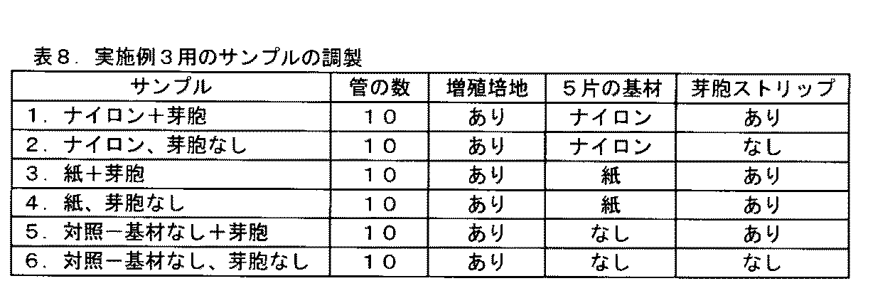
実施例2−培地の流れのフリック試験
以下の4つのセットの生物学的インジケーター(BI)サンプルを準備した。
Example 2 Media Flow Flick Test The following four sets of biological indicator (BI) samples were prepared.
実施例2A)上記の準備実施例で説明されるように、BIを準備した。 Example 2A) A BI was prepared as described in the above preparation example.
実施例2B)上述のようにBIを準備したが、ただし、基材119内には、開口121が存在しないものとした。
Example 2B) A BI was prepared as described above, except that no
実施例2C)上述のようにBIを準備したが、ただし、基材としてワットマン紙*を使用し(ナイロンの代わりに)、基材内には、3.2mmの開口を含むものとした。*(Whatman Inc.USA(Piscataway,NJ)製の、Whatmanグレード1 Chrセルロースクロマトグラフィー用ペーパー)
実施例2D)上述のようにBIを準備したが、ただし、基材としてワットマン紙*を使用し、基材内には、開口が存在しないものとした。
Example 2C) BI was prepared as described above, except that Whatman paper * was used as the substrate (instead of nylon), and the substrate contained 3.2 mm openings. * (Whatman Inc. USA (Piscataway, NJ) Whatman Grade 1 Chr Cellulose Chromatography Paper)
Example 2D) BI was prepared as described above, except that Whatman paper * was used as the substrate and no openings were present in the substrate.
これらのフリック試験BIを、管保持器内に定置して、キャップを押し下げることによりBIを作動させ、液体増殖培地122を収容する、壊れやすい容器120を粉砕した。液体増殖培地122の移動を、目視検査によって評価した。培地が、検出チャンバ111内に完全に移動しなかった場合には(気泡の存在によって証明される)、単一の下向きの振盪によって、BIを「フリック」した。各フリックの後、再度、検出チャンバを目視検査した。全ての培地を検出チャンバに移動させ、全ての気泡を除去するために必要とされた、フリックの数を記録した。フリックの数が多いほど、検出チャンバ111への、液体増殖培地の流れが不十分であることを示す。結果を表7に示す。
These flick test BIs were placed in a tube holder and the BIs were activated by pressing down on the caps, and the
実施例3−液体培地からのブロモクレゾ−ルパープル(BCP)の基材吸着
水1リットル当り、17グラムの細菌用ペプトン、0.17グラムのL−アラニン、及び0.03グラムのブロモクレゾ−ルパープルpH指示薬染料からなる、芽胞増殖培地溶液を調製した。この栄養培地溶液のpHを、0.1Nの水酸化ナトリウムで、7.6に調節した。
Example 3 Substrate Adsorption of Bromocresol Purple (BCP) from Liquid Medium 17 grams of bacterial peptone, 0.17 grams of L-alanine, and 0.03 grams of bromocresol purple pH indicator per liter of water A spore growth medium solution consisting of a dye was prepared. The pH of the nutrient medium solution was adjusted to 7.6 with 0.1N sodium hydroxide.
60個のホウケイ酸ガラス管(12mL、VWR、カタログ#53283−802)のそれぞれに、1.0mLの調製済み増殖培地を添加して、ライナーなしキャップクロージャー(VWR、カタログ# 66010−680)で蓋をした。 To each of the 60 borosilicate glass tubes (12 mL, VWR, catalog # 53283-802), add 1.0 mL of prepared growth medium and cap with a linerless cap closure (VWR, catalog # 66010-680). Did.
2つの異なる基材材料を評価した:GE荷電ナイロン(GE Osmonics Labstore(Minnetonka,MN)より入手可能な、MAGNAPROBE、0.45マイクロメートル荷電ナイロン膜、品番NP0HY00010)、及び紙(Whatman Inc.USA(Piscataway,NJ)より入手可能な、Whatmanグレード1 Chrセルロースクロマトグラフィー用ペーパー)。 Two different substrate materials were evaluated: GE charged nylon (MAGNAPROBE, 0.45 micrometer charged nylon membrane, part number NP0HY00010, available from GE Osmonics Laboratories (Minnetonka, MN)) and paper (Whatman Inc. USA ( Whatman Grade 1 Chr cellulose chromatography paper available from Piscataway, NJ).
2つの基材材料のそれぞれの、20個のストリップを、4mm×10mmのサイズに切り出した。全てのストリップを、Propper CHEX−ALL II Instant Sealing Pouch(Propper,Manufacturing Inc.(Long Island City,NY))内に定置して、AMSCO滅菌器(Steris(Mentor,OH))内で、121℃の蒸気液体サイクルで、30分間、それらを滅菌することによって、予備滅菌した。 Twenty strips of each of the two substrate materials were cut to a size of 4 mm × 10 mm. All strips were placed in a Proper CHEX-ALL II Instant Sealing Pouch (Proper, Manufacturing Inc. (Long Island City, NY)) in an AMSCO sterilizer (Steris (Mentor, OH)) at 121 ° C. Pre-sterilized by sterilizing them in a vapor liquid cycle for 30 minutes.
これらの滅菌済みの基材ストリップを、パウチから無菌状態で取り出して、ガラス管に移動させ、20個の管のそれぞれにつき5つのナイロン基材のストリップ、及び異なる20個の管のそれぞれにつき5つの紙基材のストリップとした。 These sterilized substrate strips are aseptically removed from the pouch and transferred to glass tubes, 5 nylon substrate strips for each of the 20 tubes, and 5 for each of the 20 different tubes. A strip of paper substrate.
3M Companyより入手可能な、G.ステアロサーモフィルスの芽胞(ATCC 7953)を収容する、分解した蒸気滅菌器用3M ATTEST 1292 Rapid Readout Biological Indicatorから、芽胞ストリップを取得した。この芽胞ストリップを、それぞれ約6.4mm×6.4mmの、4等分に切り出し、表8に従って、また以下で更に説明するように、ガラス管に添加した。1292 ATTESTの芽胞ストリップの1片(6.4mm×6.4mm)を、それぞれが5片のナイロン基材及び増殖培地を収容する、10個のガラス管のそれぞれに添加した。芽胞ストリップの1片を、各管が5片のワットマン紙及び増殖培地を収容する、10個のガラス管のそれぞれに添加した。芽胞ストリップの1片を、各管が増殖培地のみを収容し、基材を収容しない、10個のガラス管のそれぞれに添加した。残りの30個の管である、5片のナイロン基材を収容する10個の管、5片の紙基材を収容する10個の管、及び基材を収容しない10個の管には、芽胞ストリップ片を添加しなかった。 Available from 3M Company, G.M. Spore strips were obtained from a disassembled 3M ATTEST 1292 Rapid Readout Biological Indicator for a steam sterilizer containing stearothermophilus spores (ATCC 7953). The spore strips were each cut into 4 equal pieces of about 6.4 mm x 6.4 mm and added to the glass tube according to Table 8 and as further described below. A piece of spore strip of 1292 ATTEST (6.4 mm x 6.4 mm) was added to each of 10 glass tubes, each containing 5 pieces of nylon substrate and growth medium. One piece of spore strip was added to each of 10 glass tubes, each tube containing 5 pieces of Whatman paper and growth medium. One piece of spore strip was added to each of 10 glass tubes, each tube containing only growth medium and no substrate. The remaining 30 tubes, 10 tubes containing 5 pieces of nylon substrate, 10 tubes containing 5 pieces of paper substrate, and 10 tubes containing no substrate, No spore strip pieces were added.
上記のサンプルのそれぞれのうちの、2つの管を、1分の時点で、以下の観察及び分析に関して選択した。管の中にある間のナイロン又は紙の基材材料の色と、周囲を取り囲む液体増殖培地の色とを、基材が培地よりも暗いか又は明るいかに関して比較した。増殖培地を収容するガラス管から取り出したときの、基材材料の色を、観察及び記録した。 Two tubes of each of the above samples were selected for the following observations and analysis at the 1 minute time point. The color of the nylon or paper substrate material while in the tube was compared to the color of the surrounding liquid growth medium with respect to whether the substrate was darker or lighter than the medium. The color of the substrate material as it was removed from the glass tube containing the growth medium was observed and recorded.
X−Rite 530P濃度計(X−Rite(Grand Rapids MI))を使用して、濃度測定読み取り値を取得する前に、ナイロン基材及び紙基材のストリップを管から取り出して、KIMWIPE(Kimberly−Clark)上に定置した。X−Rite 530P濃度計に対する光学濃度設定は、「V」フィルターの結果を提供する「色」に設定した。基材のΔEの結果に関して、選択されたPantone 2665U及びPantone 102Uと「比較」するように、X−Rite濃度計を設定した。CIE76色差式を使用して、各PantoneでのΔEを計算した。ΔEの値は、L*A*B色空間内での、測定された点から基準値のPantoneの色までの距離である。より低いΔEは、測定された色が、より基準値に近いことを示す。約2.5のΔEの値は、人間の眼が色を識別するための、ほぼ最小の閾値である。使用する2つの基準値は、Pantone 2665U(薄い紫色)、及びPantone 102U(明るい黄色)とした。これらの2つの値は、「色相環」上で正反対に位置するものではないため、2665UでのΔEの増大が、必ずしも102UでのΔEの正確な減少を意味するものではないことに留意されたい。換言すれば、2665UでのΔEは、「紫色」に対する変化を示すのみであり、その一方、102UでのΔEは、「黄色」に対する変化を示すのみである。 Prior to taking densitometric readings using an X-Rite 530P densitometer (X-Rite (Grand Rapids MI)), the nylon and paper substrate strips were removed from the tube and KIMWIPE (Kimberly- Clark). The optical density setting for the X-Rite 530P densitometer was set to “color” which provides the result of the “V” filter. The X-Rite densitometer was set to “compare” with the selected Pantone 2665U and Pantone 102U for substrate ΔE results. The ΔE at each Pantone was calculated using the CIE 76 color difference equation. The value of ΔE is the distance from the measured point to the standard Pantone color in the L * A * B color space. A lower ΔE indicates that the measured color is closer to the reference value. A value of ΔE of about 2.5 is an approximately minimum threshold for the human eye to distinguish colors. The two reference values used were Pantone 2665U (light purple) and Pantone 102U (light yellow). Note that these two values are not exactly opposite on the “Hue Ring”, so an increase in ΔE at 2665U does not necessarily mean an exact decrease in ΔE at 102U. . In other words, ΔE at 2665U only shows a change for “purple”, while ΔE at 102U only shows a change for “yellow”.
各管内の培地の色もまた、観察及び記録した。3重に、各管から200μLの量の培地を取り出して、96ウェルプレート(透明な底部を有する、黒色の組織培養処理96ウェルプレート、COSTAR CLS−3603−48EA)内に定置し、Gen 5ソフトウェアでSYNERGY 4分光光度計を使用して、590nm及び430nmでの光学濃度を測定した。光学濃度(OD)の測定値は、モノクロメーター(BioTek(Winooski,VT))を使用して取得した。 The color of the medium in each tube was also observed and recorded. In triplicate, remove 200 μL of medium from each tube and place in a 96-well plate (black tissue culture treated 96-well plate with clear bottom, COSTAR CLS-3603-48EA) and Gen 5 software The optical density at 590 nm and 430 nm was measured using a SYNERGY 4 spectrophotometer. Optical density (OD) measurements were obtained using a monochromator (BioTek (Winooski, VT)).
残りの管を、56℃でインキュベートした。30分、1時間、4時間、及び24時間のインキュベーションの、それぞれの時間で、各サンプルのうちの2つの管をインキュベーターから取り出して、目視観察し、かつ上述のように計器測定した。 The remaining tubes were incubated at 56 ° C. At each time of 30 minutes, 1 hour, 4 hours, and 24 hours of incubation, two tubes of each sample were removed from the incubator, visually observed, and instrumented as described above.
全てのバイアル瓶内の培地は、4時間の読み取り後までは、紫色に維持された。芽胞を有さないサンプルは、24時間後も紫色に維持された。芽胞を有する全てのサンプルは、ブロモクレゾールパープル(BCP)pH指示薬染料が、紫色から黄色に変化することによって示される、培地のpHの減少をもたらす細胞の増殖により、24時間までには、視覚的に黄色に変化した。 The media in all vials remained purple until after 4 hours reading. Samples without spores remained purple after 24 hours. All samples with spores are visible by 24 hours due to cell growth resulting in a decrease in the pH of the medium as indicated by the bromocresol purple (BCP) pH indicator dye changing from purple to yellow. Turned yellow.
それぞれの時間間隔で、培地から基材を取り出す前に、基材の色を、培地の色と比較した。基材の色と培地の色との、相対的差異を報告した。基材としてナイロン基材を使用した、全ての場合で、基材は、周囲の培地よりも暗い色合いを呈した。基材として紙を使用した、全ての場合で、基材は、周囲の培地よりも明るい色合いを呈した。これらの結果は、指示試薬を受容及び濃縮する点で、ナイロン基材が、紙基材よりも優れていることを示す。 At each time interval, the color of the substrate was compared to the color of the medium before removing the substrate from the medium. The relative difference between substrate color and media color was reported. In all cases where a nylon substrate was used as the substrate, the substrate exhibited a darker shade than the surrounding medium. In all cases where paper was used as the substrate, the substrate exhibited a lighter shade than the surrounding medium. These results indicate that the nylon substrate is superior to the paper substrate in receiving and concentrating the indicator reagent.
殆どの場合、「暗い」とは、基材が培地よりも視覚的に暗い紫色であることを意味したが、24時間の、芽胞を有するナイロンは、例外として、より暗い黄色であった。殆どの場合、「明るい」とは、基材が培地よりも視覚的に明るい紫色であることを意味したが、24時間の、芽胞を有する紙は、例外として、より明るい黄色であった。 In most cases, “dark” meant that the substrate was a visibly darker purple than the medium, with the exception that the 24 hour nylon with spores was a darker yellow. In most cases, “bright” meant that the substrate was visibly lighter purple than the medium, with the exception that the 24 hour paper with spores was a lighter yellow.
芽胞を有するサンプルに関しては、24時間での、590nmでの光学濃度(OD)測定値は、黄色の強度の差異を示すものではない。それゆえ、24時間での、430nmで取得されたOD値のみを評価した。 For samples with spores, the optical density (OD) measurement at 590 nm at 24 hours does not indicate a difference in yellow intensity. Therefore, only the OD value obtained at 430 nm at 24 hours was evaluated.
紙基材の存在下での、芽胞を有する培地サンプル、及び芽胞を有し、基材を有さない培地サンプル(対照)の、24時間の430nmでの読み取り値は、双方とも、表11に示すように、それぞれ、0.827及び0.835の、同様のODの値を有する。しかしながら、ナイロンの存在下での、芽胞を有する培地サンプルは、対照又は紙基材を有するサンプルよりも0.5OD単位小さい、わずか0.271のODを有するものであった。このことは、ナイロンの存在下での培地の黄色の強度が、指示試薬を受容及び濃縮するナイロン基材により、低減されたことを示す。 The 24 hour reading at 430 nm for the media sample with spores and the media sample with and without spores in the presence of the paper substrate (control) are both in Table 11 As shown, it has similar OD values of 0.827 and 0.835, respectively. However, the media sample with spores in the presence of nylon had an OD of only 0.271, 0.5 OD units smaller than the sample with the control or paper substrate. This indicates that the yellow strength of the medium in the presence of nylon was reduced by the nylon substrate receiving and concentrating the indicator reagent.
1分での、基材を有さない対照(芽胞あり及び芽胞なし)の吸光度を、培地に関する初期ベースラインOD測定値と見なした。表12は、1分の時点でさえ、ナイロンの存在下での、芽胞を有するサンプル培地の、590nmでのOD(1.124)が、芽胞を有する、紙の存在下でのサンプル培地のOD(1.404)、又は芽胞を有する対照(1.402)よりも低いものであったことを示す。この差異は、培地の紫色の強度が、BCP指示試薬を急速に受容及び濃縮するナイロン基材により、既に低減されたことを示す。24時間での、ナイロンの存在下での、芽胞を有さないサンプル培地の、590nmでのODは、紙の存在下での培地のOD(1.708)、又は芽胞を有さない対照サンプルのOD、1.812よりも遙かに低い、1.122であった。 The absorbance of the control without substrate (with and without spores) at 1 minute was taken as the initial baseline OD measurement for the medium. Table 12 shows that even at 1 minute, the OD at 590 nm (1.124) of the sample medium with spores in the presence of nylon is the OD of the sample medium in the presence of paper with spores. (1.404) or lower than the control with spores (1.402). This difference indicates that the purple color intensity of the medium was already reduced by the nylon substrate that rapidly receives and concentrates the BCP indicator reagent. The OD at 590 nm of the sample medium without spore in the presence of nylon at 24 hours is the OD of the medium in the presence of paper (1.708), or the control sample without spore. The OD was 1.122, much lower than 1.812.
表13〜16は、様々な長さの時間にわたって、培地(芽胞あり及び芽胞なし)に晒した後の、基材の濃度測定読み取り値を示す。各基材に関する、時間0の読み取り値は、基材サンプルを培地中に定置する前の、初期濃度測定読み取り値である。紫色である基材を評価する場合、Vフィルター及びΔE(Pantone 2665U)が、最大の対比を示すものであった。ナイロン基材に関する、Vフィルターでの平均濃度測定読み取り値は、表14に示すように、実験全体を通して上昇し、高いまま維持された(唯一の例外は、「芽胞あり」のサンプルに関して、基材が24時間の時点で黄色であったときである)。対照的に、紙基材に関する濃度測定読み取り値は、それらの時点の全体にわたって、ほぼ一定のまま維持された。同様に、表15に示す、ナイロン基材のΔE(Pantone 2665U)の値は、実験全体を通して、概して減少した(唯一の例外は、「芽胞あり」のサンプルに関して、基材が24時間の時点で黄色であったときである)。このことは、ナイロン基材が、BCP指示試薬を受容及び濃縮していることを示すものであった。一方で、対照的に、紙基材に関するΔE(Pantone 2665U)の値は、ほぼ一定のまま維持された。
Tables 13-16 show substrate concentration measurement readings after exposure to media (with and without spores) for various lengths of time. The
表16は、24時間の時点で、ナイロン基材に関するΔE(Pantone 102U)の値が、紙基材に関するE(Pantone 102U)の値よりも大幅に低いものであったことを示し、ナイロン基材が、紙基材よりもpantone 102Uの色に近いもの(より明るい黄色)であったことを示す。 Table 16 shows that at 24 hours, the ΔE (Pantone 102U) value for the nylon substrate was significantly lower than the E (Pantone 102U) value for the paper substrate. Is closer to the color of pantone 102U than the paper substrate (lighter yellow).
実施例4−2回の24時間のインキュベーション後の、液体培地からの、ナイロン基材のBCPの吸着
実施例3で使用したものと同じ培地及び構成要素を、実施例4で使用した。4つのガラス管のそれぞれに、1.0mLの調製済み増殖培地を添加した。1292 ATTESTの芽胞ストリップの1片を、約6.4mm×6.4mmに切り出して、各ガラス管に添加した。これらの管を、インキュベーター内に、56℃で24時間定置して、G.ステアロサーモフィルス細胞の増殖を助長させた。24時間のインキュベーションの後、ナイロン基材の5つ(5)のストリップ(それぞれ4mm×10mmに切り出す)を、2つの管に添加した。残りの他の2つの対照の管には、ナイロン基材材料は添加しないものとした。これらの管を、インキュベーター内に、56℃で更に24時間定置した。管に対する2回目の24時間のインキュベーション期間の後(ナイロン基材の添加の24時間後)、以下の分析を実行した:(1)各管から、200μLの培地の3つのアリコートを採取し、96ウェルプレート内に定置して、それらの培地の430nmでの光学濃度を、SYNERGY 4分光光度計を再び使用して測定し;(2)ナイロン基材片を管から取り出し、KIMWIPE上に定置して吸い取り乾燥させ、X−Rite 530P濃度計で、基材ストリップの濃度測定読み取り値を取得した。
Example 4-Adsorption of nylon-based BCP from liquid medium after two 24 hour incubations The same medium and components used in Example 3 were used in Example 4. To each of the four glass tubes, 1.0 mL of prepared growth medium was added. A piece of 1292 ATTEST spore strip was cut to approximately 6.4 mm x 6.4 mm and added to each glass tube. These tubes were placed in an incubator at 56 ° C. for 24 hours. Promoted the growth of stearothermophilus cells. After 24 hours of incubation, five (5) strips of nylon substrate (each cut to 4 mm × 10 mm) were added to the two tubes. Nylon substrate material was not added to the other two control tubes. These tubes were placed in an incubator at 56 ° C. for an additional 24 hours. After the second 24 hour incubation period on the tubes (24 hours after the addition of the nylon substrate), the following analysis was performed: (1) Three aliquots of 200 μL of medium were taken from each tube and 96 Place in a well plate and measure the optical density of those media at 430 nm using the SYNERGY 4 spectrophotometer again; (2) Remove the nylon substrate piece from the tube and place on the KIMWIPE. Absorb and dry and take a density reading on the substrate strip with an X-Rite 530P densitometer.
表17は、ナイロン基材を管に添加した24時間後の培地の、基材を添加しなかった対照と比較した、430nmでのODの減少を示す。2つのサンプルの間のOD測定値の差異は、サンプル培地中に存在する黄色の量の差異を示す。このことは、ナイロンの存在下での、培地の黄色の強度が、指示試薬を受容及び濃縮するナイロン基材により、低減されたことを示す。 Table 17 shows the decrease in OD at 430 nm of the medium 24 hours after the nylon substrate was added to the tube, compared to the control with no substrate added. The difference in the OD measurement between the two samples indicates the difference in the amount of yellow present in the sample medium. This indicates that the yellow strength of the medium in the presence of nylon was reduced by the nylon substrate receiving and concentrating the indicator reagent.
表18は、既に24時間インキュベートされていた、芽胞を有する培地の管に、添加された24時間後の、ナイロン基材のΔE(102U)の値を示す。この値を、培地中に定置しなかったナイロン基材と比較した。2つのサンプルの間のΔE測定値の差異は、芽胞を有する(黄色の)培地に晒された基材の色が、培地に晒されなかった基材よりもpantone 102U(明るい黄色)に近いことを示す。換言すれば、ナイロン基材は、2回の24時間のインキュベーション及び増殖の期間後の、指示試薬の受容及び濃縮が、依然として可能であった。 Table 18 shows the value of ΔE (102 U) of the nylon substrate 24 hours after being added to the tube of culture medium with spores that had already been incubated for 24 hours. This value was compared to a nylon substrate that was not placed in the medium. The difference in ΔE measurements between the two samples is that the color of the substrate exposed to the spore-containing (yellow) medium is closer to pantone 102U (bright yellow) than the substrate not exposed to the medium. Indicates. In other words, the nylon substrate was still capable of receiving and concentrating the indicator reagent after two 24 hour incubation and growth periods.
実施例5−様々な基材材料による、液体培地からのBCPの吸着
水1リットル当り、17グラムの細菌用ペプトンC、0.17グラムのL−アラニン、及び0.03グラムのブロモクレゾ−ルパープル(BCP)pH指示薬染料からなる、芽胞増殖培地溶液を調製した。この栄養培地溶液のpHを、0.1Nの水酸化ナトリウムで、7.6に調節した。
Example 5-Adsorption of BCP from liquid media by various substrate materials 17 grams of bacterial peptone C, 0.17 grams of L-alanine and 0.03 grams of bromocresol purple per liter of water ( A spore growth medium solution consisting of BCP) pH indicator dye was prepared. The pH of the nutrient medium solution was adjusted to 7.6 with 0.1N sodium hydroxide.
ホウケイ酸ガラス管(12mL、VWR、カタログ#53283−802)のそれぞれに、1.0mLの調製済み増殖培地を添加して、ライナーなしキャップクロージャー(VWR、カタログ# 66010−680)で蓋をした。 To each borosilicate glass tube (12 mL, VWR, catalog # 53283-802), 1.0 mL of prepared growth medium was added and capped with a linerless cap closure (VWR, catalog # 66010-680).
4つの異なる基材材料を評価した:(1)GE荷電ナイロン(GE Osmonics Labstore(Minnetonka,MN)より入手可能な、MAGNAPROBE、0.45マイクロメートル荷電ナイロン膜、品番NP0HY00010);(2)第4級アミン基でプラスに荷電した、BIO−RAD高強度ナイロン膜(BIO−RAD LifeSciences(Hercules,CA)より入手可能な、ZETA−PROBE GT Genomics、カタログ#162−0196);(3)0.2μMのニトロセルロース(Invitrogen Corporation(Carlsbad,CA)より入手可能、カタログ# LC−2000)、及び(4)0.2μMの二フッ化ポリビニリデン(PVDF)膜(Invitrogen Corporation(Carlsbad,CA)より入手可能、カタログ# LC−2002)。基材材料のそれぞれの、幾つかのストリップを、各ガラス管に関する1つ(1)のストリップにとって十分な、4mm×10mmのサイズに切り出した。 Four different substrate materials were evaluated: (1) GE charged nylon (MAGNAPROBE, 0.45 micrometer charged nylon membrane, part number NP0HY00010, available from GE Osmonics Laboratories, Minnetonka, MN); (2) No. 4 BIO-RAD high-strength nylon membrane (ZETA-PROBE GT Genomics, catalog # 162-0196, available from BIO-RAD LifeSciences, Hercules, CA), positively charged with a secondary amine group; (3) 0.2 μM Nitrocellulose (available from Invitrogen Corporation (Carlsbad, Calif., Catalog # LC-2000)), and (4) 0.2 μM polyvinylidene difluoride (PVDF) membrane ( nvitrogen Corporation (Carlsbad, CA) available from, catalog # LC-2002). Several strips of each of the substrate materials were cut to a size of 4 mm × 10 mm, sufficient for one (1) strip for each glass tube.
全てのストリップを、Propper CHEX−ALL II Instant Sealing Pouch(Propper,Manufacturing Inc.(Long Island City,NY))内に定置して、AMSCO滅菌器(Steris(Mentor,OH))内で、蒸気液体サイクル(121℃での)で30分間、それらを滅菌することによって、予備滅菌した。 All strips are placed in a Proper CHEX-ALL II Instant Sealing Pouch (Proper, Manufacturing Inc. (Long Island City, NY)) in an AMSCO sterilizer (Steris (Mentor, OH)) in a steam liquid cycle. Pre-sterilized by sterilizing them (at 121 ° C.) for 30 minutes.
次いで、それらのストリップを、各管に無菌状態で移動させた。各基材の2つの管を、基材を収容しない2つの対照の管と共に評価した。 The strips were then transferred aseptically to each tube. Two tubes on each substrate were evaluated along with two control tubes that did not contain the substrate.
以下の観察及び分析を、0時間、30分、1時間、4時間、及び24時間の時点で実行した:(1)各管内の基材材料の色を、同じ管の周囲の培地の色と比較して、基材が周囲の培地よりも暗いか、又は明るいかを判定し、(2)基材材料を管から取り出し、KIMWIPE上に定置して吸い取り乾燥させ、次いで上述のように、Vフィルターで濃度測定読み取り値を取得し、(3)各管から200μLの培地を取り出して、96ウェルプレート(透明な底部を有する、黒色の組織培養処理96ウェルプレート、COSTAR CLS−3603−48EA)内へと、3重に移動させ、Gen 5ソフトウェアでSYNERGY 4分光光度計を使用して、590nmでの培地の光学濃度を測定した。光学濃度(OD)の測定値は、モノクロメーター(BioTek(Winooski,VT))を使用して取得した。 The following observations and analyzes were performed at 0, 30 minutes, 1 hour, 4 hours, and 24 hours: (1) The color of the substrate material in each tube is the color of the medium surrounding the same tube In comparison, determine whether the substrate is darker or brighter than the surrounding medium, and (2) remove the substrate material from the tube, place it on the KIMWIPE and blot dry, then, as described above, V Concentration readings were obtained with a filter, (3) 200 μL of medium was removed from each tube and placed in a 96-well plate (black tissue culture treated 96-well plate with clear bottom, COSTAR CLS-3603-48EA) The optical density of the medium at 590 nm was measured using a SYNERGY 4 spectrophotometer with Gen 5 software. Optical density (OD) measurements were obtained using a monochromator (BioTek (Winooski, VT)).
残りの管を、56℃でインキュベートした。30分、1時間、4時間、及び24時間のインキュベーションの、それぞれの時間で、各サンプルのうちの2つの管を、インキュベーターから取り出して、目視観察し、かつ上述のように計器測定した。 The remaining tubes were incubated at 56 ° C. At each time of 30 minutes, 1 hour, 4 hours, and 24 hours incubation, two tubes of each sample were removed from the incubator, visually inspected, and instrumented as described above.
それぞれの読み取りで、基材を培地から取り出す前に、培地の色を、基材の色と視覚的に比較した。基材の色と培地の色との差異を観察して、上記の表内に報告した。培地との接触の30分後に、ナイロン基材材料は、双方とも培地よりも視覚的に暗いものとなり、実験全体を通して、より暗いまま維持された。 At each reading, the media color was visually compared to the substrate color before the substrate was removed from the media. The difference between the color of the substrate and the color of the medium was observed and reported in the table above. After 30 minutes of contact with the medium, both nylon substrate materials were visually darker than the medium and remained darker throughout the experiment.
上記の表は、様々な長さの時間にわたって培地に晒された後の、基材材料の濃度測定読み取り値を示す。各基材に関する、時間0の読み取り値は、培地中に定置されている基材の、30秒以内の初期濃度測定読み取り値である。全ての場合で、ナイロン基材の濃度測定読み取り値は、30分以内で上昇し、実験全体を通して高いまま維持された。
The above table shows the concentration measurement readings of the substrate material after being exposed to the medium for various lengths of time. The
表21は、各基材材料を収容する管から、特定の時間で取り出された培地の、平均光学濃度(OD)読み取り値を示す。各時点で、いずれのナイロン基材の存在下にあった培地に関するODも、ニトロセルロース又はPVDFのいずれかを含む培地に関するOD読み取り値よりも、低いものであったことに注目するべきである。更には、ニトロセルロース又はPVDFは、OD読み取り値の変化を殆ど示すことなく、対照のODの値に極めて類似している。 Table 21 shows the average optical density (OD) readings of media removed at specific times from tubes containing each substrate material. It should be noted that at each time point, the OD for medium that was in the presence of any nylon substrate was lower than the OD reading for medium containing either nitrocellulose or PVDF. Furthermore, nitrocellulose or PVDF is very similar to the OD value of the control with little change in OD reading.
実施例6−ナイロン基材による、液体培地からのメチルレッドの吸着
水1リットル当り、17グラムの細菌用ペプトン、0.17グラムのL−アラニン、及び0.03グラムのメチルレッドpH指示薬染料からなる、芽胞増殖培地溶液を調製した。この栄養培地溶液のpHを、0.1Nの塩酸で、4.2に調節した。
Example 6 Adsorption of Methyl Red from Liquid Medium by Nylon Base From 17 grams of bacterial peptone, 0.17 grams of L-alanine, and 0.03 grams of methyl red pH indicator dye per liter of water A spore growth medium solution was prepared. The pH of this nutrient medium solution was adjusted to 4.2 with 0.1N hydrochloric acid.
ホウケイ酸ガラス管(12mL、VWR、カタログ#53283−802)のそれぞれに、1.0mLの調製済み増殖培地を添加して、ライナーなしキャップクロージャー(VWR、カタログ# 66010−680)で蓋をした。 To each borosilicate glass tube (12 mL, VWR, catalog # 53283-802), 1.0 mL of prepared growth medium was added and capped with a linerless cap closure (VWR, catalog # 66010-680).
2つの異なる基材材料を評価した:GE荷電ナイロン(GE Osmonics Labstore(Minnetonka,MN)より入手可能な、MAGNAPROBE、0.45マイクロメートル荷電ナイロン膜、品番NP0HY00010);第4級アミン基でプラスに荷電した、BIO−RAD高強度ナイロン膜(BIO−RAD LifeSciences(Hercules,CA)より入手可能な、ZETA−PROBE GT Genomics、カタログ#162−0196)。基材材料のそれぞれの、幾つかのストリップを、各ガラス管に関する1つ(1)のストリップにとって十分な、4mm×10mmのサイズに切り出した。 Two different substrate materials were evaluated: GE charged nylon (MAGNAPROBE, 0.45 micrometer charged nylon membrane, part number NP0HY00010, available from GE Osmonics Laboratories, Minnetonka, MN); plus quaternary amine groups plus Charged, BIO-RAD high strength nylon membrane (ZETA-PROBE GT Genomics, catalog # 162-0196, available from BIO-RAD LifeSciences, Hercules, CA). Several strips of each of the substrate materials were cut to a size of 4 mm × 10 mm, sufficient for one (1) strip for each glass tube.
全てのストリップを、Propper CHEX−ALL II Instant Sealing Pouch(Propper,Manufacturing Inc.(Long Island City,NY))内に定置して、AMSCO滅菌器(Steris(Mentor,OH))内で、蒸気液体サイクル(121℃での)で30分間、それらを滅菌することによって、予備滅菌した。 All strips are placed in a Proper CHEX-ALL II Instant Sealing Pouch (Proper, Manufacturing Inc. (Long Island City, NY)) in an AMSCO sterilizer (Steris (Mentor, OH)) in a steam liquid cycle. Pre-sterilized by sterilizing them (at 121 ° C.) for 30 minutes.
次いで、それらのストリップを、各管に無菌状態で移動させた。 The strips were then transferred aseptically to each tube.
以下の観察及び分析を、各基材の2つの管に関して、0時間、30分、1時間、4時間、及び24時間の時点で実行した:(1)基材材料を管から取り出し、KIMWIPE上に定置して吸い取り乾燥させ、次いで上述のように、Vフィルターで濃度測定読み取り値を取得し、(2)各管内の基材材料の色を、同じ管の周囲の培地の色と比較して、基材が周囲の培地よりも暗いか、又は明るいかを判定した。 The following observations and analyzes were performed on the two tubes of each substrate at 0 hour, 30 minutes, 1 hour, 4 hours, and 24 hours: (1) The substrate material was removed from the tube and on the KIMWIPE And then suck and dry, and then, as described above, take a concentration measurement reading with a V-filter, and (2) compare the color of the substrate material in each tube with the color of the medium surrounding the same tube The substrate was determined to be darker or lighter than the surrounding medium.
残りの管を、56℃でインキュベートした。30分、1時間、4時間、及び24時間のインキュベーションの、それぞれの時間で、各サンプルのうちの2つの管を、インキュベーターから取り出して、目視観察し、かつ上述のように計器測定した。 The remaining tubes were incubated at 56 ° C. At each time of 30 minutes, 1 hour, 4 hours, and 24 hours incubation, two tubes of each sample were removed from the incubator, visually inspected, and instrumented as described above.
表22は、様々な長さの時間にわたって培地に晒された後の、ナイロン基材材料の濃度測定読み取り値を示す。各基材に関する、時間0の読み取り値は、培地中に定置されている基材の、30秒以内の初期濃度測定読み取り値である。全ての場合で、ナイロン基材の濃度測定読み取り値は、30分以内で上昇し、実験全体を通して高いまま維持された。
Table 22 shows the nylon substrate material concentration measurement readings after exposure to the medium for various lengths of time. The
それぞれの読み取りで、基材材料を培地から取り出す前に、培地の色を、基材の色と比較した。基材の色と培地の色との差異を、観察及び報告した。培地との接触の30分後に、ナイロン基材材料は、双方とも培地よりも視覚的に暗いものとなり、実験全体を通して、より暗いまま維持された。 At each reading, the media color was compared to the substrate color before the substrate material was removed from the media. Differences in substrate color and media color were observed and reported. After 30 minutes of contact with the medium, both nylon substrate materials were visually darker than the medium and remained darker throughout the experiment.
実施例7−ブロモクレゾ−ルパープル(BCP)の吸光度スペクトル
Sigma Chemical Co.(St.Louis,MO)より得たブロモクレゾ−ルパープル(BCP)(カタログ番号B−5880)を、pH 7.3のリン酸緩衝生理食塩水中に、0.004の濃度で溶解させた。この溶液を、石英キュベット内に定置し、TECAN Infinity M200 Plate Reader(Tecan US(Durham,NC))に提供される、1cmキュベットアダプターを使用して、UV−可視吸光度スペクトルを走査した。この走査パラメーターを、表24に提示する。
Example 7-Absorbance spectrum of bromocresol purple (BCP) Sigma Chemical Co. Bromocresol purple (BCP) (Catalog No. B-5880) obtained from (St. Louis, MO) was dissolved in phosphate buffered saline at pH 7.3 at a concentration of 0.004. This solution was placed in a quartz cuvette and scanned for UV-visible absorbance spectra using a 1 cm cuvette adapter provided by TECAN Infinity M200 Plate Reader (Tecan US (Durham, NC)). The scan parameters are presented in Table 24.
結果を、図8に示されるグラフで示す。吸光度のピークは、約300nm、約380nm、及び約600nmの波長で認めることができる。 The results are shown in the graph shown in FIG. Absorbance peaks can be seen at wavelengths of about 300 nm, about 380 nm, and about 600 nm.
実施例8−;7−ヒドロキシ−4−メチルクマリン(4−メチルウンベリフェロン)の発光スペクトル
Sigma Chemical Co.(St.Louis,MO)より得た、4−メチルウンベリフェロン(4MU)、カタログ番号m1381を、pH 7.3のリン酸緩衝生理食塩水中に、0.004mg/mLの濃度で溶解させた。この溶液を、石英キュベット内に定置し、TECAN Infinity M200 Plate Readerに提供される、1cmキュベットアダプターを使用して、発光スペクトルを記録した。この走査パラメーターを、表25に提示する。
Example 8-; Emission spectrum of 7-hydroxy-4-methylcoumarin (4-methylumbelliferone) Sigma Chemical Co. 4-Methylumbelliferone (4MU), catalog number m1381, obtained from (St. Louis, MO), was dissolved in phosphate buffered saline at pH 7.3 at a concentration of 0.004 mg / mL. . This solution was placed in a quartz cuvette and the emission spectrum was recorded using a 1 cm cuvette adapter provided to the TECAN Infinity M200 Plate Reader. The scan parameters are presented in Table 25.
結果を、図8に示されるグラフで示す。発光のピークは、約450nmの波長で認めることができる。 The results are shown in the graph shown in FIG. The emission peak can be observed at a wavelength of about 450 nm.
実施例9−4MUの検出に対するBCPの影響
実施例8で説明されるように調製した、4−メチルウンベリフェロン(4MU)の原液を、リン酸緩衝生理食塩水中に、表26に示す濃度まで、段階希釈した。ブロモクレゾ−ルパープル(BCP)の原液を、実施例7で説明されるように、リン酸緩衝生理食塩水中に調製した。このブロモクレゾ−ルパープル(0.03mg/mLの最終濃度)を、表26に示す、4MUのそれぞれの溶液と混合した。それぞれの溶液の各3部のアリコート(100マイクロリットル/ウェル)を、96ウェルプレート内に装填し、TECAN Infinity M200 Plate Readerを使用して、各ウェル内での蛍光を測定した。励起波長は350nmとし、検出は420nmとした。相対蛍光単位(RFU)として列挙される結果を、表26に示す。このデータは、試験された4MUのあらゆる濃度で、溶液中のブロモクレゾ−ルパープルの存在が、測定可能な蛍光の減少をもたらしたことを示す。
Example 9-4 Effect of BCP on Detection of MU A stock solution of 4-methylumbelliferone (4MU), prepared as described in Example 8, was added in phosphate buffered saline to the concentrations shown in Table 26. Serially diluted. Bromocresol purple (BCP) stock solution was prepared in phosphate buffered saline as described in Example 7. This bromocresol purple (0.03 mg / mL final concentration) was mixed with each 4 MU solution shown in Table 26. Three aliquots (100 microliters / well) of each solution were loaded into 96 well plates and fluorescence in each well was measured using a TECAN Infinity M200 Plate Reader. The excitation wavelength was 350 nm and the detection was 420 nm. The results listed as relative fluorescence units (RFU) are shown in Table 26. This data shows that at every concentration of 4 MU tested, the presence of bromocresol purple in solution resulted in a measurable decrease in fluorescence.
この結果は、3部の複製の平均である。全ての値は、相対蛍光単位(RFU)で報告される。 This result is an average of three copies. All values are reported in relative fluorescence units (RFU).
実施例10−BCP及びメチルレッドでの、アクリジンオレンジ検出の阻害
17グラムの細菌用ペプトン、0.17グラムのL−アラニンからなる、芽胞増殖培地溶液を調製した。200マイクロリットル(μL)の容積の、この増殖培地を、2つの96ウェルプレート内の各ウェルに添加した。
Example 10-Inhibition of acridine orange detection with BCP and methyl red A spore growth medium solution consisting of 17 grams of bacterial peptone, 0.17 grams of L-alanine was prepared. A volume of 200 microliters (μL) of this growth medium was added to each well in two 96 well plates.
4.8g/Lから開始して0.75g/Lまで希釈される、pH指示薬溶液の希釈系列を、メチルレッド(MR)及びブロモクレゾ−ルパープル(BCP)の双方に関して作製した。1:50から開始して1:800まで希釈される、アクリジンオレンジの希釈系列を作製した。 A dilution series of pH indicator solution starting at 4.8 g / L and diluted to 0.75 g / L was made for both methyl red (MR) and bromocresol purple (BCP). A dilution series of acridine orange was made starting from 1:50 and diluted to 1: 800.
プレート#1では、20μLの適切な希釈のBCPを、プレートの各横列に添加し、20μLの適切な希釈のアクリジンオレンジ(AO)を、プレート#1の各縦列に添加した。プレート#2では、20μLの適切な希釈のメチルレッドを、プレートの各横列に添加し、20μLの適切な希釈のアクリジンオレンジ(AO)を、プレート#2の各縦列に添加した。プレート#1及びプレート#2の設定に関しては、表27を参照されたい。 For plate # 1, 20 μL of the appropriate dilution of BCP was added to each row of the plate, and 20 μL of the appropriate dilution of acridine orange (AO) was added to each column of plate # 1. For plate # 2, 20 μL of the appropriate dilution of methyl red was added to each row of the plate, and 20 μL of the appropriate dilution of acridine orange (AO) was added to each column of plate # 2. See Table 27 for plate # 1 and plate # 2 settings.
プレート#1及びプレート#2を、SYNERGY 4分光光度計内に定置して、吸光度の読み取り値を、590nmで取得した。更には、435nm/530nmでの蛍光励起/発光の読み取り値もまた、収集した。 Plate # 1 and plate # 2 were placed in a SYNERGY 4 spectrophotometer and absorbance readings were taken at 590 nm. In addition, fluorescence excitation / emission readings at 435 nm / 530 nm were also collected.
全てのアクリジンオレンジの濃度に関して、溶液中のブロモクレゾ−ルパープルの量が減少するにつれて、アクリジンオレンジによって生成されるシグナルが増大した。換言すれば、BCPの存在は、アクリジンオレンジのシグナルを覆い隠すものであった。例えば、0.3g/Lの初期BCP濃度を有する横列に関しては、0のBCPを有する横列と比較して、約27〜36%のアクリジンオレンジの蛍光シグナルが失われる。 For all acridine orange concentrations, the signal produced by acridine orange increased as the amount of bromocresol purple in the solution decreased. In other words, the presence of BCP masked the acridine orange signal. For example, for a row with an initial BCP concentration of 0.3 g / L, about 27-36% acridine orange fluorescence signal is lost compared to a row with a BCP of 0.
BCPと同様に、メチルレッドもまた、アクリジンオレンジの蛍光シグナルを覆い隠すものであった。メチルレッドの濃度が高いほど、検出されるアクリジンオレンジの蛍光シグナルは低下する。例えば、0.3g/Lの初期メチルレッド濃度を有する横列に関しては、メチルレッドを有さない横列と比較して、約3〜27%のアクリジンオレンジの蛍光シグナルが失われる。 Like BCP, methyl red also masked the fluorescent signal of acridine orange. The higher the concentration of methyl red, the lower the detected acridine orange fluorescence signal. For example, for a row with an initial methyl red concentration of 0.3 g / L, about 3 to 27% of the acridine orange fluorescence signal is lost compared to a row without methyl red.
上述され、図に示される実施形態は、単なる例として提示されるものであり、本開示の概念及び原理に対する限定を意図するものではない。それゆえ、本開示の趣旨及び範囲から逸脱することなく、諸要素、並びにその構成及び配置の、様々な変更が可能であることが、当業者には理解されるであろう。本開示の様々な特徴及び態様を、以下の特許請求の範囲に記載する。 The embodiments described above and illustrated in the figures are presented by way of example only and are not intended as limitations on the concepts and principles of the present disclosure. Thus, it will be understood by one of ordinary skill in the art that various changes in the elements and their configuration and arrangement are possible without departing from the spirit and scope of the present disclosure. Various features and aspects of the disclosure are set forth in the following claims.
Claims (3)
液体を収容し、かつ前記ハウジング内に配置されるように寸法決めされる、容器であって、前記容器の少なくとも一部分が壊れやすく、前記容器は、前記容器が無損傷であり、前記液体が前記ハウジングの内部と流体連通していない、第1の状態と、前記容器が断裂して、前記液体が前記ハウジングの前記内部と流体連通する、第2の状態とを有する、容器と、
前記容器が前記第1の状態にあるとき、前記容器が中に配置される、前記ハウジング内の第1チャンバと、
前記容器が前記第1の状態にあるとき、前記容器及び前記液体が中に配置されない、前記ハウジング内の第2チャンバであって、前記第2チャンバは、前記容器が前記第1の状態にあるとき、前記液体と流体連通せず、前記容器が前記第2の状態にあるとき、前記液体と流体連通する、生物活性の発生源を含む、第2チャンバと、
前記ハウジング内で、前記第1チャンバと前記第2チャンバとの間に配置される基材であって、前記基材は、前記第1チャンバ及び前記第2チャンバと流体連通して配置され、前記基材は、前記基材が前記生物活性の発生源と直接接触しないように、更に配置される、基材と、
を含む、生物学的滅菌インジケーターであって、前記基材は、前記容器が前記第2の状態にあり、そして前記基材が指示試薬を含む液体と流体連通するときに、前記指示試薬を濃縮するように適合されている、生物学的滅菌インジケーター。 A housing;
A container that contains liquid and is sized to be disposed within the housing, wherein at least a portion of the container is fragile, the container is undamaged, and the liquid is A container having a first state that is not in fluid communication with the interior of the housing and a second state in which the container is torn and the liquid is in fluid communication with the interior of the housing;
A first chamber in the housing in which the container is disposed when the container is in the first state;
A second chamber within the housing, wherein the container and the liquid are not disposed therein when the container is in the first state, the second chamber being in the first state. A second chamber comprising a source of biological activity that is not in fluid communication with the liquid and is in fluid communication with the liquid when the container is in the second state;
A substrate disposed within the housing between the first chamber and the second chamber, the substrate disposed in fluid communication with the first chamber and the second chamber; A substrate, further disposed such that the substrate is not in direct contact with the source of biological activity;
A biological sterilization indicator , wherein the substrate concentrates the indicator reagent when the container is in the second state and the substrate is in fluid communication with a liquid containing the indicator reagent. A biological sterilization indicator that is adapted to .
Applications Claiming Priority (5)
| Application Number | Priority Date | Filing Date | Title |
|---|---|---|---|
| US40896610P | 2010-11-01 | 2010-11-01 | |
| US40897710P | 2010-11-01 | 2010-11-01 | |
| US61/408,966 | 2010-11-01 | ||
| US61/408,977 | 2010-11-01 | ||
| PCT/US2011/058257 WO2012061227A2 (en) | 2010-11-01 | 2011-10-28 | Biological sterilization indicator |
Publications (3)
| Publication Number | Publication Date |
|---|---|
| JP2013541400A JP2013541400A (en) | 2013-11-14 |
| JP2013541400A5 JP2013541400A5 (en) | 2014-11-13 |
| JP5934231B2 true JP5934231B2 (en) | 2016-06-15 |
Family
ID=44947232
Family Applications (3)
| Application Number | Title | Priority Date | Filing Date |
|---|---|---|---|
| JP2013536855A Active JP6178239B2 (en) | 2010-11-01 | 2011-10-28 | Detection method of biological activity |
| JP2013537727A Active JP5934231B2 (en) | 2010-11-01 | 2011-10-28 | Biological sterilization indicator |
| JP2016229668A Active JP6259052B2 (en) | 2010-11-01 | 2016-11-28 | Detection method of biological activity |
Family Applications Before (1)
| Application Number | Title | Priority Date | Filing Date |
|---|---|---|---|
| JP2013536855A Active JP6178239B2 (en) | 2010-11-01 | 2011-10-28 | Detection method of biological activity |
Family Applications After (1)
| Application Number | Title | Priority Date | Filing Date |
|---|---|---|---|
| JP2016229668A Active JP6259052B2 (en) | 2010-11-01 | 2016-11-28 | Detection method of biological activity |
Country Status (8)
| Country | Link |
|---|---|
| US (4) | US8802392B2 (en) |
| EP (2) | EP2635700B1 (en) |
| JP (3) | JP6178239B2 (en) |
| CN (3) | CN103201390B (en) |
| BR (1) | BR112013010096B1 (en) |
| CA (2) | CA2816459A1 (en) |
| ES (2) | ES2687181T3 (en) |
| WO (2) | WO2012061213A1 (en) |
Families Citing this family (45)
| Publication number | Priority date | Publication date | Assignee | Title |
|---|---|---|---|---|
| WO2012061229A1 (en) | 2010-11-01 | 2012-05-10 | 3M Innovative Properties Company | Biological sterilization indicator system and method |
| WO2012061228A1 (en) | 2010-11-01 | 2012-05-10 | 3M Innovative Properties Company | Biological sterilization indicator system and method |
| ES2671346T3 (en) | 2010-11-01 | 2018-06-06 | 3M Innovative Properties Company | Indicator of biological sterilization and method of use thereof |
| CN103201390B (en) * | 2010-11-01 | 2016-03-16 | 3M创新有限公司 | Detect bioactive method |
| US8975067B2 (en) * | 2010-12-22 | 2015-03-10 | 3M Innovative Properties Company | Self-contained sterilization indicators including a neutralizer for residual oxidizing sterilant |
| WO2014058673A1 (en) * | 2012-10-08 | 2014-04-17 | 3M Innovative Properties Company | An electronic indicator for monitoring efficacy of a cleaning cycle |
| US20140356900A1 (en) * | 2013-05-31 | 2014-12-04 | Empire Technology Development Llc | Detection of luminal urinary catheter colonization |
| US9535043B2 (en) | 2013-05-31 | 2017-01-03 | Empire Technology Development Llc | Color change indicator of biofilm formation |
| GB201319768D0 (en) * | 2013-11-08 | 2013-12-25 | Glycosynth Ltd | Naphthalene derived chromogenic enzyme substrates |
| BR112017007418A2 (en) * | 2014-10-10 | 2017-12-19 | 3M Innovative Properties Co | biological sterilization indicator with sterilizer resistance modulator |
| US9416393B2 (en) | 2014-10-13 | 2016-08-16 | American Sterilizer Company | Biological indicator |
| WO2016149571A1 (en) * | 2015-03-19 | 2016-09-22 | 3M Innovative Properties Company | Devices, methods, kits, and systems for detecting microorganism strains or target cellular analytes in a fluid sample |
| US20170119300A1 (en) * | 2015-10-29 | 2017-05-04 | Patrona Medical, Inc. | Sensor Management And Record Tracking System |
| JP6947733B2 (en) | 2016-01-25 | 2021-10-13 | アメリカン ステリライザー カンパニー | Capacitors for detecting viable microorganisms |
| US20170234847A1 (en) * | 2016-02-13 | 2017-08-17 | BacTrac Technologies LLC | Lanthanide-Doped Nanoparticle Compositions for Detecting Microorganisms |
| US10907126B2 (en) * | 2016-03-01 | 2021-02-02 | Asp Global Manufacturing Gmbh | Self-contained biological indicator |
| US11242505B2 (en) | 2017-01-03 | 2022-02-08 | Asp Global Manufacturing Gmbh | Self-contained biological indicator |
| US20180237821A1 (en) | 2017-02-23 | 2018-08-23 | Ethicon, Inc. | Apparatus and method to read biological indicator |
| US11053534B2 (en) | 2017-06-30 | 2021-07-06 | Asp Global Manufacturing Gmbh | Systems and methods for confirming activation of biological indicators |
| US10900062B2 (en) | 2017-07-14 | 2021-01-26 | American Sterilizer Company | Process for determining viability of test microorganisms of biological indicator and sterilization detection device for determining same |
| US10889848B2 (en) | 2017-07-14 | 2021-01-12 | American Sterilizer Company | Process for determining viability of test microorganisms of biological indicator and sterilization detection device for determining same |
| US10876144B2 (en) | 2017-07-14 | 2020-12-29 | American Sterilizer Company | Process for determining viability of test microorganisms of biological indicator and sterilization detection device for determining same |
| US10823715B2 (en) | 2017-07-19 | 2020-11-03 | American Sterilizer Company | Chemical indicator for monitoring hydrogen peroxide sterilization and disinfection processes |
| CN107505311A (en) * | 2017-09-25 | 2017-12-22 | 江苏中新医药有限公司 | The quick method and biological indicator for determining sterilization effect |
| US11248250B2 (en) * | 2017-12-01 | 2022-02-15 | Asp Global Manufacturing Gmb | Self-contained biological indicator |
| WO2019123217A1 (en) | 2017-12-19 | 2019-06-27 | 3M Innovative Properties Company | Methods to detect microorganisms |
| EP3752819B1 (en) * | 2018-02-15 | 2023-08-09 | ProciseDx Inc. | Analyzer |
| DE112019002443A5 (en) * | 2018-05-16 | 2021-02-04 | Seitz Hiemer Sogaro Gbr (Vertretungsberechtigte Gesellschafter: Andreas Hiemer, 22926 Ahrensburg; Alberto C. Sògaro, 61348 Bad Homburg; Sebastian Seitz, 91602 Dürrwangen) | APPLICATOR |
| US11579127B2 (en) * | 2018-06-29 | 2023-02-14 | Asp Global Manufacturing Gmbh | Apparatus, method, and system for indication of an oxidative treatment |
| CN112437676A (en) | 2018-07-27 | 2021-03-02 | 3M创新有限公司 | Self-contained biological indicator |
| US11850320B2 (en) | 2018-12-20 | 2023-12-26 | Asp Global Manufacturing Gmbh | Liquid-chemical sterilization system with biological indicator |
| WO2020136613A1 (en) | 2018-12-27 | 2020-07-02 | 3M Innovative Properties Company | Instant read-out biological indicator with growth confirmation |
| WO2020136608A1 (en) | 2018-12-27 | 2020-07-02 | 3M Innovative Properties Company | Instant read-out biological indicator |
| WO2020136462A1 (en) | 2018-12-28 | 2020-07-02 | Asp Global Manufacturing Gmbh | A treatment indicator, a method of production thereof, and a method of use thereof |
| US11884960B2 (en) | 2019-08-16 | 2024-01-30 | Terragene Llc | Biological indicator for determining the efficacy of a steam or heat sterilization process and its method of use |
| CN114981399A (en) | 2020-01-22 | 2022-08-30 | 3M创新有限公司 | Self-contained biological indicator with salt compound |
| US20230193347A1 (en) | 2020-04-22 | 2023-06-22 | 3M Innovative Properties Company | Biological Indicator with Test Microorganisms Enveloped by Wax Composition |
| WO2022049442A1 (en) * | 2020-09-02 | 2022-03-10 | 3M Innovative Properties Company | Biological indicator comprising genetically-modified test microorganism |
| EP4243885A1 (en) | 2020-11-10 | 2023-09-20 | Advanced Sterilization Products, Inc. | Ampoule breaker for a biological indicator |
| US11603551B2 (en) | 2020-12-02 | 2023-03-14 | Steritec Products Mfg. Co., Inc. | Biological indicators, and systems and methods for determining efficacy of sterilization |
| NO346360B1 (en) * | 2021-04-14 | 2022-06-27 | Cmeye As | Indicator for perishable products |
| US20230002802A1 (en) | 2021-07-02 | 2023-01-05 | Terragene Llc | Biological indicator for determining the efficacy of an oxidative sterilization process and methods of use |
| WO2023021348A1 (en) | 2021-08-18 | 2023-02-23 | 3M Innovative Properties Company | Device, system, and method for determining the efficacy of a sterilization process |
| WO2023043723A1 (en) * | 2021-09-14 | 2023-03-23 | Stratix Labs Corporation | Devices and methods for measuring efficacy of ultraviolet light disinfection |
| CN114410540B (en) * | 2022-02-07 | 2024-01-19 | 山东新华医疗器械股份有限公司 | Bacillus stearothermophilus culture solution for improving spore rate and culture method |
Family Cites Families (98)
| Publication number | Priority date | Publication date | Assignee | Title |
|---|---|---|---|---|
| US3814522A (en) | 1973-02-28 | 1974-06-04 | American Hospital Supply Corp | Specimen tube for microscopic examination |
| JPS53105477A (en) | 1977-02-26 | 1978-09-13 | Ajinomoto Co Inc | 7-glycylprolylamono-4-methylcoumarine |
| US4215047A (en) | 1977-06-06 | 1980-07-29 | Ajinomoto Company Incorporated | 7-(Arginylamino)-4-methylcoumarins |
| US4291122A (en) | 1980-08-14 | 1981-09-22 | American Sterilizer Company | Biological indicator for sterilization processes |
| US4565783A (en) | 1981-01-27 | 1986-01-21 | Minnesota Mining And Manufacturing Company | Dry culture media |
| US4461837A (en) | 1981-09-30 | 1984-07-24 | American Sterilizer Company | Contamination-free sterilization indicating system |
| US4528268A (en) | 1981-12-31 | 1985-07-09 | H. W. Andersen Products Inc. | Apparatus and method for testing the sufficiency of sterilization |
| US4528187A (en) | 1982-03-12 | 1985-07-09 | Truglio William J | Apparatus for collecting and microscopically examining a specimen |
| US4591566A (en) | 1983-11-25 | 1986-05-27 | Bio-Environmental Systems, Inc. | Biological indicator probe for steam sterilizing systems |
| CA1256360A (en) * | 1984-02-10 | 1989-06-27 | John W. Bornhoeft | Apparatus and method for determining the effectiveness of sterlization |
| US4732850A (en) | 1985-07-05 | 1988-03-22 | E. R. Squibb & Sons, Inc. | Frangible container with rupturing device |
| US4743537A (en) * | 1986-01-21 | 1988-05-10 | Castle Company | Biological indicator for sterilization processes |
| US5968807A (en) | 1987-06-29 | 1999-10-19 | Getinge/Castle, Inc. | Culture media containing glycerol that are pH and color stable when heat sterilized |
| JPH01107765A (en) * | 1987-10-19 | 1989-04-25 | Minsei Kagaku Kyokai | Sterilizing biological indicator |
| US5094955A (en) * | 1988-03-15 | 1992-03-10 | Akzo N.V. | Device and method for detecting microorganisms |
| AU616957B2 (en) | 1988-06-20 | 1991-11-14 | Becton Dickinson & Company | Device for enhancing fluorescence and kinetics and methods of using the device |
| US5223401A (en) | 1988-11-29 | 1993-06-29 | Minnesota Mining And Manufacturing Company | Rapid read-out sterility indicator |
| US5252484A (en) | 1988-11-29 | 1993-10-12 | Minnesota Mining And Manufacturing Company | Rapid read-out biological indicator |
| US5073488A (en) * | 1988-11-29 | 1991-12-17 | Minnesota Mining And Manufacturing Company | Rapid method for determining efficacy of a sterilization cycle and rapid read-out biological indicator |
| US4885253A (en) | 1989-03-27 | 1989-12-05 | Steris Corporation | Universal biological indicator system |
| US5089413A (en) | 1989-05-19 | 1992-02-18 | Minnesota Mining And Manufacturing Company | Method and apparatus for culturing with microbiological dry culture medium |
| US5167923A (en) | 1989-09-28 | 1992-12-01 | Pymah Corporation | Sterility indicator |
| AU1915892A (en) * | 1991-05-08 | 1992-12-21 | Baxter Diagnostics Inc. | Method and apparatus to detect bacterial contamination of transfusable blood |
| US5316906A (en) | 1991-08-23 | 1994-05-31 | Molecular Probes, Inc. | Enzymatic analysis using substrates that yield fluorescent precipitates |
| US5232838A (en) | 1991-12-09 | 1993-08-03 | Minnesota Mining And Manufacturing Company | Culture media device and method of use |
| US5242370A (en) | 1992-03-12 | 1993-09-07 | Davstar California, Inc. | Centrifuge |
| US5288159A (en) | 1992-12-04 | 1994-02-22 | Minnesota Mining And Manufacturing Company | Liquid applicator with frangible ampoule and support |
| GB2275626B (en) | 1993-02-11 | 1996-10-23 | Pall Corp | An affinity separation device and its use for immunoglobulin separation |
| FR2708287B1 (en) * | 1993-07-01 | 1995-10-20 | Mahwachi Mongi | Sterilization indicator device. |
| BR9403188A (en) | 1993-08-09 | 1995-04-11 | Johnson & Johnson | Sterility indicator and test package |
| US5405580A (en) | 1993-09-24 | 1995-04-11 | American Sterilizer Company | Self-contained biological indicators |
| US5529931A (en) | 1994-03-16 | 1996-06-25 | The United States Of America As Represented By The Secretary Of The Army | Time-temperature indicator for establishing lethality of high temperature food processing |
| US5601998A (en) | 1994-08-18 | 1997-02-11 | Minnesota Mining & Mfg | Culture medium and device for detection and enumeration of enterobacteriaceae |
| USD380555S (en) | 1994-08-31 | 1997-07-01 | Toa Medical Electronics Co., Ltd. | Sample analysis cuvette |
| USD383851S (en) | 1994-12-30 | 1997-09-16 | Evergreen Industries, Inc. | Leak proof vial for microscope slides |
| US5681712A (en) | 1995-06-02 | 1997-10-28 | Minnesota Mining And Manufacturing Company | Surface colony counting device and method of use |
| US5928935A (en) | 1995-09-26 | 1999-07-27 | Reuss, Jr.; William Alexander | Biological specimen containment and incubation device |
| US5750184A (en) | 1995-12-19 | 1998-05-12 | Pharmaceutical Systems, Inc. | Unitary biological indicator for gaseous sterilants and process |
| US5736355A (en) | 1996-05-13 | 1998-04-07 | Steris Corporation | Self contained biological indicator |
| US5942408A (en) | 1996-07-29 | 1999-08-24 | Christensen; Dennis E. | Process challenge device and method |
| JPH10104230A (en) | 1996-09-30 | 1998-04-24 | Aisin Seiki Co Ltd | Method of detecting nucleic acid or the like, and labeled substance and detected substance |
| US5955296A (en) | 1997-01-27 | 1999-09-21 | Steritec Products Inc. | Biological test pack for ethylene oxide sterilization |
| US5770393A (en) | 1997-04-01 | 1998-06-23 | Steris Corporation | Biological indicator for detection of early metabolic activity |
| US5872004A (en) | 1997-04-08 | 1999-02-16 | Steris Corporation | Test pack for assessing the efficiency of a sterilization process |
| US6025189A (en) | 1997-05-14 | 2000-02-15 | 3M Innovative Properties Company | Apparatus for reading a plurality of biological indicators |
| US6355448B1 (en) * | 1998-06-02 | 2002-03-12 | 3M Innovative Properties Company | Sterilization indicator with chemically stabilized enzyme |
| US7045343B2 (en) * | 1998-06-02 | 2006-05-16 | 3M Innovative Properties Company | Sterilization indicator test packs |
| US6455272B1 (en) | 1998-11-12 | 2002-09-24 | John R. Gillis | Testing for bacterial sterilizing effectiveness, and test indicator manufacture and use |
| US6469955B1 (en) | 2000-11-21 | 2002-10-22 | Integrated Memory Technologies, Inc. | Integrated circuit memory device having interleaved read and program capabilities and methods of operating same |
| US6352837B1 (en) | 1999-02-22 | 2002-03-05 | 3M Innovative Properties Company | Rapid readout sterilization indicator for liquid peracetic acid sterilization procedures |
| US7223364B1 (en) | 1999-07-07 | 2007-05-29 | 3M Innovative Properties Company | Detection article having fluid control film |
| USD445908S1 (en) | 1999-08-06 | 2001-07-31 | Becton, Dickinson And Company | Stackable tube assembly |
| US6562297B1 (en) | 1999-08-12 | 2003-05-13 | Common Sense Ltd. | pH sensor for indicating the pH of a sample |
| AU2001273264A1 (en) | 2000-07-21 | 2002-02-05 | Cuno, Incorporated | Improved blocking chemistries for nylon membrane |
| US6436659B1 (en) * | 2000-10-27 | 2002-08-20 | Ethicon, Inc. | Biological indicator for sterilization processes with double buffer system |
| ES2660641T3 (en) * | 2001-12-06 | 2018-03-23 | Biocontrol Systems, Inc. | Sample collection and test system |
| US7122150B2 (en) | 2002-01-11 | 2006-10-17 | 3M Innovative Properties Company | Electronic reader for sterilization monitors |
| US20030235678A1 (en) | 2002-06-25 | 2003-12-25 | Graham Paul D. | Complex microstructure film |
| US20030235677A1 (en) | 2002-06-25 | 2003-12-25 | 3M Innovative Properties Company | Complex microstructure film |
| WO2004027084A1 (en) | 2002-09-20 | 2004-04-01 | Queen's University At Kingston | Detection of biological molecules by differential partitioning of enzyme substrates and products |
| JP2004329318A (en) * | 2003-04-30 | 2004-11-25 | Shibuya Kogyo Co Ltd | Sterilization tester |
| US6924139B2 (en) * | 2003-07-16 | 2005-08-02 | Steris Inc. | Self-contained biological indicator |
| US7695688B2 (en) | 2003-09-19 | 2010-04-13 | Applied Biosystems, Llc | High density plate filler |
| CA2539795A1 (en) * | 2003-10-02 | 2005-04-21 | Sgm Biotech, Inc. | Bacterial lethality test indicator and prompt response spectroscopic analyzer |
| EP1692510B1 (en) | 2003-11-03 | 2008-01-02 | Ethicon, Inc. | Methods, peptides and biosensors useful for detecting a broad spectrum of bacteria |
| JP2006025608A (en) | 2004-07-12 | 2006-02-02 | Chisso Corp | Microorganism culture medium |
| KR100635110B1 (en) | 2004-12-09 | 2006-10-17 | 주식회사 바이오디지트 | Lab-on-a-chip for an on-the-spot analysis and signal detector for the same |
| EP1877572A4 (en) | 2005-04-25 | 2008-08-13 | Sgm Biotech Inc | Evaluating bacterial lethality of containerized food production |
| US7416883B2 (en) | 2005-05-24 | 2008-08-26 | Steris Inc. | Biological indicator |
| AU2006268140A1 (en) | 2005-07-13 | 2007-01-18 | Expressive Constructs, Inc. | Substrates, sensors, and methods for assessing conditions in females |
| GB0514700D0 (en) * | 2005-07-18 | 2005-08-24 | Smart Holograms Ltd | Use of holographic sensor |
| US20070134784A1 (en) | 2005-12-09 | 2007-06-14 | Halverson Kurt J | Microreplicated microarrays |
| JP5070508B2 (en) | 2005-12-27 | 2012-11-14 | 株式会社大一商会 | Game machine |
| US8043845B2 (en) | 2006-09-20 | 2011-10-25 | American Sterilizer Company | Sterilization indicator |
| CN101013127A (en) * | 2007-01-05 | 2007-08-08 | 山东省疾病预防控制中心 | Foodstuff coliform group bacteria rapid detecting paper |
| US7927866B2 (en) | 2007-04-19 | 2011-04-19 | American Sterilizer Company | Process challenge device for assessing the effective performance of a biocontamination deactivation process |
| US7647835B2 (en) | 2007-09-19 | 2010-01-19 | Honeywell International Inc. | Pressure sensor stress isolation pedestal |
| US8148163B2 (en) | 2008-09-16 | 2012-04-03 | Ibis Biosciences, Inc. | Sample processing units, systems, and related methods |
| JP5183392B2 (en) | 2008-09-25 | 2013-04-17 | キヤノン株式会社 | Image processing apparatus, image processing method, and program |
| US8173388B2 (en) * | 2008-09-30 | 2012-05-08 | American Sterilizer Company | Self-contained biological indicator |
| WO2010045517A1 (en) * | 2008-10-17 | 2010-04-22 | 3M Innovative Properties Company | Biological compositions, articles and methods for monitoring sterilization processes |
| CN102256631B (en) * | 2008-10-17 | 2014-07-23 | 3M创新有限公司 | Biological sterilization indicator, system, and methods of using same |
| CN102245217A (en) * | 2008-10-17 | 2011-11-16 | 3M创新有限公司 | Sterility indicating biological compositions, articles and methods |
| JP5206322B2 (en) * | 2008-10-31 | 2013-06-12 | 株式会社島津製作所 | Spectrophotometer |
| USD619728S1 (en) | 2009-01-15 | 2010-07-13 | Ibis Biosciences, Inc. | Spin cuvette |
| EP2256103A1 (en) | 2009-05-07 | 2010-12-01 | Biosynth AG | Novel indicator platform |
| CN102498218B (en) | 2009-07-20 | 2015-01-28 | 3M创新有限公司 | Biological sterilization indicator and method of using same |
| USD644741S1 (en) | 2009-08-19 | 2011-09-06 | Roche Diagnostics Operations, Inc. | Reagent holder tube |
| EP2588625A1 (en) | 2010-06-30 | 2013-05-08 | 3M Innovative Properties Company | Microbial detection system and methods |
| CN102985554B (en) | 2010-06-30 | 2014-05-07 | 3M创新有限公司 | Device for rapidly detecting microorganisms |
| WO2012061212A1 (en) | 2010-11-01 | 2012-05-10 | 3M Innovative Properties Company | Method of detecting a biological activity |
| ES2671346T3 (en) | 2010-11-01 | 2018-06-06 | 3M Innovative Properties Company | Indicator of biological sterilization and method of use thereof |
| WO2012061228A1 (en) | 2010-11-01 | 2012-05-10 | 3M Innovative Properties Company | Biological sterilization indicator system and method |
| WO2012061229A1 (en) | 2010-11-01 | 2012-05-10 | 3M Innovative Properties Company | Biological sterilization indicator system and method |
| CN103201390B (en) | 2010-11-01 | 2016-03-16 | 3M创新有限公司 | Detect bioactive method |
| US8975067B2 (en) * | 2010-12-22 | 2015-03-10 | 3M Innovative Properties Company | Self-contained sterilization indicators including a neutralizer for residual oxidizing sterilant |
| EP2654808A1 (en) | 2010-12-22 | 2013-10-30 | 3M Innovative Properties Company | Sterilization indicators including a porous carrier and methods |
| US20120287117A1 (en) | 2011-05-13 | 2012-11-15 | 3M Innovative Properties Company | Four-color 3d lcd device |
-
2011
- 2011-10-28 CN CN201180052850.0A patent/CN103201390B/en active Active
- 2011-10-28 EP EP11788638.2A patent/EP2635700B1/en active Active
- 2011-10-28 BR BR112013010096-6A patent/BR112013010096B1/en active IP Right Grant
- 2011-10-28 US US13/825,881 patent/US8802392B2/en active Active
- 2011-10-28 ES ES11782315.3T patent/ES2687181T3/en active Active
- 2011-10-28 JP JP2013536855A patent/JP6178239B2/en active Active
- 2011-10-28 CA CA2816459A patent/CA2816459A1/en not_active Abandoned
- 2011-10-28 WO PCT/US2011/058212 patent/WO2012061213A1/en active Application Filing
- 2011-10-28 CN CN201180052867.6A patent/CN103189523B/en active Active
- 2011-10-28 ES ES11788638.2T patent/ES2669847T3/en active Active
- 2011-10-28 CN CN201410221945.6A patent/CN104020144B/en active Active
- 2011-10-28 CA CA2816081A patent/CA2816081A1/en not_active Abandoned
- 2011-10-28 EP EP11782315.3A patent/EP2635697B1/en active Active
- 2011-10-28 JP JP2013537727A patent/JP5934231B2/en active Active
- 2011-10-28 US US13/881,741 patent/US9322046B2/en active Active
- 2011-10-28 WO PCT/US2011/058257 patent/WO2012061227A2/en active Application Filing
-
2014
- 2014-08-07 US US14/453,797 patent/US9279141B2/en active Active
-
2016
- 2016-03-09 US US15/064,918 patent/US10047334B2/en active Active
- 2016-11-28 JP JP2016229668A patent/JP6259052B2/en active Active
Also Published As
| Publication number | Publication date |
|---|---|
| BR112013010096A2 (en) | 2018-05-08 |
| EP2635700B1 (en) | 2018-02-28 |
| CN103201390B (en) | 2016-03-16 |
| US20130210067A1 (en) | 2013-08-15 |
| WO2012061213A1 (en) | 2012-05-10 |
| CA2816459A1 (en) | 2012-05-10 |
| US20140349335A1 (en) | 2014-11-27 |
| EP2635700A2 (en) | 2013-09-11 |
| CN103189523B (en) | 2016-03-02 |
| EP2635697B1 (en) | 2018-09-05 |
| US9322046B2 (en) | 2016-04-26 |
| BR112013010096B1 (en) | 2020-03-10 |
| US8802392B2 (en) | 2014-08-12 |
| CN103189523A (en) | 2013-07-03 |
| US20130224849A1 (en) | 2013-08-29 |
| JP6178239B2 (en) | 2017-08-09 |
| US9279141B2 (en) | 2016-03-08 |
| JP2013545451A (en) | 2013-12-26 |
| JP6259052B2 (en) | 2018-01-10 |
| WO2012061227A3 (en) | 2012-08-23 |
| EP2635697A1 (en) | 2013-09-11 |
| ES2687181T3 (en) | 2018-10-24 |
| ES2669847T3 (en) | 2018-05-29 |
| JP2017062254A (en) | 2017-03-30 |
| CN104020144A (en) | 2014-09-03 |
| JP2013541400A (en) | 2013-11-14 |
| WO2012061227A2 (en) | 2012-05-10 |
| CN104020144B (en) | 2017-05-31 |
| CN103201390A (en) | 2013-07-10 |
| CA2816081A1 (en) | 2012-05-10 |
| US10047334B2 (en) | 2018-08-14 |
| US20160186120A1 (en) | 2016-06-30 |
Similar Documents
| Publication | Publication Date | Title |
|---|---|---|
| JP5934231B2 (en) | Biological sterilization indicator | |
| JP5785266B2 (en) | Biological sterilization indicator and method of use thereof | |
| JP6006221B2 (en) | Biological sterilization indicator system and method | |
| JP5956451B2 (en) | Biological sterilization indicator system and method | |
| US20130210048A1 (en) | Method of detecting a biological activity | |
| EP4034544A1 (en) | 8-fluoro-4-alkylumbelliferyl alpha-d-glucopyranoside, biological sterilization indicator including the same and its use in a method of determining efficacy of a sterilization process | |
| WO2022263950A1 (en) | Biological indicator with adjusted resistance characteristics |
Legal Events
| Date | Code | Title | Description |
|---|---|---|---|
| A521 | Request for written amendment filed |
Free format text: JAPANESE INTERMEDIATE CODE: A523 Effective date: 20140925 |
|
| A621 | Written request for application examination |
Free format text: JAPANESE INTERMEDIATE CODE: A621 Effective date: 20140925 |
|
| A131 | Notification of reasons for refusal |
Free format text: JAPANESE INTERMEDIATE CODE: A131 Effective date: 20150728 |
|
| A601 | Written request for extension of time |
Free format text: JAPANESE INTERMEDIATE CODE: A601 Effective date: 20151027 |
|
| TRDD | Decision of grant or rejection written | ||
| A01 | Written decision to grant a patent or to grant a registration (utility model) |
Free format text: JAPANESE INTERMEDIATE CODE: A01 Effective date: 20160405 |
|
| A61 | First payment of annual fees (during grant procedure) |
Free format text: JAPANESE INTERMEDIATE CODE: A61 Effective date: 20160506 |
|
| R150 | Certificate of patent or registration of utility model |
Ref document number: 5934231 Country of ref document: JP Free format text: JAPANESE INTERMEDIATE CODE: R150 |
|
| R250 | Receipt of annual fees |
Free format text: JAPANESE INTERMEDIATE CODE: R250 |
|
| R250 | Receipt of annual fees |
Free format text: JAPANESE INTERMEDIATE CODE: R250 |
|
| R250 | Receipt of annual fees |
Free format text: JAPANESE INTERMEDIATE CODE: R250 |
|
| R250 | Receipt of annual fees |
Free format text: JAPANESE INTERMEDIATE CODE: R250 |
|
| S111 | Request for change of ownership or part of ownership |
Free format text: JAPANESE INTERMEDIATE CODE: R313111 |