JP5901446B2 - Rotary compressor - Google Patents
Rotary compressor Download PDFInfo
- Publication number
- JP5901446B2 JP5901446B2 JP2012142867A JP2012142867A JP5901446B2 JP 5901446 B2 JP5901446 B2 JP 5901446B2 JP 2012142867 A JP2012142867 A JP 2012142867A JP 2012142867 A JP2012142867 A JP 2012142867A JP 5901446 B2 JP5901446 B2 JP 5901446B2
- Authority
- JP
- Japan
- Prior art keywords
- rotor
- drive cylinder
- drive
- shaft
- plate
- Prior art date
- Legal status (The legal status is an assumption and is not a legal conclusion. Google has not performed a legal analysis and makes no representation as to the accuracy of the status listed.)
- Expired - Fee Related
Links
Images

Classifications
-
- F—MECHANICAL ENGINEERING; LIGHTING; HEATING; WEAPONS; BLASTING
- F04—POSITIVE - DISPLACEMENT MACHINES FOR LIQUIDS; PUMPS FOR LIQUIDS OR ELASTIC FLUIDS
- F04C—ROTARY-PISTON, OR OSCILLATING-PISTON, POSITIVE-DISPLACEMENT MACHINES FOR LIQUIDS; ROTARY-PISTON, OR OSCILLATING-PISTON, POSITIVE-DISPLACEMENT PUMPS
- F04C18/00—Rotary-piston pumps specially adapted for elastic fluids
- F04C18/22—Rotary-piston pumps specially adapted for elastic fluids of internal-axis type with equidirectional movement of co-operating members at the points of engagement, or with one of the co-operating members being stationary, the inner member having more teeth or tooth equivalents than the outer member
-
- F—MECHANICAL ENGINEERING; LIGHTING; HEATING; WEAPONS; BLASTING
- F04—POSITIVE - DISPLACEMENT MACHINES FOR LIQUIDS; PUMPS FOR LIQUIDS OR ELASTIC FLUIDS
- F04C—ROTARY-PISTON, OR OSCILLATING-PISTON, POSITIVE-DISPLACEMENT MACHINES FOR LIQUIDS; ROTARY-PISTON, OR OSCILLATING-PISTON, POSITIVE-DISPLACEMENT PUMPS
- F04C23/00—Combinations of two or more pumps, each being of rotary-piston or oscillating-piston type, specially adapted for elastic fluids; Pumping installations specially adapted for elastic fluids; Multi-stage pumps specially adapted for elastic fluids
- F04C23/02—Pumps characterised by combination with or adaptation to specific driving engines or motors
-
- F—MECHANICAL ENGINEERING; LIGHTING; HEATING; WEAPONS; BLASTING
- F04—POSITIVE - DISPLACEMENT MACHINES FOR LIQUIDS; PUMPS FOR LIQUIDS OR ELASTIC FLUIDS
- F04C—ROTARY-PISTON, OR OSCILLATING-PISTON, POSITIVE-DISPLACEMENT MACHINES FOR LIQUIDS; ROTARY-PISTON, OR OSCILLATING-PISTON, POSITIVE-DISPLACEMENT PUMPS
- F04C18/00—Rotary-piston pumps specially adapted for elastic fluids
- F04C18/30—Rotary-piston pumps specially adapted for elastic fluids having the characteristics covered by two or more of groups F04C18/02, F04C18/08, F04C18/22, F04C18/24, F04C18/48, or having the characteristics covered by one of these groups together with some other type of movement between co-operating members
- F04C18/32—Rotary-piston pumps specially adapted for elastic fluids having the characteristics covered by two or more of groups F04C18/02, F04C18/08, F04C18/22, F04C18/24, F04C18/48, or having the characteristics covered by one of these groups together with some other type of movement between co-operating members having both the movement defined in group F04C18/02 and relative reciprocation between the co-operating members
- F04C18/332—Rotary-piston pumps specially adapted for elastic fluids having the characteristics covered by two or more of groups F04C18/02, F04C18/08, F04C18/22, F04C18/24, F04C18/48, or having the characteristics covered by one of these groups together with some other type of movement between co-operating members having both the movement defined in group F04C18/02 and relative reciprocation between the co-operating members with vanes hinged to the outer member and reciprocating with respect to the inner member
-
- F—MECHANICAL ENGINEERING; LIGHTING; HEATING; WEAPONS; BLASTING
- F04—POSITIVE - DISPLACEMENT MACHINES FOR LIQUIDS; PUMPS FOR LIQUIDS OR ELASTIC FLUIDS
- F04C—ROTARY-PISTON, OR OSCILLATING-PISTON, POSITIVE-DISPLACEMENT MACHINES FOR LIQUIDS; ROTARY-PISTON, OR OSCILLATING-PISTON, POSITIVE-DISPLACEMENT PUMPS
- F04C29/00—Component parts, details or accessories of pumps or pumping installations, not provided for in groups F04C18/00 - F04C28/00
- F04C29/12—Arrangements for admission or discharge of the working fluid, e.g. constructional features of the inlet or outlet
-
- F—MECHANICAL ENGINEERING; LIGHTING; HEATING; WEAPONS; BLASTING
- F04—POSITIVE - DISPLACEMENT MACHINES FOR LIQUIDS; PUMPS FOR LIQUIDS OR ELASTIC FLUIDS
- F04C—ROTARY-PISTON, OR OSCILLATING-PISTON, POSITIVE-DISPLACEMENT MACHINES FOR LIQUIDS; ROTARY-PISTON, OR OSCILLATING-PISTON, POSITIVE-DISPLACEMENT PUMPS
- F04C23/00—Combinations of two or more pumps, each being of rotary-piston or oscillating-piston type, specially adapted for elastic fluids; Pumping installations specially adapted for elastic fluids; Multi-stage pumps specially adapted for elastic fluids
- F04C23/008—Hermetic pumps
Description
本発明は、回転型圧縮機に関するもので、特にエアコンなどの冷媒圧縮において、効率及び信頼性が高く、これらを両立させて小型化を図ることができるものである。 The present invention relates to a rotary compressor, and in particular, in compression of refrigerant such as an air conditioner, the efficiency and reliability are high.
低コスト、車両などへの搭載性の面から、圧縮機の小型化が必要となっている。小型化の手段として駆動用のモータ内部に圧縮部を配置することは、小型化の有用な手段である。このようなモータ内部に圧縮部を配置したものが、特許文献1に開示されている。この従来技術では、モータの回転子と一体の楕円形シリンダ8の方を、静止状態にあるピストン17に対して、通常のローリングピストンとは逆に、回転するように構成している。これは、基本的には通常のローリングピストンといえるものなので、ベーンノーズがある。そして、バネとベーンが、回転するシリンダ部に配置されているため、高回転時に遠心力が作用し、バネ力に打ち勝つとベーンノーズとロータとの間に、隙間(ベーンの離脱)が発生して圧縮作動をしないため、性能低下が問題となり、高回転に不向きなものであった。また、遠心力に打ち勝つようバネ力を増加させると、ベーンノーズとロータ間の押し付け力が過大な状態で摺動することになり、ベーンノーズ部が焼き付くなど信頼性に問題があった。
From the viewpoint of low cost and mountability to vehicles, it is necessary to reduce the size of the compressor. Arranging the compression section inside the driving motor as a means for miniaturization is a useful means for miniaturization. Patent Document 1 discloses a configuration in which a compression unit is arranged inside such a motor. In this prior art, the
一方、特許文献2においては、電動モータの回転子に一体化したシリンダ8に対して、偏心位置に設置した静止形ピストン11との間を、ベーン部13(仕切板)で圧縮室を形成したものが、開示されている。この従来技術も、基本的には通常のローリングピストンといえるものなので、上述の問題が生じていた。
On the other hand, in Patent Document 2, a compression chamber is formed by a vane portion 13 (partition plate) between a
本発明は、上記問題に鑑み、効率及び信頼性が高く、両者が両立して小型化を図ることができる回転型圧縮機を提供するものである。 In view of the above problems, the present invention provides a rotary compressor that is highly efficient and reliable, and that can achieve both reductions in size.
上記課題を解決するために、請求項1の発明は、ケーシング(1)に固定されたシャフト(12)の軸心(O1)周りに、回転自在なロータ(11)と、前記シャフト(12)とは偏心した回転中心(O2)で回転自在な駆動シリンダ(8)と、前記駆動シリンダ(8)又は前記ロータ(11)のいずれか一方に対して揺動可能であって、他方に対しては摺動可能に設置され、前記駆動シリンダ(8)と前記ロータ(11)とを回転連結する駆動プレート(13)と、前記駆動シリンダ(8)の側面部を構成するサイドプレート(27)と、を具備する回転型圧縮機構であって、前記駆動シリンダ(8)内面と前記ロータ(11)外周が仕切り点(C)で接するように、前記シャフト(12)の軸心(O1)に対して前記駆動シリンダ(8)の回転中心(O2)を偏心させ、前記仕切り点(C)と前記駆動プレート(13)で仕切られた、前記駆動シリンダ(8)内面と前記ロータ(11)外周との間の空間が、圧縮又は吸入を行う作動室(9、10)であり、前記シャフト(12)と前記ロータ(11)に吸入通路(17、20)を設け吸入を行う作動室(10)内に吸入を行い、作動室(10)で圧縮した後前記サイドプレート(27)に吐出弁部を設けて吐出を行うようにした回転型圧縮機構である。
冷媒を外径方向から吸入し、シャフト内から吐出させる構成にすると、高圧と低圧との間をチップシール等でシールする必要があるが、本発明の冷媒の流れによれば、シャフトが固定されて、シャフト内に冷媒が吸入される構成のため、シール等が必要なく、シールによる機械損失が低減される。
In order to solve the above problems, the invention of claim 1 is directed to a rotor (11) rotatable around an axis (O1) of a shaft (12) fixed to a casing (1), and the shaft (12). Is swingable with respect to either the drive cylinder (8) and the drive cylinder (8) or the rotor (11), which are rotatable at an eccentric rotation center (O2), and with respect to the other Is slidably installed, a drive plate (13) that rotationally connects the drive cylinder (8) and the rotor (11), and a side plate (27) that constitutes a side surface of the drive cylinder (8). , Wherein the inner surface of the drive cylinder (8) and the outer periphery of the rotor (11) are in contact with each other at a partition point (C) with respect to the axis (O1) of the shaft (12). The drive cylinder (8) The space between the inner surface of the drive cylinder (8) and the outer periphery of the rotor (11), which is decentered from the rotation center (O2) and partitioned by the partition point (C) and the drive plate (13), is compressed or a working chamber for suction (9, 10), the suction on the shaft (12) and said rotor (11) to the suction passage (17,20) is provided working chamber for suction (10) within working chamber It is a rotary compression mechanism in which the side plate (27) is provided with a discharge valve portion to perform discharge after being compressed in (10) .
When the refrigerant is sucked from the outer diameter direction and discharged from the shaft, it is necessary to seal between the high pressure and the low pressure with a chip seal or the like. However, according to the flow of the refrigerant of the present invention, the shaft is fixed. Thus, since the refrigerant is sucked into the shaft, a seal or the like is not necessary, and mechanical loss due to the seal is reduced.
なお、上記に付した符号は、後述する実施形態に記載の具体的実施態様との対応関係を示す一例である。 In addition, the code | symbol attached | subjected above is an example which shows a corresponding relationship with the specific embodiment as described in embodiment mentioned later.
以下、図面を参照して、本発明の一実施形態を説明する。各実施態様について、同一構成の部分には、同一の符号を付してその説明を省略する。以下の実施形態の説明においては、車両用エアコンの冷媒圧縮を例示として説明するが、必ずしもこれに限定されるものではなく、本発明は、広く家庭用や産業用の圧縮機に適用可能なものである。 Hereinafter, an embodiment of the present invention will be described with reference to the drawings. About each embodiment, the same code | symbol is attached | subjected to the part of the same structure, and the description is abbreviate | omitted. In the following description of the embodiment, refrigerant compression of a vehicle air conditioner will be described as an example. However, the present invention is not necessarily limited to this, and the present invention is widely applicable to household and industrial compressors. It is.
(第1実施形態)
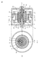
図1、2に示すように、ケーシング1の内面には、電動モータの固定子2がはめ込まれて固定されている。ケーシング1は、締結ボルトなどで蓋4が取り付けられている。電動モータの回転子3は、駆動シリンダ8の外周に固定されているので、駆動シリンダ8は、シャフト12回りに、電動モータの回転子3によって回転させられるようになっている。駆動シリンダ8は、円筒状のシリンダの両側に、サイドプレート27、27が、締結ボルト41などで取り付けられていて、円筒状のシリンダとサイドプレートとをあわせて駆動シリンダ8を構成する。シャフト12は、図1の右端でケーシング1に圧入されている。シャフト12の左端部は蓋4に挿入や圧入されており、シャフト12は回転しないようになっている。
(First embodiment)
As shown in FIGS. 1 and 2, the stator 2 of the electric motor is fitted and fixed to the inner surface of the casing 1. The lid 1 is attached to the casing 1 with fastening bolts or the like. Since the
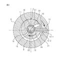
この静止したシャフト12に対して、モータの回転子3と駆動シリンダ8は一体化されて、ベアリング42を介して、回転可能になっている。図2に示すように、圧縮機としてのロータ11は、駆動プレート13によって、駆動シリンダ8に連れ回りするようになっている。ここで、電動モータの回転子3の回転中心O2に対して、シャフト12の軸心O1は偏心している。これら回転中心O2と軸心O1は、不動点である。ロータ11は、シャフト12に回転可能に嵌装されている。ロータ11は、不動の軸心O1回りに、回転可能で、駆動プレート13によって、駆動シリンダ8に連れ回りする。なお、本実施形態の駆動モータとしては、電動モータを使用しているが、ベルト伝動の場合に適用することも可能である。
The
駆動プレート13の一端は、駆動シリンダ8に揺動自在となるように設置され、駆動プレート13の他端は、ロータ11の摺動溝24に挿入されており、駆動シリンダ8の回転を駆動プレート13によりロータ11に伝達し、ロータ11が回転を行う。駆動シリンダ8とロータ11は、回転中常に仕切り点(接点)Cで接している。なお、駆動プレート13の一端は、ロータ11に揺動自在となるように設置され、駆動プレート13の他端は、駆動シリンダ8の摺動溝24に挿入されていても良い。
One end of the
圧縮すべき冷媒ガスなどの圧縮媒体は、図1、2に示すように、吸入口16から導入され、吸入通路17を経て、シャフト開口18、ロータ通路20から、吸入側の作動室(吸入室)10に導入される。シャフト開口18とロータ通路20は、常に全角度で連通している。シャフト開口18の出口には、シャフト12の一部の円周方向に、全周に亘って溝19が形成されている。
As shown in FIGS. 1 and 2, a compression medium such as a refrigerant gas to be compressed is introduced from the
駆動シリンダ8の一方側に固着されたサイドプレート27には、圧縮室吐出口21が設けられており、外側にはリードバルブ22(吐出弁部)が設置されている。リードバルブの代わりにその他のバルブ(ポペットバルブなど)であっても良い。もちろん、駆動シリンダ8の円筒状シリンダ外周に設けても良いが、遠心力の影響について配慮する必要がある。圧縮室吐出口27とリードバルブ22は、駆動シリンダ8の回転とともに、回転しながら圧縮ガスをケーシング内部の空間に吐出する。その後、ケーシング吐出口23から外部に吐出する。
The
次に、駆動プレート13について説明する。駆動プレート13は、従来技術のローリングピストンにおける、ベーンに相当する部材である。すなわち、本実施形態では、駆動プレート13は、圧縮室(圧縮側の作動室)9と吸入室10とを仕切る部材であり、かつ、ロータ11を駆動シリンダ8に連れ回りさせるための連結部材としての機能を有している。連結部材としての機能を果たすために、駆動プレート13の頭部13−1は、円筒面になっており、頭部13−1の中心軸に対して、駆動プレート13は、駆動シリンダ8に隙間13−2が設けられて、揺動することができるようになっている。ロータ11には、駆動シリンダ8の回転につれ、駆動プレート13が摺動溝24内を摺動する。これにより、連れまわり時に、駆動シリンダ8の回転中心O2と、ロータ11の軸心O1との偏心を吸収することができる。
Next, the
圧縮機構部は、ケーシング1に固定されたシャフト12の軸心O1周りに、回転自在なロータ11と、シャフト12とは偏心した回転中心O2で回転自在な駆動シリンダ8と、駆動シリンダ8とロータ11との間を連結する駆動プレート13とから構成される。ロータ11と駆動シリンダ8間の空間が、作動室となっている。この作動室は、駆動プレート13により2分され、圧縮室9と吸入室10とを形成する。駆動シリンダ8を回転駆動する電動モータ2、3により、駆動シリンダ8を回転させて、駆動シリンダ8とロータ11間に形成された作動室のうち、駆動プレート13の回転方向前方の圧縮室9で、吸入ガスを圧縮する。駆動シリンダ8とロータ11間に形成された作動室は、駆動プレート13と、駆動シリンダ8とロータ11の接点である仕切り点Cで、仕切られている。駆動プレート13の回転方向前方には、圧縮室9が形成され、後方には吸入室10が形成される。
The compression mechanism includes a
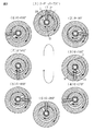
次に、上述の圧縮工程と吸引工程について、駆動シリンダの回転角θ(駆動プレート13の位置)が90°毎に、図3を参照して説明する。ここでは、分かりやすくするために、720°にして説明する。図3の(1)θ=0°から再度(1)θ=720°に至る順に説明する。(1)θ=0°では、吸入が完了した状態である。駆動プレート13と仕切り点Cとが一致するので、吸入室10と圧縮室9が合体する。θ=0°から駆動シリンダ8の回転角θが増大するにつれ、(2)〜(4)に見られるように、駆動プレート13の回転方向前方側と仕切り点Cとの間が閉鎖されて、圧縮室9での圧縮が進行する。
Next, the above-described compression process and suction process will be described with reference to FIG. 3 for each rotation angle θ of the drive cylinder (position of the drive plate 13) of 90 °. Here, in order to make it easy to understand, 720 ° will be described. Description will be made in the order from (1) θ = 0 ° to (1) θ = 720 ° in FIG. (1) At θ = 0 °, the inhalation is completed. Since the
(5)θ=360°で圧縮室9は消滅して、今度は、吸入室10が、駆動プレート13の回転方向後方と、仕切り点Cとの間に形成されて、(5)→(1)に至るまで吸入が進行して、圧縮工程と吸引工程が繰り返されて行く。以上720°にして説明したが、実際の圧縮工程と吸引工程は360°の1回転で同時に行われる。図3の(1)〜(5)において、駆動プレート13の回転方向前方側と、仕切り点Cとの間の圧縮室9で、圧縮が進行すると同時に、駆動プレート13の回転方向後方と、仕切り点Cとの間の吸入室10で、吸入が進行していることが分かる。(1)や(5)では、駆動プレート13と仕切り点Cとが一致するので、吸入室10と圧縮室9が合体する。
(5) When θ = 360 °, the
以上説明したように、駆動シリンダ8の回転により圧縮作動を行うため、駆動シリンダ8を、電動モータの回転子3内に配置しているので、圧縮機として小型にすることができる。シャフト12は回転しないので、シャフト12に吸入口16を設置して、ガスを吸入することができる。また、回転時に遠心力の影響を受けにくいサイドプレート27に、圧縮室吐出口27とリードバルブ22が設けられている。本実施形態では、ベーンノーズ摺動部を持たないため、従来技術のようなベーンノーズ摺動部の離脱や焼き付きがなく、低回転から高回転まで、性能と信頼性を両立確保することができ、電動モータ回転子に内蔵した、小型な圧縮機を提供することができるものである。さらに、従来技術では圧縮室を形成するためにロータを偏心運動させる必要があって、高速回転時は圧縮機の振動悪化を招いていたが、本実施形態ではロータ11は、不動の軸心O1において自転運動をするだけなので、圧縮機の振動悪化を防止できる。
As described above, since the compression operation is performed by the rotation of the
本実施形態では、駆動プレート13の頭部13−1は、円筒面になっており、頭部13−1の中心軸に対して、駆動プレート13は、揺動することができるようになっている。これに対して、図4に示すように、頭部のない平板の駆動プレート13にしても良い。この場合は、片側に円筒面を持つ2枚のシュー13−3が、駆動プレート13の端部を挟むように設置されている。その他は、図1、2と同じ構成となっている。ロータ11に形成された摺動溝24と駆動プレート13の先端が接する点においては、駆動プレート側の先端がR形状を有している。また、ロータ11に形成された摺動溝24の先端と駆動プレート13が接する点において、ロータ11側の先端がR形状を有している。
駆動プレート13の頭部13−1は、図1、2のように駆動シリンダ8に設けても、ロータ11に設置しても実施可能である。
In the present embodiment, the head 13-1 of the
The head 13-1 of the
1 ケーシング
8 駆動シリンダ
11 ロータ
12 シャフト
13 駆動プレート
1
Claims (5)
前記駆動シリンダ(8)内面と前記ロータ(11)外周が仕切り点(C)で接するように、前記シャフト(12)の軸心(O1)に対して前記駆動シリンダ(8)の回転中心(O2)を偏心させ、
前記仕切り点(C)と前記駆動プレート(13)で仕切られた、前記駆動シリンダ(8)内面と前記ロータ(11)外周との間の空間が、圧縮又は吸入を行う作動室(9、10)であり、
前記シャフト(12)と前記ロータ(11)に吸入通路(17、20)を設け吸入を行う作動室(10)内に吸入を行い、作動室(10)で圧縮した後前記サイドプレート(27)に吐出弁部を設けて吐出を行うようにした回転型圧縮機構。 Around the axis (O1) of the shaft (12) fixed to the casing (1), the rotor (11) is rotatable, and the drive cylinder is rotatable at the center of rotation (O2) where the shaft (12) is eccentric. (8) and the drive cylinder (8) or the rotor (11) is swingable with respect to the other, and is slidable with respect to the other. The drive cylinder (8) A rotary compression mechanism comprising: a drive plate (13) that rotationally connects the rotor (11); and a side plate (27) that constitutes a side surface of the drive cylinder (8),
The rotation center (O2) of the drive cylinder (8) with respect to the axis (O1) of the shaft (12) so that the inner surface of the drive cylinder (8) and the outer periphery of the rotor (11) are in contact with each other at a partition point (C). )
The space between the inner surface of the drive cylinder (8) and the outer periphery of the rotor (11), which is partitioned by the partition point (C) and the drive plate (13), compresses or sucks the working chamber (9, 10). ) And
A suction passage (17, 20) is provided in the shaft (12) and the rotor (11), the suction is performed in the working chamber (10) where the suction is performed, and the side plate (27) is compressed in the working chamber (10 ). A rotary compression mechanism in which a discharge valve portion is provided to perform discharge.
Priority Applications (5)
| Application Number | Priority Date | Filing Date | Title |
|---|---|---|---|
| JP2012142867A JP5901446B2 (en) | 2012-06-26 | 2012-06-26 | Rotary compressor |
| CN201380033782.2A CN104471250A (en) | 2012-06-26 | 2013-06-26 | Rotary compressor |
| PCT/JP2013/067528 WO2014003060A1 (en) | 2012-06-26 | 2013-06-26 | Rotary compressor |
| DE112013003254.6T DE112013003254T5 (en) | 2012-06-26 | 2013-06-26 | rotary compressor |
| US14/409,289 US20150176583A1 (en) | 2012-06-26 | 2013-06-26 | Rotary compressor |
Applications Claiming Priority (1)
| Application Number | Priority Date | Filing Date | Title |
|---|---|---|---|
| JP2012142867A JP5901446B2 (en) | 2012-06-26 | 2012-06-26 | Rotary compressor |
Publications (3)
| Publication Number | Publication Date |
|---|---|
| JP2014005795A JP2014005795A (en) | 2014-01-16 |
| JP2014005795A5 JP2014005795A5 (en) | 2014-09-18 |
| JP5901446B2 true JP5901446B2 (en) | 2016-04-13 |
Family
ID=49783201
Family Applications (1)
| Application Number | Title | Priority Date | Filing Date |
|---|---|---|---|
| JP2012142867A Expired - Fee Related JP5901446B2 (en) | 2012-06-26 | 2012-06-26 | Rotary compressor |
Country Status (5)
| Country | Link |
|---|---|
| US (1) | US20150176583A1 (en) |
| JP (1) | JP5901446B2 (en) |
| CN (1) | CN104471250A (en) |
| DE (1) | DE112013003254T5 (en) |
| WO (1) | WO2014003060A1 (en) |
Families Citing this family (12)
| Publication number | Priority date | Publication date | Assignee | Title |
|---|---|---|---|---|
| JP6108967B2 (en) * | 2013-06-06 | 2017-04-05 | 株式会社デンソー | Rotary compression mechanism |
| JP6271246B2 (en) | 2013-12-25 | 2018-01-31 | 株式会社Soken | Cylinder rotary compressor |
| JP6204867B2 (en) * | 2014-04-07 | 2017-09-27 | 株式会社Soken | Electric compressor |
| US9915319B2 (en) * | 2014-09-29 | 2018-03-13 | Delbert Tesar | Compact parallel eccentric rotary actuator |
| US10502284B2 (en) * | 2014-09-29 | 2019-12-10 | Delbert Tesar | Spring augmented orthotic or prosthetic equipped with a compact parallel eccentric actuator |
| JP6331938B2 (en) * | 2014-10-02 | 2018-05-30 | 株式会社Soken | Laminated core, synchronous motor, and electric compressor |
| JP2016108955A (en) * | 2014-12-02 | 2016-06-20 | 株式会社デンソー | Cylinder rotation type compressor |
| JP6349248B2 (en) | 2014-12-23 | 2018-06-27 | 株式会社Soken | Cylinder rotary compressor |
| JP2016186235A (en) * | 2015-03-27 | 2016-10-27 | 株式会社日本自動車部品総合研究所 | Cylinder rotation type compressor |
| JP6302428B2 (en) * | 2015-05-26 | 2018-03-28 | 株式会社Soken | Cylinder rotary compressor |
| JP6836831B2 (en) | 2015-11-12 | 2021-03-03 | 株式会社デンソー | Electric compressor |
| KR101982437B1 (en) * | 2018-02-07 | 2019-05-27 | 조성엽 | A hollowness pump |
Family Cites Families (9)
| Publication number | Priority date | Publication date | Assignee | Title |
|---|---|---|---|---|
| US2440593A (en) * | 1946-10-23 | 1948-04-27 | Harry B Miller | Radial vane pump mechanism |
| US4568257A (en) * | 1984-04-13 | 1986-02-04 | Moore Jesse C | Rotary pump |
| JPH029982A (en) * | 1988-06-27 | 1990-01-12 | Matsushita Electric Ind Co Ltd | Rotary compressor |
| JPH0261384A (en) * | 1988-08-25 | 1990-03-01 | Yoshio Takeuchi | Swingable vane type rotary compressor |
| JPH05215087A (en) * | 1992-02-05 | 1993-08-24 | Shingo Saida | Rotary compressor |
| CN1264792A (en) * | 2000-03-17 | 2000-08-30 | 李辛沫 | Blade-type rotary compressor |
| CA2532045C (en) * | 2005-01-18 | 2009-09-01 | Tecumseh Products Company | Rotary compressor having a discharge valve |
| EP2251545B1 (en) * | 2008-01-29 | 2017-04-12 | Dafeng Fengtai Fluid Machinery Technology Co., Ltd. | A rotary compressor |
| JP4962585B2 (en) * | 2010-03-19 | 2012-06-27 | ダイキン工業株式会社 | Rotary compressor |
-
2012
- 2012-06-26 JP JP2012142867A patent/JP5901446B2/en not_active Expired - Fee Related
-
2013
- 2013-06-26 WO PCT/JP2013/067528 patent/WO2014003060A1/en active Application Filing
- 2013-06-26 DE DE112013003254.6T patent/DE112013003254T5/en not_active Withdrawn
- 2013-06-26 CN CN201380033782.2A patent/CN104471250A/en active Pending
- 2013-06-26 US US14/409,289 patent/US20150176583A1/en not_active Abandoned
Also Published As
| Publication number | Publication date |
|---|---|
| CN104471250A (en) | 2015-03-25 |
| JP2014005795A (en) | 2014-01-16 |
| WO2014003060A1 (en) | 2014-01-03 |
| US20150176583A1 (en) | 2015-06-25 |
| DE112013003254T5 (en) | 2015-04-02 |
Similar Documents
| Publication | Publication Date | Title |
|---|---|---|
| JP5901446B2 (en) | Rotary compressor | |
| JP5828863B2 (en) | Gas compressor | |
| JP6187266B2 (en) | Electric compressor | |
| US20150198161A1 (en) | Scroll type compressor | |
| US20110002797A1 (en) | Rotary machine | |
| CN110121596B (en) | Double-rotation scroll compressor | |
| US20080193301A1 (en) | Composite fluid machine | |
| WO2013183436A1 (en) | Gas compressor | |
| KR101810903B1 (en) | Rotary compression mechanism | |
| KR101459183B1 (en) | Vane rotary compressor | |
| US20120224986A1 (en) | Rotary vane compressor | |
| WO2016129242A1 (en) | Compressor | |
| JP2008128069A (en) | Hermetic two stage rotary compressor | |
| CN109729720B (en) | Double-rotation scroll compressor | |
| KR20190095020A (en) | Motor-operated compressor | |
| EP2685106B1 (en) | Two-stage compressor and two-stage compression system | |
| CN110300853B (en) | Double-rotation scroll compressor | |
| JP5843729B2 (en) | Gas compressor | |
| WO2015152833A1 (en) | A revolving vane compressor and method of operating the same | |
| KR101020752B1 (en) | Air Compressor | |
| KR101954533B1 (en) | Rotary compressor | |
| KR20220079704A (en) | The rotary air compressor | |
| KR20230066964A (en) | Vane rotary compressor | |
| JP2014005775A (en) | Compressor | |
| JP5826708B2 (en) | Gas compressor |
Legal Events
| Date | Code | Title | Description |
|---|---|---|---|
| A521 | Request for written amendment filed |
Free format text: JAPANESE INTERMEDIATE CODE: A523 Effective date: 20140801 |
|
| A621 | Written request for application examination |
Free format text: JAPANESE INTERMEDIATE CODE: A621 Effective date: 20140919 |
|
| A131 | Notification of reasons for refusal |
Free format text: JAPANESE INTERMEDIATE CODE: A131 Effective date: 20150707 |
|
| A521 | Request for written amendment filed |
Free format text: JAPANESE INTERMEDIATE CODE: A523 Effective date: 20150901 |
|
| TRDD | Decision of grant or rejection written | ||
| A01 | Written decision to grant a patent or to grant a registration (utility model) |
Free format text: JAPANESE INTERMEDIATE CODE: A01 Effective date: 20160209 |
|
| A61 | First payment of annual fees (during grant procedure) |
Free format text: JAPANESE INTERMEDIATE CODE: A61 Effective date: 20160308 |
|
| R150 | Certificate of patent or registration of utility model |
Ref document number: 5901446 Country of ref document: JP Free format text: JAPANESE INTERMEDIATE CODE: R150 |
|
| LAPS | Cancellation because of no payment of annual fees |