JP5900129B2 - Blood pressure estimation parameter calibration method, blood pressure measurement method, and blood pressure measurement device - Google Patents
Blood pressure estimation parameter calibration method, blood pressure measurement method, and blood pressure measurement device Download PDFInfo
- Publication number
- JP5900129B2 JP5900129B2 JP2012094520A JP2012094520A JP5900129B2 JP 5900129 B2 JP5900129 B2 JP 5900129B2 JP 2012094520 A JP2012094520 A JP 2012094520A JP 2012094520 A JP2012094520 A JP 2012094520A JP 5900129 B2 JP5900129 B2 JP 5900129B2
- Authority
- JP
- Japan
- Prior art keywords
- blood pressure
- measurement
- blood vessel
- index value
- blood
- Prior art date
- Legal status (The legal status is an assumption and is not a legal conclusion. Google has not performed a legal analysis and makes no representation as to the accuracy of the status listed.)
- Expired - Fee Related
Links
Images


Description
本発明は、血圧推定処理に係るパラメーターを校正する方法等に関する。 The present invention relates to a method for calibrating parameters related to blood pressure estimation processing and the like.
従来より、超音波等を用いて血流や血管径、血圧を計測する装置や、血管の弾性率を計測する装置が考案されている。これらの装置は、被検者に痛みや不快感を与えることなく計測ができることを特徴としている。 2. Description of the Related Art Conventionally, devices that measure blood flow, blood vessel diameter, and blood pressure using ultrasonic waves, and devices that measure the elasticity of blood vessels have been devised. These devices are characterized in that measurement can be performed without causing pain or discomfort to the subject.
例えば、特許文献1には、血管径変化又は血管断面積変化と血圧変化とを非線形関係と捉え、血管の硬さを表すスティフネスパラメーターと血管径又は血管断面積とから、血圧を推定する手法が開示されている。
For example,
上記の血管径や血管断面積、血圧といった生体情報は、天候や気温の変化といった外因や、被検者の体調やストレスの度合といった内因によって時々刻々と変化する。そのため、上記の相関特性も時々刻々と変化する。従って、固定・画一的な相関特性に基づいて血圧を推定した場合、その推定結果は必ずしも信頼できる結果になるとは限らず、大きな誤差を含み得る場合があった。 The biological information such as the blood vessel diameter, the blood vessel cross-sectional area, and the blood pressure changes from time to time due to external factors such as changes in weather and temperature, and internal factors such as the physical condition of the subject and the degree of stress. For this reason, the above-mentioned correlation characteristic also changes every moment. Therefore, when the blood pressure is estimated based on the fixed and uniform correlation characteristics, the estimation result is not always reliable and may include a large error.
本発明は上述した課題に鑑みて為されたものであり、血圧を正しく推定するための新しい手法を提案することを目的とする。 The present invention has been made in view of the above-described problems, and an object thereof is to propose a new method for correctly estimating blood pressure.
以上の課題を解決するための第1の形態は、対象動脈が走行している被検者の第1部位において当該対象動脈の血管径又は血管断面積(以下包括して「血管断面指標値」と称す。)を計測する血管断面指標値計測と、前記第1部位とは異なる第2部位において前記被検者の血圧を計測する血圧計測とを、前記第2部位が前記対象動脈が走行している部位であるか否かに応じて同時或いは時分割に行うことと、前記血管断面指標値計測による計測結果と前記血圧計測による計測結果とを用いて、血管断面指標値から血圧を推定する血圧推定処理に係るパラメーターを校正することと、を含む血圧推定パラメーター校正方法である。 The first form for solving the above-described problem is that the blood vessel diameter or blood vessel cross-sectional area of the target artery (hereinafter collectively referred to as “blood vessel cross-section index value”) in the first part of the subject where the target artery is running. Blood vessel cross-sectional index value measurement for measuring) and blood pressure measurement for measuring the blood pressure of the subject at a second site different from the first site, the target artery running on the second site. The blood pressure is estimated from the blood vessel cross-sectional index value using the measurement result by the blood vessel cross-section index value measurement and the measurement result by the blood pressure measurement, depending on whether or not the region is a part of the blood vessel. And calibrating parameters relating to blood pressure estimation processing.
また、他の形態として、対象動脈が走行している被検者の第1部位において当該対象動脈の血管断面指標値を計測する血管断面指標値計測部と、前記第1部位とは異なる第2部位において前記被検者の血圧を外部の血圧計測装置で計測する血圧計測の実行を促す血圧計測誘導報知と、前記血管断面指標値計測部による計測実行とを制御する制御部であって、前記第2部位が前記対象動脈が走行している部位であるか否かに応じて、前記血圧計測装置による計測と前記血管断面指標値計測部による計測とを、同時或いは時分割に行うように制御する制御部と、前記血管断面指標値計測部による計測結果と前記血圧計測装置による計測結果とを用いて、血管断面指標値から血圧を推定する血圧推定処理に係るパラメーターを校正する校正部と、を備えた血圧計測装置を構成することとしてもよい。 As another form, a blood vessel cross-section index value measurement unit that measures a blood vessel cross-section index value of the target artery at the first site of the subject where the target artery is running, and a second that is different from the first site. A control unit for controlling blood pressure measurement guidance notification for urging execution of blood pressure measurement for measuring the blood pressure of the subject in an external blood pressure measurement device at a site, and measurement execution by the blood vessel cross-section index value measurement unit, Control is performed so that the measurement by the blood pressure measurement device and the measurement by the blood vessel cross-section index value measurement unit are performed simultaneously or in time division depending on whether or not the second part is a part where the target artery is running. A calibration unit that calibrates a parameter related to blood pressure estimation processing for estimating blood pressure from a blood vessel cross-section index value, using a control unit that performs measurement by the blood vessel cross-section index value measurement unit and a measurement result by the blood pressure measurement device; The It is also possible to configure the example was a blood pressure measuring device.
この第1の形態等によれば、対象動脈が走行している被検者の第1部位において当該対象動脈の血管断面指標値を計測する血管断面指標値計測と、第1部位とは異なる第2部位において被検者の血圧を計測する血圧計測とを、第2部位が対象動脈が走行している部位であるか否かに応じて同時或いは時分割に行う。例えば、加圧血圧計を用いた血圧計測では、血圧の計測時に第2部位が加圧されて駆血されるため、第1部位において対象動脈の血管断面指標値を正しく計測することが困難である。そのため、例えば、第2部位が対象動脈が走行している部位である場合には、血管断面指標値計測と血圧計測とを時分割に行うようにすると好適である。 According to the first aspect and the like, the blood vessel cross-sectional index value measurement for measuring the blood vessel cross-sectional index value of the target artery at the first site of the subject where the target artery is running differs from the first site. The blood pressure measurement for measuring the blood pressure of the subject at two sites is performed simultaneously or in time division depending on whether or not the second site is a site where the target artery is running. For example, in blood pressure measurement using a pressurized sphygmomanometer, it is difficult to correctly measure the blood vessel cross-sectional index value of the target artery in the first part because the second part is pressurized and driven during blood pressure measurement. is there. Therefore, for example, when the second part is a part where the target artery is running, it is preferable to perform blood vessel cross-sectional index value measurement and blood pressure measurement in a time-sharing manner.
また、第1の形態等では、血管断面指標値計測による計測結果と血圧計測による計測結果とを用いて、血管断面指標値から血圧を推定する血圧推定処理に係るパラメーターを校正する。血管断面指標値及び血圧を実際に計測した計測結果を用いて血圧推定処理に係るパラメーターが校正されるため、以降の血圧推定処理では被検者の血圧を正しく推定することが可能となる。 In the first embodiment and the like, a parameter related to blood pressure estimation processing for estimating blood pressure from a blood vessel cross-section index value is calibrated using a measurement result by blood vessel cross-section index value measurement and a measurement result by blood pressure measurement. Since the parameters related to the blood pressure estimation process are calibrated using the blood vessel cross-sectional index value and the measurement result obtained by actually measuring the blood pressure, the blood pressure of the subject can be correctly estimated in the subsequent blood pressure estimation process.
また、第2の形態として、第1の形態の血圧推定パラメーター校正方法において、前記対象動脈は橈骨動脈であり、前記第1部位は手首部であり、前記第2部位は上腕部であり、前記第1部位と前記第2部位とが同じ腕であるか否かに応じて前記血管断面指標値計測と前記血圧計測とを同時或いは時分割に行うことを特徴とする、血圧推定パラメーター校正方法を構成することとしてもよい。 Further, as a second form, in the blood pressure estimation parameter calibration method of the first form, the target artery is a radial artery, the first part is a wrist part, and the second part is an upper arm part, A blood pressure estimation parameter calibration method, wherein the blood vessel cross-section index value measurement and the blood pressure measurement are performed simultaneously or in a time-sharing manner depending on whether the first part and the second part are the same arm or not. It may be configured.
この第2の形態によれば、橈骨動脈が走行している被検者の手首部において当該橈骨動脈の血管断面指標値を計測する。また、上腕部において被検者の血圧を計測する。そして、手首部と上腕部とが同じ腕であるか否かに応じて血管断面指標値計測と血圧計測とを同時或いは時分割に行う。手首部と上腕部とが同じ腕(例えば右腕なら右腕。)である場合は、上腕部で血圧を計測する際に上腕部で駆血されるため、手首部での血管断面指標値計測と上腕部での血圧計測とを時分割に行うようにすると好適である。 According to the second embodiment, the blood vessel cross-sectional index value of the radial artery is measured at the wrist of the subject where the radial artery is running. In addition, the blood pressure of the subject is measured at the upper arm. Then, blood vessel cross-section index value measurement and blood pressure measurement are performed simultaneously or in a time-sharing manner depending on whether or not the wrist and upper arm are the same arm. When the wrist and upper arm are the same arm (for example, the right arm for the right arm), blood pressure is measured at the upper arm when blood pressure is measured at the upper arm, so blood vessel cross-sectional index value measurement at the wrist and the upper arm It is preferable to perform blood pressure measurement at the time division in a time division manner.
また、第3の形態として、第1又は第2の形態の血圧推定パラメーター校正方法において、前記血管断面指標値計測では、所定時間の間、前記対象動脈の血管断面指標値を計測し、前記血圧計測では、収縮期血圧及び拡張期血圧を計測し、前記パラメーターを校正することは、前記所定時間の間の前記血管断面指標値計測の計測結果から、収縮期血管断面指標値及び拡張期血管断面指標値を求めることと、前記収縮期血圧及び前記拡張期血圧と前記収縮期血管断面指標値及び前記拡張期血管断面指標値とに基づいて前記パラメーターを校正することと、を含む、血圧推定パラメーター校正方法を構成することとしてもよい。 Further, as a third form, in the blood pressure estimation parameter calibration method of the first or second form, in the blood vessel cross-section index value measurement, a blood vessel cross-section index value of the target artery is measured for a predetermined time, and the blood pressure In the measurement, the systolic blood pressure and the diastolic blood pressure are measured, and the parameters are calibrated from the measurement result of the blood vessel cross-sectional index value measurement during the predetermined time from the systolic blood vessel cross-sectional index value and the diastolic blood vessel cross-section. Obtaining an index value, and calibrating the parameter based on the systolic blood pressure and the diastolic blood pressure, the systolic blood vessel cross-sectional index value and the diastolic blood vessel cross-sectional index value, and a blood pressure estimation parameter A calibration method may be configured.
この第3の形態によれば、血管断面指標値計測では、所定時間の間、対象動脈の血管断面指標値を計測する。また、血圧計測では、収縮期血圧及び拡張期血圧を計測する。所定時間の間の血管断面指標値計測の計測結果から、収縮期血管断面指標値及び拡張期血管断面指標値を求める。そして、収縮期血圧及び拡張期血圧と収縮期血管断面指標値及び拡張期血管断面指標値とに基づいて、血圧推定処理に係るパラメーターを校正する。これにより、血圧推定処理に係るパラメーターの校正を適切に行うことが可能となる。 According to the third aspect, in the blood vessel cross-section index value measurement, the blood vessel cross-section index value of the target artery is measured for a predetermined time. In blood pressure measurement, systolic blood pressure and diastolic blood pressure are measured. A systolic blood vessel cross-sectional index value and a diastolic blood vessel cross-sectional index value are obtained from the measurement result of the blood vessel cross-sectional index value measurement during a predetermined time. Based on the systolic blood pressure and the diastolic blood pressure, the systolic blood vessel cross-sectional index value, and the diastolic blood vessel cross-sectional index value, the parameters relating to the blood pressure estimation process are calibrated. This makes it possible to appropriately calibrate parameters related to blood pressure estimation processing.
また、第4の形態として、第1〜第3の何れかの形態の血圧推定パラメーター校正方法を行った後に、前記第1部位において前記対象動脈の血管断面指標値を計測する通常計測を行うことと、前記血圧推定パラメーター校正方法により校正されたパラメーターを用いて、前記通常計測の計測結果から前記血圧推定処理を行って血圧を推定することと、を含む血圧計測方法を構成することとしてもよい。 In addition, as a fourth embodiment, after performing the blood pressure estimation parameter calibration method according to any one of the first to third embodiments, normal measurement is performed in which the blood vessel cross-sectional index value of the target artery is measured at the first site. And using the parameters calibrated by the blood pressure estimation parameter calibration method to estimate the blood pressure by performing the blood pressure estimation process from the measurement result of the normal measurement, the blood pressure measurement method may be configured. .
この第4の形態によれば、上記の何れかの形態の血圧推定パラメーター校正方法を行った後に、第1部位において対象動脈の血管断面指標値を計測する通常計測を行う。そして、血圧推定パラメーター校正方法により校正されたパラメーターを用いて、通常計測の計測結果から血圧推定処理を行って血圧を推定することで、被検者の血圧を正しく推定することが可能となる。 According to the fourth aspect, after performing the blood pressure estimation parameter calibration method according to any one of the above forms, normal measurement is performed in which the blood vessel cross-sectional index value of the target artery is measured at the first site. Then, by using the parameter calibrated by the blood pressure estimation parameter calibration method, blood pressure estimation processing is performed from the measurement result of the normal measurement to estimate the blood pressure, thereby correctly estimating the blood pressure of the subject.
本発明を適用した実施形態として、被検者の手首を対象部位とし、対象動脈を橈骨動脈として、被検者の血圧を計測する実施形態について説明する。本実施形態では、血管径を血管断面指標値として説明するが、血管径の代わりに血管断面積を用いてもよい(その場合、以下の文章中の「血管径」を「血管断面積」に置き換えて読めばよい。)。本発明を適用可能な形態が以下説明する実施形態に限定されるわけでないことは勿論である。 As an embodiment to which the present invention is applied, an embodiment will be described in which the subject's wrist is the target site and the subject artery is the radial artery, and the blood pressure of the subject is measured. In the present embodiment, the blood vessel diameter is described as the blood vessel cross-sectional index value, but the blood vessel cross-sectional area may be used instead of the blood vessel diameter (in this case, “blood vessel diameter” in the following text is changed to “blood vessel cross-sectional area”). Just replace it and read it.) Of course, the form to which the present invention can be applied is not limited to the embodiment described below.
1.概略構成
図1(1)は、本実施形態における超音波血圧計1の概略構成を示す図である。超音波血圧計1は、帯状部15を用いて本体部を被検者の対象部位(特には手首)に装着可能に構成されている。帯状部15は、被検者の対象部位に装置本体を装着するための装着具であり、面ファスナーを備えたバンドや、測定部位を挟持するためのクリップ等を有して構成される。超音波血圧計1は、被検者の右手首及び左手首の何れにも装着可能であるが、本実施形態では、被検者の左手首に装着する場合を例に挙げて説明する。
1. Schematic Configuration FIG. 1 (1) is a diagram showing a schematic configuration of an
超音波血圧計1の本体部は、ヒンジ部11を介して第1部位1Aと第2部位1Bとが接続されて構成されている。
The main body of the
第1部位1Aには、操作ボタン12と、液晶表示器13と、スピーカー14とが設けられている。
In the
操作ボタン12は、血圧の計測開始指示や、血圧の計測に係る各種諸量を被検者が操作入力するために用いられる。
The
液晶表示器13には、超音波血圧計1による血圧の計測結果が表示される。表示方法としては、血圧の計測値を数値で表示することとしてもよいし、グラフなどで表示することとしてもよい。
The
スピーカー14からは、血圧の計測に係る各種の音声ガイダンス等が音出力される。本実施形態では、超音波血圧計1の校正に当たって加圧血圧計2による血圧の計測が必要となる。そのため、例えば、加圧血圧計2の着脱を指示する音声ガイダンスをスピーカー14から音出力させるなどしてもよい。
From the
第2部位1Bには、超音波センサー部20が設けられている。超音波センサー部20は、超音波振動子をアレイ状に配列した超音波の送受信部である。超音波センサー部20は、送信部から数MHz〜数十MHzの超音波のパルス信号或いはバースト信号を、対象動脈に向けて送信する。そして、対象動脈の前壁及び後壁からの反射波を受信部で受信し、前壁及び後壁の反射波の受信時間差から、対象動脈の血管径を計測する。
An
なお、図示を省略しているが、超音波血圧計1の本体部には、機器を統合的に制御するための制御基板が内蔵されている。制御基板には、マイクロプロセッサーやメモリー、超音波の送受信に係る回路、内部バッテリー等が実装されている。
Although not shown, the main body of the
図1(2)は、被検者の左手首に超音波血圧計1を装着した状態を示す図である。図1(2)に示すように、超音波血圧計1は、超音波を送受信する計測面が手首の内側を向くような姿勢で被検者の手首に装着される。この際、超音波センサー部20が設けられた第2部位1Bが、被検者の手首の親指側にくるように装着される。これは、対象動脈を手首の親指側を流れる橈骨動脈とし、その直上に超音波センサー部20が位置するようにするためである。
FIG. 1 (2) is a diagram showing a state in which the
本実施形態では、超音波血圧計1とは別の外部の血圧計測装置を用いて、超音波血圧計1を校正する。血圧計測装置としては種々の血圧計を適用可能であるが、本実施形態では、オシロメトリック法を用いて収縮期血圧(最高血圧)及び拡張期血圧(最低血圧)を計測可能に構成された加圧血圧計2(カフ型血圧計)を用いる。
In the present embodiment, the
この加圧血圧計2として、本実施形態では、上腕部に装着するタイプの上腕装着型加圧血圧計2Aと、手首部に装着するタイプの手首装着型加圧血圧計2Bとの2種類の加圧血圧計2を想定する。この2種類の加圧血圧計2のどちらを用いるかは、被検者がどちらの加圧血圧計2を保有しているかによる。つまり、被検者は、自身が保有している加圧血圧計2を用いて、超音波血圧計1を校正することになる。
In this embodiment, as the
図2(1)は、上腕装着型加圧血圧計2Aの構成図である。上腕装着型加圧血圧計2Aは、例えば、血圧を感知するカフと装置本体とが別体として構成され、カフを被検者の上腕に巻き付け、上腕動脈の血圧を計測する。上腕装着型加圧血圧計2Aは、被検者の右上腕部及び左上腕部の何れかに装着可能である。
FIG. 2 (1) is a block diagram of the upper arm-mounted
図2(2)は、手首装着型加圧血圧計2Bの構成図である。手首装着型加圧血圧計2Bは、血圧を感知するカフと装置本体とが一体的に構成され、カフを被検者の手首に巻き付け、手首動脈の血圧を計測する。本実施形態では超音波血圧計1を左手首に装着するため、手首装着型加圧血圧計2Bを用いる場合は、被検者の右手首に装着することとなる。
FIG. 2 (2) is a configuration diagram of the wrist-worn
加圧血圧計2を装着した状態で、被検者の第1部位において対象動脈の血管径を計測する血管径計測と、第1部位とは異なる第2部位において被検者の血圧を計測する血圧計測とを、第2部位が対象動脈が走行している部位であるか否かに応じて、同時或いは時分割に行う。そして、血管径計測による計測結果と血圧計測による計測結果とを用いて、血管径から血圧を推定する血圧推定処理に係るパラメーターの値を校正する。
With the
本実施形態では、被検者の左手首部を第1部位とし、左腕の橈骨動脈を対象動脈として血管径計測を行う。この場合、対象動脈が走行している部位は左上腕部であり、対象動脈が走行していない部位は右上腕部及び右手首部となる。左上腕部を第2部位とし、上腕装着型加圧血圧計2Aを用いて校正を行う場合は、カフによる加圧により左上腕部で駆血されるため、同時に左手首部で橈骨動脈の血管径を正しく計測することができなくなる。そこで、この場合には、血管径計測と血圧計測とを時分割で行う。
In this embodiment, blood vessel diameter measurement is performed with the left wrist of the subject as the first site and the radial artery of the left arm as the target artery. In this case, the part where the target artery is running is the left upper arm part, and the part where the target artery is not running is the upper right arm part and the right wrist part. When the left upper arm is the second part and calibration is performed using the upper arm-mounted
一方、右上腕部を第2部位として上腕装着型加圧血圧計2Aを用いて校正を行う場合と、右手首部を第2部位として手首装着型加圧血圧計2Bを用いて校正を行う場合とでは、上記のような問題は生じない。つまり、カフによる加圧により右上腕部や右手首部が駆血されたとしても、左手首部を走行する橈骨動脈には影響しないため、血管径計測と血圧計測とを同時に行うことができる。
On the other hand, in the case where calibration is performed using the upper arm wearing
また、本実施形態では、血管径から血圧を推定する血圧推定処理に係るパラメーターを校正する。血管径から血圧を推定するためには、血管径と血圧とを結びつける相関特性を利用することができる。血管径と血圧とは、例えばある非線形な相関特性で結びつけることが可能である。 In the present embodiment, a parameter related to blood pressure estimation processing for estimating blood pressure from a blood vessel diameter is calibrated. In order to estimate the blood pressure from the blood vessel diameter, a correlation characteristic that links the blood vessel diameter and the blood pressure can be used. For example, the blood vessel diameter and the blood pressure can be linked with a certain nonlinear correlation characteristic.
具体的には、血管に掛かる圧力と、各血圧時における血管径とを用いて、例えば次式(1)のような相関式で相関特性を表すことができる。
P=Pd・exp[β(D/Dd−1)]・・・(1)
但し、β=ln(Ps/Pd)/(Ds/Dd−1)
Specifically, using the pressure applied to the blood vessel and the blood vessel diameter at each blood pressure, for example, the correlation characteristic can be expressed by a correlation equation such as the following equation (1).
P = Pd · exp [β (D / Dd−1)] (1)
Where β = ln (Ps / Pd) / (Ds / Dd−1)
ここで、「Ps」は収縮期血圧であり、「Pd」は拡張期血圧である。また、「Ds」は収縮期血圧のときの血管径である収縮期血管径であり、「Dd」は拡張期血圧のときの血管径である拡張期血管径である。また、「β」はスティフネスパラメーターと呼ばれる血管弾性指標値である。 Here, “Ps” is systolic blood pressure, and “Pd” is diastolic blood pressure. “Ds” is a systolic blood vessel diameter that is a blood vessel diameter at the time of systolic blood pressure, and “Dd” is a diastolic blood vessel diameter that is a blood vessel diameter at the time of diastolic blood pressure. “Β” is a vascular elasticity index value called a stiffness parameter.
本実施形態では、被検者の第1部位(例えば左手首部)での血管径計測による計測結果と、被検者の第2部位(例えば左上腕部)での血圧計測による計測結果とを用いて、上記のスティフネスパラメーター「β」を校正する。このスティフネスパラメーター「β」は、血管断面指標値から血圧を推定する血圧推定処理に係るパラメーターの一種である。 In this embodiment, the measurement result by blood vessel diameter measurement at the first part (for example, the left wrist part) of the subject and the measurement result by blood pressure measurement at the second part (for example, the left upper arm part) of the subject are used. Then, the stiffness parameter “β” is calibrated. This stiffness parameter “β” is a type of parameter related to blood pressure estimation processing for estimating blood pressure from a blood vessel cross-sectional index value.
スティフネスパラメーター「β」を校正することができれば、このスティフネスパラメーター「β」と、校正時に求めた拡張期血圧「Pd」及び拡張期血管径「Dd」とを用いることで、血管径「D」と血圧「P」とを結び付ける式(1)の相関式を定めることができる。以降の血圧推定処理では、超音波を用いて計測した血管径「D」を相関式に代入することで、血圧「P」を推定することができる。 If the stiffness parameter “β” can be calibrated, by using this stiffness parameter “β”, the diastolic blood pressure “Pd” and the diastolic blood vessel diameter “Dd” obtained at the time of calibration, the blood vessel diameter “D” and The correlation formula of Formula (1) that links the blood pressure “P” can be determined. In the subsequent blood pressure estimation process, the blood pressure “P” can be estimated by substituting the blood vessel diameter “D” measured using ultrasonic waves into the correlation equation.
2.機能構成
図3は、超音波血圧計1の機能構成の一例を示すブロック図である。超音波血圧計1は、上記の血圧推定パラメーター校正方法を用いて血圧推定処理に係るパラメーターを校正するとともに、校正したパラメーターを用いて血圧推定処理を行って血圧を推定する血圧計測装置である。
2. Functional Configuration FIG. 3 is a block diagram illustrating an example of a functional configuration of the
超音波血圧計1は、超音波センサー部20と、第1入力部40と、第2入力部60と、処理部100と、操作部200と、表示部300と、音出力部400と、通信部500と、時計部600と、記憶部800とを有して構成される。
The
超音波センサー部20は、超音波の送受信部であり、超音波の送受信回路を有して構成される。送受信回路は、例えば、送受信制御部120から出力される送受信制御信号に従って、超音波の送信モードと受信モードとを時分割方式で切り替えて超音波を送受信する。
The
送受信回路は、送信用の構成として、所定周波数のパルス信号を生成する超音波発振回路や、生成されたパルス信号を遅延させる送信遅延回路等を有して構成される。また、受信用の構成として、受信信号を遅延させる受信遅延回路や、受信信号から所定の周波数成分を抽出するフィルター、受信信号を増幅する増幅器等を有して構成される。 The transmission / reception circuit includes an ultrasonic oscillation circuit that generates a pulse signal of a predetermined frequency, a transmission delay circuit that delays the generated pulse signal, and the like as a configuration for transmission. The reception configuration includes a reception delay circuit that delays the reception signal, a filter that extracts a predetermined frequency component from the reception signal, an amplifier that amplifies the reception signal, and the like.
第1入力部40は、上腕装着型加圧血圧計2Aと接続して、当該上腕装着型加圧血圧計2Aによって計測された血圧の計測値を入力する入力部である。
The
第2入力部60は、手首装着型加圧血圧計2Bと接続して、当該手首装着型加圧血圧計2Bによって計測された血圧の計測値を入力する入力部である。
The
処理部100は、超音波血圧計1の各部を統括的に制御する制御装置及び演算装置であり、CPU(Central Processing Unit)やDSP(Digital Signal Processor)等のマイクロプロセッサーや、ASIC(Application Specific Integrated Circuit)等を有して構成される。
The
処理部100は、主要な機能部として、送受信制御部120と、血管径算出部130と、制御部140と、校正部150と、血圧推定部160とを有する。但し、これらの機能部は一実施例として記載したものに過ぎず、必ずしもこれら全ての機能部を必須構成要素としなければならないわけではない。また、これら以外の機能部を必須構成要素としてもよいことは勿論である。
The
送受信制御部120は、超音波センサー部20による超音波の送受信を制御する。具体的には、超音波センサー部20に対して送受信制御信号を出力し、上記の送信モードと受信モードとを切り替える制御を行う。
The transmission /
血管径算出部130は、超音波センサー部20から入力した信号処理結果に基づいて、対象動脈の血管径を算出する。具体的には、対象動脈の前壁及び後壁からの超音波の反射波の受信時間差を検出することで、対象動脈の血管径を算出する。血管径算出部130は、拡張期血管径を算出する拡張期血管径算出部131と、収縮期血管径を算出する収縮期血管径算出部133とを機能部として有する。
The blood vessel
超音波センサー部20と、送受信制御部120と、血管径算出部130とによって、対象部位における対象動脈の血管径を計測する血管径計測部110が構成される。血管径計測部110は、対象動脈が走行している被検者の第1部位において当該対象動脈の血管断面指標値を計測する血管断面指標値計測部の一種である。血管径計測部110は、血管径を連続的に計測可能に構成されている。血管径を連続的に計測する手法としては、例えば、位相差トラッキング法を適用することができる。なお、位相差トラッキング法それ自体は従来公知であるため、詳細については説明を省略する。
The
制御部140は、第1部位とは異なる第2部位において被検者の血圧を加圧血圧計2で計測する血圧計測の実行を促す血圧計測誘導報知と、血管径計測部110による計測実行とを制御する制御部である。また、制御部140は、第2部位が対象動脈が走行している部位であるか否かに応じて、加圧血圧計2による計測と血管径計測部110による計測とを、同時或いは時分割に行うように制御する。
The
校正部150は、血圧計測装置による計測結果と血管径計測部110による計測結果とを用いて、血管径から血圧を推定する血圧推定処理に係るパラメーターである相関式パラメーターを校正する。
The
血圧推定部160は、血管径計測部110によって計測された血管径と、校正部150によって構成された相関式パラメーターに基づき定められる相関式とを用いて、被検者の血圧を推定する血圧推定処理を行う。血圧推定部160は、拡張期血圧を推定する拡張期血圧推定部161と、収縮期血圧を推定する収縮期血圧推定部163とを機能部として有する。
The blood
操作部200は、ボタンスイッチ等を有して構成される入力装置であり、押下されたボタンの信号を処理部100に出力する。この操作部200の操作により、血管径の計測開始指示等の各種指示入力がなされる。操作部200は、図1の操作ボタン12に相当する。
The
表示部300は、LCD(Liquid Crystal Display)等を有して構成され、処理部100から入力される表示信号に基づく各種表示を行う表示装置である。表示部300には、血圧推定部160による血圧の推定結果等が表示される。表示部300は、図1の液晶表示器13に相当する。
The
音出力部400は、処理部100から入力される音出力信号に基づく各種音出力を行う音出力装置である。音出力部400は、図1のスピーカー14に相当する。
The
通信部500は、処理部100の制御に従って、装置内部で利用される情報を外部の情報処理装置との間で送受するための通信装置である。通信部500の通信方式としては、所定の通信規格に準拠したケーブルを介して有線接続する形式や、クレイドルと呼ばれる充電器と兼用の中間装置を介して接続する形式、近距離無線通信を利用して無線接続する形式等、種々の方式を適用可能である。上腕装着型加圧血圧計2Aや手首装着型加圧血圧計2Bとの接続が通信接続となる場合には、第1入力部40及び第2入力部60が通信部500となる。
The
時計部600は、水晶振動子及び発振回路でなる水晶発振器等を有して構成され、時刻を計時する計時装置である。時計部600の計時時刻は、処理部100に随時出力される。
The
記憶部800は、ROM(Read Only Memory)やフラッシュROM、RAM(Random Access Memory)等の記憶装置を有して構成される。記憶部800は、超音波血圧計1のシステムプログラムや、送受信制御機能、血管径計測機能、血圧推定機能といった各種機能を実現するための各種プログラム、データ等を記憶している。また、各種処理の処理中データ、処理結果などを一時的に記憶するワークエリアを有する。
The
記憶部800には、プログラムとして、例えば、処理部100によって読み出され、メイン処理(図4参照)として実行されるメインプログラム810が記憶されている。メインプログラム810は、校正用データ取得処理(図5参照)として実行される校正用データ取得プログラム811をサブルーチンとして含む。これらの処理については、フローチャートを用いて詳細に後述する。
The
また、記憶部800には、データとして、装着部位設定データ820と、校正用データ830と、相関式パラメーターデータ840と、血管径ロギングデータ850と、血圧推定結果データ860とが記憶される。
In addition, the
装着部位設定データ820は、被検者が超音波血圧計1や上腕装着型加圧血圧計2A、手首装着型加圧血圧計2Bを装着する部位に係る設定データである。この装着部位設定データ820は、例えば初期設定として、操作部200を介して被検者によって操作入力される。
The wearing
校正用データ830は、相関式パラメーターの校正を行うために用いられるデータであり、血圧計測データ831と、血管径計測データ833と、特性値データ835とがこれに含まれる。
The
血圧計測データ831は、校正用データ取得処理において、加圧血圧計2の血圧計測による計測結果のデータであり、拡張期血圧及び収縮期血圧の計測結果がこれに含まれる。
The blood
血管径計測データ833は、校正用データ取得処理において、超音波センサー部20の検出結果に基づいて血管径算出部130により算出された血管径の算出結果のデータであり、拡張期血管径と収縮期血管径とがこれに含まれる。
The blood vessel
特性値データ835は、血圧計測データ831に記憶された血圧の計測結果と、血管径計測データ833に記憶された血管径の計測結果とを対応付けた特性値が記憶されたデータである。特性値には、拡張期血圧と拡張期血管径とを対応付けた拡張期特性値と、収縮期血圧と収縮期血管径とを対応付けた収縮期特性値とが含まれる。これらの特性値は、相関式パラメーターを校正するために用いられる。
The
相関式パラメーターデータ840は、血管径と血圧の相関特性を表す相関式のパラメーター値が記憶されたデータである。例えば、式(1)におけるスティフネスパラメーター「β」がこれに含まれる。
The correlation
血管径ロギングデータ850は、血管径計測部110によって計測された血管径のロギングデータである。例えば、所定の時間間隔毎のタイミングで血管径計測部110によって計測された血管径が、計測時刻と対応付けて時系列に記憶される。
The blood vessel
血圧推定結果データ860は、血圧推定部160が血圧推定処理を行うことで推定した血圧の推定結果が記憶されたデータである。
The blood pressure
3.処理の流れ
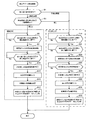
図4は、処理部100が、記憶部800に記憶されているメインプログラム810に従って実行するメイン処理の流れを示すフローチャートである。
3. Processing Flow FIG. 4 is a flowchart showing a flow of main processing executed by the
最初に、処理部100は、初期設定を行う(ステップA1)。具体的には、操作部200を介して被検者によって入力される装着部位に基づいて、超音波血圧計1の装着腕、使用する加圧血圧計2の種別及び当該加圧血圧計2の装着腕を設定し、装着部位設定データ820として記憶部800に記憶させる。
First, the
次いで、処理部100は、校正用データの取得タイミングであるか否かを判定する(ステップA3)。この校正用データの取得タイミングは、例えば、1日2回のある決められた時刻(例えば朝8時と夕方6時)を設定しておくことができる。
Next, the
校正用データの取得タイミングであると判定した場合は(ステップA3;Yes)、制御部140が、第1部位とは異なる第2部位において被検者の血圧を外部の血圧計測装置(加圧血圧計2)で計測する血圧計測の実行を促す血圧計測誘導報知を行う(ステップA5)。そして、処理部100は、記憶部800に記憶されている校正用データ取得プログラム811に従って、校正用データ取得処理を行う(ステップA7)。
When it is determined that it is the timing for acquiring the calibration data (step A3; Yes), the
図5は、校正用データ取得処理の流れを示すフローチャートである。
最初に、処理部100は、加圧血圧計2の種別を判定し(ステップB1)、種別が上腕装着型加圧血圧計2Aであると判定した場合は(ステップB1;上腕装着型)、超音波血圧計1と上腕装着型加圧血圧計2Aの装着腕を判定する(ステップB3)。装着腕が異なると判定した場合(ステップB3;異なる)、処理部100は、同時方式による校正用データの取得処理を行う(ステップB5〜B17)。
FIG. 5 is a flowchart showing the flow of calibration data acquisition processing.
First, the
この同時方式による処理では、処理部100は、操作部200の加圧血圧計2による血圧計測の開始確認ボタンが押下されたか否かを判定する(ステップB5)。処理部100は、開始確認ボタンが押下されるまで待機し(ステップB5;No)、開始確認ボタンが押下されたことを検出すると(ステップB5;Yes)、超音波による血管径の計測を開始し、その計測結果を血管径計測データ833として校正用データ830に記憶させる(ステップB7)。
In the processing by this simultaneous method, the
次いで、処理部100は、操作部200の加圧血圧計2による血圧計測の終了確認ボタンが押下されたか否かを判定する(ステップB9)。処理部100は、終了確認ボタンが押下されるまで待機し(ステップB9;No)、終了確認ボタンが押下されたことを検出すると(ステップB9;Yes)、超音波による血管径の計測を終了する(ステップB11)。
Next, the
上腕装着型加圧血圧計2Aによって血圧の計測を行うには、数十秒程度の時間を要する。ステップB5〜B11の一連の処理では、上腕装着型加圧血圧計2Aによる血圧の計測を開始してから血圧の計測が終了するまでの間、血管径計測部110が血管径を連続的に計測する。
It takes about several tens of seconds to measure blood pressure with the upper arm-mounted
ステップB11の後、処理部100は、第1入力部40を介して上腕装着型加圧血圧計2Aから血圧の計測値を入力し、血圧計測データ831として校正用データ830に記憶させる(ステップB13)。
After step B11, the
次いで、処理部100は、血管径の代表値を決定する(ステップB15)。例えば、上腕装着型加圧血圧計2Aによる血圧の計測が開始されてから計測が終了するまでの期間に血管径計測部110によって連続的に計測された血管径の平均値を算出して代表値に決定する。この代表値の決定は、拡張期血管径及び収縮期血管径のそれぞれについて行う。
Next, the
なお、血管径の代表値の決定方法はこれに限られるわけではない。例えば、上腕装着型加圧血圧計2Aが収縮期血圧と判定した同時期の血管径を収縮期血管径の代表値に決定し、上腕装着型加圧血圧計2Aが拡張期血圧と判定した同時期の血管径を拡張期血管径の代表値に決定してもよい。上腕装着型加圧血圧計2Aは、圧脈波の変化に基づいて収縮期血圧及び拡張期血圧を判定する。この場合、収縮期血圧及び拡張期血圧と判定した判定時刻を上腕装着型加圧血圧計2Aから取得し、当該判定時刻と血管径計測部110の計測時刻とを照らし合わせて、代表値とする血管径を選択・決定すればよい。
The method for determining the representative value of the blood vessel diameter is not limited to this. For example, the blood vessel diameter at the same time that the upper arm-worn
次いで、処理部100は、ステップB13で入力した血圧の入力値とステップB15で決定した血管径の代表値とを対応付けた特性値を、特性値データ835として校正用データ830に記憶させる(ステップB17)。具体的には、加圧血圧計2から入力した収縮期血圧と収縮期血管径の代表値とを対応付けた収縮期特性値、及び、加圧血圧計2から入力した拡張期血圧と拡張期血管径の代表値とを対応付けた拡張期特性値を、それぞれ特性値データ835として記憶させる。これにより、同時方式による処理は終了となる。そして、処理部100は、校正用データ取得処理を終了する。
Next, the
一方、ステップB1において加圧血圧計2の種別が手首装着型であると判定した場合(ステップB1;手首装着型)、又は、ステップB3において超音波血圧計1と加圧血圧計2の装着腕が同じであると判定した場合は(ステップB3;同じ)、処理部100は、時分割方式による校正用データの取得処理を行う(ステップB19〜B33)。
On the other hand, when it is determined in step B1 that the type of the
この時分割方式による処理では、処理部100は、操作部200の加圧血圧計2による血圧計測の開始確認ボタンが押下されたか否かを判定する(ステップB19)。処理部100は、開始確認ボタンが押下されるまで待機し(ステップB19;No)、開始確認ボタンが押下されたことを検出すると(ステップB19;Yes)、操作部200の加圧血圧計2による血圧計測の終了確認ボタンが押下されたか否かを判定する(ステップB21)。
In the processing by the time division method, the
処理部100は、終了確認ボタンが押下されるまで待機し(ステップB21;No)、終了確認ボタンが押下されたことを検出すると(ステップB21;Yes)、血管径計測部110が、超音波による血管径の計測を開始する(ステップB23)。
The
処理部100は、所定時間分(例えば10〜30秒分)の血管径の計測結果が取得できるまで待機し(ステップB25;No)、取得できたと判定した場合は(ステップB25;Yes)、超音波による血管径の計測を終了する(ステップB27)。
The
その後、処理部100は、第1入力部40又は第2入力部60を介して上腕装着型加圧血圧計2A又は手首装着型加圧血圧計2Bから血圧の計測値を入力し、血圧計測データ831として校正用データ830に記憶させる(ステップB29)。
Thereafter, the
次いで、処理部100は、血管径の代表値を決定する(ステップB31)。この場合は、例えば、上記の所定時間の間に血管径計測部110によって連続的に計測された血管径を平均して代表値に決定する。この代表値の決定は、拡張期血管径及び収縮期血管径のそれぞれについて行う。
Next, the
その後、処理部100は、ステップB29で入力した血圧の入力値とステップB31で決定した血管径の代表値とを対応付けた特性値を、特性値データ835として校正用データ830に記憶させる(ステップB33)。この場合も、拡張期特性値と収縮期特性値とのそれぞれを特性値データ835に記憶させる。これにより、時分割方式による処理は終了となる。そして、処理部100は、校正用データ取得処理を終了する。
Thereafter, the
図4のメイン処理に戻り、校正用データ取得処理を行った後、制御部140は、校正用データの取得が完了したことを被検者に報知する校正用データ取得完了報知を行う(ステップA9)。
Returning to the main process of FIG. 4, after performing the calibration data acquisition process, the
次いで、処理部100は、血管径の計測タイミングであるか否かを判定し(ステップA11)、計測タイミングであると判定した場合は(ステップA11;Yes)、血管径計測部110が超音波を用いた血管径の通常計測を行う(ステップA13)。そして、血管径計測部110は、この通常計測の計測結果を血管径ロギングデータ850に記憶させる(ステップA15)。
Next, the
その後、処理部100は、操作部200を介して被検者から血圧の計測指示がなされたか否かを判定する(ステップA17)。そして、血圧の計測指示がなされたと判定した場合は(ステップA17;Yes)、校正部150が、校正用データ830に記憶されている最新の特性値データ835を用いて相関式パラメーターを校正し、相関式パラメーターデータ840に記憶させる(ステップA19)。具体的には、特性値データ835に記憶されている拡張期特性値と収縮期特性値とに基づいて、式(1)におけるスティフネスパラメーター「β」を算出し、相関式パラメーターデータ840に記憶させることで校正する。
Thereafter, the
次いで、血管径計測部110が、超音波を用いた血管径の通常計測を行う(ステップA21)。そして、血圧推定部160は、この通常計測の計測結果から血圧推定処理を行って被検者の血圧を推定する(ステップA23)。具体的には、ステップA21の通常計測で求めた血管径と、ステップA19で校正した相関式パラメーターに基づき定められる相関式とを用いて、被検者の血圧を推定する。そして、処理部100は、血圧の推定結果を表示部300に表示させる(ステップA25)。
Next, the blood vessel
その後、処理部100は、血圧の集計タイミングであるか否かを判定する(ステップA27)。この血圧の集計タイミングは、例えば毎日決められた時刻(例えば夜の9時)とすることができる。血圧の集計タイミングであると判定した場合は(ステップA27;Yes)、校正部150が、校正用データ830に記憶されている当日分の特性値データ835を用いて相関式パラメーターを校正し、相関式パラメーターデータ840に記憶させる(ステップA29)。
Thereafter, the
次いで、血圧推定部160が、血管径ロギングデータ850から血圧推定処理を行って被検者の血圧を推定する(ステップA31)。具体的には、血管径ロギングデータ850に記憶されている各計測時刻における血管径と、ステップA29で校正した相関式パラメーターに基づき定められる相関式とを用いて、各計測時刻における被検者の血圧を遡及的に推定する。そして、処理部100は、血圧の推定結果の時系列変化をグラフ化して表示部300に表示させた後(ステップA33)、メイン処理を終了する。
Next, the blood
ステップA3において校正用データの取得タイミングではないと判定した場合は(ステップA3;No)、処理部100は、ステップA11へと移行する。また、ステップA11において血管径の計測タイミングではないと判定した場合は(ステップA11;No)、処理部100は、ステップA17へと移行する。
When it is determined in step A3 that it is not the time to acquire calibration data (step A3; No), the
ステップA17において血圧の計測指示がなされなかったと判定した場合は(ステップA17;No)、処理部100は、ステップA27へと移行する。また、ステップA27において血圧の集計タイミングではないと判定した場合は(ステップA27;No)、処理部100は、ステップA3に戻る。
When it is determined in step A17 that the blood pressure measurement instruction has not been given (step A17; No), the
4.作用効果
本実施形態によれば、対象動脈が走行している被検者の第1部位において当該対象動脈の血管径を計測する血管径計測と、第1部位とは異なる第2部位において被検者の血圧を計測する血圧計測とを、第2部位が対象動脈が走行している部位であるか否かに応じて同時或いは時分割に行う。
4). According to the present embodiment, the blood vessel diameter measurement for measuring the blood vessel diameter of the subject artery at the first portion of the subject in which the subject artery is running and the subject at the second portion different from the first portion. The blood pressure measurement for measuring the blood pressure of the person is performed simultaneously or in time division depending on whether or not the second part is a part where the target artery is running.
具体的には、超音波血圧計1において、血管径計測部110(血管断面指標値計測部)は、被検者の左手首部(第1部位)において橈骨動脈(対象動脈)の血管径を計測する。また、制御部140は、左手首部とは異なる第2部位(右上腕部、左上腕部又は右手首部)において被検者の血圧を加圧血圧計2(外部の血圧計測装置)で計測する血圧計測の実行を促す血圧計測誘導報知と、血管径計測部110による計測実行とを制御する。そして、制御部140は、加圧血圧計2を装着した部位が左腕の橈骨動脈が走行している部位であるか否かに応じて、加圧血圧計2による計測と血管径計測部110による計測とを、同時或いは時分割に行うように制御する。
Specifically, in the
超音波血圧計1と加圧血圧計2との装着腕が同じ腕である場合には、血圧計測時における上腕部の加圧により駆血されるため、手首部で血管径を正しく計測することができなくなる。そこで、この場合は、手首部での血管径計測と上腕部での血圧計測とを時分割に行う。それに対し、超音波血圧計1と加圧血圧計2との装着腕が異なる腕である場合は、加圧血圧計2による血圧計測は血管径計測部110による血管径計測に影響を与えないため、手首部での血管径計測と上腕部での血圧計測とを同時に行うことができる。
When the
また、校正部150は、血管径計測部110による計測結果と加圧血圧計2による計測結果とを用いて、血管径から血圧を推定する血圧推定処理に係るパラメーターを校正する。このようにして校正したパラメーターを用いて血圧推定処理を行うことで、被検者の血圧を正しく推定することが可能となる。
The
5.変形例
本発明を適用可能な実施例は、上記の実施例に限定されることなく、本発明の趣旨を逸脱しない範囲で適宜変更可能であることは勿論である。以下、変形例について説明する。
5. Modifications Embodiments to which the present invention can be applied are not limited to the above-described embodiments, and can be changed as appropriate without departing from the spirit of the present invention. Hereinafter, modified examples will be described.
5−1.血管断面指標値
上記の実施形態では、血管径を血管断面指標値とする場合の実施形態について説明したが、血管断面積を血管断面指標値としてもよい。血管断面積と血圧との相関特性は、例えば式(1)において血管径「D」を血管断面積「S」に置き換えることで同様に定義することができる。
5-1. In the above embodiment, the embodiment in which the blood vessel diameter is used as the blood vessel cross-sectional index value has been described. However, the blood vessel cross-sectional area may be used as the blood vessel cross-sectional index value. The correlation characteristic between the blood vessel cross-sectional area and the blood pressure can be similarly defined by replacing the blood vessel diameter “D” with the blood vessel cross-sectional area “S” in the formula (1), for example.
この場合は、血管断面積計測による計測結果と血圧計測による計測結果とを用いて、上記の実施形態と同様に、血管断面積から血圧を推定する血圧推定処理に係るパラメーター(例えばスティフネスパラメーター)を校正するようにすればよい。 In this case, using the measurement result by the blood vessel cross-sectional area measurement and the measurement result by the blood pressure measurement, the parameter (for example, the stiffness parameter) related to the blood pressure estimation process for estimating the blood pressure from the blood vessel cross-sectional area is set as in the above embodiment. Just calibrate.
5−2.計測対象の動脈
上記の実施形態では、計測対象の動脈を手首の橈骨動脈として説明したが、それ以外の動脈を計測対象の動脈としてもよいことは勿論である。例えば、橈骨動脈以外の四肢動脈を計測対象の動脈としてもよい。
5-2. Measurement target artery In the above embodiment, the measurement target artery has been described as the radial artery of the wrist, but other arteries may of course be the measurement target artery. For example, a limb artery other than the radial artery may be used as the measurement target artery.
5−3.血管径の計測方法
上記の実施形態では、血管径の計測方法を、超音波を利用した計測方法として説明したが、血管径の計測方法はこれに限られないことは勿論である。例えば、発光素子から所定波長の光を対象動脈に向けて照射した際の対象動脈からの反射光を受光し、信号処理することで、対象動脈の血管径を計測する手法を採用してもよい。
5-3. In the above embodiment, the blood vessel diameter measurement method has been described as a measurement method using ultrasonic waves. However, the blood vessel diameter measurement method is not limited to this. For example, a technique may be adopted in which reflected light from the target artery when receiving light of a predetermined wavelength from the light emitting element toward the target artery is received and signal processing is performed to measure the blood vessel diameter of the target artery. .
5−4.血圧計測装置
上記の実施形態では、オシロメトリック法を用いて血圧を計測するカフ型血圧計を血圧計測装置の一例として説明したが、血圧計測装置がこれに限られないことは勿論である。例えば、連続法の一種であるトノメトリー法や容積補償法を用いて血圧を計測する血圧計としてもよいし、間欠法の一種である聴診法(コロトコフ法)を用いて血圧を計測する血圧計を血圧計測装置としてもよい。
5-4. In the above embodiment, the cuff sphygmomanometer that measures blood pressure using the oscillometric method has been described as an example of the blood pressure measuring device, but the blood pressure measuring device is not limited to this. For example, a sphygmomanometer that measures blood pressure using the tonometry method or volume compensation method, which is a continuous method, or a sphygmomanometer that measures blood pressure using the auscultation method (Korotkoff method), which is a kind of intermittent method. A blood pressure measurement device may be used.
5−5.超音波血圧計及び加圧血圧計の組合せ
図6は、超音波血圧計及び加圧血圧計の組合せの説明図である。超音波血圧計と、加圧血圧計と、これらの装着腕と、血管径及び血圧の計測方式とを対応付けたテーブルを図示している。頸部に装着するタイプの血圧計では加圧血圧計との間で装着腕は問題にならないため、対応する装着腕の欄には「−(無し)」が定められている。また、同一の部位に超音波血圧計及び加圧血圧計を同時に装着することはできないため、対応する計測方式の欄には「−(無し)」が定められている。
5-5. Combination of Ultrasonic Sphygmomanometer and Pressurized Sphygmomanometer FIG. 6 is an explanatory diagram of a combination of an ultrasonic sphygmomanometer and a pressurized sphygmomanometer. A table in which an ultrasonic sphygmomanometer, a pressurized sphygmomanometer, these wearing arms, and blood vessel diameter and blood pressure measurement methods are associated with each other is illustrated. In the sphygmomanometer of the type that is worn on the neck, the wearing arm does not pose a problem with the pressurization sphygmomanometer, so “-(none)” is defined in the corresponding wearing arm column. In addition, since the ultrasonic blood pressure monitor and the pressurized blood pressure monitor cannot be simultaneously attached to the same part, “-(none)” is defined in the corresponding measurement method column.
超音波血圧計としては、手首部に装着可能に構成された手首装着型超音波血圧計と、上腕部に装着可能に構成された上腕装着型超音波血圧計と、頸部に装着可能に構成された首装着型超音波血圧計とを考えることができる。また、加圧血圧計としては、上腕装着型加圧血圧計と、手首装着型加圧血圧計とを考えることができる。 Ultrasound sphygmomanometer is a wrist-worn ultrasonic sphygmomanometer that can be worn on the wrist, an upper-armed ultrasonic sphygmomanometer that can be worn on the upper arm, and a cervix that can be worn on the neck A neck-mounted ultrasonic sphygmomanometer can be considered. Further, as the pressure sphygmomanometer, an upper arm-mounted pressure sphygmomanometer and a wrist-mounted pressure sphygmomanometer can be considered.
手首装着型超音波血圧計と上腕装着型加圧血圧計の組合せと、手首装着型超音波血圧計と手首装着型加圧血圧計の組合せとは、上記の実施形態で説明した通りである。 The combination of the wrist-worn ultrasonic sphygmomanometer and the upper arm-worn pressure sphygmomanometer and the combination of the wrist-worn ultrasonic sphygmomanometer and the wrist-worn pressure sphygmomanometer are as described in the above embodiment.
上腕装着型超音波血圧計と上腕装着型加圧血圧計との組合せでは、装着腕が異なる場合に計測方式が「同時」となる。上腕装着型超音波血圧計と手首装着型加圧血圧計との組合せでは、装着腕が異なる場合に計測方式が「同時」となり、装着腕が同じ場合に計測方式が「時分割」となる。 In the combination of the upper arm-mounted ultrasonic sphygmomanometer and the upper arm-mounted pressure sphygmomanometer, the measurement method is “simultaneous” when the mounted arms are different. In the combination of the upper arm-worn ultrasonic sphygmomanometer and the wrist-worn pressure sphygmomanometer, the measurement method is “simultaneous” when the worn arms are different, and the measurement method is “time division” when the worn arms are the same.
首装着型超音波血圧計と上腕装着型加圧血圧計との組合せでは、計測方式は「同時」又は「時分割」となる。首装着型超音波血圧計と手首装着型加圧血圧計との組合せについても同様である。 In the combination of the neck-mounted ultrasonic sphygmomanometer and the upper arm-mounted pressure sphygmomanometer, the measurement method is “simultaneous” or “time division”. The same applies to a combination of a neck-worn ultrasonic sphygmomanometer and a wrist-worn pressure sphygmomanometer.
5−6.相関特性
上記の実施形態では、血管径と血圧との相関特性を表す相関式として、式(1)で表される相関式を適用する場合を例に挙げて説明した。しかし、式(1)の相関式は一例として記載したものに過ぎず、これ以外の相関式を適用してもよいことは勿論である。相関式の種類は線形/非線形を問わない。
5-6. Correlation Characteristics In the above-described embodiment, the case where the correlation expression represented by Expression (1) is applied as an example of the correlation expression representing the correlation characteristics between the blood vessel diameter and the blood pressure has been described. However, the correlation formula of the formula (1) is merely described as an example, and it is needless to say that other correlation formulas may be applied. The type of correlation equation may be linear or non-linear.
例えば、血管径と血圧とを線形の関係で近似した相関式として、次式(2)で表される相関式を適用することとしてもよい。
P=E・D+B・・・(2)
但し、E=(Ps−Pd)/(Ds−Dd)
B=Pd−E・Dd
For example, a correlation equation represented by the following equation (2) may be applied as a correlation equation obtained by approximating a blood vessel diameter and blood pressure with a linear relationship.
P = E · D + B (2)
However, E = (Ps−Pd) / (Ds−Dd)
B = Pd−E · Dd
ここで、「Ps」は収縮期血圧であり、「Pd」は拡張期血圧である。「Ds」は収縮期血管径であり、「Dd」は拡張期血管径である。また、「E」は血管の弾性を表す弾性係数であり、「B」は相関式の切片である。 Here, “Ps” is systolic blood pressure, and “Pd” is diastolic blood pressure. “Ds” is the systolic blood vessel diameter, and “Dd” is the diastolic blood vessel diameter. “E” is an elastic coefficient representing the elasticity of the blood vessel, and “B” is an intercept of the correlation equation.
式(2)を適用して血圧推定処理を行う場合は、校正用データ取得処理で取得した校正用データを用いて、上記の式(2)における弾性係数「E」と切片「B」の2つのパラメーターを校正するようにすればよい。 When blood pressure estimation processing is performed by applying Equation (2), the elasticity coefficient “E” and intercept “B” 2 in Equation (2) above are used using the calibration data acquired in the calibration data acquisition processing. One parameter should be calibrated.
なお、上記の実施形態と同様に、血管径「D」を血管断面積「S」に置き換えて式(2)を適用することも可能である。 As in the above embodiment, the expression (2) can be applied by replacing the blood vessel diameter “D” with the blood vessel cross-sectional area “S”.
また、記憶部800に記憶させる相関特性のデータは、必ずしも相関式のデータである必要はなく、テーブル形式で血管断面指標値(血管径又は血管断面積)と血圧との相関特性を定めたデータ(ルックアップテーブル)としてもよいことは勿論である。
Further, the correlation characteristic data stored in the
5−7.校正タイミング
上記の実施形態では、ある決められた時刻のタイミングで校正用データ取得処理を行うものとして説明したが、この校正用データの取得タイミングは適宜設定可能である。例えば、急激な気温の変化により、被検者の対象動脈の性状が変化する場合がある。そこで、血圧計測時の気温を記憶することとし、前回計測時の気温と今回計測時の気温の温度差が所定の閾値を超えたタイミングを校正用データの取得タイミングとして、校正用データを取得することとしてもよい。
5-7. Calibration timing In the above-described embodiment, the calibration data acquisition process is performed at a predetermined time. However, the calibration data acquisition timing can be set as appropriate. For example, the characteristics of the subject artery of the subject may change due to a sudden change in temperature. Therefore, the temperature at the time of blood pressure measurement is stored, and the calibration data is acquired with the timing when the temperature difference between the temperature at the previous measurement and the temperature at the current measurement exceeds a predetermined threshold as the acquisition timing of the calibration data. It is good as well.
5−8.通信方式
上記の実施形態では、超音波血圧計と加圧血圧計との接続を有線によって行ったが、超音波血圧計と加圧血圧計とにそれぞれ無線通信部を設け、無線通信を利用して加圧血圧計から血圧の計測値を取得する構成としてもよい。
5-8. Communication method In the above embodiment, the ultrasonic sphygmomanometer and the pressurized sphygmomanometer are connected by wire. However, the ultrasonic sphygmomanometer and the pressurized sphygmomanometer are each provided with a wireless communication unit, and wireless communication is used. The blood pressure measurement value may be acquired from the pressure sphygmomanometer.
1 超音波血圧計、 1A 第1部位、 1B 第2部位、 2 加圧血圧計、
2A 上腕装着型加圧血圧計、 2B 手首装着型加圧血圧計、 11 ヒンジ部、
12 操作ボタン、 13 液晶表示器、 14 スピーカー、 15 帯状部、
20 超音波センサー部、 40 第1入力部、 60 第2入力部、
100 処理部、 200 操作部、 300 表示部、 400 音出力部、
500 通信部、 600 時計部、 800 記憶部
1 ultrasonic sphygmomanometer, 1A first part, 1B second part, 2 pressure sphygmomanometer,
2A Upper arm pressure sphygmomanometer, 2B Wrist pressure sphygmomanometer, 11 Hinge part,
12 operation buttons, 13 liquid crystal display, 14 speakers, 15 strips,
20 ultrasonic sensor unit, 40 first input unit, 60 second input unit,
100 processing unit, 200 operation unit, 300 display unit, 400 sound output unit,
500 communication unit, 600 clock unit, 800 storage unit
Claims (6)
前記血管断面指標値計測による計測結果と前記血圧計測による計測結果とを用いて、血管断面指標値から血圧を推定する血圧推定処理に係るパラメーターを校正することと、
を含む血圧推定パラメーター校正方法。 A blood vessel cross-sectional index value measurement for measuring a blood vessel diameter or a blood vessel cross-sectional area (hereinafter collectively referred to as “blood vessel cross-sectional index value”) of the target artery at a first site of a subject in which the target artery is running; The blood pressure measurement for measuring the blood pressure of the subject at a second part different from the first part is performed simultaneously or at a time depending on whether or not the second part is a part where the target artery is running. To do the division,
Using the measurement result by the blood vessel cross-section index value measurement and the measurement result by the blood pressure measurement, calibrating a parameter related to blood pressure estimation processing for estimating blood pressure from the blood vessel cross-section index value;
A blood pressure estimation parameter calibration method including:
前記第1部位は手首部であり、
前記第2部位は上腕部であり、
前記第1部位と前記第2部位とが同じ腕であるか否かに応じて前記血管断面指標値計測と前記血圧計測とを同時或いは時分割に行うことを特徴とする、
請求項1に記載の血圧推定パラメーター校正方法。 The target artery is the radial artery;
The first part is a wrist;
The second part is the upper arm,
The blood vessel cross-section index value measurement and the blood pressure measurement are performed simultaneously or in time division depending on whether the first part and the second part are the same arm,
The blood pressure estimation parameter calibration method according to claim 1.
前記血圧計測では、収縮期血圧及び拡張期血圧を計測し、
前記パラメーターを校正することは、
前記所定時間の間の前記血管断面指標値計測の計測結果から、収縮期血管断面指標値及び拡張期血管断面指標値を求めることと、
前記収縮期血圧及び前記拡張期血圧と前記収縮期血管断面指標値及び前記拡張期血管断面指標値とに基づいて前記パラメーターを校正することと、
を含む、
請求項1又は2に記載の血圧推定パラメーター校正方法。 In the blood vessel cross-section index value measurement, for a predetermined time, measure the blood vessel cross-section index value of the target artery,
In the blood pressure measurement, systolic blood pressure and diastolic blood pressure are measured,
Calibrating the parameters
From the measurement result of the blood vessel cross-section index value measurement during the predetermined time, obtaining a systolic blood vessel cross-section index value and a diastolic blood vessel cross-section index value;
Calibrating the parameters based on the systolic blood pressure and the diastolic blood pressure, the systolic vascular cross-sectional index value and the diastolic vascular cross-sectional index value;
including,
The blood pressure estimation parameter calibration method according to claim 1 or 2.
前記血圧推定パラメーター校正方法により校正されたパラメーターを用いて、前記通常計測の計測結果から前記血圧推定処理を行って血圧を推定することと、
を含む血圧計測方法。 After performing the blood pressure estimation parameter calibration method according to any one of claims 1 to 3, performing normal measurement for measuring a blood vessel cross-sectional index value of the target artery in the first site;
Using the parameter calibrated by the blood pressure estimation parameter calibration method, estimating the blood pressure by performing the blood pressure estimation process from the measurement result of the normal measurement;
Blood pressure measurement method including
第1部位に設けられた前記血管断面指標値計測部へ前記制御部からの計測指示を伝える第1伝達部と、
前記第1部位とは異なる第2部位に設けられた前記血圧計測装置へ前記制御部からの計測指示を伝える第2伝達部と、
前記血管断面指標値計測部による計測結果と前記血圧計測装置による計測結果とを用いて、血管断面指標値から血圧を推定する血圧推定処理に係るパラメーターを校正する校正部と、を備え、
前記制御部が、前記第1伝達部に計測指示を出す時刻と前記第2伝達部に計測指示を出す時刻が異なる
ことを特徴とする血圧計測装置 A blood vessel cross-section index value measurement unit that measures a blood vessel diameter or a blood vessel cross-sectional area, and a control unit that controls the measurement time of the blood pressure measurement device;
A first transmission unit that transmits a measurement instruction from the control unit to the blood vessel cross-section index value measurement unit provided in the first site;
A second transmission unit that transmits a measurement instruction from the control unit to the blood pressure measurement device provided in a second part different from the first part;
A calibration unit that calibrates parameters related to blood pressure estimation processing for estimating blood pressure from a blood vessel cross-section index value using the measurement result by the blood vessel cross-section index value measurement unit and the measurement result by the blood pressure measurement device ,
The time when the control unit issues a measurement instruction to the first transmission unit is different from the time when the measurement unit issues a measurement instruction to the second transmission unit.
Blood pressure measuring device, characterized in that
ことを特徴とする請求項5に記載の血圧計測装置 The blood pressure measurement device according to claim 5,
Priority Applications (1)
| Application Number | Priority Date | Filing Date | Title |
|---|---|---|---|
| JP2012094520A JP5900129B2 (en) | 2012-04-18 | 2012-04-18 | Blood pressure estimation parameter calibration method, blood pressure measurement method, and blood pressure measurement device |
Applications Claiming Priority (1)
| Application Number | Priority Date | Filing Date | Title |
|---|---|---|---|
| JP2012094520A JP5900129B2 (en) | 2012-04-18 | 2012-04-18 | Blood pressure estimation parameter calibration method, blood pressure measurement method, and blood pressure measurement device |
Publications (3)
| Publication Number | Publication Date |
|---|---|
| JP2013220241A JP2013220241A (en) | 2013-10-28 |
| JP2013220241A5 JP2013220241A5 (en) | 2015-06-11 |
| JP5900129B2 true JP5900129B2 (en) | 2016-04-06 |
Family
ID=49591653
Family Applications (1)
| Application Number | Title | Priority Date | Filing Date |
|---|---|---|---|
| JP2012094520A Expired - Fee Related JP5900129B2 (en) | 2012-04-18 | 2012-04-18 | Blood pressure estimation parameter calibration method, blood pressure measurement method, and blood pressure measurement device |
Country Status (1)
| Country | Link |
|---|---|
| JP (1) | JP5900129B2 (en) |
Families Citing this family (1)
| Publication number | Priority date | Publication date | Assignee | Title |
|---|---|---|---|---|
| JP6869167B2 (en) * | 2017-11-30 | 2021-05-12 | パラマウントベッド株式会社 | Abnormality notification device, program and abnormality notification method |
Family Cites Families (5)
| Publication number | Priority date | Publication date | Assignee | Title |
|---|---|---|---|---|
| EP0467853B1 (en) * | 1990-07-18 | 1996-01-10 | AVL Medical Instruments AG | Device and method for the measurement of blood pressure |
| JP3151463B2 (en) * | 1998-04-30 | 2001-04-03 | 松下電器産業株式会社 | Ultrasound diagnostic equipment |
| JP2004520870A (en) * | 2000-11-28 | 2004-07-15 | アレズ フィジオニックス リミテッド | Non-invasive physiological evaluation system and method |
| JP3668687B2 (en) * | 2001-01-30 | 2005-07-06 | アロカ株式会社 | Pulse wave velocity measuring device and ultrasonic diagnostic device |
| JP2005312741A (en) * | 2004-04-30 | 2005-11-10 | Nippon Telegr & Teleph Corp <Ntt> | Electronic hemodynamometer and method of measuring blood pressure |
-
2012
- 2012-04-18 JP JP2012094520A patent/JP5900129B2/en not_active Expired - Fee Related
Also Published As
| Publication number | Publication date |
|---|---|
| JP2013220241A (en) | 2013-10-28 |
Similar Documents
| Publication | Publication Date | Title |
|---|---|---|
| JP6098101B2 (en) | Blood pressure measurement device and blood pressure measurement method | |
| JP5927908B2 (en) | Blood pressure measuring device and method for controlling blood pressure measuring device | |
| US10729338B2 (en) | Blood pressure measurement device and calibration method thereof | |
| US20110257539A1 (en) | Electronic sphygmomanometer and blood pressure measurement method | |
| JP6019854B2 (en) | Blood pressure measuring device and parameter correction method for central blood pressure estimation | |
| JP5817512B2 (en) | Blood pressure measuring device and method for controlling blood pressure measuring device | |
| US20160058409A1 (en) | Ultrasonic blood pressure measurement apparatus and blood pressure measurement method | |
| JP2000107141A (en) | Hemomanometer | |
| US20190365255A1 (en) | Biological information measuring apparatus and method and program using the same | |
| US20150112214A1 (en) | Blood pressure measuring device and blood pressure measuring method | |
| JP6028897B2 (en) | Blood pressure measurement device and blood pressure estimation parameter calibration method | |
| US20110288420A1 (en) | Blood pressure measuring device and blood pressure measuring method | |
| US20220218217A1 (en) | Blood pressure measurement system and blood pressure measurement method using the same | |
| JP7138244B2 (en) | Blood pressure measurement device, blood pressure measurement system, blood pressure measurement method, and blood pressure measurement program | |
| JP5900129B2 (en) | Blood pressure estimation parameter calibration method, blood pressure measurement method, and blood pressure measurement device | |
| US11317818B2 (en) | Blood pressure measurement device and blood pressure measurement method | |
| JP5927889B2 (en) | Blood pressure measurement device and blood pressure measurement method | |
| US20200397318A1 (en) | Pulse transit time measuring apparatus and blood pressure measuring apparatus | |
| CN108778103B (en) | Blood pressure pulse wave measuring device | |
| EP3138482B1 (en) | Method and device for continuous blood pressure monitoring and estimation | |
| JP6028898B2 (en) | Blood pressure measurement device, blood pressure estimation parameter calibration method, and blood pressure measurement method | |
| JP2023525148A (en) | Method for monitoring a user's blood pressure using a cuffless monitor | |
| WO2023106295A1 (en) | Blood-pressure-measuring device and blood-pressure-measuring system | |
| KR102347155B1 (en) | Real-time blood pressure measurement device using two sensors and real-time blood pressure measurement method using the same | |
| JP6060649B2 (en) | Blood pressure measurement device and blood pressure measurement method |
Legal Events
| Date | Code | Title | Description |
|---|---|---|---|
| RD04 | Notification of resignation of power of attorney |
Free format text: JAPANESE INTERMEDIATE CODE: A7424 Effective date: 20150107 |
|
| A521 | Written amendment |
Free format text: JAPANESE INTERMEDIATE CODE: A523 Effective date: 20150415 |
|
| A621 | Written request for application examination |
Free format text: JAPANESE INTERMEDIATE CODE: A621 Effective date: 20150415 |
|
| A977 | Report on retrieval |
Free format text: JAPANESE INTERMEDIATE CODE: A971007 Effective date: 20160129 |
|
| TRDD | Decision of grant or rejection written | ||
| A01 | Written decision to grant a patent or to grant a registration (utility model) |
Free format text: JAPANESE INTERMEDIATE CODE: A01 Effective date: 20160209 |
|
| A61 | First payment of annual fees (during grant procedure) |
Free format text: JAPANESE INTERMEDIATE CODE: A61 Effective date: 20160222 |
|
| R150 | Certificate of patent or registration of utility model |
Ref document number: 5900129 Country of ref document: JP Free format text: JAPANESE INTERMEDIATE CODE: R150 |
|
| LAPS | Cancellation because of no payment of annual fees |