JP5880147B2 - Distribution abnormality detection device, power transmission / reception control device, and power supply control device - Google Patents
Distribution abnormality detection device, power transmission / reception control device, and power supply control device Download PDFInfo
- Publication number
- JP5880147B2 JP5880147B2 JP2012049279A JP2012049279A JP5880147B2 JP 5880147 B2 JP5880147 B2 JP 5880147B2 JP 2012049279 A JP2012049279 A JP 2012049279A JP 2012049279 A JP2012049279 A JP 2012049279A JP 5880147 B2 JP5880147 B2 JP 5880147B2
- Authority
- JP
- Japan
- Prior art keywords
- power
- distribution
- identification information
- control device
- abnormality detection
- Prior art date
- Legal status (The legal status is an assumption and is not a legal conclusion. Google has not performed a legal analysis and makes no representation as to the accuracy of the status listed.)
- Expired - Fee Related
Links
Images


Classifications
-
- H—ELECTRICITY
- H02—GENERATION; CONVERSION OR DISTRIBUTION OF ELECTRIC POWER
- H02J—CIRCUIT ARRANGEMENTS OR SYSTEMS FOR SUPPLYING OR DISTRIBUTING ELECTRIC POWER; SYSTEMS FOR STORING ELECTRIC ENERGY
- H02J13/00—Circuit arrangements for providing remote indication of network conditions, e.g. an instantaneous record of the open or closed condition of each circuitbreaker in the network; Circuit arrangements for providing remote control of switching means in a power distribution network, e.g. switching in and out of current consumers by using a pulse code signal carried by the network
- H02J13/00032—Systems characterised by the controlled or operated power network elements or equipment, the power network elements or equipment not otherwise provided for
- H02J13/00034—Systems characterised by the controlled or operated power network elements or equipment, the power network elements or equipment not otherwise provided for the elements or equipment being or involving an electric power substation
-
- G—PHYSICS
- G01—MEASURING; TESTING
- G01R—MEASURING ELECTRIC VARIABLES; MEASURING MAGNETIC VARIABLES
- G01R31/00—Arrangements for testing electric properties; Arrangements for locating electric faults; Arrangements for electrical testing characterised by what is being tested not provided for elsewhere
- G01R31/40—Testing power supplies
-
- H—ELECTRICITY
- H01—ELECTRIC ELEMENTS
- H01H—ELECTRIC SWITCHES; RELAYS; SELECTORS; EMERGENCY PROTECTIVE DEVICES
- H01H47/00—Circuit arrangements not adapted to a particular application of the relay and designed to obtain desired operating characteristics or to provide energising current
- H01H47/002—Monitoring or fail-safe circuits
-
- H—ELECTRICITY
- H02—GENERATION; CONVERSION OR DISTRIBUTION OF ELECTRIC POWER
- H02J—CIRCUIT ARRANGEMENTS OR SYSTEMS FOR SUPPLYING OR DISTRIBUTING ELECTRIC POWER; SYSTEMS FOR STORING ELECTRIC ENERGY
- H02J13/00—Circuit arrangements for providing remote indication of network conditions, e.g. an instantaneous record of the open or closed condition of each circuitbreaker in the network; Circuit arrangements for providing remote control of switching means in a power distribution network, e.g. switching in and out of current consumers by using a pulse code signal carried by the network
- H02J13/00006—Circuit arrangements for providing remote indication of network conditions, e.g. an instantaneous record of the open or closed condition of each circuitbreaker in the network; Circuit arrangements for providing remote control of switching means in a power distribution network, e.g. switching in and out of current consumers by using a pulse code signal carried by the network characterised by information or instructions transport means between the monitoring, controlling or managing units and monitored, controlled or operated power network element or electrical equipment
- H02J13/00007—Circuit arrangements for providing remote indication of network conditions, e.g. an instantaneous record of the open or closed condition of each circuitbreaker in the network; Circuit arrangements for providing remote control of switching means in a power distribution network, e.g. switching in and out of current consumers by using a pulse code signal carried by the network characterised by information or instructions transport means between the monitoring, controlling or managing units and monitored, controlled or operated power network element or electrical equipment using the power network as support for the transmission
- H02J13/00009—Circuit arrangements for providing remote indication of network conditions, e.g. an instantaneous record of the open or closed condition of each circuitbreaker in the network; Circuit arrangements for providing remote control of switching means in a power distribution network, e.g. switching in and out of current consumers by using a pulse code signal carried by the network characterised by information or instructions transport means between the monitoring, controlling or managing units and monitored, controlled or operated power network element or electrical equipment using the power network as support for the transmission using pulsed signals
-
- H—ELECTRICITY
- H04—ELECTRIC COMMUNICATION TECHNIQUE
- H04L—TRANSMISSION OF DIGITAL INFORMATION, e.g. TELEGRAPHIC COMMUNICATION
- H04L12/00—Data switching networks
- H04L12/54—Store-and-forward switching systems
- H04L12/56—Packet switching systems
-
- G—PHYSICS
- G01—MEASURING; TESTING
- G01D—MEASURING NOT SPECIALLY ADAPTED FOR A SPECIFIC VARIABLE; ARRANGEMENTS FOR MEASURING TWO OR MORE VARIABLES NOT COVERED IN A SINGLE OTHER SUBCLASS; TARIFF METERING APPARATUS; MEASURING OR TESTING NOT OTHERWISE PROVIDED FOR
- G01D2204/00—Indexing scheme relating to details of tariff-metering apparatus
- G01D2204/10—Analysing; Displaying
- G01D2204/14—Displaying of utility usage with respect to time, e.g. for monitoring evolution of usage or with respect to weather conditions
-
- G—PHYSICS
- G01—MEASURING; TESTING
- G01R—MEASURING ELECTRIC VARIABLES; MEASURING MAGNETIC VARIABLES
- G01R19/00—Arrangements for measuring currents or voltages or for indicating presence or sign thereof
- G01R19/25—Arrangements for measuring currents or voltages or for indicating presence or sign thereof using digital measurement techniques
- G01R19/2513—Arrangements for monitoring electric power systems, e.g. power lines or loads; Logging
-
- Y—GENERAL TAGGING OF NEW TECHNOLOGICAL DEVELOPMENTS; GENERAL TAGGING OF CROSS-SECTIONAL TECHNOLOGIES SPANNING OVER SEVERAL SECTIONS OF THE IPC; TECHNICAL SUBJECTS COVERED BY FORMER USPC CROSS-REFERENCE ART COLLECTIONS [XRACs] AND DIGESTS
- Y02—TECHNOLOGIES OR APPLICATIONS FOR MITIGATION OR ADAPTATION AGAINST CLIMATE CHANGE
- Y02B—CLIMATE CHANGE MITIGATION TECHNOLOGIES RELATED TO BUILDINGS, e.g. HOUSING, HOUSE APPLIANCES OR RELATED END-USER APPLICATIONS
- Y02B70/00—Technologies for an efficient end-user side electric power management and consumption
- Y02B70/30—Systems integrating technologies related to power network operation and communication or information technologies for improving the carbon footprint of the management of residential or tertiary loads, i.e. smart grids as climate change mitigation technology in the buildings sector, including also the last stages of power distribution and the control, monitoring or operating management systems at local level
-
- Y—GENERAL TAGGING OF NEW TECHNOLOGICAL DEVELOPMENTS; GENERAL TAGGING OF CROSS-SECTIONAL TECHNOLOGIES SPANNING OVER SEVERAL SECTIONS OF THE IPC; TECHNICAL SUBJECTS COVERED BY FORMER USPC CROSS-REFERENCE ART COLLECTIONS [XRACs] AND DIGESTS
- Y02—TECHNOLOGIES OR APPLICATIONS FOR MITIGATION OR ADAPTATION AGAINST CLIMATE CHANGE
- Y02B—CLIMATE CHANGE MITIGATION TECHNOLOGIES RELATED TO BUILDINGS, e.g. HOUSING, HOUSE APPLIANCES OR RELATED END-USER APPLICATIONS
- Y02B90/00—Enabling technologies or technologies with a potential or indirect contribution to GHG emissions mitigation
- Y02B90/20—Smart grids as enabling technology in buildings sector
-
- Y—GENERAL TAGGING OF NEW TECHNOLOGICAL DEVELOPMENTS; GENERAL TAGGING OF CROSS-SECTIONAL TECHNOLOGIES SPANNING OVER SEVERAL SECTIONS OF THE IPC; TECHNICAL SUBJECTS COVERED BY FORMER USPC CROSS-REFERENCE ART COLLECTIONS [XRACs] AND DIGESTS
- Y02—TECHNOLOGIES OR APPLICATIONS FOR MITIGATION OR ADAPTATION AGAINST CLIMATE CHANGE
- Y02E—REDUCTION OF GREENHOUSE GAS [GHG] EMISSIONS, RELATED TO ENERGY GENERATION, TRANSMISSION OR DISTRIBUTION
- Y02E60/00—Enabling technologies; Technologies with a potential or indirect contribution to GHG emissions mitigation
-
- Y—GENERAL TAGGING OF NEW TECHNOLOGICAL DEVELOPMENTS; GENERAL TAGGING OF CROSS-SECTIONAL TECHNOLOGIES SPANNING OVER SEVERAL SECTIONS OF THE IPC; TECHNICAL SUBJECTS COVERED BY FORMER USPC CROSS-REFERENCE ART COLLECTIONS [XRACs] AND DIGESTS
- Y04—INFORMATION OR COMMUNICATION TECHNOLOGIES HAVING AN IMPACT ON OTHER TECHNOLOGY AREAS
- Y04S—SYSTEMS INTEGRATING TECHNOLOGIES RELATED TO POWER NETWORK OPERATION, COMMUNICATION OR INFORMATION TECHNOLOGIES FOR IMPROVING THE ELECTRICAL POWER GENERATION, TRANSMISSION, DISTRIBUTION, MANAGEMENT OR USAGE, i.e. SMART GRIDS
- Y04S20/00—Management or operation of end-user stationary applications or the last stages of power distribution; Controlling, monitoring or operating thereof
- Y04S20/20—End-user application control systems
-
- Y—GENERAL TAGGING OF NEW TECHNOLOGICAL DEVELOPMENTS; GENERAL TAGGING OF CROSS-SECTIONAL TECHNOLOGIES SPANNING OVER SEVERAL SECTIONS OF THE IPC; TECHNICAL SUBJECTS COVERED BY FORMER USPC CROSS-REFERENCE ART COLLECTIONS [XRACs] AND DIGESTS
- Y04—INFORMATION OR COMMUNICATION TECHNOLOGIES HAVING AN IMPACT ON OTHER TECHNOLOGY AREAS
- Y04S—SYSTEMS INTEGRATING TECHNOLOGIES RELATED TO POWER NETWORK OPERATION, COMMUNICATION OR INFORMATION TECHNOLOGIES FOR IMPROVING THE ELECTRICAL POWER GENERATION, TRANSMISSION, DISTRIBUTION, MANAGEMENT OR USAGE, i.e. SMART GRIDS
- Y04S20/00—Management or operation of end-user stationary applications or the last stages of power distribution; Controlling, monitoring or operating thereof
- Y04S20/30—Smart metering, e.g. specially adapted for remote reading
-
- Y—GENERAL TAGGING OF NEW TECHNOLOGICAL DEVELOPMENTS; GENERAL TAGGING OF CROSS-SECTIONAL TECHNOLOGIES SPANNING OVER SEVERAL SECTIONS OF THE IPC; TECHNICAL SUBJECTS COVERED BY FORMER USPC CROSS-REFERENCE ART COLLECTIONS [XRACs] AND DIGESTS
- Y04—INFORMATION OR COMMUNICATION TECHNOLOGIES HAVING AN IMPACT ON OTHER TECHNOLOGY AREAS
- Y04S—SYSTEMS INTEGRATING TECHNOLOGIES RELATED TO POWER NETWORK OPERATION, COMMUNICATION OR INFORMATION TECHNOLOGIES FOR IMPROVING THE ELECTRICAL POWER GENERATION, TRANSMISSION, DISTRIBUTION, MANAGEMENT OR USAGE, i.e. SMART GRIDS
- Y04S40/00—Systems for electrical power generation, transmission, distribution or end-user application management characterised by the use of communication or information technologies, or communication or information technology specific aspects supporting them
- Y04S40/12—Systems for electrical power generation, transmission, distribution or end-user application management characterised by the use of communication or information technologies, or communication or information technology specific aspects supporting them characterised by data transport means between the monitoring, controlling or managing units and monitored, controlled or operated electrical equipment
- Y04S40/121—Systems for electrical power generation, transmission, distribution or end-user application management characterised by the use of communication or information technologies, or communication or information technology specific aspects supporting them characterised by data transport means between the monitoring, controlling or managing units and monitored, controlled or operated electrical equipment using the power network as support for the transmission
Description
本開示は、配電異常検出装置、送受電制御装置及び電力供給制御装置、並びに、パケット構造体伝送制御装置に関する。 The present disclosure relates to a power distribution abnormality detection device, a power transmission / reception control device, a power supply control device, and a packet structure transmission control device.
配電中に異常が発生した場合、例えば、盗電が生じた場合、これを検出するための技術が、例えば、特開2003−021649から周知である。この特許公開公報に開示された技術にあっては、電力供給ケーブルに供給されている電力の物理的変動量(具体的には、電圧変動)を検出し、異常があれば電力の供給を停止する。 For example, Japanese Patent Application Laid-Open No. 2003-021649 discloses a technique for detecting when an abnormality occurs during power distribution, for example, when power theft occurs. In the technology disclosed in this patent publication, a physical fluctuation amount (specifically, voltage fluctuation) of power supplied to the power supply cable is detected, and if there is an abnormality, the power supply is stopped. To do.
また、配電する電力をパケット化する技術が、例えば、特開2008−123051や特開2011−142771から周知である。 Further, a technique for packetizing the power to be distributed is known from, for example, Japanese Patent Application Laid-Open No. 2008-123051 and Japanese Patent Application Laid-Open No. 2011-142771.
特開2003−021649に開示された技術にあっては、電力の物理的変動量(電圧変動)といった、所謂、アナログ量を検出する。従って、検出精度がそれほど高くなく、検出の安定性に乏しい。また、配電中の異常発生、盗電等を即時に検出することが困難である。特開2008−123051あるいは特開2011−142771には、配電中の異常発生、盗電等に何ら言及されていない。 In the technique disclosed in Japanese Patent Laid-Open No. 2003-021649, a so-called analog amount such as a physical variation amount (voltage variation) of power is detected. Therefore, the detection accuracy is not so high and the detection stability is poor. In addition, it is difficult to immediately detect the occurrence of an abnormality during power distribution, power theft, or the like. Japanese Patent Application Laid-Open No. 2008-123051 or Japanese Patent Application Laid-Open No. 2011-142771 does not mention any abnormality or power theft during distribution.
従って、本開示の目的は、配電中の異常発生を瞬時に安定して検出することを可能とする配電異常検出装置、送受電制御装置及び電力供給制御装置、並びに、パケット構造体の伝送異常を瞬時に安定して検出することを可能とするパケット構造体伝送制御装置を提供することにある。 Accordingly, an object of the present disclosure is to detect a distribution abnormality detection device, a power transmission / reception control device, a power supply control device, and a packet structure transmission abnormality that can instantaneously and stably detect the occurrence of abnormality during distribution. An object of the present invention is to provide a packet structure transmission control device that can detect instantaneously and stably.
上記の目的を達成するための本開示の配電異常検出装置は、識別情報を有し、且つ、区画化された電力の配電異常を検出する配電異常検出装置であって、
電力配電中に検出した識別情報の間隔が、区画化された電力によって規定された間隔と異なる場合、配電異常が発生したと判断する。尚、「区画化された電力」とは、或る識別情報と、この或る識別情報の次の識別情報とによって挟まれた電力(具体的には、電力量)を指す。以下においても同様である。
A distribution abnormality detection device of the present disclosure for achieving the above object is a distribution abnormality detection device that has identification information and detects distribution abnormality of partitioned power.
When the interval of identification information detected during power distribution is different from the interval defined by the partitioned power, it is determined that a distribution abnormality has occurred. Note that “partitioned power” refers to power (specifically, power amount) sandwiched between certain identification information and identification information next to the certain identification information. The same applies to the following.
上記の目的を達成するための本開示の送受電制御装置は、識別情報を有し、且つ、区画化された電力を送受可能な送受電制御装置であって、
電力配電中に識別情報を検出する配電異常検出装置を備えており、
配電異常検出装置によって検出された識別情報の間隔が、区画化された電力によって規定された間隔と異なるとき、送受電制御装置は電力の送受電を制御する。本開示の送受電制御装置にあっては、配電異常が発生したとの判断は、送受電制御装置が行ってもよいし、配電異常検出装置が行ってもよい。配電異常検出装置によって検出された識別情報の間隔が、区画化された電力によって規定された間隔と異なる現象を、以下、便宜上、『識別情報間隔異常』と呼ぶ場合がある。
A power transmission / reception control device according to the present disclosure for achieving the above object is a power transmission / reception control device having identification information and capable of transmitting and receiving partitioned power.
Equipped with a power distribution abnormality detection device that detects identification information during power distribution,
When the interval of the identification information detected by the power distribution abnormality detection device is different from the interval defined by the partitioned power, the power transmission / reception control device controls power transmission / reception. In the power transmission / reception control device of the present disclosure, the determination that a power distribution abnormality has occurred may be made by the power transmission / reception control device or the power distribution abnormality detection device. Hereinafter, a phenomenon in which the interval of identification information detected by the distribution abnormality detection device is different from the interval defined by the partitioned power may be referred to as “identification information interval abnormality” for convenience.
上記の目的を達成するための本開示の電力供給制御装置は、識別情報を有し、且つ、区画化された電力を供給する電力供給制御装置であって、
電力配電中に識別情報を検出する配電異常検出装置を備えており、
配電異常検出装置によって検出された識別情報の間隔が、区画化された電力によって規定された間隔と異なるとき、電力供給制御装置は電力の供給を制御する。本開示の電力供給制御装置にあっては、配電異常が発生したとの判断は、電力供給制御装置が行ってもよいし、配電異常検出装置が行ってもよい。
The power supply control device of the present disclosure for achieving the above object is a power supply control device that has identification information and supplies partitioned power,
Equipped with a power distribution abnormality detection device that detects identification information during power distribution,
When the interval of the identification information detected by the power distribution abnormality detection device is different from the interval defined by the partitioned power, the power supply control device controls the supply of power. In the power supply control device of the present disclosure, the determination that a distribution abnormality has occurred may be made by the power supply control device or the distribution abnormality detection device.
上記の目的を達成するための本開示のパケット構造体伝送制御装置は、
(A)物理量で規定されるペイロード、及び、
(B)ペイロードのペイロード長を含むヘッダ情報、
から構成されたパケット構造体の伝送を制御し、
パケット構造体伝送制御装置によって得られたペイロードのペイロード長に基づくデータと、パケット構造体伝送制御装置によって得られたヘッダ情報におけるペイロード長に関するデータとが不一致である場合、パケット構造体の伝送に異常が発生したと判断する。ペイロードのペイロード長(実測されたペイロードのペイロード量)の代わりに、パケット長とすることもできるし、ペイロード長及びパケット長とすることもできる。パケット構造体伝送制御装置によって得られたペイロードのペイロード長に基づくデータと、パケット構造体伝送制御装置によって得られたヘッダ情報におけるペイロード長に関するデータとが不一致である現象を、以下、便宜上、『ペイロード長不一致』と呼ぶ場合がある。
In order to achieve the above object, a packet structure transmission control device of the present disclosure is provided.
(A) Payload defined by physical quantity, and
(B) header information including the payload length of the payload,
Control the transmission of packet structures composed of
If the data based on the payload length of the payload obtained by the packet structure transmission control device and the data related to the payload length in the header information obtained by the packet structure transmission control device do not match, there is an error in the transmission of the packet structure. Is determined to have occurred. Instead of the payload length of the payload (the payload amount of the actually measured payload), the packet length can be used, or the payload length and the packet length can be used. Hereinafter, for the sake of convenience, the data based on the payload length of the payload obtained by the packet structure transmission control device and the data regarding the payload length in the header information obtained by the packet structure transmission control device will be referred to as “payload”. Sometimes referred to as “length mismatch”.
電力の配電にあっては、例えば、[第n番目の識別情報]、[第n番目の区画化された電力]、[第(n+1)番目の識別情報]、[第(n+1)番目の区画化された電力]、[第(n+2)番目の識別情報]、[第(n+2)番目の区画化された電力]、[第(n+3)番目の識別情報]、[第(n+3)番目の区画化された電力]・・・が、順次、配電線中を流れる。そして、本開示の配電異常検出装置、送受電制御装置あるいは電力供給制御装置にあっては、電力配電中に識別情報を検出する配電異常検出装置を備えている。従って、何らかの事情によって、例えば、盗電や異常リーク等によって、例えば、配電中の電力から第(n+1)番目の識別情報が欠落したとき、配電異常検出装置によって検出される識別情報の間隔が、本来、[第n番目の識別情報]〜[第(n+1)番目の識別情報]、[第(n+1)番目の識別情報]〜[第(n+2)番目の識別情報]であるものが、[第n番目の識別情報]〜[第(n+2)番目の識別情報]となってしまう。即ち、検出された識別情報の間隔が、区画化された電力によって規定された間隔と異なることになる。それ故、配電異常検出装置、送受電制御装置あるいは電力供給制御装置は、配電異常が発生したことを容易に判断することができるし、検出された識別情報の間隔は一種のデジタル量であるが故に、配電中の異常発生を瞬時に安定して検出することが可能となる。本開示のパケット構造体伝送制御装置にあっては、ペイロードのペイロード長(実測されたペイロードのペイロード量)に基づくデータと、ヘッダ情報におけるペイロード長(数値データ)に関するデータとが不一致である場合、パケット構造体の伝送に異常が発生したと判断するので、伝送中の異常発生を瞬時に安定して検出することが可能となる。尚、「判断」には、判定あるいは決定の概念が含まれる。以下においても同様である。 In power distribution, for example, [nth identification information], [nth partitioned power], [(n + 1) th identification information], [(n + 1) th partition] Power], [(n + 2) th identification information], [(n + 2) th partitioned power], [(n + 3) th identification information], [(n + 3) th partition] Converted into electric power]... Sequentially flows in the distribution line. The distribution abnormality detection device, power transmission / reception control device, or power supply control device of the present disclosure includes a distribution abnormality detection device that detects identification information during power distribution. Therefore, for example, when the (n + 1) -th identification information is lost from the power being distributed due to, for example, theft or abnormal leakage, the interval between the identification information detected by the distribution abnormality detection device is originally , [Nth identification information] to [(n + 1) th identification information], [(n + 1) th identification information] to [(n + 2) th identification information] Th identification information] to [(n + 2) th identification information]. That is, the interval of the detected identification information is different from the interval defined by the partitioned power. Therefore, the distribution abnormality detection device, the power transmission / reception control device, or the power supply control device can easily determine that a distribution abnormality has occurred, and the interval of the detected identification information is a kind of digital quantity. Therefore, it is possible to instantaneously and stably detect the occurrence of abnormality during power distribution. In the packet structure transmission control device of the present disclosure, when the data based on the payload length of the payload (the payload amount of the actually measured payload) and the data regarding the payload length (numerical data) in the header information are inconsistent, Since it is determined that an abnormality has occurred in the transmission of the packet structure, the occurrence of the abnormality during the transmission can be instantaneously and stably detected. The “determination” includes the concept of determination or determination. The same applies to the following.
以下、図面を参照して、実施例に基づき本開示を説明するが、本開示は実施例に限定されるものではなく、実施例における種々の数値や材料は例示である。尚、説明は、以下の順序で行う。
1.本開示の配電異常検出装置、送受電制御装置及び電力供給制御装置、並びに、パケット構造体伝送制御装置、全般に関する説明
2.実施例1(本開示の配電異常検出装置)
3.実施例2(本開示の送受電制御装置及び電力供給制御装置)
4.実施例3(実施例1あるいは実施例2の変形)
5.実施例4(実施例1あるいは実施例2の別の変形)
6.実施例5(本開示のパケット構造体伝送制御装置)
7.実施例6(実施例5の変形)
8.実施例7(実施例5の別の変形)、その他
Hereinafter, although this indication is explained based on an example with reference to drawings, this indication is not limited to an example and various numerical values and materials in an example are illustrations. The description will be given in the following order.
1. 1. General description of distribution abnormality detection device, power transmission / reception control device, power supply control device, and packet structure transmission control device of the present disclosure Example 1 (Distribution abnormality detection device of the present disclosure)
3. Example 2 (transmission / reception control device and power supply control device of the present disclosure)
4). Example 3 (Modification of Example 1 or Example 2)
5. Example 4 (another modification of Example 1 or Example 2)
6). Example 5 (packet structure transmission control device of the present disclosure)
7). Example 6 (Modification of Example 5)
8). Example 7 (another modification of Example 5), others
[本開示の配電異常検出装置、送受電制御装置及び電力供給制御装置、並びに、パケット構造体伝送制御装置、全般に関する説明]
本開示の配電異常検出装置、本開示の送受電制御装置あるいは本開示の電力供給制御装置(以下、これらを総称して、『本開示の配電異常検出装置等』と呼ぶ場合がある)において、区画化された電力によって規定された間隔は、一定の時間間隔T0(一例として、1秒間隔)である構成とすることができる。あるいは又、区画化された電力(電力量)は、一定である構成とすることができる。
[Distribution Anomaly Detection Device, Power Transmission / Reception Control Device, Power Supply Control Device, and Packet Structure Transmission Control Device of the Present Disclosure, General Description]
In the power distribution abnormality detection device of the present disclosure, the power transmission / reception control device of the present disclosure or the power supply control device of the present disclosure (hereinafter, these may be collectively referred to as “the power distribution abnormality detection device, etc. of the present disclosure”). The interval defined by the partitioned power can be configured to be a constant time interval T 0 (for example, 1 second interval). Alternatively, the partitioned power (amount of power) may be constant.
あるいは又、本開示の配電異常検出装置等において、
識別情報と区画化された電力とは一体となって電力パケットを構成し、
識別情報は、電力パケットのヘッダ部に該当し、
区画化された電力は、電力パケットのペイロード部に該当する形態とすることができる。即ち、電力の配電にあっては、[識別情報]、[区画化された電力]、[識別情報]、[区画化された電力]、[識別情報]、[区画化された電力]・・・が、順次、配電線中を流れる。電力パケットのヘッダ部の長さ(例えば、ビット数、バイト数あるいは時間長さに相当する)、ペイロード部の長さ(電力量に相当する)は、本質的に任意であり、所望の値とすることができる。そして、この場合、区画化された電力によって規定された間隔は、電力パケット長である構成とすることができる。尚、電力パケット長が一定である場合には、電力パケット長は、「一定の時間間隔」と等価・同義となる。電力パケット長を異ならせる場合には、電力パケット長の変化を規則的な変化とすることが好ましい。また、電力パケット長とは、電力パケットのヘッダ部の長さと電力パケットのペイロード部の長さの合計であるが、場合によっては、電力パケットのペイロード部の長さのみとすることもできる。パケット構造体伝送制御装置におけるペイロードのペイロード長、ヘッダ情報の長さも、本質的に任意であり、所望の値とすることができる。
Alternatively, in the distribution abnormality detection device etc. of the present disclosure,
The identification information and partitioned power together form a power packet,
The identification information corresponds to the header part of the power packet,
The partitioned power can be in a form corresponding to the payload portion of the power packet. That is, in power distribution, [identification information], [partitioned power], [identification information], [partitioned power], [identification information], [partitioned power]・ Sequentially flows through the distribution line. The length of the header portion of the power packet (for example, corresponding to the number of bits, bytes or time) and the length of the payload portion (corresponding to the amount of power) are essentially arbitrary, can do. In this case, the interval defined by the partitioned power can be configured to be the power packet length. When the power packet length is constant, the power packet length is equivalent to or synonymous with “a constant time interval”. When changing the power packet length, it is preferable that the change in the power packet length is a regular change. The power packet length is the sum of the length of the header portion of the power packet and the length of the payload portion of the power packet, but may be only the length of the payload portion of the power packet in some cases. The payload length of the payload and the length of the header information in the packet structure transmission control device are essentially arbitrary and can be set to desired values.
また、上記の好ましい形態、構成を含む本開示の配電異常検出装置等において、配電異常検出装置等によって配電異常が発生したと判断された場合、電力の配電あるいは受電を停止させる形態(電力の配電あるいは受電を制限する形態を含む。以下においても同様)とすることが好ましい。本開示の送受電制御装置あるいは本開示の電力供給制御装置において、配電異常検出装置が離れた場所に配設されている場合、識別情報間隔異常の発生、あるいは、配電異常が発生したとの配電異常検出装置による判断を、配電異常検出装置から有線(例えば、電力線搬送通信(PLC)技術を用いる)、無線あるいは通信回線、公衆回線によって、送受電制御装置や電力供給制御装置に送ればよいし、また、配電元あるいは受電先に送ればよい。即ち、本開示の配電異常検出装置等は通信装置を備えていることが望ましい。送受電制御装置や電力供給制御装置、配電元あるいは受電先では、所定の手順に従って電力の送受電を制御すればよい。具体的には、例えば、電力の送受電を停止させればよいし、あるいは又、電力の送受電を制限すればよい。一方、本開示のパケット構造体伝送制御装置においては、ペイロード長不一致の発生、あるいは、パケット構造体の伝送に異常が発生したと判断したとき、パケット構造体の伝送を制御する形態とすることが好ましい。具体的には、例えば、パケット構造体の伝送を停止させる形態とし、あるいは又、パケット構造体の伝送を制限する形態とすることが好ましい。パケット構造体伝送制御装置がパケット構造体伝送元あるいはパケット構造体送出先から離れた場所に配設されている場合、パケット構造体の伝送の制御あるいは停止、制限のために、パケット構造体伝送制御装置から有線(例えば、PLC技術を用いる)、無線あるいは通信回線、公衆回線によって、パケット構造体の伝送異常が発生したことをパケット構造体伝送元あるいはパケット構造体送出先に送ればよい。即ち、パケット構造体伝送制御装置は通信装置を備えていることが望ましい。 In addition, in the distribution abnormality detection device of the present disclosure including the preferred form and configuration described above, when it is determined that a distribution abnormality has occurred by the distribution abnormality detection device or the like, power distribution or power reception is stopped (power distribution) Alternatively, it is preferable to include a form that limits power reception (the same applies to the following). In the power transmission / reception control device of the present disclosure or the power supply control device of the present disclosure, when the distribution abnormality detection device is disposed at a remote location, the distribution of the identification information interval abnormality or the distribution abnormality has occurred The determination by the abnormality detection device may be sent from the distribution abnormality detection device to the power transmission / reception control device or the power supply control device by wire (for example, using power line carrier communication (PLC) technology), wireless, communication line, or public line. In addition, it may be sent to a power distribution source or a power receiving destination. That is, it is desirable that the distribution abnormality detection device or the like of the present disclosure includes a communication device. The power transmission / reception control device, power supply control device, distribution source, or power receiving destination may control power transmission / reception according to a predetermined procedure. Specifically, for example, power transmission / reception may be stopped, or power transmission / reception may be limited. On the other hand, the packet structure transmission control device according to the present disclosure may be configured to control transmission of the packet structure when it is determined that payload length mismatch or an abnormality has occurred in the transmission of the packet structure. preferable. Specifically, for example, it is preferable that the transmission of the packet structure is stopped or the transmission of the packet structure is restricted. When the packet structure transmission control device is arranged at a location away from the packet structure transmission source or the packet structure transmission destination, the packet structure transmission control is performed to control, stop, or limit the transmission of the packet structure. What is necessary is just to send to the packet structure transmission source or the packet structure transmission destination that the transmission abnormality of the packet structure has occurred from the apparatus by wire (for example, using PLC technology), wireless, communication line, or public line. In other words, the packet structure transmission control device preferably includes a communication device.
更には、以上に説明した好ましい形態、構成を含む本開示の配電異常検出装置等において、配電異常検出装置等によって配電異常が発生したと判断された場合、配電異常検出装置等は、識別情報に含まれる受電設備・機器情報に基づき、受電設備・機器への電力の供給を停止させる(あるいは制限する)形態とすることができるし、更には、識別情報に含まれる受電設備・機器情報には、電力供給の停止(あるいは制限)を禁止すべき受電設備・機器の情報が含まれる形態とすることができる。あるいは又、以上に説明した好ましい形態、構成を含む本開示の配電異常検出装置等において、記憶装置を備え、配電異常検出装置等によって配電異常が発生したと判断された場合、記憶装置に記憶された受電設備・機器情報に基づき受電設備・機器への電力の供給を停止させる(あるいは制限する)形態とすることができるし、更には、受電設備・機器情報には、電力供給の停止(あるいは制限)を禁止すべき受電設備・機器の情報が含まれる形態とすることができる。識別情報に含まれ、あるいは又、記憶装置に記憶された受電設備・機器情報として、受電設備・機器に予め付与されている識別番号を例示することができる。そして、これらの場合、例えば、受電設備・機器は、受電設備・機器に記憶されている受電設備・機器情報を本開示の配電異常検出装置等に送出し、本開示の配電異常検出装置等は、受け取った受電設備・機器情報に基づき、受電設備・機器に電力を供給するか否か、あるいは又、電力の配電あるいは受電を停止(制限)するか否かを決定すればよい。 Furthermore, in the distribution abnormality detection device of the present disclosure including the preferred form and configuration described above, the distribution abnormality detection device and the like are included in the identification information when it is determined by the distribution abnormality detection device and the like. Based on the power receiving facility / equipment information included, the power supply to the power receiving facility / equipment can be stopped (or restricted), and the power receiving facility / equipment information included in the identification information includes The power supply facility / device information that should be prohibited from stopping (or limiting) the power supply can be included. Alternatively, in the distribution abnormality detection device of the present disclosure including the preferred form and configuration described above, a storage device is provided, and when it is determined by the distribution abnormality detection device or the like that a distribution abnormality has occurred, the distribution abnormality is stored in the storage device. The power supply to the power receiving facility / equipment can be stopped (or restricted) based on the information on the power receiving facility / equipment. (Restriction) can be in a form that includes information on the power receiving equipment / devices that should be prohibited. As the power receiving facility / device information included in the identification information or stored in the storage device, an identification number given in advance to the power receiving facility / device can be exemplified. In these cases, for example, the power receiving facility / equipment sends the power receiving facility / equipment information stored in the power receiving facility / equipment to the distribution abnormality detecting device etc. of the present disclosure, Based on the received power receiving facility / device information, it may be determined whether to supply power to the power receiving facility / device, or whether to stop (limit) power distribution or power reception.
電力供給の停止(あるいは制限)を禁止すべき受電設備・機器として、具体的には、例えば、吸引器、バイオオキシメーター、酸素濃縮器、人工呼吸器、無呼吸症候群モニター、人工透析機等の医療機器;電子錠、監視カメラ等のセキュリティ関連機器;終夜通電コンピュータ、業務用冷凍庫等を例示することができる。受電設備・機器には、病院等の医療機関、各種研究機関や各種工場といった、個々の機器だけではなく、設備全体も含まれる。 Specific examples of power receiving equipment and devices that should be prohibited from stopping (or restricting) power supply include, for example, aspirators, biooximeters, oxygen concentrators, ventilators, apnea syndrome monitors, and artificial dialysis machines. Examples include medical equipment; security-related equipment such as electronic locks and surveillance cameras; overnight computers, commercial freezers, and the like. The power receiving facilities / devices include not only individual devices such as medical institutions such as hospitals, various research institutions, and various factories, but also the entire facilities.
同様に、パケット構造体伝送制御装置においては、パケット構造体伝送制御装置によって伝送異常が発生したと判断された場合、ヘッダ情報に含まれるパケット構造体伝送先情報に基づき、パケット構造体伝送先へのパケット構造体の伝送を停止させる(あるいは制限する)形態とすることができるし、更には、パケット構造体伝送先情報には、パケット構造体伝送の停止(あるいは制限)を禁止すべきパケット構造体伝送先の情報が含まれる形態とすることができる。あるいは又、記憶装置を備え、パケット構造体伝送制御装置によって伝送異常が発生したと判断された場合、記憶装置に記憶されたパケット構造体伝送先情報に基づきパケット構造体伝送先へのパケット構造体の伝送を停止させる(あるいは制限する)形態とすることができるし、更には、パケット構造体伝送先情報には、パケット構造体の伝送の停止(あるいは制限)を禁止すべきパケット構造体伝送先の情報が含まれる形態とすることができる。ヘッダ情報に含まれ、あるいは又、記憶装置に記憶されたパケット構造体伝送先情報として、パケット構造体伝送先に予め付与されている識別番号を例示することができる。そして、これらの場合、例えば、パケット構造体伝送先は、パケット構造体伝送先に記憶されているパケット構造体伝送先情報をパケット構造体伝送制御装置に送出し、パケット構造体伝送制御装置は、受け取ったパケット構造体伝送先情報に基づき、パケット構造体伝送先にパケット構造体の伝送を行うか否か、あるいは又、パケット構造体の伝送を停止(制限)するか否かを決定すればよい。 Similarly, in the packet structure transmission control device, when it is determined by the packet structure transmission control device that a transmission abnormality has occurred, the packet structure transmission control device is directed to the packet structure transmission destination based on the packet structure transmission destination information included in the header information. The packet structure transmission is stopped (or restricted), and the packet structure transmission destination information includes a packet structure that should be prohibited from being stopped (or restricted). It can be set as the form in which the information of a body transmission destination is contained. Alternatively, if the packet structure transmission control device includes a storage device and it is determined that a transmission abnormality has occurred, the packet structure to the packet structure transmission destination based on the packet structure transmission destination information stored in the storage device The packet structure transmission destination information should be prohibited from stopping (or limiting) the transmission of the packet structure. The information may be included. As the packet structure transmission destination information included in the header information or stored in the storage device, an identification number given in advance to the packet structure transmission destination can be exemplified. In these cases, for example, the packet structure transmission destination sends the packet structure transmission destination information stored in the packet structure transmission destination to the packet structure transmission control device. Based on the received packet structure transmission destination information, it may be determined whether to transmit the packet structure to the packet structure transmission destination, or whether to stop (limit) the transmission of the packet structure. .
以上に説明した好ましい形態、構成を含む本開示の配電異常検出装置等において、識別情報として、電圧値や電流値を挙げることができる。即ち、区画化された電力の電圧値と異なる電圧値、区画化された電力の電流値と異なる電流値、区画化された電力(電力量)と異なる電力量を挙げることができる。識別情報あるいはヘッダ部の最も簡素な構成は、1ビットである。具体的には、例えば、所定の時間間隔で配電線を流れる、区画化された電力の電圧値よりも低い電圧値、区画化された電力の電流値よりも低い電流値、区画化された電力(電力量)よりも小さな電力量を挙げることができる。 In the distribution abnormality detection device of the present disclosure including the preferable modes and configurations described above, examples of the identification information include a voltage value and a current value. That is, a voltage value different from the voltage value of the partitioned power, a current value different from the current value of the partitioned power, and a power amount different from the partitioned power (power amount) can be mentioned. The simplest configuration of the identification information or the header part is 1 bit. Specifically, for example, a voltage value lower than the voltage value of the partitioned power flowing through the distribution line at a predetermined time interval, a current value lower than the current value of the partitioned power, and the partitioned power A power amount smaller than (power amount) can be mentioned.
以上に説明した好ましい形態、構成を含む本開示の配電異常検出装置等は、例えば、所定の距離間隔をもって、配電線に組み込んで、あるいは、配電線に隣接して配設することができる。前者の場合、例えば、配電線からの電力を配電異常検出装置内を通過させ、配電異常検出装置によって識別情報を直接的に検出すればよい。一方、後者の場合、配電線を流れる電力から、例えば、漏れ電流の検出を応用して識別情報を間接的に検出すればよい。配電異常検出装置として、例えば、周知の構成、構造を有する電圧測定装置、電流測定装置、電力測定装置を挙げることができる。 The distribution abnormality detecting device of the present disclosure including the preferable modes and configurations described above can be incorporated into the distribution line or disposed adjacent to the distribution line, for example, with a predetermined distance interval. In the former case, for example, the power from the distribution line may be passed through the distribution abnormality detection device, and the identification information may be directly detected by the distribution abnormality detection device. On the other hand, in the latter case, the identification information may be indirectly detected from the power flowing through the distribution line, for example, by applying detection of leakage current. Examples of the distribution abnormality detection device include a voltage measurement device, a current measurement device, and a power measurement device having a known configuration and structure.
本開示における「配電」には、送電の概念が包含され、また、「配電線」には、送電線、電線の概念が包含される。配電網構成方式として、スポットネットワーク方式、レギュラーネットワーク方式(低圧ネットワーク方式)、低圧バンキング方式、本予備線方式(環状方式)、樹枝状方式(放射状方式)等を挙げることができる。 また、配電線には、高圧配電線(住宅地等の架空電線であり、50kVAを超え、2000kVA以下の引込み線として一般的に使用されている配電線)、低圧配電線(一戸建住宅等の50kVA以下の引込み線として一般的に使用されている配電線)が含まれる。 “Distribution” in the present disclosure includes the concept of power transmission, and “distribution line” includes the concept of transmission lines and wires. Examples of the power distribution network configuration method include a spot network method, a regular network method (low voltage network method), a low voltage banking method, a main line method (annular method), and a dendritic method (radial method). In addition, the distribution lines include high-voltage distribution lines (distribution lines that are overhead cables in residential areas, etc., and are generally used as service lines exceeding 50 kVA and less than 2000 kVA), low-voltage distribution lines (such as detached houses) A distribution line generally used as a lead-in wire of 50 kVA or less).
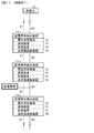
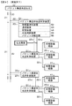
実施例1は、本開示の配電異常検出装置に関する。実施例1の配電異常検出装置等の概念図を図1に示す。また、識別情報を有し、且つ、区画化された電力の概念図を図2の(A)及び(B)に示す。 Example 1 relates to a distribution abnormality detection device of the present disclosure. FIG. 1 is a conceptual diagram of a distribution abnormality detection device and the like according to the first embodiment. 2A and 2B are conceptual diagrams of divided electric power having identification information.
実施例1の配電異常検出装置11(図示した例では、配電異常検出装置111,112,113)は、識別情報を有し、且つ、区画化された電力(具体的には、或る識別情報と、この或る識別情報の次の識別情報とによって挟まれた電力であり、より具体的には、電力量)の配電異常を検出する配電異常検出装置である。配電異常検出装置11は、所定の距離間隔をもって配電線(高圧配電線、幹配電線)20に組み込まれている。そして、配電線20からの電力を配電異常検出装置11内を通過させ、配電異常検出装置11によって識別情報を直接的に検出する。あるいは、配電線20に隣接して配設されており、配電線20を流れる電力から識別情報を間接的に検出する。配電線20には、周知の配電元(例えば、各種発電所や変電所、配電用変電所、柱上変圧器等)10から電力が送られる。
The distribution
実施例1の配電異常検出装置11は、周知の構成、構造を有する電圧測定装置12、周知の構成、構造を有する電力線搬送通信(PLC)技術に基づく通信装置(電力線モデム)13、配電異常検出装置11の識別番号(ID番号)等を記憶した周知の構成、構造を有する記憶装置14、及び、周知の構成、構造を有する送受電遮断装置15を備えている。
A distribution
実施例1にあっては、識別情報と区画化された電力とは、一体となって電力パケットを構成する。ここで、識別情報は電力パケットのヘッダ部に該当し、区画化された電力は電力パケットのペイロード部に該当する。そして、図2の(A)に示すように、電力の配電にあっては、例えば、[第n番目の識別情報(ヘッダ部81)]、[第n番目の区画化された電力(ペイロード部82)]、[第(n+1)番目の識別情報(ヘッダ部81)]、[第(n+1)番目の区画化された電力(ペイロード部82)]、[第(n+2)番目の識別情報(ヘッダ部81)]、[第(n+2)番目の区画化された電力(ペイロード部82)]・・・が、順次、配電線20中を流れる。電力パケットのヘッダ部81の長さ(例えば、バイト数に相当する)、ペイロード部82の長さ(例えば、電力量に相当する)は、本質的に任意であり、所望の値とすることができる。実施例1にあっては、限定するものではないが、ヘッダ部81の長さを64バイトとした。ヘッダ部81は一種のタグとして機能する。また、ペイロード部82の長さを10キロワット(電圧値及び電流値:VPLD=6600ボルトの場合、IPLD=1.515アンペアであり、VPLD=200ボルトの場合、IPLD=50アンペアである)とした。尚、配電線20を交流が流れる場合、電圧値は実効電圧値である。更には、区画化された電力によって規定された間隔を、一定の時間間隔(具体的には、実施例1にあってはT0=1秒間隔)とした。即ち、定常状態にあっては、識別情報(ヘッダ部81)がT0秒間隔で出現する。あるいは又、区画化された電力(電力量)は一定である。あるいは又、区画化された電力によって規定された間隔は、電力パケット長(実施例1にあっては、上記のヘッダ部81及びペイロード部82の合計時間長さであり、一定量)である。
In the first embodiment, the identification information and the partitioned power together constitute a power packet. Here, the identification information corresponds to the header portion of the power packet, and the partitioned power corresponds to the payload portion of the power packet. As shown in FIG. 2A, in power distribution, for example, [nth identification information (header part 81)], [nth partitioned power (payload part) 82)], [(n + 1) th identification information (header portion 81)], [(n + 1) th partitioned power (payload portion 82)], [(n + 2) th identification information (header) Part 81)], [(n + 2) th partitioned power (payload part 82)]... Sequentially flow through the
そして、配電異常検出装置11は、電力配電中に検出した識別情報の間隔が、区画化された電力によって規定された間隔と異なる場合、即ち、識別情報間隔異常が発生した場合、配電異常が発生したと判断(判定、決定)する。ここで、電圧測定装置12は、識別情報(電力パケットのヘッダ部81)に相当する電圧値を検出する。
Then, the distribution
具体的には、配電異常検出装置11は、識別情報(ヘッダ情報)の出現を、逐次、記憶装置14に記憶し、識別情報(ヘッダ情報)がT0秒間隔で出現しない状態が、1回、出現した場合(図2の(B)に示す例では、識別情報(ヘッダ情報)がT1秒>T0秒の間隔で出現)、あるいは、複数回、連続して出現した場合、あるいは、複数回、或る時間内に出現した場合、配電異常検出装置11によって配電異常が発生したと判断される。具体的には、配電線20を流れる電力の電圧値VPLD,VHDRを電圧測定装置12によって測定し、配電異常検出装置11は、電圧値VHDRが出現する時間間隔を測定する。そして、配電異常検出装置11によって配電異常が発生したと判断されたとき、即ち、電圧測定装置12によって測定された電圧値VHDRがT0秒間隔で出現しない状態が生じたとき、配電異常検出装置11は、通信装置13及び有線の通信ライン21を介して、配電異常が発生した旨を、上流に位置する配電異常検出装置11に送信する。尚、有線の通信ライン21の実体は、配電線20である。例えば、配電異常検出装置112と配電異常検出装置113との間で配電異常(例えば、盗電や異常リーク)が発生したとき、この異常は配電異常検出装置113によって検出され、配電異常検出装置112へと知らされる。配電異常検出装置112は送受電遮断装置15を作動させて、配電異常検出装置112から配電異常検出装置113への電力の配電を停止させ、あるいは又、配電異常検出装置112の配電異常検出装置111からの電力の受電を停止させる。
Specifically, the power distribution
実施例1の配電異常検出装置は、電力配電中に識別情報を検出する。そして、何らかの事情によって(例えば、盗電や異常リーク等によって)配電中の電力から識別情報の一部が欠落したとき、配電異常検出装置によって検出される識別情報の間隔が本来の間隔よりも広がり、検出された識別情報の間隔が、区画化された電力によって規定された間隔と異なることになる現象が発生する。それ故、配電異常検出装置は、配電異常が発生したことを容易に判断することができるし、検出された識別情報の間隔は一種のデジタル量であるが故に、配電中の異常発生を瞬時に安定して検出することが可能となる。 The distribution abnormality detection apparatus according to the first embodiment detects identification information during power distribution. And when some of the identification information is lost from the power being distributed for some reason (for example, due to power theft or abnormal leak), the interval of the identification information detected by the distribution abnormality detection device is wider than the original interval, A phenomenon occurs in which the interval of the detected identification information is different from the interval defined by the partitioned power. Therefore, the distribution abnormality detection device can easily determine that a distribution abnormality has occurred, and since the interval of the detected identification information is a kind of digital quantity, an abnormality occurrence during distribution can be instantaneously detected. It becomes possible to detect stably.
実施例2は、本開示の送受電制御装置及び電力供給制御装置に関する。実施例2の送受電制御装置及び電力供給制御装置等の概念図を図3に示す。実施例2の送受電制御装置31は、識別情報を有し、且つ、区画化された電力を送受可能な送受電制御装置であり、実施例2の電力供給制御装置32は、識別情報を有し、且つ、区画化された電力を供給する電力供給制御装置であり、実施例1において説明した配電異常検出装置11を備えている。そして、配電異常検出装置11によって検出された識別情報の間隔が、区画化された電力によって規定された間隔と異なるとき、即ち、識別情報間隔異常が発生した場合、送受電制御装置31あるいは電力供給制御装置32は、電力の送受電あるいは供給を制御する。具体的には、配電異常検出装置11によって配電異常が発生したと判断(判定、決定)された場合、備えられた周知の構成、構造の送受電遮断装置35を作動させて、電力の配電あるいは受電を停止させる。
Example 2 relates to a power transmission and reception control device and a power supply control device of the present disclosure. FIG. 3 shows a conceptual diagram of the power transmission / reception control device and the power supply control device of the second embodiment. The power transmission / reception control device 31 according to the second embodiment has identification information and is a power transmission / reception control device capable of transmitting and receiving partitioned power. The power supply control device 32 according to the second embodiment has identification information. In addition, the power supply control device supplies the partitioned power, and includes the power distribution
送受電制御装置31あるいは電力供給制御装置32は、更に、外部から供給される電力パケットの中のペイロード部から電力を抽出し、ヘッダ部から識別情報を抽出するパケット分解回路、外部から供給される電力を充電する二次電池、外部あるいは二次電池から供給される電力に基づき、受電設備・機器に供給すべき電力を発生させる電力発生装置、パケット分解回路により抽出された電力パケットのヘッダ部から抽出された識別情報をヘッダ部に含む電力パケットを生成するパケット合成回路、電力パケットが受電設備・機器まで伝送される配電ネットワーク(配電路)を記憶する配電路記憶装置を備えていてもよい。 The power transmission / reception control device 31 or the power supply control device 32 further extracts a power from the payload portion in the power packet supplied from the outside, and extracts the identification information from the header portion, and is supplied from the outside. From the secondary battery that charges the power, the power generation device that generates the power to be supplied to the power receiving facility / equipment based on the power supplied from the outside or the secondary battery, the header of the power packet extracted by the packet decomposition circuit A packet combining circuit that generates a power packet including the extracted identification information in a header portion, and a distribution path storage device that stores a distribution network (distribution path) through which the power packet is transmitted to a power receiving facility / device may be provided.
配電異常検出装置11は、送受電制御装置31あるいは電力供給制御装置32とは離れた場所に配設されている。そして、送受電制御装置31あるいは電力供給制御装置32は通信装置33を備えており、配電異常が発生したとの配電異常検出装置11による判断を、配電異常検出装置11から通信ライン21を介して受け取ることができる。送受電制御装置31あるいは電力供給制御装置32は、更に、記憶装置34を備えており、配電異常検出装置11の識別番号が記憶されており、更に、配電異常が発生したと判断した配電異常検出装置11の識別番号を配電異常検出装置11から通信ライン21を介して受け取り、記憶装置34は記憶する。これによって、送受電制御装置31あるいは電力供給制御装置32は、どの配電異常検出装置11と配電異常検出装置11との間の配電線20において、配電異常が発生したかを知ることができる。
The power distribution
尚、配電異常検出装置11は、検出された識別情報の間隔が区画化された電力によって規定された間隔と異なることを、即ち、識別情報間隔異常が発生したことを、送受電制御装置31あるいは電力供給制御装置32に送出し、送受電制御装置31あるいは電力供給制御装置32が、配電異常が発生したことの判断を行ってもよい。
The distribution
実施例2の送受電制御装置あるいは電力供給制御装置にあっても、電力配電中に識別情報を検出する配電異常検出装置を備えている。従って、何らかの事情によって、例えば、盗電や異常リーク等によって配電中の電力から識別情報の一部が欠落したとき、配電異常検出装置によって検出される識別情報の間隔が、本来の間隔よりも広がり、検出された識別情報の間隔が、区画化された電力によって規定された間隔と異なることになる現象が発生する。それ故、送受電制御装置あるいは電力供給制御装置は、配電異常が発生したことを容易に判断することができる。 The power transmission / reception control device or the power supply control device according to the second embodiment also includes a power distribution abnormality detection device that detects identification information during power distribution. Therefore, for some reason, for example, when a part of the identification information is lost from the power being distributed due to power theft, abnormal leakage, etc., the interval of the identification information detected by the distribution abnormality detection device is wider than the original interval, A phenomenon occurs in which the interval of the detected identification information is different from the interval defined by the partitioned power. Therefore, the power transmission / reception control device or the power supply control device can easily determine that a power distribution abnormality has occurred.
実施例3は、実施例1あるいは実施例2の変形である。実施例3の配電異常検出装置、送受電制御装置及び電力供給制御装置等の概念図を図4に示す。 The third embodiment is a modification of the first or second embodiment. FIG. 4 shows a conceptual diagram of a power distribution abnormality detection device, a power transmission / reception control device, a power supply control device, etc.
実施例3にあっては、配電線(高圧配電線)20から複数の低圧配電線(枝配電線、引込み線)22が分岐して延びている。そして、例えば、低圧配電線2211,2212,2213に配電異常検出装置1111,1112が組み込まれており、配電異常検出装置1112に、開閉器4211,4212,4213を介して、受電設備・機器4111,4112,4113が接続されている。同様に、低圧配電線2221,2222,2223に配電異常検出装置1121,1122が組み込まれており、配電異常検出装置1122に、開閉器4221,4222,4223を介して、受電設備・機器4121,4122,4123が接続されている。尚、配電異常検出装置内に開閉器を配設してもよい。
In the third embodiment, a plurality of low-voltage distribution lines (branched distribution lines, lead-in lines) 22 extend from the distribution line (high-voltage distribution line) 20. For example, distribution
配電異常検出装置1112に備えられた記憶装置14には、受電設備・機器4111,4112,4113の受電設備・機器情報(具体的には、受電設備・機器に予め付与されている受電設備・機器の識別番号)が記憶されている。受電設備・機器4111,4112,4113は、受電設備・機器4111,4112,4113に記憶されている受電設備・機器情報を、所定の時間間隔で、通信ライン2313を介して、配電異常検出装置1112に送出しており、配電異常検出装置1112は、受電設備・機器4111,4112,4113が接続されていることを、常に把握している。また、受電設備・機器4113に関する受電設備・機器情報には、電力供給の停止を禁止すべき旨の情報が含まれているとする。
The
同様に、配電異常検出装置1122に備えられた記憶装置14には、受電設備・機器4121,4122,4123の受電設備・機器情報(受電設備・機器の識別番号)が記憶されている。受電設備・機器4121,4122,4123は、受電設備・機器4121,4122,4123に記憶されている受電設備・機器情報を、所定の時間間隔で、通信ライン2323を介して、配電異常検出装置1122に送出しており、配電異常検出装置1122は、受電設備・機器4121,4122,4123が接続されていることを、常に把握している。
Similarly, the
ここで、配電異常検出装置1111と配電異常検出装置1112との間の低圧配電線2212の部分で、配電異常が発生したとする。この配電異常は、実施例1と同様にして、配電異常検出装置1112によって検出され、配電異常が発生したと判断(判定、決定)される。そして、この場合、配電異常検出装置1112は、記憶装置14に記憶された受電設備・機器情報に基づき受電設備・機器への電力の供給を停止させる。具体的には、配電異常検出装置1112の制御下、通信ライン2313を介して、開状態にあった開閉器4211,4212を閉状態とすることで、受電設備・機器4111,4112への電力の供給を停止させる。一方、受電設備・機器4113に関する受電設備・機器情報には、電力供給の停止を禁止すべき旨の情報が含まれているので、開閉器4213は開状態のままとし、受電設備・機器4113へは電力を供給し続ける。
Here, it is assumed that a distribution abnormality has occurred in the portion of the low-
また、実施例3にあっても、実施例2と同様に、配電異常検出装置11は、検出された識別情報の間隔が区画化された電力によって規定された間隔と異なることを、即ち、識別情報間隔異常が発生したことを、送受電制御装置31あるいは電力供給制御装置32に送出し、送受電制御装置31あるいは電力供給制御装置32が、配電異常が発生したことの判断を行ってもよい。そして、この場合には、識別情報間隔異常が発生したことを検出した配電異常検出装置11に対して、受電設備・機器への電力の供給制御の指令を送出すればよい。
Also in the third embodiment, similarly to the second embodiment, the distribution
実施例4も、実施例1あるいは実施例2の変形である。実施例4の配電異常検出装置、送受電制御装置及び電力供給制御装置等の概念図を図5に示す。 The fourth embodiment is also a modification of the first or second embodiment. FIG. 5 shows a conceptual diagram of a power distribution abnormality detection device, a power transmission / reception control device, a power supply control device, etc.
実施例4にあっても、配電線(高圧配電線)20から複数の低圧配電線22が分岐して延びている。そして、例えば、低圧配電線2211,2212,2213に配電異常検出装置1111,1112が組み込まれており、配電異常検出装置1112に、受電設備・機器4111,4112,4113が接続されている。同様に、低圧配電線2221,2222,2223に配電異常検出装置1121,1122が組み込まれており、配電異常検出装置1122に、受電設備・機器4121,4122,4123が接続されている。
Even in the fourth embodiment, a plurality of low-
実施例4にあっては、識別情報に受電設備・機器情報が含まれている。配電異常検出装置に接続された受電設備・機器の全てに対して電力の供給を停止させてよい場合には、この受電設備・機器情報を、例えば「1」とする。一方、配電異常検出装置に接続された受電設備・機器に、電力供給の停止を禁止すべき受電設備・機器が含まれる場合には、この受電設備・機器情報を、例えば「0」とする。更には、識別情報には、これらの受電設備・機器が接続されている配電異常検出装置の識別番号(ID番号)が含まれている。 In the fourth embodiment, the identification information includes power receiving facility / equipment information. When it is possible to stop the supply of power to all the power receiving equipment / devices connected to the power distribution abnormality detection device, the power receiving equipment / device information is set to “1”, for example. On the other hand, when the power receiving facility / device connected to the power distribution abnormality detection device includes a power receiving facility / device that should be prohibited from stopping power supply, the power receiving facility / device information is set to “0”, for example. Furthermore, the identification information includes an identification number (ID number) of the distribution abnormality detecting device to which these power receiving facilities / devices are connected.
ここで、配電異常検出装置1111と配電異常検出装置1112との間の低圧配電線2212の部分で、配電異常が発生したとする。この配電異常は、実施例1と同様にして、配電異常検出装置1112によって検出され、配電異常が発生したと判断(判定、決定)される。そして、この場合、配電異常検出装置1112は、送られてきた電力パケットのヘッダ部(識別情報)を、図示しないパケット分解回路で分解して解析し、送られてきた電力パケットのヘッダ部(識別情報)に、配電異常検出装置1112の識別番号(ID番号)が含まれているか否かを調べる。もしも、配電異常検出装置1112の識別番号(ID番号)が含まれている場合、電力パケットのヘッダ部(識別情報)における受電設備・機器情報が「1」であるか「0」であるかを解析し、「1」である場合、送受電遮断装置15を作動させて、受電設備・機器4121,4122,4123への電力の供給を停止させる。一方、「0」である場合、受電設備・機器4121,4122,4123への電力の供給を継続する。もしも、配電異常検出装置1112の識別番号(ID番号)が含まれていない場合には、送受電遮断装置15を作動させて、受電設備・機器4121,4122,4123への電力の供給を停止させる。
Here, it is assumed that a distribution abnormality has occurred in the portion of the low-
また、実施例4にあっても、実施例2と同様に、配電異常検出装置11は、検出された識別情報の間隔が区画化された電力によって規定された間隔と異なることを、即ち、識別情報間隔異常が発生したことを、送受電制御装置31あるいは電力供給制御装置32に送出し、送受電制御装置31あるいは電力供給制御装置32が、配電異常が発生したことの判断を行ってもよい。そして、この場合には、識別情報間隔異常が発生したことを検出した配電異常検出装置11に対して、受電設備・機器への電力の供給制御の指令を送出すればよい。
Also in the fourth embodiment, similarly to the second embodiment, the distribution
実施例5は、本開示のパケット構造体伝送制御装置に関する。実施例5のパケット構造体伝送制御装置等の概念図を図6に示す。また、パケット構造体の概念図を図7の(A)及び(B)に示す。実施例5のパケット構造体伝送制御装置51は、
(A)物理量で規定されるペイロード、及び、
(B)ペイロードのペイロード長を含むヘッダ情報、
から構成されたパケット構造体の伝送を制御するパケット構造体伝送制御装置である。そして、
パケット構造体伝送制御装置51によって得られたペイロードのペイロード長(実測されたペイロードのペイロード量)に基づくデータと、パケット構造体伝送制御装置51によって得られたヘッダ情報におけるペイロード長(数値データ)に関するデータとが不一致である場合、パケット構造体伝送制御装置51はパケット構造体の伝送に異常が発生したと判断(判定、決定)する。
Example 5 relates to a packet structure transmission control device of the present disclosure. FIG. 6 shows a conceptual diagram of the packet structure transmission control device of the fifth embodiment. A conceptual diagram of the packet structure is shown in FIGS. The packet structure
(A) Payload defined by physical quantity, and
(B) header information including the payload length of the payload,
Is a packet structure transmission control device for controlling transmission of a packet structure composed of And
The data based on the payload length (the payload amount of the actually measured payload) obtained by the packet structure
ここで、実施例5にあっては、具体的には、物理量で規定されるペイロードは電力量であり、ヘッダ情報には、ペイロードのペイロード長である電力量の値(数値データ)が含まれる。 Here, in the fifth embodiment, specifically, the payload defined by the physical quantity is the electric energy, and the header information includes the electric energy value (numerical data) that is the payload length of the payload. .
実施例5のパケット構造体伝送制御装置51(図示した例では、パケット構造体伝送制御装置511,512,513)は、所定の距離間隔をもって配電線(高圧配電線)20に組み込まれている。即ち、配電線20からのパケット構造体(具体的には、電力パケット)をパケット構造体伝送制御装置51内を通過させ、パケット構造体伝送制御装置51によってヘッダ情報を直接的に検出する。あるいは、配電線20に隣接して配設されており、配電線20を流れるパケット構造体からヘッダ情報を間接的に検出する。配電線20には、周知のパケット構造体伝送元(例えば、発電所や変電所等)10’から電力パケットであるパケット構造体が送られる。
The packet structure
実施例5のパケット構造体伝送制御装置51は、物理量測定装置(具体的には、周知の構成、構造を有する電力測定装置)52、周知の構成、構造を有する電力線搬送通信(PLC)技術に基づく通信装置(電力線モデム)53、パケット構造体伝送制御装置51の識別番号(ID番号)等を記憶した周知の構成、構造を有する記憶装置54、周知の構成、構造を有する伝送遮断装置55、及び、周知の構成、構造を有するパケット分解回路56を備えている。
The packet structure
実施例5にあっては、図7の(A)に示すように、パケット構造体の伝送において、例えば、[第n番目のヘッダ情報91]、[第n番目の区画化されたペイロード部92]、[第(n+1)番目のヘッダ情報91]、[第(n+1)番目の区画化されたペイロード部92]、[第(n+2)番目のヘッダ情報91]、[第(n+2)番目の区画化されたペイロード部92)]・・・が、順次、配電線20中を流れる。ヘッダ情報91の長さ(例えば、ビット数、バイト数や時間長さに相当する)、ペイロード部92の物理量(電力量に相当する)は、本質的に任意であり、所望の値とすることができる。
In the fifth embodiment, as shown in FIG. 7A, in transmission of a packet structure, for example, [nth header information 91], [nth partitioned payload section 92] ], [(N + 1) th header information 91], [(n + 1) th partitioned payload section 92], [(n + 2) th header information 91], [(n + 2) th partition] The payload portion 92)]... That flows through the
パケット構造体伝送制御装置51において、物理量測定装置(電力測定装置)52は、物理量で規定されるペイロード、即ち、電力量PW1を測定する。一方、パケット分解回路56はパケット構造体を分解し、解析することで、ペイロードのペイロード長である電力量の値(数値データ)PW2を得る。尚、ヘッダ情報91における電圧値は、高値と低値の組合せから成る。即ち、ヘッダ情報91における電圧値は、複数ビットのバイナリデータから成る。そして、パケット構造体伝送制御装置51は、ペイロードのペイロード長に基づくデータ(具体的には、実測された電力量の値PW1)と、ヘッダ情報におけるペイロード長に関するデータ(具体的には、電力量の数値データPW2)とを比較し、これらの値PW1,PW2が不一致である場合、即ち、ペイロード長不一致が発生した場合、パケット構造体の伝送に異常が発生したと判断する。即ち、図7の(B)に示すように、伝送異常(例えば、盗電や異常リーク)が発生し、電力量PW1の値がPW1’に減少したとすれば、ヘッダ情報におけるペイロード長に関するデータ(具体的には、電力量の数値データPW2)との間に不一致が生じる。そして、このような現象が、例えば、パケット構造体伝送制御装置513で検出されたとき、パケット構造体伝送制御装置513は、通信装置13及び通信ライン21を介して、伝送異常が発生した旨を、上流に位置するパケット構造体伝送制御装置512に送信する。パケット構造体伝送制御装置512は、パケット構造体の伝送を制御する。具体的には、パケット構造体伝送制御装置512は、伝送遮断装置55を作動させて、パケット構造体伝送制御装置512からパケット構造体伝送制御装置513へのパケット構造体の伝送を停止させ、あるいは又、パケット構造体伝送制御装置512へのパケット構造体伝送制御装置511からのパケット構造体の伝送を停止させる。
In the packet structure
実施例5のパケット構造体伝送制御装置にあっては、ペイロードのペイロード長に基づくデータと、ヘッダ情報におけるペイロード長に関するデータとが不一致である場合、パケット構造体の伝送に異常が発生したと判断するので、伝送中の異常発生を瞬時に安定して検出することが可能となる。 In the packet structure transmission control apparatus according to the fifth embodiment, when the data based on the payload length of the payload and the data regarding the payload length in the header information do not match, it is determined that an abnormality has occurred in the transmission of the packet structure. Therefore, it is possible to instantaneously and stably detect the occurrence of abnormality during transmission.
実施例6は、実施例5の変形である。実施例6におけるパケット構造体伝送制御装置等の概念図を図8に示す。 The sixth embodiment is a modification of the fifth embodiment. FIG. 8 shows a conceptual diagram of the packet structure transmission control device and the like in the sixth embodiment.
実施例6にあっては、実施例3と同様に、配電線(高圧配電線)20から複数の低圧配電線22が分岐して延びている。そして、例えば、低圧配電線2211,2212,2213にパケット構造体伝送制御装置5111,5112が組み込まれており、パケット構造体伝送制御装置5112に、開閉器4211,4212,4213を介して、受電設備・機器4111,4112,4113が接続されている。同様に、低圧配電線2221,2222,2223にパケット構造体伝送制御装置5121,5122が組み込まれており、パケット構造体伝送制御装置5122に、開閉器4221,4222,4223を介して、受電設備・機器4121,4122,4123が接続されている。尚、パケット構造体伝送制御装置内に開閉器を配設してもよい。
In the sixth embodiment, similarly to the third embodiment, a plurality of low-
パケット構造体伝送制御装置5112に備えられた記憶装置54には、受電設備・機器4111,4112,4113の受電設備・機器情報(具体的には、受電設備・機器に予め付与されている受電設備・機器の識別番号)が記憶されている。受電設備・機器4111,4112,4113は、受電設備・機器4111,4112,4113に記憶されている受電設備・機器情報を、所定の時間間隔で、通信ライン2313を介して、パケット構造体伝送制御装置5112に送出しており、パケット構造体伝送制御装置5112は、受電設備・機器4111,4112,4113が接続されていることを、常に把握している。また、受電設備・機器4113に関する受電設備・機器情報には、パケット構造体の伝送の停止を禁止すべき旨の情報が含まれているとする。
The
同様に、パケット構造体伝送制御装置5122に備えられた記憶装置54には、受電設備・機器4121,4122,4123の受電設備・機器情報(受電設備・機器の識別番号)が記憶されている。受電設備・機器4121,4122,4123は、受電設備・機器4121,4122,4123に記憶されている受電設備・機器情報を、所定の時間間隔で、通信ライン2323を介して、パケット構造体伝送制御装置5122に送出しており、パケット構造体伝送制御装置5122は、受電設備・機器4121,4122,4123が接続されていることを、常に把握している。
Similarly, the
ここで、パケット構造体伝送制御装置5111とパケット構造体伝送制御装置5112との間の低圧配電線2212の部分で、パケット構造体の伝送異常が発生したとする。この伝送異常は、実施例5と同様にして、パケット構造体伝送制御装置5112によって検出され、伝送異常が発生したと判断(判定、決定)される。そして、この場合、パケット構造体伝送制御装置5112は、記憶装置54に記憶された受電設備・機器情報に基づき受電設備・機器へのパケット構造体の伝送を停止させる。具体的には、パケット構造体伝送制御装置5112の制御下、通信ライン2313を介して、開状態にあった開閉器4211,4212を閉状態とすることで、受電設備・機器4111,4112へのパケット構造体の伝送の供給を停止させる。一方、受電設備・機器4113に関する受電設備・機器情報には、パケット構造体の伝送の停止を禁止すべき旨の情報が含まれているので、開閉器4213は開状態のままとし、受電設備・機器4113へはパケット構造体を伝送し続ける。
Here, the portion of the low-
実施例7も、実施例5の変形である。実施例7のパケット構造体伝送制御装置等の概念図を図9に示す。 The seventh embodiment is also a modification of the fifth embodiment. FIG. 9 shows a conceptual diagram of the packet structure transmission control device of the seventh embodiment.
実施例7にあっても、配電線(高圧配電線)20から複数の低圧配電線22が分岐して延びている。そして、例えば、低圧配電線2211,2212,2213にパケット構造体伝送制御装置5111,5112が組み込まれており、パケット構造体伝送制御装置5112に、受電設備・機器4111,4112,4113が接続されている。同様に、低圧配電線2221,2222,2223にパケット構造体伝送制御装置5121,5122が組み込まれており、パケット構造体伝送制御装置5122に、受電設備・機器4121,4122,4123が接続されている。
Even in the seventh embodiment, a plurality of low-
実施例7にあっては、識別情報に受電設備・機器情報が含まれている。パケット構造体伝送制御装置に接続された受電設備・機器の全てに対してパケット構造体の伝送を停止させてよい場合には、この受電設備・機器情報を、例えば「1」とする。一方、パケット構造体伝送制御装置に接続された受電設備・機器に、パケット構造体の伝送の停止を禁止すべき受電設備・機器が含まれる場合には、この受電設備・機器情報を、例えば「0」とする。更には、識別情報には、これらの受電設備・機器が接続されているパケット構造体伝送制御装置の識別番号(ID番号)が含まれている。 In the seventh embodiment, the identification information includes power receiving facility / equipment information. When the transmission of the packet structure may be stopped for all the power receiving facilities / devices connected to the packet structure transmission control device, the power receiving facility / device information is set to “1”, for example. On the other hand, when the power receiving facility / device connected to the packet structure transmission control device includes a power receiving facility / device that should be prohibited from stopping transmission of the packet structure, the power receiving facility / device information is, for example, “ 0 ”. Furthermore, the identification information includes the identification number (ID number) of the packet structure transmission control apparatus to which these power receiving facilities / devices are connected.
ここで、パケット構造体伝送制御装置5111とパケット構造体伝送制御装置5112との間の低圧配電線2212の部分で、伝送異常が発生したとする。この伝送異常は、実施例5と同様にして、パケット構造体伝送制御装置5112によって検出され、伝送異常が発生したと判断(判定、決定)される。そして、この場合、パケット構造体伝送制御装置5112は、送られてきたパケット構造体のヘッダ情報を、パケット分解回路56で分解して解析し、送られてきたパケット構造体のヘッダ情報に、パケット構造体伝送制御装置5112の識別番号(ID番号)が含まれているか否かを調べる。もしも、パケット構造体伝送制御装置5112の識別番号(ID番号)が含まれている場合、パケット構造体のヘッダ情報における受電設備・機器情報が「1」であるか「0」であるかを解析し、「1」である場合、伝送遮断装置55を作動させて、受電設備・機器4121,4122,4123へのパケット構造体の伝送を停止させる。一方、「0」である場合、受電設備・機器4121,4122,4123へのパケット構造体の伝送を継続する。もしも、パケット構造体伝送制御装置5112の識別番号(ID番号)が含まれていない場合には、伝送遮断装置55を作動させて、受電設備・機器4121,4122,4123へのパケット構造体の伝送を停止させる。
Here, the portion of the low-
以上、本開示を好ましい実施例に基づき説明したが、本開示はこれらの実施例に限定されるものではない。実施例において説明した配電異常検出装置、送受電制御装置、電力供給制御装置、パケット構造体伝送制御装置の構成、構造は例示であり、適宜、変更することができるし、電力、電力パケット、パケット構造体の構成も例示であり、適宜、変更することができる。 While the present disclosure has been described based on the preferred embodiments, the present disclosure is not limited to these embodiments. The configurations and structures of the distribution abnormality detection device, power transmission / reception control device, power supply control device, and packet structure transmission control device described in the embodiments are merely examples, and can be changed as appropriate. The structure of the structure is also an example, and can be changed as appropriate.
尚、本開示は、以下のような構成を取ることもできる。
[1]《配電異常検出装置》
識別情報を有し、且つ、区画化された電力の配電異常を検出する配電異常検出装置であって、
電力配電中に検出した識別情報の間隔が、区画化された電力によって規定された間隔と異なる場合、配電異常が発生したと判断する配電異常検出装置。
[2]区画化された電力によって規定された間隔は、一定の時間間隔である[1]に記載の配電異常検出装置。
[3]区画化された電力は一定である[1]に記載の配電異常検出装置。
[4]識別情報と区画化された電力とは一体となって電力パケットを構成し、
識別情報は、電力パケットのヘッダ部に該当し、
区画化された電力は、電力パケットのペイロード部に該当する[1]に記載の配電異常検出装置。
[5]区画化された電力によって規定された間隔は、電力パケット長である[4]に記載の配電異常検出装置。
[6]配電異常が発生したと判断した場合、電力の配電あるいは受電を停止させる[1]乃至[5]のいずれか1項に記載の配電異常検出装置。
[7]配電異常が発生したと判断した場合、識別情報に含まれる受電設備・機器情報に基づき受電設備・機器への電力の供給を停止させる[1]乃至[5]のいずれか1項に記載の配電異常検出装置。
[8]識別情報に含まれる受電設備・機器情報には、電力供給の停止を禁止すべき受電設備・機器の情報が含まれる[7]に記載の配電異常検出装置。
[9]記憶装置を備え、
配電異常が発生したと判断した場合、記憶装置に記憶された受電設備・機器情報に基づき受電設備・機器への電力の供給を停止させる[1]乃至[5]のいずれか1項に記載の配電異常検出装置。
[10]受電設備・機器情報には、電力供給の停止を禁止すべき受電設備・機器の情報が含まれる[9]に記載の配電異常検出装置。
[11]《送受電制御装置》
識別情報を有し、且つ、区画化された電力を送受可能な送受電制御装置であって、
電力配電中に識別情報を検出する配電異常検出装置を備えており、
配電異常検出装置によって検出された識別情報の間隔が、区画化された電力によって規定された間隔と異なるとき、電力の送受電を制御する送受電制御装置。
[12]《電力供給制御装置》
識別情報を有し、且つ、区画化された電力を供給する電力供給制御装置であって、
電力配電中に識別情報を検出する配電異常検出装置を備えており、
配電異常検出装置によって検出された識別情報の間隔が、区画化された電力によって規定された間隔と異なるとき、電力の供給を制御する電力供給制御装置。
[13]《パケット構造体伝送制御装置》
(A)物理量で規定されるペイロード、及び、
(B)ペイロードのペイロード長を含むヘッダ情報、
から構成されたパケット構造体の伝送を制御するパケット構造体伝送制御装置であって、
パケット構造体伝送制御装置によって得られたペイロードのペイロード長に基づくデータと、パケット構造体伝送制御装置によって得られたヘッダ情報におけるペイロード長に関するデータとが不一致である場合、パケット構造体の伝送に異常が発生したと判断するパケット構造体伝送制御装置。
[14]パケット構造体の伝送に異常が発生したと判断したとき、パケット構造体の伝送を制御する[13]に記載のパケット構造体伝送制御装置。
In addition, this indication can also take the following structures.
[1] << Distribution abnormality detection device >>
A distribution abnormality detection apparatus that has identification information and detects distribution abnormality of partitioned power,
A distribution abnormality detection device that determines that a distribution abnormality has occurred when an interval of identification information detected during power distribution is different from an interval defined by partitioned power.
[2] The distribution abnormality detecting device according to [1], wherein the interval defined by the partitioned power is a constant time interval.
[3] The distribution abnormality detecting device according to [1], wherein the partitioned power is constant.
[4] The identification information and the partitioned power together form a power packet,
The identification information corresponds to the header part of the power packet,
The distribution abnormality detection device according to [1], wherein the partitioned power corresponds to a payload portion of a power packet.
[5] The distribution abnormality detecting device according to [4], wherein the interval defined by the partitioned power is a power packet length.
[6] The distribution abnormality detection device according to any one of [1] to [5], wherein when it is determined that a distribution abnormality has occurred, power distribution or reception is stopped.
[7] If it is determined that a power distribution abnormality has occurred, the power supply to the power receiving facility / device is stopped based on the power receiving facility / device information included in the identification information, according to any one of [1] to [5] The distribution abnormality detection device described.
[8] The distribution abnormality detecting device according to [7], wherein the power receiving facility / device information included in the identification information includes information on a power receiving facility / device whose power supply should be stopped.
[9] A storage device is provided,
When it is determined that a power distribution abnormality has occurred, the power supply to the power receiving facility / device is stopped based on the power receiving facility / device information stored in the storage device. [1] to [5] Distribution abnormality detection device.
[10] The distribution abnormality detecting device according to [9], wherein the power receiving facility / device information includes information on the power receiving facility / device whose power supply should be prohibited from being stopped.
[11] << Power transmission / reception control device >>
A power transmission / reception control device having identification information and capable of transmitting and receiving partitioned power,
Equipped with a power distribution abnormality detection device that detects identification information during power distribution,
A power transmission / reception control device that controls power transmission / reception when an interval of identification information detected by a power distribution abnormality detection device is different from an interval defined by partitioned power.
[12] << Power supply control device >>
A power supply control device that has identification information and supplies partitioned power,
Equipped with a power distribution abnormality detection device that detects identification information during power distribution,
A power supply control device that controls power supply when the interval of identification information detected by the power distribution abnormality detection device is different from the interval defined by the partitioned power.
[13] << Packet structure transmission control device >>
(A) Payload defined by physical quantity, and
(B) header information including the payload length of the payload,
A packet structure transmission control device for controlling transmission of a packet structure composed of:
If the data based on the payload length of the payload obtained by the packet structure transmission control device and the data related to the payload length in the header information obtained by the packet structure transmission control device do not match, there is an error in the transmission of the packet structure. A packet structure transmission control device that determines that a problem has occurred.
[14] The packet structure transmission control device according to [13], which controls transmission of the packet structure when it is determined that an abnormality has occurred in the transmission of the packet structure.
10・・・配電元、10’・・・パケット構造体伝送元、11,111,112,113,1111,1112,1121,1122・・・配電異常検出装置、12・・・電圧測定装置、13,33,53・・・通信装置、14,34,54・・・記憶装置、15,35・・・送受電遮断装置、20,22・・・配電線、21,23・・・通信ライン、31・・・送受電制御装置、32・・・電力供給制御装置、4111,4112,4113,4121,4122,4123・・・受電設備・機器、51,511,512,513,5111,5112,5121,5122・・・パケット構造体伝送制御装置、52・・・物理量測定装置、55・・・伝送遮断装置、56・・・パケット分解回路、81・・・ヘッダ部、91・・・ヘッダ情報、82,92・・・ペイロード部
10 ... distribution source, 10 '... packet structure transmission source, 11, 11 1 , 11 2 , 11 3 , 11 11 , 11 12 , 11 21 , 11 22 ... distribution abnormality detection device, 12. ..
Claims (11)
電力配電中に検出した識別情報の間隔が、区画化された電力によって規定された間隔と異なる場合、配電異常が発生したと判断し、
配電異常が発生したと判断した場合、識別情報に含まれる受電設備・機器情報に基づき受電設備・機器への電力の供給を停止させ、
識別情報に含まれる受電設備・機器情報には、電力供給の停止を禁止すべき受電設備・機器の情報が含まれる配電異常検出装置。 A distribution abnormality detection apparatus that has identification information and detects distribution abnormality of partitioned power,
If the interval of identification information detected during power distribution is different from the interval specified by the partitioned power, it is determined that a distribution error has occurred ,
When it is determined that a power distribution abnormality has occurred, the power supply to the power receiving facility / device is stopped based on the power receiving facility / device information included in the identification information,
A power distribution abnormality detection device in which the power receiving facility / device information included in the identification information includes information on the power receiving facility / device whose power supply should be stopped .
電力配電中に検出した識別情報の間隔が、区画化された電力によって規定された間隔と異なる場合、配電異常が発生したと判断し、
記憶装置を備え、
配電異常が発生したと判断した場合、記憶装置に記憶された受電設備・機器情報に基づき受電設備・機器への電力の供給を停止させ、
受電設備・機器情報には、電力供給の停止を禁止すべき受電設備・機器の情報が含まれる配電異常検出装置。 A distribution abnormality detection apparatus that has identification information and detects distribution abnormality of partitioned power,
If the interval of identification information detected during power distribution is different from the interval specified by the partitioned power, it is determined that a distribution error has occurred,
A storage device,
If it is determined that a power distribution abnormality has occurred, the power supply to the power receiving facility / device is stopped based on the power receiving facility / device information stored in the storage device .
A distribution abnormality detection device in which the power receiving facility / equipment information includes information on the power receiving facility / equipment that should be prohibited from stopping power supply .
識別情報は、電力パケットのヘッダ部に該当し、
区画化された電力は、電力パケットのペイロード部に該当する請求項1又は請求項2に記載の配電異常検出装置。 The identification information and partitioned power together form a power packet,
The identification information corresponds to the header part of the power packet,
The distribution abnormality detection device according to claim 1 or 2 , wherein the partitioned power corresponds to a payload portion of a power packet.
電力配電中に識別情報を検出する配電異常検出装置を備えており、
配電異常検出装置によって検出された識別情報の間隔が、区画化された電力によって規定された間隔と異なるとき、配電異常が発生したと判断し、
配電異常が発生したと判断した場合、識別情報に含まれる受電設備・機器情報に基づき受電設備・機器への電力の供給を停止させ、
識別情報に含まれる受電設備・機器情報には、電力供給の停止を禁止すべき受電設備・機器の情報が含まれる送受電制御装置。 A power transmission / reception control device having identification information and capable of transmitting and receiving partitioned power,
Equipped with a power distribution abnormality detection device that detects identification information during power distribution,
When the interval of identification information detected by the distribution abnormality detection device is different from the interval defined by the partitioned power, it is determined that a distribution abnormality has occurred,
When it is determined that a power distribution abnormality has occurred, the power supply to the power receiving facility / device is stopped based on the power receiving facility / device information included in the identification information,
A power transmission / reception control device in which the power receiving facility / device information included in the identification information includes information on the power receiving facility / device whose power supply should not be stopped .
電力配電中に識別情報を検出する配電異常検出装置を備えており、Equipped with a power distribution abnormality detection device that detects identification information during power distribution,
配電異常検出装置によって検出された識別情報の間隔が、区画化された電力によって規定された間隔と異なるとき、配電異常が発生したと判断し、When the interval of identification information detected by the distribution abnormality detection device is different from the interval defined by the partitioned power, it is determined that a distribution abnormality has occurred,
記憶装置を備え、A storage device,
配電異常が発生したと判断した場合、記憶装置に記憶された受電設備・機器情報に基づき受電設備・機器への電力の供給を停止させ、If it is determined that a power distribution abnormality has occurred, the power supply to the power receiving facility / device is stopped based on the power receiving facility / device information stored in the storage device.
受電設備・機器情報には、電力供給の停止を禁止すべき受電設備・機器の情報が含まれる送受電制御装置。A power transmission / reception control device in which the power receiving facility / device information includes information on a power receiving facility / device whose power supply should not be stopped.
電力配電中に識別情報を検出する配電異常検出装置を備えており、
配電異常検出装置によって検出された識別情報の間隔が、区画化された電力によって規定された間隔と異なるとき、配電異常が発生したと判断し、
配電異常が発生したと判断した場合、識別情報に含まれる受電設備・機器情報に基づき受電設備・機器への電力の供給を停止させ、
識別情報に含まれる受電設備・機器情報には、電力供給の停止を禁止すべき受電設備・機器の情報が含まれる電力供給制御装置。 A power supply control device that has identification information and supplies partitioned power,
Equipped with a power distribution abnormality detection device that detects identification information during power distribution,
When the interval of identification information detected by the distribution abnormality detection device is different from the interval defined by the partitioned power, it is determined that a distribution abnormality has occurred,
When it is determined that a power distribution abnormality has occurred, the power supply to the power receiving facility / device is stopped based on the power receiving facility / device information included in the identification information,
A power supply control device in which the power receiving facility / device information included in the identification information includes information on a power receiving facility / device that should be prohibited from stopping power supply.
電力配電中に識別情報を検出する配電異常検出装置を備えており、Equipped with a power distribution abnormality detection device that detects identification information during power distribution,
配電異常検出装置によって検出された識別情報の間隔が、区画化された電力によって規定された間隔と異なるとき、配電異常が発生したと判断し、When the interval of identification information detected by the distribution abnormality detection device is different from the interval defined by the partitioned power, it is determined that a distribution abnormality has occurred,
記憶装置を備え、A storage device,
配電異常が発生したと判断した場合、記憶装置に記憶された受電設備・機器情報に基づき受電設備・機器への電力の供給を停止させ、If it is determined that a power distribution abnormality has occurred, the power supply to the power receiving facility / device is stopped based on the power receiving facility / device information stored in the storage device.
受電設備・機器情報には、電力供給の停止を禁止すべき受電設備・機器の情報が含まれる電力供給制御装置。A power supply control device in which the power receiving facility / device information includes information on a power receiving facility / device whose power supply should not be stopped.
Priority Applications (3)
| Application Number | Priority Date | Filing Date | Title |
|---|---|---|---|
| JP2012049279A JP5880147B2 (en) | 2012-03-06 | 2012-03-06 | Distribution abnormality detection device, power transmission / reception control device, and power supply control device |
| CN201310057448.2A CN103312033B (en) | 2012-03-06 | 2013-02-22 | Distribution abnormal detector and power transmission and receiving control device |
| US13/779,110 US9568559B2 (en) | 2012-03-06 | 2013-02-27 | Distribution abnormality detecting device, power transmission and reception control device, power supply control device, and packet structure transmission control device |
Applications Claiming Priority (1)
| Application Number | Priority Date | Filing Date | Title |
|---|---|---|---|
| JP2012049279A JP5880147B2 (en) | 2012-03-06 | 2012-03-06 | Distribution abnormality detection device, power transmission / reception control device, and power supply control device |
Publications (3)
| Publication Number | Publication Date |
|---|---|
| JP2013187946A JP2013187946A (en) | 2013-09-19 |
| JP2013187946A5 JP2013187946A5 (en) | 2015-03-12 |
| JP5880147B2 true JP5880147B2 (en) | 2016-03-08 |
Family
ID=49113450
Family Applications (1)
| Application Number | Title | Priority Date | Filing Date |
|---|---|---|---|
| JP2012049279A Expired - Fee Related JP5880147B2 (en) | 2012-03-06 | 2012-03-06 | Distribution abnormality detection device, power transmission / reception control device, and power supply control device |
Country Status (3)
| Country | Link |
|---|---|
| US (1) | US9568559B2 (en) |
| JP (1) | JP5880147B2 (en) |
| CN (1) | CN103312033B (en) |
Families Citing this family (11)
| Publication number | Priority date | Publication date | Assignee | Title |
|---|---|---|---|---|
| WO2014137845A1 (en) * | 2013-03-04 | 2014-09-12 | University Of Vermont And State Agricultural College | Systems and methods for random-access power management using packetization |
| CA2936847C (en) * | 2014-01-19 | 2022-08-30 | VoltServer, Inc. | Digital power network method and apparatus |
| CN104158298A (en) * | 2014-09-03 | 2014-11-19 | 国家电网公司 | Abnormal event recognizing method and device for dispatching automation system |
| AU2017330374C1 (en) | 2016-09-21 | 2022-10-27 | University Of Vermont And State Agricultural College | Systems and methods for randomized, packet-based power management of conditionally-controlled loads and bi-directional distributed energy storage systems |
| US11150618B2 (en) | 2016-09-21 | 2021-10-19 | University Of Vermont And State Agricultural College | Packetized energy management control systems and methods of using the same |
| JP6642730B2 (en) * | 2016-10-07 | 2020-02-12 | 住友電気工業株式会社 | Judgment device and monitoring device |
| CN110325110B (en) | 2016-11-10 | 2022-08-09 | 纽约州立大学研究基金会 | Systems, methods, and biomarkers for airway obstruction |
| DE102018126078A1 (en) * | 2018-10-19 | 2020-04-23 | Endress+Hauser Conducta Gmbh+Co. Kg | Procedure for handling exceptional conditions in a measuring system |
| CN109596999B (en) * | 2019-01-19 | 2023-12-12 | 重庆山外山血液净化技术股份有限公司 | Power supply monitoring unit of blood purifying equipment |
| US20220393455A1 (en) * | 2019-11-06 | 2022-12-08 | Hubbell Incorporated | Arc fault detection and protection in a digital electricity power distribution system |
| CN111711190A (en) * | 2020-06-18 | 2020-09-25 | 国网河北省电力有限公司石家庄供电分公司 | Electric power stabilizing system and electric power stabilizing method thereof |
Family Cites Families (9)
| Publication number | Priority date | Publication date | Assignee | Title |
|---|---|---|---|---|
| US5214595A (en) * | 1988-05-16 | 1993-05-25 | Hitachi, Ltd. | Abnormality diagnosing system and method for a high voltage power apparatus |
| JPH0738011B2 (en) * | 1988-05-16 | 1995-04-26 | 株式会社日立製作所 | Abnormality diagnosis system for high-voltage power equipment |
| JP2003021649A (en) | 2001-07-10 | 2003-01-24 | Fuji Electric Co Ltd | Electricity stealing prevention device, electricity stealing prevention method and program for executing method by computer |
| JP2006303703A (en) * | 2005-04-18 | 2006-11-02 | Mitsubishi Electric Corp | Network relaying apparatus |
| JP5194435B2 (en) * | 2006-11-08 | 2013-05-08 | ソニー株式会社 | Power supply system, power supply method, power supply program, and server |
| JP2008131443A (en) * | 2006-11-22 | 2008-06-05 | Hitachi Ltd | Monitoring system, and its failure status display method |
| JP5156332B2 (en) * | 2007-10-30 | 2013-03-06 | アラクサラネットワークス株式会社 | Packet transfer device |
| JP2011142771A (en) * | 2010-01-08 | 2011-07-21 | Yokogawa Electric Corp | Power packet system |
| JP2011155710A (en) * | 2010-01-25 | 2011-08-11 | Sony Corp | Power management apparatus, electronic apparatus, and method of managing power |
-
2012
- 2012-03-06 JP JP2012049279A patent/JP5880147B2/en not_active Expired - Fee Related
-
2013
- 2013-02-22 CN CN201310057448.2A patent/CN103312033B/en not_active Expired - Fee Related
- 2013-02-27 US US13/779,110 patent/US9568559B2/en not_active Expired - Fee Related
Also Published As
| Publication number | Publication date |
|---|---|
| CN103312033A (en) | 2013-09-18 |
| US20130234535A1 (en) | 2013-09-12 |
| JP2013187946A (en) | 2013-09-19 |
| CN103312033B (en) | 2017-12-26 |
| US9568559B2 (en) | 2017-02-14 |
Similar Documents
| Publication | Publication Date | Title |
|---|---|---|
| JP5880147B2 (en) | Distribution abnormality detection device, power transmission / reception control device, and power supply control device | |
| EP3397976B1 (en) | Reefer receptacle with system for testing electrical connectors | |
| JP2010156694A (en) | Meter phase identification | |
| CN102625916A (en) | Electrical power system sensor devices, electrical power system monitoring methods, and electrical power system monitoring systems | |
| CA3035227C (en) | Arc detection in electric meter systems | |
| JP2010011558A (en) | Remote meter reading system | |
| KR20120125841A (en) | Monitoring apparatus of power | |
| JP2012105463A (en) | Failure determination system | |
| Bindhu et al. | Effective automatic fault detection in transmission lines by hybrid model of authorization and distance calculation through impedance variation | |
| CN105493382A (en) | Voltage control apparatus and voltage monitoring method | |
| CN108885234A (en) | Adapter for detecting electric equipment | |
| KR20110022904A (en) | System for detecting fault of distribution line | |
| CN105911376B (en) | Active excitation type multi-frequency induced current cable identification method and device | |
| WO2022149012A1 (en) | Submetering system | |
| KR101184160B1 (en) | Method for remote monitering of micro grid electric power quality and thereof for system | |
| Knapek et al. | Communications-capable fault indicators improve outage response for coastal Oregon | |
| KR101644220B1 (en) | System Monitoring Deterioration of Cable Joint and Method for Controlling The Same | |
| CN109313228A (en) | Electrical network check device | |
| KR101274166B1 (en) | System and method for distinguishing the phase of wires | |
| CN109375134A (en) | Generator outlet voltage transformer internal fault on-line monitoring method and system | |
| US10962608B1 (en) | High-impedance fault detection using wireless current transformers | |
| KR20180110949A (en) | Electrical energy management system | |
| US20200099248A1 (en) | Controlled Low Voltage Emergency Power Distribution | |
| CN106324434B (en) | A kind of electrical cable intelligent fortune detecting method | |
| Cho et al. | Distributed and autonomous control system for voltage regulation in low-voltage DC distribution systems |
Legal Events
| Date | Code | Title | Description |
|---|---|---|---|
| A521 | Request for written amendment filed |
Free format text: JAPANESE INTERMEDIATE CODE: A523 Effective date: 20150122 |
|
| A621 | Written request for application examination |
Free format text: JAPANESE INTERMEDIATE CODE: A621 Effective date: 20150122 |
|
| A977 | Report on retrieval |
Free format text: JAPANESE INTERMEDIATE CODE: A971007 Effective date: 20151023 |
|
| A131 | Notification of reasons for refusal |
Free format text: JAPANESE INTERMEDIATE CODE: A131 Effective date: 20151104 |
|
| A521 | Request for written amendment filed |
Free format text: JAPANESE INTERMEDIATE CODE: A523 Effective date: 20151214 |
|
| TRDD | Decision of grant or rejection written | ||
| A01 | Written decision to grant a patent or to grant a registration (utility model) |
Free format text: JAPANESE INTERMEDIATE CODE: A01 Effective date: 20160105 |
|
| A61 | First payment of annual fees (during grant procedure) |
Free format text: JAPANESE INTERMEDIATE CODE: A61 Effective date: 20160118 |
|
| R151 | Written notification of patent or utility model registration |
Ref document number: 5880147 Country of ref document: JP Free format text: JAPANESE INTERMEDIATE CODE: R151 |
|
| R250 | Receipt of annual fees |
Free format text: JAPANESE INTERMEDIATE CODE: R250 |
|
| R250 | Receipt of annual fees |
Free format text: JAPANESE INTERMEDIATE CODE: R250 |
|
| LAPS | Cancellation because of no payment of annual fees |