JP5877323B2 - Optical absolute encoder and device - Google Patents
Optical absolute encoder and device Download PDFInfo
- Publication number
- JP5877323B2 JP5877323B2 JP2011124810A JP2011124810A JP5877323B2 JP 5877323 B2 JP5877323 B2 JP 5877323B2 JP 2011124810 A JP2011124810 A JP 2011124810A JP 2011124810 A JP2011124810 A JP 2011124810A JP 5877323 B2 JP5877323 B2 JP 5877323B2
- Authority
- JP
- Japan
- Prior art keywords
- signal
- offset
- abnormality
- sine wave
- value
- Prior art date
- Legal status (The legal status is an assumption and is not a legal conclusion. Google has not performed a legal analysis and makes no representation as to the accuracy of the status listed.)
- Active
Links
Images

Description
本発明は、サーボモータの回転位置検出に用いる光学式アブソリュートエンコーダにおいて、光学系の異常を検出する。 The present invention detects an abnormality of an optical system in an optical absolute encoder used for detecting a rotational position of a servo motor.
従来、半導体製造装置やロボット、各種工作機械などのFA(Factory Automation)システム装置などの装置には高精度の位置決め制御を行うため、サーボモータが広く利用されている。サーボモータの回転位置の検出には光学式エンコーダが幅広く用いられており、発光素子と受光素子の光軸上にスリット部及び非スリット部を設けた回転板を配置し、発光素子からの光が回転板の位置によってスリット部を透過又は非スリット部を非透過とする構成を設けて、受光素子で光の強弱を検出することによって回転位置を検出している。近年では高分解能化のため、回転板スリット間の周期に合わせて90度位相差の正弦波信号が出力されるようにスリット形状を構成し、内挿演算を行うことで更に分解能を高めたエンコーダが主流となってきている。 2. Description of the Related Art Conventionally, servo motors have been widely used in devices such as FA (Factory Automation) system devices such as semiconductor manufacturing devices, robots, and various machine tools in order to perform high-precision positioning control. Optical encoders are widely used to detect the rotational position of a servo motor. A rotating plate with slits and non-slits is placed on the optical axis of the light emitting element and the light receiving element, and the light from the light emitting element is received. A configuration in which the slit portion is transmitted or the non-slit portion is not transmitted depending on the position of the rotating plate is provided, and the rotational position is detected by detecting the intensity of light with the light receiving element. In recent years, for higher resolution, the slit shape is configured so that a sine wave signal with a phase difference of 90 degrees is output in accordance with the period between the rotating plate slits, and the encoder further improves the resolution by performing interpolation. Has become mainstream.
光学式エンコーダにはインクリメンタルエンコーダとアブソリュートエンコーダがあり、インクリメンタルエンコーダは原点となる1回転で1パルスのZ相と、1回転でNパルスのA相と、A相に対して90度位相差のあるB相パルスで構成されたものであり、Z相を基準の原点としてA/B相によるインクリメンタルカウンタで位置を検出する。更にモータの磁極位置を示すコミュテーションセンサを備えており、3相モータではモータの逆起電力の位相に合わせて120度の位相差をもった3つの信号で構成され、原点が通過するまで不明となる位置をコミュテーションセンサで補っている。 The optical encoder includes an incremental encoder and an absolute encoder. The incremental encoder has a phase difference of 90 degrees with respect to the A phase and the Z phase of 1 pulse per rotation and the A phase of N pulses per rotation. It is composed of B-phase pulses, and the position is detected by an A / B-phase incremental counter with the Z-phase as a reference origin. It also has a commutation sensor that indicates the magnetic pole position of the motor. In a three-phase motor, it consists of three signals with a phase difference of 120 degrees according to the phase of the back electromotive force of the motor, and it is unknown until the origin passes This position is compensated by a commutation sensor.
一方、アブソリュートエンコーダは、回転板の円周上にN個のトラックでグレーコードを出力するようにスリットを設けられており、電源投入時から1回転上の任意の位置が検出できるため、コミュテーションセンサが不要である。 On the other hand, the absolute encoder is provided with a slit on the circumference of the rotating plate to output gray code with N tracks, and can detect any position on one rotation from the time of power-on. No sensor is required.
これらの光学式エンコーダには様々な異常検出手段が設けられているが、発光素子の不点灯ではインクリメンタルエンコーダにおいては3つのコミュテーションセンサの組み合わせが全てHまたはLとならないことを利用して異常を検出することは公知の技術である。(例えば特許文献1) These optical encoders are provided with various abnormality detection means. However, when the light emitting element is not lit, an abnormality is detected by utilizing that the combination of the three commutation sensors does not become H or L in the incremental encoder. Detecting is a known technique. (For example, Patent Document 1)
しかしながら、上述の手法はコミュテーションセンサを有するインクリメンタルエンコーダでは有効であるが、アブソリュートエンコーダにはコミュテーションセンサがないため、発光素子の異常を検出することができないという課題があった。 However, although the above-described method is effective in an incremental encoder having a commutation sensor, there is a problem that an abnormality of a light emitting element cannot be detected because an absolute encoder does not have a commutation sensor.
本発明は上述従来の課題を解決するものであり、90度位相差の2つの正弦波信号を内挿演算することによって高分解能で回転位置を検出する光学式エンコーダにおいて、光学系の異常を検出することを目的とする。 The present invention solves the above-described conventional problems, and detects an optical system abnormality in an optical encoder that detects a rotational position with high resolution by interpolating two sine wave signals having a phase difference of 90 degrees. The purpose is to do.
上記課題を解決するために、第1の発明のアブソリュートエンコーダは、回転板へ発光する発光素子と、前記回転板のスリットを1回転でN等分に分割して生成する1回転上位データと、前記N等分に分割された間隔に同期した1回転でNサイクルの90度位相差の2つの正弦波信号を用いて内挿演算を行うことによって生成される1回転下位データと、前記1回転上位データと前記1回転下位データを合成して1回転位置データを生成する光学式アブソリュートエンコーダにおいて、
前記90度位相差の2つの正弦波信号をそれぞれ2乗して加算する2乗和演算器と、信号の異常しきい値を記録する異常信号メモリと、信号の異常を判定する異常判定器からなり、
前記2乗和演算器で求めた演算結果が、前記異常信号メモリに記録した値より下回った場合に前記異常判定器が異常信号を出力して前記発光素子が不点灯である状態を判定することを特徴とする。
In order to solve the above-mentioned problem, an absolute encoder according to a first aspect of the present invention includes a light emitting element that emits light to a rotating plate, one rotation upper data generated by dividing the slit of the rotating plate into N equal parts by one rotation, One rotation subordinate data generated by performing an interpolation operation using two sine wave signals having a 90-degree phase difference of N cycles in one rotation synchronized with the N-divided interval, and the one rotation In an optical absolute encoder that synthesizes high-order data and the low-speed data and generates single-rotation position data,
From a square sum calculator that squares and adds two sine wave signals having a phase difference of 90 degrees, an abnormal signal memory that records a signal abnormal threshold value, and an abnormality determiner that determines signal abnormality Become
When the calculation result obtained by the square sum calculator is lower than the value recorded in the abnormal signal memory, the abnormality determiner outputs an abnormal signal to determine a state where the light emitting element is not lit. It is characterized by.
また、この発明のアブソリュートエンコーダは、回転板へ発光する発光素子と、前記回転板のスリットを1回転でN等分に分割して生成する1回転上位データと、前記N等分に
分割された間隔に同期した1回転でNサイクルの90度位相差の2つの正弦波信号を用いて内挿演算を行うことによって生成される1回転下位データと、前記1回転上位データと前記1回転下位データを合成して1回転位置データを生成する光学式アブソリュートエンコーダにおいて、
前記90度位相差の2つの正弦波信号のそれぞれ最大値、最小値を検出する振幅検出器と、前記振幅検出器で検出した最大値と最小値から正弦波信号の中心値を演算するオフセット演算器と、前記オフセット演算器で求めた結果を記録するオフセットメモリと、前記90度位相差の2つの正弦波信号をそれぞれ2乗して加算する2乗和演算器と、前記2つの正弦波信号のそれぞれの中心値と振幅値と位相許容とを考慮した許容すべき誤差より小さく設定した前記2つの正弦波信号の異常しきい値を記録する異常信号メモリと、前記2つの正弦波信号の異常を判定する異常判定器からなり、前記2つの正弦波信号は前記光学式アブソリュートエンコーダの製造時または前記光学式アブソリュートエンコーダの前回電源投入時の前記オフセットメモリで記憶した中心値を用いてオフセットのずれを補正した後、前記2乗和演算器でそれぞれ2乗して加算した演算結果が、前記異常信号メモリに記録した前記異常しきい値より下回った場合に前記異常判定器が異常信号を出力して前記発光素子が不点灯である状態を判定する。
The absolute encoder according to the present invention is divided into the light emitting element that emits light to the rotating plate, the upper rotation data generated by dividing the slit of the rotating plate into N equal parts by one rotation, and the N equal parts. One rotation lower data generated by performing an interpolation operation using two sine wave signals having a 90-degree phase difference of N cycles in one rotation synchronized with the interval, the one rotation upper data, and the one rotation lower data In an optical absolute encoder that generates 1 rotation position data by combining
An amplitude detector that detects the maximum and minimum values of the two sine wave signals having a phase difference of 90 degrees, and an offset calculation that calculates the center value of the sine wave signal from the maximum and minimum values detected by the amplitude detector. , An offset memory that records the result obtained by the offset calculator, a square sum calculator that squares and adds the two sine wave signals having a phase difference of 90 degrees, and the two sine wave signals An abnormal signal memory for recording an abnormal threshold value of the two sine wave signals set to be smaller than an allowable error in consideration of a center value, an amplitude value, and a phase allowance of each of the two, and an abnormality of the two sine wave signals consists abnormality determiner determining, said two sine wave signals the offset main at the previous power-up during manufacture or the optical absolute encoder of the optical absolute encoder After correcting the deviation of the offset using the center value stored in Li, the square sum calculator in the calculation result of adding by squaring each of which drops below the abnormality threshold value recorded in the abnormality signal memory In this case, the abnormality determiner outputs an abnormality signal to determine a state where the light emitting element is not lit.
第1の発明の光学式エンコーダ(アブソリュートエンコーダ)によれば、内挿演算で使用する90度位相差の2つの正弦波信号を用いて、それぞれの正弦波信号を2乗して加算した結果により光学系の異常を検出することができるので、部品を追加することなく容易な手段で異常の診断を行うことができる。 According to the optical encoder (absolute encoder) of the first invention, the two sine wave signals having a phase difference of 90 degrees used in the interpolation calculation are squared and added to each other. Since the abnormality of the optical system can be detected, the abnormality can be diagnosed by an easy means without adding parts.
また、この発明の光学式エンコーダ(アブソリュートエンコーダ)によれば、製造工程や部品のばらつきによって生じる90度位相差の2つの正弦波信号のオフセット値のずれを、製造時に測定して記憶し、記憶したオフセット値を用いて演算を行うため、正弦波信号の振幅レベルが小さい場合にも光学系の異常を誤検出することなく、精度よく異常の診断を行うことができる。
Further, according to the optical encoder (absolute encoder) of the present invention, the deviation of the offset value of the two sine wave signals having a phase difference of 90 degrees caused by the manufacturing process and the variation of the parts is measured and stored at the time of manufacturing. Since the calculation is performed using the offset value, even when the amplitude level of the sine wave signal is small, the abnormality can be diagnosed with high accuracy without erroneously detecting an abnormality in the optical system.
従って、容易な手段で光学系の異常を正確に診断することができるため、異常検出能力に優れた光学式エンコーダを提供することができる。 Therefore, since an optical system abnormality can be accurately diagnosed by an easy means, an optical encoder having excellent abnormality detection capability can be provided.
第1の発明は、回転板へ発光する発光素子と、前記回転板のスリットを1回転でN等分に分割して生成する1回転上位データと、前記N等分に分割された間隔に同期した1回転で
Nサイクルの90度位相差の2つの正弦波信号を用いて内挿演算を行うことによって生成される1回転下位データと、前記1回転上位データと前記1回転下位データを合成して1回転位置データを生成する光学式アブソリュートエンコーダにおいて、前記90度位相差の2つの正弦波信号をそれぞれ2乗して加算する2乗和演算器と、信号の異常しきい値を記録する異常信号メモリと、信号の異常を判定する異常判定器からなり、前記2乗和演算器で求めた演算結果が、前記異常信号メモリに記録した値より下回った場合に前記異常判定器が異常信号を出力するため、部品を追加することなく容易な手段で発光素子が不点灯である異常の診断を行うことができる。
The first invention is synchronized with the light emitting element that emits light to the rotating plate, the upper rotation data generated by dividing the slit of the rotating plate into N equal parts by one rotation, and the interval divided into the N equal parts. 1 rotation low-order data generated by performing an interpolation operation using two sine wave signals of 90 degrees phase difference of N cycles in 1 rotation, the 1 rotation high-order data and the 1 rotation low-order data are synthesized. In an optical absolute encoder that generates one rotation position data, a square sum calculator that squares and adds the two sine wave signals having a phase difference of 90 degrees, and an abnormality that records an abnormal threshold value of the signal A signal memory and an abnormality determination unit for determining an abnormality of the signal, and when the calculation result obtained by the sum of squares operator is lower than a value recorded in the abnormality signal memory, the abnormality determination unit outputs an abnormality signal. To output , Can be diagnosed of the light emitting element is abnormal is not turned on at easy means without additional components.
また、この発明は、回転板へ発光する発光素子と、前記回転板のスリットを1回転でN等分に分割して生成する1回転上位データと、前記N等分に分割された間隔に同期した1回転でNサイクルの90度位相差の2つの正弦波信号を用いて内挿演算を行うことによって生成される1回転下位データと、前記1回転上位データと前記1回転下位データを合成して1回転位置データを生成する光学式アブソリュートエンコーダにおいて、前記90度位相差の2つの正弦波信号のそれぞれ最大値、最小値を検出する振幅検出器と、前記振幅検出器で検出した最大値と最小値から正弦波信号の中心値を演算するオフセット演算器と、前記オフセット演算器で求めた結果を記録するオフセットメモリと、前記90度位相差の2つの正弦波信号をそれぞれ2乗して加算する2乗和演算器と、前記2つの正弦波信号のそれぞれの中心値と振幅値と位相許容とを考慮した許容すべき誤差より小さく設定した前記2つの正弦波信号の異常しきい値を記録する異常信号メモリと、前記2つの正弦波信号の異常を判定する異常判定器からなり、前記2つの正弦波信号は前記光学式アブソリュートエンコーダの製造時または前記光学式アブソリュートエンコーダの前回電源投入時の前記オフセットメモリで記憶した中心値を用いてオフセットのずれを補正した後、前記2乗和演算器でそれぞれ2乗して加算した演算結果が、前記異常信号メモリに記録した前記
異常しきい値より下回った場合に前記異常判定器が異常信号を出力するため、正弦波信号の振幅レベルが小さい場合にも光学系の異常を誤検出することなく、精度よく発光素子が不点灯である異常の診断を行うことができる。
In addition, the present invention is synchronized with the light emitting element that emits light to the rotating plate, the upper rotation data generated by dividing the slit of the rotating plate into N equal parts by one rotation, and the interval divided into the N equal parts. 1 rotation low-order data generated by performing an interpolation operation using two sine wave signals of 90 degrees phase difference of N cycles in 1 rotation, the 1 rotation high-order data and the 1 rotation low-order data are synthesized. In an optical absolute encoder that generates one rotation position data, an amplitude detector that detects a maximum value and a minimum value of each of the two sine wave signals having a phase difference of 90 degrees, and a maximum value detected by the amplitude detector, An offset calculator that calculates the center value of the sine wave signal from the minimum value, an offset memory that records the result obtained by the offset calculator, and the two sine wave signals having a phase difference of 90 degrees, And square sum calculator for summing and multiplication, and abnormality of each of the center value and the amplitude value and phase allowed the and set smaller than the error should be acceptable considering two sinusoidal signals of the two sine wave signals and the abnormal signal memory which records the threshold, the consists of two abnormality determiner that determines an abnormality in the sine wave signal, the two sine wave signals last during manufacture or the optical absolute encoder of the optical absolute encoder wherein after correcting the deviation of the offset using the power center value stored in the offset memory when turned, the square sum calculator in the calculation result of adding by squaring each of which was recorded in the abnormal signal memory
Since the abnormality determiner when drops below the abnormal threshold value to output an abnormality signal, without erroneously detected abnormality of the optical system even when the amplitude level of the sine wave signal is small, precisely-emitting element is unlit It is possible to diagnose an abnormality that is.
以下、本発明の実施例について、図面を参照しながら説明する。なお、この実施の形態によって本発明が限定されるものではない。 Embodiments of the present invention will be described below with reference to the drawings. Note that the present invention is not limited to the embodiments.
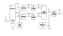
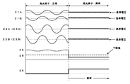
本発明による光学式エンコーダについて、図1と図2を用いて説明する。図1は実施例1における光学式エンコーダの異常検出部のブロック図、図2は光学式エンコーダの異常検出部の動作波形であり、以下に各動作について説明する。 An optical encoder according to the present invention will be described with reference to FIGS. FIG. 1 is a block diagram of an abnormality detector of the optical encoder according to the first embodiment. FIG. 2 is an operation waveform of the abnormality detector of the optical encoder. Each operation will be described below.
図1において符号の1は発光素子、符号の2は回転板、符号の3は受光素子であり、回転板2に設けられたスリットによって発光素子1からの光の強弱を受光素子3が検出し、図2に示すような正弦波波形のSIN原信号21AとCOS原信号21Bを生成する。
In FIG. 1,
符号の4は増幅器、符号の11は基準電圧であり、増幅器4は受光素子3から出力されたSIN原信号21AとCOS原信号を、基準電圧11を中心とした正弦波信号となるように推移させて増幅させて図2に示すような増幅後SIN信号22A、増幅後COS信号22Bを生成する。また、本実施例においては、SINオフセット選択値33Aと、COSオフセット選択値33Bと、COS振幅値30Bと、SIN振幅値30Aと、異常判定器10とを具備している。
符号の5はアナログ信号をディジタルに変換するAD変換器であり、増幅後SIN信号22A、増幅後COS信号22Bのアナログ信号をディジタルに変換し、AD変換後SIN信号23A、AD変換後COS信号23Bを生成する。AD変換後の信号は基準電圧11の電圧をゼロとして、基準電圧より大きい場合を正信号、基準電圧11より小さい場合を負信号として扱う。
符号の8は2乗和演算器であり、AD変換後SIN信号23AとAD変換後COS信号23Bのそれぞれの信号を2乗して加算し、2乗和信号25を生成する。AD変換後SIN信号23AとAD変換後のCOS信号の中心値と振幅値が等しく、位相が90度の場合には2乗和信号25は直線(DC)となるが、これらに誤差がある場合には図2の左側に示すように周期的に変動した波形となる。
符号の9は異常信号メモリであり、不揮発性メモリで構成され、エンコーダの異常を判定するための異常信号しきい値28があらかじめ記憶されている。異常信号しきい値28は、AD変換後SIN信号23AとAD変換後COS信号の中心値や振幅値、位相の許容すべき誤差が生じた場合より小さく設定する。
符号の10は異常判定器であり、2乗和演算器8から出力された2乗和信号25と、異常信号メモリ9から出力された異常信号しきい値28の大小を比較し、2乗和信号25の方が小さい場合に異常信号26を出力する。
以上が各ブロックの動作についての説明である。次に発光素子1が異常となり点灯しない場合の動作について説明する。
The above is the description of the operation of each block. Next, an operation when the
発光素子1が発光せずに異常の場合、SIN原信号21AとCOS原信号21Bは図2の右側に示すように基準電圧とほぼ等しくなる。また、増幅後SIN信号22A、増幅後COS信号22B、AD変換後SIN信号23A、AD変換後COS信号23Bも図2の右側に示すように基準電圧とほぼ等しくなる。発光素子1が発光しない場合に、これらの信号が基準電圧と等しくならないのは、各構成ブロックに含まれる増幅器やAD変換器等のオフセット誤差によるものである。
When the
次ぎに2乗和演算器8でAD変換後SIN信号23A、AD変換後COS信号23Bの2乗和を演算すると、図2の右側に示すように2乗和信号25は異常信号しきい値28より小さくなるので、異常信号26は“H”となる(異常をHとした場合)。
Next, when the sum of squares of the
以上のような構成とすることで発光素子1が点灯しない場合に異常を検出することができる。
With the above configuration, an abnormality can be detected when the
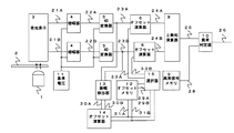
図3と図4を用いて本発明の実施例2について説明する。実施例1と異なるのは、オフセット補償部16を備えた点であり、この動作について説明する。 A second embodiment of the present invention will be described with reference to FIGS. The difference from the first embodiment is that an offset compensation unit 16 is provided, and this operation will be described.
オフセット補償部16は、オフセット補正器6、振幅検出器13、オフセット演算器14、オフセットメモリ12で構成されている。以下にそれぞれの役割について説明する。
The offset compensation unit 16 includes an offset
振幅検出器13はAD変換器5から出力されたAD変換後SIN信号23A、AD変換後COS信号23Bのそれぞれの最大値と最小値を検出する。最大値の検出は、同一方向に回転板2が回転している時にAD変換後SIN信号23AまたはAD変換後COS信号23Bの値がゼロから正の方向に増加した点から測定を開始して検出値が大きくなる毎に値を保持し、値が負になった時点で保持した値を最大値とすることで容易に検出することができる。また、最小値の検出も同様に、同一方向に回転板2が回転している時にAD変換後SIN信号23AまたはAD変換後COS信号23Bの値がゼロから負の方向に減少した点から測定を開始して検出値が小さくなる毎に値を保持し、値が正になった時点で保持した値を最小値とすることで検出することができる。
The
オフセット演算器14は振幅検出器13で検出した最大値と最小値を用いてオフセット値を演算する。オフセット値は、(最大値+最小値)とすることにより求めることができる。
The offset
オフセットメモリ12はオフセット検出器で検出したSINオフセット演算値31A、COSオフセット演算値31Bを記録するものであり、電源を遮断した場合にでも記録した値が失われないようにEEPROM等の不揮発性メモリで構成される。
The offset
オフセット補正器6はオフセットメモリ12から読み出したSINオフセットメモリ値29A、COSオフセットメモリ値29BをAD変換後SIN信号23AとAD変換後COS信号23Bから減算することによって、図4の右側に示すようにAD変換後SIN信号23AとAD変換後COS信号23Bのオフセットを補正したオフセット補正後SIN信号24A、オフセット補正後COS信号24Bを生成する。
The offset
以上の動作はエンコーダ製造時に各エンコーダ毎にオフセット演算値を求め、オフセットメモリ12に記憶する。使用する際には電源を投入する度にオフセットメモリ12からSINオフセットメモリ値29A、COSオフセットメモリ値29Bを読み出し、オフセットずれをなくしたオフセット補正後SIN信号24Aとオフセット補正後COS信号24Bを用いて発光素子1の不点灯を検出する。
In the above operation, an offset calculation value is obtained for each encoder at the time of encoder manufacture and stored in the offset
また、SINオフセット演算値31A、COSオフセット演算値31Bは使用時にも演算し、製造時に記憶した値から変動した場合にオフセットメモリ12の値を書き直すようにすることで、長時間に渡り精度よく異常を検出することができる。
In addition, the SIN offset calculation value 31A and the COS offset
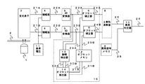
また、図5に示すようにオフセット補正は、電源投入時はオフセットメモリ12に記録した値を使用してオフセット補正を行い、使用時に新たなオフセット演算値を検出した時点で選択器15でオフセット演算に用いる値を切り替えて使用してもよい。
Further, as shown in FIG. 5, offset correction is performed by using the value recorded in the offset
以上のような構成とすることにより異常信号しきい値28を小さくして、SIN原信号21AとCOS原信号21Bを幅広い範囲で使うことができるので、発光素子1の光量が少なくなった場合にも異常が発生せず、また製造時のSIN原信号とCOS原信号のばらつき許容値を拡大し、生産性を向上させることができる。なお、本実施例においては、SINオフセット選択値33Aと、COSオフセット選択値33Bと、COS振幅値30Bと、SIN振幅値30Aと、異常判定器10とを具備している。
With the configuration as described above, the abnormal
本発明の光学式エンコーダは、90度位相差の2つの正弦波信号を用いて発光素子の異常を容易に検出することができるため、高精度の位置決め制御が必要な産業用サーボモータの光学系の保護装置として特に有効である。 The optical encoder according to the present invention can easily detect an abnormality of a light emitting element using two sine wave signals having a phase difference of 90 degrees, and therefore an optical system of an industrial servomotor that requires high-precision positioning control. It is particularly effective as a protection device.
1 発光素子
2 回転板
3 受光素子
4 増幅器
5 AD変換器
6 オフセット補正器
8 2乗和演算器
9 異常信号メモリ
10 異常判定器
11 基準電圧
12 オフセットメモリ
13 振幅検出器
14 オフセット演算器
15 選択器
16 オフセット補償部
21A SIN原信号
21B COS原信号
22A 増幅後SIN信号
22B 増幅後COS信号
23A AD変換後SIN信号
23B AD変換後COS信号
24A オフセット補正後SIN信号
24B オフセット補正後COS信号
25 2乗和信号
26 異常信号
28 異常信号しきい値
29A SINオフセットメモリ値
29B COSオフセットメモリ値
30A SIN振幅値
30B COS振幅値
31A SINオフセット演算値
31B COSオフセット演算値
33A SINオフセット選択値
33B COSオフセット選択値
DESCRIPTION OF
Claims (2)
前記90度位相差の2つの正弦波信号のそれぞれ最大値、最小値を検出する振幅検出器と、前記振幅検出器で検出した最大値と最小値から正弦波信号の中心値を演算するオフセット演算器と、前記オフセット演算器で求めた結果を記録するオフセットメモリと、前記90度位相差の2つの正弦波信号をそれぞれ2乗して加算する2乗和演算器と、
前記2つの正弦波信号のそれぞれの中心値と振幅値と位相許容とを考慮した許容すべき誤差より小さく設定した前記2つの正弦波信号の異常しきい値を記録する異常信号メモリと、前記2つの正弦波信号の異常を判定する異常判定器からなり、
前記2つの正弦波信号は前記光学式アブソリュートエンコーダの製造時または前記光学式アブソリュートエンコーダの前回電源投入時の前記オフセットメモリで記憶した中心値を用いてオフセットのずれを補正した後、前記2乗和演算器でそれぞれ2乗して加算した演算結果が、前記異常信号メモリに記録した前記異常しきい値より下回った場合に前記異常判定器が異常信号を出力して前記発光素子が不点灯である状態を判定する光学式アブソリュートエンコーダ。 A light-emitting element that emits light to the rotating plate, upper rotation data generated by dividing the slit of the rotating plate into N equal parts by one rotation, and N cycles by one rotation synchronized with the interval divided into the N equal parts 1 rotation low order data generated by performing an interpolation operation using two sine wave signals having a phase difference of 90 degrees, and the 1 rotation high order data and the 1 rotation low order data are combined to obtain 1 rotation position data. In the generated optical absolute encoder,
An amplitude detector that detects the maximum and minimum values of the two sine wave signals having a phase difference of 90 degrees, and an offset calculation that calculates the center value of the sine wave signal from the maximum and minimum values detected by the amplitude detector. An offset memory that records the results obtained by the offset calculator, and a square sum calculator that squares and adds the two sine wave signals having the phase difference of 90 degrees,
Each center value and the error signal memory for recording the anomaly threshold amplitude value and phase tolerance and the two sinusoidal signal set smaller than the error should be acceptable considering the two sine wave signals, the 2 It consists of an abnormality determiner that determines the abnormality of two sine wave signals,
The two sine wave signals are obtained by correcting the offset deviation using the center value stored in the offset memory at the time of manufacturing the optical absolute encoder or when the optical absolute encoder was last turned on, and then calculating the sum of squares. calculation result of adding by squaring respectively computing unit, the abnormality determiner has the light emitting element outputs an abnormality signal is not light when it falls below than the abnormality threshold value recorded in the abnormality signal memory Optical absolute encoder that determines the status.
An apparatus comprising the optical absolute encoder according to claim 1 .
Priority Applications (1)
| Application Number | Priority Date | Filing Date | Title |
|---|---|---|---|
| JP2011124810A JP5877323B2 (en) | 2011-06-03 | 2011-06-03 | Optical absolute encoder and device |
Applications Claiming Priority (1)
| Application Number | Priority Date | Filing Date | Title |
|---|---|---|---|
| JP2011124810A JP5877323B2 (en) | 2011-06-03 | 2011-06-03 | Optical absolute encoder and device |
Publications (2)
| Publication Number | Publication Date |
|---|---|
| JP2012251879A JP2012251879A (en) | 2012-12-20 |
| JP5877323B2 true JP5877323B2 (en) | 2016-03-08 |
Family
ID=47524822
Family Applications (1)
| Application Number | Title | Priority Date | Filing Date |
|---|---|---|---|
| JP2011124810A Active JP5877323B2 (en) | 2011-06-03 | 2011-06-03 | Optical absolute encoder and device |
Country Status (1)
| Country | Link |
|---|---|
| JP (1) | JP5877323B2 (en) |
Cited By (1)
| Publication number | Priority date | Publication date | Assignee | Title |
|---|---|---|---|---|
| CN110873582A (en) * | 2018-08-29 | 2020-03-10 | 富士电机株式会社 | Encoder, processing device and processing method |
Family Cites Families (9)
| Publication number | Priority date | Publication date | Assignee | Title |
|---|---|---|---|---|
| JPH0518783A (en) * | 1991-07-11 | 1993-01-26 | Yokogawa Electric Corp | Optical encoder |
| JPH0518785A (en) * | 1991-07-11 | 1993-01-26 | Yokogawa Electric Corp | Optical encoder |
| JPH05240664A (en) * | 1992-02-28 | 1993-09-17 | Yokogawa Electric Corp | Encoder |
| JPH10300518A (en) * | 1997-04-24 | 1998-11-13 | Canon Inc | Signal abnormality detecting circuit and displacement information detecting equipment using the same |
| JP2006284521A (en) * | 2005-04-05 | 2006-10-19 | Sendai Nikon:Kk | Encoder |
| JP4737609B2 (en) * | 2005-10-05 | 2011-08-03 | 株式会社ニコン | Encoder |
| JP4797721B2 (en) * | 2005-10-20 | 2011-10-19 | 株式会社デンソー | Rotation angle detector |
| JP5125320B2 (en) * | 2007-08-28 | 2013-01-23 | パナソニック株式会社 | Encoder correction value control method |
| JP5550213B2 (en) * | 2008-03-04 | 2014-07-16 | ハイデンハイン株式会社 | Optical absolute encoder |
-
2011
- 2011-06-03 JP JP2011124810A patent/JP5877323B2/en active Active
Cited By (2)
| Publication number | Priority date | Publication date | Assignee | Title |
|---|---|---|---|---|
| CN110873582A (en) * | 2018-08-29 | 2020-03-10 | 富士电机株式会社 | Encoder, processing device and processing method |
| CN110873582B (en) * | 2018-08-29 | 2021-10-22 | 富士电机株式会社 | Encoder, processing device and processing method |
Also Published As
| Publication number | Publication date |
|---|---|
| JP2012251879A (en) | 2012-12-20 |
Similar Documents
| Publication | Publication Date | Title |
|---|---|---|
| US7711508B2 (en) | Position detector | |
| KR102195533B1 (en) | Rotary encoder and angle correction method of rotary encoder | |
| CN102506905B (en) | A kind of High Precision Absolute Encoder | |
| CN107860404B (en) | Rotary encoder and absolute angle position detection method for rotary encoder | |
| CN108426590B (en) | Rotary encoder | |
| JP5995589B2 (en) | Correction value deriving device, displacement amount deriving device, control device, and correction value deriving method | |
| JP5402313B2 (en) | Encoder and signal processing method | |
| JP5115419B2 (en) | Optical encoder | |
| JP5877323B2 (en) | Optical absolute encoder and device | |
| JP2007218667A (en) | Offset correction circuit for encoder | |
| WO2014061380A1 (en) | Position detection unit | |
| US9134143B2 (en) | Absolute position detector with abnormality detection function | |
| JP5190644B2 (en) | Encoder error correction method | |
| JP2018132357A (en) | Rotary encoder | |
| JP2017125866A (en) | Optical encoder | |
| US11493898B2 (en) | Servo motor controller | |
| JP6182729B2 (en) | Optical encoder | |
| JP6106839B2 (en) | Encoder | |
| JP2013047693A (en) | Encoder and pattern detecting method of the same | |
| JP5341267B1 (en) | Displacement detection device and error / detection / evaluation method thereof | |
| JP4763821B2 (en) | Angle correction circuit, RD converter, and angle detection device | |
| JP5006270B2 (en) | Absolute encoder device and its operation method | |
| JP2018132359A (en) | Rotary encoder | |
| JP2006125853A (en) | Position detection system | |
| CN117040206A (en) | High-precision servo motor and electrical equipment |
Legal Events
| Date | Code | Title | Description |
|---|---|---|---|
| A621 | Written request for application examination |
Free format text: JAPANESE INTERMEDIATE CODE: A621 Effective date: 20131210 |
|
| RD01 | Notification of change of attorney |
Free format text: JAPANESE INTERMEDIATE CODE: A7421 Effective date: 20140106 |
|
| RD01 | Notification of change of attorney |
Free format text: JAPANESE INTERMEDIATE CODE: A7421 Effective date: 20140418 |
|
| A977 | Report on retrieval |
Free format text: JAPANESE INTERMEDIATE CODE: A971007 Effective date: 20140620 |
|
| A131 | Notification of reasons for refusal |
Free format text: JAPANESE INTERMEDIATE CODE: A131 Effective date: 20140708 |
|
| A521 | Written amendment |
Free format text: JAPANESE INTERMEDIATE CODE: A523 Effective date: 20140904 |
|
| A711 | Notification of change in applicant |
Free format text: JAPANESE INTERMEDIATE CODE: A711 Effective date: 20141007 |
|
| A131 | Notification of reasons for refusal |
Free format text: JAPANESE INTERMEDIATE CODE: A131 Effective date: 20150217 |
|
| A521 | Written amendment |
Free format text: JAPANESE INTERMEDIATE CODE: A523 Effective date: 20150420 |
|
| TRDD | Decision of grant or rejection written | ||
| A01 | Written decision to grant a patent or to grant a registration (utility model) |
Free format text: JAPANESE INTERMEDIATE CODE: A01 Effective date: 20150825 |
|
| A61 | First payment of annual fees (during grant procedure) |
Free format text: JAPANESE INTERMEDIATE CODE: A61 Effective date: 20150907 |
|
| R151 | Written notification of patent or utility model registration |
Ref document number: 5877323 Country of ref document: JP Free format text: JAPANESE INTERMEDIATE CODE: R151 |