JP5872913B2 - Refrigerator for railway vehicle power converter - Google Patents
Refrigerator for railway vehicle power converter Download PDFInfo
- Publication number
- JP5872913B2 JP5872913B2 JP2012009734A JP2012009734A JP5872913B2 JP 5872913 B2 JP5872913 B2 JP 5872913B2 JP 2012009734 A JP2012009734 A JP 2012009734A JP 2012009734 A JP2012009734 A JP 2012009734A JP 5872913 B2 JP5872913 B2 JP 5872913B2
- Authority
- JP
- Japan
- Prior art keywords
- heat
- cooler
- power converter
- semiconductor element
- temperature
- Prior art date
- Legal status (The legal status is an assumption and is not a legal conclusion. Google has not performed a legal analysis and makes no representation as to the accuracy of the status listed.)
- Active
Links
Images


Classifications
-
- H—ELECTRICITY
- H05—ELECTRIC TECHNIQUES NOT OTHERWISE PROVIDED FOR
- H05K—PRINTED CIRCUITS; CASINGS OR CONSTRUCTIONAL DETAILS OF ELECTRIC APPARATUS; MANUFACTURE OF ASSEMBLAGES OF ELECTRICAL COMPONENTS
- H05K7/00—Constructional details common to different types of electric apparatus
- H05K7/20—Modifications to facilitate cooling, ventilating, or heating
- H05K7/2029—Modifications to facilitate cooling, ventilating, or heating using a liquid coolant with phase change in electronic enclosures
- H05K7/20336—Heat pipes, e.g. wicks or capillary pumps
-
- A—HUMAN NECESSITIES
- A61—MEDICAL OR VETERINARY SCIENCE; HYGIENE
- A61F—FILTERS IMPLANTABLE INTO BLOOD VESSELS; PROSTHESES; DEVICES PROVIDING PATENCY TO, OR PREVENTING COLLAPSING OF, TUBULAR STRUCTURES OF THE BODY, e.g. STENTS; ORTHOPAEDIC, NURSING OR CONTRACEPTIVE DEVICES; FOMENTATION; TREATMENT OR PROTECTION OF EYES OR EARS; BANDAGES, DRESSINGS OR ABSORBENT PADS; FIRST-AID KITS
- A61F5/00—Orthopaedic methods or devices for non-surgical treatment of bones or joints; Nursing devices; Anti-rape devices
- A61F5/01—Orthopaedic devices, e.g. splints, casts or braces
- A61F5/0102—Orthopaedic devices, e.g. splints, casts or braces specially adapted for correcting deformities of the limbs or for supporting them; Ortheses, e.g. with articulations
- A61F5/0104—Orthopaedic devices, e.g. splints, casts or braces specially adapted for correcting deformities of the limbs or for supporting them; Ortheses, e.g. with articulations without articulation
- A61F5/0111—Orthopaedic devices, e.g. splints, casts or braces specially adapted for correcting deformities of the limbs or for supporting them; Ortheses, e.g. with articulations without articulation for the feet or ankles
-
- H—ELECTRICITY
- H05—ELECTRIC TECHNIQUES NOT OTHERWISE PROVIDED FOR
- H05K—PRINTED CIRCUITS; CASINGS OR CONSTRUCTIONAL DETAILS OF ELECTRIC APPARATUS; MANUFACTURE OF ASSEMBLAGES OF ELECTRICAL COMPONENTS
- H05K7/00—Constructional details common to different types of electric apparatus
- H05K7/20—Modifications to facilitate cooling, ventilating, or heating
- H05K7/2089—Modifications to facilitate cooling, ventilating, or heating for power electronics, e.g. for inverters for controlling motor
-
- A—HUMAN NECESSITIES
- A61—MEDICAL OR VETERINARY SCIENCE; HYGIENE
- A61F—FILTERS IMPLANTABLE INTO BLOOD VESSELS; PROSTHESES; DEVICES PROVIDING PATENCY TO, OR PREVENTING COLLAPSING OF, TUBULAR STRUCTURES OF THE BODY, e.g. STENTS; ORTHOPAEDIC, NURSING OR CONTRACEPTIVE DEVICES; FOMENTATION; TREATMENT OR PROTECTION OF EYES OR EARS; BANDAGES, DRESSINGS OR ABSORBENT PADS; FIRST-AID KITS
- A61F5/00—Orthopaedic methods or devices for non-surgical treatment of bones or joints; Nursing devices; Anti-rape devices
- A61F5/01—Orthopaedic devices, e.g. splints, casts or braces
- A61F5/0102—Orthopaedic devices, e.g. splints, casts or braces specially adapted for correcting deformities of the limbs or for supporting them; Ortheses, e.g. with articulations
- A61F5/0127—Orthopaedic devices, e.g. splints, casts or braces specially adapted for correcting deformities of the limbs or for supporting them; Ortheses, e.g. with articulations for the feet
-
- A—HUMAN NECESSITIES
- A61—MEDICAL OR VETERINARY SCIENCE; HYGIENE
- A61H—PHYSICAL THERAPY APPARATUS, e.g. DEVICES FOR LOCATING OR STIMULATING REFLEX POINTS IN THE BODY; ARTIFICIAL RESPIRATION; MASSAGE; BATHING DEVICES FOR SPECIAL THERAPEUTIC OR HYGIENIC PURPOSES OR SPECIFIC PARTS OF THE BODY
- A61H1/00—Apparatus for passive exercising; Vibrating apparatus ; Chiropractic devices, e.g. body impacting devices, external devices for briefly extending or aligning unbroken bones
- A61H1/02—Stretching or bending or torsioning apparatus for exercising
- A61H1/0237—Stretching or bending or torsioning apparatus for exercising for the lower limbs
- A61H1/0266—Foot
-
- H—ELECTRICITY
- H05—ELECTRIC TECHNIQUES NOT OTHERWISE PROVIDED FOR
- H05K—PRINTED CIRCUITS; CASINGS OR CONSTRUCTIONAL DETAILS OF ELECTRIC APPARATUS; MANUFACTURE OF ASSEMBLAGES OF ELECTRICAL COMPONENTS
- H05K7/00—Constructional details common to different types of electric apparatus
- H05K7/20—Modifications to facilitate cooling, ventilating, or heating
- H05K7/2089—Modifications to facilitate cooling, ventilating, or heating for power electronics, e.g. for inverters for controlling motor
- H05K7/20936—Liquid coolant with phase change
-
- A—HUMAN NECESSITIES
- A61—MEDICAL OR VETERINARY SCIENCE; HYGIENE
- A61F—FILTERS IMPLANTABLE INTO BLOOD VESSELS; PROSTHESES; DEVICES PROVIDING PATENCY TO, OR PREVENTING COLLAPSING OF, TUBULAR STRUCTURES OF THE BODY, e.g. STENTS; ORTHOPAEDIC, NURSING OR CONTRACEPTIVE DEVICES; FOMENTATION; TREATMENT OR PROTECTION OF EYES OR EARS; BANDAGES, DRESSINGS OR ABSORBENT PADS; FIRST-AID KITS
- A61F5/00—Orthopaedic methods or devices for non-surgical treatment of bones or joints; Nursing devices; Anti-rape devices
- A61F5/01—Orthopaedic devices, e.g. splints, casts or braces
- A61F5/0102—Orthopaedic devices, e.g. splints, casts or braces specially adapted for correcting deformities of the limbs or for supporting them; Ortheses, e.g. with articulations
- A61F2005/0132—Additional features of the articulation
- A61F2005/0165—Additional features of the articulation with limits of movement
- A61F2005/0167—Additional features of the articulation with limits of movement adjustable
-
- H—ELECTRICITY
- H01—ELECTRIC ELEMENTS
- H01L—SEMICONDUCTOR DEVICES NOT COVERED BY CLASS H10
- H01L2924/00—Indexing scheme for arrangements or methods for connecting or disconnecting semiconductor or solid-state bodies as covered by H01L24/00
- H01L2924/0001—Technical content checked by a classifier
- H01L2924/0002—Not covered by any one of groups H01L24/00, H01L24/00 and H01L2224/00
Description
本発明は鉄道車両に搭載された電力変換装置に関わり、特に電力変換装置に搭載される半導体素子の冷却器に関する。 The present invention relates to a power conversion device mounted on a railway vehicle, and more particularly to a semiconductor element cooler mounted on the power conversion device.
鉄道車両は商用周波数の交流電力や、直流電力を可変周波数の3相交流に変換しモーターを駆動して走行する。電力を変換する電力変換器には、例えば、パワー半導体スイッチング素子としてIGBT等の半導体素子を複数使用し、直流を可変周波数の3相交流に変換するVVVF(Variable Voltage Variable Frequency)インバータ等が広く使われている。
IGBT等の半導体素子は電力変換の際に大きな損失を生じるため、専用の冷却器が必要となる。この冷却器は放熱のために多数の放熱フィンを有し、ファンにより放熱フィンに冷却風を送風して冷却したり、あるいは、放熱フィンを車体側面に露出させて走行時に車体側面を流れる走行風を放熱フィンに当てることで冷却を行っている。
このように車両走行時に車体側面を流れる空気により冷却する方式を採用した冷却器を走行風冷却器と呼ぶ。
Railway vehicles travel by driving commercial motors by converting commercial frequency AC power or DC power into variable frequency three-phase AC. For power converters that convert power, for example, a VVVF (Variable Voltage Variable Frequency) inverter that uses a plurality of semiconductor elements such as IGBTs as power semiconductor switching elements and converts direct current into three-phase alternating current of variable frequency is widely used. It has been broken.
Since semiconductor elements such as IGBT cause a large loss during power conversion, a dedicated cooler is required. This cooler has many radiating fins for radiating heat, and it is cooled by blowing cooling air to the radiating fins with a fan, or the radiating fins are exposed on the side of the vehicle body and run on the side of the vehicle body when traveling Cooling is performed by hitting to the heat radiation fin.
A cooler that employs a method of cooling with air flowing on the side surface of the vehicle body when the vehicle is traveling is called a traveling wind cooler.
走行風冷却器では、ファンを設ける必要はなく、低コストであるが、走行風は車速により風速が変化し、車速が増加すると冷却風速も大きくなって、冷却性能も向上するが、停車時、低速走行時には、走行風による冷却風速が小さくなるため冷却性能が低下し、特に停車時が冷却性能は最も低くなる。このため、走行風冷却の冷却器は、停車時においても、すべての半導体素子を十分に冷却できるように設計されている。
停車時に冷却器に流れる冷却風は、放熱フィンからの熱放散による上昇気流により発生し、電力変換器下部から取り込まれた上昇気流が下部の半導体素子を冷却し、続いて上部の半導体素子を冷却して電力変換器上部へ抜ける。
In the running wind cooler, it is not necessary to provide a fan and the cost is low.However, the running wind changes depending on the vehicle speed, and if the vehicle speed increases, the cooling wind speed increases and the cooling performance improves. When traveling at a low speed, the cooling performance is lowered because the cooling wind speed by the traveling wind is reduced, and the cooling performance is lowest when the vehicle is stopped. For this reason, the cooler for running wind cooling is designed to sufficiently cool all the semiconductor elements even when the vehicle is stopped.
Cooling air that flows to the cooler when the vehicle is stopped is generated by the rising airflow due to heat dissipation from the heat radiating fins, and the rising airflow taken from the lower part of the power converter cools the lower semiconductor element, and then cools the upper semiconductor element. Then go to the top of the power converter.
電力変換器下部の半導体素子は、冷却器下部から取り入れられた温度の低い外気により冷却されるが、電力変換器上部の半導体素子は、下部の半導体素子により加熱された上昇気流により冷却されるために、十分な放熱が行えず、結果的に冷却性能が低下する。このため、一般には電力変換器上部の半導体素子を冷却する冷却器の放熱性能が高くなるよう、例えば放熱フィンの枚数を増やしたり、ヒートパイプ等の熱輸送用の伝熱管の本数を増やすなどの対策がとられている。 The semiconductor element at the lower part of the power converter is cooled by the low temperature outside air taken from the lower part of the cooler, but the semiconductor element at the upper part of the power converter is cooled by the updraft heated by the lower semiconductor element. In addition, sufficient heat dissipation cannot be performed, and as a result, the cooling performance decreases. For this reason, in general, for example, the number of radiating fins is increased or the number of heat transfer tubes for heat transport such as heat pipes is increased so that the heat dissipation performance of the cooler that cools the semiconductor element above the power converter is increased. Measures are taken.
以下、図6〜図10により、従来技術を説明する。
図6は従来の走行風冷却器の斜視図、図7は図6の横面図、図8は上面図である。また図9は従来の走行風冷却器の性能曲線を示す。
Hereinafter, the prior art will be described with reference to FIGS.
6 is a perspective view of a conventional traveling wind cooler, FIG. 7 is a lateral view of FIG. 6, and FIG. 8 is a top view. FIG. 9 shows a performance curve of a conventional traveling wind cooler.
図6において、600は鉄道車両の進行方向に対し略平行かつ垂直に配置された吸熱板、601は吸熱板600に略平行に配列された放熱フィン、602は吸熱板600に取り付けられたサーミスタ等の温度検出素子、603は吸熱板600の一方の面に熱交換可能に接触するよう設置されたIGBTなどの電力変換器を構成する半導体素子、604は半導体素子603の設置面に対向するよう吸熱板600の他方の面から吸熱板600に対し略垂直方向に延びるよう配置された伝熱管を示す。なお、この例では、半導体素子603は、鉄道車両の進行方向に3列、各列毎に上下2段に設けられ、温度検出素子602は、各列の上部の半導体素子603の温度を検出するよう吸熱板600に取り付けられている。
In FIG. 6,
半導体素子603で発生した熱は、吸熱板600に吸収され、その熱は、吸熱板600に一部が埋設、あるいは接触されている伝熱管604に伝えられる。伝熱管604としては、内部に規定量の液状の冷媒、例えば水等を入れ、その冷媒の相変化により伝熱する所謂ヒートパイプ式等が使用される。
伝熱管604の熱は放熱フィン601に伝わり、空気中に放熱されるが、放熱フィン601により、効率的に伝熱管604からの熱を空気に伝えるよう、一般的には複数枚設けられる。
The heat generated in the
The heat of the
近年鉄道車両に対しても、省エネルギーの観点から、各機器の軽量小型化と低コスト化が強く求められており、こうした走行風冷却器についても設計上、放熱フィン601や伝熱管604を必要最小限にすることが重要な課題となっている。しかも前述したように、走行風冷却器では、低速あるいは停車時に電力変換器上部の半導体素子を冷却する冷却器の冷却性能が低下するという問題があるため、電力変換器上部に限定して冷却を強化する構成がとられており、例えば、図6〜8に示されるように、電力変換器上部の放熱フィン601の枚数や伝熱管604の本数を、電力変換器下部と比較して多くして冷却性能を高めるよう設計されている。
In recent years, there has been a strong demand for reducing the weight and cost of each device from the viewpoint of energy saving for railway vehicles, and the design of such a traveling wind cooler is also the minimum required for
図9は、図6〜8のように電力変換器上部の冷却を強化した場合の効果を説明する性能図である。図9は車速と冷却性能の関係を示しており、冷却性能はグラフ上方に行くほど高くなる。図中の実線は電力変換器下部の冷却器による冷却性能を、点線は電力変換器上部と電力変換器下部の冷却性能を同等とした場合、すなわち、放熱フィン601の枚数や、伝熱管の本数を上下均一にした際の電力変換器上部の冷却性能を、一点鎖線は電力変換器上部の放熱フィン601の枚数や、伝熱管604の本数を増やすことにより、電力変換器上部の冷却器による冷却性能を向上させた場合の性能をそれぞれ示す。
上下で冷却性能を均一にした場合(図9の一点鎖線)は、停車もしくは低速時には、十分な走行風が得られず、しかも上段の冷却器は下段の冷却器により加熱された上昇気流の影響を受け、冷却性能が著しく低くなるが、車速が上がると冷却性能は向上し、やがて設計上の最高速度近辺で飽和傾向を示す。
FIG. 9 is a performance diagram for explaining the effect when the cooling of the upper portion of the power converter is enhanced as in FIGS. FIG. 9 shows the relationship between the vehicle speed and the cooling performance, and the cooling performance increases as it goes upward in the graph. In the figure, the solid line indicates the cooling performance of the cooler at the lower part of the power converter, and the dotted line indicates the cooling performance of the upper part of the power converter and the lower part of the power converter, that is, the number of radiating
When the cooling performance is made uniform at the top and bottom (the one-dot chain line in FIG. 9), sufficient running wind cannot be obtained when the vehicle is stopped or at low speed, and the upper cooler is affected by the rising airflow heated by the lower cooler. As a result, the cooling performance is significantly reduced, but the cooling performance improves as the vehicle speed increases, and eventually shows a saturation tendency near the maximum design speed.
一方、例えば、電力変換器上部の放熱フィンの枚数を増やした場合(図9の点線)には、全体的に性能が向上し、特に停車もしくは低速時の冷却性能が大幅に改善され、下段の冷却器の性能に近づいており、車速が増加するにつれ冷却性能は増加してゆき、設計上の最高速度で、下段の冷却性能を飽和させ、上段の冷却性能が下段の冷却性能と同等になるよう設計されている。このように設計することにより、放熱フィンの枚数や伝熱管の本数、さらには冷却器の体積を最小限にできるとともに、コストを低減できることが知られている。 On the other hand, for example, when the number of radiating fins in the upper part of the power converter is increased (dotted line in FIG. 9), the overall performance is improved, and particularly the cooling performance at the time of stopping or low speed is greatly improved. As the vehicle speed increases, the cooling performance increases as the vehicle speed increases, saturates the lower cooling performance at the maximum design speed, and the upper cooling performance becomes equivalent to the lower cooling performance. It is designed as follows. By designing in this way, it is known that the number of radiating fins, the number of heat transfer tubes, the volume of the cooler can be minimized, and the cost can be reduced.
このような冷却器に対しては、半導体素子603の異常過熱による破壊を防止するために、図6に示されるように、設計上の最高速度まで、常に下段の冷却器の冷却性能を下回り、最高温度に達する可能性が高い、上段の風上側、中央部、風下側にそれぞれ温度検知素子602を取り付けている。
例えば下記の特許文献1にこの構造が開示されている。
For such a cooler, in order to prevent destruction due to abnormal overheating of the
For example, Patent Document 1 below discloses this structure.
しかしながら上述の冷却器には以下に述べる問題点がある。
すなわち、前述したように、走行風冷却器では停車時、もしくは低速時に電力変換器上段の冷却を強化し、設計上の最高速度で電力変換器の上部と下部で冷却性能が同等となるよう設計されている。
これは、設計上の車両最高速度を所定速度とした電力変換器の場合は問題ないが、特に近年では、車両コストを上昇させることなく、すなわち大きな設計変更を伴うことなくより最高速度を高めることが求められていることから、半導体素子、放熱フィンや伝熱管の配置など、走行風冷却器の基本仕様を変更することなく、より高速走行を可能にすることが求められている。
However, the above-described cooler has the following problems.
In other words, as described above, the running wind cooler enhances the cooling of the upper stage of the power converter when the vehicle is stopped or at a low speed, and the cooling performance is designed to be the same at the upper and lower parts of the power converter at the maximum design speed. Has been.
This is not a problem for power converters with a design maximum vehicle speed of a specified speed, but in particular, in recent years, it is possible to increase the maximum speed without increasing the vehicle cost, i.e. without major design changes. Therefore, it is required to enable higher speed travel without changing the basic specifications of the travel wind cooler, such as the arrangement of semiconductor elements, radiation fins and heat transfer tubes.
また、鉄道車両が設計上の最高速度以下で走行している場合でも、鉄道車両が向かい風を受けた場合、走行風冷却器が受ける冷却風は、相対的に設計上の最高速度より高い速度で走行した場合の走行風と同じ速度になる。
このような場合、設計上の最高速度を超えるにつれ、下部の冷却性能が上部の冷却性能より低くなる場合が生じることがわかった。
Even when the railway vehicle is traveling below the maximum design speed, if the railway vehicle receives a headwind, the cooling wind received by the traveling wind cooler is relatively higher than the maximum design speed. It becomes the same speed as the running wind when running.
In such a case, it has been found that as the maximum design speed is exceeded, the lower cooling performance may become lower than the upper cooling performance.
例えば、図10に示すように、設計上の最高速度を高めたり、向かい風によって一定の加算分が加わると、冷却風の風速が相対的に設計最高速度より高くなるが、電力変換器下段の冷却器の冷却性能は飽和しているのに対し、放熱フィンを増加させた電力変換器上段の冷却器の冷却性能が上昇し、設計上の最高速度付近で、電力変換器上段の冷却器と下段の冷却器の性能線が交差し、加算される速度が増えるにつれ、下段の冷却器の冷却性能が、上段の冷却器の冷却性能を下回ってしまう。
これは、そもそも下段の冷却器は上段の冷却器より冷却性能が低く設計されており、しかも、冷却風の速度が、相対的に設計上の車両速度を超えたため、下方の半導体素子により加熱された上昇気流が、高速の冷却風により上方の冷却器に到ることなく、冷却風に沿って流れることによるものと推測される。
このことは、特に、冷却風の上流側にある半導体素子からの放熱の影響を受ける、下段風下側の冷却器において特に顕著である。
For example, as shown in FIG. 10, when the maximum design speed is increased or when a certain amount of addition is added by the head wind, the cooling wind speed is relatively higher than the design maximum speed, but the cooling of the lower stage of the power converter Although the cooling performance of the power converter is saturated, the cooling performance of the upper cooler of the power converter with increased radiating fins increases, and the upper cooler and lower cooler of the power converter are near the maximum design speed. As the performance line of the second cooler crosses and the rate of addition increases, the cooling performance of the lower cooler falls below the cooling performance of the upper cooler.
This is because the lower cooler is designed to have lower cooling performance than the upper cooler, and the cooling air speed is relatively higher than the designed vehicle speed, so it is heated by the lower semiconductor element. It is presumed that the rising airflow is caused to flow along the cooling air without reaching the upper cooler by the high-speed cooling air.
This is particularly conspicuous in the cooler on the lower leeward side, which is affected by heat radiation from the semiconductor element upstream of the cooling air.
このような状況下で車両が走行を継続すると、下段風下側の半導体素子が他の半導体素子に比べて最も過熱する可能性が高いにもかかわらず、従来のように、電力変換器上段にのみサーミスタを設けた場合には、電力変換器下段風下側の半導体素子異常を検知できないという問題があった。また、この防止のために上段、下段のいずれの半導体素子にもサーミスタを付けると、サーミスタ接続用の配線の数が増大し装置が複雑になり、コスト上昇を招くという問題があった。
本発明はこの課題を解決するものであって、設計上の最高速度を高めたり、向かい風等外部環境の影響下でも、基本設計を変更することなく、停車から最高速まで安定して異常検知を行えるようにした冷却器を提供することを目的とする。
If the vehicle continues to run under such conditions, the semiconductor element on the leeward side of the lower tier is most likely to overheat compared to other semiconductor elements. When the thermistor is provided, there is a problem that an abnormality of the semiconductor element on the lee side of the power converter lower stage cannot be detected. In addition, if a thermistor is attached to both the upper and lower semiconductor elements to prevent this, there is a problem that the number of wirings for connecting the thermistor increases, the apparatus becomes complicated, and the cost increases.
The present invention solves this problem, and it can stably detect anomalies from stopping to maximum speed without changing the basic design even under the influence of the external environment such as headwinds or increasing the maximum design speed. An object of the present invention is to provide a cooler that can be used.
上記の目的を達成するため、本発明の鉄道車両用電力変換装置の冷却器は、次のような技術的手段を講じた。すなわち、
(1)鉄道車両の進行方向に略平行かつ垂直に配置された吸熱板と、該吸熱板の一方の面に接触するよう設置されるとともに、鉄道車両の進行方向に沿って複数列、上下方向に複数段配列された複数の半導体素子と、該半導体素子の設置面に対向するよう、前記吸熱板の他方の面に一部が埋設あるいは接触され、前記吸熱板に対して略垂直に配置された伝熱管と、該伝熱管の他部に接触し、前記吸熱板に略平行に複数設けられた放熱フィンと、前記吸熱板の一方の面に配置され、前記半導体素子の温度を検出する複数の温度検出素子とを有する鉄道車両用電力変換装置用の冷却器において、前記伝熱管あるいは前記放熱フィンは、各列の前記半導体素子のうち、上段に配置された半導体素子の冷却性能を高めるように配置されており、かつ、前記複数の温度検出素子を、前記放熱フィンと熱交換を行う走行風からみて、風上側及び風下側については上段の半導体素子の温度は検出せず下段の半導体素子の温度を検出し、中央部については下段の半導体素子の温度は検出せず上段の半導体素子の温度を検出するように配置した。
In order to achieve the above object, the cooler for a railway vehicle power converter according to the present invention employs the following technical means. That is,
(1) An endothermic plate disposed substantially parallel and perpendicular to the traveling direction of the railway vehicle, and installed in contact with one surface of the endothermic plate, and in a plurality of rows along the traveling direction of the railcar, in the vertical direction A plurality of semiconductor elements arranged in a plurality of stages, and a part of the endothermic plate is embedded or contacted so as to face the installation surface of the semiconductor element, and is disposed substantially perpendicular to the endothermic plate. A plurality of heat-dissipating tubes, a plurality of heat dissipating fins that are in contact with the other part of the heat-conducting tube and substantially parallel to the heat-absorbing plate, and a plurality of heat-dissipating tubes that are disposed on one surface of the heat-absorbing plate and detect the temperature of the semiconductor element in the cooler for power converter system for a railway vehicle and a temperature detecting element, the heat transfer tubes or the heat radiating fins, among the semiconductor elements in each column, so as to enhance the cooling performance of the semiconductor elements arranged in the upper And, and A serial plurality of temperature sensing element, said viewed from radiating fins and running wind that performs heat exchange, detects the temperature of the lower semiconductor element without detecting the temperature of the upper semiconductor element for windward side and the leeward side, the central portion With respect to, the temperature of the lower semiconductor element was not detected, and the temperature of the upper semiconductor element was detected.
(2)上記の鉄道車両用電力変換装置の冷却器において、前記複数の温度検出素子を、中段においては、前記中央部の上段に配置された温度検出素子より低く、かつ風下側及び風上側の下段に配置された温度検出素子より高い位置となるよう配置した。 (2) in the cooler of the above railway vehicle power conversion device, a plurality of temperature sensing elements, in the middle, below the temperature sensing element disposed in the upper part of the central portion, and on the leeward side and the windward side It arrange | positioned so that it might become a position higher than the temperature detection element arrange | positioned in the lower stage.
(3)上記の鉄道車両用電力変換装置の冷却器において、前記半導体素子をIGBTとした。 (3) In the cooler of the above railway vehicle power converter, the semiconductor element is an IGBT.
(4)上記の鉄道車両用電力変換装置の冷却器において、前記温度検出素子をサーミスタとした。 (4) In the cooler for a railway vehicle power converter, the temperature detection element is a thermistor.
本発明によれば、冷却器等の仕様を変えず設計上の最高速度を高めたり、向かい風等想定外の環境の影響を受けた場合でも、温度検出素子を追加することなく、最も過熱する可能性の高い半導体素子の温度を確実に検出することが可能となり、コストアップを招くことなく安全性の高い鉄道車両用電力変換装置用冷却器を実現することができる。 According to the present invention, even when the design maximum speed is increased without changing the specifications of the cooler, etc., or even under the influence of an unexpected environment such as a head wind, it is possible to overheat most without adding a temperature detection element. Therefore, it is possible to reliably detect the temperature of a highly reliable semiconductor element, and it is possible to realize a highly safe railcar power converter cooler without causing an increase in cost.
以下、図面に基づいて実施例を説明する。 Embodiments will be described below with reference to the drawings.
[実施例1]
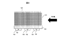
図1は本発明の実施例1の鉄道車両用電力変換装置の冷却器を示す鳥瞰図、図2は図1の側面図、図3は図1の上面図である。
図1〜3において、100は吸熱板、101は放熱フィン、102は温度検出素子、103は半導体素子、104は伝熱管であり、温度検出素子102の配置を除き、図6〜図8の従来技術と基本構造は同様である。
[Example 1]
1 is a bird's-eye view showing a cooler of a railway vehicle power converter according to a first embodiment of the present invention, FIG. 2 is a side view of FIG. 1, and FIG. 3 is a top view of FIG.
1-3, 100 is a heat absorbing plate, 101 is a heat radiating fin, 102 is a temperature detecting element, 103 is a semiconductor element, 104 is a heat transfer tube, and the conventional arrangement of FIGS. The technology and basic structure are the same.
本実施例の特徴は、温度検出素子102を、図1において矢印方向の冷却風、すなわち走行風からみて、風上側と風下側については下段に、中央部については上段に設けた点にある。
図4において、実線は電力変換器上段中央部の冷却性能の特性を、点線は下段風下側の冷却性能の特性を、一点鎖線は下段風上側の冷却性能の特性を表す。
上段中央部に配置された冷却器は、その風上側、風下側及び下部を他の冷却器に囲まれているため、上段風上側に配置された冷却器はもとより、上段風下側に配置された冷却より冷却性能が低下し、停止から設計上の最高速度に到るまでは、他の箇所の冷却器と比較して冷却性能が最も悪化する。そこで、電力変換器の上段については、中央部にのみ温度検出素子102を設ければ、過熱する可能性が最も高い半導体素子温度を確実に検出することができる。
The feature of this embodiment is that the
In FIG. 4, the solid line represents the cooling performance characteristic of the upper middle portion of the power converter, the dotted line represents the cooling performance characteristic of the lower leeward side, and the alternate long and short dash line represents the cooling performance characteristic of the lower leeward upper side.
The cooler placed in the upper central part is surrounded by other coolers on the windward side, leeward side and lower part, so it was placed on the upper windward side as well as the cooler placed on the upper windward side. The cooling performance is lower than that of the cooling, and the cooling performance is most deteriorated as compared with the coolers in other places until the maximum speed on the design is reached after stopping. Therefore, if the
一方、設計上の最高速度に加算分が加わったときは、図4からも明らかなように、下段風下側の冷却性能が、上段中央部に配置された冷却器の冷却性能を下回り、過熱する可能性が最も高くなる。
これは、下段の冷却器については、そもそも上段の冷却器と比較して冷却性能が低く設定されており、この速度領域では、特に、風下側の冷却器では、風上側の冷却器から放出された熱が走行風で運ばれ、その影響を強く受けるためである。
このため、電力変換器の風上側と風下側については、温度検出素子102を下段に設ければ、設計上の最高速度を超えた速度域において、過熱する可能性が最も高くなる半導体素子温度を確実に検出することができる。
On the other hand, when an additional amount is added to the design maximum speed, as is apparent from FIG. 4, the cooling performance on the lower leeward side is lower than the cooling performance of the cooler disposed in the upper central portion and overheats. Most likely.
This is because the cooling performance of the lower cooler is set lower than that of the upper cooler in the first place. In this speed range, the cooler on the leeward side is discharged from the cooler on the upper windward side. This is because the heat is carried by the driving wind and is strongly influenced by it.
Therefore, for the windward side and the leeward side of the power converter, by providing the
なお、鉄道車両は一般に、折り返し運転などにより走行方向を反転しながら運用されることが多く、片側だけに付けた場合には折り返し運転時には風上側になってしまい、所望の効果を得られない。このため電力変換器の下段については、左右両端の半導体素子温度を検出するよう配置する必要がある。その場合でも、図6に示されるような従来技術と比較して、使用する温度検出素子102の数を同じにすることができる。
In general, a railway vehicle is often operated while reversing the traveling direction by a turn-back operation or the like, and if it is attached to only one side, it becomes the windward side during the turn-back operation, and a desired effect cannot be obtained. For this reason, it is necessary to arrange | position the lower stage of a power converter so that the semiconductor element temperature of both right and left ends may be detected. Even in that case, the number of
本実施例の構成によれば、冷却器の仕様を等まったく変更せず、設計上の最高速度を高めた場合や、向かい風などの外部条件が設計の想定外に変化しても、サーミスタの数を増加させることなく、停車状態から設計上の最高速度を超える高速域に到るまで、過熱する可能性が最も高い半導体素子の温度を確実に検出することが可能となる。 According to the configuration of the present embodiment, the number of thermistors is not changed even if the specification of the cooler is changed at all, even when the maximum design speed is increased, or even if external conditions such as headwind change outside the design. Without increasing the temperature, it is possible to reliably detect the temperature of the semiconductor element that is most likely to be overheated until the vehicle reaches a high speed range that exceeds the designed maximum speed.
[実施例2]
図5に本発明の実施例2の全体構造を示す。
図5において、500は吸熱板、501は放熱フィン、502は温度検出素子、503は半導体素子である。
本実施例の特徴は、上下方向に3段以上の半導体素子が配列された場合、温度検出素子502の設置位置を、下部の左右端部だけでなく、中央部にも配置した点にある。
図5に示す電力変換器では、半導体素子503を上下方向に3段配置し、鉄道車両の進行方向に5列以上配置する例を示している。
[Example 2]
FIG. 5 shows the overall structure of the second embodiment of the present invention.
In FIG. 5, 500 is a heat absorbing plate, 501 is a radiation fin, 502 is a temperature detecting element, and 503 is a semiconductor element.
The feature of this embodiment is that, when three or more stages of semiconductor elements are arranged in the vertical direction, the installation position of the
In the power converter shown in FIG. 5, an example is shown in which
この構成の場合、低速時から最高速に至るまでの間の区間では、中段においては、風下側と風上側を除き、上下左右の四方が他の冷却器に囲まれているため、設計上の最高速度に加算分が加わったときは、中段中央部付近にある冷却器の性能が最も低くなる場合が発生する。このため、本実施例では、電力変換器の中段に配置される半導体素子503については、中央部付近に温度検出素子502を取り付けることにより、過熱する可能性が最も高い半導体素子の温度を確実に検知できるようにしている。
In the case of this configuration, in the section from the low speed to the maximum speed, in the middle stage, except for the leeward side and the windward side, the upper, lower, left and right sides are surrounded by other coolers. When an additional amount is added to the maximum speed, the cooler near the center of the middle stage may have the lowest performance. For this reason, in this embodiment, for the
100:吸熱板、101:放熱フィン、102:温度検出素子、103:半導体素子、104:伝熱管、500:吸熱板、501:放熱フィン、502:温度検出素子、503:半導体素子、600:吸熱板、601:放熱フィン、602:温度検出素子、603:半導体素子、604:伝熱管 100: endothermic plate, 101: radiating fin, 102: temperature detecting element, 103: semiconductor element, 104: heat transfer tube, 500: endothermic plate, 501: radiating fin, 502: temperature detecting element, 503: semiconductor element, 600: endothermic Plate, 601: Radiation fin, 602: Temperature detection element, 603: Semiconductor element, 604: Heat transfer tube
Claims (4)
前記伝熱管あるいは前記放熱フィンは、各列の前記半導体素子のうち、上段に配置された半導体素子の冷却性能を高めるように配置されており、かつ、前記複数の温度検出素子を、前記放熱フィンと熱交換を行う走行風からみて、風上側及び風下側については上段の半導体素子の温度は検出せず下段の半導体素子の温度を検出し、中央部については下段の半導体素子の温度は検出せず上段の半導体素子の温度を検出するように配置したことを特徴とする鉄道車両用電力変換装置の冷却器。 An endothermic plate disposed substantially parallel and perpendicular to the traveling direction of the railway vehicle, and installed in contact with one surface of the endothermic plate, and in a plurality of rows along the traveling direction of the railcar and in a plurality of stages in the vertical direction A plurality of semiconductor elements arranged and a part of the heat-absorbing plate that is partly embedded in or contacted with the other surface of the heat-absorbing plate so as to face the installation surface of the semiconductor element, and is disposed substantially perpendicular to the heat-absorbing plate. A heat tube, a plurality of heat dissipating fins that are in contact with the other part of the heat transfer tube and substantially parallel to the heat absorbing plate, and a plurality of temperatures that are disposed on one surface of the heat absorbing plate and detect the temperature of the semiconductor element In a cooler for a railway vehicle power converter having a detection element,
The heat transfer pipe or the heat radiating fins, among the semiconductor elements in each column are arranged so as to enhance the cooling performance of the semiconductor elements arranged in the upper and the plurality of temperature detection elements, the radiating fins and viewed from the traveling wind performing heat exchange, the temperature of the upper semiconductor element for windward side and the leeward side detects the temperature of the lower semiconductor element without detecting the temperature of the lower semiconductor element for a central portion not detect condenser of the power converter system for a railway vehicle, characterized in that arranged to detect the temperature of the upper semiconductor element without.
Priority Applications (5)
| Application Number | Priority Date | Filing Date | Title |
|---|---|---|---|
| JP2012009734A JP5872913B2 (en) | 2012-01-20 | 2012-01-20 | Refrigerator for railway vehicle power converter |
| CN201310011803.2A CN103219869B (en) | 2012-01-20 | 2013-01-11 | The cooler of power converter for railway rolling stock |
| KR1020130005463A KR101449828B1 (en) | 2012-01-20 | 2013-01-17 | Cooler of power converter for railway vehicle |
| US13/743,370 US8908375B2 (en) | 2012-01-20 | 2013-01-17 | Cooler of power converting device for railroad vehicle |
| EP13151823.5A EP2618646B1 (en) | 2012-01-20 | 2013-01-18 | Cooler of power converting device for railroad vehicle |
Applications Claiming Priority (1)
| Application Number | Priority Date | Filing Date | Title |
|---|---|---|---|
| JP2012009734A JP5872913B2 (en) | 2012-01-20 | 2012-01-20 | Refrigerator for railway vehicle power converter |
Publications (3)
| Publication Number | Publication Date |
|---|---|
| JP2013149818A JP2013149818A (en) | 2013-08-01 |
| JP2013149818A5 JP2013149818A5 (en) | 2014-05-01 |
| JP5872913B2 true JP5872913B2 (en) | 2016-03-01 |
Family
ID=47713842
Family Applications (1)
| Application Number | Title | Priority Date | Filing Date |
|---|---|---|---|
| JP2012009734A Active JP5872913B2 (en) | 2012-01-20 | 2012-01-20 | Refrigerator for railway vehicle power converter |
Country Status (5)
| Country | Link |
|---|---|
| US (1) | US8908375B2 (en) |
| EP (1) | EP2618646B1 (en) |
| JP (1) | JP5872913B2 (en) |
| KR (1) | KR101449828B1 (en) |
| CN (1) | CN103219869B (en) |
Families Citing this family (9)
| Publication number | Priority date | Publication date | Assignee | Title |
|---|---|---|---|---|
| CN103167780B (en) * | 2011-12-16 | 2016-06-08 | 台达电子企业管理(上海)有限公司 | Power model combined radiator assembly |
| JP2015050257A (en) * | 2013-08-30 | 2015-03-16 | 株式会社東芝 | Power conversion device for vehicle and railway vehicle |
| JP6135546B2 (en) * | 2014-02-25 | 2017-05-31 | 株式会社デンソー | Power converter |
| JP2016163535A (en) * | 2015-03-05 | 2016-09-05 | トヨタ自動車株式会社 | Semiconductor module |
| JP2016178208A (en) * | 2015-03-20 | 2016-10-06 | 日本電気株式会社 | Heat sink, heat dissipation structure, cooling structure and device |
| KR20160139094A (en) * | 2015-05-26 | 2016-12-07 | 엘에스산전 주식회사 | Closed cabinet for electric device having heat pipe |
| KR101922991B1 (en) * | 2016-12-23 | 2018-11-28 | 효성중공업 주식회사 | Power device cooling device for power conversion device |
| CN114071966A (en) | 2017-05-18 | 2022-02-18 | 北京嘉楠捷思信息技术有限公司 | Circuit board, radiator, working assembly and electronic equipment |
| CN109936296A (en) * | 2017-12-15 | 2019-06-25 | 株洲中车时代电气股份有限公司 | A kind of train and current transformer cooling system |
Family Cites Families (16)
| Publication number | Priority date | Publication date | Assignee | Title |
|---|---|---|---|---|
| JPS60116153A (en) * | 1983-11-28 | 1985-06-22 | Nec Corp | Integrated circuit package structure |
| JPH05102352A (en) * | 1991-10-11 | 1993-04-23 | Mitsubishi Electric Corp | Cooler for semiconductor power module |
| JP2000161880A (en) * | 1998-11-26 | 2000-06-16 | Toshiba Corp | Heat pipe type cooler |
| JP2000200866A (en) * | 1999-01-07 | 2000-07-18 | Hitachi Ltd | Semiconductor cooling device for vehicle controller |
| JP4098534B2 (en) * | 2002-02-28 | 2008-06-11 | 三菱電機株式会社 | Mobile cooling system |
| JP2004186702A (en) * | 2004-01-19 | 2004-07-02 | Toshiba Transport Eng Inc | Cooling device for power converter |
| TW200530566A (en) * | 2004-03-05 | 2005-09-16 | Hitachi Ind Equipment Sys | Method for detecting temperature of semiconductor element and semiconductor power converter |
| JP4366269B2 (en) * | 2004-07-30 | 2009-11-18 | 株式会社日立産機システム | Semiconductor element temperature detection method and power conversion device |
| JP2005252090A (en) * | 2004-03-05 | 2005-09-15 | Hitachi Industrial Equipment Systems Co Ltd | Method for detecting temperature of semiconductor element and semiconductor power converter |
| JP4202999B2 (en) * | 2004-10-22 | 2008-12-24 | 株式会社東芝 | Power supply for vehicle |
| JP4836481B2 (en) * | 2005-04-13 | 2011-12-14 | 株式会社東芝 | Semiconductor cooling device for vehicle |
| JP4756202B2 (en) * | 2005-11-10 | 2011-08-24 | 富士電機株式会社 | Railway vehicle power converter |
| JP2008218536A (en) * | 2007-03-01 | 2008-09-18 | Hitachi Ltd | Semiconductor cooling device for car controller |
| EP1990830A1 (en) * | 2007-04-12 | 2008-11-12 | Siemens Aktiengesellschaft | Semi-conductor module |
| JP4929325B2 (en) * | 2009-08-27 | 2012-05-09 | 株式会社日立製作所 | Power converter |
| JP5401419B2 (en) * | 2010-08-31 | 2014-01-29 | 株式会社日立製作所 | Railway vehicle power converter |
-
2012
- 2012-01-20 JP JP2012009734A patent/JP5872913B2/en active Active
-
2013
- 2013-01-11 CN CN201310011803.2A patent/CN103219869B/en active Active
- 2013-01-17 KR KR1020130005463A patent/KR101449828B1/en active IP Right Grant
- 2013-01-17 US US13/743,370 patent/US8908375B2/en active Active
- 2013-01-18 EP EP13151823.5A patent/EP2618646B1/en active Active
Also Published As
| Publication number | Publication date |
|---|---|
| CN103219869B (en) | 2016-12-28 |
| KR20130085981A (en) | 2013-07-30 |
| EP2618646B1 (en) | 2018-07-11 |
| EP2618646A2 (en) | 2013-07-24 |
| KR101449828B1 (en) | 2014-10-08 |
| JP2013149818A (en) | 2013-08-01 |
| US8908375B2 (en) | 2014-12-09 |
| EP2618646A3 (en) | 2017-01-25 |
| CN103219869A (en) | 2013-07-24 |
| US20130188315A1 (en) | 2013-07-25 |
Similar Documents
| Publication | Publication Date | Title |
|---|---|---|
| JP5872913B2 (en) | Refrigerator for railway vehicle power converter | |
| JP5401419B2 (en) | Railway vehicle power converter | |
| EP2469996A2 (en) | Cooling device and power conversion device including the same | |
| CA2688583C (en) | Electric power converting apparatus | |
| JP5581119B2 (en) | Cooling device, power converter, railway vehicle | |
| JP5941741B2 (en) | Power converter | |
| JP4912512B1 (en) | Cooling device and power conversion device | |
| JP2013149818A5 (en) | ||
| CN104283405B (en) | Traction converter and railway vehicle | |
| CN108766946B (en) | Liquid cooling heat abstractor and motor controller | |
| JP3621298B2 (en) | Cooling device for power converter | |
| KR101914927B1 (en) | cooling module for Insulated Gate Bipolar Transistors | |
| US8860213B2 (en) | Power converter | |
| JP2004186702A (en) | Cooling device for power converter | |
| JP6300363B2 (en) | Power converter | |
| JP2014055702A (en) | Power conversion device and railway vehicle mounted with the same | |
| JP5875995B2 (en) | Driving device for railway vehicles | |
| JP5606494B2 (en) | Railway vehicle power converter | |
| JP2016078654A (en) | Electric power conversion system and railway vehicle mounted with the same | |
| JP2014082819A (en) | Power converter and cooling medium freezing detection method | |
| JP2015156411A (en) | Power converter and railway vehicle mounting the same | |
| JP2017069356A (en) | Electric power conversion device and railway vehicle equipped with the same | |
| CN111595101A (en) | Air-cooled circulating drinking liquid semiconductor refrigeration system and refrigeration equipment | |
| JP2014008808A (en) | Electric vehicle system | |
| JP2012201138A (en) | Forced air cooling type semiconductor cooling device |
Legal Events
| Date | Code | Title | Description |
|---|---|---|---|
| A521 | Request for written amendment filed |
Free format text: JAPANESE INTERMEDIATE CODE: A523 Effective date: 20140317 |
|
| A621 | Written request for application examination |
Free format text: JAPANESE INTERMEDIATE CODE: A621 Effective date: 20140317 |
|
| A977 | Report on retrieval |
Free format text: JAPANESE INTERMEDIATE CODE: A971007 Effective date: 20150525 |
|
| A131 | Notification of reasons for refusal |
Free format text: JAPANESE INTERMEDIATE CODE: A131 Effective date: 20150616 |
|
| A521 | Request for written amendment filed |
Free format text: JAPANESE INTERMEDIATE CODE: A523 Effective date: 20150806 |
|
| TRDD | Decision of grant or rejection written | ||
| A01 | Written decision to grant a patent or to grant a registration (utility model) |
Free format text: JAPANESE INTERMEDIATE CODE: A01 Effective date: 20160112 |
|
| A61 | First payment of annual fees (during grant procedure) |
Free format text: JAPANESE INTERMEDIATE CODE: A61 Effective date: 20160114 |
|
| R150 | Certificate of patent or registration of utility model |
Ref document number: 5872913 Country of ref document: JP Free format text: JAPANESE INTERMEDIATE CODE: R150 |