JP5854695B2 - Robot apparatus control method and robot apparatus - Google Patents
Robot apparatus control method and robot apparatus Download PDFInfo
- Publication number
- JP5854695B2 JP5854695B2 JP2011175521A JP2011175521A JP5854695B2 JP 5854695 B2 JP5854695 B2 JP 5854695B2 JP 2011175521 A JP2011175521 A JP 2011175521A JP 2011175521 A JP2011175521 A JP 2011175521A JP 5854695 B2 JP5854695 B2 JP 5854695B2
- Authority
- JP
- Japan
- Prior art keywords
- link
- command value
- value
- driving force
- torque command
- Prior art date
- Legal status (The legal status is an assumption and is not a legal conclusion. Google has not performed a legal analysis and makes no representation as to the accuracy of the status listed.)
- Active
Links
Images

Classifications
-
- B—PERFORMING OPERATIONS; TRANSPORTING
- B25—HAND TOOLS; PORTABLE POWER-DRIVEN TOOLS; MANIPULATORS
- B25J—MANIPULATORS; CHAMBERS PROVIDED WITH MANIPULATION DEVICES
- B25J9/00—Programme-controlled manipulators
- B25J9/16—Programme controls
- B25J9/1628—Programme controls characterised by the control loop
- B25J9/1633—Programme controls characterised by the control loop compliant, force, torque control, e.g. combined with position control
-
- B—PERFORMING OPERATIONS; TRANSPORTING
- B25—HAND TOOLS; PORTABLE POWER-DRIVEN TOOLS; MANIPULATORS
- B25J—MANIPULATORS; CHAMBERS PROVIDED WITH MANIPULATION DEVICES
- B25J9/00—Programme-controlled manipulators
- B25J9/10—Programme-controlled manipulators characterised by positioning means for manipulator elements
- B25J9/1075—Programme-controlled manipulators characterised by positioning means for manipulator elements with muscles or tendons
-
- B—PERFORMING OPERATIONS; TRANSPORTING
- B25—HAND TOOLS; PORTABLE POWER-DRIVEN TOOLS; MANIPULATORS
- B25J—MANIPULATORS; CHAMBERS PROVIDED WITH MANIPULATION DEVICES
- B25J9/00—Programme-controlled manipulators
- B25J9/16—Programme controls
- B25J9/1628—Programme controls characterised by the control loop
- B25J9/1641—Programme controls characterised by the control loop compensation for backlash, friction, compliance, elasticity in the joints
-
- G—PHYSICS
- G05—CONTROLLING; REGULATING
- G05B—CONTROL OR REGULATING SYSTEMS IN GENERAL; FUNCTIONAL ELEMENTS OF SUCH SYSTEMS; MONITORING OR TESTING ARRANGEMENTS FOR SUCH SYSTEMS OR ELEMENTS
- G05B2219/00—Program-control systems
- G05B2219/30—Nc systems
- G05B2219/39—Robotics, robotics to robotics hand
- G05B2219/39201—Control of joint stiffness
-
- G—PHYSICS
- G05—CONTROLLING; REGULATING
- G05B—CONTROL OR REGULATING SYSTEMS IN GENERAL; FUNCTIONAL ELEMENTS OF SUCH SYSTEMS; MONITORING OR TESTING ARRANGEMENTS FOR SUCH SYSTEMS OR ELEMENTS
- G05B2219/00—Program-control systems
- G05B2219/30—Nc systems
- G05B2219/39—Robotics, robotics to robotics hand
- G05B2219/39452—Select with mouse button a coordinate plane for micromanipulation
-
- G—PHYSICS
- G05—CONTROLLING; REGULATING
- G05B—CONTROL OR REGULATING SYSTEMS IN GENERAL; FUNCTIONAL ELEMENTS OF SUCH SYSTEMS; MONITORING OR TESTING ARRANGEMENTS FOR SUCH SYSTEMS OR ELEMENTS
- G05B2219/00—Program-control systems
- G05B2219/30—Nc systems
- G05B2219/39—Robotics, robotics to robotics hand
- G05B2219/39454—Rubber actuator, two muscle drive, one for extension other for traction
-
- Y—GENERAL TAGGING OF NEW TECHNOLOGICAL DEVELOPMENTS; GENERAL TAGGING OF CROSS-SECTIONAL TECHNOLOGIES SPANNING OVER SEVERAL SECTIONS OF THE IPC; TECHNICAL SUBJECTS COVERED BY FORMER USPC CROSS-REFERENCE ART COLLECTIONS [XRACs] AND DIGESTS
- Y10—TECHNICAL SUBJECTS COVERED BY FORMER USPC
- Y10S—TECHNICAL SUBJECTS COVERED BY FORMER USPC CROSS-REFERENCE ART COLLECTIONS [XRACs] AND DIGESTS
- Y10S901/00—Robots
- Y10S901/01—Mobile robot
-
- Y—GENERAL TAGGING OF NEW TECHNOLOGICAL DEVELOPMENTS; GENERAL TAGGING OF CROSS-SECTIONAL TECHNOLOGIES SPANNING OVER SEVERAL SECTIONS OF THE IPC; TECHNICAL SUBJECTS COVERED BY FORMER USPC CROSS-REFERENCE ART COLLECTIONS [XRACs] AND DIGESTS
- Y10—TECHNICAL SUBJECTS COVERED BY FORMER USPC
- Y10S—TECHNICAL SUBJECTS COVERED BY FORMER USPC CROSS-REFERENCE ART COLLECTIONS [XRACs] AND DIGESTS
- Y10S901/00—Robots
- Y10S901/02—Arm motion controller
- Y10S901/09—Closed loop, sensor feedback controls arm movement
Description
本発明は、リンクの角度制御及び剛性制御を行うロボット装置の制御方法及びロボット装置に関するものである。好適には、作業ロボットや脚式移動ロボットに適用される。 The present invention relates to a control method of a robot apparatus that performs link angle control and rigidity control, and a robot apparatus. Preferably, it is applied to a work robot or a legged mobile robot.
マニピュレータの制御方法において、リンクの先端に設けたエンドエフェクタ(例えばハンド)が対象物に柔軟に接触できることが重要になってきている。これを産業ロボットに応用すれば、ロボット装置と人間との共同作業が実現でき、ハンドの柔軟性の方向を制御することにより、部品の嵌め合い作業等が容易になる。また、これを脚式移動ロボットに応用すれば、地面に柔らかく接地することで胴体に対する衝撃を和らげることができ、段差を吸収することで不整地を安定して歩行することが可能となる。 In a manipulator control method, it has become important that an end effector (for example, a hand) provided at the end of a link can flexibly contact an object. If this is applied to an industrial robot, collaborative work between the robot apparatus and a human can be realized, and by fitting the direction of the flexibility of the hand, a part fitting work or the like is facilitated. Moreover, if this is applied to a legged mobile robot, it is possible to reduce the impact on the trunk by making a soft contact with the ground, and it is possible to stably walk on rough terrain by absorbing the steps.
ハンドの柔軟性の制御を実現するために、ハンドに力センサを装着するインピーダンス制御や、人工筋肉アクチュエータを用いる制御等が行われている。人間の筋はアクチュエータであると同時に、粘弾性可変の制御機構であることが知られている。人工筋肉の中でも、特にMcKibben型人工筋肉に代表される空気圧ゴム人工筋肉は、粘弾性特性が筋に類似している。そしてマニピュレータに配置されている人工筋肉アクチュエータの柔らかさを制御することで、任意の手先の柔軟性で対象物に接触することができる。しかし、人工筋肉アクチュエータは、粘弾性特性に非線系性を有している、収縮方向のみに力を発生するため拮抗配置して制御を行う必要がある、などの理由で制御性に難があることが知られている。 In order to control the flexibility of the hand, impedance control for attaching a force sensor to the hand, control using an artificial muscle actuator, and the like are performed. It is known that the human muscle is not only an actuator but also a viscoelastic variable control mechanism. Among artificial muscles, pneumatic rubber artificial muscles represented by McKibben type artificial muscles are similar in muscle to viscoelastic properties. Then, by controlling the softness of the artificial muscle actuator arranged in the manipulator, the object can be contacted with the flexibility of any hand. However, artificial muscle actuators have difficulty in controllability because they have non-linear viscoelastic characteristics and need to be antagonistically arranged to generate force only in the contraction direction. It is known that there is.
これに対し、圧縮流体が供給されるゴム人工筋肉アクチュエータをリンクに拮抗配置し、関節の角度検出を行い、フィードバック制御することによって関節におけるリンクの揺動角度を制御する技術が開示されている(特許文献1参照)。 On the other hand, a technology is disclosed in which a rubber artificial muscle actuator to which a compressed fluid is supplied is antagonistically arranged on a link, joint angle detection is performed, and feedback control is performed to control the swing angle of the link at the joint ( Patent Document 1).
また、筋の粘弾性特性を含むマニピュレータのモデルと、修正値計算部を用いて関節角度と手先の柔軟性を同時制御するためのフィードフォワード入力を生成する技術が開示されている(特許文献2参照)。特許文献2では、モデルを用いて制御入力が与えられた時の関節角度と人工筋肉アクチュエータの粘弾性係数を出力し、それを目標値とを比較する。そして、目標値との誤差を修正値計算部に逆伝播させ、フィードフォワード入力を修正する。修正されたフィードフォワード入力を再びモデルに与える操作を繰り返し、徐々にフィードフォワード入力を求めている。
Further, a technique for generating a feedforward input for simultaneously controlling a joint angle and flexibility of a hand using a manipulator model including a viscoelastic property of a muscle and a correction value calculation unit is disclosed (Patent Document 2). reference). In
しかしながら、上記特許文献1では、リンクの揺動角度を検知して目標揺動角度となるようにフィードバック制御を行っているが、関節におけるリンクの揺動角度のみを制御しており、関節におけるリンクの柔軟さ(剛性)を変動させる制御は実現していない。
However, in
更に、上記特許文献2では、フィードフォワード制御によりリンクの揺動角度と関節におけるリンクの柔軟性の同時制御を行っている。フィードフォワード制御入力は、目標値との誤差を繰り返し修正することによって求められているため、その生成に要する計算量は非常に大きい。そのため、リンクの揺動角度やリンクとリンクを接続する関節の柔軟性の目標値を変更する度に、再び繰り返し演算をする必要があり、目標値を変更した際に、演算に時間を要するという問題がある。
Furthermore, in
なお、これらの問題は、リンクを駆動する駆動部として人工筋肉アクチュエータを用いた場合に限らず、駆動部として回転モータを用いて制御する場合についても同様である。 These problems are not limited to the case where an artificial muscle actuator is used as a drive unit for driving a link, but the same applies to a case where control is performed using a rotary motor as a drive unit.
そこで、本発明は、フィードバック制御により、リンクの角度制御と関節の剛性制御を行うロボット装置の制御方法及びロボット装置を提供することを目的とするものである。 Therefore, an object of the present invention is to provide a robot apparatus control method and a robot apparatus that perform link angle control and joint stiffness control by feedback control.
本発明のロボット装置の制御方法は、基端が固定部材に揺動可能に支持されたリンクと、前記固定部材に対して前記リンクを揺動させる駆動部と、を有するリンク機構を備え、前記リンクを第1の揺動方向に揺動させる駆動力を示す第1の駆動力指令値と、前記リンクを前記第1の揺動方向とは反対の第2の揺動方向に揺動させる駆動力を示す第2の駆動力指令値との差に基づき前記駆動部を動作させて前記リンクの揺動動作を制御すると共に、前記第1の駆動力指令値と前記第2の駆動力指令値との和に基づき前記駆動部を動作させて前記固定部材と前記リンクとの関節の剛性を制御するロボット装置の制御方法において、前記固定部材に対する前記リンクの揺動角度と目標揺動角度との偏差を算出する偏差算出ステップと、前記偏差を補償するトルク指令値T1を生成するトルク指令生成ステップと、前記トルク指令値T1の絶対値を、前記リンクの揺動中心点を中心とするモーメントアームの長さrと前記第1及び第2の駆動力指令値の和を示す剛性指令値U1との乗算値U1×r以下に制約する制約関数に従って、前記トルク指令値T1を補正するトルク指令補正ステップと、前記トルク指令補正ステップにより補正されたトルク指令値T1を用いて、前記各駆動力指令値を、(U1+T1/r)/2,(U1−T1/r)/2の演算式により求める駆動力指令値演算ステップと、を備えたことを特徴とする。 A control method for a robot apparatus according to the present invention includes a link mechanism having a link whose base end is swingably supported by a fixed member, and a drive unit that swings the link with respect to the fixed member, A first driving force command value indicating a driving force for swinging the link in the first swinging direction, and a drive for swinging the link in a second swinging direction opposite to the first swinging direction. Based on the difference with the second driving force command value indicating the force, the drive unit is operated to control the swing operation of the link, and the first driving force command value and the second driving force command value are controlled. In the control method of the robot apparatus that controls the rigidity of the joint between the fixed member and the link by operating the drive unit based on the sum of the distance between the link swing angle and the target swing angle with respect to the fixed member. A deviation calculating step for calculating the deviation, and compensating for the deviation; A torque command generation step of generating a torque command value T 1 to the torque command value T 1 of the absolute values, the length r and the first and second moment arm about the swing center point of the link A torque command correction step for correcting the torque command value T 1 in accordance with a constraint function that restricts a product value U 1 × r or less to a stiffness command value U 1 indicating the sum of the driving force command values, and the torque command correction step Using the torque command value T 1 corrected by the above, each driving force command value is determined by the following formula: (U 1 + T 1 / r) / 2, (U 1 −T 1 / r) / 2 A command value calculating step.
また、本発明のロボット装置の制御方法は、基端が固定部材に揺動可能に支持された第1のリンクと、基端が前記第1のリンクの先端に揺動可能に支持された第2のリンクと、前記固定部材と前記第1のリンクとに接続され、駆動力の差により前記第1のリンクを揺動させる一対の第1のアクチュエータと、前記第1のリンクと前記第2のリンクとに接続され、駆動力の差により前記第2のリンクを揺動させる一対の第2のアクチュエータと、前記固定部材と前記第2のリンクとに接続され、駆動力の差により前記第1のリンク及び前記第2のリンクを揺動させる一対の第3のアクチュエータと、を有するリンク機構を備え、前記一対の第1のアクチュエータ、前記一対の第2のアクチュエータ及び前記一対の第3のアクチュエータの各アクチュエータの駆動力を、各駆動力指令値により設定して、前記第1のリンク及び前記第2のリンクの動作を制御するロボット装置の制御方法において、前記固定部材に対する前記第1のリンクの第1の揺動角度と第1の目標揺動角度との第1の偏差を算出する第1の偏差算出ステップと、前記第1の偏差を補償する第1のトルク指令値T1を生成する第1のトルク指令生成ステップと、前記第1のトルク指令値T1の絶対値を、前記第1のリンクの揺動中心点を中心とするモーメントアームの長さr1と前記一対の第1のアクチュエータの駆動力指令値の和を示す第1の剛性指令値U1との第1の乗算値U1×r1以下に制約する第1の制約関数に従って、前記第1のトルク指令値T1を補正する第1のトルク指令補正ステップと、前記第1のトルク指令補正ステップにより補正された第1のトルク指令値T1を用いて、前記各第1のアクチュエータの駆動力指令値を、(U1+T1/r1)/2,(U1−T1/r1)/2の演算式により求める第1の駆動力指令値演算ステップと、前記第1のリンクに対する前記第2のリンクの第2の揺動角度と第2の目標揺動角度との第2の偏差を算出する第2の偏差算出ステップと、前記第2の偏差を補償する第2のトルク指令値T2を生成する第2のトルク指令生成ステップと、前記第2のトルク指令値T2の絶対値を、前記第2のリンクの揺動中心点を中心とするモーメントアームの長さr2と、前記一対の第2のアクチュエータの駆動力指令値の和を示す第2の剛性指令値U2との第2の乗算値U2×r2以下に制約する第2の制約関数に従って、前記第2のトルク指令値T2を補正する第2のトルク指令補正ステップと、前記第2のトルク指令補正ステップにより補正された第2のトルク指令値T2を用いて、前記各第2のアクチュエータの駆動力指令値を、(U2+T2/r2)/2,(U2−T2/r2)/2の演算式により求める第2の駆動力指令値演算ステップと、を備えたことを特徴とする。
Further, according to the control method of the robot apparatus of the present invention, the first link whose base end is swingably supported by the fixing member, and the first link whose base end is swingably supported by the distal end of the first link. A pair of first actuators connected to the two links, the fixing member and the first link, and swinging the first link by a difference in driving force, the first link and the second link And a pair of second actuators for swinging the second link by a difference in driving force, and the fixed member and the second link, and the first member by the difference in driving force. A link mechanism having one link and a pair of third actuators that swing the second link, and the pair of first actuators, the pair of second actuators, and the pair of third actuators Actuator actuators In the control method of the robot apparatus for controlling the operation of the first link and the second link by setting the driving force of the rotor by each driving force command value, the first link of the first link with respect to the fixed member is controlled. the generating the first deviation calculation step of calculating a first deviation between the first swinging angle and the first target oscillating angle, the first torque command value T 1 for compensating the
また、本発明のロボット装置は、基端が固定部材に揺動可能に支持されたリンク、前記固定部材に対して前記リンクを揺動させる駆動部を有するリンク機構と、前記リンクを第1の揺動方向に揺動させる駆動力を示す第1の駆動力指令値と、前記リンクを前記第1の揺動方向とは反対の第2の揺動方向に揺動させる駆動力を示す第2の駆動力指令値との差に基づき前記駆動部を動作させて前記リンクの揺動動作を制御すると共に、前記第1の駆動力指令値と前記第2の駆動力指令値との和に基づき前記駆動部を動作させて前記固定部材と前記リンクとの関節の剛性を制御する制御装置と、を備え、前記制御装置は、前記固定部材に対する前記リンクの揺動角度を検知する揺動角度検知センサと、前記揺動角度と目標揺動角度との偏差を算出する偏差算出部と、前記偏差を補償するトルク指令値T1を生成するトルク指令生成部と、前記トルク指令値T1の絶対値を、前記リンクの揺動中心点を中心とするモーメントアームの長さrと前記各駆動力指令値の和を示す剛性指令値U1との乗算値U1×r以下に制約する制約関数に従って、前記トルク指令値T1を補正するトルク指令補正部と、前記トルク指令補正部で補正したトルク指令値T1を用いて、前記各駆動力指令値を、(U1+T1/r)/2,(U1−T1/r)/2の演算式により求める駆動力指令値演算部と、を有する特徴とする。 Further, the robot apparatus of the present invention includes a link having a base end swingably supported by a fixed member, a link mechanism having a drive unit that swings the link with respect to the fixed member, and the link as a first member. A first driving force command value indicating a driving force for swinging in a swinging direction, and a second driving force for swinging the link in a second swinging direction opposite to the first swinging direction. Based on the difference between the first driving force command value and the second driving force command value, the drive unit is operated based on the difference between the first driving force command value and the second driving force command value. And a control device that controls the rigidity of the joint between the fixed member and the link by operating the drive unit, and the control device detects a swing angle of the link with respect to the fixed member. The sensor calculates the deviation between the swing angle and the target swing angle. A deviation calculating section, and a torque command generating unit that generates a torque command value T 1 to compensate for the deviation, the absolute value of the torque command value T 1, the length of the moment arm about the swing center point of the link A torque command correction unit that corrects the torque command value T 1 in accordance with a constraint function that restricts the value r 1 to a product value U 1 × r or less of a stiffness command value U 1 that indicates the sum of the driving force command values; Using the torque command value T 1 corrected by the torque command correction unit, each of the driving force command values can be calculated by the following equation (U 1 + T 1 / r) / 2, (U 1 −T 1 / r) / 2. And a driving force command value calculation unit to be obtained.
また、本発明のロボット装置は、基端が固定部材に揺動可能に支持された第1のリンクと、基端が前記第1のリンクの先端に揺動可能に支持された第2のリンクと、前記固定部材と前記第1のリンクとに接続され、駆動力の差により前記第1のリンクを揺動させる一対の第1のアクチュエータと、前記第1のリンクと前記第2のリンクとに接続され、駆動力の差により前記第2のリンクを揺動させる一対の第2のアクチュエータと、前記固定部材と前記第2のリンクとに接続され、駆動力の差により前記第1のリンク及び前記第2のリンクを揺動させる一対の第3のアクチュエータと、を有するリンク機構と、前記一対の第1のアクチュエータ、前記一対の第2のアクチュエータ及び前記一対の第3のアクチュエータの各アクチュエータの駆動力を、各駆動力指令値により設定して、前記第1のリンク及び前記第2のリンクの動作を制御する制御装置と、を備え、前記制御装置は、前記固定部材に対する前記第1のリンクの第1の揺動角度を検知する第1の揺動角度検知センサと、前記第1の揺動角度と第1の目標揺動角度との第1の偏差を算出する第1の偏差算出部と、前記第1の偏差を補償する第1のトルク指令値T1を生成する第1のトルク指令生成部と、前記第1のトルク指令値T1の絶対値を、前記第1のリンクの揺動中心点を中心とするモーメントアームの長さr1と前記一対の第1のアクチュエータの駆動力指令値の和を示す第1の剛性指令値U1との第1の乗算値U1×r1以下に制約する第1の制約関数に従って、前記第1のトルク指令値T1を補正する第1のトルク指令補正部と、前記第1のトルク指令補正部で補正した第1のトルク指令値T1を用いて、前記各第1のアクチュエータの駆動力指令値を、(U1+T1/r1)/2,(U1−T1/r1)/2の演算式により求める第1の駆動力指令値演算部と、前記第2のリンクの前記第1のリンクに対する第2の揺動角度を検知する第2の揺動角度検知センサと、前記第2の揺動角度と第2の目標揺動角度との第2の偏差を算出する第2の偏差算出部と、前記第2の偏差を補償する第2のトルク指令値T2を生成する第2のトルク指令生成部と、前記第2のトルク指令値T2の絶対値を、前記第2のリンクの揺動中心点を中心とするモーメントアームの長さr2と、前記一対の第2のアクチュエータの駆動力指令値の和を示す第2の剛性指令値U2との第2の乗算値U2×r2以下に制約する第2の制約関数に従って、前記第2のトルク指令値T2を補正する第2のトルク指令補正部と、前記第2のトルク指令補正部で補正した第2のトルク指令値T2を用いて、前記各第2のアクチュエータの駆動力指令値を、(U2+T2/r2)/2,(U2−T2/r2)/2の演算式により求める第2の駆動力指令値演算部と、を有することを特徴とする。 The robot apparatus according to the present invention includes a first link whose base end is swingably supported by the fixed member, and a second link whose base end is swingably supported by the distal end of the first link. A pair of first actuators connected to the fixing member and the first link and swinging the first link due to a difference in driving force; the first link and the second link; Connected to the pair of second actuators for swinging the second link due to a difference in driving force, the fixed member and the second link, and the first link due to a difference in driving force. And a pair of third actuators that swing the second link, and the actuators of the pair of first actuators, the pair of second actuators, and the pair of third actuators The drive of A control device configured to control the operation of the first link and the second link by setting a force according to each driving force command value, and the control device includes the first link with respect to the fixed member. A first swing angle detection sensor for detecting the first swing angle, and a first deviation calculating section for calculating a first deviation between the first swing angle and the first target swing angle. A first torque command generation unit that generates a first torque command value T 1 that compensates for the first deviation, and an absolute value of the first torque command value T 1 A first multiplication value U 1 × the length r 1 of the moment arm centered on the swing center point and a first stiffness command value U 1 indicating the sum of the driving force command values of the pair of first actuators according to a first constraint functions constrain the r 1 below, the correcting the first torque command value T 1 A torque command correcting unit of the first using the first torque command value T 1 that is corrected by the torque command correcting unit, the driving force command value of each first actuator, (U 1 + T 1 / r 1 ) / 2, (U 1 −T 1 / r 1 ) / 2, a first driving force command value calculation unit obtained by an arithmetic expression, and a second swing of the second link with respect to the first link A second swing angle detection sensor for detecting an angle, a second deviation calculating unit for calculating a second deviation between the second swing angle and a second target swing angle, and the second A second torque command generation unit that generates a second torque command value T 2 that compensates for the deviation; and an absolute value of the second torque command value T 2 that is centered on the swing center point of the second link. the shown and the length r 2 of the moment arm to the sum of the driving force command value of the pair of second actuators A first accordance second multiplied value U 2 × r 2 second constraint functions constrain below, the second torque command correcting unit for correcting the second torque command value T 2 of the rigid command value U 2 of Using the second torque command value T 2 corrected by the second torque command correction unit, the driving force command value of each second actuator is expressed as (U 2 + T 2 / r 2 ) / 2, (U 2 -T 2 / r 2 ) / 2, and a second driving force command value calculation unit obtained by an arithmetic expression.
本発明によれば、簡便なフィードバック制御系により、リンクの角度制御と関節におけるリンクの剛性制御の同時制御を実現することができる。これにより、リンクの揺動角度と剛性の目標値が変更されても、繰り返し演算を行う必要がないので、迅速にリンクの揺動角度及び関節の剛性を目標値に調整することができる。 According to the present invention, simultaneous control of link angle control and link stiffness control at a joint can be realized by a simple feedback control system. As a result, even if the link swing angle and the stiffness target value are changed, it is not necessary to perform repeated calculations, so that the link swing angle and the joint stiffness can be quickly adjusted to the target values.
以下、本発明を実施するための形態を、図面を参照しながら詳細に説明する。 Hereinafter, embodiments for carrying out the present invention will be described in detail with reference to the drawings.
[第1実施形態]
図1は、本発明の第1実施形態に係るロボット装置に適用されるアクチュエータの粘弾性モデルを示す図である。本第1実施形態では、ロボット装置として、空気圧式の人工筋肉アクチュエータを用いたマニピュレータの関節角度と関節の剛性の同時制御を例として説明する。
[First Embodiment]
FIG. 1 is a diagram showing a viscoelastic model of an actuator applied to the robot apparatus according to the first embodiment of the present invention. In the first embodiment, an explanation will be given by taking as an example the simultaneous control of the joint angle and joint stiffness of a manipulator using a pneumatic artificial muscle actuator as a robot apparatus.
(1)モデリング
人工筋肉アクチュエータは、筋の粘弾性と呼ばれる特性と類似する特性を有するアクチュエータである。人工筋肉アクチュエータは、図1に示すように、力発生要素と弾性要素と粘性要素を用いてモデル化される。ここで、uを力発生要素の収縮力、xを収縮方向を正とする筋の収縮量とする。収縮速度は、以下の式となる。
(1) Modeling An artificial muscle actuator is an actuator having a characteristic similar to a characteristic called viscoelasticity of a muscle. As shown in FIG. 1, the artificial muscle actuator is modeled using a force generating element, an elastic element, and a viscous element. Here, u is the contraction force of the force generating element, and x is the contraction amount of the muscle with the contraction direction being positive. The contraction speed is expressed by the following equation.

また、k弾性力定数、bを粘性力定数、Fを筋収縮力とする。このとき、筋の粘弾性特性は、 Further, k elastic force constant, b is viscous force constant, and F is muscle contraction force. At this time, the viscoelastic properties of the muscle are
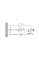
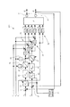
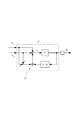
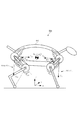
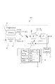
次に、本第1実施形態のロボット装置を図2に示す。図2に示すロボット装置100は、いわゆる1リンクマニピュレータであり、リンク101と、一対のアクチュエータe1,f1からなる駆動部120と、固定部材であるベース部材103及びベース部材103から延びる棒状のアーム部材104とを備えている。
Next, the robot apparatus of the first embodiment is shown in FIG. A
リンク101は、長手部材からなり、その基端101aが固定部材であるアーム部材104の長手方向の先端に揺動可能に支持されている。このリンク101の先端101bには、不図示のエンドエフェクタ(例えばハンド)が設けられている。つまり、リンク101は、関節で揺動可能に支持されている。
The
各アクチュエータe1,f1は、一関節筋アクチュエータであり、一端が固定部材であるベース部材103に接続され、他端がリンク101の基端101aに接続されて、駆動力(収縮力)の差によりリンク101を揺動させるように拮抗配置されている。つまり、アクチュエータe1,f1は、リンク101を挟んでリンク101の両側に対称配置されている。
Each of the actuators e 1 and f 1 is a one-joint muscle actuator, one end of which is connected to the
また、ロボット装置100は、各アクチュエータe1,f1の駆動力を各駆動力指令値により設定して、リンク101の動作を制御する制御装置150を備えている。
The
各アクチュエータe1,f1は、図1に示す空気圧式の人工筋肉アクチュエータである。人工筋肉アクチュエータは収縮方向にのみ力を発生するため、関節を任意の角度に位置決めするために、図2に示すように拮抗して配置されている。つまり、各アクチュエータe1,f1は、人工筋肉からなる一関節筋アクチュエータであるので、収縮することにより駆動力が発生する。したがって、アクチュエータe1,f1の収縮力が駆動力となる。 The actuators e 1 and f 1 are pneumatic artificial muscle actuators shown in FIG. Since the artificial muscle actuator generates force only in the contraction direction, it is arranged in an antagonistic manner as shown in FIG. 2 in order to position the joint at an arbitrary angle. That is, the actuators e 1 and f 1 are one-joint muscle actuators made of artificial muscles, so that a driving force is generated by contraction. Therefore, the contraction force of the actuators e 1 and f 1 becomes the driving force.
拮抗配置されたアクチュエータe1,f1の力発生要素の駆動力(収縮力)をそれぞれue1,uf1、アーム部材104に対するリンク101の揺動角度をθ、リンクの慣性モーメントをIとする。また、モーメントアームの長さ、つまりリンク101の揺動中心点とリンク101におけるアクチュエータe1,f1の接続点との長さをrとする。運動方程式は、以下の式(2)となる。
The driving force (contraction force) of the force generating element of the actuators e 1 and f 1 that are antagonistically arranged is u e1 and u f1 , the swing angle of the
式(2)の右辺第1項における駆動力ue1,uf1の差が関節に回転トルクを与え、右辺第2項、第3項における駆動力ue1,uf1の和が関節におけるリンクの剛性、粘性を変動させることがわかる。 The difference between the driving forces u e1 and u f1 in the first term on the right side of Equation (2) gives rotational torque to the joint, and the sum of the driving forces u e1 and u f1 in the second and third terms on the right side is the link force at the joint. It can be seen that the rigidity and viscosity are changed.
(2)制御系設計
本第1実施形態では、アーム部材104に対するリンク101の揺動角度を目標揺動角度に位置決めし、同時にアーム部材104とリンク101との関節におけるリンク101の剛性を制御することを目的としている。
(2) Control System Design In the first embodiment, the swing angle of the
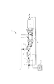
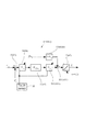
図3に本第1実施形態における制御装置150のブロック線図を示す。制御装置150は、リンク101を第1の揺動方向(図1中、矢印と反対方向)に揺動させる駆動力をアクチュエータe1に発生させる第1の駆動力指令値ue1を生成する。また、制御装置150は、リンク101を第1の揺動方向とは反対の第2の揺動方向(図1中、矢印の方向)に揺動させる駆動力をアクチュエータf1に発生させる第2の駆動力指令値uf1を生成する。そして、制御装置150は、第1の駆動力指令値ue1と第2の駆動力指令値uf1との差に基づき、一対のアクチュエータe1,f1を動作させてリンク101の揺動動作を制御する。これと共に、制御装置150は、第1の駆動力指令値ue1と第2の駆動力指令値uf1との和に基づき一対のアクチュエータe1,f1を動作させてアーム部材104とリンク101との関節の剛性を制御する。
FIG. 3 shows a block diagram of the
ここで、固定部材であるアーム部材104に対するリンク101の目標揺動角度をra、アーム部材104とリンク101との関節におけるリンク101の目標剛性をrsとする。なお、図3中、符号Pで示すブロックは、アクチュエータe1,f1及びリンク101からなるリンク機構を示している。以下、制御装置150の構成について詳細に説明する。
Here, the target swing angle of the
制御装置150は、アーム部材104に対するリンク101の揺動角度θ1を検知する揺動角度検知センサ1と、リンク101に外力が作用したときに外力が作用したことを示す検知信号を出力するタッチセンサ2とを備えている。
The
また、制御装置150は、偏差算出部である減算器3及びゲイン調整器4と、トルク指令生成部であるPID制御器5と、剛性指令値U1にリンク101の揺動中心点を中心とするモーメントアームの長さrを乗算する乗算部としての乗算器6とを備えている。
Further, the
また、制御装置150は、PID制御器5が出力するトルク指令値T1を補正するトルク指令補正部である飽和回路7を備えている。また、制御装置150は、トルク指令値T1及び剛性指令値U1から各アクチュエータe1,f1への駆動力指令値ue1,uf1を演算により求める駆動力指令値演算部8を備えている。
Further, the
以下、各部について詳細に説明する。まず、揺動角度検知センサ1は、ポテンショメータ又はエンコーダ等のセンサであり、図1において、図示は省略しているが、アーム部材104とリンク101との関節に設けられており、アーム部材104の延びる方向を基準とする関節の角度を検知する。
Hereinafter, each part will be described in detail. First, the swing
タッチセンサ2は、不図示のエンドエフェクタ(例えばハンド)又はリンク101に設けられ、エンドエフェクタ又はリンク101に接触物が接触したときに、検知信号を出力する。つまり、リンク101に外力が作用するとは、エンドエフェクタ又はリンク101に接触物が接触することを意味する。
The
減算器3は、揺動角度θ1と目標揺動角度raとの偏差(差分)を示す値(ra−θ1)を算出する。
ゲイン調整器4は、減算器3が出力した偏差を示す値(ra−θ1)に接触ゲインである係数値Gtを乗じて出力する。係数値Gtは、0以上1以下の範囲内の値であり、タッチセンサ2から検知信号がない場合(センサ2からの検知信号の出力が停止されている期間)には、係数値Gt=1として、入力した偏差を示す値(ra−θ1)を出力する。タッチセンサ2から検知信号が出力されている期間は、偏差を示す値(ra−θ1)に0以上1以下の範囲内の値に設定された係数値Gt(本実施形態では、Gt=0)を乗じて、新たな偏差を示す値(つまり、ra−θ1=0)を出力する。
PID制御器5は、偏差を示す値(ra−θ1)に対してPID制御演算を行い、リンク101を揺動させるトルク指令値T1を生成する。即ち、このフィードバック制御系であるPID制御器5は、リンク101の揺動角度θ1と目標揺動角度raとの偏差を補償するための(つまり、揺動角度θ1を目標揺動角度raに近づけるための)トルク指令値T1を出力する。
The
本第1実施形態では、PID制御器5の伝達関数は、
In the first embodiment, the transfer function of the
ここで、式(2)より、 Here, from equation (2),
しかし、以下の式(5)に示す同時に関節におけるリンク101の剛性に関する条件を満たさなければならない。
However, the condition regarding the rigidity of the
ここで、2つの駆動力指令値ue1,uf1の和を示す剛性指令値U1を定義すると、剛性指令値U1は、以下の式(6)となる。 Here, when a stiffness command value U 1 indicating the sum of two driving force command values u e1 and u f1 is defined, the stiffness command value U 1 is expressed by the following equation (6).
従って、剛性指令値U1は、目標剛性rsを用いた以下の式(7)となる。なお、弾性力定数k及びモーメントアームの長さrは定数であるので、目標剛性rsと剛性指令値U1は比例関係にあり同等である。 Therefore, the stiffness command value U 1 can be expressed as the following formula using the target stiffness r s (7). Incidentally, the length r of the elastic force constant k and the moment arm because it is constant, the target stiffness r s and stiffness command value U 1 is equivalent is proportional.
この式(7)を満たすように、駆動力指令値ue1,uf1を決定する必要がある。そこで、トルク指令値T1と剛性指令値U1とを同時に満たすには、式(4)と式(6)をue1,uf1について解き、以下の式(8)とすればよい。 It is necessary to determine the driving force command values u e1 and u f1 so as to satisfy this equation (7). Therefore, in order to satisfy the torque command value T 1 and the stiffness command value U 1 at the same time, the equations (4) and (6) may be solved for u e1 and u f1 to obtain the following equation (8).
しかし、人工筋肉アクチュエータは収縮方向にのみ力を発生する。そのため、以下の式(9)の条件を同時に満たさなければならない。 However, the artificial muscle actuator generates a force only in the contraction direction. Therefore, the condition of the following formula (9) must be satisfied at the same time.
式(8)と式(9)より以下の式(10)の条件が得られる。 From the equations (8) and (9), the condition of the following equation (10) is obtained.
つまりトルク指令値T1は、以下の式(11)の条件となる。 That torque command value T 1 is a condition of the following equation (11).
従って、式(11)の条件を満たしていれば、関節におけるリンク101の剛性が目標剛性rsとなると同時に、トルク指令値T1によりリンク101の揺動角度が目標角度raに位置決めされる。
Therefore, if they meet the condition of formula (11), at the same time the rigidity of the
そこで、本第1実施形態では、乗算器6は、モーメントアームの長さrと剛性指令値U1との乗算値U1×rを算出し、飽和回路7は、式(11)を実現するために、制約関数に従って、トルク指令値T1を、式(12)の値に制約する。
Therefore, in the first embodiment, the
即ち、飽和回路7は、トルク指令値T1の絶対値を、モーメントアームの長さrと剛性指令値U1との乗算値U1×r以下に制約する制約関数に従って、トルク指令値T1を補正する。より具体的には、飽和回路7は、制約関数として飽和関数に従い、PID制御器5で生成したトルク指令値T1の絶対値が乗算値U1×r以下の場合は、PID制御器5で生成したトルク指令値T1をそのまま出力する。また、飽和回路7は、飽和関数に従い、PID制御器5で生成したトルク指令値T1の絶対値が乗算値U1×rを上回った場合は、絶対値が乗算値U1×rに制限された新たなトルク指令値T1を生成して出力する。
That is, the
なお、トルク指令補正部は、上述した飽和回路7である以外に、PID制御器5のゲインを変動させ、式(11)の範囲にトルク指令値T1(制御入力)の大きさを収めるように機能する回路であってもよい。
In addition to the
以下、タッチセンサ2が検知信号を出力していない場合(タッチセンサ2がOFF)について、図3を参照しながら制御装置150の動作を説明する。まず、揺動角度検知センサ1が、リンク101の揺動角度を検知する(揺動角度検知ステップ)。
Hereinafter, the operation of the
そして、減算器3が、リンク101の揺動角度θ1と目標揺動角度raとの偏差を示す値(ra−θ1)を算出する(偏差算出ステップ)。
Then, the
タッチセンサ2がOFFであるので、ゲイン調整器4は、乗算する係数値Gtが1であり、偏差を示す値(ra−θ1)をそのまま出力する。
Since the
PID制御器5は、ゲイン調整器4から取得した偏差を示す値(ra−θ1)に対してPID制御演算を行い、リンク101を揺動させるトルク指令値T1を生成する(トルク指令生成ステップ)。
The
乗算器6は、取得した剛性指令値U1とモーメントアームの長さrとの乗算値U1×rを算出する(乗算ステップ)。モーメントアームの長さrは、予め設定(不図示の記憶装置に記憶)された定数であり、乗算器6が剛性指令値U1を取得したときに、演算により乗算値U1×rを求める。なお、予め乗算値U1×rの計算結果をテーブルデータとして設定(不図示の記憶装置に記憶)しておき、乗算器6が剛性指令値U1を取得したときにテーブルデータを参照して乗算値U1×rを求めてもよい。
The
飽和回路7は、PID制御器5で生成したトルク指令値T1の絶対値が乗算値U1×r以下の場合は、PID制御器5で生成したトルク指令値T1をそのまま出力する。また、飽和回路7は、PID制御器5で生成したトルク指令値T1の絶対値が乗算値U1×rを上回った場合は、絶対値が乗算値U1×r以下に制限された新たなトルク指令値T1を生成して出力する(トルク指令補正ステップ)。
When the absolute value of the torque command value T 1 generated by the
具体的には、飽和回路7は、絶対値が乗算値U1×rとする新たなトルク指令値T1を出力する。例えば、PID制御器5で生成したトルク指令値T1が、U1×rを上回る場合は、新たなトルク指令値T1をU1×rとする。また、PID制御器5で生成したトルク指令値T1が、−U1×rを下回る場合は、新たなトルク指令値T1を−U1×rとする。これにより、トルク指令値T1が式(11)に制限されるので、最終的に求められる各駆動力指令値ue1,uf1が、負の値となることはない。
Specifically, the
そして、駆動力指令値演算部8は、飽和回路7により出力されたトルク指令値T1を用いて、各駆動力指令値ue1,uf1を、(U1+T1/r)/2,(U1−T1/r)/2の演算式に基づいて計算する(駆動力指令値演算ステップ)。なお、剛性指令値U1、トルク指令値T1及びモーメントアームの長さrに対応した(U1+T1/r)/2,(U1−T1/r)/2の計算結果をテーブルデータとして予め設定(不図示の記憶装置に記憶)しておいてもよい。この場合、駆動力指令値演算部8は、剛性指令値U1、トルク指令値T1を取得したときに、(U1+T1/r)/2,(U1−T1/r)/2の演算式に基づいた計算結果を、テーブルデータを参照して求めてもよい。そして、各アクチュエータe1,f1は、各駆動力指令値ue1,uf1に従って空気圧が調整され、各アクチュエータe1,f1の駆動力が各駆動力指令値ue1,uf1に設定される。
Then, the driving force command
以上の動作により、リンク101の揺動角度θ1が目標揺動角度raに調整され、且つ関節におけるリンク101の剛性が目標剛性rs(=U1×k×r2)に調整されように、フィードバック制御により、各駆動力指令値ue1,uf1が設定される。
By the above operation, is adjusted to the swing angle theta 1 is a target swing angle r a link 101, and the rigidity of the
したがって、フィードフォワード制御よりも簡便なフィードバック制御により、リンク101の角度制御と剛性制御の同時制御を実現することができる。これにより、リンク101の目標揺動角度raと目標剛性rs(つまり、剛性指令値U1)が変更されても、フィードフォワード制御のように繰り返し演算を行う必要がないので、迅速にリンク101の揺動角度及び剛性を目標値に調整することができる。
Therefore, simultaneous control of the angle control and the rigidity control of the
ところで、フィードバック制御系のゲインが高い場合には、それによる関節の剛性が支配的になってしまう。つまり、リンク101に外力が作用した場合、リンク101が外力により目標揺動角度raの位置から揺動しようとするので、仮に係数値Gt=1としておくと、揺動角度θ1と目標揺動角度raとの偏差を示す値(ra−θ1)が0ではなくなる。
By the way, when the gain of the feedback control system is high, the resulting joint stiffness becomes dominant. That is, when an external force acts on the
その結果、PID制御器5が出力するトルク指令値T1によりリンク101を目標揺動角度raの定位置に戻すように各アクチュエータe1,f1の駆動力が設定され、リンク101が定位置に位置決めされる。従って、リンク101に外力が作用した時、リンク101が移動しないように各アクチュエータe1,f1の駆動力が設定されるので、リンク101の剛性が目標剛性rsよりも高くなり、リンク101の柔軟性が損なわれてしまうこととなる。
As a result, the driving force of the
そこで、ゲイン調整器4は、タッチセンサ2がリンク101に外力が作用したことを検知して検知信号を出力している期間は、偏差を示す値(ra−θ1)に係数値Gt=0を乗じて、実際に偏差があったとしても偏差なしを示すra−θ1=0を出力する。つまり、ゲイン調整器4は、新たな偏差を示す値(ra−θ1=0)を算出して出力する。
Therefore, the
これにより、PID制御器5は、外力による作用で実際に偏差が生じたとしても、偏差が0であるとして、検知信号を検知する直前の値と同じ値のトルク指令値T1を出力することとなり、リンク101の剛性は、目標剛性rsに維持されることとなる。したがって、リンク101に外力が作用しても、速やかに係数値Gt=0となり、フィードバック制御系が遮断され、リンク101の柔軟性が維持される。
As a result, the
なお、タッチセンサ2がOFFに切り換わったときは、ゲイン調整器4における係数値がGt=1に切り換わり、実際の偏差(ra−θ1)に基づいてフィードバック制御を行うこととなる。
When the
(3)シミュレーション
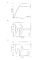
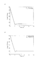
図3の制御装置150を用いてシミュレーションを行った。ここで、リンク101の慣性モーメントをI=8.3×10⁻²[kgm2]、モーメントアームの長さをr=0.1[m]、弾性力定数をk=3、粘性力定数をb=3とする。目標揺動角度raはランプ状とし、初期角度45[deg]から2秒間で目標揺動角度ra=65[deg]に到達する位置決めを行う。
(3) Simulation A simulation was performed using the
このとき、リンク101の関節の目標剛性をrs=U1×k×r2=0.4×k×r2[Nm/rad]と制御する。ここで、弾性力定数k,モーメントアームの長さrは定数であるので、剛性指令値U1をU1=0.4として、実際の関節の剛性が0.4となるように制御すればよい。
At this time, the target stiffness of the joint of the
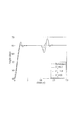
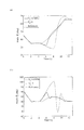
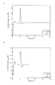
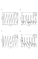
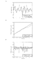
図4(a)にリンク101の揺動角度θ1を実線で示し、目標揺動角度raを破線で示す。また、図4(b)に駆動力指令値ue1,uf1に対する各アクチュエータの実際の駆動力(収縮力、つまり応答)をそれぞれ実線、破線で示す。更に、図4(c)に駆動力指令値ue1,uf1に対するアクチュエータの実際の駆動力の差を実線で、和を破線で、T1/rの応答を一点鎖線で示す。
In FIGS. 4 (a) shows the oscillation angle theta 1 of the
図4(a)より、リンク101の揺動角度θ1は目標揺動角度raに位置決めされていることがわかる。図4(b)より、駆動力指令値ue1,uf1に対する応答はフィードバック制御系のトルク指令値T1を、式(7)と式(10)に示した条件で配分されているが、人工筋肉の駆動力は正の値のみを取るという特性を満たしていることがわかる。図4(c)において、実線で示すuf1−ue1の応答は、一点鎖線で示すT1/rの応答と重なっており、式(3)の条件を満たしている。また、破線で示すuf1+ue1の応答は常に0.4となっており、関節の剛性が目標剛性に制御されていることがわかる。
Fig. 4 (a), the oscillation angle theta 1 of the
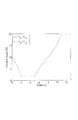
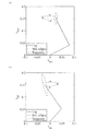
次に、リンク101の先端が外力により押されることを想定するシミュレーションを行う。10秒から11秒にかけて関節角度を正方向に回転させるトルク外乱をリンク101の関節に与えている。タッチセンサ2において接触が発生している間(10秒から11秒)、ゲイン調整器4の係数値Gtを0とする。図5に関節におけるリンク101の目標剛性rsを変化させ、剛性指令値U1を0.3,1.0,10とした場合の応答をそれぞれ実線、破線、点線で示す。
Next, a simulation is performed assuming that the tip of the
実線で示す剛性指令値U1=0.3の応答より、関節の剛性が、剛性指令値U1=1.0,10とした場合の剛性よりも低く制御されているため、外力により大きくリンク101の揺動角度が変位していることがわかる。リンク101への接触物の接触が発生した際に、接触力と同一方向に関節が変位していることから、接触物の接触に対して柔らかい制御が実現していることを示している。そして、目標剛性rs(つまり、剛性指令値U1)を高めるに連れて関節の剛性が高まり、接触に対するリンクの変位量は減少している。
Since the stiffness of the joint is controlled to be lower than the stiffness when the stiffness command value U 1 = 1.0, 10 from the response of the stiffness command value U 1 = 0.3 shown by the solid line, the link is greatly increased by the external force. It can be seen that the swing angle of 101 is displaced. When the contact of the contact object with the
本第1実施形態により、リンク101の目標揺動角度raへの位置決めを実現しながら、自在に関節におけるリンク101の剛性を変化させることが可能であることがわかる。
The present first embodiment, while realizing the positioning of the target oscillating angle r a link 101, freely understood that it is possible to vary the rigidity of the
比較として、式(7)を用いて駆動力指令値ue1,uf1を決定するが、式(10)の条件を考慮せずに制御を行った場合の応答を、図6(a)〜図6(c)に示す。式(10)の条件なしでは、各アクチュエータe1,f1が収縮方向にのみ力を発生する、という制約が考慮されていない。そのため、図6(b)に示すように駆動力指令値は負の値を取ってしまう。各アクチュエータe1,f1は膨張方向には力を発生しないため、負の値の場合は0としてシミュレーションを行った。 For comparison, the driving force command values u e1 and u f1 are determined using the equation (7). The response when the control is performed without considering the condition of the equation (10) is shown in FIGS. As shown in FIG. Without the condition of Equation (10), the constraint that each actuator e 1 , f 1 generates a force only in the contraction direction is not considered. For this reason, the driving force command value takes a negative value as shown in FIG. Since the actuators e 1 and f1 do not generate a force in the expansion direction, the simulation was performed with 0 as a negative value.
その結果、図6(a)に示すように、リンク101は目標揺動角度に制御されているが、図6(c)に示すように、0〜0.3秒と2〜2.3秒では剛性指令値U1に対する応答は目標値の0.4とならず、関節の剛性が目標剛性に制御されていないことがわかる。
As a result, as shown in FIG. 6A, the
[第2実施形態]
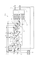
次に、本発明の第2実施形態に係るロボット装置について詳細に説明する。図7は、本発明の第2実施形態に係るロボット装置の概略構成を示す説明図である。本第2実施形態では、人工筋肉アクチュエータを用いた3対6筋を有するリンク機構としての2リンクマニピュレータを備えたロボット装置の手先剛性の制御を例として説明する。
[Second Embodiment]
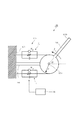
Next, the robot apparatus according to the second embodiment of the present invention will be described in detail. FIG. 7 is an explanatory diagram showing a schematic configuration of the robot apparatus according to the second embodiment of the present invention. In the second embodiment, the control of hand rigidity of a robot apparatus including a two-link manipulator as a link mechanism having three to six muscles using an artificial muscle actuator will be described as an example.
(1)モデリング
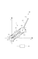
本実施の形態で扱う3対6筋を有するリンク機構としての2リンクマニピュレータを備えたロボット装置を図7に示す。ロボット装置200は、2リンクマニピュレータPを備えている。2リンクマニピュレータPは、第1のリンク201と、第2のリンク202と、固定部材であるプーリ203とを有している。
(1) Modeling FIG. 7 shows a robot apparatus provided with a two-link manipulator as a link mechanism having three-to-six muscles handled in the present embodiment. The
第1のリンク201は、長手部材からなり、その基端201aがプーリ203にx−y直交座標系の平面(以下、「作業平面」という)内で揺動可能に支持されている。第2のリンク202は、長手部材からなり、その基端202aが第1のリンク201の先端201bに作業平面内で揺動可能に支持されている。
The
この第2のリンク202の先端(以下、「リンク先端」という)202bには、不図示のエンドエフェクタ(例えばハンド)が設けられている。つまり、第1のリンク201は、第1の関節と第2の関節との間に配置され、第1の関節で揺動可能に支持されており、第2のリンク202は、第2の関節で揺動可能に支持されている。
An end effector (for example, a hand) (not shown) is provided at the tip (hereinafter referred to as “link tip”) 202 b of the
また、2リンクマニピュレータPは、一対の第1のアクチュエータe1,f1と、一対の第2のアクチュエータe2,f2と、一対の第3のアクチュエータe3,f3と、を備えている。各第1のアクチュエータe1,f1は、一端がプーリ203に接続され、他端が第1のリンク201の長手方向中央部に接続され、駆動力の差により第1のリンク201を揺動させるように拮抗配置されている。
The two-link manipulator P includes a pair of first actuators e 1 and f 1 , a pair of second actuators e 2 and f 2, and a pair of third actuators e 3 and f 3. Yes. Each of the first actuators e 1 and f 1 has one end connected to the
また、各第2のアクチュエータe2,f2は、一端が第1のリンク201の長手方向中央部に接続され、他端が第2のリンク202の基端202aに接続され、駆動力の差により第2のリンク202を揺動させるように拮抗配置されている。また、各第3のアクチュエータe3,f3は、一端がプーリ203に接続され、他端が第2のリンク202の基端202aに接続され、駆動力の差により第1のリンク201及び第2のリンク202を揺動させるように拮抗配置されている。つまり、第1のアクチュエータe1,f1は、第1のリンク201を挟んで第1のリンク201の両側に対称配置されている。また、第2のアクチュエータe2,f2は、第1のリンク201を挟んで第1のリンク201の両側に対称配置されている。また、第3のアクチュエータe3,f3は、第1のリンク201を挟んで第1のリンク201の両側に対称配置されている。
Further, each of the second actuators e 2 and f 2 has one end connected to the longitudinal center of the
また、ロボット装置200は、各アクチュエータe1,f1,e2,f2,e3,f3の駆動力を各駆動力指令値により設定して、リンク201,202の動作を制御する制御装置250を備えている。
Further, the
第1のアクチュエータe1,f1は、第1のリンク201を駆動する第1の一関節駆動アクチュエータである。第2のアクチュエータe2,f2は、第2のリンク202を駆動する第2の一関節駆動アクチュエータである。また、第3のアクチュエータe3,f3は、第1のリンク201と第2のリンク202を同時に駆動する二関節同時駆動アクチュエータである。人の上腕上腕部や下肢大腿部には、二関節筋とよばれる二関節同時駆動アクチュエータが存在することが知られている。人の四肢の筋配列は複雑だが、実効筋概念が導入され、3対6筋を有する2リンクモデルが提示されている。
The first actuators e 1 and f 1 are first joint drive actuators that drive the
各アクチュエータe1,f1,e2,f2,e3,f3は、図1に示す筋の粘弾性特性を有する空気圧式の人工筋肉アクチュエータである。人工筋肉アクチュエータは、筋の粘弾性と呼ばれる特性と類似する特性を有するアクチュエータである。筋は図1に示すように、力発生要素と弾性要素と粘性要素を用いてモデル化される。 The actuators e 1 , f 1 , e 2 , f 2 , e 3 , and f 3 are pneumatic artificial muscle actuators having muscle viscoelastic characteristics shown in FIG. The artificial muscle actuator is an actuator having a characteristic similar to a characteristic called muscle viscoelasticity. As shown in FIG. 1, the muscle is modeled using a force generating element, an elastic element, and a viscous element.
図7のアクチュエータe1,f1,e2,f2,e3,f3について、uen,ufn(n=1,2,3)を力発生要素の駆動力を発生させる駆動力指令値とする。また、ken,kfn,ben,bfn(n=1,2,3)を人工筋肉アクチュエータの弾性力定数、粘性力定数とする。第1,第2のリンク201,202の揺動角度をθ1,θ2、第1,第2のリンク201,202の慣性モーメントをI1,I2、第1,第2のリンク201,202の長さを2×l1,2×l2、第1,第2のリンク201,202の質量をm1,m2とする。
An actuator e 1, f 1, e 2 ,
ここで、第1の揺動角度θ1は、基準軸であるx軸を基準とする第1のリンク201の揺動角度であり、第2の揺動角度θ2は、第1のリンク201の長手方向に延びる軸線を基準とする第2のリンク202の揺動角度である。
Here, the first swing angle θ 1 is the swing angle of the
モーメントアームの長さ、つまり第1のリンク201の揺動中心点とプーリ203におけるアクチュエータe1,f1の接続点との長さ、及び第2のリンク202の揺動中心点と第2のリンク202におけるアクチュエータe2,f2の接続点との長さをrとする。
The length of the moment arm, that is, the length of the swing center point of the
本第2実施形態では、各筋の弾性力定数,粘性力定数をいずれもk,bとすると、2リンクマニピュレータの運動方程式は、以下の式(13)及び式(14)となる。 In the second embodiment, if the elastic force constant and the viscous force constant of each muscle are both k and b, the equations of motion of the two-link manipulator are the following equations (13) and (14).
(2)制御系設計
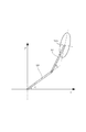
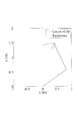
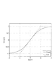
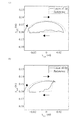
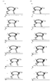
2リンクマニピュレータであるロボット装置200では、手先(ハンド)が外界と直に接触するので、手先剛性、即ちリンク先端202bの剛性を制御することが重要である。手先剛性は、図8に示すような剛性の大きさを示すスティフネス特性を示す楕円(スティフネス楕円)によって表される。
(2) Control system design In the
本第2実施形態では、作業平面内にx−y軸直交座標系を定義し、リンク先端202bにおけるスティフネス特性がx−y軸直交座標系にリンク先端202bを中心とするスティフネス楕円で表される。このスティフネス楕円は、各方向に対する剛性の分布を示し、リンク先端202bとスティフネス楕円の距離が離れるほど剛性が高いことを表している。
In the second embodiment, an xy axis orthogonal coordinate system is defined in the work plane, and the stiffness characteristic at the
図9に本第2実施形態における制御装置250のブロック線図を示す。ここで、固定部材であるプーリ203に対する第1のリンク201の第1の目標揺動角度をra1、第1のリンク201に対する第2のリンク202の第2の目標揺動角度をra2とする。また、プーリ203と第1のリンク201との第1の関節における第1のリンク201の目標剛性をrs1、第1のリンク201と第2のリンク202との第2の関節における第2のリンク202の目標剛性をrs2とする。
FIG. 9 shows a block diagram of the
制御装置250は、プーリ203に対する第1のリンク201の第1の揺動角度θ1を検知する第1の揺動角度検知センサ51と、第1のリンク201に対する第2のリンク202の第2の揺動角度θ2を検知する第2の揺動角度検知センサ61とを備えている。また、制御装置250は、第2のリンク202に外力が作用したときに外力が作用したことを示す検知信号を出力するタッチセンサ52を備えている。
The
また、制御装置250は、第1の偏差算出部である減算器53及びゲイン調整器54と、第1のトルク指令生成部であるPID制御器55と、を備えている。また、制御装置250は、第1の剛性指令値U1に第1のリンク201の揺動中心点を中心とするモーメントアームの長さr1を乗算する第1の乗算部としての乗算器56を備えている。なお、図9では、モーメントアームの長さをr1=rとしている。
The
また、制御装置250は、PID制御器55が出力するトルク指令値T1を補正する第1のトルク指令補正部である飽和回路57を備えている。また、制御装置250は、トルク指令値T1及び剛性指令値U1から各アクチュエータe1,f1への駆動力指令値ue1,uf1を演算により求める第1の駆動力指令値演算部58を備えている。
Further, the
同様に、制御装置250は、第2の偏差算出部である減算器63及びゲイン調整器64と、第2のトルク指令生成部であるPID制御器65と、を備えている。また、制御装置250は、第2の剛性指令値U2に第2のリンク202の揺動中心点を中心とするモーメントアームの長さr2を乗算する第2の乗算部としての乗算器66を備えている。なお、図9では、モーメントアームの長さをr2=rとしている。
Similarly, the
また、制御装置250は、PID制御器65が出力するトルク指令値T2を補正する第2のトルク指令補正部である飽和回路67を備えている。また、制御装置250は、トルク指令値T2及び剛性指令値U2から各アクチュエータe2,f2への駆動力指令値ue2,uf2を演算により求める第2の駆動力指令値演算部68を備えている。
The
以下、各部について詳細に説明する。まず、各揺動角度検知センサ51,61は、ポテンショメータ又はエンコーダ等のセンサであり、図7において、図示は省略しているが、各関節に設けられている。
Hereinafter, each part will be described in detail. First, each swing
タッチセンサ52は、不図示のエンドエフェクタ(例えばハンド)又は第2のリンク202に設けられ、エンドエフェクタ又は第2のリンク202に接触物が接触したときに、検知信号を出力する。つまり、第2のリンク202に外力が作用するとは、エンドエフェクタ又は第2のリンク202に接触物が接触することを意味する。
The
減算器53は、第1の揺動角度θ1と第1の目標揺動角度ra1との第1の偏差(差分)を示す値(ra1−θ1)を算出する。同様に、減算器63は、第2の揺動角度θ2と第2の目標揺動角度ra2との第2の偏差(差分)を示す値(ra2−θ2)を算出する。
The
ゲイン調整器54は、減算器53が出力した第1の偏差を示す値(ra1−θ1)に接触ゲインである第1の係数値Gt1を乗じて出力する。同様に、ゲイン調整器64は、減算器63が出力した第2の偏差を示す値(ra2−θ2)に接触ゲインである第2の係数値Gt2を乗じて出力する。各係数値Gt1,Gt2は、0以上1以下の範囲内の値であり、ゲイン調整器54,64は、タッチセンサ52から検知信号がない場合には、係数値Gt1,Gt2=1として、入力した偏差を示す値(ra1−θ1),(ra2−θ2)を出力する。
The
また、ゲイン調整器54,64は、タッチセンサ52から検知信号が出力されている期間は、偏差を示す値(ra1−θ1),(ra2−θ2)に0以上1以下の範囲内の値の係数値、本実施形態では係数値Gt1,Gt2=0を乗じる。これにより、ゲイン調整器54,64は、新たな偏差を示す値(ra1−θ1=0,ra2−θ2=0)を出力する。
Further, the
PID制御器55は、第1の偏差を示す値(ra1−θ1)に対してPID制御演算を行い、第1のリンク201を揺動させる第1のトルク指令値T1を生成する。即ち、フィードバック制御系であるPID制御器55は、第1のリンク201の第1の揺動角度θ1と第1の目標揺動角度ra1との第1の偏差を補償するための(つまり、揺動角度θ1を目標揺動角度ra1に近づけるための)第1のトルク指令値T1を出力する。
The
同様に、PID制御器65は、第2の偏差を示す値(ra2−θ2)に対してPID制御演算を行い、第2のリンク202を揺動させる第2のトルク指令値T2を生成する。即ち、フィードバック制御系であるPID制御器65は、第2のリンク202の第2の揺動角度θ2と第2の目標揺動角度ra2との第2の偏差を補償するための(つまり、揺動角度θ2を目標揺動角度ra2に近づけるための)第2のトルク指令値T2を出力する。
Similarly, the
第1のアクチュエータe1,f1及び第2のアクチュエータe2,f2の制御方法は、上記第1実施形態と同様である。第nのアクチュエータen,fnに対する駆動力指令値uen,ufn、第nのトルク指令値Tn、第nの剛性指令値Un(ただし、n=1,2)は、以下の式(15)及び式(16)の関係にある。 The control method of the first actuators e 1 and f 1 and the second actuators e 2 and f 2 is the same as that in the first embodiment. Actuator e n of the n, the driving force command value u en for f n, u fn, the torque command value of the n T n, the stiffness command value of the n U n (however, n = 1, 2) are the following It has the relationship of Formula (15) and Formula (16).
そして、トルク指令値T1と剛性指令値U1とを同時に満たすには、駆動力指令値uf1=(U1+T1/r1)/2,駆動力指令値ue1=(U1−T1/r1)/2を満たせばよい。また、トルク指令値T2と剛性指令値U2とを同時に満たすには、駆動力指令値uf2=(U2+T2/r2)/2,駆動力指令値ue2=(U2−T2/r2)/2を満たせばよい。 In order to satisfy the torque command value T 1 and the stiffness command value U 1 simultaneously, the driving force command value u f1 = (U 1 + T 1 / r 1 ) / 2, the driving force command value u e1 = (U 1 − It is sufficient to satisfy T 1 / r 1 ) / 2. Further, in order to satisfy the torque command value T 2 and the stiffness command value U 2 simultaneously, the driving force command value u f2 = (U 2 + T 2 / r 2 ) / 2, the driving force command value u e2 = (U 2 − T 2 / r 2 ) / 2 may be satisfied.
そして、各駆動力指令値は、以下の式(17)の条件を満たす必要がある。 Each driving force command value must satisfy the condition of the following formula (17).
つまりトルク指令値Tnは、以下の式(18)の条件となる。 That is, the torque command value T n is a condition of the following expression (18).
従って、式(18)の条件を満たしていれば、関節におけるリンク201,202の剛性が目標剛性rs1,rs2となると同時に、トルク指令値T1,T2によりリンク201,202の揺動角度が目標角度ra1,ra2に位置決めされる。
Therefore, if the condition of Expression (18) is satisfied, the rigidity of the
本第2実施形態では、乗算器56は、モーメントアームの長さr1と第1の剛性指令値U1との第1の乗算値U1×r1を算出し、飽和回路57は、式(18)を実現するために、トルク指令値T1を、以下の式(19)の値に制約する。同様に、乗算器66は、モーメントアームの長さr2と第2の剛性指令値U2との第2の乗算値U2×r2を算出し、飽和回路67は、式(18)を実現するために、トルク指令値T2を、以下の式(19)の値に制約する。
In the second embodiment, the
即ち、飽和回路57は、第1のトルク指令値T1の絶対値を、モーメントアームの長さr1と第1の剛性指令値U1との第1の乗算値U1×r1以下に制約する第1の制約関数に従って、前記第1のトルク指令値T1を補正する。より具体的には、飽和回路57は、制約関数として飽和関数に従い、PID制御器55で生成した第1のトルク指令値T1の絶対値が第1の乗算値U1×r1以下の場合は、PID制御器55で生成した第1のトルク指令値T1をそのまま出力する。また、飽和回路57は、飽和関数に従い、PID制御器55で生成した第1のトルク指令値T1の絶対値が第1の乗算値U1×r1を上回った場合は、絶対値が第1の乗算値U1×r1以下に制限された新たな第1のトルク指令値T1を生成して出力する。
That is, the
同様に、飽和回路67は、第2のトルク指令値T2の絶対値を、モーメントアームの長さr2と第2の剛性指令値U2との第2の乗算値U2×r2以下に制約する第2の制約関数に従って、前記第2のトルク指令値T2を補正する。より具体的には、飽和回路67は、制約関数として飽和関数に従い、PID制御器65で生成した第2のトルク指令値T2の絶対値が第2の乗算値U2×r2以下の場合は、PID制御器65で生成した第2のトルク指令値T2をそのまま出力する。また、飽和回路67は、飽和関数に従い、PID制御器65で生成した第2のトルク指令値T2の絶対値が第2の乗算値U2×r2を上回った場合は、絶対値が第2の乗算値U2×r2以下に制限された新たな第2のトルク指令値T2を生成して出力する。
Similarly, the
ここで、第3のアクチュエータe3,f3に対する駆動力指令値ue3,uf3に差を与えることによって、第1,第2のアクチュエータと同様に関節にトルクを与えることは可能である。しかし、一つのリンクを複数の位置フィードバック制御系が制御することは冗長であり、フィードバック制御系の設計が複雑になってしまう。 Here, by providing a difference in the third actuator e 3, the driving force command values for f 3 u e3, u f3, first, it is possible to provide a torque in the same manner as in the second actuator joint. However, it is redundant for a plurality of position feedback control systems to control one link, and the design of the feedback control system becomes complicated.
そこで、本第2実施形態では第3のアクチュエータe3,f3は各関節に剛性を与えるために用いる。そこで、駆動力指令値ue3,uf3の差を0、第3の剛性指令値をU3とすると、以下の式(20)の関係となる。 Therefore, in the second embodiment, the third actuators e 3 and f 3 are used to give rigidity to each joint. Therefore, when the difference between the driving force command values u e3 and u f3 is 0 and the third stiffness command value is U 3 , the following equation (20) is established.
これを解くと、駆動力指令値ue3,uf3は、 Solving this, the driving force command values u e3 and u f3 are
そこで、本第2実施形態では、制御装置250は、各第3のアクチュエータe3,f3の駆動力指令値ue3,uf3を、式(21)に示すように、第3の剛性指令値U3の1/2に設定する第3の駆動力指令値演算部78を備えている。
Therefore, in the second embodiment, the
上記第1実施形態の1リンクマニュピレータでは、関節の剛性と手先の剛性は同一であった。本第2実施形態の3対6筋を有する2リンクマニュピレータでは、剛性指令値U1,U2,U3を調整することにより手先の剛性が求まる。 In the one-link manipulator of the first embodiment, the joint rigidity and the hand rigidity are the same. In the two-link manipulator having 3 to 6 lines of the second embodiment, the stiffness of the hand is obtained by adjusting the stiffness command values U 1 , U 2 , U 3 .
例えば、剛性指令値U1,U2,U3を For example, the stiffness command values U 1 , U 2 , U 3 are
以下、スティフネス楕円の長軸及び短軸のうちの一方の軸がx−y軸直交座標系における基準軸であるx軸と平行になる剛性指令値U1,U2,U3を求める。 Hereinafter, stiffness command values U 1 , U 2 , and U 3 are calculated so that one of the long axis and the short axis of the stiffness ellipse is parallel to the x axis that is the reference axis in the xy-axis orthogonal coordinate system.
x−y軸に平行な微小な外力ΔFx,ΔFyによるリンク先端202bの微小な変位をΔxt,Δytとする。また、微小な外力ΔFx,ΔFyによる、各リンク201,202の微小な回転角度をΔθ1,Δθ2とする。微小な回転が起こると、筋の粘弾性を有するアクチュエータは、筋の弾性力によりリンクに微小なトルクΔTp1,ΔTp2を発生させ、以下のような式(23)及び式(24)で表せる。
Let Δx t and Δy t be minute displacements of the
これを行列で表記し、微小な角度とトルクの関係を剛性行列KSで表すと、以下の式(25)となる。 This was expressed in the matrix, to represent the relationship between small angle and torque in the stiffness matrix K S, and becomes the following equation (25).
ここで、ヤコビ行列Jを導入するが、ヤコビ行列Jは、以下の式(26)で表される。 Here, the Jacobian matrix J is introduced. The Jacobian matrix J is expressed by the following equation (26).
これより、微小手先変位と微小外力との関係をコンプライアンス行列JSで表すと、以下の式(27)となる。 Thus, when the relationship between the minute hand displacement and the minute external force is represented by the compliance matrix JS , the following equation (27) is obtained.
コンプライアンス行列の逆行列が剛性を表すので、スティフネス楕円がx−y軸に平行であるという条件は、 Since the inverse matrix of the compliance matrix represents stiffness, the condition that the stiffness ellipse is parallel to the xy axis is
以下、タッチセンサ52が検知信号を出力していない場合(タッチセンサ52がOFF)について、図9を参照しながら制御装置250の動作を説明する。まず、第1の揺動角度検知センサ51が、第1のリンク201の第1の揺動角度θ1を検知する(第1の揺動角度検知ステップ)。同様に、第2の揺動角度検知センサ61が、第2のリンク202の第2の揺動角度θ2を検知する(第2の揺動角度検知ステップ)。
Hereinafter, the operation of the
そして、減算器53が、第1のリンク201の第1の揺動角度θ1と第1の目標揺動角度ra1との第1の偏差を示す値(ra1−θ1)を算出する(第1の偏差算出ステップ)。同様に、減算器63が、第2のリンク202の第2の揺動角度θ2と第2の目標揺動角度ra2との第2の偏差を示す値(ra2−θ2)を算出する(第2の偏差算出ステップ)。
Then, the
タッチセンサ52がOFFであるので、各ゲイン調整器54,64は、乗算する各係数値Gt1,Gt2が1であり、各偏差を示す値(ra1−θ1),(ra2−θ2)をそのまま出力する。
Since the
PID制御器55は、ゲイン調整器54から取得した偏差を示す値(ra1−θ1)に対してPID制御演算を行い、第1のリンク201を揺動させる第1のトルク指令値T1を生成する(第1のトルク指令生成ステップ)。同様に、PID制御器65は、ゲイン調整器64から取得した偏差を示す値(ra2−θ2)に対してPID制御演算を行い、第2のリンク202を揺動させる第2のトルク指令値T2を生成する(第2のトルク指令生成ステップ)。
The
乗算器56は、取得した第1の剛性指令値U1と第1のリンク201のモーメントアームの長さr1との第1の乗算値U1×r1を算出する(第1の乗算ステップ)。同様に、乗算器66は、取得した第2の剛性指令値U2と第2のリンク202のモーメントアームの長さr2との第2の乗算値U2×r2を算出する(第2の乗算ステップ)。
The
ここで、モーメントアームの長さr1,r2は、予め設定(不図示の記憶装置に記憶)された定数である。乗算器56が剛性指令値U1を取得したときに、演算により乗算値U1×r1を求め、乗算器66が剛性指令値U2を取得したときに、演算により乗算値U2×r2を求める。なお、予め乗算値U1×r1の計算結果、乗算値U2×r2の計算結果をテーブルデータとして設定(不図示の記憶装置に記憶)しておいてもよい。そして、乗算器56が剛性指令値U1を取得したときにテーブルデータを参照して乗算値U1×r1を求め、乗算器66が剛性指令値U2を取得したときにテーブルデータを参照して乗算値U2×r2を求めてもよい。
Here, the lengths r 1 and r 2 of the moment arm are constants set in advance (stored in a storage device (not shown)). When the
飽和回路57は、PID制御器55で生成した第1のトルク指令値T1の絶対値が第1の乗算値U1×r1以下の場合は、PID制御器55で生成した第1のトルク指令値T1をそのまま出力する。飽和回路57は、PID制御器55で生成した第1のトルク指令値T1の絶対値が第1の乗算値U1×r1を上回った場合は、絶対値が第1の乗算値U1×r1以下に制限された新たな第1のトルク指令値T1を生成して出力する(第1のトルク指令補正ステップ)。なお、図9では、モーメントアームの長さをr1=rとしている。
When the absolute value of the first torque command value T 1 generated by the
具体的には、飽和回路57は、絶対値が乗算値U1×r1とする新たな第1のトルク指令値T1を出力する。例えば、PID制御器55で生成した第1のトルク指令値T1が、U1×r1を上回る場合は、新たな第1のトルク指令値T1をU1×r1とする。また、PID制御器55で生成した第1のトルク指令値T1が、−U1×r1を下回る場合は、新たなトルク指令値T1を−U1×r1とする。これにより、第1のトルク指令値T1が式(18)に制限されるので、最終的に求められる各駆動力指令値ue1,uf1が、負の値となることはない。
Specifically, the
同様に、飽和回路67は、PID制御器65で生成した第2のトルク指令値T2の絶対値が第2の乗算値U2×r2以下の場合は、PID制御器65で生成した第2のトルク指令値T2をそのまま出力する。飽和回路67は、PID制御器65で生成した第2のトルク指令値T2の絶対値が第2の乗算値U2×r2を上回った場合は、絶対値が第2の乗算値U2×r2以下に制限された新たな第2のトルク指令値T2を生成して出力する(第2のトルク指令補正ステップ)。なお、図9では、モーメントアームの長さをr2=rとしている。
Similarly, when the absolute value of the second torque command value T 2 generated by the
そして第1の駆動力指令値演算部58は、飽和回路57により出力された第1のトルク指令値T1を用いて、各駆動力指令値ue1,uf1を(U1+T1/r1)/2,(U1−T1/r1)/2の演算式に基づいて計算する(第1の駆動力指令値演算ステップ)。同様に、第2の駆動力指令値演算部68は、飽和回路67により出力された第2のトルク指令値T2を用いて、各駆動力指令値ue2,uf2を(U2+T2/r2)/2,(U2−T2/r2)/2の演算式に基づいて計算する(第2の駆動力指令値演算ステップ)。なお、剛性指令値U1、トルク指令値T1及びモーメントアームの長さr1に対応した(U1+T1/r1)/2,(U1−T1/r1)/2の計算結果をテーブルデータとして予め設定(不図示の記憶装置に記憶)しておいてもよい。また、剛性指令値U2、トルク指令値T2及びモーメントアームの長さr2に対応した(U2+T2/r2)/2,(U2−T2/r2)/2の計算結果をテーブルデータとして予め設定(不図示の記憶装置に記憶)しておいてもよい。この場合、駆動力指令値演算部58は、剛性指令値U1、トルク指令値T1を取得したときに、(U1+T1/r1)/2,(U1−T1/r1)/2の演算式に基づいた計算結果を、テーブルデータを参照して求めてもよい。また、駆動力指令値演算部68は、剛性指令値U2、トルク指令値T2を取得したときに、(U2+T2/r2)/2,(U2−T2/r2)/2の演算式に基づいた計算結果を、テーブルデータを参照して求めてもよい。
Then, the first driving force command
以上のフィードバック制御により、各駆動力指令値ue1,uf1が設定されることで、リンク201の揺動角度θ1が目標揺動角度ra1に調整され、且つ第1の関節におけるリンク201の剛性が目標剛性rs1(=U1×k×r1 2)に調整される。同様に、フィードバック制御により、各駆動力指令値ue2,uf2が設定されることで、リンク202の揺動角度θ2が目標揺動角度ra2に調整され、且つ第2の関節におけるリンク202の剛性が目標剛性rs2(=U2×k×r2 2)に調整される。
By setting the driving force command values u e1 and u f1 by the feedback control described above, the swing angle θ 1 of the
したがって、フィードフォワード制御よりも簡便なフィードバック制御により、リンク201,202の角度制御と剛性制御の同時制御を実現することができる。これにより、リンク201,202の目標揺動角度と目標剛性(つまり、剛性指令値U1,U2)が変更されても、フィードフォワード制御のように繰り返し演算を行う必要がないので、迅速にリンクの揺動角度及び関節の剛性を目標値に調整することができる。
Therefore, simultaneous control of the angle control and the rigidity control of the
また、ゲイン調整器54は、タッチセンサ52が第2のリンク202に外力が作用したことを検知して検知信号を出力している期間は、第1の偏差を示す値(ra1−θ1)に第1の係数値Gt1=0を乗じて出力する。つまり、ゲイン調整器54は、実際に偏差があったとしても偏差なしを示す新たな第1の偏差を示す値(ra1−θ1=0)を算出して出力する。
Further, the
同様に、ゲイン調整器64は、タッチセンサ52が第2のリンク202に外力が作用したことを検知して検知信号を出力している期間は、第2の偏差を示す値(ra2−θ2)に第2の係数値Gt2=0を乗じて出力する。つまり、ゲイン調整器64は、実際に偏差があったとしても偏差なしを示す新たな第2の偏差を示す値(ra2−θ2=0)を算出して出力する。
Similarly, the
これにより、各PID制御器55,65は、外力による作用で実際に偏差が生じたとしても、偏差が0であるとして、検知信号を検知する直前の値と同じ値のトルク指令値T1,T2を出力することとなる。したがって、リンク201,202の剛性は、目標剛性に維持され、リンク201,202に外力が作用しても、速やかに係数値Gt1,Gt2=0となり、フィードバック制御系が遮断され、リンク201,202の柔軟性が維持される。
As a result, even if a deviation actually occurs due to the action of an external force, the
なお、タッチセンサ52がOFFに切り換わったときは、各ゲイン調整器54,64における係数値がGt1,Gt2=1に切り換わり、実際の偏差(ra1−θ1),(ra2−θ2)に基づいてフィードバック制御を行うこととなる。
When the
(3)シミュレーション
図9に示した制御装置250を用いてシミュレーションを行った。第1のリンク201と第2のリンク202の物理パラメータは同一とする。リンク201,202の長さを0.5[m]、リンク201,202の慣性モーメントを8.3×10⁻²[kgm2]、モーメントアームの長さr(=r1=r2)を0.1[m]、弾性力定数をk=3、粘性力定数をb=3とする。
(3) Simulation A simulation was performed using the
第1,第2の目標揺動角度はランプ状とし、第1のリンク201は初期角度45[deg]から2秒間で目標揺動角度ra1=35[deg]に到達する位置決めを行う。また、第2のリンク202は初期角度90[deg]から2秒間で目標揺動角度ra2=85[deg]に到達する位置決めを行う。
The first and second target swing angles are ramp-shaped, and the
リンクが位置決めされる目標角度において、リンク先端202bにおけるスティフネス楕円がx−y軸と水平となるように、各アクチュエータの剛性指令値U1,U2,U3を制御する。一関節駆動アクチュエータの剛性指令値U1,U2は任意に設定し、U1=10,U2=5に設定した。このとき、二関節駆動アクチュエータの剛性指令値U3は、式(29)に基づいて、剛性指令値U3=1.907となるように制御すればよい。
The stiffness command values U 1 , U 2 , and U 3 of the actuators are controlled so that the stiffness ellipse at the
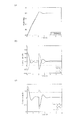
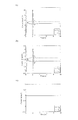
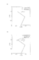
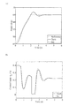
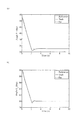
図10(a),図10(b)に、第1,第2のリンク201,202の揺動角度θ1,θ2を実線で、目標揺動角度ra1,ra2を破線で示す。また、図11(a)〜図11(c)に、駆動力指令値uf1,uf2,uf3の応答を実線で、駆動力指令値ue1,ue2,ue3の応答を破線で示す。さらに、図12(a)〜図12(c)に、駆動力指令値uen,ufn(n=1,2,3)の応答の差を実線で、応答の和を破線で、Tn/r(n=1,2)の応答を一点鎖線で示す。
10 (a) and 10 (b), the swing angles θ 1 and θ 2 of the first and
まず、図10(a)及び図10(b)よりリンク201,202は目標揺動角度に位置決めされていることがわかる。次に、図11(a)より、駆動力指令値ue1,uf1は、トルク指令値T1を|T1|≦U1×rに制限した状態で(U1+T1/r)/2,(U1−T1/r)/2の演算式を用いて配分されている。従って、第1のアクチュエータe1,f1の駆動力は正の値を取るという特性を満たしていることがわかる。
First, it can be seen from FIGS. 10A and 10B that the
また、図11(b)より、第2のアクチュエータe2,f2の駆動力も同様に正の値を取っていることがわかる。また、図11(c)より、第3のアクチュエータe3,f3の駆動力は一定値のU3/2である。
Further, from FIG. 11B, it can be seen that the driving force of the second actuators e 2 and f 2 also has a positive value. Further, from FIG. 11 (c), the driving force of the
また、図12(a)において、実線で示すuf1−ue1の応答は、一点鎖線で示すT1/rの応答と重なっており、式(15)の条件を満たしている。また、破線で示すuf1+ue1=U1の応答は常に設定値である10となっている。 In FIG. 12A, the response of u f1 -u e1 indicated by the solid line overlaps with the response of T 1 / r indicated by the alternate long and short dash line, and satisfies the condition of equation (15). Further, the response of u f1 + u e1 = U 1 indicated by a broken line is always 10 which is a set value.
同様に、図12(b)において、実線で示すuf2−ue2の応答は、一点鎖線で示すT2/rの応答と重なっており、式(15)の条件を満たしている。また、破線で示すuf2+ue2=U2の応答は常に設定値である5となっている。 Similarly, in FIG. 12B, the response of u f2 −u e2 indicated by the solid line overlaps with the response of T 2 / r indicated by the alternate long and short dash line, and satisfies the condition of the equation (15). Further, the response of u f2 + u e2 = U 2 indicated by a broken line is always 5 which is a set value.
更に、図12(c)において、実線で示すuf3−ue3の応答は0であり、式(20)の条件を満たしている。また、破線で示すuf3+ue3=U3の応答は常に1.907となっている。各アクチュエータの拮抗対による剛性が目標値に制御されていることから、リンク先端202bのスティフネス楕円は目標角度において、x−y軸と平行になるように制御されていることがわかる。
Further, in FIG. 12C, the response of u f3 -u e3 indicated by a solid line is 0, which satisfies the condition of Expression (20). Moreover, the response of u f3 + u e3 = U 3 indicated by a broken line is always 1.907. Since the rigidity by the antagonistic pair of each actuator is controlled to the target value, it can be seen that the stiffness ellipse of the
次に、リンク先端202bが外力により押されることを想定するシミュレーションを行う。各リンク201,202が目標角度に静定後、リンク先端202bにy軸負方向の外力を与える。接触が発生している間、係数値Gt1,Gt2を0としている。
Next, a simulation is performed assuming that the
図13にリンク先端202bの軌跡を破線で、位置決めの目標軌道を点線で示す。位置決めにおいては、目標軌道に追従している。接触の発生により、係数値Gt1,Gt2を0とすると、マニピュレータは人工筋肉アクチュエータの弾性力によって手先の剛性が制御される。本第2実施形態では、手先剛性はx−y軸方向に平行になるように剛性指令値U1,U2,U3を設定し、設定値を満たすように3対6筋の駆動力を制御している。そのため、y軸負方向の外乱に対して、手先はy軸に平行な方向に柔軟性を発揮していることがわかる。
In FIG. 13, the locus of the
[第3実施形態]
次に、本発明の第3実施形態に係るロボット装置について説明する。図14は、本発明の第3実施形態に係るロボット装置の制御装置を示すブロック線図である。なお、本第3実施形態において、上記第2実施形態と同様の構成については、同一符号を付して説明を省略する。
[Third Embodiment]
Next, a robot apparatus according to a third embodiment of the invention will be described. FIG. 14 is a block diagram showing a control apparatus for a robot apparatus according to the third embodiment of the present invention. Note that, in the third embodiment, the same components as those in the second embodiment are denoted by the same reference numerals, and description thereof is omitted.
上記第2実施形態では、関節が目標角度に到達した後、接触ゲインである係数値Gt1,Gt2を0としてフィードバック制御系を遮断し、筋の弾性による手先剛性の制御を実現した。しかし、目標軌道に追従しながらリンクに柔軟性を持たせるものではない。また、目標角度においてのみスティフネス楕円がx−y軸に平行になる制御を行っていた。 In the second embodiment, after the joint reaches the target angle, the coefficient values G t1 and G t2 that are contact gains are set to 0, the feedback control system is shut off, and the control of the hand stiffness by the elasticity of the muscle is realized. However, the link is not flexible while following the target trajectory. Further, control is performed so that the stiffness ellipse is parallel to the xy axis only at the target angle.
(1)制御系設計
本第3実施形態では、リンク先端202bを目標軌道に追従させながら剛性の制御を同時に行う。また、軌道追従中であっても、スティフネス楕円を常にx−y軸に平行になるように制御する。
(1) Control system design In the third embodiment, rigidity control is performed simultaneously with the
図14に示す制御装置250Aは、演算部70を備えている。演算部70は、第1,第2のリンク201,202に対する目標揺動角度(目標軌道)ra1,ra2に応じて常にスティフネス楕円の軸がx−y軸と平行になるように第3の剛性指令値U3を以下の式(30)に示す演算式により演算する。
A
つまり、演算部70は、図8に示したx−y軸直交座標系で、リンク先端202bにおけるスティフネス楕円の長軸及び短軸のうちの一方の軸が、直交座標系の基準軸(例えばx軸)と平行となるように、剛性指令値U3を演算式により求める。この式(30)に示す演算式は、第1の剛性指令値U1、第2の剛性指令値U2、第1の目標揺動角度ra1、及び第2の目標揺動角度ra2を変数として、第3の剛性指令値U3を求める演算式である。
In other words, the
そして、各パラメータU1,U2,ra1,ra2を入力した演算部70は、式(30)の演算式に基づき、第3の剛性指令値U3を演算により生成する(剛性指令値生成ステップ)。そして、第3の駆動力指令値演算部78は、各駆動力指令値ue3,uf3を、第3の剛性指令値U3に基づいて設定する(第3の駆動力指令値演算ステップ)。本実施形態では、第3の駆動力指令値演算部78は、各駆動力指令値ue3,uf3を、第3の剛性指令値U3に1/2を乗じて得られる値に設定する。これにより、各リンク201,202を各目標揺動角度ra1,ra2に基づいて揺動させるときに、スティフネス楕円の軸がx−y軸に平行となる状態を保つことができる。
Then, the
更に、本第3実施形態ではゲイン調整器54,64の係数値Gt1,Gt2を、タッチセンサ52から検知信号が出力されている期間は、以下の式(31)に示すように、0から1の間で変化させた任意の値とする。
Further, in the third embodiment, the coefficient values G t1 and G t2 of the
係数値Gt1,Gt2に微小な値をとれば、スティフネス楕円の軸は微小にx−y軸から傾くものの、接触物の接触中に各リンク201,202の目標軌道への追従が可能となる。
If the coefficient values G t1 and G t2 are very small, the stiffness ellipse axis slightly tilts from the xy axis, but it is possible to follow the target trajectories of the
特に、第1の係数値Gt1及び第2の係数値Gt2は、タッチセンサ52から検知信号が出力されている期間中、その期間における初期の時点の初期値から時間が経過するに連れて大きくなるように設定されるのがよい。
In particular, the first coefficient value G t1 and the second coefficient value G t2 are displayed as the time elapses from the initial value at the initial point in the period during which the detection signal is output from the
例えば、図15に示すように、タッチセンサ52から検知信号が出力されている期間を時刻4秒から時刻8秒の期間とする。その期間における時刻4秒の時点から時間が経過するに連れて、係数値Gt1,Gt2が大きくなるように設定される。図15に示す例では、各係数値Gt1,Gt2が段階的に大きくなるように設定される。
For example, as shown in FIG. 15, the period during which the detection signal is output from the
本第3実施形態では、係数値Gt1,Gt2は、タッチセンサ52から検知信号が出力されている期間中においても、0とはならないように設定されており、所定の時間が経過したら、1となるように設定される。これにより、接触物が第2のリンク202又はエンドエフェクタに接触した瞬間は、係数値Gt1,Gt2が1よりも低く設定されて、各リンク201,202の柔軟性を保つようにしている。そして、係数値Gt1,Gt2は0ではないので、スティフネス楕円の軸は微小にx−y軸から傾くものの、接触物の接触中に各リンク201,202の目標軌道への追従が可能となる。
In the third embodiment, the coefficient values G t1 and G t2 are set so as not to become 0 even during the period in which the detection signal is output from the
次いで、所定の時間が経過したら、接触中であっても係数値Gt1,Gt2を1とし、各リンク201,202を目標揺動角度及び目標剛性に調整される。従って、各リンク201,202は、接触が生じた瞬間は柔軟性を保ち、その後は迅速に目標の位置に位置決めされるので、制御性が向上する。
Next, when a predetermined time has elapsed, the coefficient values G t1 and G t2 are set to 1 even during contact, and the
(2)シミュレーション
図14に示した制御装置250Aを用いてシミュレーションを行った。リンク201,202の物理パラメータは上記第2実施形態と同様である。目標軌道(目標揺動角度)は、5秒までは上記第2実施形態と同様の軌道である。
(2) Simulation A simulation was performed using the
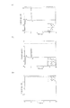
その後11秒までリンク先端202bの軌道がx軸と平行な直線軌道となるように各リンク201,202の目標軌道(目標揺動角度)ra1,ra2を逆運動学により求めている。常にリンク先端202bのスティフネス楕円の軸がx−y軸と水平になるように、各人工筋肉アクチュエータを剛性指令値U1,U2,U3により制御する。一関節駆動アクチュエータの剛性は実施例1と同様に、剛性指令値U1=10,U2=5とし、剛性指令値U3を式(30)より逐次求める。また、接触は4秒から8秒にかけて発生するものとする。そのとき、係数値Gt1,Gt2は、図15に示すように0以外の値を用いる。
図16(a)に第1のリンク201の角度θ1を実線で、目標角度ra1を一点鎖線で示す。また、図16(b)に第2のリンク202の角度θ2を実線で、目標角度ra2を一点鎖線で示す。また、比較として、第2実施形態で示した、接触中は常に係数値Gt1,Gt2を0とする制御(「接触ゲイン0制御」と称す)の応答を破線で示す。さらに、図17に駆動力ue3,uf3の差を実線で、和を破線で示す。
FIG. 16A shows the angle θ 1 of the
図16(a)及び図16(b)より、本第3実施形態の制御装置250Aは、4秒で接触が発生するとフィードバック制御系が遮断されてリンク先端202bの柔らかさを発揮する。そして、第1のリンク201は6秒で、第2のリンク202は7秒で係数値を1としてフードバック制御系の遮断を解除しているため、8秒以降は目標軌道へと収束している。
16A and 16B, in the
一方、破線で示す接触ゲイン0制御では、接触が発生している8秒までフィードバック制御が遮断されている。そのため、8秒以降に大きくなった角度偏差に対して急激に目標軌道への復帰動作が発生し、大きなオーバシュートを発生している。
On the other hand, in the
図17において、破線で示すuf3+ue3=U3は式(30)に示したように目標角度ra1,ra2に応じて逐次演算されている。これにより、スティフネス楕円は軌道追従中において、x−y軸と平行になるように制御されている。 In FIG. 17, u f3 + u e3 = U 3 indicated by a broken line is sequentially calculated according to the target angles r a1 and r a2 as shown in the equation (30). Thus, the stiffness ellipse is controlled to be parallel to the xy axis during the trajectory tracking.
図18(a)にリンク先端202bの軌跡を破線で、位置決めの目標軌道を点線で示す。比較として、図18(b)に接触ゲイン0制御のリンク先端202bの軌跡を破線で、位置決めの目標軌道を点線で示す。
In FIG. 18A, the locus of the
本第3実施形態の制御装置250Aでは、接触が発生した後にリンク先端202bが柔軟性を持つが、同時に軌道追従を行い、リンク先端202bをx軸に水平な方向の軌道に追従させていることがわかる。接触ゲイン0制御では、接触中は軌道制御を行わないため、リンク先端202bの柔軟性は大きいが、目標軌道から大きく外れてしまうことがわかる。
In the
[第4実施形態]
次に、本発明の第4実施形態に係るロボット装置について説明する。図19は、本発明の第4実施形態に係るロボット装置の制御装置における要部を示すブロック線図である。なお、本第4実施形態において、上記第2,第3実施形態と同様の構成については、同一符号を付して説明を省略する。
[Fourth Embodiment]
Next, a robot apparatus according to a fourth embodiment of the present invention will be described. FIG. 19 is a block diagram showing the main part of the control apparatus of the robot apparatus according to the fourth embodiment of the present invention. Note that in the fourth embodiment, identical symbols are assigned to configurations similar to those in the second and third embodiments and descriptions thereof are omitted.
上記第2実施形態ではフィードバック制御系の入力部を遮断したが、十分に関節が静定していない状態では、遮断時にスパイク状のトルク指令値を発生する可能性がある。上記第2,第3実施形態では、第1のトルク指令生成部がPID制御器55であり、第2のトルク指令生成部がPID制御器65である場合について説明したが、本第4実施形態では、第1,第2のトルク指令生成部の構成が異なるものである。
In the second embodiment, the input unit of the feedback control system is shut off. However, when the joint is not sufficiently settled, a spike-like torque command value may be generated when the joint is shut off. In the second and third embodiments, the case where the first torque command generation unit is the
具体的に説明すると、第1のトルク指令生成部455は、PID制御器55と、PID制御器55の出力側に設けられ、PID制御器55が出力した演算結果に第1の係数値Gt1を乗じるゲイン調整器55Aとを有している。
More specifically, the first
また、第1のトルク指令生成部455は、PID制御器55の制御入力をフィードフォワード入力ffw1として入力し、その入力ffw1に(1−Gt1)の値を乗じるゲイン調整器55Bを有している。また、第1のトルク指令生成部455は、ゲイン調整器55Aの出力値とゲイン調整器55Bの出力値とを加算処理し、加算結果を第1のトルク指令値T1として出力する加算器55Cを有している。
The first
第2のトルク指令生成部465は、第1のトルク指令生成部455と構成が同一であり、図19を参照して説明する。第2のトルク指令生成部465は、PID制御器65と、PID制御器65の出力側に設けられ、PID制御器65が出力した演算結果に第2の係数値Gt2を乗じるゲイン調整器65Aとを有している。
The second torque
また、第2のトルク指令生成部465は、PID制御器65の制御入力をフィードフォワード入力ffw2として入力し、その入力ffw2に(1−Gt2)の値を乗じるゲイン調整器65Bを有している。また、第2のトルク指令生成部465は、ゲイン調整器65Aの出力値とゲイン調整器65Bの出力値とを加算処理し、加算結果を第2のトルク指令値T2として出力する加算器65Cを有している。
The second
ここで、フィードフォワード入力ffwn(n=1,2)は、タッチセンサ52が検知信号を出力する直前にPID制御器55,65が出力したPID制御演算による演算結果である。
Here, the feedforward input ffw n (n = 1, 2) is a calculation result by the PID control calculation output by the
これにより、タッチセンサ52から検知信号が出力されている期間は、PID制御器55は、第1の偏差を示す値(ra1−θ1)に対してPID制御演算を行うが、ゲイン調整器55Aは、その演算結果に対して第1の係数値Gt1を乗じる。ゲイン調整器55Bは、フィードフォワード入力ffw1を入力し、その入力ffw1に(1−Gt1)の値を乗じる。加算器55Cは、ゲイン調整器55Aの出力値とゲイン調整器55Bの出力値との加算結果を第1のトルク指令値T1として出力する。
Thereby, during the period when the detection signal is output from the
同様に、タッチセンサ52から検知信号が出力されている期間は、PID制御器65は、第2の偏差を示す値(ra2−θ2)に対してPID制御演算を行うが、ゲイン調整器65Aは、その演算結果に対して第2の係数値Gt2を乗じる。ゲイン調整器65Bは、フィードフォワード入力ffw2を入力し、その入力ffw2に(1−Gt2)の値を乗じる。加算器65Cは、ゲイン調整器65Aの出力値とゲイン調整器65Bの出力値との加算結果を第2のトルク指令値T2として出力する。
Similarly, during the period when the detection signal is output from the
具体例を挙げて説明すると、タッチセンサ52が接触を検知して係数値Gtn=0となった場合は、(1−Gtn)=1となり、トルク指令生成部455,465が出力するトルク指令値Tnは、タッチセンサ52が接触を検知する直前の値となる。
Explaining with a specific example, when the
従って、各リンク201,202の動作中にタッチセンサ52により接触が検知された場合には、偏差が0となる場合のトルク指令値で制御するフィードバック制御に移行するのではなく、接触が生じる直前の偏差に基づくトルク指令値でフィードバック制御する。なお、上記第3実施形態と同様に、検知信号を検知してから時間が経過するに連れて、係数値Gt1,Gt2を大きくしていってもよい。そして、接触が生じた瞬間に係数値Gt1,Gt2=0とならない、1よりも小さな値に係数値Gt1,Gt2を設定してもよい。
Therefore, when contact is detected by the
以上、本第4実施形態によれば、各リンク201,202の動作中に、各リンク201,202の柔軟性を損なうことなく、トルク指令値T1,T2のスパイクを防止することができ、制御性が更に向上する。
As described above, according to the fourth embodiment, spikes of the torque command values T 1 and T 2 can be prevented during the operation of the
[第5実施形態]
次に、本発明の第5実施形態に係るロボット装置について説明する。上記第1〜4実施形態では、ロボット装置が作業ロボットとしてのマニピュレータである場合について説明したが、上記第1〜第4実施形態に示した制御装置を、歩行ロボットの脚制御に用いることが可能である。
[Fifth Embodiment]
Next, a robot apparatus according to a fifth embodiment of the invention will be described. In the first to fourth embodiments, the case where the robot apparatus is a manipulator as a work robot has been described. However, the control apparatus shown in the first to fourth embodiments can be used for leg control of a walking robot. It is.
歩行ロボットでは地面との接地時に脚の剛性を低くすることで、不整地に対する歩行の安定性が高まる。また、接地時にスティフネス楕円を地面と平行にすることにより、地面に対する滑りを抑制することが可能である。しかし、支持脚相では脚の剛性を高くして、体を支持する必要がある。 In walking robots, the stability of walking with respect to rough terrain is increased by reducing the rigidity of the legs when touching the ground. In addition, slipping with respect to the ground can be suppressed by making the stiffness ellipse parallel to the ground at the time of grounding. However, in the supporting leg phase, it is necessary to increase the rigidity of the legs to support the body.
これに対して、図20に、上記第3実施形態で示した剛性と追従の同時制御を適用した場合のシミュレーションによるスティック線図を示す。破線で脚先の軌道を、点線で目標軌道を示している。これより、接地時は脚の剛性は低いため柔らかく地面に接地し、支持脚相が進むにつれて脚の剛性が高まり、目標軌道に追従していることがわかる。 On the other hand, FIG. 20 shows a stick diagram by simulation in the case where the simultaneous control of rigidity and follow-up shown in the third embodiment is applied. The broken line indicates the trajectory of the leg tip, and the dotted line indicates the target trajectory. From this, it can be seen that when the ground is touched, the leg stiffness is low, so that the leg is softly touched to the ground, and the leg stiffness increases as the supporting leg phase advances, following the target trajectory.
[第6実施形態]
次に、本発明の第6実施形態に係るロボット装置について説明する。上記第1〜第5実施形態では、拮抗配置された人工筋肉アクチュエータを用いて位置決めと剛性の同時制御を行った。本第6実施形態では、関節に回転モータを用いる1リンクアームに対して、本発明の制御系を適用する。
[Sixth Embodiment]
Next, a robot apparatus according to a sixth embodiment of the present invention will be described. In the said 1st-5th embodiment, positioning and rigidity simultaneous control were performed using the artificial muscle actuator arranged antagonistically. In the sixth embodiment, the control system of the present invention is applied to one link arm that uses a rotary motor for the joint.
ロボット装置の構成は、駆動部として、図2に示すアクチュエータe1,f1の代わりに、図21のブロック線図に示す回転モータP0に置き換えたものである。なお、ロボット装置の制御装置は、回転モータP0を駆動するモータ回路P1を有している。回転モータP0は、図2を参照し、固定部材であるアーム部材104とリンク101との関節に配置され、リンク101を揺動させる駆動部である。1リンクアームの運動方程式を以下の式(32)のように定義する。
The configuration of the robot apparatus is such that the drive unit is replaced with a rotary motor P 0 shown in the block diagram of FIG. 21 instead of the actuators e 1 and f 1 shown in FIG. The control apparatus for a robot apparatus, and a motor circuit P 1 for driving the rotation motor P 0. Referring to FIG. 2, the rotary motor P 0 is a drive unit that is disposed at a joint between the
ここで、umは回転モータが発生する制御トルクである。つぎに、比例ゲインをk、微分ゲインをb、仮想的なモーメントアームの長さをr、仮想的な筋の駆動力を発生させる駆動力指令値をue1,uf1として、1リンクアームに対して以下の式(33)のような比例−微分フィードバック制御系を構成する。 Here, u m is a control torque generated by the rotary motor. Next, the proportional gain is k, the differential gain is b, the virtual moment arm length is r, and the driving force command values for generating the virtual muscle driving force are u e1 and u f1. On the other hand, a proportional-derivative feedback control system such as the following equation (33) is configured.
ここで、第1項はトルク指令値、第2項、第3項は仮想的な筋の駆動力指令値ue1,uf1によりゲインが変動する比例−微分フィードバック制御系となっている。 Here, the first term is a torque command value, and the second and third terms are a proportional-differential feedback control system in which the gain varies depending on virtual muscle driving force command values u e1 and u f1 .
図21に示すモータ回路P1は、式(32)と式(33)で構成されるフィードバック制御系である。モータ回路P1は、駆動力指令値ue1,uf1を入力として、回転モータP0を動作させ、回転モータP0にリンク101を駆動させて揺動角度θ1を出力とするシステムであることがわかる。式(32)及び式(33)は、第1実施形態の式(2)で示した人工筋肉アクチュエータを用いた1リンクアームの運動方程式と同一である。これより、回転モータを用いた1リンクアームに対して、式(33)のように比例−微分フィードバックを施すことで、第1実施形態に示した位置と剛性の同時制御方法をそのまま適用することができることがわかる。
Motor circuits P 1 shown in FIG. 21 is a feedback control system comprised of the formula (32) and equation (33). Motor circuits P 1 is input with a driving force command value u e1, u f1, to operate the rotation motor P 0, the rotation motor P 0 drives the
具体的に説明すると、図21に示すモータ回路P1は、回転モータP0を、駆動力の差によりリンク101を揺動させる一対の仮想アクチュエータと見做せるように構成されている。そして、図3に示す制御装置150と同一構成の制御装置によって、各仮想アクチュエータの駆動力を、各駆動力指令値ue1,uf1により調整して、リンク101の動作を制御する。
Specifically, the motor circuit P 1 shown in FIG. 21, the rotation motor P 0, is configured to a pair of virtual actuator regarded for swinging the
図3を参照して、制御装置の各部の動作について説明すると、まず、揺動角度検知センサ1は、揺動角度(関節の角度)θ1を検知する。偏差算出部としての減算器3は、アーム部材104に対するリンク101の揺動角度θ1と目標揺動角度raとの偏差(差分)を示す値を算出する(偏差算出ステップ)。
Referring to FIG. 3, to describe the operation of each unit of the control device, first, the swing
トルク指令生成部としてのPID制御器5は、偏差を示す値に対してPID制御演算を行い、リンク101を揺動させるトルク指令値T1を生成する(トルク指令生成ステップ)。
The
乗算部としての乗算器6は、リンク101の揺動中心点を中心とする仮想のモーメントアームの長さrと、各駆動力指令値ue1,uf1の和を示す剛性指令値U1との乗算値U1×rを算出する(乗算ステップ)。仮想のモーメントアームの長さrは、予め設定(不図示の記憶装置に記憶)された定数であり、乗算器6が剛性指令値U1を取得したときに、演算により乗算値U1×rを求める。なお、予め乗算値U1×rの計算結果をテーブルデータとして設定(不図示の記憶装置に記憶)しておき、乗算器6が剛性指令値U1を取得したときにテーブルデータを参照して乗算値U1×rを求めてもよい。
The
トルク指令補正部としての飽和回路7は、PID制御器5で生成したトルク指令値T1の絶対値が乗算値U1×r以下の場合は、PID制御器5で生成したトルク指令値T1をそのまま出力する。また、飽和回路7は、PID制御器5で生成したトルク指令値T1の絶対値が乗算値U1×rを上回った場合は、絶対値が乗算値U1×r以下に制限された新たなトルク指令値T1を出力する(トルク指令補正ステップ)。
When the absolute value of the torque command value T 1 generated by the
駆動力指令値演算部8は、飽和回路7により出力されたトルク指令値T1を用いて、各駆動力指令値ue1,uf1を、(U1+T1/r)/2,(U1−T1/r)/2の演算式に基づいて計算する(駆動力指令値演算ステップ)。なお、剛性指令値U1、トルク指令値T1及び仮想モーメントアームの長さrに対応した(U1+T1/r)/2,(U1−T1/r)/2の計算結果をテーブルデータとして予め設定(不図示の記憶装置に記憶)しておいてもよい。この場合、駆動力指令値演算部8は、剛性指令値U1、トルク指令値T1を取得したときに、(U1+T1/r)/2,(U1−T1/r)/2の演算式に基づいた計算結果を、テーブルデータを参照して求めてもよい。
The driving force command
これにより、フィードフォワード制御よりも簡便なフィードバック制御により、リンク101の角度制御と関節におけるリンク101の剛性制御の同時制御を実現することができる。これにより、リンク101の揺動角度と剛性の目標値が変更されても、繰り返し演算を行う必要がないので、迅速にリンク101の揺動角度及び剛性を目標値に調整することができる。
Thereby, simultaneous control of the angle control of the
また、本第6実施形態では、制御装置は、ゲイン調整器4を有し、タッチセンサ2から検知信号が出力されている期間は、偏差を示す値に0を乗じて新たな偏差(ra−θ1=0)を示す値を算出する。これにより、PID制御器5は、外力による作用で実際に偏差が生じたとしても、偏差が0であるとして、検知信号を検知する直前の値と同じ値のトルク指令値T1を出力することとなり、リンク101の剛性は、目標剛性rsに維持されることとなる。したがって、リンク101に外力が作用しても、速やかに係数値Gt=0となり、フィードバック制御系が遮断され、リンク101の柔軟性が維持される。
In the sixth embodiment, the control device includes the
[第7実施形態]
上記第1〜第6実施形態では、式(11)および式(18)に示した制御入力の制約を行うために、図22の破線で示す飽和関数を用いてきた。しかし、図22の破線で示す飽和関数のように微分不可能な関数を用いて制御入力の制約を行うと、制約時に制御入力が急峻に変動してしまうことがある。このような制御入力は、制御対象の機械系高次振動を励起し、制御系が不安定となることがある。
[Seventh Embodiment]
In the first to sixth embodiments, the saturation function indicated by the broken line in FIG. 22 has been used in order to restrict the control input shown in Expression (11) and Expression (18). However, if the control input is restricted using a non-differentiable function such as the saturation function shown by the broken line in FIG. 22, the control input may fluctuate sharply at the time of restriction. Such a control input excites mechanical high-order vibrations to be controlled, and the control system may become unstable.
そこで、本第7実施形態では、制約関数として、制御入力の制約に微分可能な関数である双曲線正接関数を用いる。双曲線正接関数を図22の実線で示す。この双曲線正接関数は、漸近線が乗算値±Un×rn(n=1,2)である。双曲線正接関数で制約されるトルク指令値(フィードバック制御トルク)Ttn(n=1,2)は、制約される前のトルク指令値Tn、制御入力の和Unおよびプーリ径rを用いて以下のように表すことができる。 Therefore, in the seventh embodiment, a hyperbolic tangent function that is a differentiable function for the control input constraint is used as the constraint function. The hyperbolic tangent function is shown by the solid line in FIG. In this hyperbolic tangent function, the asymptote is a multiplication value ± U n × r n (n = 1, 2). The torque command value (feedback control torque) T tn (n = 1, 2) restricted by the hyperbolic tangent function is obtained by using the torque command value T n before the restriction, the sum U n of the control inputs, and the pulley diameter r. It can be expressed as follows:
上記第1実施形態では1リンクアームの制御を行った。本第7実施形態では、第1実施形態で用いた図3のブロック線図中の飽和関数を、±U1×rを漸近線とする双曲線正接関数に置き換えシミュレーションを行う。図23(a)に関節の角度θ1と目標角度raを示し、実線で双曲線正接関数を用いる関節角度の応答を、破線で飽和関数を用いた関節角度の応答を、点線で目標角度を示す。また、図23(b)に駆動力uf1の、制約に双曲線正接関数と飽和関数を用いた応答をそれぞれ実線、破線で示す。駆動力uf1は、トルク指令値T1により式(8)を用いて決定される。そのため、実線で示す制約に双曲線正接関数を用いる応答では、トルクT1が制約される約0.7sと約2.5sにおいて、駆動力uf1の応答に急峻な変動が現れなくなっていることがわかる。また、図23(a)より、制御入力の飽和に双曲線正接関数を用いても、位置決め性能に劣化はないことがわかる。 In the first embodiment, one link arm is controlled. In the seventh embodiment, a simulation is performed by replacing the saturation function in the block diagram of FIG. 3 used in the first embodiment with a hyperbolic tangent function having ± U 1 × r as an asymptotic line. Figure 23 (a) to indicate the angle theta 1 and the target angle r a of the joint, the response of the joint angle using the hyperbolic tangent function with a solid line, the response of the joint angle using saturation function by a broken line, the target angle by the dotted line Show. FIG. 23 (b) shows the response of the driving force u f1 using a hyperbolic tangent function and a saturation function as constraints, respectively, as a solid line and a broken line. Driving force u f1 is the torque command value T 1 is determined using equation (8). Therefore, in the response using the hyperbolic tangent function for the constraint indicated by the solid line, the steep fluctuation does not appear in the response of the driving force u f1 at about 0.7 s and about 2.5 s where the torque T 1 is restricted. Recognize. Further, FIG. 23A shows that the positioning performance is not deteriorated even if a hyperbolic tangent function is used for saturation of the control input.
上記第2実施形態では2リンクアームの制御を行った。1リンクアームの制御と同様に、本第7実施形態では、上記第2実施形態で用いた図9のブロック線図中の飽和関数を、双曲線正接関数に置き換えシミュレーションを行う。具体的には、第1の制約関数が、±U1×r1を漸近線とする双曲線正接関数であり、第2の制約関数が、±U2×r2を漸近線とする双曲線正接関数である。 In the second embodiment, the two link arms are controlled. Similar to the control of one link arm, in the seventh embodiment, a simulation is performed by replacing the saturation function in the block diagram of FIG. 9 used in the second embodiment with a hyperbolic tangent function. Specifically, the first constraint function is a hyperbolic tangent function having ± U 1 × r 1 as an asymptote, and the second constraint function is a hyperbolic tangent function having ± U 2 × r 2 as an asymptote. It is.
図24(a),(b)に、第1及び第2のリンク201,202の関節角度θ1,θ2と目標角度ra1,ra2を示し、実線で双曲線正接関数を用いる応答を、破線で飽和関数を用いた応答を、点線で目標角度を示す。また、図25(a)及び図25(b)に駆動力uf1,uf2の、双曲線正接関数と飽和関数を用いた応答をそれぞれ実線、破線で示す。図25(a)より、第1のリンク201に対するトルクT1が制約される約0.2sと約2.2sにおいて、双曲線正接関数により駆動力uf1の応答に急峻な変動が現れなくなっていることがわかる。上記第2実施形態では、第2のリンク202に対するトルクT2が制約の範囲内であるため、駆動力uf2は制約される必要がない。しかし、図22より双曲線正接関数は制約の範囲内であっても信号を低減する効果がある。そのため、図25(b)に示す本第7実施形態の双曲線正接関数による駆動力uf2は飽和関数による駆動力と若干の差異が生じているが、図24(a),(b)から双曲線正接関数を用いても位置決め性能に変化はないことがわかる。
FIG. 24 (a), the (b), the joint angle theta 1 of the first and
[第8実施形態]
本第8実施形態では、接触ゲインの調整が不要で、また、大きな障害物への着地であっても緩やかな脚制御を可能とする歩行制御系を設計する。さらに、4足歩行ロボットのモデルを用いてシミュレーションを行い、本第8実施形態で提案している制御系により不整地歩行が可能であることを示す。
[Eighth Embodiment]
In the eighth embodiment, a gait control system is designed that does not require contact gain adjustment and that allows gentle leg control even when landing on a large obstacle. Furthermore, a simulation is performed using a model of a quadruped walking robot, and it is shown that rough terrain walking is possible by the control system proposed in the eighth embodiment.
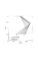
(1)モデリング
図26は、本発明の第8実施形態に係るロボット装置としての4足歩行ロボットのリンク配置と筋配置および座標系を示す側面図である。ロボット装置としての4足歩行ロボット800は、固定部材としての胴体803と、4つの支持脚となる4つのリンク機構RF,LF,RH,LHとを備えている。これら4つのリンク機構RF,LF,RH,LHが胴体803に接続されている。
(1) Modeling FIG. 26 is a side view showing a link arrangement, a muscle arrangement, and a coordinate system of a quadruped walking robot as a robot apparatus according to the eighth embodiment of the present invention. A
ここで、絶対座標系は、x−y平面については紙面内に取り、z座標は紙面に垂直で紙面の裏から表の向きに取る。座標(xG,yG,zG)は胴体803の重心の位置を表し、本第8実施形態では胴体803の重心を中心としてx軸まわり右ねじ方向の傾きをロール、z軸まわり右ねじ方向の傾きをピッチ、y軸まわり右ねじ方向の傾きをヨーと記す。
Here, the absolute coordinate system is taken in the drawing with respect to the xy plane, and the z coordinate is taken from the back of the drawing to the front direction from the back of the drawing. The coordinates (x G , y G , z G ) represent the position of the center of gravity of the
本第8実施形態では、右後脚がリンク機構RH、右前脚がリンク機構RF、左後脚がリンク機構LH、左前脚がリンク機構LFである。これら右後脚、右前脚、左後脚及び左前脚に対して、それぞれ支持脚にローカルなxRH−yRH、xRF−yRF、xLH−yLHおよびxLF−yLF座標系を設定する。図26にはxRH−yRH座標系およびxRF−yRF座標系のみ図示している。ここで支持脚に対する座標系は、x−y座標の軸がロボット装置の胴体803の底面部分と水平になるように設定する。
In the eighth embodiment, the right rear leg is the link mechanism RH, the right front leg is the link mechanism RF, the left rear leg is the link mechanism LH, and the left front leg is the link mechanism LF. For these right hind leg, right front leg, left hind leg and left front leg, local x RH -y RH , x RF -y RF , x LH -y LH and x LF -y LF coordinate systems are respectively provided on the support legs. Set. FIG. 26 shows only the x RH -y RH coordinate system and the x RF -y RF coordinate system. Here, the coordinate system for the support leg is set so that the axis of the xy coordinate is horizontal with the bottom surface portion of the
本第8実施形態で制御対象とする4足歩行ロボット800は、前脚RF,LFは2リンクマニピュレータ、後脚RH,LHは3リンクマニピュレータとするが、後脚は第3リンクの角度が90degに固定された等価的な2リンクマニピュレータとして用いる。そのため、前脚と後脚の双方について、上記第2実施形態に示した3対6筋を有する2リンクマニピュレータに対する制御手法を適用することが可能である。
The
また、脚先端部には球状の足を設定する。尾と首には質量を設定しているが、頭部には質量を設定していない。この4足歩行ロボットは機構解析ソフトウェアRecurdynを用いてモデル化され、本第8実施形態において不整地歩行シミュレーションに用いる。 A spherical foot is set at the leg tip. Mass is set for the tail and neck, but no mass is set for the head. This quadruped walking robot is modeled by using mechanism analysis software Recurdyn, and is used for rough terrain walking simulation in the eighth embodiment.
前脚RF,LFおよび後脚RH,LHの第n(n=1,2)のリンクのパラメータは、以下のとおりである。具体的には、リンク長lFn,lHnは、lF1=0.070m,lF2=0.12m,lH1=0.090m,lH2=0.1235mである。また、慣性モーメントIFn,IHnは、IF1=11.74×10⁻⁶kg・m2,IF2=52.959×10⁻⁶kg・m2,IH1=22.81×10⁻⁶kg・m2,IH2=94.35×10⁻⁶kg・m2である。また、質量MFn,MHnは、MF1=2.16×10⁻²kg,MF2=3.6298×10⁻²kg,MH1=2.71×10⁻²kg,MH2=5.2558×10⁻²kgである。また、胴体803のx,z方向の長さは、lbx=0.28m,lbz=0.05m、z方向の脚の付け根の間隔は、lbl=0.15m、質量MbはMb=0.7309kg、プーリ径、足球半径は、r=0.02m,rf=0.008mである。人工筋肉アクチュエータの弾性力定数、粘性力定数は、k=150.5N/m,b=0.01N・s/mである。なお、人工筋肉アクチュエータの弾性力定数は、神田通信工業製マッキベン型アクチュエータ0.25インチタイプを測定して求めている。
The parameters of the n-th (n = 1, 2) links of the front legs RF and LF and the rear legs RH and LH are as follows. Specifically, the link lengths l Fn and l Hn are l F1 = 0.070 m, l F2 = 0.12 m, l H1 = 0.090 m, and l H2 = 0.1235 m. The moments of inertia I Fn and I Hn are I F1 = 11.74 × 10 −6 kg · m 2 , I F2 = 52.959 × 10 −6 kg · m 2 , I H1 = 22.81 × 10 − 6 kg · m 2 , I H2 = 94.35 × 10 −6 kg · m 2 . The mass M Fn, M Hn is, M F1 = 2.16 × 10 -2 kg, M F2 = 3.6298 × 10 -2 kg, M H1 = 2.71 × 10 -2 kg, M H2 = 5 2558 × 10 −2 kg. The length of the
(2)制御系設計
まず、各支持脚RF〜LHに対して、足先の軌道とスティフネス楕円を設定する。軌道は、遊脚相では足先が楕円の上半分を描く軌道とし、支持脚相では直線軌道とする。また、歩幅は0.06mと設定する。本第8実施形態では、不整地において、支持脚に予期しない着地が生じた際に胴体803と垂直な方向に剛性を発揮させることで安定的な歩行を行う。そのため、スティフネス楕円は、上記第2実施形態で示した方法を用いて、各支持脚のローカルな座標系に垂直になるように設定する。
(2) Control system design First, for each of the support legs RF to LH, the foot trajectory and the stiffness ellipse are set. The trajectory is a trajectory that draws the upper half of the ellipse in the swing leg phase, and a straight trajectory in the support leg phase. The stride is set to 0.06 m. In the eighth embodiment, a stable walk is performed by exhibiting rigidity in a direction perpendicular to the
図27(a)に、右後脚であるリンク機構RHのスティック線図を実線で、足先軌道を一点鎖線で、スティフネス楕円を破線で示す。後脚RHはx軸正方向が胴体803の進行方向となるため、足先は図27(a)中矢印の方向に駆動される。そこで、スティフネス楕円を足先が遊脚相の8割程度の位置でxHR−yHR座標系に垂直になるように設定する。
In FIG. 27A, the stick diagram of the link mechanism RH that is the right hind leg is shown by a solid line, the foot trajectory is shown by a one-dot chain line, and the stiffness ellipse is shown by a broken line. The rear leg RH is driven in the direction of the arrow in FIG. 27A because the positive direction of the x-axis is the advancing direction of the
まず、一関節駆動アクチュエータの剛性を、U1R=13,U2R=15と設定すると、二関節駆動アクチュエータの剛性は、式(29)により、U3R=8.5377と求まる。ここで、一関節駆動アクチュエータの剛性は、上記第2実施形態で示した2リンクマニピュレータモデルを用いて、ロボット胴体重量の1/4を手先外乱として与えるシミュレーションを行うことによって決定している。左後脚LHは、右後脚RHと同様の軌道とスティフネス楕円を用いることができる。 First, when the stiffness of the one-joint drive actuator is set as U 1R = 13 and U 2R = 15, the stiffness of the two-joint drive actuator is obtained as U 3R = 8.5377 from Equation (29). Here, the rigidity of the one-joint drive actuator is determined by performing a simulation that gives ¼ of the weight of the robot body as a hand disturbance using the two-link manipulator model shown in the second embodiment. The left hind leg LH can use the same trajectory and stiffness ellipse as the right hind leg RH.
同様に、図27(b)に右前脚であるリンク機構RFのスティック線図を実線で、足先軌道を一点鎖線で、スティフネス楕円を破線で示す。前脚RFはx軸負方向が胴体803の進行方向となるため、足先は図27(b)中矢印の方向に駆動される。前脚RFのアクチュエータの剛性は後脚と同様に、U1F=13,U2F=15と設定すると、二関節駆動アクチュエータの剛性は、式(29)により、U3F=55.80となる。しかし、この値は一関節駆動アクチュエータの剛性U1F,U2Fに比べて大きく、二関節駆動アクチュエータの剛性により脚の動作範囲を狭めることになってしまう。そこで、前脚RFに対しては二関節アクチュエータの剛性を1/4に緩和し、U3F′=13.95を用いる。
Similarly, in FIG. 27B, the stick diagram of the link mechanism RF which is the right front leg is indicated by a solid line, the foot trajectory is indicated by a one-dot chain line, and the stiffness ellipse is indicated by a broken line. The front leg RF is driven in the direction of the arrow in FIG. 27B because the negative direction of the x-axis is the traveling direction of the
つぎに、本第8実施形態で用いる歩容を図28(a)の歩容位相ダイアグラムに示す。太線部分が接地面に接地している支持脚相を、細線部分が接地面から離れている遊脚相を表している。歩行周期は1秒とする。本第8実施形態では、不整地歩行を考慮して、接地率β=0.8とし、右後脚RH、右前脚RF、左後脚LH、左前脚LFの順に遊脚化するウェーブ歩容を用いる。さらに、各支持脚における支持脚相を図28(b)に示すように複数(4つ)の支持脚相部分A,B,C,Dに分割する。本第8実施形態では、図28(a)に三角印で示す支持脚相部分Aの終了時刻で、その時刻での足先位置から支持脚相Bの終了位置までの直線軌道を再計算する。そして、斜線部分示している支持脚相Bでは、再計算された軌道を用いる。 Next, the gait used in the eighth embodiment is shown in the gait phase diagram of FIG. The thick line portion represents the supporting leg phase that is in contact with the ground surface, and the thin line portion represents the free leg phase that is separated from the ground surface. The walking cycle is 1 second. In the eighth embodiment, in consideration of rough terrain walking, the ground contact ratio β is set to 0.8, and the wave gait for swinging to the right rear leg RH, the right front leg RF, the left rear leg LH, and the left front leg LF in this order. Is used. Further, the support leg phase in each support leg is divided into a plurality (four) of support leg phase parts A, B, C, and D as shown in FIG. In the eighth embodiment, at the end time of the supporting leg portion A indicated by a triangle in FIG. 28A, the linear trajectory from the toe position to the end position of the supporting leg B at that time is recalculated. . In the support leg B shown by the hatched portion, the recalculated trajectory is used.
つぎに、図29のブロック線図により、接触ゲインGt、即ち、第1の係数値Gt1及び第2の係数値Gt2の設定方法を示す。なお、図29には、4つの支持脚RF〜LFのうちのいずれか1つの支持脚(リンク機構)Pであって、制御装置のうち第1及び第2のアクチュエータのいずれかの制御系を示している。 Next, a method for setting the contact gain G t , that is, the first coefficient value G t1 and the second coefficient value G t2 will be described with reference to the block diagram of FIG. In FIG. 29, one of the four support legs RF to LF is a support leg (link mechanism) P, and the control system of any of the first and second actuators of the control device is shown. Show.
ここで、支持脚Pは、2リンクマニピュレータである。制御系K^は、上記第2実施形態で示した制御系と同様である。KはPID制御器55(65)と筋指令配分部分56〜58(66〜68)である。ゲイン調整器54(64)は接触ゲインGtを調整する。また、Memoryは予め設定したリンク機構Pの各リンクの軌道データが記憶されている記憶部82である。Compensatorは軌道データを再計算する計算部83である。
Here, the support leg P is a two-link manipulator. The control system K ^ is the same as the control system shown in the second embodiment. K is a PID controller 55 (65) and muscle
具体的に説明すると、制御装置850は、上記第2実施形態の制御装置250の構成のほか、更に、第1の目標揺動角度ra1(及び第2の目標揺動角度ra2)を出力する目標設定部81を備えている。目標設定部81は、予め軌道データが記憶されている記憶部82を有している。目標設定部81は、遊脚相、第1の支持脚相部分A、第3の支持脚相部分C及び第4の支持脚相部分Dでは、記憶部82に記憶された、即ち、予め設定された軌道データに基づき、第1の目標揺動角度ra1(及び第2の目標揺動角度ra2)を出力する。また、目標設定部81は、第2の支持脚相部分Bでは、軌道データを修正し、修正された軌道データに基づいて第1の目標揺動角度ra1(及び第2の目標揺動角度ra2)を設定する(目標設定ステップ)。
Specifically, in addition to the configuration of the
また、制御装置850は、テーブル記憶部85を有している。テーブル記憶部85には、遊脚相及び複数の支持脚相部分と、センサ52からの検知信号の有無に応じた係数値Gt(Gt1,Gt2)を決定するためのテーブルデータTaが記憶されている。ゲイン調整器54(64)は、テーブルデータTaを参照して、支持脚Pの脚相の状態、センサ52からの検知信号の有無に応じて、係数値Gt(Gt1,Gt2)を決定する。
Further, the
具体的には、第1の偏差算出部の一部として機能するゲイン調整器54は、リンク機構Pが遊脚相又は残りの3つの支持脚が接地している状態で支持脚相となった場合に、センサ52から検知信号が出力されている期間は、第1の係数値Gt1を0に決定する。具体的にはゲイン調整器54は、リンク機構Pが遊脚相又は支持脚相部分Aとなった場合に、センサ52から検知信号が出力されている期間は、第1の係数値Gt1を0に決定する。また、ゲイン調整器54は、それ以外、即ち、リンク機構Pが遊脚相又は支持脚相部分Aとなった場合に、センサ52からの出力がOFFになったときには、第1の係数値Gt1を1に決定する。さらに、ゲイン調整器54は、それ以外、即ち、リンク機構Pが支持脚相部分B,C,Dの場合には、センサ52からの出力がON/OFFに関わらず、第1の係数値Gt1を1に決定する。
Specifically, the
また、第2の偏差算出部の一部として機能するゲイン調整器64は、リンク機構Pが遊脚相又は残りの3つの支持脚が接地している状態で支持脚相となった場合に、センサ52から検知信号が出力されている期間は、第2の係数値Gt2を0に決定する。具体的にはゲイン調整器64は、リンク機構Pが遊脚相又は支持脚相部分Aとなった場合に、センサ52から検知信号が出力されている期間は、第2の係数値Gt2を0に決定する。また、ゲイン調整器64は、それ以外、即ち、リンク機構Pが遊脚相又は支持脚相部分Aとなった場合に、センサ52からの出力がOFFになったときには、第2の係数値Gt2を1に決定する。さらに、ゲイン調整器64は、それ以外、即ち、リンク機構Pが支持脚相部分B,C,Dの場合には、センサ52からの出力がON/OFFに関わらず、第2の係数値Gt2を1に決定する。
Further, the
このように接触ゲインを変更することにより、遊脚相および第1の支持脚相部分Aでは支持脚Pが地面と接触すると、フィードバックループが遮断される。これにより軌道追従は中断され、人工筋肉アクチュエータの粘弾性力のみによる衝撃吸収動作と胴体支持が行われる。 By changing the contact gain in this way, when the support leg P contacts the ground in the free leg phase and the first support leg phase portion A, the feedback loop is interrupted. As a result, the trajectory tracking is interrupted, and the shock absorbing operation and the trunk support are performed only by the viscoelastic force of the artificial muscle actuator.
そして、支持脚相部分Bに移行すると、支持脚の接触状態にかかわらず、軌道制御が再開され、再計算された軌道データを用いて制御がなされる。つまり、目標設定部81は、第1の係数値Gt1及び第2の係数値Gt2が0から1に変更されたときに、第1の偏差及び第2の偏差に基づき軌道データを再計算し、第1の目標揺動角度ra1及び第2の目標揺動角度ra2を修正して出力する。この修正動作、つまり軌道データの再計算は、支持脚相部分Bの終了位置を目標としている。これにより、支持脚相Dの終了位置を目標とするよりも、腰または肩の落ち込みを防ぐことが可能である。支持脚相部分C、Dにおいては、予め設定された軌道データに基づく追従制御がなされ、胴体が前方向に移動する。
Then, when moving to the support leg phase portion B, the trajectory control is resumed regardless of the contact state of the support leg, and control is performed using the recalculated trajectory data. That is, the
また、地面に大きな障害物が存在する場合、遊脚相の初期に接触が発生する。そのとき、接触ゲインを0として支持脚相へ移行することとなるが、接触が解除されたとき、目標軌道と足先位置の誤差が大きな状態である。そこで、本第8実施形態では、軌道データ、即ち、第1の目標揺動角度ra1及び第2の目標揺動角度ra2を修正しているので、足先が急峻に復帰しようとするのを防ぐことができる。そのため、4足歩行ロボット800が大きな障害物を乗り越えるときに平衡を崩すことなく、移動することができる。また、本第8実施形態では、接触ゲインGtは0と1のみが用いられるため、試行錯誤による設定の必要がない。
Further, when a large obstacle exists on the ground, contact occurs at the initial stage of the swing phase. At that time, the contact gain is set to 0 and the phase shifts to the supporting leg phase. However, when the contact is released, the error between the target trajectory and the toe position is large. Therefore, in the eighth embodiment, since the trajectory data, that is, the first target swing angle ra1 and the second target swing angle ra2 are corrected, the tip of the foot tends to return sharply. Can be prevented. Therefore, when the
(3)シミュレーション
前節の制御系を用いて不整地歩行のシミュレーションを行う。不整地として高さ14mm、x方向の幅70mmの板状の障害物を設定する。Recurdynによる4足歩行ロボット800と障害物Oの外観を図30に示す。障害物Oは後脚RH,LHからx方向に0.1mの位置に設置し、第2歩行周期で左後脚RFから接触する。
(3) Simulation Simulation of rough terrain walking is performed using the control system in the previous section. A plate-shaped obstacle having a height of 14 mm and a width in the x direction of 70 mm is set as rough terrain. The external appearance of the
図29に示した制御系を用いて、6秒間の歩行シミュレーションを行う。障害物Oとの接触が生じる後脚の時刻歴応答を、左後脚第1リンク角度θLH1と第2リンク角度θLH2の応答を図31(a),(b)に、右後脚第1リンク角度θRH1と第2リンク角度θRH2の応答を図31(c),(d)に示す。関節角度の応答を実線で、目標軌道を破線で示している。なお、図29中のテーブルによって接触ゲインが0とされ、フィードバックループが遮断された時間帯では、軌道制御は行わないため目標軌道は示していない。図31(a),(b)より、左後脚の1.5秒から開始される歩行周期において、遊脚相の途中の約1.6秒で障害物に接地している。その後、1.75秒で支持脚相Bが開始するまでフィードバックループが遮断され、人工筋肉アクチュエータの粘弾性のみによる着地が行われている。そして、1.75秒の時点での足先位置から、支持脚相Bの終了地点までの直線軌道が計算され、その軌道に追従するように制御が行われている。図31(c),(d)より、右後脚RHでは、障害物Oから降りる3〜3.2秒の遊脚相において、遊脚相の途中で地面と接触する。ここでも、接触時に人工筋肉アクチュエータの粘弾性のみによる着地が行われている。 A walking simulation for 6 seconds is performed using the control system shown in FIG. FIG. 31A and FIG. 31B show the response of the rear leg time history in which the contact with the obstacle O occurs, and the responses of the left rear leg first link angle θ LH1 and the second link angle θ LH2 , respectively. The responses of the first link angle θ RH1 and the second link angle θ RH2 are shown in FIGS. 31 (c) and 31 (d). The response of the joint angle is indicated by a solid line, and the target trajectory is indicated by a broken line. In the time zone in which the contact gain is set to 0 by the table in FIG. 29 and the feedback loop is interrupted, the trajectory control is not performed, so the target trajectory is not shown. 31 (a) and 31 (b), in the walking cycle starting from 1.5 seconds of the left hind leg, the obstacle is grounded in about 1.6 seconds during the swing leg phase. Thereafter, the feedback loop is interrupted until the supporting leg phase B starts in 1.75 seconds, and landing is performed only by the viscoelasticity of the artificial muscle actuator. A straight trajectory from the foot position at the time of 1.75 seconds to the end point of the supporting leg phase B is calculated, and control is performed so as to follow the trajectory. 31 (c) and 31 (d), the right rear leg RH contacts the ground in the middle of the swing leg phase in the swing leg phase of 3 to 3.2 seconds descending from the obstacle O. Here, the landing is performed only by the viscoelasticity of the artificial muscle actuator at the time of contact.
図32(a),(b)に、平地歩行時と、障害物乗り上げ時の左後脚足球中心の軌跡を実線で、目標軌道を破線で示す。図32(a)の平地歩行では、足先は軌道へ追従制御されている。図32(b)の障害物乗り上げ時では、脚LHが遊脚相の途中で障害物Oに接触すると、足先軌道がyLH座標で負の方向に変位している。これより、人工筋肉アクチュエータの粘弾性のみによる衝撃吸収着地動作が行われていることがわかる。そして、支持脚相Bの開始時間で、その時点での足先位置から支持脚相Bの終了位置までの直線軌道が計算され、その軌道に追従するように制御がなされる。本第8実施形態の制御系により、予期しない着地に対する柔軟な衝撃吸収動作と、軌道を再計算することによる急峻な乗り上げの抑制が実現していることがわかる。 In FIGS. 32A and 32B, the locus of the center of the left hind leg football when walking on a flat ground and when climbing an obstacle is indicated by a solid line, and the target trajectory is indicated by a broken line. In the flat ground walking in FIG. 32 (a), the tip of the foot is controlled to follow the trajectory. 32B, when the leg LH comes into contact with the obstacle O during the swing leg phase, the foot tip trajectory is displaced in the negative direction on the y LH coordinate. From this, it is understood that the shock absorbing landing operation is performed only by the viscoelasticity of the artificial muscle actuator. Then, at the start time of the supporting leg B, a linear trajectory from the current toe position to the end position of the supporting leg B is calculated, and control is performed so as to follow the trajectory. It can be seen that the control system of the eighth embodiment realizes a flexible shock absorbing operation for unexpected landing and suppression of steep climbing by recalculating the trajectory.
つぎに、このような脚制御の4足歩行ロボットに対する有効性を図33(a),(b)に示す足の接地状態と図34(a)〜図34(c)に示す胴体重心の座標を用いて検証する。各脚の接地の状態を図33(a)に歩容位相ダイアグラムを用いて示す。比較として、4足歩行ロボットの各脚に対して、あらかじめ設定した目標関節軌道のみを用いて脚を軌道制御する歩行シミュレーションを行い、その時の各脚の接地の状態を図33(b)に示す。図33(a),(b)において、白色部分は遊脚相を示し、灰色部分は支持脚相を示す。また、黒枠で囲まれた灰色部分は障害物Oに接地する支持脚相を示す。そして、歩行シミュレーションにおいて足が接地している状態を実線で示している。また、RH、RF、LH、LFはそれぞれ右後脚、右前脚、左後脚、左前脚を表す。 Next, the effectiveness of such leg control for a quadruped walking robot is shown in FIGS. 33 (a) and 33 (b), and the coordinates of the center of gravity of the torso shown in FIGS. 34 (a) to 34 (c). Verify using. The ground contact state of each leg is shown in FIG. 33 (a) using a gait phase diagram. As a comparison, for each leg of the quadruped walking robot, a walking simulation is performed in which the trajectory of the leg is controlled using only a preset target joint trajectory, and the contact state of each leg at that time is shown in FIG. . In FIGS. 33 (a) and (b), the white portion indicates the free leg phase, and the gray portion indicates the supporting leg phase. Moreover, the gray part enclosed by the black frame shows the supporting leg phase which contacts the obstruction O. In the walking simulation, the state where the foot is in contact with the ground is indicated by a solid line. RH, RF, LH, and LF represent the right hind leg, the right front leg, the left hind leg, and the left front leg, respectively.
図34(a)〜図34(c)に、胴体重心のロール角度、進行方向の変位および速度の応答を示す。ここで、本第8実施形態の制御手法による応答を実線で、関節軌道の追従のみによる歩行制御による応答を破線で示している。 FIG. 34 (a) to FIG. 34 (c) show the roll angle of the trunk center of gravity, the displacement in the traveling direction, and the response of speed. Here, the response by the control method of the eighth embodiment is indicated by a solid line, and the response by walk control by only following the joint trajectory is indicated by a broken line.
図33(a)に示す本第8実施形態の制御手法による応答より、4足歩行ロボットは右後脚RH、右前脚RF、左後脚LH、左前脚LFの順に遊脚化することで歩行を行う。まず左後脚LHが1.7秒で障害物Oに着地し、右後脚RHは2.2秒で障害物Oに着地していることがわかる。そして、2.8秒で左後脚LHが障害物Oから降りるが、その際に図34(a)に実線で示すように、胴体803が左方向に大きくロールする。その結果、その後の左前脚LFの遊脚相では、脚は遊脚化できず着地状態が続くため、人工筋肉アクチュエータの粘弾性のみによる着地動作が行われる。これにより、胴体803のロールが抑制され、姿勢を回復することができる。その結果、図33(a)より、その後右後脚RHから続く全ての遊脚相において、脚が遊脚化され、歩行を継続できていることがわかる。図34(a)からも、障害物Oを降りた4〜6秒のロール角度の変動幅は、障害物Oに乗る前のロール角度の変動幅とほぼ同様であることがわかる。また、図34(b),(c)より、障害物Oの前後で速度が落ちることなく前方に歩行していることがわかる。
From the response by the control method of the eighth embodiment shown in FIG. 33 (a), the quadruped walking robot walks by making the right rear leg RH, the right front leg RF, the left rear leg LH, and the left front leg LF swing in this order. I do. First, it can be seen that the left rear leg LH landed on the obstacle O in 1.7 seconds, and the right rear leg RH landed on the obstacle O in 2.2 seconds. Then, the left rear leg LH descends from the obstacle O in 2.8 seconds. At that time, as shown by a solid line in FIG. 34 (a), the
関節軌道の追従のみによる歩行制御では、図33(b)に示す着地状態より、4足歩行ロボットは本実施例の提案手法と同様に2.8秒で左後脚LHが障害物Oから降りている。そして、その際に胴体803が左方向に大きくロールし、その後の左前脚LFは遊脚化されていない。しかし、着地状態でも遊脚軌道に追従しようと制御されるためロールは抑制されず、さらに、左前脚LFで地面を押すこととなる。その結果、右方向のロールが発生し、3.2秒の右前脚RFの遊脚相においても、右前脚RFは遊脚化されず地面を押し、3.8秒で再び左方向のロールを発生させる。胴体803のロール角度は、図34(a)に破線で示すように、2.8秒で発生したロールが4.8秒付近まで抑制されていないことがわかる。そのため、図33(b)より、3秒以降は遊脚相で足が着地している状態が多く、歩行できない状態が4.5秒まで継続している。図34(c)に破線で示すように、2.8〜4.8秒にかけて、遊脚相において着地中に軌道制御が継続されることにより、脚が地面を押すため胴体重心に負方向の速度が発生していることがわかる。その結果、図34(b)に破線で示すように、2.8秒〜4.8秒にかけて前方への歩行が停滞していることがわかる。
In the walking control based only on the tracking of the joint trajectory, the left hind leg LH descends from the obstacle O in 2.8 seconds from the landing state shown in FIG. ing. At that time, the
歩行シミュレーションにおける、足球の中心の軌跡を図35(a),(b)に示す。右後脚RH、右前脚RF、左後脚LH、左前脚LFをそれぞれ実線、点線、破線、一点鎖線で、さらに障害物Oを含む地面を太実線で示す。図35(a)に示す本第8実施形態の制御系による応答では、障害物Oにより停滞せずに歩行が可能であることがわかる。一方、図35(b)に関節軌道の追従のみによる歩行による応答では、障害物Oから降りる時点以降で足先が後方に変位していることがわかる。これは、遊脚相で足が着地し、そのまま軌道制御が継続されてしまい、地面から押し戻されてしまうためである。 The trajectory of the center of the foot ball in the walking simulation is shown in FIGS. The right rear leg RH, the right front leg RF, the left rear leg LH, and the left front leg LF are indicated by solid lines, dotted lines, broken lines, and alternate long and short dash lines, respectively, and the ground including the obstacle O is indicated by a thick solid line. In the response by the control system of the eighth embodiment shown in FIG. 35A, it can be seen that walking is possible without stagnation due to the obstacle O. On the other hand, in the response by walking only by following the joint trajectory in FIG. 35 (b), it can be seen that the toes are displaced backward after the time of getting off the obstacle O. This is because the foot lands in the swing phase, and the trajectory control is continued and pushed back from the ground.
図36(a)に本第8実施形態の制御手法によるロボットの姿勢推移を、4.2秒から0.5秒おきに示す。比較として、図36(b)に関節軌道の追従のみによる歩行制御の姿勢推移を示す。本第8実施形態の制御手法では、段差を降りた後に安定した姿勢で歩行を行うことが可能である。一方、関節軌道の追従のみによる歩行制御では、上から5コマ目に示す段差を降りて2秒後の時点でも大きく姿勢を崩していることがわかる。
FIG. 36 (a) shows the posture transition of the robot according to the control method of the eighth embodiment from every 4.2 seconds to every 0.5 seconds. As a comparison, FIG. 36 (b) shows the posture transition of the walking control only by following the joint trajectory. In the control method of the eighth embodiment, it is possible to walk with a stable posture after descending the step. On the other hand, in the walking control based only on the tracking of the joint trajectory, it can be seen that the posture is greatly broken even at the
図37に胴体重心の重力方向の加速度を、本第8実施形態の制御手法を実線で、関節軌道の追従のみによる歩行制御を点線で示す。本第8実施形態の制御手法では、人工筋肉アクチュエータの粘弾性による柔らかな着地を実現しているため、重力方向の加速度変動が少なく、また加速度の最大値も小さいことがわかる。 FIG. 37 shows the acceleration of the trunk center of gravity in the gravity direction, the control method of the eighth embodiment is indicated by a solid line, and the walking control only by following the joint trajectory is indicated by a dotted line. In the control method of the eighth embodiment, since soft landing is achieved by the viscoelasticity of the artificial muscle actuator, it can be seen that the acceleration fluctuation in the direction of gravity is small and the maximum value of acceleration is small.
このように、本第8実施形態の制御手法により、柔らかな着地と急峻な乗り上げの抑制が実現されることから、障害物Oなどが存在する不整地であっても安定的な歩行を実現可能であることがわかる。 As described above, since the control method of the eighth embodiment realizes soft landing and steep climbing suppression, stable walking can be realized even on rough terrain where obstacles O exist. It can be seen that it is.
なお、本発明は、以上説明した実施形態に限定されるものではなく、多くの変形が本発明の技術的思想内で当分野において通常の知識を有する者により可能である。上記第1実施形態では、リンク機構が1リンク構成の場合について説明したが、多リンク構成であっても適用可能である。例えば、リンク機構が2リンク構成の場合において、2対4筋のアクチュエータとすることも可能であり、この場合、各一対のアクチュエータにおいて、それぞれ第1実施形態と同様に制御すればよい。また、上記第4,第5,第8実施形態では、リンク機構が2リンク構成の場合について説明したが、1リンク構成の場合についても適用可能である。また、制御装置の各部が個別のハードウェアで実現される場合について説明したが、CPU及びメモリ等を有するコンピュータにおいてCPUがメモリに記憶されたプログラムを実行することにより、CPUが制御装置の各部として機能する場合であってもよい。 The present invention is not limited to the embodiments described above, and many modifications can be made by those having ordinary knowledge in the art within the technical idea of the present invention. In the first embodiment, the case where the link mechanism has a one-link configuration has been described. However, the present invention can be applied to a multi-link configuration. For example, when the link mechanism has a two-link configuration, it is possible to use a two-to-four actuator. In this case, each pair of actuators may be controlled in the same manner as in the first embodiment. In the fourth, fifth, and eighth embodiments, the case where the link mechanism has a two-link configuration has been described, but the present invention can also be applied to a one-link configuration. Further, the case where each part of the control device is realized by individual hardware has been described. However, in a computer having a CPU and a memory, the CPU executes a program stored in the memory, so that the CPU serves as each part of the control device. It may be a functioning case.
1…揺動角度検知センサ、2…タッチセンサ(センサ)、3…減算器(偏差算出部)、4…ゲイン調整器(偏差算出部)、5…PID制御器(トルク指令生成部)、6…乗算器(乗算部)、7…飽和回路(トルク指令補正部)、8…駆動力指令値演算部、51…第1の揺動角度検知センサ、52…タッチセンサ(センサ)、53…減算器(第1の偏差算出部)、54…ゲイン調整器(第1の偏差算出部)、55…PID制御器(第1のトルク指令生成部)、56…乗算器(第1の乗算部)、57…飽和回路(第1のトルク指令補正部)、58…第1の駆動力指令値演算部、61…第2の揺動角度検知センサ、63…減算器(第2の偏差算出部)、64…ゲイン調整器(第2の偏差算出部)、65…PID制御器(第2のトルク指令生成部)、66…乗算器(第2の乗算部)、67…飽和回路(第2のトルク指令補正部)、68…第2の駆動力指令値演算部、70…演算部、78…第3の駆動力指令値演算部、100…ロボット装置、101…リンク、101a…基端、101b…先端、103…ベース部材(固定部材)、104…アーム部材(固定部材)、150…制御装置、200…ロボット装置、201…第1のリンク、202…第2のリンク、203…プーリ(固定部材)、250…制御装置、250A…制御装置、455…第1のトルク指令生成部、465…第2のトルク指令生成部、e1,f1…アクチュエータ,第1のアクチュエータ、e2,f2…第2のアクチュエータ、e3,f3…第3のアクチュエータ、P0…回転モータ
DESCRIPTION OF
Claims (14)
前記固定部材に対する前記リンクの揺動角度と目標揺動角度との偏差を算出する偏差算出ステップと、
前記偏差を補償するトルク指令値T1を生成するトルク指令生成ステップと、
前記トルク指令値T1の絶対値を、前記リンクの揺動中心点を中心とするモーメントアームの長さrと前記第1及び第2の駆動力指令値の和を示す剛性指令値U1との乗算値U1×r以下に制約する制約関数に従って、前記トルク指令値T1を補正するトルク指令補正ステップと、
前記トルク指令補正ステップにより補正されたトルク指令値T1を用いて、前記各駆動力指令値を、(U1+T1/r)/2,(U1−T1/r)/2の演算式により求める駆動力指令値演算ステップと、
を備えたことを特徴とするロボット装置の制御方法。 A link mechanism having a base end pivotably supported by a fixed member and a drive unit that swings the link with respect to the fixed member; and swinging the link in a first swing direction. A first driving force command value indicating a driving force to be moved, and a second driving force command value indicating a driving force for swinging the link in a second swinging direction opposite to the first swinging direction. Based on the difference between the first driving force command value and the second driving force command value, the driving unit is operated based on the difference between the first driving force command value and the second driving force command value. In the control method of the robot apparatus for controlling the rigidity of the joint between the fixed member and the link,
A deviation calculating step for calculating a deviation between a swing angle of the link with respect to the fixed member and a target swing angle;
A torque command generating step for generating a torque command value T 1 for compensating the deviation;
The absolute value of the torque command value T 1 is expressed as a stiffness command value U 1 indicating the sum of the length r of the moment arm centered on the swing center point of the link and the first and second driving force command values. A torque command correction step for correcting the torque command value T 1 according to a constraint function that limits the multiplication value U 1 × r or less of
Using the torque command value T 1 corrected in the torque command correction step, each driving force command value is calculated as (U 1 + T 1 / r) / 2, (U 1 −T 1 / r) / 2. A driving force command value calculation step determined by an equation;
A method for controlling a robot apparatus, comprising:
前記偏差算出ステップでは、前記センサから検知信号が出力されている期間には0以上1以下の範囲内の値であり、前記センサからの検知信号の出力が停止されている期間には1の値である係数値Gtを前記偏差に乗じた、新たな偏差を算出することを特徴とする請求項1に記載のロボット装置の制御方法。 The robot apparatus has a sensor that generates a detection signal when an external force acts on the link;
In the deviation calculating step, the value is in the range of 0 to 1 during the period in which the detection signal is output from the sensor, and the value is 1 in the period in which the output of the detection signal from the sensor is stopped. the robot control method according to claim 1 which is a coefficient value G t multiplied to the difference, and calculating a new deviation is.
前記リンクの軌道データに基づいて前記目標揺動角度を設定する目標設定ステップを備え、
前記偏差算出ステップでは、前記センサから検知信号が出力されている期間においては、前記リンクの脚相に応じて、前記係数値Gtを0又は1に決定し、
前記目標設定ステップでは、前記係数値Gtが0から1に変更されたときに、前記軌道データを前記偏差に基づいて再計算することを特徴とする請求項2乃至5のいずれか1項に記載のロボット装置の制御方法。 The fixing member is a torso of a quadruped walking robot, and the link mechanism is any one of four supporting legs connected to the torso;
A target setting step of setting the target swing angle based on the trajectory data of the link,
Wherein in the deviation calculation step, in the period in which the detection signal from the sensor is output, depending on the leg phase of the link, to determine the coefficient value G t to 0 or 1,
6. The target setting step according to claim 2, wherein when the coefficient value G t is changed from 0 to 1, the trajectory data is recalculated based on the deviation. 6. The control method of the robot apparatus as described.
前記固定部材に対する前記第1のリンクの第1の揺動角度と第1の目標揺動角度との第1の偏差を算出する第1の偏差算出ステップと、
前記第1の偏差を補償する第1のトルク指令値T1を生成する第1のトルク指令生成ステップと、
前記第1のトルク指令値T1の絶対値を、前記第1のリンクの揺動中心点を中心とするモーメントアームの長さr1と前記一対の第1のアクチュエータの駆動力指令値の和を示す第1の剛性指令値U1との第1の乗算値U1×r1以下に制約する第1の制約関数に従って、前記第1のトルク指令値T1を補正する第1のトルク指令補正ステップと、
前記第1のトルク指令補正ステップにより補正された第1のトルク指令値T1を用いて、前記各第1のアクチュエータの駆動力指令値を、(U1+T1/r1)/2,(U1−T1/r1)/2の演算式により求める第1の駆動力指令値演算ステップと、
前記第1のリンクに対する前記第2のリンクの第2の揺動角度と第2の目標揺動角度との第2の偏差を算出する第2の偏差算出ステップと、
前記第2の偏差を補償する第2のトルク指令値T2を生成する第2のトルク指令生成ステップと、
前記第2のトルク指令値T2の絶対値を、前記第2のリンクの揺動中心点を中心とするモーメントアームの長さr2と、前記一対の第2のアクチュエータの駆動力指令値の和を示す第2の剛性指令値U2との第2の乗算値U2×r2以下に制約する第2の制約関数に従って、前記第2のトルク指令値T2を補正する第2のトルク指令補正ステップと、
前記第2のトルク指令補正ステップにより補正された第2のトルク指令値T2を用いて、前記各第2のアクチュエータの駆動力指令値を、(U2+T2/r2)/2,(U2−T2/r2)/2の演算式により求める第2の駆動力指令値演算ステップと、
を備えたことを特徴とするロボット装置の制御方法。 A first link whose base end is swingably supported by the fixing member, a second link whose base end is swingably supported by the tip of the first link, the fixing member, and the first link Are connected to a pair of first actuators that swing the first link by a difference in driving force, and are connected to the first link and the second link. A pair of second actuators for swinging the second link, connected to the fixing member and the second link, and swinging the first link and the second link by a difference in driving force A link mechanism having a pair of third actuators, and the driving force of each actuator of the pair of first actuators, the pair of second actuators, and the pair of third actuators, According to command value Set the control method of a robot apparatus for controlling the operation of said first link and said second link,
A first deviation calculating step for calculating a first deviation between a first swing angle of the first link with respect to the fixed member and a first target swing angle;
A first torque command generation step for generating a first torque command value T 1 for compensating for the first deviation;
The absolute value of the first torque command value T 1 is the sum of the moment arm length r 1 centered on the swing center point of the first link and the driving force command value of the pair of first actuators. A first torque command for correcting the first torque command value T 1 in accordance with a first constraint function that restricts the first stiffness command value U 1 representing the first multiplication value U 1 × r 1 or less. A correction step;
Using the first torque command value T 1 corrected in the first torque command correction step, the driving force command value of each first actuator is expressed as (U 1 + T 1 / r 1 ) / 2, ( A first driving force command value calculating step obtained by a calculation formula of U 1 −T 1 / r 1 ) / 2;
A second deviation calculating step for calculating a second deviation between a second swing angle of the second link and a second target swing angle with respect to the first link;
A second torque command generation step for generating a second torque command value T2 for compensating the second deviation;
The absolute value of the second torque command value T 2 is calculated from the moment arm length r 2 centered on the swing center point of the second link and the driving force command value of the pair of second actuators. A second torque that corrects the second torque command value T 2 according to a second constraint function that limits the second stiffness command value U 2 indicating the sum to a second multiplication value U 2 × r 2 or less. Command correction step;
Using the second torque command value T 2 corrected in the second torque command correction step, the driving force command value of each second actuator is expressed as (U 2 + T 2 / r 2 ) / 2, ( U 2 -T 2 / r 2 ) / 2, a second driving force command value calculation step determined by the calculation formula;
A method for controlling a robot apparatus, comprising:
前記第3の剛性指令値U3に基づいて前記各第3のアクチュエータの駆動力指令値を求める第3の駆動力指令値演算ステップと、を備えたことを特徴とする請求項11に記載のロボット装置の制御方法。 An orthogonal coordinate system is defined in a plane in which the first link and the second link swing, and the stiffness at the tip of the second link is defined in the orthogonal coordinate system. It is represented by a stiffness ellipse centered on the tip, and one of the major and minor axes of the stiffness ellipse is parallel to the reference axis in the orthogonal coordinate system. A stiffness command value generation step for generating a third stiffness command value U 3 indicating the sum of the driving force command values;
According to claim 11, characterized in that and a third driving force command value calculation step of obtaining the driving force command value of each third actuator based on the third stiffness command value U 3 A method for controlling a robotic device.
前記リンクを第1の揺動方向に揺動させる駆動力を示す第1の駆動力指令値と、前記リンクを前記第1の揺動方向とは反対の第2の揺動方向に揺動させる駆動力を示す第2の駆動力指令値との差に基づき前記駆動部を動作させて前記リンクの揺動動作を制御すると共に、前記第1の駆動力指令値と前記第2の駆動力指令値との和に基づき前記駆動部を動作させて前記固定部材と前記リンクとの関節の剛性を制御する制御装置と、を備え、
前記制御装置は、
前記固定部材に対する前記リンクの揺動角度を検知する揺動角度検知センサと、
前記揺動角度と目標揺動角度との偏差を算出する偏差算出部と、
前記偏差を補償するトルク指令値T1を生成するトルク指令生成部と、
前記トルク指令値T1の絶対値を、前記リンクの揺動中心点を中心とするモーメントアームの長さrと前記各駆動力指令値の和を示す剛性指令値U1との乗算値U1×r以下に制約する制約関数に従って、前記トルク指令値T1を補正するトルク指令補正部と、
前記トルク指令補正部で補正したトルク指令値T1を用いて、前記各駆動力指令値を、(U1+T1/r)/2,(U1−T1/r)/2の演算式により求める駆動力指令値演算部と、を有する特徴とするロボット装置。 A link having a base end swingably supported by a fixed member, a link mechanism having a drive unit that swings the link with respect to the fixed member;
A first driving force command value indicating a driving force for swinging the link in the first swing direction, and a swing of the link in a second swing direction opposite to the first swing direction. Based on the difference with the second driving force command value indicating the driving force, the drive unit is operated to control the swinging operation of the link, and the first driving force command value and the second driving force command are controlled. A control device that controls the joint stiffness between the fixed member and the link by operating the drive unit based on the sum of the values,
The controller is
A swing angle detection sensor for detecting a swing angle of the link with respect to the fixing member;
A deviation calculating unit for calculating a deviation between the swing angle and the target swing angle;
A torque command generator for generating a torque command value T 1 for compensating the deviation;
The absolute value of the torque command value T 1, the multiplication value U 1 of the rigid command value U 1 that indicates the sum of the length r and the respective driving force command value of the moment arm about the swing center point of the link A torque command correction unit that corrects the torque command value T 1 in accordance with a constraint function that restricts xr or less;
Using the torque command value T 1 corrected by the torque command correction unit, the driving force command values are calculated as (U 1 + T 1 / r) / 2, (U 1 −T 1 / r) / 2. And a driving force command value calculation unit determined by the above.
前記一対の第1のアクチュエータ、前記一対の第2のアクチュエータ及び前記一対の第3のアクチュエータの各アクチュエータの駆動力を、各駆動力指令値により設定して、前記第1のリンク及び前記第2のリンクの動作を制御する制御装置と、を備え、
前記制御装置は、
前記固定部材に対する前記第1のリンクの第1の揺動角度を検知する第1の揺動角度検知センサと、
前記第1の揺動角度と第1の目標揺動角度との第1の偏差を算出する第1の偏差算出部と、
前記第1の偏差を補償する第1のトルク指令値T1を生成する第1のトルク指令生成部と、
前記第1のトルク指令値T1の絶対値を、前記第1のリンクの揺動中心点を中心とするモーメントアームの長さr1と前記一対の第1のアクチュエータの駆動力指令値の和を示す第1の剛性指令値U1との第1の乗算値U1×r1以下に制約する第1の制約関数に従って、前記第1のトルク指令値T1を補正する第1のトルク指令補正部と、
前記第1のトルク指令補正部で補正した第1のトルク指令値T1を用いて、前記各第1のアクチュエータの駆動力指令値を、(U1+T1/r1)/2,(U1−T1/r1)/2の演算式により求める第1の駆動力指令値演算部と、
前記第2のリンクの前記第1のリンクに対する第2の揺動角度を検知する第2の揺動角度検知センサと、
前記第2の揺動角度と第2の目標揺動角度との第2の偏差を算出する第2の偏差算出部と、
前記第2の偏差を補償する第2のトルク指令値T2を生成する第2のトルク指令生成部と、
前記第2のトルク指令値T2の絶対値を、前記第2のリンクの揺動中心点を中心とするモーメントアームの長さr2と、前記一対の第2のアクチュエータの駆動力指令値の和を示す第2の剛性指令値U2との第2の乗算値U2×r2以下に制約する第2の制約関数に従って、前記第2のトルク指令値T2を補正する第2のトルク指令補正部と、
前記第2のトルク指令補正部で補正した第2のトルク指令値T2を用いて、前記各第2のアクチュエータの駆動力指令値を、(U2+T2/r2)/2,(U2−T2/r2)/2の演算式により求める第2の駆動力指令値演算部と、を有することを特徴とするロボット装置。 A first link whose base end is swingably supported by the fixing member, a second link whose base end is swingably supported by the tip of the first link, the fixing member, and the first link Are connected to a pair of first actuators that swing the first link by a difference in driving force, and are connected to the first link and the second link. A pair of second actuators for swinging the second link, connected to the fixing member and the second link, and swinging the first link and the second link by a difference in driving force A link mechanism having a pair of third actuators,
The driving force of each actuator of the pair of first actuators, the pair of second actuators, and the pair of third actuators is set by each driving force command value, and the first link and the second A control device for controlling the operation of the link of
The controller is
A first swing angle detection sensor for detecting a first swing angle of the first link with respect to the fixing member;
A first deviation calculator for calculating a first deviation between the first swing angle and the first target swing angle;
A first torque command generation unit that generates a first torque command value T 1 that compensates for the first deviation;
The absolute value of the first torque command value T 1 is the sum of the moment arm length r 1 centered on the swing center point of the first link and the driving force command value of the pair of first actuators. A first torque command for correcting the first torque command value T 1 in accordance with a first constraint function that restricts the first stiffness command value U 1 representing the first multiplication value U 1 × r 1 or less. A correction unit;
Using the first torque command value T 1 corrected by the first torque command correction unit, the driving force command value of each first actuator is expressed as (U 1 + T 1 / r 1 ) / 2, (U 1− T 1 / r 1 ) / 2, a first driving force command value calculation unit obtained by an arithmetic expression;
A second swing angle detection sensor for detecting a second swing angle of the second link with respect to the first link;
A second deviation calculator for calculating a second deviation between the second swing angle and the second target swing angle;
A second torque command generation unit that generates a second torque command value T2 that compensates for the second deviation;
The absolute value of the second torque command value T 2 is calculated from the moment arm length r 2 centered on the swing center point of the second link and the driving force command value of the pair of second actuators. A second torque that corrects the second torque command value T 2 according to a second constraint function that limits the second stiffness command value U 2 indicating the sum to a second multiplication value U 2 × r 2 or less. A command correction unit;
Using the second torque command value T 2 corrected by the second torque command correction unit, the driving force command value of each second actuator is expressed as (U 2 + T 2 / r 2 ) / 2, (U 2 -T 2 / r 2 ) / 2, and a second driving force command value calculation unit obtained by an arithmetic expression.
Priority Applications (4)
| Application Number | Priority Date | Filing Date | Title |
|---|---|---|---|
| JP2011175521A JP5854695B2 (en) | 2010-09-22 | 2011-08-11 | Robot apparatus control method and robot apparatus |
| US13/226,784 US8812161B2 (en) | 2010-09-22 | 2011-09-07 | Robot apparatus |
| US13/230,127 US8958915B2 (en) | 2010-09-22 | 2011-09-12 | Robot system controlling method, robot system, and control apparatus for quadrupedal robot |
| US14/593,610 US9925665B2 (en) | 2010-09-22 | 2015-01-09 | Robot system controlling method, robot system, and control apparatus for quadrupedal robot |
Applications Claiming Priority (3)
| Application Number | Priority Date | Filing Date | Title |
|---|---|---|---|
| JP2010212314 | 2010-09-22 | ||
| JP2010212314 | 2010-09-22 | ||
| JP2011175521A JP5854695B2 (en) | 2010-09-22 | 2011-08-11 | Robot apparatus control method and robot apparatus |
Publications (2)
| Publication Number | Publication Date |
|---|---|
| JP2012086354A JP2012086354A (en) | 2012-05-10 |
| JP5854695B2 true JP5854695B2 (en) | 2016-02-09 |
Family
ID=45818462
Family Applications (1)
| Application Number | Title | Priority Date | Filing Date |
|---|---|---|---|
| JP2011175521A Active JP5854695B2 (en) | 2010-09-22 | 2011-08-11 | Robot apparatus control method and robot apparatus |
Country Status (2)
| Country | Link |
|---|---|
| US (2) | US8958915B2 (en) |
| JP (1) | JP5854695B2 (en) |
Families Citing this family (38)
| Publication number | Priority date | Publication date | Assignee | Title |
|---|---|---|---|---|
| JP5966372B2 (en) | 2012-01-17 | 2016-08-10 | セイコーエプソン株式会社 | Robot control apparatus, robot system, robot control method, and robot |
| JP5962020B2 (en) * | 2012-01-17 | 2016-08-03 | セイコーエプソン株式会社 | Robot control apparatus, robot system, robot, and robot control method |
| JP5930753B2 (en) * | 2012-02-13 | 2016-06-08 | キヤノン株式会社 | Robot apparatus control method and robot apparatus |
| JP5930754B2 (en) * | 2012-02-13 | 2016-06-08 | キヤノン株式会社 | Robot apparatus control method and robot apparatus |
| JP5409844B2 (en) * | 2012-05-30 | 2014-02-05 | 株式会社神戸製鋼所 | Trajectory control apparatus and control method for articulated robot |
| JP5950716B2 (en) * | 2012-06-25 | 2016-07-13 | キヤノン株式会社 | Robot and robot control method |
| CN102785250A (en) * | 2012-08-23 | 2012-11-21 | 中国科学院自动化研究所 | Motion controller of four-leg robot |
| JP5588090B1 (en) | 2012-11-22 | 2014-09-10 | パナソニック株式会社 | Arm control device, control method, control program, robot, and integrated electronic circuit for arm control |
| JP5588089B1 (en) * | 2012-11-22 | 2014-09-10 | パナソニック株式会社 | Arm control device, control method, control program, robot, and integrated electronic circuit for arm control |
| JP6080643B2 (en) * | 2013-03-25 | 2017-02-15 | キヤノン株式会社 | Robot apparatus, robot control method, program, and recording medium |
| JP6112947B2 (en) | 2013-04-08 | 2017-04-12 | キヤノン株式会社 | Robot apparatus, robot control method, program, and recording medium |
| JP6153372B2 (en) * | 2013-04-19 | 2017-06-28 | キヤノン株式会社 | Robot apparatus, robot control method, program, and recording medium |
| US9387588B1 (en) * | 2014-08-25 | 2016-07-12 | Google Inc. | Handling gait disturbances with asynchronous timing |
| US9618937B1 (en) | 2014-08-25 | 2017-04-11 | Google Inc. | Slip detection using robotic limbs |
| US10081098B1 (en) | 2014-08-25 | 2018-09-25 | Boston Dynamics, Inc. | Generalized coordinate surrogates for integrated estimation and control |
| US9895804B1 (en) * | 2014-08-26 | 2018-02-20 | Boston Dynamics, Inc. | Failure mode |
| US9446518B1 (en) | 2014-11-11 | 2016-09-20 | Google Inc. | Leg collision avoidance in a robotic device |
| US9499218B1 (en) | 2014-12-30 | 2016-11-22 | Google Inc. | Mechanically-timed footsteps for a robotic device |
| US9594377B1 (en) * | 2015-05-12 | 2017-03-14 | Google Inc. | Auto-height swing adjustment |
| US10189519B2 (en) * | 2015-05-29 | 2019-01-29 | Oregon State University | Leg configuration for spring-mass legged locomotion |
| DE102015009048B3 (en) * | 2015-07-13 | 2016-08-18 | Kuka Roboter Gmbh | Controlling a compliant controlled robot |
| US9586316B1 (en) | 2015-09-15 | 2017-03-07 | Google Inc. | Determination of robotic step path |
| US10152033B2 (en) | 2016-02-01 | 2018-12-11 | Varian Semiconductor Equipment Associates, Inc. | Proportional integral derivative control incorporating multiple actuators |
| US9891599B2 (en) * | 2016-02-01 | 2018-02-13 | Varian Semiconductor Equipment Associates, Inc. | Proportional integral derivative control incorporating multiple actuators |
| US9789919B1 (en) | 2016-03-22 | 2017-10-17 | Google Inc. | Mitigating sensor noise in legged robots |
| CN105945961B (en) * | 2016-05-17 | 2018-02-13 | 洪炳镕 | A kind of intelligent panda robot |
| JP6783390B2 (en) * | 2017-06-29 | 2020-11-11 | 株式会社ソニー・インタラクティブエンタテインメント | Robot joint structure |
| CN107351086B (en) * | 2017-08-22 | 2020-09-22 | 华南理工大学 | Kalman estimation method for joint torque of SCARA robot |
| CN108994842B (en) * | 2018-08-31 | 2021-08-03 | 杨骏成 | Tool center point adjusting circuit of welding robot |
| JP7247572B2 (en) * | 2018-12-17 | 2023-03-29 | 京セラドキュメントソリューションズ株式会社 | Control device |
| CN110014451B (en) * | 2019-04-24 | 2021-12-21 | 哈尔滨理工大学 | Crawling robot hip device suitable for slope road surface and control |
| CN110096829B (en) * | 2019-05-08 | 2022-05-06 | 浙江大学 | Rigid-flexible coupling dynamics simulation method of cantilever type rectangular coordinate robot |
| CN111618825B (en) * | 2020-06-11 | 2021-12-07 | 山东大学 | Redundant mechanical arm based on tensioning integral structure |
| CN112207825B (en) * | 2020-09-28 | 2022-02-01 | 杭州云深处科技有限公司 | Control method and device for bionic jumping action of quadruped robot, electronic equipment and computer readable medium |
| CN112571418B (en) * | 2020-12-15 | 2022-02-25 | 山东科技大学 | Four-footed robot motion state clustering and autonomous decision-making method |
| CN113478490B (en) * | 2021-08-24 | 2022-08-19 | 苏州玖钧智能装备有限公司 | Industrial robot PID control method with preset performance |
| CN114563954A (en) * | 2022-02-28 | 2022-05-31 | 山东大学 | Quadruped robot motion control method based on reinforcement learning and position increment |
| CN114683289A (en) * | 2022-05-09 | 2022-07-01 | 中兵智能创新研究院有限公司 | Attitude pre-adaptive control method for quadruped robot |
Family Cites Families (18)
| Publication number | Priority date | Publication date | Assignee | Title |
|---|---|---|---|---|
| JPS6368382A (en) | 1986-09-05 | 1988-03-28 | 株式会社日立製作所 | Robot device |
| US5019761A (en) * | 1989-02-21 | 1991-05-28 | Kraft Brett W | Force feedback control for backhoe |
| JP3436320B2 (en) * | 1994-04-18 | 2003-08-11 | 富士通株式会社 | Method and apparatus for controlling output trajectory and dynamic characteristics of nonlinear system |
| JP3450524B2 (en) | 1994-08-04 | 2003-09-29 | キヤノン株式会社 | Vibration actuator |
| JP3840192B2 (en) | 2003-03-19 | 2006-11-01 | キヤノン株式会社 | Manipulator with arm mechanism for hand |
| JP4086690B2 (en) | 2003-03-19 | 2008-05-14 | キヤノン株式会社 | manipulator |
| JP4587738B2 (en) * | 2003-08-25 | 2010-11-24 | ソニー株式会社 | Robot apparatus and robot posture control method |
| WO2005028166A1 (en) * | 2003-09-22 | 2005-03-31 | Matsushita Electric Industrial Co., Ltd. | Device and method for controlling elastic-body actuator |
| JP4457794B2 (en) * | 2004-07-22 | 2010-04-28 | トヨタ自動車株式会社 | robot |
| US8864846B2 (en) * | 2005-03-31 | 2014-10-21 | Massachusetts Institute Of Technology | Model-based neuromechanical controller for a robotic leg |
| JP4830715B2 (en) * | 2006-08-21 | 2011-12-07 | 沖電気工業株式会社 | Rehabilitation training system |
| JP5018136B2 (en) * | 2007-02-28 | 2012-09-05 | 沖電気工業株式会社 | Strength evaluation training system |
| JP5326223B2 (en) * | 2007-05-14 | 2013-10-30 | 沖電気工業株式会社 | Robot for rehabilitation education |
| US8181520B2 (en) * | 2008-08-29 | 2012-05-22 | Oki Electric Industry Co., Ltd. | Muscle training device with muscular force measurement function for controlling the axial torque of a joint axle |
| US8700215B2 (en) * | 2009-01-13 | 2014-04-15 | Panasonic Corporation | Control apparatus and control method of elastic body actuator as well as control program thereof |
| US8457830B2 (en) * | 2010-03-22 | 2013-06-04 | John R. Goulding | In-line legged robot vehicle and method for operating |
| JP5083461B2 (en) * | 2010-06-21 | 2012-11-28 | トヨタ自動車株式会社 | Leg support device |
| US8812161B2 (en) | 2010-09-22 | 2014-08-19 | Canon Kabushiki Kaisha | Robot apparatus |
-
2011
- 2011-08-11 JP JP2011175521A patent/JP5854695B2/en active Active
- 2011-09-12 US US13/230,127 patent/US8958915B2/en not_active Expired - Fee Related
-
2015
- 2015-01-09 US US14/593,610 patent/US9925665B2/en active Active
Also Published As
| Publication number | Publication date |
|---|---|
| US9925665B2 (en) | 2018-03-27 |
| US20150127163A1 (en) | 2015-05-07 |
| US8958915B2 (en) | 2015-02-17 |
| US20120072026A1 (en) | 2012-03-22 |
| JP2012086354A (en) | 2012-05-10 |
Similar Documents
| Publication | Publication Date | Title |
|---|---|---|
| JP5854695B2 (en) | Robot apparatus control method and robot apparatus | |
| US9043029B2 (en) | Walking robot and method for controlling posture thereof | |
| JP4513320B2 (en) | Robot apparatus and motion control method of robot apparatus | |
| US9597798B2 (en) | Control method of robot apparatus and robot apparatus | |
| US9579791B2 (en) | Control method of robot apparatus and robot apparatus | |
| KR101687628B1 (en) | Walking control apparatus of robot and method for controlling the same | |
| US8868240B2 (en) | Walking robot and pose control method thereof | |
| US8271137B2 (en) | Robot and method of controlling the same | |
| US20130144439A1 (en) | Walking robot and control method thereof | |
| JP5083463B2 (en) | Walking assist device | |
| JP6356033B2 (en) | Control device for moving body | |
| JP2004167666A (en) | Robot device and action control method used for the same | |
| US9533415B2 (en) | Control device for mobile robot | |
| US8509948B2 (en) | Walking robot and method of controlling the same | |
| JP2009107033A (en) | Legged mobile robot and its control method | |
| JP5035005B2 (en) | Legged robot, its control method, and its control system | |
| JP3726097B2 (en) | Posture control device for legged mobile robot | |
| JP4583098B2 (en) | Robot motion pattern creation program, motion pattern creation device, and robot using the same. | |
| Sari et al. | Implementation and integration of fuzzy algorithms for descending stair of KMEI humanoid robot | |
| JP2008142861A (en) | Gait data production device and gait data production method | |
| JP2004148491A (en) | Apparatus and method for controlling operation of robot system, and its computer program | |
| JP4848686B2 (en) | Legged robot and its motion adjustment method | |
| JP6076873B2 (en) | robot |
Legal Events
| Date | Code | Title | Description |
|---|---|---|---|
| RD03 | Notification of appointment of power of attorney |
Free format text: JAPANESE INTERMEDIATE CODE: A7423 Effective date: 20120203 |
|
| RD04 | Notification of resignation of power of attorney |
Free format text: JAPANESE INTERMEDIATE CODE: A7424 Effective date: 20130228 |
|
| A621 | Written request for application examination |
Free format text: JAPANESE INTERMEDIATE CODE: A621 Effective date: 20140805 |
|
| TRDD | Decision of grant or rejection written | ||
| A01 | Written decision to grant a patent or to grant a registration (utility model) |
Free format text: JAPANESE INTERMEDIATE CODE: A01 Effective date: 20151110 |
|
| A61 | First payment of annual fees (during grant procedure) |
Free format text: JAPANESE INTERMEDIATE CODE: A61 Effective date: 20151208 |
|
| R151 | Written notification of patent or utility model registration |
Ref document number: 5854695 Country of ref document: JP Free format text: JAPANESE INTERMEDIATE CODE: R151 |