JP5841592B2 - Battery cell charge equalization - Google Patents
Battery cell charge equalization Download PDFInfo
- Publication number
- JP5841592B2 JP5841592B2 JP2013511169A JP2013511169A JP5841592B2 JP 5841592 B2 JP5841592 B2 JP 5841592B2 JP 2013511169 A JP2013511169 A JP 2013511169A JP 2013511169 A JP2013511169 A JP 2013511169A JP 5841592 B2 JP5841592 B2 JP 5841592B2
- Authority
- JP
- Japan
- Prior art keywords
- voltage
- battery cell
- voltage threshold
- battery
- threshold
- Prior art date
- Legal status (The legal status is an assumption and is not a legal conclusion. Google has not performed a legal analysis and makes no representation as to the accuracy of the status listed.)
- Active
Links
- 238000012544 monitoring process Methods 0.000 claims description 64
- 230000004044 response Effects 0.000 claims description 44
- 238000000034 method Methods 0.000 claims description 26
- 229910001416 lithium ion Inorganic materials 0.000 description 11
- HBBGRARXTFLTSG-UHFFFAOYSA-N Lithium ion Chemical compound [Li+] HBBGRARXTFLTSG-UHFFFAOYSA-N 0.000 description 10
- 238000010586 diagram Methods 0.000 description 10
- 230000003287 optical effect Effects 0.000 description 7
- 238000001514 detection method Methods 0.000 description 6
- 230000007423 decrease Effects 0.000 description 5
- 230000004913 activation Effects 0.000 description 4
- 238000009826 distribution Methods 0.000 description 3
- 238000003860 storage Methods 0.000 description 3
- 230000032683 aging Effects 0.000 description 2
- 230000009849 deactivation Effects 0.000 description 2
- 230000006866 deterioration Effects 0.000 description 2
- 230000001788 irregular Effects 0.000 description 2
- 238000002955 isolation Methods 0.000 description 2
- 238000004519 manufacturing process Methods 0.000 description 2
- 230000003071 parasitic effect Effects 0.000 description 2
- PXHVJJICTQNCMI-UHFFFAOYSA-N Nickel Chemical compound [Ni] PXHVJJICTQNCMI-UHFFFAOYSA-N 0.000 description 1
- XUIMIQQOPSSXEZ-UHFFFAOYSA-N Silicon Chemical compound [Si] XUIMIQQOPSSXEZ-UHFFFAOYSA-N 0.000 description 1
- 239000002253 acid Substances 0.000 description 1
- 230000009471 action Effects 0.000 description 1
- 230000006978 adaptation Effects 0.000 description 1
- OJIJEKBXJYRIBZ-UHFFFAOYSA-N cadmium nickel Chemical compound [Ni].[Cd] OJIJEKBXJYRIBZ-UHFFFAOYSA-N 0.000 description 1
- 230000008878 coupling Effects 0.000 description 1
- 238000010168 coupling process Methods 0.000 description 1
- 238000005859 coupling reaction Methods 0.000 description 1
- 230000003247 decreasing effect Effects 0.000 description 1
- 230000001627 detrimental effect Effects 0.000 description 1
- 239000000463 material Substances 0.000 description 1
- 238000012806 monitoring device Methods 0.000 description 1
- 229910000652 nickel hydride Inorganic materials 0.000 description 1
- 229920000642 polymer Polymers 0.000 description 1
- 230000002028 premature Effects 0.000 description 1
- 230000001737 promoting effect Effects 0.000 description 1
- 230000001681 protective effect Effects 0.000 description 1
- 230000005855 radiation Effects 0.000 description 1
- 230000009467 reduction Effects 0.000 description 1
- 230000001105 regulatory effect Effects 0.000 description 1
- 229910052710 silicon Inorganic materials 0.000 description 1
- 239000010703 silicon Substances 0.000 description 1
- 238000006467 substitution reaction Methods 0.000 description 1
Images


Classifications
-
- H—ELECTRICITY
- H01—ELECTRIC ELEMENTS
- H01M—PROCESSES OR MEANS, e.g. BATTERIES, FOR THE DIRECT CONVERSION OF CHEMICAL ENERGY INTO ELECTRICAL ENERGY
- H01M10/00—Secondary cells; Manufacture thereof
- H01M10/42—Methods or arrangements for servicing or maintenance of secondary cells or secondary half-cells
- H01M10/44—Methods for charging or discharging
- H01M10/441—Methods for charging or discharging for several batteries or cells simultaneously or sequentially
-
- H—ELECTRICITY
- H01—ELECTRIC ELEMENTS
- H01M—PROCESSES OR MEANS, e.g. BATTERIES, FOR THE DIRECT CONVERSION OF CHEMICAL ENERGY INTO ELECTRICAL ENERGY
- H01M10/00—Secondary cells; Manufacture thereof
- H01M10/42—Methods or arrangements for servicing or maintenance of secondary cells or secondary half-cells
- H01M10/48—Accumulators combined with arrangements for measuring, testing or indicating the condition of cells, e.g. the level or density of the electrolyte
- H01M10/482—Accumulators combined with arrangements for measuring, testing or indicating the condition of cells, e.g. the level or density of the electrolyte for several batteries or cells simultaneously or sequentially
-
- H—ELECTRICITY
- H02—GENERATION; CONVERSION OR DISTRIBUTION OF ELECTRIC POWER
- H02J—CIRCUIT ARRANGEMENTS OR SYSTEMS FOR SUPPLYING OR DISTRIBUTING ELECTRIC POWER; SYSTEMS FOR STORING ELECTRIC ENERGY
- H02J7/00—Circuit arrangements for charging or depolarising batteries or for supplying loads from batteries
- H02J7/0013—Circuit arrangements for charging or depolarising batteries or for supplying loads from batteries acting upon several batteries simultaneously or sequentially
- H02J7/0014—Circuits for equalisation of charge between batteries
- H02J7/0016—Circuits for equalisation of charge between batteries using shunting, discharge or bypass circuits
-
- H—ELECTRICITY
- H02—GENERATION; CONVERSION OR DISTRIBUTION OF ELECTRIC POWER
- H02J—CIRCUIT ARRANGEMENTS OR SYSTEMS FOR SUPPLYING OR DISTRIBUTING ELECTRIC POWER; SYSTEMS FOR STORING ELECTRIC ENERGY
- H02J7/00—Circuit arrangements for charging or depolarising batteries or for supplying loads from batteries
- H02J7/0013—Circuit arrangements for charging or depolarising batteries or for supplying loads from batteries acting upon several batteries simultaneously or sequentially
- H02J7/0014—Circuits for equalisation of charge between batteries
- H02J7/0019—Circuits for equalisation of charge between batteries using switched or multiplexed charge circuits
-
- Y—GENERAL TAGGING OF NEW TECHNOLOGICAL DEVELOPMENTS; GENERAL TAGGING OF CROSS-SECTIONAL TECHNOLOGIES SPANNING OVER SEVERAL SECTIONS OF THE IPC; TECHNICAL SUBJECTS COVERED BY FORMER USPC CROSS-REFERENCE ART COLLECTIONS [XRACs] AND DIGESTS
- Y02—TECHNOLOGIES OR APPLICATIONS FOR MITIGATION OR ADAPTATION AGAINST CLIMATE CHANGE
- Y02E—REDUCTION OF GREENHOUSE GAS [GHG] EMISSIONS, RELATED TO ENERGY GENERATION, TRANSMISSION OR DISTRIBUTION
- Y02E60/00—Enabling technologies; Technologies with a potential or indirect contribution to GHG emissions mitigation
- Y02E60/10—Energy storage using batteries
-
- Y—GENERAL TAGGING OF NEW TECHNOLOGICAL DEVELOPMENTS; GENERAL TAGGING OF CROSS-SECTIONAL TECHNOLOGIES SPANNING OVER SEVERAL SECTIONS OF THE IPC; TECHNICAL SUBJECTS COVERED BY FORMER USPC CROSS-REFERENCE ART COLLECTIONS [XRACs] AND DIGESTS
- Y02—TECHNOLOGIES OR APPLICATIONS FOR MITIGATION OR ADAPTATION AGAINST CLIMATE CHANGE
- Y02T—CLIMATE CHANGE MITIGATION TECHNOLOGIES RELATED TO TRANSPORTATION
- Y02T10/00—Road transport of goods or passengers
- Y02T10/60—Other road transportation technologies with climate change mitigation effect
- Y02T10/70—Energy storage systems for electromobility, e.g. batteries
Description
組電池は、より高い動作電圧を達成するために直列に接続された複数のセルからなっていてもよい。特定のセル間の製造ばらつき、不均等な温度分布、エージング特性の違いやそれらセル間のその他の違いにより、組電池の性能低下や早期故障が引き起こされる可能性がある。例えば、充電サイクル中、組電池が劣化したセル(すなわち、容量の減少したセル)を有する場合、該劣化したセルは、完全に充電された後、組電池の残りのセルが完全に充電されるまで過充電されるかもしれない。セルの過充電は、該セル内の温度および圧力上昇につながる可能性があり、かつ、セル、組電池またはその他の近辺の装置にまで損傷を与えかねない。放電中、組電池におけるもっとも弱いセルは、最大の放電深度(すなわち、最低の充電状態)を有するかもしれず、したがって、他のセルより先に完全に放電される可能性がある。一般的に、ひとたび組電池の単一のセルが故障すると、組電池全体を交換せねばならず、費用および時間がかかりかねない。 The assembled battery may consist of a plurality of cells connected in series to achieve a higher operating voltage. Manufacturing variations among specific cells, uneven temperature distribution, differences in aging characteristics, and other differences between the cells may cause deterioration of the performance of the assembled battery or premature failure. For example, if an assembled battery has a degraded cell (ie, a cell with reduced capacity) during a charging cycle, the degraded cell is fully charged and then the remaining cells of the assembled battery are fully charged. May be overcharged. Overcharging a cell can lead to increased temperature and pressure in the cell and can damage the cell, battery pack or other nearby devices. During discharge, the weakest cell in the battery pack may have the maximum depth of discharge (i.e., the lowest state of charge) and therefore may be fully discharged before other cells. Generally, once a single cell of an assembled battery fails, the entire assembled battery must be replaced, which can be costly and time consuming.
バッテリーセル充電均等化装置、システムおよび方法を提供する。バッテリーセルの充電均等化は、組電池の各セルに保存されるエネルギーの差異を減少させることにより、性能を向上させるため(例えば、放電中に可能な限り多くのエネルギーを送り出すため)、かつ、複数セルバッテリーのサイクル寿命を延長するために用いることができる。バッテリーセル充電均等化回路は、組電池の充電中に、バッテリーセルの充電レベルを検知してもよい。セルの充電状態(SOC)の目安であるセルの電圧が予め設定された閾値を超える場合、該回路は、過剰な充電電流をセルから分流(例えば、分路)させる。例えば、充電電流は、セルの再充電を制限するために損失の大きい回路素子へと分流させられてもよい。バッテリーセル充電均等化回路は、不規則なノイズトリップを低減するために電圧またはSOC閾値の正確なヒステリシスを提供してもよい。バッテリーセル充電均等化回路はまた、該回路を検出回路に結合することによりセルのSOCを監視するために用いられてもよい。閾値および閾値のヒステリシスは、充電電流の分流または所望のSOCレベルにおける検知出力を提供するよう選択されてもよい。 A battery cell charge equalization apparatus, system and method are provided. Charge equalization of battery cells improves performance by reducing the difference in energy stored in each cell of the battery pack (eg, to deliver as much energy as possible during discharge), and It can be used to extend the cycle life of multi-cell batteries. The battery cell charge equalization circuit may detect the charge level of the battery cell during charging of the assembled battery. If the cell voltage, which is a measure of the state of charge (SOC) of the cell, exceeds a preset threshold, the circuit shunts (eg, shunts) excess charge current from the cell. For example, the charging current may be shunted to lossy circuit elements to limit cell recharging. The battery cell charge equalization circuit may provide accurate hysteresis of the voltage or SOC threshold to reduce irregular noise trips. A battery cell charge equalization circuit may also be used to monitor the SOC of the cell by coupling the circuit to a detection circuit. The threshold and threshold hysteresis may be selected to provide a sensed output at a shunt of charge current or a desired SOC level.
ある特定の実施形態において、組電池システムは、直列に結合されている複数のバッテリーセルを有する組電池を含む。該組電池システムは、第1バッテリーセルの電圧を監視するための第1回路構成を含む。組電池に充電電流が印加されると、第1バッテリーセルの電圧が第1電圧閾値を満たしたことに応答して、第1回路構成は、第1バッテリーセルを迂回するよう充電電流の少なくとも一部を送る。第1バッテリーセルの電圧が第1電圧閾値を満たしたことに応答して、第1回路構成は、第2電圧閾値を設定する。該組電池システムはまた、第1バッテリーセルの電圧を監視するための第2回路構成を含む。組電池に充電電流が印加されると、第1バッテリーセルの電圧が第3電圧閾値を満たしたことに応答して、第2回路構成は、監視出力を生成する。第3電圧閾値は、第1電圧閾値より高い。 In certain embodiments, the assembled battery system includes an assembled battery having a plurality of battery cells coupled in series. The assembled battery system includes a first circuit configuration for monitoring the voltage of the first battery cell. When a charging current is applied to the assembled battery, in response to the voltage of the first battery cell satisfying the first voltage threshold, the first circuit configuration has at least one of the charging currents to bypass the first battery cell. Send the department. In response to the voltage of the first battery cell satisfying the first voltage threshold, the first circuit configuration sets the second voltage threshold. The assembled battery system also includes a second circuit configuration for monitoring the voltage of the first battery cell. When a charging current is applied to the assembled battery, the second circuit configuration generates a monitoring output in response to the voltage of the first battery cell satisfying the third voltage threshold. The third voltage threshold is higher than the first voltage threshold.
ある特定の方法は、複数セルバッテリーのうちのあるバッテリーセルに結合されているバッテリー充電均等化回路において充電電流を受けることを含む。該方法はまた、バッテリーセルの電圧が第1電圧閾値を満たすと、バッテリーセルを通らないよう充電電流の少なくとも一部を迂回させることを含む。該方法は、バッテリーセルの電圧が第1電圧閾値を満たしたことに応答して、第2電圧閾値を設定することをさらに含む。第2電圧閾値は、第1電圧閾値より低い。バッテリーセルの電圧が第2電圧閾値を満たしている間にバッテリーセルを通らないよう充電電流を送る。 One particular method involves receiving a charging current in a battery charge equalization circuit coupled to a battery cell of the multiple cell battery. The method also includes diverting at least a portion of the charging current to not pass through the battery cell when the voltage of the battery cell meets the first voltage threshold. The method further includes setting a second voltage threshold in response to the voltage of the battery cell meeting the first voltage threshold. The second voltage threshold is lower than the first voltage threshold. The charging current is sent so as not to pass through the battery cell while the voltage of the battery cell satisfies the second voltage threshold.
ある特定の実施形態において、バッテリーセル充電均等化装置は、バッテリーセルに結合されている電圧基準装置を含む。電圧基準装置は、バッテリーセルの電圧が第1電圧閾値を満たすと、第1回線経路を通る電流の流れを可能とする。該バッテリーセル充電均等化装置はまた、第1回線経路に結合されている第1スイッチング装置を含む。第1スイッチング装置は、第1回線経路を通る電流の流れにより活性化されて、第2回線経路を通る電流の流れを可能とする。第2回線経路を通る電流の流れにより第2電圧閾値が設定される。第2電圧閾値は、第1電圧閾値とは異なる(例えば、第2電圧閾値は、第1電圧閾値より低くてもよい。)該バッテリーセル充電均等化装置はまた、第1回線経路に結合されている第2スイッチング装置を含む。第2スイッチング装置は、第1回線経路を通る電流の流れにより活性化されて、第3回線経路を活性化する。第3回線経路は、バッテリーセルを通らないよう充電電流の少なくとも一部を迂回させる。 In certain embodiments, the battery cell charge equalization device includes a voltage reference device coupled to the battery cell. The voltage reference device enables a current flow through the first line path when the voltage of the battery cell satisfies the first voltage threshold. The battery cell charge equalization device also includes a first switching device coupled to the first line path. The first switching device is activated by the current flow through the first line path to allow the current flow through the second line path. A second voltage threshold is set by the flow of current through the second line path. The second voltage threshold is different from the first voltage threshold (eg, the second voltage threshold may be lower than the first voltage threshold). The battery cell charge equalization device is also coupled to the first line path. A second switching device. The second switching device is activated by the current flow through the first line path and activates the third line path. The third circuit path bypasses at least a part of the charging current so as not to pass through the battery cell.
説明した特徴、機能および利点は、さまざまな実施形態において独立して達成可能であり、または、以下の説明および図面を参照してさらなる詳細が開示されるさらに他の実施形態において組み合わせてもよい。 The described features, functions, and advantages can be achieved independently in various embodiments, or may be combined in yet other embodiments that are disclosed in further detail with reference to the following description and drawings.
バッテリーセル充電均等化装置、システムおよび方法を描写する。バッテリーセルの充電均等化は、組電池の各セルに保存されるエネルギーの差異を減少させることにより、性能を向上させるため(例えば、放電中により多くのエネルギーを送り出すため)、かつ、複数セルバッテリーのサイクル寿命を延長するために用いることができる。バッテリーセルの充電均等化は、受動的手段(例えば、バイパス手段)または能動的手段(例えば、エネルギーの再分配)を用いて行ってもよい。ここに開示するさまざまな実施形態は、受動的なバイパス手段を用いて、組電池のセル間の充電を均等化する。 1 depicts a battery cell charge equalization apparatus, system and method. Charge equalization of battery cells is to improve the performance by reducing the difference in energy stored in each cell of the assembled battery (for example, to deliver more energy during discharge) and to multi-cell batteries Can be used to extend the cycle life. The charge equalization of the battery cells may be performed using passive means (eg, bypass means) or active means (eg, energy redistribution). Various embodiments disclosed herein use passive bypass means to equalize charging between cells of the battery pack.
複数セルバッテリーの性能およびライフサイクルは、組電池のセルの不均等な充電により劣化しかねない。例えば、組電池の使用(すなわち、放電)中、組電池から有用に放電されうる電力量は、最も低い充電状態(SOC)を有するセルにより制限される可能性がある。しかしながら、組電池の充電中、組電池に保存できる電力量は、最も高いSOCを有するセルにより制限される可能性がある。したがって、組電池のセル間の均衡が取れていないと、組電池に保存可能な、または、組電池から放電可能な電力は、セル間の均衡が取れているときの同じ組電池の場合より少ないだろう。また、均等化をしなければ、使用中にセルの状態はますます異なりがちとなり、組電池の耐用寿命が制限される可能性がある。 The performance and life cycle of a multi-cell battery can be degraded by uneven charging of the cells of the assembled battery. For example, during use (ie, discharge) of an assembled battery, the amount of power that can be usefully discharged from the assembled battery may be limited by the cell having the lowest state of charge (SOC). However, during charging of the assembled battery, the amount of power that can be stored in the assembled battery may be limited by the cell with the highest SOC. Therefore, if there is no balance between the cells of the battery pack, the power that can be stored in the battery pack or discharged from the battery pack is less than that of the same battery pack when the cells are balanced. right. Moreover, without equalization, the state of the cell tends to be increasingly different during use, which may limit the useful life of the assembled battery.
ある組電池に対してバッテリーセルの充電均等化に取り組むことができる一つの方法は、すべてのセルを過充電することである。ある組電池では、セルがより高い充電状態へと充電されるに伴い、損失が増大する。これらの損失増大は、セルの均等化の助けとなる傾向がある。しかしながら、現代のリチウムイオン電池のような他の組電池は、典型的に、均衡をとるための過充電を行うべきではない。というのも、これらの組電池における損失は、セルがより高い充電状態へと充電されるに伴って増大しないからである。そのような組電池は、セルが過充電されれば劣化をこうむる可能性がある。さらに、ある組電池は、最低レベルより下方へ放電すると必ず劣化が生じる。 One way that one can address the equalization of battery cells for a battery pack is to overcharge all cells. In some battery packs, the loss increases as the cell is charged to a higher state of charge. These increased losses tend to aid cell equalization. However, other assembled batteries, such as modern lithium ion batteries, typically should not be overcharged to balance. This is because the loss in these assembled batteries does not increase as the cell is charged to a higher state of charge. Such an assembled battery may suffer deterioration if the cell is overcharged. Furthermore, a certain assembled battery always deteriorates when discharged below the minimum level.
上で説明したように,最大充電は、最も高いSOCのセルにより制限されるかもしれず、かつ、最大放電は、最も低いSOCのセルにより制約されるかもしれない。バッテリーセル充電均衡化システムは、セルまたは組電池の再充電を軽減するために、バッテリーセル充電均等化を検知するか、または、これに基づいて対策を講じるよう適合されていてもよい。例えば、セルの電圧(セルのSOCの目安)が所定の値を超えると、バッテリーセル充電均衡化システムは、セルから損失の大きい回路素子へと過剰な充電電流を分流(例えば、分路)させて、再充電を制限してもよい。不規則なノイズトリップを低減させるために、バッテリーセル充電均等化システムは、充電電流をセルに印加すること、および、充電電流をセルから分流することに関する閾値ヒステリシスを提供してもよい。例えば、第1電圧閾値に達すると、充電電流を分流させてもよく、セル電圧が第2(より低い)電圧閾値の下方へ低下するまで該充電電流を分流させ続けてもよい。バッテリーセル充電均等化システムはまた、バッテリーセル充電均等化回路を閾値検出システムに接続することにより、セルのSOC、組電池のSOCまたはその両方を監視するために用いてもよい。 As explained above, maximum charge may be limited by the highest SOC cell and maximum discharge may be constrained by the lowest SOC cell. The battery cell charge balancing system may be adapted to detect or take action based on battery cell charge equalization to mitigate cell or battery recharge. For example, if the cell voltage (an indication of cell SOC) exceeds a predetermined value, the battery cell charge balancing system will shunt (eg, shunt) excess charge current from the cell to the lossy circuit element. Recharging may be limited. To reduce irregular noise trips, the battery cell charge equalization system may provide threshold hysteresis for applying charge current to the cell and diverting charge current from the cell. For example, when the first voltage threshold is reached, the charging current may be shunted, or the charging current may continue to be shunted until the cell voltage drops below the second (lower) voltage threshold. The battery cell charge equalization system may also be used to monitor cell SOC, battery pack SOC, or both by connecting a battery cell charge equalization circuit to a threshold detection system.
バッテリーセルの充電均等化を行うよう提案されてきたある回路は、電圧基準と分路との両方としてツェナーダイオードを用いている。これらの回路において、ツェナーダイオードは、組電池の各セルに取り付けられていてもよい。一般的に、適正に機能するためには、組電池の各セルに対して用いられるツェナーダイオードは一致していなければならず、このことが問題となる可能性がある。また、ツェナーダイオードは、信頼性の問題を有することがある。とりわけ、ツェナーダイオードは、短絡故障する(fail short)可能性があり、これが、短絡したツェナーダイオードが取り付けられているセルを破壊しかねず、その結果、組電池全体を破壊する可能性がある。また、ツェナーダイオードは、ヒステリシスを提供しないので、ツェナーダイオード回路は、不快なノイズトリップを受けやすいことがある。例えば、セルが充電されており、かつ、セル電圧が電圧閾値に達すると、ツェナーダイオードは、充電電流を放散することがある。しかしながら、充電電流を放散することにより、セル電圧が電圧閾値より下方へ低下する可能性があり、これにより、ツェナーダイオードがセルに再度充電電流を印加する。充電電流を印加する電圧閾値は、充電電流を放散する電圧閾値と同じであるので、充電電流の印加と放散とは周期的に繰り返される可能性がある。また、ツェナーダイオード回路は、セルまたは組電池のSOCを監視する方法を提供しないかもしれない。 One circuit that has been proposed for charge equalization of battery cells uses a Zener diode as both a voltage reference and a shunt. In these circuits, the Zener diode may be attached to each cell of the assembled battery. In general, in order to function properly, the Zener diodes used for each cell of the battery pack must match, which can be a problem. Zener diodes can also have reliability problems. In particular, Zener diodes can fail short, which can destroy the cell to which the shorted Zener diode is attached, and as a result, can destroy the entire battery pack. Also, Zener diodes do not provide hysteresis, so Zener diode circuits may be susceptible to unpleasant noise trips. For example, if a cell is charged and the cell voltage reaches a voltage threshold, the Zener diode may dissipate the charging current. However, by dissipating the charging current, the cell voltage can drop below the voltage threshold, which causes the Zener diode to reapply the charging current to the cell. Since the voltage threshold value for applying the charging current is the same as the voltage threshold value for dissipating the charging current, the application and dissipation of the charging current may be repeated periodically. Also, a Zener diode circuit may not provide a way to monitor the SOC of a cell or battery pack.
提案されてきた別の受動的なバッテリーセル充電均等化システムは、各セルと並列に接続された適切な大きさの抵抗器を含む。抵抗器は、セル電圧の増大とともに直線的に上昇する損失をもたらすことがある。しかしながら、本システムは、組電池の非使用時に抵抗器を介した組電池の放電を引き起こす可能性があり、これにより、組電池の有用性が低減しかねず、かつ、完全放電状態となることによる組電池の損傷を引き起こしかねない。また、並列接続された抵抗器は、組電池のセルの比較的遅い再均衡化をもたらすかもしれない。 Another passive battery cell charge equalization system that has been proposed includes a suitably sized resistor connected in parallel with each cell. Resistors can cause losses that increase linearly with increasing cell voltage. However, this system may cause the discharge of the assembled battery via the resistor when the assembled battery is not used. This may reduce the usefulness of the assembled battery and may cause a complete discharge state. May cause damage to the battery pack. Also, the parallel connected resistors may result in a relatively slow rebalancing of the assembled battery cells.
能動的なバッテリーセル均等化システムもまた提案されてきた。例えば、能動的なバッテリーセル均等化システムは、充電程度のより高いセルからより低いセルへとエネルギーを伝達することがある。能動的なバッテリーセル均等化システムは、バッテリーセル充電均等化機能を行うために、重大な能動的電子回路を用いることがある。したがって、能動的なバッテリーセル均等化システムは、複雑かつ大型で高価でありうる。 An active battery cell equalization system has also been proposed. For example, an active battery cell equalization system may transfer energy from a more charged cell to a lower cell. An active battery cell equalization system may use critical active electronics to perform a battery cell charge equalization function. Thus, an active battery cell equalization system can be complex, large and expensive.
ここに開示する特定の実施形態は、一般に入手可能な集積回路および個別部品を用いて、バッテリーセルの充電状態(SOC)の高速かつ信頼性の高い検出を可能とすると同時に、ノイズの多い監視用出力信号およびセル充電均等化分路回路に付随する不快感をなくすことができる。ある特定のバッテリーセル充電均等化回路は、基準増幅器に関連付けられた基準を含む。抵抗分割回路は、基準増幅器の基準に比例する第1閾値を設定する。スイッチング素子(例えば、トランジスタ)は、第1閾値より低い第2閾値の設定に用いられる。第2閾値は、ノイズ軽減および検出閾値ヒステリシスを提供してもよい。出力回路は、基準増幅器にすぐに応答してもよい。例えば、出力回路は、基準増幅器に応答してセルの均衡化を増強するための電流分路経路を提供してもよい。別の実施例において、出力回路は、基準増幅器にすぐに応答するセルのSOCを示すために信号を提供してもよい。 Certain embodiments disclosed herein allow for fast and reliable detection of battery cell state of charge (SOC) using commonly available integrated circuits and discrete components while at the same time for noisy monitoring Discomfort associated with the output signal and cell charge equalization shunt circuit can be eliminated. One particular battery cell charge equalization circuit includes a reference associated with a reference amplifier. The resistor divider circuit sets a first threshold proportional to the reference of the reference amplifier. The switching element (for example, a transistor) is used for setting a second threshold value that is lower than the first threshold value. The second threshold may provide noise reduction and detection threshold hysteresis. The output circuit may immediately respond to the reference amplifier. For example, the output circuit may provide a current shunt path to enhance cell balancing in response to the reference amplifier. In another embodiment, the output circuit may provide a signal to indicate the SOC of the cell that responds immediately to the reference amplifier.
ある特定の実施形態において、基準増幅器は、テキサスインスツルメンツ社から入手可能なTL1431精密プログラマブル基準といったシリコンバンドギャップ集積回路を含んでいてもよい。基準増幅器は、例えば、セルの高いSOCおよびセルの低いSOCを表すことができる電圧において分離された2つの予め設定されたまたは所定の検出閾値を有していてもよい。10mVごとにセルのSOCの約1%を表すことができるので、基準増幅器は、高精度基準増幅器であってもよい。 In certain embodiments, the reference amplifier may include a silicon bandgap integrated circuit, such as a TL1431 precision programmable reference available from Texas Instruments. The reference amplifier may have, for example, two preset or predetermined detection thresholds separated at a voltage that can represent the high SOC of the cell and the low SOC of the cell. The reference amplifier may be a high precision reference amplifier, since approximately 1% of the cell's SOC can be represented every 10 mV.
複数セルバッテリー、例えば、リチウムイオンセルバッテリーシステムの各セルに対してバッテリーセル充電均等化回路を用いると、複数の充放電サイクルにわたって充電電流を分路することにより、より低いSOCのセルが、より高いSOCのセルとより厳密に一致するように充電レベルを引き上げ、これにより、セルのSOCを実質的に均等化するか、または、同等にすることができる。バッテリーセル充電均等化回路の各々はまた、バッテリー充電均等化回路を介したセルの寄生放電のない組電池の保存を支援するスイッチを備えていてもよい。スイッチはまた、「ホットメイト」の問題を低減することがある。 Using a battery cell charge equalization circuit for each cell of a multi-cell battery, for example, a lithium-ion cell battery system, shunts the charge current over multiple charge / discharge cycles, resulting in a lower SOC cell The charge level can be increased to more closely match the high SOC cell, thereby substantially equalizing or equalizing the cell SOC. Each of the battery cell charge equalization circuits may also include a switch that assists in storing the assembled battery without cell parasitic discharge via the battery charge equalization circuit. The switch may also reduce “hot mate” problems.
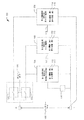
図1は、全体として100で示したバッテリーセル充電均等化システムの第1の特定の実施形態の図である。システム100は、正極端子および負極端子を有するバッテリーセル102を含むか、または、これに結合されている。バッテリーセル102は、複数セルバッテリーのうちの1つのセルであってもよい。例えば、バッテリーセル102は、所望の出力電圧を負荷に与えるために(図1には示していない)1つ以上の他のバッテリーセルに直列に結合されていてもよい。
FIG. 1 is a diagram of a first particular embodiment of a battery cell charge equalization system, indicated generally at 100. The
システム100は、複数セルバッテリーのセル間のバッテリーセル充電均等化を促進するために1つ以上の均等化回路を含んでいてもよい。例えば、均等化回路は、第1回路構成104、第2回路構成105、第3回路構成106またはこれらのいかなる組み合わせを含んでいてもよい。図1において、回路構成104〜106は機能ブロックとして示されているが、回路構成104〜106は、さまざまな形状因子または実施構成で提供されてもよい。例えば、回路構成104〜106は、バッテリーセル102に個別にまたは一体として結合可能な1つ以上のモジュール(すなわち、個別パッケージ部品)として提供されてもよい。別の実施例において、回路構成104〜106は、バッテリーセル102に結合可能な1枚以上の回路基板として提供されてもよい。別の実施例において、回路構成104〜106は、複数セルバッテリーの構成部品として複数セルバッテリー内に提供されてもよい。
ある特定の実施形態において、第1回路構成104は、監視および分路回路として機能してもよい。すなわち、第1回路構成104は、バッテリーセル102の電圧を監視してもよく、かつ、検出されたセル電圧がある特定の電圧閾値を満たすと、バッテリーセル102を通らないよう充電電流の少なくとも一部を迂回させてもよい。例示的な実施形態において、第1回路構成104は、第1電圧閾値110および第2電圧閾値111を有していてもよい。第2電圧閾値111は、第1電圧閾値110と異なっていてもよい。例えば、第2電圧閾値111は、第1電圧閾値110より低くてもよい。第1電圧閾値110と第2電圧閾値111とのこの差異により、第1回路構成104の不快な切り替わりを低減可能なヒステリシスがもたらされる。
In certain embodiments, the first circuit configuration 104 may function as a monitoring and shunt circuit. That is, the first circuit configuration 104 may monitor the voltage of the battery cell 102, and if the detected cell voltage satisfies a certain voltage threshold, at least one of the charging currents is prevented from passing through the battery cell 102. The part may be bypassed. In the exemplary embodiment, the first circuitry 104 may have a
例えば、バッテリーセル102の電圧が第1電圧閾値110を満たす(例えば、第1電圧閾値110より大きいか、または、第1電圧閾値110以上である)とき、充電電流の一部を分路116へと送ってもよい。これにより、バッテリーセル102へ印加される充電電流の量を低減し、組電池のその他のバッテリーセルがバッテリーセル102の充電状態(SOC)に追いつくことができる。例えば、バッテリーセル102を通らないように充電電流を迂回させることにより、バッテリーセル102のSOCの増加速度が弱まる可能性がある。より低いSOCを有し、かつ、完全充電電流を受け続けるその他のバッテリーセル(すなわち、充電電流は、これらのより低い(loser)SOCのバッテリーセルを通らないように迂回はされない)は、より高速に充電される。したがって、より低いSOCのバッテリーセルのSOCは、バッテリーセル102のSOCに追いつくことができる。
For example, when the voltage of the battery cell 102 satisfies the first voltage threshold 110 (eg, greater than the
充電電流の一部を分路116へ送ると、バッテリーセル102の電流が幾分低下することがある。バッテリーセル102の電圧のそのような低下により、第1回路構成104が分路116を切断する(すなわち、バッテリーセル102に完全充電電流を印加する)ようになる可能性を低減するために、第1回路構成104は、第2閾値111を用いて、分路116の非活性化を制御してもよい。すなわち、(第1電圧閾値110がもはや満たされていなくとも)第2閾値111が満たされている間は、充電電流の一部は、分路116へ送られてもよい。例示すると、ある特定の実施形態について、第1電圧閾値110は、約4.05Vであってもよく、第2電圧閾値111は約4.00Vであってもよい。本実施形態において、分路116は、バッテリーセル102の電圧が4.05Vに達すると活性化されてもよい。また、バッテリーセル102の電圧が4.05Vに達すると、第2閾値111は、活性化される。したがって、分路116は、バッテリーセル102の電圧が4.00Vより低くまで低下しないかぎりは、活性化状態に保たれてもよい。ある特定の実施形態において、分路116が活性化されていると、約C/500(ここで、Cは、典型的にアンペア時間またはミリアンペア時間で測定されるセルの容量を指す)の充電は、バッテリーセル102を通らないよう分流させられ、かつ、分路116の損失の大きい要素において放散されてもよい。第1回路構成104は、第1バッテリーセル102の電圧が第2電圧閾値111を満たさなくなったことに応答して、バッテリーセル102を迂回するよう(例えば、分路116へと)充電電流の一部を送らなくなってもよい。例えば、バッテリーセル102の電圧が(例えば、組電池の使用または保存中に)第2電圧閾値を満たさなくなった後で、第1電圧閾値110は、再度活性化され、第2電圧閾値111は、非活性化される。
Sending a portion of the charging current to shunt 116 may reduce the current in battery cell 102 somewhat. In order to reduce the likelihood that such a decrease in the voltage of the battery cell 102 will cause the first circuit arrangement 104 to disconnect the shunt 116 (ie, apply a full charge current to the battery cell 102), The single circuit configuration 104 may control the deactivation of the shunt 116 using the second threshold 111. That is, a portion of the charging current may be sent to the shunt 116 while the second threshold 111 is met (even if the
ある特定の実施形態において、第2回路構成105は、監視回路として機能してもよい。すなわち、第2回路構成105は、電圧がある特定の電圧閾値を満たすと、バッテリーセル102の電圧に基づいて監視出力117を生成してもよい。例示的な実施形態において、第2回路構成105は、第3電圧閾値112および第4電圧閾値113を有してもよい。第4電圧閾値113は、第3電圧閾値112と異なっていてもよい。例えば、第4電圧閾値113は、第3電圧閾値112より低くてもよい。第3電圧閾値112と第4電圧閾値113とのこの差異により、監視出力117の不快な切り替わりを低減可能なヒステリシスがもたらされる。
In certain embodiments, the second circuit configuration 105 may function as a monitoring circuit. That is, the second circuit configuration 105 may generate the
例えば、バッテリーセル102の電圧が第3電圧閾値112を満たす(例えば、第3電圧閾値112より大きいか、または、第3電圧閾値112以上である)とき、監視出力117が生成されて、バッテリーセル102が完全に充電されていることを示してもよい。監視出力117は、監視出力117が受信されたとき、または、バッテリーセルが完全に充電されていることを示す所定の数のバッテリーセルに関連付けられた回路構成からの出力といったその他の条件に応答して、組電池の充電を中断する(例えば、充電電流を中断する)ことができる監視システム(図示せず)に提供されてもよい。
For example, when the voltage of the battery cell 102 meets the third voltage threshold 112 (eg, greater than the
監視出力117が生成されると、充電電流の一部は、監視出力117を提供するために、バッテリーセル102を通らないよう迂回させられる。したがって、バッテリーセル102の電圧は、監視出力117が生成されていることに応答して幾分低下することがある。バッテリーセル102の電圧のそのような低下により監視出力117が切断される可能性を低減するために、第2回路構成105は、第4閾値113を用いて、監視出力117の非活性化を制御してもよい。すなわち、監視出力117は、第4閾値113が満たされている間、生成される。例示すると、ある特定の実施形態について、第3電圧閾値112は約4.10Vであってもよく、第4電圧閾値113は約4.05Vであってもよい。本実施形態において、監視出力117は、バッテリーセル102の電圧が4.10Vに達すると、活性化されてもよい。また、バッテリーセル102の電圧が4.10Vに達すると、第4閾値113が活性化されてもよい。したがって、監視出力117は、バッテリーセル102の電圧が4.05Vより下まで低下しないかぎりは、活性化状態を保っていてもよい。
When the
ある特定の実施形態において、第3回路構成106は、過充電監視回路として機能してもよい。すなわち、第3回路構成106は、電圧がある特定の電圧閾値を満たすとき、バッテリーセル102の電圧に基づいて、過充電出力118などの第2監視出力を生成してもよい。
In certain embodiments, the third circuit configuration 106 may function as an overcharge monitoring circuit. That is, the third circuit configuration 106 may generate a second monitoring output such as the
例示的な実施形態において、第3回路構成106は、第5電圧閾値114および第6電圧閾値115を有してもよい。第6電圧閾値115は、第5電圧閾値114が満たされたことに応答して、設定または活性化されてもよい。第6電圧閾値115は、第5電圧閾値114と異なっていてもよい。例えば、第6電圧閾値115は、第5電圧閾値114より低くてもよい。第5電圧閾値114と第6電圧閾値115とのこの差異により、過充電出力118の不快な切り替わりを低減可能なヒステリシスがもたらされる。
In the exemplary embodiment, the third circuitry 106 may have a fifth voltage threshold 114 and a sixth voltage threshold 115. The sixth voltage threshold 115 may be set or activated in response to the fifth voltage threshold 114 being met. The sixth voltage threshold value 115 may be different from the fifth voltage threshold value 114. For example, the sixth voltage threshold 115 may be lower than the fifth voltage threshold 114. This difference between the fifth voltage threshold 114 and the sixth voltage threshold 115 provides hysteresis that can reduce unpleasant switching of the
例えば、バッテリーセル102の電圧が第5電圧閾値114を満たす(例えば、第5電圧閾値114より大きいか、または、第5電圧閾値114以上である)とき、過充電出力118が生成されて、バッテリーセル102が過充電されているか、または、過充電される危険性があることを示してもよい。過充電出力118は、過充電出力118が受信されたとき、または、組電池のある数のバッテリーセルに関連付けられた回路構成からの過充電出力の受信といったその他の条件に応答して、組電池の充電を中断することができる監視システム(図示せず)に提供されてもよい。
For example, when the voltage of the battery cell 102 meets the fifth voltage threshold 114 (eg, greater than the fifth voltage threshold 114 or greater than or equal to the fifth voltage threshold 114), an
過充電出力118が生成されると、充電電流の一部は、過充電出力118を提供するために、バッテリーセル102を通らないよう迂回させられる。したがって、バッテリーセル102の電圧は、過充電出力118が生成されていることに応答して幾分低下することがある。バッテリーセル102の電圧のそのような低下により過充電出力118が切断される可能性を低減するために、第3回路構成106は、第6閾値115を用いて、過充電出力118の非活性化を制御してもよい。例示すると、ある特定の実施形態について、第5電圧閾値114は約4.30Vであってもよく、第6電圧閾値115は約4.10Vであってもよい。本実施形態において、過充電出力118は、バッテリーセル102の電圧が4.30Vに達すると、活性化されてもよい。また、バッテリーセル102の電圧が4.30Vに達すると、第6閾値115が活性化されてもよい。したがって、過充電出力118は、バッテリーセル102の電圧が4.10Vより下まで低下しないかぎりは、活性化状態を保っていてもよい。
When the
システム100はまた、第1スイッチ122および第2スイッチ124といった1つ以上のスイッチを含んでいてもよい。第1スイッチ122は、組電池の充電の完了後、第1回路構成104および第2回路構成105を介してバッテリーセル102の放電を低減するよう動作可能であってもよい。第2スイッチ124は、組電池の充電の終了後、第3回路構成106を介してバッテリーセル102の放電を低減するよう動作可能であってもよい。スイッチ122および124は、バッテリーセル102の自己放電率より小さいオフ(すなわち、オープン)リーク電流を有していてもよい。例えば、あるリチウムイオンバッテリーセルでは、自己放電率は、約C/100000であってもよい。したがって、スイッチ122および124は、C/100000より小さいオフリーク電流を有していてもよい。オン/オフスイッチ制御126は、(スイッチ122および124を閉鎖することにより)システム100への電源投入を可能として、バッテリーセル102からシステム100の回路要素へと電源を供給してもよい。ある特定の実施形態において、第2スイッチ124は、第3回路構成106への電力供給に用いてもよく、かつ、第1スイッチ122は、第1回路構成104および第2回路構成105への電力供給に用いてもよい。
バッテリーセル102の充電中、バッテリーセル102は、回路構成104〜106に取り付けられ、かつ、スイッチ122および124は閉鎖されている。バッテリーセル102の電圧が第1電圧閾値110を満たすと、第1回路構成104は、バッテリーセル102を通らないように充電電流を分路116へと導く。ある特定の実施形態において、分路116は、およそC/500の放電電流をバッテリーセル102から逃がす。また、バッテリーセル102の電圧が第1電圧閾値110を満たしたことに応答して、第1回路構成104は、第2電圧閾値111を設定または活性化して、分路116の不快なトリップを回避する。例示すると、第1電圧閾値110が4.05Vのとき、第2電圧閾値111は、0.05Vの閾値ヒステリシスを提供するために約4.00Vであってもよい。
During charging of battery cell 102, battery cell 102 is attached to circuitry 104-106 and
バッテリーセル102は、充電電流に付随しているので、バッテリーセル102の電圧は、分路116が活性化されている間でも、引き続き上昇する。バッテリーセル102の電圧は、第3電圧閾値112が満たされるまで上昇してもよい。第3電圧閾値112が満たされると、監視出力117は、活性化されてもよい。監視出力117は、バッテリーセル102のSOCがほぼ完全に近いことを示してもよい。監視出力117の活性化は、組電池に結合されている充電器に充電を低減または停止するよう信号を送ってもよい。また、バッテリーセル102の電圧が第3電圧閾値112を満たしたことに応答して、第2回路構成105は、第4電圧閾値113を設定または活性化して、監視出力117の不快なトリップを回避する。例示すると、第3電圧閾値112が4.10Vのとき、第4電圧閾値113は、0.05Vの閾値ヒステリシスを提供するために約4.05Vであってもよい。
Since the battery cell 102 is associated with the charging current, the voltage of the battery cell 102 continues to rise even while the shunt 116 is activated. The voltage of the battery cell 102 may increase until the
バッテリーセル102への充電電流が監視出力117に応答しないとき、第3回路構成106は、バッテリーセル102が有害な充電状態に近づいている(例えば、過充電状態に近づいている)ことを示すための保護監視装置として作用してもよい。例示すると、第5電圧閾値114が満たされると、過充電出力118は活性化してもよい。過充電出力118は、バッテリーセル102のSOCが有害な状態にあるか、または、これに近づいていることを示してもよい。過充電出力118の活性化は、充電器に組電池保護手順を開始するよう、例えば、充電器から組電池を取り外すよう信号を送ってもよい。また、バッテリーセル102の電圧が第5電圧閾値114を満たしたことに応答して、第3回路構成106は、第6電圧閾値115を設定または活性化して、過充電出力118の不快なトリップを回避する。例示すると、第5電圧閾値114が4.30Vのとき、第6電圧閾値115は、0.2Vの閾値ヒステリシスを提供するために約4.10Vであってもよい。
When the charging current to the battery cell 102 does not respond to the
活性化されていないとき(例えば、組電池が保存されている間)バッテリーセル充電均等化システム100は、バッテリーセル102の自己放電率より小さい電流を流してもよい。例えば、バッテリーセルの自己放電率は、バッテリーセルが完全に放電される2.8Vから3.0Vの範囲において約C/100000であってもよい。バッテリーセル充電均等化システム100が活性化されているとき(例えば、組電池の充電中)、バッテリーセル充電均等化システム100は、最大予測バッテリーセル動作電圧(例えば、いくつかの実施形態では、約4.1V)においておよそC/500の電流を流してもよい。ある特定の実施形態において、バッテリーセル充電均等化システム100の最大通電能力は、約C/500であり、これは、50Ahのバッテリーセルに対する約100mAおよび13Ahのバッテリーセルに対する約26mAに対応する。約C/500の電流に基づく4.1Vにおける最大ワット損は、50Ahのバッテリーセルに対して約410mWかつ13Ahのバッテリーセルに対して約107mWであってもよい。バッテリーセル充電均等化システム100は、組電池の動作温度範囲を通じて動作可能であってもよい。例えば、バッテリーセル充電均等化システム100は、−10°C以上50°Cまでの温度範囲にわたって動作可能であってもよく、この範囲は、約10°Cの余裕を有するリチウムイオンバッテリーセルの典型的な最大動作温度範囲を包含する。
When not activated (for example, while the battery pack is stored), the battery cell
図2は、組電池システムのある特定の実施形態の図である。図2は、直列に結合された複数のバッテリーセル206〜209を有する組電池202を示している。ある特定の実施形態において、組電池202は、リチウムイオン電池である。その他の実施形態では、組電池202は、鉛酸蓄電池、ニッケルカドミウム電池、ニッケル水素電池、リチウムイオンポリマー電池などの別の種類の電池、または、別の種類の充電式電池である。また、図2では4つのバッテリーセル206〜209を有する組電池202を示しているが、組電池202は、特定の実施構成によってはより多くのまたは少ないバッテリーセルを有していてもよい。
FIG. 2 is a diagram of a particular embodiment of an assembled battery system. FIG. 2 shows an assembled
図2において、組電池202は、正極端子205および負極端子204を介して負荷210に結合されている。負荷210は、組電池202を用いて電力供給されるいかなる装置またはシステムであってもよい。例えば、負荷210は、電子装置またはツールといった電池式携帯機器を含んでもよい。別の実施例において、負荷210は、衛星または電気もしくはハイブリッド航空機または自動車などの輸送手段の動力装置やその他のシステムを含んでもよい。さらに別の実施例において、負荷210は、分配用の電力の保存のために組電池202を用いる配電システムを含んでもよい。
In FIG. 2, the assembled
組電池202は、充電器212に結合されていてもよい。充電器212は、充電電流を組電池202へ供給して、バッテリーセル206〜209を再充電してもよい。上で説明したように、バッテリーセル206〜209の不均等な充電は、組電池202の性能を低下させる可能性があるか、または、組電池202の耐用寿命を短縮する可能性がある。したがって、バッテリーセル206〜209は、バッテリーセル充電均等化システム224に結合されていてもよい。バッテリーセル充電均等化システム224は、バッテリーセル206〜209の各々に結合されているバッテリーセル充電均等化回路を含んでもよい。例えば、第1バッテリーセル充電均等化回路220は、第1バッテリーセル206に結合されていてもよく、第2バッテリーセル充電均等化回路221は、第2バッテリーセル207に結合されていてもよく、第3バッテリーセル充電均等化回路222は、第3バッテリーセル208に結合されていてもよく、かつ、第4バッテリーセル充電均等化回路223は、第4バッテリーセル209に結合されていてもよい。
The assembled
バッテリーセル充電均等化回路220〜223は、受動的なバッテリーセル充電均等化、バッテリーセル充電状態(SOC)の監視およびバッテリーセル過充電の監視といったさまざまな機能を実施するための回路構成を含んでいてもよい。例えば、バッテリーセル充電均等化回路220〜223は、バッテリーセル206〜209間のSOCの同等化または均等化を促進するための第1回路構成230〜233を含んでいてもよい。例示すると、第1回路構成230〜233の各回路は、図1の第1回路構成104および分路116を含んでいてもよい。例示的な実施形態において、対応するバッテリーセルの電圧が第1電圧閾値(例えば、4.05V)に達すると、第1回路構成230〜233は、対応するバッテリーセルを通らないように充電器212から受けた充電電流を迂回させてもよい。第1回路構成230〜233はまた、第1電圧閾値が満たされたことに応答して、第2電圧閾値(例えば、4.00V)を活性化してもよい。例えば、充電中に、第1バッテリーセル206が第1電圧閾値に達すると、第1バッテリー充電均等化回路220の第1回路構成230により第1バッテリーセル206を通らないように充電電流の少なくとも一部を分路してもよい。充電電流が依然としてその他のバッテリーセル207〜209に印加されている間に、第1バッテリーセル206を通らないように充電電流の少なくとも一部を迂回させることにより、その他のバッテリーセル207〜209が第1バッテリーセル206のSOCに追いつくことができてもよい。
Battery cell charge equalization circuits 220-223 include circuitry for performing various functions such as passive battery cell charge equalization, battery cell charge state (SOC) monitoring and battery cell overcharge monitoring. May be. For example, the battery cell
バッテリーセル充電均等化回路220〜223はまた、バッテリーセル206〜209のSOCの監視を促進するための第2回路構成240〜243を含んでいてもよい。例示すると、第2回路構成240〜243の各回路は、図1の第2回路構成105を含んでいてもよい。例示的な実施形態において、第2回路構成240〜243の各回路は、関連付けられたバッテリーセルの電圧が第3電圧閾値(例えば、4.10V)に達すると、関連付けられたバッテリーセルが目標SOCに達したこと(例えば、対応するバッテリーセルが実質的に完全に充電されていること)を示す出力260〜263を生成してもよい。第2回路構成240〜243はまた、第3電圧閾値が満たされたことに応答して、第4電圧閾値(例えば、4.05V)を活性化してもよい。例えば、充電中に、第4バッテリーセル209が第3電圧閾値に達すると、出力263は、充電状況信号を提供するよう活性化されてもよい。充電状況信号は、充電器212に充電電流を低減または切断させることのできる監視または制御システムへ送られてもよい。
Battery cell charge equalization circuits 220-223 may also include second circuit configurations 240-243 for facilitating the monitoring of the SOC of battery cells 206-209. To illustrate, each circuit of the
バッテリーセル充電均等化回路220〜223は、バッテリーセル206〜209の過充電監視を促進するための第3回路構成250〜253を含んでいてもよい。例示すると、第3回路構成250〜253の各回路は、図1の第3回路構成106を含んでいてもよい。例示的な実施形態において、第3回路構成250〜253は、関連付けられたバッテリーセルの電圧が第5電圧閾値(例えば、4.30V)に達すると、関連付けられたバッテリーセルが有害なSOCにあるか、または、これに近づいていること(例えば、関連付けられたバッテリーセルが過充電されているか、または、過充電状態に近づいていること)を示す過充電出力265〜268を生成してもよい。第3回路構成250〜253はまた、第5電圧閾値が満たされたことに応答して、第6電圧閾値(例えば、4.10V)を活性化してもよい。例えば、充電中に、第4バッテリーセル209が第5電圧閾値に達すると、過充電出力268は、過充電信号を提供するよう活性化されてもよい。過充電信号は、バッテリーセル206〜209の有害な過充電を予防する対策を講じることのできる監視または制御システムへ送られてもよい。例えば、監視または制御システムは、充電器212を遮断するか、または、組電池202を充電器212から電気的に切断してもよい。
Battery cell charge equalization circuits 220-223 may include third circuit configurations 250-253 for facilitating overcharge monitoring of battery cells 206-209. Illustratively, each circuit of the third circuit configurations 250-253 may include the third circuit configuration 106 of FIG. In an exemplary embodiment, the third circuitry 250-253 may cause the associated battery cell to be in a detrimental SOC when the associated battery cell voltage reaches a fifth voltage threshold (eg, 4.30V). Or may generate overcharge outputs 265-268 indicating that this is approaching (eg, the associated battery cell is overcharged or is approaching an overcharged state). . The third circuitry 250-253 may also activate a sixth voltage threshold (eg, 4.10V) in response to the fifth voltage threshold being met. For example, during charging, when the fourth battery cell 209 reaches a fifth voltage threshold, the
ある1つのバッテリーセル充電均等化回路、例えば、第1バッテリーセル充電均等化回路220に対して用いられる閾値は、その他のバッテリーセル充電均等化回路、例えば、第2、第3および第4バッテリーセル充電均等化回路221〜223により用いられる閾値と同じであっても、異なっていてもよい。例えば、組電池202の充電中に、第1バッテリーセル充電均等化回路220の第1回路構成230は、第1バッテリーセル206を通らないよう充電電流の一部を導き、かつ、第2閾値を活性化するために第1閾値を用いてもよい。第1バッテリーセル充電均等化回路220の第2回路構成240は、監視出力を活性化し、かつ、第4閾値を活性化するために第3閾値を用いてもよい。第1バッテリーセル充電均等化回路220の第3回路構成250は、過充電出力を活性化し、かつ、第6閾値を活性化するために第5閾値を用いてもよい。同時に、すなわち、組電池202の同じ充電サイクル中に、第2バッテリーセル充電均等化回路221の第1回路構成231は、第2バッテリーセル207を通らないよう充電電流の一部を導き、かつ、(第2閾値とは異なっていても、同じであってもよい)第8閾値を活性化するために(第1閾値とは異なっていても、同じであってもよい)第7閾値を用いてもよい。第2バッテリーセル充電均等化回路221の第2回路構成241は、監視出力を活性化し、かつ、(第4閾値とは異なっていても、同じであってもよい)第10閾値を活性化するために(第3閾値とは異なっていても、同じであってもよい)第9閾値を用いてもよい。第2バッテリーセル充電均等化回路221の第3回路構成251は、過充電出力を活性化し、かつ、(第6閾値とは異なっていても、同じであってもよい)第12閾値を活性化するために(第5閾値とは異なっていても、同じであってもよい)第11閾値を用いてもよい。同様に、第3バッテリーセル充電均等化回路222および第4バッテリーセル充電均等化回路223は、第1バッテリーセル充電均等化回路220および第2バッテリーセル充電均等化回路221により用いられる閾値と同じであるか、または、異なっている閾値を用いてもよい。
The threshold used for one battery cell charge equalization circuit, eg, the first battery cell
バッテリーセル充電均等化回路220〜223はまた、スイッチ280〜283およびスイッチ285〜288を含んでいてもよい。スイッチ280〜283およびスイッチ285〜288は、組電池202の充電中は閉鎖されて、バッテリーセル充電均等化回路220〜223に電力供給してもよい。スイッチ280〜283およびスイッチ285〜288は、組電池202の保存または使用中は開放されて、バッテリーセル充電均等化回路220〜223が組電池202およびバッテリーセル206〜209の自己放電率を上昇させないように、バッテリーセル充電均等化回路220〜223を通じる電流の流れを低減してもよい。ある特定の実施形態において、スイッチ280〜283およびスイッチ285〜288は、バッテリーセル充電均等化システム224のリターン入力270およびオン/オフ入力272を介して制御してもよい。
Battery cell charge equalization circuits 220-223 may also include switches 280-283 and switches 285-288. The
図2は、電圧閾値の特定の値を示しているが、電圧閾値は、他の実施形態において他の値を有する可能性もある。例えば、ある特定のリチウムイオン電池の完全充電電圧は、約4.10Vであってもよい一方で、他の種類の電池または他のリチウムイオン電池は、他の完全充電電圧を有していてもよい。さらに、電池寿命の延長などの特定の使用に対して、より低い電圧を完全充電電圧として指定してもよい。例示すると、ある特定の用途に対して、リチウムイオン電池の完全充電電圧は、リチウムイオン電池の寿命を延長するために約3.92Vに設定されてもよい。その他の閾値もまた、(電池の作成に用いられる特定の材料を含む)電池の種類、電池が用いられる予定の用途(例えば、負荷210の特定の種類または性質、組電池202の動作環境など)、組電池202が晒されるその他の動作制約(例えば、規制の制約またはその他の規格)、充電器212、組電池202、負荷210またはこれらのあらゆる組み合わせのその他の特徴によって選択されてもよい。
Although FIG. 2 shows specific values for the voltage threshold, the voltage threshold may have other values in other embodiments. For example, the full charge voltage of a particular lithium ion battery may be about 4.10V, while other types of batteries or other lithium ion batteries may have other full charge voltages. Good. In addition, a lower voltage may be designated as the full charge voltage for certain uses, such as extending battery life. Illustratively, for certain applications, the full charge voltage of a lithium ion battery may be set to about 3.92V to extend the life of the lithium ion battery. Other thresholds may also include the type of battery (including the specific material used to make the battery), the application for which the battery will be used (eg, the specific type or nature of the
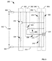
図3は、300で示されたバッテリーセル充電均等化回路構成の第1の特定の実施形態の模式図である。ある特定の実施形態において、回路構成300は、バッテリーセル充電均等化を促進するために用いられてもよい。例えば、回路構成300は、図1の第1回路構成104として用いられてもよい。図3において、回路構成300は、バッテリーセル302と結合されているものとして示されている。バッテリーセル302は、他のバッテリーセルと直列接続されて、バッテリーパックを形成してもよい正極端子304および負極端子306を含む。回路構成300の入力は、バッテリーセル302の正極端子304に結合されていてもよく、かつ、リターン312は、バッテリーセル302の負極端子306に結合されていてもよい。図示されていないその他の構成要素が存在することもある。例えば、回路構成300は、図1のスイッチ124などのスイッチを介してバッテリーセル302と結合していてもよい。回路構成300のいずれの特定の部分が説明されているのかを明確にするために、ここで「回線経路」と呼ばれる回路構成300の個々の部分を、図3における破線の枠を用いて示している。破線の枠は、説明を簡略化および明確化するために用いられており、回路構成300の限定として解釈されるべきではない。
FIG. 3 is a schematic diagram of a first particular embodiment of a battery cell charge equalization circuit configuration indicated at 300. In certain embodiments, the
回路構成300は、分圧回路を形成する第1抵抗素子314(例えば、第1抵抗器)および第2抵抗素子316(例えば、第2抵抗器)を含む。分圧回路の分圧回路出力318は、電圧基準装置320の基準電圧入力に結合されている。ある特定の実施形態において、電圧基準装置320は、テキサスインスツルメンツ社から入手可能なTL1431精密プログラマブル基準などの高精度電圧基準を含む。図3に示す特定の実施形態では、ツェナーダイオードを示すのに一般に用いられる記号と類似の記号を用いて電圧基準装置320を示しているが、電圧基準装置320は、単なるツェナーダイオードではないことに注目されたい。むしろ、電圧基準装置320は、入力基準電圧に応答して出力電圧を提供する高精度かつ安定な(例えば、動作温度範囲にわたって安定な)電圧基準である。図6は、図3の電圧基準装置320として用いることができる電圧基準装置のある特定の実施形態の等価模式図を示している。ある特定の実施形態において、電圧基準装置320は、2.5Vのバンドギャップ基準を含む。
The
第1抵抗素子314および第2抵抗素子316の抵抗(または、第1抵抗素子314および第2抵抗素子316が純粋な抵抗でないときは、インピーダンス)は、第1電圧閾値が満たされると、分圧回路出力318が電圧基準装置320に電源を投入するように、選択される。すなわち、電流が分圧回路を含む初めの回線経路390を通じて流れるとき、かつ、入力310とリターン312との間の電圧が第1電圧閾値を満たすとき、分圧回路出力318は、電圧基準装置320の電源投入に十分である。例えば、電圧基準装置320が2.5Vバンドギャップ基準であるとき、分圧回路出力318は、第1電圧閾値が満たされると2.5V以上であってもよい。
The resistance of the
電圧基準装置320に電源が投入されると、第3抵抗素子322および電圧基準装置320を含む第1回線経路391を通じて電流が流れる。第1回線経路391における電流の流れに応答して、(トランジスタなどの)第1スイッチング素子326に電源が投入されてもよい。例えば、第1回線経路391を通る電流の流れは、トランジスタのベース(例えば、第1スイッチング素子326)に電流を印加してもよく、これにより、第1スイッチング素子326および第4抵抗素子328を含む第2回線経路392を活性化する(すなわち、第2回線経路392を通じて電流が流れるようにする)ことができる。
When the
第2回線経路392は、分圧回路において第4抵抗素子328が第1抵抗素子314と並列であるように配置してもよい。したがって、第2回線経路392が活性化されると、分圧回路の分圧回路率が修正され(効率的に第2分圧回路を形成す)る。第4抵抗素子328の抵抗(またはインピーダンス)は、回路構成300の第2電圧閾値を実施するか、そうでなければ、これを設定するよう選択されてもよい。例示すると、第4抵抗素子328の抵抗は、入力310とリターン312との間の電圧が第2電圧閾値を満たすと、分圧回路出力318が電圧基準装置320の活性化電圧より低くまで低下するように、選択されてもよい。
The
例えば、図1を参照して実施例として説明した特定の電圧閾値を用いて、第1電圧閾値は、4.05Vであってもよく、第2電圧閾値は、4.00Vであってもよい。さらに、電圧基準装置320は、2.5Vの活性化電圧を有していてもよい。すなわち、電圧基準装置320は、分圧回路出力318において2.5Vの電圧が存在するとき、電源が投入されてもよい。本実施例において、第1抵抗素子314および第2抵抗素子316の値は、第1分圧回路率を提供するよう選択されてもよい。第1分圧回路率は、入力310とリターン312との間の電圧が4.05V(第1電圧閾値)であるとき、分圧回路出力318を2.5Vとするよう選択されてもよい。したがって、第1電圧閾値が満たされると、電圧基準装置320は、電源投入され、かつ、電流を第1トランジスタのベース(すなわち、第1スイッチング素子326)へと流してもよい。これに応答して、第1トランジスタは、第4抵抗素子328を通って電流を流して、第2分圧回路率を有するよう分圧回路を修正してもよい。第2分圧回路率は、入力310とリターン312との間の電圧が4.00Vより低くまで低下すると、分圧回路出力318が2.5Vより低くまで低下する(すなわち、電圧基準装置320の電源を切断する)ように、選択される。
For example, using the specific voltage threshold described in the embodiment with reference to FIG. 1, the first voltage threshold may be 4.05V, and the second voltage threshold may be 4.00V. . Further, the
電流が第1回線経路391を通って流れると、第2スイッチング素子332もまた活性化されてもよい。例えば、第2トランジスタのベース(例えば、第2スイッチング素子332)に電流を印加して、第3回線経路393を活性化してもよい。第3回線経路393は、バッテリーセル302を通らないよう充電電流の少なくとも一部を迂回させてもよい。例えば、第3回線経路393は、充電電流の一部を(図1の分路116のような)損失の大きい回路素子334へ送ってもよい。したがって、バッテリーセル302の充電速度を低下させて、他のバッテリーセル(図示せず)がバッテリーセル302の充電状態に追いつけるようにしてもよい。また、回路構成300は、自らの動作により自動的に第1電圧閾値と第2電圧閾値との間で切り替わるので、回路構成300は、回路構成300の不快なトリッピングを低減することができる閾値ヒステリシスをもたらす。
As current flows through the
ある特定の実施形態において、バッテリーセル302の電圧が第2電圧閾値を満たさなくなった後(例えば、組電池の使用または保存中)、第1電圧閾値は再度活性化され、かつ、第2電圧閾値は非活性化される。例えば、電圧が第2電圧閾値より低くまで低下すると、分圧回路出力318が電圧基準装置320の最低電圧入力より低くまで低下する結果として、電圧基準装置320は、電源を切断してもよい。電圧基準装置320の電源が切断されると、第1回線経路391における電流の流れが停止する可能性がある。したがって、第1スイッチング素子326は、非活性化してもよく、かつ、第2回線経路392における電流の流れが停止する可能性があり、これにより、分圧回路から第4抵抗素子328が取り除かれる。したがって、分圧回路は、第1抵抗素子314および第2抵抗素子316を含むが、第4抵抗素子328は含まないように再設定される。また、第1回線経路391における電流の流れの停止に応答して、第2スイッチング素子332は非活性化してもよく、かつ、第3回線経路393における電流の流れは停止してもよい。
In certain embodiments, after the voltage of the
図4は、バッテリーセル充電均等化回路構成の第2の特定の実施形態の模式図である。図4は、バッテリーセルのSOCまたは過充電監視を促進するために出力402が監視システムに結合されている状態の回路構成300を示している。図3および図4における同じ参照番号を有する要素は、図3を参照して説明したように機能する。図1および図2を参照して説明されているように、バッテリーセル302のSOCまたはバッテリーセル302の過充電状態を監視するために用いられる電圧閾値は、バッテリーセル充電均等化のために用いられる電圧閾値とは異なっていてもよい。したがって、分圧回路を形成する抵抗素子314、316および328の値は、特定の電圧閾値に基づいて選択されてもよい。
FIG. 4 is a schematic diagram of a second specific embodiment of a battery cell charge equalization circuit configuration. FIG. 4 shows a
電流が第2スイッチング素子332を通って第3回線経路を流れると、該電流は、出力402へ送られる。本実施形態において、抵抗素子404を用いてもよいが、損失の大きい分路は存在しない。出力402は、監視システムに提供されてもよい。
As current flows through the third line path through the
ある特定の実施形態において、アイソレーションシステムを用いて、監視システムから回路構成300を分離してもよい。例えば、光アイソレータ440を用いることができる。光アイソレータ440は、監視システムと回路構成300とが大きな電位、例えば、何百ボルトの電位により分離できるようにしてもよい。光アイソレータ440は、回路構成300の出力402および電源電圧450に基づいて出力信号452を生成してもよい。例示すると、光アイソレータ440は、光センサ素子454(例えば、感光性ダイオード)と出力402に応答する発光ダイオード(LED)442とを含んでいてもよい。LED442は、光センサ素子454により検出可能な光を発生させてもよい。LED442が出力402に応答して発光すると、光センサ素子454は、その光を検出して、出力信号452を発生させてもよい。したがって、回路構成300および監視システムは、互いからの電気的分離を保ったままで連通してもよい。
In certain embodiments, an isolation system may be used to separate the
図5は、バッテリーセル充電均等化方法のある特定の実施形態のフローチャートである。該方法は、図1〜図4に示した回路のうちの1つ以上を用いて実施可能である。 FIG. 5 is a flowchart of a specific embodiment of a battery cell charge equalization method. The method can be implemented using one or more of the circuits shown in FIGS.
ある特定の実施形態において、該方法は、502で、複数セルバッテリーのあるバッテリーセルに結合されたバッテリー充電均等化回路において充電電流を受けることを含む。該方法はまた、504において、バッテリーセルの電圧が第1電圧閾値を満たすとき、バッテリーセルを通らないよう充電電流の少なくとも一部を迂回させることを含んでもよい。例えば、506において、充電電流の少なくとも一部は、バッテリーセルを通らないよう充電電流の少なくとも一部を分路させるバイパス回線経路へ送ってもよい。別の実施例において、508で、充電電流の少なくとも一部を監視出力へ送ってもよい。 In certain embodiments, the method includes, at 502, receiving a charging current in a battery charge equalization circuit coupled to a battery cell of the multi-cell battery. The method may also include, at 504, diverting at least a portion of the charging current to not pass through the battery cell when the voltage of the battery cell meets the first voltage threshold. For example, at 506, at least a portion of the charging current may be sent to a bypass line path that shunts at least a portion of the charging current so that it does not pass through the battery cell. In another embodiment, at 508, at least a portion of the charging current may be sent to the monitoring output.
該方法はまた、510において、バッテリーセルの電圧が第1電圧閾値を満たしたことに応答して第2電圧閾値を設定することを含んでもよい。第2電圧閾値は、第1電圧閾値より低くてもよい。例えば、図1を参照して説明したように、第1電圧閾値は4.05Vであってもよく、かつ、第2電圧閾値は4.00Vであってもよい。図1を参照して説明した別の実施例において、第1電圧閾値は4.10Vであってもよく、かつ、第2電圧閾値は4.05Vであってもよい。図1を参照して説明したさらに別の実施例において、第1電圧閾値は4.30Vであってもよく、かつ、第2電圧閾値は4.10Vであってもよい。充電電流の少なくとも一部は、バッテリーセルの電圧が第2電圧閾値を満たしている間、バッテリーセルを通らないよう迂回させてもよい。 The method may also include, at 510, setting a second voltage threshold in response to the voltage of the battery cell meeting the first voltage threshold. The second voltage threshold may be lower than the first voltage threshold. For example, as described with reference to FIG. 1, the first voltage threshold value may be 4.05V, and the second voltage threshold value may be 4.00V. In another embodiment described with reference to FIG. 1, the first voltage threshold may be 4.10V and the second voltage threshold may be 4.05V. In yet another embodiment described with reference to FIG. 1, the first voltage threshold may be 4.30V and the second voltage threshold may be 4.10V. At least a portion of the charging current may be diverted from passing through the battery cell while the voltage of the battery cell meets the second voltage threshold.
例示的な実施形態において、第1および第2電圧閾値は、分圧回路を用いて実施されてもよい。例えば、分圧回路の出力は、電圧基準装置と結合されてもよい。電圧基準装置は、第1電圧閾値が満たされているとき、第1回線経路における電流の流れを可能としてもよい。第1回線経路における電流の流れにより、分圧回路の分圧回路率を修正してもよい。第2電圧閾値は、512において、分圧回路の分圧回路率を修正することにより設定してもよい。第1回線経路における電流の流れはまた、バッテリーセルを通らないよう充電電流の少なくとも一部を迂回させることを可能としてもよい。 In an exemplary embodiment, the first and second voltage thresholds may be implemented using a voltage divider circuit. For example, the output of the voltage divider circuit may be coupled to a voltage reference device. The voltage reference device may allow current flow in the first line path when the first voltage threshold is satisfied. The voltage dividing circuit ratio of the voltage dividing circuit may be corrected by the current flow in the first line path. The second voltage threshold may be set at 512 by modifying the voltage divider ratio of the voltage divider circuit. The current flow in the first line path may also allow at least a portion of the charging current to be diverted from passing through the battery cell.
ある特定の実施形態において、該方法は、514において、複数セルバッテリーを充電した後でスイッチを開放することを含んでもよい。スイッチを開放することにより、バッテリーセルの自己放電率より低い率までのバッテリーセル充電均等化回路を通じたバッテリーセルの放電が低減される可能性がある。 In certain embodiments, the method may include, at 514, opening the switch after charging the multi-cell battery. Opening the switch may reduce the discharge of the battery cell through the battery cell charge equalization circuit to a rate lower than the self-discharge rate of the battery cell.
ここに開示する特定の実施形態は、一般に入手可能な集積回路および個別部品を用いて、バッテリーセルの充電状態(SOC)の高速かつ信頼性の高い検出を可能とすると同時に、ノイズの多い監視用出力信号およびセル充電均等化分路回路に付随する不快感を減ずることができる。バッテリーセル充電均等化回路を通じたバッテリーセルの寄生放電を低減するために、スイッチを設けて、バッテリーセルからバッテリーセル充電均等化回路を分離してもよい。該スイッチはまた、「ホットメイト」の問題を低減することもある。バッテリーセル充電均等化回路は、容易に入手可能かつ丈夫であってもよい。ある用途では、バッテリーセル充電均等化回路は、例えば、宇宙における使用のために放射線硬化することができる。 Certain embodiments disclosed herein allow for fast and reliable detection of battery cell state of charge (SOC) using commonly available integrated circuits and discrete components while at the same time for noisy monitoring Discomfort associated with the output signal and the cell charge equalization shunt circuit can be reduced. In order to reduce the parasitic discharge of the battery cell through the battery cell charge equalization circuit, a switch may be provided to separate the battery cell charge equalization circuit from the battery cell. The switch may also reduce “hot mate” problems. The battery cell charge equalization circuit may be readily available and robust. In some applications, the battery cell charge equalization circuit can be radiation cured, for example, for use in space.
ここに開示するバッテリーセル充電均等化システムは、自己完結型とすることができる。すなわち、バッテリーセル充電均等化の実施に他の資源(例えば、コンピュータまたはソフトウェア)を必要としない。複数サイクルにわたってバッテリーセルを通らないよう充電電流を分路させることにより、完全に近く充電されているときに、より低いSOCのセルが追いつくことができる。また、バッテリーセル充電均等化システムは、特定の用途のためにカスタマイズすることができる。例えば、閾値および閾値ヒステリシスは、分圧回路要素の選択により、特定の組電池または用途のためにカスタマイズすることができる。 The battery cell charge equalization system disclosed herein can be self-contained. That is, no other resources (eg, a computer or software) are required to perform battery cell charge equalization. By shunting the charging current away from the battery cell for multiple cycles, the lower SOC cell can catch up when fully charged. Also, the battery cell charge equalization system can be customized for specific applications. For example, the threshold and threshold hysteresis can be customized for a specific battery pack or application by selection of voltage divider circuitry.
ある特定の実施形態において、ここに開示するバッテリーセル充電均等化システムにより用いられる閾値は、動的に調整可能であってもよい。例えば、図3を参照すると、閾値の設定に用いられる分圧回路を形成する抵抗素子314、316および328は、制御入力に応答する可変抵抗器であってもよい。したがって、監視または制御システムは、閾値の1つ以上を調整するよう1つ以上の抵抗素子314、316および328の抵抗を調整するために制御入力を提供してもよい。例えば、閾値の1つ以上を動的に調整して、変化する動作条件、1つ以上のセルのエージングまたは1つ以上のセルに対する損傷を補償してもよい。別の実施例において、組電池の最初の構成中に閾値の1つ以上を調整して、セル間の小さな製造または機能の差異を補償してもよい。例示すると、組電池の性能を微調整するために、セルを組み立てて組電池を形成した後で組電池の各セルに用いられる閾値を調整してもよい。
In certain embodiments, the threshold used by the battery cell charge equalization system disclosed herein may be dynamically adjustable. For example, referring to FIG. 3, the
ここに開示した実施形態の説明は、さまざまな実施形態の構造の一般的理解をもたらすよう意図されている。該説明は、ここに説明した構造または方法を利用する装置およびシステムの構成要素および特徴のすべての完全な記述となることを意図されていない。開示を検討すると、当業者にとって数多くの他の実施形態が明白かもしれない。その他の実施形態を利用し、かつ、該開示から導き出してもよく、その結果、開示の範囲を逸脱することなく構造的および論理的な代用や変更を行うことができる。例えば、図示されているのとは異なる順序で方法工程を行ってもよく、1つ以上の方法工程を省略してもよい。したがって、開示および図は、制限的というよりむしろ例示的なものと考えられるべきである。 The description of the embodiments disclosed herein is intended to provide a general understanding of the structure of the various embodiments. The description is not intended to be a complete description of all of the components and features of apparatus and systems that utilize the structures or methods described herein. Many other embodiments may be apparent to those of skill in the art upon reviewing the disclosure. Other embodiments may be utilized and derived from the disclosure, so that structural and logical substitutions and changes can be made without departing from the scope of the disclosure. For example, method steps may be performed in a different order than shown, and one or more method steps may be omitted. Accordingly, the disclosure and figures are to be regarded as illustrative rather than restrictive.
そのうえ、ここでは特定の実施形態を例示および記述したが、同じまたは類似の結果を達成するよう設計されたいかなる後続の配置構成を示した特定の実施形態の代わりに用いてもよいことは理解されたい。本開示は、さまざまな実施形態のあらゆるすべての後続の適合または変形例を包含するよう意図されている。上記実施形態の組み合わせおよびここに特定して説明していないその他の実施形態は、記述を検討すると、当業者にとって明白であろう。 Moreover, while specific embodiments have been illustrated and described herein, it is understood that any subsequent arrangement designed to achieve the same or similar results may be used in place of the specific embodiment shown. I want. This disclosure is intended to cover any and all subsequent adaptations or variations of various embodiments. Combinations of the above embodiments, and other embodiments not specifically described herein, will be apparent to those of skill in the art upon review of the description.
開示の要約は、それが請求項の範囲または意味の解釈または限定に用いられることはないという理解のもとで提出されている。これに加えて、前述の詳細な説明において、開示を整理する目的でさまざまな特徴をひとまとめにしたり、単一の実施形態において説明したりすることができる。本開示は、請求されている実施形態が各請求項にはっきりと記載されているより多くの特徴を必要とするという意図を反映するものとして解釈されるべきでない。むしろ、以下の請求項が反映しているように、請求されている主題は、開示されている実施形態のいずれかの特徴のすべてよりも少ない特徴に向けられていてもよい。
また、本願は以下に記載する態様を含む。
(態様1)
直列に結合されている複数のバッテリーセルを含む組電池と、
第1バッテリーセルの電圧を監視するための第1回路構成であって、組電池に充電電流が印加されると、第1バッテリーセルの電圧が第1電圧閾値を満たしたことに応答して、第1回路構成が、第1バッテリーセルを迂回するよう充電電流の少なくとも一部を送り、かつ、第1バッテリーセルの電圧が第1電圧閾値を満たしたことに応答して、第1回路構成が、第2電圧閾値を設定する、第1回路構成と、
第1バッテリーセルの電圧を監視するための第2回路構成であって、組電池に充電電流が印加されると、第1バッテリーセルの電圧が第3電圧閾値を満たしたことに応答して、第2回路構成が、監視出力を生成し、ここで、第3電圧閾値が第1電圧閾値より高い、第2回路構成と、
を含む組電池システム。
(態様2)
第1バッテリーセルの電圧が第3電圧閾値を満たしたことに応答して、第2回路構成が、第4電圧閾値を設定し、ここで、第4電圧閾値が第3電圧閾値より低く、かつ、第4電圧閾値が満たされている間に監視出力が生成される、態様1に記載のシステム。
(態様3)
第1バッテリーセルの電圧が第2電圧閾値を満たさなくなったことに応答して、第1回路構成が、第1バッテリーセルを迂回するよう充電電流の少なくとも一部を送ることを停止する、態様1に記載のシステム。
(態様4)
第1バッテリーセルの電圧が第2電圧閾値を満たさなくなった後に、第1電圧閾値が再度活性化され、かつ、第2電圧閾値が非活性化される、態様3に記載のシステム。
(態様5)
第1バッテリーセルの電圧を監視するための第3回路構成をさらに含み、組電池に充電電流が印加されると、第1バッテリーセルの電圧が第5電圧閾値を満たしたことに応答して、第3回路構成が、第2監視出力を生成し、ここで、第5電圧閾値が第3電圧閾値より高い、態様1に記載のシステム。
(態様6)
第1バッテリーセルに対する充電電流が、第2監視出力に応答して切断される、態様5に記載のシステム。
(態様7)
第1バッテリーセルの電圧が第5電圧閾値を満たしたことに応答して、第3回路構成が、第6電圧閾値を設定する、態様5に記載のシステム。
(態様8)
第1バッテリーセルと第1および第2回路構成との間に第1スイッチをさらに含み、第1スイッチが、組電池の充電が完了した後で第1および第2回路構成を介したバッテリーセルの放電を低減するよう動作可能である、態様1に記載のシステム。
(態様9)
第1バッテリーセルの電圧を監視するための第3回路構成であって、組電池に充電電流が印加されると、第1バッテリーセルの電圧が第5電圧閾値を満たしたことに応答して、第3回路構成が、第2監視出力を生成し、ここで、第5電圧閾値が第3電圧閾値より高い、第3回路構成と、
第1バッテリーセルと第3回路構成との間の第2スイッチであって、組電池の充電が完了した後で第3回路構成を介したバッテリーセルの放電を低減するよう動作可能である、第2スイッチと、
をさらに含む、態様8に記載のシステム。
(態様10)
第1バッテリーセルと直列に結合されている少なくとも1つの第2バッテリーセルと、
少なくとも1つの第2バッテリーセルと結合されており、第2バッテリーセルの電圧を監視するための第4回路構成であって、組電池に充電電流が印加されると、少なくとも1つの第2バッテリーセルの電圧が第7電圧閾値を満たしたことに応答して、第4回路構成が、少なくとも1つの第2バッテリーセルを迂回するよう充電電流の少なくとも一部を送り、かつ、少なくとも1つの第2バッテリーセルの電圧が第7電圧閾値を満たしたことに応答して、第4回路構成が、第8電圧閾値を設定する、第4回路構成と、
第2バッテリーセルの電圧を監視するための第5回路構成であって、組電池に充電電流が印加されると、少なくとも1つの第2バッテリーセルの電圧が第9電圧閾値を満たしたことに応答して、第5回路構成が、第3監視出力を生成し、ここで、第9電圧閾値が第7電圧閾値より高い、第5回路構成と、
をさらに含む、態様1に記載のシステム。
(態様11)
バッテリーセル充電均等化方法であって、
複数セルバッテリーのうちのあるバッテリーセルに結合されているバッテリー充電均等化回路において充電電流を受けることと、
バッテリーセルの電圧が第1電圧閾値を満たすと、バッテリーセルを通らないよう充電電流の少なくとも一部を迂回させることと、
バッテリーセルの電圧が第1電圧閾値を満たしたことに応答して、第2電圧閾値を設定することであって、ここで、第2電圧閾値が第1電圧閾値より低く、かつ、バッテリーセルの電圧が第2電圧閾値を満たしている間にバッテリーセルを通らないよう充電電流を送る、設定することと、
を含む、方法。
(態様12)
バッテリー充電均等化回路の分圧回路の分圧回路率を修正することにより、第2電圧閾値を設定する、態様11に記載の方法。
(態様13)
分圧回路の出力を電圧基準装置と結合し、第1電圧閾値が満たされると、電圧基準装置が第1回線経路における電流の流れを可能とし、かつ、第1回線経路における電流の流れが分圧回路率を修正することを可能とし、かつ、バッテリーセルを通らないよう充電電流の少なくとも一部を送ることを可能とする、態様12に記載の方法。
(態様14)
バッテリーセルを通らないよう充電電流の少なくとも一部を迂回させることが、バッテリーセルを通らないよう充電電流の少なくとも一部を分路させるバイパス回線経路へ充電電流の少なくとも一部を送ることを含む、態様11に記載の方法。
(態様15)
バッテリーセルを通らないよう充電電流の少なくとも一部を迂回させることが、監視出力へ充電電流の少なくとも一部を送ることを含む、態様11に記載の方法。
(態様16)
複数セルバッテリーを充電した後でスイッチを開放することをさらに含み、スイッチを開放することが、バッテリーセル充電均等化回路を介したバッテリーセルの放電を低減する、態様15に記載の方法。
(態様17)
バッテリーセルに結合されている電圧基準装置であって、バッテリーセルの電圧が第1電圧閾値を満たすと、第1回線経路を通る電流の流れを可能とする電圧基準装置と、
第1回線経路に結合されている第1スイッチング装置であって、第1スイッチング装置が第1回線経路を通る電流の流れにより活性化されて、第2回線経路を通る電流の流れを可能とし、第2回線経路を通る電流の流れにより第2電圧閾値が設定され、ここで、第2電圧閾値が第1電圧閾値とは異なる、第1スイッチング装置と、
第1回線経路に結合されている第2スイッチング装置であって、第2スイッチング装置が第1回線経路を通る電流の流れにより活性化されて、第3回線経路を活性化し、第3回線経路が、バッテリーセルを通らないよう充電電流の少なくとも一部を迂回させる、第2スイッチング装置と、
を含む、バッテリーセル充電均等化装置。
(態様18)
電圧基準装置が、高精度バンドギャップ電圧基準を含む、態様17に記載の装置。
(態様19)
電圧基準装置の基準電圧入力が、第1電圧閾値が満たされる前に第1分圧回路に電気的に結合され、第1電圧閾値が満たされた後で、かつ、第2電圧閾値が満たされている間に第2分圧回路に電気的に結合される、態様17に記載の装置。
(態様20)
バッテリーセルが、リチウムイオンバッテリーセルを含む、態様17に記載の装置。
The Abstract of the Disclosure is submitted with the understanding that it will not be used to interpret or limit the scope or meaning of the claims. In addition, in the foregoing detailed description, various features may be grouped together or described in a single embodiment for the purpose of organizing the disclosure. This disclosure should not be construed as reflecting an intention that the claimed embodiments require more features than are expressly recited in each claim. Rather, as claimed in the following claims, claimed subject matter may be directed to fewer than all of the features of any of the disclosed embodiments.
Moreover, this application contains the aspect described below.
(Aspect 1)
An assembled battery including a plurality of battery cells coupled in series;
In the first circuit configuration for monitoring the voltage of the first battery cell, when a charging current is applied to the assembled battery, in response to the voltage of the first battery cell satisfying the first voltage threshold, In response to the first circuit configuration sending at least a portion of the charging current to bypass the first battery cell and the voltage of the first battery cell satisfying the first voltage threshold, the first circuit configuration A first circuit configuration for setting a second voltage threshold;
In the second circuit configuration for monitoring the voltage of the first battery cell, when a charging current is applied to the assembled battery, in response to the voltage of the first battery cell satisfying the third voltage threshold, A second circuit configuration generates a monitoring output, wherein the third voltage threshold is higher than the first voltage threshold;
Including battery pack system.
(Aspect 2)
In response to the voltage of the first battery cell satisfying the third voltage threshold, the second circuit configuration sets the fourth voltage threshold, where the fourth voltage threshold is lower than the third voltage threshold, and The system of
(Aspect 3)
(Aspect 4)
4. The system of
(Aspect 5)
And further comprising a third circuit configuration for monitoring the voltage of the first battery cell, and when a charging current is applied to the assembled battery, in response to the voltage of the first battery cell satisfying the fifth voltage threshold, The system of
(Aspect 6)
The system of aspect 5, wherein the charging current for the first battery cell is disconnected in response to the second monitoring output.
(Aspect 7)
The system according to aspect 5, wherein the third circuit configuration sets the sixth voltage threshold in response to the voltage of the first battery cell satisfying the fifth voltage threshold.
(Aspect 8)
A first switch is further included between the first battery cell and the first and second circuit configurations, and the first switch is connected to the battery cell via the first and second circuit configurations after the assembled battery is completely charged. The system of
(Aspect 9)
In the third circuit configuration for monitoring the voltage of the first battery cell, when a charging current is applied to the assembled battery, in response to the voltage of the first battery cell satisfying the fifth voltage threshold, A third circuit configuration for generating a second monitoring output, wherein the fifth voltage threshold is higher than the third voltage threshold;
A second switch between the first battery cell and the third circuit configuration, operable to reduce discharge of the battery cell through the third circuit configuration after the assembled battery is fully charged; Two switches,
The system according to aspect 8, further comprising:
(Aspect 10)
At least one second battery cell coupled in series with the first battery cell;
A fourth circuit configuration coupled to at least one second battery cell for monitoring the voltage of the second battery cell, wherein at least one second battery cell is applied when a charging current is applied to the assembled battery. The fourth circuit configuration sends at least a portion of the charging current to bypass the at least one second battery cell and the at least one second battery in response to the voltage of A fourth circuit configuration in which the fourth circuit configuration sets an eighth voltage threshold in response to the cell voltage meeting the seventh voltage threshold;
A fifth circuit configuration for monitoring the voltage of the second battery cell, wherein when a charging current is applied to the assembled battery, the voltage response of at least one second battery cell satisfies the ninth voltage threshold value. And a fifth circuit configuration generates a third monitoring output, wherein the ninth voltage threshold is higher than the seventh voltage threshold;
The system according to
(Aspect 11)
A battery cell charge equalization method comprising:
Receiving a charging current in a battery charge equalization circuit coupled to a battery cell of the multi-cell battery;
Diverting at least a portion of the charging current to not pass through the battery cell when the voltage of the battery cell meets the first voltage threshold;
In response to the voltage of the battery cell meeting the first voltage threshold, setting a second voltage threshold, wherein the second voltage threshold is lower than the first voltage threshold and the battery cell Sending and setting the charging current not to pass through the battery cell while the voltage meets the second voltage threshold;
Including a method.
(Aspect 12)
The method according to aspect 11, wherein the second voltage threshold is set by modifying a voltage dividing circuit ratio of the voltage dividing circuit of the battery charge equalization circuit.
(Aspect 13)
When the output of the voltage divider circuit is coupled to a voltage reference device and the first voltage threshold is met, the voltage reference device enables current flow in the first line path and the current flow in the first line path is divided. A method according to aspect 12, wherein the voltage circuit rate can be modified and at least a portion of the charging current can be routed away from the battery cell.
(Aspect 14)
Diverting at least a portion of the charging current so that it does not pass through the battery cell includes sending at least a portion of the charging current to a bypass line path that shunts at least a portion of the charging current so as not to pass through the battery cell; A method according to embodiment 11.
(Aspect 15)
12. The method of aspect 11, wherein diverting at least a portion of the charging current to not pass through the battery cell includes sending at least a portion of the charging current to the monitoring output.
(Aspect 16)
16. The method of aspect 15, further comprising opening the switch after charging the multi-cell battery, wherein opening the switch reduces battery cell discharge through the battery cell charge equalization circuit.
(Aspect 17)
A voltage reference device coupled to the battery cell, wherein the voltage reference device enables current flow through the first line path when the voltage of the battery cell satisfies a first voltage threshold;
A first switching device coupled to a first line path, wherein the first switching apparatus is activated by a current flow through the first line path to allow a current flow through the second line path; A second voltage threshold is set by the current flow through the second line path, wherein the second voltage threshold is different from the first voltage threshold;
A second switching device coupled to the first line path, wherein the second switching apparatus is activated by the flow of current through the first line path to activate the third line path; A second switching device for diverting at least part of the charging current so as not to pass through the battery cell;
Including a battery cell charge equalization device.
(Aspect 18)
The apparatus of embodiment 17, wherein the voltage reference device comprises a high precision bandgap voltage reference.
(Aspect 19)
The reference voltage input of the voltage reference device is electrically coupled to the first voltage divider circuit before the first voltage threshold is met, and after the first voltage threshold is met and the second voltage threshold is met. 18. The device of aspect 17, wherein the device is electrically coupled to the second voltage divider circuit during operation.
(Aspect 20)
The apparatus according to aspect 17, wherein the battery cell comprises a lithium ion battery cell.
Claims (6)
第1バッテリーセル(206)の電圧を監視するための第1回路構成であって、組電池(102、202)に充電電流が印加されると、第1バッテリーセル(206)の電圧が第1電圧閾値(110)を満たしたことに応答して、第1回路構成が、第1バッテリーセル(206)を迂回するよう充電電流の一部を送り、かつ、第1バッテリーセル(206)の電圧が第1電圧閾値(110)を満たしたことに応答して、第1回路構成が、第2電圧閾値(111)を設定する、第1回路構成であって、第1電圧閾値が第2電圧閾値より高く、第1バッテリーセル(206)の電圧が第2電圧閾値(111)を満たさなくなったことに応答して、第1回路構成が、第1バッテリーセル(206)を迂回するよう該充電電流の該部分を送ることを停止する第1回路構成と、
第1バッテリーセル(206)の電圧を監視するための第2回路構成であって、組電池に充電電流が印加されると、第1バッテリーセル(206)の電圧が第3電圧閾値(112)を満たしたことに応答して、第2回路構成が、監視出力を生成し、ここで、第3電圧閾値(112)が、第1バッテリーセル(206)が満充電に近い状態であるときの第1バッテリーセル(206)の電圧であり、第3電圧閾値(112)が、第1電圧閾値(110)より高い、第2回路構成と、
第1バッテリーセル(206)の電圧を監視するための第3回路構成であって、組電池(102、202)に充電電流が印加されると、第1バッテリーセル(206)の電圧が第5電圧閾値(114)を満たしたことに応答して、第3回路構成が、第2監視出力を生成し、ここで、第5電圧閾値(114)が、第1バッテリーセル(206)が過充電状態であるときの第1バッテリーセル(206)の電圧であり、第5電圧閾値(112)が、第3電圧閾値(114)より高い、第3回路構成と、を含み、
第1回路構成が電圧基準装置に結合された分圧回路を有し、第1電圧閾値が満足されたとき、該電圧基準装置が第1回線経路における電流の流れを可能とするように構成され、第1回線経路の電流の流れが該分圧回路の分圧回路率を修正することを可能とし、その結果第2の電圧閾値を設定し、第1回線経路における電流の流れが該充電電流の該一部を該バッテリーセルから迂回するように送ることを可能とする、組電池システム。 An assembled battery (102, 202) comprising a plurality of battery cells (206-209) coupled in series;
In the first circuit configuration for monitoring the voltage of the first battery cell (206), when a charging current is applied to the assembled battery (102, 202), the voltage of the first battery cell (206) is changed to the first voltage. In response to meeting the voltage threshold (110), the first circuit configuration sends a portion of the charging current to bypass the first battery cell (206) and the voltage of the first battery cell (206) In response to satisfying the first voltage threshold (110), the first circuit configuration sets the second voltage threshold (111), and the first voltage threshold is the second voltage. In response to a voltage higher than the threshold and the voltage of the first battery cell (206) no longer satisfying the second voltage threshold (111), the first circuit configuration is charged to bypass the first battery cell (206). Stop sending that part of the current First circuit configuration and,
In the second circuit configuration for monitoring the voltage of the first battery cell (206), when a charging current is applied to the assembled battery, the voltage of the first battery cell (206) becomes the third voltage threshold (112). In response to satisfying, the second circuit configuration generates a monitoring output, where the third voltage threshold (112) is when the first battery cell (206) is near full charge. A second circuit configuration , which is the voltage of the first battery cell (206) and the third voltage threshold (112) is higher than the first voltage threshold (110) ;
In the third circuit configuration for monitoring the voltage of the first battery cell (206), when a charging current is applied to the assembled battery (102, 202), the voltage of the first battery cell (206) is changed to the fifth voltage. In response to meeting the voltage threshold (114), the third circuit configuration generates a second monitoring output, where the fifth voltage threshold (114) is overcharged by the first battery cell (206). A third circuit configuration that is a voltage of the first battery cell (206) when in a state, the fifth voltage threshold (112) being higher than the third voltage threshold (114) ,
The first circuit configuration includes a voltage divider circuit coupled to the voltage reference device, and the voltage reference device is configured to allow current flow in the first line path when the first voltage threshold is satisfied. , current flow in the first line path it possible to modify the partial pressure circuit constant of the voltage dividing circuit, so that sets the second voltage threshold, current flow in the first line path the charge An assembled battery system capable of sending the part of the electric current to bypass the battery cell.
複数セルバッテリーのうちのあるバッテリーセル(302)に結合されているバッテリー充電均等化回路(220−223)において充電電流を受けるステップと、
バッテリーセル(302)の電圧が第1電圧閾値(110)を満たすと、バッテリーセル(302)を通らないよう充電電流の一部を迂回させるステップと、
バッテリーセル(302)の電圧が第1電圧閾値(110)を満たしたことに応答して、第2電圧閾値(111)を設定するステップであって、第2電圧閾値(111)が第1電圧閾値(110)より低く、かつ、バッテリーセル(302)の電圧が第2電圧閾値(111)を満たしている間にバッテリーセル(302)を通らないよう該一部の充電電流を送るステップと、
バッテリーセル(302)の電圧が第3電圧閾値(112)を満たしたことに応答して、監視出力を生成するステップであって、第3電圧閾値(112)が、バッテリーセル(302)が満充電に近い状態であるときのバッテリーセル(302)の電圧であり、第3電圧閾値(112)が、第1電圧閾値(110)がより高い、ステップと、
バッテリーセル(302)の電圧が第5電圧閾値(114)を満たしたことに応答して、第2監視出力を生成するステップであって、第5電圧閾値(114)が、バッテリーセル(302)が過充電状態であるときのバッテリーセル(302)の電圧であり、第5電圧閾値(114)が、第3電圧閾値(112)より高い、ステップと、を含み、
バッテリー充電均等化回路(220−223)の分圧回路の分圧回路率を修正することにより、第2電圧閾値(111)を設定し、分圧回路の出力を電圧基準装置と結合し、第1電圧閾値(110)が満たされると、電圧基準装置が第1回線経路における電流の流れを可能とし、かつ、第1回線経路における電流の流れが分圧回路の分圧回路率を修正することを可能とし、かつ、バッテリーセル(302)を通らないよう充電電流の少なくとも該一部を送ることを可能とする、方法。 Battery cell charge equalization method (220-223),
A step of receiving a charging current in a plurality cells Battery Battery charging equalizing circuit coupled to the battery cell (302) certain of the (220-223),
When the voltage of the battery cell (302) satisfies a first voltage threshold value (110), comprising the steps of diverting a portion of the charge current so as not to pass through the battery cells (302),
The step of setting the second voltage threshold (111) in response to the voltage of the battery cell (302) satisfying the first voltage threshold (110) , wherein the second voltage threshold (111) is the first voltage. threshold (110) from low and sending a said portion of the charging current so as not to pass through the battery cells (302) while the voltage of the battery cell (302) satisfies the second voltage threshold value (111),
In response to the voltage of the battery cell (302) satisfying the third voltage threshold (112), generating a monitoring output, wherein the third voltage threshold (112) is satisfied of the battery cell (302). The voltage of the battery cell (302) at a state close to charging, the third voltage threshold (112) being higher than the first voltage threshold (110);
Generating a second monitoring output in response to the voltage of the battery cell (302) satisfying the fifth voltage threshold (114), the fifth voltage threshold (114) being the battery cell (302); Is the voltage of the battery cell (302) when in an overcharge state, and the fifth voltage threshold (114) is higher than the third voltage threshold (112) ,
The second voltage threshold (111) is set by modifying the voltage dividing circuit ratio of the voltage dividing circuit of the battery charge equalization circuit (220-223), and the output of the voltage dividing circuit is coupled with the voltage reference device. When one voltage threshold (110) is satisfied, the voltage reference device to allow the flow of current in the first line path, and the flow of current in the first circuit path to modify the voltage divider circuit ratio of the voltage dividing circuit And enabling at least a portion of the charging current to pass through the battery cell (302).
Applications Claiming Priority (3)
| Application Number | Priority Date | Filing Date | Title |
|---|---|---|---|
| US12/785,285 US9866050B2 (en) | 2010-05-21 | 2010-05-21 | Battery cell charge equalization |
| US12/785,285 | 2010-05-21 | ||
| PCT/US2011/033328 WO2011146198A1 (en) | 2010-05-21 | 2011-04-20 | Battery cell charge equalization |
Publications (3)
| Publication Number | Publication Date |
|---|---|
| JP2013527741A JP2013527741A (en) | 2013-06-27 |
| JP2013527741A5 JP2013527741A5 (en) | 2014-06-05 |
| JP5841592B2 true JP5841592B2 (en) | 2016-01-13 |
Family
ID=44455563
Family Applications (1)
| Application Number | Title | Priority Date | Filing Date |
|---|---|---|---|
| JP2013511169A Active JP5841592B2 (en) | 2010-05-21 | 2011-04-20 | Battery cell charge equalization |
Country Status (5)
| Country | Link |
|---|---|
| US (1) | US9866050B2 (en) |
| EP (1) | EP2572400B1 (en) |
| JP (1) | JP5841592B2 (en) |
| CN (1) | CN102906932B (en) |
| WO (1) | WO2011146198A1 (en) |
Families Citing this family (22)
| Publication number | Priority date | Publication date | Assignee | Title |
|---|---|---|---|---|
| DE102011108231A1 (en) * | 2011-04-12 | 2012-10-18 | Audi Ag | Energiespeicheranordung |
| FR2978625B1 (en) * | 2011-07-25 | 2014-12-26 | Renault Sa | METHOD AND DEVICE FOR BALANCING BATTERIES OF ELECTRIC STORAGE BATTERIES |
| US9583957B2 (en) * | 2012-09-10 | 2017-02-28 | Silicon Works Co., Ltd. | Cell balancing integrated circuit, cell balancing system, and cell balancing method |
| DE102013001466B4 (en) * | 2013-01-29 | 2019-04-25 | Audi Ag | Battery with balancing function and motor vehicle |
| EP2963728A4 (en) * | 2013-02-26 | 2016-11-16 | Hitachi Ltd | Power source device |
| CN104103867B (en) * | 2013-04-03 | 2016-07-06 | 力博特公司 | Control the method for intelligent battery charging, battery controller and intelligent battery |
| DE102013208602A1 (en) * | 2013-05-10 | 2014-11-13 | Robert Bosch Gmbh | Overvoltage protection device and method for operating an overvoltage protection device |
| US20140342193A1 (en) * | 2013-05-17 | 2014-11-20 | Tenergy Corporation | Smart battery system |
| DE102013214817A1 (en) * | 2013-07-30 | 2015-02-05 | Robert Bosch Gmbh | Method for diagnosing a condition of a battery |
| CN104967179B (en) * | 2015-07-13 | 2017-04-05 | 沈阳航空航天大学 | Electric airplane EMS |
| CN105375585B (en) * | 2015-12-14 | 2018-11-30 | 四川长虹电源有限责任公司 | Machine-mounted lithium battery charger and charging method |
| US10340731B2 (en) * | 2016-03-01 | 2019-07-02 | Honeywell International Inc. | System and method for preserving back-up battery for improved back-up availability |
| WO2018089519A1 (en) * | 2016-11-08 | 2018-05-17 | Digital Aerolus, Inc. | Real time active multi-cell balancing |
| CN106542102B (en) * | 2016-11-26 | 2019-11-19 | 杭州迅蚁网络科技有限公司 | A kind of unmanned plane power-supply management system and its control method |
| CN106707190A (en) * | 2017-01-09 | 2017-05-24 | 苏州海德蓝电气科技有限公司 | Battery state of charge equilibrium threshold value determining method applied to chain type energy storage system |
| GB2559793B (en) | 2017-02-20 | 2020-07-08 | Ge Aviat Systems Ltd | Battery pack with reduced voltage variance |
| JP7304816B2 (en) | 2017-03-31 | 2023-07-07 | ザ・ノコ・カンパニー | Portable or handheld vehicle battery jump-start device with battery cell equalization circuit |
| WO2019190588A1 (en) * | 2018-03-30 | 2019-10-03 | The Noco Company | Portable or hand held vehicle battery jump starting apparatus with battery cell equalization circuit |
| WO2020086973A1 (en) * | 2018-10-26 | 2020-04-30 | Cummins Inc. | BATTERY CHARGING AND DISCHARGING OF MULTIPLE PACKS AT DIFFERENT STATES OF CHARGE (SOCs) |
| US11398734B2 (en) | 2019-06-27 | 2022-07-26 | International Business Machines Corporation | Dynamic adjustment of hold-up time between battery packs |
| IL273496A (en) * | 2020-03-22 | 2021-09-30 | Irp Nexus Group Ltd | Battery management system (bms) and application |
| US11567145B2 (en) | 2020-12-18 | 2023-01-31 | The Boeing Company | Battery management system for early detection of a battery cell internal short-circuit |
Family Cites Families (24)
| Publication number | Priority date | Publication date | Assignee | Title |
|---|---|---|---|---|
| US4238721A (en) * | 1979-02-06 | 1980-12-09 | The United States Of America As Represented By The United States Department Of Energy | System and method for charging electrochemical cells in series |
| JPH07264780A (en) * | 1994-03-18 | 1995-10-13 | Nissan Motor Co Ltd | Charge-discharge controller for set battery |
| JPH08186940A (en) * | 1994-12-29 | 1996-07-16 | Nissan Motor Co Ltd | Charge control circuit for combined battery |
| KR0139662B1 (en) * | 1995-04-27 | 1998-08-17 | 김광호 | Balancing circuit for power supply |
| JPH10191574A (en) * | 1996-12-26 | 1998-07-21 | Japan Tobacco Inc | Charging equipment |
| US5952815A (en) * | 1997-07-25 | 1999-09-14 | Minnesota Mining & Manufacturing Co. | Equalizer system and method for series connected energy storing devices |
| US6331763B1 (en) * | 1998-04-15 | 2001-12-18 | Tyco Electronics Corporation | Devices and methods for protection of rechargeable elements |
| US6194869B1 (en) * | 1998-05-21 | 2001-02-27 | Paul E. Peterzell | Circuit to connect battery to load only in presence of a load of acceptable magnitude |
| CN1421063A (en) * | 1999-10-22 | 2003-05-28 | 泰科电子有限公司 | Devices and methods for protection of rechargeable elements |
| US6150795A (en) * | 1999-11-05 | 2000-11-21 | Power Designers, Llc | Modular battery charge equalizers and method of control |
| JP3681624B2 (en) * | 2000-08-31 | 2005-08-10 | 富士通株式会社 | Charging circuit, charging / discharging circuit, and battery pack |
| JP3828354B2 (en) * | 2000-12-14 | 2006-10-04 | 三菱電機株式会社 | Cell shunt circuit for battery cells |
| JP2002353786A (en) | 2001-05-25 | 2002-12-06 | Toyota Industries Corp | Comparator circuit |
| US20030214267A1 (en) | 2002-05-20 | 2003-11-20 | Long Laurence P. | Ultracapacitor balancing circuit |
| JP4110858B2 (en) | 2002-07-01 | 2008-07-02 | 日産自動車株式会社 | Abnormality detection device for battery pack |
| US6873134B2 (en) | 2003-07-21 | 2005-03-29 | The Boeing Company | Autonomous battery cell balancing system with integrated voltage monitoring |
| US20060046104A1 (en) | 2004-08-30 | 2006-03-02 | Zimmerman Albert H | Balanced lithium ion battery |
| US20060087287A1 (en) | 2004-10-27 | 2006-04-27 | Maxwell Technologies, Inc. | Voltage monitoring for connected electrical energy storage cells |
| JP4628284B2 (en) * | 2006-03-01 | 2011-02-09 | エナックス株式会社 | Secondary battery charging method and apparatus |
| JP2009032668A (en) * | 2007-06-22 | 2009-02-12 | Panasonic Corp | Nonaqueous secondary battery, battery pack, power source system, and electrically powered equipment |
| US20090079390A1 (en) * | 2007-09-26 | 2009-03-26 | Kai-Wai Alexander Choi | Rechargeable battery array |
| US7626359B2 (en) * | 2007-10-23 | 2009-12-01 | IKS Co., Ltd | Apparatus and method for charging and discharging serially-connected batteries |
| JP5304654B2 (en) * | 2007-12-18 | 2013-10-02 | パナソニック株式会社 | Voltage equalization circuit |
| US8183870B1 (en) * | 2009-02-12 | 2012-05-22 | The United States Of America As Represented By The Administrator Of The National Aeronautics And Space Administration | Battery system and method for sensing and balancing the charge state of battery cells |
-
2010
- 2010-05-21 US US12/785,285 patent/US9866050B2/en active Active
-
2011
- 2011-04-20 WO PCT/US2011/033328 patent/WO2011146198A1/en active Application Filing
- 2011-04-20 JP JP2013511169A patent/JP5841592B2/en active Active
- 2011-04-20 EP EP11719922.4A patent/EP2572400B1/en active Active
- 2011-04-20 CN CN201180025288.2A patent/CN102906932B/en active Active
Also Published As
| Publication number | Publication date |
|---|---|
| US9866050B2 (en) | 2018-01-09 |
| EP2572400A1 (en) | 2013-03-27 |
| CN102906932B (en) | 2015-06-03 |
| CN102906932A (en) | 2013-01-30 |
| US20150380952A1 (en) | 2015-12-31 |
| JP2013527741A (en) | 2013-06-27 |
| EP2572400B1 (en) | 2019-06-26 |
| WO2011146198A1 (en) | 2011-11-24 |
Similar Documents
| Publication | Publication Date | Title |
|---|---|---|
| JP5841592B2 (en) | Battery cell charge equalization | |
| KR101973054B1 (en) | Battery pack and method of controlling the battery pack | |
| US8264205B2 (en) | Circuit for charge and/or discharge protection in an energy-storage device | |
| KR102192188B1 (en) | Apparatus and method for preventing overcharge | |
| US20090267565A1 (en) | Method and system for cell equalization with charging sources and shunt regulators | |
| KR20160099357A (en) | Battery pack and battery system including the same | |
| KR20150088239A (en) | Circuit for managing the charge of a battery | |
| US10391880B2 (en) | Battery pack and electric vehicle including the same | |
| US20060046104A1 (en) | Balanced lithium ion battery | |
| CN111886772A (en) | Balancing device, battery management system and battery pack comprising balancing device | |
| US9257852B2 (en) | Battery pack and method of controlling the same | |
| KR102284481B1 (en) | Battery pack | |
| JP2010045963A (en) | Battery circuit and battery pack | |
| AU2008241371B2 (en) | Battery management system | |
| US9759780B2 (en) | System for power balance monitoring in an energy storage battery | |
| JP5488085B2 (en) | DC power supply | |
| EP3965257A1 (en) | Charging system and charger for reducing inrush current | |
| JP7220874B2 (en) | Battery module system and method | |
| US20150108940A1 (en) | Electrical energy store device | |
| CN106300279B (en) | Circuit is protected for the forced charge after secondary cell overdischarge | |
| EP4040175A1 (en) | Voltage sensing circuit, battery pack, and battery system | |
| KR102622789B1 (en) | Modular battery management system |
Legal Events
| Date | Code | Title | Description |
|---|---|---|---|
| A521 | Request for written amendment filed |
Free format text: JAPANESE INTERMEDIATE CODE: A523 Effective date: 20140415 |
|
| A621 | Written request for application examination |
Free format text: JAPANESE INTERMEDIATE CODE: A621 Effective date: 20140415 |
|
| A977 | Report on retrieval |
Free format text: JAPANESE INTERMEDIATE CODE: A971007 Effective date: 20150216 |
|
| A131 | Notification of reasons for refusal |
Free format text: JAPANESE INTERMEDIATE CODE: A131 Effective date: 20150224 |
|
| A521 | Request for written amendment filed |
Free format text: JAPANESE INTERMEDIATE CODE: A523 Effective date: 20150520 |
|
| TRDD | Decision of grant or rejection written | ||
| A01 | Written decision to grant a patent or to grant a registration (utility model) |
Free format text: JAPANESE INTERMEDIATE CODE: A01 Effective date: 20151020 |
|
| A61 | First payment of annual fees (during grant procedure) |
Free format text: JAPANESE INTERMEDIATE CODE: A61 Effective date: 20151113 |
|
| R150 | Certificate of patent or registration of utility model |
Ref document number: 5841592 Country of ref document: JP Free format text: JAPANESE INTERMEDIATE CODE: R150 |
|
| R250 | Receipt of annual fees |
Free format text: JAPANESE INTERMEDIATE CODE: R250 |
|
| R250 | Receipt of annual fees |
Free format text: JAPANESE INTERMEDIATE CODE: R250 |
|
| R250 | Receipt of annual fees |
Free format text: JAPANESE INTERMEDIATE CODE: R250 |
|
| R250 | Receipt of annual fees |
Free format text: JAPANESE INTERMEDIATE CODE: R250 |
|
| R250 | Receipt of annual fees |
Free format text: JAPANESE INTERMEDIATE CODE: R250 |
|
| R250 | Receipt of annual fees |
Free format text: JAPANESE INTERMEDIATE CODE: R250 |