JP5841379B2 - Hardness testing machine - Google Patents
Hardness testing machine Download PDFInfo
- Publication number
- JP5841379B2 JP5841379B2 JP2011188472A JP2011188472A JP5841379B2 JP 5841379 B2 JP5841379 B2 JP 5841379B2 JP 2011188472 A JP2011188472 A JP 2011188472A JP 2011188472 A JP2011188472 A JP 2011188472A JP 5841379 B2 JP5841379 B2 JP 5841379B2
- Authority
- JP
- Japan
- Prior art keywords
- sample
- instruction
- movement
- cursor
- user
- Prior art date
- Legal status (The legal status is an assumption and is not a legal conclusion. Google has not performed a legal analysis and makes no representation as to the accuracy of the status listed.)
- Active
Links
Images


Classifications
-
- G—PHYSICS
- G01—MEASURING; TESTING
- G01N—INVESTIGATING OR ANALYSING MATERIALS BY DETERMINING THEIR CHEMICAL OR PHYSICAL PROPERTIES
- G01N3/00—Investigating strength properties of solid materials by application of mechanical stress
- G01N3/40—Investigating hardness or rebound hardness
- G01N3/42—Investigating hardness or rebound hardness by performing impressions under a steady load by indentors, e.g. sphere, pyramid
-
- G—PHYSICS
- G01—MEASURING; TESTING
- G01N—INVESTIGATING OR ANALYSING MATERIALS BY DETERMINING THEIR CHEMICAL OR PHYSICAL PROPERTIES
- G01N2203/00—Investigating strength properties of solid materials by application of mechanical stress
- G01N2203/0058—Kind of property studied
- G01N2203/0076—Hardness, compressibility or resistance to crushing
- G01N2203/0078—Hardness, compressibility or resistance to crushing using indentation
Description
本発明は、硬さ試験機に関する。 The present invention relates to a hardness tester.
従来、試料の表面に圧子を押し込んでくぼみを形成し、そのくぼみの寸法に基づいて試料の硬さを測定する硬さ試験機が知られている。
例えば、ビッカース硬さ試験機を用いて試料の硬さを測定する場合、試料表面のくぼみ形成位置が圧子の真下になるよう試料の水平方向の位置合わせが行われ、そのくぼみ形成位置において高さ方向の位置合わせ(焦点合わせ)が行われる。そして、ターレットを回転させて圧子を試料に対向配置させ、圧子により試料表面に所定の試験力を負荷してくぼみを形成する。その後、形成されたくぼみの対角線の長さを計測し、この計測したくぼみの対角線の長さに基づいて硬さを算出する。
2. Description of the Related Art Conventionally, there has been known a hardness tester that forms a recess by pushing an indenter into the surface of a sample and measures the hardness of the sample based on the size of the recess.
For example, when measuring the hardness of a sample using a Vickers hardness tester, the sample is aligned in the horizontal direction so that the indentation position on the sample surface is directly below the indenter, and the height at that indentation position is Direction alignment (focus adjustment) is performed. Then, the turret is rotated so that the indenter is disposed opposite to the sample, and a predetermined test force is applied to the sample surface by the indenter to form a dent. Then, the length of the diagonal line of the hollow formed is measured, and the hardness is calculated based on the measured diagonal line length of the hollow.
こうした硬さ試験機において上記の位置合わせを行う場合、通常、ユーザは、カメラ等により取り込んだ試料の表面画像が表示されたメイン画面と、メイン画面に表示された表面画像の水平方向や高さ方向の位置を調節する操作バーと、が表示されたモニタにおいて、メイン画面上の表面画像を見ながら、キーボードやマウス等により操作バーを操作して、調整を行っている。
しかしながら、かかる操作では、メイン画面とは別に設けられた操作バーを操作する構成であるため、目線をメイン画像から操作バーに移した状態で操作する必要があって操作性が悪いという問題があった。
When performing the above alignment in such a hardness tester, the user usually has a main screen on which a surface image of a sample captured by a camera or the like is displayed, and a horizontal direction or height of the surface image displayed on the main screen. On a monitor on which an operation bar that adjusts the position of the direction is displayed, adjustment is performed by operating the operation bar with a keyboard, a mouse, or the like while viewing the surface image on the main screen.
However, since this operation is configured to operate an operation bar provided separately from the main screen, it is necessary to operate with the line of sight moved from the main image to the operation bar, and there is a problem that operability is poor. It was.
これに対して、例えば、特許文献1には、顕微鏡のステージや工作機械の加工テーブルに使用すべく、マウス操作により画面上で移動起点と移動終点を設定すると、移動起点と移動終点の夫々のX−Y座標が検出され、その座標値に基づいてX−YテーブルのX方向及びY方向の移動量が設定されて、X−Yテーブルを自動的に目標位置まで移動させることのできる技術が提案されている。
かかる技術によれば、移動起点と移動終点を設定するだけで、X−Yテーブルを任意の方向に任意の位置まで簡単且つ正確に移動させることが可能である。
On the other hand, for example, in Patent Document 1, when a movement start point and a movement end point are set on the screen by a mouse operation to be used for a microscope stage or a machine tool processing table, each of the movement start point and the movement end point is set. A technique that detects the XY coordinates, sets the movement amounts in the X and Y directions of the XY table based on the coordinate values, and can automatically move the XY table to the target position. Proposed.
According to this technique, it is possible to easily and accurately move the XY table to an arbitrary position in an arbitrary direction only by setting a movement start point and a movement end point.
しかしながら、特許文献1の技術は、マウス操作により画面上で移動起点と移動終点を設定するだけのものであるので、画面上で画像を連続的に移動させることはできない。このため、測定精度を高めるために微量な位置調整を行う必要のある硬さ試験機に適応した場合、その微量な位置調整が行いづらく、操作性が良好でない。
また、特許文献1の技術では、高さ方向の位置調整については記載されておらず、高さ方向の位置を調節する際の操作性の問題を解決することはできない。
However, since the technique of Patent Document 1 merely sets a movement start point and a movement end point on the screen by a mouse operation, the image cannot be continuously moved on the screen. For this reason, when it is applied to a hardness tester that requires a minute position adjustment in order to increase the measurement accuracy, it is difficult to perform the minute position adjustment, and the operability is not good.
Further, the technique of Patent Document 1 does not describe position adjustment in the height direction, and cannot solve the problem of operability when adjusting the position in the height direction.
本発明の課題は、試料の水平方向及び高さ方向の位置調整に際し、操作性の良好な硬さ試験機を提供することである。 An object of the present invention is to provide a hardness tester with good operability when adjusting the position of a sample in the horizontal direction and the height direction.
前記課題を解決するために、請求項1に記載の発明は、
試料台に載置された試料の表面に圧子により所定の試験力を負荷してくぼみを形成させ、当該くぼみの寸法を計測することにより試料の硬さを測定する硬さ試験機において、
対物レンズを介して試料の表面を撮像する撮像手段と、
前記撮像手段により撮像された試料の表面画像とカーソルとを表示可能な表示手段と、
試料の表面に光を照射する照明手段と、
前記カーソルの移動により前記表示手段に表示された試料の表面画像の移動を指示する第1指示と、前記カーソルの移動により前記試料台の高さの変更を指示する第2指示と、前記カーソルの移動により前記表示手段に表示された画面の明暗の変化を指示する第3指示と、を受け付けるポインティングデバイスと、
ユーザにより前記第1指示がなされた場合、前記カーソルの移動に合わせて前記試料台を水平方向に移動させると共に、ユーザにより前記第2指示がなされた場合、前記カーソルの移動に合わせて前記試料台を高さ方向に移動させる位置調整手段と、
ユーザにより前記第3指示がなされた場合、前記カーソルの移動に合わせて前記照明手段からの光の光量を変化させる光量調整手段と、
を備え、
前記ポインティングデバイスは、第1の押し釦及び第2の押し釦を有し、ユーザによるドラッグ操作を受け付け可能であって、
前記第1指示は、ユーザにより前記第1の押し釦が押下された状態で、前記ポインティングデバイスがドラッグ操作された場合に実行され、
前記第2指示は、ユーザにより前記第2の押し釦が押下された状態で、前記ポインティングデバイスが所定の第1の方向にドラッグ操作された場合に実行され、
前記第3指示は、ユーザにより前記第2の押し釦が押下された状態で、前記ポインティングデバイスが前記第1の方向と異なる所定の第2の方向にドラッグ操作された場合に実行されることを特徴とする。
In order to solve the above problem, the invention according to claim 1 is:
In a hardness tester for measuring the hardness of a sample by applying a predetermined test force with an indenter on the surface of the sample placed on the sample table to form a dent and measuring the size of the dent.
Imaging means for imaging the surface of the sample through the objective lens;
Display means capable of displaying a surface image of the sample imaged by the imaging means and a cursor;
Illumination means for irradiating the surface of the sample with light;
A first instruction for instructing movement of the surface image of the sample displayed on the display means by movement of the cursor; a second instruction for instructing change of the height of the sample stage by movement of the cursor; A pointing device for receiving a third instruction for instructing a change in brightness of the screen displayed on the display means by movement ;
When the user gives the first instruction, the sample stage is moved in the horizontal direction in accordance with the movement of the cursor, and when the user gives the second instruction, the sample stage is moved in accordance with the movement of the cursor. Position adjusting means for moving the
A light amount adjusting means for changing a light amount of the light from the illumination means in accordance with the movement of the cursor when the user gives the third instruction;
Equipped with a,
The pointing device has a first push button and a second push button, can accept a drag operation by a user,
The first instruction is executed when the pointing device is dragged in a state where the first push button is pressed by a user,
The second instruction is executed when the pointing device is dragged in a predetermined first direction while the second push button is pressed by a user,
The third instruction is executed when the pointing device is dragged in a predetermined second direction different from the first direction while the second push button is pressed by the user. Features.
また、請求項2に記載の発明は、請求項1に記載の硬さ試験機において、
前記ポインティングデバイスは、前記対物レンズの倍率を切り替える第4指示を受け付け可能であって、
前記圧子及び複数の前記対物レンズの搭載されたターレットと、
ユーザにより前記第4指示がなされた場合、前記ターレットを回転させるターレット回転手段と、
を備えることを特徴とする。
The invention described in
The pointing device is capable of receiving a fourth instruction to switch the magnification of the objective lens;
A turret on which the indenter and the plurality of objective lenses are mounted;
Turret rotation means for rotating the turret when the user gives the fourth instruction;
It is characterized by providing.
また、請求項3に記載の発明は、請求項2に記載の硬さ試験機において、
前記ポインティングデバイスは、第3の押し釦を有し、
前記第4指示は、ユーザにより前記第3の押し釦が押下された場合に実行されることを特徴とする。
The invention described in
The pointing device has a third push button,
The fourth instruction is executed when the third push button is pressed by a user.
また、請求項4に記載の発明は、請求項1〜3の何れか一項に記載の硬さ試験機において、
前記位置調整手段は、前記対物レンズの倍率が高くなるにつれて、前記カーソルの移動量に対する前記試料台の水平方向及び高さ方向の移動量を小さくすることを特徴とする。
Moreover, invention of
The position adjusting means reduces the amount of movement of the sample stage in the horizontal direction and the height direction with respect to the amount of movement of the cursor as the magnification of the objective lens increases.
本発明によれば、表示手段に試料の表面画像とカーソルとが表示され、ユーザがポインティングデバイスにより所定の指示を行った場合、表示手段上のカーソルの動きと連動して試料台が水平方向又は高さ方向に移動する。
このため、ポインティングデバイスの操作のみで試料台を水平方向及び高さ方向に移動させることができる。
また、目線を表示手段に表示された画像に向けたままで、水平方向及び高さ方向の試料の微量な位置調整を容易に行うことができる。
また、表示手段上に、試料の表面画像が表示される画面と別に位置調整等を行うための操作バーを設ける必要がないため、表示手段の画面構成を簡素化することができる。
よって、測定を行う際の操作性を良好にすることができる。
According to the present invention, when the surface image of the sample and the cursor are displayed on the display means, and the user gives a predetermined instruction with the pointing device, the sample stage moves in the horizontal direction or in conjunction with the movement of the cursor on the display means. Move in the height direction.
For this reason, a sample stand can be moved to a horizontal direction and a height direction only by operation of a pointing device.
Further, it is possible to easily adjust the position of the sample in the horizontal direction and the height direction with a small amount while keeping the line of sight toward the image displayed on the display means.
In addition, since it is not necessary to provide an operation bar for adjusting the position or the like on the display means separately from the screen on which the surface image of the sample is displayed, the screen configuration of the display means can be simplified.
Therefore, the operability when performing the measurement can be improved.
以下、図面を参照して、本実施形態に係る硬さ試験機について詳細に説明する。 Hereinafter, the hardness tester according to the present embodiment will be described in detail with reference to the drawings.
先ず、本実施形態の硬さ試験機100の構成について説明する。
なお、以下の説明においては、図1に示すように、硬さ試験機100の左右方向をX方向、前後方向をY方向、高さ方向をZ方向とする。
First, the configuration of the
In the following description, as shown in FIG. 1, the left-right direction of the
硬さ試験機100は、例えば、ビッカース硬さ試験機であって、図1に示すように、試験機本体10と、制御部6と、操作部7と、モニタ8と、等を備えている。
The
試験機本体10は、例えば、図2に示すように、試料Sの硬さ測定を行う硬さ測定部1と、試料Sを載置する試料台2と、試料台2を水平方向(XY方向)に移動させるXYステージ3と、試料Sの表面に焦点を合わせるためのAF(Z)ステージ4と、試料台2(XYステージ3、AF(Z)ステージ4)を昇降する昇降機構部5と、等を備えている。
For example, as shown in FIG. 2, the tester
硬さ測定部1は、例えば、図3に示すように、試料Sの表面を照明する照明装置11と、試料Sの表面を撮像するカメラ12と、圧子14aを備える圧子軸14と対物レンズ15を備え、回転することにより圧子軸14と対物レンズ15との切り替えが可能なターレット16と、等により構成されている。
For example, as shown in FIG. 3, the hardness measurement unit 1 includes an
照明装置11は、照明手段として、光を照射することにより試料Sの表面を照明するものであり、照明装置11から照射される光は、レンズ1a、ハーフミラー1d、ミラー1e、対物レンズ15を介して試料Sの表面に到達する。
The
カメラ12は、撮像手段であり、例えば、図3に示すように、その試料Sの表面から対物レンズ15、ミラー1e、ハーフミラー1d、ミラー1g、及びレンズ1hを介して入力された反射光に基づき、当該試料Sの表面や圧子14aにより試料Sの表面に形成されるくぼみを撮像して、画像データを取得し、制御部6に出力する。
The
圧子軸14は、制御部6が出力する制御信号に応じて駆動される負荷機構部(図示省略)により、試料台2に載置された試料Sに向け移動され、先端部に備えた圧子14aを試料Sの表面に所定の試験力で押し付ける。
The
対物レンズ15は、それぞれ異なる倍率からなる集光レンズであり、ターレット16の下面に複数保持されており、ターレット16の回転により試料Sの上方に配置されることで、照明装置11から照射される光を一様に試料Sの表面に照射させる。
具体的には、対物レンズ15は、高倍対物レンズ15aと、高倍対物レンズ15aよりも倍率の低い低倍対物レンズ15bと、を備えて構成されている。
高倍対物レンズ15aは、例えば、倍率が20倍以上のレンズであることが好ましい。倍率が20倍以上のレンズであれば、焦点深度が浅く、焦点深度がくぼみ付けの際の試料Sの高さの許容範囲を超えることがないため、試料Sの高さの位置決め精度を高めることができる。一方、低倍対物レンズ15bは、例えば、倍率が5倍以下のレンズであることが好ましい。倍率が5倍以下のレンズであれば、高視野の画像を取得することができるため、広範囲な画像を容易に取得することができる。
The
Specifically, the
For example, the high-
ターレット16は、制御部6が出力する制御信号に応じて駆動するターレット駆動機構部16Aにより、Z軸方向の軸周りに回転する。
ターレット16は、下面に圧子軸14と複数の対物レンズ15(高倍対物レンズ15a、低倍対物レンズ15b)を備え、Z軸方向の軸周りに回転することにより、当該圧子軸14と複数の対物レンズ15の中の、何れか一つを切り替えて試料Sの上方に配置可能なように構成されている。つまり、圧子軸14を試料Sの上方に配置した状態で圧子軸を降下させることで試料Sの表面にくぼみを形成し、対物レンズ15を試料Sの上方に配置することで、当該形成されたくぼみを観察することが可能となる。
The
The
試料台2は、上面に載置される試料Sを固定する試料固定部2aを備えている。
XYステージ3は、制御部6が出力する制御信号に応じて駆動する駆動機構部3Aにより駆動され、試料台2を圧子14aの移動方向(Z方向)に垂直な方向(X方向、Y方向)に移動させる。
AFステージ4は、制御部6が出力する制御信号に応じて駆動され、カメラ12が撮像した画像データに基づき試料台2を微細に昇降させ、試料Sの表面に焦点を合わせる。
昇降機構部5は、制御部6が出力する制御信号に応じて駆動され、試料台2(XYステージ3、AFステージ4)を上下方向に移動させることで、試料台2と対物レンズ15との間の相対距離を変化させる。
The
The
The
The
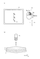
モニタ8は、表示手段であり、例えば、LCD(Liquid Crystal Display)などの表示装置により構成されており、例えば、カメラ12が撮像した試料Sの表面画像や、試料Sの表面に形成されるくぼみの画像などを表示する。
このモニタ8には、上記の画像と共に、マウス72(後述)の操作により当該モニタ8上を移動するカーソルKが表示可能となっている。
また、これ以外にもモニタ8は、操作部7において入力された硬さ試験の設定条件、硬さ試験の結果等を表示する。
The
The
In addition to this, the
操作部7は、キーボード71、マウス72等により構成される。
このうちマウス72は、図5(a)等に示すように、左釦(第1の押し釦)72a、右釦(第2の押し釦)72b、及び中央釦(第3の押し釦)72cを有し、ユーザによるドラッグ操作等を受け付けるポインティングデバイスである。
具体的に、マウス72は、ユーザによってなされる下記の第1指示〜第4指示等を受け付けて、これら第1指示〜第4指示に応じた操作信号を制御部6に対して出力する。
The
Among these, the
Specifically, the
「第1指示」とは、カーソルKの移動により、モニタ8に表示された試料Sの表面画像をモニタ8上で移動させる指示であり、例えば、左釦72aを押下した状態で、マウス72を任意の方向にドラッグ操作することで実行される(図5(a)参照)。
また、「第2指示」とは、カーソルKの移動により、試料台2の高さを変更させる指示であり、例えば、右釦72bを押下した状態で、マウス72を予め設定された所定の第1の方向(ここでは、Y方向)にドラッグ操作することで実行される(図6(a)参照)。
また、「第3指示」とは、カーソルKの移動により、モニタ8に表示された画面の明暗を変化させる指示であり、例えば、右釦72bを押下した状態で、マウス72を予め設定された所定の第2の方向(ここでは、X方向)にドラッグ操作することで実行される(図7(a)参照)。
また、「第4指示」とは、対物レンズ15の倍率を切り替える指示であり、例えば、中央釦72cを押下することで実行される(図8(a)参照)。
The “first instruction” is an instruction to move the surface image of the sample S displayed on the
The “second instruction” is an instruction to change the height of the
The “third instruction” is an instruction to change the brightness of the screen displayed on the
The “fourth instruction” is an instruction to switch the magnification of the
なお、第1指示〜第4指示を実行するためのマウス72の具体的な操作は、上記に限定されるものではなく、任意に設定することが可能である。
また、図5(a)、図6(a)、図7(a)の矢印は、ドラッグ操作を説明するために仮想的に記載したものであって、実際のモニタ8には表示されない。
The specific operation of the
Further, the arrows in FIGS. 5A, 6A, and 7A are virtually described for explaining the drag operation, and are not displayed on the
また、操作部7は、上記操作以外にも、当該硬さ試験機100による硬さ試験を実施する際の各種の条件の設定等を、ユーザが行う際に利用される。即ち、ユーザにより操作部7に所定の操作がなされると、その操作に応じた所定の操作信号が制御部6に出力される。
なお、各種の条件の設定とは、例えば、試験条件(試料Sの材質、圧子14aにより試料Sに負荷される試験力(N)、対物レンズ15の倍率、等の値)や、試験開始点、行・列数、ピッチ等の設定である。
In addition to the above operations, the
The various conditions are set, for example, as test conditions (value of the material of the sample S, test force (N) applied to the sample S by the
制御部6は、図4に示すように、CPU(Central Processing Unit)61、RAM(Random Access Memory)62、記憶部63等を備えて構成され、記憶部63に記憶された所定のプログラムが実行されることにより、所定の硬さ試験を行うための動作制御等を行う機能を有する。
As shown in FIG. 4, the
CPU61は、記憶部63に格納された処理プログラム等を読み出して、RAM62に展開して実行することにより、硬さ試験機100全体の制御を行う。
The
RAM62は、CPU61により実行された処理プログラム等を、RAM62内のプログラム格納領域に展開するとともに、入力データや上記処理プログラムが実行される際に生じる処理結果等をデータ格納領域に格納する。
The
記憶部63は、例えば、プログラムやデータ等を記憶するための、半導体メモリ等で構成された記録媒体(図示省略)を有しており、CPU61が硬さ試験機100全体を制御する機能を実現させるための各種データ、各種処理プログラム、これらプログラムの実行により処理されたデータ等を記憶する。
The
具体的には、記憶部63は、例えば、XYステージ制御プログラム631、オートフォーカスプログラム632、位置調整プログラム633、光量調整プログラム634、ターレット回転プログラム635、及び硬さ測定部制御プログラム636等を格納している。
Specifically, the
XYステージ制御プログラム631は、例えば、試料台2に試料Sを載置した後、試料Sとカメラ12とが対向するように、XYステージ3の位置を制御する機能をCPU61に実現させるプログラムである。
具体的には、CPU61は、XYステージ制御プログラム631を実行することにより、駆動機構部3Aを駆動させ、試料Sの表面の所定領域がカメラ12の真下に位置するようにXYステージ3を移動させる。
The XY
Specifically, the
オートフォーカスプログラム632は、例えば、試料Sの表面に対するオートフォーカスを行う機能をCPU61に実現させるプログラムである。
具体的には、CPU61は、オートフォーカスプログラム632を実行することにより、硬さ測定部1のカメラ12によって得られる画像情報に基づいて、AF(Z)ステージ4を昇降させ、試料Sの表面に対するオートフォーカスを行う。
The
Specifically, the
位置調整プログラム633は、例えば、上記XYステージ制御プログラム631やオートフォーカスプログラム632が実行された後、ユーザによりマウス72に第1指示がなされた場合、カーソルKの移動に合わせて試料台2を水平方向(X方向、Y方向)に移動させると共に、ユーザによりマウス72に第2指示がなされた場合、カーソルKの移動に合わせて試料台2を高さ方向(Z方向)に移動させる機能をCPU61に実現させるプログラムである。
For example, when the user gives a first instruction to the
具体的には、ユーザによりマウス72に第1指示や第2指示がなされた場合、マウス72からは、カーソルKの移動方向及び移動量に関する情報を含む操作信号がCPU61に出力される。
ここで、第1指示がなされた場合、CPU61は、位置調整プログラム633を実行することにより、駆動機構部3Aを駆動して、カーソルKの移動方向に応じた方向に、カーソルKの移動量に応じた分だけXYステージ3を移動させることで、試料台2をカーソルKの移動に合わせて水平方向に移動させる。
また、第2指示がなされた場合、CPU61は、位置調整プログラム633を実行することにより、AF(Z)ステージ4を駆動して、カーソルKの移動方向に応じた方向に、カーソルKの移動量に応じた分だけAF(Z)ステージ4を移動させることで、試料台2をカーソルKの移動に合わせて高さ方向に移動させる。
このため、モニタ8上の画像が、カーソルKの移動に合せて移動することとなる。
Specifically, when the first instruction or the second instruction is given to the
Here, when the first instruction is given, the
When the second instruction is given, the
For this reason, the image on the
また、このとき、CPU61は、試料台2と対向している対物レンズ15の倍率を参照し、当該対物レンズ15の倍率が高いほど、カーソルKの移動量に対する試料台2の水平方向及び高さ方向の移動量が小さくなるように制御している。
具体的に、画面の半分程度の移動のとき、倍率が(50x)の高倍対物レンズ15aでは、カーソルKの移動量に対する試料台2の水平方向及び高さ方向の移動量が(50μm)であり、倍率が(10x)の低倍対物レンズ15bでは、カーソルKの移動量に対する試料台2の水平方向及び高さ方向の移動量が(250μm)となる。
このため、対物レンズ15の倍率が切り替えられて画像の範囲が変わった場合にも、その画像に適したピッチで試料台2を移動させることができるようになっている。
At this time, the
Specifically, when moving about half of the screen, in the high magnification
Therefore, even when the magnification of the
CPU61は、かかる位置調整プログラム633を実行することにより、駆動機構部3A及びAF(Z)ステージ4と共に、位置調整手段として機能している。
The
光量調整プログラム634は、例えば、ユーザによりマウス72に第3指示がなされた場合、カーソルKの移動に合わせて照明装置11からの光の光量を変化させる機能をCPU61に実現させるプログラムである。
具体的には、ユーザによりマウス72に第3指示がなされた場合、マウス72からは、カーソルKの移動方向及び移動量に関する情報を含む操作信号がCPU61に出力される。
すると、CPU61は、光量調整プログラム634を実行することにより、マウス72からの操作信号に基づいて、カーソルKの移動量に応じた分だけ照明装置11からの光の光量を大きく或いは小さく変更する。
CPU61は、かかる光量調整プログラム634を実行することにより、光量調整手段として機能している。
The light
Specifically, when a third instruction is given to the
Then, the
The
ターレット回転プログラム635は、例えば、ユーザによりマウス72に第4指示がなされた場合、ターレット16を回転させる機能をCPU61に実現させるプログラムである。
具体的にが、ユーザによりマウス72に第4指示がなされた場合、マウス72から、中央釦72cの押下時間等に関する情報を含む操作信号がCPU61に出力される。
すると、CPU61は、ターレット回転プログラム635を実行することにより、押下時間が所定の長さを越えたと判断した場合に、ターレット駆動機構部16Aを制御して、ターレット16の回転を開始させ、押下が止められるまで継続して回転を続けさせる。
なお、中央釦72cが押下された状態でマウス72が右方向にドラッグ操作された場合にはターレット16を右回転させ、中央釦72cが押下された状態でマウス72が左方向にドラッグ操作された場合、ターレット16を左回転させる等の制御を行う構成とすることもできる。
CPU61は、かかるターレット回転プログラム635を実行することにより、ターレット駆動機構部16Aと共にターレット回転手段として機能している。
The
Specifically, when the user gives a fourth instruction to the
Then, when the
When the
The
硬さ測定部制御プログラム636は、例えば、硬さ測定部1に所定の動作を実行させる機能をCPU61に実現させるプログラムである。
具体的に、CPU61は、硬さ測定部制御プログラム636を実行することにより、圧子14aを所定の試験力で試料Sの表面に押し付けてくぼみを形成したり、カメラ12によって生成される試料Sの表面の画像情報に基づいてくぼみの対角線長さを計測したりするとともに、計測したくぼみの対角線長さに基づいて試料Sの硬さを算出する。
The hardness measurement
Specifically, the
なお、本実施形態の硬さ試験機100は、上記したXYステージ制御プログラム631、オートフォーカスプログラム632を備えない構成であっても良い。
Note that the
次に、本実施形態の硬さ試験機100の作用について説明する。
上記構成の硬さ試験機100においては、マウス72の操作により、XYステージ3、AF(Z)ステージ4、照明装置11、ターレット16等の各部を調整することが可能である。
Next, the operation of the
In the
例えば、図5(a)(b)に示すように、第1指示として、左釦72aが押下された状態で、マウス72が任意の方向にドラッグ操作された場合、モニタ8上の画像がカーソルKの移動に合せて移動するように、XYステージ3が水平方向に移動する。
For example, as shown in FIGS. 5A and 5B, when the
また、図6(a)(b)に示すように、第2指示として、右釦72bが押下された状態で、マウス72が所定の一方向(ここでは、Y方向)にドラッグ操作された場合、モニタ8上のカーソルKの移動に合わせて、AF(Z)ステージ4が高さ方向に移動する。
In addition, as shown in FIGS. 6A and 6B, as a second instruction, when the
また、図7(a)(b)に示すように、第3指示として、右釦72bが押下された状態で、マウス72が所定の一方向(ここでは、X方向)にドラッグ操作された場合、モニタ8上のカーソルKの移動に合わせて、モニタ8に表示されている画像の明暗が任意の明るさに変更される。
Further, as shown in FIGS. 7A and 7B, as a third instruction, when the
また、図8(a)(b)に示すように、第4指示として、中央釦72cが押下された場合、ターレット16が回転されて、対物レンズ15が切り替えられる。
As shown in FIGS. 8A and 8B, when the
以上のように、本実施形態の硬さ試験機100によれば、対物レンズ15を介して試料Sの表面を撮像するカメラ12と、カメラ12により撮像された試料Sの表面画像とカーソルKとを表示可能なモニタ8と、カーソルKの移動によりモニタ8に表示された試料Sの表面画像の水平方向の移動を指示する第1指示と、カーソルKの移動により試料台2の高さの変更を指示する第2指示と、を受け付けるマウス72と、ユーザにより第1指示がなされた場合、カーソルKの移動に合わせて試料台2を水平方向に移動させると共に、ユーザにより第2指示がなされた場合、カーソルKの移動に合わせて試料台2を高さ方向に移動させる位置調整手段(CPU61、位置調整プログラム633)と、を備えている。
ここで、マウス72は、左釦72a及び右釦72bを有し、ユーザによるドラッグ操作受け付け可能であって、第1指示は、ユーザにより左釦72aが押下された状態で、マウス72をドラッグ操作された場合に実行され、第2指示は、ユーザにより右釦72bが押下された状態で、マウス72が所定の第1の方向(Y方向)にドラッグ操作された場合に実行される。
このため、マウス72操作のみで試料台2を水平方向及び高さ方向に移動させることができる。
また、目線をモニタ8に表示された画像に向けたままで、水平方向及び高さ方向の試料Sの微量な位置調整を容易に行うことができる。
また、モニタ8上に、試料Sの表面画像が表示される画面と別に位置調整等を行うための操作バーを設ける必要がないため、モニタ8の画面構成を簡素化することができる。
よって、測定を行う際の操作性を良好にすることができる。
As described above, according to the
Here, the
For this reason, the
In addition, a minute position adjustment of the sample S in the horizontal direction and the height direction can be easily performed while keeping the line of sight toward the image displayed on the
Further, since it is not necessary to provide an operation bar for performing position adjustment or the like on the
Therefore, the operability when performing the measurement can be improved.
また、本実施形態の硬さ試験機100によれば、マウス72は、カーソルKの移動によりモニタ8に表示された画面の明暗を変化させる第3指示を受け付け可能であって、試料Sの表面に光を照射する照明装置11と、ユーザにより第3指示がなされた場合、カーソルKの移動に合わせて照明装置11からの光の光量を変化させる光量調整手段(CPU61、光量調整プログラム634)と、を備えている。
ここで、第3指示は、ユーザにより右釦72bが押下された状態で、マウス72が所定の第2の方向(X方向)にドラッグ操作された場合に実行される。
このため、マウス72操作のみで照明装置11から試料Sの表面に対して照射される光の光量を変更することができ、目線をモニタ8に表示された画像に向けたままで、画面の明暗を調整することができる。
よって、測定を行う際の操作性をより良好にすることができる。
Further, according to the
Here, the third instruction is executed when the
For this reason, it is possible to change the amount of light emitted from the illuminating
Therefore, the operability when performing the measurement can be improved.
また、本実施形態の硬さ試験機100によれば、マウス72は、対物レンズ15の倍率を切り替える第4指示を受け付け可能であり、圧子14a及び複数の対物レンズ15の搭載されたターレット16と、ユーザにより第4指示がなされた場合、ターレット16を回転させるターレット回転手段(CPU61、ターレット回転プログラム635)と、を備えている。
ここで、マウス72は、中央釦72cを有し、第4指示は、ユーザにより中央釦72cが押下された場合に実行される。
このため、マウス72の操作により、対物レンズ15を切り替えることができ、測定を行う際の操作性をより良好にすることができる。
Further, according to the
Here, the
For this reason, the
また、本実施形態の硬さ試験機100によれば、位置調整手段は、対物レンズ15の倍率が高くなるにつれて、カーソルKの移動量に対する試料台2の水平方向及び高さ方向の移動量を小さくするよう制御している。
このため、複数の異なる倍率の対物レンズ15が搭載された硬さ試験機100において、対物レンズ15を切り替えたとしても、その倍率にあったピッチで試料台2を移動させることになるため、測定を行う際の操作性をより良好にすることができる。
Further, according to the
For this reason, in the
なお、上記実施形態においては、マウス操作により第1指示や第2指示が行われた場合、XYステージ3やAF(Z)ステージ4(試料台2)が移動する構成を例示して説明したが、試料台2の代わりにカメラ12(対物レンズ15の位置)が水平方向或いは高さ方向に移動する構成とすることもできる。
In the above-described embodiment, the configuration in which the
また、モニタ8に表示されるカーソルKの近傍に、マウス72の指示操作と、これに対応した硬さ試験機100の各部の動作を案内した案内表示を表示させることとしても良い。
Further, in the vicinity of the cursor K displayed on the
100 硬さ試験機
10 試験機本体
1 硬さ測定部
2 試料台
3 XYステージ
3A XYステージ駆動機構部(位置調整手段)
4 AF(Z)ステージ(位置調整手段)
5 昇降機構部
6 制御部
61 CPU(位置調整手段、光量調整手段、ターレット回転手段)
62 RAM
63 記憶部
631 XYステージ制御プログラム
632 オートフォーカスプログラム
633 位置調整プログラム(位置調整手段)
634 光量調整プログラム(光量調整手段)
635 ターレット回転プログラム(ターレット回転手段)
636 測定部制御プログラム
7 操作部
71 キーボード
72 マウス(ポインティングデバイス)
72a 左釦(第1の押し釦)
72b 右釦(第2の押し釦)
72c 中央釦(第3の押し釦)
8 モニタ(表示手段)
11 照明装置(照明手段)
12 カメラ(撮像手段)
14 圧子軸
14a 圧子
15 対物レンズ
15a 高倍対物レンズ
15b 低倍対物レンズ
16 ターレット
16A ターレット駆動機構部(ターレット回転手段)
S 試料
K カーソル
DESCRIPTION OF
4 AF (Z) stage (position adjustment means)
5 Elevating
62 RAM
63
634 Light quantity adjustment program (light quantity adjustment means)
635 Turret rotation program (turret rotation means)
636 Measuring
72a Left button (first push button)
72b Right button (second push button)
72c Center button (third push button)
8 Monitor (display means)
11 Illumination device (illumination means)
12 Camera (imaging means)
14
S Sample K cursor
Claims (4)
対物レンズを介して試料の表面を撮像する撮像手段と、
前記撮像手段により撮像された試料の表面画像とカーソルとを表示可能な表示手段と、
試料の表面に光を照射する照明手段と、
前記カーソルの移動により前記表示手段に表示された試料の表面画像の移動を指示する第1指示と、前記カーソルの移動により前記試料台の高さの変更を指示する第2指示と、前記カーソルの移動により前記表示手段に表示された画面の明暗の変化を指示する第3指示と、を受け付けるポインティングデバイスと、
ユーザにより前記第1指示がなされた場合、前記カーソルの移動に合わせて前記試料台を水平方向に移動させると共に、ユーザにより前記第2指示がなされた場合、前記カーソルの移動に合わせて前記試料台を高さ方向に移動させる位置調整手段と、
ユーザにより前記第3指示がなされた場合、前記カーソルの移動に合わせて前記照明手段からの光の光量を変化させる光量調整手段と、
を備え、
前記ポインティングデバイスは、第1の押し釦及び第2の押し釦を有し、ユーザによるドラッグ操作を受け付け可能であって、
前記第1指示は、ユーザにより前記第1の押し釦が押下された状態で、前記ポインティングデバイスがドラッグ操作された場合に実行され、
前記第2指示は、ユーザにより前記第2の押し釦が押下された状態で、前記ポインティングデバイスが所定の第1の方向にドラッグ操作された場合に実行され、
前記第3指示は、ユーザにより前記第2の押し釦が押下された状態で、前記ポインティングデバイスが前記第1の方向と異なる所定の第2の方向にドラッグ操作された場合に実行されることを特徴とする硬さ試験機。 In a hardness tester for measuring the hardness of a sample by applying a predetermined test force with an indenter on the surface of the sample placed on the sample table to form a dent and measuring the size of the dent.
Imaging means for imaging the surface of the sample through the objective lens;
Display means capable of displaying a surface image of the sample imaged by the imaging means and a cursor;
Illumination means for irradiating the surface of the sample with light;
A first instruction for instructing movement of the surface image of the sample displayed on the display means by movement of the cursor; a second instruction for instructing change of the height of the sample stage by movement of the cursor; A pointing device for receiving a third instruction for instructing a change in brightness of the screen displayed on the display means by movement ;
When the user gives the first instruction, the sample stage is moved in the horizontal direction in accordance with the movement of the cursor, and when the user gives the second instruction, the sample stage is moved in accordance with the movement of the cursor. Position adjusting means for moving the
A light amount adjusting means for changing a light amount of the light from the illumination means in accordance with the movement of the cursor when the user gives the third instruction;
Equipped with a,
The pointing device has a first push button and a second push button, can accept a drag operation by a user,
The first instruction is executed when the pointing device is dragged in a state where the first push button is pressed by a user,
The second instruction is executed when the pointing device is dragged in a predetermined first direction while the second push button is pressed by a user,
The third instruction is executed when the pointing device is dragged in a predetermined second direction different from the first direction while the second push button is pressed by the user. Characteristic hardness testing machine.
前記圧子及び複数の前記対物レンズの搭載されたターレットと、
ユーザにより前記第4指示がなされた場合、前記ターレットを回転させるターレット回転手段と、
を備えることを特徴とする請求項1に記載の硬さ試験機。 The pointing device is capable of receiving a fourth instruction to switch the magnification of the objective lens;
A turret on which the indenter and the plurality of objective lenses are mounted;
Turret rotation means for rotating the turret when the user gives the fourth instruction;
The hardness tester according to claim 1, comprising:
前記第4指示は、ユーザにより前記第3の押し釦が押下された場合に実行されることを特徴とする請求項2に記載の硬さ試験機。 The pointing device has a third push button,
The hardness tester according to claim 2 , wherein the fourth instruction is executed when the user pushes the third push button.
Priority Applications (4)
| Application Number | Priority Date | Filing Date | Title |
|---|---|---|---|
| JP2011188472A JP5841379B2 (en) | 2011-08-31 | 2011-08-31 | Hardness testing machine |
| US13/453,197 US9207156B2 (en) | 2011-08-31 | 2012-04-23 | Hardness tester |
| EP12166991.5A EP2565619B1 (en) | 2011-08-31 | 2012-05-07 | Hardness tester |
| CN201210150255.7A CN102967518B (en) | 2011-08-31 | 2012-05-15 | Hardness tester |
Applications Claiming Priority (1)
| Application Number | Priority Date | Filing Date | Title |
|---|---|---|---|
| JP2011188472A JP5841379B2 (en) | 2011-08-31 | 2011-08-31 | Hardness testing machine |
Publications (2)
| Publication Number | Publication Date |
|---|---|
| JP2013050382A JP2013050382A (en) | 2013-03-14 |
| JP5841379B2 true JP5841379B2 (en) | 2016-01-13 |
Family
ID=46125188
Family Applications (1)
| Application Number | Title | Priority Date | Filing Date |
|---|---|---|---|
| JP2011188472A Active JP5841379B2 (en) | 2011-08-31 | 2011-08-31 | Hardness testing machine |
Country Status (4)
| Country | Link |
|---|---|
| US (1) | US9207156B2 (en) |
| EP (1) | EP2565619B1 (en) |
| JP (1) | JP5841379B2 (en) |
| CN (1) | CN102967518B (en) |
Families Citing this family (15)
| Publication number | Priority date | Publication date | Assignee | Title |
|---|---|---|---|---|
| JP5977556B2 (en) * | 2012-03-27 | 2016-08-24 | 株式会社ミツトヨ | Hardness testing machine |
| JP5977557B2 (en) | 2012-03-27 | 2016-08-24 | 株式会社ミツトヨ | Hardness testing machine |
| JP6017187B2 (en) | 2012-05-31 | 2016-10-26 | 株式会社ミツトヨ | Indentation testing machine |
| JP5955716B2 (en) | 2012-09-19 | 2016-07-20 | 株式会社ミツトヨ | Hardness tester and hardness test method |
| CN104769411B (en) * | 2012-11-05 | 2017-05-31 | 杰富意钢铁株式会社 | The rigid assay method of dynamic tensile and measure device of the outside plate of Vehicle component |
| CN103335905B (en) * | 2013-07-19 | 2015-03-11 | 江苏大学 | Method for measuring microhardness of curved surface |
| JP6305280B2 (en) * | 2014-08-28 | 2018-04-04 | 株式会社日立ハイテクサイエンス | X-ray fluorescence analyzer and sample display method thereof |
| JP6721306B2 (en) * | 2015-09-10 | 2020-07-15 | 株式会社ミツトヨ | Hardness tester |
| CN106153483A (en) * | 2016-08-27 | 2016-11-23 | 李子振 | A kind of durometer being applicable to rubber and operational approach thereof |
| CN111226106A (en) * | 2017-10-16 | 2020-06-02 | 茵品特有限责任公司 | Apparatus and method for automated workpiece testing |
| JP2019207116A (en) * | 2018-05-28 | 2019-12-05 | 株式会社島津製作所 | Hardness tester |
| CN108760518A (en) * | 2018-06-07 | 2018-11-06 | 江苏赛博宇华科技有限公司 | A kind of Mobile phone screen detection device |
| JP7144267B2 (en) | 2018-10-03 | 2022-09-29 | 株式会社ミツトヨ | hardness tester |
| JP7141296B2 (en) | 2018-10-03 | 2022-09-22 | 株式会社ミツトヨ | hardness tester |
| CN109323942A (en) * | 2018-10-15 | 2019-02-12 | 浙江染化宝检测服务有限公司 | A kind of leather hardness tester |
Family Cites Families (28)
| Publication number | Priority date | Publication date | Assignee | Title |
|---|---|---|---|---|
| US4613573A (en) * | 1982-05-20 | 1986-09-23 | Hitachi, Ltd. | Automatic bacterial colony transfer apparatus |
| US4667509A (en) | 1984-03-01 | 1987-05-26 | Page-Wilson Corporation | Digital tester for measuring the hardness of the material |
| JP2731864B2 (en) * | 1989-09-05 | 1998-03-25 | 新日本製鐵株式会社 | Indentation type hardness tester |
| US5375199A (en) * | 1991-06-04 | 1994-12-20 | Digital Equipment Corporation | System monitoring method and device including a graphical user interface to view and manipulate system information |
| JPH058455U (en) * | 1991-07-19 | 1993-02-05 | 日野自動車工業株式会社 | Micro Vickers hardness tester |
| US5479252A (en) * | 1993-06-17 | 1995-12-26 | Ultrapointe Corporation | Laser imaging system for inspection and analysis of sub-micron particles |
| JPH08262327A (en) | 1995-03-22 | 1996-10-11 | Moritetsukusu:Kk | Movement controller of x-y table |
| US6134954A (en) * | 1996-04-15 | 2000-10-24 | Massachusetts Institute Of Technology | Depth sensing indentation and methodology for mechanical property measurements |
| JP2000180330A (en) * | 1998-12-14 | 2000-06-30 | Edison Haado Kk | Durometer |
| JP2002098897A (en) * | 2000-09-21 | 2002-04-05 | Shimadzu Corp | Microscope |
| US6996264B2 (en) * | 2002-10-18 | 2006-02-07 | Leco Corporation | Indentation hardness test system |
| CN1226607C (en) | 2002-12-20 | 2005-11-09 | 北京有色金属研究总院 | Computer observing and controlling systems for microhardometer |
| US7121136B2 (en) * | 2002-12-25 | 2006-10-17 | Mitutoyo Corporation | Hardness testing apparatus |
| JP2004286542A (en) | 2003-03-20 | 2004-10-14 | Akashi Corp | Hardness testing machine |
| CA2526368A1 (en) * | 2003-05-20 | 2004-12-02 | Fluidigm Corporation | Method and system for microfluidic device and imaging thereof |
| US7315414B2 (en) * | 2004-03-31 | 2008-01-01 | Swift Instruments, Inc. | Microscope with adjustable stage |
| JP4261418B2 (en) | 2004-05-12 | 2009-04-30 | 株式会社ミツトヨ | Hardness tester and automatic hardness test method |
| JP2005337974A (en) * | 2004-05-28 | 2005-12-08 | Mitsutoyo Corp | Hardness testing machine |
| JP2006071415A (en) | 2004-09-01 | 2006-03-16 | Mitsutoyo Corp | Hardness tester |
| JP2007034050A (en) * | 2005-07-28 | 2007-02-08 | Olympus Corp | Observation apparatus and control method thereof |
| JP4923541B2 (en) * | 2005-11-30 | 2012-04-25 | 株式会社ニコン | microscope |
| JP4902371B2 (en) * | 2007-01-26 | 2012-03-21 | 株式会社ミツトヨ | Hardness testing machine |
| JP4958754B2 (en) * | 2007-12-07 | 2012-06-20 | 株式会社ミツトヨ | Hardness tester and calibration method for hardness tester |
| JP5017081B2 (en) | 2007-12-26 | 2012-09-05 | 株式会社ミツトヨ | Indentation tester and indentation test method |
| JP5192965B2 (en) * | 2008-09-26 | 2013-05-08 | オリンパス株式会社 | Microscope system, control program, and control method |
| JP5258678B2 (en) * | 2009-06-16 | 2013-08-07 | 株式会社ミツトヨ | Hardness testing machine |
| JP5501189B2 (en) | 2010-10-06 | 2014-05-21 | 株式会社ミツトヨ | Hardness testing machine |
| JP2012078306A (en) | 2010-10-06 | 2012-04-19 | Mitsutoyo Corp | Hardness test apparatus |
-
2011
- 2011-08-31 JP JP2011188472A patent/JP5841379B2/en active Active
-
2012
- 2012-04-23 US US13/453,197 patent/US9207156B2/en active Active
- 2012-05-07 EP EP12166991.5A patent/EP2565619B1/en active Active
- 2012-05-15 CN CN201210150255.7A patent/CN102967518B/en active Active
Also Published As
| Publication number | Publication date |
|---|---|
| EP2565619A3 (en) | 2018-03-21 |
| EP2565619A2 (en) | 2013-03-06 |
| CN102967518A (en) | 2013-03-13 |
| JP2013050382A (en) | 2013-03-14 |
| EP2565619B1 (en) | 2019-02-20 |
| US20130047712A1 (en) | 2013-02-28 |
| US9207156B2 (en) | 2015-12-08 |
| CN102967518B (en) | 2015-11-18 |
Similar Documents
| Publication | Publication Date | Title |
|---|---|---|
| JP5841379B2 (en) | Hardness testing machine | |
| JP5977556B2 (en) | Hardness testing machine | |
| JP5977557B2 (en) | Hardness testing machine | |
| US8566735B2 (en) | Hardness tester with a user interface for setting test locations | |
| JP2012078307A (en) | Hardness test apparatus | |
| US9582088B2 (en) | Microscope | |
| JP2013050379A (en) | Hardness-testing machine | |
| JP2013088530A (en) | Magnifying observation device | |
| JP5910407B2 (en) | Hardness tester and hardness test method in hardness tester | |
| US20080282197A1 (en) | Microscopic-Measurement Apparatus | |
| JP2020086293A (en) | Magnifying observation device | |
| JP6530287B2 (en) | Hardness tester and hardness test method | |
| JP2013019818A (en) | Hardness test device | |
| JP6040816B2 (en) | Hardness testing machine | |
| JP6094457B2 (en) | Hardness testing machine | |
| JP2006098794A (en) | Compound microscope and measuring method of compound microscope | |
| JP5962286B2 (en) | Hardness testing machine | |
| JP2011247842A (en) | Hardness tester | |
| JP2009162963A (en) | Confocal microscope and scanning method | |
| WO2024014079A1 (en) | Cell observation device and imaging method used in cell observation device | |
| US20220269062A1 (en) | Magnified observation apparatus | |
| JP2016180737A (en) | Hardness tester | |
| JP2020086294A (en) | Magnification observation device | |
| JP2006023487A (en) | Microscopic device | |
| JP2014092640A (en) | Microscope and method of controlling the same |
Legal Events
| Date | Code | Title | Description |
|---|---|---|---|
| A621 | Written request for application examination |
Free format text: JAPANESE INTERMEDIATE CODE: A621 Effective date: 20140704 |
|
| A977 | Report on retrieval |
Free format text: JAPANESE INTERMEDIATE CODE: A971007 Effective date: 20150313 |
|
| A131 | Notification of reasons for refusal |
Free format text: JAPANESE INTERMEDIATE CODE: A131 Effective date: 20150324 |
|
| A521 | Written amendment |
Free format text: JAPANESE INTERMEDIATE CODE: A523 Effective date: 20150514 |
|
| TRDD | Decision of grant or rejection written | ||
| A01 | Written decision to grant a patent or to grant a registration (utility model) |
Free format text: JAPANESE INTERMEDIATE CODE: A01 Effective date: 20151104 |
|
| A61 | First payment of annual fees (during grant procedure) |
Free format text: JAPANESE INTERMEDIATE CODE: A61 Effective date: 20151113 |
|
| R150 | Certificate of patent or registration of utility model |
Ref document number: 5841379 Country of ref document: JP Free format text: JAPANESE INTERMEDIATE CODE: R150 |
|
| R250 | Receipt of annual fees |
Free format text: JAPANESE INTERMEDIATE CODE: R250 |
|
| R250 | Receipt of annual fees |
Free format text: JAPANESE INTERMEDIATE CODE: R250 |