JP5827762B1 - Work vehicle and operator protection guard - Google Patents

Work vehicle and operator protection guard Download PDF

Info

Publication number
JP5827762B1
JP5827762B1 JP2014561614A JP2014561614A JP5827762B1 JP 5827762 B1 JP5827762 B1 JP 5827762B1 JP 2014561614 A JP2014561614 A JP 2014561614A JP 2014561614 A JP2014561614 A JP 2014561614A JP 5827762 B1 JP5827762 B1 JP 5827762B1
Authority
JP
Japan
Prior art keywords
frame
vertical frame
cab
guard
bent
Prior art date
Legal status (The legal status is an assumption and is not a legal conclusion. Google has not performed a legal analysis and makes no representation as to the accuracy of the status listed.)
Expired - Fee Related
Application number
JP2014561614A
Other languages
Japanese (ja)
Other versions
JPWO2015087950A1 (en
Inventor
洋志 阿部
洋志 阿部
佐々木 誠
誠 佐々木
Current Assignee (The listed assignees may be inaccurate. Google has not performed a legal analysis and makes no representation or warranty as to the accuracy of the list.)
Komatsu Ltd
Original Assignee
Komatsu Ltd
Priority date (The priority date is an assumption and is not a legal conclusion. Google has not performed a legal analysis and makes no representation as to the accuracy of the date listed.)
Filing date
Publication date
Application filed by Komatsu Ltd filed Critical Komatsu Ltd
Application granted granted Critical
Publication of JP5827762B1 publication Critical patent/JP5827762B1/en
Publication of JPWO2015087950A1 publication Critical patent/JPWO2015087950A1/en
Expired - Fee Related legal-status Critical Current
Anticipated expiration legal-status Critical

Links

Images

Classifications

    • EFIXED CONSTRUCTIONS
    • E02HYDRAULIC ENGINEERING; FOUNDATIONS; SOIL SHIFTING
    • E02FDREDGING; SOIL-SHIFTING
    • E02F9/00Component parts of dredgers or soil-shifting machines, not restricted to one of the kinds covered by groups E02F3/00 - E02F7/00
    • E02F9/16Cabins, platforms, or the like, for drivers
    • E02F9/163Structures to protect drivers, e.g. cabins, doors for cabins; Falling object protection structure [FOPS]; Roll over protection structure [ROPS]

Abstract

運転員保護ガードの設けられたキャブ内からの視野を拡大できる作業車両を提供する。キャブの前方に設けられたフロントガード(100)は、フロントガード(100)の外縁を構成するフレーム(130)を有している。フレーム(130)は、上枠(140)と下枠(150)と右縦枠(160)と左縦枠(170)とが枠組みされて形成されている。右縦枠(160)は、縦枠屈曲部(161)を有し、縦枠屈曲部(161)から下枠(150)に近づくにつれて、キャブに向かって後方に延びている。Provided is a work vehicle capable of expanding a field of view from inside a cab provided with an operator protection guard. The front guard (100) provided in front of the cab has a frame (130) that constitutes an outer edge of the front guard (100). The frame (130) is formed by framing an upper frame (140), a lower frame (150), a right vertical frame (160), and a left vertical frame (170). The right vertical frame (160) has a vertical frame bent portion (161), and extends rearward toward the cab as the vertical frame bent portion (161) approaches the lower frame (150).

Description

本発明は、作業車両および運転員保護ガードに関する。   The present invention relates to a work vehicle and an operator protection guard.

油圧ショベル、スクラップローダなどの作業車両は、作業車両を操作する運転員が搭乗するキャブを備えている。キャブには、キャブの前方または上方からキャブに飛来する物体に対して運転員を適切に保護するための、運転員保護ガードが設けられている。   A work vehicle such as a hydraulic excavator or a scrap loader includes a cab on which an operator who operates the work vehicle is boarded. The cab is provided with an operator protection guard for appropriately protecting the operator against an object flying to the cab from the front or upper side of the cab.

従来の運転員保護ガードは、たとえば特許5355831号明細書(特許文献1)に開示されている。この文献に開示されたフロントガードでは、縦横に交差する板部材が、キャブ内に着座する運転員の視界を遮らないように、運転員の視点を中心として放射状に配置されている。   A conventional operator protection guard is disclosed in, for example, Japanese Patent No. 5355831 (Patent Document 1). In the front guard disclosed in this document, plate members that intersect vertically and horizontally are arranged radially about the operator's viewpoint so as not to obstruct the field of view of the operator seated in the cab.

特許5355831号明細書Japanese Patent No. 535531

特許5355831号明細書(特許文献1)に開示されたフロントガードでは、格子状に組み合わせた板状の部材のそれぞれを運転員の視線と平行に配置することにより、運転席からの視界を確保している。しかしながら、運転員保護ガードを備えているガード付きキャブには、キャブ内の運転席からの視界のさらなる向上が求められており、従来の運転員保護ガードの構造では必ずしも十分とはいえず依然として改良の余地がある。   In the front guard disclosed in Japanese Patent No. 5355831 (Patent Document 1), each of the plate-like members combined in a lattice shape is arranged in parallel with the line of sight of the driver, thereby ensuring visibility from the driver's seat. ing. However, the guarded cab equipped with the operator protection guard is required to further improve the visibility from the driver's seat in the cab, and the conventional operator protection guard structure is not necessarily sufficient and still improved. There is room for.

本発明の目的は、運転員保護ガードの設けられたキャブ内からの視野を拡大できる作業車両および運転員保護ガードを提供することである。   An object of the present invention is to provide a work vehicle and an operator protection guard capable of expanding a field of view from inside a cab provided with an operator protection guard.

本発明の作業車両は、作業機と、作業機の側方に配置されたキャブと、キャブの前方に設けられた運転員保護ガードとを備えている。運転員保護ガードは、運転員保護ガードの外縁を構成する枠体を含んでいる。枠体は、上枠と、下枠と、右縦枠と、左縦枠とを有している。枠体は、上枠と下枠と右縦枠と左縦枠とが枠組みされて形成されている。右縦枠と左縦枠とのうち作業機に近い一方の縦枠は、縦枠屈曲部を有し、縦枠屈曲部から下枠に近づくにつれてキャブに向かって後方に延びている。   The work vehicle according to the present invention includes a work machine, a cab disposed on the side of the work machine, and an operator protection guard provided in front of the cab. The operator protection guard includes a frame that forms the outer edge of the operator protection guard. The frame has an upper frame, a lower frame, a right vertical frame, and a left vertical frame. The frame body is formed by an upper frame, a lower frame, a right vertical frame, and a left vertical frame. One of the right vertical frame and the left vertical frame, which is close to the work implement, has a vertical frame bent portion, and extends rearward toward the cab as the vertical frame bent portion approaches the lower frame.

上記の作業車両において、上枠は、板材で形成されている。
上記の作業車両において、上枠は、幅広部を両端に有し、幅広部より幅の狭い幅狭部を中央部分に有している。
In the work vehicle described above, the upper frame is formed of a plate material.
In the work vehicle described above, the upper frame has a wide portion at both ends, and a narrow portion narrower than the wide portion at the center portion.

上記の作業車両において、下枠と、右縦枠と、左縦枠とは、パイプで形成されている。
上記の作業車両において、右縦枠と左縦枠とのうち作業機に近い一方の縦枠に、運転員保護ガードをキャブに取り付ける複数の取付部が設けられている。一方の縦枠は、下枠に連結される下端部を有している。最も下側の取付部よりも下端部に近い位置に縦枠屈曲部が形成されている。
In the work vehicle described above, the lower frame, the right vertical frame, and the left vertical frame are formed of pipes.
In the work vehicle described above, a plurality of attachment portions for attaching the operator protection guard to the cab are provided in one of the right vertical frame and the left vertical frame that is close to the work implement. One vertical frame has a lower end connected to the lower frame. A vertical frame bent portion is formed at a position closer to the lower end than the lowermost mounting portion.

上記の作業車両において、取付部は、ヒンジ構造を有している。運転員保護ガードは、ヒンジ構造を回転中心として、キャブに対し相対回転する。   In the work vehicle described above, the attachment portion has a hinge structure. The operator protection guard rotates relative to the cab with the hinge structure as the center of rotation.

上記の作業車両において、下枠は、下枠屈曲部を有している。下枠は、下枠屈曲部から右縦枠と左縦枠とのうち作業機に近い一方の縦枠に近づくにつれて、キャブに向かって後方に延びている。   In the work vehicle described above, the lower frame has a lower frame bent portion. The lower frame extends rearward toward the cab as it approaches one of the right vertical frame and the left vertical frame that is closer to the work implement from the lower frame bent portion.

本発明の運転員保護ガードは、作業機械のキャブの前方に設けられる運転員保護ガードであって、運転員保護ガードの外縁を構成する枠体を備えている。枠体は、上枠と、下枠と、右縦枠と、左縦枠とを有している。上枠は、板材で形成されている。下枠、右縦枠および左縦枠は、パイプで形成されている。右縦枠および左縦枠の少なくともいずれか一方が、縦枠屈曲部を有している。   The operator protection guard according to the present invention is an operator protection guard provided in front of the cab of the work machine, and includes a frame that forms the outer edge of the operator protection guard. The frame has an upper frame, a lower frame, a right vertical frame, and a left vertical frame. The upper frame is formed of a plate material. The lower frame, the right vertical frame, and the left vertical frame are formed of pipes. At least one of the right vertical frame and the left vertical frame has a vertical frame bent portion.

本発明によれば、運転員保護ガードの設けられたキャブ内からの視野を拡大できる作業車両を実現することができる。   ADVANTAGE OF THE INVENTION According to this invention, the working vehicle which can expand the visual field from the cab provided with the operator protection guard is realizable.

本発明の第一実施形態における作業車両の構成の概略を示す斜視図である。It is a perspective view which shows the outline of a structure of the work vehicle in 1st embodiment of this invention. 本発明の第一実施形態におけるガード付きキャブの構成の概略を示す斜視図である。It is a perspective view which shows the outline of a structure of the cab with a guard in 1st embodiment of this invention. 本発明の第一実施形態におけるフロントガードの構成の概略を示す第1の斜視図である。It is a 1st perspective view which shows the outline of a structure of the front guard in 1st embodiment of this invention. 本発明の第一実施形態におけるフロントガードの構成の概略を示す第2の斜視図である。It is a 2nd perspective view which shows the outline of a structure of the front guard in 1st embodiment of this invention. ガード付きキャブの、フロントガードの上枠付近の構造を示す斜視図である。It is a perspective view which shows the structure of the upper frame of a front guard of the cab with a guard. フロントガードの上枠付近の構造を示す斜視図である。It is a perspective view showing the structure near the upper frame of the front guard. フロントガードの上枠の斜視図である。It is a perspective view of the upper frame of a front guard. ガード付きキャブの、フロントガードの下枠付近の構造を示す斜視図である。It is a perspective view which shows the structure of the lower frame of a front guard of the cab with a guard. ガード付きキャブの一部の下面図である。It is a bottom view of a part of a cab with a guard. フロントガードをキャブにロックするロック装置を示す斜視図である。It is a perspective view which shows the locking device which locks a front guard to a cab. 図10に示すロック装置の分解斜視図である。It is a disassembled perspective view of the locking device shown in FIG. キャブに対して開状態のフロントガードを示す平面図である。It is a top view which shows the front guard of an open state with respect to a cab. 第二実施形態のガード付きキャブの、フロントガードの下枠付近の構造を示す斜視図である。It is a perspective view which shows the structure of the lower frame vicinity of the front guard of the cab with a guard of 2nd embodiment. 第二実施形態のガード付きキャブの一部の下面図である。It is a bottom view of a part of the guarded cab of the second embodiment. ガード付きキャブにおけるキャブ内からの視野を示す模式図である。It is a schematic diagram which shows the visual field from the cab in a cab with a guard.

以下、本発明の実施の形態について図に基づいて説明する。
(第一実施形態)
まず本発明の一実施の形態における作業車両の構成について説明する。以下、本発明の思想を適用可能な作業車両の一例である油圧ショベルについて説明するが、本発明はキャブを備えた作業車両に適用可能である。
Hereinafter, embodiments of the present invention will be described with reference to the drawings.
(First embodiment)
First, the configuration of the work vehicle in one embodiment of the present invention will be described. Hereinafter, although the hydraulic excavator which is an example of the working vehicle which can apply the thought of this invention is demonstrated, this invention is applicable to the working vehicle provided with the cab.

図1は、本発明の第一実施形態における作業車両としての、油圧ショベル1の構成の概略を示す斜視図である。図1に示すように、油圧ショベル1は、走行体2と、旋回体3と、作業機4と、ガード付きキャブ15とを主に備えている。走行体2と旋回体3とにより、作業車両本体が主に構成されている。   FIG. 1 is a perspective view showing an outline of a configuration of a hydraulic excavator 1 as a work vehicle in the first embodiment of the present invention. As shown in FIG. 1, the excavator 1 mainly includes a traveling body 2, a revolving body 3, a work implement 4, and a guarded cab 15. The traveling vehicle body 2 and the revolving body 3 mainly constitute a work vehicle main body.

走行体2は、左右一対の履帯2aを有している。走行体2は、一対の履帯2aが回転することにより自走可能に構成されている。旋回体3は、走行体2に対して旋回自在に設置されている。   The traveling body 2 has a pair of left and right crawler belts 2a. The traveling body 2 is configured to be capable of self-running when the pair of crawler belts 2a rotate. The swivel body 3 is installed so as to be turnable with respect to the traveling body 2.

旋回体3は、前方左側に、運転員が油圧ショベル1を操作するための空間であるキャブ5を含んでいる。旋回体3は、後方側に、エンジンを収納するエンジンルーム6、およびカウンタウェイト7を含んでいる。なお、本実施の形態では、キャブ5内に運転員が着座した状態で、運転員の前方側(正面側)を旋回体3の前方側とし、これと反対側、つまり運転員の後方側を旋回体3の後方側とし、着座状態での運転員の左側を旋回体3の左側とし、着座状態での運転員の右側を旋回体3の右側とする。以降は、旋回体3の前後左右と作業車両の前後左右は一致しているとする。   The swivel body 3 includes a cab 5 that is a space for an operator to operate the hydraulic excavator 1 on the front left side. The revolving structure 3 includes an engine room 6 that houses the engine and a counterweight 7 on the rear side. In this embodiment, with the operator seated in the cab 5, the front side (front side) of the operator is the front side of the revolving structure 3, and the opposite side, that is, the rear side of the operator is The left side of the operator in the seated state is the left side of the swing body 3, and the right side of the operator in the seated state is the right side of the swing body 3. Hereinafter, it is assumed that the front / rear / left / right of the revolving structure 3 and the front / rear / left / right of the work vehicle coincide.

旋回体3は、旋回フレーム10を含んでいる。旋回フレーム10は、作業車両本体に含まれている。旋回フレーム10は、走行体2の上方に配置されており、走行体2に対して任意の方向に旋回自在に設けられている。作業機4、ガード付きキャブ15およびカウンタウェイト7は、旋回フレーム10に搭載されており、旋回フレーム10の上面に配置されている。   The swivel body 3 includes a swivel frame 10. The turning frame 10 is included in the work vehicle main body. The turning frame 10 is disposed above the traveling body 2 and is provided so as to be able to turn in any direction with respect to the traveling body 2. The work machine 4, the guarded cab 15 and the counterweight 7 are mounted on the revolving frame 10 and are disposed on the upper surface of the revolving frame 10.

土砂の掘削などの作業を行なう作業機4は、上下方向に作動可能に、旋回体3により軸支されている。作業機4は、旋回体3の前方側の略中央部に上下方向に作動可能に取り付けられたブーム4aと、ブーム4aの先端部に前後方向に作動可能に取り付けられたアーム4bと、アーム4bの先端部に前後方向に作動可能に取り付けられたバケット4cとを有している。ブーム4a、アーム4bおよびバケット4cはそれぞれ、油圧シリンダ4dによって、駆動されるように構成されている。   A work machine 4 for performing work such as excavation of earth and sand is pivotally supported by a revolving body 3 so as to be operable in the vertical direction. The work implement 4 includes a boom 4a that is operably attached to a substantially central portion on the front side of the revolving structure 3, an arm 4b that is operably attached to the front end of the boom 4a, and an arm 4b. And a bucket 4c that is operatively attached to the front end portion in the front-rear direction. The boom 4a, the arm 4b, and the bucket 4c are each configured to be driven by a hydraulic cylinder 4d.

ガード付きキャブ15は、旋回体3の前方左側に配置されている。作業機4は、ガード付きキャブ15に対し、ガード付きキャブ15の側方の一方である右側に配置されている。   The guarded cab 15 is disposed on the front left side of the revolving structure 3. The work machine 4 is disposed on the right side which is one side of the guarded cab 15 with respect to the guarded cab 15.

図2は、本発明の第一実施形態におけるガード付きキャブ15の構成の概略を示す斜視図である。図2に示すように、ガード付きキャブ15は、油圧ショベル1を操作する運転員が搭乗するキャブ5と、運転員を保護する運転員保護ガードとを含んでいる。運転員保護ガードは、フロントガード100を含んでいる。フロントガード100は、キャブ5に取り付けられている。フロントガード100は、キャブ5の前方からの飛来物に対する運転員保護を目的として、キャブ5の前方に設けられている。   FIG. 2 is a perspective view schematically showing the configuration of the guarded cab 15 in the first embodiment of the present invention. As shown in FIG. 2, the guarded cab 15 includes a cab 5 on which an operator who operates the excavator 1 is boarded, and an operator protection guard that protects the operator. The operator protection guard includes a front guard 100. The front guard 100 is attached to the cab 5. The front guard 100 is provided in front of the cab 5 for the purpose of protecting the operator against flying objects from the front of the cab 5.

フロントガード100は、複数の第1板部材110と、複数の第2板部材120とを備えている。それぞれの第1板部材110は、1枚の板から形成されている。それぞれの第2板部材120は、1枚の板から形成されている。フロントガード100は、複数の第1板部材110の各々の長手方向DR1と、複数の第2板部材120の各々の長手方向DR2とが交差するように、複数の第1板部材110と複数の第2板部材120とが格子状に組み立てられた構成を有している。   The front guard 100 includes a plurality of first plate members 110 and a plurality of second plate members 120. Each first plate member 110 is formed from a single plate. Each second plate member 120 is formed from a single plate. The front guard 100 includes a plurality of first plate members 110 and a plurality of first plate members 110 such that each longitudinal direction DR1 of the plurality of first plate members 110 and each longitudinal direction DR2 of the plurality of second plate members 120 intersect each other. The second plate member 120 is assembled in a lattice shape.

複数の第1板部材110および複数の第2板部材120によって形成されている格子を取り囲むように、枠体としてのフレーム130が設けられている。当該格子は、フレーム130によってその周囲を支持されている。フロントガード100は、格子状に組み立てられた複数の第1板部材110および複数の第2板部材120を取り囲むフレーム130を備えている。フレーム130は、フロントガード100の外縁を構成している。複数の第1板部材110と複数の第2板部材120とは、フレーム130を介在させて、キャブ5の前方側の表面に取り付けられている。   A frame 130 as a frame body is provided so as to surround a lattice formed by the plurality of first plate members 110 and the plurality of second plate members 120. The perimeter of the grid is supported by the frame 130. The front guard 100 includes a frame 130 that surrounds the plurality of first plate members 110 and the plurality of second plate members 120 assembled in a lattice shape. The frame 130 constitutes the outer edge of the front guard 100. The plurality of first plate members 110 and the plurality of second plate members 120 are attached to the front surface of the cab 5 with the frame 130 interposed therebetween.

図3は、本発明の第一実施形態におけるフロントガード100の構成の概略を示す第1の斜視図である。図4は、本発明の第一実施形態におけるフロントガード100の構成の概略を示す第2の斜視図である。   FIG. 3 is a first perspective view showing an outline of the configuration of the front guard 100 in the first embodiment of the present invention. FIG. 4 is a second perspective view schematically showing the configuration of the front guard 100 in the first embodiment of the present invention.

図3および図4に示すように、フロントガード100のフレーム130は、上枠140と、下枠150と、右縦枠160と、左縦枠170とを有している。フレーム130は、上枠140と下枠150と右縦枠160と左縦枠170とが、枠組みされて形成されている。   As shown in FIGS. 3 and 4, the frame 130 of the front guard 100 includes an upper frame 140, a lower frame 150, a right vertical frame 160, and a left vertical frame 170. The frame 130 is formed by a framework of an upper frame 140, a lower frame 150, a right vertical frame 160, and a left vertical frame 170.

下枠150、右縦枠160および左縦枠170は、パイプを予め定められた形状に曲げ変形して適宜連結することで形成されている。上枠140は、板材で形成されている。詳細を後述するように、上枠140は、相対的に幅の広い幅広部141,142を両端に有しており、相対的に幅の狭い幅狭部143を中央部分に有している。   The lower frame 150, the right vertical frame 160, and the left vertical frame 170 are formed by bending and deforming a pipe into a predetermined shape and appropriately connecting them. The upper frame 140 is made of a plate material. As will be described in detail later, the upper frame 140 has relatively wide portions 141 and 142 at both ends, and has a relatively narrow portion 143 at the center.

下枠150は、右枠部分153と、中央枠部分154と、左枠部分155とを有している。下枠150は、下枠屈曲部151,152を有している。下枠屈曲部151は、右枠部分153と中央枠部分154との連結部分に設けられている。下枠屈曲部152は、左枠部分155と中央枠部分154との連結部分に設けられている。   The lower frame 150 includes a right frame portion 153, a central frame portion 154, and a left frame portion 155. The lower frame 150 has lower frame bent portions 151 and 152. The lower frame bent portion 151 is provided at a connection portion between the right frame portion 153 and the central frame portion 154. The lower frame bent portion 152 is provided at a connection portion between the left frame portion 155 and the central frame portion 154.

下枠150は、下枠屈曲部151および下枠屈曲部152において屈曲した形状を有している。右枠部分153の延びる方向と、中央枠部分154の延びる方向とは、互いに交差している。左枠部分155の延びる方向と、中央枠部分154の延びる方向とは、互いに交差している。   The lower frame 150 has a shape bent at the lower frame bent portion 151 and the lower frame bent portion 152. The extending direction of the right frame portion 153 and the extending direction of the central frame portion 154 intersect each other. The extending direction of the left frame portion 155 and the extending direction of the central frame portion 154 intersect each other.

本実施形態のフロントガード100は、5枚の第1板部材110を有している。下枠屈曲部151は、右から2番目の第1板部材110の右側に設けられている。下枠屈曲部152は、左から2番目の第1板部材110の左側に設けられている。   The front guard 100 of the present embodiment has five first plate members 110. The lower frame bent portion 151 is provided on the right side of the second first plate member 110 from the right. The lower frame bent portion 152 is provided on the left side of the second first plate member 110 from the left.

右縦枠160は、下枠部分163と、中央枠部分164と、上枠部分165とを有している。右縦枠160は、縦枠屈曲部161,162を有している。縦枠屈曲部161は、下枠部分163と中央枠部分164との連結部分に設けられている。縦枠屈曲部162は、上枠部分165と中央枠部分164との連結部分に設けられている。   The right vertical frame 160 has a lower frame portion 163, a central frame portion 164, and an upper frame portion 165. The right vertical frame 160 has vertical frame bent portions 161 and 162. The vertical frame bent portion 161 is provided at a connection portion between the lower frame portion 163 and the central frame portion 164. The vertical frame bent portion 162 is provided at a connection portion between the upper frame portion 165 and the central frame portion 164.

右縦枠160は、縦枠屈曲部161および縦枠屈曲部162において屈曲した形状を有している。下枠部分163の延びる方向と、中央枠部分164の延びる方向とは、互いに交差している。上枠部分165の延びる方向と、中央枠部分164の延びる方向とは、互いに交差している。   The right vertical frame 160 has a shape bent at the vertical frame bent portion 161 and the vertical frame bent portion 162. The direction in which the lower frame portion 163 extends and the direction in which the central frame portion 164 extends intersect each other. The direction in which the upper frame portion 165 extends and the direction in which the central frame portion 164 extends intersect each other.

本実施形態のフロントガード100は、4枚の第2板部材120を有している。縦枠屈曲部161は、最も下の第2板部材120に対して下側に設けられている。縦枠屈曲部162は、最も上の第2板部材120に対して上側に設けられている。   The front guard 100 according to the present embodiment includes four second plate members 120. The vertical frame bent portion 161 is provided on the lower side with respect to the lowermost second plate member 120. The vertical frame bending portion 162 is provided on the upper side with respect to the uppermost second plate member 120.

右縦枠160は、下端部166と、上端部167とを有している。右縦枠160は、下端部166において、下枠150に連結されている。右縦枠160は、上端部167において、上枠140に連結されている。   The right vertical frame 160 has a lower end 166 and an upper end 167. The right vertical frame 160 is connected to the lower frame 150 at the lower end 166. The right vertical frame 160 is connected to the upper frame 140 at the upper end 167.

右縦枠160の下枠部分163は、縦枠屈曲部161から下枠150に近づくにつれて、キャブ5に向かって後方に延びている。右縦枠160は、縦枠屈曲部161において、下枠150に連結される下端部166がキャブ5に近づく方向に屈曲している。ガード付きキャブ15が旋回フレーム10に搭載された状態で、右縦枠160の下端部166は、縦枠屈曲部161よりも、旋回体3の後方側に配置されている。   The lower frame portion 163 of the right vertical frame 160 extends rearward toward the cab 5 as it approaches the lower frame 150 from the vertical frame bent portion 161. The right vertical frame 160 is bent in the direction in which the lower end portion 166 connected to the lower frame 150 approaches the cab 5 at the vertical frame bent portion 161. In a state where the guarded cab 15 is mounted on the revolving frame 10, the lower end portion 166 of the right vertical frame 160 is disposed on the rear side of the revolving structure 3 with respect to the vertical frame bending portion 161.

右縦枠160の上枠部分165は、縦枠屈曲部162から上枠140に近づくにつれて、キャブ5に向かって後方に延びている。右縦枠160は、縦枠屈曲部162において、上枠140に連結される上端部167がキャブ5に近づく方向に屈曲している。ガード付きキャブ15が旋回フレーム10に搭載された状態で、右縦枠160の上端部167は、縦枠屈曲部162よりも、旋回体3の後方側に配置されている。   The upper frame portion 165 of the right vertical frame 160 extends rearward toward the cab 5 as it approaches the upper frame 140 from the vertical frame bent portion 162. The right vertical frame 160 is bent at a vertical frame bent portion 162 in a direction in which an upper end portion 167 connected to the upper frame 140 approaches the cab 5. In a state where the guarded cab 15 is mounted on the revolving frame 10, the upper end portion 167 of the right vertical frame 160 is disposed on the rear side of the revolving structure 3 with respect to the vertical frame bending portion 162.

右縦枠160の下枠部分163と、右縦枠160の上枠部分165とは、中央枠部分164に対して、同じ方向に屈曲している。図3に示す一点鎖線は中央枠部分164の延びる方向を示し、図3に示す矢印は中央枠部分164の延びる方向に対して下枠部分163が屈曲する方向を示している。   The lower frame portion 163 of the right vertical frame 160 and the upper frame portion 165 of the right vertical frame 160 are bent in the same direction with respect to the central frame portion 164. 3 indicates the direction in which the central frame portion 164 extends, and the arrow illustrated in FIG. 3 indicates the direction in which the lower frame portion 163 bends with respect to the direction in which the central frame portion 164 extends.

図4に示すように、右縦枠160の中央枠部分164には、ボルト装着部168が二箇所設けられている。二箇所のボルト装着部168は、右縦枠160の延びる方向に間隔を空けて配置されている。   As shown in FIG. 4, two bolt mounting portions 168 are provided in the center frame portion 164 of the right vertical frame 160. The two bolt mounting portions 168 are arranged at intervals in the direction in which the right vertical frame 160 extends.

二箇所のボルト装着部168のうち下端部166により近い一方に対して下端部166側に、縦枠屈曲部161が形成されている。縦枠屈曲部161は、最も下側のボルト装着部168よりも下端部166に近い位置に、形成されている。二箇所のボルト装着部168のうち上端部167により近い一方に対して上端部167側に、縦枠屈曲部162が形成されている。縦枠屈曲部162は、最も上側のボルト装着部168よりも上端部167に近い位置に、形成されている。   A vertical frame bent portion 161 is formed on the lower end 166 side with respect to one of the two bolt mounting portions 168 closer to the lower end 166. The vertical frame bent portion 161 is formed at a position closer to the lower end portion 166 than the lowest bolt mounting portion 168. A vertical frame bent portion 162 is formed on the upper end 167 side with respect to one of the two bolt mounting portions 168 closer to the upper end 167. The vertical frame bent portion 162 is formed at a position closer to the upper end portion 167 than the uppermost bolt mounting portion 168.

各々のボルト装着部168には、ヒンジ部320が固定される。ボルトがヒンジ部320を貫通してボルト装着部168に固定されることにより、ヒンジ部320はフロントガード100に固定される。   A hinge part 320 is fixed to each bolt mounting part 168. As the bolt passes through the hinge part 320 and is fixed to the bolt mounting part 168, the hinge part 320 is fixed to the front guard 100.

ヒンジ部320はまた、ブラケット310に固定される。ボルトがヒンジ部320を貫通してブラケット310に固定されることにより、ヒンジ部320はブラケット310に固定される。ブラケット310は、キャブ5の右フロントピラーの前面に取り付けられる。フロントガード100は、ブラケット310およびヒンジ部320を介在して、キャブ5に取り付けられている。   The hinge part 320 is also fixed to the bracket 310. As the bolt passes through the hinge part 320 and is fixed to the bracket 310, the hinge part 320 is fixed to the bracket 310. The bracket 310 is attached to the front surface of the right front pillar of the cab 5. The front guard 100 is attached to the cab 5 with a bracket 310 and a hinge part 320 interposed.

ブラケット310、ヒンジ部320およびボルト装着部168は、フロントガード100をキャブ5に開閉可能に取り付ける取付部を構成している。ボルト装着部168が右縦枠160の二箇所に設けられているので、複数の取付部が設けられていることになる。フロントガード100は、ヒンジ部320を回転中心として、キャブ5に対し相対回転可能に設けられている。   The bracket 310, the hinge portion 320, and the bolt mounting portion 168 constitute an attachment portion that attaches the front guard 100 to the cab 5 so as to be opened and closed. Since the bolt mounting portions 168 are provided at two locations of the right vertical frame 160, a plurality of attachment portions are provided. The front guard 100 is provided so as to be rotatable relative to the cab 5 with the hinge part 320 as a rotation center.

右縦枠160が屈曲した形状を有しているために、右縦枠160の中央枠部分164と、キャブ5の前面との間には、隙間が形成されている。この隙間に、フロントガード100をキャブ5に取り付けるための取付部が配置されている。右縦枠160は、右縦枠160の中央枠部分164とキャブ5との間に取付部の設置を可能にし、かつ右縦枠160の下端部166および上端部167がキャブ5の前面近くに配置されるように、二箇所の縦枠屈曲部161,162において屈曲した形状を有している。右縦枠160の両端部は、中央枠部分164よりも、キャブ5の前面により近い位置に配置されている。   Since the right vertical frame 160 has a bent shape, a gap is formed between the central frame portion 164 of the right vertical frame 160 and the front surface of the cab 5. An attachment portion for attaching the front guard 100 to the cab 5 is disposed in the gap. The right vertical frame 160 enables installation of a mounting portion between the central frame portion 164 of the right vertical frame 160 and the cab 5, and the lower end portion 166 and the upper end portion 167 of the right vertical frame 160 are close to the front surface of the cab 5. It has the shape bent in the two vertical frame bending parts 161 and 162 so that it may be arrange | positioned. Both end portions of the right vertical frame 160 are arranged closer to the front surface of the cab 5 than the central frame portion 164.

左縦枠170は、下枠部分173と、中央枠部分174と、上枠部分175とを有している。左縦枠170は、縦枠屈曲部171,172を有している。縦枠屈曲部171は、下枠部分173と中央枠部分174との連結部分に設けられている。縦枠屈曲部172は、上枠部分175と中央枠部分174との連結部分に設けられている。   The left vertical frame 170 has a lower frame portion 173, a central frame portion 174, and an upper frame portion 175. The left vertical frame 170 has vertical frame bent portions 171 and 172. The vertical frame bent portion 171 is provided at a connection portion between the lower frame portion 173 and the central frame portion 174. The vertical frame bent portion 172 is provided at a connection portion between the upper frame portion 175 and the central frame portion 174.

左縦枠170は、縦枠屈曲部171および縦枠屈曲部172において屈曲した形状を有している。下枠部分173の延びる方向と、中央枠部分174の延びる方向とは、互いに交差している。上枠部分175の延びる方向と、中央枠部分174の延びる方向とは、互いに交差している。   The left vertical frame 170 has a shape bent at the vertical frame bent portion 171 and the vertical frame bent portion 172. The extending direction of the lower frame portion 173 and the extending direction of the central frame portion 174 intersect each other. The direction in which the upper frame portion 175 extends and the direction in which the central frame portion 174 extends intersect each other.

縦枠屈曲部171は、最も下の第2板部材120に対して下側に設けられている。縦枠屈曲部172は、最も上の第2板部材120に対して上側に設けられている。   The vertical frame bent portion 171 is provided on the lower side with respect to the lowermost second plate member 120. The vertical frame bent portion 172 is provided on the upper side with respect to the uppermost second plate member 120.

左縦枠170は、下端部176と、上端部177とを有している。左縦枠170は、下端部176において、下枠150に連結されている。左縦枠170は、上端部177において、上枠140に連結されている。   The left vertical frame 170 has a lower end 176 and an upper end 177. The left vertical frame 170 is connected to the lower frame 150 at the lower end 176. The left vertical frame 170 is connected to the upper frame 140 at the upper end 177.

左縦枠170の下枠部分173は、縦枠屈曲部171から下枠150に近づくにつれて、キャブ5に向かって後方に延びている。左縦枠170は、縦枠屈曲部171において、下枠150に連結される下端部176がキャブ5に近づく方向に屈曲している。ガード付きキャブ15が旋回フレーム10に搭載された状態で、左縦枠170の下端部176は、縦枠屈曲部171よりも、旋回体3の後方側に配置されている。   The lower frame portion 173 of the left vertical frame 170 extends rearward toward the cab 5 as it approaches the lower frame 150 from the vertical frame bent portion 171. The left vertical frame 170 is bent in a direction in which a lower end portion 176 connected to the lower frame 150 approaches the cab 5 at a vertical frame bent portion 171. In a state where the guarded cab 15 is mounted on the revolving frame 10, the lower end portion 176 of the left vertical frame 170 is disposed on the rear side of the revolving structure 3 with respect to the vertical frame bending portion 171.

左縦枠170の上枠部分175は、縦枠屈曲部172から上枠140に近づくにつれて、キャブ5に向かって後方に延びている。左縦枠170は、縦枠屈曲部172において、上枠140に連結される上端部177がキャブ5に近づく方向に屈曲している。ガード付きキャブ15が旋回フレーム10に搭載された状態で、左縦枠170の上端部177は、縦枠屈曲部172よりも、旋回体3の後方側に配置されている。   The upper frame portion 175 of the left vertical frame 170 extends rearward toward the cab 5 as it approaches the upper frame 140 from the vertical frame bent portion 172. The left vertical frame 170 is bent in the direction in which the upper end portion 177 connected to the upper frame 140 approaches the cab 5 at the vertical frame bent portion 172. In a state where the guarded cab 15 is mounted on the revolving frame 10, the upper end portion 177 of the left vertical frame 170 is disposed on the rear side of the revolving structure 3 with respect to the vertical frame bending portion 172.

左縦枠170の下枠部分173と、左縦枠170の上枠部分175とは、中央枠部分174に対して、同じ方向に屈曲している。図4に示す一点鎖線は中央枠部分174の延びる方向を示し、図4に示す矢印は中央枠部分174の延びる方向に対して下枠部分173が屈曲する方向を示している。   The lower frame portion 173 of the left vertical frame 170 and the upper frame portion 175 of the left vertical frame 170 are bent in the same direction with respect to the central frame portion 174. 4 indicates a direction in which the central frame portion 174 extends, and an arrow illustrated in FIG. 4 indicates a direction in which the lower frame portion 173 bends with respect to the direction in which the central frame portion 174 extends.

図3に示すように、左縦枠170の中央枠部分174には、ピン挿通部181,182が設けられている。ピン挿通部181,182は、左縦枠170の延びる方向に間隔を空けて配置されている。   As shown in FIG. 3, pin insertion portions 181 and 182 are provided in the central frame portion 174 of the left vertical frame 170. The pin insertion portions 181 and 182 are arranged with an interval in the extending direction of the left vertical frame 170.

二箇所のピン挿通部181,182のうち下端部176により近いピン挿通部182に対して下端部176側に、縦枠屈曲部171が形成されている。縦枠屈曲部171は、最も下側のピン挿通部182よりも下端部176に近い位置に、形成されている。二箇所のピン挿通部181,182のうち上端部177により近いピン挿通部181に対して上端部177側に、縦枠屈曲部172が形成されている。縦枠屈曲部172は、最も上側のピン挿通部181よりも上端部177に近い位置に、形成されている。   A vertical frame bent portion 171 is formed on the lower end portion 176 side with respect to the pin insertion portion 182 closer to the lower end portion 176 among the two pin insertion portions 181 and 182. The vertical frame bent portion 171 is formed at a position closer to the lower end portion 176 than the lowermost pin insertion portion 182. A vertical frame bent portion 172 is formed on the upper end portion 177 side with respect to the pin insertion portion 181 closer to the upper end portion 177 among the two pin insertion portions 181 and 182. The vertical frame bent portion 172 is formed at a position closer to the upper end portion 177 than the uppermost pin insertion portion 181.

キャブ5の左フロントピラーの前面には、ブラケット210が取り付けられる。ブラケット210には、ピン止め部220が固定される。ボルトがピン止め部220を貫通してブラケット210に固定されることにより、ピン止め部220はブラケット210に固定される。   A bracket 210 is attached to the front surface of the left front pillar of the cab 5. A pin stopper 220 is fixed to the bracket 210. The bolts pass through the pinning portion 220 and are fixed to the bracket 210, whereby the pinning portion 220 is fixed to the bracket 210.

ピン挿通部181,182の各々がピン止め部220に組み合わされた状態で、ピン230がピン止め部220とピン挿通部181,182との両方を貫通して配置されることにより、ピン挿通部181,182はブラケット210に固定される。フロントガード100は、ブラケット210およびピン止め部220を介在して、キャブ5に組み付けられている。   In a state where each of the pin insertion portions 181 and 182 is combined with the pin fixing portion 220, the pin 230 is disposed through both the pin fixing portion 220 and the pin insertion portions 181 and 182, whereby the pin insertion portion 181 and 182 are fixed to the bracket 210. The front guard 100 is assembled to the cab 5 with a bracket 210 and a pinning portion 220 interposed therebetween.

ピン230を用いてピン挿通部181,182とピン止め部220とを一体に固定することにより、フロントガード100はキャブ5に組み付けられて、キャブ5に対するフロントガード100の移動が規制される。   By fixing the pin insertion portions 181 and 182 and the pin fixing portion 220 together using the pin 230, the front guard 100 is assembled to the cab 5, and the movement of the front guard 100 relative to the cab 5 is restricted.

ピン挿通部181,182およびピン止め部220からピン230を抜き取ることにより、キャブ5に対するフロントガード100の移動の規制が解除される。このとき、フロントガード100の左縦枠170はキャブ5に対して相対移動可能であるが、右縦枠160はヒンジ部320を介してキャブ5の右フロントピラーに取り付けられたままである。フロントガード100は、ピン230を取り外すことにより、ヒンジ部320を中心として回動自在とされる。これにより、フロントガード100がキャブ5の前面に対して開閉可能となる。   By removing the pin 230 from the pin insertion portions 181, 182 and the pin stopper 220, the restriction on the movement of the front guard 100 relative to the cab 5 is released. At this time, the left vertical frame 170 of the front guard 100 can be moved relative to the cab 5, but the right vertical frame 160 remains attached to the right front pillar of the cab 5 via the hinge part 320. The front guard 100 is rotatable about the hinge part 320 by removing the pin 230. Thereby, the front guard 100 can be opened and closed with respect to the front surface of the cab 5.

ブラケット210、ピン止め部220およびピン挿通部181,182は、フロントガード100を閉状態にロックするロック装置を構成している。ピン挿通部181およびピン挿通部182が左縦枠170の二箇所に設けられているので、複数のロック装置が設けられていることになる。   The bracket 210, the pin stopper 220, and the pin insertion portions 181 and 182 constitute a lock device that locks the front guard 100 in the closed state. Since the pin insertion part 181 and the pin insertion part 182 are provided in two places of the left vertical frame 170, a plurality of locking devices are provided.

左縦枠170が屈曲した形状を有しているために、左縦枠170の中央枠部分174と、キャブ5の前面との間には、隙間が形成されている。この隙間に、閉状態のフロントガード100をロックするためのロック装置が配置されている。左縦枠170は、左縦枠170の中央枠部分174とキャブ5との間にロック装置の設置を可能にし、かつ左縦枠170の下端部176および上端部177がキャブ5の前面近くに配置されるように、二箇所の縦枠屈曲部171,172において屈曲した形状を有している。左縦枠170の両端部は、中央枠部分174よりも、キャブ5の前面により近い位置に配置されている。   Since the left vertical frame 170 has a bent shape, a gap is formed between the central frame portion 174 of the left vertical frame 170 and the front surface of the cab 5. A locking device for locking the closed front guard 100 is disposed in the gap. The left vertical frame 170 enables a locking device to be installed between the central frame portion 174 of the left vertical frame 170 and the cab 5, and the lower end portion 176 and the upper end portion 177 of the left vertical frame 170 are close to the front surface of the cab 5. It has the shape bent in the two vertical frame bending parts 171 and 172 so that it may be arrange | positioned. Both end portions of the left vertical frame 170 are disposed closer to the front surface of the cab 5 than the central frame portion 174.

図5は、ガード付きキャブ15の、フロントガード100の上枠140付近の構造を示す斜視図である。図6は、フロントガード100の上枠140付近の構造を示す斜視図である。図7は、フロントガード100の上枠140の斜視図である。   FIG. 5 is a perspective view showing the structure of the guarded cab 15 in the vicinity of the upper frame 140 of the front guard 100. FIG. 6 is a perspective view showing a structure near the upper frame 140 of the front guard 100. FIG. 7 is a perspective view of the upper frame 140 of the front guard 100.

図5〜7に示すように、フロントガード100の上枠140は、板材で形成されている。上枠140は、第一板部144と、第二板部145とを有している。第二板部145は、第一板部144に対して屈曲して形成されている。上枠140は、屈曲部148を持った細板状の形状とされている。   As illustrated in FIGS. 5 to 7, the upper frame 140 of the front guard 100 is formed of a plate material. The upper frame 140 has a first plate portion 144 and a second plate portion 145. The second plate portion 145 is formed to be bent with respect to the first plate portion 144. The upper frame 140 has a thin plate shape having a bent portion 148.

上枠140の第一板部144は、幅広部141,142を両端に有しており、幅広部141,142よりも幅の狭い幅狭部143を中央部分に有している。第二板部145は、板の縁から突出する複数の突出部146を有している。各々の突出部146には、スリット147が形成されている。突出部146およびスリット147は、フロントガード100の第1板部材110と同数設けられている。   The first plate portion 144 of the upper frame 140 has wide portions 141 and 142 at both ends, and has a narrow portion 143 narrower than the wide portions 141 and 142 at the center portion. The second plate portion 145 has a plurality of protruding portions 146 that protrude from the edge of the plate. Each protrusion 146 has a slit 147 formed therein. The same number of protrusions 146 and slits 147 as the first plate members 110 of the front guard 100 are provided.

第1板部材110の上端部は、スリット147の内部に配置されている。右縦枠160の上端部167は、幅広部141に接合されている。左縦枠170の上端部177は、幅広部142に接合されている。右縦枠160の上端部167と幅広部141とは、たとえば溶接によって、一体に固定されている。左縦枠170の上端部177と幅広部142とは、たとえば溶接によって、一体に固定されている。   The upper end portion of the first plate member 110 is disposed inside the slit 147. An upper end portion 167 of the right vertical frame 160 is joined to the wide portion 141. An upper end portion 177 of the left vertical frame 170 is joined to the wide portion 142. The upper end portion 167 and the wide portion 141 of the right vertical frame 160 are integrally fixed, for example, by welding. The upper end portion 177 and the wide portion 142 of the left vertical frame 170 are integrally fixed, for example, by welding.

第一板部144は、両端の幅広部141,142において、右縦枠160および左縦枠170を構成している管材の外径よりも大きい寸法を有している。第一板部144は、中央部分の幅狭部143において、右縦枠160および左縦枠170を構成している管材の外径よりも小さい寸法を有している。   The first plate portion 144 has dimensions larger than the outer diameters of the pipes constituting the right vertical frame 160 and the left vertical frame 170 in the wide portions 141 and 142 at both ends. The first plate portion 144 has a size smaller than the outer diameter of the pipe material constituting the right vertical frame 160 and the left vertical frame 170 in the narrow portion 143 of the central portion.

図8は、ガード付きキャブ15の、フロントガード100の下枠150付近の構造を示す斜視図である。図9は、ガード付きキャブ15の一部の下面図である。図8,9に示すように、フロントガード100の下枠150は、下枠屈曲部151および下枠屈曲部152において屈曲した形状を有している。   FIG. 8 is a perspective view showing the structure of the guarded cab 15 in the vicinity of the lower frame 150 of the front guard 100. FIG. 9 is a bottom view of a part of the guarded cab 15. As shown in FIGS. 8 and 9, the lower frame 150 of the front guard 100 has a shape bent at the lower frame bent portion 151 and the lower frame bent portion 152.

下枠150の右枠部分153は、下枠屈曲部151から右縦枠160に近づくにつれて、キャブ5に向かって後方に延びている。下枠150は、下枠屈曲部151において、右縦枠160に連結される端部がキャブ5に近づく方向に屈曲している。ガード付きキャブ15が旋回フレーム10に搭載された状態で、右縦枠160に連結される下枠150の端部は、下枠屈曲部151よりも、旋回体3の後方側に配置されている。   The right frame portion 153 of the lower frame 150 extends rearward toward the cab 5 as it approaches the right vertical frame 160 from the lower frame bent portion 151. The lower frame 150 is bent at a lower frame bent portion 151 in a direction in which an end connected to the right vertical frame 160 approaches the cab 5. In a state where the guarded cab 15 is mounted on the revolving frame 10, the end portion of the lower frame 150 connected to the right vertical frame 160 is disposed on the rear side of the revolving body 3 with respect to the lower frame bending portion 151. .

下枠150の左枠部分155は、下枠屈曲部152から左縦枠170に近づくにつれて、キャブ5に向かって後方に延びている。下枠150は、下枠屈曲部152において、左縦枠170に連結される端部がキャブ5に近づく方向に屈曲している。ガード付きキャブ15が旋回フレーム10に搭載された状態で、左縦枠170に連結される下枠150の端部は、下枠屈曲部152よりも、旋回体3の後方側に配置されている。   The left frame portion 155 of the lower frame 150 extends rearward toward the cab 5 as it approaches the left vertical frame 170 from the lower frame bent portion 152. The lower frame 150 is bent at a lower frame bent portion 152 in a direction in which an end connected to the left vertical frame 170 approaches the cab 5. In a state where the guarded cab 15 is mounted on the revolving frame 10, the end of the lower frame 150 connected to the left vertical frame 170 is disposed on the rear side of the revolving structure 3 with respect to the lower frame bending portion 152. .

下枠150の右枠部分153と、下枠150の左枠部分155とは、中央枠部分154に対して、同じ方向に屈曲している。図8に示す一点鎖線は中央枠部分154の延びる方向を示し、図8に示す矢印は中央枠部分154の延びる方向に対して右枠部分153および左枠部分155が屈曲する方向を示している。   The right frame portion 153 of the lower frame 150 and the left frame portion 155 of the lower frame 150 are bent in the same direction with respect to the central frame portion 154. 8 indicates the direction in which the central frame portion 154 extends, and the arrows illustrated in FIG. 8 indicate the directions in which the right frame portion 153 and the left frame portion 155 are bent with respect to the direction in which the central frame portion 154 extends. .

下枠150が屈曲した形状を有しているために、下枠150の中央枠部分154と、キャブ5の前面との間には、隙間が形成されている。この隙間に、キャブ5の前窓を清掃するためのワイパー400が配置されている。下枠150は、下枠150の中央枠部分154とキャブ5との間にワイパー400の設置を可能にし、かつ下枠150の端部がキャブ5の前面近くに配置されるように、二箇所の下枠屈曲部151,152において屈曲した形状を有している。下枠150の両端部は、中央枠部分154よりも、キャブ5の前面により近い位置に配置されている。   Since the lower frame 150 has a bent shape, a gap is formed between the central frame portion 154 of the lower frame 150 and the front surface of the cab 5. A wiper 400 for cleaning the front window of the cab 5 is disposed in the gap. The lower frame 150 allows the wiper 400 to be installed between the central frame portion 154 of the lower frame 150 and the cab 5, and is arranged at two locations so that the end of the lower frame 150 is disposed near the front surface of the cab 5. The lower frame bent portions 151 and 152 have a bent shape. Both end portions of the lower frame 150 are disposed closer to the front surface of the cab 5 than the central frame portion 154.

図10は、フロントガード100をキャブ5にロックするロック装置を示す斜視図である。図11は、図10に示すロック装置の分解斜視図である。   FIG. 10 is a perspective view showing a locking device that locks the front guard 100 to the cab 5. 11 is an exploded perspective view of the locking device shown in FIG.

図10,11に示すように、ブラケット210は、板部211,212を有している。板部211,212は、細長板の形状を有しており、互いの長辺が接合されている。板部211,212は、互いに直交している。   As shown in FIGS. 10 and 11, the bracket 210 has plate portions 211 and 212. The plate portions 211 and 212 have an elongated plate shape, and their long sides are joined. The plate portions 211 and 212 are orthogonal to each other.

板部212には、板部212を厚み方向に貫通する貫通孔214が形成されている。板部211には、図示しない貫通孔が形成されており、ボルト215は、当該貫通孔に挿通されている。   A through hole 214 is formed in the plate portion 212 so as to penetrate the plate portion 212 in the thickness direction. A through hole (not shown) is formed in the plate portion 211, and the bolt 215 is inserted through the through hole.

板部212には、ストッパ固定部216が固定されている。ストッパ固定部216には貫通孔が形成されており、ボルト217が当該貫通孔に挿通されている。ボルト217の頭部に、ゴム製のストッパ218が取り付けられている。   A stopper fixing portion 216 is fixed to the plate portion 212. A through hole is formed in the stopper fixing portion 216, and a bolt 217 is inserted through the through hole. A rubber stopper 218 is attached to the head of the bolt 217.

ピン止め部220は、本体部221を有している。本体部221には図示しない貫通孔が形成されており、ボルト227,227は、当該貫通孔に挿通されている。ピン止め部220は、ピン挿通部222,224を有している。ピン挿通部222には、ピン挿通穴223が形成されている。ピン挿通部224には、ピン挿通穴225が形成されている。ピン挿通穴223,225は、ピン230の外径よりもわずかに大きい内径を有している。   The pinning part 220 has a main body part 221. A through hole (not shown) is formed in the main body 221, and the bolts 227 and 227 are inserted through the through hole. The pinning portion 220 has pin insertion portions 222 and 224. A pin insertion hole 223 is formed in the pin insertion portion 222. A pin insertion hole 225 is formed in the pin insertion portion 224. The pin insertion holes 223 and 225 have an inner diameter slightly larger than the outer diameter of the pin 230.

ブラケット210の板部211に形成された貫通孔をボルト215が貫通して、ボルト215がキャブ5の左フロントピラーに固定される。これにより、ブラケット210がキャブ5に固定される。ピン止め部220の本体部221に形成された貫通孔をボルト227が貫通し、さらにブラケット210の板部212に形成された貫通孔214をボルト227が貫通して、ピン止め部220がブラケット210に固定される。   The bolt 215 passes through the through hole formed in the plate portion 211 of the bracket 210, and the bolt 215 is fixed to the left front pillar of the cab 5. Thereby, the bracket 210 is fixed to the cab 5. The bolt 227 passes through the through hole formed in the main body portion 221 of the pinning portion 220, and the bolt 227 passes through the through hole 214 formed in the plate portion 212 of the bracket 210, and the pinning portion 220 becomes the bracket 210. Fixed to.

フロントガード100を閉じると、フロントガード100に設けられたピン挿通部181は、ピン止め部220に形成されたピン挿通部222,224の間に配置される。この状態で、ピン230を、ピン挿通部222、ピン挿通部181およびピン挿通部224を順に貫通して配置することで、ピン挿通部181はピン止め部220に固定される。これによりフロントガード100が、ブラケット210とピン止め部220との2つの部材を介在して、キャブ5に組み付けられる。   When the front guard 100 is closed, the pin insertion portion 181 provided in the front guard 100 is disposed between the pin insertion portions 222 and 224 formed in the pin fixing portion 220. In this state, the pin 230 is fixed to the pin stopper 220 by arranging the pin 230 through the pin insertion part 222, the pin insertion part 181 and the pin insertion part 224 in this order. Thus, the front guard 100 is assembled to the cab 5 with the two members of the bracket 210 and the pinning portion 220 interposed therebetween.

ピン挿通部222,224およびピン挿通部181へのピン230の抜き差しを可能にするために、図4に示すヒンジ部320の回転軸と、ピン挿通部222,224に形成されたピン挿通穴223,225およびピン挿通部181に形成されたピン挿通穴の中心軸とを、平行にする必要がある。ピン挿通穴223,225の位置を調整するため、ピン止め部220のブラケット210への固定位置を調整する必要がある。   In order to enable the pin 230 to be inserted into and removed from the pin insertion portions 222 and 224 and the pin insertion portion 181, the rotation shaft of the hinge portion 320 shown in FIG. 4 and the pin insertion holes 223 formed in the pin insertion portions 222 and 224. , 225 and the central axis of the pin insertion hole formed in the pin insertion portion 181 need to be parallel. In order to adjust the positions of the pin insertion holes 223 and 225, it is necessary to adjust the fixing position of the pin stopper 220 to the bracket 210.

そのため、本実施形態のブラケット210に形成された貫通孔214は、貫通孔214に挿通されるボルト227の外径よりも、大きい内径を有している。これにより、ブラケット210に対するピン止め部220の固定位置の調整が可能とされている。加えて、ボルト215が挿通される貫通孔は、板部211の短手方向に延びる長穴として形成されている。ブラケット210がキャブ5に取り付けられた状態で、長穴の延びる方向は、キャブ5の左右方向である。これにより、キャブ5に対するブラケット210の固定位置の調整が可能とされている。   Therefore, the through hole 214 formed in the bracket 210 of the present embodiment has an inner diameter that is larger than the outer diameter of the bolt 227 inserted through the through hole 214. Thereby, the fixing position of the pinning part 220 with respect to the bracket 210 can be adjusted. In addition, the through hole through which the bolt 215 is inserted is formed as a long hole extending in the short direction of the plate portion 211. In a state where the bracket 210 is attached to the cab 5, the direction in which the elongated hole extends is the left-right direction of the cab 5. Thereby, the fixing position of the bracket 210 with respect to the cab 5 can be adjusted.

このように、ブラケット210とピン止め部220とを別の部材として設け、キャブ5に対するブラケット210の固定位置およびブラケット210に対するピン止め部220の固定位置を調整可能とすることで、ピン挿通穴の位置を自在に調整でき、ピン挿通穴へへピン230をより確実に挿通可能にできる。   As described above, the bracket 210 and the pin fixing portion 220 are provided as separate members, and the fixing position of the bracket 210 with respect to the cab 5 and the fixing position of the pin fixing portion 220 with respect to the bracket 210 can be adjusted. The position can be adjusted freely, and the pin 230 can be more reliably inserted into the pin insertion hole.

図10に示すように、ピン230をピン挿通穴に挿通してフロントガード100を閉じた状態で、ストッパ218がフロントガード100の左縦枠170に接触している。このときストッパ218が弾性変形しており、ストッパ218からフロントガード100に対し応力が作用している。ピン挿通穴の内径は、ピン230の挿通を容易にするために、ピン230の外径よりも少し大きくされている。そのため、ストッパ218を用いてフロントガード100を位置決めすることにより、フロントガード100を閉じた状態でのフロントガード100のガタツキが抑制されている。   As shown in FIG. 10, the stopper 218 is in contact with the left vertical frame 170 of the front guard 100 with the pin 230 inserted through the pin insertion hole and the front guard 100 closed. At this time, the stopper 218 is elastically deformed, and stress acts on the front guard 100 from the stopper 218. The inner diameter of the pin insertion hole is slightly larger than the outer diameter of the pin 230 in order to facilitate the insertion of the pin 230. For this reason, by positioning the front guard 100 using the stopper 218, backlash of the front guard 100 when the front guard 100 is closed is suppressed.

図12は、キャブ5に対して開状態のフロントガード100を示す平面図である。上述した通り、ピン230をピン止め部220およびピン挿通部181,182から抜き取ることにより、フロントガード100は、ヒンジ部320を中心としてキャブ5の前面に対して開閉可能となる。図12には、ヒンジ部320を回転中心として、キャブ5に対して平面視において時計回りに回転したフロントガード100が示されている。   FIG. 12 is a plan view showing the front guard 100 in an open state with respect to the cab 5. As described above, the front guard 100 can be opened and closed with respect to the front surface of the cab 5 around the hinge portion 320 by pulling the pin 230 out of the pin fixing portion 220 and the pin insertion portions 181 and 182. FIG. 12 shows the front guard 100 that rotates clockwise with respect to the cab 5 in a plan view with the hinge portion 320 as the center of rotation.

フロントガード100がキャブ5の前面から離れて配置されることにより、運転員がキャブ5の前面に容易にアクセスが可能になる。フロントガード100を開状態とすることで、運転員は、キャブ5の前窓の清掃などのメンテナンス作業を容易に行なうことができる。フロントガード100を開閉式とすることで、キャブ5のメンテナンスの容易さが向上している。   By disposing the front guard 100 away from the front surface of the cab 5, the operator can easily access the front surface of the cab 5. By opening the front guard 100, the operator can easily perform maintenance work such as cleaning the front window of the cab 5. By making the front guard 100 openable, the ease of maintenance of the cab 5 is improved.

(第二実施形態)
図13は、第二実施形態のガード付きキャブ15の、フロントガード100の下枠150付近の構造を示す斜視図である。図14は、第二実施形態のガード付きキャブ15の一部の下面図である。
(Second embodiment)
FIG. 13 is a perspective view showing a structure near the lower frame 150 of the front guard 100 of the guarded cab 15 of the second embodiment. FIG. 14 is a bottom view of a part of the guarded cab 15 according to the second embodiment.

第二実施形態のガード付きキャブ15は、図8,9に示すワイパー400を有していない点において、第一実施形態と異なっている。ワイパー400が設けられていないので、フロントガード100の下枠150とキャブ5の前面との間にワイパー400を収容するための空間を形成する必要はない。そのため、第二実施形態の下枠150は、直管形状に形成されている。第二実施形態の下枠150は、下枠屈曲部を有しておらず、キャブ5の前面に沿って、左右方向に延びている。   The guarded cab 15 of the second embodiment is different from the first embodiment in that it does not have the wiper 400 shown in FIGS. Since the wiper 400 is not provided, it is not necessary to form a space for accommodating the wiper 400 between the lower frame 150 of the front guard 100 and the front surface of the cab 5. Therefore, the lower frame 150 of the second embodiment is formed in a straight pipe shape. The lower frame 150 of the second embodiment does not have a lower frame bent portion, and extends in the left-right direction along the front surface of the cab 5.

第一実施形態の下枠150と比較して、第二実施形態の下枠150は、全体としてキャブ5の前面により接近して配置されている。第一実施形態と比較して、第二実施形態では、下枠150とキャブ5の前面との間隔が、より小さくなっている。   Compared with the lower frame 150 of the first embodiment, the lower frame 150 of the second embodiment is disposed closer to the front surface of the cab 5 as a whole. Compared with the first embodiment, in the second embodiment, the distance between the lower frame 150 and the front surface of the cab 5 is smaller.

上述した実施形態における、ガード付きキャブ15を備えている作業車両の構成および作用効果についてまとめて説明すると、以下の通りである。   It is as follows when the structure and effect of a working vehicle provided with the guarded cab 15 in the embodiment mentioned above are demonstrated collectively.

上記の実施形態によれば、図1に示すように、油圧ショベル1の作業機4は、キャブ5の右側に配置されている。図2〜4に示すように、キャブ5の前方に設けられたフロントガード100は、フレーム130を有している。フレーム130は、フロントガード100の外縁を構成している。フレーム130は、上枠140と、下枠150と、右縦枠160と、左縦枠170とを有している。フレーム130は、上枠140と下枠150と右縦枠160と左縦枠170とが枠組みされて形成されている。右縦枠160は、縦枠屈曲部161を有している。右縦枠160は、縦枠屈曲部161から下枠150に近づくにつれて、キャブ5に向かって後方に延びている。   According to the above embodiment, as shown in FIG. 1, the working machine 4 of the excavator 1 is disposed on the right side of the cab 5. As shown in FIGS. 2 to 4, the front guard 100 provided in front of the cab 5 has a frame 130. The frame 130 constitutes the outer edge of the front guard 100. The frame 130 includes an upper frame 140, a lower frame 150, a right vertical frame 160, and a left vertical frame 170. The frame 130 is formed by a framework of an upper frame 140, a lower frame 150, a right vertical frame 160, and a left vertical frame 170. The right vertical frame 160 has a vertical frame bent portion 161. The right vertical frame 160 extends rearward toward the cab 5 as it approaches the lower frame 150 from the vertical frame bent portion 161.

油圧ショベル1のキャブ5からの視界性においては、作業機4による作業頻度が高い右下方の視界性が最も大切である。従来のフロントガードでは、フロントガードの外縁を構成しているフレームが運転員の視界を妨げている。そのため、キャブ内の運転席からの視界を十分に得られない。   In the visibility from the cab 5 of the excavator 1, the visibility at the lower right where the work frequency by the work implement 4 is high is most important. In the conventional front guard, the frame constituting the outer edge of the front guard hinders the driver's view. Therefore, sufficient visibility from the driver's seat in the cab cannot be obtained.

そこで、フレーム130の一対の縦枠のうち、作業機4に近い右縦枠160を屈曲させ、右縦枠160の下部をキャブ5に近づけて配置する。これにより、フレーム130がキャブ5内に着座した運転員の右下方の視界をより妨げにくくなる。したがって、フロントガード100の設けられたキャブ5内からの運転員の視野を拡大することができる。   Therefore, among the pair of vertical frames of the frame 130, the right vertical frame 160 close to the work machine 4 is bent, and the lower part of the right vertical frame 160 is arranged close to the cab 5. As a result, the field of view of the lower right of the operator who is seated in the cab 5 is less likely to be obstructed. Therefore, the field of view of the operator from the cab 5 provided with the front guard 100 can be expanded.

視界性が向上する結果、キャブ5内に着座した運転員は、バケット4cをより見やすくなり、作業機4による路面の掘削などの作業状況を容易に確認できる。したがって、油圧ショベル1の作業性を向上することができる。   As a result of the improved visibility, the operator seated in the cab 5 can more easily see the bucket 4 c and can easily check the work status such as excavation of the road surface by the work implement 4. Therefore, the workability of the hydraulic excavator 1 can be improved.

図2〜4に示すように、フレーム130の左縦枠170もまた、縦枠屈曲部171を有している。左縦枠170は、縦枠屈曲部171から下枠に近づくにつれて、キャブ5に向かって後方に延びている。左縦枠170を屈曲させ、左縦枠170の下部をキャブ5に近づけて配置することにより、フレーム130がキャブ5内に着座した運転員の左下方の視界をより妨げにくくなる。そのため、フロントガード100の設けられたキャブ5内からの運転員の視野がより拡大される。   As shown in FIGS. 2 to 4, the left vertical frame 170 of the frame 130 also has a vertical frame bent portion 171. The left vertical frame 170 extends rearward toward the cab 5 as it approaches the lower frame from the vertical frame bent portion 171. By bending the left vertical frame 170 and disposing the lower portion of the left vertical frame 170 close to the cab 5, it becomes more difficult to obstruct the left lower view of the operator seated in the cab 5. Therefore, the field of view of the operator from the cab 5 provided with the front guard 100 is further expanded.

油圧ショベル1では、作業機4に加えて、履帯2aの前方にブレードが取り付けられる場合がある。キャブ5内に着座した運転員の視界を、右下方に加えて左下方にも拡大することにより、運転員はブレードをより見やすくなり、ブレードによる作業状況を容易に確認することができる。したがって、油圧ショベル1の作業性をより向上することができる。   In the hydraulic excavator 1, in addition to the work machine 4, a blade may be attached in front of the crawler belt 2a. By expanding the field of view of the operator seated in the cab 5 to the lower left as well as the lower right, the operator can more easily see the blade and can easily check the working status of the blade. Therefore, the workability of the hydraulic excavator 1 can be further improved.

また図5〜7に示すように、フレーム130の上枠140は、板材で形成されている。これにより、枠体の上枠部分が管材で形成されている従来のフレームと比較して、キャブ5内に着座した運転員から上枠140がより見えにくくなり、上枠140が運転員の上方の視界をより妨げにくくなる。したがって、フロントガード100の設けられたキャブ5内からの運転員の視野をより拡大することができる。   Moreover, as shown in FIGS. 5-7, the upper frame 140 of the frame 130 is formed with the board | plate material. Thereby, compared with the conventional frame in which the upper frame portion of the frame is formed of a pipe material, the upper frame 140 is less visible to the operator seated in the cab 5, and the upper frame 140 is positioned above the operator. Will be more difficult to obstruct. Therefore, the field of view of the operator from the cab 5 provided with the front guard 100 can be further expanded.

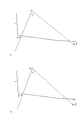
図15は、ガード付きキャブにおけるキャブ5内からの視野を示す模式図である。図15(a)は、従来のガード付きキャブにおけるキャブ5内からの視野を示す模式図である。従来のガード付きキャブは、図15(a)に示すように、管状の上枠140Cと、管状の下枠150Cとを有している。従来のガード付きキャブでは、キャブ5内に着座する運転員の視点EPを中心として、垂直方向における人の視野角は角度αである。   FIG. 15 is a schematic diagram showing a field of view from inside the cab 5 in the guarded cab. Fig.15 (a) is a schematic diagram which shows the visual field from the inside of the cab 5 in the conventional cab with a guard. The conventional guarded cab has a tubular upper frame 140C and a tubular lower frame 150C, as shown in FIG. In the conventional guarded cab, the viewing angle of the person in the vertical direction is an angle α around the viewpoint EP of the operator seated in the cab 5.

図15(b)は、実施形態のガード付きキャブ15におけるキャブ5内からの視野を示す模式図である。実施形態のガード付きキャブ15は、図15(b)に示すように、板材で形成されている上枠140と、管状の下枠150とを有している。図15(a)と比較して、フロントガード100の全体がキャブ5に近づけられて配置されており、下枠150は屈曲されているためにキャブ5により近づけられて配置されている。実施形態のガード付きキャブ15では、キャブ5内に着座する運転員の視点EPを中心として、垂直方向における人の視野角は角度βである。   FIG.15 (b) is a schematic diagram which shows the visual field from the inside of the cab 5 in the guarded cab 15 of embodiment. The guarded cab 15 according to the embodiment includes an upper frame 140 formed of a plate material and a tubular lower frame 150 as shown in FIG. Compared to FIG. 15A, the entire front guard 100 is disposed close to the cab 5, and the lower frame 150 is bent and disposed closer to the cab 5. In the guarded cab 15 according to the embodiment, the viewing angle of the person in the vertical direction is an angle β around the viewpoint EP of the operator seated in the cab 5.

図15(a)と図15(b)とを比較して、従来の視野角αよりも、実施形態における視野角βはより大きくなっている。たとえば視野角βは、視野角αよりも8%大きくなっている。したがって、実施形態のフロントガード100によって、フロントガード100の設けられたキャブ5内からの運転員の視野を拡大できることが示された。   15A and 15B, the viewing angle β in the embodiment is larger than the conventional viewing angle α. For example, the viewing angle β is 8% larger than the viewing angle α. Therefore, it was shown that the field of view of the operator from inside the cab 5 provided with the front guard 100 can be expanded by the front guard 100 of the embodiment.

また図5〜7に示すように、フレーム130の上枠140は、幅広部141,142を両端に有しており、幅広部141,142より幅の狭い幅狭部143を中央部分に有している。幅広部141,142と幅狭部143とを比較して、幅広部141,142は相対的に幅が広く、幅狭部143は相対的に幅が狭く形成されている。   5-7, the upper frame 140 of the frame 130 has wide portions 141 and 142 at both ends, and has a narrow portion 143 narrower than the wide portions 141 and 142 in the central portion. ing. Comparing the wide portions 141, 142 and the narrow portion 143, the wide portions 141, 142 are relatively wide and the narrow portion 143 is relatively narrow.

このようにすれば、幅広部141に右縦枠160の上端部167を溶接し、幅広部142に左縦枠170の上端部177を溶接することが可能になる。右縦枠160および左縦枠170を上枠140の両端の幅広部141,142にそれぞれ固定して、枠体が形成される。したがって、フレーム130の生産性を向上できるとともに、フレーム130の強度を確保することができる。   In this way, the upper end portion 167 of the right vertical frame 160 can be welded to the wide portion 141, and the upper end portion 177 of the left vertical frame 170 can be welded to the wide portion 142. The right vertical frame 160 and the left vertical frame 170 are respectively fixed to the wide portions 141 and 142 at both ends of the upper frame 140 to form a frame. Therefore, the productivity of the frame 130 can be improved and the strength of the frame 130 can be secured.

中央部分の幅狭部143を、両端の幅広部141,142より幅を狭く形成することにより、幅狭部143が運転員の上方の視界をさらに妨げにくくなるため、フロントガード100の設けられたキャブ5内からの運転員の視野をさらに拡大することができる。   Since the narrow portion 143 in the center portion is formed to be narrower than the wide portions 141 and 142 at both ends, the narrow portion 143 is more difficult to obstruct the field of view above the driver, and thus the front guard 100 is provided. The operator's field of view from within the cab 5 can be further expanded.

上枠140は、キャブ5内に着座した運転員から離れた位置に配置されるので、上枠140を管材でなく板材で形成しても、フロントガード100に要求される強度を十分に確保することが可能である。図7に示すように、細板材を長手方向に沿って折り曲げた形状に上枠140を構成することで、上枠140の強度をより向上できるので、フロントガード100の強度を確実に確保することができる。   Since the upper frame 140 is disposed at a position away from the operator seated in the cab 5, even if the upper frame 140 is formed of a plate material instead of a pipe material, sufficient strength required for the front guard 100 is ensured. It is possible. As shown in FIG. 7, since the strength of the upper frame 140 can be further improved by configuring the upper frame 140 in a shape obtained by bending a thin plate material along the longitudinal direction, the strength of the front guard 100 can be reliably ensured. Can do.

また図2〜4に示すように、下枠150と、右縦枠160と、左縦枠170とは、パイプで形成されている。下枠150と、右縦枠160と、左縦枠170とをパイプで形成することにより、上枠140を板材で形成しても、要求される強度を十分に確保したフロントガード100を容易に実現することができる。   Moreover, as shown in FIGS. 2-4, the lower frame 150, the right vertical frame 160, and the left vertical frame 170 are formed with the pipe. By forming the lower frame 150, the right vertical frame 160, and the left vertical frame 170 with pipes, the front guard 100 that sufficiently secures the required strength can be easily obtained even when the upper frame 140 is formed with a plate material. Can be realized.

また図4に示すように、右縦枠160には、複数のボルト装着部168が設けられている。ボルト装着部168は、ヒンジ部320およびブラケット310と共に、フロントガード100をキャブ5に取り付ける取付部を構成している。右縦枠160は、下枠150に連結される下端部166を有している。二箇所のボルト装着部168のうち、下側のボルト装着部168よりも下端部166に近い位置に、縦枠屈曲部161が形成されている。   As shown in FIG. 4, the right vertical frame 160 is provided with a plurality of bolt mounting portions 168. The bolt mounting part 168 constitutes an attachment part for attaching the front guard 100 to the cab 5 together with the hinge part 320 and the bracket 310. The right vertical frame 160 has a lower end portion 166 connected to the lower frame 150. Of the two bolt mounting portions 168, the vertical frame bent portion 161 is formed at a position closer to the lower end portion 166 than the lower bolt mounting portion 168.

このようにすれば、ボルト装着部168の設けられている中央枠部分164とキャブ5の前面との間に、取付部を配置するためのスペースを十分に確保することができる。右縦枠160のうち、取付部の配置のためのスペースを確保する必要のない部分を屈曲させてキャブ5に近づけて配置することにより、キャブ5内からの運転員の視野を拡大することができる。   In this way, a sufficient space for arranging the mounting portion can be secured between the central frame portion 164 provided with the bolt mounting portion 168 and the front surface of the cab 5. By bending a portion of the right vertical frame 160 that does not require a space for the placement of the mounting portion and bending it closer to the cab 5, the operator's field of view from within the cab 5 can be expanded. it can.

また図4に示すように、フロントガード100をキャブ5に取り付ける取付部は、ヒンジ部320を有している。図12に示すように、フロントガード100は、ヒンジ部320を回転中心としてキャブに対し相対回転する。これにより、フロントガード100を容易に開閉することができるので、キャブ5の前窓の清掃など、ガード付きキャブ15のメンテナンス性を向上することができる。   As shown in FIG. 4, the attachment portion for attaching the front guard 100 to the cab 5 has a hinge portion 320. As shown in FIG. 12, the front guard 100 rotates relative to the cab about the hinge portion 320 as a rotation center. Thereby, since the front guard 100 can be opened and closed easily, the maintainability of the guarded cab 15 such as cleaning of the front window of the cab 5 can be improved.

フレーム130の右縦枠160にヒンジ部320を有する取付部が設けられ、一方、フレーム130の左縦枠170には、図10,11に示すように、フロントガード100を閉状態にロックするロック装置が設けられている。   A mounting portion having a hinge portion 320 is provided on the right vertical frame 160 of the frame 130. On the other hand, the left vertical frame 170 of the frame 130 has a lock for locking the front guard 100 in a closed state as shown in FIGS. A device is provided.

左縦枠170には、図3に示すように、複数のピン挿通部181,182が設けられている。ピン挿通部181,182は、ピン止め部220およびブラケット210と共に、ロック装置を構成している。左縦枠170は、下枠150に連結される下端部176を有している。二箇所のピン挿通部181,182のうち、下側のピン挿通部182よりも下端部176に近い位置に、縦枠屈曲部171が形成されている。   As shown in FIG. 3, the left vertical frame 170 is provided with a plurality of pin insertion portions 181 and 182. The pin insertion parts 181 and 182 together with the pin fixing part 220 and the bracket 210 constitute a locking device. The left vertical frame 170 has a lower end 176 connected to the lower frame 150. Of the two pin insertion portions 181 and 182, a vertical frame bent portion 171 is formed at a position closer to the lower end portion 176 than the lower pin insertion portion 182.

このようにすれば、ピン挿通部181,182の設けられている中央枠部分174とキャブ5の前面との間に、ロック装置を配置するためのスペースを十分に確保することができる。左縦枠170のうち、ロック装置の配置のためのスペースを確保する必要のない部分を屈曲させてキャブ5に近づけて配置することにより、キャブ5内からの運転員の視野を拡大することができる。   In this way, a sufficient space for placing the locking device can be secured between the central frame portion 174 provided with the pin insertion portions 181 and 182 and the front surface of the cab 5. It is possible to enlarge the operator's field of view from within the cab 5 by bending a portion of the left vertical frame 170 that does not need to secure a space for the arrangement of the locking device and bending the portion close to the cab 5. it can.

フレーム130の一対の縦枠のうち、作業機4からより離れている左縦枠170において、キャブ5に対するフロントガード100のロックおよびロック解除が切り換えられる。図1に示すように、左縦枠170は、右縦枠160と比較して、旋回フレーム10の側縁により近い位置に配置されている。そのため、左縦枠170においてフロントガード100のロックおよびロック解除を切り換えるようにすれば、ロック作業およびロック解除作業をより容易に行なうことができる。   Of the pair of vertical frames of the frame 130, the front guard 100 is locked and unlocked with respect to the cab 5 in the left vertical frame 170 that is further away from the work machine 4. As shown in FIG. 1, the left vertical frame 170 is disposed closer to the side edge of the turning frame 10 than the right vertical frame 160. Therefore, if the lock and unlocking of the front guard 100 are switched in the left vertical frame 170, the locking operation and the unlocking operation can be performed more easily.

運転員がフロントガード100を開状態にしてキャブ5の前窓を清掃するとき、運転員は履帯2aの上に乗って作業をする。そのため、右縦枠160に設けたヒンジ部320を中心にフロントガード100が回転するようにすれば、開状態のフロントガード100が運転員の作業の妨げとなることがなく、作業性をより向上することができる。   When the operator cleans the front window of the cab 5 with the front guard 100 open, the operator gets on the crawler belt 2a to work. Therefore, if the front guard 100 rotates around the hinge portion 320 provided in the right vertical frame 160, the opened front guard 100 does not hinder the work of the operator, and the workability is further improved. can do.

また図8,9に示すように、フロントガード100の下枠150は、下枠屈曲部151を有している。下枠150は、下枠屈曲部151から右縦枠160に近づくにつれて、キャブ5に向かって後方に延びている。   As shown in FIGS. 8 and 9, the lower frame 150 of the front guard 100 has a lower frame bent portion 151. The lower frame 150 extends rearward toward the cab 5 as it approaches the right vertical frame 160 from the lower frame bent portion 151.

このようにすれば、下枠150の中央枠部分154とキャブ5の前面との間に、ワイパー400を配置するためのスペースを十分に確保することができる。下枠150のうち、ワイパー400の配置のためのスペースを確保する必要のない部分を屈曲させてキャブ5に近づけて配置することにより、キャブ5内からの運転員の視野を拡大することができる。   In this way, a sufficient space for arranging the wiper 400 can be secured between the central frame portion 154 of the lower frame 150 and the front surface of the cab 5. By bending a portion of the lower frame 150 that does not need to secure a space for the wiper 400 and placing it close to the cab 5, the operator's field of view from within the cab 5 can be expanded. .

一方、ガード付きキャブ15がワイパーを備えていない場合には、図13,14に示すように、下枠150に下枠屈曲部を形成せず、下枠150を直管形状にすることができる。これにより、下枠150の全体をキャブ5に近づけて配置することができるので、キャブ5内からの運転員の視野を一層拡大することができる。   On the other hand, when the guarded cab 15 does not include a wiper, as shown in FIGS. 13 and 14, the lower frame 150 can be formed into a straight pipe shape without forming the lower frame bent portion in the lower frame 150. . As a result, the entire lower frame 150 can be disposed close to the cab 5, so that the operator's field of view from within the cab 5 can be further expanded.

なお上記の実施形態では、複数の第1板部材110および複数の第2板部材120によって格子が形成され、この格子をフレーム130が取り囲むフロントガード100について説明した。実施形態のフロントガード100は、高い強度を有し、ISO(International Organization for Standardization)10262に定められている運転員保護ガードの特性を評価するための性能要求事項のうち、レベルIIの許容基準を満たすことができる。この構成に限られず、上述したフレーム130に係る特徴は、ISO10262に定められるレベルIの許容基準を満たす運転員保護ガードに適用されてもよい。たとえば、運転員保護ガードは、上述したフレームに網体が組み付けられて構成されてもよい。   In the above-described embodiment, the front guard 100 in which a grid is formed by the plurality of first plate members 110 and the plurality of second plate members 120 and the frame 130 surrounds the grid has been described. The front guard 100 according to the embodiment has high strength, and among the performance requirements for evaluating the characteristics of the operator protection guard defined in ISO (International Organization for Standardization) 10262, the level II acceptance criteria. Can be satisfied. The feature relating to the frame 130 described above is not limited to this configuration, and may be applied to an operator protection guard that satisfies the level I tolerance standard defined in ISO10262. For example, the operator protection guard may be configured by assembling a net body on the above-described frame.

また上記の実施形態では、図1に示すように、旋回体3の前方左側に配置されたガード付きキャブ15の右側に作業機4が配置されている例について説明した。ガード付きキャブ15と作業機4との配置は図1に示す例に限られるものではなく、旋回体3の前方右側に配置されたガード付きキャブ15の左側に作業機4が設けられていてもよい。この場合には、フレーム130の一対の縦枠のうち作業機4に近い左縦枠170が、縦枠屈曲部171から下枠150に近づくにつれてキャブ5に向かって後方に延びていることにより、運転員がキャブ5内からバケット4cを見やすくなる効果を、同様に得ることができる。   In the above embodiment, as shown in FIG. 1, the example in which the work implement 4 is arranged on the right side of the guarded cab 15 arranged on the left side in front of the revolving structure 3 has been described. The arrangement of the guarded cab 15 and the work implement 4 is not limited to the example shown in FIG. 1, and the work implement 4 may be provided on the left side of the guarded cab 15 arranged on the front right side of the revolving structure 3. Good. In this case, among the pair of vertical frames of the frame 130, the left vertical frame 170 close to the work machine 4 extends rearward toward the cab 5 as it approaches the lower frame 150 from the vertical frame bent portion 171. The effect that the operator can easily see the bucket 4c from the cab 5 can be obtained in the same manner.

今回開示された実施の形態はすべての点で例示であって制限的なものではないと考えられるべきである。本発明の範囲は上記した説明ではなくて請求の範囲によって示され、請求の範囲と均等の意味および範囲内でのすべての変更が含まれることが意図される。   The embodiment disclosed this time should be considered as illustrative in all points and not restrictive. The scope of the present invention is defined by the terms of the claims, rather than the description above, and is intended to include any modifications within the scope and meaning equivalent to the terms of the claims.

1 油圧ショベル、2 走行体、2a 履帯、3 旋回体、4 作業機、4a ブーム、4b アーム、4c バケット、5 キャブ、10 旋回フレーム、15 ガード付きキャブ、100 フロントガード、110 第1板部材、120 第2板部材、130 フレーム、140 上枠、141,142 幅広部、143 幅狭部、144 第一板部、145 第二板部、146 突出部、147 スリット、148 屈曲部、150 下枠、151,152 下枠屈曲部、153 右枠部分、154,164,174 中央枠部分、155 左枠部分、160 右縦枠、161,162,171,172 縦枠屈曲部、163,173 下枠部分、165,175 上枠部分、166,176 下端部、167,177 上端部、168 ボルト装着部、170 左縦枠、181,182,222,224 ピン挿通部、210,310 ブラケット、211,212 板部、214 貫通孔、215,217,227 ボルト、216 ストッパ固定部、218 ストッパ、220 ピン止め部、221 本体部、222,224 ピン挿通部、223,225 ピン挿通穴、230 ピン、320 ヒンジ部、400 ワイパー、EP 視点。   DESCRIPTION OF SYMBOLS 1 Hydraulic excavator, 2 traveling body, 2a crawler belt, 3 revolving structure, 4 working machine, 4a boom, 4b arm, 4c bucket, 5 cab, 10 revolving frame, 15 cab with guard, 100 front guard, 110 1st plate member, 120 Second plate member, 130 frame, 140 Upper frame, 141, 142 Wide part, 143 Narrow part, 144 First plate part, 145 Second plate part, 146 Projection part, 147 Slit, 148 Bent part, 150 Lower frame 151, 152 Lower frame bent part, 153 Right frame part, 154, 164, 174 Center frame part, 155 Left frame part, 160 Right vertical frame, 161, 162, 171, 172 Vertical frame bent part, 163, 173 Lower frame Part, 165, 175 upper frame part, 166, 176 lower end part, 167, 177 upper end part, 168 bolt mounting part, 170 Left vertical frame, 181, 182, 222, 224 Pin insertion part, 210, 310 Bracket, 211, 212 Plate part, 214 Through hole, 215, 217, 227 Bolt, 216 Stopper fixing part, 218 Stopper, 220 Pin fixing part, 221 body part, 222,224 pin insertion part, 223,225 pin insertion hole, 230 pin, 320 hinge part, 400 wiper, EP viewpoint.

Claims (7)

作業機と、
前記作業機の側方に配置されたキャブと、
前記キャブの前方に設けられた運転員保護ガードとを備え、
前記運転員保護ガードは、前記運転員保護ガードの外縁を構成する枠体を含み、
前記枠体は、上枠と、下枠と、右縦枠と、左縦枠とを有し、前記上枠と前記下枠と前記右縦枠と前記左縦枠とが枠組みされて形成されており、
前記右縦枠と前記左縦枠とのうち前記作業機に近い一方の縦枠は、縦枠屈曲部を有し、前記縦枠屈曲部から前記下枠に近づくにつれて前記キャブに向かって後方に延びており
前記一方の縦枠に、前記運転員保護ガードを前記キャブに取り付ける複数の取付部が設けられ、
前記一方の縦枠は、前記下枠に連結される下端部を有し、
最も下側の前記取付部よりも前記下端部に近い位置に前記縦枠屈曲部が形成される、作業車両。
A working machine,
A cab arranged on the side of the working machine;
An operator protection guard provided in front of the cab,
The operator protection guard includes a frame that forms an outer edge of the operator protection guard,
The frame includes an upper frame, a lower frame, a right vertical frame, and a left vertical frame, and is formed by framing the upper frame, the lower frame, the right vertical frame, and the left vertical frame. And
One of the right vertical frame and the left vertical frame, which is close to the work implement, has a vertical frame bent portion, and rearward toward the cab as it approaches the lower frame from the vertical frame bent portion. It extends and,
The one vertical frame is provided with a plurality of attachment portions for attaching the operator protection guard to the cab,
The one vertical frame has a lower end connected to the lower frame,
A work vehicle in which the vertical frame bent portion is formed at a position closer to the lower end portion than the lowermost attachment portion .
前記上枠は、板材で形成されている、請求項1に記載の作業車両。   The work vehicle according to claim 1, wherein the upper frame is formed of a plate material. 前記上枠は、幅広部を両端に有し、前記幅広部より幅の狭い幅狭部を中央部分に有する、請求項2に記載の作業車両。   The work vehicle according to claim 2, wherein the upper frame has a wide portion at both ends, and a narrow portion narrower than the wide portion at a central portion. 前記下枠と、前記右縦枠と、前記左縦枠とは、パイプで形成されている、請求項2に記載の作業車両。   The work vehicle according to claim 2, wherein the lower frame, the right vertical frame, and the left vertical frame are formed of pipes. 前記取付部は、ヒンジ構造を有し、前記運転員保護ガードは前記ヒンジ構造を回転中心として前記キャブに対し相対回転する、請求項に記載の作業車両。 The work vehicle according to claim 1 , wherein the attachment portion has a hinge structure, and the operator protection guard rotates relative to the cab with the hinge structure as a rotation center. 前記下枠は、下枠屈曲部を有し、前記下枠屈曲部から前記一方の縦枠に近づくにつれて前記キャブに向かって後方に延びている、請求項1〜のいずれか1項に記載の作業車両。 The lower frame has a lower frame bent portions, closer to the vertical frame of the one from the lower frame bent portions extend rearwardly toward the cab, according to any one of claims 1 to 5 Work vehicle. 作業機械のキャブの前方に設けられる運転員保護ガードにおいて、
前記運転員保護ガードの外縁を構成する枠体を備え、
前記枠体は、
板材で形成されている上枠と、
パイプで形成されている下枠と、
パイプで形成されており、少なくともいずれか一方が縦枠屈曲部を有する、右縦枠および左縦枠とを有
前記右縦枠および前記左縦枠のうち、前記縦枠屈曲部を有する一方の縦枠に、前記運転員保護ガードを前記キャブに取り付ける複数の取付部が設けられ、
前記一方の縦枠は、前記下枠に連結される下端部を有し、
最も下側の前記取付部よりも前記下端部に近い位置に前記縦枠屈曲部が形成される、運転員保護ガード。
In the operator protection guard provided in front of the cab of the work machine,
Comprising a frame constituting the outer edge of the operator protection guard;
The frame is
An upper frame formed of a plate material;
A lower frame formed of pipes,
Pipe is formed by, possess at least one has a vertical frame bent portion, and a right vertical frame and left vertical frame,
Among the right vertical frame and the left vertical frame, one vertical frame having the vertical frame bent portion is provided with a plurality of attachment portions for attaching the operator protection guard to the cab,
The one vertical frame has a lower end connected to the lower frame,
The operator protection guard in which the vertical frame bent portion is formed at a position closer to the lower end portion than the lowermost attachment portion .
JP2014561614A 2014-12-11 2014-12-11 Work vehicle and operator protection guard Expired - Fee Related JP5827762B1 (en)

Applications Claiming Priority (1)

Application Number Priority Date Filing Date Title
PCT/JP2014/082783 WO2015087950A1 (en) 2014-12-11 2014-12-11 Work vehicle and operator protective guard

Publications (2)

Publication Number Publication Date
JP5827762B1 true JP5827762B1 (en) 2015-12-02
JPWO2015087950A1 JPWO2015087950A1 (en) 2017-03-16

Family

ID=53371249

Family Applications (1)

Application Number Title Priority Date Filing Date
JP2014561614A Expired - Fee Related JP5827762B1 (en) 2014-12-11 2014-12-11 Work vehicle and operator protection guard

Country Status (7)

Country Link
US (1) US9441343B2 (en)
JP (1) JP5827762B1 (en)
KR (1) KR101690436B1 (en)
CN (1) CN104903518B (en)
DE (1) DE112014000177B4 (en)
IN (1) IN2015DN01657A (en)
WO (1) WO2015087950A1 (en)

Families Citing this family (5)

* Cited by examiner, † Cited by third party
Publication number Priority date Publication date Assignee Title
US20150123428A1 (en) * 2012-06-18 2015-05-07 Volvo Construction Equipment Ab Cab protection apparatus for construction machinery
IN2015DN01656A (en) * 2014-12-11 2015-08-14 Komatsu Mfg Co Ltd
JP7214519B2 (en) 2019-03-15 2023-01-30 株式会社クボタ Front guard and working machine
IT202000002671A1 (en) * 2020-02-11 2021-08-11 Cnh Ind Italia Spa WORK VEHICLE EQUIPPED WITH AN IMPROVED SOLAR PANEL ASSEMBLY
CN111335394B (en) * 2020-03-13 2022-01-28 三一重机有限公司 Adjusting method and adjusting device for front protecting net grating of excavator and excavator

Citations (4)

* Cited by examiner, † Cited by third party
Publication number Priority date Publication date Assignee Title
JPH0687457U (en) * 1993-06-03 1994-12-22 新キャタピラー三菱株式会社 Lifting cab of construction machinery
JP2001097250A (en) * 1999-09-30 2001-04-10 Takahashiworks Co Ltd Protector of cab
JP2002194773A (en) * 2000-12-26 2002-07-10 Hitachi Constr Mach Co Ltd Cab for construction machinery
WO2011025874A1 (en) * 2009-08-27 2011-03-03 Adc Custom, Llc Quick attach riser for cabin protection structure

Family Cites Families (5)

* Cited by examiner, † Cited by third party
Publication number Priority date Publication date Assignee Title
KR100464734B1 (en) 2001-12-18 2005-01-05 볼보 컨스트럭션 이키프먼트 홀딩 스웨덴 에이비 An apparatus equiped in driving room that supports driver's protector
JP5541302B2 (en) * 2012-03-01 2014-07-09 コベルコ建機株式会社 Construction machine front guard device
CN202627058U (en) 2012-06-13 2012-12-26 徐州博汇驾驶室制造有限公司 Excavator cab with protective structure
US20150123428A1 (en) 2012-06-18 2015-05-07 Volvo Construction Equipment Ab Cab protection apparatus for construction machinery
JP5355831B1 (en) 2013-03-29 2013-11-27 株式会社小松製作所 Operator protection guard, guarded work machine cab, and work machine

Patent Citations (4)

* Cited by examiner, † Cited by third party
Publication number Priority date Publication date Assignee Title
JPH0687457U (en) * 1993-06-03 1994-12-22 新キャタピラー三菱株式会社 Lifting cab of construction machinery
JP2001097250A (en) * 1999-09-30 2001-04-10 Takahashiworks Co Ltd Protector of cab
JP2002194773A (en) * 2000-12-26 2002-07-10 Hitachi Constr Mach Co Ltd Cab for construction machinery
WO2011025874A1 (en) * 2009-08-27 2011-03-03 Adc Custom, Llc Quick attach riser for cabin protection structure

Also Published As

Publication number Publication date
CN104903518A (en) 2015-09-09
JPWO2015087950A1 (en) 2017-03-16
CN104903518B (en) 2017-10-10
KR20160072069A (en) 2016-06-22
DE112014000177T5 (en) 2016-09-15
US20160168824A1 (en) 2016-06-16
IN2015DN01657A (en) 2015-08-14
DE112014000177B4 (en) 2017-04-06
KR101690436B1 (en) 2016-12-27
WO2015087950A1 (en) 2015-06-18
US9441343B2 (en) 2016-09-13

Similar Documents

Publication Publication Date Title
JP5827762B1 (en) Work vehicle and operator protection guard
JP5834152B2 (en) Cabs and excavators for guarded work vehicles
JP6919975B2 (en) Work machine cab retaining structure
JP5204911B1 (en) Bulldozer
JP5541302B2 (en) Construction machine front guard device
JP2010013095A (en) Operation cab for construction machine equipped with protective device
JP5353795B2 (en) Work machine
JP6988241B2 (en) Construction machinery
JP2019206846A (en) Cab for work machine, and work machine
JP7214519B2 (en) Front guard and working machine
JP4201186B2 (en) Wheeled construction machine
JP5054802B2 (en) Construction machinery
JP2020060015A (en) Cab and work machine
JP6171561B2 (en) Work machine
JP5873778B2 (en) Work machine
JP7039397B2 (en) Turning work vehicle
JP6079193B2 (en) Cab head guard device for construction machinery
JP7047648B2 (en) Locking device for construction machinery and positioning method for locking device
JP4295003B2 (en) Cab protection structure
JP4703369B2 (en) Work machine
JP6539615B2 (en) Small hydraulic shovel
JP6482925B2 (en) Working machine
JP2016102372A (en) Construction machine
WO2017060983A1 (en) Work vehicle and locking bar
JP2001163268A (en) Exterior cover device for apparatus equipped with engine

Legal Events

Date Code Title Description
A521 Written amendment

Free format text: JAPANESE INTERMEDIATE CODE: A523

Effective date: 20150903

TRDD Decision of grant or rejection written
A01 Written decision to grant a patent or to grant a registration (utility model)

Free format text: JAPANESE INTERMEDIATE CODE: A01

Effective date: 20151006

A61 First payment of annual fees (during grant procedure)

Free format text: JAPANESE INTERMEDIATE CODE: A61

Effective date: 20151016

R150 Certificate of patent or registration of utility model

Ref document number: 5827762

Country of ref document: JP

Free format text: JAPANESE INTERMEDIATE CODE: R150

LAPS Cancellation because of no payment of annual fees