JP5823980B2 - Composition of heat insulation device with poncho type patient clothes - Google Patents
Composition of heat insulation device with poncho type patient clothes Download PDFInfo
- Publication number
- JP5823980B2 JP5823980B2 JP2012545924A JP2012545924A JP5823980B2 JP 5823980 B2 JP5823980 B2 JP 5823980B2 JP 2012545924 A JP2012545924 A JP 2012545924A JP 2012545924 A JP2012545924 A JP 2012545924A JP 5823980 B2 JP5823980 B2 JP 5823980B2
- Authority
- JP
- Japan
- Prior art keywords
- patient
- inflatable
- warming
- convection
- garment
- Prior art date
- Legal status (The legal status is an assumption and is not a legal conclusion. Google has not performed a legal analysis and makes no representation as to the accuracy of the status listed.)
- Active
Links
- 238000009413 insulation Methods 0.000 title claims description 5
- PGOOBECODWQEAB-UHFFFAOYSA-N (E)-clothianidin Chemical compound [O-][N+](=O)\N=C(/NC)NCC1=CN=C(Cl)S1 PGOOBECODWQEAB-UHFFFAOYSA-N 0.000 title description 6
- 239000000203 mixture Substances 0.000 title description 3
- 238000010792 warming Methods 0.000 claims description 106
- 239000000463 material Substances 0.000 claims description 45
- 230000002093 peripheral effect Effects 0.000 claims description 6
- 238000002560 therapeutic procedure Methods 0.000 description 20
- 238000004519 manufacturing process Methods 0.000 description 17
- 238000001356 surgical procedure Methods 0.000 description 13
- 239000004743 Polypropylene Substances 0.000 description 10
- -1 polypropylene Polymers 0.000 description 10
- 229920001155 polypropylene Polymers 0.000 description 10
- 238000011282 treatment Methods 0.000 description 8
- 239000002131 composite material Substances 0.000 description 6
- 238000005304 joining Methods 0.000 description 6
- 238000010586 diagram Methods 0.000 description 5
- 238000000034 method Methods 0.000 description 5
- 235000019648 warmth Nutrition 0.000 description 5
- 238000005520 cutting process Methods 0.000 description 4
- 210000002414 leg Anatomy 0.000 description 4
- 230000035699 permeability Effects 0.000 description 4
- 210000001015 abdomen Anatomy 0.000 description 3
- 210000002683 foot Anatomy 0.000 description 3
- 238000012546 transfer Methods 0.000 description 3
- 206010021113 Hypothermia Diseases 0.000 description 2
- 229920001131 Pulp (paper) Polymers 0.000 description 2
- 238000004026 adhesive bonding Methods 0.000 description 2
- 210000003423 ankle Anatomy 0.000 description 2
- 238000000576 coating method Methods 0.000 description 2
- 238000010276 construction Methods 0.000 description 2
- 230000000694 effects Effects 0.000 description 2
- 210000001624 hip Anatomy 0.000 description 2
- 230000002631 hypothermal effect Effects 0.000 description 2
- 238000012802 pre-warming Methods 0.000 description 2
- 238000007669 thermal treatment Methods 0.000 description 2
- 238000002834 transmittance Methods 0.000 description 2
- 206010002091 Anaesthesia Diseases 0.000 description 1
- 241000272517 Anseriformes Species 0.000 description 1
- 206010016334 Feeling hot Diseases 0.000 description 1
- 241000144958 Piaractus mesopotamicus Species 0.000 description 1
- 238000001949 anaesthesia Methods 0.000 description 1
- 230000037005 anaesthesia Effects 0.000 description 1
- 230000005540 biological transmission Effects 0.000 description 1
- 230000015572 biosynthetic process Effects 0.000 description 1
- 239000011248 coating agent Substances 0.000 description 1
- 238000013461 design Methods 0.000 description 1
- 238000007599 discharging Methods 0.000 description 1
- 238000001125 extrusion Methods 0.000 description 1
- 230000004927 fusion Effects 0.000 description 1
- 238000003780 insertion Methods 0.000 description 1
- 230000037431 insertion Effects 0.000 description 1
- 238000002955 isolation Methods 0.000 description 1
- 238000012423 maintenance Methods 0.000 description 1
- 238000005259 measurement Methods 0.000 description 1
- 238000000465 moulding Methods 0.000 description 1
- 239000004745 nonwoven fabric Substances 0.000 description 1
- 230000037000 normothermia Effects 0.000 description 1
- 210000004197 pelvis Anatomy 0.000 description 1
- 230000000737 periodic effect Effects 0.000 description 1
- 239000004033 plastic Substances 0.000 description 1
- 229920000728 polyester Polymers 0.000 description 1
- 238000012545 processing Methods 0.000 description 1
- 230000005855 radiation Effects 0.000 description 1
- 230000001105 regulatory effect Effects 0.000 description 1
- 238000007789 sealing Methods 0.000 description 1
- 239000007779 soft material Substances 0.000 description 1
- 210000000689 upper leg Anatomy 0.000 description 1
- 238000003466 welding Methods 0.000 description 1
Images


Classifications
-
- A—HUMAN NECESSITIES
- A61—MEDICAL OR VETERINARY SCIENCE; HYGIENE
- A61F—FILTERS IMPLANTABLE INTO BLOOD VESSELS; PROSTHESES; DEVICES PROVIDING PATENCY TO, OR PREVENTING COLLAPSING OF, TUBULAR STRUCTURES OF THE BODY, e.g. STENTS; ORTHOPAEDIC, NURSING OR CONTRACEPTIVE DEVICES; FOMENTATION; TREATMENT OR PROTECTION OF EYES OR EARS; BANDAGES, DRESSINGS OR ABSORBENT PADS; FIRST-AID KITS
- A61F7/00—Heating or cooling appliances for medical or therapeutic treatment of the human body
- A61F7/02—Compresses or poultices for effecting heating or cooling
-
- A—HUMAN NECESSITIES
- A61—MEDICAL OR VETERINARY SCIENCE; HYGIENE
- A61F—FILTERS IMPLANTABLE INTO BLOOD VESSELS; PROSTHESES; DEVICES PROVIDING PATENCY TO, OR PREVENTING COLLAPSING OF, TUBULAR STRUCTURES OF THE BODY, e.g. STENTS; ORTHOPAEDIC, NURSING OR CONTRACEPTIVE DEVICES; FOMENTATION; TREATMENT OR PROTECTION OF EYES OR EARS; BANDAGES, DRESSINGS OR ABSORBENT PADS; FIRST-AID KITS
- A61F7/00—Heating or cooling appliances for medical or therapeutic treatment of the human body
- A61F2007/0001—Body part
- A61F2007/0018—Trunk or parts thereof
-
- A—HUMAN NECESSITIES
- A61—MEDICAL OR VETERINARY SCIENCE; HYGIENE
- A61F—FILTERS IMPLANTABLE INTO BLOOD VESSELS; PROSTHESES; DEVICES PROVIDING PATENCY TO, OR PREVENTING COLLAPSING OF, TUBULAR STRUCTURES OF THE BODY, e.g. STENTS; ORTHOPAEDIC, NURSING OR CONTRACEPTIVE DEVICES; FOMENTATION; TREATMENT OR PROTECTION OF EYES OR EARS; BANDAGES, DRESSINGS OR ABSORBENT PADS; FIRST-AID KITS
- A61F7/00—Heating or cooling appliances for medical or therapeutic treatment of the human body
- A61F2007/0059—Heating or cooling appliances for medical or therapeutic treatment of the human body with an open fluid circuit
- A61F2007/006—Heating or cooling appliances for medical or therapeutic treatment of the human body with an open fluid circuit of gas
-
- A—HUMAN NECESSITIES
- A61—MEDICAL OR VETERINARY SCIENCE; HYGIENE
- A61F—FILTERS IMPLANTABLE INTO BLOOD VESSELS; PROSTHESES; DEVICES PROVIDING PATENCY TO, OR PREVENTING COLLAPSING OF, TUBULAR STRUCTURES OF THE BODY, e.g. STENTS; ORTHOPAEDIC, NURSING OR CONTRACEPTIVE DEVICES; FOMENTATION; TREATMENT OR PROTECTION OF EYES OR EARS; BANDAGES, DRESSINGS OR ABSORBENT PADS; FIRST-AID KITS
- A61F7/00—Heating or cooling appliances for medical or therapeutic treatment of the human body
- A61F2007/0091—Heating or cooling appliances for medical or therapeutic treatment of the human body inflatable
-
- A—HUMAN NECESSITIES
- A61—MEDICAL OR VETERINARY SCIENCE; HYGIENE
- A61F—FILTERS IMPLANTABLE INTO BLOOD VESSELS; PROSTHESES; DEVICES PROVIDING PATENCY TO, OR PREVENTING COLLAPSING OF, TUBULAR STRUCTURES OF THE BODY, e.g. STENTS; ORTHOPAEDIC, NURSING OR CONTRACEPTIVE DEVICES; FOMENTATION; TREATMENT OR PROTECTION OF EYES OR EARS; BANDAGES, DRESSINGS OR ABSORBENT PADS; FIRST-AID KITS
- A61F7/00—Heating or cooling appliances for medical or therapeutic treatment of the human body
- A61F2007/0094—Heating or cooling appliances for medical or therapeutic treatment of the human body using a remote control
-
- A—HUMAN NECESSITIES
- A61—MEDICAL OR VETERINARY SCIENCE; HYGIENE
- A61F—FILTERS IMPLANTABLE INTO BLOOD VESSELS; PROSTHESES; DEVICES PROVIDING PATENCY TO, OR PREVENTING COLLAPSING OF, TUBULAR STRUCTURES OF THE BODY, e.g. STENTS; ORTHOPAEDIC, NURSING OR CONTRACEPTIVE DEVICES; FOMENTATION; TREATMENT OR PROTECTION OF EYES OR EARS; BANDAGES, DRESSINGS OR ABSORBENT PADS; FIRST-AID KITS
- A61F7/00—Heating or cooling appliances for medical or therapeutic treatment of the human body
- A61F7/02—Compresses or poultices for effecting heating or cooling
- A61F2007/0225—Compresses or poultices for effecting heating or cooling connected to the body or a part thereof
- A61F2007/0233—Compresses or poultices for effecting heating or cooling connected to the body or a part thereof connected to or incorporated in clothing or garments
- A61F2007/0234—Compresses or poultices for effecting heating or cooling connected to the body or a part thereof connected to or incorporated in clothing or garments for the upper part of the trunk, e.g. bodice
-
- A—HUMAN NECESSITIES
- A61—MEDICAL OR VETERINARY SCIENCE; HYGIENE
- A61F—FILTERS IMPLANTABLE INTO BLOOD VESSELS; PROSTHESES; DEVICES PROVIDING PATENCY TO, OR PREVENTING COLLAPSING OF, TUBULAR STRUCTURES OF THE BODY, e.g. STENTS; ORTHOPAEDIC, NURSING OR CONTRACEPTIVE DEVICES; FOMENTATION; TREATMENT OR PROTECTION OF EYES OR EARS; BANDAGES, DRESSINGS OR ABSORBENT PADS; FIRST-AID KITS
- A61F7/00—Heating or cooling appliances for medical or therapeutic treatment of the human body
- A61F7/02—Compresses or poultices for effecting heating or cooling
- A61F2007/0244—Compresses or poultices for effecting heating or cooling with layers
- A61F2007/0258—Compresses or poultices for effecting heating or cooling with layers with a fluid permeable layer
-
- A—HUMAN NECESSITIES
- A61—MEDICAL OR VETERINARY SCIENCE; HYGIENE
- A61F—FILTERS IMPLANTABLE INTO BLOOD VESSELS; PROSTHESES; DEVICES PROVIDING PATENCY TO, OR PREVENTING COLLAPSING OF, TUBULAR STRUCTURES OF THE BODY, e.g. STENTS; ORTHOPAEDIC, NURSING OR CONTRACEPTIVE DEVICES; FOMENTATION; TREATMENT OR PROTECTION OF EYES OR EARS; BANDAGES, DRESSINGS OR ABSORBENT PADS; FIRST-AID KITS
- A61F7/00—Heating or cooling appliances for medical or therapeutic treatment of the human body
- A61F7/02—Compresses or poultices for effecting heating or cooling
- A61F2007/0268—Compresses or poultices for effecting heating or cooling having a plurality of compartments being filled with a heat carrier
-
- A—HUMAN NECESSITIES
- A61—MEDICAL OR VETERINARY SCIENCE; HYGIENE
- A61F—FILTERS IMPLANTABLE INTO BLOOD VESSELS; PROSTHESES; DEVICES PROVIDING PATENCY TO, OR PREVENTING COLLAPSING OF, TUBULAR STRUCTURES OF THE BODY, e.g. STENTS; ORTHOPAEDIC, NURSING OR CONTRACEPTIVE DEVICES; FOMENTATION; TREATMENT OR PROTECTION OF EYES OR EARS; BANDAGES, DRESSINGS OR ABSORBENT PADS; FIRST-AID KITS
- A61F7/00—Heating or cooling appliances for medical or therapeutic treatment of the human body
- A61F7/02—Compresses or poultices for effecting heating or cooling
- A61F2007/0282—Compresses or poultices for effecting heating or cooling for particular medical treatments or effects
- A61F2007/0288—Compresses or poultices for effecting heating or cooling for particular medical treatments or effects during operations
-
- A—HUMAN NECESSITIES
- A61—MEDICAL OR VETERINARY SCIENCE; HYGIENE
- A61F—FILTERS IMPLANTABLE INTO BLOOD VESSELS; PROSTHESES; DEVICES PROVIDING PATENCY TO, OR PREVENTING COLLAPSING OF, TUBULAR STRUCTURES OF THE BODY, e.g. STENTS; ORTHOPAEDIC, NURSING OR CONTRACEPTIVE DEVICES; FOMENTATION; TREATMENT OR PROTECTION OF EYES OR EARS; BANDAGES, DRESSINGS OR ABSORBENT PADS; FIRST-AID KITS
- A61F7/00—Heating or cooling appliances for medical or therapeutic treatment of the human body
- A61F7/0097—Blankets with active heating or cooling sources
Description
(関連出願の相互参照)
本出願は、すべて本出願と所有者を同一にする以下の特許出願の対象に関する対象を含む。
(Cross-reference of related applications)
This application includes subject matter relating to the subject matter of the following patent applications, all of which have the same owner as the present application.
(発明の分野)
「Patient Comfort Appratus and System」の名称で2003年4月10日に出願され、2003年10月23日に公報第WO 2003/086500号として公開された、特許協力条約(PCT)出願第PCT/US03/11128号、
「Perioperative Warming Device」の名称で2005年7月18日に出願され、2006年2月23日に公報第WO 2006/020170号として公開された、特許協力条約(PCT)出願第PCT/US05/025355号、
「Warming Device with Varied Permeability」の名称で2005年12月6日に出願され、2006年6月15日に公報第WO 2006/062910号として公開された、特許協力条約(PCT)出願第PCT/US05/043968号、
「Warming Device」の名称で2005年12月6日に出願され、2006年6月15日に公報第WO 2006/063027号として公開された、特許協力条約(PCT)出願第PCT/US05/044214号、
「Warming Device for Perioperative Use」の名称で2006年2月9日に出願され、2006年8月17日に公報第WO 2006/086587号として公開された、特許協力条約(PCT)出願第PCT/US06/004644号、
「Patient Comfort Apparatus and System」の名称で2003年4月10日に出願され、2003年10月16日に公報第US 2003/195596号として公開され、2006年2月21日に特許第7,001,416号として交付された、米国特許出願第10/411,865号、
「Patient Comfort Apparatus and System」の名称で2004年9月20日に出願され、2005年6月30日に公報第US 2005/0143796号として公開された、米国特許出願第10/508,319号、
「Warming Device with Varied Permeability」の名称で2004年12月7日に出願され、2006年6月8日に公報第US 2006/0122671号として公開された、米国特許出願第11/005,883号、
「Warming Device」の名称で2004年12月7日に出願され、2006年6月8日に公報第US 2006/0122672号として公開された、米国特許出願第11/006,491号、
「Perioperative Warming Device」の名称で2005年2月11日に出願され、2006年8月17日に公報第US 2006/0184215号として公開された、米国特許出願第11/057,396号、
「Warming Device for Perioperative Use」の名称で2005年2月11日に出願され、2006年8月17日に公報第US 2006/0184217号として公開された、米国特許出願第11/057,403号、
「Clinical Garment for Comfort Warming and Prewarming」の名称で2005年2月11日に出願され、2006年8月17日に公報第US 2006/0184218号として公開された、米国特許出願第11/057,404号、及び
「Forced Air Warming Unit」の名称で2006年2月27日に出願され、2006年7月6日に公報第US2006/0147320号として公開された、米国特許出願第11/363,136号。
(Field of Invention)
Patent Cooperation Treaty (PCT) Application No. PCT / US03, filed on April 10, 2003 under the name “Patient Comfort Apparatus and System” and published as Publication No. WO 2003/086500 on October 23, 2003 / 11128,
Patent Cooperation Treaty (PCT) Application No. PCT / US05 / 025355, filed July 18, 2005 under the name “Perioperive Warming Device” and published as publication No. WO 2006/020170 on February 23, 2006. issue,
Patent Cooperation Treaty (PCT) Application No. PCT / US05, filed on December 6, 2005 under the name “Warming Device with Varied Permeability” and published as Publication No. WO 2006/062910 on June 15, 2006. / 043968,
Patent Cooperation Treaty (PCT) Application No. PCT / US05 / 044214, filed on December 6, 2005 under the name “Warming Device” and published as Publication No. WO 2006/063027 on June 15, 2006. ,
Patent Cooperation Treaty (PCT) Application No. PCT / US06, filed February 9, 2006 under the name “Warming Device for Peripheral Use” and published as publication No. WO 2006/08587 on August 17, 2006. / 004644,
It was filed on April 10, 2003 under the name “Patience Comfort Apparatus and System”, published on October 16, 2003 as publication No. US 2003/195596, and on February 21, 2006, Patent No. 7,001. , 416, U.S. Patent Application No. 10 / 411,865,
United States Patent Application No. 10 / 508,319, filed September 20, 2004 under the name “Patience Comfort Apparatus and System” and published as publication No. US 2005/0143796 on June 30, 2005;
US patent application Ser. No. 11 / 005,883, filed Dec. 7, 2004 under the name “Warming Device with Varied Permeability” and published as publication No. US 2006/0122671 on Jun. 8, 2006;
US patent application Ser. No. 11 / 006,491, filed Dec. 7, 2004 under the name “Warming Device” and published as publication No. US 2006/0122672 on Jun. 8, 2006;
US patent application Ser. No. 11 / 057,396, filed on Feb. 11, 2005 under the name “Perioperive Warming Device” and published as publication No. US 2006/0184215 on Aug. 17, 2006;
United States Patent Application No. 11 / 057,403, filed February 11, 2005 under the name “Warming Device for Periodic Use,” and published as publication US 2006/0184217 on August 17, 2006;
U.S. Patent Application No. 11 / 057,404, filed February 11, 2005 under the name "Clinical Garment for Comfort Warming and Prewarming" and published as publication No. US 2006/0184218 on August 17, 2006. And US patent application Ser. No. 11 / 363,136 filed Feb. 27, 2006 under the name “Forced Air Warming Unit” and published as publication No. US 2006/0147320 on Jul. 6, 2006. .
臨床環境において患者を保温するための装置に、患者服上に支持された膨張式対流保温器を備えるポンチョ型患者服が含まれる。 An apparatus for warming a patient in a clinical environment includes a poncho-type patient garment with an inflatable convection warmer supported on the patient garment.
対流によって人体に熱を伝達する膨張式保温毛布は公知である。この場合、保温毛布は加圧・加温された空気の流れを受け、この加圧空気に応じて膨張し、加温された空気を空気圧構造体内に行き渡らせ、かつその加温された空気を身体上に放出することによって、快適さの向上、悪寒の抑制、及び低体温症の治療・予防などの目的を達成する。本出願人、Arizant Healthcare Inc.は、BAIR HUGGER(登録商標)のブランド名で、このような膨張式保温毛布を販売している。 Inflatable thermal blankets that transfer heat to the human body by convection are known. In this case, the thermal blanket receives the flow of pressurized and heated air, expands in response to the pressurized air, spreads the heated air into the pneumatic structure, and removes the heated air. By releasing it on the body, it achieves the purpose of improving comfort, suppressing chills, and treating and preventing hypothermia. Applicant, Arizant Healthcare Inc. Sells such inflatable thermal blankets under the brand name BAIR HUGGER®.
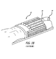
膨張式保温毛布は、保温治療の指示がなされる場合のような特殊な配置のために特別に設計される。先行技術において公知である3つの代表的な膨張式保温毛布を図1A〜1Dに示す。「全身用」膨張式保温毛布10を図1Aに示す。この全身用毛布10は、患者上に位置し、患者の身体に沿って長手方向に延在することで実質的に患者の全身、つまりくるぶし又は足の近くから首までを覆うように構成されている。図1Bに示される「下半身用」保温毛布12は、患者上に位置し、患者の身体に沿って長手方向に延在することで患者の下半身、つまりくるぶし又は足の近くから腰のくびれ(ウエスト)又は骨盤までを覆うように構成されている。「上半身用」保温毛布15を図1C及び1Dに例示する。加温・加圧された空気の流れが供給されると、各保温毛布10、12、15は膨張し、それ自体の内部に空気を行き渡らせる。保温毛布が患者上にある間に、加温・加圧された空気の流れが、保温毛布の患者に面する通気性表面内の開口又は隙間を通して流れる。これらの保温毛布は1つ又は2つ以上の吸気口18を有してもよく、この吸気口を通して、空気ホース19がヒータ/ブロワユニット(これらの図には示されていない)から加温・加圧された空気を供給する。
Inflatable thermal blankets are specially designed for special arrangements, such as when thermal therapy instructions are given. Three representative inflatable thermal blankets known in the prior art are shown in FIGS. A “whole body” inflatable
これらの先行技術の膨張式加温毛布の構成はよく理解されている。具体的な構成例は、米国特許第5,620,482号、同第5,443,488号、同第5,360,439号、及び同第5,304,213号に記載されている。また、米国特許第5,974,605号も参照されたい。 The construction of these prior art inflatable warming blankets is well understood. Specific configuration examples are described in US Pat. Nos. 5,620,482, 5,443,488, 5,360,439, and 5,304,213. See also US Pat. No. 5,974,605.
図1A〜1Dの膨張式保温毛布は、臨床応用範囲が狭い。すなわち、これらは手術中及び手術後の期間において臥位の患者に対して機能するように設計され構成されている。これらの毛布は、これらを患者の身体上に支持するための手立てなしには、手術前において直立又は立位の患者に対して使用することはできない。更に、立位又は座位の患者に対して縦方向に配置・操作される場合には、毛布が患者の周りを覆うことができないために、保温毛布により放出される加温された空気の多くが失われてしまう。 1A-1D has a narrow clinical application range. That is, they are designed and configured to function for patients in a supine position during and after surgery. These blankets cannot be used on an upright or standing patient prior to surgery without a means to support them on the patient's body. In addition, when placed and manipulated vertically with respect to a standing or sitting patient, much of the warmed air released by the warming blanket is lost because the blanket cannot cover the patient. It will be lost.
立位、座位、又は臥位にあり得る患者を保温する問題を解決する新規の装置が、参照の特許出願公開第US 2005/0143796号に開示されており、その内容は参照することにより本明細書に組み込まれる。この保温装置は、膨張式対流保温器を支持することで臨床服の着用者を保温するように構成された臨床服を含み、それによって、着用者の可動性を制限することなしに着用者に快適さをもたらす。手術中に使用するための新規な多機能保温装置が、参照の特許出願公開第US 2006/0122671号に開示されており、その内容は参照することにより本明細書に組み込まれる。この多機能保温装置は、臨床服と、この臨床服の面上に支持される、快適保温及び/又は保温治療のために構成された膨張式対流保温器とからなる。 A novel device that solves the problem of warming a patient who may be in a standing, sitting or lying position is disclosed in the referenced patent application publication US 2005/0143796, the contents of which are hereby incorporated by reference. Embedded in the book. The warming device includes a clinical garment configured to warm the wearer of the clinical garment by supporting an inflatable convection warmer, thereby providing the wearer with no limitation on the wearer's mobility. Bring comfort. A novel multifunctional warming device for use during surgery is disclosed in the referenced patent application publication US 2006/0122671, the contents of which are hereby incorporated by reference. The multi-functional warmer comprises a clinical garment and an inflatable convection warmer configured for comfortable warming and / or thermal therapy supported on the surface of the clinical garment.
Arizant Healthcare Inc.によりBAIR PAWS(登録商標)のブランド名で製造・販売される患者保温装置は、臨床服と、この臨床服の1つ以上の面上に支持される1つ以上の膨張式対流保温器とを含む。 Arizant Healthcare Inc. Manufactured and sold by BAIR PAWS® under the brand name of a clinical clothing and one or more inflatable convection warmers supported on one or more sides of the clinical clothing. Including.
これらの患者保温装置の構成は、段落[0002]に参照の公開済み特許出願及び交付済み特許に詳細に開示されている。患者が臨床服を着用中に、臨床服の内面上に支持された対流保温器が加温・加圧された空気の流れによって膨らみ、加温された空気を臨床服の内部に放出し、手術前の段階において快適保温をもたらす。この患者保温装置は患者上に配置され、操作されることによって、手術中及び手術後に保温治療を提供する。臨床服は袖を有するローブのような衣服で、柔らかい不織布材からなる。この臨床服は、紐によって閉じられる後部又は側部開口を有する。袖は、臨床服の身頃が形成された後に臨床服上に縫い付けられるが、この袖は、上部の継目に沿って開き、また再度閉じることが可能であり、これによって臨床服を着用している患者の上腕及び胸部に接触することができるようになっている。患者服は手術中及び手術後に、開き、患者から除去し、また患者上に再配置することができ、これによって上半身、全身、又は下半身の保温治療を行うことが可能となる。このような構成により、周術サイクルの全期間にわたって、臨床的に効果的な保温策が提供される。 The configuration of these patient warming devices is disclosed in detail in published patent applications and issued patents referenced in paragraph [0002]. While the patient is wearing clinical clothing, a convection incubator supported on the inner surface of the clinical clothing is inflated by the flow of heated and pressurized air, releasing the heated air into the clinical clothing, and surgery Provides a comfortable warmth in the previous stage. The patient warming device is placed on the patient and operated to provide warming treatment during and after surgery. A clinical garment is a robe-like garment with sleeves, made of a soft non-woven material. The clinical garment has a rear or side opening that is closed by a string. The sleeve is sewn onto the clinical garment after the body of the clinical garment is formed, but this sleeve can be opened and reclosed along the upper seam, so that the clinical garment can be worn The patient's upper arm and chest can be contacted. The patient's clothing can be opened, removed from the patient, and repositioned on the patient during and after surgery, thereby allowing warming treatment of the upper, whole, or lower body. Such a configuration provides a clinically effective warming strategy throughout the entire perioperative cycle.
手術前の快適さのための患者保温、そして手術中及び手術後の治療のための患者保温の有効性については、十分な裏付けがなされている。(Yilmaz M,et al.Impact of perioperative warming on maintenance of normothermia and outcome after colorectal surgery.Anestheseology 2008;109:A880〜A881)。出願人のBAIR PAWS製品は、全周術サイクルにわたって、快適保温及び保温治療のいずれをも効果的に提供する。(Wagner D,et al.Effects of comfort warming on preoperative patients.AORN 2006;84:427〜448、Andrzejowski J,et al.Effect of prewarming on post−induction core temperature and the incidence of inadvertent perioperative hypothermia in patients undergoing general anaesthesia.BJA 2008;101,5:627〜631)。 The effectiveness of patient warming for comfort before surgery and patient warming for treatment during and after surgery is well documented. (Yilmaz M, et al. Impact of periperive warming on maintenance of normothermia and outcome after surgery, Anestheology 2008, A1; Applicant's BAIR PAWS product effectively provides both a comfortable and warm treatment over the entire perioperative cycle. (Wagner D, et al.Effects of comfort warming on preoperative patients.AORN 2006; 84: 427~448, Andrzejowski J, et al.Effect of prewarming on post-induction core temperature and the incidence of inadvertent perioperative hypothermia in patients undergoing general anaesthesia.BJA 2008; 101,5: 627-631).
しかしながら、追加的な患者への接触手段を備える新たな患者服構成、単純化された製造、及び手術中の使用における代替的な配置手段を提供する、代替的な患者保温装置の構成がなお、必要とされている。 However, there is still an alternative patient warmer configuration that provides an alternative placement means in new patient clothing configurations, simplified manufacturing, and use during surgery with additional patient contact means. is needed.
これらの要求は、ポンチョ型構成の患者服と、この患者服の面上に支持される、少なくとも1つの膨張式対流保温器とを含む患者保温装置によって、満たされる。ポンチョ型構成により、開閉可能な相対する側部開口を貫通して、患者の両方の体側部への接触が可能となる。加えて、袖を備えるポンチョ型の構成により、袖の上部及び下部の両方を通して患者の上胸部及び腕への接触が可能となる。このポンチョ型構成は、ウェブの加工中又は加工後に袖部分を付加するのではなく、患者服材料のウェブを裁断することによって袖が形成される、単純かつ安価な製造方法に特に適している。更にこのポンチョ型の構成は、保温治療の特定のモードを提供するために患者から除去したり引き離したりする必要のない、取り扱いの容易な患者服を備える、多モード患者保温装置を提供する。 These needs are met by a patient warming device that includes a patient garment in a poncho configuration and at least one inflatable convection warmer supported on the surface of the patient garment. The poncho-type configuration allows the patient to contact both body sides through the openable open and close side openings. In addition, the poncho-type configuration with sleeves allows contact to the patient's upper chest and arms through both the upper and lower portions of the sleeve. This poncho-type configuration is particularly suitable for a simple and inexpensive manufacturing method in which the sleeve is formed by cutting the web of patient clothing material, rather than adding a sleeve portion during or after web processing. In addition, this poncho-type configuration provides a multi-mode patient warming device with easy-to-handle patient clothing that does not need to be removed or pulled away from the patient to provide a particular mode of warming therapy.
保温装置は、ポンチョ型の衣服に頭部開口などの好適な開口を有する患者服を含む。好ましくは、患者服は、前パネル、後パネル、及びこれら前パネルと後パネルとの間の中央パネルを有し、中央パネル内に頭を入れる頭部開口を備える、ポンチョ型の衣服である。この患者服の面上に、膨張式対流保温器が支持される。 The thermal insulation device includes a patient garment having a suitable opening such as a head opening in a poncho-type garment. Preferably, the patient garment is a poncho-type garment having a front panel, a rear panel, and a central panel between the front panel and the rear panel, with a head opening for placing the head in the central panel. An inflatable convection warmer is supported on the surface of the patient clothes.
好ましくは、膨張式対流保温器は、患者服の内面上、実質的に前部内に支持され、頭部開口から前部の下縁に向けて延在する。 Preferably, the inflatable convection incubator is supported on the inner surface of the patient garment substantially within the front and extends from the head opening toward the lower edge of the front.
実施形態によっては膨張式対流保温器は、患者服の内面上に前パネル及び後パネルに沿って延在し、患者服の頭部開口に合わせて配置された頭部開口を含む。 In some embodiments, the inflatable convection warmer includes a head opening that extends along the front and rear panels on the inner surface of the patient clothing and is positioned to match the head opening of the patient clothing.
実施形態によっては膨張式対流保温器は、異なる患者保温モードを提供するように設計された、個別膨張式の区分を含む。各区分は、患者保温の特定モード用に調整された空気の流れを提供するように設計された特殊なヒータ/ブロワ装置によって膨張させることができるようになっている。あるいは各区分を、患者保温の特定モード用に調整されたそれぞれの空気の流れを選択的に提供するように設計されたヒータ/ブロワユニットによって膨張させるようにすることもできる。 In some embodiments, the inflatable convection warmer includes individual inflatable sections designed to provide different patient warming modes. Each section can be inflated by a special heater / blower device designed to provide a regulated air flow for a particular mode of patient warming. Alternatively, each section may be inflated by a heater / blower unit designed to selectively provide a respective air flow that is tuned for a particular mode of patient warming.
ポンチョ型の患者服は、基本的に矩形の材料ブランクから作製されることから、この保温装置はウェブ系の製品製造ライン上において、便利、単純、かつ安価に大量生産するのに適している。 Since the poncho-type patient garment is basically made of a rectangular material blank, this heat retaining device is suitable for mass production on the web-based product production line in a convenient, simple and inexpensive manner.
実施形態によっては、ポンチョ型患者服上に支持された膨張式対流保温器によって少なくとも1つの患者保温モードが提供される患者保温装置が、患者が仰臥位にあるときにポンチョ型患者服を患者の首の周りで回転させて患者の腕全体に膨張式対流保温器を配置することにより、上半身用保温毛布と同様に配置される。 In some embodiments, a patient warming device in which at least one patient warming mode is provided by an inflatable convection warmer supported on the poncho-shaped patient garment is provided with the poncho-shaped patient garment when the patient is in a supine position. By placing the inflatable convection warmer around the patient's arm by rotating around the neck, it is placed in the same way as the warm blanket for the upper body.
図示され、説明され、また以下に特許請求される患者保温装置において、「患者服」は、診療所、病院、又はその他の医療若しくは歯科施設において、医療又は歯科従事者による検査又は治療を行う際に患者に着用させるために用いられる、軽量、柔軟、可撓性の材料からなる衣服である。この定義は、日常の着用を意図し、通常、患者が患者服を着用する前に脱ぐように指示される衣服又はその他の衣類を排除する。このような衣服又はその他の衣類としては、シャツ、コート、オーバーコート、よだれ掛け、ベスト、セーター、ズポン、ドレス、及びこれらに相当する任意の衣類をすべて含むが、これらに限定されるものではない。 In the patient warming apparatus shown, described and claimed below, “patient clothing” is used when performing medical or dental examinations or treatments in a clinic, hospital, or other medical or dental facility. It is a garment made of a light, soft, and flexible material that is used for a patient to wear. This definition excludes garments or other garments that are intended for daily wear and are usually instructed to be removed before the patient wears the patient clothes. Such garments or other garments include, but are not limited to, shirts, coats, overcoats, bibs, vests, sweaters, ducks, dresses, and any corresponding garments. .
図示され、説明され、また以下に特許請求される患者保温装置において、対流保温器は「膨張式」である。すなわちその構造は、非使用時においては弛緩的であり、加圧空気の流れに応じてピンと張り、広がり、膨らみ、かつ/又は拡張する。しかしながら、本明細書及び以下の特許請求の範囲で用いられる場合、この用語「膨張式」は、その可能性を表すものであって、必ずしも実際の膨張状態を表すものではないことに留意されたい。 In the patient warming apparatus shown, described and claimed below, the convection warmer is “expandable”. That is, the structure is relaxed when not in use and tensions, spreads, swells and / or expands in response to the flow of pressurized air. However, it should be noted that as used herein and in the claims that follow, the term "expandable" represents that possibility and not necessarily the actual expanded state. .
図示され、説明され、また以下に特許請求される患者保温装置において、用語「対流」は、膨張式保温装置から放出される空気による、この装置から身体への熱の伝達機構を表す。これに関して、この用語は主要な熱伝達機構を指すものであり、熱は、対流ほどではないにしても、伝導及び/又は放射によってもまた、装置から身体へと伝達され得ることは理解されたい。 In the patient warming device shown, described and claimed below, the term “convection” refers to the mechanism of heat transfer from the device to the body by air released from the inflatable warming device. In this regard, the term refers to the primary heat transfer mechanism, and it should be understood that heat can also be transferred from the device to the body by conduction and / or radiation, if not as much as convection. .
患者保温装置は、快適保温及び/又は保温治療を患者に提供するように構成される。これに関して、患者服の内面上に支持される少なくとも1つの対流保温器を備えたポンチョ型構成を有する患者服を含む患者保温装置は、両方の体側部において解放可能に閉じられ、下部は開いたまま、歩行可能な患者によって快適保温のために着用される。保温治療用には、ポンチョ型患者服は開かれ、回転されて、伏臥位又は仰臥位にある患者上に上半身用、下半身用、又は全身用の膨張式保温毛布のように配置される。 The patient warming device is configured to provide comfort warming and / or warming therapy to the patient. In this regard, a patient warmer including a patient garment having a poncho-type configuration with at least one convection warmer supported on the inner surface of the patient garment is releasably closed on both sides and the lower part is open. It is worn for comfortable warmth by a patient who can walk. For thermal therapy, the poncho-type patient garment is opened and rotated and placed on the patient in a prone or supine position, such as an inflatable thermal blanket for the upper body, lower body, or whole body.
図2において、患者11が患者保温装置20を着用している。患者保温装置20は、患者服22と、この患者服22の内面上に支持される1つ以上の膨張式対流保温器(この図には示していない)とから構成される。このような膨張式対流保温器(以下、「対流保温器」と称する)は、ヒータ/ブロワユニット(この図には示していない)から、対流保温器の吸気口に受容される排気口端(好ましくはノズルであるが、これに限定されるものではない)を備える空気ホースを通して供給される加温・加圧された空気の流れに応じて、操作される。このような空気ホース24の1つを、ノズル26とともに図2に示す。このような吸気口の1つを、図2に参照番号27によって示す。好ましくは、吸気口27は患者服22の開口28を通して接続される。必須ではないが所望により、快適保温の最中に患者がヒータ/ブロワユニット(図示せず)の動作を調節操作するための、手動式制御装置29が設けられる。制御装置29により、例えば、患者に快適保温をもたらすように構成された対流保温器を膨張させる加温・加圧された空気の流れの温度及び速度のいずれか又は両方を、患者が調整できるようになる。これに関しては、例えば、関連する公開公報第US2006/0147320号に記載された強制空気保温ユニット(the forced air warming unit)を参照されたい。
In FIG. 2, a patient 11 wears a patient
図2の患者服22は、毛布状のマントの形状の中央に頭を入れる開口30を備えたポンチョ型構成を有する。図2に示すように、この患者服22のポンチョ型構成は、患者に着用されるように組み立てられた状態では、主として患者の肩及び/又は首において支持され、頭部開口30に患者の頭が入って、患者服のパネルがそれぞれ頭部開口から患者の前側及び後側に縦方向に垂れ下がる。このポンチョ型の構成は患者に可動性を与えるとともに、開いたり、動かしたり、調整したり、除去したり、再び着せたりが容易にできることから、検査中の臨床医にも便宜を与える。図5及び6に関して説明されるように、このポンチョ型構成は手術中及び手術後に開くことができ、これによって患者服を展開し、かつ対流保温器が患者に面するようにして患者上に配置することが可能である。この場合、患者服は患者の上及び/又は周りを覆うことができる。いずれの保温モードにおいても、少なくとも1つの対流保温器が加温・加圧された空気の流れを受けて膨張し、加温された空気を1つ以上の通気性表面を通して放出し、患者の身体を保温する。
The patient clothes 22 of FIG. 2 has a poncho-type configuration with an
図3A及び3Bは、ポンチョ型患者服の内面上に支持された対流保温器によって少なくとも1つの患者保温モードが提供される患者保温装置における、好ましい患者服の構成要素を例示する。可能な患者保温モードとしては、少なくとも快適保温及び保温治療が挙げられる。これらの図において患者服は、その外面(図3A)及び内面(図3B)を示すために、開かれて平らに置かれている。これらの図のように、患者保温装置90は、外面104及び内面106を備える本体部102、前パネル108及び後パネル110、これら前パネル及び後パネルを結合する中央パネル112、中央パネルの相対する側部にある複数の袖部114、並びに袖部の間の中央パネル内の頭部開口116を有する患者服100を含む。前パネル108の周辺は下端120及び相対する側端122を含む。後パネルの周辺は下端124及び相対する側端126を含む。袖部は側端127、前端128、及び後端130を含む。本体部102の、後パネル110と中央パネル112との間の相対する端部に、ダーツ131が切り込まれている。前パネルの相対する側端122は、本体部102の相対する端部に切り込まれた相対する切り込み132によって画され、前パネル108の幅は後パネル110の幅よりも小さくなっている。すなわち、前パネル108は後パネル110よりも狭い。
FIGS. 3A and 3B illustrate preferred patient clothing components in a patient warming device in which at least one patient warming mode is provided by a convection warmer supported on the inner surface of the poncho-type patient clothing. Possible patient warming modes include at least comfortable warming and warming therapy. In these figures, the patient garment is opened and laid flat to show its outer surface (FIG. 3A) and inner surface (FIG. 3B). As shown in these figures, the
図3Bを参照すると、患者服100は、本体部102を、中央部112で折り、前パネル108と後パネル110とを、これら両パネルの間に内面106挟むようにして相対することにより、図2に示すポンチョ型構成へと組み立てられる。各袖部114の前端128及び後端130は相互に合わせられ、これら前後端に配置されかつ前後端間で機能する手段133によって解放可能に付着させられる下方の継目を備える、袖が形成される。このような手段としては例えば、ボタン、スナップ、フックループ材料、テープ、及び/若しくはストラップ、又はこれらの任意の同等物などが挙げられる。このような手段は、前端128及び後端130を完全又は部分的に分離させ、かついったん分離させたこれらの端を再び付着させるように動作可能である。
Referring to FIG. 3B, the
後パネル110の相対する側端126に沿う内面106を前パネル108の相対する側端122に沿う外面上に添わせることにより、患者服100はその側部に沿って解放可能に閉じられる。図3Bに示される手段135が、後パネル110の相対する側端126及びダーツ131の側部のそれぞれの交差部の内面106上に設けられる。図3Aに示す手段137が、前パネル108の外面104の一部に設けられ、手段135と相互作用して前パネル及び後パネルを解放可能に付着させる。手段135及び137としては、例えば、ボタン、スナップ、フックループ材料、及び/若しくはテープ、又はこれらの任意の同等物などが挙げられる。このような手段は、患者服100の側縁を完全又は部分的に分離させ、かついったん分離させたこれらの側縁を再び付着させるように動作可能である。所望により、患者服100の側端を閉じ、かつ/又は患者服を患者の周りにしっかり締結するために、患者服100の外側の周りの中央近くで相互に結ばれるストラップが設けられる。このような締結用ストラップは、患者服100に付着させてもよいし、患者服100を製造する一工程において患者服と一体的に形成してもよい。例えば、一体形成された2対の対抗するストラップ138が図3A及び3Bに示されている。すなわち、前パネル108の側端122のすぐ内側に形成された1対、及び後パネル110の相対する側端126のすぐ内側に形成されたもう1対である。所望により、各締結用ストラップは、それらが形成される側端に対し、切取り用ミシン目(パーフォレーション)線139によって分離可能に付加される。
By fitting the
好ましくは、患者服100は、軽量、柔軟、可撓性の不織布又は織布材料から構成される。例えば、出願人らは、スパンレースポリエステルと木材パルプとの不織布ブレンドからポンチョ型構成を備える患者服を作製した。患者服を作製し得る別の材料には、スパンレースポリプロピレンと木材パルプとの不織布ブレンドがある。
Preferably, the
図3Aでは、任意的なハンドスリット140が、患者服100を貫通して切り込まれている。任意的なフラップ141及び143が、開口142及び144を覆うために、患者服に形成されている。好ましくは、開口142が前パネル108の側端122の近傍に配置され、開口144が後パネル110に配置される。所望により開口142は、両ダーツ131の頂部間の中央で頭部開口116の下方に配置される。任意的の細長い長手方向のスリット145及び/又は横方向の切取り用ミシン目線146を中央パネル112の実質的に各袖部114の中央に設け、これにより、患者服を患者の首から除去する必要なしに、器具の配置、ステントの挿入、検査などのために患者の腕及び胸の一方又は両方に接触することができるようにしてもよい。
In FIG. 3A, an optional hand slit 140 has been cut through the
更に図3A及び3Bを参照すると、代替的な患者服の実施形態では前パネル110と中央パネル112との間に形成される切り込みがなく、この場合、前パネル108と後パネル110とは同一の幅を有する。このような実施形態では、相対するダーツがもう1対、中央パネルと前パネルとの間に切り込まれることによって、袖部114が画定される。患者服のこの代替実施形態は、切り込み132を備える実施形態よりも嵩張ることになる。しかしながら、製造時において廃棄される服の材料は少なくなる。
Still referring to FIGS. 3A and 3B, in an alternative patient wear embodiment, there is no notch formed between the
図3A及び3Bに示すように、少なくとも1つの膨張式対流保温器150が患者服100の内面106上に、前後パネルに沿って少なくとも頭部開口まで、支持されている。この対流保温器150は、対流保温器150の区域154内に少なくとも1つの吸気口152を含む。吸気口は、対流保温器150を稼動するための加温・加圧された空気の流れを供給する空気ホースの端部を受容し保持するように構成されている。対流保温器150は相対的に通気性の材料シート156を含み、このシート156は相対的に非通気性の材料シート158に、これら両シート156及び158の周辺間の周辺シール160によって付着されている。これによって、シート156とシート158との間に膨張式領域が画定される。好ましくは、周辺シール160は連続的である。所望により、周辺シール160内に、膨張式領域からの加圧された空気を排出する開口を設け、膨張式領域全体にわたる膨張空気の温度のばらつきを抑えるようにしてもよい。周辺シール160の内で、シートは熱かしめ点162又は不連続性の細長いシール(図示せず)において相互に封止される。吸気口を通る加圧・加温された空気の流れにより、膨張領域が膨張する。加温・加圧された空気が膨張領域内に行き渡る。熱かしめ点又は不連続性のシールは、膨張領域が膨張したときに風船のように膨らんでしまうのを阻止するとともに、膨張式領域全体にわたる温度のばらつきを抑えかつ空気の移動が中断されるのを防ぐように設計された空気循環のパターンを設定する。加温・加圧された空気に応じて膨張領域内の空気圧が上昇することで加温された空気が循環し、膨張領域から相対的に通気性のシート156を通して放出される。
As shown in FIGS. 3A and 3B, at least one inflatable convection warmer 150 is supported on the
対流装置150の任意的構成の一例は、装置の特徴形態を画す、1つ以上の連続的シールを含む。これに関して、図3A及び3Bのように、シート156とシート158との間の連続的な頭部開口シール164が、対流保温器150の頭部開口166を囲んでいる。シート156とシート158との間の、ほぼU字形の連続シール168が、対流保温器を、少なくとも1つの吸気口152を備える第1の個別膨張式区分170と、少なくとも1つの吸気口153を備える第2の個別膨張式区分172とに分割している。この任意構成では、第1区分170は快適保温のために構成され、前パネル108の下端120と間隔を置いて平行の関係にある細長い底部を備えたほぼU字形の輪郭を有する。第2の区分172は保温治療のために構成され、細長い矩形の構成を有し、その一端は、第1の区分のU字形の腕の間に収まるように幅が狭くなっている。第2の区分は内面106に沿って、中央パネル112及び後パネル110上に延在し、その第2の端は前パネル108の下端120と間隔を置いて平行の関係に配置されている。図3A及び3Bに示されるように、頭部開口166は第2の区分172内に位置する。
An example of an optional configuration of the
図3A及び3Bのように、対流保温器150が内面106上に配置されたとき、頭部開口166が頭部開口116と合致するように位置付けられるとともに、吸気口152が開口142を貫通して接触可能であるように、また吸気口153が開口144を貫通して接触可能であるように、位置付けられる。更に、患者服の前パネル108内にハンドスリット140が配置されることにより、患者がその手を患者服100内に差し入れ、内面106と膨張式対流保温器150との間で温めることが可能となる。
As shown in FIGS. 3A and 3B, when the convection warmer 150 is disposed on the
図3A及び3Bに示すように、対流保温器150は、好ましくは患者服の内側で患者服の前部に快適保温を提供するように配置される。例えば、この膨張式対流保温器150の任意的な構成では、第1の区分170が前パネル108の下部に、通気性シート156が患者服100の内側を向くようにして配置される。この位置において、快適保温のために放出される空気が、図2に示すように保温装置を着用している患者の前部へと導かれる。例えば、第1の区分170のU字形構成では、U字の腕を通して、快適保温のための空気を患者の大腿部の前面に沿って患者の脚の付け根及び下腹部に向けて放出する。
As shown in FIGS. 3A and 3B, the convective warmer 150 is preferably arranged to provide a comfortable warming to the front of the patient garment inside the patient garment. For example, in the optional configuration of the
図3A及び3Bに示す膨張式対流保温器の任意的構成では、区分170及び172の両方が通気性シート156及び非通気性シート158を共有する。しかしながら、第1の区分170の構造は快適保温を提供するように設計される一方、第2の区分172の構造は保温治療を提供するように設計されている。これに関して、通気性シート156の第1の区分170に組み込まれる部分は、通気性シート156の第2の区分172に組み込まれる部分よりも平均して低い透過率を有する。更に、第1の区分170内の膨張式領域の容積は第2の区分172内における容積よりも小さい。第1の区分170が平均して低い透過率を有することは、第1の区分170に入る空気の圧力が低いことに対応し、これによって、加温された空気が第2の区分よりも低い速度で放出されることになる。第1の区分はまた、その容積が小さいことにより、より大きな第2の区分に比較して単位時間当たりに供給する総熱量は小さくなる。
In the optional configuration of the inflatable convection incubator shown in FIGS. 3A and 3B, both
図3A及び3Bに示す膨張式対流装置の実施形態を、異なる容量を有する別個のヒータ/ブロワユニットによって動作させるように構成することも可能である。例えば、第1の区分170を、検査室又は手術前の待機領域に配置した、快適保温に適した温度/速度組合せで空気の流れを提供する能力を有する低容量のヒータ/ブロワユニットによって動作させ、他方、第2の区分172を、手術室又はPACUに配置した、保温治療に適した温度/速度組合せで空気の流れを提供する能力を有する高容量のヒータ/ブロワユニットによって動作させることができる。あるいは、選択的又は調整可能な温度と速度との組合せで空気の流れを提供する能力を有するヒータ/ブロワユニットによって、第1の区分170及び第2の区分172を、それぞれ任意の場所において動作させることも可能である。更に、容積、透過率、及び空気循環構造を慎重に選択することで、膨張式の対流保温器の構成によっては、対流保温器を個別の膨張区分に分けることなしに、異なる快適保温モードと保温治療モードとを提供することも可能である。この場合、対流保温器は、快適保温のためには保温治療のためよりも低圧で膨張し、快適温度動作中においてはある程度の弛緩を呈する。明らかに、膨張式対流保温器はまた、単一の患者保温モード用に構成することもできる。例えば、快適保温又は保温治療のいずれか一方のために対流保温器を構成することができる。また、1つは患者保温の1モード、例えば、快適保温を提供するように、そしてもう1つは患者保温の第2のモード、例えば、保温治療を提供するように構成した、2つ以上の別個の膨張式対流保温器を患者服上に支持することも可能である。
The inflatable convection device embodiment shown in FIGS. 3A and 3B can also be configured to operate with separate heater / blower units having different capacities. For example, the
つまり図4Aに示すように、膨張式対流保温器150は、2つの材料シートを、両シート間に両シートの周辺に沿って延在する閉じた非通気性のシールで結合することによって、作製される。頭部開口などの要素を画するために、1つ以上の追加的な非通気性シールが設けられる。一方のシート156は相対的に通気性であって空気流を透過させ、他方のシート158は相対的に非通気性であって空気流の透過を阻止する。両シートは更に、周辺シールの内側において不連続性のシール又は熱かしめ点によって接続される。両シートは患者服100から分離していてもよく、この場合、対流保温器は患者服100の外面又は内面のいずれかに、恒常的又は解放可能に付着され、固定され、取り付けられ、又は接着される。吸気口152又は吸気口152及び153は、対流保温器内に作り込まれるか、又はその上に取り付けられるが、好ましくは、少なくとも通気性シートの一部内に位置する。
That is, as shown in FIG. 4A, the
図4Bのように、他の場合には、通気性シート156は患者服100の内面106の一部に封止されて対流保温器150を形成し得る。このような場合、通気性シート156が付着される患者服100の少なくとも一部は、本質的に非通気性であるか、又はそのように構成されるかのいずれかであり、吸気口152又は吸気口152及び153は患者服の外面104上に形成されるか又は取り付けられる。所望により、患者服の材料は、通気性シートよりは低いものの、ある程度は通気性であってよい。このような場合、通気性シートが患者服の内面上に支持されることから、対流保温器150は少なくとも部分的に内面106上に支持される。
In other cases, such as in FIG. 4B, the
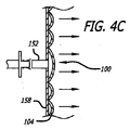
図4Cのように、患者服100の少なくとも一部が比較的通気性であれば、非通気性シート158は患者服100の外面104に患者服の通気性部分を覆って封止され得る。このような場合、吸気口152又は吸気口152及び153は、患者服100の外面104に取り付けられた非通気性シート158上に形成されるか取り付けられる。更に、患者服100の通気性部分は患者服100の内面106の一部を含むことから、対流保温器150は少なくとも部分的に内面106の残りの部分によって支持される。
As shown in FIG. 4C, if at least a portion of the
これらすべての場合において、対流保温器は、患者服が着用されるか、又はその内面106が患者を包囲するように、若しくは包囲するのでなければ内面106が患者に面するように配置された状態で、通気性シートが加温された空気を患者服100の内側に向けて放出するように、患者服上に支持される。
In all these cases, the convection incubator is either worn by the patient's clothes or arranged so that its
場合によっては、図5Aに示されるように吸気口152及び153は、対流保温器150の少なくとも一部を貫通する開口180からなる。好ましい実施形態では、孔180はほぼ円孔であり、厚紙又はプラスチックなどの、ある程度可撓性の材料からなる枠182によって囲まれている。孔180は、製造時に、この孔180が貫通することになる対流保温器の材料を除去することによって、完全に開いた状態で作製され得る。あるいは孔180は、はじめは製造時において対流保温器の材料中に任意パターンの切取り用ミシン目によって画され、その後、このミシン目パターンを通して空気ホースのノズルが押し込まれることによって完全に開くようにすることもできる。更に、図5Aの吸気口は、2つ以上の吸気口が対流保温器の一方又は両方の区分に設けられる構成におけるように、除去可能なプラグを備えるものとして設けられてもよい。このような吸気口の例は米国特許第7,578,837号に記載され、図示されている。他の場合には、図5Bに示すように吸気口152及び153は、対流保温器150を貫通して膨張式領域内に開口する、可撓性材料からなる筒又は管185を含む。このような吸気口の例は、公開公報第WO 2003/086500号に記載されるとともに、米国特許第5360439号に示されている。
In some cases, as shown in FIG. 5A, the
対流保温器の現時点で最良の構成方法によれば、個別膨張式の区分を備えた単一の膨張式対流保温器が、患者服とは別に製造され又は組み立てられた後、患者服の内面に縫合、接着、熱融着、溶接、又はこれらの任意の組合せにより付着される。対流保温器は、2つの材料シートを相互に熱融着することによって形成される。比較的通気性のよいシートは、ポリプロピレン層がその上に押出し成形される不織布材層からなる積層シートであり、非通気性のシートはポリプロピレンフィルムである。積層シートを通気性にするために、積層シートを貫通して開口が形成される。透過率はこの開口の寸法及び密度によって設定される。ポリプロピレンフィルム及びポリプロピレン層は、膨張式領域を形成するために周辺に沿って相互に封止されるとともに、周辺内側の不連続性のシール又は熱かしめ点で封止される。必要に応じてポリプロピレンフィルムとポリプロピレン層との間に別のシールが形成されることで、分離した区分及びその他の特徴形態が形成される。ポリプロピレンフィルム(これによって非通気性シートが構成される)は、接着、縫合、又は熱融着により患者服の内面に付着され、通気性シートの不織布材層が患者に面する。ポリプロピレンフィルムを患者服の内面上に配置するのは、膨張式対流保温器の嵩及び剛性を低減することで、保温装置を患者にとってより快適なものにするためである。 According to the current best method of construction of a convection incubator, after a single inflatable convection incubator with individual inflatable sections is manufactured or assembled separately from the patient garment, It is attached by stitching, gluing, heat sealing, welding, or any combination thereof. A convection warmer is formed by thermally fusing two material sheets together. The relatively air-permeable sheet is a laminated sheet made of a nonwoven material layer on which a polypropylene layer is extruded, and the non-air-permeable sheet is a polypropylene film. In order to make the laminated sheet breathable, an opening is formed through the laminated sheet. The transmittance is set by the size and density of this opening. The polypropylene film and the polypropylene layer are sealed together along the periphery to form an inflatable region and are sealed with a discontinuous seal or heat staking point inside the periphery. A separate seal is formed between the polypropylene film and the polypropylene layer as needed to form separate sections and other features. The polypropylene film (which constitutes a non-breathable sheet) is adhered to the inner surface of the patient's clothing by gluing, stitching, or heat fusion, and the non-woven material layer of the breathable sheet faces the patient. The reason why the polypropylene film is disposed on the inner surface of the patient's clothes is to make the heat retaining device more comfortable for the patient by reducing the bulk and rigidity of the inflatable convection warmer.
あるいは、通気性及び非通気性のシートはそれぞれ、ポリプロピレンを1面に押出し成形したコーティングを備えるスパンボンド不織布材層を含む。一方のシートに、必要な透過率に応じて開口が形成される。各シートの押出し成形コーティングを施した側が相互に面するように配置され、対流保温器の構成上の必要に応じ、例えば、熱により封止される。この構成では、対流保温器の外面は不織布材によって構成される。対流保温器の患者服内面に面する表面は不織布であり、患者が手をハンドスリット140に差し入れることで、手は柔軟な材料に心地よく触れることになる。 Alternatively, the breathable and non-breathable sheets each include a spunbond nonwoven material layer with a coating extruded on one side of polypropylene. An opening is formed in one sheet according to the required transmittance. The extrusion coated coatings of each sheet are arranged so that they face each other, and are sealed by heat, for example, as necessary in the configuration of the convection warmer. In this configuration, the outer surface of the convection warmer is made of a nonwoven material. The surface of the convection warmer that faces the inner surface of the patient's clothing is a non-woven fabric. When the patient inserts the hand into the hand slit 140, the hand can touch the soft material comfortably.
図3A及び3Bから見てとれるように、ポンチョ型構成を備える患者服は、患者服の1つ以上の要素の一方の側端から他方の側端までの測定値の幅と、任意の具体的な設計に必要とされる長さとを有する、患者服材料の矩形ブランクから作製できる。例えば、後パネル110又は中央パネル112の幅によってブランクの幅が設定され、下端120、124によって長さが設定され得る。同様にポンチョ型構成を備える患者服は、ブランクの幅に相当する標準幅の患者服材料ウェブを用いて、ウェブ系生産ラインで製造することができる。更に、患者服のための膨張式対流保温器がブランク幅より狭い幅を備えた、細長い、基本的に矩形の形状を有する場合には、基本的に矩形の対流保温器もまた、ウェブ系生産ラインで製造することが可能である。すなわち、ポンチョ型患者服の内面に支持された膨張式対流保温器によって少なくとも1つの患者保温モードを提供する患者保温装置のための患者服は、ウェブ系生産ラインで効率的かつ安価に製造され得る。生産ラインにおいて、患者服ブランクの幅に相当する標準幅の患者服材料ウェブが処理され、対流保温器ウェブへと結合される。
As can be seen from FIGS. 3A and 3B, a patient garment with a poncho-type configuration can have a range of measurements from one side edge to the other edge of one or more elements of the patient garment and any particular embodiment. Can be made from a rectangular blank of patient clothing material having the length required for a simple design. For example, the width of the blank can be set by the width of the
例えば、図3A及び3Bのポンチョ型構成を有する患者服は、図6のウェブ系生産システム200において、患者服ウェブ202を患者服材料ロール204から、ダーツ、ウェッジ、ハンドスリット、袖スリット及び/又は切取り用ミシン目、並びに締結用条片切取り用ミシン目のダイカットが行われる成形工程206を通して供給することによって、製造され得る。成形後、患者服ウェブ202は、1つ以上の付着具工程208を通して供給され、そこで患者服ウェブ202の両面にフックループ材料片が付与され、次いで結合工程210を通して供給され、ここで、対流保温器214を患者服ウェブ202の、患者服の内面に相当する面に結合することによって、複合ウェブ212が形成される。所望により、対流保温器ウェブ214を別個のウェブ系生産ラインで製造し、ロールにしてから結合工程210へと供給することも可能である。いずれの場合も、対流保温器ウェブ214は、非通気性材料のウェブ220を、非通気性材料のウェブ222がスパイクローラー224上を通ることで孔が形成されて通気性となる第2のウェブ222に結合することによって、製造される。ウェブ220及び222が結合工程226を通過し、そこで周辺シール、(頭部開口を含む)特定の特徴形態に応じたシール、及び非通気性材料ウェブ220と通気性材料ウェブ222との間の空気チャネル用かしめ点又はシールが形成されることによって、対流保温器ウェブ214が製造される。その後、対流保温器の付着した個別の患者服が、複合ウェブ212から切り出される。あるいは、複合ウェブ212をロールにし、別の場所に運んで患者保温装置の分離を行ってもよい。頭部開口は、患者服ウェブ202及び対流保温器ウェブ214を結合に先立って個別にダイカットすることにより形成することができる。しかしながら、頭部開口116、166(並びに袖部のためのスリット145及び/又は横方向切取り用ミシン目線146)を複合ウェブ212に、結合工程部の後で実行される単一工程でダイカットすることによって、裁断工程を1つ削減し、費用を低減することができる。単一工程ダイカットに、頭部開口シール164内への切取り用ミシン目パターンを、このパターン内側の複合ウェブ材料を除去することなく形成することを含めるようにすれば、費用は更に低減される。これに関し、パターン内部の余分な複合ウェブ材料の除去及び廃棄をユーザーが行うようにすることで、これに相当する製造工程が削減される。
For example, the patient apparel having the poncho-type configuration of FIGS. 3A and 3B may be used in the web-based
図7は、ポンチョ型患者服上に支持された膨張式対流保温器によって少なくとも1つの患者保温モードが提供される患者保温装置による、患者の上半身の保温を示す。好ましくは患者保温装置は、少なくとも保温治療に適するように構成されるが、これは必須ではない。例えば、患者保温装置は、図3A及び3Bの患者保温装置90のように構成でき、第2の区分172を上半身用保温毛布と同様に用いることによって、保温治療が提供される。図7は、好ましくは患者の腕のための十字形支持部を備えた手術台(図示せず)上で仰臥位にある患者の上方の位置から、患者服100の外面104に向かって見たものである。図7において、患者保温装置90は、袖を相互に結合する手段及び側端を相互に結合する手段を解放して配置できるように、調製されている。ポンチョ型構成に頭部開口116、166があることにより、患者保温装置90を除去することなく、患者服100をそれに付着した対流保温器150とともに患者の首の周りに回転させて、保温治療のために配置することが可能であり、また頭部開口が患者の首に係合することによって、患者保温装置90が適切な位置に保持される。この保温治療位置においては、前パネル108が患者の右腕の上に長手方向に配置され、後パネル110が患者の左腕の上に長手方向に配置される。患者保温装置がこの位置にある場合、第2の区分172は、通気性シートを患者側に向けて、患者の腕、肩、及び上胸部全体にわたって横方向に延在する。患者が仰臥位にある状態で、第2の区分を、保温治療用に調製された加温された空気の流れにより、吸気口153を介して膨らませる。第2の区分が膨らむと、加温された空気が通気性シートを貫通して患者上に放出される。ストラップ138を用いて、患者保温装置90を患者の腕の周りに隙間が開かないように保持し、かつ/又は手術台に固定することができる。図7に示すように、前パネル、後パネル、及び中央パネルの寸法は、患者の腕及び下腹部を覆う患者服領域に十分余裕のある長さを提供することで、対流保温器から放出される加温された空気を患者保温装置下に保持し、これによって所望の患者保温治療に寄与する。
FIG. 7 shows the warming of the patient's upper body with a patient warming device in which at least one patient warming mode is provided by an inflatable convection warmer supported on a poncho-type patient garment. Preferably, the patient warming device is configured to be suitable for at least warming therapy, but this is not essential. For example, the patient warming device can be configured like the
図8は、ポンチョ型の患者服の内面に支持された膨張式の対流保温器によって少なくとも1つの患者保温モードを提供する患者保温装置による、患者の全身又は下半身保温を示す。好ましくは患者保温装置は、保温治療に適するように構成されるが、これは必須ではない。例えば患者保温装置は、図3A及び3Bの患者保温装置90のように構成でき、第2の区分172を上全身又は下半身用保温毛布と同様に用いることによって、保温治療が提供される。図8は、手術台(図示せず)上で仰臥位にある患者の上方の位置から、患者服100の外面104に向かって見たものである。図8において患者保温装置90は、袖を相互に結合する手段及び側端を相互に結合する手段を解放し、かつ頭部開口116、166を患者の首から引き抜くことで装置を患者から除去することによって配置されるように、調製されている。いったん患者から除去された後で、患者保温装置90は、患者への全身又は下半身用保温治療のために患者上に配置される。このような保温治療位置では、後パネル110が患者上に長手方向に、患者の胸の上又は近くから下方に向けて少なくとも患者の下腹部及び脚部まで延在するように配置される。患者保温装置がこの位置にある場合、第2の区分172は、通気性シートを患者側に向けて、患者の胴体中央部、脚、及び足に沿って長手方向に延在する。患者が仰臥位にある状態で、第2の区分を、保温治療用に調製された加温された空気の流れにより、吸気口153を介して膨らませる。第2の区分が膨らむと、加温された空気が通気性シートを通して患者上に放出される。ストラップ138を用いて、患者保温装置90を患者の身体の周りに隙間が開かないように保持し、かつ/又は手術台に固定することができる。図8に示されるように、前、後、及び中央パネルの寸法は、患者の体側及び脚を覆う患者服領域に十分余裕のある長さを提供することで、対流保温器から放出される加温された空気を患者保温装置下に保持し、これによって所望の患者保温治療に寄与する。
FIG. 8 shows the patient's whole body or lower body warming with a patient warming device that provides at least one patient warming mode with an inflatable convection warmer supported on the inner surface of a poncho-type patient garment. Preferably, the patient warming device is configured to be suitable for warming therapy, but this is not essential. For example, the patient warming device can be configured like the
以上に図示し詳細に説明した、好ましい患者ポンチョ型患者服を備える患者保温装置構成は、本発明の目的を充分に達成する。しかしながら、説明した実施形態は単に、本発明によって広範に理解される対象を代表する例に過ぎない。したがって、当業者に明白であり得る他の実施形態も完全に本発明の範囲に包含される。ゆえに、本発明の範囲は、以下の特許請求の範囲以外によって制限されるものではなく、特許請求の範囲において単数で示される要素は、「ただ1つのみ」を意味するように意図されるのではなく、「少なくとも1つ」を意味するように意図されている。本発明は請求の範囲に包含されるべきものであるから、患者保温装置又は方法において解決されるべきあらゆる問題を本発明によって取り上げる必要はない。更に、本開示におけるいずれの要素、部品、又は方法上の工程も、それらの要素、部品、又は方法上の工程が「特許請求の範囲」において明示的に列挙されていると否とにかかわらず、公衆に捧げることを意図するものではない。詳細な説明に明記した定義に表されない限り、請求の範囲中の用語は、明細書及び出願経過書類に矛盾しない、普通かつ通常の意味を有するものとする。 The patient warming device configuration with the preferred patient poncho-type patient garment shown and described in detail above sufficiently accomplishes the objectives of the present invention. However, the described embodiments are merely examples that represent objects that are to be broadly understood by the present invention. Accordingly, other embodiments that may be apparent to those skilled in the art are also fully encompassed within the scope of the invention. Accordingly, the scope of the invention is not limited except as by the following claims, and elements recited in the singular are intended to mean "only one" in the claims. Rather, it is intended to mean “at least one”. Since the present invention is intended to be encompassed by the claims, it is not necessary for the present invention to address every problem to be solved in a patient warming device or method. Further, any element, part, or method step in the present disclosure, whether or not such element, part, or method step is explicitly recited in the Claims, It is not intended to be dedicated to the public. Unless expressed in the definitions set forth in the detailed description, the terms in the claims shall have their ordinary and ordinary meanings consistent with the specification and application history.
Claims (4)
前記患者服は、
内面(106)及び該内面とは反対側の外面(104)を有する単一の平坦な部材に展開可能なポンチョ型患者服であり、
中央パネル(112)と、
前記中央パネルの前端部から前方へ延出する前パネル(108)と、
前記中央パネルの後端部から後方へ延出する後パネル(110)と、
前記中央パネルの一方の側部から側方へ延出する第1の袖部(114)と、
前記中央パネルの他方の側部から、前記第1の袖部とは反対側へ延出する第2の袖部と、
前記第1の袖部と前記第2の側部との間に位置するように前記中央パネルに形成された頭部開口(30、116)と、を備え、
前記膨張式対流保温器は、前記内面(106)上に支持され、前記前パネル及び前記中央パネルに亘って少なくとも前記頭部開口まで延在し、
少なくとも1つの吸気口(27、152、153)が、前記膨張式対流保温器の非通気性の部分(158)を通って開口することを特徴とする、患者保温装置内の患者服。 A Rise Zhang convection incubator (150) by at least one patient insulation device patient kept mode is provided (20) in the patient's clothes (22,100),
The patient clothes are
A poncho-type patient garment deployable on a single flat member having an inner surface (106) and an outer surface (104) opposite the inner surface ;
A central panel (112) ;
A front panel (108) extending forward from the front end of the central panel;
A rear panel (110) extending rearward from the rear end of the central panel;
A first sleeve (114) extending laterally from one side of the central panel;
A second sleeve extending from the other side of the central panel to the opposite side of the first sleeve;
E Bei said central panel formed head opening (30,116), so as to be positioned between said first sleeve portion and said second side,
The inflatable convection warmer is supported on the inner surface (106) and extends over the front panel and the central panel to at least the head opening;
Patient clothing in a patient warming device, characterized in that at least one inlet (27, 152, 153) opens through the non-breathable part (158) of the inflatable convection warmer.
前記非通気性材料シートは、前記患者服の前記内面に取り付けられ、
前記少なくとも1つの吸気口は、前記非通気性材料シートにある、請求項1に記載の患者保温装置内の患者服。 The inflatable convection incubator has at least a non-breathable material sheet and a breathable material sheet sealed together by a peripheral seal,
The non-breathable material sheet is attached to the inner surface of the patient garment;
The patient clothing in a patient warming device according to claim 1, wherein the at least one inlet is in the non-breathable material sheet.
前記少なくとも1つの吸気口は、第1の区分内への少なくとも1つの吸気口、および、第2の区分内への少なくとも1つの吸気口を含む、請求項2に記載の患者保温装置内の患者服。 The inflatable convection incubator has individual inflatable sections,
The patient in a patient warming device according to claim 2, wherein the at least one inlet includes at least one inlet into the first section and at least one inlet into the second section. clothes.
前記非通気性材料シートは、前記内面に取り付けられ、
前記少なくとも1つの吸気口は、剛性材料からなる枠を含み、該剛性材料からなる枠は、前記非通気性材料シートの開口の周りで該非通気性材料シートに取り付けられる、請求項1に記載の患者保温装置内の患者服。 The inflatable convection incubator has a non-breathable material sheet and a breathable material sheet sealed to the non-breathable material sheet along a common periphery,
The non-breathable material sheet is attached to the inner surface;
The said at least one air inlet includes a frame made of rigid material, and the frame made of rigid material is attached to the non-breathable material sheet around an opening of the non-breathable material sheet. Patient clothing in patient warmer.
Applications Claiming Priority (3)
| Application Number | Priority Date | Filing Date | Title |
|---|---|---|---|
| US12/653,825 | 2009-12-21 | ||
| US12/653,825 US8192475B2 (en) | 2002-04-10 | 2009-12-21 | Warming device constructions with a poncho-type patient gown |
| PCT/US2010/003051 WO2011084123A1 (en) | 2009-12-21 | 2010-11-24 | Warming device constructions with a poncho-type patient gown |
Publications (3)
| Publication Number | Publication Date |
|---|---|
| JP2013514857A JP2013514857A (en) | 2013-05-02 |
| JP2013514857A5 JP2013514857A5 (en) | 2013-11-28 |
| JP5823980B2 true JP5823980B2 (en) | 2015-11-25 |
Family
ID=43608610
Family Applications (1)
| Application Number | Title | Priority Date | Filing Date |
|---|---|---|---|
| JP2012545924A Active JP5823980B2 (en) | 2009-12-21 | 2010-11-24 | Composition of heat insulation device with poncho type patient clothes |
Country Status (6)
| Country | Link |
|---|---|
| US (1) | US8192475B2 (en) |
| EP (1) | EP2515807A1 (en) |
| JP (1) | JP5823980B2 (en) |
| CN (1) | CN102770096A (en) |
| BR (1) | BR112012015299A2 (en) |
| WO (1) | WO2011084123A1 (en) |
Families Citing this family (11)
| Publication number | Priority date | Publication date | Assignee | Title |
|---|---|---|---|---|
| US8172890B2 (en) * | 2009-02-18 | 2012-05-08 | Smiths Medical Asd, Inc. | Combination underbody and overbody blanket |
| US9956112B2 (en) * | 2010-08-30 | 2018-05-01 | The Surgical Company International B.V. | Prewarming gown |
| JP6289499B2 (en) | 2012-12-13 | 2018-03-07 | スリーエム イノベイティブ プロパティズ カンパニー | Patient warming gown with ambient warming |
| US9394637B2 (en) | 2012-12-13 | 2016-07-19 | Jacob Holm & Sons Ag | Method for production of a hydroentangled airlaid web and products obtained therefrom |
| WO2015030248A1 (en) * | 2013-09-02 | 2015-03-05 | Ikk株式会社 | Production method for composite fabric equipped with fluid circuit, and composite fabric equipped with fluid circuit |
| EP2893910B1 (en) * | 2014-01-10 | 2020-02-26 | The Surgical Company International B.V. | Forced air warming blanket |
| US11395759B2 (en) * | 2014-08-18 | 2022-07-26 | Medline Industries, Lp | Method and apparatus pertaining to securement of a personal patient warming apparatus |
| US10441006B2 (en) | 2015-12-07 | 2019-10-15 | Medline Industries, Inc. | Patient-warming gown |
| AU2018263280A1 (en) * | 2017-05-02 | 2019-11-14 | Care Essentials Pty Ltd | A blanket for venipuncture |
| US11103017B2 (en) * | 2017-09-01 | 2021-08-31 | Dupont Safety & Construction, Inc. | Protective garment with harness access |
| EP4188291A1 (en) * | 2020-08-03 | 2023-06-07 | 3M Innovative Properties Company | Patient warming systems and corresponding methods |
Family Cites Families (91)
| Publication number | Priority date | Publication date | Assignee | Title |
|---|---|---|---|---|
| FR821150A (en) | 1936-05-14 | 1937-11-27 | Apparatus for the application of thermotherapy | |
| GB475811A (en) | 1936-05-25 | 1937-11-25 | Benjamin Hill | Heating or cooling garment |
| US2512559A (en) | 1945-01-18 | 1950-06-20 | Alfred L W Williams | Comfort unit |
| US2573414A (en) | 1947-03-05 | 1951-10-30 | Karl L Dunn | Hot work garment |
| US2826758A (en) | 1955-12-15 | 1958-03-18 | Kahn Alexander | Ventilated clothing and apparatus |
| US3468299A (en) | 1967-12-20 | 1969-09-23 | Carl D Amato | Air-conditioned garment |
| US3610323A (en) | 1969-10-20 | 1971-10-05 | Dan E Troyer | Cool coat |
| US3757366A (en) | 1971-08-18 | 1973-09-11 | W Sacher | Cushion for preventing and alleviating bedsores |
| GB1462033A (en) | 1973-01-19 | 1977-01-19 | Secr Defence | Apparatus for 0ntrolling the temperature of the human body |
| US3855635A (en) | 1973-05-17 | 1974-12-24 | C Ramirez | Two piece hospital gown |
| US3911499A (en) | 1974-06-06 | 1975-10-14 | Kimberly Clark Co | Disposable medical gown |
| US4055173A (en) | 1975-04-21 | 1977-10-25 | Knab James V | Surgical masking and ventilating system |
| US3950789A (en) | 1975-07-22 | 1976-04-20 | Kansas State University Research Foundation | Dry ice cooling jacket |
| US4146933A (en) | 1976-07-19 | 1979-04-03 | Barry R. Jenkins | Conditioned-air suit and system |
| US4369528A (en) | 1981-02-23 | 1983-01-25 | Alba-Waldensian, Inc. | Garment for maintaining body temperature and method of making same |
| US4494248A (en) | 1982-07-22 | 1985-01-22 | Holder Percy E A | Fabu patient gown |
| US4524463A (en) | 1982-09-13 | 1985-06-25 | Ogden Danny W | Wrap around garment |
| GB8333836D0 (en) | 1983-12-20 | 1984-02-01 | Howorth Air Eng Ltd | Body exhaust gown |
| US4787101A (en) | 1984-08-15 | 1988-11-29 | Alixandra Feinberg | Garment for convalescents |
| US4558468A (en) | 1984-10-05 | 1985-12-17 | The Kendall Company | Surgical gown having one-piece-belt system |
| US4587671A (en) | 1985-02-19 | 1986-05-13 | American Hospital Supply Corporation | Open, wraparound, sleeved garment |
| US4578825A (en) | 1985-07-22 | 1986-04-01 | Vote Marjean D | Smock or gown |
| US4653120A (en) | 1985-11-22 | 1987-03-31 | Sallie Leaf | Hospital-type gown with front and rear openings |
| US4696066A (en) | 1986-09-15 | 1987-09-29 | Ball Joyce A | Heated coat liner |
| US4718124A (en) | 1987-01-13 | 1988-01-12 | Sawicki Marsha M | Patient gown |
| US5405371A (en) | 1987-10-05 | 1995-04-11 | Augustine Medical, Inc. | Thermal blanket |
| US6551347B1 (en) | 1988-09-28 | 2003-04-22 | Life Enhancement Technologies, Inc. | Cooling/heating system |
| US4914752A (en) | 1989-01-27 | 1990-04-10 | Abandaco, Inc. | Temperature-regulated garment utilizing a vortex tube |
| US5025355A (en) | 1989-11-03 | 1991-06-18 | Harwood Ronald P | Combination lighting fixture and graphic display means |
| US4964282A (en) | 1989-12-07 | 1990-10-23 | Wagner Christopher S | Detachable bulletproof vest air conditioning apparatus |
| US5044214A (en) | 1989-12-11 | 1991-09-03 | Barber Jr John S | Toroidal transmission with split torque and equalization planetary drive |
| US5043968A (en) | 1990-04-24 | 1991-08-27 | Showa Electric Co., Ltd. | Apparatus for cleaning the pick up lens of a compact disc player |
| US5062424A (en) | 1991-01-24 | 1991-11-05 | The University Of North Carolina At Chapel Hill | Portable apparatus for rapid reduction of elevated body core temperature |
| US5190031A (en) | 1991-03-11 | 1993-03-02 | Raul Guibert | Universal thermotherapy applicator |
| US5384924A (en) | 1992-08-03 | 1995-01-31 | Mallinckrodt Medical, Inc. | Warming blanket having multiple inlets |
| US5255390A (en) | 1992-12-03 | 1993-10-26 | Chem-Tex Corporation | Gas ventilated garment having a low gas consumption valving configuration |
| US5740405A (en) | 1992-12-17 | 1998-04-14 | Microsoft Corporation | Method and system for providing data compatibility between different versions of a software program |
| US5367710A (en) | 1993-01-12 | 1994-11-29 | Karmin; James L. | Medical gown for preserving privacy |
| US5304213A (en) | 1993-06-14 | 1994-04-19 | Cincinnati Sub-Zero Products, Inc. | Hyper-hypothermia blanket with filtration properties |
| US6004644A (en) | 1994-07-26 | 1999-12-21 | Ngk Insulators, Ltd. | Zirconia diaphragm structure and piezoelectric/electrostrictive film element having the zirconia diaphragm structure |
| US5411541A (en) | 1993-08-05 | 1995-05-02 | Oansh Designs Ltd. | Portable fluid therapy device |
| EP0741553B1 (en) | 1994-01-26 | 2004-11-24 | Mallinckrodt Inc. | Warming blanket for pediatric use |
| US5443488A (en) | 1994-08-15 | 1995-08-22 | Progressive Dynamics, Inc. | Thermal blanket with surgical access |
| US5545194A (en) | 1994-09-30 | 1996-08-13 | Augustine Medical, Inc. | Convertible thermal blanket |
| US5575006A (en) | 1994-12-05 | 1996-11-19 | Wolfe; Dorothy T. | Hospital privacy garment |
| JP3191583B2 (en) | 1994-12-12 | 2001-07-23 | ソニー株式会社 | Information decryption device |
| US5572742A (en) | 1995-04-06 | 1996-11-12 | Vansur Investments & Asociados | Garment for the disabled |
| US5611087A (en) | 1995-08-31 | 1997-03-18 | Adkins; Lola | Separable garment |
| DE69629577T2 (en) | 1995-10-18 | 2004-07-15 | Mallinckrodt Medical, Inc. | INFLATABLE BLANKET WITH SELECTIVE AIRFLOW PATTERNS |
| US5749109A (en) | 1995-10-18 | 1998-05-12 | Mallinckrodt Medical, Inc. | Inflatable blanket having selective air flow patterns |
| US5697963A (en) | 1995-12-20 | 1997-12-16 | Augustine Medical, Inc. | Thermal blanket for a patient sitting in a chair |
| US5768707A (en) * | 1996-03-20 | 1998-06-23 | Bonnie Lederer | Examination gown |
| US5997572A (en) | 1996-03-29 | 1999-12-07 | Augustine Medical, Inc. | Inlet port plug for inflatable thermal blankets |
| US5891187A (en) | 1996-05-09 | 1999-04-06 | Winthrop; Neil | Temperature control pad for use during medical and surgical procedures |
| US5785716A (en) | 1996-05-09 | 1998-07-28 | Bayron; Harry | Temperature control pad for use during medical and surgical procedures |
| US5739605A (en) | 1996-12-23 | 1998-04-14 | Electroid Co.,A Division Of Valcor Engineering Corp. | Bi-stable clutch |
| US6109338A (en) | 1997-05-01 | 2000-08-29 | Oceaneering International, Inc. | Article comprising a garment or other textile structure for use in controlling body temperature |
| US5946722A (en) | 1997-05-28 | 1999-09-07 | Trautmann; Charlotte B. | Patient privacy gown |
| US5941907A (en) | 1997-06-02 | 1999-08-24 | Augustine Medical, Inc. | Surgical barrier device incorporating an inflatable thermal blanket with a surgical drape to provide thermal control and surgical access |
| AU752912B2 (en) | 1997-12-08 | 2002-10-03 | Molnlycke Health Care Ab | Medical linen with regionally imprinted performance areas |
| US6049907A (en) | 1998-01-26 | 2000-04-18 | Allegiance Corporation | Gown tie |
| US5970519A (en) | 1998-02-20 | 1999-10-26 | Weber; Stanley | Air cooling garment for medical personnel |
| US6154883A (en) | 1998-07-09 | 2000-12-05 | Thy Enterprises, Inc. | Garment for wear following thoracic surgery |
| US6102936A (en) | 1998-07-21 | 2000-08-15 | Augustine Medical, Inc. | Inflatable thermal pad with drainage |
| IL129465A (en) | 1999-04-15 | 2005-03-20 | M T R E Advanced Technology Lt | Heat exchanger garment |
| US6799332B2 (en) | 1999-11-01 | 2004-10-05 | Richard L. Hatton | Two-piece patient examination garment |
| US6216270B1 (en) | 2000-03-10 | 2001-04-17 | Gary J. Moquin | Patient garment having enhanced accessibility |
| JP3578697B2 (en) | 2000-04-27 | 2004-10-20 | ユニ・チャーム株式会社 | Disposable jacket |
| US6571574B1 (en) | 2000-06-21 | 2003-06-03 | Ralf W. Blackstone | Air cooling device |
| JP2002220712A (en) | 2001-01-19 | 2002-08-09 | Uni Charm Corp | Disposable outerwear for medical operation |
| US6484321B1 (en) | 2001-05-04 | 2002-11-26 | Ronnye B. Shamam | Multi-purpose patient hospital gown |
| US6596019B2 (en) | 2001-08-30 | 2003-07-22 | Nike International Ltd. | Apparel ventilation system |
| US20030126668A1 (en) | 2002-01-10 | 2003-07-10 | Scroggins Georgia W. | Hospital dressing gown construction |
| US6792622B2 (en) | 2002-03-14 | 2004-09-21 | Stephen K. Graves | Patient garments |
| JP4828797B2 (en) | 2002-04-10 | 2011-11-30 | アリザント ヘルスケア インク. | Instruments and systems that keep patients comfortable |
| US6820622B1 (en) | 2002-06-07 | 2004-11-23 | Leonides Y. Teves | Thermal surgical drape |
| AU2003238907A1 (en) | 2002-06-14 | 2003-12-31 | Ralf W. Blackstone | An air cooling device |
| SE525415C2 (en) | 2002-07-03 | 2005-02-15 | Moelnlycke Health Care Ab | Heat-emitting patient costume |
| US6647552B1 (en) | 2003-02-05 | 2003-11-18 | Guided Inspiration, Inc. | Medical dignity garment |
| US6694522B1 (en) | 2003-04-08 | 2004-02-24 | Jay G. Neal | Universal hospital gown |
| US20050015127A1 (en) | 2003-04-10 | 2005-01-20 | Bieberich Mark T. | Perioperative warming device |
| US6876884B2 (en) | 2003-04-10 | 2005-04-05 | Arizant Healthcare Inc. | Forced air warming unit |
| US7226454B2 (en) | 2004-12-07 | 2007-06-05 | Arizant Healthcare Inc. | Warming device with varied permeability |
| US7846192B2 (en) | 2004-12-07 | 2010-12-07 | Arizant Healthcare Inc. | Warming device |
| US7364584B2 (en) | 2004-12-07 | 2008-04-29 | Arizant Healthcare Inc. | Warming device |
| US7520889B2 (en) | 2005-02-11 | 2009-04-21 | Arizant Healthcare Inc. | Thermal blanket for warming the limbs |
| US8454672B2 (en) | 2005-02-11 | 2013-06-04 | Arizant Healthcare Inc. | Warming device for perioperative use |
| US7470280B2 (en) | 2005-02-11 | 2008-12-30 | Arizant Healthcare Inc. | Clinical garment for comfort warming and prewarming |
| US7871429B2 (en) | 2005-10-20 | 2011-01-18 | Arizant Healthcare Inc. | Multifunction warming device with provision for being secured |
| US8097031B2 (en) | 2005-10-20 | 2012-01-17 | Arizant Healthcare Inc. | Warming device with provisions for deploying elements of an upper body convective apparatus and for deploying the lower portion of the warming device |
| US7862599B2 (en) | 2007-01-23 | 2011-01-04 | Arizant Healthcare Inc. | Convective warming device with a drape |
-
2009
- 2009-12-21 US US12/653,825 patent/US8192475B2/en not_active Expired - Fee Related
-
2010
- 2010-11-24 WO PCT/US2010/003051 patent/WO2011084123A1/en active Application Filing
- 2010-11-24 BR BR112012015299A patent/BR112012015299A2/en not_active IP Right Cessation
- 2010-11-24 EP EP10795099A patent/EP2515807A1/en not_active Withdrawn
- 2010-11-24 JP JP2012545924A patent/JP5823980B2/en active Active
- 2010-11-24 CN CN2010800586978A patent/CN102770096A/en active Pending
Also Published As
| Publication number | Publication date |
|---|---|
| CN102770096A (en) | 2012-11-07 |
| JP2013514857A (en) | 2013-05-02 |
| EP2515807A1 (en) | 2012-10-31 |
| US8192475B2 (en) | 2012-06-05 |
| US20100179624A1 (en) | 2010-07-15 |
| WO2011084123A1 (en) | 2011-07-14 |
| BR112012015299A2 (en) | 2017-04-25 |
Similar Documents
| Publication | Publication Date | Title |
|---|---|---|
| JP5823980B2 (en) | Composition of heat insulation device with poncho type patient clothes | |
| CA2658380C (en) | Warming device | |
| US8043350B2 (en) | Warming device | |
| AU2005314264B2 (en) | Warming device with varied permeability | |
| US7276076B2 (en) | Perioperative warming device | |
| AU2011298448B2 (en) | Prewarming gown |
Legal Events
| Date | Code | Title | Description |
|---|---|---|---|
| A521 | Request for written amendment filed |
Free format text: JAPANESE INTERMEDIATE CODE: A523 Effective date: 20131009 |
|
| A621 | Written request for application examination |
Free format text: JAPANESE INTERMEDIATE CODE: A621 Effective date: 20131009 |
|
| A711 | Notification of change in applicant |
Free format text: JAPANESE INTERMEDIATE CODE: A711 Effective date: 20140131 |
|
| RD02 | Notification of acceptance of power of attorney |
Free format text: JAPANESE INTERMEDIATE CODE: A7422 Effective date: 20140207 |
|
| RD03 | Notification of appointment of power of attorney |
Free format text: JAPANESE INTERMEDIATE CODE: A7423 Effective date: 20140207 |
|
| RD04 | Notification of resignation of power of attorney |
Free format text: JAPANESE INTERMEDIATE CODE: A7424 Effective date: 20140213 |
|
| A521 | Request for written amendment filed |
Free format text: JAPANESE INTERMEDIATE CODE: A821 Effective date: 20140213 |
|
| A131 | Notification of reasons for refusal |
Free format text: JAPANESE INTERMEDIATE CODE: A131 Effective date: 20140909 |
|
| A977 | Report on retrieval |
Free format text: JAPANESE INTERMEDIATE CODE: A971007 Effective date: 20140912 |
|
| A601 | Written request for extension of time |
Free format text: JAPANESE INTERMEDIATE CODE: A601 Effective date: 20141208 |
|
| A602 | Written permission of extension of time |
Free format text: JAPANESE INTERMEDIATE CODE: A602 Effective date: 20141215 |
|
| A521 | Request for written amendment filed |
Free format text: JAPANESE INTERMEDIATE CODE: A523 Effective date: 20150309 |
|
| TRDD | Decision of grant or rejection written | ||
| A01 | Written decision to grant a patent or to grant a registration (utility model) |
Free format text: JAPANESE INTERMEDIATE CODE: A01 Effective date: 20150908 |
|
| A61 | First payment of annual fees (during grant procedure) |
Free format text: JAPANESE INTERMEDIATE CODE: A61 Effective date: 20151008 |
|
| R150 | Certificate of patent or registration of utility model |
Ref document number: 5823980 Country of ref document: JP Free format text: JAPANESE INTERMEDIATE CODE: R150 |
|
| R250 | Receipt of annual fees |
Free format text: JAPANESE INTERMEDIATE CODE: R250 |
|
| R250 | Receipt of annual fees |
Free format text: JAPANESE INTERMEDIATE CODE: R250 |
|
| R250 | Receipt of annual fees |
Free format text: JAPANESE INTERMEDIATE CODE: R250 |
|
| R250 | Receipt of annual fees |
Free format text: JAPANESE INTERMEDIATE CODE: R250 |
|
| R250 | Receipt of annual fees |
Free format text: JAPANESE INTERMEDIATE CODE: R250 |
|
| R250 | Receipt of annual fees |
Free format text: JAPANESE INTERMEDIATE CODE: R250 |
|
| S111 | Request for change of ownership or part of ownership |
Free format text: JAPANESE INTERMEDIATE CODE: R313111 |