JP5814869B2 - Game machine - Google Patents

Game machine Download PDF

Info

Publication number
JP5814869B2
JP5814869B2 JP2012150677A JP2012150677A JP5814869B2 JP 5814869 B2 JP5814869 B2 JP 5814869B2 JP 2012150677 A JP2012150677 A JP 2012150677A JP 2012150677 A JP2012150677 A JP 2012150677A JP 5814869 B2 JP5814869 B2 JP 5814869B2
Authority
JP
Japan
Prior art keywords
winning
switch
output
game
value
Prior art date
Legal status (The legal status is an assumption and is not a legal conclusion. Google has not performed a legal analysis and makes no representation as to the accuracy of the status listed.)
Active
Application number
JP2012150677A
Other languages
Japanese (ja)
Other versions
JP2014012082A5 (en
JP2014012082A (en
Inventor
小倉 敏男
敏男 小倉
Current Assignee (The listed assignees may be inaccurate. Google has not performed a legal analysis and makes no representation or warranty as to the accuracy of the list.)
Sankyo Co Ltd
Original Assignee
Sankyo Co Ltd
Priority date (The priority date is an assumption and is not a legal conclusion. Google has not performed a legal analysis and makes no representation as to the accuracy of the date listed.)
Filing date
Publication date
Application filed by Sankyo Co Ltd filed Critical Sankyo Co Ltd
Priority to JP2012150677A priority Critical patent/JP5814869B2/en
Publication of JP2014012082A publication Critical patent/JP2014012082A/en
Publication of JP2014012082A5 publication Critical patent/JP2014012082A5/ja
Application granted granted Critical
Publication of JP5814869B2 publication Critical patent/JP5814869B2/en
Active legal-status Critical Current
Anticipated expiration legal-status Critical

Links

Images

Description

本発明は、各々を識別可能な複数種類の識別情報の可変表示を行ない、表示結果としてあらかじめ定められた特定表示結果が導出表示されたときに遊技者にとって有利な特定遊技状態に制御し、遊技媒体の入賞によって遊技価値を付与可能な入賞領域を有するパチンコ遊技機等の遊技機に関する。 The present invention, respectively performs the variable display of identifiable multiple kinds of identification information, and controls the advantageous specific game state for the player when Viewing resulting predetermined specific display results derived displayed, The present invention relates to a gaming machine such as a pachinko gaming machine having a winning area to which a gaming value can be given by winning a gaming medium .

遊技機として、遊技媒体である遊技球を発射装置によって遊技領域に発射し、遊技領域に設けられている入賞口などの入賞領域に遊技球が入賞すると、所定個の賞球が遊技者に払い出されるものがある。さらに、識別情報を可変表示(「変動」ともいう。)可能な可変表示装置が設けられ、可変表示装置において識別情報の可変表示の表示結果が特定表示結果となった場合に、遊技状態(遊技機の状態。よって、具体的には、遊技機が制御されている状態。)を、所定の遊技価値を遊技者に与えるように構成されたものがある。   As a gaming machine, a game ball, which is a game medium, is launched into a game area by a launching device, and when a game ball wins a prize area such as a prize opening provided in the game area, a predetermined number of prize balls are paid out to the player. There is something to be done. Further, a variable display device capable of variably displaying the identification information (also referred to as “fluctuation”) is provided, and when the display result of the variable display of the identification information becomes a specific display result in the variable display device, the game state (game There is a machine configured to give a predetermined game value to a player (specifically, a state in which a gaming machine is controlled).

なお、遊技価値とは、遊技機の遊技領域に設けられた可変入賞球装置の状態が打球が入賞しやすい遊技者にとって有利な状態になることや、遊技者にとって有利な状態になるための権利を発生させたりすることや、賞球払出の条件が成立しやすくなる状態になることである。   The game value is the right that the state of the variable winning ball apparatus provided in the gaming area of the gaming machine becomes advantageous for a player who is easy to win, and the right for becoming advantageous for a player. In other words, or a condition for winning a prize ball is easily established.

パチンコ遊技機では、始動入賞口に遊技球が入賞したことに基づいて可変表示装置において開始される特別図柄(識別情報)の可変表示の表示結果として、あらかじめ定められた特定の表示態様が導出表示された場合に、「大当り」が発生する。なお、導出表示とは、図柄(最終停止図柄)を最終的に停止表示させることである。大当りが発生すると、たとえば、大入賞口が所定回数開放して打球が入賞しやすい大当り遊技状態に移行する。そして、各開放期間において、所定個(たとえば、10個)の大入賞口への入賞があると大入賞口は閉成する。そして、大入賞口の開放回数は、所定回数(たとえば、15ラウンド)に固定されている。なお、各開放について開放時間(たとえば、29秒)が決められ、入賞数が所定個に達しなくても開放時間が経過すると大入賞口は閉成する。以下、各々の大入賞口の開放期間をラウンドということがある。また、ラウンドにおける遊技をラウンド遊技ということがある。   In a pachinko machine, a specific display mode determined in advance is derived and displayed as a display result of variable display of a special symbol (identification information) that is started in the variable display device based on the winning of a game ball at the start winning opening. If this happens, a “big hit” will occur. The derived display is to finally stop and display a symbol (final stop symbol). When the big hit occurs, for example, the big winning opening is opened a predetermined number of times, and the game shifts to a big hit gaming state where the hit ball is easy to win. And in each open period, if there is a prize for a predetermined number (for example, 10) of big prize openings, the big prize opening is closed. And the number of times the special winning opening is opened is fixed to a predetermined number (for example, 15 rounds). An opening time (for example, 29 seconds) is determined for each opening, and even if the number of winnings does not reach a predetermined number, the winning opening is closed when the opening time elapses. Hereinafter, the opening period of each special winning opening may be referred to as a round. A game in a round may be referred to as a round game.

また、可変表示装置において、最終停止図柄(たとえば、左中右図柄のうち中図柄)となる図柄以外の図柄が、所定時間継続して、特定の表示結果と一致している状態で停止、揺動、拡大縮小もしくは変形している状態、または、複数の図柄が同一図柄で同期して変動したり、表示図柄の位置が入れ替わっていたりして、最終結果が表示される前で大当り発生の可能性が継続している状態(以下、これらの状態をリーチ状態という。)において行なわれる演出をリーチ演出という。また、リーチ状態やその様子をリーチ態様という。さらに、リーチ演出を含む可変表示をリーチ可変表示という。そして、可変表示装置に変動表示される図柄の表示結果が特定の表示結果でない場合には「はずれ」となり、変動表示状態は終了する。遊技者は、大当りをいかにして発生させるかを楽しみつつ遊技を行なう。   In addition, in the variable display device, the symbols other than the symbol that becomes the final stop symbol (for example, the middle symbol in the left middle right symbol) are stopped and shaken in a state in which the symbol continues for a predetermined time and matches the specific display result. It can be a big hit before the final result is displayed because it is moving, scaling, or deforming, or multiple symbols change synchronously with the same symbol, or the position of the displayed symbol is switched. An effect performed in a state where the sex is continued (hereinafter, these states are referred to as a reach state) is referred to as a reach effect. Further, the reach state and its state are referred to as a reach mode. Furthermore, variable display including reach production is called reach variable display. Then, when the display result of the symbol variably displayed on the variable display device is not a specific display result, it becomes “out of” and the variability display state ends. The player plays the game while enjoying how to generate the big hit.

そのような遊技機において、可動部材を用いた遊技を実行可能に構成されたものがある。たとえば、特許文献1には、可動部材が設けられた遊技機において、遊技機への電力供給が開始されたときに初期化処理が実行(RAMクリア)されると、可動部材を初期動作させて可動部材の原点位置を検出するように構成することが記載されている。   Some of these gaming machines are configured to be able to execute a game using a movable member. For example, in Patent Document 1, in a gaming machine provided with a movable member, when initialization processing is executed (RAM clear) when power supply to the gaming machine is started, the movable member is initialized. It is described that it is configured to detect the origin position of the movable member.

特開2010−142514号公報(段落0127−0128、段落 0134−0141、図15)JP 2010-142514 A (paragraph 0127-0128, paragraph 0134-0141, FIG. 15)

しかし、一般に、遊技機への電力供給が開始されたときに初期化処理が実行されると、初期化報知を実行することが行なわれている。すると、特許文献1に記載された遊技機のように可動部材の初期動作を実行するように構成すると、初期化処理が実行されたときに初期化報知と可動部材の初期動作とが重複したタイミングで実行されることになり、初期化報知と可動部材の初期動作とにかかる電力消費が集中してしまうという問題が生じる。   However, generally, when an initialization process is executed when power supply to a gaming machine is started, an initialization notification is executed. Then, when it is configured to execute the initial operation of the movable member as in the gaming machine described in Patent Document 1, when the initialization process is executed, the initialization notification and the initial operation of the movable member overlap. This causes a problem that power consumption for initialization notification and initial operation of the movable member is concentrated.

そこで、本発明は、初期化処理が実行されたときに初期化報知と可動部材の初期動作とにかかる電力消費を分散することができる遊技機を提供することを目的とする。   Therefore, an object of the present invention is to provide a gaming machine that can disperse the power consumption required for the initialization notification and the initial operation of the movable member when the initialization process is executed.

(手段1)本発明による遊技機は、各々を識別可能な複数種類の識別情報の可変表示を行ない、表示結果としてあらかじめ定められた特定表示結果が導出表示されたときに遊技者にとって有利な特定遊技状態に制御し、遊技媒体の入賞によって遊技価値を付与可能な入賞領域を有する遊技機であって、前記入賞領域に入賞した遊技媒体を検出可能な入賞検出部と、前記入賞領域に入賞した後に前記入賞検出部を通過した遊技媒体を検出可能な入賞確認部と、動作を行なう可動部材(たとえば、第2の実施の形態における可動部材78や演出羽根役物79a,79bなどの役物)と、遊技機への電力供給が停止しても所定期間記憶内容を保持可能であり、制御を行なう際に発生する変動データを記憶する変動データ記憶手段(たとえば、バックアップRAMとしてのRAM55)と、遊技機への電力供給が開始されたときに、所定条件の成立(たとえば、クリアスイッチのオン)に基づいて変動データ記憶手段の記憶内容を初期化する初期化処理を実行する初期化手段(たとえば、遊技制御用マイクロコンピュータ560におけるS10を実行する部分)と、初期化手段によって初期化処理が実行されたことに基づいて、初期化報知を実行する初期化報知手段(たとえば、第2の実施の形態において、演出制御用マイクロコンピュータ100におけるS3101〜S3111を実行する部分)と、遊技機への電力供給が開始されたことに基づいて、可動部材の初期動作を実行する初期動作実行手段(たとえば、第2の実施の形態において、演出制御用マイクロコンピュータ100におけるS708を実行する部分)と、異常(図47参照)が発生したことを判定する異常判定手段(遊技制御用マイクロコンピュータ560、図14のS23〜S27、S42、図27)と、異常判定手段が異常発生と判定したことに基づいて異常報知を実行する異常報知手段(演出制御用マイクロコンピュータ100、スピーカ27、各種ランプ、演出表示装置9)と、異常報知に関する条件(同時検出のときの優先順、報知態様、開始・解除条件)を異常判定時の状態(遊技状態、異常検出頻度、検出回数)に応じて変更する変更手段(演出制御用マイクロコンピュータ100、図48(a)、図56〜図59)と、前記入賞検出部で検出された遊技媒体の数と前記入賞確認部で検出された遊技媒体の数との差分が所定数以上となる差分異常が発生したことに基づいて、異常情報を外部出力する外部出力手段とを備え、初期動作実行手段は、初期化報知手段による初期化報知の実行を終了した後に、可動部材の初期動作を実行し(たとえば、第2の実施の形態において、演出制御用マイクロコンピュータ100は、S3502でYと判定したことを条件にS3503以降の処理に移行して役物の初期動作を実行する)、前記可動部材の初期動作を開始するにあたって前記識別情報の可変表示が実行されているときには、当該識別情報の可変表示とともに前記可動部材の初期動作を実行し、前記外部出力手段は、前記異常情報を外部出力しているときに前記遊技機への電力供給が停止し電力供給が再開され、前記初期化手段によって前記初期化処理が実行された場合には特定期間が経過するまで前記異常情報を外部出力し、前記初期化手段によって前記初期化処理が実行されなかった場合には少なくとも電力供給が停止されるまで前記異常情報を外部出力する。そのような構成により、初期化処理が実行されたときに初期化報知と可動部材の初期動作とにかかる電力消費を分散することができる。また、異常発生と判定されたときの異常報知に関する条件が異常判定時の状態に応じて変更されるため、異常発生時の状態に応じた適切な異常報知を行なうことができる (Means 1) The gaming machine according to the present invention performs variable display of a plurality of types of identification information that can be distinguished from each other, and is advantageous for the player when a predetermined specific display result is derived and displayed as a display result. A gaming machine that has a winning area that is controlled to a gaming state and can be given game value by winning a gaming medium, and that has won a winning detection section capable of detecting a gaming medium that has won the winning area, and has won the winning area A winning confirmation unit that can detect a game medium that has passed through the winning detection unit later, and a movable member that performs an operation (for example, a movable member 78 and effect blades 79a and 79b in the second embodiment) The stored data can be retained for a predetermined period even when the power supply to the gaming machine is stopped, and the fluctuation data storage means for storing the fluctuation data generated when the control is performed (for example, the back RAM 55), and initialization to initialize the stored contents of the fluctuation data storage means based on establishment of a predetermined condition (for example, clear switch ON) when power supply to the gaming machine is started Initialization notification for executing initialization notification based on the initialization means for executing the processing (for example, the part for executing S10 in the game control microcomputer 560) and the initialization processing being executed by the initialization means Based on the means (for example, the part for executing S3101 to S3111 in the production control microcomputer 100 in the second embodiment) and the start of power supply to the gaming machine, the initial operation of the movable member is performed. Initial operation execution means to be executed (for example, in the production control microcomputer 100 in the second embodiment) Part for executing S708), abnormality determination means for determining that an abnormality (see FIG. 47) has occurred (game control microcomputer 560, S23 to S27 in FIG. 14, S42, FIG. 27), and abnormality determination means. An abnormality notification means (production control microcomputer 100, speaker 27, various lamps, effect display device 9) for performing abnormality notification based on the determination that an abnormality has occurred, and conditions regarding abnormality notification (priority at the time of simultaneous detection) Change means for changing the order, notification mode, start / cancellation condition) according to the state (game state, abnormality detection frequency, number of detections) at the time of abnormality determination (production control microcomputer 100, FIG. 48A, FIG. 56) 59) and a difference abnormality in which the difference between the number of game media detected by the winning detection unit and the number of game media detected by the winning confirmation unit is a predetermined number or more. And an external output means for outputting abnormality information to the outside based on the occurrence of the failure, and the initial operation executing means executes the initial operation of the movable member after finishing the initialization notification by the initialization notification means. (For example, in the second embodiment, the production control microcomputer 100 shifts to the processing after S3503 on the condition that it is determined as Y in S3502 and executes the initial operation of the accessory), the movable member When the variable display of the identification information is executed when starting the initial operation, the initial operation of the movable member is executed together with the variable display of the identification information, and the external output means outputs the abnormality information externally. When the power supply to the gaming machine is stopped and the power supply is restarted when the initialization process is executed by the initialization unit, a specific period of time elapses. Said abnormality information to the external output until at least the power supply if the initialization process has not been executed by the initialization means to the external output of the abnormality information until stopped. With such a configuration, it is possible to disperse the power consumption required for the initialization notification and the initial operation of the movable member when the initialization process is executed. Moreover, since the conditions regarding abnormality notification when it is determined that an abnormality has occurred are changed according to the state at the time of abnormality determination, it is possible to perform appropriate abnormality notification according to the state at the time of abnormality occurrence .

(手段2)手段1において、遊技中に少なくとも音出力手段(たとえば、スピーカ27)を用いた音出力による演出(たとえば、音出力を伴う演出図柄の変動表示)を実行可能な演出実行手段(たとえば、演出制御用マイクロコンピュータ100におけるS801〜S803を実行する部分)を備え、初期化報知手段は、音出力手段を用いた音出力を伴う初期化報知を実行し(たとえば、第2の実施の形態において、演出制御用マイクロコンピュータ100は、S3108を実行して、音を用いた初期化報知を実行する)、演出実行手段は、初期化報知が実行されているときには、音出力手段を用いた音出力による演出を実行しない(たとえば、第2の実施の形態において、演出制御用マイクロコンピュータ100は、S8261,S8481でYのときS8262,S8482を実行することにより、演出図柄の変動表示を実行する場合であっても初期化報知の音出力を継続する)ように構成されていてもよい。そのような構成によれば、初期化報知と音出力手段を用いた音出力による演出とが重複したタイミングで実行されることを防止し、電力消費が集中してしまうことを防止することができる。   (Means 2) In the means 1, an effect execution means (for example, a change display of an effect design accompanied by sound output) that can execute an effect by sound output using at least sound output means (for example, the speaker 27) during the game (for example, , A portion for executing S801 to S803 in the production control microcomputer 100), and the initialization notification means executes initialization notification with sound output using the sound output means (for example, the second embodiment). In step S3108, the production control microcomputer 100 executes S3108 to execute initialization notification using sound.) When the initialization notification is being executed, the production execution unit performs sound generation using the sound output unit. An effect by output is not executed (for example, in the second embodiment, the effect control microcomputer 100 uses S8261, S848. In by executing the S8262, S8482 when Y, continues to sound output of the initialization notification even when performing the variable display of performance symbols) it may be configured so. According to such a configuration, it is possible to prevent the initialization notification and the production by the sound output using the sound output means from being performed at the same timing, and to prevent the power consumption from being concentrated. .

(手段3)手段1または手段2において、遊技中に少なくとも発光手段(たとえば、ランプ)を用いた発光表示による演出(たとえば、ランプ表示を伴う演出図柄の変動表示)を実行可能な演出実行手段(たとえば、演出制御用マイクロコンピュータ100におけるS801〜S803を実行する部分)を備え、初期化報知手段は、発光手段を用いた発光表示を伴う初期化報知を実行し(たとえば、第2の実施の形態において、演出制御用マイクロコンピュータ100は、S3109を実行して、ランプを用いた初期化報知を実行する)、演出実行手段は、初期化報知が実行されているときには、発光手段を用いた発光表示による演出を実行しない(たとえば、第2の実施の形態において、演出制御用マイクロコンピュータ100は、S8261,S8481でYのときS8262,S8482を実行することにより、演出図柄の変動表示を実行する場合であっても初期化報知のランプ表示を継続する)ように構成されていてもよい。そのような構成によれば、初期化報知と発光手段を用いた発光表示による演出とが重複したタイミングで実行されることを防止し、電力消費が集中してしまうことを防止することができる。   (Means 3) An effect executing means (means 3 or 2) capable of executing an effect by light emission display using at least a light emitting means (for example, a lamp) during a game (for example, an effect symbol variation display accompanied by a lamp display). For example, the production control microcomputer 100 includes a portion that executes steps S801 to S803, and the initialization notification unit executes initialization notification with light emission display using the light emission unit (for example, the second embodiment). In step S3109, the production control microcomputer 100 executes S3109 to execute initialization notification using a lamp.) When the initialization notification is executed, the production execution unit performs light emission display using the light emission unit. (For example, in the second embodiment, the microcomputer 100 for effect control is the same as S82.) 1, by executing the S8262, S8482 when Y in S8481, and continues the lamp display initialization notification even when performing the variable display of performance symbols) may be configured so. According to such a configuration, it is possible to prevent the initialization notification and the effect by the light emission display using the light emitting means from being executed at the same timing, and it is possible to prevent the power consumption from being concentrated.

(手段4)本発明による遊技機の他の態様は、遊技媒体(たとえば、遊技球)の入賞によって遊技価値を付与可能な入賞領域(たとえば、始動入賞口14、大入賞口)を有する遊技機であって、入賞領域に入賞した遊技媒体を検出可能な入賞検出部(たとえば、始動口スイッチ14a、カウントスイッチ23)と、入賞領域に入賞した後に入賞検出部を通過した遊技媒体を検出可能な入賞確認部(たとえば、入賞確認1スイッチ14b、入賞確認2スイッチ23b)と、入賞検出部で検出された遊技媒体の数と入賞確認部で検出された遊技媒体の数との差分が所定数(たとえば、10個)以上となる差分異常(たとえば、排出異常)が発生したことに基づいて、異常情報(たとえば、セキュリティ信号)を外部出力する外部出力手段(たとえば、遊技制御用マイクロコンピュータ560におけるS1068A〜S1068C,S1102,S1103を実行する部分)と、差分異常が発生したことに基づいて異常報知(たとえば、排出異常報知)を実行する異常報知手段(たとえば、演出制御用マイクロコンピュータ100におけるS3001〜S3003を実行する部分)と、遊技機への電力供給が停止しても少なくとも差分異常が発生したことを示す情報(たとえば、排出異常フラグ)を所定期間保持可能な記憶手段(たとえば、バックアップRAMとしてのRAM55)と、遊技機への電力供給が開始されたときに、所定条件の成立(たとえば、クリアスイッチのオン)に基づいて記憶手段の記憶内容を初期化する初期化処理を実行する初期化手段(たとえば、遊技制御用マイクロコンピュータ560におけるS10を実行する部分)とを備え、外部出力手段は、異常情報を外部出力しているときに遊技機への電力供給が停止し電力供給が再開された場合には、初期化手段によって初期化処理が実行されたか否かに応じて、遊技機への電力供給が再開されてから異なる期間にわたって異常情報を外部出力し(たとえば、遊技制御用マイクロコンピュータ560は、初期化処理を実行した場合には、S14aでセキュリティ信号情報タイマをセットしたことに基づいて、S1069〜S1074,S1102,S1103を実行して、セキュリティ信号を30秒間出力し、初期化処理を実行せずにS91,92の停電復帰処理を実行した場合には、排出異常フラグがバックアップRAMにバックアップされていることに基づいて、S1068A〜S1068C,S1102,S1103を実行して、次に初期化処理が実行されるまでセキュリティ信号の出力を継続する)、異常報知手段は、異常報知を実行しているときに遊技機への電力供給が停止し、初期化手段によって初期化処理が実行されることなく遊技機への電力供給が再開された場合には、異常報知を実行しない(たとえば、排出異常報知の実行中に電源供給が停止しても、遊技制御用マイクロコンピュータ560は、遊技機への電源供給の再開後に排出異常報知指定コマンドを再送するなどの処理を行なわず、演出制御用マイクロコンピュータ100は、電源復旧後には排出異常報知を再開しない)ことを特徴とする。そのような構成により、異常報知を実行しているときに遊技機への電力供給が停止して再度電力供給が開始されたときに、初期化処理を実行して遊技機が起動した場合であるか、差分異常の発生後に遊技機が再起動した場合であるかを外部から認識可能とすることができる。   (Means 4) Another aspect of the gaming machine according to the present invention is a gaming machine having a winning area (for example, a start winning port 14, a big winning port) to which a game value can be given by winning a game medium (for example, a game ball). A winning detection unit (for example, start port switch 14a, count switch 23) that can detect a game medium that has won a winning area, and a game medium that has passed through the winning detection section after winning a winning area can be detected. The difference between the winning confirmation unit (for example, the winning confirmation 1 switch 14b and the winning confirmation 2 switch 23b) and the number of game media detected by the winning detection unit and the number of game media detected by the winning confirmation unit is a predetermined number ( For example, an external output means (for example, a security signal) that outputs abnormality information (for example, a security signal) based on the occurrence of a difference abnormality (for example, discharge abnormality) that is 10 or more has occurred. , A portion for executing S1068A to S1068C, S1102, and S1103 in the game control microcomputer 560) and an abnormality notification means (for example, production) that performs abnormality notification (for example, discharge abnormality notification) based on the occurrence of the difference abnormality. The part that executes S3001 to S3003 in the control microcomputer 100) and information (for example, a discharge abnormality flag) indicating that at least a difference abnormality has occurred even if power supply to the gaming machine is stopped can be held for a predetermined period of time. When the storage means (for example, the RAM 55 as a backup RAM) and the power supply to the gaming machine are started, the stored contents of the storage means are initialized based on the establishment of a predetermined condition (for example, the clear switch is turned on). Initialization means for executing initialization processing (for example, a game control machine) And the external output means is initialized when the power supply to the gaming machine is stopped and the power supply is resumed while the abnormality information is being output to the outside. Depending on whether or not the initialization process has been executed by the means, the abnormality information is externally output for a different period after the power supply to the gaming machine is resumed (for example, the game control microcomputer 560 performs the initialization process). When executed, based on the setting of the security signal information timer in S14a, S1069 to S1074, S1102, and S1103 are executed, the security signal is output for 30 seconds, and the initialization process is not executed. When the power failure recovery process of 92 is executed, the abnormal discharge flag is backed up in the backup RAM. (S1068A to S1068C, S1102, and S1103 are executed, and the output of the security signal is continued until the initialization process is executed next). When the power supply to the machine is stopped and the power supply to the gaming machine is resumed without the initialization process being executed by the initialization means, the abnormality notification is not executed (for example, during the execution of the discharge abnormality notification). Even if the power supply is stopped, the game control microcomputer 560 does not perform processing such as resending the discharge abnormality notification designation command after restarting the power supply to the game machine, and the effect control microcomputer 100 does not restore the power supply. The discharge abnormality notification is not resumed later). With such a configuration, when abnormality notification is being executed, when the power supply to the gaming machine is stopped and the power supply is started again, the initialization process is executed and the gaming machine is activated. Alternatively, it can be recognized from the outside whether the gaming machine is restarted after the occurrence of the difference abnormality.

(手段5)手段4において、外部出力手段は、異常情報を外部出力しているときに遊技機への電力供給が停止し電力供給が再開された場合に、初期化手段によって初期化処理が実行された場合には所定期間(たとえば、30秒間)が経過するまで異常情報を外部出力し(たとえば、遊技制御用マイクロコンピュータ560は、初期化処理を実行した場合には、S14aでセキュリティ信号情報タイマをセットしたことに基づいて、S1069〜S1074,S1102,S1103を実行して、セキュリティ信号を30秒間出力する)、初期化手段によって初期化処理が実行されなかった場合には初期化処理が実行されるまで異常情報を外部出力する(たとえば、遊技制御用マイクロコンピュータ560は、初期化処理を実行せずにS91,92の停電復帰処理を実行した場合には、排出異常フラグがバックアップRAMにバックアップされていることに基づいて、S1068A〜S1068C,S1102,S1103を実行して、次に初期化処理が実行されるまでセキュリティ信号の出力を継続する)ように構成されていてもよい。そのような構成によれば、初期化処理を実行して遊技機が起動した場合であるか、差分異常の発生後に遊技機が再起動した場合であるかを容易に外部から認識可能とすることができる。   (Means 5) In the means 4, the external output means executes the initialization process by the initialization means when the power supply to the gaming machine is stopped and the power supply is restarted when the abnormality information is output to the outside. In the case of being executed, the abnormality information is externally output until a predetermined period (for example, 30 seconds) elapses (for example, when the game control microcomputer 560 executes the initialization process, the security signal information timer in S14a). (S1069 to S1074, S1102, and S1103 are executed on the basis of the setting of "." And the security signal is output for 30 seconds). If the initialization process is not executed by the initialization means, the initialization process is executed. (For example, the game control microcomputer 560 does not execute the initialization process in S91, 2 is executed, based on the fact that the abnormal discharge flag is backed up in the backup RAM, S1068A to S1068C, S1102, and S1103 are executed, and then the initialization process is executed next. The security signal may be continuously output). According to such a configuration, it is possible to easily recognize from the outside whether the gaming machine is activated by executing the initialization process or whether the gaming machine is restarted after the occurrence of the difference abnormality. Can do.

(手段6)手段4または手段5において、入賞領域に遊技媒体が入賞不可能な閉鎖状態と遊技媒体が入賞容易な開放状態とに変化可能な可変入賞装置(たとえば、可変入賞球装置15、特別可変入賞球装置20)と、可変入賞装置が閉鎖状態であるときに入賞領域に遊技媒体が入賞する異常入賞が発生したか否かを判定する異常入賞判定手段(たとえば、遊技制御用マイクロコンピュータ560におけるS251〜S254,S261〜S264を実行する部分)とを備え、外部出力手段は、異常入賞判定手段によって異常入賞が発生したと判定された場合にも、差分異常が発生した場合と共通の出力端子(たとえば、ターミナル基板160の共通のコネクタCN8)を用いて異常情報(たとえば、セキュリティ信号)を外部出力可能であり(たとえば、遊技制御用マイクロコンピュータ560におけるS255,S265,S1069〜S1074,S1102,S1103を実行する部分)、異常入賞が発生したことに基づいて異常情報を外部出力しているときに差分異常が発生した場合には、差分異常の発生に基づく異常情報の外部出力の制御に切り替える(たとえば、遊技制御用マイクロコンピュータ560は、S1069〜S1074,S1102,S1103の処理を実行してセキュリティ信号を出力しているときに、排出異常フラグがセットされた場合には、以降、S1068A〜S1068C,S1102,S1103の処理を実行してセキュリティ信号を出力する制御に切り替える)ように構成されていてもよい。そのような構成によれば、差分異常の発生だけでなく異常入賞の発生も外部から認識可能とするとともに、出力端子の共通化によって差分異常や異常入賞の発生を認識可能とするための機構の部品数の増加や配線作業の複雑化を防ぐことができる。   (Means 6) In the means 4 or 5, the variable winning device (for example, the variable winning ball device 15, the special winning ball device 15, which is changeable between a closed state where the game medium cannot be won and an open state where the game medium can be easily won in the winning area) The variable winning ball apparatus 20) and abnormal winning determination means (for example, a game control microcomputer 560) for determining whether or not an abnormal winning in which a game medium wins in the winning area has occurred when the variable winning apparatus is in a closed state. The external output means outputs the same as the case where the abnormal abnormality occurs even when the abnormal winning determination means determines that the abnormal winning has occurred. Abnormal information (for example, security signal) can be output externally using a terminal (for example, common connector CN8 of terminal board 160). For example, a portion where S255, S265, S1069 to S1074, S1102, and S1103 are executed in the game control microcomputer 560), and abnormality information is output externally when abnormality information is output based on the occurrence of abnormal winning. In this case, the control is switched to the external output control of the abnormality information based on the occurrence of the difference abnormality (for example, the game control microcomputer 560 executes the processing of S1069 to S1074, S1102, and S1103 and outputs a security signal. In some cases, when the discharge abnormality flag is set, the process is switched to control for executing a process of S1068A to S1068C, S1102, and S1103 and outputting a security signal). According to such a configuration, not only the occurrence of a difference abnormality but also the occurrence of an abnormal prize can be recognized from the outside, and the mechanism for making it possible to recognize the occurrence of a difference abnormality and an abnormal prize by sharing the output terminal Increase in the number of parts and complication of wiring work can be prevented.

(手段7)手段4から手段6のうちのいずれかにおいて、入賞領域に遊技媒体が入賞不可能な閉鎖状態と遊技媒体が入賞容易な開放状態とに変化可能な可変入賞装置(たとえば、可変入賞球装置15、特別可変入賞球装置20)と、可変入賞装置が閉鎖状態であるときに入賞領域に遊技媒体が入賞する異常入賞が発生したか否かを判定する異常入賞判定手段(たとえば、遊技制御用マイクロコンピュータ560におけるS251〜S254,S261〜S264を実行する部分)とを備え、異常報知手段は、異常入賞判定手段によって異常入賞が発生したと判定された場合にも異常報知(たとえば、異常入賞1報知、異常入賞2報知)を実行可能であり(たとえば、演出制御用マイクロコンピュータ100におけるS3005〜S3025を実行する部分)、異常入賞が発生した場合には、第1態様の異常報知を実行し(たとえば、演出制御用マイクロコンピュータ100は、S3012を実行することによりランプのみを用いた異常入賞1報知を実行する)、差分異常が発生した場合には、第1態様と比較して外部から認識しやすい第2態様の異常報知を実行する(たとえば、演出制御用マイクロコンピュータ100は、S3022,S3023を実行することによりランプおよび音を用いた異常入賞2報知を実行する)ように構成されていてもよい。そのような構成によれば、緊急性が高い差分異常をより目立つ態様で報知することができる。   (Means 7) In any one of the means 4 to 6, a variable winning device (for example, a variable winning device) that can change between a closed state in which a game medium cannot be won in a winning area and an open state in which a game medium can easily be won. The ball device 15 and the special variable winning ball device 20) and abnormal winning determination means (for example, a game) for determining whether or not an abnormal winning in which a game medium wins in the winning area has occurred when the variable winning device is in a closed state. The control microcomputer 560 includes portions for executing S251 to S254 and S261 to S264, and the abnormality notification means also notifies the abnormality notification (for example, abnormality) when the abnormal winning determination means determines that an abnormal winning has occurred. Can be executed (for example, S3005 to S3025 in the production control microcomputer 100). When the abnormal winning occurs, the abnormality notification of the first mode is executed (for example, the production control microcomputer 100 performs the abnormal winning 1 notification using only the lamp by executing S3012. When the difference abnormality occurs, the abnormality notification of the second aspect that is easier to recognize from the outside than the first aspect is executed (for example, the production control microcomputer 100 executes S3022 and S3023) By doing so, the abnormal winning 2 notification using the lamp and the sound is executed). According to such a configuration, it is possible to notify a differential abnormality with high urgency in a more conspicuous manner.

(手段8)本発明による遊技機のさらに他の態様は、遊技媒体(たとえば、遊技球)の入賞によって遊技価値を付与可能な入賞領域(たとえば、始動入賞口14、大入賞口)を有する遊技機であって、入賞領域に入賞した遊技媒体を検出可能な入賞検出部(たとえば、始動口スイッチ14a、カウントスイッチ23)と、入賞領域に入賞した後に入賞検出部を通過した遊技媒体を検出可能な入賞確認部(たとえば、入賞確認1スイッチ14b、入賞確認2スイッチ23b)と、入賞領域に遊技媒体が入賞不可能な閉鎖状態と遊技媒体が入賞容易な開放状態とに変化可能な可変入賞装置(たとえば、可変入賞球装置15、特別可変入賞球装置20)と、可変入賞装置が閉鎖状態であるときに入賞領域に遊技媒体が入賞する異常入賞が発生したか否かを判定する異常入賞判定手段(たとえば、遊技制御用マイクロコンピュータ560におけるS251〜S254,S261〜S264を実行する部分)と、入賞検出部で検出された遊技媒体の数と入賞確認部で検出された遊技媒体の数との差分が所定数(たとえば、10個)以上となる差分異常(たとえば、排出異常)を含む、複数種類の異常を対象にして判定が可能であり、差分異常が発生したことに基づいて、異常情報(たとえば、セキュリティ信号)を外部出力する外部出力手段(たとえば、遊技制御用マイクロコンピュータ560におけるS1068A〜S1068C,S1102,S1103を実行する部分)と、遊技機への電力供給が停止しても少なくとも差分異常が発生したことを示す情報(たとえば、排出異常フラグ)を所定期間保持可能な記憶手段(たとえば、バックアップRAMとしてのRAM55)と、遊技機への電力供給が開始されたときに、所定条件の成立(たとえば、クリアスイッチのオン)に基づいて記憶手段の記憶内容を初期化する初期化処理を実行する初期化手段(たとえば、遊技制御用マイクロコンピュータ560におけるS10を実行する部分)とを備え、外部出力手段は、異常情報を外部出力しているときに遊技機への電力供給が停止し電力供給が再開された場合には、初期化手段によって初期化処理が実行されたか否かに応じて、遊技機への電力供給が再開されてから異なる期間にわたって異常情報を外部出力し(たとえば、遊技制御用マイクロコンピュータ560は、初期化処理を実行した場合には、S14aでセキュリティ信号情報タイマをセットしたことに基づいて、S1069〜S1074,S1102,S1103を実行して、セキュリティ信号を30秒間出力し、初期化処理を実行せずにS91,92の停電復帰処理を実行した場合には、排出異常フラグがバックアップRAMにバックアップされていることに基づいて、S1068A〜S1068C,S1102,S1103を実行して、次に初期化処理が実行されるまでセキュリティ信号の出力を継続する)、異常入賞報知手段は、可変入賞装置が閉鎖状態であるときに入賞領域に遊技媒体が第1所定数(たとえば、20個)入賞した場合には、第1態様の異常入賞報知を実行し(たとえば、演出制御用マイクロコンピュータ100は、S3012を実行することによりランプのみを用いた異常入賞1報知を実行する)、可変入賞装置が閉鎖状態であるときに入賞領域に遊技媒体が第1所定数より多い第2所定数(たとえば、50個)入賞した場合には、第1態様とは異なる第2態様の異常入賞報知を実行し(たとえば、演出制御用マイクロコンピュータ100は、S3022,S3023を実行することによりランプおよび音を用いた異常入賞2報知を実行する)、異常報知手段は、差分異常に関する異常報知を実行しているときに遊技機への電力供給が停止し、初期化手段によって初期化処理が実行されることなく遊技機への電力供給が再開された場合には、差分異常に関する異常報知を実行しない(たとえば、排出異常報知の実行中に電源供給が停止しても、遊技制御用マイクロコンピュータ560は、遊技機への電源供給の再開後に排出異常報知指定コマンドを再送するなどの処理を行なわず、演出制御用マイクロコンピュータ100は、電源復旧後には排出異常報知を再開しない)ことを特徴とする。そのような構成により、異常報知を実行しているときに遊技機への電力供給が停止して再度電力供給が開始されたときに、初期化処理を実行して遊技機が起動した場合であるか、差分異常の発生後に遊技機が再起動した場合であるかを外部から認識可能とすることができる。   (Means 8) Still another aspect of the gaming machine according to the present invention is a game having a winning area (for example, a start winning port 14, a big winning port) to which a game value can be given by winning a game medium (for example, a game ball). A winning detection unit (for example, start port switch 14a, count switch 23) that can detect a game medium that has won a prize area, and a game medium that has passed through the prize detection part after winning a prize area can be detected. A winning prize confirmation unit (for example, a prize confirmation 1 switch 14b, a prize confirmation 2 switch 23b), and a variable prize winning device capable of changing between a closed state in which a game medium cannot be won and an open state in which a game medium can easily be won in a prize area. (For example, when the variable winning ball device 15 and the special variable winning ball device 20) and when the variable winning device is in a closed state, an abnormal winning in which a game medium wins in the winning area has occurred. Abnormal winning determination means (for example, a portion for executing S251 to S254, S261 to S264 in the game control microcomputer 560), the number of game media detected by the winning detection unit and the winning confirmation unit It is possible to make a determination for a plurality of types of abnormalities including a difference abnormality (for example, discharge abnormality) in which the difference from the number of game media is a predetermined number (for example, 10) or more, and a difference abnormality has occurred. Based on this, external output means for outputting abnormality information (for example, a security signal) to the outside (for example, a portion for executing S1068A to S1068C, S1102, and S1103 in the gaming control microcomputer 560) and power supply to the gaming machine Information indicating that at least a difference error has occurred even if the operation stops (for example, a discharge abnormality flag) Storage means (for example, RAM 55 as a backup RAM) that can be held for a predetermined period of time and storage of the storage means based on establishment of a predetermined condition (for example, clear switch on) when power supply to the gaming machine is started Initialization means for executing an initialization process for initializing the contents (for example, a part for executing S10 in the game control microcomputer 560), and the external output means for playing the game when abnormal information is output to the outside If the power supply to the machine is stopped and the power supply is restarted, an abnormality occurs over a different period after the power supply to the gaming machine is restarted depending on whether or not the initialization process is executed by the initialization means. The information is output to the outside (for example, when the game control microcomputer 560 executes the initialization process, the security signal is transmitted in S14a). When S1069 to S1074, S1102, and S1103 are executed based on the setting of the information timer, the security signal is output for 30 seconds, and the power failure recovery process of S91 and 92 is executed without executing the initialization process. (S1068A to S1068C, S1102, and S1103 are executed based on the fact that the discharge abnormality flag is backed up in the backup RAM, and the output of the security signal is continued until the next initialization process is executed). When the variable winning device is in the closed state, the winning notification means performs the abnormal winning notification of the first mode when the first predetermined number (for example, 20) of game media is won in the winning area (for example, The production control microcomputer 100 executes S3012 to notify the abnormal winning 1 using only the lamp. Execute), when the second predetermined number (for example, 50) that is greater than the first predetermined number of game media is won in the winning area when the variable winning device is in the closed state, the second different from the first mode. (For example, the production control microcomputer 100 executes the abnormal winning 2 notification using the lamp and the sound by executing S3022 and S3023), and the abnormality notification means relates to the difference abnormality. If the power supply to the gaming machine is stopped while the abnormality notification is being executed and the power supply to the gaming machine is resumed without the initialization process being performed by the initialization means, an abnormality related to the difference abnormality No notification is executed (for example, even if the power supply is stopped while the discharge abnormality notification is being executed, the gaming control microcomputer 560 does not discharge after restarting the power supply to the gaming machine. Without processing such as retransmitting the normal broadcast designation command, the performance control microcomputer 100, after power is restored not resume discharge abnormality notification) it is characterized. With such a configuration, when abnormality notification is being executed, when the power supply to the gaming machine is stopped and the power supply is started again, the initialization process is executed and the gaming machine is activated. Alternatively, it can be recognized from the outside whether the gaming machine is restarted after the occurrence of the difference abnormality.

(手段9)手段8において、異常入賞報知手段は、第1態様の異常入賞報知として第1演出手段(たとえば、ランプ)を用いた異常入賞報知を実行し(たとえば、演出制御用マイクロコンピュータ100は、S3012を実行することによりランプのみを用いた異常入賞1報知を実行する)、第2態様の異常入賞報知として第1演出手段(たとえば、ランプ)および第2演出手段(たとえば、スピーカ27)を用いた異常入賞報知を実行する(たとえば、演出制御用マイクロコンピュータ100は、S3022,S3023を実行することによりランプおよび音を用いた異常入賞2報知を実行する)ように構成されていてもよい。そのような構成によれば、可変入賞装置が閉鎖状態であるときに入賞領域へのより多くの入賞を検出した緊急性が高い異常入賞をより目立つ態様で報知することができる。   (Means 9) In means 8, the abnormal winning notification means performs abnormal winning notification using the first effect means (for example, lamp) as the abnormal winning notification of the first mode (for example, the microcomputer 100 for effect control is , The abnormal winning 1 notification using only the lamp is executed by executing S3012), and the first rendering means (for example, the lamp) and the second rendering means (for example, the speaker 27) are performed as the abnormal winning notification of the second mode. The used abnormal winning notification may be executed (for example, the production control microcomputer 100 executes abnormal winning 2 notification using a lamp and sound by executing S3022 and S3023). According to such a configuration, when the variable winning device is in a closed state, it is possible to notify in a more conspicuous manner a highly urgent abnormal winning that has detected more winnings in the winning area.

(手段10)本発明による遊技機のさらに他の態様は、遊技媒体(たとえば、遊技球)の入賞によって遊技価値を付与可能な入賞領域(たとえば、始動入賞口14、大入賞口)を有する遊技機であって、入賞領域に入賞した遊技媒体を検出可能な入賞検出部(たとえば、始動口スイッチ14a、カウントスイッチ23)と、入賞領域に入賞した後に入賞検出部を通過した遊技媒体を検出可能な入賞確認部(たとえば、入賞確認1スイッチ14b、入賞確認2スイッチ23b)と、入賞領域に遊技媒体が入賞不可能な閉鎖状態と遊技媒体が入賞容易な開放状態とに変化可能な可変入賞装置(たとえば、可変入賞球装置15、特別可変入賞球装置20)と、可変入賞装置が閉鎖状態であるときに入賞領域に遊技媒体が入賞する異常入賞が発生したか否かを判定する異常入賞判定手段(たとえば、遊技制御用マイクロコンピュータ560におけるS251〜S254,S261〜S264を実行する部分)と、入賞検出部で検出された遊技媒体の数と入賞確認部で検出された遊技媒体の数との差分が所定数(たとえば、10個)以上となる差分異常(たとえば、排出異常)が発生したことに基づいて、異常情報(たとえば、セキュリティ信号)を外部出力する外部出力手段(たとえば、遊技制御用マイクロコンピュータ560におけるS1068A〜S1068C,S1102,S1103を実行する部分)と、異常入賞判定手段が異常入賞が発生したと判定したことに基づいて異常入賞報知(たとえば、異常入賞1報知、異常入賞2報知)を実行する異常入賞報知手段(たとえば、演出制御用マイクロコンピュータ100におけるS3005〜S3025を実行する部分)と、差分異常が発生したことに基づいて異常報知(たとえば、排出異常報知)を実行する異常報知手段(たとえば、演出制御用マイクロコンピュータ100におけるS3001〜S3003を実行する部分)と、遊技機への電力供給が停止しても少なくとも差分異常が発生したことを示す情報(たとえば、排出異常フラグ)を所定期間保持可能な記憶手段(たとえば、バックアップRAMとしてのRAM55)と、遊技機への電力供給が開始されたときに、所定条件の成立(たとえば、クリアスイッチのオン)に基づいて記憶手段の記憶内容を初期化する初期化処理を実行する初期化手段(たとえば、遊技制御用マイクロコンピュータ560におけるS10を実行する部分)とを備え、外部出力手段は、異常情報を外部出力しているときに遊技機への電力供給が停止し電力供給が再開された場合には、初期化手段によって初期化処理が実行されたか否かに応じて、遊技機への電力供給が再開されてから異なる期間にわたって異常情報を外部出力し(たとえば、遊技制御用マイクロコンピュータ560は、初期化処理を実行した場合には、S14aでセキュリティ信号情報タイマをセットしたことに基づいて、S1069〜S1074,S1102,S1103を実行して、セキュリティ信号を30秒間出力し、初期化処理を実行せずにS91,92の停電復帰処理を実行した場合には、排出異常フラグがバックアップRAMにバックアップされていることに基づいて、S1068A〜S1068C,S1102,S1103を実行して、次に初期化処理が実行されるまでセキュリティ信号の出力を継続する)、異常入賞報知手段は、可変入賞装置が閉鎖状態であるときに入賞領域に遊技媒体が第1所定数(たとえば、20個)入賞した場合には、異常入賞が発生したと判定されてから所定期間(たとえば、31秒間)経過後に異常入賞報知の実行を終了し(たとえば、演出制御用マイクロコンピュータ100は、S3005〜S3014を実行することにより異常入賞1報知を31秒間実行する)、可変入賞装置が閉鎖状態であるときに入賞領域に遊技媒体が第1所定数より多い第2所定数(たとえば、50個)入賞した場合には、異常入賞が発生したと判定されてから所定期間よりも長い特定期間(たとえば、300秒間)経過後に異常入賞報知の実行を終了し(たとえば、演出制御用マイクロコンピュータ100は、S3015〜S3025を実行することにより異常入賞2報知を300秒間実行する)、異常報知手段は、異常報知を実行しているときに遊技機への電力供給が停止し、初期化手段によって初期化処理が実行されることなく遊技機への電力供給が再開された場合には、異常報知を実行しない(たとえば、排出異常報知の実行中に電源供給が停止しても、遊技制御用マイクロコンピュータ560は、遊技機への電源供給の再開後に排出異常報知指定コマンドを再送するなどの処理を行なわず、演出制御用マイクロコンピュータ100は、電源復旧後には排出異常報知を再開しない)ことを特徴とする。そのような構成により、異常報知を実行しているときに遊技機への電力供給が停止して再度電力供給が開始されたときに、初期化処理を実行して遊技機が起動した場合であるか、差分異常の発生後に遊技機が再起動した場合であるかを外部から認識可能とすることができる。   (Means 10) Still another aspect of the gaming machine according to the present invention is a game having a winning area (for example, a start winning opening 14, a big winning opening) to which a game value can be given by winning a game medium (for example, a game ball). A winning detection unit (for example, start port switch 14a, count switch 23) that can detect a game medium that has won a prize area, and a game medium that has passed through the prize detection part after winning a prize area can be detected. A winning prize confirmation unit (for example, a prize confirmation 1 switch 14b, a prize confirmation 2 switch 23b), and a variable prize winning device capable of changing between a closed state in which a game medium cannot be won and an open state in which a game medium can easily be won in a prize area. (For example, the variable winning ball device 15 and the special variable winning ball device 20) and the abnormal winning in which the game medium wins in the winning area occurs when the variable winning device is in the closed state. Abnormal winning determination means for determining whether or not (for example, the portion of S315 to S254, S261 to S264 in the game control microcomputer 560) and the number of game media detected by the winning detection unit and the winning confirmation unit Externally outputting abnormality information (for example, a security signal) based on the occurrence of a difference abnormality (for example, a discharge abnormality) in which the difference from the number of played game media exceeds a predetermined number (for example, 10) Based on the output means (for example, the part that executes S1068A to S1068C, S1102, and S1103 in the game control microcomputer 560) and the abnormal winning determination means determines that an abnormal winning has occurred, an abnormal winning notification (for example, abnormal Abnormal winning notification means (for example, production) for executing a winning 1 notification and an abnormal winning 2 notification) The part that executes S3005 to S3025 in the control microcomputer 100) and the abnormality notification means (for example, S3001 in the production control microcomputer 100) that performs abnormality notification (for example, discharge abnormality notification) based on the occurrence of the difference abnormality. ˜S3003) and storage means (for example, backup RAM) capable of holding a predetermined period of information (for example, a discharge abnormality flag) indicating that at least a difference abnormality has occurred even when power supply to the gaming machine is stopped And an initialization process for initializing the stored contents of the storage means based on the establishment of a predetermined condition (for example, turning on the clear switch) when power supply to the gaming machine is started (Eg, S10 in the game control microcomputer 560) The external output means is an initialization process by the initialization means when the power supply to the gaming machine is stopped and the power supply is restarted while the abnormality information is being output externally. Depending on whether or not is executed, abnormal information is externally output over a different period after the power supply to the gaming machine is resumed (for example, the gaming control microcomputer 560 executes initialization processing). , S1069 to S1074, S1102, and S1103 are executed based on the setting of the security signal information timer in S14a, the security signal is output for 30 seconds, and the power failure recovery process of S91 and 92 is performed without executing the initialization process. Is executed, based on the fact that the discharge abnormality flag is backed up in the backup RAM, S1068A to S1068C (S1102 and S1103 are executed and the output of the security signal is continued until the next initialization process is executed), and the abnormal winning notification means is configured so that the game medium is placed in the winning area when the variable winning device is in the closed state. When a predetermined number (for example, 20) has been won, execution of the abnormal winning notification is terminated after a predetermined period (for example, 31 seconds) has elapsed since it was determined that an abnormal winning has occurred (for example, the effect control micro The computer 100 executes S3005 to S3014 to execute the abnormal winning 1 notification for 31 seconds), and when the variable winning device is closed, the second predetermined number (the number of game media in the winning area is greater than the first predetermined number). (For example, 50), when it is determined that an abnormal winning has occurred, a difference occurs after a specified period (for example, 300 seconds) longer than a predetermined period. When the execution of the winning notification is finished (for example, the production control microcomputer 100 executes S3015 to S3025 to execute the abnormal winning 2 notification for 300 seconds), and the abnormality notifying means is executing the abnormal notification. When the power supply to the gaming machine is stopped and the power supply to the gaming machine is resumed without the initialization process being performed by the initialization means, the abnormality notification is not executed (for example, the discharge abnormality notification is not performed). Even if the power supply is stopped during the execution, the game control microcomputer 560 does not perform processing such as resending the discharge abnormality notification designation command after restarting the power supply to the game machine, and the effect control microcomputer 100 The discharge abnormality notification is not resumed after the power is restored. With such a configuration, when abnormality notification is being executed, when the power supply to the gaming machine is stopped and the power supply is started again, the initialization process is executed and the gaming machine is activated. Alternatively, it can be recognized from the outside whether the gaming machine is restarted after the occurrence of the difference abnormality.

(手段11)手段10において、異常入賞報知手段は、所定期間が経過するまで異常入賞報知を実行する場合には、第1演出手段(たとえば、ランプ)を用いた異常入賞報知を実行し(たとえば、演出制御用マイクロコンピュータ100は、S3012を実行することによりランプのみを用いた異常入賞1報知を実行する)、特定期間が経過するまで異常入賞報知を実行する場合には、第1演出手段(たとえば、ランプ)および第2演出手段(たとえば、スピーカ27)を用いた異常入賞報知を実行する(たとえば、演出制御用マイクロコンピュータ100は、S3022,S3023を実行することによりランプおよび音を用いた異常入賞2報知を実行する)ように構成されていてもよい。そのような構成によれば、可変入賞装置が閉鎖状態であるときに入賞領域へのより多くの入賞を検出した緊急性が高い異常入賞をより目立つ態様で報知することができる。   (Means 11) In the means 10, when the abnormal winning notification means executes the abnormal winning notification until a predetermined period elapses, the abnormal winning notification means executes abnormal winning notification using the first effect means (for example, a lamp) (for example, The execution control microcomputer 100 executes S3012 to execute the abnormal winning 1 notification using only the lamp), and when executing the abnormal winning notification until the specific period elapses, the first effect means ( For example, the abnormal winning notification using the lamp and the second effect means (for example, the speaker 27) is executed (for example, the effect control microcomputer 100 performs an abnormality using the lamp and the sound by executing S3022 and S3023. (Winning 2 notification is executed). According to such a configuration, when the variable winning device is in a closed state, it is possible to notify in a more conspicuous manner a highly urgent abnormal winning that has detected more winnings in the winning area.

(手段12)本発明による遊技機のさらに他の態様は、各々を識別可能な複数種類の識別情報(たとえば、演出図柄)の可変表示を行ない表示結果を導出表示し、表示結果としてあらかじめ定められた特定表示結果(たとえば、大当り図柄)が導出表示されたときに遊技者にとって有利な特定遊技状態(たとえば、大当り遊技状態)に制御する遊技機であって、所定の動作を行なう可動部材(たとえば、第2の実施の形態における可動部材78や演出羽根役物79a,79bなどの役物)と、遊技機への電力供給が停止しても所定期間記憶内容を保持可能であり、制御を行なう際に発生する変動データを記憶する変動データ記憶手段(たとえば、バックアップRAMとしてのRAM55)と、遊技機への電力供給が開始されたときに、所定条件の成立(たとえば、クリアスイッチのオン)に基づいて変動データ記憶手段の記憶内容を初期化する初期化処理を実行する初期化手段(たとえば、遊技制御用マイクロコンピュータ560におけるS10を実行する部分)と、初期化手段によって初期化処理が実行されたことに基づいて、初期化報知を実行する初期化報知手段(たとえば、第2の実施の形態において、演出制御用マイクロコンピュータ100におけるS3101〜S3111を実行する部分)と、遊技機への電力供給が開始されたことに基づいて、可動部材の初期動作を実行する初期動作実行手段(たとえば、第2の実施の形態において、演出制御用マイクロコンピュータ100におけるS708を実行する部分)とを備え、初期化報知手段は、初期化報知の実行中に識別情報の可変表示が開始されるときには、当該識別情報の可変表示とともに初期化報知を実行し(たとえば、第2の実施の形態において、演出制御用マイクロコンピュータ100は、S8261,S8481でYのときS8262,S8482を実行することにより、演出図柄の変動表示を実行する場合であっても初期化報知のランプ表示および音出力を継続する)、初期動作実行手段は、初期化手段による初期化処理の実行を終了した後に、可動部材の初期動作を実行し(たとえば、第2の実施の形態において、演出制御用マイクロコンピュータ100は、S3502でYと判定したことを条件にS3503以降の処理に移行して役物の初期動作を実行する)、可動部材の初期動作を開始するにあたって識別情報の可変表示が実行されているときには、当該識別情報の可変表示とともに可動部材の初期動作を実行する(たとえば、第2の実施の形態において、演出制御用マイクロコンピュータ100は、役物初期動作処理においてS3503でNのとき演出図柄の変動表示中であるか否かにかかわらずS3504以降の処理に移行して役物の初期動作を開始する)ことを特徴とする。そのような構成により、初期化処理が実行されたときに初期化報知と可動部材の初期動作とにかかる電力消費を分散することができる。また、識別情報の可変表示が実行される場合であっても初期化報知や可動部材の初期動作を実行することができる。   (Means 12) According to still another aspect of the gaming machine according to the present invention, a plurality of types of identification information (for example, production symbols) that can each be identified are variably displayed, a display result is derived and displayed, and the display result is predetermined. A game machine that controls a specific game state (for example, a big hit game state) advantageous to the player when a specific display result (for example, a big hit symbol) is derived and displayed, and a movable member (for example, a predetermined operation) In the second embodiment, the movable member 78 and the effect blades 79a, 79b, etc.) and the stored contents can be retained for a predetermined period even when the power supply to the gaming machine is stopped, and control is performed. When the supply of power to the fluctuation data storage means (for example, the RAM 55 as a backup RAM) for storing the fluctuation data generated at the time and the gaming machine is started, a predetermined condition is set. Initialization means (for example, a part for executing S10 in the game control microcomputer 560) for executing an initialization process for initializing the storage contents of the variation data storage means based on establishment of (for example, turning on the clear switch); Based on the fact that the initialization process has been executed by the initialization means, initialization notification means for executing initialization notification (for example, in steps S3101 to S3111 in the production control microcomputer 100 in the second embodiment) And an initial operation execution means for executing an initial operation of the movable member based on the start of power supply to the gaming machine (for example, in the production control microcomputer 100 in the second embodiment) The initialization notification means identifies during execution of the initialization notification. When the variable display of the information is started, initialization notification is executed together with the variable display of the identification information (for example, in the second embodiment, the production control microcomputer 100 performs S8262 when the result of S8261, S8441 is Y). , S8482 is executed, the initialization notification lamp display and the sound output are continued even when the effect symbol variation display is executed), and the initial operation executing means executes the initialization process by the initializing means. (For example, in the second embodiment, the production control microcomputer 100 proceeds to the processing after S3503 on the condition that it is determined as Y in S3502). When the initial operation of the movable member is executed), the identification information is variably displayed when the initial operation of the movable member is started. In this case, the initial operation of the movable member is executed together with the variable display of the identification information (for example, in the second embodiment, the production control microcomputer 100 produces an effect when N in S3503 in the accessory initial operation process). Regardless of whether or not the symbols are changing, the process proceeds to the processing after S3504 to start the initial operation of the accessory). With such a configuration, it is possible to disperse the power consumption required for the initialization notification and the initial operation of the movable member when the initialization process is executed. Even when variable display of identification information is executed, initialization notification and initial operation of the movable member can be executed.

(手段13)本発明による遊技機のさらに他の態様は、各々を識別可能な複数種類の識別情報(たとえば、演出図柄)の可変表示を行ない表示結果を導出表示し、表示結果としてあらかじめ定められた特定表示結果(たとえば、大当り図柄)が導出表示されたときに遊技者にとって有利な特定遊技状態(たとえば、大当り遊技状態)に制御する遊技機であって、所定の動作を行なう可動部材(たとえば、第2の実施の形態および第3の実施の形態における可動部材78や演出羽根役物79a,79bなどの役物)と、遊技機への電力供給が停止しても所定期間記憶内容を保持可能であり、制御を行なう際に発生する変動データを記憶する変動データ記憶手段(たとえば、バックアップRAMとしてのRAM55)と、遊技機への電力供給が開始されたときに、所定条件の成立(たとえば、クリアスイッチのオン)に基づいて変動データ記憶手段の記憶内容を初期化する初期化処理を実行する初期化手段(たとえば、遊技制御用マイクロコンピュータ560におけるS10を実行する部分)と、初期化手段によって初期化処理が実行されたことに基づいて、初期化報知を実行する初期化報知手段(たとえば、第2の実施の形態および第3の実施の形態において、演出制御用マイクロコンピュータ100におけるS3101〜S3111を実行する部分)と、遊技機への電力供給が開始されたことに基づいて、可動部材の初期動作を実行する初期動作実行手段(たとえば、第2の実施の形態および第3の実施の形態において、演出制御用マイクロコンピュータ100におけるS708を実行する部分)とを備え、初期動作実行手段は、初期化手段による初期化処理の実行を終了した後に、可動部材の初期動作を実行し(たとえば、第2の実施の形態および第3の実施の形態において、演出制御用マイクロコンピュータ100は、S3502でYと判定したことを条件にS3503以降の処理に移行して役物の初期動作を実行する)、可動部材の初期動作を開始するにあたって識別情報の可変表示が実行されているときには、可動部材の初期動作の実行を制限する(たとえば、第3の実施の形態において、演出制御用マイクロコンピュータ100は、役物初期動作処理においてS3503AでYのときS3504以降の処理に移行せず、役物の初期動作を開始しない)ことを特徴とする。そのような構成により、初期化処理が実行されたときに初期化報知と可動部材の初期動作とにかかる電力消費を分散することができる。また、識別情報の可変表示が実行される場合であっても可動部材の初期動作を実行することができる。   (Means 13) In still another aspect of the gaming machine according to the present invention, a plurality of types of identification information (for example, effect symbols) that can be individually identified are variably displayed, a display result is derived and displayed, and the display result is predetermined. A game machine that controls a specific game state (for example, a big hit game state) advantageous to the player when a specific display result (for example, a big hit symbol) is derived and displayed, and a movable member (for example, a predetermined operation) In the second embodiment and the third embodiment, the movable member 78 and the stage blades 79a and 79b) and the stored contents are retained for a predetermined period even when the power supply to the gaming machine is stopped. It is possible to open fluctuation data storage means (for example, RAM 55 as a backup RAM) for storing fluctuation data generated at the time of control and power supply to the gaming machine. When the predetermined condition is satisfied (for example, when the clear switch is turned on), the initialization means (for example, in the game control microcomputer 560) executes an initialization process for initializing the stored contents of the variation data storage means. The initialization notification means (for example, the second embodiment and the third embodiment) that executes the initialization notification based on the execution of the initialization process by the initialization means and the part that executes S10 , The initial operation executing means for executing the initial operation of the movable member based on the start of the power supply to the gaming machine and the portion for executing S3101 to S3111 in the production control microcomputer 100. In the second embodiment and the third embodiment, S708 in the production control microcomputer 100 is performed. And the initial operation executing means executes the initial operation of the movable member after completing the initialization process by the initialization means (for example, the second embodiment and the third embodiment). In the embodiment, the production control microcomputer 100 shifts to the processing after S3503 on the condition that it is determined as Y in S3502 and executes the initial operation of the accessory), and identifies when starting the initial operation of the movable member. When the variable display of information is being executed, the execution of the initial operation of the movable member is limited (for example, in the third embodiment, the production control microcomputer 100 determines Y in S3503A in the accessory initial operation process). (S3504 is not shifted to the processing after S3504, and the initial operation of the accessory is not started). With such a configuration, it is possible to disperse the power consumption required for the initialization notification and the initial operation of the movable member when the initialization process is executed. Further, even when variable display of identification information is executed, the initial operation of the movable member can be executed.

パチンコ遊技機を正面からみた正面図である。It is the front view which looked at the pachinko game machine from the front. 遊技盤の前面を示す正面図である。It is a front view which shows the front of a game board. 普通入賞口内の断面構造の具体例を示す説明図である。It is explanatory drawing which shows the specific example of the cross-sectional structure in a normal winning opening. 遊技機を裏面から見た背面図である。It is the rear view which looked at the gaming machine from the back. 始動入賞口内の断面構造の具体例を示す説明図である。It is explanatory drawing which shows the specific example of the cross-sectional structure in a start winning opening. 遊技球を検出可能な検出手段の方式を説明するための回路図である。It is a circuit diagram for demonstrating the system of the detection means which can detect a game ball. 遊技制御基板(主基板)の構成例を示すブロック図である。It is a block diagram which shows the structural example of a game control board (main board). 中継基板、演出制御基板、ランプドライバ基板および音声出力基板の回路構成例を示すブロック図である。It is a block diagram which shows the circuit structural example of a relay board | substrate, an effect control board | substrate, a lamp driver board | substrate, and an audio | voice output board | substrate. 遊技制御手段における出力ポートのビット割り当て例を示す説明図である。It is explanatory drawing which shows the example of bit allocation of the output port in a game control means. 遊技制御手段における入力ポートのビット割り当て例を示す説明図である。It is explanatory drawing which shows the bit allocation example of the input port in a game control means. ターミナル基板の内部構成を示す回路図である。It is a circuit diagram which shows the internal structure of a terminal board | substrate. 遊技制御用マイクロコンピュータが実行するメイン処理を示すフローチャートである。It is a flowchart which shows the main process which the microcomputer for game control performs. ホットスタート処理の処理例を示すフローチャートである。It is a flowchart which shows the process example of a hot start process. 4msタイマ割込処理を示すフローチャートである。It is a flowchart which shows a 4 ms timer interruption process. 特別図柄プロセス処理のプログラムの一例を示すフローチャートである。It is a flowchart which shows an example of the program of a special symbol process process. 始動口スイッチ通過処理を示すフローチャートである。It is a flowchart which shows a starting port switch passage process. 特別図柄通常処理を示すフローチャートである。It is a flowchart which shows a special symbol normal process. 特別図柄停止処理を示すフローチャートである。It is a flowchart which shows a special symbol stop process. 普通図柄プロセス処理を示すフローチャートである。It is a flowchart which shows a normal symbol process process. 普通図柄通常処理の一例を示すフローチャートである。It is a flowchart which shows an example of a normal symbol normal process. 普通図柄変動処理の一例を示すフローチャートである。It is a flowchart which shows an example of a normal symbol fluctuation | variation process. 普通図柄停止処理の一例を示すフローチャートである。It is a flowchart which shows an example of a normal symbol stop process. 普通図柄の変動時間および可変入賞球装置の開放パターンの一例を示す説明図である。It is explanatory drawing which shows an example of the open pattern of the change time of a normal symbol, and a variable winning ball apparatus. 普通電動役物作動処理の一例を示すフローチャートである。It is a flowchart which shows an example of a normal electric accessory operating process. スイッチ処理で使用されるRAMに形成される各2バイトのバッファを示す説明図である。It is explanatory drawing which shows each 2 byte buffer formed in RAM used by switch processing. スイッチ処理の処理例を示すフローチャートである。It is a flowchart which shows the process example of a switch process. スイッチ正常/異常チェック処理を示すフローチャートである。It is a flowchart which shows a switch normal / abnormality check process. スイッチ正常/異常チェック処理を説明するための説明図である。It is explanatory drawing for demonstrating a switch normal / abnormality check process. スイッチ正常/異常チェック処理を説明するための説明図である。It is explanatory drawing for demonstrating a switch normal / abnormality check process. 始動入賞口内で遊技球が球詰まり状態を起こした場合を示す説明図である。It is explanatory drawing which shows the case where a game ball raise | generates the ball clogged state in the start winning opening. 異常入賞報知処理を示すフローチャートである。It is a flowchart which shows an abnormal winning notification process. ターミナル基板に出力される各種信号を示すブロック図である。It is a block diagram which shows the various signals output to a terminal board. 情報出力処理を示すフローチャートである。It is a flowchart which shows an information output process. 情報出力処理を示すフローチャートである。It is a flowchart which shows an information output process. 情報出力処理を示すフローチャートである。It is a flowchart which shows an information output process. 情報出力処理を示すフローチャートである。It is a flowchart which shows an information output process. 情報出力処理を示すフローチャートである。It is a flowchart which shows an information output process. 入賞タイマセット処理を示すフローチャートである。It is a flowchart which shows a winning timer set process. セキュリティ信号の出力タイミングを示す説明図である。It is explanatory drawing which shows the output timing of a security signal. 排出異常に基づきセキュリティ信号を出力しているときに遊技機への電力供給が停止した後に、電力供給が復旧した場合のセキュリティ信号の出力タイミングを示す説明図である。It is explanatory drawing which shows the output timing of a security signal when the power supply is restored after the power supply to the gaming machine is stopped when the security signal is output based on the discharge abnormality. 演出制御用マイクロコンピュータが実行するメイン処理を示すフローチャートである。It is a flowchart which shows the main process which the microcomputer for production control performs. 演出制御プロセス処理を示すフローチャートである。It is a flowchart which shows production control process processing. 演出図柄変動開始処理の一例を示すフローチャートである。It is a flowchart which shows an example of an effect design change start process. 演出図柄変動中処理の一例を示すフローチャートである。It is a flowchart which shows an example of a process during effect design change. 報知制御処理を示すフローチャートである。It is a flowchart which shows alerting | reporting control processing. 報知制御処理を示すフローチャートである。It is a flowchart which shows alerting | reporting control processing. 検出可能な異常およびその内容を示す図である。It is a figure which shows the abnormality which can be detected, and its content. 異常入賞、排出異常、およびその他の異常の内容とそれぞれに対応して送信されるコマンドとの関係を示す図である。It is a figure which shows the relationship between the command transmitted corresponding to the content of abnormal winning, discharge abnormalities, and other abnormalities. 第2の実施の形態におけるパチンコ遊技機を正面からみた正面図である。It is the front view which looked at the pachinko game machine in a 2nd embodiment from the front. 第2の実施の形態における演出制御用マイクロコンピュータが実行するメイン処理を示すフローチャートである。It is a flowchart which shows the main process which the microcomputer for presentation control in 2nd Embodiment performs. 第2の実施の形態における演出図柄変動開始処理を示すフローチャートである。It is a flowchart which shows the production | presentation symbol fluctuation start process in 2nd Embodiment. 第2の実施の形態における演出図柄変動中処理を示すフローチャートである。It is a flowchart which shows the effect symbol variation process in 2nd Embodiment. 第2の実施の形態における報知制御処理を示すフローチャートである。It is a flowchart which shows the alerting | reporting control process in 2nd Embodiment. 第2の実施の形態における役物初期動作処理を示すフローチャートである。It is a flowchart which shows the accessory initial stage operation process in 2nd Embodiment. 第3の実施の形態における役物初期動作処理を示すフローチャートである。It is a flowchart which shows the accessory initial stage operation process in 3rd Embodiment. 遊技状態によって異常の報知態様を変化させる場合の具体例を示す図である。It is a figure which shows the specific example in the case of changing the alerting | reporting aspect of abnormality by a game state. 複数の異常が同時期に検出された場合の報知の優先順位に関する具体例を示す図である。It is a figure which shows the specific example regarding the priority of alerting | reporting when several abnormality is detected at the same period. 異常の発生頻度によって報知開始条件、報知終了条件、報知態様を変更する場合の具体例を示す図である。It is a figure which shows the specific example in the case of changing alerting | reporting start conditions, alerting | reporting end conditions, and an alerting | reporting aspect with abnormality occurrence frequency. 遊技状態によって異常が発生したときの報知開始条件、報知終了条件、報知態様を変更する場合の具体例を示す図である。It is a figure which shows the specific example in the case of changing alerting | reporting start conditions, alerting | reporting end conditions, and alerting | reporting mode when abnormality generate | occur | produces with the gaming state.

実施の形態1.
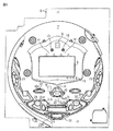
以下、本発明の第1の実施の形態を図面を参照して説明する。まず、遊技機の一例であるパチンコ遊技機の全体の構成について説明する。図1はパチンコ遊技機を正面からみた正面図、図2は遊技盤の前面を示す正面図である。
Embodiment 1 FIG.
Hereinafter, a first embodiment of the present invention will be described with reference to the drawings. First, the overall configuration of a pachinko gaming machine that is an example of a gaming machine will be described. FIG. 1 is a front view of a pachinko gaming machine as viewed from the front, and FIG. 2 is a front view showing the front of the game board.

パチンコ遊技機1は、縦長の方形状に形成された外枠(図示せず)と、外枠の内側に開閉可能に取り付けられた遊技枠とで構成される。また、パチンコ遊技機1は、遊技枠に開閉可能に設けられている額縁状に形成されたガラス扉枠2を有する。遊技枠は、外枠に対して開閉自在に設置される前面枠(図示せず)と、機構部品等が取り付けられる機構板と、それらに取り付けられる種々の部品(後述する遊技盤を除く。)とを含む構造体である。   The pachinko gaming machine 1 includes an outer frame (not shown) formed in a vertically long rectangular shape, and a game frame attached to the inside of the outer frame so as to be opened and closed. Further, the pachinko gaming machine 1 has a glass door frame 2 formed in a frame shape that is provided in the game frame so as to be opened and closed. The game frame includes a front frame (not shown) installed to be openable and closable with respect to the outer frame, a mechanism plate to which mechanism parts and the like are attached, and various parts attached to them (excluding a game board described later). Is a structure including

図1に示すように、パチンコ遊技機1は、額縁状に形成されたガラス扉枠2を有する。ガラス扉枠2の下部表面には打球供給皿(貯留皿)3がある。打球供給皿3の下部には、打球供給皿3に収容しきれない遊技球を貯留する余剰球受皿4と遊技球を発射する打球操作ハンドル(操作ノブ)5が設けられている。ガラス扉枠2の背面には、遊技盤6が着脱可能に取り付けられている。なお、遊技盤6は、それを構成する板状体と、その板状体に取り付けられた種々の部品とを含む構造体である。また、遊技盤6の前面には遊技領域7が形成されている。   As shown in FIG. 1, the pachinko gaming machine 1 has a glass door frame 2 formed in a frame shape. A hitting ball supply tray (storage tray) 3 is provided on the lower surface of the glass door frame 2. Under the hitting ball supply tray 3, an extra ball receiving tray 4 for storing game balls that cannot be accommodated in the hit ball supply tray 3 and a hitting operation handle (operation knob) 5 for launching the game balls are provided. A game board 6 is detachably attached to the back surface of the glass door frame 2. The game board 6 is a structure including a plate-like body constituting the game board 6 and various components attached to the plate-like body. A game area 7 is formed on the front surface of the game board 6.

遊技領域7の中央付近には、それぞれが演出用の飾り図柄(演出図柄)を可変表示する複数の可変表示部を含む演出表示装置(飾り図柄表示装置)9が設けられている。演出表示装置9には、たとえば「左」、「中」、「右」の3つの可変表示部(図柄表示エリア)がある。演出表示装置9は、特別図柄表示器8による特別図柄の可変表示期間中に、装飾用(演出用)の図柄としての演出図柄の可変表示を行なう。演出図柄の可変表示を行なう演出表示装置9は、演出制御基板に搭載されている演出制御用マイクロコンピュータによって制御される。   In the vicinity of the center of the game area 7, there is provided an effect display device (decorative symbol display device) 9 including a plurality of variable display portions each variably displaying an effect decorative symbol (effect symbol). The effect display device 9 has, for example, three variable display portions (symbol display areas) of “left”, “middle”, and “right”. The effect display device 9 variably displays the effect symbol as a symbol for decoration (for effect) during the variable display period of the special symbol by the special symbol indicator 8. The effect display device 9 that performs variable display of effect symbols is controlled by an effect control microcomputer mounted on the effect control board.

演出表示装置9の下部には、始動入賞口14に入った有効入賞球数すなわち保留記憶(始動記憶または始動入賞記憶ともいう。)数を表示する4つの特別図柄保留記憶表示器18が設けられている。特別図柄保留記憶表示器18は、保留記憶数を入賞順に4個まで表示する。特別図柄保留記憶表示器18は、始動入賞口14に始動入賞があるごとに、点灯状態のLEDの数を1増やす。そして、特別図柄保留記憶表示器18は、特別図柄表示器8で可変表示が開始されるごとに、点灯状態のLEDの数を1減らす(すなわち1つのLEDを消灯する)。具体的には、特別図柄保留記憶表示器18は、特別図柄表示器8で可変表示が開始されるごとに、点灯状態をシフトする。なお、この例では、始動入賞口14への入賞による始動記憶数に上限数(4個まで)が設けられているが、上限数を4個以上にしてもよい。   Below the effect display device 9, four special symbol hold memory indicators 18 are provided for displaying the number of effective winning balls that have entered the start winning opening 14, that is, the number of hold memories (also referred to as start memory or start prize memory). ing. The special symbol reservation storage display 18 displays up to four reservation storage numbers in the order of winning. The special symbol hold storage display 18 increases the number of LEDs in the lit state by 1 each time there is a start winning in the start winning opening 14. Then, each time the special symbol display 8 starts variable display, the special symbol hold storage indicator 18 reduces the number of LEDs in the lit state by 1 (that is, turns off one LED). Specifically, the special symbol hold storage display 18 shifts the lighting state each time variable display is started on the special symbol display 8. In this example, the upper limit number (up to 4) is provided for the number of starting memories by winning to the start winning opening 14, but the upper limit number may be four or more.

演出表示装置9の上部には、識別情報としての特別図柄を可変表示する特別図柄表示器(特別図柄表示装置)8が設けられている。この実施の形態では、特別図柄表示器8は、たとえば0〜9の数字を可変表示可能な簡易で小型の表示器(たとえば7セグメントLED)で実現されている。特別図柄表示器8は、遊技者に特定の停止図柄を把握しづらくさせるために、0〜99など、より多種類の数字を可変表示するように構成されていてもよい。また、演出表示装置9は、特別図柄表示器8による特別図柄の可変表示期間中に、装飾用(演出用)の図柄としての演出図柄の可変表示を行なう。   A special symbol display (special symbol display device) 8 that variably displays a special symbol as identification information is provided on the top of the effect display device 9. In this embodiment, the special symbol display 8 is realized by a simple and small display (for example, 7 segment LED) capable of variably displaying numbers 0 to 9, for example. The special symbol display 8 may be configured to variably display a larger number of numbers such as 0 to 99 in order to make it difficult for the player to grasp a specific stop symbol. In addition, the effect display device 9 performs variable display of the effect symbol as a symbol for decoration (for effect) during the variable display period of the special symbol by the special symbol indicator 8.

演出表示装置9の下方には、始動入賞口14を形成する可変入賞球装置15が設けられている。可変入賞球装置15は、羽根を開閉可能に構成され、羽根が開放しているときに遊技球が入賞し易い状態(開状態)となり、羽根が開放していないとき(閉じているとき)に遊技球が入賞し難い状態(閉状態)となる。始動入賞口14に入った入賞球は、遊技盤6の背面に導かれ、始動口スイッチ14a(たとえば、近接スイッチ)によって検出されるとともに、入賞確認スイッチ14b(たとえば、フォトセンサ)によって検出される(なお、逆に、始動口スイッチ14aをフォトセンサを用いて構成し、入賞確認スイッチ14bを近接スイッチを用いて構成してもよいし、近接スイッチやフォトセンサに代えてマイクロスイッチなどの機械式のスイッチを用いてもよい)。なお、この実施の形態では、始動口スイッチ14aによって遊技球が検出されたことに基づいて、乱数回路からの乱数の抽出が行なわれ、特別図柄の変動表示が開始される。また、後述するように、始動口スイッチ14aによる検出結果に加えて入賞確認スイッチ14bの検出結果に基づいて排出異常の発生の有無が判定され、排出異常の発生を検出したことに基づいてセキュリティ信号が外部出力される。また、始動口スイッチ14aによる検出結果に加えて入賞確認スイッチ14bの検出結果に基づいて、後述する入賞信号が外部出力され、賞球個数コマンドが払出制御用マイクロコンピュータ370に送信されて賞球払出が実行される。また、可変入賞球装置15は、ソレノイド16によって開状態にされる。   Below the effect display device 9, a variable winning ball device 15 that forms a start winning opening 14 is provided. The variable winning ball device 15 is configured to be able to open and close the wings, and when the wings are open, the game ball is likely to win a prize (open state), and when the wings are not open (closed). The game ball becomes difficult to win (closed state). The winning ball that has entered the start winning opening 14 is guided to the back of the game board 6 and detected by the start opening switch 14a (for example, a proximity switch) and also by a winning confirmation switch 14b (for example, a photo sensor). (Conversely, the start port switch 14a may be configured using a photo sensor, and the winning confirmation switch 14b may be configured using a proximity switch, or a mechanical type such as a micro switch instead of the proximity switch or the photo sensor. May be used). In this embodiment, the random number is extracted from the random number circuit based on the detection of the game ball by the start port switch 14a, and the special symbol variation display is started. Further, as will be described later, whether or not a discharge abnormality has occurred is determined based on the detection result of the winning check switch 14b in addition to the detection result by the start port switch 14a, and the security signal is detected based on the detection of the discharge abnormality. Is output externally. Further, based on the detection result of the winning confirmation switch 14b in addition to the detection result of the start port switch 14a, a winning signal to be described later is output to the outside, and a winning ball number command is transmitted to the payout control microcomputer 370 for paying out a winning ball. Is executed. The variable winning ball device 15 is opened by a solenoid 16.

なお、可変入賞球装置15の真上に第1始動入賞口を設け、可変入賞球装置15を第2始動入賞口としてもよい。この場合、第1始動入賞口および第2始動入賞口のそれぞれについて、始動口スイッチ(たとえば、近接スイッチ)を設けるとともに入賞確認スイッチ(たとえば、フォトセンサ)を設けるようにしてもよい。そして、第1始動入賞口および第2始動入賞口のそれぞれについて、この実施の形態と同様に、始動口スイッチによって遊技球が検出されたことに基づいて、乱数回路からの乱数の抽出が行なわれ、特別図柄の変動表示が開始されるようにしてもよい。また、第1始動入賞口および第2始動入賞口のそれぞれについて、この実施の形態と同様に、始動口スイッチによる検出結果に加えて入賞確認スイッチの検出結果に基づいて排出異常の発生の有無が判定され、排出異常の発生を検出したことに基づいてセキュリティ信号が外部出力されるようにしてもよい。さらに、第1始動入賞口および第2始動入賞口のそれぞれについて、この実施の形態と同様に、始動口スイッチによる検出結果に加えて入賞確認スイッチの検出結果に基づいて、後述する入賞信号が外部出力され、賞球個数コマンドが払出制御用マイクロコンピュータ370に送信されて賞球払出が実行されるようにしてもよい。   The first winning prize opening may be provided directly above the variable winning ball apparatus 15, and the variable winning ball apparatus 15 may be used as the second starting prize opening. In this case, for each of the first start winning opening and the second starting winning opening, a start opening switch (for example, a proximity switch) and a winning confirmation switch (for example, a photo sensor) may be provided. Then, for each of the first start winning opening and the second starting winning opening, the random number is extracted from the random number circuit based on the detection of the game ball by the start opening switch, as in this embodiment. The special symbol variation display may be started. Further, for each of the first start winning opening and the second starting winning opening, whether or not there is a discharge abnormality based on the detection result of the winning confirmation switch in addition to the detection result by the start opening switch as in this embodiment. The security signal may be externally output based on the determination and the occurrence of the discharge abnormality. Further, for each of the first start winning opening and the second starting winning opening, a winning signal to be described later is generated based on the detection result of the winning confirmation switch in addition to the detection result by the starting opening switch, as in this embodiment. The prize ball number command may be output and sent to the payout control microcomputer 370 to execute the prize ball payout.

可変入賞球装置15の下部には、特定遊技状態(大当り状態)においてソレノイド21によって開状態に制御される開閉板を用いた特別可変入賞球装置20が設けられている。特別可変入賞球装置20は大入賞口を開閉する手段である。特別可変入賞球装置20に入賞し遊技盤6の背面に導かれた入賞球は、カウントスイッチ23(たとえば、近接スイッチ)で検出されるとともに、入賞確認スイッチ23b(たとえば、フォトセンサ)によって検出される(なお、逆に、カウントスイッチ23をフォトセンサを用いて構成し、入賞確認スイッチ23bを近接スイッチを用いて構成してもよいし、近接スイッチやフォトセンサに代えてマイクロスイッチなどの機械式のスイッチを用いてもよい)。なお、この実施の形態では、カウントスイッチ23によって遊技球が検出されたことに基づいて、大当り遊技中に大入賞口に遊技球が入賞したことが検出されるとともに、ラウンドごとに大入賞口への入賞数が所定数(本例では、10個に達したか否か)の判定が行なわれる。また、後述するように、カウントスイッチ23による検出結果に加えて入賞確認スイッチ23bの検出結果に基づいて排出異常の発生の有無が判定され、排出異常の発生を検出したことに基づいてセキュリティ信号が外部出力される。また、カウントスイッチ23による検出結果に加えて入賞確認スイッチ23bの検出結果に基づいて、後述する入賞信号が外部出力され、賞球個数コマンドが払出制御用マイクロコンピュータ370に送信されて賞球払出が実行される。   Below the variable winning ball apparatus 15, a special variable winning ball apparatus 20 using an opening / closing plate that is controlled to be opened by a solenoid 21 in a specific gaming state (big hit state) is provided. The special variable winning ball apparatus 20 is a means for opening and closing the big winning opening. A winning ball that is won by the special variable winning ball device 20 and guided to the back of the game board 6 is detected by a count switch 23 (for example, a proximity switch) and also by a winning confirmation switch 23b (for example, a photo sensor). (Conversely, the count switch 23 may be configured using a photo sensor, the winning confirmation switch 23b may be configured using a proximity switch, or a mechanical type such as a micro switch instead of the proximity switch or the photo sensor. May be used). In this embodiment, based on the fact that the game ball is detected by the count switch 23, it is detected that the game ball has won the big winning opening during the big hit game, and to the big winning opening every round. Is determined to be a predetermined number (in this example, whether or not it has reached 10). Further, as will be described later, the presence / absence of the discharge abnormality is determined based on the detection result of the winning confirmation switch 23b in addition to the detection result by the count switch 23, and the security signal is detected based on the detection of the discharge abnormality. Output externally. Further, based on the detection result of the winning confirmation switch 23b in addition to the detection result of the count switch 23, a winning signal (to be described later) is output to the outside, and a winning ball number command is transmitted to the payout control microcomputer 370 for winning ball winning. Executed.

遊技球がゲート32を通過しゲートスイッチ32aで検出されると、普通図柄表示器10の表示の可変表示が開始される。この実施の形態では、左右のランプ(点灯時に図柄が視認可能になる)が交互に点灯することによって可変表示が行なわれ、たとえば、可変表示の終了時に左側のランプが点灯すれば当たりになる。そして、普通図柄表示器10における停止図柄が所定の図柄(当り図柄)である場合に、可変入賞球装置15が所定回数、所定時間だけ開状態になる。普通図柄表示器10の近傍には、ゲート32を通過した入賞球数を表示する4つのLEDによる表示部を有する普通図柄始動記憶表示器41が設けられている。ゲート32への遊技球の通過があるごとに、普通図柄始動記憶表示器41は点灯するLEDを1増やす。そして、普通図柄表示器10の可変表示が開始されるごとに、点灯するLEDを1減らす。   When the game ball passes through the gate 32 and is detected by the gate switch 32a, variable display of the normal symbol display 10 is started. In this embodiment, variable display is performed by alternately lighting the left and right lamps (a symbol can be visually recognized when the lamp is lit). For example, if the left lamp is lit when the variable display ends, it is a hit. When the stop symbol on the normal symbol display 10 is a predetermined symbol (winning symbol), the variable winning ball device 15 is opened for a predetermined number of times. In the vicinity of the normal symbol display 10, a normal symbol start memory display 41 having a display unit with four LEDs for displaying the number of winning balls that have passed through the gate 32 is provided. Each time there is a game ball passing through the gate 32, the normal symbol start memory display 41 increases the number of LEDs to be turned on by one. Each time the variable display on the normal symbol display 10 is started, the number of LEDs to be lit is reduced by one.

遊技盤6には、複数の入賞口29,30が設けられ、遊技球の入賞口29,30への入賞は、それぞれ入賞口スイッチ29a,30a(たとえば、近接スイッチ)によって検出されるとともに、入賞確認スイッチ29b,30b(たとえば、フォトセンサ)によって検出される(なお、逆に、入賞口スイッチ29a,30aをフォトセンサを用いて構成し、入賞確認スイッチ29b,30bを近接スイッチを用いて構成してもよいし、近接スイッチやフォトセンサに代えてマイクロスイッチなどの機械式のスイッチを用いてもよい)。なお、この実施の形態では、後述するように、入賞口スイッチ29a,30aによる検出結果に加えて入賞確認スイッチ29b,30bの検出結果に基づいて、入賞信号が外部出力され、賞球個数コマンドが払出制御用マイクロコンピュータ370に送信されて賞球払出が実行される。   The game board 6 is provided with a plurality of winning holes 29, 30 and winning of game balls to the winning holes 29, 30 is detected by winning hole switches 29a, 30a (for example, proximity switches), respectively, Detected by confirmation switches 29b and 30b (for example, photosensors) (reversely, winning opening switches 29a and 30a are configured using photosensors, and winning confirmation switches 29b and 30b are configured using proximity switches. Alternatively, a mechanical switch such as a micro switch may be used instead of the proximity switch or the photo sensor). In this embodiment, as will be described later, a winning signal is output to the outside based on the detection results of the winning check switches 29b and 30b in addition to the detection results of the winning opening switches 29a and 30a, and a winning ball number command is output. It is transmitted to the payout control microcomputer 370 and the prize ball payout is executed.

なお、図3に示すように、入賞確認スイッチ14b,23b,29b,30bのうち、少なくとも、入賞口29,30への入賞を検出する入賞確認スイッチ29b,30bについては、遊技枠側に取り付けられている。そのように構成することによって、この実施の形態のように遊技盤6が交換可能に構成されている場合に、遊技枠側に設けられた入賞確認スイッチ29b,30bについては、遊技盤6にかかわらず共通に用いることができ、遊技機のコスト削減を図っている。   As shown in FIG. 3, among the winning confirmation switches 14b, 23b, 29b, 30b, at least the winning confirmation switches 29b, 30b for detecting winning in the winning openings 29, 30 are attached to the game frame side. ing. With this configuration, when the game board 6 is configured to be exchangeable as in this embodiment, the winning confirmation switches 29b and 30b provided on the game frame side are related to the game board 6. It can be used in common, reducing the cost of gaming machines.

なお、この実施の形態では、以下、入賞確認スイッチ14b,23b,29b,30bを区別して指す場合に、それぞれ、入賞確認1スイッチ14b、入賞確認2スイッチ23b、入賞確認3スイッチ29b、および入賞確認4スイッチ30bともいう。   In this embodiment, hereinafter, when the winning confirmation switches 14b, 23b, 29b, 30b are distinguished from each other, the winning confirmation 1 switch 14b, the winning confirmation 2 switch 23b, the winning confirmation 3 switch 29b, and the winning confirmation, respectively. Also referred to as a 4 switch 30b.

各入賞口29,30は、遊技媒体を受け入れて入賞を許容する領域として遊技盤6に設けられる入賞領域を構成している。なお、始動入賞口14や大入賞口も、遊技媒体を受け入れて入賞を許容する入賞領域を構成する。なお、各入賞口29,30に入賞した遊技球を入賞スイッチで検出する構成に代えて、遊技球が所定領域(たとえばゲート)を通過したことを検出スイッチで検出する構成としてもよい。遊技領域7の左右周辺には、遊技中に点滅表示される装飾ランプ25が設けられ、下部には、入賞しなかった遊技球を吸収するアウト口26がある。また、遊技領域7の外側の左右上部には、効果音を発する2つのスピーカ27が設けられている。遊技領域7の外周には、天枠ランプ28a、左枠ランプ28bおよび右枠ランプ28cが設けられている。さらに、遊技領域7における各構造物(大入賞口等)の周囲には装飾LEDが設置されている。天枠ランプ28a、左枠ランプ28bおよび右枠ランプ28cおよび装飾用LEDは、遊技機に設けられている装飾発光体の一例である。なお、この実施の形態では、遊技機に設けられている発光体をランプやLEDを用いて構成する場合を示しているが、この実施の形態で示した態様に限らず、たとえば、遊技機に設けられている発光体を全てLEDを用いて構成するようにしてもよい。   Each of the winning ports 29 and 30 constitutes a winning area provided on the game board 6 as an area for accepting game media and allowing winning. The start winning opening 14 and the big winning opening also constitute a winning area that accepts game media and allows winning. In addition, it may be configured to detect with a detection switch that a game ball has passed a predetermined area (for example, a gate) instead of the configuration in which the game ball won in each of the winning ports 29 and 30 is detected with a prize switch. Around the left and right of the game area 7, there are provided decorative lamps 25 blinking and displayed during the game, and at the lower part there is an outlet 26 for absorbing a game ball that has not won a prize. Two speakers 27 that emit sound effects are provided on the left and right upper portions outside the game area 7. On the outer periphery of the game area 7, a top frame lamp 28a, a left frame lamp 28b, and a right frame lamp 28c are provided. Further, a decoration LED is installed around each structure (such as a big prize opening) in the game area 7. The top frame lamp 28a, the left frame lamp 28b, the right frame lamp 28c, and the decoration LED are examples of a decorative light emitter provided in the gaming machine. In this embodiment, the case where the light emitter provided in the gaming machine is configured by using a lamp or an LED is shown. However, the present invention is not limited to the mode shown in this embodiment. You may make it comprise all the provided light-emitting bodies using LED.

なお、図1および図2では、図示を省略しているが、左枠ランプ28bの近傍に、賞球払出中に点灯する賞球ランプが設けられ、天枠ランプ28aの近傍に、補給球が切れたときに点灯する球切れランプが設けられている。なお、賞球ランプおよび球切れランプは、賞球の払出中である場合や球切れが検出された場合に、演出制御基板に搭載された演出制御用マイクロコンピュータによって点灯制御される。さらに、プリペイドカードが挿入されることによって球貸しを可能にするプリペイドカードユニット(以下、「カードユニット」という。)50が、パチンコ遊技機1に隣接して設置されている。   Although not shown in FIGS. 1 and 2, a prize ball lamp that is turned on during the prize ball payout is provided in the vicinity of the left frame lamp 28b, and a supply ball is provided in the vicinity of the top frame lamp 28a. There is a ball-out lamp that illuminates when it runs out. Note that the award ball lamp and the out-of-ball lamp are controlled to be turned on by the effect control microcomputer mounted on the effect control board when the award ball is being paid out or when the out-of-ball is detected. Further, a prepaid card unit (hereinafter referred to as “card unit”) 50 that enables lending a ball by inserting a prepaid card is installed adjacent to the pachinko gaming machine 1.

カードユニット50には、たとえば、使用可能状態であるか否かを示す使用可表示ランプ、カードユニットがいずれの側のパチンコ遊技機1に対応しているのかを示す連結台方向表示器、カードユニット内にカードが投入されていることを示すカード投入表示ランプ、記録媒体としてのカードが挿入されるカード挿入口、およびカード挿入口の裏面に設けられているカードリーダライタの機構を点検する場合にカードユニットを解放するためのカードユニット錠が設けられている。   The card unit 50 includes, for example, a usable indicator lamp that indicates whether or not the card unit 50 is in a usable state, a connecting table direction indicator that indicates which side of the pachinko gaming machine 1 corresponds to the card unit, and a card unit. When checking the card insertion indicator lamp indicating that a card is inserted in the card, the card insertion slot into which the card as a recording medium is inserted, and the card reader / writer mechanism provided on the back of the card insertion slot A card unit lock for releasing the card unit is provided.

遊技者の操作により打球発射装置から発射された遊技球は、打球レールを通って遊技領域7に入り、その後、遊技領域7を下りてくる。遊技球が始動入賞口14に入り始動口スイッチ14aで検出されると、図柄の可変表示を開始できる状態であれば、特別図柄表示器8において特別図柄が可変表示(変動)を始める。図柄の可変表示を開始できる状態でなければ、保留記憶数を1増やす。   A game ball launched from the ball striking device by the player's operation enters the game area 7 through the hit ball rail, and then descends the game area 7. When the game ball enters the start winning opening 14 and is detected by the start opening switch 14a, the special symbol on the special symbol display 8 starts variable display (variation) if the variable display of the symbol can be started. If the variable display of the symbol cannot be started, the number of reserved memories is increased by one.

特別図柄表示器8における特別図柄の可変表示は、一定時間が経過したときに停止する。停止時の特別図柄(停止図柄)が大当り図柄(特定表示結果)であると、大当り遊技状態に移行する。すなわち、特別可変入賞球装置20が、一定時間経過するまで、または、所定個数(たとえば10個)の遊技球が入賞するまで開放する。そして、特別可変入賞球装置20の開放は、決定されたラウンド数の最後のラウンドまで(たとえば、15ラウンドまで)許容される。   The variable display of the special symbol on the special symbol display device 8 stops when a certain time has elapsed. If the special symbol (stop symbol) at the time of stoppage is a jackpot symbol (specific display result), the game shifts to a jackpot gaming state. That is, the special variable winning ball apparatus 20 is released until a predetermined time elapses or a predetermined number (for example, 10) of gaming balls wins. The opening of the special variable winning ball apparatus 20 is allowed until the last round of the determined number of rounds (for example, up to 15 rounds).

停止時の特別図柄表示器8における特別図柄が確率変動を伴う大当り図柄(確変図柄)である場合には、次に大当りになる確率が高くなる。すなわち、確変状態という遊技者にとってさらに有利な状態になる。   When the special symbol on the special symbol display 8 at the time of stoppage is a jackpot symbol (probability variation symbol) with a probability variation, the probability of the next jackpot increases. That is, it becomes a more advantageous state for the player in the probability variation state.

遊技球がゲート32を通過すると、普通図柄表示器10において普通図柄が可変表示される状態になる。また、普通図柄表示器10における停止図柄が所定の図柄(当り図柄)である場合に、可変入賞球装置15が所定時間だけ開状態になる。   When the game ball passes through the gate 32, the normal symbol display unit 10 enters a state in which the normal symbol is variably displayed. Further, when the stop symbol on the normal symbol display 10 is a predetermined symbol (winning symbol), the variable winning ball device 15 is opened for a predetermined time.

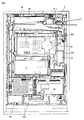
次に、パチンコ遊技機1の裏面の構造について図4を参照して説明する。図4は、遊技機を裏面から見た背面図である。図4に示すように、パチンコ遊技機1裏面側では、演出表示装置9を制御する演出制御用マイクロコンピュータ100が搭載された演出制御基板80を含む変動表示制御ユニット、遊技制御用マイクロコンピュータ等が搭載された遊技制御基板(主基板)31、音声出力基板70、ランプドライバ基板35、および球払出制御を行なう払出制御用マイクロコンピュータ等が搭載された払出制御基板37等の各種基板が設置されている。なお、遊技制御基板31は基板収納ケース200に収納されている。   Next, the structure of the back surface of the pachinko gaming machine 1 will be described with reference to FIG. FIG. 4 is a rear view of the gaming machine as seen from the back side. As shown in FIG. 4, on the back side of the pachinko gaming machine 1, there are a variable display control unit including an effect control board 80 on which an effect control microcomputer 100 for controlling the effect display device 9 is mounted, a game control microcomputer, and the like. Various boards such as a mounted game control board (main board) 31, an audio output board 70, a lamp driver board 35, and a payout control board 37 mounted with a payout control microcomputer for performing ball payout control are installed. Yes. The game control board 31 is stored in the board storage case 200.

さらに、パチンコ遊技機1裏面側には、DC30V、DC21V、DC12VおよびDC5V等の各種電源電圧を作成する電源回路が搭載された電源基板910やタッチセンサ基板91が設けられている。電源基板910には、パチンコ遊技機1における遊技制御基板31および各電気部品制御基板(演出制御基板80および払出制御基板37)やパチンコ遊技機1に設けられている各電気部品(電力が供給されることによって動作する部品)への電力供給を実行あるいは遮断するための電力供給許可手段としての電源スイッチ、遊技制御基板31の遊技制御用マイクロコンピュータ560のRAM55をクリアするためのクリアスイッチが設けられている。さらに、電源スイッチの内側(基板内部側)には、交換可能なヒューズが設けられている。   Further, on the back side of the pachinko gaming machine 1, a power supply substrate 910 and a touch sensor substrate 91 on which power supply circuits for generating various power supply voltages such as DC30V, DC21V, DC12V, and DC5V are mounted. The power supply board 910 is supplied with the game control board 31 and each electrical component control board (the effect control board 80 and the payout control board 37) in the pachinko gaming machine 1 and each electrical component (power is supplied) provided in the pachinko gaming machine 1. A power switch as a power supply permission means for executing or shutting off the power supply to the component), and a clear switch for clearing the RAM 55 of the game control microcomputer 560 of the game control board 31 are provided. ing. Further, a replaceable fuse is provided inside the power switch (inside the substrate).

なお、この実施の形態では、主基板31は遊技盤側に設けられ、払出制御基板37は遊技枠側に設けられている。このような構成であっても、後述するように、主基板31と払出制御基板37との間の通信をシリアル通信で行なうことによって、遊技盤を交換する際の配線の取り回しを容易にしている。   In this embodiment, the main board 31 is provided on the game board side, and the payout control board 37 is provided on the game frame side. Even in such a configuration, as will be described later, the communication between the main board 31 and the payout control board 37 is performed by serial communication, thereby facilitating the routing of the wiring when replacing the game board. .

なお、各制御基板には、制御用マイクロコンピュータを含む制御手段が搭載されている。制御手段は、遊技制御手段等からのコマンドとしての指令信号(制御信号)に従って遊技機に設けられている電気部品(遊技用装置:球払出装置97、演出表示装置9、ランプやLEDなどの発光体、スピーカ27等)を制御する。以下、主基板31を制御基板に含めて説明を行なうことがある。その場合には、制御基板に搭載される制御手段は、遊技制御手段と、遊技制御手段等からの指令信号に従って遊技機に設けられている電気部品を制御する手段とのそれぞれを指す。また、主基板31以外のマイクロコンピュータが搭載された基板を“サブ基板”ということがある。なお、球払出装置97は、遊技球を誘導する通路とステッピングモータ等により駆動されるスプロケット等によって誘導された遊技球を貯留皿や下皿に払い出すための装置であって、払い出された賞球や貸し球をカウントする払出個数カウントスイッチ等もユニットの一部として構成されている。なお、この実施の形態では、払出検出手段は、払出個数カウントスイッチ301によって実現され、球払出装置97から実際に賞球や貸し球が払い出されたことを検出する機能を備える。この場合、払出個数カウントスイッチ301は、賞球や貸し球の払い出しを1球検出するごとに検出信号を出力する。   Each control board is equipped with control means including a control microcomputer. The control means is an electrical component (game device: ball payout device 97, effect display device 9, light emission from a lamp, LED, etc.) provided in the gaming machine according to a command signal (control signal) as a command from the game control means or the like. Body, speaker 27, etc.). Hereinafter, description may be made with the main board 31 included in the control board. In that case, the control means mounted on the control board refers to each of the game control means and the means for controlling the electrical components provided in the gaming machine in accordance with a command signal from the game control means or the like. A substrate on which a microcomputer other than the main substrate 31 is mounted may be referred to as a “sub-substrate”. The ball payout device 97 is a device for paying out a game ball guided by a passage for guiding a game ball and a sprocket driven by a stepping motor or the like to a storage tray or a lower plate. A payout number counting switch for counting prize balls and rental balls is also configured as part of the unit. In this embodiment, the payout detection means is realized by the payout number count switch 301 and has a function of detecting that a winning ball or a lending ball is actually paid out from the ball payout device 97. In this case, the payout number count switch 301 outputs a detection signal every time one payout of prize balls or rental balls is detected.

パチンコ遊技機1裏面において、上方には、各種情報をパチンコ遊技機1の外部に出力するための各端子を備えたターミナル基板160が設置されている。ターミナル基板160には、たとえば、大当り遊技状態の発生を示す大当り情報等の情報出力信号(図32に示す図柄確定回数1信号、始動口信号、大当り1信号、大当り2信号、大当り3信号、時短信号、入賞信号、セキュリティ信号、高確中信号、賞球情報)を外部出力するための情報出力端子が設けられている。   On the back side of the pachinko gaming machine 1, a terminal board 160 having terminals for outputting various information to the outside of the pachinko gaming machine 1 is installed above. The terminal board 160 has, for example, an information output signal such as jackpot information indicating the occurrence of a jackpot gaming state (symbol determination frequency 1 signal shown in FIG. 32, start port signal, jackpot 1 signal, jackpot 2 signal, jackpot 3 signal, hour An information output terminal for externally outputting a short signal, a winning signal, a security signal, a high-accuracy signal, and winning ball information) is provided.

貯留タンク38に貯留された遊技球は誘導レール(図示せず)を通り、カーブ樋を経て払出ケース40Aで覆われた球払出装置97に至る。球払出装置97の上方には、遊技媒体切れ検出手段としての球切れスイッチ187が設けられている。球切れスイッチ187が球切れを検出すると、球払出装置97の払出動作が停止する。球切れスイッチ187は遊技球通路内の遊技球の有無を検出するスイッチであるが、貯留タンク38内の補給球の不足を検出する球切れ検出スイッチ167も誘導レールにおける上流部分(貯留タンク38に近接する部分)に設けられている。球切れ検出スイッチ167が遊技球の不足を検知すると、遊技機設置島に設けられている補給機構からパチンコ遊技機1に対して遊技球の補給が行なわれる。   The game ball stored in the storage tank 38 passes through a guide rail (not shown), and reaches a ball payout device 97 covered with a payout case 40A through a curve rod. Above the ball payout device 97, a ball break switch 187 is provided as a game medium break detection means. When the ball break switch 187 detects a ball break, the payout operation of the ball payout device 97 stops. The ball break switch 187 is a switch for detecting the presence or absence of a game ball in the game ball passage, but the ball break detection switch 167 for detecting the shortage of supply balls in the storage tank 38 is also an upstream portion of the guide rail (in the storage tank 38). (Proximate part). When the ball break detection switch 167 detects a shortage of game balls, the game balls are replenished to the pachinko gaming machine 1 from the replenishment mechanism provided on the gaming machine installation island.

入賞に基づく景品としての遊技球や球貸し要求に基づく遊技球が多数払出されて打球供給皿3が満杯になると、遊技球は、余剰球誘導通路を経て余剰球受皿4に導かれる。さらに遊技球が払出されると、感知レバー(図示せず)が貯留状態検出手段としての満タン検出スイッチ45を押圧して、貯留状態検出手段としての満タン検出スイッチ45がオンする。その状態では、球払出装置内の払出モータの回転が停止して球払出装置の動作が停止するとともに打球発射装置の駆動も停止する。   When a large number of game balls as prizes based on winning prizes or game balls based on ball lending requests are paid out and the hitting ball supply tray 3 is full, the game balls are guided to the surplus ball receiving tray 4 through the surplus ball guide passage. When the game ball is further paid out, a sensing lever (not shown) presses the full tank detection switch 45 as the storage state detection means, and the full tank detection switch 45 as the storage state detection means is turned on. In this state, the rotation of the payout motor in the ball payout device is stopped, the operation of the ball payout device is stopped, and the driving of the ball hitting device is also stopped.

次に、各入賞口の断面構造の具体例の一例として、始動入賞口14内の断面構造の具体例を説明する。なお、一例として始動入賞口14内の断面構造について説明するが、大入賞口や入賞口29,30についても、およそ同様の断面構造でカウントスイッチ23や入賞口スイッチ29a,30aが上流側に配置され、入賞確認スイッチ23b,29b,30bが下流側に配置されている。ただし、入賞口29,30に関しては、上流側に配置される入賞口スイッチ29a,30aと、下流側に配置される入賞確認スイッチ29b,30bとの距離が多少離れていても支障が生じる処理はないので、既に図3で説明したように、少なくとも、入賞確認スイッチ29b,30bについては遊技枠側に配置され、遊技機のコスト低減を図っている。   Next, a specific example of the cross-sectional structure in the start winning port 14 will be described as an example of the cross-sectional structure of each winning port. In addition, although the cross-sectional structure in the start winning opening 14 will be described as an example, the count switch 23 and the winning opening switches 29a and 30a are arranged on the upstream side in the large winning opening and the winning openings 29 and 30 with substantially the same cross-sectional structure. The winning confirmation switches 23b, 29b, 30b are arranged on the downstream side. However, with respect to the winning ports 29 and 30, the processing that causes trouble even if the distance between the winning port switches 29a and 30a arranged on the upstream side and the winning check switches 29b and 30b arranged on the downstream side is slightly separated. Therefore, as already described with reference to FIG. 3, at least the winning confirmation switches 29b and 30b are arranged on the game frame side to reduce the cost of the gaming machine.

図5は、始動入賞口14内の断面構造の具体例を示す説明図である。図5に示すように、始動入賞口14内には、始動入賞口内に入賞した遊技球を検出可能な2つのスイッチ(始動口スイッチ14aと入賞確認スイッチ14b)が設けられている。この実施の形態では、図5に示すように、始動入賞口14内で、始動口スイッチ14aと入賞確認スイッチ14bとが上下に配置されている(本例では、始動口スイッチ14aが上側に配置され、入賞確認スイッチ14bが下側に配置されている)。従って、この実施の形態では、始動入賞口14内に入賞した遊技球は、遊技盤6の背面に導かれ、まず始動口スイッチ14aで検出され、次いで入賞確認スイッチ14bで検出される。なお、下流側の入賞確認スイッチ14bの配置に関して、遊技球が入賞側の開口部分から入賞したあと排出側の開口部分から排出される経路において、できるだけ排出側の開口部分に近い位置に配置されていれば、配置位置の高低などは問わない。   FIG. 5 is an explanatory diagram showing a specific example of a cross-sectional structure in the start winning opening 14. As shown in FIG. 5, the start winning opening 14 is provided with two switches (start opening switch 14a and winning confirmation switch 14b) capable of detecting a game ball won in the starting winning opening. In this embodiment, as shown in FIG. 5, the start opening switch 14a and the winning confirmation switch 14b are arranged vertically in the start winning opening 14 (in this example, the start opening switch 14a is arranged on the upper side). And a winning confirmation switch 14b is arranged on the lower side). Therefore, in this embodiment, the game ball won in the start winning opening 14 is guided to the back of the game board 6 and is first detected by the start opening switch 14a and then detected by the winning confirmation switch 14b. Regarding the arrangement of the downstream winning confirmation switch 14b, the game ball is arranged as close as possible to the discharging side opening part in the path where the game ball is discharged from the winning side opening part and then discharged from the discharging side opening part. If it is, the height of an arrangement position etc. does not ask | require.

また、始動口スイッチ14aと入賞確認スイッチ14bとして、それぞれ異なる検出方式のスイッチが用いられる。この実施の形態では、始動口スイッチ14aとして近接スイッチを用い、入賞確認スイッチ14bとしてフォトセンサを用いる場合を示している。   Also, different detection system switches are used as the start port switch 14a and the winning confirmation switch 14b. In this embodiment, a case where a proximity switch is used as the start port switch 14a and a photo sensor is used as the winning confirmation switch 14b is shown.

また、この実施の形態では、始動口スイッチ14aによって遊技球が検出されたことに基づいて、乱数回路からの乱数の抽出が行なわれ、特別図柄の変動表示が開始される。また、後述するように、始動口スイッチ14aによる検出結果に加えて入賞確認スイッチ14bの検出結果に基づいて排出異常の発生の有無が判定され、排出異常の発生を検出したことに基づいてセキュリティ信号が外部出力される。また、始動口スイッチ14aによる検出結果に加えて入賞確認スイッチ14bの検出結果に基づいて、後述する入賞信号が外部出力され、賞球個数コマンドが払出制御用マイクロコンピュータ370に送信されて賞球払出が実行される。   In this embodiment, the random number is extracted from the random number circuit based on the detection of the game ball by the start port switch 14a, and the special symbol variation display is started. Further, as will be described later, whether or not a discharge abnormality has occurred is determined based on the detection result of the winning check switch 14b in addition to the detection result by the start port switch 14a, and the security signal is detected based on the detection of the discharge abnormality. Is output externally. Further, based on the detection result of the winning confirmation switch 14b in addition to the detection result of the start port switch 14a, a winning signal to be described later is output to the outside, and a winning ball number command is transmitted to the payout control microcomputer 370 for paying out a winning ball. Is executed.

なお、始動口スイッチ14aおよび入賞確認スイッチ14bの検出方式は、この実施の形態で示したものに限らず、たとえば、始動口スイッチ14aと入賞確認スイッチ14bとで異なる検出方式であれば、逆に始動口スイッチ14aとしてフォトセンサを用い、入賞確認スイッチ14bとして近接スイッチを用いてもよい。この場合、フォトセンサである始動口スイッチ14aの検出結果に基づいて乱数回路からの乱数の抽出や特別図柄の変動表示が実行され、フォトセンサである始動口スイッチ14aの検出結果に加えて近接スイッチである入賞確認スイッチ14bの検出結果に基づいて、始動入賞口14の排出異常の判定や、入賞信号の外部出力、賞球払出が実行されることになる。また、たとえば、電磁式のスイッチである近接スイッチや光学式のフォトセンサに代えて、始動口スイッチ14aまたは入賞確認スイッチ14bとして、機械式のスイッチ(マイクロスイッチなど)を用いてもよい。   The detection method of the start port switch 14a and the winning confirmation switch 14b is not limited to that shown in this embodiment. For example, if the detection method is different between the starting port switch 14a and the winning confirmation switch 14b, the detection method is reversed. A photo sensor may be used as the start port switch 14a, and a proximity switch may be used as the winning confirmation switch 14b. In this case, the random number is extracted from the random number circuit or the special symbol is changed based on the detection result of the start port switch 14a which is a photo sensor, and the proximity switch is added to the detection result of the start port switch 14a which is a photo sensor. On the basis of the detection result of the winning confirmation switch 14b, the determination of the discharge abnormality of the start winning opening 14, the external output of the winning signal, and the payout of the winning ball are executed. In addition, for example, a mechanical switch (such as a micro switch) may be used as the start port switch 14a or the winning confirmation switch 14b instead of the proximity switch or the optical photo sensor that is an electromagnetic switch.

図6は、遊技球を検出可能な検出手段の方式を説明するための回路図である。図6(A)には、始動口スイッチ14a(近接スイッチ)が示されている。始動口スイッチ14aの一方の端子には、電源基板910から+12V電源電圧が供給されている。始動口スイッチ14aの他方の端子の電圧レベルである検出信号は、主基板31に入力される。主基板31において、検出信号は、入力ドライバ回路から遊技制御用マイクロコンピュータの入力ポートに入力される。また、始動口スイッチ14aの出力側には、一端が接地されている抵抗RとコンデンサCが接続されている。   FIG. 6 is a circuit diagram for explaining a method of detection means capable of detecting a game ball. FIG. 6A shows a start port switch 14a (proximity switch). The + 12V power supply voltage is supplied from the power supply board 910 to one terminal of the start port switch 14a. A detection signal that is the voltage level of the other terminal of the start port switch 14 a is input to the main board 31. In the main board 31, the detection signal is input from the input driver circuit to the input port of the game control microcomputer. A resistor R and a capacitor C, one end of which is grounded, are connected to the output side of the start port switch 14a.

近接スイッチである始動口スイッチ14aに設けられている穴を金属の遊技球が通過するとコイルLに逆起電力が生じ、コイルLの等価的な抵抗値が極めて大きくなる。従って、始動口スイッチ14aの出力は、0Vに近いローレベルになる。すなわち、検出信号は、ローレベルである。始動口スイッチ14aに設けられている穴を金属の遊技球が通過していない場合には、始動口スイッチ14aの出力は、+12VがコイルLと抵抗Rの抵抗値で分圧された値であり、ハイレベルであるとみなされるしきい値レベルを越える。すなわち、検出信号は、ハイレベルである。従って、この実施の形態では、遊技制御用マイクロコンピュータは、始動口スイッチ14aからの出力がハイレベルであれば始動口スイッチ14aがオフ状態であると判断することができ、始動口スイッチ14aからの出力がローレベルであれば始動口スイッチ14aがオン状態であると判断することができる(すなわち、始動口スイッチ14aの出力は負論理となっている)。なお、検出信号のレベルを入力ドライバ回路で論理反転してから遊技制御用マイクロコンピュータ560に入力するように構成してもよい。   When a metal game ball passes through a hole provided in the start port switch 14a which is a proximity switch, a counter electromotive force is generated in the coil L, and the equivalent resistance value of the coil L becomes extremely large. Accordingly, the output of the start port switch 14a becomes a low level close to 0V. That is, the detection signal is at a low level. When the metal game ball does not pass through the hole provided in the start port switch 14a, the output of the start port switch 14a is a value obtained by dividing + 12V by the resistance value of the coil L and the resistance R. Exceed a threshold level, which is considered to be high. That is, the detection signal is at a high level. Therefore, in this embodiment, the game control microcomputer can determine that the start port switch 14a is in the OFF state if the output from the start port switch 14a is at a high level. If the output is at a low level, it can be determined that the start port switch 14a is in the ON state (that is, the output of the start port switch 14a is negative logic). The detection signal level may be logically inverted by the input driver circuit and then input to the game control microcomputer 560.

なお、この実施の形態では、大入賞口に関しては、カウントスイッチ23の検出信号のレベルが入力ドライバ回路で論理反転してから遊技制御用マイクロコンピュータ560に入力される。従って、この実施の形態では、遊技制御用マイクロコンピュータは、カウントスイッチ23からの出力(論理反転後の出力)がローレベルであればカウントスイッチ23がオフ状態であると判断することができ、カウントスイッチ23からの出力(論理反転後の出力)がハイレベルであればカウントスイッチ23がオン状態であると判断することができる。   In this embodiment, the level of the detection signal of the count switch 23 is input to the game control microcomputer 560 after the logic of the input signal is inverted by the input driver circuit for the special winning opening. Therefore, in this embodiment, the game control microcomputer can determine that the count switch 23 is in the OFF state if the output from the count switch 23 (output after logic inversion) is at a low level. If the output from the switch 23 (output after logic inversion) is at a high level, it can be determined that the count switch 23 is on.

また、この実施の形態では、入賞口29,30に関しては、入賞口スイッチ29a,30aの検出信号のレベルが入力ドライバ回路で論理反転してから遊技制御用マイクロコンピュータ560に入力される。従って、この実施の形態では、遊技制御用マイクロコンピュータは、入賞口スイッチ29a,30aからの出力(論理反転後の出力)がローレベルであれば入賞口スイッチ29a,30aがオフ状態であると判断することができ、入賞口スイッチ29a,30aからの出力(論理反転後の出力)がハイレベルであれば入賞口スイッチ29a,30aがオン状態であると判断することができる。   In this embodiment, the levels of the detection signals of the winning opening switches 29a and 30a are logically inverted by the input driver circuit and input to the game control microcomputer 560 for the winning openings 29 and 30. Therefore, in this embodiment, the game control microcomputer determines that the winning opening switches 29a and 30a are in the OFF state if the output from the winning opening switches 29a and 30a (output after logic inversion) is at a low level. If the outputs from the winning opening switches 29a and 30a (output after logic inversion) are at a high level, it can be determined that the winning opening switches 29a and 30a are in the ON state.

図6(B)には、入賞確認スイッチ14b(フォトセンサ)が示されている。図6(B)に示すフォトセンサは、発光する発光ダイオード(LED)341と、受光して電流を出力するフォトトランジスタ342とで構成されている。発光ダイオード341およびフォトトランジスタ342の近傍を遊技球が通過すると、遊技球が反射した発光ダイオード341からの光をフォトトランジスタ342が受光して出力側に電流を流す。なお、この場合、フォトトランジスタ342のコレクタ端子からエミッタ端子の向きに電流が流れることにより、フォトセンサの検出信号は、近接スイッチと同様に負論理である。ただし、この実施の形態では、入賞確認スイッチ14bの検出信号は、入力ドライバ回路で論理反転してから遊技制御用マイクロコンピュータ560に入力される。従って、この実施の形態では、遊技制御用マイクロコンピュータは、入賞確認スイッチ14bからの出力(論理反転後の出力)がローレベルであれば入賞確認スイッチ14bがオフ状態であると判断することができ、入賞確認スイッチ14bからの出力(論理反転後の出力)がハイレベルであれば入賞確認スイッチ14bがオン状態であると判断することができる。   FIG. 6B shows a winning confirmation switch 14b (photo sensor). The photosensor illustrated in FIG. 6B includes a light-emitting diode (LED) 341 that emits light and a phototransistor 342 that receives light and outputs current. When the game ball passes in the vicinity of the light-emitting diode 341 and the phototransistor 342, the phototransistor 342 receives light from the light-emitting diode 341 reflected by the game ball and causes a current to flow to the output side. In this case, since a current flows from the collector terminal of the phototransistor 342 toward the emitter terminal, the detection signal of the photosensor is negative logic as in the proximity switch. However, in this embodiment, the detection signal of the winning confirmation switch 14b is logically inverted by the input driver circuit and then input to the game control microcomputer 560. Therefore, in this embodiment, the game control microcomputer can determine that the winning confirmation switch 14b is in an OFF state if the output from the winning confirmation switch 14b (output after logic inversion) is at a low level. If the output from the winning confirmation switch 14b (output after logic inversion) is at a high level, it can be determined that the winning confirmation switch 14b is in the on state.

なお、この実施の形態では、入賞確認スイッチ23b,29b,30bの検出信号も、同様に、入力ドライバ回路で論理反転してから遊技制御用マイクロコンピュータ560に入力される。従って、この実施の形態では、遊技制御用マイクロコンピュータは、入賞確認スイッチ23b,29b,30bからの出力(論理反転後の出力)がローレベルであれば入賞確認スイッチ23b,29b,30bがオフ状態であると判断することができ、入賞確認スイッチ23b,29b,30bからの出力(論理反転後の出力)がハイレベルであれば入賞確認スイッチ23b,29b,30bがオン状態であると判断することができる。   In this embodiment, the detection signals of the winning confirmation switches 23b, 29b, and 30b are similarly logically inverted by the input driver circuit and then input to the game control microcomputer 560. Therefore, in this embodiment, the game control microcomputer is in the off state if the winning confirmation switches 23b, 29b, and 30b are in the OFF state if the outputs from the winning confirmation switches 23b, 29b, and 30b (output after logic inversion) are at a low level. If the output from the winning confirmation switches 23b, 29b, 30b (output after logic inversion) is at a high level, it is determined that the winning confirmation switches 23b, 29b, 30b are on. Can do.

なお、この実施の形態では、フォトセンサとして反射型のフォトセンサが用いられるが、図6(C)における上段に示すように、発光素子(LED341)と受光素子(フォトトランジスタ342)とを入賞球経路を挟むように対向させて設置し、遊技球が発光素子からの光を遮ることによって受光素子が光を検出しなくなることによって、発光素子と受光素子との間を通過した遊技球を検出する透過型のフォトセンサを用いてもよい。透過型のフォトセンサを用いる場合に、図6(C)における下段に示すように、発光素子の光軸(図6(C)において黒丸で例示されている。)が、遊技球経路(入賞球経路)を通過する遊技球の中央部からずれるように、発光素子および受光素子を設置することが好ましい。光軸が遊技球の中央部に相当するように設置する場合に比べて、連続して通過する2つの遊技球の間隔が相対的に広い部分(図6(C)における「空隙」の部分)において遊技球を検知することができ、2つの遊技球を別個に検出しやすいからである。同様の理由で、図6(B)に例示する反射型のフォトセンサを用いる場合にも、発光素子からの光の反射点が遊技球の中央部からずれるように、発光素子および受光素子を設置することが好ましい。   In this embodiment, a reflective photosensor is used as the photosensor. However, as shown in the upper part of FIG. 6C, a light-emitting element (LED 341) and a light-receiving element (phototransistor 342) are used as winning balls. The game balls that have been installed so as to face each other and the game ball blocks light from the light emitting element and the light receiving element does not detect the light, thereby detecting the game ball that has passed between the light emitting element and the light receiving element. A transmissive photosensor may be used. When a transmissive photosensor is used, as shown in the lower part of FIG. 6C, the optical axis of the light emitting element (illustrated by a black circle in FIG. 6C) is a game ball path (winning ball). It is preferable to install the light emitting element and the light receiving element so as to deviate from the center of the game ball passing through the route. Compared with the case where the optical axis corresponds to the central portion of the game ball, a portion where the interval between two game balls passing through is relatively wide (the “void” portion in FIG. 6C). This is because the game ball can be detected at, and the two game balls can be easily detected separately. For the same reason, when using the reflective photosensor illustrated in FIG. 6B, the light emitting element and the light receiving element are installed so that the reflection point of the light from the light emitting element is shifted from the center of the game ball. It is preferable to do.

図7は、主基板(遊技制御基板)31における回路構成の一例を示すブロック図である。なお、図7には、払出制御基板37および演出制御基板80等も示されている。主基板31には、プログラムに従ってパチンコ遊技機1を制御する遊技制御用マイクロコンピュータ(遊技制御手段に相当)560、制御用クロック生成回路111、および乱数用クロック生成回路112が搭載されている。遊技制御用マイクロコンピュータ560は、ゲーム制御(遊技進行制御)用のプログラム等を記憶するROM54、ワークメモリとして使用される記憶手段としてのRAM55、プログラムに従って制御動作を行なうCPU56およびI/Oポート部57を含む。この実施の形態では、ROM54およびRAM55は遊技制御用マイクロコンピュータ560に内蔵されている。すなわち、遊技制御用マイクロコンピュータ560は、1チップマイクロコンピュータである。1チップマイクロコンピュータには、少なくともRAM55が内蔵されていればよく、ROM54は外付けであっても内蔵されていてもよい。また、I/Oポート部57は、外付けであってもよい。さらに、ハードウェア乱数(ハードウェア回路が発生する乱数)を発生する乱数回路509が内蔵されている。   FIG. 7 is a block diagram showing an example of a circuit configuration in the main board (game control board) 31. FIG. 7 also shows the payout control board 37, the effect control board 80, and the like. On the main board 31, a game control microcomputer (corresponding to a game control means) 560 for controlling the pachinko gaming machine 1 according to a program, a control clock generation circuit 111, and a random number clock generation circuit 112 are mounted. The game control microcomputer 560 includes a ROM 54 for storing a game control (game progress control) program and the like, a RAM 55 as storage means used as a work memory, a CPU 56 for performing control operations in accordance with the program, and an I / O port unit 57. including. In this embodiment, the ROM 54 and the RAM 55 are built in the game control microcomputer 560. That is, the game control microcomputer 560 is a one-chip microcomputer. The one-chip microcomputer only needs to include at least the RAM 55, and the ROM 54 may be external or internal. The I / O port unit 57 may be externally attached. Furthermore, a random number circuit 509 for generating hardware random numbers (random numbers generated by the hardware circuit) is incorporated.

ここで、制御用クロック生成回路111は、遊技制御用マイクロコンピュータ560の外部にて、所定周波数の発振信号となる制御用クロックCCLKを生成する。制御用クロック生成回路111により生成された制御用クロックCCLKは、たとえば、遊技制御用マイクロコンピュータ560の制御用外部クロック端子EXCを介してクロック回路502に供給される。乱数用クロック生成回路112は、遊技制御用マイクロコンピュータ560の外部にて、制御用クロックCCLKの発振周波数とは異なる所定周波数の発振信号となる乱数用クロックRCLKを生成する。乱数用クロック生成回路112により生成された乱数用クロックRCLKは、たとえば、遊技制御用マイクロコンピュータ560の乱数用外部クロック端子ERCを介して乱数回路509に供給される。一例として、乱数用クロック生成回路112により生成される乱数用クロックRCLKの発振周波数は、制御用クロック生成回路111により生成される制御用クロックCCLKの発振周波数以下となるようにすればよい。あるいは、乱数用クロック生成回路112により生成される乱数用クロックRCLKの発振周波数は、制御用クロック生成回路111により生成される制御用クロックCCLKの発振周波数よりも高周波となるようにしてもよい。   Here, the control clock generation circuit 111 generates a control clock CCLK that becomes an oscillation signal of a predetermined frequency outside the game control microcomputer 560. The control clock CCLK generated by the control clock generation circuit 111 is supplied to the clock circuit 502 via the control external clock terminal EXC of the game control microcomputer 560, for example. The random number clock generation circuit 112 generates a random number clock RCLK that is an oscillation signal having a predetermined frequency different from the oscillation frequency of the control clock CCLK, outside the game control microcomputer 560. The random number clock RCLK generated by the random number clock generation circuit 112 is supplied to the random number circuit 509 via the random number external clock terminal ERC of the game control microcomputer 560, for example. As an example, the oscillation frequency of the random number clock RCLK generated by the random number clock generation circuit 112 may be equal to or lower than the oscillation frequency of the control clock CCLK generated by the control clock generation circuit 111. Alternatively, the oscillation frequency of the random number clock RCLK generated by the random number clock generation circuit 112 may be higher than the oscillation frequency of the control clock CCLK generated by the control clock generation circuit 111.

なお、遊技制御用マイクロコンピュータ560においてCPU56がROM54に格納されているプログラムに従って制御を実行するので、以下、遊技制御用マイクロコンピュータ560(またはCPU56)が実行する(または、処理を行なう)ということは、具体的には、CPU56がプログラムに従って制御を実行することである。このことは、主基板31以外の他の基板に搭載されているマイクロコンピュータについても同様である。   In the game control microcomputer 560, the CPU 56 executes control in accordance with the program stored in the ROM 54. Therefore, the game control microcomputer 560 (or the CPU 56) executes (or performs processing) hereinafter. Specifically, the CPU 56 executes control according to a program. The same applies to microcomputers mounted on substrates other than the main substrate 31.

遊技制御用マイクロコンピュータ560は、始動口スイッチ14aへの始動入賞が生じたときに乱数回路509から数値データをランダムRとして読み出し、特別図柄および演出図柄の変動開始時にランダムRに基づいて特定の表示結果としての大当り表示結果にするか否か、すなわち、大当りとするか否かを決定する。そして、大当りとすると決定したときに、遊技状態を遊技者にとって有利な特定遊技状態としての大当り遊技状態に移行させる。   The game control microcomputer 560 reads numerical data from the random number circuit 509 as a random R when a start winning to the start port switch 14a occurs, and performs a specific display based on the random R at the start of the variation of the special symbol and the production symbol. It is determined whether or not to make a jackpot display result as a result, that is, whether or not to make a jackpot. Then, when it is determined to be a big hit, the gaming state is shifted to a big hit gaming state as a specific gaming state advantageous to the player.

また、遊技制御用マイクロコンピュータ560には、払出制御基板37(の払出制御用マイクロコンピュータ370)とシリアル通信で信号を入出力(送受信)するためのシリアル通信回路511が内蔵されている。なお、払出制御用マイクロコンピュータ370にも、遊技制御用マイクロコンピュータ560とシリアル通信で信号を入出力するためのシリアル通信回路が内蔵されている。   The game control microcomputer 560 has a built-in serial communication circuit 511 for inputting / outputting (transmitting / receiving) signals with the payout control board 37 (the payout control microcomputer 370) through serial communication. The payout control microcomputer 370 also includes a serial communication circuit for inputting / outputting signals through the game control microcomputer 560 through serial communication.

なお、この実施の形態では、遊技制御用マイクロコンピュータ560と払出制御用マイクロコンピュータ370との間でシリアル通信を行なう場合を示しているが、演出制御基板80側にもシリアル通信回路を搭載するようにし、遊技制御用マイクロコンピュータ560は、シリアル通信方式を用いて演出制御コマンドを演出制御用マイクロコンピュータ100に送信するように制御してもよい。   In this embodiment, serial communication is performed between the game control microcomputer 560 and the payout control microcomputer 370. However, a serial communication circuit is also mounted on the effect control board 80 side. In addition, the game control microcomputer 560 may be controlled to transmit the effect control command to the effect control microcomputer 100 using a serial communication method.

また、RAM55は、その一部または全部が電源基板において作成されるバックアップ電源によってバックアップされている不揮発性記憶手段としてのバックアップRAMである。すなわち、遊技機に対する電力供給が停止しても、所定期間(バックアップ電源としてのコンデンサが放電してバックアップ電源が電力供給不能になるまで)は、RAM55の一部または全部の内容は保存される。特に、少なくとも、遊技状態すなわち遊技制御手段の制御状態に応じたデータ(特別図柄プロセスフラグや、保留記憶数をカウントするための保留記憶数カウンタの値など)と未払出賞球数を示すデータ(具体的には、後述する賞球コマンド出力カウンタの値)は、バックアップRAMに保存される。遊技制御手段の制御状態に応じたデータとは、停電等が生じた後に復旧した場合に、そのデータに基づいて、遊技を再開させるために必要なデータである。また、制御状態に応じたデータと未払出賞球数を示すデータとを遊技の進行状態を示すデータと定義する。また、この実施の形態では、排出異常が発生した場合に後述する排出異常フラグがセットされるのであるが、この排出異常フラグもバックアップRAMに記憶されバックアップされる。なお、この実施の形態では、RAM55の全部が、電源バックアップされているとする。   The RAM 55 is a backup RAM as a non-volatile storage means, part or all of which is backed up by a backup power supply created on the power supply board. That is, even if the power supply to the gaming machine is stopped, a part or all of the contents of the RAM 55 is stored for a predetermined period (until the capacitor as the backup power supply is discharged and the backup power supply cannot be supplied). In particular, at least data corresponding to the game state, that is, the control state of the game control means (a special symbol process flag, a value of a reserved memory number counter for counting the number of reserved memories) and data indicating the number of unpaid winning balls ( Specifically, a value of a prize ball command output counter (to be described later) is stored in the backup RAM. The data corresponding to the control state of the game control means is data necessary for resuming the game based on the data when the power is restored after a power failure or the like occurs. Further, data corresponding to the control state and data indicating the number of unpaid winning balls are defined as data indicating the progress state of the game. In this embodiment, when a discharge abnormality occurs, a discharge abnormality flag, which will be described later, is set. This discharge abnormality flag is also stored in the backup RAM and backed up. In this embodiment, it is assumed that the entire RAM 55 is backed up.

遊技制御用マイクロコンピュータ560のリセット端子には、電源基板からのリセット信号が入力される。電源基板には、遊技制御用マイクロコンピュータ560等に供給されるリセット信号を生成するリセット回路が搭載されている。なお、リセット信号がハイレベルになると遊技制御用マイクロコンピュータ560等は動作可能状態になり、リセット信号がローレベルになると遊技制御用マイクロコンピュータ560等は動作停止状態になる。従って、リセット信号がハイレベルである期間は、遊技制御用マイクロコンピュータ560等の動作を許容する許容信号が出力されていることになり、リセット信号がローレベルである期間は、遊技制御用マイクロコンピュータ560等の動作を停止させる動作停止信号が出力されていることになる。なお、リセット回路をそれぞれの電気部品制御基板(電気部品を制御するためのマイクロコンピュータが搭載されている基板)に搭載してもよい。   A reset signal from the power supply board is input to the reset terminal of the game control microcomputer 560. A reset circuit for generating a reset signal supplied to the game control microcomputer 560 and the like is mounted on the power supply board. When the reset signal becomes high level, the game control microcomputer 560 and the like are in an operable state, and when the reset signal becomes low level, the game control microcomputer 560 and the like are in an operation stop state. Therefore, an allowable signal that allows the operation of the game control microcomputer 560 or the like is output during a period when the reset signal is at a high level, and a game control microcomputer is output when the reset signal is at a low level. An operation stop signal for stopping the operation of 560 or the like is output. Note that the reset circuit may be mounted on each electric component control board (a board on which a microcomputer for controlling the electric parts is mounted).

さらに、遊技制御用マイクロコンピュータ560の入力ポートには、電源基板からの電源電圧が所定値以下に低下したことを示す電源断信号が入力される。すなわち、電源基板には、遊技機において使用される所定電圧(たとえば、DC30VやDC5Vなど)の電圧値を監視して、電圧値があらかじめ定められた所定値にまで低下すると(電源電圧の低下を検出すると)、その旨を示す電源断信号を出力する電源監視回路が搭載されている。なお、電源監視回路を電源基板に搭載するのではなく、バックアップ電源によって電源バックアップされる基板(たとえば、主基板31)に搭載するようにしてもよい。また、遊技制御用マイクロコンピュータ560の入力ポートには、RAMの内容をクリアすることを指示するためのクリアスイッチが操作されたことを示すクリア信号(図示せず)が入力される。   Further, a power-off signal indicating that the power supply voltage from the power supply board has dropped below a predetermined value is input to the input port of the game control microcomputer 560. That is, the power supply board monitors the voltage value of a predetermined voltage (for example, DC30V or DC5V) used in the gaming machine, and when the voltage value decreases to a predetermined value (the power supply voltage is reduced). A power supply monitoring circuit that outputs a power-off signal indicating that). Instead of mounting the power monitoring circuit on the power supply board, it may be mounted on a board (for example, the main board 31) that is backed up by a backup power supply. A clear signal (not shown) indicating that the clear switch for instructing to clear the contents of the RAM is operated is input to the input port of the game control microcomputer 560.

また、ゲートスイッチ32a、始動口スイッチ14a、入賞確認1スイッチ14b、カウントスイッチ23、入賞確認2スイッチ23b、各入賞口スイッチ29a,30a、入賞確認3スイッチ29b、入賞確認4スイッチ30b、電波センサ42、磁石センサ43、枠開放スイッチ44、満タン検出スイッチ45、および球有り検出スイッチ46からの検出信号を基本回路53に与える入力ドライバ回路58も主基板31に搭載され、可変入賞球装置15を開閉するソレノイド16、および特別可変入賞球装置を開閉するソレノイド21を基本回路53からの指令に従って駆動する出力回路59も主基板31に搭載され、電源投入時に遊技制御用マイクロコンピュータ560をリセットするためのシステムリセット回路(図示せず)や、大当り遊技状態の発生を示す大当り情報等の情報出力信号を、ターミナル基板160を介して、ホールコンピュータ等の外部装置に対して出力する情報出力回路64も主基板31に搭載されている。   Also, the gate switch 32a, the start opening switch 14a, the winning confirmation 1 switch 14b, the count switch 23, the winning confirmation 2 switch 23b, each winning opening switch 29a, 30a, the winning confirmation 3 switch 29b, the winning confirmation 4 switch 30b, the radio wave sensor 42. An input driver circuit 58 for supplying detection signals from the magnet sensor 43, the frame opening switch 44, the full tank detection switch 45, and the ball detection switch 46 to the basic circuit 53 is also mounted on the main board 31. An output circuit 59 for driving the solenoid 16 that opens and closes and the solenoid 21 that opens and closes the special variable winning ball apparatus according to a command from the basic circuit 53 is also mounted on the main board 31 to reset the game control microcomputer 560 when the power is turned on. System reset circuit (not shown) and large Ri information output signal such as jackpot information indicating the occurrence of a game state, through a terminal substrate 160, the information output circuit 64 for outputting to an external device such as a hall computer also mounted on the main substrate 31.

電波センサ42により、遊技機を誤作動させるような異常電波が検出される。同様に磁石センサ43により、遊技機を誤作動させるような異常磁気が検出される。枠開放スイッチ44により、遊技枠が開放状態であることが検出される。満タン検出スイッチ45により、打球供給皿(貯留皿)3の遊技球の満タン状態が検出される。球有り検出スイッチ46により、打球供給皿(貯留皿)3の遊技球の有無が検出される。   The radio wave sensor 42 detects abnormal radio waves that cause the gaming machine to malfunction. Similarly, the magnet sensor 43 detects abnormal magnetism that causes the gaming machine to malfunction. The frame opening switch 44 detects that the game frame is in an open state. The full tank detection switch 45 detects the full tank state of the game balls in the hit ball supply tray (storage tray) 3. The presence / absence detection switch 46 detects the presence or absence of a game ball in the hitting ball supply tray (storage tray) 3.

この実施の形態では、演出制御基板80に搭載されている演出制御手段(演出制御用マイクロコンピュータで構成される。)が、中継基板77を介して遊技制御用マイクロコンピュータ560からの演出制御コマンドを受信し、演出図柄を可変表示する演出表示装置9の表示制御を行なう。   In this embodiment, the effect control means (configured by the effect control microcomputer) mounted on the effect control board 80 receives the effect control command from the game control microcomputer 560 via the relay board 77. The display control of the effect display device 9 which receives and variably displays the effect symbol is performed.

図8は、中継基板77、演出制御基板80、ランプドライバ基板35および音声出力基板70の回路構成例を示すブロック図である。なお、図8に示す例では、ランプドライバ基板35および音声出力基板70には、マイクロコンピュータは搭載されていないが、マイクロコンピュータを搭載してもよい。また、ランプドライバ基板35および音声出力基板70を設けずに、演出制御に関して演出制御基板80のみを設けてもよい。   FIG. 8 is a block diagram illustrating a circuit configuration example of the relay board 77, the effect control board 80, the lamp driver board 35, and the audio output board 70. In the example shown in FIG. 8, the lamp driver board 35 and the audio output board 70 are not equipped with a microcomputer, but may be equipped with a microcomputer. Further, without providing the lamp driver board 35 and the audio output board 70, only the effect control board 80 may be provided for effect control.

演出制御基板80は、演出制御用CPU101、および演出図柄プロセスフラグ等の演出に関する情報を記憶するRAMを含む演出制御用マイクロコンピュータ100を搭載している。なお、RAMは外付けであってもよい。この実施の形態では、演出制御用マイクロコンピュータ100におけるRAMは電源バックアップされていない。演出制御基板80において、演出制御用CPU101は、内蔵または外付けのROM(図示せず)に格納されたプログラムに従って動作し、中継基板77を介して入力される主基板31からの取込信号(演出制御INT信号)に応じて、入力ドライバ102および入力ポート103を介して演出制御コマンドを受信する。また、演出制御用CPU101は、演出制御コマンドに基づいて、VDP(ビデオディスプレイプロセッサ)109に演出表示装置9の表示制御を行なわせる。   The effect control board 80 includes an effect control CPU 101 and an effect control microcomputer 100 including a RAM for storing information related to effects such as effect symbol process flags. The RAM may be externally attached. In this embodiment, the RAM in the production control microcomputer 100 is not backed up. In the effect control board 80, the effect control CPU 101 operates in accordance with a program stored in a built-in or external ROM (not shown), and receives a capture signal from the main board 31 input via the relay board 77 ( In response to the (effect control INT signal), an effect control command is received via the input driver 102 and the input port 103. Further, the effect control CPU 101 causes the VDP (video display processor) 109 to perform display control of the effect display device 9 based on the effect control command.

この実施の形態では、演出制御用マイクロコンピュータ100と共動して演出表示装置9の表示制御を行なうVDP109が演出制御基板80に搭載されている。VDP109は、演出制御用マイクロコンピュータ100とは独立したアドレス空間を有し、そこにVRAMをマッピングする。VRAMは、画像データを展開するためのバッファメモリである。そして、VDP109は、VRAM内の画像データをフレームメモリを介して演出表示装置9に出力する。   In this embodiment, a VDP 109 that performs display control of the effect display device 9 in cooperation with the effect control microcomputer 100 is mounted on the effect control board 80. The VDP 109 has an address space independent of the production control microcomputer 100, and maps a VRAM therein. VRAM is a buffer memory for developing image data. Then, the VDP 109 outputs the image data in the VRAM to the effect display device 9 via the frame memory.

演出制御用CPU101は、受信した演出制御コマンドに従ってCGROM(図示せず)から必要なデータを読み出すための指令をVDP109に出力する。CGROMは、演出表示装置9に表示されるキャラクタ画像データや動画像データ、具体的には、人物、文字、図形や記号等(演出図柄を含む)、および背景画像のデータをあらかじめ格納しておくためのROMである。VDP109は、演出制御用CPU101の指令に応じて、CGROMから画像データを読み出す。そして、VDP109は、読み出した画像データに基づいて表示制御を実行する。   The effect control CPU 101 outputs to the VDP 109 a command for reading out necessary data from a CGROM (not shown) in accordance with the received effect control command. The CGROM stores character image data and moving image data displayed on the effect display device 9, specifically, a person, characters, figures, symbols (including effect symbols), and background image data in advance. ROM. The VDP 109 reads image data from the CGROM in response to the instruction from the effect control CPU 101. The VDP 109 executes display control based on the read image data.

さらに、演出制御用CPU101は、出力ポート105を介してランプドライバ基板35に対してランプを駆動する信号を出力する。また、演出制御用CPU101は、出力ポート104を介して音声出力基板70に対して音番号データを出力する。   Further, the effect control CPU 101 outputs a signal for driving the lamp to the lamp driver board 35 via the output port 105. Further, the production control CPU 101 outputs sound number data to the audio output board 70 via the output port 104.

ランプドライバ基板35において、ランプを駆動する信号は、入力ドライバ351を介してランプドライバ352に入力される。ランプドライバ352は、ランプを駆動する信号に基づいて天枠ランプ28a、左枠ランプ28bおよび右枠ランプ28cなどの枠側に設けられている発光体に電流を供給する。また、遊技盤側に設けられている装飾ランプ25に電流を供給する。   In the lamp driver board 35, a signal for driving the lamp is input to the lamp driver 352 via the input driver 351. The lamp driver 352 supplies current to light emitters provided on the frame side such as the top frame lamp 28a, the left frame lamp 28b, and the right frame lamp 28c based on a signal for driving the lamp. In addition, a current is supplied to the decorative lamp 25 provided on the game board side.

音声出力基板70において、音番号データは、入力ドライバ702を介して音声合成用IC703に入力される。音声合成用IC703は、音番号データに応じた音声や効果音を発生し増幅回路705に出力する。増幅回路705は、音声合成用IC703の出力レベルを、ボリューム706で設定されている音量に応じたレベルに増幅した音声信号をスピーカ27に出力する。音声データROM704には、音番号データに応じた制御データが格納されている。音番号データに応じた制御データは、所定期間(たとえば演出図柄の変動期間)における効果音または音声の出力態様を時系列的に示すデータの集まりである。   In the voice output board 70, the sound number data is input to the voice synthesis IC 703 via the input driver 702. The voice synthesizing IC 703 generates voice or sound effect according to the sound number data, and outputs it to the amplifier circuit 705. The amplification circuit 705 outputs an audio signal obtained by amplifying the output level of the speech synthesis IC 703 to a level corresponding to the volume set by the volume 706 to the speaker 27. The voice data ROM 704 stores control data corresponding to the sound number data. The control data corresponding to the sound number data is a collection of data indicating the sound effect or sound output mode in a time-series manner in a predetermined period (for example, the changing period of the effect design).

図9は、遊技制御手段における出力ポートの割り当ての例を示す説明図である。図9に示すように、出力ポート0からは、払出制御基板37に送信される払出制御信号(本例では、接続信号)が出力される。また、大入賞口を開閉する可変入賞球装置20を開閉するためのソレノイド(大入賞口扉ソレノイド)21、および可変入賞球装置15を開閉するためのソレノイド(普通電動役物ソレノイド)16に対する駆動信号も、出力ポート0から出力される。また、出力ポート0から、ターミナル基板160を介して外部装置(たとえば、ホールコンピュータ)に対して出力される信号のうち高確中信号も出力される。   FIG. 9 is an explanatory diagram showing an example of output port assignment in the game control means. As shown in FIG. 9, a payout control signal (in this example, a connection signal) transmitted to the payout control board 37 is output from the output port 0. Further, a solenoid (large winning port door solenoid) 21 for opening and closing a variable winning ball device 20 for opening and closing the big winning port, and a solenoid (ordinary electric accessory solenoid) 16 for opening and closing the variable winning ball device 15 are driven. The signal is also output from output port 0. A high-accuracy signal is also output from signals output from the output port 0 to an external device (for example, a hall computer) via the terminal board 160.

なお、図9に示された「論理」(たとえば1がオン状態)と逆の論理(たとえば0がオン状態)を用いてもよいが、特に、接続信号については、主基板31と払出制御基板37との間の信号線において断線が生じた場合やケーブル外れの場合(ケーブル未接続を含む)等に、払出制御用マイクロコンピュータ370では必ずオフ状態と検知されるように「論理」が定められる。具体的には、一般に、断線やケーブル外れが生ずると信号の受信側ではハイレベルが検知されるので、主基板31と払出制御基板37との間の信号線でのハイレベルが、遊技制御手段における出力ポートにおいてオフ状態になるように「論理」が定められる。従って、必要であれば、主基板31において出力ポートの外側に、信号を論理反転させる出力バッファ回路が設置される。   Note that the logic (for example, 0 is on) opposite to the “logic” (for example, 1 is on) shown in FIG. 9 may be used. In particular, for the connection signal, the main board 31 and the payout control board. The “logic” is determined so that the payout control microcomputer 370 always detects the off state when the signal line to the terminal 37 is disconnected or when the cable is disconnected (including no cable connection). . Specifically, generally, when disconnection or cable disconnection occurs, a high level is detected on the signal receiving side, so the high level on the signal line between the main board 31 and the payout control board 37 is the game control means. The “logic” is determined to be in the off state at the output port at. Therefore, if necessary, an output buffer circuit for logically inverting the signal is provided outside the output port on the main board 31.

そして、出力ポート1から、ターミナル基板160を介して、外部装置(たとえば、ホールコンピュータ)に対して、各種情報出力用信号すなわち制御に関わる情報(たとえば、図柄確定回数1信号、始動口信号、大当り1信号、大当り2信号、大当り3信号、時短信号、入賞信号、セキュリティ信号)の出力データが出力される。ただし、既に説明したように、外部出力される信号のうち高確中信号については、出力ポート0から出力される。なお、この実施の形態では、後述する賞球情報(賞球払出を10個検出するごとに出力される信号)も、ターミナル基板160を介して外部装置に出力される。この場合、払出制御基板37側において、賞球払出が検出され、賞球情報が主基板31に入力される。そして、主基板31に入力された賞球情報は、遊技制御用マイクロコンピュータ560を経由することなく、主基板31上をそのまま経由してターミナル基板160を介して外部出力される。なお、主基板31に入力された賞球情報は、遊技制御用マイクロコンピュータ560を一旦経由してから、ターミナル基板160を介して外部出力されるようにしてもよい。   Then, various information output signals, that is, information related to control (for example, symbol determination number 1 signal, start port signal, jackpot, etc.) from the output port 1 to the external device (for example, hall computer) via the terminal board 160. 1 signal, 2 jackpots, 3 jackpots, hourly signal, winning signal, security signal) are output. However, as already described, the high-accuracy intermediate signal among the signals output externally is output from the output port 0. In this embodiment, prize ball information (a signal outputted every time ten prize ball payouts are detected) is also outputted to an external device via the terminal board 160. In this case, on the payout control board 37 side, a prize ball payout is detected, and prize ball information is input to the main board 31. The prize ball information input to the main board 31 is output to the outside via the terminal board 160 via the main board 31 as it is without passing through the game control microcomputer 560. The prize ball information input to the main board 31 may be output to the outside via the terminal board 160 after temporarily passing through the game control microcomputer 560.

なお、ターミナル基板160を介して外部出力される信号は、この実施の形態で示したものに限られない。たとえば、遊技枠が開放状態であることを示すドア開放信号や、後述する賞球信号1(賞球払出を1個検出するごとに出力される信号)、遊技機で各種の異常(図47参照)が検出されたことを示す異常状態信号も、ターミナル基板160を介して外部装置に出力されるようにしてもよい。この場合、払出制御基板37側において、遊技枠が開放状態であることや、賞球払出、遊技機の異常状態も検出され、ドア開放信号や賞球信号1、遊技機異常状態信号が主基板31に入力される。そして、主基板31に入力されたドア開放信号や賞球信号1、遊技機異常状態信号は、遊技制御用マイクロコンピュータ560を経由することなく、主基板31上をそのまま経由してターミナル基板160を介して外部出力される。なお、この場合も、主基板31に入力されたドア開放信号や賞球信号1、遊技機異常状態信号は、遊技制御用マイクロコンピュータ560を一旦経由してから、ターミナル基板160を介して外部出力されるようにしてもよい。   Note that signals output to the outside via the terminal board 160 are not limited to those shown in this embodiment. For example, a door opening signal indicating that the game frame is in an open state, a prize ball signal 1 (a signal output every time one prize ball payout is detected), and various abnormalities in the gaming machine (see FIG. 47). ) May be output to an external device via the terminal board 160. In this case, on the payout control board 37 side, it is detected that the game frame is in an open state, award ball payout, and an abnormal state of the gaming machine, and the door opening signal, the prize ball signal 1, and the gaming machine abnormal state signal are detected as the main board. 31. The door opening signal, the prize ball signal 1, and the gaming machine abnormal state signal input to the main board 31 pass through the main board 31 as they are without passing through the game control microcomputer 560. Output externally. In this case as well, the door opening signal, the prize ball signal 1 and the gaming machine abnormal state signal input to the main board 31 pass through the gaming control microcomputer 560 once and then externally output via the terminal board 160. You may be made to do.

また、たとえば、特別図柄表示装置を2つ備えるように遊技機を構成する場合、特別図柄の変動回数を通知するための図柄確定回数信号として図柄確定回数1信号に加えて図柄確定回数2信号も、ターミナル基板160を介して外部出力するようにしてもよい。この場合、たとえば、いずれか一方の特別図柄の変動回数のみを通知するための信号として図柄確定回数2信号を外部出力するようにし、両方の特別図柄の変動回数を通知するための信号として図柄確定回数1信号を外部出力するように構成すればよい。そのように構成すれば、ホールコンピュータなどの外部装置側において、いずれか一方の特別図柄のみの変動回数に加えて、両方の特別図柄の合計の変動回数も把握することができる。   In addition, for example, when a gaming machine is configured to include two special symbol display devices, a symbol determination number 2 signal in addition to a symbol determination number 1 signal is provided as a symbol determination number signal for notifying the number of changes in the special symbol. Alternatively, an external output may be made via the terminal board 160. In this case, for example, the symbol determination number 2 signal is externally output as a signal for notifying only the number of fluctuations of either one of the special symbols, and the symbol is confirmed as a signal for notifying the number of fluctuations of both special symbols. What is necessary is just to comprise so that the frequency 1 signal may be output outside. With such a configuration, on the side of an external device such as a hall computer, in addition to the number of fluctuations of only one of the special symbols, the total number of fluctuations of both special symbols can be grasped.

図10は、遊技制御手段における入力ポートのビット割り当ての例を示す説明図である。図10に示すように、入力ポート0のビット0,2〜7には、それぞれ、カウントスイッチ23の検出信号、入賞口スイッチ29a,30aの検出信号、入賞確認1スイッチ14b、入賞確認2スイッチ23b、入賞確認3スイッチ29b、および入賞確認4スイッチ30bの検出信号が入力される。また、入力ポート1のビット4〜7には、それぞれ、電波センサ信号、磁石センサ信号、ドア開放信号、賞球情報が入力される。また、入力ポート2のビット0,2〜4には、それぞれ、始動口スイッチ14aの検出信号、ゲートスイッチ32aの検出信号、電源基板910からのクリアスイッチの検出信号および電源断信号が入力される。   FIG. 10 is an explanatory diagram showing an example of bit assignment of input ports in the game control means. As shown in FIG. 10, the bits 0 and 2 to 7 of the input port 0 include the detection signal of the count switch 23, the detection signals of the winning opening switches 29a and 30a, the winning confirmation 1 switch 14b, and the winning confirmation 2 switch 23b, respectively. The detection signals of the winning confirmation 3 switch 29b and the winning confirmation 4 switch 30b are input. In addition, a radio wave sensor signal, a magnet sensor signal, a door opening signal, and prize ball information are input to the bits 4 to 7 of the input port 1, respectively. In addition, bits 0 and 2 to 4 of the input port 2 are input with a detection signal of the start port switch 14a, a detection signal of the gate switch 32a, a detection signal of the clear switch from the power supply board 910, and a power-off signal, respectively. .

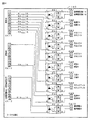
図11は、ターミナル基板160の内部構成を示す回路図である。図11に示すターミナル基板160において、左側上段のコネクタCN−1,CN−2は、主基板31からの信号を伝達するケーブルを接続するためのコネクタであり、左側下段のコネクタCN−3は、払出制御基板37からの信号を、主基板31を経由して伝達するケーブルを接続するためのコネクタである。また、右側のコネクタCN1〜CN10は、ホールコンピュータなど外部装置に対して信号を伝達するケーブルを接続するためのコネクタである。また、ターミナル基板160には、ドライバ回路としての半導体リレー(PhotoMOSリレー)PC1〜PC10が搭載されている。   FIG. 11 is a circuit diagram showing the internal configuration of the terminal board 160. In the terminal board 160 shown in FIG. 11, the upper left connectors CN-1 and CN-2 are cables for connecting cables for transmitting signals from the main board 31, and the lower left connector CN-3 is This is a connector for connecting a cable for transmitting a signal from the payout control board 37 via the main board 31. The right connectors CN1 to CN10 are connectors for connecting cables that transmit signals to an external device such as a hall computer. The terminal board 160 is mounted with semiconductor relays (PhotoMOS relays) PC1 to PC10 as driver circuits.

主基板31からのケーブルがコネクタCN−1,CN−2に接続されることにより、主基板31(遊技制御用マイクロコンピュータ560)から各種信号がターミナル基板160に入力される。具体的には、コネクタCN−1の端子「2」に図柄確定回数1信号が入力され、コネクタCN−1の端子「3」に始動口信号が入力され、コネクタCN−1の端子「4」に大当り1信号が入力され、コネクタCN−1の端子「5」に大当り2信号が入力され、コネクタCN−1の端子「6」に大当り3信号が入力され、コネクタCN−1の端子「7」に時短信号が入力され、コネクタCN−1の端子「8」に入賞信号が入力され、コネクタCN−1の端子「9」にセキュリティ信号が入力され、コネクタCN−2の端子「9」に高確中信号が入力される。   When the cable from the main board 31 is connected to the connectors CN-1 and CN-2, various signals are input from the main board 31 (game control microcomputer 560) to the terminal board 160. Specifically, the symbol determination number 1 signal is input to the terminal “2” of the connector CN-1, the start port signal is input to the terminal “3” of the connector CN-1, and the terminal “4” of the connector CN-1 is input. 1 signal is input to the terminal “5” of the connector CN-1, 2 signals are input to the terminal “6” of the connector CN-1, and 3 signals of the jackpot are input to the terminal “7” of the connector CN-1. To the terminal “8” of the connector CN-1, a winning signal is input to the terminal “9” of the connector CN-1, and a terminal “9” of the connector CN-2 is input. A high-accuracy signal is input.

また、払出制御基板37からのケーブルが主基板31を経由してコネクタCN−3に接続されることにより、払出制御基板37(払出制御用マイクロコンピュータ370)からの信号がターミナル基板160に入力される。具体的には、コネクタCN−3の端子「9」に賞球情報が入力される。   Further, when the cable from the payout control board 37 is connected to the connector CN-3 via the main board 31, a signal from the payout control board 37 (the payout control microcomputer 370) is input to the terminal board 160. The Specifically, the prize ball information is input to the terminal “9” of the connector CN-3.

図11に示すように、ターミナル基板160では、コネクタCN−1、コネクタCN−2およびコネクタCN−3の端子「1」に基準電位の信号線が接続され、その信号線が分岐して、各々の半導体リレーPC1〜PC10の入力端子「1」に接続されている。また、コネクタCN−1の端子「2」〜「9」、コネクタCN−2のコネクタ「9」、およびコネクタCN−3のコネクタ「9」に接続された信号線は、それぞれ、1KΩの抵抗R1〜R10を介して半導体リレーPC1〜PC10の入力端子「2」に接続されている。また、半導体リレーPC1〜PC10の出力端子「4」に接続された信号線は、それぞれ、コネクタCN1〜CN10の端子「1」に接続されている。また、半導体リレーPC1〜PC10の出力端子「3」に接続された信号線は、それぞれ、コネクタCN1〜CN10の端子「2」に接続されている。   As shown in FIG. 11, in the terminal board 160, the signal line of the reference potential is connected to the terminal “1” of the connector CN-1, the connector CN-2, and the connector CN-3, and the signal lines are branched. Are connected to the input terminal “1” of the semiconductor relays PC1 to PC10. The signal lines connected to the terminals “2” to “9” of the connector CN-1, the connector “9” of the connector CN-2, and the connector “9” of the connector CN-3 are each 1KΩ resistance R1. Are connected to the input terminal “2” of the semiconductor relays PC1 to PC10 via R10. The signal lines connected to the output terminals “4” of the semiconductor relays PC1 to PC10 are connected to the terminals “1” of the connectors CN1 to CN10, respectively. The signal lines connected to the output terminals “3” of the semiconductor relays PC1 to PC10 are connected to the terminals “2” of the connectors CN1 to CN10, respectively.

半導体リレーPC1〜PC10では、入力端子に信号電流が流れると、入力側の発光素子(LED)が発光する。発光された光は、LEDと対向に設けられた光電素子(太陽電池)に透明シリコンを通って照射される。光を受けた光電素子は、光の量に応じて電圧に交換し、この電圧は制御回路を通って出力部のMOSFETゲートを充電する。光電素子より供給されるMOSFETゲート電圧が設定電圧値に達すると、MOSFETが導通状態になり、負荷をオンさせる。入力端子の信号電流が切れると、発光素子(LED)の発光が止まる。LEDの発光が止まると、光電素子の電圧が下がり、光電素子から供給される電圧が下がると制御回路により、MOSFETのゲート負荷を急速に放電させる。この制御回路によりMOSFETが非導通状態になり、負荷をオフさせる。   In the semiconductor relays PC1 to PC10, when a signal current flows through the input terminal, the light emitting element (LED) on the input side emits light. The emitted light is applied to the photoelectric element (solar cell) provided opposite to the LED through the transparent silicon. The photoelectric element that has received the light is exchanged for voltage according to the amount of light, and this voltage passes through the control circuit to charge the MOSFET gate of the output section. When the MOSFET gate voltage supplied from the photoelectric element reaches the set voltage value, the MOSFET becomes conductive and turns on the load. When the signal current at the input terminal is cut off, the light emitting element (LED) stops emitting light. When the light emission of the LED stops, the voltage of the photoelectric element decreases, and when the voltage supplied from the photoelectric element decreases, the gate load of the MOSFET is rapidly discharged by the control circuit. With this control circuit, the MOSFET is turned off and the load is turned off.

以上のような半導体リレーPC1〜PC10の動作により、入力側のコネクタCN−1、コネクタCN−2およびコネクタCN−3から入力された信号が出力側のコネクタCN1〜CN10に伝達され、ホールコンピュータなど外部装置に対して出力される。具体的には、コネクタCN1から図柄確定回数1信号が出力され、コネクタCN2から始動口信号が出力され、コネクタCN3から大当り1信号が出力され、コネクタCN4から大当り2信号が出力され、コネクタCN5から大当り3信号が出力され、コネクタCN6から時短信号が出力され、コネクタCN7から入賞信号が出力され、コネクタCN8からセキュリティ信号が出力され、コネクタCN9から高確中信号が出力され、コネクタCN10から賞球情報が出力される。なお、ターミナル基板160における各外部出力信号に対するコネクタの割り当ては、この実施の形態で示したものに限られない。たとえば、セキュリティ信号については、ターミナル基板160に設けられた一番端のコネクタ(たとえば、コネクタCN10)から出力されるようにしてもよい。   By the operation of the semiconductor relays PC1 to PC10 as described above, signals input from the input side connector CN-1, connector CN-2, and connector CN-3 are transmitted to the output side connectors CN1 to CN10, and a hall computer or the like. Output to an external device. Specifically, the design CN count 1 signal is output from the connector CN1, the start signal is output from the connector CN2, the jackpot signal is output from the connector CN3, the jackpot signal is output from the connector CN4, and the connector CN5 is output. Three jackpot signals are output, a time signal is output from the connector CN6, a winning signal is output from the connector CN7, a security signal is output from the connector CN8, a high-probability medium signal is output from the connector CN9, and a prize is output from the connector CN10. Sphere information is output. It should be noted that the assignment of connectors to each external output signal on terminal board 160 is not limited to that shown in this embodiment. For example, the security signal may be output from the outermost connector (for example, connector CN10) provided on the terminal board 160.

なお、コネクタCN7から出力される入賞信号は、所定数分(この実施の形態では、10個分)の賞球を払い出すための所定の払出条件が成立したこと(始動入賞口14、大入賞口、普通入賞口29,30への入賞が発生したこと。賞球の払出までは行なわれていない。具体的には、近接スイッチ(入賞口スイッチ29a,30a、カウントスイッチ23、始動口スイッチ14a)からの検出信号とフォトセンサ(入賞確認スイッチ29b,30b,23b,14b)からの検出信号との両方を入力したことを条件として、所定の払出条件が成立したと判定されたこと。)を示す信号である。入賞信号を確認することによって、払い出される賞球数の予定数を、ホールコンピュータなどの外部装置側で認識できるようにすることができる。   The winning signal output from the connector CN7 indicates that a predetermined payout condition for paying out a predetermined number (in this embodiment, 10 balls) of winning balls is satisfied (start winning port 14, large winning prize). The winnings are made to the mouths and the normal winning holes 29 and 30. The prize balls are not paid out. Specifically, the proximity switches (the winning hole switches 29a and 30a, the count switch 23, the start opening switch 14a). ) And a detection signal from the photo sensor (the winning confirmation switches 29b, 30b, 23b, 14b) are input, and it is determined that a predetermined payout condition has been established). It is a signal to show. By confirming the winning signal, the expected number of prize balls to be paid out can be recognized by an external device such as a hall computer.

また、コネクタCN10から出力される賞球情報は、特定数(この実施の形態では、10個)の賞球が払い出されたこと(球払出装置97が駆動されて実際に賞球が払い出されたこと)を示す信号である。賞球情報を確認することによって、実際に払い出された賞球数を、ホールコンピュータなどの外部装置側で認識できるようにすることができる。また、入賞信号で示される賞球の予定数と賞球情報で示される払出済みの賞球数とを確認することによって、賞球払出が正常に行なわれたか否かや賞球過不足数を、ホールコンピュータなどの外部装置側で認識できるようにすることができる。   Also, the prize ball information output from the connector CN10 is that a specific number (10 balls in this embodiment) of prize balls has been paid out (the ball payout device 97 is driven and the prize balls are actually paid out). This is a signal indicating that By confirming the prize ball information, the number of prize balls actually paid out can be recognized by an external device such as a hall computer. Also, by confirming the planned number of prize balls indicated by the winning signal and the number of prize balls already paid out indicated by the prize ball information, whether or not the prize balls have been paid out normally and the number of excess or insufficient prize balls are determined. It can be recognized by an external device such as a hall computer.

また、コネクタCN8から出力されるセキュリティ信号は、遊技機のセキュリティ状態を示す信号である。具体的には、後述するように、始動口スイッチ14aの検出結果と入賞確認スイッチ14bの検出結果とに基づいて、始動入賞口14への排出異常が発生したと判定された場合に、セキュリティ信号がホールコンピュータなどの外部装置に出力される。また、カウントスイッチ23の検出結果と入賞確認スイッチ23bの検出結果とに基づいて、大入賞口への排出異常が発生したと判定された場合に、セキュリティ信号がホールコンピュータなどの外部装置に出力される。そのように構成することによって、電波などを用いて始動入賞口14や大入賞口への入賞数が実際の入賞数よりも多くなるように認識させるような不正行為が行なわれたことを、ホールコンピュータなどの外部装置側で認識できるようにすることができる。   The security signal output from the connector CN8 is a signal indicating the security state of the gaming machine. Specifically, as will be described later, when it is determined that an abnormality in discharging to the start winning port 14 has occurred based on the detection result of the start port switch 14a and the detection result of the winning confirmation switch 14b, the security signal Is output to an external device such as a hall computer. In addition, when it is determined that an abnormal discharge to the big prize opening has occurred based on the detection result of the count switch 23 and the detection result of the winning confirmation switch 23b, a security signal is output to an external device such as a hall computer. The By configuring in this way, it is possible to confirm that an illegal act that caused the player to recognize that the number of winnings at the start winning opening 14 or the big winning opening is larger than the actual winning number using radio waves or the like is performed. It can be recognized by an external device such as a computer.

この実施の形態では、排出異常の発生に基づきセキュリティ信号を外部出力する場合には、遊技機への電源が再投入され初期化処理が実行されるまで、この排出異常の発生に基づくセキュリティ信号の外部出力が継続される。なお、後述するように、初期化処理が行なわれた場合にはセキュリティ信号が所定期間(たとえば、30秒間)外部出力されるので、より正確には、遊技機への電源が再投入され初期化処理が実行されたときに、内部的には排出異常の発生に基づくセキュリティ信号の外部出力を終了し、初期化処理に基づくセキュリティ信号の外部出力が開始され、所定期間(たとえば、30秒間)を経過するまでセキュリティ信号の出力が継続される。従って、見た目上は、排出異常の発生に基づきセキュリティ信号の外部出力が開始された場合には、遊技機への電源が再投入され初期化処理が実行された後、所定期間(たとえば、30秒間)を経過したときにセキュリティ信号の外部出力が終了する。   In this embodiment, when the security signal is output externally based on the occurrence of the discharge abnormality, the security signal based on the occurrence of the discharge abnormality is not replayed until the gaming machine is turned on again and the initialization process is executed. External output continues. As will be described later, when the initialization process is performed, the security signal is externally output for a predetermined period (for example, 30 seconds), so more accurately, the power to the gaming machine is turned on again and the initialization is performed. When the process is executed, the external output of the security signal based on the occurrence of the discharge abnormality is terminated internally, and the external output of the security signal based on the initialization process is started, and a predetermined period (for example, 30 seconds) The security signal continues to be output until the time has elapsed. Therefore, apparently, when external output of a security signal is started based on the occurrence of a discharge abnormality, power is reapplied to the gaming machine and initialization processing is performed, and then a predetermined period (for example, 30 seconds). ), The security signal external output ends.

また、この実施の形態では、可変入賞球装置15が開状態でないときに始動入賞口14への遊技球の入賞を検出した場合や、大当り遊技中でないときに大入賞口への遊技球の入賞を検出した場合に異常入賞が発生したと判定され、この異常入賞が検出された場合にも、セキュリティ信号が所定期間(たとえば、30秒間)ホールコンピュータなどの外部装置に出力される。そのように構成することによって、可変入賞球装置15や大入賞口に対する不正行為によって異常入賞が生じたことを報知することができ、その結果、可変入賞球装置15や大入賞口に対する不正行為を確実に防止することができる。   Further, in this embodiment, when a winning of the game ball to the start winning port 14 is detected when the variable winning ball device 15 is not in the open state, or when the game ball is won to the big winning port when the big hit game is not being played. It is determined that an abnormal winning has occurred, and when this abnormal winning is detected, a security signal is output to an external device such as a hall computer for a predetermined period (for example, 30 seconds). With such a configuration, it is possible to notify that an abnormal winning has occurred due to an illegal act with respect to the variable winning ball device 15 or the grand prize opening. It can be surely prevented.

また、この実施の形態では、遊技機への電源投入が行なわれて初期化処理が実行された場合にも、セキュリティ信号が所定期間(たとえば、30秒間)ホールコンピュータなどの外部装置に出力される。そのように構成することによって、不自然なタイミングで(たとえば、遊技店の開店時に全ての遊技機の電源リセット作業を終えた後であるにもかかわらず)初期化処理が実行されたことを認識可能とすることによって、不正に遊技機を電源リセットさせて電源リセットのタイミングで大当りを狙うような不正行為が行なわれた可能性を、ホールコンピュータなどの外部装置側で認識できるようにすることができる。   In this embodiment, even when the gaming machine is turned on and the initialization process is executed, a security signal is output to an external device such as a hall computer for a predetermined period (for example, 30 seconds). . By configuring as such, it is recognized that the initialization process has been executed at an unnatural timing (for example, even after all the gaming machine power reset operations have been completed when the amusement store is opened). By enabling it, it is possible to recognize on the external device side such as a hall computer the possibility of fraudulent acts that illegally reset the power of the gaming machine and aim for a big hit at the power reset timing it can.

なお、この実施の形態では、上記のように、排出異常が検出された場合と、異常入賞が検出された場合と、初期化処理(たとえば、遊技機への電源投入時に、クリアスイッチによる操作が行なわれたことに基づいてRAM55の記憶内容をクリアするなどの処理)が実行された場合とで、共通のセキュリティ信号をターミナル基板160の共通のコネクタCN8から外部出力している。これは、初期化処理が実行されるのは、通常、遊技店の開店時に遊技機の電源リセット作業を行なう場合のみであることから、1日のうち1回程度しか出力されない信号のためにターミナル基板160上に専用のコネクタや半導体リレーを設けることは効率的ではなく無駄が多い。また、排出異常や異常入賞も何らかの不正行為が行なわれない限り発生しないのであるから、排出異常や異常入賞のために専用のコネクタや半導体リレーを個別に設けることも効率的ではなく無駄が多い。そこで、この実施の形態では、排出異常が検出された場合と、異常入賞が検出された場合と、初期化処理が実行された場合とで、共通のコネクタCN8からセキュリティ信号を出力するように構成することによって、外部出力用の信号線や回路素子の無駄を低減している。すなわち、ホールコンピュータなどの外部装置に情報を出力するための機構の部品数の増加や配線作業の複雑化を防ぐことができる。   In this embodiment, as described above, when a discharge abnormality is detected, when an abnormal winning is detected, and when an initialization process (for example, when the power to the gaming machine is turned on, an operation by a clear switch is performed). A common security signal is externally output from the common connector CN8 of the terminal board 160 when a process such as clearing the stored contents of the RAM 55 is executed based on what has been done. This is because the initialization process is usually performed only when the game machine power is reset when the amusement store is opened. Therefore, the terminal is used for a signal that is output only once a day. Providing a dedicated connector or semiconductor relay on the substrate 160 is not efficient and wasteful. In addition, since abnormal discharge and abnormal winnings do not occur unless some sort of fraud is performed, it is not efficient and wasteful to separately provide a dedicated connector or semiconductor relay for abnormal discharging or abnormal winnings. Therefore, in this embodiment, the configuration is such that a security signal is output from the common connector CN8 when a discharge abnormality is detected, when an abnormal winning is detected, and when an initialization process is executed. By doing so, waste of signal lines and circuit elements for external output is reduced. That is, it is possible to prevent an increase in the number of parts of a mechanism for outputting information to an external device such as a hall computer and complication of wiring work.

なお、セキュリティ信号として共通のコネクタから外部出力される信号は、この実施の形態で示したものに限られない。たとえば、始動入賞口14や大入賞口への排出異常に限らず、普通入賞口29,30への排出異常も検出して、ターミナル基板160の共通のコネクタCN8からセキュリティ信号として外部出力可能なように構成してもよい。この場合、たとえば、普通入賞口29,30についても、始動入賞口14や大入賞口と同様に、遊技球の入賞を検出するためのスイッチとして検出方式の異なる2種類のスイッチ(近接スイッチとフォトセンサ)を用いて、始動入賞口14や大入賞口と同様の判定方法に従って、排出異常の有無を判定するようにすればよい。また、たとえば、始動入賞口14と大入賞口とのいずれか一方の排出異常のみを検出して、セキュリティ信号を外部出力するように構成してもよい。   The signal output from the common connector as the security signal is not limited to that shown in this embodiment. For example, not only abnormal discharge to the start winning port 14 or the grand prize winning port, but also abnormal discharge to the normal winning ports 29 and 30 can be detected and externally output as a security signal from the common connector CN8 of the terminal board 160. You may comprise. In this case, for example, the normal winning holes 29 and 30 also have two types of switches (proximity switch and photo) as detection switches for detecting the winning of a game ball, similarly to the start winning hole 14 and the big winning hole. The presence / absence of the discharge abnormality may be determined using a sensor) according to the same determination method as that for the start winning opening 14 and the big winning opening. Further, for example, it may be configured to detect only the discharge abnormality of one of the start winning port 14 and the big winning port and output the security signal to the outside.

また、たとえば、この実施の形態では、始動入賞口14および大入賞口の両方の異常入賞を検出してセキュリティ信号を外部出力可能に構成しているが、始動入賞口14と大入賞口とのいずれか一方の異常入賞のみを検出して、セキュリティ信号を外部出力するように構成してもよい。   Further, for example, in this embodiment, the abnormal winnings of both the start winning port 14 and the big winning port are detected and the security signal can be output to the outside, but the start winning port 14 and the big winning port Only one of the abnormal winnings may be detected and a security signal may be output to the outside.

また、たとえば、遊技機に設けられた磁石センサ43で異常磁気を検出した場合や、遊技機に設けられた電波センサ42で異常電波を検出した場合に、ターミナル基板160の共通のコネクタCN8からセキュリティ信号として外部出力可能なように構成してもよい。また、たとえば、遊技機に設けられた各種スイッチの異常を検出した場合(たとえば、入力値が閾値を超えたと判定したことにより、短絡などの発生を検出した場合)に、ターミナル基板160の共通のコネクタCN8からセキュリティ信号として外部出力可能なように構成してもよい。   Further, for example, when abnormal magnetism is detected by the magnet sensor 43 provided in the gaming machine or when abnormal radio waves are detected by the radio wave sensor 42 provided in the gaming machine, the security is detected from the common connector CN8 of the terminal board 160. You may comprise so that external output is possible as a signal. Further, for example, when an abnormality of various switches provided in the gaming machine is detected (for example, when occurrence of a short circuit is detected by determining that the input value exceeds the threshold value), a common terminal board 160 is used. The connector CN8 may be configured so that it can be externally output as a security signal.

上記のように、普通入賞口29,30への排出異常や磁気異常、電波異常についてもターミナル基板160の共通のコネクタCN8からセキュリティ信号として外部出力可能なように構成すれば、1本の信号線さえ接続すればホールコンピュータなど外部装置で異常検出を行なえるようにすることができ、異常検出に関する作業負担を軽減することができる。   As described above, one signal line can be provided if an abnormality such as abnormal discharge to the normal winning holes 29 and 30, magnetic abnormality, and radio wave abnormality can be output externally as a security signal from the common connector CN 8 of the terminal board 160. As long as it is connected, an abnormality can be detected by an external device such as a hall computer, and the work load related to the abnormality detection can be reduced.

また、たとえば、遊技制御用マイクロコンピュータ560と払出制御用マイクロコンピュータ370との間の通信異常を検出した場合にも、ターミナル基板160の共通のコネクタCN8からセキュリティ信号として外部出力可能なように構成してもよい。本実施の形態では、たとえば、遊技制御用マイクロコンピュータ560は、払出制御用マイクロコンピュータ370から払出制御コマンドを受信できなかったことに基づいて通信異常が発生したと判定する。このとき、ターミナル基板160の共通のコネクタCN8からセキュリティ信号として外部出力してもよい。また、たとえば、遊技制御用マイクロコンピュータ560は、シリアル通信回路511のステータスレジスタ(図示せず)のいずれかのエラービットの値がセットされていることに基づいて通信異常が発生したと判定し、ターミナル基板160の共通のコネクタCN8からセキュリティ信号として外部出力してもよい。   Further, for example, even when a communication abnormality between the game control microcomputer 560 and the payout control microcomputer 370 is detected, it is configured so that it can be externally output as a security signal from the common connector CN8 of the terminal board 160. May be. In the present embodiment, for example, the game control microcomputer 560 determines that a communication abnormality has occurred based on the failure to receive a payout control command from the payout control microcomputer 370. At this time, the security signal may be externally output from the common connector CN8 of the terminal board 160. Further, for example, the game control microcomputer 560 determines that a communication abnormality has occurred based on the value of any error bit in the status register (not shown) of the serial communication circuit 511 being set, The security signal may be externally output from the common connector CN8 of the terminal board 160.

なお、セキュリティ信号用の信号線およびコネクタCN8とは別に、遊技制御用マイクロコンピュータ560と払出制御用マイクロコンピュータ370との間の通信異常専用の信号線およびコネクタをターミナル基板160に設けてもよい。そして、遊技制御用マイクロコンピュータ560と払出制御用マイクロコンピュータ370との間の通信異常を検出した場合には、セキュリティ信号とは別の信号として、ターミナル基板160を経由してホールコンピュータなどの外部装置に出力するようにしてもよい。   In addition to the signal line and connector CN8 for the security signal, a signal line and connector dedicated to communication abnormality between the game control microcomputer 560 and the payout control microcomputer 370 may be provided on the terminal board 160. When a communication abnormality between the game control microcomputer 560 and the payout control microcomputer 370 is detected, an external device such as a hall computer is transmitted via the terminal board 160 as a signal different from the security signal. May be output.

また、セキュリティ信号出力用の信号線とは別に、初期化処理実行の検出や、始動入賞口14の排出異常の検出、大入賞口の排出異常の検出、始動入賞口14への異常入賞の検出、大入賞口への異常入賞の検出、磁気異常の検出、電波異常の検出、通信異常の検出について、それぞれ別々の信号線を設けるようにし、ターミナル基板160から、セキュリティ信号とともに、それぞれの異常に対応した外部出力信号も、ホールコンピュータなどの外部装置に出力するようにしてもよい。そのように構成すれば、セキュリティ信号を確認することによって何らかの異常が発生していることを認識できるとともに、さらに異常の種類ごとに出力される信号を確認することによって遊技店側で異常の種類を確認することができる。従って、遊技店側から異常の種類の確認まで要求されているような場合には、セキュリティ信号とは別に異常種類ごとの外部出力信号を設けることによって、より遊技店のニーズに応えた外部出力を行なえるようにすることができる。一方で、何らかの異常が発生していることの確認のみを要求しているような遊技店の場合には、外部出力される信号のうち、セキュリティ信号のみをホールコンピュータなどの外部装置に接続して確認するようにすればよい。   In addition to the signal line for security signal output, detection of initialization processing, detection of abnormal discharge of the start winning port 14, detection of abnormal discharge of the big winning port, detection of abnormal winning to the start winning port 14 In addition, a separate signal line is provided for each of the abnormal winning prize detection, the magnetic abnormality detection, the radio wave abnormality detection, and the communication abnormality detection in the grand prize opening. A corresponding external output signal may also be output to an external device such as a hall computer. With such a configuration, it is possible to recognize that some abnormality has occurred by checking the security signal, and further, by checking the signal output for each type of abnormality, the amusement store can determine the type of abnormality. Can be confirmed. Therefore, when there is a request from the amusement store to confirm the type of abnormality, an external output signal for each abnormality type is provided separately from the security signal, so that an external output that better meets the needs of the amusement store can be provided. Can be done. On the other hand, in the case of a game shop that only requires confirmation that some kind of abnormality has occurred, only the security signal out of the externally output signals is connected to an external device such as a hall computer. Check it.

上記のように、半導体リレーPC1〜PC10をターミナル基板160に設けたことにより、外部から遊技機内部への信号入力を防止することができ、その結果、不正行為を確実に防止することができる。なお、上記の例では、ターミナル基板160に半導体リレーPC1〜PC10を設けていたが、半導体リレーPC1〜PC10ではなく、機械式のリレー等の他のリレー素子であってもよい。   As described above, by providing the semiconductor relays PC1 to PC10 on the terminal board 160, signal input from the outside to the inside of the gaming machine can be prevented, and as a result, illegal acts can be reliably prevented. In the above example, the semiconductor relays PC1 to PC10 are provided on the terminal board 160. However, other relay elements such as a mechanical relay may be used instead of the semiconductor relays PC1 to PC10.

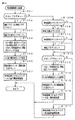
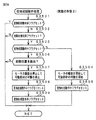
次に遊技機の動作について説明する。図12は、遊技機に対して電力供給が開始され遊技制御用マイクロコンピュータ560へのリセット信号がハイレベルになったことに応じて遊技制御用マイクロコンピュータ560のCPU56が実行するメイン処理を示すフローチャートである。リセット信号が入力されるリセット端子の入力レベルがハイレベルになると、遊技制御用マイクロコンピュータ560のCPU56は、ROM54に記憶されているセキュリティチェックプログラム54Aに従って、プログラムの内容が正当か否かを確認するための処理であるセキュリティチェック処理を実行した後、S1以降のメイン処理を開始する。メイン処理において、CPU56は、まず、必要な初期設定を行なう。   Next, the operation of the gaming machine will be described. FIG. 12 is a flowchart showing a main process executed by the CPU 56 of the game control microcomputer 560 in response to the start of power supply to the game machine and the reset signal to the game control microcomputer 560 becoming high level. It is. When the input level of the reset terminal to which the reset signal is input becomes high level, the CPU 56 of the game control microcomputer 560 confirms whether the contents of the program are valid according to the security check program 54A stored in the ROM 54. After executing the security check process, which is a process for this, the main process after S1 is started. In the main process, the CPU 56 first performs necessary initial settings.

初期設定処理において、CPU56は、まず、割込禁止に設定する(S1)。次に、マスク可能割込の割込モードを設定し(S2)、スタックポインタにスタックポインタ指定アドレスを設定する(S3)。なお、S2では、遊技制御用マイクロコンピュータ560の特定レジスタ(Iレジスタ)の値(1バイト)と内蔵デバイスが出力する割込ベクタ(1バイト:最下位ビット0)から合成されるアドレスが、割込番地を示すモードに設定する。また、マスク可能な割込が発生すると、CPU56は、自動的に割込禁止状態に設定するとともに、プログラムカウンタの内容をスタックにセーブする。   In the initial setting process, the CPU 56 first sets the interrupt prohibition (S1). Next, an interrupt mode for maskable interrupts is set (S2), and a stack pointer designation address is set in the stack pointer (S3). In S2, an address synthesized from the value (1 byte) of the specific register (I register) of the game control microcomputer 560 and the interrupt vector (1 byte: least significant bit 0) output from the built-in device is Set to the mode that indicates the included address. When a maskable interrupt occurs, the CPU 56 automatically sets the interrupt disabled state and saves the contents of the program counter in the stack.

次いで、CPU56は、払出制御用マイクロコンピュータ370に対して、接続信号の出力を開始する(S4)。なお、CPU56は、S4で接続信号の出力を開始すると、遊技機の電源供給が停止したり、何らかの通信異常が生じて出力不能とならない限り、払出制御用マイクロコンピュータ370に対して接続信号を継続して出力する。   Next, the CPU 56 starts outputting a connection signal to the payout control microcomputer 370 (S4). When the CPU 56 starts outputting the connection signal in S4, the CPU 56 continues to output the connection signal to the payout control microcomputer 370 unless the power supply of the gaming machine is stopped or the output becomes impossible due to some communication abnormality. And output.

次いで、内蔵デバイスレジスタの設定(初期化)を行なう(S5)。S5の処理によって、内蔵デバイス(内蔵周辺回路)であるCTC(カウンタ/タイマ)およびPIO(パラレル入出力ポート)の設定(初期化)がなされる。   Next, the built-in device register is set (initialized) (S5). By the processing of S5, the CTC (counter / timer) and PIO (parallel input / output port), which are built-in devices (built-in peripheral circuits), are set (initialized).

この実施の形態で用いられる遊技制御用マイクロコンピュータ560は、I/Oポート(PIO)およびタイマ/カウンタ回路(CTC)504も内蔵している。   The game control microcomputer 560 used in this embodiment also incorporates an I / O port (PIO) and a timer / counter circuit (CTC) 504.

次いで、CPU56は、RAM55をアクセス可能状態に設定し(S6)、クリア信号のチェック処理に移行する。   Next, the CPU 56 sets the RAM 55 in an accessible state (S6), and proceeds to a clear signal check process.

なお、遊技の進行を制御する遊技装置制御処理(遊技制御処理)の開始タイミングをソフトウェアで遅らせるためのソフトウェア遅延処理を実行するようにしてもよい。そのようなソフトウェア遅延処理によって、ソフトウェア遅延処理を実行しない場合に比べて、遊技制御処理の開始タイミングを遅延させることができる。遅延処理を実行したときには、他の制御基板(たとえば、払出制御基板37)に対して、遊技制御基板(主基板31)が送信するコマンドを他の制御基板のマイクロコンピュータが受信できないという状況が発生することを防止できる。   Note that a software delay process for delaying the start timing of the game device control process (game control process) for controlling the progress of the game by software may be executed. By such software delay processing, the start timing of the game control processing can be delayed as compared with the case where the software delay processing is not executed. When the delay process is executed, a situation occurs in which the microcomputer of the other control board cannot receive the command transmitted from the game control board (main board 31) to the other control board (for example, the payout control board 37). Can be prevented.

次いで、CPU56は、クリアスイッチがオンされているか否か確認する(S7)。なお、CPU56は、入力ポート0を介して1回だけクリア信号の状態を確認するようにしてもよいが、複数回クリア信号の状態を確認するようにしてもよい。たとえば、クリア信号の状態がオフ状態であることを確認したら、所定時間(たとえば、0.1秒)の遅延時間をおいた後、クリア信号の状態を再確認する。そのときにクリア信号の状態がオン状態であることを確認したら、クリア信号がオン状態になっていると判定する。また、このときにクリア信号の状態がオフ状態であることを確認したら、所定時間の遅延時間をおいた後、再度、クリア信号の状態を再確認するようにしてもよい。ここで、再確認の回数は、1回または2回に限られず、3回以上であってもよい。また、2回チェックして、チェック結果が一致していなかったときにもう一度確認するようにしてもよい。   Next, the CPU 56 checks whether or not the clear switch is turned on (S7). Note that the CPU 56 may confirm the state of the clear signal only once via the input port 0, but may confirm the state of the clear signal a plurality of times. For example, if it is confirmed that the state of the clear signal is OFF, a delay time of a predetermined time (for example, 0.1 seconds) is set, and then the state of the clear signal is reconfirmed. If it is confirmed that the clear signal is in the on state at that time, it is determined that the clear signal is in the on state. Further, at this time, if it is confirmed that the state of the clear signal is the off state, after a delay time of a predetermined time, the state of the clear signal may be confirmed again. Here, the number of reconfirmations is not limited to once or twice, but may be three or more times. It is also possible to check twice and check again when the check results do not match.

S7でクリアスイッチがオンでない場合には、遊技機への電力供給が停止したときにバックアップRAM領域のデータ保護処理(たとえばパリティデータの付加等の電力供給停止時処理)が行なわれたか否か確認する(S8)。この実施の形態では、電力供給の停止が生じた場合には、バックアップRAM領域のデータを保護するための処理が行なわれている。そのような電力供給停止時処理が行なわれていたことを確認した場合には、CPU56は、電力供給停止時処理が行なわれた、すなわち電力供給停止時の制御状態が保存されていると判定する。電力供給停止時処理が行なわれていないことを確認した場合には、CPU56は初期化処理を実行する。   If the clear switch is not on in S7, check whether data protection processing of the backup RAM area (for example, power supply stop processing such as addition of parity data) has been performed when power supply to the gaming machine is stopped (S8). In this embodiment, when power supply is stopped, processing for protecting data in the backup RAM area is performed. When it is confirmed that such power supply stop processing has been performed, the CPU 56 determines that the power supply stop processing has been performed, that is, the control state at the time of power supply stop is stored. . When it is confirmed that the power supply stop process is not performed, the CPU 56 executes an initialization process.

電力供給停止時処理が行なわれていたか否かは、電力供給停止時処理においてバックアップRAM領域に保存されるバックアップ監視タイマの値が、電力供給停止時処理を実行したことに応じた値(たとえば2)になっているか否かによって確認される。なお、そのような確認の仕方は一例であって、たとえば、電力供給停止時処理においてバックアップフラグ領域に電力供給停止時処理を実行したことを示すフラグをセットし、S8において、そのフラグがセットされていることを確認したら電力供給停止時処理が行なわれたと判定してもよい。   Whether or not the power supply stop process has been performed is determined based on the value of the backup monitoring timer stored in the backup RAM area in the power supply stop process depending on the execution of the power supply stop process (for example, 2). ) Is confirmed by whether or not. Note that such a confirmation method is merely an example. For example, a flag indicating that the power supply stop process has been executed is set in the backup flag area in the power supply stop process, and the flag is set in S8. If it is confirmed that the power supply is stopped, it may be determined that the power supply stop process has been performed.

電力供給停止時の制御状態が保存されていると判定したら、CPU56は、バックアップRAM領域のデータチェック(この例ではパリティチェック)を行なう(S9)。この実施の形態では、クリアデータ(00)をチェックサムデータエリアにセットし、チェックサム算出開始アドレスをポインタにセットする。また、チェックサムの対象になるデータ数に対応するチェックサム算出回数をセットする。そして、チェックサムデータエリアの内容とポインタが指すRAM領域の内容との排他的論理和を演算する。演算結果をチェックサムデータエリアにストアするとともに、ポインタの値を1増やし、チェックサム算出回数の値を1減算する。以上の処理が、チェックサム算出回数の値が0になるまで繰り返される。チェックサム算出回数の値が0になったら、CPU56は、チェックサムデータエリアの内容の各ビットの値を反転し、反転後のデータをチェックサムにする。   If it is determined that the control state at the time of stopping power supply is stored, the CPU 56 performs data check (parity check in this example) in the backup RAM area (S9). In this embodiment, clear data (00) is set in the checksum data area, and the checksum calculation start address is set in the pointer. Also, the number of checksum calculations corresponding to the number of data to be checksum is set. Then, the exclusive OR of the contents of the checksum data area and the contents of the RAM area pointed to by the pointer is calculated. The calculation result is stored in the checksum data area, the pointer value is incremented by 1, and the checksum calculation count value is decremented by 1. The above processing is repeated until the value of the checksum calculation count becomes zero. When the value of the checksum calculation count becomes 0, the CPU 56 inverts the value of each bit of the contents of the checksum data area and uses the inverted data as the checksum.

電力供給停止時処理において、上記の処理と同様の処理によってチェックサムが算出され、チェックサムはバックアップRAM領域に保存されている。S9では、算出したチェックサムと保存されているチェックサムとを比較する。不測の停電等の電力供給停止が生じた後に復旧した場合には、バックアップRAM領域のデータは保存されているはずであるから、チェック結果(比較結果)は正常(一致)になる。チェック結果が正常でないということは、バックアップRAM領域のデータが、電力供給停止時のデータとは異なっている可能性があることを意味する。そのような場合には、内部状態を電力供給停止時の状態に戻すことができないので、電力供給の停止からの復旧時でない電源投入時に実行される初期化処理(S10〜S14の処理)を実行する。   In the power supply stop process, a checksum is calculated by the same process as described above, and the checksum is stored in the backup RAM area. In S9, the calculated checksum is compared with the stored checksum. When the power supply is stopped after an unexpected power failure or the like, the data in the backup RAM area should be saved, so the check result (comparison result) is normal (matched). That the check result is not normal means that the data in the backup RAM area may be different from the data when the power supply is stopped. In such a case, since the internal state cannot be returned to the state when the power supply is stopped, the initialization process (the process of S10 to S14) that is executed when the power is turned on but not when the power supply is stopped is executed. To do.

チェック結果が正常であれば、CPU56は、バックアップ電源されたRAM55が記憶するデータを用いて遊技を再開するためのホットスタート処理を行なう(S91)。また、CPU56は、ROM54に格納されているバックアップ時コマンド送信テーブルの先頭アドレスをポインタに設定し(S92)、S15に移行する。なお、S92で設定された後、後述するS15aのシリアル通信回路設定処理が行なわれてからバックアップコマンドが送信されることになる。   If the check result is normal, the CPU 56 performs a hot start process for resuming the game using the data stored in the RAM 55 that is backed up (S91). Further, the CPU 56 sets the head address of the backup command transmission table stored in the ROM 54 as a pointer (S92), and proceeds to S15. After setting in S92, a backup command is transmitted after a serial communication circuit setting process in S15a described later is performed.

初期化処理では、CPU56は、まず、RAMクリア処理を行なう(S10)。なお、RAM55の全領域を初期化せず、所定のデータをそのままにしてもよい。また、ROM54に格納されている初期化時設定テーブルの先頭アドレスをポインタに設定し(S11)、初期化時設定テーブルの内容を順次業領域に設定する(S12)。   In the initialization process, the CPU 56 first performs a RAM clear process (S10). Note that the predetermined data may be left as it is without initializing the entire area of the RAM 55. Further, the start address of the initialization setting table stored in the ROM 54 is set as a pointer (S11), and the contents of the initialization setting table are sequentially set in the work area (S12).

S11およびS12の処理によって、たとえば、普通図柄判定用乱数カウンタ、普通図柄判定用バッファ、特別図柄バッファ、特別図柄プロセスフラグ、賞球中フラグ、球切れフラグ、排出異常フラグなど制御状態に応じて選択的に処理を行なうためのフラグに初期値が設定される。また、後述する各外部出力信号を出力するために用いる各タイマ(始動口情報記憶タイマや、入賞情報記憶タイマ、セキュリティ信号情報タイマなど)にも初期値(クリアデータ)が設定される。   By the processing of S11 and S12, for example, a normal symbol determination random number counter, a normal symbol determination buffer, a special symbol buffer, a special symbol process flag, a winning ball flag, a ball out flag, a discharge abnormality flag, etc. are selected according to the control state. An initial value is set in a flag for performing processing automatically. An initial value (clear data) is also set in each timer (start port information storage timer, winning information storage timer, security signal information timer, etc.) used to output each external output signal described later.

また、CPU56は、ROM54に格納されている初期化時コマンド送信テーブルの先頭アドレスをポインタに設定し(S13)、その内容に従ってサブ基板を初期化するための初期化コマンドをサブ基板に送信する処理を実行する(S14)。初期化コマンドとして、演出表示装置9に表示される初期図柄を示すコマンドや払出制御基板37への初期化コマンド等を使用することができる。なお、S13で設定された後、後述するS15aのシリアル通信回路設定処理が行なわれてから初期化コマンドが送信されることになる。   Further, the CPU 56 sets the start address of the initialization command transmission table stored in the ROM 54 as a pointer (S13), and transmits an initialization command for initializing the sub board according to the contents to the sub board. Is executed (S14). As an initialization command, a command indicating an initial symbol displayed on the effect display device 9, an initialization command to the payout control board 37, or the like can be used. After setting in S13, an initialization command is transmitted after serial communication circuit setting processing in S15a described later is performed.

また、CPU56は、セキュリティ信号情報タイマに所定時間(本例では、30秒)をセットする(S14a)。セキュリティ信号情報タイマは、ターミナル基板160から出力するセキュリティ信号のオン時間を計測するためのタイマである。この実施の形態では、S14aでセキュリティ信号情報タイマに所定時間がセットされたことに基づいて、後述する情報出力処理(S31参照)が実行されることによって、遊技機の電源投入時に初期化処理が実行されたときに、セキュリティ信号が所定時間(本例では、30秒)外部出力される。   The CPU 56 sets a predetermined time (in this example, 30 seconds) in the security signal information timer (S14a). The security signal information timer is a timer for measuring the ON time of the security signal output from the terminal board 160. In this embodiment, an initialization process is performed when the gaming machine is turned on by executing an information output process (see S31) described later based on the fact that a predetermined time is set in the security signal information timer in S14a. When executed, a security signal is externally output for a predetermined time (in this example, 30 seconds).

また、CPU56は、乱数回路509を初期設定する乱数回路設定処理を実行する(S15)。この場合、CPU56は、あらかじめROM54に格納されている乱数回路設定プログラムに従って処理を実行することによって、乱数回路509にランダムRの値を更新させるための設定を行なう。   Further, the CPU 56 executes a random number circuit setting process for initially setting the random number circuit 509 (S15). In this case, the CPU 56 performs processing according to the random number circuit setting program stored in the ROM 54 in advance, thereby setting the random number circuit 509 to update the random R value.

また、CPU56は、シリアル通信回路511を初期設定するシリアル通信回路設定処理を実行する(S15a)。この場合、CPU56は、シリアル通信回路設定プログラムに従ってROM54の所定領域に格納されているデータをシリアル通信回路511に設定することによって、シリアル通信回路511に払出制御用マイクロコンピュータとシリアル通信させるための設定を行なう。   Further, the CPU 56 executes a serial communication circuit setting process for initial setting of the serial communication circuit 511 (S15a). In this case, the CPU 56 sets the data stored in the predetermined area of the ROM 54 in the serial communication circuit 511 in accordance with the serial communication circuit setting program, so that the serial communication circuit 511 performs serial communication with the payout control microcomputer. To do.

シリアル通信回路511を初期設定すると、CPU56は、シリアル通信回路511の割り込み要求に応じて実行する割込処理の優先順位を初期設定する(S15b)。この場合、CPU56は、割込優先順位設定プログラム557に従って処理を実行することによって、割込処理の優先順位を初期設定する。   When the serial communication circuit 511 is initialized, the CPU 56 initializes the priority of interrupt processing to be executed in response to the interrupt request from the serial communication circuit 511 (S15b). In this case, the CPU 56 initializes the priority of the interrupt process by executing the process according to the interrupt priority setting program 557.

たとえば、CPU56は、各割込処理のデフォルトの優先順位を含む所定の割込処理優先順位テーブルに従って、各割込処理の優先順位を初期設定する。この実施の形態では、CPU56は、割込処理優先順位テーブルに従って、シリアル通信回路511において通信異常が発生したことを割込原因とする割込処理を優先して実行するように初期設定する。この場合、たとえば、CPU56は、通信異常が発生したことを割込原因とする割込処理を優先して実行する旨を示す通信異常時割込優先実行フラグをセットする。   For example, the CPU 56 initializes the priority of each interrupt process according to a predetermined interrupt process priority table including the default priority of each interrupt process. In this embodiment, the CPU 56 performs initialization according to the interrupt processing priority table so as to preferentially execute an interrupt process that causes an interrupt to occur in the serial communication circuit 511. In this case, for example, the CPU 56 sets a communication error interrupt priority execution flag indicating that priority is given to interrupt processing whose cause is the occurrence of a communication error.

なお、この実施の形態では、タイマ割込とシリアル通信回路511からの割り込み要求とが同時に発生した場合、CPU56は、タイマ割込による割込処理を優先して行なう。   In this embodiment, when a timer interrupt and an interrupt request from the serial communication circuit 511 are generated at the same time, the CPU 56 preferentially performs an interrupt process by the timer interrupt.

また、ユーザによって各割込処理のデフォルトの優先順位を変更することもできる。たとえば、遊技制御用マイクロコンピュータ560は、ユーザ(たとえば、遊技機の製作者)によって設定された割込処理を指定する指定情報を、あらかじめROM54の所定の記憶領域に記憶している。そして、CPU56は、ROM54の所定の記憶領域に記憶された指定情報に従って、割込処理の優先順位を設定する。   In addition, the default priority of each interrupt process can be changed by the user. For example, the game control microcomputer 560 stores specification information for specifying an interrupt process set by a user (for example, a game machine manufacturer) in a predetermined storage area of the ROM 54 in advance. Then, the CPU 56 sets the priority of interrupt processing according to the designation information stored in a predetermined storage area of the ROM 54.

なお、S15〜S15bだけでなく、乱数回路509やシリアル通信回路511の設定処理の一部は、S5の処理においても実行される。たとえば、S5において、内蔵デバイスレジスタとして、シリアル通信回路511のボーレートレジスタや通信設定レジスタ、割込制御レジスタ、ステータスレジスタに、初期値を設定する処理が実行される。   In addition to S15 to S15b, a part of the setting process of the random number circuit 509 and the serial communication circuit 511 is also executed in the process of S5. For example, in S5, processing for setting initial values in the baud rate register, communication setting register, interrupt control register, and status register of the serial communication circuit 511 is executed as the built-in device register.

そして、CPU56は、所定時間(たとえば4ms)ごとに定期的にタイマ割込がかかるように遊技制御用マイクロコンピュータ560に内蔵されているCTCのレジスタの設定を行なうタイマ割込設定処理を実行する(S16)。すなわち、初期値としてたとえば4msに相当する値が所定のレジスタ(時間定数レジスタ)に設定される。この実施の形態では、4msごとに定期的にタイマ割込がかかるとする。   Then, the CPU 56 executes a timer interrupt setting process for setting a CTC register built in the game control microcomputer 560 so that a timer interrupt is periodically taken every predetermined time (for example, 4 ms) ( S16). That is, a value corresponding to, for example, 4 ms is set as an initial value in a predetermined register (time constant register). In this embodiment, it is assumed that a timer interrupt is periodically taken every 4 ms.

タイマ割込の設定が完了すると、CPU56は、まず、割込禁止状態にして(S17)、初期値用乱数更新処理(S18a)と表示用乱数更新処理(S18b)を実行して、再び割込許可状態にする(S19)。すなわち、CPU56は、初期値用乱数更新処理および表示用乱数更新処理が実行されるときには割込禁止状態にして、初期値用乱数更新処理および表示用乱数更新処理の実行が終了すると割込許可状態にする。   When the timer interrupt setting is completed, the CPU 56 first disables the interrupt (S17), executes the initial value random number update process (S18a) and the display random number update process (S18b), and interrupts again. The permission state is set (S19). That is, the CPU 56 sets the interrupt disabled state when the initial value random number update process and the display random number update process are executed, and interrupts enable state when the initial value random number update process and the display random number update process are finished. To.

なお、初期値用乱数更新処理とは、初期値用乱数を発生するためのカウンタのカウント値を更新する処理である。初期値用乱数とは、大当りの種類を決定するための判定用乱数(たとえば、大当りを発生させる特別図柄を決定するための大当り図柄決定用乱数や、遊技状態を確変状態に移行させるかを決定するための確変決定用乱数、普通図柄に基づく当りを発生させるか否かを決定するための普通図柄当たり判定用乱数)を発生するためのカウンタ(判定用乱数発生カウンタ)等のカウント値の初期値を決定するための乱数である。後述する遊技制御処理(遊技制御用マイクロコンピュータが、遊技機に設けられている演出表示装置9、可変入賞球装置15、球払出装置97等の遊技用の装置を、自身で制御する処理、または他のマイクロコンピュータに制御させるために指令信号を送信する処理、遊技装置制御処理ともいう)において、判定用乱数発生カウンタのカウント値が1周すると、そのカウンタに初期値が設定される。   The initial value random number update process is a process of updating the count value of the counter for generating the initial value random number. The initial value random number is a random number for determining the type of jackpot (for example, a jackpot symbol determining random number for determining a special symbol that generates a jackpot, or whether to shift the gaming state to a probable state) Initial value of a count value such as a counter (determination random number generation counter) for generating a probability variation determining random number for generating a normal symbol for determining whether or not to generate a hit based on a normal symbol It is a random number for determining the value. A game control process described later (a process in which a game control microcomputer controls itself a game device such as an effect display device 9, a variable winning ball device 15, a ball payout device 97 provided in the gaming machine, or When the count value of the determination random number generation counter makes one round in a process of transmitting a command signal to cause another microcomputer to control, or a gaming apparatus control process), an initial value is set in the counter.

また、表示用乱数とは、特別図柄表示器8の表示を決定するための乱数である。この実施の形態では、表示用乱数として、特別図柄の変動パターンを決定するための変動パターン決定用乱数や、大当りを発生させない場合にリーチとするか否かを決定するためのリーチ判定用乱数が用いられる。また、表示用乱数更新処理とは、表示用乱数を発生するためのカウンタのカウント値を更新する処理である。   The display random number is a random number for determining the display of the special symbol display 8. In this embodiment, as a display random number, a random number for determining a variation pattern for determining a variation pattern of a special symbol, or a random number for determining a reach for determining whether or not to reach when a big hit is not generated, is used. Used. The display random number update process is a process for updating the count value of the counter for generating the display random number.

また、表示用乱数更新処理が実行されるときに割込禁止状態にされるのは、表示用乱数更新処理および初期値用乱数更新処理が後述するタイマ割込処理でも実行される(すなわち、タイマ割込処理のS26,S27でも同じ処理が実行される)ことから、タイマ割込処理における処理と競合してしまうのを避けるためである。すなわち、S18a,S18bの処理中にタイマ割込が発生してタイマ割込処理中で初期値用乱数や表示用乱数を発生するためのカウンタのカウント値を更新してしまったのでは、カウント値の連続性が損なわれる場合がある。しかし、S18a,S18bの処理中では割込禁止状態にしておけば、そのような不都合が生ずることはない。   In addition, when the display random number update process is executed, the interrupt disabled state is executed by the display random number update process and the initial value random number update process also in the timer interrupt process described later (that is, the timer This is because the same processing is also executed in S26 and S27 of the interrupt processing), so as to avoid competing with the processing in the timer interrupt processing. That is, if a timer interrupt is generated during the processing of S18a and S18b and the count value of the counter for generating the initial value random number and the display random number is updated during the timer interrupt processing, the count value Continuity may be impaired. However, such an inconvenience does not occur if the interrupt is prohibited during the processing of S18a and S18b.

S19で割込許可状態に設定されると、次にS17の処理が実行されて割込禁止状態とされるまで、タイマ割込またはシリアル通信回路511からの割り込み要求を許可する状態となる。そして、割込許可状態に設定されている間に、タイマ割込が発生すると、遊技制御用マイクロコンピュータ560のCPU56は、後述するタイマ割込処理を実行する。また、割込許可状態に設定されている間に、シリアル通信回路511から割り込み要求が発生すると、遊技制御用マイクロコンピュータ560のCPU56は、各割込処理(通信異常割込処理や、受信時割込処理、送信完了割込処理)を実行する。また、本実施の形態では、S17からS19までのループ処理の前にS15bを実行することによって、タイマ割込または割り込み要求を許可する状態に設定される前に、割込処理の優先順位を設定または変更する処理が行なわれる。   When the interrupt-permitted state is set in S19, the timer interrupt or the interrupt request from the serial communication circuit 511 is permitted until the next processing of S17 is executed and the interrupt-prohibited state is set. When a timer interrupt occurs while the interrupt permission state is set, the CPU 56 of the game control microcomputer 560 executes a timer interrupt process to be described later. When an interrupt request is generated from the serial communication circuit 511 while the interrupt permission state is set, the CPU 56 of the game control microcomputer 560 causes each interrupt process (communication error interrupt process, reception time interrupt, Load processing, transmission completion interrupt processing). Further, in this embodiment, by executing S15b before the loop processing from S17 to S19, the priority order of the interrupt processing is set before the timer interrupt or the interrupt request is set to be permitted. Or the process to change is performed.

次に、S91のホットスタート処理について説明する。図13は、ホットスタート処理の処理例を示すフローチャートである。ホットスタート処理において、CPU56は、まず、ROM54に格納されているバックアップ時設定テーブルの先頭アドレスをポインタに設定し(S9101)、バックアップ時設定テーブルの内容を順次作業領域(RAM55内の領域)に設定する(S9102)。作業領域はバックアップ電源によって電源バックアップされている。バックアップ時設定テーブルには、作業領域のうち初期化してもよい領域についての初期化データ(たとえば、賞球プロセスコードや賞球プロセスタイマ、枠状態表示バッファ、前回枠状態表示バッファ)が設定されている。S9101およびS9102の処理によって、作業領域のうち初期化してはならない部分については、保存されていた内容がそのまま残る。初期化してはならない部分とは、たとえば、電力供給停止前の遊技状態を示すデータ(特別図柄プロセスフラグ、排出異常フラグなど)、出力ポートの出力状態が保存されている領域(出力ポートバッファ)、未払出賞球数を示すデータが設定されている部分などである。   Next, the hot start process in S91 will be described. FIG. 13 is a flowchart illustrating an example of hot start processing. In the hot start process, the CPU 56 first sets the head address of the backup setting table stored in the ROM 54 as a pointer (S9101), and sequentially sets the contents of the backup setting table in the work area (area in the RAM 55). (S9102). The work area is backed up by a backup power source. Initialization data (for example, a prize ball process code, a prize ball process timer, a frame status display buffer, and a previous frame status display buffer) for an area that may be initialized in the work area is set in the backup setting table. Yes. As a result of the processing in S9101 and S9102, the saved contents remain as they are in the portion of the work area that should not be initialized. The parts that should not be initialized include, for example, data indicating a gaming state before stopping power supply (special symbol process flag, discharge abnormality flag, etc.), an area where the output state of the output port is saved (output port buffer), This is a portion where data indicating the number of unpaid prize balls is set.

なお、この実施の形態では、排出異常が検出され排出異常フラグがセットされている場合には、S9102の処理が実行されても排出異常フラグの内容はそのままバックアップRAMに残る。一方で、セキュリティ信号情報タイマの値はクリアされる。   In this embodiment, when a discharge abnormality is detected and the discharge abnormality flag is set, the content of the discharge abnormality flag remains in the backup RAM as it is even if the processing of S9102 is executed. On the other hand, the value of the security signal information timer is cleared.

また、CPU56は、遊技状態が高確率状態(確変状態)に制御されていることを示す高確中信号を、ターミナル基板160を介して外部出力することを許可する旨の高確中出力許可フラグをセットする(S9103)。なお、無条件に高確中出力許可フラグをセットするのではなく、まず、高確率状態(確変状態)であるか否かを確認し(具体的には、バックアップRAMに記憶されている確変フラグがオン状態であるか否かを確認し)、高確率状態(確変状態)であることを条件に高確中出力許可フラグをセットするようにしてもよい。そのように、電力供給開始時に、無条件に高確中出力許可フラグをセットしてもよいし、高確率状態(確変状態)であることを条件に高確中出力フラグをセットしてもよい。   The CPU 56 also outputs a high-probability output permission flag for permitting external output via the terminal board 160 of a high-probability signal indicating that the gaming state is controlled to a high probability state (probability change state). Is set (S9103). Instead of unconditionally setting the high-accuracy medium output permission flag, it is first checked whether or not it is in a high-probability state (probability variation state) (specifically, the probability variation flag stored in the backup RAM). It is also possible to set the high-accuracy output permission flag on the condition that it is in a high-probability state (probability variation state). As such, at the start of power supply, the high-accuracy output permission flag may be set unconditionally, or the high-accuracy output flag may be set on the condition that it is in a high probability state (probability variation state). .

また、CPU56は、後述する入賞信号の出力時間を計測するための入賞情報記憶タイマをクリアする(S9104)。すなわち、この実施の形態では、入賞情報記憶タイマの値は、電源バックアップされたRAM55に記憶され、電力供給が停止しても所定時間は保持されるのであるが、S9104の処理が実行されることによって停電復旧時にクリアされる。このように、この実施の形態では、共通のホットスタート処理において、高確中出力許可フラグの設定処理と入賞情報記憶タイマのクリア処理とが実行可能に構成されており、処理ルーチンの共通化によって、遊技制御用マイクロコンピュータ560の制御負担を軽減している。   In addition, the CPU 56 clears a prize information storage timer for measuring a prize signal output time, which will be described later (S9104). That is, in this embodiment, the value of the winning information storage timer is stored in the power-backed RAM 55 and is maintained for a predetermined time even when the power supply is stopped, but the process of S9104 is executed. Cleared when power is restored. As described above, in this embodiment, in the common hot start process, the setting process of the high-accuracy output permission flag and the clearing process of the winning information storage timer can be executed, and the process routine is shared. The control burden on the game control microcomputer 560 is reduced.

なお、たとえば、バックアップ時設定テーブルにおいて、高確中出力許可フラグをオン状態に設定する値(たとえば、論理値「1」)や、入賞情報記憶タイマをクリアするための値(たとえば、クリアデータ「0」)も設定するようにし、S9102が実行されることによって、高確中出力許可フラグをオンにするとともに入賞情報記憶タイマをクリアするようにしてもよい。この場合、たとえば、バックアップ時設定テーブルに基づいて、作業領域中の高確中出力許可フラグの値をオン状態に設定したり(たとえば、論理値「1」を書き込んだり)、作業領域中の入賞情報記憶タイマの値にクリアデータを書き込んだりするようにすればよい。そのようにすれば、1つのデータテーブル(バックアップ時設定テーブル)を用いて、高確中出力許可フラグの設定処理と入賞情報記憶タイマのクリア処理とを共通化することができ、遊技制御用マイクロコンピュータ560の制御負担をさらに軽減することができる。   For example, in the backup setting table, a value (for example, logical value “1”) for setting the high-accuracy medium output permission flag to an ON state or a value for clearing the winning information storage timer (for example, clear data “ 0 ") may also be set, and by executing S9102, the high-accuracy medium output permission flag may be turned on and the winning information storage timer may be cleared. In this case, for example, based on the backup setting table, the value of the high-accuracy medium output permission flag in the work area is set to the ON state (for example, a logical value “1” is written), or a prize is awarded in the work area. Clear data may be written to the value of the information storage timer. By doing so, it is possible to use a single data table (setting table at the time of backup) to share the setting processing of the high-accuracy output permission flag and the clearing processing of the winning information storage timer, and the game control micro The control burden on the computer 560 can be further reduced.

次に、タイマ割込処理について説明する。図14は、タイマ割込処理を示すフローチャートである。メイン処理の実行中に、具体的には、S17〜S19のループ処理の実行中における割込許可になっている期間において、タイマ割込が発生すると、遊技制御用マイクロコンピュータ560のCPU56は、タイマ割込の発生に応じて起動されるタイマ割込処理を実行する。タイマ割込処理において、CPU56は、まず、電源断信号が出力されたか否か(オン状態になったか否か)を検出する電源断処理(電源断検出処理)を実行する(S20)。そして、CPU56は、スイッチ回路58を介して、ゲートスイッチ32a、始動口スイッチ14a、入賞確認1スイッチ14b、カウントスイッチ23、入賞確認2スイッチ23b、入賞口スイッチ29a,30a、入賞確認3スイッチ29b、および入賞確認4スイッチ30bのスイッチの検出信号を入力し、各スイッチの入力を検出する(スイッチ処理:S21)。具体的には、各スイッチの検出信号を入力する入力ポートの状態がオン状態であれば、各スイッチに対応して設けられているスイッチタイマの値を+1する。   Next, the timer interrupt process will be described. FIG. 14 is a flowchart showing the timer interrupt process. When a timer interrupt occurs during execution of the main process, specifically, during a period when interrupts are permitted during the execution of the loop process of S17 to S19, the CPU 56 of the game control microcomputer 560 Executes timer interrupt processing that is activated when an interrupt occurs. In the timer interrupt process, the CPU 56 first executes a power-off process (power-off detection process) that detects whether or not a power-off signal has been output (whether or not an on-state has been turned on) (S20). Then, the CPU 56, through the switch circuit 58, receives the gate switch 32a, the start opening switch 14a, the winning confirmation 1 switch 14b, the count switch 23, the winning confirmation 2 switch 23b, the winning opening switches 29a and 30a, the winning confirmation 3 switch 29b, And the detection signal of the switch of the winning confirmation 4 switch 30b is inputted, and the input of each switch is detected (switch processing: S21). Specifically, if the state of the input port for inputting the detection signal of each switch is ON, the value of the switch timer provided corresponding to each switch is incremented by one.

次に、CPU56は、特別図柄表示器8、普通図柄表示器10、特別図柄保留記憶表示器18、普通図柄保留記憶表示器41の表示制御を行なう表示制御処理を実行する(S22)。特別図柄表示器8および普通図柄表示器10については、S36,S37で設定される出力バッファの内容に応じて各表示器に対して駆動信号を出力する制御を実行する。   Next, the CPU 56 executes display control processing for performing display control of the special symbol display 8, the normal symbol display 10, the special symbol hold storage display 18, and the normal symbol hold storage display 41 (S22). For the special symbol display 8 and the normal symbol display 10, control is performed to output a drive signal to each display in accordance with the contents of the output buffer set in S36 and S37.

次いで、CPU56は、正規の時期以外の時期において大入賞口に遊技球が入賞したことを検出した場合や、正規の時期以外の時期において始動入賞口14に遊技球が入賞したことを検出した場合に、異常入賞の報知を行なわせるための異常入賞報知処理を行なう(S23)。異常入賞報知処理では、演出制御基板80に異常入賞の発生を示すコマンドが送信される。   Next, when the CPU 56 detects that the game ball has won the big winning opening at a time other than the regular time, or when it detects that the game ball has won the start winning opening 14 at a time other than the regular time Then, an abnormal winning notification process is performed to notify the abnormal winning (S23). In the abnormal winning notification process, a command indicating the occurrence of an abnormal winning is transmitted to the effect control board 80.

次いで、CPU56は、電波センサ42あるいは磁石センサ43から検出信号を入力したことに基づいて電波異常報知あるいは磁気異常報知を行なわせるための磁気異常・電波異常報知処理を実行する(S24)。異常入賞報知処理では、演出制御基板80に電波異常あるいは磁気異常の発生を示すコマンドが送信される。   Next, the CPU 56 executes a magnetic abnormality / radio wave abnormality notification process for making a radio wave abnormality notification or a magnetic abnormality notification based on the detection signal input from the radio wave sensor 42 or the magnet sensor 43 (S24). In the abnormal winning notification process, a command indicating the occurrence of radio wave abnormality or magnetic abnormality is transmitted to the effect control board 80.

次いで、CPU56は、満タン検出スイッチ45から検出信号を入力したことに基づいて満タン報知を行ない、球有り検出スイッチ46からの検出信号が途絶えることに基づいて貯留皿の球切れ報知を行なわせるための満タン・球切れ報知処理を実行する(S25)。満タン・球切れ報知処理では、演出制御基板80に満タンあるいは球切れの発生を示すコマンドが送信される。   Next, the CPU 56 performs a full tank notification based on the input of the detection signal from the full tank detection switch 45, and causes the storage tray to perform a ball shortage notification when the detection signal from the ball presence detection switch 46 is interrupted. The full tank / out of ball notification process is executed (S25). In the full tank / out of ball notification process, a command indicating the occurrence of full tank or out of ball is transmitted to the effect control board 80.

次いで、CPU56は、払出制御用マイクロコンピュータ370から払出制御コマンドを受信できなかったことに基づいて通信異常が発生したと判定し、通信異常を報知させるための払出制御基板通信異常報知処理を実行する(S26)。払出制御基板通信異常報知処理では、演出制御基板80に払出制御基板との間での通信異常の発生を示すコマンドが送信される。   Next, the CPU 56 determines that a communication error has occurred based on the failure to receive the payout control command from the payout control microcomputer 370, and executes payout control board communication error notification processing for notifying the communication error. (S26). In the payout control board communication abnormality notification process, a command indicating the occurrence of a communication abnormality with the payout control board is transmitted to the effect control board 80.

次いで、CPU56は、カードユニット50との通信断の発生あるいは未接続状態を判定し、未接続状態あるいは通信異常を報知させるためのカードユニット通信異常報知処理を実行する(S27)。カードユニット通信異常報知処理では、演出制御基板80にカードユニット50との間での通信異常の発生あるいは未接続状態を示すコマンドが送信される。   Next, the CPU 56 determines the occurrence or disconnection of communication with the card unit 50, and executes a card unit communication abnormality notification process for notifying the unconnected state or communication abnormality (S27). In the card unit communication abnormality notification process, a command indicating the occurrence of a communication abnormality with the card unit 50 or the unconnected state is transmitted to the effect control board 80.

次いで、CPU56は、遊技制御に用いられる普通図柄当り判定用乱数等の各判定用乱数を生成するための各カウンタのカウント値を更新する処理を行なう(判定用乱数更新処理:S28)。また、CPU56は、初期値用乱数を発生するためのカウンタのカウント値を更新する処理を行なう(初期値用乱数更新処理:S29)。さらに、CPU56は、表示用乱数を生成するためのカウンタのカウント値を更新する処理を行なう(表示用乱数更新処理:S30)。   Next, the CPU 56 performs a process of updating the count value of each counter for generating a random number for determination such as a random number for determination per normal symbol used for game control (determination random number update process: S28). Further, the CPU 56 performs a process of updating the count value of the counter for generating the initial value random number (initial value random number update process: S29). Further, the CPU 56 performs a process of updating the count value of the counter for generating the display random number (display random number update process: S30).

次いで、CPU56は、特別図柄プロセス処理を行なう(S31)。特別図柄プロセス処理では、遊技状態に応じてパチンコ遊技機1を所定の順序で制御するための特別図柄プロセスフラグに従って該当する処理が選び出されて実行される。そして、特別図柄プロセスフラグの値は、遊技状態に応じて各処理中に更新される。また、普通図柄プロセス処理を行なう(S32)。普通図柄プロセス処理では、普通図柄表示器10の表示状態を所定の順序で制御するための普通図柄プロセスフラグに従って該当する処理が選び出されて実行される。そして、普通図柄プロセスフラグの値は、遊技状態に応じて各処理中に更新される。   Next, the CPU 56 performs a special symbol process (S31). In the special symbol process, the corresponding process is selected and executed according to a special symbol process flag for controlling the pachinko gaming machine 1 in a predetermined order according to the gaming state. The value of the special symbol process flag is updated during each process according to the gaming state. Further, the normal symbol process is performed (S32). In the normal symbol process, the corresponding process is selected and executed according to the normal symbol process flag for controlling the display state of the normal symbol display 10 in a predetermined order. The value of the normal symbol process flag is updated during each process according to the gaming state.

次いで、CPU56は、特別図柄の変動に同期する演出図柄に関する演出制御コマンドを演出制御用マイクロコンピュータ100に送出する処理を行なう(演出図柄コマンド制御処理:S33)。なお、演出図柄の変動が特別図柄の変動に同期するとは、変動時間(可変表示期間)が同じであることを意味する。   Next, the CPU 56 performs a process of sending an effect control command related to the effect symbol synchronized with the change of the special symbol to the effect control microcomputer 100 (effect symbol command control process: S33). It should be noted that the fact that the variation of the effect symbol is synchronized with the variation of the special symbol means that the variation time (variable display period) is the same.

次いで、CPU56は、たとえばホール管理用コンピュータに供給される図柄確定回数1信号、始動口信号、大当り1〜3信号、時短信号、入賞信号、セキュリティ信号、高確中信号などのデータを出力する情報出力処理を行なう(S34)。   Next, for example, the CPU 56 outputs data such as a symbol determination number 1 signal, a start port signal, a jackpot signal 1 to 3 signals, a time reduction signal, a winning signal, a security signal, and a high accuracy signal supplied to the hall management computer. Information output processing is performed (S34).

次いで、CPU56は、シリアル通信回路511を介して、払出制御用マイクロコンピュータ370と信号を送受信(入出力)する処理を実行するとともに、入賞が発生した場合には始動口スイッチ14aや、カウントスイッチ23、入賞口スイッチ29a,30a、入賞確認スイッチ14b,23b,29b,30b等の検出信号に基づく賞球個数の設定などを行なう賞球処理を実行する(S35)。なお、この実施の形態では、近接スイッチ(始動口スイッチ14a、カウントスイッチ23、入賞口スイッチ29a,30a)とフォトセンサ(入賞確認スイッチ14b,23b,29b,30b)との両方がオンしたことに基づく入賞検出に応じて、賞球個数コマンドの下位4ビットを異ならせることにより賞球個数を示すデータを賞球個数コマンドに設定し、当該設定した賞球個数コマンドをシリアル通信回路511を介して払出制御用マイクロコンピュータ370に出力する。払出制御基板37に搭載されている払出制御用マイクロコンピュータ370は、賞球個数を示すデータが設定された賞球個数コマンドの受信に応じて球払出装置97を駆動する。   Next, the CPU 56 executes a process of transmitting / receiving (input / output) signals to / from the payout control microcomputer 370 via the serial communication circuit 511. When a winning occurs, the start port switch 14a and the count switch 23 are processed. Then, a prize ball process for setting the number of prize balls based on detection signals from the prize opening switches 29a and 30a and the prize confirmation switches 14b, 23b, 29b and 30b is executed (S35). In this embodiment, both the proximity switch (start port switch 14a, count switch 23, winning port switches 29a, 30a) and the photo sensor (winning confirmation switches 14b, 23b, 29b, 30b) are turned on. In accordance with the winning detection based on this, the data indicating the number of winning balls is set in the winning ball number command by changing the lower 4 bits of the winning ball number command, and the set winning ball number command is set via the serial communication circuit 511. The data is output to the payout control microcomputer 370. The payout control microcomputer 370 mounted on the payout control board 37 drives the ball payout device 97 in response to receiving a prize ball number command in which data indicating the number of prize balls is set.

また、遊技機の制御状態を遊技機外部で確認できるようにするための試験信号を出力する処理である試験端子処理を実行する(S36)。また、この実施の形態では、出力ポートの出力状態に対応したRAM領域(出力ポートバッファ)が設けられているのであるが、CPU56は、出力ポート0のRAM領域における接続信号に関する内容およびソレノイドに関する内容を出力ポートに出力する(S37:出力処理)。そして、CPU56は、保留記憶数の増減をチェックする記憶処理を実行する(S38)。   In addition, a test terminal process, which is a process for outputting a test signal for enabling the control state of the gaming machine to be confirmed outside the gaming machine, is executed (S36). Further, in this embodiment, a RAM area (output port buffer) corresponding to the output state of the output port is provided. Is output to the output port (S37: output processing). Then, the CPU 56 executes a storage process for checking increase / decrease in the number of reserved storage (S38).

また、CPU56は、特別図柄プロセスフラグの値に応じて特別図柄の演出表示を行なうための特別図柄表示制御データを特別図柄表示制御データ設定用の出力バッファに設定する特別図柄表示制御処理を行なう(S39)。さらに、CPU56は、普通図柄プロセスフラグの値に応じて普通図柄の演出表示を行なうための普通図柄表示制御データを普通図柄表示制御データ設定用の出力バッファに設定する普通図柄表示制御処理を行なう(S40)。   Further, the CPU 56 performs special symbol display control processing for setting special symbol display control data for effect display of special symbols in an output buffer for setting special symbol display control data according to the value of the special symbol process flag ( S39). Further, the CPU 56 performs a normal symbol display control process of setting normal symbol display control data for effect display of the normal symbol in the output buffer for setting the normal symbol display control data according to the value of the normal symbol process flag ( S40).

次いで、CPU56は、各状態表示灯の表示を行なうための状態表示制御データを状態表示制御データ設定用の出力バッファに設定する状態表示灯表示処理を行なう(S41)。この場合、遊技状態が時短状態である場合には、時短状態であることを示す状態表示灯の表示を行なうための状態表示制御データを出力バッファに設定する。なお、遊技状態が高確率状態(たとえば、確変状態)にも制御される場合には、高確率状態であることを示す状態表示灯の表示を行なうための状態表示制御データを出力バッファに設定するようにしてもよい。   Next, the CPU 56 performs status display lamp display processing for setting status display control data for displaying each status display lamp in an output buffer for setting status display control data (S41). In this case, when the gaming state is the short time state, the state display control data for displaying the state indicator lamp indicating the short time state is set in the output buffer. When the gaming state is also controlled to a high probability state (for example, a probability variation state), state display control data for displaying a state indicator lamp indicating the high probability state is set in the output buffer. You may do it.

次いで、CPU56は、枠開放スイッチ44から検出信号を入力したことに基づいて遊技枠開放報知を行なわせるための遊技枠開放報知処理を実行する(S42)。遊技枠開放報知処理では、演出制御基板80に遊技機枠の開放を示すコマンドが送信される。   Next, the CPU 56 executes a game frame release notification process for making a game frame release notification based on the detection signal input from the frame release switch 44 (S42). In the game frame opening notification process, a command indicating opening of the gaming machine frame is transmitted to the effect control board 80.

その後、割込許可状態に設定し(S43)、処理を終了する。
図15は、主基板31に搭載される遊技制御用マイクロコンピュータ560(具体的には、CPU56)が実行する特別図柄プロセス処理(S26)のプログラムの一例を示すフローチャートである。上述したように、特別図柄プロセス処理では特別図柄表示器8または特別図柄表示器8および大入賞口を制御するための処理が実行される。特別図柄プロセス処理において、CPU56は、始動入賞口14に遊技球が入賞したことを検出するための始動口スイッチ14aがオンしていたら、すなわち、始動入賞口14への始動入賞が発生していたら、始動口スイッチ通過処理を実行する(S311,S312)。そして、S300〜S310のうちのいずれかの処理を行なう。始動口スイッチ14aがオンしていなければ、内部状態に応じて、S300〜S310のうちのいずれかの処理を行なう。
Thereafter, the interrupt permission state is set (S43), and the process is terminated.
FIG. 15 is a flowchart showing an example of a special symbol process (S26) program executed by the game control microcomputer 560 (specifically, the CPU 56) mounted on the main board 31. As described above, in the special symbol process, the special symbol display 8 or the special symbol display 8 and a process for controlling the special winning opening are executed. In the special symbol process, if the start opening switch 14a for detecting that a game ball has won the start winning opening 14 is turned on, that is, if a start winning to the start winning opening 14 has occurred. Then, the start port switch passing process is executed (S311 and S312). Then, any one of S300 to S310 is performed. If the start port switch 14a is not turned on, any one of S300 to S310 is performed according to the internal state.

なお、この実施の形態では、入賞信号の外部出力や賞球払出を行なうための処理に関しては、始動口スイッチ14aおよび入賞確認1スイッチ14bの両方のオン状態を検出したことに基づいて実行するのに対して、S311では上流側に配置された始動口スイッチ14aがオン状態となったか否かのみが判定される。すなわち、上流側の始動口スイッチ14aがオン状態となってから下流側の入賞確認1スイッチ14bがオン状態となるまでには少なからず時間差が生じるのであるから、入賞確認1スイッチ14bがオン状態となるのを確認するまで待ってからS312の始動口スイッチ通過処理を実行したのでは、同じタイミングで遊技球が始動入賞した場合であっても、たとえば始動入賞口14内での球詰まりや始動口スイッチ14aと入賞確認1スイッチ14bとの検出時間のずれなど外的な要因で大当り判定用などの乱数の抽出タイミングが変動してしまい、遊技の公正を却って阻害してしまう事態が生じうる。そのため、この実施の形態では、始動口スイッチ14aのオン状態のみを検出したことに基づいて、直ちにS312の始動口スイッチ通過処理を実行し、大当り判定用などの乱数の抽出処理を行って、遊技の公正が却って阻害されてしまう事態を防止している。   In this embodiment, the processing for performing the external output of the winning signal and the payout of the winning ball is executed based on the detection of the ON state of both the start port switch 14a and the winning check 1 switch 14b. On the other hand, in S311, it is determined only whether or not the start port switch 14a arranged on the upstream side is turned on. That is, since there is a considerable time difference from when the upstream start port switch 14a is turned on to when the downstream winning confirmation 1 switch 14b is turned on, the winning confirmation 1 switch 14b is turned on. If the start-port switch passing process of S312 is executed after waiting until it is confirmed, even if the game ball starts and wins at the same timing, for example, a ball clogging or start-up in the start-up winning port 14 A random number extraction timing for jackpot determination or the like may fluctuate due to external factors such as a difference in detection time between the switch 14a and the winning confirmation 1 switch 14b, which may cause a situation in which the fairness of the game is obstructed. Therefore, in this embodiment, based on the fact that only the ON state of the start port switch 14a is detected, the start port switch passing process of S312 is immediately executed, and random number extraction processing such as for big hit determination is performed, This prevents the situation where the fairness is disturbed.

S300〜S310の処理は、以下のような処理である。
特別図柄通常処理(S300):特別図柄プロセスフラグの値が0であるときに実行される。遊技制御用マイクロコンピュータ560は、特別図柄の可変表示が開始できる状態になると、保留記憶数バッファに記憶される数値データの記憶数(保留記憶数)を確認する。保留記憶数バッファに記憶される数値データの記憶数は保留記憶数カウンタのカウント値により確認できる。また、保留記憶数カウンタのカウント値が0でなければ、遊技制御用マイクロコンピュータ560は、大当り判定処理を実行し、特別図柄の可変表示の表示結果を大当りとするか否かを決定する。また、大当りとする場合には大当りフラグをセットする。そして、内部状態(特別図柄プロセスフラグ)をS301に応じた値(この例では1)に更新する。なお、大当りフラグは、大当り遊技が終了するときにリセットされる。
The processes of S300 to S310 are as follows.
Special symbol normal processing (S300): Executed when the value of the special symbol process flag is zero. When the game control microcomputer 560 is in a state where variable display of the special symbol can be started, the game control microcomputer 560 confirms the number of numerical data stored (the number of reserved memories) stored in the reserved memory number buffer. The number of numerical data stored in the reserved memory number buffer can be confirmed by the count value of the reserved memory number counter. If the count value of the pending storage number counter is not 0, the game control microcomputer 560 executes a jackpot determination process to determine whether or not to display the special symbol variable display result as a jackpot. In the case of a big hit, a big hit flag is set. Then, the internal state (special symbol process flag) is updated to a value (1 in this example) corresponding to S301. The jackpot flag is reset when the jackpot game ends.

変動パターン設定処理(S301):特別図柄プロセスフラグの値が1であるときに実行される。また、変動パターンを決定し、その変動パターンにおける変動時間(可変表示時間:可変表示を開始してから表示結果を導出表示(停止表示)するまでの時間)を特別図柄の可変表示の変動時間とすることに決定する。また、特別図柄の変動時間を計測する変動時間タイマをスタートさせる。そして、内部状態(特別図柄プロセスフラグ)をS302に対応した値(この例では2)に更新する。   Fluctuation pattern setting process (S301): This process is executed when the value of the special symbol process flag is 1. Also, the variation pattern is determined, and the variation time in the variation pattern (variable display time: the time from the start of variable display until the display result is derived and displayed (stop display)) is defined as the variation display variation time of the special symbol. Decide to do. Also, a variable time timer for measuring the special symbol variable time is started. Then, the internal state (special symbol process flag) is updated to a value corresponding to S302 (2 in this example).

表示結果指定コマンド送信処理(S302):特別図柄プロセスフラグの値が2であるときに実行される。演出制御用マイクロコンピュータ100に、表示結果指定コマンドを送信する制御を行なう。そして、内部状態(特別図柄プロセスフラグ)をS303に対応した値(この例では3)に更新する。   Display result designation command transmission process (S302): This process is executed when the value of the special symbol process flag is 2. Control for transmitting a display result designation command to the production control microcomputer 100 is performed. Then, the internal state (special symbol process flag) is updated to a value corresponding to S303 (3 in this example).

特別図柄変動中処理(S303):特別図柄プロセスフラグの値が3であるときに実行される。変動パターン設定処理で選択された変動パターンの変動時間が経過(S301でセットされる変動時間タイマがタイムアウトすなわち変動時間タイマの値が0になる)すると、演出制御用マイクロコンピュータ100に、図柄確定指定コマンドを送信する制御を行ない、内部状態(特別図柄プロセスフラグ)をS304に対応した値(この例では4)に更新する。なお、演出制御用マイクロコンピュータ100は、遊技制御用マイクロコンピュータ560が送信する図柄確定指定コマンドを受信すると演出表示装置9において第4図柄が停止されるように制御する。   Special symbol changing process (S303): This process is executed when the value of the special symbol process flag is 3. When the variation time of the variation pattern selected in the variation pattern setting process elapses (the variation time timer set in S301 times out, that is, the variation time timer value becomes 0), the design confirmation designation is made to the production control microcomputer 100. Control to transmit the command is performed, and the internal state (special symbol process flag) is updated to a value (4 in this example) corresponding to S304. The effect control microcomputer 100 controls the effect display device 9 to stop the fourth symbol when receiving the symbol confirmation designation command transmitted by the game control microcomputer 560.

特別図柄停止処理(S304):特別図柄プロセスフラグの値が4であるときに実行される。大当りフラグがセットされている場合に、内部状態(特別図柄プロセスフラグ)をS305に対応した値(この例では5)に更新する。また、小当りフラグがセットされている場合には、内部状態(特別図柄プロセスフラグ)をS308に対応した値(この例では8)に更新する。大当りフラグおよび小当りフラグのいずれもセットされていない場合には、内部状態(特別図柄プロセスフラグ)をS300に対応した値(この例では0)に更新する。なお、この実施の形態では、特別図柄プロセスフラグの値が4となったことに基づいて、S36の特別図柄表示制御処理において特別図柄の停止図柄を停止表示するための特別図柄表示制御データが特別図柄表示制御データ設定用の出力バッファに設定され、S22の表示制御処理において出力バッファの設定内容に応じて実際に特別図柄の停止図柄が停止表示される。   Special symbol stop process (S304): Executed when the value of the special symbol process flag is 4. When the big hit flag is set, the internal state (special symbol process flag) is updated to a value (5 in this example) corresponding to S305. If the small hit flag is set, the internal state (special symbol process flag) is updated to a value corresponding to S308 (8 in this example). When neither the big hit flag nor the small hit flag is set, the internal state (special symbol process flag) is updated to a value corresponding to S300 (in this example, 0). In this embodiment, the special symbol display control data for stopping and displaying the special symbol stop symbol in the special symbol display control process of S36 is based on the fact that the value of the special symbol process flag is four. It is set in the output buffer for setting symbol display control data, and the special symbol stop symbol is actually stopped and displayed in accordance with the setting contents of the output buffer in the display control processing of S22.

大入賞口開放前処理(S305):特別図柄プロセスフラグの値が5であるときに実行される。大入賞口開放前処理では、大入賞口を開放する制御を行なう。具体的には、カウンタ(たとえば、大入賞口に入った遊技球数をカウントするカウンタ)などを初期化するとともに、ソレノイド21を駆動して大入賞口を開放状態にする。また、タイマによって大入賞口開放中処理の実行時間を設定し、内部状態(特別図柄プロセスフラグ)をS306に対応した値(この例では6)に更新する。なお、大入賞口開放前処理は各ラウンド毎に実行されるが、第1ラウンドを開始する場合には、大入賞口開放前処理は大当り遊技を開始する処理でもある。   Preliminary winning opening opening process (S305): This is executed when the value of the special symbol process flag is 5. In the pre-opening process for the big prize opening, control for opening the big prize opening is performed. Specifically, a counter (for example, a counter that counts the number of game balls that have entered the big prize opening) is initialized and the solenoid 21 is driven to open the big prize opening. Also, the execution time of the special winning opening opening process is set by the timer, and the internal state (special symbol process flag) is updated to a value corresponding to S306 (6 in this example). The pre-opening process for the big winning opening is executed for each round, but when the first round is started, the pre-opening process for the big winning opening is also a process for starting the big hit game.

大入賞口開放中処理(S306):特別図柄プロセスフラグの値が6であるときに実行される。大当り遊技状態中のラウンド表示の演出制御コマンドを演出制御用マイクロコンピュータ100に送信する制御や大入賞口の閉成条件の成立を確認する処理等を行なう。なお、「大入賞口の閉成条件」は、大入賞口内の上流側のカウントスイッチ23により検出された大入賞口への遊技球の入賞数が所定数(本例では、10個)に達したことに基づいて成立する。大入賞口の閉成条件が成立し、かつ、まだ残りラウンドがある場合には、内部状態(特別図柄プロセスフラグ)をS305に対応した値(この例では5)に更新する。また、全てのラウンドを終えた場合には、内部状態(特別図柄プロセスフラグ)をS307に対応した値(この例では7)に更新する。   Large winning opening open process (S306): This process is executed when the value of the special symbol process flag is 6. A control for transmitting an effect control command for round display during the big hit gaming state to the effect control microcomputer 100, a process for confirming the establishment of the closing condition of the big prize opening, and the like are performed. Note that the “close condition of the big prize opening” is that the number of winning game balls to the big prize opening detected by the upstream count switch 23 in the big prize opening reaches a predetermined number (10 in this example). It is established based on what has been done. If the closing condition for the special prize opening is satisfied and there are still remaining rounds, the internal state (special symbol process flag) is updated to a value (5 in this example) corresponding to S305. When all rounds are finished, the internal state (special symbol process flag) is updated to a value corresponding to S307 (7 in this example).

大当り終了処理(S307):特別図柄プロセスフラグの値が7であるときに実行される。大当り遊技状態が終了したことを遊技者に報知する表示制御を演出制御用マイクロコンピュータ100に行なわせるための制御を行なう。また、遊技状態を示すフラグ(たとえば、確変フラグや時短フラグ)をセットする処理を行なう。そして、内部状態(特別図柄プロセスフラグ)をS300に対応した値(この例では0)に更新する。   Big hit end process (S307): This process is executed when the value of the special symbol process flag is 7. Control for causing the microcomputer 100 for effect control to perform display control for notifying the player that the big hit gaming state has ended is performed. In addition, a process for setting a flag indicating a gaming state (for example, a probability change flag or a time reduction flag) is performed. Then, the internal state (special symbol process flag) is updated to a value (0 in this example) corresponding to S300.

小当り開放前処理(S308):特別図柄プロセスフラグの値が8であるときに実行される。小当り開放前処理では、大入賞口を開放する制御を行なう。具体的には、カウンタ(たとえば、大入賞口に入った遊技球数をカウントするカウンタ)などを初期化するとともに、ソレノイド21を駆動して大入賞口を開放状態にする。また、タイマによって大入賞口開放中処理の実行時間を設定し、内部状態(特別図柄プロセスフラグ)をS309に対応した値(この例では9)に更新する。なお、小当り開放前処理は小当り遊技中の大入賞口の開放毎に実行されるが、小当り遊技中の最初の開放を開始する場合には、小当り開放前処理は小当り遊技を開始する処理でもある。   Small hit release pre-processing (S308): executed when the value of the special symbol process flag is 8. In the pre-opening process for small hits, control is performed to open the big winning opening. Specifically, a counter (for example, a counter that counts the number of game balls that have entered the big prize opening) is initialized and the solenoid 21 is driven to open the big prize opening. Also, the execution time of the special prize opening opening process is set by the timer, and the internal state (special symbol process flag) is updated to a value corresponding to S309 (9 in this example). Note that the pre-opening process for small hits is executed every time the big winning opening during the small hit game is opened. It is also a process to start.

小当り開放中処理(S309):特別図柄プロセスフラグの値が9であるときに実行される。大入賞口の閉成条件の成立を確認する処理等を行なう。なお、「大入賞口の閉成条件」は、大入賞口内の上流側のカウントスイッチ23により検出された大入賞口への遊技球の入賞数が所定数(本例では、10個)に達したことに基づいて成立する。大入賞口の閉成条件が成立し、かつ、まだ大入賞口の開放回数が残っている場合には、内部状態(特別図柄プロセスフラグ)をS308に対応した値(この例では8)に更新する。また、全てのラウンドを終えた場合には、内部状態(特別図柄プロセスフラグ)をS310に対応した値(この例では10(10進数))に更新する。   Small hit release processing (S309): This process is executed when the value of the special symbol process flag is 9. Processing for confirming the closing condition of the big prize opening is performed. Note that the “close condition of the big prize opening” is that the number of winning game balls to the big prize opening detected by the upstream count switch 23 in the big prize opening reaches a predetermined number (10 in this example). It is established based on what has been done. When the closing condition of the big prize opening is satisfied and the number of opening of the big prize opening still remains, the internal state (special symbol process flag) is updated to a value corresponding to S308 (8 in this example). To do. When all the rounds are finished, the internal state (special symbol process flag) is updated to a value corresponding to S310 (in this example, 10 (decimal number)).

小当り終了処理(S310):特別図柄プロセスフラグの値が10であるときに実行される。小当り遊技状態が終了したことを遊技者に報知する表示制御を演出制御用マイクロコンピュータ100に行なわせるための制御を行なう。そして、内部状態(特別図柄プロセスフラグ)をS300に対応した値(この例では0)に更新する。   Small hit end process (S310): This process is executed when the value of the special symbol process flag is 10. Control for causing the microcomputer 100 for effect control to perform display control for notifying the player that the small hit gaming state has ended is performed. Then, the internal state (special symbol process flag) is updated to a value (0 in this example) corresponding to S300.

図16は、S312の始動口スイッチ通過処理を示すフローチャートである。始動口スイッチ通過処理において、CPU56は、まず、保留記憶数が上限値に達しているか否か(具体的には、保留記憶数をカウントするための保留記憶数カウンタの値が4でるか否か)を確認する(S211)。保留記憶数が上限値に達していなければ、CPU56は、大当り判定用乱数(ランダムR)となる数値データの読出元となる乱数値レジスタを特定する。   FIG. 16 is a flowchart showing the start-port switch passing process in S312. In the start port switch passing process, the CPU 56 first determines whether or not the number of reserved memories has reached the upper limit value (specifically, whether or not the value of the reserved memory number counter for counting the number of reserved memories is 4). ) Is confirmed (S211). If the number of reserved memories has not reached the upper limit value, the CPU 56 specifies a random value register from which numerical data serving as a jackpot determination random number (random R) is read.

なお、この実施の形態では、特別図柄プロセス処理のS311で始動入賞口14内の上流側の始動口スイッチ14aのみのオン状態を検出したことに基づいて、図16に示す始動口スイッチ通過処理を実行する場合を示しているが、S311において上流側の始動口スイッチ14aと下流側の入賞確認スイッチ14bとの両方のオン状態を検出したことに基づいて、図16に示す始動口スイッチ通過処理を実行するようにしてもよい。そのように構成しても、既に説明したように、始動入賞口14内の上流側の始動口スイッチ14aからの始動入賞信号のみを入力したことに基づいて、始動入賞時ラッチ信号が出力され、乱数回路509の各乱数値レジスタに数値データがラッチされているので、各乱数値レジスタへの数値データのラッチのタイミングがずれることはない。   In this embodiment, the start port switch passing process shown in FIG. 16 is performed based on the detection of the ON state of only the upstream start port switch 14a in the start winning port 14 in S311 of the special symbol process. In FIG. 16, the start port switch passing process shown in FIG. 16 is performed based on the detection of the ON state of both the upstream start port switch 14a and the downstream winning check switch 14b. You may make it perform. Even in such a configuration, as already described, based on the fact that only the start winning signal from the upstream start port switch 14a in the start winning port 14 is input, the start winning latch signal is output, Since numerical data is latched in each random value register of the random number circuit 509, the timing of latching numerical data in each random value register does not shift.

次いで、CPU56は、保留記憶数カウンタの値を1増やす(S212)。次いで、CPU56は、特定した乱数回路509の乱数値レジスタから数値データを抽出するとともに、ソフトウェア乱数を生成するためのカウンタから値を抽出し、それらを、RAM55に形成されている保留記憶バッファにおける保存領域に格納する処理を実行する(S213)。なお、S213の処理では、ハードウェア乱数であるランダムR(大当り判定用乱数)や、ソフトウェア乱数である大当り種別判定用乱数(ランダム1)、変動パターン種別判定用乱数(ランダム2)および変動パターン判定用乱数(ランダム3)が抽出され、保存領域に格納される。なお、変動パターン種別判定用乱数(ランダム2)や変動パターン判定用乱数(ランダム3)を始動口スイッチ通過処理(始動入賞時)において抽出して保存領域にあらかじめ格納しておくのではなく、特別図柄の変動開始時に抽出するようにしてもよい。たとえば、遊技制御用マイクロコンピュータ560は、変動パターン設定処理(S301参照)において、変動パターン種別判定用乱数(ランダム2)を生成するための変動パターン種別判定用乱数カウンタから値を直接抽出したり、変動パターン判定用乱数(ランダム3)を生成するための変動パターン判定用乱数カウンタから値を直接抽出したりするようにしてもよい。   Next, the CPU 56 increases the value of the reserved storage number counter by 1 (S212). Next, the CPU 56 extracts numerical data from the random number value register of the specified random number circuit 509 and extracts values from a counter for generating software random numbers, and stores them in the reserved storage buffer formed in the RAM 55. Processing to store in the area is executed (S213). In the process of S213, a random R (big hit determination random number) that is a hardware random number, a big hit type determination random number (random 1) that is a software random number, a variation pattern type determination random number (random 2), and a variation pattern determination A random number for use (random 3) is extracted and stored in the storage area. In addition, the random number for variation pattern type determination (random 2) and the random number for variation pattern determination (random 3) are not extracted and stored in the storage area in advance in the start-port switch passing process (at the time of starting winning a prize). You may make it extract at the time of the change start of a symbol. For example, the game control microcomputer 560 directly extracts a value from a variation pattern type determination random number counter for generating a variation pattern type determination random number (random 2) in the variation pattern setting process (see S301), A value may be directly extracted from a random counter for variation pattern determination for generating a random number for variation pattern determination (random 3).

そして、CPU56は、保留記憶数加算指定コマンドを演出制御用マイクロコンピュータ100に送信する制御を行なう(S214)。   Then, the CPU 56 performs control to transmit a reserved memory number addition designation command to the effect control microcomputer 100 (S214).

図17は、特別図柄プロセス処理における特別図柄通常処理(S300)を示すフローチャートである。特別図柄通常処理において、CPU56は、保留記憶数の値を確認する(S51)。具体的には、保留記憶数カウンタのカウント値を確認する。保留記憶数が0であれば、まだ客待ちデモ指定コマンドを送信していなければ、演出制御用マイクロコンピュータ100に対して客待ちデモ指定コマンドを送信する制御を行ない(S52)、処理を終了する。なお、たとえば、CPU56は、S52で客待ちデモ指定コマンドを送信すると、客待ちデモ指定コマンドを送信したことを示す客待ちデモ指定コマンド送信済フラグをセットする。そして、客待ちデモ指定コマンドを送信した後に次回のタイマ割込以降の特別図柄通常処理を実行する場合には、客待ちデモ指定コマンド送信済フラグがセットされていることに基づいて重ねて客待ちデモ指定コマンドを送信しないように制御すればよい。また、この場合、客待ちデモ指定コマンド送信済フラグは、次回の特別図柄の変動表示が開始されるときにリセットされるようにすればよい。   FIG. 17 is a flowchart showing the special symbol normal process (S300) in the special symbol process. In the special symbol normal process, the CPU 56 confirms the value of the number of reserved memories (S51). Specifically, the count value of the pending storage number counter is confirmed. If the pending storage number is 0, if the customer waiting demonstration designation command has not been transmitted yet, control is performed to send the customer waiting demonstration designation command to the production control microcomputer 100 (S52), and the process is terminated. . For example, when the CPU 56 transmits a customer waiting demonstration designation command in S52, the CPU 56 sets a customer waiting demonstration designation command transmitted flag indicating that the customer waiting demonstration designation command has been transmitted. When the special symbol normal processing after the next timer interruption is executed after sending the customer waiting demo designation command, the customer waiting demonstration request command is repeatedly set based on the fact that the customer waiting demo designation command transmitted flag is set. Control should be performed so that the demo designation command is not transmitted. In this case, the customer waiting demonstration designation command transmission completion flag may be reset when the next special symbol variation display is started.

保留記憶数が0でなければ、CPU56は、RAM55において、保留記憶数=1に対応する保存領域に格納されている各乱数値を読み出してRAM55の乱数バッファ領域に格納する(S55)。そして、CPU56は、保留記憶数カウンタのカウント値を1減算し、かつ、各保存領域の内容をシフトする(S56)。すなわち、CPU56は、RAM55の保留記憶バッファにおいて保留記憶数=n(n=2,3,4)に対応する保存領域に格納されている各乱数値を、保留記憶数=n−1に対応する保存領域に格納する。よって、各保留記憶数に対応するそれぞれの保存領域に格納されている各乱数値が抽出された順番は、常に、保留記憶数=1,2,3,4の順番と一致するようになっている。   If the reserved memory number is not 0, the CPU 56 reads out each random number value stored in the storage area corresponding to the reserved memory number = 1 in the RAM 55 and stores it in the random number buffer area of the RAM 55 (S55). Then, the CPU 56 subtracts 1 from the count value of the reserved storage number counter and shifts the contents of each storage area (S56). That is, the CPU 56 corresponds to each random number value stored in the storage area corresponding to the reserved storage number = n (n = 2, 3, 4) in the reserved storage buffer of the RAM 55 to the reserved storage number = n−1. Store in the save area. Therefore, the order in which the random number values stored in the respective storage areas corresponding to the number of reserved memories is extracted always matches the order of the number of reserved memories = 1, 2, 3 and 4. Yes.

また、CPU56は、現在の遊技状態に応じて背景指定コマンドを演出制御用マイクロコンピュータ100に送信する制御を行なう(S60)。この場合、CPU56は、確変状態であることを示す確変フラグがセットされている場合には、確変状態背景指定コマンドを送信する制御を行なう。また、CPU56は、確変フラグがセットされておらず、時短状態であることを示す時短フラグがセットされている場合には、時短状態背景指定コマンドを送信する制御を行なう。また、CPU56は、確変フラグおよび時短フラグのいずれもセットされていなければ、通常状態背景指定コマンドを送信する制御を行なう。   Further, the CPU 56 performs control to transmit a background designation command to the effect control microcomputer 100 according to the current gaming state (S60). In this case, when the probability variation flag indicating the probability variation state is set, the CPU 56 performs control to transmit a probability variation state background designation command. Further, the CPU 56 performs control to transmit a time-short state background designation command when the time-varying flag indicating that the time-short state is not set and the time-short state flag is set. In addition, if neither the probability variation flag nor the time reduction flag is set, the CPU 56 performs control to transmit a normal state background designation command.

次いで、CPU56は、乱数バッファ領域からランダムR(大当り判定用乱数)を読み出し、大当り判定モジュールを実行する。なお、この場合、CPU56は、始動口スイッチ通過処理のS213で抽出し保留記憶バッファにあらかじめ格納した大当り判定用乱数を読み出し、大当り判定を行なう。大当り判定モジュールは、あらかじめ決められている大当り判定値や小当り判定値と大当り判定用乱数とを比較し、それらが一致したら大当りや小当りとすることに決定する処理を実行するプログラムである。すなわち、大当り判定や小当り判定の処理を実行するプログラムである。   Next, the CPU 56 reads a random R (a jackpot determination random number) from the random number buffer area and executes a jackpot determination module. In this case, the CPU 56 reads the jackpot determination random number extracted in S213 of the start port switch passage process and stored in advance in the reserved storage buffer, and performs the jackpot determination. The big hit determination module is a program that compares a big hit determination value or a small hit determination value determined in advance with a big hit determination random number, and executes a process of determining a big hit or a small hit if they match. That is, it is a program that executes a big hit determination or a small hit determination process.

大当り判定の処理では、遊技状態が確変状態(高確率状態)の場合は、遊技状態が非確変状態(通常遊技状態および時短状態)の場合よりも、大当りとなる確率が高くなるように構成されている。具体的には、あらかじめ大当り判定値の数が多く設定されている確変時大当り判定テーブルと、大当り判定値の数が確変大当り判定テーブルよりも少なく設定されている通常時大当り判定テーブルとが設けられている。そして、CPU56は、遊技状態が確変状態であるか否かを確認し、遊技状態が確変状態であるときは、確変時大当り判定テーブルを使用して大当りの判定の処理を行ない、遊技状態が通常遊技状態や時短状態であるときは、通常時大当り判定テーブルを使用して大当りの判定の処理を行なう。大当りとすることに決定した場合には(S61)、S71に移行する。なお、大当りとするか否か決定するということは、大当り遊技状態に移行させるか否か決定するということであるが、特別図柄表示器における停止図柄を大当り図柄とするか否か決定するということでもある。   The jackpot determination process is configured such that when the gaming state is a probable change state (high probability state), the probability of a big hit is higher than when the gaming state is a non-probability change state (normal game state and short-time state). ing. Specifically, there are provided a probabilistic jackpot determination table in which a large number of jackpot determination values are set in advance and a normal jackpot determination table in which the number of jackpot determination values is set smaller than that in the probabilistic jackpot determination table. ing. Then, the CPU 56 checks whether or not the gaming state is a probability variation state. When the gaming state is a probability variation state, the CPU 56 performs a jackpot determination process using the probability variation jackpot determination table. When it is in the gaming state or the short time state, the big hit determination process is performed using the normal big hit determination table. When it is determined to be a big hit (S61), the process proceeds to S71. Note that deciding whether to win or not is to decide whether or not to shift to the big hit gaming state, but to decide whether or not to stop the special symbol display as a big hit symbol. But there is.

なお、現在の遊技状態が確変状態であるか否かの確認は、確変フラグがセットされているか否かにより行なわれる。確変フラグは、遊技状態を確変状態に移行するときにセットされ、確変状態を終了するときにリセットされる。具体的には、確変大当りまたは突然確変大当りとすることに決定され、大当り遊技を終了する処理においてセットされ、大当りと決定されたときに特別図柄の変動表示を終了して停止図柄を停止表示するタイミングでリセットされる。   Note that whether or not the current gaming state is the probability variation state is determined by whether or not the probability variation flag is set. The probability variation flag is set when the gaming state is shifted to the probability variation state, and is reset when the probability variation state is terminated. Specifically, it is determined to be a probable big hit or suddenly probable big hit, and is set in the process of ending the big hit game, and when the big hit is determined, the special symbol variation display is terminated and the stop symbol is stopped and displayed. Reset at timing.

大当り判定用乱数(ランダムR)の値がいずれの大当り判定値にも一致しなければ(S61のN)、CPU56は、小当り判定テーブルを使用して小当りの判定の処理を行なう。すなわち、CPU56は、大当り判定用乱数(ランダムR)の値がいずれかの小当り判定値に一致すると、特別図柄に関して小当りとすることに決定する。そして、小当りとすることに決定した場合には(S62)、CPU56は、小当りであることを示す小当りフラグをセットし(S63)、S75に移行する。   If the value of the big-hit determination random number (random R) does not match any of the big-hit determination values (N in S61), the CPU 56 performs a small-hit determination process using the small-hit determination table. That is, when the value of the big hit determination random number (random R) matches any of the small hit determination values, the CPU 56 determines that the special symbol is a small hit. If it is determined to be a small hit (S62), the CPU 56 sets a small hit flag indicating a small hit (S63), and proceeds to S75.

なお、ランダムRの値が大当り判定値および小当り判定値のいずれにも一致しない場合には(S62のN)、すなわち、はずれである場合には、そのままS75に移行する。   If the random R value does not match either the big hit determination value or the small hit determination value (N in S62), that is, if it is out of place, the process proceeds to S75 as it is.

S71では、CPU56は、大当りであることを示す大当りフラグをセットする。次いで、CPU56は、大当り種別を決定するための大当り種別判定テーブルを用いて、乱数バッファ領域に格納された大当り種別判定用の乱数(ランダム1)の値と一致する値に対応した種別(「通常大当り」、「確変大当り」、「突然確変大当り」)を大当りの種別に決定する(S73)。   In S71, the CPU 56 sets a big hit flag indicating that it is a big hit. Next, the CPU 56 uses the jackpot type determination table for determining the jackpot type to determine the type corresponding to the value corresponding to the value of the jackpot type determination random number (random 1) stored in the random number buffer area (“normal” "Big hit", "Probability change big hit", "Sudden probability change big hit") is determined as the type of big hit (S73).

また、CPU56は、決定した大当りの種別を示すデータをRAM55における大当り種別バッファに設定する(S74)。たとえば、大当り種別が「通常大当り」の場合には大当り種別を示すデータとして「01」が設定され、大当り種別が「確変大当り」の場合には大当り種別を示すデータとして「02」が設定され、大当り種別が「突然確変大当り」の場合には大当り種別を示すデータとして「03」が設定される。   Further, the CPU 56 sets data indicating the determined jackpot type in the jackpot type buffer in the RAM 55 (S74). For example, when the jackpot type is “normal jackpot”, “01” is set as the data indicating the jackpot type, and when the jackpot type is “probable big hit”, “02” is set as the data indicating the jackpot type, When the big hit type is “suddenly probable big hit”, “03” is set as data indicating the big hit type.

次いで、CPU56は、特別図柄の停止図柄を決定する(S75)。具体的には、大当りフラグおよび小当りフラグのいずれもセットされていない場合には、はずれ図柄となる「−」を特別図柄の停止図柄に決定する。大当りフラグがセットされている場合には、大当り種別の決定結果に応じて、大当り図柄となる「1」、「3」、「7」のいずれかを特別図柄の停止図柄に決定する。すなわち、大当り種別を「突然確変大当り」に決定した場合には「1」を特別図柄の停止図柄に決定し、「通常大当り」に決定した場合には「3」を特別図柄の停止図柄に決定し、「確変大当り」に決定した場合には「7」を特別図柄の停止図柄に決定する。小当りフラグがセットされている場合には、小当り図柄となる「5」を特別図柄の停止図柄に決定する。   Next, the CPU 56 determines a stop symbol of the special symbol (S75). Specifically, when neither the big hit flag nor the small hit flag is set, “−” which is a loss symbol is determined as a special symbol stop symbol. When the big hit flag is set, one of “1”, “3”, and “7”, which is a big hit symbol, is determined as a special symbol stop symbol according to the determination result of the big hit type. That is, when the big hit type is determined to be “suddenly promising big hit”, “1” is decided as a special symbol stop symbol, and when “normal big hit” is decided, “3” is decided as a special symbol stop symbol. If “probable big hit” is determined, “7” is determined as a special symbol stop symbol. When the small hit flag is set, “5” as the small hit symbol is determined as a special symbol stop symbol.

そして、特別図柄プロセスフラグの値を変動パターン設定処理(S301)に対応した値に更新する(S76)。   Then, the value of the special symbol process flag is updated to a value corresponding to the variation pattern setting process (S301) (S76).

図18は、特別図柄プロセス処理における特別図柄停止処理(S304)を示すフローチャートである。特別図柄停止処理において、CPU56は、大当りフラグがセットされているか否かを確認する(S1301)。大当りフラグがセットされている場合には、CPU56は、セットされていれば、確変状態であることを示す確変フラグ、および時短状態であることを示す時短フラグをリセットする(S1302)。なお、セットされていれば、時短回数カウンタもリセットする。また、CPU56は、セットされていれば、高確中出力許可フラグをリセットする(S1303)。   FIG. 18 is a flowchart showing the special symbol stop process (S304) in the special symbol process. In the special symbol stop process, the CPU 56 checks whether or not the big hit flag is set (S1301). If the big hit flag is set, the CPU 56 resets the probability change flag indicating the probability change state and the time reduction flag indicating the time reduction state if it is set (S1302). If it is set, the hourly number counter is also reset. If it is set, the CPU 56 resets the high-accuracy output permission flag (S1303).

次いで、CPU56は、演出制御用マイクロコンピュータ100に大当り開始指定コマンドを送信する制御を行なう(S1304)。具体的には、大当りの種別が通常大当りである場合には、大当り遊技の開始および通常大当りであることを指定する大当り開始1指定コマンドを送信する。大当りの種別が確変大当りである場合には、大当り遊技の開始および確変大当りであることを指定する大当り開始2指定コマンドを送信する。大当りの種別が突然確変大当りである場合には、大当り遊技の開始および小当り/突然確変大当りであることを指定する小当り/突然確変大当り開始指定コマンドを送信する。なお、大当りの種別が通常大当り、確変大当りまたは突然確変大当りのいずれであるかは、RAM55に記憶されている大当り種別を示すデータ(大当り種別バッファに記憶されているデータ)に基づいて判定される。   Next, the CPU 56 performs control to transmit a big hit start designation command to the effect control microcomputer 100 (S1304). Specifically, when the type of jackpot is a normal jackpot, a jackpot start 1 designation command for designating the start of the jackpot game and the normal jackpot is transmitted. When the type of jackpot is a probable change jackpot, a jackpot start 2 designation command for designating the start of jackpot game and the probability change jackpot is transmitted. When the type of the big hit is sudden probability change big hit, a small hit / sudden probability sudden change big hit start designation command is transmitted to specify that the big hit game starts and small hit / sudden probability sudden change big hit. Whether the big hit type is a normal big hit, a probable big hit or a sudden probable big hit is determined based on the data indicating the big hit type stored in the RAM 55 (data stored in the big hit type buffer). .

また、CPU56は、大入賞口開放前タイマに大当り表示時間(大当りが発生したことを、たとえば、演出表示装置9において報知する時間)に相当する値を設定する(S1305)。なお、大入賞口開放前タイマは、大当り遊技や小当り遊技中に大入賞口を開放するまでの時間を計測するためのタイマである。具体的には、大当り遊技の開始時には、S1305において、変動表示を停止してから第1ラウンドが開始されるまでに要する時間(演出制御用マイクロコンピュータ100側で変動表示を停止し大当り図柄を停止表示してから第1ラウンドが開始されるまでのファンファーレ演出を行なう時間に相当)が大入賞口開放前タイマに設定される。また、第1ラウンド以降については、各ラウンド間のインターバル時間(演出制御用マイクロコンピュータ100側でラウンド間のインターバル演出を行なう時間に装置)が大入賞口開放前タイマに設定される。   In addition, the CPU 56 sets a value corresponding to the jackpot display time (time for notifying that the jackpot has occurred, for example, in the effect display device 9) in the timer before opening the big prize opening (S1305). The timer before opening the big winning opening is a timer for measuring the time until the big winning opening is released during the big hit game or the small hit game. Specifically, at the start of the big hit game, in S1305, the time required from the time when the variable display is stopped until the first round is started (the variable display is stopped on the production control microcomputer 100 side and the jackpot symbol is stopped) (Corresponding to the time during which the fanfare effect is performed after the display until the first round is started) is set in the pre-opening timer. For the first and subsequent rounds, the interval time between each round (the device for performing the interval effect between the rounds on the effect control microcomputer 100 side) is set as the timer before opening the big prize opening.

また、CPU56は、開放回数カウンタ(大当り遊技中や小当り遊技中の大入賞口の開放回数をカウントするためのカウンタ)に開放回数をセットする(S1306)。なお、この実施の形態では、大当り種別を区別することなく、開放回数カウンタには固定回数15回がセットされるものとする。なお、大当り種別に応じて異なる回数を開放回数カウンタにセットするようにしてもよい。たとえば、通常大当りや確変大当りである場合には開放回数カウンタに15回をセットし、突然確変大当りである場合には開放回数カウンタに2回をセットするようにしてもよい。そして、特別図柄プロセスフラグの値を大入賞口開放前処理(S305)に対応した値に更新する(S1307)。   Further, the CPU 56 sets the number of times of opening in a number-of-opening counter (counter for counting the number of times of opening of the big winning opening during the big hit game or the small hit game) (S1306). In this embodiment, it is assumed that the fixed number of times is set to 15 in the opening number counter without distinguishing the jackpot type. It should be noted that a different number of times may be set in the opening number counter according to the big hit type. For example, in the case of a normal big hit or a probable big hit, the open count counter may be set to 15 times, and in the case of a sudden probable big hit, the open count counter may be set to 2 times. Then, the value of the special symbol process flag is updated to a value corresponding to the special winning opening opening pre-processing (S305) (S1307).

また、S1301で大当りフラグがセットされていなければ、CPU56は、時短状態における特別図柄の変動回数をカウントするための時短回数カウンタの値が0となっているか否かを確認する(S1308)。時短回数カウンタの値が0でなければ(この場合、通常大当りとなったことに基づいて時短状態に制御されるとともに時短回数カウンタがセットされている場合である)、CPU56は、時短回数カウンタの値を−1する(S1309)。そして、CPU56は、減算後の時短回数カウンタの値が0になった場合には(S1310)、時短フラグをリセットする(S1311)。   On the other hand, if the big hit flag is not set in S1301, the CPU 56 checks whether or not the value of the time-count counter for counting the number of fluctuations of the special symbol in the time-short state is 0 (S1308). If the value of the time reduction counter is not 0 (in this case, the time reduction counter is set based on the fact that it is usually a big hit and the time reduction counter is set), the CPU 56 The value is decreased by 1 (S1309). When the value of the time reduction counter after subtraction becomes 0 (S1310), the CPU 56 resets the time reduction flag (S1311).

次いで、CPU56は、小当りフラグがセットされているか否かを確認する(S1312)。小当りフラグがセットされていれば、CPU56は、演出制御用マイクロコンピュータ100に小当り/突然確変大当り開始指定コマンドを送信する(S1313)。また、大入賞口開放前タイマに小当り表示時間(小当りが発生したことを、たとえば、演出表示装置9において報知する時間)に相当する値を設定する(S1314)。なお、小当りとなる場合には、小当り遊技の開始時に、S1314において、変動表示を停止してから小当り遊技が開始されるまでに要する時間が大入賞口開放前タイマに設定される。また、小当り遊技中においては、大入賞口の各開放間のインターバル時間が大入賞口開放前タイマに設定される。   Next, the CPU 56 checks whether or not the small hit flag is set (S1312). If the small hit flag is set, the CPU 56 transmits a small hit / suddenly probable big hit start designation command to the effect control microcomputer 100 (S1313). In addition, a value corresponding to the small hit display time (time for notifying that the small hit has occurred, for example, in the effect display device 9) is set in the timer before opening the big prize opening (S1314). In the case of a small hit game, at the start of the small hit game, in S1314, the time required from the time when the variable display is stopped until the small hit game is started is set in the timer before opening the big winning opening. Further, during the small hit game, the interval time between each opening of the big winning opening is set in the timer before the big winning opening.

また、CPU56は、開放回数カウンタに開放回数をセットする(S1315)。なお、この実施の形態では、S1315において、開放回数カウンタに15回がセットされる。なお、S1306で大当り種別に応じて異なる回数がセットされる場合、たとえば、突然確変大当りである場合に開放回数カウンタに2回がセットされる場合には、S1315でも開放回数カウンタに2回をセットするようにしてもよい。そして、特別図柄プロセスフラグの値を小当り開始前処理(S308)に対応した値に更新する(S1316)。   Further, the CPU 56 sets the number of times of opening in the number of times of opening counter (S1315). In this embodiment, 15 times is set in the opening number counter in S1315. If a different number of times is set according to the type of jackpot in S1306, for example, if the number of times of opening is set to 2 in the case of suddenly probable big hit, the number of times of opening is also set to 2 in S1315. You may make it do. Then, the value of the special symbol process flag is updated to a value corresponding to the small hit start pre-processing (S308) (S1316).

小当りフラグもセットされていなければ(S1312のN)、CPU56は、特別図柄プロセスフラグの値を特別図柄通常処理(S300)に対応した値に更新する(S1317)。   If the small hit flag is not set (N in S1312), the CPU 56 updates the value of the special symbol process flag to a value corresponding to the special symbol normal process (S300) (S1317).

次に、遊技制御用マイクロコンピュータ560(具体的には、CPU56)が実行する普通図柄プロセス処理(S29)について説明する。図19は、普通図柄プロセス処理の一例を示すフローチャートである。普通図柄プロセス処理では、CPU56は、ゲート32を遊技球が通過してゲートスイッチ32aがオン状態となったことを検出すると(S111)、ゲートスイッチ通過処理(S112)を実行する。そして、CPU56は、普通図柄プロセスフラグの値に応じてS100〜S103に示された処理のうちのいずれかの処理を実行する。   Next, the normal symbol process (S29) executed by the game control microcomputer 560 (specifically, the CPU 56) will be described. FIG. 19 is a flowchart showing an example of the normal symbol process. In the normal symbol process, when detecting that the game ball has passed through the gate 32 and the gate switch 32a is turned on (S111), the CPU 56 executes a gate switch passage process (S112). Then, the CPU 56 executes any one of the processes shown in S100 to S103 according to the value of the normal symbol process flag.

ゲートスイッチ通過処理(S112):CPU56は、ゲート通過記憶カウンタのカウント値(ゲート通過記憶数)が最大値(この例では「4」)に達しているか否か確認する。最大値に達していなければ、ゲート通過記憶カウンタのカウント値を+1する。なお、ゲート通過記憶カウンタの値に応じて普通図柄保留記憶表示器41のLEDが点灯される。そして、CPU56は、普通図柄当り判定用乱数(ランダム4)の値を抽出し、ゲート通過記憶数の値に対応した保存領域(普通図柄判定用バッファ)に格納する処理を行なう。   Gate switch passage processing (S112): The CPU 56 checks whether or not the count value (gate passage storage number) of the gate passage storage counter has reached the maximum value ("4" in this example). If the maximum value has not been reached, the count value of the gate passage storage counter is incremented by one. Note that the LED of the normal symbol storage memory display 41 is turned on according to the value of the gate passage storage counter. Then, the CPU 56 performs a process of extracting the value of the random number for normal symbol determination (random 4) and storing it in the storage area (normal symbol determination buffer) corresponding to the value of the number of passages through the gate.

普通図柄通常処理(S100):CPU56は、普通図柄の変動を開始することができる状態(たとえば普通図柄プロセスフラグの値がS100を示す値となっている場合、具体的には、普通図柄表示器10において普通図柄の変動表示がなされておらず、かつ、普通図柄表示器10に当たり図柄が導出表示されたことに基づく可変入賞球装置15の開閉動作中でもない場合)には、ゲート通過記憶数の値を確認する。具体的には、ゲート通過記憶数カウンタのカウント値を確認する。ゲート通過記憶数が0でなければ、当りとするか否か(普通図柄の停止図柄を当り図柄とするか否か)を決定する。そして、普通図柄プロセスタイマに普通図柄の変動時間をセットし、タイマをスタートさせる。そして、普通図柄プロセスフラグの値を普通図柄変動処理(S101)を示す値(具体的には「1」)に更新する。   Normal symbol normal process (S100): The CPU 56 can start normal symbol variation (for example, when the value of the normal symbol process flag is a value indicating S100, specifically, the normal symbol indicator) 10 is not displayed, and the variable winning ball apparatus 15 is not in the opening / closing operation of the variable winning ball device 15 based on the fact that the symbol is derived and displayed on the normal symbol display 10) Check the value. Specifically, the count value of the gate passing memory number counter is confirmed. If the gate passing memory number is not 0, it is determined whether or not to win (whether or not to stop the normal symbol as a winning symbol). Then, the normal symbol variation time is set in the normal symbol process timer, and the timer is started. Then, the value of the normal symbol process flag is updated to a value (specifically “1”) indicating the normal symbol variation process (S101).

普通図柄変動処理(S101):CPU56は、普通図柄プロセスタイマがタイムアウトしたか否か確認し、タイムアウトしていたら、普通図柄表示器10における普通図柄の変動を停止し、普通図柄プロセスタイマに普通図柄停止図柄表示時間をセットし、タイマをスタートさせる。そして、普通図柄プロセスフラグの値を普通図柄停止処理(S102)を示す値(具体的には「2」)に更新する。   Normal symbol variation processing (S101): The CPU 56 checks whether or not the normal symbol process timer has timed out, and if it has timed out, stops the variation of the normal symbol on the normal symbol display 10, and causes the normal symbol process timer to detect the normal symbol process timer. Set the stop symbol display time and start the timer. Then, the value of the normal symbol process flag is updated to a value (specifically “2”) indicating the normal symbol stop process (S102).

普通図柄停止処理(S102):CPU56は、普通図柄プロセスタイマがタイムアウトしたか否かを確認し、タイムアウトしていたら、普通図柄の停止図柄が当り図柄であるかどうかを確認する。当り図柄でなければ(はずれ図柄であれば)、普通図柄プロセスフラグの値を普通図柄通常処理(S100)を示す値(具体的には「0」)に更新する。一方、普通図柄の停止図柄が当り図柄であれば、普通図柄プロセスタイマに普通電動役物作動時間をセットし、タイマをスタートさせる。また、現在の遊技状態が高ベース状態であるか否かを確認し、高ベース状態であれば、高ベース状態のときの普通電動役物(可変入賞球装置15)の開放パターンを選択し、低ベース状態であれば、低ベース状態のときの普通電動役物(可変入賞球装置15)の開放パターンを選択し、選択した開放パターンを設定する。そして、普通図柄プロセスフラグの値を普通電動役物作動処理(S103)を示す値(具体的には「3」)に更新する。   Normal symbol stop process (S102): The CPU 56 checks whether or not the normal symbol process timer has timed out, and if it has timed out, the CPU 56 checks whether or not the stop symbol of the normal symbol is a winning symbol. If it is not a winning symbol (if it is a missing symbol), the value of the normal symbol process flag is updated to a value (specifically “0”) indicating the normal symbol normal process (S100). On the other hand, if the stop symbol of the normal symbol is a winning symbol, the normal electric accessory operating time is set in the normal symbol process timer, and the timer is started. Further, it is confirmed whether or not the current gaming state is a high base state, and if it is a high base state, an opening pattern of the ordinary electric accessory (variable winning ball device 15) in the high base state is selected, If in the low base state, the release pattern of the ordinary electric accessory (variable winning ball apparatus 15) in the low base state is selected, and the selected release pattern is set. Then, the value of the normal symbol process flag is updated to a value (specifically “3”) indicating the normal electric accessory operation (S103).

普通電動役物作動処理(S103):CPU56は、普通図柄プロセスタイマがタイムアウトしていないことを条件に、普通電動役物(可変入賞球装置15)への遊技球の入賞個数(始動入賞口14への入賞個数)をカウントする普通電動役物入賞カウント処理を実行し、また、設定された開放パターンで普通電動役物の開放を行なう(可変入賞球装置15の開閉動作を実行する)普通電動役物開放パターン処理を実行する。そして、普通図柄プロセスタイマがタイムアウトすると、普通図柄プロセスフラグの値を普通図柄通常処理(S100)を示す値(具体的には「0」)に更新する。   Normal electric accessory actuating process (S103): The CPU 56 is based on the condition that the normal symbol process timer has not timed out, and the number of game balls to be awarded to the normal electric accessory (variable winning ball apparatus 15) (start winning award 14). Ordinary electric accessory winning counting process for counting the number of winning prizes) is performed, and the ordinary electric accessory is opened with the set opening pattern (the opening / closing operation of the variable winning ball device 15 is executed). Execute the accessory release pattern process. When the normal symbol process timer times out, the value of the normal symbol process flag is updated to a value (specifically, “0”) indicating the normal symbol normal process (S100).

図20は、普通図柄通常処理(S100)を示すフローチャートである。普通図柄通常処理において、CPU56は、ゲート通過記憶数カウンタのカウント値を確認することにより、ゲート通過記憶数が0であるか否かを確認する(S121)。ゲート通過記憶数が0であれば(S121のY)、そのまま処理を終了する。ゲート通過記憶数が0でなければ(S121のN)、CPU56は、ゲート通過記憶数=1に対応する保存領域に格納されている普通図柄当り判定用乱数値を読み出してRAM55の乱数バッファ領域に格納する(S122)。そして、CPU56は、ゲート通過記憶数カウンタの値を1減らし、かつ、各保存領域の内容をシフトする(S123)。すなわち、ゲート通過記憶数=n(n=2,3,4)に対応する保存領域に格納されている普通図柄当り判定用乱数値を、ゲート通過記憶数=n−1に対応する保存領域に格納する。よって、各ゲート通過記憶数に対応するそれぞれの保存領域に格納されている普通図柄当り判定用乱数値が抽出された順番は、常に、ゲート通過記憶数=1,2,3,4の順番と一致するようになっている。   FIG. 20 is a flowchart showing the normal symbol normal process (S100). In the normal symbol normal process, the CPU 56 confirms whether or not the gate passing memory number is 0 by confirming the count value of the gate passing memory number counter (S121). If the gate passing memory number is 0 (Y in S121), the process is terminated as it is. If the gate passing memory number is not 0 (N in S121), the CPU 56 reads out the normal symbol per random number stored in the storage area corresponding to the gate passing memory number = 1 and stores it in the random number buffer area of the RAM 55. Store (S122). Then, the CPU 56 decrements the value of the gate passage storage number counter by 1 and shifts the contents of each storage area (S123). That is, the random number value for normal symbol determination stored in the storage area corresponding to the number of gate passing memories = n (n = 2, 3, 4) is stored in the storage area corresponding to the number of gate passing memories = n−1. Store. Therefore, the order in which the random numbers for determination per ordinary symbol stored in the respective storage areas corresponding to the respective gate passing memory numbers are extracted is always the order of the gate passing memory number = 1, 2, 3, 4 It is supposed to match.

次いで、CPU56は、乱数格納バッファから普通図柄当り判定用乱数を読み出し(S124)、読み出した乱数値に基づいて当りとするかはずれとするかを決定する(S125)。具体的には、普通図柄当り判定用乱数の値が当り判定値と一致するか否かが判定され、一致する当り判定値があれば当りと決定される。たとえば、時短フラグがセットされているとき、すなわち高ベース状態(時短状態、確変時短状態)のときには、当り判定値を1〜10のいずれかとし、低ベース状態のときには、当り判定値を3または7としている。普通図柄当り判定用乱数が0〜10の数値範囲で更新されるとすると、高ベース状態のときの当選確率は10/11となり、低ベース状態のときの当選確率は2/11となる。このように、高ベース状態のときは高確率で当りとなり、低ベース状態のときは低確率でしか当りとならない。   Next, the CPU 56 reads the normal random number for determination per symbol from the random number storage buffer (S124), and determines whether to win or not based on the read random number value (S125). Specifically, it is determined whether or not the value of the random number for normal symbol determination matches the hit determination value, and if there is a matching hit determination value, it is determined to be a hit. For example, when the hour / short flag is set, that is, when the base state is high (short time state, short state when probability change), the hit determination value is any one of 1 to 10, and when the low base state, the hit determination value is 3 or 7 and so on. If the random number for determination per normal symbol is updated in a numerical range of 0 to 10, the winning probability in the high base state is 10/11, and the winning probability in the low base state is 2/11. As described above, the hit is made with a high probability in the high base state, and the win is made only with a low probability in the low base state.

次いで、CPU56は、普通図柄プロセスタイマに普通図柄変動時間をセットし(S126)、普通図柄表示器10における普通図柄の変動を開始させる(S127)。なお、この実施の形態では、図23に示すように、低ベース時の普通図柄の変動時間は30.0秒とされ、高ベース時の普通図柄の変動時間は1.0秒とされている。そして、CPU56は、普通図柄プロセスフラグの値を普通図柄変動処理(S101)を示す値(具体的には「1」)に更新する(S128)。   Next, the CPU 56 sets the normal symbol change time in the normal symbol process timer (S126), and starts the normal symbol change in the normal symbol display 10 (S127). In this embodiment, as shown in FIG. 23, the variation time of the normal symbol at low base is 30.0 seconds, and the variation time of the normal symbol at high base is 1.0 seconds. . Then, the CPU 56 updates the value of the normal symbol process flag to a value (specifically “1”) indicating the normal symbol variation process (S101) (S128).

図21は、普通図柄変動処理(S101)を示すフローチャートである。普通図柄変動処理において、CPU56は、普通図柄プロセスタイマの値が0になったかどうか、すなわち、普通図柄プロセスタイマがタイムアップしたかどうかを確認する(S131)。普通図柄プロセスタイマがタイムアップしていなければ(S131のN)、CPU56は、普通図柄プロセスタイマの値を−1する(S135)。   FIG. 21 is a flowchart showing the normal symbol variation process (S101). In the normal symbol variation process, the CPU 56 checks whether or not the value of the normal symbol process timer has reached 0, that is, whether or not the normal symbol process timer has expired (S131). If the normal symbol process timer has not expired (N in S131), the CPU 56 decrements the value of the normal symbol process timer by -1 (S135).

普通図柄プロセスタイマがタイムアップしたとき、すなわち、普通図柄の変動時間が経過したときは(S131のY)、CPU56は、普通図柄表示器10における普通図柄の変動を停止させる(S132)。そして、CPU56は、普通図柄プロセスタイマに普通図柄停止図柄表示時間をセットする(S133)。そして、CPU56は、普通図柄プロセスフラグの値を普通図柄停止処理(S102)を示す値(具体的には「2」)に更新する(S134)。   When the normal symbol process timer expires, that is, when the normal symbol change time has elapsed (Y in S131), the CPU 56 stops the normal symbol change in the normal symbol display 10 (S132). Then, the CPU 56 sets the normal symbol stop symbol display time in the normal symbol process timer (S133). Then, the CPU 56 updates the value of the normal symbol process flag to a value (specifically “2”) indicating the normal symbol stop process (S102) (S134).

図22は、普通図柄停止処理(S102)を示すフローチャートである。普通図柄停止処理において、CPU56は、普通図柄プロセスタイマの値が0になったかどうか、すなわち、普通図柄プロセスタイマがタイムアップしたかどうかを確認する(S141)。普通図柄プロセスタイマがタイムアップしていなければ(S141のN)、CPU56は、普通図柄プロセスタイマの値を−1する(S142)。   FIG. 22 is a flowchart showing the normal symbol stop process (S102). In the normal symbol stop process, the CPU 56 checks whether or not the value of the normal symbol process timer has reached 0, that is, whether or not the normal symbol process timer has expired (S141). If the normal symbol process timer has not expired (N in S141), the CPU 56 decrements the value of the normal symbol process timer by -1 (S142).

普通図柄プロセスタイマがタイムアップしたとき、すなわち、普通図柄停止図柄表示時間が経過したときは(S141のY)、CPU56は、普通図柄の停止図柄が当り図柄であるかどうか(S125にて当りと判定されたかどうか)を確認する(S143)。なお、普通図柄の停止図柄が当り図柄かどうかは、たとえば、S125にて当りと判定されたときに普通図柄当り判定フラグをセットすることとして、そのフラグがセットされているかどうかによって確認することができる。   When the normal symbol process timer expires, that is, when the normal symbol stop symbol display time has elapsed (Y in S141), the CPU 56 determines whether or not the stop symbol of the normal symbol is a winning symbol (S125 (S143) is confirmed. Whether or not the stop symbol of the normal symbol is a winning symbol can be confirmed, for example, by setting a normal symbol hitting determination flag when it is determined to be a winning symbol in S125 and checking whether or not the flag is set. it can.

普通図柄の停止図柄が当り図柄であるときは(S143のY)、CPU56は、普通図柄プロセスタイマに普通電動役物作動時間をセットする(S144)。普通電動役物作動時間は、普通電動役物(可変入賞球装置15)が動作可能な最大時間である。普通電動役物作動時間は、高ベース状態のときの方が低ベース状態のときよりも長い時間に設定されている。この実施の形態では、高ベース状態のときには普通電動役物作動時間として7秒を設定し、低ベース状態のときには普通電動役物作動時間として1.5秒を設定するものとする。   When the stop symbol of the normal symbol is a winning symbol (Y in S143), the CPU 56 sets the normal electric accessory operating time in the normal symbol process timer (S144). The ordinary electric accessory operating time is the maximum time during which the ordinary electric accessory (variable winning ball device 15) can operate. The normal electric accessory operating time is set to be longer in the high base state than in the low base state. In this embodiment, it is assumed that the normal electric accessory operating time is set to 7 seconds in the high base state, and the normal electric accessory operating time is set to 1.5 seconds in the low base state.

次いで、CPU56は、遊技状態が高ベース状態であるか低ベース状態であるかを確認する(S145)。高ベース状態であるか低ベース状態であるかは、時短フラグがセットされているかどうかによって確認することができる。時短フラグがセットされているときは高ベース状態であると判断し、時短フラグがセットされていないときは低ベース状態であると判断することができる。なお、高ベース状態のときに、高ベース状態であることを示す高ベース状態フラグをセットし、そのフラグがセットされているかどうかによって、高ベース状態であるか低ベース状態であるかを判断するようにしてもよい。   Next, the CPU 56 checks whether the gaming state is a high base state or a low base state (S145). Whether the base state is the high base state or the low base state can be confirmed by checking whether or not the time reduction flag is set. When the time reduction flag is set, it can be determined that the high base state is set, and when the time reduction flag is not set, it can be determined that the low base state is set. In the high base state, a high base state flag indicating the high base state is set, and whether the base state is the high base state or the low base state is determined depending on whether or not the flag is set. You may do it.

高ベース状態であるときは(S145のY)、CPU56は、普通電動役物の開放パターンとして図23に示す高ベース時テーブルに設定されている開放パターンを選択する(S146)。一方、低ベース状態であるときは(S145のN)、CPU56は、普通電動役物の開放パターンとして図23に示す低ベース時テーブルに設定されている開放パターンを選択する(S147)。図23に示す例では、低ベース時テーブルには、開放時間が0.5秒で閉鎖時間が1.0秒であり、開放回数が1回の開放パターンのデータが設定されている。この実施の形態では、低ベース状態のときには、前述のように普通図柄プロセスタイマに普通電動役物作動時間として1.5秒が設定されており、可変入賞球装置15が0.5秒間1回だけ開放された後に閉鎖され、閉鎖時間1.0秒が経過したときに普通図柄プロセスタイマがタイムアップする。また、図23に示す例では、高ベース時テーブルには、開放時間が2.5秒で閉鎖時間が1.0秒であり、開放回数が2回の開放パターンのデータが設定されている。この実施の形態では、高ベース状態のときには、前述のように普通図柄プロセスタイマに普通電動役物作動時間として7秒が設定されており、可変入賞球装置15が2.5秒間開放された後に閉鎖され、閉鎖時間1.0秒が経過した後に再び可変入賞球装置15が開放される。そして、開放時間2.5秒間経過すると再び可変入賞球装置15が閉鎖され、閉鎖時間が1.0秒が経過したときに普通図柄プロセスタイマがタイムアップする。なお、閉鎖時間(本例では1.0秒)は、所定のインターバル期間に相当する。したがって、この実施の形態では、図23に示す開放パターンに示される開放時間に従って可変入賞球装置15が物理的に開放されている状態と、開放パターンに示される閉鎖時間の間に可変入賞球装置15が閉鎖されている状態とが、可変入賞球装置15の開状態に相当する。   When in the high base state (Y in S145), the CPU 56 selects the opening pattern set in the high base time table shown in FIG. 23 as the opening pattern of the ordinary electric accessory (S146). On the other hand, when it is in the low base state (N in S145), the CPU 56 selects the opening pattern set in the low base time table shown in FIG. 23 as the opening pattern of the ordinary electric accessory (S147). In the example shown in FIG. 23, in the low base time table, opening pattern data is set in which the opening time is 0.5 seconds and the closing time is 1.0 seconds, and the number of times of opening is one. In this embodiment, in the low base state, as described above, the normal symbol process timer is set to 1.5 seconds as the normal electric accessory operating time, and the variable winning ball device 15 is once in 0.5 seconds. The symbol process timer normally times up when the closing time of 1.0 seconds elapses. In the example shown in FIG. 23, in the high base time table, an opening pattern data in which the opening time is 2.5 seconds, the closing time is 1.0 seconds, and the number of opening times is two is set. In this embodiment, in the high base state, as described above, the normal symbol process timer is set to 7 seconds as the normal electric accessory operating time, and after the variable winning ball apparatus 15 is opened for 2.5 seconds, After the closing time of 1.0 seconds, the variable winning ball apparatus 15 is opened again. When the opening time of 2.5 seconds elapses, the variable winning ball apparatus 15 is closed again, and when the closing time of 1.0 seconds elapses, the normal symbol process timer is timed up. The closing time (1.0 seconds in this example) corresponds to a predetermined interval period. Therefore, in this embodiment, the variable winning ball apparatus 15 is between the state in which the variable winning ball apparatus 15 is physically opened according to the opening time shown in the opening pattern shown in FIG. 23 and the closing time shown in the opening pattern. The state where 15 is closed corresponds to the open state of the variable winning ball apparatus 15.

そして、CPU56は、S146またはS147で選択した開放パターンを開放パターンバッファにセットする(S148)。なお、開放パターンを開放パターンバッファにセットする際に、普通電動役物開放パターンタイマ(普通電動役物の開放時間および閉鎖時間を計測するタイマ)に開放パターン時間(ここでは可変入賞球装置15が最初に開放されるまでの閉鎖時間)をセットする処理も行なわれる。その後、普通図柄プロセスフラグの値を普通電動役物作動処理(S103)を示す値(具体的には「3」)に更新する(S149)。   Then, the CPU 56 sets the release pattern selected in S146 or S147 in the release pattern buffer (S148). When the opening pattern is set in the opening pattern buffer, the opening pattern time (in this case, the variable winning ball apparatus 15 is set) is added to the ordinary electric accessory opening pattern timer (the timer for measuring the opening time and closing time of the ordinary electric accessory). The process of setting the closing time until the first opening is also performed. Thereafter, the value of the normal symbol process flag is updated to a value (specifically “3”) indicating the normal electric accessory operation processing (S103) (S149).

S143において、普通図柄の停止図柄が当り図柄でなく、はずれ図柄であると判定されたときは(S143のN)、CPU56は、普通図柄プロセスフラグの値を普通図柄通常処理(S100)を示す値(具体的には「0」)に更新する(S150)。   In S143, when it is determined that the stop symbol of the normal symbol is not a winning symbol but an off symbol (N in S143), the CPU 56 sets the value of the normal symbol process flag to the value indicating the normal symbol normal process (S100). (Specifically, “0”) (S150).

図24は、普通電動役物作動処理(S103)を示すフローチャートである。普通電動役物作動処理において、CPU56は、普通図柄プロセスタイマの値が0になったかどうか、すなわち、普通図柄プロセスタイマがタイムアップしたかどうかを確認する(S161)。普通図柄プロセスタイマがタイムアップしていなければ(S161のN)、CPU56は、普通図柄プロセスタイマの値を−1する(S162)。   FIG. 24 is a flowchart showing the ordinary electric accessory operating process (S103). In the normal electric actor operation processing, the CPU 56 checks whether or not the value of the normal symbol process timer has reached 0, that is, whether or not the normal symbol process timer has expired (S161). If the normal symbol process timer has not expired (N in S161), the CPU 56 decrements the value of the normal symbol process timer by -1 (S162).

そして、CPU56は、スイッチオンバッファをレジスタにロードする(S163)。スイッチオンバッファは、スイッチのオンが検出された場合にそのスイッチの対応ビットにおいて1が設定され、スイッチのオフが検出された場合にそのスイッチの対応ビットにおいて0が設定されるバッファである。   Then, the CPU 56 loads the switch-on buffer into the register (S163). The switch-on buffer is a buffer in which 1 is set in the corresponding bit of the switch when switch-on is detected, and 0 is set in the corresponding bit of the switch when the switch-off is detected.

CPU56は、始動口スイッチ14aがオンになったかどうか(始動入賞口14に遊技球が入賞したかどうか)を確認する。始動口スイッチ14aがオンとなっていなければ(S164のN)、S168の処理に移行する。始動口スイッチ14aがオンとなっていれば(S164のY)、CPU56は、普通電動役物(可変入賞球装置15)に入賞した遊技球の個数をカウントする普通電動役物入賞個数カウンタを+1する(S165)。そして、CPU56は、普通電動役物入賞個数カウンタの値が8未満であるかどうかを確認する(S166)。普通電動役物入賞個数カウンタの値が8未満でない場合(S166のN)、つまり8以上である場合は、CPU56は、普通図柄プロセスタイマの値をクリア(0に)する(S167)。この処理によって、普通電動役物作動処理が終了することになる(S161のY、S172参照)。このように、この実施の形態では、普通電動役物作動時間内において8個以上の遊技球が可変入賞球装置15に入賞したときは、普通電動役物作動処理を終了するようにしている。   The CPU 56 confirms whether or not the start opening switch 14a is turned on (whether or not a game ball has won the start winning opening 14). If the start port switch 14a is not turned on (N in S164), the process proceeds to S168. If the start port switch 14a is on (Y in S164), the CPU 56 increments the normal electric accessory winning number counter for counting the number of game balls won in the normal electric accessory (variable winning ball apparatus 15) by +1. (S165). Then, the CPU 56 confirms whether or not the value of the ordinary electric accessory winning number counter is less than 8 (S166). When the value of the ordinary electric winning prize counter is not less than 8 (N of S166), that is, when it is 8 or more, the CPU 56 clears the value of the ordinary symbol process timer (to 0) (S167). With this process, the ordinary electric accessory actuating process is completed (see S161, Y, S172). Thus, in this embodiment, when eight or more game balls win the variable winning ball device 15 within the normal electric accessory operating time, the normal electric accessory operating process is terminated.

次に、CPU56は、普通電動役物開放パターンタイマの値を−1する(S168)。そして、CPU56は、普通電動役物開放パターンタイマの値が0であるかどうか、すなわち、普通電動役物開放パターンタイマがタイムアップしたかどうかを確認する(S169)。タイムアウトしていなければ(S169のN)、そのまま処理を終了する。タイムアウトしていれば(S169のY)、CPU56は、普通電動役物開放パターンタイマに開放パターン時間をセットする(S170)。そして、CPU56は、ソレノイド16を駆動して普通電動役物(可変入賞球装置15)を開放または閉鎖する(S171)。   Next, the CPU 56 decrements the value of the ordinary electric accessory release pattern timer by -1 (S168). Then, the CPU 56 checks whether or not the value of the ordinary electric accessory release pattern timer is 0, that is, whether or not the ordinary electric accessory release pattern timer has expired (S169). If it has not timed out (N of S169), the process is terminated as it is. If time-out has occurred (Y in S169), the CPU 56 sets the release pattern time in the ordinary electric accessory release pattern timer (S170). Then, the CPU 56 drives the solenoid 16 to open or close the ordinary electric accessory (variable winning ball apparatus 15) (S171).

具体的には、可変入賞球装置15が閉状態のときに普通電動役物開放パターンタイマがタイムアップすると、普通電動役物開放パターンタイマに開放パターン時間として開放時間をセットし、出力ポートバッファ(ソレノイドバッファ)の普通電動役物ソレノイド出力ビットを反転させて可変入賞球装置15を開放する。可変入賞球装置15が開いた状態のときに普通電動役物開放パターンタイマがタイムアップすると、普通電動役物開放パターンタイマに開放パターン時間として閉鎖時間をセットし、出力ポートバッファ(ソレノイドバッファ)の普通電動役物ソレノイド出力ビットを反転させて可変入賞球装置15を閉鎖する。   Specifically, when the ordinary electric accessory release pattern timer expires when the variable winning ball apparatus 15 is closed, the release time is set as the release pattern time in the ordinary electric accessory release pattern timer, and the output port buffer ( The variable winning ball apparatus 15 is opened by inverting the solenoid output bit of the ordinary electric accessory of the solenoid buffer. If the normal electric accessory release pattern timer expires when the variable winning ball apparatus 15 is open, the normal electric accessory release pattern timer sets the closing time as the open pattern time, and the output port buffer (solenoid buffer) The variable winning ball apparatus 15 is closed by reversing the output bit of the normal electric accessory solenoid.

以上のS168〜S171の処理によって、低ベース状態のときの開放パターンと高ベース状態のときの開放パターンとが実現される。遊技状態が低ベース状態のときは、開放時間が0.5秒であり開放回数が1回となる開放パターンであるので、たとえば、普通電動役物作動処理が開始されてから1.0秒の閉鎖時間が経過すると、可変入賞球装置15が開放されて開いた状態となり、その後に0.5秒の開放時間が経過したときに可変入賞球装置15が閉鎖されて閉状態となる。また、遊技状態が高ベース状態のときは、開放時間が2.5秒であり開放回数が2回となる開放パターンであるので、たとえば、普通電動役物作動処理が開始されてから2.5秒の閉鎖時間が経過すると、可変入賞球装置15が開放されて開いた状態となり、その後に2.5秒の開放時間が経過したときに可変入賞球装置15が閉鎖されて閉状態となり、再び2.5秒の閉鎖時間が経過すると、可変入賞球装置15が開放されて開いた状態となり、さらに2.5秒の開放時間が経過したときに可変入賞球装置15が閉鎖されて閉状態となる。   By the processes of S168 to S171 described above, an open pattern in the low base state and an open pattern in the high base state are realized. When the gaming state is in the low base state, the opening time is 0.5 seconds and the number of times of opening is one, so that, for example, 1.0 seconds from the start of the normal electric accessory operation process When the closing time elapses, the variable winning ball device 15 is opened and opened, and when the opening time of 0.5 seconds elapses thereafter, the variable winning ball device 15 is closed and closed. Further, when the gaming state is the high base state, the release time is 2.5 seconds and the number of times of opening is two. When the closing time of 2 seconds elapses, the variable winning ball device 15 is opened and opened, and when the opening time of 2.5 seconds elapses thereafter, the variable winning ball device 15 is closed and closed, and again When the closing time of 2.5 seconds elapses, the variable winning ball apparatus 15 is opened and opened, and when the opening time of 2.5 seconds elapses, the variable winning ball apparatus 15 is closed and closed. Become.

S161において、普通図柄プロセスタイマがタイムアップしたときは(S161のY)、CPU56は、普通図柄プロセスフラグの値を普通図柄通常処理(S100)を示す値(具体的には「0」)に更新する(S172)。   In S161, when the normal symbol process timer expires (Y in S161), the CPU 56 updates the value of the normal symbol process flag to a value (specifically “0”) indicating the normal symbol normal process (S100). (S172).

次に、タイマ割込処理におけるスイッチ処理(S21)を説明する。この実施の形態では、入賞検出またはゲート通過に関わる各スイッチの検出信号のオン状態が所定時間継続すると、確かにスイッチがオンしたと判定されスイッチオンに対応した処理が開始される。図25は、スイッチ処理で使用されるRAM55に形成される各2バイトのバッファを示す説明図である。前回ポートバッファは、前回(たとえば4ms前)のスイッチオン/オフの判定結果が格納されるバッファである。ポートバッファは、今回入力したポート0,2の内容が格納されるバッファである。スイッチオンバッファは、スイッチのオンが検出された場合に対応ビットが1に設定され、スイッチのオフが検出された場合に対応ビットが0に設定されるバッファである。なお、図25に示す前回ポートバッファ、ポートバッファ、およびスイッチオンバッファは、入力ポート0,2ごとに用意される。たとえば、この実施の形態では、2つのスイッチオンバッファ1,2が用意されており、入力ポート0のスイッチの状態がスイッチオンバッファ1に設定され、入力ポート2のスイッチの状態がスイッチオンバッファ2に設定される。   Next, the switch process (S21) in the timer interrupt process will be described. In this embodiment, when the ON state of the detection signal of each switch related to winning detection or gate passage continues for a predetermined time, it is determined that the switch has been turned ON, and processing corresponding to the switch ON is started. FIG. 25 is an explanatory diagram showing each 2-byte buffer formed in the RAM 55 used in the switching process. The previous port buffer is a buffer in which the previous switch-on / off determination result (for example, 4 ms before) is stored. The port buffer is a buffer in which the contents of ports 0 and 2 input this time are stored. The switch-on buffer is a buffer in which the corresponding bit is set to 1 when switch on is detected and the corresponding bit is set to 0 when switch off is detected. The previous port buffer, port buffer, and switch-on buffer shown in FIG. 25 are prepared for each of the input ports 0 and 2. For example, in this embodiment, two switch-on buffers 1 and 2 are prepared, the switch state of the input port 0 is set to the switch-on buffer 1, and the switch state of the input port 2 is the switch-on buffer 2. Set to

図26は、遊技制御処理におけるS21のスイッチ処理の処理例を示すフローチャートである。スイッチ処理において、遊技制御用マイクロコンピュータ560は、まず、入力ポート0,2(図10参照)に入力されているデータを入力し(S2101)、入力したデータをポートバッファにセットする(S2102)。   FIG. 26 is a flowchart illustrating a processing example of the switch processing in S21 in the game control processing. In the switch process, the game control microcomputer 560 first inputs data input to the input ports 0 and 2 (see FIG. 10) (S2101), and sets the input data in the port buffer (S2102).

次いで、RAM55に形成されるウェイトカウンタの初期値をセットし(S2103)、ウェイトカウンタの値が0になるまで、ウェイトカウンタの値を1ずつ減算する(S2104,S2105)。   Next, the initial value of the wait counter formed in the RAM 55 is set (S2103), and the value of the weight counter is decremented by 1 until the value of the wait counter becomes 0 (S2104, S2105).

ウェイトカウンタの値が0になると、再度、入力ポート0,2のデータを入力し(S2106)、入力したデータとポートバッファにセットされているデータとの間で、ビット毎に論理積をとる(S2107)。そして、論理積の演算結果を、ポートバッファにセットする(S2108)。S2103〜S2108の処理によって、ほぼ[ウェイトカウンタの初期値×(S2104,S2105の処理時間)]の時間間隔を置いて入力ポート0,2から入力した2回の入力データのうち、2回とも「1」になっているビットのみが、ポートバッファにおいて「1」になる。つまり、所定期間としての[ウェイトカウンタの初期値×(S2104,S2105の処理時間)]だけスイッチの検出信号のオン状態が継続すると、ポートバッファにおける対応するビットが「1」になる。   When the value of the wait counter becomes 0, the data of the input ports 0 and 2 are input again (S2106), and a logical product is obtained for each bit between the input data and the data set in the port buffer ( S2107). Then, the operation result of the logical product is set in the port buffer (S2108). Through the processing of S2103 to S2108, both of the two input data input from the input ports 0 and 2 with a time interval of substantially [initial value of wait counter × (processing time of S2104, S2105)] “ Only the bits that are “1” will be “1” in the port buffer. That is, when the switch detection signal is kept on for a predetermined period [initial value of wait counter × (processing time of S2104, S2105)], the corresponding bit in the port buffer becomes “1”.

さらに、遊技制御用マイクロコンピュータ560は、前回ポートバッファにセットされているデータとポートバッファにセットされているデータとの間で、ビット毎に排他的論理和をとる(S2109)。排他的論理和の演算結果において、前回(たとえば4ms前)のスイッチオン/オフの判定結果と、今回オンと判定されたスイッチオン/オフの判定結果とが異なっているスイッチに対応したビットが「1」になる。遊技制御用マイクロコンピュータ560は、さらに、排他的論理和の演算結果と、ポートバッファにセットされているデータとの間で、ビット毎に論理積をとる(S2110)。この結果、前回のスイッチオン/オフの判定結果と今回オンと判定されたスイッチオン/オフの判定結果とが異なっているスイッチに対応したビット(排他的論理和演算結果による)のうち、今回オンと判定されたスイッチに対応したビット(論理積演算による)のみが「1」として残る。   Further, the game control microcomputer 560 performs exclusive OR for each bit between the data previously set in the port buffer and the data set in the port buffer (S2109). In the exclusive OR operation result, the bit corresponding to the switch for which the previous switch on / off determination result (for example, 4 ms before) differs from the switch on / off determination result determined to be on this time is “ 1 ”. The game control microcomputer 560 further performs a logical product for each bit between the result of the exclusive OR operation and the data set in the port buffer (S2110). As a result, of the bits corresponding to the switches for which the previous switch on / off determination result and the switch on / off determination result determined to be on this time are different (according to the exclusive OR operation result), the current on Only the bit corresponding to the switch determined to be (by AND operation) remains as “1”.

そして、遊技制御用マイクロコンピュータ560は、S110における論理積の演算結果をスイッチオンバッファにセットし(S2111)、S2108における演算結果がセットされているポートバッファの内容を前回ポートバッファにセットする(S2112)。   The game control microcomputer 560 sets the logical product operation result in S110 in the switch-on buffer (S2111), and sets the contents of the port buffer in which the operation result in S2108 is set in the previous port buffer (S2112). ).

以上の処理によって、所定期間継続してオン状態であったスイッチのうち、前回(たとえば4ms前)のスイッチオン/オフの判定結果がオフであったスイッチ、すなわち、オフ状態からオン状態に変化したスイッチに対応したビットが、スイッチオンバッファにおいて「1」になっている。   Through the above processing, among the switches that have been on for a predetermined period of time, the switch on / off determination result of the previous time (for example, 4 ms ago) was off, that is, the switch changed from off to on. The bit corresponding to the switch is “1” in the switch-on buffer.

さらに、遊技制御用マイクロコンピュータ560(具体的には、CPU56)は、スイッチ正常/異常チェック処理を行なう(S2113)。   Further, the game control microcomputer 560 (specifically, the CPU 56) performs switch normality / abnormality check processing (S2113).

図27は、スイッチ正常/異常チェック処理を示すフローチャートである。図27に示すスイッチ正常/異常チェック処理において、CPU56は、入力ポート2に対応するスイッチオンバッファの内容を読み出す(S2121)。そして、入力ポート2に対応するスイッチオンバッファにおける始動口スイッチ14aに対応するビット0の値が0であるか否か確認する(S2122)。すなわち、始動入賞口14内の上部に設けられた始動口スイッチ14a(近接スイッチ)がオン(遊技球を検出)したか否か確認する。   FIG. 27 is a flowchart showing a switch normal / abnormal check process. In the switch normal / abnormal check process shown in FIG. 27, the CPU 56 reads the contents of the switch-on buffer corresponding to the input port 2 (S2121). Then, it is confirmed whether or not the value of bit 0 corresponding to the start port switch 14a in the switch-on buffer corresponding to the input port 2 is 0 (S2122). That is, it is confirmed whether or not the start port switch 14a (proximity switch) provided in the upper portion of the start winning port 14 is turned on (a game ball is detected).

入力ポート2に対応するスイッチオンバッファにおける始動口スイッチ14aに対応するビット0の値が0である場合(すなわち、始動口スイッチ14aがオン状態である場合)には、RAM55に形成されているスイッチ用カウンタ1の値を1増やす(S2123)。   When the value of bit 0 corresponding to the start port switch 14a in the switch-on buffer corresponding to the input port 2 is 0 (that is, when the start port switch 14a is in the ON state), the switch formed in the RAM 55 The value of counter 1 is incremented by 1 (S2123).

また、CPU56は、入力ポート0に対応するスイッチオンバッファの内容を読み出す(S2124)。そして、CPU56は、入力ポート0に対応するスイッチオンバッファにおける入賞確認1スイッチ14bに対応するビット4の値が1であるか否か確認する(S2125)。すなわち、始動入賞口14内の下部に設けられた入賞確認1スイッチ14b(フォトセンサ)がオン(遊技球を検出)したか否か確認する。   Further, the CPU 56 reads the contents of the switch-on buffer corresponding to the input port 0 (S2124). Then, the CPU 56 checks whether or not the value of bit 4 corresponding to the winning confirmation 1 switch 14b in the switch-on buffer corresponding to the input port 0 is 1 (S2125). That is, it is confirmed whether or not the winning confirmation 1 switch 14b (photo sensor) provided at the lower portion of the start winning opening 14 is turned on (detects a game ball).

入力ポート0に対応するスイッチオンバッファにおける入賞確認1スイッチ14bに対応するビット4の値が1である場合(すなわち、入賞確認1スイッチ14bがオン状態である場合)には、RAM55に形成されているスイッチ用カウンタ1の値を1減らす(S2126)。   When the value of bit 4 corresponding to the winning confirmation 1 switch 14b in the switch-on buffer corresponding to the input port 0 is 1 (that is, when the winning confirmation 1 switch 14b is in the ON state), it is formed in the RAM 55. The value of the switch counter 1 is decreased by 1 (S2126).

そして、CPU56は、スイッチ用カウンタ1の値が所定値以上になっているか否か確認する(ステップS2127)。スイッチ用カウンタ1の値が所定値以上になっている場合には、CPU56は、始動入賞口14への排出異常が発生したと判定し、排出異常が発生したことを示す排出異常フラグをセットする(S2128A)。また、CPU56は、排出異常が発生したことの報知を指定する排出異常報知指定コマンドを演出制御用マイクロコンピュータ100に送信する制御を行なう(S2128B)。なお、この実施の形態では、CPU56は、スイッチ用カウンタ1の値が所定値として10以上となったことに基づいて排出異常フラグがセットされ、情報出力処理(S31参照)において排出異常フラグがセットされていることに基づいてセキュリティ信号が外部出力される。そして、遊技機の電源が再投入され初期化処理が実行されて排出異常フラグがリセットされるまで、セキュリティ信号が継続して外部出力される。   Then, the CPU 56 checks whether or not the value of the switch counter 1 is equal to or greater than a predetermined value (step S2127). When the value of the switch counter 1 is equal to or greater than a predetermined value, the CPU 56 determines that a discharge abnormality to the start winning port 14 has occurred, and sets a discharge abnormality flag indicating that a discharge abnormality has occurred. (S2128A). Further, the CPU 56 performs control to transmit a discharge abnormality notification designation command for designating notification that a discharge abnormality has occurred to the effect control microcomputer 100 (S2128B). In this embodiment, the CPU 56 sets the discharge abnormality flag based on the value of the switch counter 1 becoming 10 or more as a predetermined value, and sets the discharge abnormality flag in the information output process (see S31). The security signal is output to the outside based on what has been done. The security signal is continuously output to the outside until the gaming machine is turned on again, the initialization process is executed, and the discharge abnormality flag is reset.

次いで、CPU56は、入力ポート0に対応するスイッチオンバッファにおけるカウントスイッチ23に対応するビット0の値が1であるか否か確認する(S2129)。すなわち、大入賞口内の上部に設けられたカウントスイッチ23(近接スイッチ)がオン(遊技球を検出)したか否か確認する。   Next, the CPU 56 checks whether or not the value of the bit 0 corresponding to the count switch 23 in the switch-on buffer corresponding to the input port 0 is 1 (S2129). That is, it is confirmed whether or not the count switch 23 (proximity switch) provided in the upper part of the special winning opening is turned on (a game ball is detected).

入力ポート0に対応するスイッチオンバッファにおけるカウントスイッチ23に対応するビット0の値が1である場合(すなわち、カウントスイッチ23がオン状態である場合)には、RAM55に形成されているスイッチ用カウンタ2の値を1増やす(S2130)。   When the value of bit 0 corresponding to the count switch 23 in the switch-on buffer corresponding to the input port 0 is 1 (that is, when the count switch 23 is in the ON state), the switch counter formed in the RAM 55 The value of 2 is increased by 1 (S2130).

また、CPU56は、入力ポート0に対応するスイッチオンバッファにおける入賞確認2スイッチ23bに対応するビット5の値が1であるか否か確認する(S2131)。すなわち、大入賞口内の下部に設けられた入賞確認2スイッチ23b(フォトセンサ)がオン(遊技球を検出)したか否か確認する。   Further, the CPU 56 checks whether or not the value of bit 5 corresponding to the winning confirmation 2 switch 23b in the switch-on buffer corresponding to the input port 0 is 1 (S2131). That is, it is confirmed whether or not a winning confirmation 2 switch 23b (photo sensor) provided at the lower part of the big winning opening is turned on (a game ball is detected).

入力ポート0に対応するスイッチオンバッファにおける入賞確認2スイッチ23bに対応するビット5の値が1である場合(すなわち、入賞確認2スイッチ23bがオン状態である場合)には、RAM55に形成されているスイッチ用カウンタ2の値を1減らす(S2132)。   When the value of bit 5 corresponding to the winning confirmation 2 switch 23b in the switch-on buffer corresponding to the input port 0 is 1 (that is, when the winning confirmation 2 switch 23b is in the ON state), it is formed in the RAM 55. The value of the switch counter 2 is decremented by 1 (S2132).

そして、CPU56は、スイッチ用カウンタ2の値が所定値以上になっているか否か確認する(ステップS2133)。スイッチ用カウンタ2の値が所定値以上になっている場合には、CPU56は、大入賞口への排出異常が発生したと判定し、排出異常フラグをセットする(S2134A)。また、CPU56は、排出異常報知指定コマンドを演出制御用マイクロコンピュータ100に送信する制御を行なう(S2134B)。なお、この実施の形態では、CPU56は、スイッチ用カウンタ2の値が所定値として10以上となったことに基づいて、排出異常フラグがセットされ、情報出力処理(S31参照)において排出異常フラグがセットされていることに基づいてセキュリティ信号が外部出力される。そして、遊技機の電源が再投入され初期化処理が実行されて排出異常フラグがリセットされるまで、セキュリティ信号が継続して外部出力される。   Then, the CPU 56 checks whether or not the value of the switch counter 2 is equal to or greater than a predetermined value (step S2133). If the value of the switch counter 2 is greater than or equal to the predetermined value, the CPU 56 determines that a discharge abnormality to the special winning opening has occurred, and sets a discharge abnormality flag (S2134A). Further, the CPU 56 performs control to transmit a discharge abnormality notification designation command to the effect control microcomputer 100 (S2134B). In this embodiment, the CPU 56 sets a discharge abnormality flag based on the value of the switch counter 2 being 10 or more as a predetermined value, and the discharge abnormality flag is set in the information output process (see S31). A security signal is externally output based on the setting. The security signal is continuously output to the outside until the gaming machine is turned on again, the initialization process is executed, and the discharge abnormality flag is reset.

なお、S2127,S2133の処理において、CPU56は、たとえば、スイッチ用カウンタ1,2の値が10以上となったことに基づいて、始動入賞口14や大入賞口への排出異常が発生したと判定することに加えて、逆にスイッチ用カウンタ1,2の値が−10以下となったことに基づいても、始動入賞口14や大入賞口への排出異常が発生したと判定するようにしてもよい。この場合、スイッチ用カウンタ1,2の値がマイナス値となっていることを認識できないように構成されている場合には、たとえば、スイッチ用カウンタ1,2の値のデフォルト値として10をセットするようにしておき、スイッチ用カウンタ1,2の値が0または20以上となったことに基づいて、始動入賞口14や大入賞口への排出異常が発生したと判定するようにしてもよい。   In the processing of S2127 and S2133, for example, the CPU 56 determines that a discharge abnormality to the start winning opening 14 or the big winning opening has occurred based on the value of the switch counters 1 and 2 being 10 or more. In addition, on the contrary, based on the fact that the values of the switch counters 1 and 2 are -10 or less, it is determined that an abnormal discharge to the start winning port 14 or the big winning port has occurred. Also good. In this case, when the switch counters 1 and 2 are configured so that it cannot be recognized that the values are negative, for example, 10 is set as the default value of the switch counters 1 and 2. In this way, it may be determined that the discharge abnormality to the start winning port 14 or the big winning port has occurred based on the value of the switch counters 1 and 2 becoming 0 or 20 or more.

なお、この実施の形態では、1つのスイッチ用カウンタ1,2のみを用いて始動入賞口14や大入賞口への排出異常を検出する場合を示したが、始動口スイッチ14aやカウントスイッチ23の検出回数と入賞確認スイッチ14b,23bの検出回数とで異なるスイッチ用カウンタを用いてもよい。この場合、たとえば、始動口スイッチ14aやカウントスイッチ23のオン状態を検出するごとに第1スイッチ用カウンタの値を1加算するようにするとともに、入賞確認スイッチ14b,23bのオン状態を検出するごとに第2スイッチ用カウンタの値を1加算するようにすればよい。そして、S2127,S2133では、第1スイッチ用カウンタの値と第2スイッチ用カウンタの値との差が所定値(たとえば、10)以上であると判定したことに基づいて、始動入賞口14や大入賞口への排出異常が発生したと判定し、S2128,S2134の処理を実行してセキュリティ信号を外部出力するようにすればよい。   In this embodiment, the case where the discharge abnormality to the start winning opening 14 or the big winning opening is detected using only one switch counter 1 or 2 is shown. However, the start opening switch 14a and the count switch 23 Different switch counters may be used for the number of detections and the number of detections of the winning confirmation switches 14b and 23b. In this case, for example, every time the start-up switch 14a or the count switch 23 is detected to be on, the value of the first switch counter is incremented by one, and every time the winning confirmation switches 14b and 23b are detected to be on. The value of the second switch counter may be incremented by one. In S2127 and S2133, based on the determination that the difference between the value of the first switch counter and the value of the second switch counter is greater than or equal to a predetermined value (for example, 10), What is necessary is just to determine that the discharge abnormality to the winning a prize has occurred, execute the processing of S2128 and S2134, and output the security signal to the outside.

図28および図29は、スイッチ正常/異常チェック処理を説明するための説明図である。このうち、図28は、正常な状態におけるスイッチ正常/異常チェック処理の例を示しており、図29は、排出異常につながる不正行為が行なわれているときのスイッチ正常/異常チェック処理の例を示している。また、図28(A)および図29(A)は、始動入賞口14への排出異常の有無を検出する場合を示しており、図28(B)および図29(B)は、大入賞口への排出異常の有無を検出する場合を示している。   28 and 29 are explanatory diagrams for explaining the switch normal / abnormal check process. Of these, FIG. 28 shows an example of the switch normal / abnormality check process in a normal state, and FIG. 29 shows an example of the switch normal / abnormality check process when an illegal action leading to a discharge abnormality is performed. Show. FIGS. 28 (A) and 29 (A) show a case where the presence or absence of abnormal discharge to the start winning opening 14 is detected, and FIGS. 28 (B) and 29 (B) show the big winning opening. This shows a case where the presence or absence of abnormal discharge is detected.

まず、始動入賞口14への排出異常の有無を検出する場合を説明する。図28(A)および図29(A)に示すように、入力ポート2に対応するスイッチオンバッファのビット0は、そのビット0に対応する始動口スイッチ14a(近接スイッチ)によって遊技球が検出されると「0」になる。また、入力ポート0に対応するスイッチオンバッファのビット4は、そのビット4に対応する入賞確認1スイッチ14b(フォトセンサ)によって遊技球が検出されると「1」になる。スイッチが正常に動作し、かつ、不正行為(スイッチからの検出信号を不正にオン状態にしたり、オン状態の検出信号を不正にオフ状態にしたりする行為)を受けていない場合には、始動口スイッチ14aが入賞確認1スイッチ14bよりも上流側に配置されていることから、まず、始動口スイッチ14a(近接スイッチ)がオンし、次いで、入賞確認1スイッチ14b(フォトセンサ)がオンするはずである。従って、まず始動口スイッチ14aがオンしたことに基づいてスイッチ用カウンタ1の値が1加算されて1となり(S2123参照)、次いで入賞確認1スイッチ14bがオンしたことに基づいてスイッチ用カウンタ1の値が1減算されて0に戻る(S2126参照)。よって、遊技球がスイッチを通過するときに、入力ポート2に対応するスイッチオンバッファのビット0が「0」となるとともに、入力ポート0に対応するスイッチオンバッファのビット4が「1」となり、正常な動作状態であれば、カウントアップのタイミングにずれ(遊技球の通過タイミングのずれに相当)があるものの、図28(A)に示すように、スイッチ用カウンタ1の値は0に保たれる筈である。   First, the case where the presence or absence of abnormal discharge to the start winning opening 14 is detected will be described. As shown in FIGS. 28A and 29A, the bit 0 of the switch-on buffer corresponding to the input port 2 is detected by the start switch 14a (proximity switch) corresponding to the bit 0. Then, it becomes “0”. The bit 4 of the switch-on buffer corresponding to the input port 0 becomes “1” when a game ball is detected by the winning confirmation 1 switch 14 b (photo sensor) corresponding to the bit 4. If the switch is operating normally and has not received any fraudulent activity (an act of improperly turning on the detection signal from the switch or improperly turning off the detection signal in the on state) Since the switch 14a is arranged on the upstream side of the winning confirmation 1 switch 14b, the start opening switch 14a (proximity switch) should be turned on first, and then the winning confirmation 1 switch 14b (photo sensor) should be turned on. is there. Therefore, first, the value of the switch counter 1 is incremented by 1 based on the start port switch 14a being turned on to become 1 (see S2123), and then the winning confirmation 1 switch 14b is turned on to turn on the switch counter 1 The value is decremented by 1 and returned to 0 (see S2126). Therefore, when the game ball passes through the switch, bit 0 of the switch-on buffer corresponding to the input port 2 becomes “0”, and bit 4 of the switch-on buffer corresponding to the input port 0 becomes “1”. In the normal operation state, although there is a deviation in the count-up timing (corresponding to a deviation in the passing timing of the game ball), the value of the switch counter 1 is kept at 0 as shown in FIG. It should be.

しかし、電波による不正行為が行なわれた場合には、図29(A)に示すように、始動口スイッチ14aが1回オンする筈の期間に、電波により不正にオフ状態を割り込ませ、恰も始動口スイッチ14aが2回オンしたかのように認識させる不正行為が行なわれるおそれがある。たとえば、図29(A)に示すように、負論理で入力される始動口スイッチ14aの場合、信号がローレベルとなってオン状態となっているときに、電波などにより不正にノイズをのせてハイレベルとしてオフ状態とさせるような行為が行なわれるおそれがある。従って、始動口スイッチ14aが1回だけオンとなったにもかかわらず、始動口スイッチ14aが2回に亘ってオンしたと誤認識させられてスイッチ用カウンタ1の値が合計で2加算されて2となる(S2123が2回実行されることになる)。一方、下流側に配置されている入賞確認1スイッチ14bは、電磁式である始動口スイッチ14aとは検出方式が異なり、光学式のフォトセンサが用いられていることから、電波による不正行為の影響を受けない。そのため、図29(A)に示すように、始動口スイッチ14aで遊技球を1球検出した後に、少し遅れて入賞確認1スイッチ14b側で遊技球を検出されたときに、正常に入賞確認1スイッチ14bのオンを1回だけ検出して、スイッチ用カウンタ1の値を1減算して1とする(S2126参照)。従って、電波による不正行為が行なわれた場合には、検出方式の異なる始動口スイッチ14aと入賞確認1スイッチ14bとの間で検出数に差が生じるのであるから、図29(A)に示すように、スイッチ用カウンタ1の値が0に保たれず、スイッチ用カウンタ1の値が所定値(本例では10)以上となったことに基づいて(始動口スイッチ14aと入賞確認1スイッチ14bとの間の検出誤差の累積値が所定値(本例では10)以上となったことに基づいて)、始動入賞口14への排出異常が発生したことを検出することができる。   However, in the case where fraudulent acts by radio waves are performed, as shown in FIG. 29A, the off state is illegally interrupted by radio waves during the period when the start port switch 14a is turned on once, and the kites are also started. There is a possibility that an illegal act of recognizing the mouth switch 14a as if it has been turned on twice is performed. For example, as shown in FIG. 29 (A), in the case of the start port switch 14a that is input with negative logic, when the signal is low level and in the on state, noise is improperly applied by radio waves or the like. There is a risk that an action that causes an off state as a high level is performed. Accordingly, although the start port switch 14a is turned on only once, it is misrecognized that the start port switch 14a has been turned on twice, and the value of the switch counter 1 is added by 2 in total. (S2123 is executed twice). On the other hand, the winning confirmation 1 switch 14b arranged on the downstream side is different in detection method from the electromagnetic starter switch 14a and uses an optical photosensor, so that the influence of fraudulent acts caused by radio waves is affected. Not receive. Therefore, as shown in FIG. 29 (A), after one game ball is detected by the start switch 14a, when a game ball is detected on the side of the winning confirmation 1 switch 14b after a little delay, the winning confirmation 1 The switch 14b is turned on only once, and the value of the switch counter 1 is decremented by 1 to 1 (see S2126). Therefore, when a fraudulent act by radio waves is performed, there is a difference in the number of detections between the start port switch 14a and the winning confirmation 1 switch 14b having different detection methods, and as shown in FIG. On the other hand, based on the fact that the value of the switch counter 1 is not maintained at 0 and the value of the switch counter 1 is equal to or greater than a predetermined value (10 in this example) (the start switch 14a and the winning confirmation 1 switch 14b) It is possible to detect the occurrence of an abnormality in the discharge to the start winning opening 14 based on the fact that the accumulated value of the detection error during the period becomes a predetermined value (10 in this example) or more.

次に、大入賞口への排出異常の有無を検出する場合を説明する。図28(B)および図29(B)に示すように、入力ポート0に対応するスイッチオンバッファのビット0は、そのビット0に対応するカウントスイッチ23(近接スイッチ)によって遊技球が検出されると「1」になる。また、入力ポート0に対応するスイッチオンバッファのビット5は、そのビット5に対応する入賞確認2スイッチ23b(フォトセンサ)によって遊技球が検出されると「1」になる。スイッチが正常に動作し、かつ、不正行為(スイッチからの検出信号を不正にオン状態にしたり、オン状態の検出信号を不正にオフ状態にしたりする行為)を受けていない場合には、カウントスイッチ23が入賞確認2スイッチ23bよりも上流側に配置されていることから、まず、カウントスイッチ23(近接スイッチ)がオンし、次いで、入賞確認2スイッチ23b(フォトセンサ)がオンするはずである。従って、まずカウントスイッチ23がオンしたことに基づいてスイッチ用カウンタ2の値が1加算されて1となり(S2130参照)、次いで入賞確認2スイッチ23bがオンしたことに基づいてスイッチ用カウンタ2の値が1減算されて0に戻る(S2132参照)。よって、遊技球がスイッチを通過するときに、入力ポート0に対応するスイッチオンバッファのビット0が「1」となるとともに、入力ポート0に対応するスイッチオンバッファのビット5が「1」となり、正常な動作状態であれば、カウントアップのタイミングにずれ(遊技球の通過タイミングのずれに相当)があるものの、図28(B)に示すように、スイッチ用カウンタ2の値は0に保たれる筈である。   Next, the case where the presence or absence of abnormal discharge to the special winning opening is detected will be described. As shown in FIGS. 28B and 29B, a game ball is detected by the count switch 23 (proximity switch) corresponding to bit 0 of bit 0 of the switch-on buffer corresponding to input port 0. And “1”. The bit 5 of the switch-on buffer corresponding to the input port 0 becomes “1” when a game ball is detected by the winning confirmation 2 switch 23b (photosensor) corresponding to the bit 5. If the switch is operating normally and has not received any fraudulent activity (an act of improperly turning on the detection signal from the switch or improperly turning off the detection signal in the on state), the count switch Since 23 is arranged upstream of the winning confirmation 2 switch 23b, first, the count switch 23 (proximity switch) should be turned on, and then the winning confirmation 2 switch 23b (photo sensor) should be turned on. Therefore, first, the value of the switch counter 2 is incremented by 1 based on the count switch 23 being turned on to become 1 (see S2130), and then the value of the switch counter 2 based on the winning confirmation 2 switch 23b being turned on. Is decremented by 1 and returns to 0 (see S2132). Therefore, when the game ball passes the switch, bit 0 of the switch-on buffer corresponding to the input port 0 becomes “1”, and bit 5 of the switch-on buffer corresponding to the input port 0 becomes “1”. In the normal operation state, although there is a deviation in the count-up timing (corresponding to a deviation in the passing timing of the game ball), the value of the switch counter 2 is kept at 0 as shown in FIG. It should be.

しかし、電波による不正行為が行なわれた場合には、図29(B)に示すように、正論理であるカウントスイッチ23の信号がローレベルとなってオフ状態となっているときに、電波などにより不正にノイズをのせてハイレベルとしてオン状態とさせて、恰もカウントスイッチ23がオンしたかのように認識させる不正行為が行なわれるおそれがある。従って、たとえば、図29(B)に示す例では、カウントスイッチ23が1回だけオンとなったにもかかわらず、カウントスイッチ23が2回に亘ってオンしたと誤認識させられてスイッチ用カウンタ2の値が合計で2加算されて2となる(S2130が2回実行されることになる)。一方、下流側に配置されている入賞確認2スイッチ23bは、電磁式であるカウントスイッチ23とは検出方式が異なり、光学式のフォトセンサが用いられていることから、電波による不正行為の影響を受けない。そのため、図29(B)に示すように、カウントスイッチ23で遊技球を1球検出した後に、少し遅れて入賞確認2スイッチ23b側で遊技球を検出されたときに、正常に入賞確認2スイッチ23bのオンを1回だけ検出して、スイッチ用カウンタ2の値を1減算して1とする(S2132参照)。従って、電波による不正行為が行なわれた場合には、検出方式の異なるカウントスイッチ23と入賞確認2スイッチ23bとの間で検出数に差が生じるのであるから、図29(B)に示すように、スイッチ用カウンタ2の値が0に保たれず、スイッチ用カウンタ2の値が所定値(本例では10)以上となったことに基づいて(カウントスイッチ23と入賞確認2スイッチ23bとの間の検出誤差の累積値が所定値(本例では10)以上となったことに基づいて)、大入賞口への排出異常が発生したことを検出することができる。   However, when a fraudulent act is performed by radio waves, as shown in FIG. 29B, when the signal of the count switch 23, which is positive logic, is at a low level and in an off state, Accordingly, there is a risk that an illegal act of improperly applying noise and turning it on at a high level to make it recognize as if the count switch 23 is turned on may be performed. Therefore, for example, in the example shown in FIG. 29B, although the count switch 23 is turned on only once, it is misrecognized that the count switch 23 is turned on twice, and the switch counter The value of 2 is added to 2 in total to become 2 (S2130 is executed twice). On the other hand, the winning confirmation 2 switch 23b arranged on the downstream side differs from the electromagnetic count switch 23 in that the detection method is different and an optical photo sensor is used. I do not receive it. Therefore, as shown in FIG. 29 (B), when one game ball is detected by the count switch 23, when a game ball is detected on the side of the winning confirmation 2 switch 23b after a short delay, the winning confirmation 2 switch is normally operated. 23b is detected only once, and the value of the switch counter 2 is decremented by 1 to 1 (see S2132). Therefore, when an illegal act by radio waves is performed, a difference occurs in the number of detections between the count switch 23 and the winning confirmation 2 switch 23b having different detection methods, as shown in FIG. 29 (B). Based on the fact that the value of the switch counter 2 is not maintained at 0 and the value of the switch counter 2 is equal to or greater than a predetermined value (10 in this example) (between the count switch 23 and the winning confirmation 2 switch 23b) It is possible to detect that an abnormal discharge to the special winning opening has occurred, based on the accumulated value of the detection error of (1) being equal to or greater than a predetermined value (10 in this example).

なお、不正に光を照射するなどの行為によって同様な不正行為が行なわれることも考えられる。この場合、入賞確認1スイッチ14bや入賞確認2スイッチ23bが1回オンする筈の期間に、光により不正にオフ状態を割り込ませ、恰も入賞確認1スイッチ14bや入賞確認2スイッチ23bが2回オンしたかのように認識させる不正行為が行なわれるおそれがある。しかし、この場合、逆に電磁式の始動口スイッチ14aやカウントスイッチ23側では光による不正行為の影響をうけず正常に遊技球を検出できるのであるから、同様にスイッチ用カウンタ1,2の値が0に保たれず、スイッチ用カウンタ1,2の値が所定値(本例では10)以上となったことに基づいて(始動口スイッチ14aと入賞確認1スイッチ14bとの間の検出誤差の累積値、またはカウントスイッチ23と入賞確認2スイッチ23bとの間の検出誤差の累積値が所定値(本例では10)以上となったことに基づいて)、始動入賞口14や大入賞口への排出異常が発生したことを検出することができる。   In addition, it is also conceivable that a similar illegal act is performed by an act of illegally irradiating light. In this case, during the period when the winning confirmation 1 switch 14b or the winning confirmation 2 switch 23b is turned on once, the off state is illegally interrupted by light, and the winning confirmation 1 switch 14b or the winning confirmation 2 switch 23b is turned on twice. There is a risk of fraudulent acts that make people recognize as if they did. However, in this case, on the contrary, since the electromagnetic start port switch 14a and the count switch 23 side can normally detect the game ball without being affected by the illegal act of light, the values of the switch counters 1 and 2 are similarly set. Is not maintained at 0, and the value of the switch counters 1 and 2 is equal to or greater than a predetermined value (10 in this example) (the detection error between the start switch 14a and the winning confirmation 1 switch 14b The accumulated value or the accumulated value of the detection error between the count switch 23 and the winning confirmation 2 switch 23b is equal to or greater than a predetermined value (10 in this example), and the start winning port 14 or the big winning port It is possible to detect that an abnormal discharge has occurred.

また、この実施の形態では、スイッチ用カウンタ1,2の値が0に保たれていないこと(始動口スイッチ14aと入賞確認1スイッチ14bとの間に検出誤差が発生したこと、またはカウントスイッチ23と入賞確認2スイッチ23bとの間に検出誤差が発生したこと)に基づいて直ちに排出異常と判定するのではなく、スイッチ用カウンタ1,2の値が所定値(本例では10)以上となったことに基づいて排出異常が発生したと判定している。そのように構成することによって、たとえば、始動入賞口14内や大入賞口内で遊技球が球詰まり状態を起こした場合などを不正行為による排出異常と判定することを防止している。   In this embodiment, the values of the switch counters 1 and 2 are not maintained at 0 (a detection error has occurred between the start port switch 14a and the winning confirmation 1 switch 14b, or the count switch 23 And the winning confirmation 2 switch 23b), the value of the switch counters 1 and 2 is equal to or greater than a predetermined value (10 in this example). It is determined that a discharge abnormality has occurred. With such a configuration, it is possible to prevent, for example, a case in which a game ball is in a clogged state in the start winning opening 14 or the big winning opening from being determined as abnormal discharge due to fraud.

図30は、始動入賞口14内で遊技球が球詰まり状態を起こした場合を示す説明図である。なお、図30では、一例として、始動入賞口14内で球詰まり状態が発生した場合を示しているが、大入賞口内で球詰まり状態が発生した場合についても同様に考えることができる。   FIG. 30 is an explanatory diagram showing a case where the game ball has a clogged state in the start winning opening 14. In addition, in FIG. 30, the case where a ball clogged state occurs in the start winning opening 14 is shown as an example.

図30に示すように、始動入賞口14内において、始動口スイッチ14aと入賞確認1スイッチ14bとは、上下に一定の距離をおいて配置されている。そのため、始動入賞口14に入賞した遊技球は、まず始動口スイッチ14aで検出された後、少し時間をおいて下流側の入賞確認1スイッチ14bで検出されることになる。図30に示すように、始動入賞口14内において遊技球が球詰まり状態を起こした場合には、始動口スイッチ14aと入賞確認1スイッチ14bとの物理的な距離差によって、その検出数に差が生じた状態となる。この実施の形態では、図30に示すように、始動口スイッチ14aと入賞確認1スイッチ14bとの間で最大3個の検出誤差が生じるものとする。そこで、この実施の形態では、スイッチ用カウンタ1の値が、球詰まり状態における始動口スイッチ14aと入賞確認1スイッチ14bとの検出誤差3個に対して十分余裕をもたせた所定値(本例では10)以上となったことに基づいて排出異常が発生したと判定することによって、始動入賞口14内で遊技球が球詰まり状態を起こした場合などを不正行為による排出異常と判定することを防止している。   As shown in FIG. 30, in the start winning opening 14, the start opening switch 14a and the winning confirmation 1 switch 14b are arranged at a certain distance in the vertical direction. Therefore, the game ball won in the start winning opening 14 is first detected by the start opening switch 14a and then detected by the downstream winning confirmation 1 switch 14b after a short time. As shown in FIG. 30, when a game ball is jammed in the start winning opening 14, the number of detections differs depending on the physical distance difference between the start opening switch 14 a and the winning confirmation 1 switch 14 b. Will occur. In this embodiment, as shown in FIG. 30, it is assumed that a maximum of three detection errors occur between the start port switch 14a and the winning confirmation 1 switch 14b. Therefore, in this embodiment, the value of the switch counter 1 is a predetermined value (in this example, a sufficient margin is provided for three detection errors between the start port switch 14a and the winning confirmation 1 switch 14b in the ball clogging state). 10) By determining that a discharge abnormality has occurred based on the above, it is possible to prevent a case where a game ball has become clogged in the start winning opening 14 from being determined as a discharge abnormality due to fraud. doing.

なお、この実施の形態では、球詰まり状態における始動口スイッチ14aと入賞確認1スイッチ14bとの検出誤差3個に対して十分余裕をもたせた所定値(本例では10)以上となったことに基づいて排出異常が発生したと判定する場合を示しているが、排出異常の判定に用いる所定値は、この実施の形態で示したものに限られない。たとえば、少なくとも、球詰まり状態における始動口スイッチ14aと入賞確認1スイッチ14bとの検出誤差3個より多い数であれば、誤って排出異常と判定してしまうことを防止できるのであるから、スイッチ用カウンタ1の値が4以上となったことに基づいて排出異常が発生したと判定するようにしてもよい(大入賞口に関しても、同様に、スイッチ用カウンタ2の値が4以上となったことに基づいて排出異常が発生したと判定するようにしてもよい)。   In this embodiment, the predetermined value (10 in this example) with a sufficient margin for the three detection errors of the start opening switch 14a and the winning confirmation 1 switch 14b in the ball clogging state has been exceeded. Although the case where it is determined that a discharge abnormality has occurred based on this is shown, the predetermined value used for the determination of the discharge abnormality is not limited to that shown in this embodiment. For example, if the number of detection errors between the start port switch 14a and the winning confirmation 1 switch 14b in the ball clogged state is more than three, it is possible to prevent erroneous determination of discharge abnormality. It may be determined that a discharge abnormality has occurred based on the value of the counter 1 being 4 or more (similarly, the value of the switch counter 2 is 4 or more for the big prize opening It may be determined that a discharge abnormality has occurred based on the above).

また、特に、始動入賞口を2つ備えるように遊技機を構成した場合には、これら2つの始動入賞口に加えて大入賞口の排出異常を検出可能に構成し、1つ当りの入賞口において球詰まり状態における検出誤差がそれぞれ3個ずつであるとすると、最大3個×3=9個までの検出誤差であれば、電波を用いた不正行為によらなくても、入賞口における球詰まりによって生じる可能性がある。そこで、そのような場合には、スイッチ用カウンタの値が少なくとも10以上となったことに基づいて排出異常が発生したと判定すれば、誤って排出異常を判定することを防止することができる。   In particular, when the gaming machine is configured to have two start winning ports, in addition to these two start winning ports, it is configured to detect the abnormal discharge of the large winning port, so that one winning port can be detected. If there are three detection errors in the ball clogging state in FIG. 3, the maximum number of detection errors is 3 × 3 = 9. May be caused by. Therefore, in such a case, if it is determined that a discharge abnormality has occurred based on the value of the switch counter being at least 10 or more, it is possible to prevent erroneous determination of the discharge abnormality.

図31は、S23の異常入賞報知処理を示すフローチャートである。異常入賞報知処理において、遊技制御用マイクロコンピュータ560(具体的には、CPU56)は、特別図柄プロセスフラグの値が5以上であるか否か確認する(S251)。特別図柄プロセスフラグの値が5以上であるときは(S251のY)、大当り遊技中または小当り遊技中である状態である。そのような状態であれば、大入賞口に遊技球が入賞する可能性があるので、大入賞口への異常入賞の確認処理を行なわずに、S261の処理に移行する。   FIG. 31 is a flowchart showing the abnormal winning notification process of S23. In the abnormal winning notification process, the game control microcomputer 560 (specifically, the CPU 56) checks whether or not the value of the special symbol process flag is 5 or more (S251). When the value of the special symbol process flag is 5 or more (Y in S251), the game is in the big hit game or the small hit game. If it is in such a state, there is a possibility that a game ball will win the big prize opening, so the process proceeds to S261 without confirming the abnormal prize winning to the big prize opening.

特別図柄プロセスフラグの値が5未満である状態は、大当り遊技も小当り遊技も行なわれていない状態である。このような状態のときに大入賞口に遊技球の入賞があれば、その入賞は異常入賞であると判断することができる。従って、以下に示す大入賞口への異常入賞の確認処理を行なう。   The state where the value of the special symbol process flag is less than 5 is a state where neither a big hit game nor a small hit game is played. In this state, if there is a game ball winning at the big winning opening, it can be determined that the winning is an abnormal winning. Therefore, the following confirmation process of abnormal winning to the big winning opening is performed.

すなわち、特別図柄プロセスフラグの値が5未満であれば(S251のN)、CPU56は、スイッチオンバッファ1(入力ポート0に対応するスイッチオンバッファ)の内容をレジスタにロードする(S252)。そして、CPU56は、ロードしたスイッチオンバッファ1の内容とカウントスイッチ入力ビット判定値(01(H)、図10参照)との論理積をとる(S253)。スイッチオンバッファ1の内容が01(H)であったとき、すなわちカウントスイッチ23がオンしているときには、論理積の演算結果は01(H)になる。カウントスイッチ23がオンしていないときには、論理積の演算結果は、0(00(H))になる。   That is, if the value of the special symbol process flag is less than 5 (N in S251), the CPU 56 loads the contents of the switch-on buffer 1 (switch-on buffer corresponding to the input port 0) into the register (S252). Then, the CPU 56 calculates the logical product of the contents of the loaded switch-on buffer 1 and the count switch input bit determination value (01 (H), see FIG. 10) (S253). When the content of the switch-on buffer 1 is 01 (H), that is, when the count switch 23 is on, the logical product operation result is 01 (H). When the count switch 23 is not turned on, the operation result of the logical product is 0 (00 (H)).

論理積の演算結果が0でない場合には(S254のN)、すなわち、カウントスイッチ23がオンしていれば、CPU56は、大入賞口への異常入賞が生じたと判定し、セキュリティ信号情報タイマに所定時間(本例では、30秒)をセットする(S255)。この実施の形態では、S255でセキュリティ信号情報タイマに所定時間がセットされたことに基づいて、情報出力処理(S31参照)が実行されることによって、大入賞口への異常入賞が検出されたときに、セキュリティ信号が所定時間(本例では、30秒)外部出力される。   If the logical operation result is not 0 (N in S254), that is, if the count switch 23 is turned on, the CPU 56 determines that an abnormal winning at the big winning opening has occurred, and the security signal information timer is set. A predetermined time (in this example, 30 seconds) is set (S255). In this embodiment, when an abnormal winning to the big winning opening is detected by executing the information output process (see S31) based on the predetermined time set in the security signal information timer in S255. In addition, the security signal is externally output for a predetermined time (in this example, 30 seconds).

次いで、CPU56は、大入賞口への異常入賞の検出数をカウントするための入賞累積数カウンタの値を1加算する(S256)。そして、入賞累積数カウンタの値が20となっていれば(S257)、CPU56は、第1態様で大入賞口への異常入賞の報知を行なうことを示す異常入賞1報知指定コマンドを演出制御用マイクロコンピュータ100に送信する制御を行なう(S258)。また、入賞累積数カウンタの値が50となっていれば(S259)、CPU56は、第2態様で大入賞口への異常入賞の報知を行なうことを示す異常入賞2報知指定コマンドを演出制御用マイクロコンピュータ100に送信する制御を行なう(S260)。一方、論理積の演算結果が0である場合には(S254のY)、すなわち、カウントスイッチ23がオンしていなければ、CPU56は、大入賞口への異常入賞が生じていないと判定し、S261の処理に移行する。   Next, the CPU 56 adds 1 to the value of the winning cumulative number counter for counting the number of abnormal winning detections to the special winning opening (S256). Then, if the value of the cumulative winning number counter is 20 (S257), the CPU 56 uses an abnormal winning 1 notification designation command indicating that abnormal winning is notified to the big winning opening in the first mode for effect control. Control to transmit to the microcomputer 100 is performed (S258). If the value of the cumulative winning number counter is 50 (S259), the CPU 56 uses an abnormal winning 2 notification designation command for effect notification control indicating that the abnormal winning is notified to the big winning opening in the second mode. Control to transmit to the microcomputer 100 is performed (S260). On the other hand, if the result of the logical product is 0 (Y in S254), that is, if the count switch 23 is not turned on, the CPU 56 determines that there is no abnormal winning in the big winning opening, The process proceeds to S261.

S261では、CPU56は、普通図柄プロセスフラグの値が3であるか否か確認する(S261)。普通図柄プロセスフラグの値が3である状態は、普通電動役物(可変入賞球装置15)が開状態であると判断される状態(可変入賞球装置15が物理的に開いている状態のときと、可変入賞球装置15が物理的に閉鎖されてから所定のインターバル期間を経過するまでの状態のときとを含む)である。そのような状態であれば(S261のY)、始動入賞口14に遊技球が入賞する可能性があるので、始動入賞口14への異常入賞の確認処理を行なわずに異常入賞報知処理を終了する。   In S261, the CPU 56 checks whether or not the value of the normal symbol process flag is 3 (S261). The state where the value of the normal symbol process flag is 3 is a state where it is determined that the ordinary electric accessory (variable winning ball device 15) is in the open state (when the variable winning ball device 15 is physically open). And when the variable winning ball apparatus 15 is physically closed until a predetermined interval period elapses). If it is in such a state (Y in S261), there is a possibility that a game ball may win the start winning opening 14, so the abnormal winning notification process is terminated without performing the abnormal winning confirmation process to the starting winning opening 14. To do.

普通図柄プロセスフラグの値が3でない状態は(S261のN)、普通電動役物(可変入賞球装置15)が開状態以外の状態と判断される状態である。このような状態のときに始動入賞口14に遊技球の入賞があれば、その入賞は異常入賞である可能性がある。従って、以下に示す始動入賞口14への異常入賞の確認処理を行なう。   The state in which the value of the normal symbol process flag is not 3 (N in S261) is a state in which the normal electric accessory (variable winning ball device 15) is determined to be in a state other than the open state. If there is a game ball winning in the start winning opening 14 in such a state, there is a possibility that the winning is an abnormal winning. Therefore, the abnormal winning confirmation process to the start winning opening 14 shown below is performed.

すなわち、普通図柄プロセスフラグの値が3でなければ(S261のN)、CPU56は、スイッチオンバッファ2(入力ポート2に対応するスイッチオンバッファ)の内容をレジスタにロードする(S262)。そして、CPU56は、ロードしたスイッチオンバッファ2の内容と始動口スイッチ入力ビット判定値(01(H)、図10参照)との論理積をとる(S263)。スイッチオンバッファ2の内容が01(H)であったとき、すなわち始動口スイッチ14aがオンしているときには、論理積の演算結果は01(H)になる。始動口スイッチ14aがオンしていないときには、論理積の演算結果は、0(00(H))になる。   That is, if the value of the normal symbol process flag is not 3 (N in S261), the CPU 56 loads the contents of the switch-on buffer 2 (the switch-on buffer corresponding to the input port 2) into the register (S262). Then, the CPU 56 calculates the logical product of the content of the loaded switch-on buffer 2 and the start port switch input bit determination value (01 (H), see FIG. 10) (S263). When the content of the switch-on buffer 2 is 01 (H), that is, when the start port switch 14a is on, the logical product operation result is 01 (H). When the start port switch 14a is not turned on, the logical product operation result is 0 (00 (H)).

論理積の演算結果が0でない場合には(S264のN)、すなわち、始動口スイッチ14aがオンしていれば、CPU56は、始動入賞口14への異常入賞が生じたと判定し、セキュリティ信号情報タイマに所定時間(本例では、30秒)をセットする(S265)。この実施の形態では、S265でセキュリティ信号情報タイマに所定時間がセットされたことに基づいて、情報出力処理(S31参照)が実行されることによって、始動入賞口14への異常入賞が検出されたときに、セキュリティ信号が所定時間(本例では、30秒)外部出力される。   If the result of the logical product is not 0 (N in S264), that is, if the start port switch 14a is on, the CPU 56 determines that an abnormal winning has occurred in the start winning port 14, and the security signal information A predetermined time (in this example, 30 seconds) is set in the timer (S265). In this embodiment, the abnormal winning to the start winning opening 14 is detected by executing the information output process (see S31) based on the fact that the predetermined time is set in the security signal information timer in S265. Sometimes, the security signal is externally output for a predetermined time (in this example, 30 seconds).

次いで、CPU56は、始動入賞口14への異常入賞の検出数をカウントするための始動入賞累積数カウンタの値を1加算する(S266)。そして、始動入賞累積数カウンタの値が20となっていれば(S267)、CPU56は、第1態様で始動入賞口14への異常入賞の報知を行なうことを示す始動異常入賞1報知指定コマンドを演出制御用マイクロコンピュータ100に送信する制御を行なう(S268)。また、始動入賞累積数カウンタの値が50となっていれば(S269)、CPU56は、第2態様で始動入賞口14への異常入賞の報知を行なうことを示す始動異常入賞2報知指定コマンドを演出制御用マイクロコンピュータ100に送信する制御を行なう(S270)。一方、論理積の演算結果が0である場合には(S264のY)、すなわち、始動口スイッチ14aがオンしていなければ、CPU56は、始動入賞口14への異常入賞が生じていないと判定し、処理を終了する。   Next, the CPU 56 adds 1 to the value of the start winning cumulative number counter for counting the number of abnormal winning detections to the start winning opening 14 (S266). If the value of the start winning cumulative number counter is 20 (S267), the CPU 56 issues a start abnormal winning 1 notification designation command indicating that the abnormal winning is notified to the starting winning port 14 in the first mode. Control to transmit to the production control microcomputer 100 is performed (S268). If the value of the start winning cumulative number counter is 50 (S269), the CPU 56 issues a start abnormal winning 2 notification designation command indicating that the abnormal winning is notified to the starting winning port 14 in the second mode. Control to transmit to the production control microcomputer 100 is performed (S270). On the other hand, if the result of the logical product is 0 (Y in S264), that is, if the start port switch 14a is not turned on, the CPU 56 determines that no abnormal winning has occurred in the start winning port 14. Then, the process ends.

以上のような処理によって、大当り遊技も小当り遊技も行なわれていない状態においてカウントスイッチ23がオンした場合には、大入賞口への異常入賞が発生したと判定され、情報出力処理(S31参照)においてセキュリティ信号が外部出力されることになる。また、大入賞口への異常入賞の検出数が20となれば異常入賞1報知指定コマンドが送信され、大入賞口への異常入賞の検出数が50となれば異常入賞2報知指定コマンドが送信される。また、可変入賞球装置15が開閉動作していない状態(始動入賞口14が開状態以外の状態)において始動口スイッチ14aがオンした場合にも、始動入賞口14への異常入賞が発生したと判定され、情報出力処理(S31参照)においてセキュリティ信号が外部出力されることになる。また、始動入賞口14への異常入賞の検出数が20となれば始動異常入賞1報知指定コマンドが送信され、始動入賞口14への異常入賞の検出数が50となれば始動異常入賞2報知指定コマンドが送信される。   If the count switch 23 is turned on in the state where neither big hit game nor small hit game is performed by the above processing, it is determined that an abnormal winning in the big winning opening has occurred, and information output processing (see S31). ), A security signal is output externally. Also, if the number of detected abnormal prizes at the big prize opening becomes 20, an abnormal prize 1 notification designation command is transmitted, and if the number of detected abnormal prizes at the big prize opening becomes 50, an abnormal prize 2 notice designation command is transmitted. Is done. In addition, when the start opening switch 14a is turned on when the variable winning ball apparatus 15 is not opened or closed (when the start winning opening 14 is in the state other than the open state), an abnormal winning to the starting winning opening 14 has occurred. The security signal is externally output in the information output process (see S31). Also, if the number of detected abnormal winnings at the start winning port 14 is 20, a start abnormal winning 1 notification designation command is transmitted, and if the number of detected abnormal winnings at the starting winning port 14 is 50, a start abnormal winning 2 notification is notified. The specified command is sent.

なお、S251の処理では、CPU56が、特別図柄プロセスフラグの値に基づいて大入賞口への異常入賞が生じたか否か判定するようにしている。そのため、1つのデータに基づいて異常入賞が生じたか否か判定できるので、判定処理を簡素化することができる。また、上述したように、特別可変入賞球装置20が閉鎖した後に大当り終了処理または小当り終了処理が所定時間実行されるので、特別可変入賞球装置20が閉鎖する直前に大入賞口に入賞した遊技球が、特別図柄プロセスフラグの値が0に戻った後にカウントスイッチ23で検出されてしまうということが防止され、正規の入賞であるにもかかわらずセキュリティ信号が外部出力されたり異常が報知されてしまうようなことはない。   Note that in the process of S251, the CPU 56 determines whether or not an abnormal winning to the big winning opening has occurred based on the value of the special symbol process flag. Therefore, since it can be determined whether or not an abnormal winning has occurred based on one data, the determination process can be simplified. Further, as described above, since the big hit end process or the small hit end process is executed for a predetermined time after the special variable winning ball apparatus 20 is closed, the special variable winning ball apparatus 20 has won a big winning opening immediately before closing. It is prevented that the game ball is detected by the count switch 23 after the value of the special symbol process flag returns to 0, and a security signal is output to the outside or an abnormality is notified even though it is a regular prize. There is no such thing.

また、S261の処理では、CPU56が、普通図柄プロセスフラグの値に基づいて始動入賞口14への異常入賞が生じたか否か判定するようにしている。そのため、1つのデータに基づいて異常入賞が生じたか否か判定できるので、判定処理を簡素化することができる。また、上述したように、異常入賞を判定するタイミングを可変入賞球装置15を閉鎖するタイミングよりも遅らせる方法として、普通図柄プロセスフラグの値が3から0に切り替わる所定時間前に可変入賞球装置15を閉鎖し、普通図柄プロセスフラグの値が3から0に切り替わった時点で異常入賞の判定を行なうようにしているので、可変入賞球装置15が閉鎖する直前に始動入賞口14に入賞した遊技球が、普通図柄プロセスフラグの値が0に戻った後に始動口スイッチ14aで検出されてしまうということが防止され、正規の入賞であるにもかかわらずセキュリティ信号が外部出力されたり異常が報知されてしまうようなことはない。   In the process of S261, the CPU 56 determines whether or not an abnormal winning to the start winning opening 14 has occurred based on the value of the normal symbol process flag. Therefore, since it can be determined whether or not an abnormal winning has occurred based on one data, the determination process can be simplified. In addition, as described above, as a method of delaying the timing for determining an abnormal prize from the timing for closing the variable winning ball apparatus 15, the variable winning ball apparatus 15 is set a predetermined time before the value of the normal symbol process flag is switched from 3 to 0. Is closed, and when the value of the normal symbol process flag is switched from 3 to 0, the abnormal winning determination is made. Therefore, the game ball that won the start winning opening 14 immediately before the variable winning ball device 15 is closed. However, the normal symbol process flag value is prevented from being detected by the start port switch 14a after returning to 0, and a security signal is output to the outside or an abnormality is notified in spite of the regular winning. There is no such thing.

なお、可変入賞球装置15を閉鎖すると同時に普通図柄プロセスフラグの値が3から0に切り替え、普通図柄プロセスフラグの値が3から0に切り替わってから所定時間経過後に異常入賞の判定を行なうようにしてもよい。また、大入賞口への異常入賞の判定においても、同様の方法により異常入賞を判定するタイミングを大入賞口(特別可変入賞球装置20)を閉鎖するタイミングよりも遅らせるようにしてもよい。   At the same time that the variable winning ball apparatus 15 is closed, the value of the normal symbol process flag is switched from 3 to 0, and the abnormal winning determination is made after a predetermined time has elapsed since the value of the normal symbol process flag is switched from 3 to 0. May be. Also, in the determination of the abnormal winning to the big winning opening, the timing for determining the abnormal winning by the same method may be delayed from the timing for closing the big winning opening (special variable winning ball apparatus 20).

図32は、ターミナル基板160に出力される各種信号を示すブロック図である。図32に示すように、この実施の形態では、主基板31に搭載されている遊技制御用マイクロコンピュータ560からターミナル基板160に対して、図柄確定回数1信号、始動口信号、大当り1信号、大当り2信号、大当り3信号、時短信号、入賞信号、セキュリティ信号、および高確中信号が、遊技制御用マイクロコンピュータ560側の情報出力処理(S31参照)によって出力される。また、この実施の形態では、払出制御基板37に搭載されている払出制御用マイクロコンピュータ370から、主基板31を経由して、ターミナル基板160に対して、賞球情報が、払出制御用マイクロコンピュータ370側の情報出力処理によって出力される。   FIG. 32 is a block diagram showing various signals output to the terminal board 160. As shown in FIG. 32, in this embodiment, the game control microcomputer 560 mounted on the main board 31 is connected to the terminal board 160 with one symbol determination number of signals, a start port signal, one jackpot signal, one jackpot. Two signals, three jackpot signals, a time reduction signal, a winning signal, a security signal, and a high probability signal are output by the information output processing (see S31) on the game control microcomputer 560 side. In this embodiment, the prize ball information is sent from the payout control microcomputer 370 mounted on the payout control board 37 to the terminal board 160 via the main board 31. It is output by the information output process on the 370 side.

図柄確定回数1信号は、特別図柄の変動回数を通知するための信号である。始動口信号は、始動入賞口14への入賞個数を通知するための信号である。大当り1信号は、大当り遊技中(特別可変入賞球装置の動作中)であることを通知するための信号である。大当り2信号は、大当り遊技中(特別可変入賞球装置の動作中)で、または特別図柄の変動時間短縮機能が作動中(時短状態中)であることを通知するための信号である。大当り3信号は、15ラウンドの大当り遊技中であることを通知するための信号である。時短信号は、特別図柄の変動時間短縮機能が作動中(時短状態中)であることを通知するための信号である。   The symbol determination number 1 signal is a signal for notifying the number of changes in the special symbol. The start port signal is a signal for notifying the number of winnings to the start winning port 14. The jackpot 1 signal is a signal for notifying that the jackpot game (during the operation of the special variable winning ball apparatus) is in progress. The jackpot 2 signal is a signal for notifying that the jackpot game (during the operation of the special variable winning ball apparatus) or that the special symbol variation time reduction function is being operated (during the short-time state). The jackpot 3 signal is a signal for notifying that a 15-round jackpot game is in progress. The time reduction signal is a signal for notifying that the special symbol variation time reduction function is operating (in the time reduction state).

また、入賞信号は、既に説明したように、所定数分(この実施の形態では、10個分)の賞球を払い出すための所定の払出条件が成立したこと(始動入賞口14、大入賞口、普通入賞口29,30への入賞が発生したこと。賞球の払出までは行なわれていない。具体的には、近接スイッチ(入賞口スイッチ29a,30a、カウントスイッチ23、始動口スイッチ14a)からの検出信号とフォトセンサ(入賞確認スイッチ29b,30b,23b,14b)からの検出信号との両方を入力したことを条件として、所定の払出条件が成立したと判定されたこと。)を示す信号である。   In addition, as described above, the winning signal indicates that a predetermined payout condition for paying out a predetermined number of prize balls (10 balls in this embodiment) has been established (starting prize opening 14, large prize winning). The winnings are made to the mouths and the normal winning holes 29 and 30. The prize balls are not paid out. Specifically, the proximity switches (the winning hole switches 29a and 30a, the count switch 23, the start opening switch 14a). ) And a detection signal from the photo sensor (the winning confirmation switches 29b, 30b, 23b, 14b) are input, and it is determined that a predetermined payout condition has been established). It is a signal to show.

また、セキュリティ信号は、遊技機のセキュリティ状態を示す信号である。具体的には、始動口スイッチ14aの検出結果と入賞確認1スイッチ14bの検出結果とに基づいて、始動入賞口14への排出異常が発生したと判定された場合に、セキュリティ信号が電源が再投入されて初期化処理が実行されるまでホールコンピュータなどの外部装置に出力される。また、カウントスイッチ23の検出結果と入賞確認2スイッチ23bの検出結果とに基づいて、大入賞口への排出異常が発生したと判定された場合に、セキュリティ信号が電源が再投入されて初期化処理が実行されるまでホールコンピュータなどの外部装置に出力される。また、大入賞口や始動入賞口14への異常入賞が検出された場合にも、セキュリティ信号が所定期間(たとえば、30秒間)ホールコンピュータなどの外部装置に出力される。また、遊技機への電源投入が行なわれて初期化処理が実行された場合にも、セキュリティ信号が所定期間(たとえば、30秒間)ホールコンピュータなどの外部装置に出力される。   The security signal is a signal indicating the security state of the gaming machine. Specifically, when it is determined that a discharge abnormality to the start winning opening 14 has occurred based on the detection result of the starting opening switch 14a and the detection result of the winning confirmation 1 switch 14b, the security signal is re-supplied. It is output to an external device such as a hall computer until the initialization process is executed. In addition, when it is determined that an abnormal discharge to the special winning opening has occurred based on the detection result of the count switch 23 and the detection result of the winning confirmation 2 switch 23b, the security signal is turned on again and initialized. The data is output to an external device such as a hall computer until the process is executed. Also, when an abnormal winning at the big winning opening or the starting winning opening 14 is detected, a security signal is output to an external device such as a hall computer for a predetermined period (for example, 30 seconds). Also, when the gaming machine is turned on and the initialization process is executed, a security signal is output to an external device such as a hall computer for a predetermined period (for example, 30 seconds).

なお、セキュリティ信号として外部出力される信号は、この実施の形態で示したものに限られない。たとえば、始動入賞口14や大入賞口への排出異常に限らず、普通入賞口29,30への排出異常を検出して、セキュリティ信号として外部出力可能なように構成してもよい。また、たとえば、遊技機に設けられた磁石センサで異常磁気を検出した場合や、遊技機に設けられた電波センサで異常電波を検出した場合に、セキュリティ信号として外部出力可能なように構成してもよい。また、たとえば、遊技機に設けられた各種スイッチの異常を検出した場合(たとえば、入力値が閾値を超えたと判定したことにより、短絡などの発生を検出した場合)に、セキュリティ信号として外部出力可能なように構成してもよい。そのように、普通入賞口への排出異常や磁気異常、電波異常についてもターミナル基板160の共通のコネクタCN8からセキュリティ信号として外部出力可能なように構成すれば、1本の信号線さえ接続すればホールコンピュータなど外部装置で異常検出を行なえるようにすることができ、異常検出に関する作業負担を軽減することができる。   Note that the signal output externally as the security signal is not limited to that shown in this embodiment. For example, not only the abnormal discharge to the start winning port 14 or the big winning port, but also the abnormal discharge to the normal winning ports 29 and 30 may be detected and output to the outside as a security signal. In addition, for example, when abnormal magnetism is detected by a magnet sensor provided in a gaming machine or when abnormal radio waves are detected by a radio wave sensor provided in a gaming machine, it is configured so that it can be output externally as a security signal. Also good. In addition, for example, when an abnormality is detected in various switches provided in a gaming machine (for example, when an occurrence of a short circuit is detected due to determination that the input value exceeds a threshold value), it can be output externally as a security signal. You may comprise as follows. As such, if it is configured so that the abnormal output to the normal winning opening, the magnetic abnormality, and the radio wave abnormality can be externally output as a security signal from the common connector CN8 of the terminal board 160, it is only necessary to connect one signal line. An abnormality can be detected by an external device such as a hall computer, and the work burden related to the abnormality detection can be reduced.

また、たとえば、遊技制御用マイクロコンピュータ560と払出制御用マイクロコンピュータ370との間の通信異常を検出した場合にも、ターミナル基板160の共通のコネクタCN8からセキュリティ信号として外部出力可能なように構成してもよい。この場合、たとえば、遊技制御用マイクロコンピュータ560は、払出制御用マイクロコンピュータ370から払出制御コマンドを受信できなかったことに基づいて通信異常が発生したと判定し、ターミナル基板160の共通のコネクタCN8からセキュリティ信号として外部出力してもよい。また、たとえば、遊技制御用マイクロコンピュータ560は、シリアル通信回路511のステータスレジスタのいずれかのエラービットの値がセットされていることに基づいて通信異常が発生したと判定し、ターミナル基板160の共通のコネクタCN8からセキュリティ信号として外部出力してもよい。   Further, for example, even when a communication abnormality between the game control microcomputer 560 and the payout control microcomputer 370 is detected, it is configured so that it can be externally output as a security signal from the common connector CN8 of the terminal board 160. May be. In this case, for example, the game control microcomputer 560 determines that a communication error has occurred based on the failure to receive the payout control command from the payout control microcomputer 370, and from the common connector CN 8 on the terminal board 160. It may be output externally as a security signal. Further, for example, the game control microcomputer 560 determines that a communication abnormality has occurred based on the value of any error bit in the status register of the serial communication circuit 511 being set, and the terminal board 160 The connector CN8 may be externally output as a security signal.

なお、セキュリティ信号用の信号線およびコネクタCN8とは別に、遊技制御用マイクロコンピュータ560と払出制御用マイクロコンピュータ370との間の通信異常専用の信号線およびコネクタをターミナル基板160に設けてもよい。そして、遊技制御用マイクロコンピュータ560と払出制御用マイクロコンピュータ370との間の通信異常を検出した場合には、セキュリティ信号とは別の信号として、ターミナル基板160を経由してホールコンピュータなどの外部装置に出力するようにしてもよい。   In addition to the signal line and connector CN8 for the security signal, a signal line and connector dedicated to communication abnormality between the game control microcomputer 560 and the payout control microcomputer 370 may be provided on the terminal board 160. When a communication abnormality between the game control microcomputer 560 and the payout control microcomputer 370 is detected, an external device such as a hall computer is transmitted via the terminal board 160 as a signal different from the security signal. May be output.

高確中信号は、遊技状態が高確率状態(確変状態)に制御されていることを示す信号である。この実施の形態では、高確中信号は、停電復旧してから所定条件が成立するまで(具体的には、最初の大当りが発生するまで)、ターミナル基板160を介して外部出力される。   The high probability signal is a signal indicating that the gaming state is controlled to a high probability state (probability change state). In this embodiment, the high-accuracy signal is externally output through the terminal board 160 until a predetermined condition is satisfied after the power failure is restored (specifically, until the first big hit occurs).

また、賞球情報は、既に説明したように、賞球払出を特定数(本例では10個)検出するごとに出力される信号である。なお、この実施の形態では、所定数分(この実施の形態では、10個分)の賞球を払い出すための所定の払出条件が成立したこと(始動入賞口14、大入賞口、普通入賞口29,30への入賞が発生したこと。具体的には、近接スイッチ(入賞口スイッチ29a,30a、カウントスイッチ23、始動口スイッチ14a)からの検出信号とフォトセンサ(入賞確認スイッチ29b,30b,23b,14b)からの検出信号との両方を入力したことを条件として、所定の払出条件が成立したと判定されたこと。)に基づいて入賞信号が外部出力され、入賞信号に基づいてホール側で賞球数の把握を行なうことができる。そのため、賞球情報については、外部出力しないように構成してもよい。   Further, as described above, the prize ball information is a signal that is output every time a specific number (10 in this example) of prize ball payouts is detected. In this embodiment, a predetermined payout condition for paying out a predetermined number of prize balls (10 balls in this embodiment) is satisfied (start winning opening 14, large winning opening, normal winning prize) A winning has occurred in the ports 29 and 30. Specifically, a detection signal from the proximity switch (winning port switches 29a and 30a, count switch 23, start port switch 14a) and a photo sensor (winning confirmation switches 29b and 30b). , 23b, 14b) on the condition that both of the detection signals are input, it is determined that a predetermined payout condition has been established.), And a winning signal is output to the outside based on the winning signal. The number of prize balls can be grasped on the side. Therefore, the prize ball information may be configured not to be output externally.

図33〜図37は、S31の情報出力処理を示すフローチャートである。なお、図33〜図37に示す処理のうち、S1002〜S1020が始動口信号を出力するための処理であり、S1021〜S1023が入賞信号を出力するための処理であり、S1031〜S1036が図柄確定回数1信号を出力するための処理であり、S1050〜S1068が大当り1信号、大当り2信号、大当り3信号および時短信号を出力するための処理である。また、S1068A〜S1068C,S1069〜S1074がセキュリティ信号を出力するための処理であり、S1075〜S1077が高確中信号を出力するための処理である。   33 to 37 are flowcharts showing the information output process of S31. 33 to 37, S1002 to S1020 are processes for outputting a start port signal, S1021 to S1023 are processes for outputting a winning signal, and S1031 to S1036 are symbol determinations. This is a process for outputting one signal, and S1050 to S1068 are processes for outputting one big hit, two big hits, three big hits, and a short time signal. S1068A to S1068C and S1069 to S1074 are processes for outputting a security signal, and S1075 to S1077 are processes for outputting a high-accuracy signal.

情報出力処理において、CPU56は、まず、始動口情報設定テーブルのアドレスをポインタにセットし(S1002)、ポインタの指す処理数をロードする(S1003)。始動口情報設定テーブルには、処理数(=1)と始動口スイッチ入力ビット(始動口スイッチ入力ビット判定値(01(H)))とが設定されている。なお、始動口スイッチ入力ビット判定値とは、始動入賞口14への始動入賞の有無を判定するための判定値である。S1003では、ポインタが始動口情報設定テーブルの処理数のアドレスを指しているので、始動口情報設定テーブルにおける処理数(=1)のデータがロードされることになる。なお、遊技機が2つの始動入賞口を備えている場合には、始動口情報設定テーブルに、処理数として2が設定されるとともに、2つの始動入賞口に対する始動口スイッチ入力ビットがそれぞれ設定されるようにすればよい。   In the information output process, the CPU 56 first sets the address of the start port information setting table in the pointer (S1002), and loads the number of processes pointed to by the pointer (S1003). The number of processes (= 1) and the start port switch input bit (start port switch input bit determination value (01 (H))) are set in the start port information setting table. The start opening switch input bit determination value is a determination value for determining whether or not there is a start winning at the start winning opening 14. In S1003, since the pointer points to the address of the number of processes in the start port information setting table, data of the number of processes (= 1) in the start port information setting table is loaded. If the gaming machine has two start winning ports, 2 is set as the number of processes in the start port information setting table, and start port switch input bits for the two start winning ports are set. You can do so.

次いで、CPU56は、スイッチオンバッファの内容をレジスタにロードし(S1004)、スイッチオンバッファをスイッチ入力データにセットする(S1005)。そして、ポインタを1加算し(S1006)、ポインタの指す始動口スイッチ入力ビットをレジスタにロードし(S1007)、始動口スイッチ入力ビットとスイッチ入力データの論理積をとる(S1008)。スイッチオンバッファの内容が01(H)であったとき、すなわち始動口スイッチ14aがオンしているときは、論理積の演算結果は01(H)になる。始動口スイッチ14aがオンしていないときは、論理積の演算結果は、00(H)になる。   Next, the CPU 56 loads the contents of the switch-on buffer into the register (S1004), and sets the switch-on buffer as switch input data (S1005). Then, the pointer is incremented by 1 (S1006), the start port switch input bit pointed to by the pointer is loaded into the register (S1007), and the logical product of the start port switch input bit and the switch input data is obtained (S1008). When the content of the switch-on buffer is 01 (H), that is, when the start port switch 14a is on, the logical product operation result is 01 (H). When the start port switch 14a is not turned on, the logical product operation result is 00 (H).

論理積の演算結果が0の場合には(S1009のY)、S1015の処理に移行する。論理積の演算結果が0でない場合には(S1009のN)、始動入賞口14への入賞が生じたと判定し、始動口情報記憶カウンタをレジスタにロードする(S1010)。始動口情報記憶カウンタは、始動口信号の残り出力回数(つまり、始動口信号の未出力の始動入賞の残り入賞個数)をカウントするカウンタである。次いで、CPU56は、始動口情報記憶カウンタを1加算する(S1011)。そして、演算結果(加算した結果)が0でないかどうかを確認する(S1012)。演算結果が0のときは(S1012のN)、演算結果を1減算する(S1013)。そして、演算結果を始動口情報記憶カウンタにストアする(S1014)。   When the logical product operation result is 0 (Y in S1009), the process proceeds to S1015. If the result of the logical product is not 0 (N in S1009), it is determined that a winning to the start winning opening 14 has occurred, and the start opening information storage counter is loaded into the register (S1010). The start port information storage counter is a counter that counts the number of remaining outputs of the start port signal (that is, the remaining number of start winnings that have not been output from the start port signal). Next, the CPU 56 adds 1 to the start port information storage counter (S1011). Then, it is confirmed whether the calculation result (added result) is not 0 (S1012). When the calculation result is 0 (N in S1012), 1 is subtracted from the calculation result (S1013). Then, the calculation result is stored in the start port information storage counter (S1014).

なお、この実施の形態では、始動入賞口14内の上流側の始動口スイッチ14aのオン状態のみを検出したことに基づいて、S1010以降の処理を実行して始動口信号を出力する場合を示しているが、上流側の始動口スイッチ14aと下流側の入賞確認スイッチ14bとの両方のオン状態を検出したことに基づいて、始動口信号を出力するように構成してもよい。   In this embodiment, the case where the processing after S1010 is executed and the start port signal is output based on the detection of only the ON state of the upstream start port switch 14a in the start winning port 14 is shown. However, the start port signal may be output based on the detection of the ON state of both the upstream start port switch 14a and the downstream winning confirmation switch 14b.

次に、CPU56は、処理数を1減算し(S1015)、処理数が0でないかどうかを判定する(S1016)。処理数が0でないときは(S1016のY)、S1004の処理に移行する。なお、この実施の形態では、遊技機は始動入賞口14のみを備えていることから、処理数の初期値として1が設定され、S1016では必ず処理数が0であると判定されることになる。   Next, the CPU 56 subtracts 1 from the number of processes (S1015), and determines whether the number of processes is not 0 (S1016). When the number of processes is not 0 (Y in S1016), the process proceeds to S1004. In this embodiment, since the gaming machine has only the start winning opening 14, 1 is set as the initial value of the number of processes, and it is always determined that the number of processes is 0 in S1016. .

S1016で処理数が0であると判定されると(S1016のN)、CPU56は、初期値(00(H))をRAM55に形成されている情報バッファにセットする(S1017)。次いで、CPU56は、RAM55に形成されている情報出力バッファの始動口出力ビット位置(図9に示す例では出力ポート1のビット1)をセットする(S1018)。そして、CPU56は、始動口情報記憶タイマのアドレスをポインタにセットし(S1019)、入賞タイマセット処理を実行する(S1020)。   If it is determined in S1016 that the number of processes is 0 (N in S1016), the CPU 56 sets the initial value (00 (H)) in the information buffer formed in the RAM 55 (S1017). Next, the CPU 56 sets the start port output bit position (bit 1 of the output port 1 in the example shown in FIG. 9) of the information output buffer formed in the RAM 55 (S1018). Then, the CPU 56 sets the address of the start port information storage timer in the pointer (S1019), and executes a winning timer setting process (S1020).

次いで、CPU56は、情報出力バッファの入賞出力ビット位置(図9に示す例では出力ポート1のビット6)をセットする(S1021)。そして、CPU56は、入賞情報記憶タイマのアドレスをポインタにセットし(S1022)、入賞タイマセット処理を実行する(S1023)。   Next, the CPU 56 sets the winning output bit position of the information output buffer (bit 6 of the output port 1 in the example shown in FIG. 9) (S1021). Then, the CPU 56 sets the address of the winning information storage timer in the pointer (S1022), and executes a winning timer setting process (S1023).

なお、この実施の形態では、始動口信号を外部出力する場合と入賞信号を外部出力する場合とで共通のサブルーチン(入賞タイマセット処理)が実行されることによって、情報バッファの始動口出力ビット位置がセットされて始動口信号が出力され、情報バッファの入賞出力ビット位置がセットされて入賞信号が出力される。なお、入賞タイマセット処理の具体的な処理内容については後述する(図38参照)。   In this embodiment, a common subroutine (winning timer set process) is executed when the start signal is output externally and when the winning signal is output externally, so that the start port output bit position of the information buffer is output. Is set and a start port signal is output, a winning output bit position of the information buffer is set, and a winning signal is output. Details of the winning timer setting process will be described later (see FIG. 38).

次に、CPU56は、図柄確定回数1情報タイマをレジスタにロードし(S1031)、図柄確定回数1情報タイマの状態をフラグレジスタに反映させて(S1032)、図柄確定回数1情報タイマがタイムアウトしているかどうかを判定する(S1033)。この実施の形態では、特別図柄変動中処理(S303参照)において、変動時間がタイムアウトすると、特別図柄の変動を停止するときに、図柄確定回数1情報タイマに図柄確定回数出力時間(本例では0.500秒)がセットされ、その図柄確定回数出力時間が経過していないときは、図柄確定回数1情報タイマがタイムアウトしていないと判定され、図柄確定回数出力時間が経過したとき(図柄確定回数1情報タイマの値が0のとき)に、図柄確定回数1情報タイマがタイムアウトしたと判定される。   Next, the CPU 56 loads the symbol determination number 1 information timer into the register (S1031), reflects the state of the symbol determination number 1 information timer in the flag register (S1032), and the symbol determination number 1 information timer times out. It is determined whether or not (S1033). In this embodiment, in the special symbol variation processing (see S303), when the variation time times out, when the special symbol variation stops, the symbol determination number 1 information timer outputs the symbol determination number output time (in this example, 0). .500 seconds) is set, and when the symbol determination count output time has not elapsed, it is determined that the symbol determination count 1 information timer has not timed out, and when the symbol determination count output time has elapsed (symbol determination count) When the value of the 1 information timer is 0), it is determined that the 1 symbol information timer has timed out.

図柄確定回数1情報タイマがタイムアウトしていなければ(S1033のN)、図柄確定回数1情報タイマを1減算し(S1034)、演算結果を図柄確定回数1情報タイマにストアする(S1035)。そして、情報バッファの図柄確定回数1出力ビット位置(図9に示す例では出力ポート1のビット0)をセットする(S1036)。情報バッファの図柄確定回数1出力ビット位置がセットされると、その後のS1102で情報バッファを出力値にセットし、S1103で出力値を出力ポート1に出力することによって、図柄確定回数1信号が出力ポート1から出力される(オン状態となる)。なお、図柄確定回数1情報タイマがタイムアウトすれば(S1033のY)、S1036の処理が実行されない結果、図柄確定回数1信号はオフ状態となる。   If the symbol determination number 1 information timer has not timed out (N in S1033), the symbol determination number 1 information timer is decremented by 1 (S1034), and the calculation result is stored in the symbol determination number 1 information timer (S1035). Then, the symbol determination count 1 output bit position of the information buffer (bit 0 of output port 1 in the example shown in FIG. 9) is set (S1036). When the symbol determination number 1 output bit position of the information buffer is set, the information buffer is set to the output value in S1102 and the output value is output to the output port 1 in S1103, whereby the symbol determination number 1 signal is output. Output from port 1 (becomes ON state). If the symbol determination count 1 information timer times out (Y in S1033), the symbol determination count 1 signal is turned off as a result of the processing of S1036 not being executed.

以上に示したS1031〜S1036の処理によって、特別図柄の変動が停止(停止図柄が確定)する度に、図柄確定回数1信号が図柄確定回数出力時間(たとえば500ms)オン状態となる。   By the above-described processing of S1031 to S1036, every time the change of the special symbol is stopped (stopped symbol is fixed), the symbol determination frequency 1 signal is turned on.

次に、CPU56は、特別図柄プロセスフラグをロードし(S1050)、特別図柄プロセスフラグの値と大入賞口開放前処理指定値(「5」)を比較し(S1051)、特別図柄プロセスフラグの値が5未満であるかどうかを判定する(S1052)。特別図柄プロセスフラグの値が5未満であるときは(S1052のY)、S1058の処理に移行する。特別図柄プロセスフラグの値が5以上であるときは(S1052のN)、さらに特別図柄プロセスフラグの値と小当り開放前処理指定値(「8」)を比較し(S1053)、特別図柄プロセスフラグの値が8以上であるかどうかを判定する(S1054)。特別図柄プロセスフラグの値が8以上であるときは(S1054のY)、S1058の処理に移行する。特別図柄プロセスフラグの値が8未満であるときは(S1054のN)、情報バッファの大当り1出力ビット位置をセットする(S1055)。また、情報バッファの大当り2出力ビット位置をセットする(S1056)。情報バッファの大当り1出力ビット位置および大当り2出力ビット位置がセットされると、その後のS1102で情報バッファを出力値にセットし、S1103で出力値を出力ポート1に出力することによって、大当り1信号および大当り2信号が出力ポート1から出力される(オン状態となる)。   Next, the CPU 56 loads a special symbol process flag (S1050), compares the value of the special symbol process flag with the special winning opening opening pre-processing designation value ("5") (S1051), and compares the value of the special symbol process flag. Is less than 5 (S1052). When the value of the special symbol process flag is less than 5 (Y in S1052), the process proceeds to S1058. When the value of the special symbol process flag is 5 or more (N in S1052), the value of the special symbol process flag is compared with the small hit release pre-processing designation value (“8”) (S1053). It is determined whether or not the value of is 8 or more (S1054). When the value of the special symbol process flag is 8 or more (Y in S1054), the process proceeds to S1058. If the value of the special symbol process flag is less than 8 (N in S1054), the output buffer position of one big hit in the information buffer is set (S1055). Also, the big output 2 output bit position of the information buffer is set (S1056). When one output bit position of jackpot and two output bits position of jackpot are set, the information buffer is set to the output value in S1102 and the output value is output to the output port 1 in S1103. And two jackpot signals are output from the output port 1 (become turned on).

なお、この実施の形態では、S1054の処理によって小当りである場合には大当り1信号を外部出力しないように制御する場合を示しているが、確変状態であるか否かを認識不能とする共通演出(いわゆる確変潜伏演出)を実行可能に遊技機を構成する場合には、小当りであってもS1055の処理に移行し、大当り1信号を外部出力可能に構成してもよい。   In this embodiment, a case where control is performed so that one big hit signal is not externally output in the case of a small hit by the processing of S1054 is shown. However, it is common to make it impossible to recognize whether or not the probability variation state is present. When the gaming machine is configured so as to be able to execute an effect (so-called probabilistic latent effect), the process may proceed to S1055 even if it is a small hit, and one signal for a big hit may be output to the outside.

また、CPU56は、時短状態であるか否かを確認する時短チェック処理を実行し(S1058)、時短状態であるか否かを判定する(S1059)。具体的には、CPU56は、時短状態に移行するときにセットされる時短フラグがセットされているか否かを確認することによって、時短状態であるか否かを判定する。時短状態であるときは(S1059のY)、情報バッファの時短出力ビット位置をセットする(S1060)。時短出力ビット位置がセットされると、その後のS1102で情報バッファを出力値にセットし、S1103で出力値を出力ポート1に出力することによって、時短信号が出力ポート1から出力される(オン状態となる)。また、情報バッファの大当り2出力ビット位置をセットする(S1061)。大当り2出力ビット位置がセットされると、その後のS1102で情報バッファを出力値にセットし、S1103で出力値を出力ポート1に出力することによって、大当り2信号が出力ポート1から出力される(オン状態となる)。   Further, the CPU 56 executes a time reduction check process for confirming whether or not it is in the time reduction state (S1058), and determines whether or not it is in the time reduction state (S1059). Specifically, the CPU 56 determines whether or not it is in the time reduction state by checking whether or not the time reduction flag that is set when shifting to the time reduction state is set. If the time-short state is set (Y in S1059), the time-short output bit position of the information buffer is set (S1060). When the time-short output bit position is set, the time buffer signal is output from the output port 1 by setting the information buffer to the output value in S1102 and outputting the output value to the output port 1 in S1103 (ON). State). Also, the big output 2 output bit position of the information buffer is set (S1061). When the jackpot 2 output bit position is set, the information buffer is set to the output value in the subsequent S1102, and the output value is output to the output port 1 in S1103, so that the jackpot 2 signal is output from the output port 1 ( Will be on).

また、CPU56は、特別図柄プロセスフラグをロードし(S1062)、特別図柄プロセスフラグの値と大入賞口開放前処理指定値(「5」)を比較し(S1063)、特別図柄プロセスフラグの値が5未満であるかどうかを判定する(S1064)。特別図柄プロセスフラグの値が5未満であるときは(S1064のY)、S1068Aの処理に移行する。特別図柄プロセスフラグの値が5以上であるときは(S1064のN)、さらに特別図柄プロセスフラグの値と小当り開放前処理指定値(「8」)を比較し(S1065)、特別図柄プロセスフラグの値が8以上であるかどうかを判定する(S1066)。特別図柄プロセスフラグの値が8以上であるときは(S1066のY)、S1068Aの処理に移行する。特別図柄プロセスフラグの値が8未満であるときは(S1066のN)、特別図柄通常処理で大当り種別判定結果に基づいて設定される大当り種別バッファの内容をロードし、通常大当りまたは確変大当りであるか否かを確認する(S1067)。なお、通常大当りまたは確変大当りであるか否かは、たとえば、特別図柄通常処理において設定された大当り種別バッファの内容を確認することによって判定できる。たとえば、大当り種別バッファには、特別図柄通常処理で決定された大当り種別の内容や大当り判定結果を示す内容が格納されており、たとえば、「01」が通常大当り、「02」が確変大当り、「03」が突然確変大当りとされている。そして、大当り種別バッファの内容が「01」または「02」であれば、通常大当りまたは確変大当りであると判断される。この場合、情報バッファの大当り3出力ビット位置をセットする(S1068)。大当り3出力ビット位置がセットされると、その後のS1102で情報バッファを出力値にセットし、S1103で出力値を出力ポート1に出力することによって、大当り3信号が出力ポート1から出力される(オン状態となる)。   Further, the CPU 56 loads the special symbol process flag (S1062), compares the value of the special symbol process flag with the special winning opening opening pre-processing designation value (“5”) (S1063), and the value of the special symbol process flag is It is determined whether it is less than 5 (S1064). When the value of the special symbol process flag is less than 5 (Y in S1064), the process proceeds to S1068A. When the value of the special symbol process flag is 5 or more (N in S1064), the value of the special symbol process flag is compared with the small hit release pre-processing designation value (“8”) (S1065). It is determined whether the value of is 8 or more (S1066). When the value of the special symbol process flag is 8 or more (Y in S1066), the process proceeds to S1068A. When the value of the special symbol process flag is less than 8 (N in S1066), the contents of the big hit type buffer set based on the big hit type determination result in the special symbol normal processing are loaded, and the normal big hit or the probable big hit Whether or not (S1067). Whether or not it is a normal big hit or a probable big hit can be determined, for example, by checking the contents of the big hit type buffer set in the special symbol normal process. For example, the jackpot type buffer stores the contents of the jackpot type determined in the special symbol normal processing and the contents indicating the jackpot determination result. For example, “01” is a normal jackpot, “02” is a probable big hit, “ 03 ”is suddenly regarded as a promising big hit. If the contents of the big hit type buffer are “01” or “02”, it is determined that the big hit is a normal big hit or a probable big hit. In this case, the big output 3 output bit position of the information buffer is set (S1068). When the jackpot 3 output bit position is set, the information buffer is set to the output value in S1102 and the output value is output to the output port 1 in S1103, so that the jackpot 3 signal is output from the output port 1 ( Will be on).

以上に示したS1050〜S1068の処理によって、大当りの種別や遊技状態に応じた大当り1信号、大当り2信号、大当り3信号および時短信号が出力される(オン状態になる)。   By the processing of S1050 to S1068 described above, one jackpot signal, two jackpot signals, three jackpot signals and a short time signal corresponding to the jackpot type and gaming state are output (turns on).

次いで、CPU56は、排出異常フラグがセットされているか否かを確認する(S1068A)。排出異常フラグがセットされていれば(すなわち、排出異常の発生が検出されていれば)、CPU56は、セットされていればセキュリティ信号情報タイマの値をクリアし(S1068B)、情報バッファのセキュリティ信号出力ビット位置(図9に示す例では出力ポート1のビット7)をセットする(S1068C)。情報バッファのセキュリティ信号出力ビット位置がセットされると、その後のS1102で情報バッファを出力値にセットし、S1103で出力値を出力ポート1に出力することによって、セキュリティ信号が出力ポート1から出力される(オン状態となる)。   Next, the CPU 56 checks whether or not a discharge abnormality flag is set (S1068A). If the discharge abnormality flag is set (that is, if the occurrence of discharge abnormality is detected), the CPU 56 clears the value of the security signal information timer if it is set (S1068B), and the security signal of the information buffer The output bit position (bit 7 of output port 1 in the example shown in FIG. 9) is set (S1068C). When the security signal output bit position of the information buffer is set, the security signal is output from the output port 1 by setting the information buffer to the output value in S1102 and outputting the output value to the output port 1 in S1103. (Turns on).

以上に示したS1068A〜S1068Cの処理によって、始動入賞口14や大入賞口への排出異常が検出されると、遊技機への電源が再投入されて初期化処理が実行されるまで、排出異常に基づくセキュリティ信号が出力される。   If a discharge abnormality to the start winning opening 14 or the big prize opening is detected by the processing of S1068A to S1068C shown above, the discharge abnormality is continued until the power is supplied to the gaming machine again and the initialization process is executed. A security signal based on is output.

なお、既に説明したように、排出異常フラグはバックアップRAMに記憶され遊技機への電力供給が停止しても保持されるので、遊技機への電力供給停止後に再び電力供給が開始されても停電復旧処理(S91,S92参照)が実行された場合には、排出異常フラグが保持されていることに基づいてS1068A〜S1068Cの処理が実行されることにより停電復旧後に再び排出異常に基づくセキュリティ信号の外部出力が再開されることになる。そして、遊技機への電力供給が開始されるときに初期化処理(S10参照)が実行されたことに基づいて排出異常フラグもリセットされ、排出異常に基づくセキュリティ信号の外部出力が終了することになる(ただし、この場合には、後述するS1069〜S1074の処理が実行されることにより、初期化処理の実行に基づくセキュリティ信号の外部出力が所定期間(たとえば、30秒)実行されることになる)。   As described above, the abnormal discharge flag is stored in the backup RAM and is retained even if the power supply to the gaming machine is stopped. Therefore, even if the power supply to the gaming machine is stopped, the power failure is interrupted. When the recovery process (see S91 and S92) is executed, the process of S1068A to S1068C is executed based on the fact that the discharge abnormality flag is held, so that the security signal based on the discharge abnormality is restored again after the power failure recovery. External output will be resumed. Then, when the power supply to the gaming machine is started, the discharge abnormality flag is reset based on the execution of the initialization process (see S10), and the external output of the security signal based on the discharge abnormality ends. (However, in this case, an external output of a security signal based on the execution of the initialization process is executed for a predetermined period (for example, 30 seconds) by executing the processes of S1069 to S1074 described later. ).

排出異常フラグがセットされていなければ(S1068AのN)、CPU56は、セキュリティ信号情報タイマをロードし(S1069)、セキュリティ信号情報タイマの状態をフラグレジスタに反映させて(S1070)、セキュリティ信号情報タイマがタイムアウトしているかどうかを判定する(S1071)。この実施の形態では、可変入賞球装置15が開状態でないときに始動入賞口14への遊技球の入賞を検出した場合や、大当り遊技中でないときに大入賞口への遊技球の入賞を検出した場合に異常入賞が発生したと判定され、セキュリティ信号情報タイマに所定時間(本例では30秒)がセットされ(異常入賞報知処理におけるS255,S265参照)、その所定時間が経過していないときは、セキュリティ信号情報タイマがタイムアウトしていないと判定され、その所定時間が経過したとき(セキュリティ信号情報タイマの値が0のとき)に、セキュリティ信号情報タイマがタイムアウトしたと判定される。   If the discharge abnormality flag is not set (N in S1068A), the CPU 56 loads the security signal information timer (S1069), reflects the state of the security signal information timer in the flag register (S1070), and the security signal information timer. Whether or not has timed out is determined (S1071). In this embodiment, when a winning of a game ball to the start winning port 14 is detected when the variable winning ball device 15 is not in the open state, or when a winning of the game ball to the big winning port is detected when the big hit game is not being played. When it is determined that an abnormal winning has occurred, a predetermined time (30 seconds in this example) is set in the security signal information timer (see S255 and S265 in the abnormal winning notification process), and the predetermined time has not elapsed. Is determined that the security signal information timer has not timed out, and when the predetermined time has elapsed (when the value of the security signal information timer is 0), it is determined that the security signal information timer has timed out.

また、この実施の形態では、遊技機への電力供給が開始されて初期化処理が実行されたときにも、セキュリティ信号情報タイマに所定時間(本例では30秒)がセットされ(メイン処理におけるS14a参照)、その所定時間が経過していないときは、セキュリティ信号情報タイマがタイムアウトしていないと判定され、その所定時間が経過したとき(セキュリティ信号情報タイマの値が0のとき)に、セキュリティ信号情報タイマがタイムアウトしたと判定される。   In this embodiment, when the power supply to the gaming machine is started and the initialization process is executed, a predetermined time (30 seconds in this example) is set in the security signal information timer (in the main process). S14a), when the predetermined time has not elapsed, it is determined that the security signal information timer has not timed out, and when the predetermined time has elapsed (when the value of the security signal information timer is 0), It is determined that the signal information timer has timed out.

セキュリティ信号情報タイマがタイムアウトしていなければ(S1071のN)、セキュリティ信号情報タイマを1減算し(S1072)、演算結果をセキュリティ信号情報タイマにストアする(S1073)。そして、情報バッファのセキュリティ信号出力ビット位置(図9に示す例では出力ポート1のビット7)をセットする(S1074)。情報バッファのセキュリティ信号出力ビット位置がセットされると、その後のS1102で情報バッファを出力値にセットし、S1103で出力値を出力ポート1に出力することによって、セキュリティ信号が出力ポート1から出力される(オン状態となる)。なお、セキュリティ信号情報タイマがタイムアウトすれば(S1071のY)、S1074の処理が実行されない結果、セキュリティ信号はオフ状態となる。   If the security signal information timer has not timed out (N in S1071), the security signal information timer is decremented by 1 (S1072), and the calculation result is stored in the security signal information timer (S1073). Then, the security signal output bit position of the information buffer (bit 7 of the output port 1 in the example shown in FIG. 9) is set (S1074). When the security signal output bit position of the information buffer is set, the security signal is output from the output port 1 by setting the information buffer to the output value in S1102 and outputting the output value to the output port 1 in S1103. (Turns on). If the security signal information timer times out (Y in S1071), the process of S1074 is not executed, so that the security signal is turned off.

以上に示したS1069〜S1074の処理によって、始動入賞口14や大入賞口への異常入賞が検出されてから30秒が経過するまで、または遊技機への電力供給開始時に初期化処理が実行されてから30秒が経過するまで、ターミナル基板160の共通のコネクタCN8を用いてセキュリティ信号が出力される。   By the processing of S1069 to S1074 shown above, the initialization process is executed until 30 seconds have elapsed after the start winning opening 14 or the big winning opening is detected or when the power supply to the gaming machine is started. Until 30 seconds elapse, a security signal is output using the common connector CN8 of the terminal board 160.

なお、セキュリティ信号の出力中更に新たな異常入賞を検出した場合には、最後に異常入賞を検出してから30秒が経過するまでセキュリティ信号の出力が継続される。   When a new abnormal prize is detected during the output of the security signal, the output of the security signal is continued until 30 seconds have elapsed since the last abnormal prize was detected.

また、異常入賞を検出したことや初期化処理が実行されたことに基づいてセキュリティ信号の出力を開始した後、まだセキュリティ信号の出力中であるときに排出異常を検出した場合には、異常入賞の検出や初期化処理の実行に基づくセキュリティ信号の出力制御から排出異常に基づくセキュリティ信号の出力制御に切り替えられる。具体的には、異常入賞の検出や初期化処理の実行に基づいてセキュリティ信号情報タイマがセットされていることによりS1069〜S1074の処理が実行されてセキュリティ信号が外部出力されているときに、排出異常が検出されると、スイッチ正常/異常チェック処理において排出異常フラグがセットされる(S2128A,S2134A参照)。そして、それ以降は、排出異常フラグがセットされていることによりS1068A〜S1068Cの処理に切り替わり、セキュリティ信号情報タイマはクリアされて(S1068B参照)、初期化処理で排出異常フラグがリセットされるまで、排出異常フラグがセットされていることに基づいてセキュリティ信号が外部出力される(S1068C参照)。   In addition, if an abnormal winning is detected and a discharge abnormality is detected while the security signal is still being output after starting the output of the security signal based on the execution of the initialization process, Switching from security signal output control based on detection of detection and initialization processing to security signal output control based on discharge abnormality. Specifically, when the security signal information timer is set based on the detection of abnormal winning or the execution of the initialization process, the process of S1069 to S1074 is executed and the security signal is output to the outside. When an abnormality is detected, a discharge abnormality flag is set in the switch normal / abnormality check process (see S2128A and S2134A). Thereafter, the process is switched to S1068A to S1068C because the discharge abnormality flag is set, the security signal information timer is cleared (see S1068B), and the discharge abnormality flag is reset in the initialization process. A security signal is externally output based on the fact that the discharge abnormality flag is set (see S1068C).

次いで、CPU56は、高確中出力許可フラグがセットされているか否かを確認する(S1075)。なお、高確中出力許可フラグは、遊技機への電力供給開始時にホットスタート処理が実行されたときにセットされる(S9103参照)。高確中出力許可フラグがセットされていれば、CPU56は、確変フラグがセットされているか否かを確認する(S1076)。確変フラグがセットされていれば、CPU56は、情報バッファの高確中信号出力ビット位置(図9に示す例では出力ポート0のビット7)をセットする(S1077)。情報バッファの高確中信号出力ビット位置がセットされると、その後のS1102で情報バッファを出力値にセットし、S1103で出力値を出力ポート0に出力することによって、高確中信号が出力ポート0から出力される(オン状態となる)。なお、この実施の形態では、停電復旧した後、最初の大当りが発生すれば、高確中出力許可フラグがリセットされ(S1303参照)、その結果、高確中信号はオフ状態となる。   Next, the CPU 56 checks whether or not the high-accuracy output permission flag is set (S1075). Note that the high-accuracy output permission flag is set when a hot start process is executed when power supply to the gaming machine is started (see S9103). If the high-accuracy medium output permission flag is set, the CPU 56 checks whether or not the probability variation flag is set (S1076). If the probability variation flag is set, the CPU 56 sets the high-accuracy medium signal output bit position (bit 7 of the output port 0 in the example shown in FIG. 9) of the information buffer (S1077). When the high-accuracy signal output bit position of the information buffer is set, the information buffer is set to the output value in subsequent S1102, and the output value is output to the output port 0 in S1103. It is output from 0 (becomes ON state). In this embodiment, after the power failure recovery, if the first big hit occurs, the high-accuracy output permission flag is reset (see S1303), and as a result, the high-accuracy medium signal is turned off.

なお、この実施の形態では、最初の大当りが発生したときに高確中出力許可フラグをリセットする場合を示しているが、高確中出力許可フラグがリセットされるタイミングは、この実施の形態で示したものに限られない。たとえば、小当りが発生した場合にも高確中出力許可フラグをリセットするように構成してもよい。また、たとえば、確変状態に制御された後に変動表示を所定回数実行したことに基づいて確変状態を終了するように構成されている場合には、その所定回数の変動表示を終了して確変状態を終了するときに高確中出力許可フラグをリセットするように構成してもよい。   In this embodiment, a case is shown in which the high-accuracy output permission flag is reset when the first big hit occurs. It is not limited to what is shown. For example, the high-accuracy medium output permission flag may be reset even when a small hit occurs. Also, for example, if the probability variation state is terminated based on the fact that the variation display is executed a predetermined number of times after being controlled to the probability variation state, the certain number of variations display is terminated and the probability variation state is changed. The configuration may be such that the high-accuracy output permission flag is reset when the process ends.

以上に示したS1075〜S1077の処理によって、停電復旧した後、確変フラグがセットされていれば、所定条件が成立するまで(本例では、最初の大当りが発生するまで)、高確中信号が出力される(オン状態になる)。すなわち、この実施の形態では、既に説明したように、遊技機への電源供給が停止しても所定期間はバックアップRAMに確変フラグが保持されている。そのため、停電発生前に確変状態に制御されていた場合には、バックアップRAMに確変フラグが保持されている筈であるから、停電復旧時に高確中信号の出力が開始され、最初の大当りが発生するまで高確中信号の出力が継続される。   If the probability variation flag is set after the power failure recovery by the processing of S1075 to S1077 described above, the high-probability medium signal is output until the predetermined condition is satisfied (in this example, until the first big hit occurs). Output (turns on). That is, in this embodiment, as already described, even if the power supply to the gaming machine is stopped, the probability variation flag is held in the backup RAM for a predetermined period. Therefore, if the probability change state was controlled before the occurrence of a power failure, the probability change flag should be retained in the backup RAM. Until then, the output of the high-accuracy signal is continued.

なお、この実施の形態では、最初の大当りが発生したときに、高確中出力許可フラグがリセットされる(S1303参照)のであるから、以降、高確中信号の出力は行なわれなくなる。従って、この実施の形態では、所定条件が成立すれば(本例では、最初の大当りが発生すれば)、高確中信号の出力が禁止されることになる。   In this embodiment, when the first big hit occurs, the high-accuracy medium output permission flag is reset (see S1303), so that the high-accuracy medium signal is not output thereafter. Therefore, in this embodiment, if the predetermined condition is satisfied (in this example, if the first big hit occurs), the output of the high-accuracy signal is prohibited.

なお、この実施の形態では、メイン処理の停電復旧処理の実行時に高確中出力許可フラグをセットする処理のみを行ない、S31の情報出力処理において確変フラグがセットされているか否かを確認して高確中信号を出力するように処理を行なう場合を示したが、高確中信号出力の処理方法は、この実施の形態で示したものに限られない。たとえば、メイン処理の停電復旧処理において確変フラグがセットされているか否かを確認し、セットされていれば、情報バッファの高確中信号出力ビット位置をセットしたり、高確中信号出力用のタイマをセットしたりするなどの処理を行って、高確中信号を出力するようにしてもよい。そして、このように停電復旧処理において確変フラグを確認して高確中信号の出力を開始するように構成する場合であっても、最初の大当りが発生したときなど所定条件が成立したときに高確中信号の出力を停止する制御を行って、以降、高確中信号の出力を行なわないように制御するように構成されていればよい。   In this embodiment, only the process of setting the high-accuracy medium output permission flag is performed at the time of executing the power failure recovery process of the main process, and it is confirmed whether or not the probability change flag is set in the information output process of S31. Although the case where the process is performed so as to output the high-accuracy signal is shown, the processing method of the high-accuracy signal output is not limited to the one shown in this embodiment. For example, it is checked whether or not the probability change flag is set in the power failure recovery processing of the main processing, and if it is set, the high accuracy signal output bit position of the information buffer is set or A high accuracy signal may be output by performing processing such as setting a timer. Even when the probability variation flag is checked in the power failure recovery process and the output of the high-accuracy signal is started in this way, the high-level signal is output when a predetermined condition is satisfied, such as when the first big hit occurs. It may be configured to perform control so as to stop the output of the accuracy signal, and to control so as not to output the accuracy signal thereafter.

なお、この実施の形態では、タイマ割込ごとに図33〜図37に示す情報出力処理において対応する信号の出力ビット位置をセットして(S1036,S1055,S1056,S1060,S1061,S1068,S1068C,S1074,S1077参照)、S1102,S1103を実行して出力ポート0,1から外部出力する処理例を示しているが、各信号の出力状態に関しては、対応する出力ビットの値が前回の設定と変化しない限り変化しない。たとえば、対応する出力ビットの値が「1」にセットされていれば、セットされている間、信号は出力が継続されることになる。   In this embodiment, the output bit position of the corresponding signal in the information output processing shown in FIGS. 33 to 37 is set for each timer interrupt (S1036, S1055, S1056, S1060, S1061, S1068, S1068C, S1074, S1077), S1102, and S1103 are executed to output externally from the output ports 0 and 1. However, regarding the output state of each signal, the value of the corresponding output bit changes from the previous setting. It will not change unless it is done. For example, if the value of the corresponding output bit is set to “1”, the signal continues to be output while it is set.

図38は、情報出力処理のS1020,S1023で実行される入賞タイマセット処理を示すフローチャートである。入賞タイマセット処理において、CPU56は、まず、ポインタの指す情報記憶タイマをロードし(S2001)、ロードした情報記憶タイマの状態をフラグレジスタに反映させて(S2002)、信号が出力中であるか否かを判定する(S2003)。この場合、情報出力処理のS1020で入賞タイマセット処理が実行される場合には、始動口情報記憶タイマをロードしてその状態をフラグレジスタに反映し、始動口信号が出力中であるか否かを判定することになる。また、情報出力処理のS1023で入賞タイマセット処理が実行される場合には、入賞情報記憶タイマをロードしてその状態をフラグレジスタに反映し、入賞信号が出力中であるか否かを判定することになる。   FIG. 38 is a flowchart showing the winning timer setting process executed in S1020 and S1023 of the information output process. In the winning timer setting process, the CPU 56 first loads the information storage timer pointed to by the pointer (S2001), reflects the state of the loaded information storage timer in the flag register (S2002), and determines whether the signal is being output. Is determined (S2003). In this case, when the winning timer set process is executed in S1020 of the information output process, the start port information storage timer is loaded, the state is reflected in the flag register, and whether or not the start port signal is being output. Will be judged. When the winning timer set process is executed in S1023 of the information output process, the winning information storage timer is loaded and the state is reflected in the flag register to determine whether or not the winning signal is being output. It will be.

始動口情報記憶タイマは、始動口信号のオン時間およびオフ時間(たとえば、オン時間100msとオフ時間100ms)を計測するためのタイマである。始動口情報記憶タイマの値が0でなければ始動口信号が出力中であると判定され、始動口情報記憶タイマの値が0であれば始動口信号が出力中でないと判定される。また、入賞情報記憶タイマは、入賞信号のオン時間およびオフ時間(たとえば、オン時間100msとオフ時間100ms)を計測するためのタイマである。入賞情報記憶タイマの値が0でなければ入賞信号が出力中であると判定され、入賞情報記憶タイマの値が0であれば入賞信号が出力中でないと判定される。   The start port information storage timer is a timer for measuring an on time and an off time (for example, an on time of 100 ms and an off time of 100 ms) of the start port signal. If the value of the start port information storage timer is not 0, it is determined that the start port signal is being output. If the value of the start port information storage timer is 0, it is determined that the start port signal is not being output. The winning information storage timer is a timer for measuring an on time and an off time (for example, an on time of 100 ms and an off time of 100 ms) of the winning signal. If the value of the winning information storage timer is not 0, it is determined that the winning signal is being output. If the value of the winning information storage timer is 0, it is determined that the winning signal is not being output.

信号(始動口信号または入賞信号)が出力中であれば(S2003のY)、S2012の処理に移行する。信号(始動口信号または入賞信号)が出力中でなければ(S2003のN)、CPU56は、ポインタの値を1加算する(S2004)。なお、この実施の形態では、ROM54において、始動口情報記憶タイマが設定されている領域の次の領域に始動口情報記憶カウンタがセットされ、入賞情報記憶タイマが設定されている領域の次の領域に入賞情報記憶カウンタがセットされている。従って、S2004の処理が実行されることによって、ポインタの値は、始動口情報記憶カウンタまたは入賞情報記憶カウンタのアドレスを示している状態となる。   If the signal (start port signal or winning signal) is being output (Y in S2003), the process proceeds to S2012. If the signal (start port signal or winning signal) is not being output (N in S2003), the CPU 56 adds 1 to the pointer value (S2004). In this embodiment, in the ROM 54, the start port information storage counter is set in the area next to the area where the start port information storage timer is set, and the area next to the area where the winning information storage timer is set. Is set with a winning information storage counter. Therefore, by executing the process of S2004, the pointer value indicates the address of the start port information storage counter or the winning information storage counter.

次いで、CPU56は、ポインタの指す情報記憶カウンタ(始動口情報記憶カウンタまたは入賞情報記憶カウンタ)をロードし(S2005)、ロードした情報記憶カウンタ(始動口情報記憶カウンタまたは入賞情報記憶カウンタ)の状態をフラグレジスタに反映させて(S2006)、信号(始動口信号または入賞信号)の出力回数の残数があるかどうかを判定する(S2007)。   Next, the CPU 56 loads the information storage counter (start port information storage counter or winning information storage counter) pointed to by the pointer (S2005), and changes the state of the loaded information storage counter (start port information storage counter or winning information storage counter). It is reflected in the flag register (S2006), and it is determined whether there is a remaining number of output times of the signal (start port signal or winning signal) (S2007).

なお、始動口スイッチ14aがオンしたときは(S1009のN)、始動口情報記憶カウンタが加算されるので、始動口信号の出力回数の残数があると判定されることになる。また、いずれかの入賞口(始動入賞口14、大入賞口、普通入賞口29,30)への入賞が発生し、近接スイッチ(始動口スイッチ14a、カウントスイッチ23、入賞口スイッチ29a,30a)がオンするとともにフォトセンサ(入賞確認スイッチ14b,23b,29b,30b)がオンした場合には、賞球予定数が10個累積するごとに入賞情報記憶カウンタが加算される(S5132参照)ので、入賞信号の出力回数の残数があると判定されることになる。   When the start port switch 14a is turned on (N in S1009), the start port information storage counter is added, so that it is determined that there is a remaining number of output times of the start port signal. In addition, a winning to one of the winning ports (starting winning port 14, large winning port, normal winning ports 29, 30) occurs, and proximity switches (starting port switch 14a, count switch 23, winning port switches 29a, 30a). Is turned on and the photo sensor (winning confirmation switches 14b, 23b, 29b, 30b) is turned on, the winning information storage counter is incremented every time 10 awarded balls are accumulated (see S5132). It is determined that there is a remaining number of output times of the winning signal.

信号(始動口信号または入賞信号)の出力回数の残数がなければ(S2007のY)、入賞タイマセット処理を終了する。信号(始動口信号または入賞信号)の出力回数の残数があれば(S2007のN)、CPU56は、ポインタの指す上方記憶カウンタ(始動口情報記憶カウンタまたは入賞情報記憶カウンタ)を1減算し(S2008)、演算結果(1減算した結果)を情報記憶カウンタ(始動口情報記憶カウンタまたは入賞情報記憶カウンタ)にストアする(S2009)。そして、入賞情報動作時間(50)をレジスタにセットする(S2010)。なお、入賞情報動作時間(50)は、4msのタイマ割込みが50回実行される時間、すなわち、0.200秒(200ms)の時間となっている。なお、この実施の形態では、始動口信号を出力する場合と入賞信号を出力する場合とで、入賞情報動作時間として同じ値を設定する場合を示しているが、異なる値を設定するようにしてもよい。   If there is no remaining number of outputs of the signal (start port signal or winning signal) (Y in S2007), the winning timer setting process is terminated. If there is a remaining number of output times of the signal (start port signal or winning signal) (N in S2007), the CPU 56 subtracts 1 from the upper storage counter (start port information storing counter or winning information storing counter) pointed to by the pointer ( In S2008, the calculation result (result obtained by subtracting 1) is stored in the information storage counter (starting port information storage counter or winning information storage counter) (S2009). Then, the winning information operating time (50) is set in the register (S2010). The winning information operating time (50) is a time for which a 4 ms timer interrupt is executed 50 times, that is, a time of 0.200 seconds (200 ms). In this embodiment, the case where the same value is set as the winning information operating time is shown when the start opening signal is output and when the winning signal is output. However, different values are set. Also good.

次いで、CPU56は、ポインタの値を1減算する(S2011)。S2011の処理が実行されることによって、ポインタの値は、再び始動口情報記憶タイマまたは入賞情報記憶タイマのアドレスを示している状態に戻ることになる。そして、S2012に移行する。   Next, the CPU 56 subtracts 1 from the value of the pointer (S2011). By executing the processing of S2011, the pointer value returns to the state indicating the address of the start port information storage timer or the winning information storage timer again. Then, the process proceeds to S2012.

次に、CPU56は、S2010で入賞情報動作時間がセットされていなければポインタの指す情報記憶タイマ(始動口情報記憶タイマまたは入賞情報記憶タイマ)を1減算し、S2010で入賞情報動作時間がセットされていれば入賞情報動作時間を1減算する(S2012)。そして、演算結果(1減算した結果)をポインタの指す情報記憶タイマ(始動口情報記憶タイマまたは入賞情報記憶タイマ)にストアする(S2013)。   Next, if the winning information operating time is not set in S2010, the CPU 56 subtracts 1 from the information storage timer (start port information storing timer or winning information storing timer) pointed to by the pointer, and the winning information operating time is set in S2010. If so, the winning information operating time is decremented by 1 (S2012). Then, the calculation result (the result obtained by subtracting 1) is stored in the information storage timer (start port information storage timer or winning information storage timer) pointed to by the pointer (S2013).

CPU56は、演算結果と入賞情報オン時間(25)を比較し(S2014)、演算結果が入賞情報オン時間よりも短い時間であるかどうかを判定する(S2015)。なお、入賞情報オン時間(25)は、4msのタイマ割込みが25回実行される時間、すなわち、0.100秒(100ms)の時間となっている。   The CPU 56 compares the calculation result with the winning information on time (25) (S2014), and determines whether the calculating result is shorter than the winning information on time (S2015). The winning information on time (25) is a time for which a 4 ms timer interruption is executed 25 times, that is, a time of 0.100 seconds (100 ms).

演算結果が入賞情報オン時間よりも短い時間でない場合、つまり、演算結果(始動口情報記憶タイマまたは入賞情報記憶タイマの残り時間)が入賞情報オン時間(100ms)よりも長い時間である場合は(S2015のN)、CPU56は、情報バッファをロードし(S2016)、ロードした情報バッファの値と情報出力バッファの値との論理和を求める(S2017)。そして、CPU56は、S2017の演算結果を情報バッファにストアする(S2018)。   When the calculation result is not shorter than the winning information on time, that is, when the calculation result (remaining time of the start port information storage timer or the winning information storage timer) is longer than the winning information on time (100 ms) ( The CPU 56 loads the information buffer (S2016), and obtains the logical sum of the loaded information buffer value and the information output buffer value (S2017). Then, the CPU 56 stores the calculation result of S2017 in the information buffer (S2018).

なお、S2016〜S2018の処理が実行されることによって、情報出力処理のS1020で入賞タイマセット処理が実行される場合には、S1018で始動口出力ビットがセットされた情報出力バッファの値との論理和が求められることによって、情報バッファの始動口出力ビット位置(図9に示す例では出力ポート1のビット1)がセットされることになる。そして、情報バッファの始動口出力ビット位置がセットされると、その後の情報出力処理のS1102で情報バッファを出力値にセットし、S1103で出力値を出力ポート1に出力することによって、始動口信号が出力ポート1から出力されることになる。   When the winning timer set process is executed in S1020 of the information output process by executing the processes of S2016 to S2018, the logic of the value of the information output buffer in which the start port output bit is set in S1018 By obtaining the sum, the start port output bit position of the information buffer (bit 1 of output port 1 in the example shown in FIG. 9) is set. When the start port output bit position of the information buffer is set, the information buffer is set to the output value in S1102 of the subsequent information output process, and the output value is output to the output port 1 in S1103, whereby the start port signal is set. Is output from the output port 1.

また、S2016〜S2018の処理が実行されることによって、情報出力処理のS1023で入賞タイマセット処理が実行される場合には、S1011で入賞出力ビットがセットされた情報出力バッファの値との論理和が求められることによって、情報バッファの入賞出力ビット位置(図9に示す例では出力ポート1のビット6)がセットされることになる。そして、情報バッファの入賞出力ビット位置がセットされると、その後の情報出力処理のS1102で情報バッファを出力値にセットし、S1103で出力値を出力ポート1に出力することによって、入賞信号が出力ポート1から出力されることになる。   When the winning timer set process is executed in S1023 of the information output process by executing the processes of S2016 to S2018, the logical sum with the value of the information output buffer in which the winning output bit is set in S1011. Is obtained, the winning output bit position of the information buffer (bit 6 of the output port 1 in the example shown in FIG. 9) is set. When the winning output bit position of the information buffer is set, the information buffer is set to the output value in S1102 of the subsequent information output processing, and the output value is output to the output port 1 in S1103, whereby the winning signal is output. It will be output from port 1.

情報出力処理のS1002〜S1020および図38に示す入賞タイマセット処理によって、始動入賞口14への入賞(始動口スイッチ14aのオン)が発生すると、始動口信号が出力される。すなわち、始動口信号が100ms間オン状態となった後、100ms間オフ状態になる。この始動口信号がホールコンピュータに入力されることによって、始動入賞口14への入賞個数を認識させることができる。   When the winning is set to the start winning port 14 (the start port switch 14a is turned on) by the information output processing S1002 to S1020 and the winning timer set processing shown in FIG. 38, the starting port signal is output. That is, after the start port signal is turned on for 100 ms, it is turned off for 100 ms. By inputting this starting port signal to the hall computer, the number of winnings to the starting winning port 14 can be recognized.

始動口信号は、100ms間オン状態となった後、100ms間オフ状態になるので、短時間に連続して始動入賞が発生した場合であっても、100ms間のオフ状態の後に次の始動口信号が出力される。すなわち、始動口信号は少なくとも100msの間隔をあけて出力される。   Since the start port signal is turned on for 100 ms and then turned off for 100 ms, the next start port is turned on after the 100 ms off state even if a start winning is continuously generated in a short time. A signal is output. That is, the start port signals are output with an interval of at least 100 ms.

このように、始動口信号は少なくとも100msの間隔をあけて出力されるので、ホールコンピュータは、始動入賞数の総数を確実に把握することができる。   Thus, since the start port signals are output at intervals of at least 100 ms, the hall computer can reliably grasp the total number of start winning prizes.

また、情報出力処理のS1021〜S1023および図38に示す入賞タイマセット処理によって、いずれかの入賞口(始動入賞口14、大入賞口、普通入賞口29,30)への入賞が発生し(近接スイッチ(始動口スイッチ14a、カウントスイッチ23、入賞口スイッチ29a,30a)がオンするとともにフォトセンサ(入賞確認スイッチ14b,23b,29b,30b)がオンし)、賞球予定数が10個累積するごとに、入賞信号が出力される。すなわち、入賞信号が100ms間オン状態となった後、100ms間オフ状態になる。この入賞信号がホールコンピュータに入力されることによって、賞球予定数を認識させることができる。   In addition, the winning is set to one of the winning ports (start winning port 14, large winning port, normal winning ports 29, 30) by the winning timer set processing shown in S1021 to S1023 and FIG. The switches (start port switch 14a, count switch 23, winning port switches 29a, 30a) are turned on and the photosensors (winning confirmation switches 14b, 23b, 29b, 30b) are turned on, and the number of planned winning balls is accumulated. Each time a winning signal is output. That is, after the winning signal is turned on for 100 ms, it is turned off for 100 ms. By inputting this winning signal to the hall computer, the expected number of winning balls can be recognized.

入賞信号は、100ms間オン状態となった後、100ms間オフ状態になるので、短時間に連続して始動入賞が発生した場合であっても、100ms間のオフ状態の後に次の入賞信号が出力される。すなわち、入賞信号は少なくとも100msの間隔をあけて出力される。   Since the winning signal is turned on for 100 ms and then turned off for 100 ms, even if a start winning is continuously generated in a short time, the next winning signal is displayed after the off state for 100 ms. Is output. In other words, the winning signals are output with an interval of at least 100 ms.

このように、入賞信号は少なくとも100msの間隔をあけて出力されるので、ホールコンピュータは、賞球予定数の総数を確実に把握することができる。   Thus, the winning signals are output at intervals of at least 100 ms, so that the hall computer can reliably grasp the total number of planned winning balls.

なお、この実施の形態では、入賞信号を外部出力する場合に、まずS2012の処理を実行して入賞情報記憶タイマの値を減算してから、S2018,S1102,S1103を実行して入賞信号を外部出力する場合を示したが、入賞情報記憶タイマの減算処理と入賞信号の外部出力処理との処理順は、この実施の形態で示したものに限られない。たとえば、まず、S2018,S1102,S1103と同様の処理を実行して入賞信号の外部出力処理を実行してから、S2012と同様の処理を行ない入賞情報記憶タイマの値を減算するようにしてもよい。   In this embodiment, when the winning signal is output to the outside, first, the processing of S2012 is executed to subtract the value of the winning information storage timer, and then S2018, S1102, and S1103 are executed to send the winning signal to the external Although the case of outputting is shown, the processing order of the subtraction processing of the winning information storage timer and the winning signal external output processing is not limited to that shown in this embodiment. For example, first, processing similar to S2018, S1102, and S1103 may be performed to perform external output processing of a winning signal, and then processing similar to S2012 may be performed to subtract the value of the winning information storage timer. .

次に、セキュリティ信号の出力タイミングについて説明する。図39は、セキュリティ信号の出力タイミングを示す説明図である。この実施の形態では、遊技機への電力供給開始時に初期化処理が実行されると(S10〜S14参照)、セキュリティ信号情報タイマに所定時間(本例では、30秒)がセットされたことに基づいて(S14a参照)、情報出力処理(S31参照)でS1069〜S1074,S1102,S1103の処理が実行されて、図39(A)に示すように、ターミナル基板160のコネクタCN8から、ホールコンピュータなどの外部装置に対して所定時間(本例では、30秒)セキュリティ信号が出力される。   Next, the security signal output timing will be described. FIG. 39 is an explanatory diagram showing the output timing of the security signal. In this embodiment, when initialization processing is executed at the start of power supply to the gaming machine (see S10 to S14), a predetermined time (30 seconds in this example) is set in the security signal information timer. Based on (refer to S14a), the processing of S1069 to S1074, S1102, and S1103 is executed in the information output process (refer to S31), and as shown in FIG. A security signal is output to the external device for a predetermined time (in this example, 30 seconds).

また、大入賞口への異常入賞が発生したと判定されたとき(S251〜S254参照)や、始動入賞口14への異常入賞が発生したと判定されたとき(S261〜S264参照)にも、セキュリティ信号情報タイマに所定時間(本例では、30秒)がセットされたことに基づいて(S255,S265参照)、情報出力処理(S31参照)でS1069〜S1074,S1102,S1103の処理が実行されて、図39(A)に示すように、ターミナル基板160のコネクタCN8から、ホールコンピュータなどの外部装置に対して所定時間(本例では、30秒)セキュリティ信号が出力される。   Also, when it is determined that an abnormal winning at the big winning opening has occurred (see S251 to S254) or when it is determined that an abnormal winning at the starting winning opening 14 has occurred (see S261 to S264). Based on the setting of a predetermined time (30 seconds in this example) to the security signal information timer (see S255 and S265), the processing of S1069 to S1074, S1102, and S1103 is executed in the information output process (see S31). As shown in FIG. 39A, a security signal is output from the connector CN8 of the terminal board 160 to an external device such as a hall computer for a predetermined time (in this example, 30 seconds).

また、遊技機への電源供給が開始された後に、始動口スイッチ14aの検出数と入賞確認1スイッチ14bの検出数との検出誤差が所定値(本例では、10)以上となったことに基づいて、始動入賞口14への排出異常が発生したと判定されたとき(S2121〜S2127参照)や、カウントスイッチ23の検出数と入賞確認2スイッチ23bの検出数との検出誤差が所定値(本例では、10)以上となったことに基づいて、大入賞口への排出異常が発生したと判定されたときにも(S2129〜S2133参照)、排出異常フラグがセットされたことに基づいて(S2128A,S2134A参照)、情報出力処理(S31参照)でS1068A〜S1068C,S1102,S1103の処理が実行されて、図39(B)に示すように、次に遊技機に電源が再投入されて初期化処理が実行されるまで、ターミナル基板160のコネクタCN8から、ホールコンピュータなどの外部装置に対してセキュリティ信号が出力される。   In addition, after the power supply to the gaming machine is started, the detection error between the detected number of the start opening switch 14a and the detected number of the winning confirmation 1 switch 14b becomes a predetermined value (10 in this example) or more. Based on this, when it is determined that an abnormal discharge to the start winning opening 14 has occurred (see S2121 to S2127), the detection error between the number detected by the count switch 23 and the number detected by the winning confirmation 2 switch 23b is a predetermined value ( In this example, even when it is determined that an abnormal discharge to the special winning opening has occurred based on the fact that 10) or more (see S2129 to S2133), the abnormal discharge flag is set. (Refer to S2128A and S2134A), the processing of S1068A to S1068C, S1102, and S1103 is executed in the information output process (refer to S31), as shown in FIG. 39B. Next to the power supply to the gaming machine is turned on again initialization process is performed, the connector CN8 terminal board 160, the security signal is outputted to an external device such as a hall computer.

上記のように、この実施の形態では、遊技機への電源供給開始時に初期化処理が実行されたときと、始動入賞口14や大入賞口への異常入賞を検出したときと、始動入賞口14や大入賞口への排出異常を検出したときとで、ターミナル基板160の共通のコネクタCN8からセキュリティ信号が外部出力される。   As described above, in this embodiment, when the initialization process is executed at the start of power supply to the gaming machine, when the abnormal winning at the starting winning port 14 or the big winning port is detected, and at the starting winning port 14 and when a discharge abnormality to the special winning opening is detected, a security signal is externally output from the common connector CN8 of the terminal board 160.

また、この実施の形態では、セキュリティ信号の外部出力中である場合に、新たに始動入賞口14や大入賞口への排出異常を検出した場合には、初期化処理の実行や異常入賞の検出に基づくセキュリティ信号の出力制御から排出異常の検出に基づくセキュリティ信号の出力制御に切り替えられる。たとえば、遊技機への電源供給開始時に初期化処理が実行されたことに基づいてセキュリティ信号の出力を開始した場合や、始動入賞口14や大入賞口への異常入賞を検出したことに基づいてセキュリティ信号の出力を開始した場合には、図39(A)に示すように、原則として30秒を経過するまでセキュリティ信号の出力が継続される筈である。しかし、図39(C)に示すように、その30秒を経過する前であっても、始動口スイッチ14aの検出数と入賞確認1スイッチ14bの検出数との検出誤差が所定値(本例では、10)以上となって始動入賞口14への排出異常が発生したと判定されたり、カウントスイッチ23の検出数と入賞確認2スイッチ23bの検出数との検出誤差が所定値(本例では、10)以上となって大入賞口への排出異常が発生したと判定される可能性がある。この場合、排出異常の発生が検出され排出異常フラグがセットされることにより(S2121〜S2128A,S2129〜S2134A参照)、情報出力処理(S31参照)においてS1069〜S1074の処理からS1068A〜S1068Cの処理に切り替えられて、図39(C)に示すように、次に遊技機に電源が再投入されて初期化処理が実行されるまで、セキュリティ信号の出力が継続されることになる。   Further, in this embodiment, when a security signal is being output to the outside and a discharge abnormality to the start winning opening 14 or the big winning opening is newly detected, the initialization process is executed or the abnormal winning is detected. Is switched from security signal output control based on the security signal output control based on detection of discharge abnormality. For example, when the output of the security signal is started based on the fact that the initialization process is executed when the power supply to the gaming machine is started, or based on the detection of abnormal winning at the start winning opening 14 or the big winning opening When the output of the security signal is started, as shown in FIG. 39A, the output of the security signal should be continued until 30 seconds elapse. However, as shown in FIG. 39 (C), even before 30 seconds have elapsed, the detection error between the number of detections of the start opening switch 14a and the number of detections of the winning confirmation 1 switch 14b is a predetermined value (this example). 10) or more, it is determined that an abnormal discharge to the start winning opening 14 has occurred, or the detection error between the number detected by the count switch 23 and the number detected by the winning confirmation 2 switch 23b is a predetermined value (in this example) 10) As described above, there is a possibility that it is determined that an abnormal discharge to the special winning opening has occurred. In this case, when the occurrence of a discharge abnormality is detected and the discharge abnormality flag is set (see S2121 to S2128A, S2129 to S2134A), the process of S1069 to S1074 is changed to the process of S1068A to S1068C in the information output process (see S31). As shown in FIG. 39C, the output of the security signal is continued until the gaming machine is turned on again and the initialization process is executed.

なお、この実施の形態では、遊技機への電力供給開始時に初期化処理が実行された場合や始動入賞口14や大入賞口への異常入賞を検出した場合には30秒間に亘ってセキュリティ信号を出力する場合を示したが、セキュリティ信号の出力時間は、この実施の形態で示したものに限られない。たとえば、初期化処理が実行された場合にはセキュリティ信号を30秒間出力する一方で、始動入賞口14や大入賞口への異常入賞を検出した場合にはセキュリティ信号を1分間出力するなど、セキュリティ信号の出力時間を異ならせて、初期化処理が実行された場合であるか始動入賞口14や大入賞口への異常入賞を検出した場合であるかを認識可能に構成してもよい。   In this embodiment, when the initialization process is executed at the start of power supply to the gaming machine or when an abnormal winning at the start winning port 14 or the big winning port is detected, the security signal is applied for 30 seconds. However, the output time of the security signal is not limited to that shown in this embodiment. For example, a security signal is output for 30 seconds when the initialization process is executed, while a security signal is output for 1 minute when an abnormal winning at the start winning opening 14 or the big winning opening is detected. Different signal output times may be used so that it is possible to recognize whether the initialization process has been executed or whether an abnormal winning to the start winning opening 14 or the big winning opening has been detected.

さらに、始動入賞口14への異常入賞を検出した場合と大入賞口への異常入賞を検出した場合とでセキュリティ信号の出力期間を異ならせてもよい。たとえば、始動入賞口14への異常入賞を検出した場合にはセキュリティ信号を2分間出力し、大入賞口への異常入賞を検出した場合にはセキュリティ信号を1分間出力するようにしてもよい。   Further, the security signal output period may be different depending on whether an abnormal winning at the start winning opening 14 is detected or an abnormal winning at the large winning opening is detected. For example, a security signal may be output for 2 minutes when an abnormal winning at the start winning opening 14 is detected, and a security signal may be output for 1 minute when an abnormal winning at a large winning opening is detected.

次に、排出異常に基づきセキュリティ信号を出力しているときに遊技機への電力供給が停止した後に、電力供給が復旧した場合のセキュリティ信号の出力タイミングについて説明する。図40は、排出異常に基づきセキュリティ信号を出力しているときに遊技機への電力供給が停止した後に、電力供給が復旧した場合のセキュリティ信号の出力タイミングを示す説明図である。   Next, the output timing of the security signal when the power supply is restored after the power supply to the gaming machine is stopped when the security signal is output based on the discharge abnormality will be described. FIG. 40 is an explanatory diagram illustrating the output timing of the security signal when the power supply is restored after the power supply to the gaming machine is stopped when the security signal is output based on the discharge abnormality.

排出異常に基づきセキュリティ信号を出力しているときに遊技機への電力供給が停止した後、電力供給が復旧した場合に、遊技機への電力供給開始時に初期化処理が実行されると(S10〜S14参照)、排出異常フラグがリセットされ(S10参照)、排出異常に基づくセキュリティ信号の出力制御を終了する。一方、初期化処理が実行された場合には、セキュリティ信号情報タイマに所定時間(本例では、30秒)がセットされる(S14a参照)。そのため、情報出力処理(S31参照)でS1069〜S1074,S1102,S1103の処理が実行されて、ターミナル基板160のコネクタCN8から、ホールコンピュータなどの外部装置に対して所定時間(本例では、30秒)セキュリティ信号が出力される。従って、停電復旧後に初期化処理が実行された場合には、図40(A)に示すように、見た目上、遊技機への電源が再投入された後、所定期間(たとえば、30秒間)を経過したときにセキュリティ信号の外部出力が終了する。   When the power supply to the gaming machine is stopped after the security signal is output based on the discharge abnormality and the power supply is restored, the initialization process is executed when the power supply to the gaming machine is started (S10). To S14), the discharge abnormality flag is reset (see S10), and the security signal output control based on the discharge abnormality is terminated. On the other hand, when the initialization process is executed, a predetermined time (in this example, 30 seconds) is set in the security signal information timer (see S14a). Therefore, the processing of S1069 to S1074, S1102, and S1103 is executed in the information output processing (see S31), and a predetermined time (in this example, 30 seconds) from the connector CN8 of the terminal board 160 to an external device such as a hall computer. ) A security signal is output. Therefore, when the initialization process is executed after the restoration of the power failure, as shown in FIG. 40 (A), it is apparent that a predetermined period (for example, 30 seconds) is elapsed after the power to the gaming machine is turned on again. When the elapses, the security signal external output ends.

一方、排出異常に基づきセキュリティ信号を出力しているときに遊技機への電力供給が停止した後、電力供給が復旧した場合に、パックアップRAMの記憶内容に基づいて停電復帰処理が実行されると(S91,S92参照)、バックアップRAMに排出異常フラグがバックアップされているので、停電復旧後も情報出力処理(S31参照)でS1068A〜S1068C,S1102,S1103の処理の実行が継続される。従って、停電復旧後に初期化処理が実行されずに停電復帰処理が実行された場合には、図40(B)に示すように、遊技機への電源が再投入された後もセキュリティ信号の外部出力が継続される。よって、一度排出異常に基づきセキュリティ信号の出力を開始すると、初期化処理が実行されるまでは遊技機への電源を再投入してもセキュリティ信号の出力が継続される。   On the other hand, when the power supply to the gaming machine is stopped after the security signal is output based on the discharge abnormality and the power supply is restored, the power failure recovery process is executed based on the stored contents of the backup RAM. (See S91, S92), since the discharge abnormality flag is backed up in the backup RAM, the processing of S1068A to S1068C, S1102, and S1103 is continued in the information output process (see S31) even after the power failure is restored. Accordingly, when the power failure recovery process is executed without executing the initialization process after the power failure recovery, the security signal is not detected even after the power to the gaming machine is turned on again as shown in FIG. Output continues. Therefore, once the output of the security signal is started based on the discharge abnormality, the output of the security signal is continued until the game machine is turned on again until the initialization process is executed.

次に、演出制御手段の動作を説明する。図41は、演出制御基板80に搭載されている演出制御用マイクロコンピュータ100(具体的には、演出制御用CPU101)が実行するメイン処理を示すフローチャートである。演出制御用マイクロコンピュータ100は、電源が投入されると、メイン処理の実行を開始する。メイン処理では、まず、RAM領域のクリアや各種初期値の設定、また演出制御の起動間隔(たとえば、2ms)を決めるためのタイマの初期設定等を行なうための初期化処理を行なう(S701)。   Next, the operation of the effect control means will be described. FIG. 41 is a flowchart showing a main process executed by the effect control microcomputer 100 (specifically, the effect control CPU 101) mounted on the effect control board 80. The production control microcomputer 100 starts executing the main process when the power is turned on. In the main processing, first, initialization processing is performed for clearing the RAM area, setting various initial values, and initializing a timer for determining the activation control activation interval (for example, 2 ms) (S701).

そして、演出制御用マイクロコンピュータ100は、タイマ割込フラグの監視(S702)を行なうループ処理に移行する。タイマ割込が発生すると、演出制御用マイクロコンピュータ100は、タイマ割込処理においてタイマ割込フラグをセットする。メイン処理において、タイマ割込フラグがセットされていたら、演出制御用マイクロコンピュータ100は、そのフラグをクリアし(S703)、演出制御処理を実行する。   Then, the production control microcomputer 100 proceeds to a loop process for monitoring the timer interrupt flag (S702). When the timer interruption occurs, the production control microcomputer 100 sets a timer interruption flag in the timer interruption process. If the timer interrupt flag is set in the main process, the effect control microcomputer 100 clears the flag (S703) and executes the effect control process.

演出制御処理において、演出制御用マイクロコンピュータ100は、まず、受信した演出制御コマンドを解析し、受信した演出制御コマンドに応じたフラグをセットする処理等を実行する(コマンド解析処理:S704)。次いで、演出制御用マイクロコンピュータ100は、演出制御プロセス処理を実行する(S705)。演出制御プロセス処理では、制御状態に応じた各プロセスのうち、現在の制御状態(演出制御プロセスフラグ)に対応した処理を選択して可変表示装置9の表示制御等を実行する。また、所定の乱数(たとえば、停止図柄を決定するための乱数)を生成するためのカウンタのカウンタ値を更新する乱数更新処理を実行する(S706)。さらに、可変表示装置9等の演出装置を用いて報知を行なう報知制御処理を実行する(S707)。その後、S702に移行する。   In the effect control process, the effect control microcomputer 100 first analyzes the received effect control command and executes a process of setting a flag according to the received effect control command (command analysis process: S704). Next, the effect control microcomputer 100 executes effect control process processing (S705). In the effect control process, a process corresponding to the current control state (effect control process flag) is selected from the processes corresponding to the control state, and display control of the variable display device 9 is executed. In addition, a random number update process for updating a counter value of a counter for generating a predetermined random number (for example, a random number for determining a stop symbol) is executed (S706). Furthermore, a notification control process for performing notification using an effect device such as the variable display device 9 is executed (S707). Thereafter, the process proceeds to S702.

図42は、図41に示されたメイン処理における演出制御プロセス処理(S705)を示すフローチャートである。演出制御プロセス処理では、演出制御用CPU101は、演出制御プロセスフラグの値に応じてS800〜S807のうちのいずれかの処理を行なう。各処理において、以下のような処理を実行する。   FIG. 42 is a flowchart showing the effect control process (S705) in the main process shown in FIG. In the effect control process, the effect control CPU 101 performs one of S800 to S807 according to the value of the effect control process flag. In each process, the following process is executed.

変動パターンコマンド受信待ち処理(S800):遊技制御用マイクロコンピュータ560から変動パターンコマンドを受信しているか否か確認する。具体的には、コマンド解析処理でセットされる変動パターンコマンド受信フラグがセットされているか否か確認する。変動パターンコマンドを受信していれば、演出制御プロセスフラグの値を演出図柄変動開始処理(S801)に対応した値に変更する。   Fluctuation pattern command reception waiting process (S800): It is confirmed whether or not a variation pattern command is received from the game control microcomputer 560. Specifically, it is confirmed whether or not the variation pattern command reception flag set in the command analysis process is set. If the variation pattern command has been received, the value of the effect control process flag is changed to a value corresponding to the effect symbol variation start process (S801).

演出図柄変動開始処理(S801):演出図柄の変動が開始されるように制御する。そして、演出制御プロセスフラグの値を演出図柄変動中処理(S802)に対応した値に更新する。   Effect symbol variation start processing (S801): Control is performed so that the variation of the effect symbol is started. Then, the value of the effect control process flag is updated to a value corresponding to the effect symbol changing process (S802).

演出図柄変動中処理(S802):変動パターンを構成する各変動状態(変動速度)の切替タイミング等を制御するとともに、変動時間の終了を監視する。そして、変動時間が終了したら、演出制御プロセスフラグの値を演出図柄変動停止処理(S803)に対応した値に更新する。   Production symbol variation processing (S802): Controls the switching timing of each variation state (variation speed) constituting the variation pattern and monitors the end of the variation time. Then, when the variation time ends, the value of the effect control process flag is updated to a value corresponding to the effect symbol variation stop process (S803).

演出図柄変動停止処理(S803):演出図柄の変動を停止し表示結果(停止図柄)を導出表示する制御を行なう。そして、演出制御プロセスフラグの値を大当り表示処理(S804)または変動パターンコマンド受信待ち処理(S800)に対応した値に更新する。   Effect symbol variation stop processing (S803): Control is performed to stop the variation of the effect symbol and derive and display the display result (stop symbol). Then, the value of the effect control process flag is updated to a value corresponding to the jackpot display process (S804) or the variation pattern command reception waiting process (S800).

大当り表示処理(S804):大当りである場合には、変動時間の終了後、演出表示装置9に大当りの発生を報知するための画面を表示する制御を行なう。また、小当りである場合には、変動時間の終了後、演出表示装置9に小当りの発生を報知するための画面を表示する制御を行なう。たとえば、大当りの開始を指定するファンファーレ指定コマンドを受信したら、ファンファーレ演出を実行する。そして、演出制御プロセスフラグの値をラウンド中処理(S805)に対応した値に更新する。   Big hit display process (S804): When the big hit is reached, after the variation time is over, the effect display device 9 is controlled to display a screen for notifying the occurrence of the big hit. In the case of a small hit, control is performed to display a screen for notifying the effect display device 9 of the occurrence of the small hit after the end of the variation time. For example, when a fanfare designation command designating the start of a big hit is received, a fanfare effect is executed. Then, the value of the effect control process flag is updated to a value corresponding to the in-round processing (S805).

ラウンド中処理(S805):ラウンド中の表示制御を行なう。たとえば、大入賞口が開放中であることを示す大入賞口開放中表示コマンドを受信したら、ラウンド数の表示制御等を行なう。   In-round processing (S805): Display control during round is performed. For example, when a display command indicating that the special winning opening is open is received, a display control of the number of rounds is performed.

ラウンド後処理(S806):ラウンド間の表示制御を行なう。たとえば、大入賞口が開放後(閉鎖中)であることを示す大入賞口開放後表示コマンドを受信したら、インターバル表示を行なう。   Post-round processing (S806): Display control between rounds is performed. For example, when a display command after opening the big prize opening indicating that the big prize opening is after being opened (closed), an interval display is performed.

大当り終了演出処理(S807):演出表示装置9において、大当り遊技状態が終了したことを遊技者に報知する表示制御を行なう。たとえば、大当りの終了を指定するエンディング指定コマンドを受信したら、エンディング演出を実行する。そして、演出制御プロセスフラグの値を変動パターンコマンド受信待ち処理(S800)に対応した値に更新する。   Big hit end effect processing (S807): In the effect display device 9, display control is performed to notify the player that the big hit game state has ended. For example, when an ending designation command for designating the end of the big hit is received, an ending effect is executed. Then, the value of the effect control process flag is updated to a value corresponding to the variation pattern command reception waiting process (S800).

図43は、演出制御プロセス処理における演出図柄変動開始処理(S801)を示すフローチャートである。演出図柄変動開始処理において、演出制御用マイクロコンピュータ100(具体的には、演出制御用CPU101)は、まず、変動パターンに応じたプロセステーブルを選択する(S821)。そして、演出制御用CPU101は、選択したプロセステーブルのプロセスデータ1におけるプロセスタイマをスタートさせる(S822)。   FIG. 43 is a flowchart showing an effect symbol variation start process (S801) in the effect control process. In the effect symbol variation start process, the effect control microcomputer 100 (specifically, the effect control CPU 101) first selects a process table corresponding to the variation pattern (S821). Then, the effect control CPU 101 starts a process timer in the process data 1 of the selected process table (S822).

次いで、演出制御用CPU101は、第1態様で異常入賞の報知(以下、異常入賞1報知という)を行っていることを示す異常入賞1報知中フラグがセットされているか否かを確認する(S823)。異常入賞1報知中フラグがセットされている場合には(S823のY)、演出制御用CPU101は、プロセスデータ1のうち表示制御実行データ1および音番号データ1のみの内容に従って演出装置の制御を実行する(S824)。つまり、異常入賞1報知中フラグがセットされている場合には、演出図柄の新たな可変表示が開始される場合に、その可変表示に応じたランプの表示演出が実行されるのではなく、異常入賞1報知に応じたランプの表示が継続される。従って、この実施の形態では、異常入賞1報知の実行中に演出図柄の変動表示が開始される場合には、演出図柄の変動表示とともに異常入賞1報知が実行されることになる。   Next, the production control CPU 101 checks whether or not the abnormal winning 1 notification flag indicating that the abnormal winning notification (hereinafter referred to as abnormal winning 1 notification) is being performed in the first mode is set (S823). ). When the abnormal winning 1 notification flag is set (Y in S823), the effect control CPU 101 controls the effect device according to the contents of only the display control execution data 1 and the sound number data 1 in the process data 1. Execute (S824). That is, when the abnormal winning 1 notification flag is set, when a new variable display of the effect symbol is started, the lamp display effect according to the variable display is not executed, The lamp display corresponding to the winning 1 notification is continued. Therefore, in this embodiment, when the variation display of the effect symbol is started during the execution of the abnormal winning 1 notification, the abnormal winning 1 notification is executed together with the variation display of the effect symbol.

異常入賞1報知中フラグがセットされていなければ、演出制御用CPU101は、第2態様で異常入賞の報知(以下、異常入賞2報知という)を行っていることを示す異常入賞2報知中フラグがセットされているか否かを確認する(S825)。異常入賞2報知中フラグがセットされている場合には(S825のY)、演出制御用CPU101は、プロセスデータ1のうち表示制御実行データ1のみの内容に従って演出装置の制御を実行する(S826)。つまり、異常入賞2報知中フラグがセットされている場合には、演出図柄の新たな可変表示が開始される場合に、その可変表示に応じたランプの表示演出や音演出が実行されるのではなく、異常入賞2報知に応じたランプの表示や音出力が継続される。従って、この実施の形態では、異常入賞2報知の実行中に演出図柄の変動表示が開始される場合には、演出図柄の変動表示とともに異常入賞2報知が実行されることになる。   If the abnormal winning 1 notification flag is not set, the production control CPU 101 has an abnormal winning 2 notification flag indicating that abnormal notification is performed in the second mode (hereinafter referred to as abnormal winning 2 notification). It is confirmed whether it is set (S825). If the abnormal winning 2 notification flag is set (Y in S825), the effect control CPU 101 executes control of the effect device according to the contents of only the display control execution data 1 in the process data 1 (S826). . That is, when the abnormal winning 2 notification flag is set, when a new variable display of the effect symbol is started, the lamp display effect or sound effect corresponding to the variable display is executed. The lamp display and sound output corresponding to the abnormal winning 2 notification are continued. Therefore, in this embodiment, when the variation display of the effect symbol is started during the execution of the abnormal winning 2 notification, the abnormal winning 2 notification is executed together with the variation display of the effect symbol.

異常入賞2報知中フラグもセットされていなければ、演出制御用CPU101は、プロセスデータ1の内容(表示制御実行データ1、ランプ制御実行データ1、音番号データ1)に従って演出装置(演出用部品としての演出表示装置9、演出用部品としての各種ランプおよび演出用部品としてのスピーカ27)の制御を実行する(S827)。たとえば、演出表示装置9において変動パターンに応じた画像を表示させるために、VDP109に指令を出力する。また、各種ランプを点灯/消灯制御を行なわせるために、ランプドライバ基板35に対して制御信号(ランプ制御実行データ)を出力する。また、スピーカ27からの音声出力を行なわせるために、音声出力基板70に対して制御信号(音番号データ)を出力する。   If the abnormal winning 2 notification flag is not set, the production control CPU 101 performs the production device (as production component according to the contents of the process data 1 (display control execution data 1, lamp control execution data 1, sound number data 1)). Control of the effect display device 9, various lamps as effect parts and speaker 27 as effect parts is executed (S 827). For example, in order to display an image according to the variation pattern on the effect display device 9, a command is output to the VDP 109. In addition, a control signal (lamp control execution data) is output to the lamp driver board 35 in order to perform on / off control of various lamps. In addition, a control signal (sound number data) is output to the sound output board 70 in order to output sound from the speaker 27.

なお、この実施の形態では、異常入賞の報知中であるか否かに応じて演出装置を制御する処理を分けているが、可変表示に応じたランプの表示パターンや音演出の効果音と異常入賞の報知に応じたランプの表示パターンや警報音(報知音)とが別チャンネルに設定され、それらのランプ表示を同時に行ない音を同時に音出力することが可能であれば、S824,S826,S827の処理を分ける必要はない。   In this embodiment, the process of controlling the effect device is divided according to whether or not the abnormal winning is being notified, but the lamp display pattern according to the variable display and the sound effect sound effect and abnormality If the display pattern of the lamp and the warning sound (notification sound) corresponding to the winning notification are set in different channels, and the lamp display can be performed simultaneously and the sound can be output simultaneously, S824, S826, and S827. There is no need to separate the processes.

また、この実施の形態では、特に言及していないが、排出異常報知の実行中に演出図柄の変動表示が開始される場合にも、演出図柄の変動表示とともに排出異常報知が実行されるようにして、排出異常報知が継続されるようにすることが望ましい。たとえば、演出図柄の変動表示中も演出表示装置9の表示画面の一部に「排出異常」などの文字列を縮小表示することによって、排出異常報知が継続されるようにすればよい。   Although not particularly mentioned in this embodiment, the discharge abnormality notification is executed together with the effect symbol variation display even when the effect symbol variation display is started during the execution of the discharge abnormality notification. Therefore, it is desirable that the discharge abnormality notification is continued. For example, the discharge abnormality notification may be continued by reducing and displaying a character string such as “discharge abnormality” on a part of the display screen of the effect display device 9 during the variation display of the effect symbol.

また、逆に、排出異常報知の実行中である場合には、演出図柄の変動表示を実行しないように制御してもよい。この場合、たとえば、演出図柄変動開始処理のS821の前や後述する演出図柄変動中処理のS841の前に排出異常フラグがセットされているか否かを確認し、排出異常フラグがセットされていれば、そのまま処理を終了して、S821以降の処理やS841以降の処理に移行しないようにすればよい。   Conversely, when the discharge abnormality notification is being executed, control may be performed so as not to execute the change display of the effect symbol. In this case, for example, it is confirmed whether or not the discharge abnormality flag is set before S821 of the effect symbol variation start process or before S841 of the effect symbol variation process described later, and if the discharge abnormality flag is set. Then, it is only necessary to end the process as it is and not shift to the process after S821 or the process after S841.

そして、演出制御用CPU101は、変動時間タイマに、変動パターンコマンドで特定される変動時間に相当する値を設定し(S828)、演出制御プロセスフラグの値を演出図柄変動中処理(S802)に対応した値に更新する(S829)。   Then, the effect control CPU 101 sets a value corresponding to the change time specified by the change pattern command in the change time timer (S828), and the value of the effect control process flag corresponds to the effect symbol changing process (S802). The updated value is updated (S829).

図44は、演出制御プロセス処理における演出図柄変動中処理(S802)を示すフローチャートである。演出図柄変動中処理において、演出制御用マイクロコンピュータ100(具体的には、演出制御用CPU101)は、プロセスタイマの値を1減算するとともに(S841)、変動時間タイマの値を−1(1減算)する(S842)。プロセスタイマがタイムアウトしたら(S843)、プロセスデータの切替を行なう。すなわち、プロセステーブルにおける次に設定されているプロセスタイマ設定値をプロセスタイマに設定する(S844)。   FIG. 44 is a flowchart showing the effect symbol variation process (S802) in the effect control process. In the effect symbol variation processing, the effect control microcomputer 100 (specifically, the effect control CPU 101) decrements the value of the process timer by 1 (S841) and decrements the value of the variation time timer by -1 (1 subtraction). (S842). When the process timer times out (S843), the process data is switched. That is, the process timer setting value set next in the process table is set in the process timer (S844).

次いで、演出制御用CPU101は、異常入賞1報知中フラグがセットされているか否かを確認する(S845)。異常入賞1報知中フラグがセットされている場合には(S845のY)、演出制御用CPU101は、その次に設定されているプロセスデータi(iは2〜nのいずれか)のうち表示制御実行データiおよび音番号データiのみの内容に従って演出装置の制御を実行する(S846)。つまり、異常入賞1報知中フラグがセットされている場合には、演出図柄の新たな可変表示が開始される場合に、その可変表示に応じたランプの表示演出が実行されるのではなく、異常入賞1報知に応じたランプの表示が継続される。よって、異常入賞1報知中フラグがセットされている場合には、演出図柄の可変表示に応じたランプの表示演出が実行されるのではなく、異常入賞1報知に応じたランプの表示が継続される。従って、この実施の形態では、異常入賞1報知の実行中に演出図柄の変動表示が実行される場合には、演出図柄の変動表示とともに異常入賞1報知が実行されることになる。   Next, the effect control CPU 101 checks whether or not the abnormal winning 1 notification flag is set (S845). When the abnormal winning 1 notification flag is set (Y in S845), the production control CPU 101 performs display control among the process data i (i is any one of 2 to n) set next. The control of the effect device is executed according to the contents of only the execution data i and the sound number data i (S846). That is, when the abnormal winning 1 notification flag is set, when a new variable display of the effect symbol is started, the lamp display effect according to the variable display is not executed, The lamp display corresponding to the winning 1 notification is continued. Accordingly, when the abnormal winning 1 notification flag is set, the lamp display effect according to the variable display of the effect symbol is not executed, but the lamp display according to the abnormal winning 1 notification is continued. The Therefore, in this embodiment, when the display change of the effect symbol is executed during the execution of the abnormal winning 1 notification, the abnormal winning 1 notification is executed together with the change display of the effect symbol.

異常入賞1報知中フラグがセットされていなければ、演出制御用CPU101は、異常入賞2報知中フラグがセットされているか否かを確認する(S847)。異常入賞2報知中フラグがセットされている場合には(S847のY)、演出制御用CPU101は、その次に設定されているプロセスデータi(iは2〜nのいずれか)のうち表示制御実行データiのみの内容に従って演出装置の制御を実行する(S848)。つまり、異常入賞2報知中フラグがセットされている場合には、演出図柄の新たな可変表示が開始される場合に、その可変表示に応じたランプの表示演出や音演出が実行されるのではなく、異常入賞2報知に応じたランプの表示や音出力が継続される。よって、異常入賞2報知中フラグがセットされている場合には、演出図柄の可変表示に応じたランプの表示演出や音演出が実行されるのではなく、異常入賞2報知に応じたランプの表示や音出力が継続される。従って、この実施の形態では、異常入賞2報知の実行中に演出図柄の変動表示が実行される場合には、演出図柄の変動表示とともに異常入賞2報知が実行されることになる。   If the abnormal winning 1 notification flag is not set, the effect control CPU 101 checks whether or not the abnormal winning 2 notification flag is set (S847). When the abnormal winning 2 notification flag is set (Y in S847), the effect control CPU 101 performs display control of process data i (i is any one of 2 to n) set next. The control of the effect device is executed according to the contents of only the execution data i (S848). That is, when the abnormal winning 2 notification flag is set, when a new variable display of the effect symbol is started, the lamp display effect or sound effect corresponding to the variable display is executed. The lamp display and sound output corresponding to the abnormal winning 2 notification are continued. Therefore, when the abnormal winning 2 notification flag is set, the lamp display effect or sound effect corresponding to the variable display of the effect symbol is not executed, but the lamp display corresponding to the abnormal winning 2 notification is performed. And sound output continues. Therefore, in this embodiment, when the variation display of the effect symbol is executed during the execution of the abnormal winning 2 notification, the abnormal winning 2 notification is executed together with the variation display of the effect symbol.

異常入賞2報知中フラグもセットされていなければ、演出制御用CPU101は、その次に設定されているプロセスデータi(表示制御実行データi、ランプ制御実行データiおよび音番号データi)に基づいて演出装置に対する制御状態を変更する(S849)。   If the abnormal winning 2 notification flag is not set, the CPU 101 for effect control is based on the process data i (display control execution data i, lamp control execution data i, and sound number data i) set next. The control state for the rendering device is changed (S849).

また、変動時間タイマがタイムアウトしていれば(S850)、演出制御プロセスフラグの値を演出図柄変動停止処理(S803)に応じた値に更新する(S852)。変動時間タイマがタイムアウトしていなくても、図柄確定指定コマンドを受信したことを示す確定コマンド受信フラグがセットされていたら(S851)、S852に移行する。変動時間タイマがタイムアウトしていなくても図柄確定指定コマンドを受信したら変動を停止させる制御に移行するので、たとえば、基板間でのノイズ等に起因して長い変動時間を示す変動パターンコマンドを受信したような場合でも、正規の変動時間経過時(特別図柄の変動終了時)に、演出図柄の変動を終了させることができる。   If the variation time timer has timed out (S850), the value of the effect control process flag is updated to a value corresponding to the effect symbol variation stop process (S803) (S852). Even if the variable time timer has not timed out, if the confirmation command reception flag indicating that the symbol confirmation designation command has been received is set (S851), the process proceeds to S852. Even if the fluctuation time timer has not timed out, if the design confirmation designation command is received, the control shifts to stopping the fluctuation. For example, a fluctuation pattern command indicating a long fluctuation time due to noise between boards is received. Even in such a case, it is possible to end the variation of the effect symbol when the regular variation time has elapsed (when the variation of the special symbol ends).

図45および図46は、S707の報知制御処理を示すフローチャートである。報知制御処理において、演出制御用CPU101は、まず、排出異常報知指定コマンドを受信したか否かを確認する(S3001)。排出異常報知指定コマンドを受信していれば(すなわち、排出異常が検出された場合には)、演出制御用CPU101は、排出異常報知に応じたランプ表示を示すランプ制御実行データをランプドライバ基板35に出力する(S3002)。さらに、演出制御用CPU101は、演出表示装置9において、そのときに表示されている画面に対して、排出異常報知画面(たとえば、「排出異常」などの文字列を表示する画面)を重畳表示する指令をVDP109に出力する(S3003)。VDP109は、指令に応じて、演出表示装置9に排出異常報知画面を重畳表示する。よって、以後、排出異常報知に応じたランプ表示が行なわれるとともに、演出表示装置9に排出異常報知画面が重畳表示される。   45 and 46 are flowcharts showing the notification control process of S707. In the notification control process, the production control CPU 101 first checks whether or not a discharge abnormality notification designation command has been received (S3001). If the discharge abnormality notification designation command has been received (that is, when a discharge abnormality is detected), the effect control CPU 101 transmits lamp control execution data indicating lamp display corresponding to the discharge abnormality notification to the lamp driver board 35. (S3002). Further, the effect control CPU 101 causes the effect display device 9 to superimpose and display a discharge abnormality notification screen (for example, a screen displaying a character string such as “discharge abnormality”) on the screen displayed at that time. The command is output to the VDP 109 (S3003). The VDP 109 superimposes and displays a discharge abnormality notification screen on the effect display device 9 according to the command. Therefore, the lamp display corresponding to the discharge abnormality notification is performed thereafter, and the discharge abnormality notification screen is superimposed on the effect display device 9.

なお、この実施の形態では、排出異常報知が開始されると、遊技機への電源供給が停止するまで排出異常報知が継続される。そして、遊技機への電源供給が停止したことに基づいて排出異常報知を終了し、遊技機への電源供給復旧後には排出異常報知は実行されない。具体的には、この実施の形態では、排出異常報知の実行中に電源供給が停止しても、遊技機への電源供給の再開後に排出異常報知指定コマンドを再送するなどの処理は行なわれないので、電源復旧後には排出異常報知は再開されない。   In this embodiment, when the discharge abnormality notification is started, the discharge abnormality notification is continued until the power supply to the gaming machine is stopped. Then, the discharge abnormality notification is terminated based on the fact that the power supply to the gaming machine is stopped, and the discharge abnormality notification is not executed after the power supply to the gaming machine is restored. Specifically, in this embodiment, even if the power supply is stopped during the execution of the discharge abnormality notification, the processing such as retransmitting the discharge abnormality notification designation command after the power supply to the gaming machine is resumed is not performed. Therefore, the discharge abnormality notification is not resumed after the power supply is restored.

また、この実施の形態では、排出異常報知として排出異常報知に応じたランプ表示と排出異常報知画面の表示とを行なう場合を示しているが、排出異常報知の報知態様は、この実施の形態で示したものに限られない。たとえば、さらに、排出異常報知に応じた音出力を行なうことによって排出異常報知を実行するように構成してもよい。   Moreover, in this embodiment, the case where the lamp display corresponding to the discharge abnormality notification and the display of the discharge abnormality notification screen are performed as the discharge abnormality notification is shown, but the notification mode of the discharge abnormality notification is in this embodiment. It is not limited to what is shown. For example, the discharge abnormality notification may be executed by outputting a sound corresponding to the discharge abnormality notification.

排出異常報知指定コマンドを受信していなければ、演出制御用CPU101は、異常入賞1報知中フラグがセットされているか否かを確認する(S3005)。異常入賞1報知中フラグがセットされていれば(異常入賞1報知中であれば)演出制御用CPU101は、異常入賞1報知の実行期間を計測するための異常入賞1報知タイマを1減算し(S3006)、減算後の異常入賞1報知タイマがタイムアウトしたか否かを確認する(S3007)。異常入賞1報知タイマがタイムアウトしていれば、演出制御用CPU101は、異常入賞1報知に応じたランプ表示を停止し異常入賞1報知を停止する(S3008)。そして、演出制御用CPU101は、異常入賞1報知中フラグをリセットする(S3009)。   If the discharge abnormality notification designation command has not been received, the effect control CPU 101 checks whether or not the abnormal winning 1 notification flag is set (S3005). If the abnormal winning 1 notification flag is set (if abnormal winning 1 notification is in progress), the production control CPU 101 subtracts 1 from the abnormal winning 1 notification timer for measuring the execution period of the abnormal winning 1 notification ( S3006), it is confirmed whether the abnormal winning 1 notification timer after subtraction has timed out (S3007). If the abnormal winning 1 notification timer has timed out, the production control CPU 101 stops the lamp display corresponding to the abnormal winning 1 notification and stops the abnormal winning 1 notification (S3008). Then, the effect control CPU 101 resets the abnormal winning 1 notification flag (S3009).

異常入賞1報知中フラグがセットされていない場合(S3005のN)、または異常入賞1報知タイマがタイムアウトしていない場合(S3007のN)には、演出制御用CPU101は、異常入賞1報知指定コマンドまたは始動異常入賞1報知指定コマンドを受信しているか否かを確認する(S3010,S3011)。異常入賞1報知指定コマンドまたは始動異常入賞1報知指定コマンドを受信していれば(S3010のY、S3011のY)、すなわち大入賞口または始動入賞口14への異常入賞を20回検出した場合には、演出制御用CPU101は、異常入賞1報知に応じたランプ表示を示すランプ制御実行データをランプドライバ基板35に出力する(S3012)。よって、以後、異常入賞1報知に応じたランプ表示が行なわれる。そして、演出制御用CPU101は、異常入賞1報知中フラグをセットし(S3013)、異常入賞1報知タイマに31秒に対応する値をセットする(S3014)。   When the abnormal winning 1 notification in-progress flag is not set (N in S3005) or when the abnormal winning 1 notification timer has not timed out (N in S3007), the effect control CPU 101 uses the abnormal winning 1 notification designation command. Alternatively, it is confirmed whether or not a start abnormal winning 1 notification designation command has been received (S3010, S3011). If the abnormal winning 1 notification designation command or the starting abnormal winning 1 notification designation command has been received (Y in S3010, Y in S3011), that is, when the abnormal winning to the big winning opening or the starting winning opening 14 is detected 20 times. The effect control CPU 101 outputs lamp control execution data indicating lamp display corresponding to the abnormal winning 1 notification to the lamp driver board 35 (S3012). Therefore, the lamp display corresponding to the abnormal winning 1 notification is performed thereafter. Then, the production control CPU 101 sets the abnormal winning 1 notification flag (S3013), and sets a value corresponding to 31 seconds in the abnormal winning 1 notification timer (S3014).

以上のように、S3005〜S3014の処理が実行されることによって、異常入賞1報知指定コマンドまたは始動異常入賞1報知指定コマンドを受信したことに基づいて、31秒間にわたって異常入賞1報知が実行される。   As described above, by executing the processing of S3005 to S3014, the abnormal winning 1 notification is executed for 31 seconds based on the reception of the abnormal winning 1 notification specifying command or the starting abnormal winning 1 notification specifying command. .

なお、この実施の形態では、異常入賞1報知として異常入賞1報知に応じたランプ表示を行なう場合を示しているが、異常入賞1報知の報知態様は、この実施の形態で示したものに限られない。たとえば、さらに、異常入賞1報知に応じた画面表示や音出力を行なうことによって異常入賞1報知を実行するように構成してもよい。   In this embodiment, the case where the lamp display corresponding to the abnormal winning 1 notification is performed as the abnormal winning 1 notification is shown. However, the notification mode of the abnormal winning 1 notification is limited to that shown in this embodiment. I can't. For example, the abnormal winning 1 notification may be executed by performing screen display or sound output according to the abnormal winning 1 notification.

また、この実施の形態では、異常入賞1報知指定コマンドを受信した場合と始動異常入賞1報知指定コマンドを受信した場合とで(すなわち、大入賞口への異常入賞を20回検出した場合と始動入賞口14への異常入賞を20回検出した場合とで)、共通の態様で異常入賞1報知を行なう場合を示しているが、異常入賞報知の態様を異ならせてもよい。たとえば、異常入賞1報知指定コマンドを受信した場合には、異常入賞1報知に応じたランプ表示および音出力を行なう一方で、始動異常入賞1報知指定コマンドを受信した場合には、異常入賞1報知に応じたランプ表示のみを行なうようにしてもよい。   Further, in this embodiment, when the abnormal winning 1 notification designation command is received and when the abnormal starting winning 1 notification designation command is received (that is, when the abnormal winning to the big winning opening is detected 20 times and when starting Although the case where the abnormal winning 1 notification is performed in a common manner is shown in the case where the abnormal winning to the winning opening 14 is detected 20 times), the abnormal winning notification manner may be different. For example, when an abnormal winning 1 notification designation command is received, a lamp display and sound output according to the abnormal winning 1 notification are performed, while when a start abnormal winning 1 notification designation command is received, an abnormal winning 1 notification is notified. Only lamp display according to the above may be performed.

異常入賞1報知指定コマンドおよび始動異常入賞1報知指定コマンドのいずれも受信していなければ、演出制御用CPU101は、異常入賞2報知中フラグがセットされているか否かを確認する(S3015)。異常入賞2報知中フラグがセットされていれば(異常入賞2報知中であれば)演出制御用CPU101は、異常入賞2報知の実行期間を計測するための異常入賞2報知タイマを1減算し(S3016)、減算後の異常入賞2報知タイマがタイムアウトしたか否かを確認する(S3017)。異常入賞2報知タイマがタイムアウトしていれば、演出制御用CPU101は、異常入賞2報知に応じたランプ表示および音出力を停止し異常入賞2報知を停止する(S3018)。そして、演出制御用CPU101は、異常入賞2報知中フラグをリセットする(S3019)。   If neither the abnormal winning 1 notification designation command nor the start abnormal winning 1 notification designation command has been received, the production control CPU 101 checks whether or not the abnormal winning 2 notification flag is set (S3015). If the abnormal winning 2 notification flag is set (if abnormal winning 2 notification is in progress), the production control CPU 101 subtracts 1 from the abnormal winning 2 notification timer for measuring the execution period of the abnormal winning 2 notification ( S3016), it is confirmed whether or not the abnormal winning 2 notification timer after subtraction has timed out (S3017). If the abnormal winning 2 notification timer has timed out, the production control CPU 101 stops the lamp display and sound output corresponding to the abnormal winning 2 notification and stops the abnormal winning 2 notification (S3018). Then, the effect control CPU 101 resets the abnormal winning 2 notification flag (S3019).

異常入賞2報知中フラグがセットされていない場合(S3015のN)、または異常入賞2報知タイマがタイムアウトしていない場合(S3017のN)には、演出制御用CPU101は、異常入賞2報知指定コマンドまたは始動異常入賞2報知指定コマンドを受信しているか否かを確認する(S3020,S3021)。異常入賞2報知指定コマンドまたは始動異常入賞2報知指定コマンドを受信していれば(S3020のY、S3021のY)、すなわち大入賞口または始動入賞口14への異常入賞を50回検出した場合には、演出制御用CPU101は、異常入賞2報知に応じた音出力を示す音データを音声出力基板70に出力する(S3022)。音声出力基板70に搭載されている音声合成用IC703は、入力された音データに対応したデータを音声データROM704から読み出し、読み出したデータに従って音声信号をスピーカ27側に出力する。また、演出制御用CPU101は、異常入賞2報知に応じたランプ表示を示すランプ制御実行データをランプドライバ基板35に出力する(S3023)。よって、以後、異常入賞2報知に応じたランプ表示および音出力が行なわれる。そして、演出制御用CPU101は、異常入賞2報知中フラグをセットし(S3024)、異常入賞2報知タイマに300秒に対応する値をセットする(S3025)。   When the abnormal winning 2 notification flag is not set (N in S3015) or when the abnormal winning 2 notification timer has not timed out (N in S3017), the effect control CPU 101 uses the abnormal winning 2 notification designation command. Alternatively, it is confirmed whether or not the abnormal start winning 2 notification designation command is received (S3020, S3021). If an abnormal winning 2 notification designation command or a start abnormal winning 2 notification designation command has been received (Y in S3020, Y in S3021), that is, when an abnormal winning to the big winning opening or starting winning opening 14 is detected 50 times. The production control CPU 101 outputs sound data indicating sound output in response to the abnormal winning 2 notification to the sound output board 70 (S3022). The voice synthesis IC 703 mounted on the voice output board 70 reads data corresponding to the input sound data from the voice data ROM 704 and outputs a voice signal to the speaker 27 side according to the read data. The effect control CPU 101 outputs lamp control execution data indicating lamp display corresponding to the abnormal winning 2 notification to the lamp driver board 35 (S3023). Therefore, lamp display and sound output corresponding to the abnormal winning 2 notification are performed thereafter. Then, the effect control CPU 101 sets the abnormal winning 2 notification flag (S3024), and sets a value corresponding to 300 seconds to the abnormal winning 2 notification timer (S3025).

さらに、S3021でNOと判断された場合、またはS3025の後、その他の報知指定コマンドを受信したか否かを判断する(S3026)。その他の報知指定コマンドとは、既に説明した排出異常報知指定コマンド等以外の、各種の異常に対応する報知指定コマンドのことである。たとえば、「磁気異常」に対応する磁気異常報知指定コマンドや、「電波異常」に対応する電波異常報知指定コマンドなどが、S3026のその他の報知指定コマンドに該当する。   Furthermore, if NO is determined in S3021, or after S3025, it is determined whether another notification designation command is received (S3026). The other notification designation commands are notification designation commands corresponding to various abnormalities other than the discharge abnormality notification designation command described above. For example, a magnetic abnormality notification designation command corresponding to “magnetic abnormality” and a radio abnormality notification designation command corresponding to “radio wave abnormality” correspond to the other notification designation commands in S3026.

演出制御用CPU101は、これらの報知指定コマンドを遊技制御基板31から受信した場合、受信した報知指定コマンドの種類に応じた音声データを音声出力基板70に出力する(S3027)。音声出力基板70に搭載されている音声合成用IC703は、入力された音声データに対応したデータを音声データROM704から読み出し、読み出したデータに従って音声信号をスピーカ27側に出力する。その後、処理を終了する。   When receiving the notification designation command from the game control board 31, the effect control CPU 101 outputs voice data corresponding to the type of the received notification designation command to the voice output board 70 (S <b> 3027). The voice synthesis IC 703 mounted on the voice output board 70 reads data corresponding to the inputted voice data from the voice data ROM 704 and outputs a voice signal to the speaker 27 side according to the read data. Thereafter, the process ends.

次に、図47および図48を参照して、本実施の形態に係るパチンコ遊技機1において検出される各種の異常および異常報知のために送信されるコマンドを説明する。図47は、本実施の形態に係るパチンコ遊技機1において検出可能な異常およびその内容を示す図である。また、図48は、異常入賞、排出異常、およびその他の異常の内容とそれぞれに対応して送信されるコマンドとの関係を示す図である。   Next, with reference to FIG. 47 and FIG. 48, various abnormalities detected in the pachinko gaming machine 1 according to the present embodiment and commands transmitted for abnormality notification will be described. FIG. 47 is a diagram showing an abnormality that can be detected in the pachinko gaming machine 1 according to the present embodiment and the contents thereof. FIG. 48 is a diagram showing the relationship between the contents of abnormal winnings, discharge abnormalities, and other abnormalities, and the commands transmitted corresponding to the respective abnormalities.

図47に示すように、本実施の形態に係るパチンコ遊技機1においては、閉鎖中の大入賞への入賞を示す「大入賞口異常入賞」、大入賞口への不適切な入賞を示す「大入賞口排出異常」、閉鎖中の始動入賞口への入賞を示す「始動入賞口異常入賞」、始動入賞口への不適切な入賞を示す「始動入賞口排出異常」、不正磁気の検出を示す「磁気異常」、不正電波の検出を示す「電波異常」、貯留皿(貯留皿)の満タンを示す「皿満タン」、貯留皿の玉無を示す「球切れ」、遊技制御基板と払出制御基板との間の通信異常を示す「払出制御基板通信異常」、カードユニットが未接続を示す「カードユニット未接続」、カードユニットからの信号が異常を示す「カードユニット通信異常」、遊技枠の開放を示す「遊技枠開放」といった、各種の異常を検出可能である。   As shown in FIG. 47, in the pachinko gaming machine 1 according to the present embodiment, the “big prize mouth abnormal prize” indicating the prize for the closed big prize, and the improper prize to the big prize mouth “ Detecting abnormalities in the `` Big prize outlet discharge abnormality '', `` Starting prize opening abnormal prize '' indicating a prize at the closed start prize opening, `` Starting prize outlet discharge abnormality '' indicating an inappropriate prize at the starting prize opening, "Magnetic anomaly" to indicate, "radio wave anomaly" to indicate the detection of illegal radio waves, "dish full" to indicate that the storage tray (storage tray) is full, "out of ball" to indicate that the storage tray is full, game control board and "Discharge control board communication error" indicating a communication error with the payout control board, "Card unit not connected" indicating that the card unit is not connected, "Card unit communication error" indicating that the signal from the card unit is abnormal, game Various abnormalities such as "game frame opening" indicating the opening of the frame It is possible to detect.

これらの異常は、遊技制御用マイクロコンピュータ560(図7参照)によって検出される。   These abnormalities are detected by the game control microcomputer 560 (see FIG. 7).

図48(a)に示すように、「大入賞口異常入賞」については、20回(個)の検出の場合に「異常入賞1報知指定コマンド」が遊技制御用マイクロコンピュータ560から演出制御用マイクロコンピュータ100へと送信される。「始動入賞口異常入賞」についても同様に、20回(個)の検出の場合に「始動異常入賞1報知指定コマンド」が送信される。すると、ランプが31秒間に亘って点灯することによって異常入賞1報知または始動異常入賞1報知が実行される。   As shown in FIG. 48 (a), in the case of “large winning mouth abnormal winning”, “abnormal winning 1 notification designation command” is sent from the game control microcomputer 560 to the effect control micro in the case of detection 20 times (pieces). It is transmitted to the computer 100. Similarly, in the case of “start winning prize abnormal prize”, “start abnormal prize 1 notification designation command” is transmitted in the case of detection 20 times (pieces). Then, when the lamp is lit for 31 seconds, the abnormal winning 1 notification or the starting abnormal winning 1 notification is executed.

また、「大入賞口異常入賞」あるいは「始動入賞口異常入賞」が50回(個)に達すると、「異常入賞2報知指定コマンド」あるいは「始動異常入賞2報知指定コマンド」が送信され、これに伴って、ランプ報知に加えて音声報知がなされる。このような異常入賞2報知または始動異常入賞2報知は300秒に亘って継続する。このように、本実施の形態では、異常入賞については、20回検出の異常状態であるか、50回検出の異常状態であるかによって異常の報知態様が変更される。   In addition, when the “large winning mouth abnormal winning” or “starting winning mouth abnormal winning” reaches 50 times (individual), an “abnormal winning 2 notification specifying command” or “start abnormal winning 2 notification specifying command” is transmitted. As a result, voice notification is provided in addition to lamp notification. Such an abnormal winning 2 notification or a start abnormal winning 2 notification is continued for 300 seconds. As described above, in the present embodiment, the abnormal notification mode is changed depending on whether the abnormal winning is the abnormal state detected 20 times or the abnormal state detected 50 times.

さらに、「大入賞口異常入賞」、「始動入賞口異常入賞」のいずれの場合にもセキュリティ信号が30秒に亘って出力される。   Further, the security signal is output over 30 seconds in both cases of “Large winning mouth abnormal winning” and “Starting winning mouth abnormal winning”.

図48(b)に示すように、「大入賞口排出異常」あるいは「始動入賞口排出異常」については、10回(個)の検出の場合に「排出異常報知指定コマンド」が遊技制御用マイクロコンピュータ560から演出制御用マイクロコンピュータ100へと送信される。すると、ランプが点灯するとともに所定の排出異常報知画面が可変表示装置9に表示されることによって、排出異常報知が実行される。このような排出異常報知は、パチンコ遊技機1の電源をオフ・オン(再投入)するまで継続する。また、排出異常報知とともに、セキュリティ信号が出力される。ここで出力され始めたセキュリティ信号は、電源をオフ・オン(再投入)して初期化処理を経て30秒が経過すると停止する。ただし、電源をオフ・オン(再投入)しただけで初期化処理がされない場合には、30秒が経過しても出力停止せず、出力が継続される。   As shown in FIG. 48 (b), with respect to the “big prize opening discharge abnormality” or “start prize opening discharge abnormality”, the “discharge abnormality notification designation command” is detected when the number of detections is 10 times (pieces). It is transmitted from the computer 560 to the production control microcomputer 100. Then, the lamp is turned on and a predetermined discharge abnormality notification screen is displayed on the variable display device 9, whereby discharge abnormality notification is executed. Such a discharge abnormality notification continues until the power of the pachinko gaming machine 1 is turned off and on (returned on). In addition, a security signal is output together with the discharge abnormality notification. The security signal started to be output here is stopped when 30 seconds elapses after the initialization process by turning the power off and on (reapplying). However, if the initialization process is not performed simply by turning the power off and on (re-entering), the output is not stopped and the output is continued even after 30 seconds.

図48(c)に示すように、その他の異常については、検出されることによって図示するようなそれぞれの異常に対応する報知指定コマンドが遊技制御用マイクロコンピュータ560から演出制御用マイクロコンピュータ100へと送信される。すると、それぞれの異常に対応する特有の音声報知が行なわれる。   As shown in FIG. 48 (c), for other abnormalities, notification designation commands corresponding to the respective abnormalities as illustrated are detected from the game control microcomputer 560 to the effect control microcomputer 100. Sent. Then, a specific voice notification corresponding to each abnormality is performed.

以上のように、S3015〜S3025の処理が実行されることによって、異常入賞2報知指定コマンドまたは始動異常入賞2報知指定コマンドを受信したことに基づいて、300秒間にわたって異常入賞2報知が実行される。   As described above, by executing the processing of S3015 to S3025, the abnormal winning 2 notification is executed over 300 seconds based on the reception of the abnormal winning 2 notification specifying command or the start abnormal winning 2 notification specifying command. .

なお、この実施の形態では、異常入賞2報知として異常入賞2報知に応じたランプ表示および音出力を行なう場合を示しているが、異常入賞2報知の報知態様は、この実施の形態で示したものに限られない。たとえば、さらに、異常入賞2報知に応じた画面表示を行なうことによって異常入賞2報知を実行するように構成してもよい。   In this embodiment, the case of performing lamp display and sound output corresponding to the abnormal winning 2 notification is shown as the abnormal winning 2 notification, but the notification mode of the abnormal winning 2 notification is shown in this embodiment. It is not limited to things. For example, the abnormal winning 2 notification may be executed by displaying a screen corresponding to the abnormal winning 2 notification.

また、異常入賞については、20回検出の異常状態であるか、50回検出の異常状態であるかによって異常の報知態様が変更されるようになっているが、その他の異常についても検出回数や検出状況、検出時の遊技状態等によって、報知態様を変更するようにしてもよい。   In addition, for abnormal winnings, the abnormality notification mode is changed depending on whether the abnormal state is detected 20 times or the abnormal state is detected 50 times. The notification mode may be changed according to the detection status, the gaming state at the time of detection, and the like.

また、この実施の形態では、異常入賞2報知指定コマンドを受信した場合と始動異常入賞2報知指定コマンドを受信した場合とで(すなわち、大入賞口への異常入賞を50回検出した場合と始動入賞口14への異常入賞を50回検出した場合とで)、共通の態様で異常入賞2報知を行なう場合を示しているが、異常入賞報知の態様を異ならせてもよい。たとえば、異常入賞2報知指定コマンドを受信した場合には、異常入賞2報知に応じた画像表示、ランプ表示および音出力を行なう一方で、始動異常入賞2報知指定コマンドを受信した場合には、異常入賞2報知に応じたランプ表示および音出力のみを行なうようにしてもよい。   Further, in this embodiment, when the abnormal winning 2 notification designation command is received and when the abnormal starting prize 2 notification specifying command is received (that is, when the abnormal winning to the big winning opening is detected 50 times and when starting Although the case where the abnormal winning 2 notification is performed in a common manner is shown in the case where the abnormal winning to the winning opening 14 is detected 50 times, the manner of the abnormal winning notification may be different. For example, when an abnormal winning 2 notification designation command is received, an image display, a lamp display and a sound output corresponding to the abnormal winning 2 notification are performed, while when an abnormal start winning 2 notification designation command is received, an abnormal Only lamp display and sound output corresponding to the winning 2 notification may be performed.

また、この実施の形態では、遊技制御用マイクロコンピュータ560側で大入賞口や始動入賞口14への異常入賞の発生回数をカウントして、20回検出したタイミングで異常入賞1報知指定コマンドや始動異常入賞1報知指定コマンドを送信し、50回検出したタイミングで異常入賞2報知指定コマンドや始動異常入賞2報知指定コマンドを送信する場合を示しているが、この実施の形態で示した処理方法に限らず、たとえば、演出制御用マイクロコンピュータ100側で大入賞口や始動入賞口14への異常入賞の発生回数をカウントするように構成してもよい。この場合、たとえば、遊技制御用マイクロコンピュータ560は、大入賞口や始動入賞口14への異常入賞を検出するごとに、異常入賞を検出することを示す異常入賞コマンドを送信するようにし、演出制御用マイクロコンピュータ100側で、その異常入賞コマンドの受信回数をカウントするようにしてもよい。そして、演出制御用マイクロコンピュータ100は、異常入賞コマンドの受信回数が20回となれば異常入賞1報知を実行し、異常入賞コマンドの受信回数が50回となれば異常入賞2報知を実行するようにすればよい。   In this embodiment, the game control microcomputer 560 counts the number of occurrences of abnormal winning in the big winning opening or the starting winning opening 14 and detects the abnormal winning 1 notification designation command or start at the timing detected 20 times. Although the abnormal winning 1 notification designation command is transmitted and the abnormal winning 2 notification designation command and the start abnormal winning 2 notification designation command are transmitted at the timing detected 50 times, the processing method shown in this embodiment is shown. For example, the production control microcomputer 100 may be configured to count the number of occurrences of abnormal winning in the big winning opening or the starting winning opening 14 on the side of the production control microcomputer 100. In this case, for example, the game control microcomputer 560 transmits an abnormal winning command indicating that an abnormal winning is detected each time an abnormal winning to the big winning opening or the starting winning opening 14 is detected, and the effect control is performed. The number of times the abnormal winning command is received may be counted on the microcomputer 100 side. Then, the production control microcomputer 100 executes the abnormal winning 1 notification when the number of reception of the abnormal winning command is 20, and executes the abnormal winning 2 notification when the number of reception of the abnormal winning command is 50. You can do it.

以上に説明したように、この実施の形態によれば、入賞領域(本例では、始動入賞口14、大入賞口)に入賞した遊技球を検出可能な入賞検出部(本例では、始動口スイッチ14a、カウントスイッチ23)と、入賞領域に入賞した後に入賞検出部を通過した遊技球を検出可能な入賞確認部(本例では、入賞確認1スイッチ14b、入賞確認2スイッチ23b)とを備える。そして、入賞検出部で検出された遊技球の数と入賞確認部で検出された遊技球の数との差分が所定数(本例では、10個)以上となる差分異常(本例では、排出異常)が発生したことに基づいて、異常情報(本例では、セキュリティ信号)を外部出力するとともに、差分異常が発生したことに基づいて異常報知(本例では、排出異常報知)を実行する。また、異常情報を外部出力しているときに遊技機への電力供給が停止し電力供給が再開された場合には、初期化処理が実行されたか否かに応じて、遊技機への電力供給が再開されてから異なる期間にわたって異常情報を外部出力する(本例では、電源復旧後、初期化処理が実行された場合には30秒間だけセキュリティ信号が外部出力され、初期化処理が実行されず停電復帰処理が実行された場合には、次に初期化処理が実行されるまでセキュリティ信号の外部出力が継続される)。また、異常報知を実行しているときに遊技機への電力供給が停止し、初期化処理が実行されることなく遊技機への電力供給が再開された場合には、異常報知を実行しないように構成されている。そのため、異常報知を実行しているときに遊技機への電力供給が停止して再度電力供給が開始されたときに、初期化処理を実行して遊技機が起動した場合であるか、差分異常の発生後に遊技機が再起動した場合であるかを外部から認識可能とすることができる。   As described above, according to this embodiment, a winning detection unit (in this example, a start opening) that can detect a game ball that has won a winning area (in this example, a start winning opening 14, a large winning opening). A switch 14a, a count switch 23), and a winning confirmation unit (in this example, a winning confirmation 1 switch 14b, a winning confirmation 2 switch 23b) capable of detecting a game ball that has passed through the winning detection unit after winning the winning area. . Then, a difference abnormality (in this example, discharge) in which the difference between the number of game balls detected by the winning detection unit and the number of game balls detected by the winning confirmation unit is a predetermined number (10 in this example) or more. Abnormality information (in this example, a security signal) is externally output based on the occurrence of abnormality (abnormality), and abnormality notification (discharge abnormality notification in this example) is executed based on the occurrence of differential abnormality. In addition, when the power supply to the gaming machine is stopped and the power supply is restarted while the abnormality information is output to the outside, the power supply to the gaming machine is performed depending on whether or not the initialization process has been executed. Error information is output externally for a different period of time after restarting (in this example, if initialization processing is executed after power is restored, a security signal is output to the outside for only 30 seconds, and initialization processing is not executed. When the power failure recovery process is executed, the external output of the security signal is continued until the next initialization process is executed). In addition, when the abnormality notification is being executed, if the power supply to the gaming machine is stopped and the power supply to the gaming machine is resumed without executing the initialization process, the abnormality notification is not performed. It is configured. Therefore, when the abnormality supply is being executed, when the power supply to the gaming machine is stopped and the power supply is started again, the initialization process is executed or the gaming machine is started, or the difference abnormality It is possible to recognize from the outside whether the gaming machine is restarted after the occurrence of.

たとえば、図28および図29で説明したように、電波などを用いた不正行為が行なわれ排出異常報知が開始された場合には、排出異常報知を終わらせるために遊技機の電源を再投入されることが考えられる。この場合、一般に、遊技店員などによって正規に遊技機の電源投入が行なわれる場合には、クリアスイッチを押下した状態で電源投入が行なわれるのが通常であり、遊技機への電源投入とともに初期化処理が実行される。一方で、不正に遊技機の電源が再投入される場合には、クリアスイッチの押下まで行った状態で電源投入することは難しいと思われ、初期化処理が実行されず停電復帰処理が実行されて遊技機が起動される。そこで、この実施の形態では、初期化処理が実行されて遊技機が起動された場合には30秒間だけセキュリティ信号を外部出力するのに対して、初期化処理が実行されずに遊技機が起動された場合には、次に初期化処理が実行されない限りセキュリティ信号の外部出力が延々と継続されるので、不正者にとっては見た目上は排出異常報知が終了したように見えても、ホール側ではセキュリティ信号の出力状態を確認することにより、排出異常が生じている状態であるか否かを認識可能とすることができる。従って、たとえ不正者によって電源の再投入が行なわれたとしても排出異常の有無を認識可能とすることができ、不正行為の防止を強化することができる。   For example, as described with reference to FIGS. 28 and 29, when an illegal act using a radio wave or the like is performed and the discharge abnormality notification is started, the gaming machine is turned on again to end the discharge abnormality notification. It can be considered. In this case, generally, when a game clerk or the like normally powers on the gaming machine, the power is usually turned on while the clear switch is pressed, and initialization is performed upon powering on the gaming machine. Processing is executed. On the other hand, if the gaming machine is turned on again illegally, it seems difficult to turn on the power while the clear switch is pressed, and the initialization process is not executed and the power failure recovery process is executed. And the gaming machine is activated. Therefore, in this embodiment, when the initialization process is executed and the gaming machine is activated, the security signal is output to the outside only for 30 seconds, whereas the gaming machine is activated without performing the initialization process. In this case, since the external output of the security signal is continued until the next initialization process is executed, even if it appears to the unauthorized person that the abnormal discharge notification has ended, By confirming the output state of the security signal, it is possible to recognize whether or not a discharge abnormality has occurred. Therefore, even if the power is turned on again by an unauthorized person, it is possible to recognize whether or not there is a discharge abnormality, and it is possible to enhance the prevention of illegal acts.

なお、この実施の形態では、入賞検出部(本例では、始動口スイッチ14a、カウントスイッチ23)で検出された遊技球の数と、入賞確認部(本例では、入賞確認1スイッチ14b、入賞確認2スイッチ23b)で検出された遊技球の数との差分に基づいて排出異常を判定する場合を示しているが、排出異常の判定の仕方は、この実施の形態で示したものに限られない。たとえば、入賞検出部での検出タイミングを示す情報と入賞確認部での検出タイミングを示す情報とを記憶しておくようにし、その検出タイミングの順番に基づいて排出異常が発生したか否かを判定するように構成してもよい。すなわち、この実施の形態では、入賞検出部の方が入賞確認部よりも前段に設けられているので、まず入賞検出部で遊技球を検出した後に入賞確認部で遊技球を検出する筈である。従って、もし入賞確認部で遊技球を検出した後に入賞検出部で遊技球を検出するような事態が生じた場合には何らかの不正が行なわれたと推測することが可能であり、排出異常が発生したと判定することができる。そのように構成することにより、たとえば、遊技球を糸などを用いて吊った状態で大入賞口や始動入賞口14に挿入して恰も入賞が発生したかのように見せる不正行為も防止することができる。   In this embodiment, the number of game balls detected by the winning detection unit (in this example, the start opening switch 14a and the count switch 23) and the winning confirmation unit (in this example, the winning confirmation 1 switch 14b, the winning combination). Although the case where the discharge abnormality is determined based on the difference from the number of game balls detected by the confirmation 2 switch 23b) is shown, the method of determining the discharge abnormality is limited to the one shown in this embodiment. Absent. For example, information indicating the detection timing at the winning detection unit and information indicating the detection timing at the winning confirmation unit are stored, and it is determined whether or not a discharge abnormality has occurred based on the order of the detection timing. You may comprise. That is, in this embodiment, since the winning detection unit is provided in front of the winning confirmation unit, the winning ball detecting unit should first detect the gaming ball and then detect the gaming ball by the winning confirmation unit. . Therefore, if a situation occurs in which a game ball is detected by the winning detection unit after the winning ball is detected by the winning confirmation unit, it is possible to assume that some kind of fraud has occurred and an abnormal discharge has occurred. Can be determined. By configuring in this way, for example, it is possible to prevent an illegal act in which a game ball is hung with a thread or the like and inserted into the big winning opening or the starting winning opening 14 to make it appear as if a win has occurred. Can do.

また、この実施の形態では、排出異常報知を実行しているときに遊技機への電力供給が停止した後、遊技機への電力供給が開始された場合には、一律に停電復旧後は排出異常報知を実行しないように構成しているが、少なくとも不正者に排出異常報知が消えたように見せればよいのであるから、初期化処理が実行されずに停電復旧した場合にのみ排出異常報知を実行しないようにすればよく、初期化処理が実行された場合には排出異常報知を実行してもよい。たとえば、遊技機への電源供給が開始され初期化処理が実行された場合には、遊技制御用マイクロコンピュータ560から排出異常報知指定コマンドを送信するようにし、所定期間(たとえば、30秒)だけ排出異常報知を実行するように構成してもよい。   In this embodiment, when power supply to the gaming machine is started after the power supply to the gaming machine is stopped while the discharge abnormality notification is being executed, the discharge is uniformly performed after the power failure is restored. Although it is configured not to perform abnormality notification, it is sufficient to at least show to the unauthorized person that the discharge abnormality notification has disappeared, so the discharge abnormality notification is performed only when the power failure is restored without executing the initialization process. What is necessary is just not to perform, and when initialization processing is performed, you may perform discharge abnormality alert | report. For example, when the power supply to the gaming machine is started and the initialization process is executed, a discharge abnormality notification designation command is transmitted from the gaming control microcomputer 560 and discharged for a predetermined period (for example, 30 seconds). You may comprise so that abnormality alert | report may be performed.

また、この実施の形態によれば、異常情報を外部出力しているときに遊技機への電力供給が停止し電力供給が再開された場合に、初期化処理が実行された場合には所定期間(本例では、30秒)が経過するまで異常情報を外部出力し、初期化処理が実行されなかった場合には初期化処理が実行されるまで異常情報を外部出力する。そのため、初期化処理を実行して遊技機が起動した場合であるか、差分異常の発生後に遊技機が再起動した場合であるかを容易に外部から認識可能とすることができる。   In addition, according to this embodiment, when the abnormality supply is externally output, when the power supply to the gaming machine is stopped and the power supply is restarted, the initialization process is executed for a predetermined period. Abnormal information is externally output until (in this example, 30 seconds), and when the initialization process is not executed, the abnormal information is externally output until the initialization process is executed. Therefore, it is possible to easily recognize from the outside whether the gaming machine is activated by executing the initialization process or whether the gaming machine is restarted after occurrence of a difference abnormality.

また、この実施の形態によれば、入賞領域に遊技球が入賞不可能な閉鎖状態と遊技球が入賞容易な開放状態とに変化可能な可変入賞装置(本例では、可変入賞球装置15、特別可変入賞球装置20)を備える。また、可変入賞装置が閉鎖状態であるときに入賞領域に遊技球が入賞する異常入賞が発生したか否かを判定する。そして、異常入賞が発生したと判定された場合にも、差分異常が発生した場合と共通の出力端子(本例では、ターミナル基板160の共通のコネクタCN8)を用いて異常情報を外部出力可能であり、異常入賞が発生したことに基づいて異常情報を外部出力しているときに差分異常が発生した場合には、差分異常の発生に基づく異常情報の外部出力の制御に切り替える(図39(C)参照)。そのため、差分異常(本例では、排出異常)の発生だけでなく異常入賞の発生も外部から認識可能とするとともに、出力端子の共通化によって差分異常や異常入賞の発生を認識可能とするための機構の部品数の増加や配線作業の複雑化を防ぐことができる。   Further, according to this embodiment, the variable winning device (in this example, the variable winning ball device 15, the variable winning ball device 15, which can be changed between a closed state in which the game ball cannot win in the winning area and an open state in which the game ball can be easily won). Special variable winning ball apparatus 20) is provided. Further, it is determined whether or not an abnormal winning in which a game ball wins in the winning area has occurred when the variable winning device is in a closed state. Even when it is determined that an abnormal winning has occurred, abnormality information can be externally output using a common output terminal (in this example, the common connector CN8 of the terminal board 160) as in the case where a differential abnormality has occurred. Yes, when a difference abnormality occurs when abnormality information is output to the outside based on the occurrence of an abnormal winning, the control is switched to the external output control of the abnormality information based on the occurrence of the difference abnormality (FIG. 39 (C )reference). Therefore, not only the occurrence of a difference abnormality (discharge abnormality in this example) but also the occurrence of an abnormal winning can be recognized from the outside, and the occurrence of a difference abnormality and an abnormal winning can be recognized by sharing the output terminal. It is possible to prevent an increase in the number of parts of the mechanism and complicated wiring work.

また、この実施の形態によれば、異常入賞が発生したと判定された場合にも異常報知(本例では、異常入賞1報知、異常入賞2報知)を実行可能である。また、異常入賞が発生した場合には、第1態様の異常報知を実行し(本例では、異常入賞1報知ではランプのみを用いた報知を行ない、異常入賞2報知ではランプおよび音を用いた報知を行なう)、差分異常が発生した場合には、第1態様と比較して外部から認識しやすい第2態様の異常報知を実行する(本例では、ランプを用いた報知に加えて、排出異常報知画面の表示を行なう)。そのため、緊急性が高い差分異常をより目立つ態様で報知することができる。   Further, according to this embodiment, even when it is determined that an abnormal winning has occurred, an abnormality notification (in this example, abnormal winning 1 notification, abnormal winning 2 notification) can be executed. Further, when an abnormal winning occurs, the abnormality notification of the first mode is executed (in this example, only the lamp is used for the abnormal winning 1 notification, and the lamp and sound are used for the abnormal winning 2 notification. When a difference abnormality occurs, the abnormality notification of the second aspect that is easier to recognize from the outside than the first aspect is executed (in this example, in addition to the notification using the lamp, the discharge is performed) Display the abnormality notification screen). Therefore, the difference abnormality with high urgency can be notified in a more conspicuous manner.

なお、「外部から認識しやすい」態様で報知とは、たとえば、演出表示装置9の表示画面において報知画面を表示するなど外部の遊技者や遊技店員から見て容易に認識できる態様で報知することである。なお、遊技者や遊技店員から見て容易に認識できる態様であれば、この実施の形態で示したものに限らず、たとえば、同じ演出表示装置9の表示画面に表示して報知する場合であっても、報知画面の表示領域を広くすることによって表示してもよい。また、たとえば、同じランプを用いた報知を行なう場合であっても点灯または点滅するランプの数を多くしたり、同じスピーカ27を用いた報知を行なう場合であっても報知音を大きくしたりするなど、遊技者や遊技店員から見て容易に認識できる態様であれば、外部から認識しやすい態様で報知での報知といえる。このような報知の態様については、排出異常や異常入賞に限らず、パチンコ遊技機1にて検出されるその他の異常に関する報知についても同様である。   Note that the notification in the “easy to recognize from the outside” mode means that the notification is performed in a mode that can be easily recognized from an external player or game store clerk, for example, by displaying a notification screen on the display screen of the effect display device 9. It is. In addition, as long as it is an aspect that can be easily recognized by a player or a game store clerk, the present invention is not limited to that shown in this embodiment. Alternatively, the notification area may be displayed by widening the display area. Further, for example, even when notification is performed using the same lamp, the number of lamps that are turned on or blinking is increased, or even when notification is performed using the same speaker 27, the notification sound is increased. If it is an aspect that can be easily recognized by a player or a game store clerk, it can be said that the notification is made in a manner that is easily recognized from the outside. Such a notification mode is not limited to a discharge abnormality or abnormal winning, but is also the same for a notification related to other abnormalities detected by the pachinko gaming machine 1.

また、この実施の形態によれば、可変入賞装置が閉鎖状態であるときに入賞領域に遊技球が第1所定数(本例では、20個)入賞した場合には、第1態様の異常入賞報知(本例では、ランプのみを用いた異常入賞1報知)を実行し、可変入賞装置が閉鎖状態であるときに入賞領域に遊技球が第1所定数より多い第2所定数(本例では、50個)入賞した場合には、第1態様とは異なる第2態様の異常入賞報知(本例では、ランプおよび音を用いた異常入賞2報知)を実行する。そのため、可変入賞装置が閉鎖状態であるときに入賞領域へのより多くの入賞を検出した緊急性が高い異常入賞をより目立つ態様で報知することができる。   Further, according to this embodiment, when the first predetermined number (20 in this example) of game balls are won in the winning area when the variable winning device is in the closed state, the abnormal winning of the first mode is achieved. Notification (in this example, abnormal winning 1 notification using only a lamp) is executed, and when the variable winning device is in a closed state, a second predetermined number (in this example) that the number of game balls in the winning area is greater than the first predetermined number. , 50) When winning, the abnormal winning notification of the second mode different from the first mode (in this example, the abnormal winning 2 notification using a lamp and sound) is executed. For this reason, when the variable winning device is in the closed state, it is possible to notify a highly urgent abnormal winning that has detected more winnings in the winning area in a more conspicuous manner.

なお、この実施の形態では、第1所定数として20個となったときに異常入賞1報知を実行し、第2所定数として50個となったときに異常入賞2報知を実行する場合を示したが、第1所定数と第2所定数とは、この実施の形態で示したものに限られない。たとえば、第1所定数として30個となったときに異常入賞1報知を実行し、第2所定数として70個となったときに異常入賞2報知を実行するなど、第1所定数および第2所定数として様々な値を選択可能である。   In this embodiment, the abnormal winning 1 notification is executed when the first predetermined number reaches 20, and the abnormal winning 2 notification is executed when the second predetermined number reaches 50. However, the first predetermined number and the second predetermined number are not limited to those shown in this embodiment. For example, when the first predetermined number reaches 30, the abnormal winning 1 notification is executed, and when the second predetermined number reaches 70, the abnormal winning 2 notification is executed. Various values can be selected as the predetermined number.

また、この実施の形態によれば、可変入賞装置が閉鎖状態であるときに入賞領域に遊技球が第1所定数入賞した場合には、異常入賞が発生したと判定されてから所定期間(本例では、31秒)経過後に異常入賞報知の実行を終了し(本例では、ランプのみを用いた異常入賞1報知を終了する)、可変入賞装置が閉鎖状態であるときに入賞領域に遊技球が第1所定数より多い第2所定数入賞した場合には、異常入賞が発生したと判定されてから所定期間よりも長い特定期間(本例では、300秒)経過後に異常入賞報知の実行を終了する(本例では、ランプおよび音を用いた異常入賞2報知を終了する)。そのため、可変入賞装置が閉鎖状態であるときに入賞領域へのより多くの入賞を検出した緊急性が高い異常入賞をより長い期間報知して認識しやすくすることができる。   Further, according to this embodiment, when the first predetermined number of game balls are won in the winning area when the variable winning device is in the closed state, it is determined that an abnormal winning has occurred and the predetermined period (this In the example, the execution of the abnormal winning notification is terminated after elapse of 31 seconds (in this example, the abnormal winning 1 notification using only the lamp is ended), and the game ball is placed in the winning area when the variable winning device is in the closed state. When the second predetermined number of winnings is greater than the first predetermined number, the abnormal winning notification is executed after the elapse of a specific period (300 seconds in this example) that is longer than the predetermined period since it is determined that the abnormal winning has occurred. End (in this example, the abnormal winning 2 notification using the lamp and sound ends). For this reason, when the variable winning device is in a closed state, it is possible to easily recognize and recognize an abnormal winning with a high urgency that detects more winnings in the winning area for a longer period.

なお、この実施の形態では、所定期間として31秒間異常入賞1報知を実行し、特定期間として300秒間異常入賞2報知を実行する場合を示しているが、所定期間と特定期間とは、この実施の形態で示したものに限られない。たとえば、所定期間として50秒間異常入賞1報知を実行し、特定期間として500秒間異常入賞2報知を実行するなど、所定期間および特定期間として様々な期間を選択可能である。   In this embodiment, the case where the abnormal winning 1 notification is executed for 31 seconds as the predetermined period and the abnormal winning 2 notification is executed for 300 seconds as the specific period is shown. It is not restricted to what was shown with the form of. For example, various periods can be selected as the predetermined period and the specific period, such as executing the abnormal prize 1 notification for 50 seconds as the predetermined period and executing the abnormal prize 2 notification for 500 seconds as the specific period.

また、この実施の形態によれば、可変入賞装置が閉鎖状態であるときに入賞領域に遊技球が第1所定数入賞した場合には、第1演出手段(本例では、ランプ)を用いた異常入賞報知を実行し(本例では、異常入賞1報知を実行する)、可変入賞装置が閉鎖状態であるときに入賞領域に遊技球が第1所定数より多い第2所定数入賞した場合には、第1演出手段(本例では、ランプ)および第2演出手段(本例では、スピーカ27)を用いた異常入賞報知を実行する(本例では、異常入賞2報知を実行する)。そのため、可変入賞装置が閉鎖状態であるときに入賞領域へのより多くの入賞を検出した緊急性が高い異常入賞をより目立つ態様で報知することができる。
実施の形態2.
第1の実施の形態で示した排出異常や異常入賞、その他の異常の検出および初期化処理の実行に基づいてセキュリティ信号を外部出力する構成は、様々な態様に構成された遊技機に適用可能である。たとえば、可動部材などの役物を備えた遊技機において、第1の実施の形態と同様の処理に従って、排出異常や異常入賞、その他の異常の検出に基づいて各種の報知(図48参照)を行なうとともに、排出異常や異常入賞の検出および初期化処理の実行に基づいてセキュリティ信号を外部出力するように構成してもよい。以下、可動部材などの役物を備えた遊技機に適用した第2の実施の形態について説明する。
In addition, according to this embodiment, when the first predetermined number of game balls are won in the winning area when the variable winning device is in the closed state, the first effect means (in this example, the lamp) is used. An abnormal winning notification is executed (in this example, abnormal winning 1 notification is executed), and when the variable winning device is in a closed state, a game ball is won in the winning area by a second predetermined number greater than the first predetermined number. Performs an abnormal prize notification using the first effect means (in this example, the lamp) and the second effect means (in this example, the speaker 27) (in this example, the abnormal prize 2 notification is executed). For this reason, when the variable winning device is in the closed state, it is possible to notify a highly urgent abnormal winning that has detected more winnings in the winning area in a more conspicuous manner.
Embodiment 2. FIG.
The configuration in which the security signal is output externally based on the discharge abnormality and abnormal winnings shown in the first embodiment and the detection of other abnormalities and the execution of the initialization process can be applied to gaming machines configured in various modes. It is. For example, in a gaming machine equipped with an accessory such as a movable member, various notifications (see FIG. 48) are made based on detection of abnormal discharge, abnormal winning, and other abnormalities in accordance with the same processing as in the first embodiment. In addition, a security signal may be output to the outside based on detection of abnormal discharge or abnormal winning and execution of initialization processing. Hereinafter, a second embodiment applied to a gaming machine equipped with an accessory such as a movable member will be described.

なお、この実施の形態において、第1の実施の形態と同様の構成および処理をなす部分についてはその詳細な説明を省略し、主として第1の実施の形態と異なる部分について説明する。   Note that in this embodiment, detailed description of the parts having the same configuration and processing as those of the first embodiment will be omitted, and parts different from those of the first embodiment will be mainly described.

まず、第2の実施の形態におけるパチンコ遊技機1の全体の構成について説明する。図49は、第2の実施の形態におけるパチンコ遊技機1を正面からみた正面図である。   First, the overall configuration of the pachinko gaming machine 1 in the second embodiment will be described. FIG. 49 is a front view of the pachinko gaming machine 1 according to the second embodiment as viewed from the front.

演出表示装置9の周囲の飾り部において、左側には、モータ86の回転軸に取り付けられ、モータ86が回転すると移動する可動部材78が設けられている。可動部材78は、たとえば、擬似連の演出や予告演出が実行されるときに動作する。また、演出表示装置9の周囲の飾り部において、左右の下方には、モータ87の回転軸に取り付けられ、モータ87が回転すると移動する羽根形状の可動部材(以下、演出羽根役物という。)79a,79bが設けられている。演出羽根役物79a,79bは、たとえば、予告演出が実行されるときに動作する。   On the left side of the decorative portion around the effect display device 9, a movable member 78 that is attached to the rotation shaft of the motor 86 and moves when the motor 86 rotates is provided. The movable member 78 operates, for example, when a pseudo-series effect or a notice effect is executed. Further, in the decorative portion around the effect display device 9, a blade-shaped movable member (hereinafter referred to as an effect blade accessory) that is attached to the rotation shaft of the motor 87 and moves when the motor 87 rotates is provided below the left and right. 79a and 79b are provided. The effect blades 79a and 79b operate, for example, when a notice effect is executed.

また、演出制御用CPU101は、出力ポート106を介して、可動部材78を動作させるためにモータ86を駆動する。また、演出制御用CPU101は、出力ポート106を介して、演出羽根役物79a,79bを動作させるためのモータ87を駆動する。   The effect control CPU 101 drives the motor 86 to operate the movable member 78 via the output port 106. Further, the effect control CPU 101 drives a motor 87 for operating the effect blades 79 a and 79 b via the output port 106.

図50は、第2の実施の形態における演出制御用マイクロコンピュータ100(具体的には、演出制御用CPU101)が実行するメイン処理を示すフローチャートである。この実施の形態では、演出制御用CPU101は、メイン処理において、第1の実施の形態で示した処理に加えて、遊技機への電力供給開始時に可動部材78や演出羽根役物79a,79bなど役物の初期動作を行なう役物初期動作処理を実行する(S708)。そして、役物初期動作処理を実行すると、その後、S702に移行する。   FIG. 50 is a flowchart showing main processing executed by the production control microcomputer 100 (specifically, the production control CPU 101) in the second embodiment. In this embodiment, the effect control CPU 101, in addition to the process shown in the first embodiment, in the main process, the movable member 78, the effect blade accessory 79a, 79b, etc. at the start of power supply to the gaming machine An accessory initial operation process for performing an initial operation of the accessory is executed (S708). And if an accessory initial operation process is performed, it will transfer to S702 after that.

なお、この実施の形態では、S707の報知制御処理において、第1の実施の形態で示した排出異常報知や異常入賞報知の処理、その他の異常に関する異常報知の処理に加えて、初期化処理が実行されたことを報知する初期化報知も実行される。   In this embodiment, in the notification control process of S707, an initialization process is performed in addition to the discharge abnormality notification process and the abnormal winning notification process described in the first embodiment, and the abnormality notification process related to other abnormalities. An initialization notification for notifying that it has been executed is also executed.

図51は、第2の実施の形態における演出図柄変動開始処理(S801)を示すフローチャートである。演出図柄変動開始処理において、S821〜S822の処理は、第1の実施の形態で示したそれらの処理と同様である。   FIG. 51 is a flowchart showing the effect symbol variation start process (S801) in the second embodiment. In the effect symbol variation start process, the processes of S821 to S822 are the same as those processes shown in the first embodiment.

この実施の形態では、異常入賞1報知中フラグがセットされている場合には(S823のY)、演出制御用CPU101は、プロセスデータ1のうち表示制御実行データ1、音番号データ1、および可動部材制御データ1のみの内容に従って演出装置の制御を実行する(S824A)。つまり、異常入賞1報知中フラグがセットされている場合には、演出図柄の新たな可変表示が開始される場合に、その可変表示に応じたランプの表示演出が実行されるのではなく、異常入賞1報知に応じたランプの表示が継続される。従って、この実施の形態では、異常入賞1報知の実行中に演出図柄の変動表示が開始される場合には、演出図柄の変動表示とともに異常入賞1報知が実行されることになる。   In this embodiment, when the abnormal winning 1 notification flag is set (Y in S823), the effect control CPU 101 includes the display control execution data 1, the sound number data 1, and the movable data among the process data 1. The control of the effect device is executed according to the content of only the member control data 1 (S824A). That is, when the abnormal winning 1 notification flag is set, when a new variable display of the effect symbol is started, the lamp display effect according to the variable display is not executed, The lamp display corresponding to the winning 1 notification is continued. Therefore, in this embodiment, when the variation display of the effect symbol is started during the execution of the abnormal winning 1 notification, the abnormal winning 1 notification is executed together with the variation display of the effect symbol.

また、異常入賞2報知中フラグがセットされている場合には(S825のY)、演出制御用CPU101は、プロセスデータ1のうち表示制御実行データ1および可動部材制御データ1のみの内容に従って演出装置の制御を実行する(S826A)。つまり、異常入賞2報知中フラグがセットされている場合には、演出図柄の新たな可変表示が開始される場合に、その可変表示に応じたランプの表示演出や音演出が実行されるのではなく、異常入賞2報知に応じたランプの表示や音出力が継続される。従って、この実施の形態では、異常入賞2報知の実行中に演出図柄の変動表示が開始される場合には、演出図柄の変動表示とともに異常入賞2報知が実行されることになる。   When the abnormal winning 2 notification flag is set (Y in S825), the effect control CPU 101 performs the effect device according to the contents of only the display control execution data 1 and the movable member control data 1 in the process data 1. The control is executed (S826A). That is, when the abnormal winning 2 notification flag is set, when a new variable display of the effect symbol is started, the lamp display effect or sound effect corresponding to the variable display is executed. The lamp display and sound output corresponding to the abnormal winning 2 notification are continued. Therefore, in this embodiment, when the variation display of the effect symbol is started during the execution of the abnormal winning 2 notification, the abnormal winning 2 notification is executed together with the variation display of the effect symbol.

異常入賞2報知中フラグもセットされていなければ、演出制御用CPU101は、初期化報知の実行中であることを示す初期化報知中フラグがセットされているか否かを確認する(S8261)。初期化報知中フラグがセットされている場合には(S8261のY)、演出制御用CPU101は、プロセスデータ1のうち表示制御実行データ1および可動部材制御データ1のみの内容に従って演出装置の制御を実行する(S8262)。つまり、初期化報知中フラグがセットされている場合には、演出図柄の新たな可変表示が開始される場合に、その可変表示に応じたランプの表示演出や音演出が実行されるのではなく、初期化報知に応じたランプの表示や音出力が継続される。従って、この実施の形態では、初期化報知の実行中に演出図柄の変動表示が開始される場合には、演出図柄の変動表示とともに初期化報知が実行されることになる。   If the abnormal winning 2 notification flag is not set, the effect control CPU 101 confirms whether or not the initialization notification flag indicating that the initialization notification is being executed is set (S8261). When the initialization notification flag is set (Y in S8261), the effect control CPU 101 controls the effect device according to the contents of only the display control execution data 1 and the movable member control data 1 in the process data 1. It executes (S8262). In other words, when the initialization notification flag is set, when a new variable display of the effect symbol is started, the lamp display effect or sound effect corresponding to the variable display is not executed. The lamp display and sound output corresponding to the initialization notification are continued. Therefore, in this embodiment, when the change display of the effect symbol is started during the execution of the initialization notification, the initialization notification is executed together with the change display of the effect symbol.

初期化報知中フラグもセットされていなければ、演出制御用CPU101は、可動部材78や演出羽根役物79a,79bなど役物の初期動作の実行中であることを示す役物初期動作中フラグがセットされているか否かを確認する(S8263)。役物初期動作中フラグがセットされている場合には(S8263のY)、演出制御用CPU101は、プロセスデータ1のうち表示制御実行データ1、ランプ制御実行データ1、および音番号データ1のみの内容に従って演出装置の制御を実行する(S8264)。つまり、役物初期動作中フラグがセットされている場合には、可動部材78や演出羽根役物79a,79bなど役物の初期動作中であるので、演出図柄の変動表示が開始されるとともに、可動部材78や演出羽根役物79a,79bなど役物の初期動作が継続される。従って、この実施の形態では、役物の初期動作の実行中に演出図柄の変動表示が開始される場合には、演出図柄の変動表示とともに役物の初期動作が実行されることになる。   If the initialization notification in-progress flag is not set, the effect control CPU 101 has an accessory initial operation in-operation flag indicating that an initial operation of an accessory such as the movable member 78 or the effect blade accessory 79a, 79b is being executed. It is confirmed whether it is set (S8263). In the case where the accessory initial operation in-process flag is set (Y in S 8263), the effect control CPU 101 includes only the display control execution data 1, the lamp control execution data 1, and the sound number data 1 of the process data 1. The rendering device is controlled according to the content (S8264). That is, when the character initial action flag is set, since the character, such as the movable member 78 and the effect blades 79a and 79b, are in the initial operation, the effect symbol variation display is started, The initial operation of the accessory such as the movable member 78 and the effect blades 79a and 79b is continued. Therefore, in this embodiment, when the change display of the effect symbol is started during the execution of the initial action of the accessory, the initial action of the accessory is executed together with the change display of the effect symbol.

役物初期動作中フラグもセットされていなければ、演出制御用CPU101は、プロセスデータ1の内容(表示制御実行データ1、ランプ制御実行データ1、音番号データ1、可動部材制御データ1)に従って演出装置(演出用部品としての演出表示装置9、演出用部品としての各種ランプ、演出用部品としてのスピーカ27、演出用部品としての可動部材78や演出羽根役物79a,79bなど役物)の制御を実行する(S827A)。たとえば、演出表示装置9において変動パターンに応じた画像を表示させるために、VDP109に指令を出力する。また、各種ランプを点灯/消灯制御を行なわせるために、ランプドライバ基板35に対して制御信号(ランプ制御実行データ)を出力する。また、スピーカ27からの音声出力を行なわせるために、音声出力基板70に対して制御信号(音番号データ)を出力する。また、可動部材78や演出羽根役物79a,79bを可動させるために、モータ86,87に対して駆動信号を出力する。   If the character initial operation flag is not set, the production control CPU 101 produces the production according to the contents of the process data 1 (display control execution data 1, lamp control execution data 1, sound number data 1, movable member control data 1). Control of the devices (effect display device 9 as effect parts, various lamps as effect parts, speaker 27 as effect parts, movable member 78 as effect parts and effect blades 79a and 79b, etc.) Is executed (S827A). For example, in order to display an image according to the variation pattern on the effect display device 9, a command is output to the VDP 109. In addition, a control signal (lamp control execution data) is output to the lamp driver board 35 in order to perform on / off control of various lamps. In addition, a control signal (sound number data) is output to the sound output board 70 in order to output sound from the speaker 27. Further, a drive signal is output to the motors 86 and 87 in order to move the movable member 78 and the effect blades 79a and 79b.

なお、S828〜S829の処理は、第1の実施の形態で示したそれらの処理と同様である。   Note that the processes in S828 to S829 are the same as those described in the first embodiment.

図52は、第2の実施の形態における演出図柄変動中処理(S802)を示すフローチャートである。演出図柄変動中処理において、S841〜S844の処理は、第1の実施の形態で示したそれらの処理と同様である。   FIG. 52 is a flowchart showing the effect symbol variation processing (S802) according to the second embodiment. In the effect symbol changing process, the processes of S841 to S844 are the same as those shown in the first embodiment.

この実施の形態では、異常入賞1報知中フラグがセットされている場合には(S845のY)、演出制御用CPU101は、その次に設定されているプロセスデータi(iは2〜nのいずれか)のうち表示制御実行データi、音番号データi、および可動部材制御データ1のみの内容に従って演出装置の制御を実行する(S846A)。つまり、異常入賞1報知中フラグがセットされている場合には、演出図柄の新たな可変表示が開始される場合に、その可変表示に応じたランプの表示演出が実行されるのではなく、異常入賞1報知に応じたランプの表示が継続される。よって、異常入賞1報知中フラグがセットされている場合には、演出図柄の可変表示に応じたランプの表示演出が実行されるのではなく、異常入賞1報知に応じたランプの表示が継続される。従って、この実施の形態では、異常入賞1報知の実行中に演出図柄の変動表示が実行される場合には、演出図柄の変動表示とともに異常入賞1報知が実行されることになる。   In this embodiment, when the abnormal winning 1 notification flag is set (Y in S845), the effect control CPU 101 determines the process data i (i is any of 2 to n) set next. The control of the effect device is executed according to the contents of only the display control execution data i, the sound number data i, and the movable member control data 1 (S846A). That is, when the abnormal winning 1 notification flag is set, when a new variable display of the effect symbol is started, the lamp display effect according to the variable display is not executed, The lamp display corresponding to the winning 1 notification is continued. Accordingly, when the abnormal winning 1 notification flag is set, the lamp display effect according to the variable display of the effect symbol is not executed, but the lamp display according to the abnormal winning 1 notification is continued. The Therefore, in this embodiment, when the display change of the effect symbol is executed during the execution of the abnormal winning 1 notification, the abnormal winning 1 notification is executed together with the change display of the effect symbol.

また、異常入賞2報知中フラグがセットされている場合には(S847のY)、演出制御用CPU101は、その次に設定されているプロセスデータi(iは2〜nのいずれか)のうち表示制御実行データiおよび可動部材制御データ1のみの内容に従って演出装置の制御を実行する(S848A)。つまり、異常入賞2報知中フラグがセットされている場合には、演出図柄の新たな可変表示が開始される場合に、その可変表示に応じたランプの表示演出や音演出が実行されるのではなく、異常入賞2報知に応じたランプの表示や音出力が継続される。よって、異常入賞2報知中フラグがセットされている場合には、演出図柄の可変表示に応じたランプの表示演出や音演出が実行されるのではなく、異常入賞2報知に応じたランプの表示や音出力が継続される。従って、この実施の形態では、異常入賞2報知の実行中に演出図柄の変動表示が実行される場合には、演出図柄の変動表示とともに異常入賞2報知が実行されることになる。   When the abnormal winning 2 notification flag is set (Y in S847), the effect control CPU 101 determines that the process data i (i is any one of 2 to n) set next. The control of the effect device is executed according to the contents of only the display control execution data i and the movable member control data 1 (S848A). That is, when the abnormal winning 2 notification flag is set, when a new variable display of the effect symbol is started, the lamp display effect or sound effect corresponding to the variable display is executed. The lamp display and sound output corresponding to the abnormal winning 2 notification are continued. Therefore, when the abnormal winning 2 notification flag is set, the lamp display effect or sound effect corresponding to the variable display of the effect symbol is not executed, but the lamp display corresponding to the abnormal winning 2 notification is performed. And sound output continues. Therefore, in this embodiment, when the variation display of the effect symbol is executed during the execution of the abnormal winning 2 notification, the abnormal winning 2 notification is executed together with the variation display of the effect symbol.

異常入賞2報知中フラグもセットされていなければ、演出制御用CPU101は、初期化報知中フラグがセットされているか否かを確認する(S8481)。初期化報知中フラグがセットされている場合には(S8481のY)、演出制御用CPU101は、その次に設定されているプロセスデータiのうち表示制御実行データiおよび可動部材制御データiのみの内容に従って演出装置の制御を実行する(S8482)。つまり、初期化報知中フラグがセットされている場合には、演出図柄の新たな可変表示が開始される場合に、その可変表示に応じたランプの表示演出や音演出が実行されるのではなく、初期化報知に応じたランプの表示や音出力が継続される。従って、この実施の形態では、初期化報知の実行中に演出図柄の変動表示が実行される場合には、演出図柄の変動表示とともに初期化報知が実行されることになる。   If the abnormal winning 2 notification flag is not set, the effect control CPU 101 checks whether the initialization notification flag is set (S8481). When the initialization notification in-progress flag is set (Y in S8481), the CPU 101 for effect control includes only the display control execution data i and the movable member control data i among the process data i set next. The rendering device is controlled in accordance with the contents (S8482). In other words, when the initialization notification flag is set, when a new variable display of the effect symbol is started, the lamp display effect or sound effect corresponding to the variable display is not executed. The lamp display and sound output corresponding to the initialization notification are continued. Therefore, in this embodiment, when the change display of the effect symbol is executed during the execution of the initialization notification, the initialization notification is executed together with the change display of the effect symbol.

初期化報知中フラグもセットされていなければ、演出制御用CPU101は、役物初期動作中フラグがセットされているか否かを確認する(S8483)。役物初期動作中フラグがセットされている場合には(S8483のY)、演出制御用CPU101は、その次に設定されているプロセスデータiのうち表示制御実行データi、ランプ制御実行データi、および音番号データiのみの内容に従って演出装置の制御を実行する(S8484)。つまり、役物初期動作中フラグがセットされている場合には、可動部材78や演出羽根役物79a,79bなど役物の初期動作中であるので、演出図柄の変動表示が実行されるとともに、可動部材78や演出羽根役物79a,79bなど役物の初期動作が継続される。従って、この実施の形態では、役物の初期動作の実行中に演出図柄の変動表示が実行される場合には、演出図柄の変動表示とともに役物の初期動作が実行されることになる。   If the initialization notifying flag is not set, the effect control CPU 101 checks whether or not the accessory initial action flag is set (S8483). In the case where the accessory initial operation in-progress flag is set (Y in S8483), the effect control CPU 101 displays the display control execution data i, the lamp control execution data i, of the process data i set next. And the control of the effect device is executed in accordance with the contents of only the sound number data i (S8484). In other words, when the character initial action flag is set, since the character, such as the movable member 78 and the effect blade accessory 79a, 79b, is in the initial operation, the effect symbol variation display is executed. The initial operation of the accessory such as the movable member 78 and the effect blades 79a and 79b is continued. Therefore, in this embodiment, when the effect symbol fluctuation display is executed during the execution of the initial action of the accessory, the initial action of the accessory is executed together with the effect symbol fluctuation display.

役物初期動作中フラグもセットされていなければ、演出制御用CPU101は、その次に設定されているプロセスデータi(表示制御実行データi、ランプ制御実行データi、音番号データi、および可動部材制御データi)に基づいて演出装置に対する制御状態を変更する(S849A)。   If the accessory initial operation in-process flag is not set, the effect control CPU 101 determines the next set process data i (display control execution data i, lamp control execution data i, sound number data i, and movable member). Based on the control data i), the control state for the rendering device is changed (S849A).

なお、S850〜S852の処理は、第1の実施の形態で示したそれらの処理と同様である。   Note that the processes in S850 to S852 are the same as those described in the first embodiment.

図53は、第2の実施の形態における報知制御処理を示すフローチャートである。この実施の形態では、報知制御処理において、演出制御用CPU101は、まず、初期化報知中フラグがセットされているか否かを確認する(S3101)。初期化報知中フラグがセットされていれば(初期化報知中であれば)演出制御用CPU101は、初期化報知の実行期間を計測するための初期化報知タイマを1減算し(S3102)、減算後の初期化報知タイマがタイムアウトしたか否かを確認する(S3103)。初期化報知タイマがタイムアウトしていれば、演出制御用CPU101は、初期化報知に応じたランプ表示および音出力を停止し初期化報知を停止する(S3104)。そして、演出制御用CPU101は、初期化報知中フラグをリセットする(S3105)とともに、初期化報知の実行済みであることを示す初期化報知済フラグをセットする(S3106)。   FIG. 53 is a flowchart showing a notification control process in the second embodiment. In this embodiment, in the notification control process, the effect control CPU 101 first checks whether or not the initialization notification flag is set (S3101). If the initialization notification flag is set (if initialization notification is being performed), the effect control CPU 101 subtracts 1 from the initialization notification timer for measuring the initialization notification execution period (S3102). It is checked whether the subsequent initialization notification timer has timed out (S3103). If the initialization notification timer has timed out, the effect control CPU 101 stops the lamp display and sound output according to the initialization notification and stops the initialization notification (S3104). Then, the effect control CPU 101 resets the initialization notification flag (S3105) and sets an initialization notification flag indicating that the initialization notification has been executed (S3106).

初期化報知中フラグがセットされていない場合には(S3101のN)、演出制御用CPU101は、初期化コマンド(図12のS14参照)を受信しているか否かを確認する(S3107)。初期化コマンドを受信していれば(S3107のY)、演出制御用CPU101は、初期化報知に応じた音出力を示す音データを音声出力基板70に出力する(S3108)。また、演出制御用CPU101は、初期化報知に応じたランプ表示を示すランプ制御実行データをランプドライバ基板35に出力する(S3109)。よって、以後、初期化報知に応じたランプ表示および音出力が行なわれる。そして、演出制御用CPU101は、初期化報知中フラグをセットし(S3110)、初期化報知タイマに30秒に対応する値をセットする(S3111)。   If the initialization notification flag is not set (N in S3101), the effect control CPU 101 checks whether or not an initialization command (see S14 in FIG. 12) has been received (S3107). If the initialization command has been received (Y in S3107), the production control CPU 101 outputs sound data indicating the sound output corresponding to the initialization notification to the audio output board 70 (S3108). Further, the effect control CPU 101 outputs lamp control execution data indicating lamp display corresponding to the initialization notification to the lamp driver board 35 (S3109). Therefore, lamp display and sound output corresponding to the initialization notification are performed thereafter. Then, the effect control CPU 101 sets an initialization notification flag (S3110), and sets a value corresponding to 30 seconds in the initialization notification timer (S3111).

以上のように、S3101〜S3111の処理が実行されることによって、遊技制御用マイクロコンピュータ560側で初期化処理が実行され初期化コマンドを受信したことに基づいて、30秒間にわたって初期化報知が実行される。   As described above, by executing the processing of S3101 to S3111, the initialization notification is executed for 30 seconds based on the fact that the initialization processing is executed on the game control microcomputer 560 side and the initialization command is received. Is done.

なお、この実施の形態では、初期化報知として初期化報知に応じたランプ表示および音出力を行なう場合を示しているが、初期化報知の報知態様は、この実施の形態で示したものに限られない。たとえば、さらに、初期化報知に応じた画面表示を行なうことによって初期化報知を実行するように構成してもよい。   In this embodiment, the case where the lamp display and the sound output according to the initialization notification are performed as the initialization notification is shown, but the notification manner of the initialization notification is limited to that shown in this embodiment. I can't. For example, the initialization notification may be executed by displaying a screen corresponding to the initialization notification.

そして、演出制御用CPU101は、S3001以降の処理に移行する。なお、報知制御処理のS3001〜S3025の処理は、第1の実施の形態で示したそれらの処理と同様である。   Then, the effect control CPU 101 proceeds to the processing after S3001. Note that the processes in S3001 to S3025 of the notification control process are the same as those described in the first embodiment.

図54は、第2の実施の形態における役物初期動作処理(S708)を示すフローチャートである。役物初期動作処理において、演出制御用CPU101は、まず、可動部材78や演出羽根役物79a,79bなど役物の初期動作を実行済みであることを示す役物初期動作済フラグがセットされているか否かを確認する(S3501)。役物初期動作済フラグがセットされていれば、そのまま処理を終了する。役物初期動作済フラグがセットされていなければ、演出制御用CPU101は、初期化報知済フラグがセットされているか否かを確認する(S3502)。初期化報知済フラグがセットされていなければ、そのまま処理を終了する。初期化報知済フラグがセットされていれば、演出制御用CPU101は、役物初期動作中フラグがセットされているか否かを確認する(S3503)。   FIG. 54 is a flowchart illustrating the accessory initial operation process (S708) according to the second embodiment. In the accessory initial operation process, the effect control CPU 101 first sets an accessory initial operation completed flag indicating that the initial operation of the accessory such as the movable member 78 and the effect blade accessory 79a, 79b has been executed. It is confirmed whether or not (S3501). If the accessory initial operation completed flag is set, the processing is ended as it is. If the accessory initial operation completed flag is not set, the effect control CPU 101 confirms whether or not the initialization notification completed flag is set (S3502). If the initialization notification completion flag is not set, the process is terminated as it is. If the initialization notification completion flag is set, the effect control CPU 101 confirms whether or not the accessory initial operation flag is set (S3503).

役物初期動作中フラグがセットされていなければ(すなわち、まだ可動部材78や演出羽根役物79a,79bなど役物の初期動作の実行中でなければ)、演出制御用CPU101は、モータ86,87への駆動信号の出力を開始して、可動部材78や演出羽根役物79a,79bなど役物の可動を開始させる(S3504)。そして、演出制御用CPU101は、役物初期動作中フラグをセットする(S3505)。   If the combination initial action flag is not set (that is, if the initial operation of the combination such as the movable member 78 and the stage blades 79a and 79b is not yet being executed), the stage control CPU 101 performs the motor 86, The output of the drive signal to 87 is started, and the movement of the accessory such as the movable member 78 and the production blade accessory 79a, 79b is started (S3504). Then, the effect control CPU 101 sets an in-community initial operation flag (S3505).

役物初期動作中フラグがセットされていれば(すなわち、可動部材78や演出羽根役物79a,79bなど役物の初期動作の実行中であれば)、演出制御用CPU101は、可動部材78や演出羽根役物79a,79bなど役物が初期位置まで移動したことを検出したか否かを確認する(S3506)。たとえば、この実施の形態では、遊技領域において可動部材78や演出羽根役物79a,79bの初期位置に初期位置センサ(たとえば、フォトセンサ)が設けられており、初期位置センサからの検出信号を入力すると、演出制御用CPU101は、可動部材78や演出羽根役物79a,79bなど役物が初期位置まで移動したと判定する。   If the character initial action flag is set (that is, if the initial action of the accessory such as the movable member 78 or the effect blade accessory 79a, 79b is being executed), the effect control CPU 101 determines that the effect control CPU 101 It is confirmed whether or not it has been detected that an accessory such as the production blade accessory 79a, 79b has moved to the initial position (S3506). For example, in this embodiment, an initial position sensor (for example, a photo sensor) is provided at the initial position of the movable member 78 and the effect blades 79a and 79b in the game area, and a detection signal from the initial position sensor is input. Then, the effect control CPU 101 determines that the accessory such as the movable member 78 or the effect blade accessory 79a, 79b has moved to the initial position.

可動部材78や演出羽根役物79a,79bなど役物が初期位置まで移動したと判定すると、演出制御用CPU101は、モータ86,87への駆動信号の出力を停止して、可動部材78や演出羽根役物79a,79bなど役物の可動を停止させる(S3507)。そして、演出制御用CPU101は、役物初期動作中フラグをリセットする(S3508)とともに、可動部材78や演出羽根役物79a,79bなど役物の初期動作の実行済みであることを示す役物初期動作済フラグをセットする(S3509)。なお、以降、役物初期動作済フラグがセットされていることに基づいて、S3501でYと判定され、S3502以降の処理が実行されることはない。従って、S3502以降の役物の初期動作を行なう処理は、遊技機への電力供給が開始され初期化処理および初期化報知が実行された後に1回だけ実行されることになる。   When it is determined that the movable member 78 and the effect blades 79a and 79b have moved to the initial position, the effect control CPU 101 stops outputting the drive signals to the motors 86 and 87, and the movable member 78 and the effect blades. The movement of the accessory such as the blade accessory 79a, 79b is stopped (S3507). Then, the effect control CPU 101 resets the accessory initial operation in-progress flag (S3508), and also indicates that the initial operation of the accessory such as the movable member 78 and the effect blade accessory 79a, 79b has been executed. An operated flag is set (S3509). Hereinafter, based on the fact that the accessory initial action completed flag is set, it is determined as Y in S3501, and the processing after S3502 is not executed. Therefore, the process of performing the initial operation of the accessory after S3502 is executed only once after the power supply to the gaming machine is started and the initialization process and the initialization notification are executed.

なお、この実施の形態では、複数の役物(可動部材78、演出羽根役物79a,79b)が設けられているので、より正確には、演出制御用CPU101は、全ての役物についてS3506,S3507の処理を実行して可動を停止した後に、S3508,S3509の処理に移行して役物初期動作中フラグをリセットするとともに役物初期動作済フラグをセットする。   In this embodiment, since a plurality of actors (movable member 78, production blade actors 79a, 79b) are provided, more precisely, the production control CPU 101 performs S3506 for all the actors. After stopping the movement by executing the process of S3507, the process proceeds to the processes of S3508 and S3509 to reset the accessory initial operation flag and set the accessory initial operation completed flag.

以上の処理が実行されることによって、遊技機への電力供給が開始され初期化処理が実行されたときに、可動部材78や演出羽根役物79a,79bなど役物の初期動作が実行される。また、この実施の形態では、S3502で初期化報知済フラグがセットされていることを条件にS3503以降の処理に移行して役物の初期動作が実行されるので、初期化処理の実行を終了して初期化報知の実行を終了した後に、役物の初期動作が実行される。そのため、初期化処理が実行されたときに初期化報知と役物の初期動作とにかかる電力消費を分散することができる。   By executing the above processing, when the power supply to the gaming machine is started and the initialization processing is executed, the initial operation of the accessory such as the movable member 78 and the effect blade accessories 79a and 79b is executed. . Further, in this embodiment, since the initial operation of the accessory is executed by shifting to the processing after S3503 on the condition that the initialization notified flag is set in S3502, the execution of the initialization processing is finished. Then, after completing the execution of the initialization notification, the initial operation of the accessory is executed. Therefore, it is possible to disperse the power consumption required for the initialization notification and the initial operation of the accessory when the initialization process is executed.

また、遊技機への電力供給が開始された後、初期化処理および初期化報知を実行し、さらに役物の初期動作を終了するまでには、ある程度の時間がかかるのであるが、初期化処理を終了し遊技制御処理を実行可能な状態となると、初期化処理や役物の初期動作を終了していなくても遊技を開始可能な状態となることになる。そのため、役物の初期動作の開始タイミングとなったときに既に遊技が開始され演出図柄の変動表示の実行中であるというケースもありうる。この実施の形態では、役物初期動作処理において、役物の初期動作を開始するにあたって、特に演出図柄の変動表示中であるか否かを区別することなく、そのままS3504の処理に移行して役物の初期動作を開始するように構成されている。つまり、役物の初期動作を開始するにあたって演出図柄の変動表示が実行されているときには、その演出図柄の変動表示とともに役物の初期動作を実行する。そのため、演出図柄の変動表示が実行される場合であっても役物の初期動作を実行することができる。   In addition, after power supply to the gaming machine is started, it takes a certain amount of time to execute the initialization process and the initialization notification and to finish the initial operation of the accessory. When the state is finished and the game control process can be executed, the game can be started even if the initialization process and the initial operation of the accessory are not finished. For this reason, there may be a case where the game has already started when the start timing of the initial operation of the accessory has been reached, and the effect symbol variation display is being executed. In this embodiment, when starting the initial operation of an accessory in the accessory initial operation process, the process proceeds to S3504 as it is without distinguishing whether or not the effect symbol is being displayed. It is configured to start the initial operation of the object. That is, when the effect symbol variation display is executed when starting the initial operation of the accessory, the initial operation of the accessory is executed together with the variation display of the effect symbol. Therefore, the initial operation of the accessory can be executed even when the effect symbol variation display is executed.

以上に説明したように、この実施の形態によれば、遊技機への電力供給が開始されたときに、所定条件の成立(本例では、クリアスイッチのオン)に基づいて変動データ記憶手段(本例では、バックアップRAM)の記憶内容を初期化する初期化処理を実行し、初期化処理が実行されたことに基づいて初期化報知を実行する。また、遊技機への電力供給が開始されたことに基づいて、可動部材78や演出羽根役物79a,79bなど役物の初期動作を実行する。そして、この場合、初期化処理の実行を終了した後に、役物の初期動作を実行する。そのため、初期化処理が実行されたときに初期化報知と役物の初期動作とにかかる電力消費を分散することができる。   As described above, according to this embodiment, when the power supply to the gaming machine is started, the fluctuation data storage means (in this example, the clear switch is turned on) based on the establishment of a predetermined condition (in this example, the clear switch is turned on). In this example, an initialization process for initializing the storage contents of the backup RAM) is executed, and an initialization notification is executed based on the execution of the initialization process. Further, based on the start of power supply to the gaming machine, the initial operation of the accessory such as the movable member 78 and the effect blade accessories 79a and 79b is executed. In this case, after completing the initialization process, the initial operation of the accessory is executed. Therefore, it is possible to disperse the power consumption required for the initialization notification and the initial operation of the accessory when the initialization process is executed.

たとえば、この実施の形態では、ランプおよびスピーカ27を用いて初期化報知を行なうのであるが、一般に遊技機においてはスピーカ27で消費される電力が最も大きく代替手段もないため省力化に限界がある。また、役物の初期動作を実行する場合にはモータ86,87の消費電力が大きい。さらに初期化報知などにおいてランプやLEDを点灯すれば消費電力がさらに大きくなる。そのため、初期化処理と役物の初期動作とを重複したタイミングで実行してしまうと、一時的に電力消費が著しく大きくなり遊技店などの電源に余裕がない事態などが生じてしまうおそれがあり、遊技機が瞬停状態に陥るおそれが高くなる。また、一時的に電力消費が大きくなると過電流などにより遊技機内の各回路が損傷するおそれも生じる。そのため、過電流などにより回路が損傷しにくくなるように回路設計を行なう必要が生じることになる。さらに、遊技機内部においても、一時的にスピーカ27やモータ86,87での電力消費が集中すると、たとえば、ランプや演出表示装置9(液晶表示装置)に供給される電力が不足し、遊技演出を正常に行なえなくなるなどの弊害を生じるおそれもある。そこで、この実施の形態では、初期化処理の実行を終了した後に役物の初期動作を実行するように構成されているので、初期化処理と役物の初期動作とが重複したタイミングで実行されることを防止し、回路設計にコストをかけることなく、電力消費を分散できるようにしている。   For example, in this embodiment, initialization notification is performed using the lamp and the speaker 27. Generally, in gaming machines, the power consumed by the speaker 27 is the largest and there is no alternative means, so there is a limit to labor saving. . Further, when the initial operation of the accessory is executed, the power consumption of the motors 86 and 87 is large. Furthermore, if the lamp or LED is turned on in initialization notification or the like, the power consumption is further increased. For this reason, if the initialization process and the initial operation of the accessory are executed at overlapping timings, there is a risk that the power consumption will be significantly increased temporarily and there will be a situation in which there is no room for the power supply of the amusement store or the like. There is a high risk that the gaming machine will fall into an instantaneous power failure state. In addition, when the power consumption temporarily increases, each circuit in the gaming machine may be damaged due to overcurrent or the like. Therefore, it becomes necessary to design the circuit so that the circuit is not easily damaged by overcurrent or the like. Further, even in the gaming machine, if the power consumption by the speaker 27 and the motors 86 and 87 is temporarily concentrated, for example, the power supplied to the lamp and the effect display device 9 (liquid crystal display device) is insufficient, and the game effect is produced. There is also a risk that it will cause problems such as failure to perform normally. Therefore, in this embodiment, since the initial operation of the accessory is executed after the execution of the initialization process is completed, the initialization process and the initial operation of the accessory are executed at overlapping timing. Power consumption can be distributed without costing circuit design.

また、この実施の形態によれば、遊技中に少なくとも音出力手段(本例では、スピーカ27)を用いた音出力による演出を実行可能である(本例では、演出図柄の変動表示において、変動表示に応じた音出力を可能である)とともに、音出力手段を用いた音出力を伴う初期化報知を実行する。そして、初期化報知が実行されているときには、音出力手段を用いた音出力による演出を実行しない(本例では、演出図柄の変動表示中であっても、初期化報知に応じた音出力が継続される)。そのため、初期化報知と音出力手段を用いた音出力による演出とが重複したタイミングで実行されることを防止し、電力消費が集中してしまうことを防止することができる。   In addition, according to this embodiment, it is possible to perform an effect by sound output using at least sound output means (in this example, the speaker 27) during the game (in this example, in the variation display of the effect symbol, the variation is displayed. In addition, sound output according to display is possible), and initialization notification with sound output using sound output means is executed. Then, when the initialization notification is being executed, the effect by the sound output using the sound output means is not executed (in this example, the sound output corresponding to the initialization notification is generated even during the variation display of the effect symbol). Will continue). Therefore, it is possible to prevent the initialization notification and the production by the sound output using the sound output means from being executed at the overlapping timing, and to prevent the power consumption from being concentrated.

また、この実施の形態によれば、遊技中に少なくとも発光手段(本例では、ランプ)を用いた発光表示による演出を実行可能である(本例では、演出図柄の変動表示において、変動表示に応じたランプ表示を可能である)とともに、発光手段を用いた発光表示を伴う初期化報知を実行する。そして、初期化報知が実行されているときには、発光手段を用いた発光表示による演出を実行しない(本例では、演出図柄の変動表示中であっても、初期化報知に応じたランプ表示が継続される)。そのため、初期化報知と発光手段を用いた発光表示による演出とが重複したタイミングで実行されることを防止し、電力消費が集中してしまうことを防止することができる。   In addition, according to this embodiment, during the game, it is possible to execute an effect by light emission display using at least the light emitting means (in this example, a lamp) (in this example, in the variable display of the effect symbol, the display is changed to the variable display). In response to the lamp display, an initialization notification with a light emission display using the light emission means is executed. Then, when the initialization notification is being executed, the effect by the light emission display using the light emitting means is not executed (in this example, the lamp display corresponding to the initialization notification is continued even during the change display of the effect symbol). ) Therefore, it is possible to prevent the initialization notification and the effect by the light emission display using the light emitting means from being executed at the same timing, and to prevent the power consumption from being concentrated.

また、この実施の形態によれば、初期化報知の実行中に演出図柄の変動表示が開始されるときには、その演出図柄の可変表示とともに初期化報知を実行する。また、役物の初期動作を開始するにあたって演出図柄の変動表示が実行されているときには、その演出図柄の変動表示とともに役物の初期動作を実行する。そのため、演出図柄の変動表示が実行される場合であっても初期化報知や役物の初期動作を実行することができる。   In addition, according to this embodiment, when the display change of the effect symbol is started during the execution of the initialization notification, the initialization notification is executed together with the variable display of the effect symbol. Further, when the effect symbol variation display is executed when starting the initial operation of the accessory, the initial operation of the accessory is executed together with the variation display of the effect symbol. Therefore, it is possible to execute the initialization notification and the initial operation of the accessory even if the effect symbol variation display is executed.

なお、この実施の形態で示したように、演出図柄の変動表示と役物の初期動作とを並行して実行可能に構成してしまうと、初期動作のために可動部材78や演出羽根役物79a,79bなど役物を可動しているにもかかわらず、その役物の可動が大当りやリーチなどの予告を表しているものと誤解を与えてしまうおそれがある。そこで、この実施の形態のように演出図柄の変動表示とともに役物の初期動作を実行可能に構成した場合には、役物の初期動作の実行中に、たとえば「役物初期動作中」などの文字列を表示して役物の初期動作中であることを報知するようにすることが望ましい。そのようにすれば、役物の初期動作の実行中であるにもかかわらず、その役物の可動が大当りやリーチなどの予告を表しているものと誤解を与えてしまうことを防止することができる。   In addition, as shown in this embodiment, if the change display of the effect symbol and the initial action of the accessory are configured to be executed in parallel, the movable member 78 and the effect blade accessory will be used for the initial action. Despite moving an accessory such as 79a and 79b, the movement of the accessory may be misunderstood as representing a warning such as a big hit or reach. Therefore, in the case where it is configured to execute the initial operation of the accessory together with the display of variation of the effect symbol as in this embodiment, during the initial operation of the accessory, for example, “In the initial operation of the accessory” It is desirable to display a character string to notify that the initial action of the accessory is in progress. By doing so, it is possible to prevent the misunderstanding that the movement of the accessory represents an advance notice such as a big hit or reach even though the initial operation of the accessory is being executed. it can.

また、上記のような誤解が生じないようにするために、たとえば、役物の初期動作の実行中に演出図柄の変動表示を開始する場合には、その演出図柄の変動表示において予告演出を実行しないように制限したり予告演出をキャンセルしたりするように構成してもよい。
実施の形態3.
第2の実施の形態では、役物の初期動作を開始するにあたって演出図柄の変動表示が実行されているときでも、その演出図柄の変動表示とともに役物の初期動作を実行するように構成していたが、役物の初期動作を制限するように構成してもよい。以下、演出図柄の変動表示中には役物の初期動作を制限する第3の実施の形態について説明する。
Also, in order to prevent the above misunderstandings from occurring, for example, when the display of variation of the effect symbol is started during the execution of the initial action of the accessory, the announcement effect is performed in the variation display of the effect symbol. You may comprise so that it may restrict | limit and to cancel a notice effect.
Embodiment 3 FIG.
In the second embodiment, even when the effect symbol variation display is executed when starting the initial action of the accessory, the initial operation of the accessory is executed together with the effect symbol variation display. However, you may comprise so that the initial operation | movement of an accessory may be restrict | limited. In the following, a third embodiment for limiting the initial operation of an accessory during a variation display of effect symbols will be described.

なお、この実施の形態において、第1の実施の形態および第2の実施の形態と同様の構成および処理をなす部分についてはその詳細な説明を省略し、主として第1の実施の形態と異なる部分について説明する。   In this embodiment, the detailed description of the parts having the same configurations and processes as those in the first and second embodiments is omitted, and the parts that are mainly different from the first embodiment are omitted. Will be described.

図55は、第3の実施の形態における役物初期動作処理(S708)を示すフローチャートである。この実施の形態では、役物初期動作処理において、S3503で役物初期動作中フラグがセットされていなければ(すなわち、まだ可動部材78や演出羽根役物79a,79bなど役物の初期動作の実行中でなければ)、演出制御用CPU101は、演出図柄の変動表示中であるか否かを確認する(S3503A)。なお、演出図柄の変動表示中であるか否かは、たとえば、演出図柄変動開始処理のS828でセットされる変動時間タイマの値が0であるか否かを確認し、変動時間タイマの値が0でなければ演出図柄の変動表示中であると判定することができる。また、たとえば、演出図柄プロセスフラグの値が演出図柄変動開始処理〜演出図柄変動停止処理であることを示す1〜3の値となっているときに演出図柄の変動表示中であると判定してもよい。   FIG. 55 is a flowchart illustrating the accessory initial operation process (S708) according to the third embodiment. In this embodiment, in the accessory initial action process, if the accessory initial action in-progress flag is not set in S3503 (that is, the execution of the initial action of the accessory such as the movable member 78 or the directing blade accessory 79a, 79b is not yet executed). If not, the effect control CPU 101 confirms whether or not the effect symbols are being changed (S3503A). Whether or not the variation of the effect symbol is being displayed is confirmed, for example, by checking whether or not the value of the variation time timer set in S828 of the effect symbol variation start process is 0, and the value of the variation time timer is If it is not 0, it can be determined that the variation of the effect symbol is being displayed. Further, for example, when the value of the effect symbol process flag is a value of 1 to 3 indicating that the effect symbol variation start process to the effect symbol variation stop process, it is determined that the effect symbol variation display is being performed. Also good.

演出図柄の変動表示中でなければ(S3503AのN)、演出制御用CPU101は、S3504に移行し、役物の初期動作の実行を開始する。演出図柄の変動表示中であれば(S3503AのY)、演出制御用CPU101は、そのまま処理を終了する。すなわち、演出図柄の変動表示中である場合には役物の初期動作を開始せず、役物の初期動作の実行を制限する。   If the effect symbol variation display is not in progress (N of S3503A), the effect control CPU 101 proceeds to S3504 and starts executing the initial operation of the accessory. If the effect symbol variation display is in progress (Y in S3503A), the effect control CPU 101 ends the process as it is. That is, when the effect symbols are being displayed in a variable manner, the initial operation of the accessory is not started, and the execution of the initial operation of the accessory is restricted.

以上に説明したように、この実施の形態によれば、役物の初期動作を開始するにあたって演出図柄の変動表示が実行されているときには、役物の初期動作の実行を制限する。そのため、演出図柄の変動表示が実行される場合であっても、演出図柄の変動表示を終了した後に役物の初期動作を実行することができる。また、演出図柄の変動表示と役物の初期動作とが重複したタイミングで実行されることを防止できるので、より電力消費が集中してしまうことを防止することができる。   As described above, according to this embodiment, when the effect symbol variation display is executed when starting the initial operation of the accessory, the execution of the initial operation of the accessory is restricted. For this reason, even when the variation display of the effect symbol is executed, the initial operation of the accessory can be executed after the variation display of the effect symbol is finished. Moreover, since it is possible to prevent the variation display of the effect symbol and the initial operation of the accessory from being performed at the same timing, it is possible to prevent the power consumption from being concentrated more.

なお、この実施の形態では、役物の初期動作の開始タイミングでのみ演出図柄の変動表示中であるか否かを確認し、演出図柄の変動表示中であれば役物の初期動作を開始しないように制御する場合を示したが、役物の初期動作の制限態様は、この実施の形態で示したものに限られない。たとえば、さらに役物の初期動作の実行中の途中から演出図柄の変動表示が開始されたか否かも確認するようにし、演出図柄の変動表示が開始された場合には役物の初期動作を中断するように構成してもよい。そのように構成すれば、演出図柄の変動表示と役物の初期動作とが重複したタイミングで実行されることをより確実に防止することができる。   In this embodiment, it is confirmed whether or not the effect symbol is being displayed in a variable manner only at the start timing of the initial operation of the accessory. If the effect symbol is being displayed in a variable manner, the initial operation of the accessory is not started. Although the case where it controls is shown, the restriction | limiting aspect of the initial operation | movement of an accessory is not restricted to what was shown in this embodiment. For example, it is also checked whether or not the effect symbol variation display is started in the middle of the execution of the initial action, and when the effect symbol variation display is started, the initial action of the accessory is interrupted. You may comprise as follows. If comprised in that way, it can prevent more reliably that the change display of a production | presentation symbol and the initial operation | movement of an accessory are performed at the overlapping timing.

また、たとえば、演出図柄の変動表示が複数回連続して実行されるようなケースでは、所定回数(たとえば、3回)演出図柄の変動表示が連続して役物の初期動作を開始できなかった場合には、演出図柄の変動表示の実行中であっても強制的に役物の初期動作を実行するように構成してもよい。そのように構成すれば、役物の初期動作が全く実行できなくなってしまうような事態を防止することができる。   In addition, for example, in the case where the variation display of the effect symbol is continuously executed a plurality of times, the variation display of the effect symbol has not been started for a predetermined number of times (for example, three times) continuously. In such a case, it may be configured to forcibly execute the initial operation of the accessory even during the execution of the variation display of the effect symbol. With such a configuration, it is possible to prevent a situation in which the initial operation of the accessory cannot be performed at all.

また、逆に、電力消費の集中防止を重視し、演出図柄の変動表示が連続して役物の初期動作を開始できない場合には、役物の初期動作を全く実行しないように構成してもよい。この場合、たとえば、所定回数(たとえば、3回)演出図柄の変動表示が連続して役物の初期動作を開始できなかった場合には、役物の初期動作を実行していなくても、役物初期動作済フラグをセットし、以降、強制的に役物の初期動作を実行しないように構成してもよい。   On the other hand, if it is important to prevent concentration of power consumption, the initial operation of the accessory may not be executed at all when the initial display of the accessory cannot be started continuously when the change display of the production symbol is continuously displayed. Good. In this case, for example, if the initial display of the accessory cannot be started for a predetermined number of times (for example, three times) with the variation display of the effect symbols continuously, It may be configured such that the initial action completed flag is set and thereafter the initial action of the accessory is not forcibly executed.

[異常報知に関する変形例の説明]
以下、図56〜図59を参照して、異常報知に関する各種の変形例を説明する。以下で説明する変形例は、上記実施の形態1〜3のいずれにも適用可能である。
[Explanation of Modifications Related to Abnormality Notification]
Hereinafter, with reference to FIG. 56 to FIG. 59, various modified examples related to abnormality notification will be described. The modifications described below are applicable to any of the first to third embodiments.

[異常報知に関する変形例1]
まず、図56を参照して、異常報知に関する変形例1を説明する。図47(a)には、20回検出の異常状態であるか、50回検出の異常状態であるかによって報知態様を変更する例を示した。この変形例1は、遊技状態によって報知態様を変更する例である。
[Variation 1 regarding abnormality notification]
First, with reference to FIG. 56, the modification 1 regarding abnormality alert | report is demonstrated. FIG. 47A shows an example in which the notification mode is changed depending on whether the abnormal state is detected 20 times or the abnormal state is detected 50 times. The first modification is an example in which the notification mode is changed depending on the gaming state.

既に説明したように、各実施の形態に係るパチンコ遊技機1は、遊技状態として、大当り状態と、高ベース状態と、低ベース状態とに変化し得る。変形例1は、遊技状態が大当り状態であるか、高ベース状態であるか、低ベース状態であるかに応じて、異常の報知態様を変更する例である。   As already described, the pachinko gaming machine 1 according to each embodiment can change as a gaming state into a big hit state, a high base state, and a low base state. Modification 1 is an example in which the abnormality notification mode is changed depending on whether the gaming state is a big hit state, a high base state, or a low base state.

たとえば、大入賞口の異常入賞または排出異常については、大当り状態では音声報知とする一方、高ベース状態または低ベース状態では音声報知に加えて画面報知を行なうことで、大当り状態のときよりも気付かせ易い報知態様とする。逆にいうと、大当り状態では大入賞口への入賞が頻発することが通常であるため、あまりに大入賞口への異常入賞報知を大々的に行なうと、遊技者の気分を害することになる一方、大当り状態以外では大入賞口への入賞が発生することは考えられないため、そのような状態での異常入賞の発生をホールの店員が見逃すことがないようにする。   For example, an abnormal winning or discharging abnormality at the big winning opening is noticed by voice notification in the big hit state, while screen notification is given in addition to the voice notification in the high base state or low base state, so that it is noticed more than in the big hit state. It is set as the information aspect which is easy to make. In other words, since it is normal that winning in the big winning opening frequently occurs in the big hit state, if the abnormal winning notification to the big winning opening is made too much, the player will be offended. Since it is unlikely that a winning in the big winning opening will occur except in the big hit state, the store staff in the hall should not miss the occurrence of the abnormal winning in such a state.

始動入賞口の異常入賞または排出異常については、大当り状態または低ベース状態では音声報知とする一方、高ベース状態では音声報知に加えて画面報知を行なうことで、大当り状態や低ベース状態のときよりも気付かせ易い報知態様とする。高ベース状態では始動口への頻繁な入賞が予想され、そのような状況での不正入賞をホールの店員が見逃すことがないようにするためである。   In the case of abnormal winning or discharging abnormalities at the start winning opening, voice notification is made in the big hit state or low base state, while in the high base state, the screen notification is made in addition to the voice notification, so that it is more than in the big hit state or low base state. The notification mode is also easy to notice. This is because in the high base state, frequent winnings at the starting port are expected, so that the store staff in the hall will not miss the illegal winnings in such a situation.

皿満タンについては、高ベース状態または低ベース状態では音声報知とする一方、大当り状態では音声報知に加えて画面報知を行なうことで、高ベース状態または低ベース状態のときよりも気付かせ易い報知態様とする。貯留皿の球切れについても、高ベース状態または低ベース状態では音声報知とする一方、大当り状態では音声報知に加えて画面報知を行なうことで、高ベース状態または低ベース状態のときよりも気付かせ易い報知態様とする。大当り状態において皿満タンや貯留皿の球切れは遊技者にとって不利な状態であり、そのような状態であることを遊技者自身にまちがいなく悟らせるためである。   For dish full tanks, voice alerts are used in high or low base states, while screen alerts are provided in addition to voice alerts in big hit states, making it easier to notice than in high or low base states. Let it be an aspect. In addition to voice notification in the high base state or low base state, in addition to voice notification in the big hit state, the screen notification is also made more noticeable than in the high base state or low base state. Easy notification mode. This is because, in the big hit state, the dish full tank or the storage piece running out of the ball is a disadvantageous state for the player, and the player himself is surely realized that such a state.

その他の異常(払出制御基板通信異常等)については、遊技状態に関わらず同じ音声報知とする。ただし、その他の異常状態についても同様に遊技状態に応じて報知態様を変更するようにしてもよい。   About other abnormalities (payout control board communication abnormality etc.), it is set as the same audio | voice alert | reporting irrespective of a gaming state. However, for other abnormal states, the notification mode may be changed according to the gaming state.

このような変形例1は、遊技制御用マイクロコンピュータ560から演出制御用マイクロコンピュータ100に対して、図48(c)に示した各種の異常報知指定コマンドを送信することに加えて、遊技状態を示すコマンドを送信することで実現可能である。あるいは、遊技状態別に分類された異常報知指定コマンドを遊技制御用マイクロコンピュータ560が送信するようにしてもよい。演出制御用マイクロコンピュータ100には、図56に示すような遊技状態別の報知態様を示す報知態様テーブルを記憶させておき、受信したコマンドに基づいていずれの報知態様で報知すべきかを選択するものとする。   In the first modified example, in addition to transmitting various abnormality notification designation commands shown in FIG. 48C from the game control microcomputer 560 to the effect control microcomputer 100, the game state is changed. This can be realized by transmitting the command shown. Alternatively, the gaming control microcomputer 560 may transmit abnormality notification designation commands classified by gaming state. The effect control microcomputer 100 stores a notification mode table indicating a notification mode for each gaming state as shown in FIG. 56, and selects which notification mode should be notified based on the received command. And

なお、この変形例1では、報知態様を変更する例として、音声と画像との組み合せを例に挙げて説明した。しかしながら、報知態様の変更とは、このようなパターンに限られず、ある遊技状態では画像1で報知し、他の遊技状態では画像1と異なる画像2で報知するような場合であってもよい。たとえば、大当り状態では、小さい画像サイズで短い時間の報知をして時間経過で画像を消去する一方、高ベース状態等では、より大きい画像サイズでしかも長い時間、報知を継続するようなものであってもよい。また、表示継続時間は同じで画像サイズや画像内での報知の態様(文字のみ、文字とキャラクタとで報知など)を異ならせるようなものであってもよい。同様に、ある遊技状態では音声1で報知し、他の遊技状態では音声1と異なる音声2で報知するような場合であってもよい。   In the first modification, as an example of changing the notification mode, a combination of sound and image has been described as an example. However, the change of the notification mode is not limited to such a pattern, and may be a case where notification is made with image 1 in a certain gaming state and notification with image 2 different from image 1 in other gaming states. For example, in the big hit state, a small image size is notified for a short time and the image is erased over time. In the high base state, etc., the notification is continued for a long time with a larger image size. May be. Further, the display duration may be the same, and the image size and the manner of notification in the image (only characters, notification between characters and characters, etc.) may be different. Similarly, it may be a case in which a notification is made with a sound 1 in a certain gaming state and a notification with a sound 2 different from the sound 1 is made in another gaming state.

また、変形例1では、大入賞口の異常入賞・排出異常に関して、大当り状態よりも高ベース状態・低ベース状態の方が、より認識し易い報知態様で報知されるようにしている。しかしながら、逆に、大入賞口の異常入賞・排出異常に関して、高ベース状態・低ベース状態よりも大当り状態の方が、より認識し易い報知態様で報知されるようにして、大当り中の大入賞口への不正入賞の検出をより認識し易くしてもよい。   Further, in the first modification, regarding the abnormal winning / discharging abnormality of the big winning opening, the high base state / low base state is notified in a more easily recognizing manner than the big hit state. However, conversely, regarding the abnormal winning / ejecting abnormalities of the big winning opening, the big winning state during the big hit is made so that the big hit state is notified in a more easily recognizable manner than the high base state / low base state. You may make it easier to recognize the detection of an illegal winning in the mouth.

[異常報知に関する変形例2]
次に、図57を参照して、異常報知に関する変形例2を説明する。この変形例2は、複数の異常が同時期に検出された場合に予め定めた優先順で報知をする例である。図57に示す表内の1〜10の数値は、優先度を示しており、1が最優先で数字が大きくなるに従い優先度が低くなることを意味する。
[Variation 2 regarding abnormality notification]
Next, with reference to FIG. 57, the modification 2 regarding abnormality alert | report is demonstrated. In the second modification, when a plurality of abnormalities are detected at the same time, notification is performed in a predetermined priority order. The numerical values 1 to 10 in the table shown in FIG. 57 indicate the priority, and 1 means the highest priority, and the priority decreases as the number increases.

まず、大当り状態では、貯留皿の球切れの優先順位が1で、続いて、磁気異常、電波異常、遊技枠開放…と続く。特に、貯留皿の球切れの優先順位を1にしているのは、大当り中に球切れが発生すると遊技に支障を与えるからであり、また、大当り中は出玉が多く、そもそも球切れ状態の発生は考えにくいため、何らかの不正行為が行なわれている可能性もあるからである。大入賞口異常入賞・排出異常の優先順位を最も低くしたのは、大当り状態では大入賞口への入賞が頻発することが通常であるため、あまりに大入賞口への異常入賞報知を大々的に行なうと、遊技者の気分を害することになるからである。   First of all, in the big hit state, the priority order of the balls in the storage tray is 1, followed by magnetic abnormality, radio wave abnormality, game frame opening, and so on. In particular, the reason why the priority of the ball breakage of the storage tray is set to 1 is that if a ball breakage occurs during a big hit, it will hinder the game. This is because it is unlikely to occur, and there is a possibility that some sort of fraud is taking place. The reason why the highest priority is given to abnormal winning / exiting abnormalities is that the winning prizes are usually frequent in the big hit state, so the abnormal winning notifications to the big winning outlets are too large. This is because it will harm the player's mood.

次に、高ベース状態および低ベース状態をみると、高ベース状態では、大入賞口異常入賞・排出異常の優先順位を最も高くして、大入賞口が閉鎖しているにも関わらず大入賞口での異常が発生することをいち早く報知する。低ベース状態も同様である。ただし、高ベース状態では、第2順位が磁気異常であるのに対して、低ベース状態では第2順位が始動入賞口異常入賞・排出異常である。さらに、高ベース状態では、始動入賞口異常入賞・排出異常の優先順位を最も低くしている。これは、高ベース状態において磁気異常により多数の玉の不正入賞を生じさせる行為を早目に報知する一方、高ベース状態では始動入賞数が多くなるために結果的に不正でないような始動入賞口に関する報知が優先的に多数報知されて遊技者に不快感を与えないようにするためである。   Next, looking at the high base state and the low base state, in the high base state, the highest priority is given to the abnormal winning mouth abnormal winning and discharging abnormalities, and the big winning mouth is closed even though the main winning mouth is closed. Announce the early occurrence of abnormalities in the mouth. The same applies to the low base state. However, in the high base state, the second order is a magnetic abnormality, whereas in the low base state, the second order is a start winning port abnormality winning / discharging abnormality. Furthermore, in the high base state, the priority order of the start winning port abnormal winning / discharging abnormality is the lowest. This is an early notification of an action that causes an illegal winning of a large number of balls due to a magnetic abnormality in a high base state, while a start winning opening that is not illegal as a result because the number of starting winnings increases in a high base state. This is to prevent a player from feeling uncomfortable by preferentially informing a large number of notifications regarding the player.

なお、図57の表の欄外に記載したとおり、セキュリティ信号は、異常入賞および排出異常のそれぞれについて定めた基準回数(たとえば、異常入賞20回、排出異常20回)を検出した時に即座に出力する。また、各種の異常を検出したときの報知態様は、画面、音声、ランプのいずれか1つあるいはそれらの任意の組み合せでよい。   As described in the margin of the table in FIG. 57, the security signal is output immediately when a reference number (for example, 20 abnormal winnings and 20 discharging abnormalities) determined for each of abnormal winnings and discharging abnormalities is detected. . Moreover, the notification mode when various abnormalities are detected may be any one of a screen, a sound, a lamp, or any combination thereof.

このような変形例2においては、異常の検出タイミングが完全に同一タイミングであるときのみならず、所定期間(たとえば、2秒程度)の間で複数の異常が検出された場合に、その検出された異常の中で優先順位の高いものを優先的に報知するようにしてもよい。ここで、優先的に報知する態様としては、その中で最も優先順位の高い異常のみを報知することであっても、優先順位の高いものから順に報知していくこと(たとえば、1秒遅れで次に優先順位の高いものの報知に切り換えるなど)であってもよい。たとえば、演出制御用マイクロコンピュータ100は、いずれかの報知指定コマンドを受信したときに、その受信から所定の待機期間だけ報知を待ち、待機期間内に他の種類の報知指定コマンドを受信すれば、待機期間内で受信した報知指定コマンドのうちで最も優先順位の高い異常に対応するコマンドを特定し、そのコマンドに従う異常報知をするようにすればよい。   In the second modified example, not only when the abnormality detection timing is completely the same timing, but also when a plurality of abnormality is detected during a predetermined period (for example, about 2 seconds), the detection is performed. Of these abnormalities, a higher priority may be notified preferentially. Here, as a mode of preferentially informing, even in the case of notifying only the abnormality having the highest priority among them, informing in order from the highest priority (for example, with a delay of 1 second) It may be switched to notification of the next highest priority). For example, when the production control microcomputer 100 receives any notification designation command, it waits for notification for a predetermined waiting period from the reception thereof, and receives another type of notification designation command within the waiting period. Of the notification designation commands received within the standby period, the command corresponding to the abnormality with the highest priority may be identified, and the abnormality notification according to the command may be performed.

また、図57に示した優先順位は例示であり、たとえば、管理者が任意に設定できるようにパチンコ遊技機1の背面側の所定箇所に設定操作部を設けるとともにと、設定内容を更新して記憶する記憶部を遊技制御用マイクロコンピュータ560に設けてもよい。   In addition, the priority order shown in FIG. 57 is an example. For example, when a setting operation unit is provided at a predetermined position on the back side of the pachinko gaming machine 1 so that the administrator can arbitrarily set the setting contents, the setting contents are updated. A storage unit for storing the information may be provided in the game control microcomputer 560.

[異常報知に関する変形例3]
次に、図58を参照して、異常報知に関する変形例3を説明する。この変形例3は、異常の発生頻度に応じて報知の開始条件や終了条件、あるいは報知態様を変更する例である。ここで、発生頻度は、所定の頻度算定期間(たとえば1時間)での検出を累積したものである。
[Variation 3 regarding abnormality notification]
Next, with reference to FIG. 58, the modification 3 regarding abnormality alert | report is demonstrated. The third modification is an example in which the notification start condition, the end condition, or the notification mode is changed according to the occurrence frequency of the abnormality. Here, the occurrence frequency is obtained by accumulating detections in a predetermined frequency calculation period (for example, 1 hour).

図58(a)は、始動入賞口および大入賞口における異常入賞・排出入賞を報知対象とする場合である。この例では、発生頻度が10回〜14回の場合と、15回〜20回の場合と、21回以上の場合とで、報知終了条件と報知態様とを異ならせている。報知開始条件はいずれも共通で、それぞれの発生頻度に対応する回数の異常が検出されたときである。   FIG. 58 (a) shows a case where abnormal winning / discharging winnings at the start winning opening and the big winning opening are to be notified. In this example, the notification end condition and the notification mode are different depending on whether the occurrence frequency is 10 to 14 times, 15 to 20 times, or 21 times or more. The notification start conditions are the same when the number of abnormalities corresponding to the frequency of occurrence is detected.

発生頻度が10回〜14回の場合には、音声による報知とし、報知開始条件を成立させた異常検知から10秒が経過したときに報知終了条件成立として報知を終了させる。発生頻度が15回〜20回の場合には、音声に加えてランプによる報知とし、報知開始条件を成立させた異常検知から30秒が経過したときに報知終了条件成立として報知を終了させる。さらに発生頻度が高く、21回以上となった場合には、音声、ランプに加えて画像による報知とし、報知開始条件を成立させた異常検知から300秒が経過するまで報知終了条件を成立させずに報知を継続させて、異常の発生をアピールする。   When the occurrence frequency is 10 to 14, the notification is made by voice, and the notification is terminated when the notification end condition is satisfied when 10 seconds have elapsed since the abnormality detection that satisfied the notification start condition. When the occurrence frequency is 15 to 20, the notification is made by the lamp in addition to the voice, and the notification is ended when the notification end condition is satisfied when 30 seconds have elapsed since the abnormality detection that satisfied the notification start condition. Furthermore, when the frequency of occurrence is 21 times or more, the notification is made by an image in addition to the sound and the lamp, and the notification end condition is not satisfied until 300 seconds have elapsed since the abnormality detection that satisfied the notification start condition. Continue the notification to appeal the occurrence of abnormality.

ただし、異常入賞に基づいて出力したセキュリティ信号は、いずれの発生頻度の場合も30秒経過で出力を停止させる。また、排出異常に基づいて出力したセキュリティ信号は、いずれの発生頻度の場合も、電源再投入し初期化処理を経てから30秒経過すると停止させる。ただし、電源再投入のみの場合(初期化処理なし)には継続して出力する。これらの点は第1実施の形態と同様である。   However, the output of the security signal output based on the abnormal winning is stopped after 30 seconds in any occurrence frequency. In addition, the security signal output based on the discharge abnormality is stopped when 30 seconds have elapsed since the power is turned on again and the initialization process is performed at any frequency. However, if the power is only turned on again (no initialization processing), the output is continued. These points are the same as in the first embodiment.

図58(b)は、皿満タンを報知対象とする場合である。この例では、発生頻度が1回〜2回の場合と、3回〜8回の場合と、9回以上の場合とで、報知開始条件と報知態様とを異ならせている。報知終了条件はいずれも共通で、皿満タンの状態から復旧したとき(皿満タン状態でなくなったとき)である。   FIG. 58 (b) shows a case in which dish full is set as a notification target. In this example, the notification start condition and the notification mode are different depending on whether the occurrence frequency is 1 to 2 times, 3 to 8 times, or 9 or more times. The notification termination conditions are common, and are when the dish is full (when the dish is no longer full).

発生頻度が1回〜2回の場合には、音声による報知とし、皿満タンの検出状態が15秒継続したときに報知開始条件成立として報知を開始させる。発生頻度が3回〜8回の場合には、音声に加えてランプによる報知とし、皿満タンの検出状態が5秒継続したときに報知開始条件成立として報知を開始させる。さらに発生頻度が高く、9回以上となった場合には、音声、ランプに加えて画像による報知とし、皿満タンの状態が検出された時点で報知開始条件成立として報知を速やかに開始させる。   When the occurrence frequency is once or twice, the notification is made by voice, and the notification is started as the notification start condition is established when the dish full tank detection state continues for 15 seconds. When the occurrence frequency is 3 to 8 times, the notification is made by a lamp in addition to the sound, and the notification is started as the notification start condition is satisfied when the detection state of the dish full tank is continued for 5 seconds. Further, when the occurrence frequency is 9 times or more, it is notified by an image in addition to the sound and the lamp, and when the dish full state is detected, the notification is immediately started as the notification start condition is satisfied.

図58(c)は、貯留皿の球切れを報知対象とする場合である。この例では、発生頻度が1回〜5回の場合と、6回〜15回の場合と、16回以上の場合とで、報知開始条件と報知態様とを異ならせている。報知終了条件はいずれも共通で、貯留皿の球切れの状態から復旧したときである。   FIG. 58 (c) shows a case where the ball breakage of the storage tray is a notification target. In this example, the notification start condition and the notification mode are different depending on whether the occurrence frequency is 1 to 5 times, 6 to 15 times, or 16 or more times. The notification end condition is common, and is when the storage tray is recovered from the broken ball state.

発生頻度が1回〜5回の場合には、音声による報知とし、貯留皿の球切れの検出状態が6秒継続したときに報知開始条件成立として報知を開始させる。発生頻度が6回〜15回の場合には、音声に加えてランプによる報知とし、貯留皿の球切れの検出状態が3秒継続したときに報知開始条件成立として報知を開始させる。さらに発生頻度が高く、16回以上となった場合には、音声、ランプに加えて画像による報知とし、貯留皿の球切れの状態が検出された時点で報知開始条件成立として報知を速やかに開始させる。   When the occurrence frequency is 1 to 5, the notification is made by voice, and the notification is started when the notification start condition is satisfied when the detection state of the ball breakage of the storage tray continues for 6 seconds. When the occurrence frequency is 6 to 15 times, the notification is made by a lamp in addition to the sound, and the notification is started as the notification start condition is established when the detection state of the ball breakage of the storage tray continues for 3 seconds. Furthermore, if the frequency of occurrence is 16 times or more, the notification is made by an image in addition to the sound and the lamp, and the notification is quickly started as the notification start condition is satisfied when the out-of-ball state of the storage tray is detected. Let

図58(d)は、磁気異常・電波異常を報知対象とする場合である。この例では、発生頻度が1回〜5回の場合と、3回〜5回の場合と、6回以上の場合とで、報知開始条件と報知終了条件と報知態様とを異ならせている。   FIG. 58D shows a case where a magnetic abnormality / radio wave abnormality is to be notified. In this example, the notification start condition, the notification end condition, and the notification mode are different depending on whether the occurrence frequency is 1 to 5 times, 3 to 5 times, or 6 or more times.

発生頻度が1回〜5回の場合には、音声による報知とし、磁気異常または電波異常の検出状態が5秒継続したときに報知開始条件成立として報知を開始させる。報知終了条件は検出された磁気異常または電波異常が検出されなくなったことである。発生頻度が3回〜5回の場合には、音声に加えてランプによる報知とし、磁気異常または電波異常の検出状態が3秒継続したときに報知開始条件成立として報知を開始させる。報知終了条件は磁気異常または電波異常の検出から5秒が経過したことである。さらに発生頻度が高く、6回以上となった場合には、音声、ランプに加えて画像による報知とし、磁気異常または電波異常が検出された時点で報知開始条件成立として速やかに報知を開始させる。報知終了条件は磁気異常または電波異常の検出から10秒が経過したことである。   When the occurrence frequency is 1 to 5, the notification is made by voice, and the notification is started as the notification start condition is satisfied when the detection state of the magnetic abnormality or the radio wave abnormality continues for 5 seconds. The notification end condition is that the detected magnetic abnormality or radio wave abnormality is not detected. When the occurrence frequency is 3 to 5 times, the notification is made by the lamp in addition to the sound, and the notification is started as the notification start condition is established when the detection state of the magnetic abnormality or the radio wave abnormality continues for 3 seconds. The notification end condition is that 5 seconds have elapsed since the detection of the magnetic abnormality or radio wave abnormality. Further, when the occurrence frequency is 6 times or more, the notification is made by an image in addition to the sound and the lamp, and when the magnetic abnormality or radio wave abnormality is detected, the notification is immediately started as the notification start condition is established. The notification end condition is that 10 seconds have elapsed since the detection of the magnetic abnormality or radio wave abnormality.

図58(e)は、その他の異常(払出制御基板通信異常、カードユニット未接続、カードユニット通信異常、遊技機枠開放)を報知対象とする場合である。この例では、いずれも報知開始条件は異常検出時に成立し、報知終了条件は異常復旧時に成立するものとする。また、報知態様は、いずれも同じとし、音声報知とする。ただし、同じ音声での報知であっても、その音声自体は、それぞれの異常の種類に応じて異ならせることが望ましい。また、これらの種類の異常についても、発生頻度に応じて報知開始条件、報知終了条件、報知態様のうちの少なくとも1つを異ならせるようにしてもよい。また、変形例3において、異常の種類ごとに頻度算定期間を異ならせてもよい。   FIG. 58E shows a case in which other abnormalities (payout control board communication abnormality, card unit not connected, card unit communication abnormality, gaming machine frame opening) are targeted for notification. In this example, it is assumed that the notification start condition is satisfied when an abnormality is detected, and the notification end condition is satisfied when an abnormality is recovered. Also, the notification mode is the same for all, and voice notification is used. However, even in the case of notification with the same voice, it is desirable that the voice itself be different depending on the type of abnormality. Also, for these types of abnormalities, at least one of the notification start condition, the notification end condition, and the notification mode may be made different according to the occurrence frequency. In Modification 3, the frequency calculation period may be different for each type of abnormality.

[異常報知に関する変形例4]
次に、図59を参照して、異常報知に関する変形例4を説明する。この変形例4は、遊技状態に応じて報知の開始条件や終了条件、あるいは報知態様を変更する例である。ここで、発生頻度は、変形例3と同じく、所定の頻度算定期間(たとえば1時間)での検出を累積したものである。
[Variation 4 regarding abnormality notification]
Next, with reference to FIG. 59, the modification 4 regarding abnormality alert | report is demonstrated. This modification 4 is an example in which the notification start condition, end condition, or notification mode is changed according to the gaming state. Here, the occurrence frequency is obtained by accumulating detections in a predetermined frequency calculation period (for example, 1 hour) as in the third modification.

図59(a)は、始動入賞口および大入賞口における異常入賞・排出入賞を報知対象とする場合である。この例では、遊技状態が大当り状態の場合と、高ベース状態または低ベース状態の場合とで、報知開始条件と報知終了条件と報知態様とを異ならせている。   FIG. 59 (a) shows a case where abnormal winning / discharging winnings at the start winning opening and the big winning opening are to be notified. In this example, the notification start condition, the notification end condition, and the notification mode are different depending on whether the gaming state is a big hit state or a high base state or a low base state.

遊技状態が大当り状態の場合には、音声による報知とし、報知開始条件は連続検出時であり、報知終了条件は報知開始から2秒が経過したことである。ここで、連続検出時とは、2回以上の検出があり、かつ、その検出間隔が極めて短い場合を意味する。たとえば、連続検出時は、3回の検出があり、かつ、それぞれの検出間隔が秒以内である場合である。   When the gaming state is a big hit state, the notification is made by voice, the notification start condition is at the time of continuous detection, and the notification end condition is that two seconds have elapsed from the start of the notification. Here, the time of continuous detection means that there are two or more detections and the detection interval is extremely short. For example, in the case of continuous detection, there are three detections and each detection interval is within seconds.

遊技状態が高ベース状態または低ベース状態の場合には、音声に加えてランプよる報知とし、報知開始条件は検出時であり、報知終了条件は報知開始から30秒が経過したことである。   When the gaming state is the high base state or the low base state, the notification is made by the lamp in addition to the voice, the notification start condition is the time of detection, and the notification end condition is that 30 seconds have elapsed from the start of the notification.

ただし、異常入賞に基づいて出力したセキュリティ信号は、いずれの遊技状態の場合も30秒経過で出力を停止させる。また、排出異常に基づいて出力したセキュリティ信号は、いずれの遊技状態の場合も、電源再投入し初期化処理を経てから30秒経過すると停止させる。ただし、電源再投入のみの場合(初期化処理なし)には継続して出力する。これらの点は第1実施の形態と同様である。   However, the output of the security signal output based on the abnormal winning is stopped after 30 seconds in any gaming state. Further, the security signal output based on the discharge abnormality is stopped after 30 seconds from the power-on and the initialization process in any gaming state. However, if the power is only turned on again (no initialization processing), the output is continued. These points are the same as in the first embodiment.

図59(b)は、皿満タンを報知対象とする場合である。この例では、遊技状態が大当り状態の場合と、高ベース状態の場合と、低ベース状態の場合とで、報知開始条件と報知態様とを異ならせている。報知終了条件はいずれも共通で、皿満タンの状態から復旧したとき(皿満タン状態でなくなったとき)である。   FIG. 59 (b) shows a case where dish full is set as a notification target. In this example, the notification start condition and the notification mode are different depending on whether the gaming state is a big hit state, a high base state, or a low base state. The notification termination conditions are common, and are when the dish is full (when the dish is no longer full).

遊技状態が低ベース状態の場合には、ランプによる報知とし、皿満タンの検出状態が15秒継続したときに報知開始条件成立として報知を開始させる。遊技状態が高ベース状態の場合には、音声に加えてランプによる報知とし、皿満タンの検出状態が5秒継続したときに報知開始条件成立として報知を開始させる。さらに遊技状態が大当り状態となった場合には、音声、ランプに加えて画像による報知とし、皿満タンの状態が検出された時点で報知開始条件成立として報知を速やかに開始させる。   When the gaming state is in the low base state, the notification is made by the lamp, and the notification is started as the notification start condition is established when the dish full tank detection state continues for 15 seconds. When the gaming state is a high base state, a notification is given by a lamp in addition to the voice, and when the plate full tank detection state continues for 5 seconds, the notification is started as a notification start condition is established. Further, when the gaming state becomes a big hit state, the notification is made by an image in addition to the sound and the lamp, and when the dish full state is detected, the notification is quickly started as the notification start condition is established.

図59(c)は、貯留皿の球切れを報知対象とする場合である。この例では、遊技状態が大当り状態の場合と、高ベース状態の場合と、低ベース状態の場合とで、報知開始条件と報知態様とを異ならせている。報知終了条件はいずれも共通で、貯留皿の球切れの状態から復旧したときである。   FIG.59 (c) is a case where the bulb | ball piece of a storage tray is made into notification object. In this example, the notification start condition and the notification mode are different depending on whether the gaming state is a big hit state, a high base state, or a low base state. The notification end condition is common, and is when the storage tray is recovered from the broken ball state.

遊技状態が低ベース状態の場合には、ランプによる報知とし、貯留皿の球切れの検出状態が3秒継続したときに報知開始条件成立として報知を開始させる。遊技状態が高ベース状態の場合には、音声に加えてランプによる報知とし、貯留皿の球切れの検出状態が2秒継続したときに報知開始条件成立として報知を開始させる。さらに遊技状態が大当り状態となった場合には、音声、ランプに加えて画像による報知とし、貯留皿の球切れの状態が検出された時点で報知開始条件成立として報知を速やかに開始させる。   When the gaming state is in the low base state, the notification is made by a lamp, and the notification is started when the notification start condition is satisfied when the state where the storage tray is out of ball continues for 3 seconds. When the gaming state is a high base state, a notification is made by a lamp in addition to the sound, and the notification is started as a notification start condition is established when the detection state of the ball breakage of the storage tray continues for 2 seconds. Further, when the gaming state becomes a big hit state, the notification is made by an image in addition to the sound and the ramp, and the notification is quickly started as the notification start condition is established when the state where the storage tray is out of the ball is detected.

図59(d)は、磁気異常・電波異常を報知対象とする場合である。この例では、遊技状態が大当り状態の場合と、高ベース状態・低ベース状態の場合とで、報知開始条件と報知終了条件と報知態様とを異ならせている。   FIG. 59 (d) shows a case where a magnetic abnormality / radio wave abnormality is to be notified. In this example, the notification start condition, the notification end condition, and the notification mode are different depending on whether the gaming state is a big hit state or a high base state / low base state.

遊技状態が大当り状態の場合には、音声による報知とし、磁気異常または電波異常の検出状態が5秒継続したときに報知開始条件成立として報知を開始させる。報知終了条件は検出された磁気異常または電波異常の検出から5秒経過したことである。遊技状態が高ベース状態または低ベース状態の場合には、音声に加えてランプさらには画像による報知とし、磁気異常または電波異常が検出されたら速やかに報知開始条件成立として報知を開始させる。報知終了条件は磁気異常または電波異常の検出から10秒が経過したことである。   When the gaming state is a big hit state, the notification is made by voice, and when the detection state of magnetic abnormality or radio wave abnormality continues for 5 seconds, the notification is started when the notification start condition is satisfied. The notification end condition is that 5 seconds have elapsed since the detection of the detected magnetic abnormality or radio wave abnormality. When the gaming state is a high base state or a low base state, notification is performed by a lamp or an image in addition to voice, and when a magnetic abnormality or radio wave abnormality is detected, the notification is started as soon as a notification start condition is established. The notification end condition is that 10 seconds have elapsed since the detection of the magnetic abnormality or radio wave abnormality.

図59(e)は、その他の異常(払出制御基板通信異常、カードユニット未接続、カードユニット通信異常、遊技機枠開放)を報知対象とする場合である。この例では、いずれも報知開始条件は異常検出時に成立し、報知終了条件は異常復旧時に成立するものとする。また、報知態様は、いずれも同じとし、音声報知とする。ただし、同じ音声での報知であっても、その音声自体は、それぞれの異常の種類に応じて異ならせることが望ましい。また、これらの種類の異常についても、遊技状態に応じて報知開始条件、報知終了条件、報知態様のうちの少なくとも1つを異ならせるようにしてもよい。   FIG. 59E shows a case in which other abnormalities (payout control board communication abnormality, card unit not connected, card unit communication abnormality, gaming machine frame opening) are targeted for notification. In this example, it is assumed that the notification start condition is satisfied when an abnormality is detected, and the notification end condition is satisfied when an abnormality is recovered. Also, the notification mode is the same for all, and voice notification is used. However, even in the case of notification with the same voice, it is desirable that the voice itself be different depending on the type of abnormality. Also, for these types of abnormalities, at least one of the notification start condition, the notification end condition, and the notification mode may be made different according to the gaming state.

以上、異常報知に関する変形例1〜4を順に説明したが、これらの変形例は上記実施の形態1のみならず、実施の形態2、3のそれぞれにも適用可能である。   As mentioned above, although the modifications 1-4 regarding abnormality notification were demonstrated in order, these modifications are applicable not only to the said Embodiment 1, but each of Embodiment 2,3.

また、上記の各実施の形態で示した排出異常や異常入賞、その他の異常の検出および初期化処理の実行に基づいてセキュリティ信号を外部出力する構成や、初期化報知および役物の初期動作を実行する構成は、パチンコ遊技機に限らず、様々な形態の遊技機に適用することができる。たとえば、上記の各実施の形態で示した構成を封入循環式のパチンコ機に適用するようにしてもよい。封入循環式のパチンコ機は、そのパチンコ機で用いられる所定数(たとえば、50個)の遊技玉が封入領域内(たとえば、パチンコ機内)に封入されており、このパチンコ機に設けられた遊技領域に遊技球を発射させ、遊技領域を経由した遊技球を回収部(たとえば、各入賞口、アウト口、ファール玉戻り口)を介して回収し、回収した遊技玉を再び遊技領域に発射させるために封入領域内において循環させる。また、そのような封入循環式のパチンコ機では、各入賞口への入賞があった場合に、賞球に代えて、カードユニットに挿入されたカードに賞球数に相当するポイントなどを加算する処理が行なわれる。そのような封入循環式のパチンコ機において、上記の各実施の形態の構成を適用し、排出異常や異常入賞の検出および初期化処理の実行に基づいてセキュリティ信号を外部出力したり、初期化報知および役物の初期動作を実行するように構成してもよい。   In addition, a configuration for outputting a security signal externally based on discharge abnormality and abnormal winnings shown in each of the above embodiments, detection of other abnormalities, and execution of initialization processing, initialization notification, and initial operation of an accessory The configuration to be executed is not limited to pachinko gaming machines and can be applied to various types of gaming machines. For example, the configuration shown in each of the above embodiments may be applied to a sealed circulation pachinko machine. The enclosed circulation type pachinko machine has a predetermined number (for example, 50) of game balls used in the pachinko machine enclosed in an enclosed area (for example, in a pachinko machine), and the game area provided in the pachinko machine In order to fire game balls through the game area, collect the game balls via the collection unit (for example, each winning port, out port, foul ball return port) and fire the collected game balls to the game region again. In the enclosed area. In addition, in such a sealed circulation pachinko machine, when there is a prize at each prize opening, points corresponding to the number of prize balls are added to the card inserted in the card unit instead of the prize balls. Processing is performed. In such a sealed circulation pachinko machine, the configuration of each of the above embodiments is applied to output a security signal externally based on detection of discharge abnormality or abnormal winning and execution of initialization processing, or initialization notification And an initial operation of the accessory may be executed.

今回開示された実施の形態は全ての点で例示であって制限的なものではないと考えられるべきである。本発明の範囲は上記した説明ではなく特許請求の範囲によって示され、特許請求の範囲と均等の意味および範囲内での全ての変更が含まれることが意図される。   The embodiment disclosed this time should be considered as illustrative in all points and not restrictive. The scope of the present invention is defined by the terms of the claims, rather than the description above, and is intended to include any modifications within the scope and meaning equivalent to the terms of the claims.

1 パチンコ遊技機、9 演出表示装置、14 始動入賞口、14a 始動口スイッチ、14b 入賞確認1スイッチ、15 可変入賞球装置、23 カウントスイッチ、23b 入賞確認2スイッチ、29 入賞口(普通入賞口)、29a 入賞口スイッチ、29b 入賞確認3スイッチ、30 入賞口(普通入賞口)、30a 入賞口スイッチ、30b 入賞確認4スイッチ、31 遊技制御基板(主基板)、37 払出制御基板、56 CPU、80 演出制御基板、100 演出制御用マイクロコンピュータ、101 演出制御用CPU、160 ターミナル基板、370 払出制御用マイクロコンピュータ、371 払出制御用CPU、380 シリアル通信回路(払出制御側)、509 乱数回路、511 シリアル通信回路(遊技制御側)、560 遊技制御用マイクロコンピュータ。   DESCRIPTION OF SYMBOLS 1 Pachinko machine, 9 production | presentation display apparatus, 14 start winning opening, 14a starting opening switch, 14b winning confirmation 1 switch, 15 variable winning ball apparatus, 23 count switch, 23b winning confirmation 2 switch, 29 winning opening (normal winning opening) , 29a winning opening switch, 29b winning confirmation 3 switch, 30 winning opening (ordinary winning opening), 30a winning opening switch, 30b winning confirmation 4 switch, 31 game control board (main board), 37 payout control board, 56 CPU, 80 Production control board, 100 production control microcomputer, 101 production control CPU, 160 terminal board, 370 payout control microcomputer, 371 payout control CPU, 380 serial communication circuit (payout control side), 509 random number circuit, 511 serial Communication circuit (game control side), 56 0 Microcomputer for game control.

Claims (1)

各々を識別可能な複数種類の識別情報の可変表示を行ない、表示結果としてあらかじめ定められた特定表示結果が導出表示されたときに遊技者にとって有利な特定遊技状態に制御し、遊技媒体の入賞によって遊技価値を付与可能な入賞領域を有する遊技機であって、
前記入賞領域に入賞した遊技媒体を検出可能な入賞検出部と、
前記入賞領域に入賞した後に前記入賞検出部を通過した遊技媒体を検出可能な入賞確認部と、
動作を行なう可動部材と、
遊技機への電力供給が停止しても所定期間記憶内容を保持可能であり、制御を行なう際に発生する変動データを記憶する変動データ記憶手段と、
遊技機への電力供給が開始されたときに、所定条件の成立に基づいて前記変動データ記憶手段の記憶内容を初期化する初期化処理を実行する初期化手段と、
前記初期化手段によって前記初期化処理が実行されたことに基づいて、初期化報知を実行する初期化報知手段と、
遊技機への電力供給が開始されたことに基づいて、前記可動部材の初期動作を実行する初期動作実行手段と、
異常が発生したことを判定する異常判定手段と、
前記異常判定手段が異常発生と判定したことに基づいて異常報知を実行する異常報知手段と、
異常報知に関する条件を異常判定時の状態に応じて変更する変更手段と
前記入賞検出部で検出された遊技媒体の数と前記入賞確認部で検出された遊技媒体の数との差分が所定数以上となる差分異常が発生したことに基づいて、異常情報を外部出力する外部出力手段とを備え、
前記初期動作実行手段は、
前記初期化報知手段による前記初期化報知の実行を終了した後に、前記可動部材の初期動作を実行し、
前記可動部材の初期動作を開始するにあたって前記識別情報の可変表示が実行されているときには、当該識別情報の可変表示とともに前記可動部材の初期動作を実行
前記外部出力手段は、前記異常情報を外部出力しているときに前記遊技機への電力供給が停止し電力供給が再開され、前記初期化手段によって前記初期化処理が実行された場合には特定期間が経過するまで前記異常情報を外部出力し、前記初期化手段によって前記初期化処理が実行されなかった場合には少なくとも電力供給が停止されるまで前記異常情報を外部出力する、遊技機。
Variable display of a plurality of types of identification information that can identify each is performed, and when a specific display result predetermined as a display result is derived and displayed, it is controlled to a specific gaming state advantageous to the player, and a game medium is won by winning A gaming machine having a winning area to which a gaming value can be given ,
A winning detection unit capable of detecting game media won in the winning area;
A winning confirmation unit capable of detecting a game medium that has passed through the winning detection unit after winning in the winning area;
A movable member that performs the operation;
Fluctuation data storage means for storing stored data for a predetermined period even when power supply to the gaming machine is stopped, and storing fluctuation data generated when performing control;
An initialization means for executing an initialization process for initializing the storage contents of the variation data storage means based on establishment of a predetermined condition when power supply to the gaming machine is started;
Initialization notification means for performing initialization notification based on the fact that the initialization process has been executed by the initialization means;
Initial operation executing means for executing an initial operation of the movable member based on the start of power supply to the gaming machine;
An abnormality determination means for determining that an abnormality has occurred;
Abnormality notification means for performing abnormality notification based on the fact that the abnormality determination means determines that an abnormality has occurred;
Changing means for changing the condition related to abnormality notification according to the state at the time of abnormality determination ;
Abnormal information is output externally based on the occurrence of a difference abnormality in which the difference between the number of game media detected by the winning detection unit and the number of game media detected by the winning confirmation unit is a predetermined number or more. An external output means ,
The initial operation executing means includes
After completing the execution of the initialization notification by the initialization notification means, the initial operation of the movable member is executed,
When variable display of the identification information to get started initial operation of the movable member is running, perform the initial operation of the movable member with a variable display of the identification information,
The external output means is specified when power supply to the gaming machine is stopped and power supply is restarted when the abnormality information is output to the outside, and the initialization process is executed by the initialization means. A gaming machine that externally outputs the abnormality information until a period elapses, and outputs the abnormality information externally at least until power supply is stopped when the initialization process is not executed by the initialization unit.
JP2012150677A 2012-07-04 2012-07-04 Game machine Active JP5814869B2 (en)

Priority Applications (1)

Application Number Priority Date Filing Date Title
JP2012150677A JP5814869B2 (en) 2012-07-04 2012-07-04 Game machine

Applications Claiming Priority (1)

Application Number Priority Date Filing Date Title
JP2012150677A JP5814869B2 (en) 2012-07-04 2012-07-04 Game machine

Related Child Applications (1)

Application Number Title Priority Date Filing Date
JP2015183230A Division JP2016026632A (en) 2015-09-16 2015-09-16 Game machine

Publications (3)

Publication Number Publication Date
JP2014012082A JP2014012082A (en) 2014-01-23
JP2014012082A5 JP2014012082A5 (en) 2014-03-13
JP5814869B2 true JP5814869B2 (en) 2015-11-17

Family

ID=50108245

Family Applications (1)

Application Number Title Priority Date Filing Date
JP2012150677A Active JP5814869B2 (en) 2012-07-04 2012-07-04 Game machine

Country Status (1)

Country Link
JP (1) JP5814869B2 (en)

Families Citing this family (11)

* Cited by examiner, † Cited by third party
Publication number Priority date Publication date Assignee Title
JP6469385B2 (en) * 2014-08-21 2019-02-13 株式会社三共 Game machine
JP6543484B2 (en) * 2015-03-05 2019-07-10 株式会社三共 Gaming machine
JP6152865B2 (en) * 2015-04-02 2017-06-28 サミー株式会社 Pachinko machine
JP6048983B2 (en) * 2015-04-02 2016-12-21 サミー株式会社 Pachinko machine
JP2016026632A (en) * 2015-09-16 2016-02-18 株式会社三共 Game machine
JP2017153528A (en) * 2016-02-29 2017-09-07 株式会社三共 Game machine
JP2017074418A (en) * 2016-12-16 2017-04-20 株式会社サンセイアールアンドディ Game machine
JP6698593B2 (en) * 2017-07-25 2020-05-27 株式会社三共 Amusement machine
JP6786572B2 (en) * 2018-11-14 2020-11-18 株式会社ニューギン Game machine
JP6786571B2 (en) * 2018-11-14 2020-11-18 株式会社ニューギン Game machine
JP6757389B2 (en) * 2018-11-14 2020-09-16 株式会社ニューギン Game machine

Family Cites Families (3)

* Cited by examiner, † Cited by third party
Publication number Priority date Publication date Assignee Title
JP4874356B2 (en) * 2009-02-18 2012-02-15 株式会社ソフイア Game machine
JP5553349B2 (en) * 2010-09-07 2014-07-16 サミー株式会社 Pachinko machine
JP5058323B2 (en) * 2010-09-27 2012-10-24 京楽産業.株式会社 Pachinko machine

Also Published As

Publication number Publication date
JP2014012082A (en) 2014-01-23

Similar Documents

Publication Publication Date Title
JP5558527B2 (en) Game machine
JP5814869B2 (en) Game machine
JP2015165964A (en) Game machine
JP5706371B2 (en) Game machine
JP5558528B2 (en) Game machine
JP5670946B2 (en) Game machine
JP5795987B2 (en) Game machine
JP5844786B2 (en) Game machine
JP5844785B2 (en) Game machine
JP5734379B2 (en) Game machine
JP6434686B2 (en) Game machine
JP6434687B2 (en) Game machine
JP6211791B2 (en) Game machine
JP5734380B2 (en) Game machine
JP5670948B2 (en) Game machine
JP5773968B2 (en) Game machine
JP5795988B2 (en) Game machine
JP5805036B2 (en) Game machine
JP2016026632A (en) Game machine
JP5807077B2 (en) Game machine
JP6092152B2 (en) Game machine
JP6092153B2 (en) Game machine
JP5912197B2 (en) Game machine
JP6144293B2 (en) Game machine
JP5809216B2 (en) Game machine

Legal Events

Date Code Title Description
A521 Request for written amendment filed

Free format text: JAPANESE INTERMEDIATE CODE: A523

Effective date: 20140123

A977 Report on retrieval

Free format text: JAPANESE INTERMEDIATE CODE: A971007

Effective date: 20140430

A131 Notification of reasons for refusal

Free format text: JAPANESE INTERMEDIATE CODE: A131

Effective date: 20140507

A521 Request for written amendment filed

Free format text: JAPANESE INTERMEDIATE CODE: A523

Effective date: 20140704

A131 Notification of reasons for refusal

Free format text: JAPANESE INTERMEDIATE CODE: A131

Effective date: 20150120

A521 Request for written amendment filed

Free format text: JAPANESE INTERMEDIATE CODE: A523

Effective date: 20150320

TRDD Decision of grant or rejection written
A01 Written decision to grant a patent or to grant a registration (utility model)

Free format text: JAPANESE INTERMEDIATE CODE: A01

Effective date: 20150825

A61 First payment of annual fees (during grant procedure)

Free format text: JAPANESE INTERMEDIATE CODE: A61

Effective date: 20150918

R150 Certificate of patent or registration of utility model

Ref document number: 5814869

Country of ref document: JP

Free format text: JAPANESE INTERMEDIATE CODE: R150

R250 Receipt of annual fees

Free format text: JAPANESE INTERMEDIATE CODE: R250

R250 Receipt of annual fees

Free format text: JAPANESE INTERMEDIATE CODE: R250

R250 Receipt of annual fees

Free format text: JAPANESE INTERMEDIATE CODE: R250

R250 Receipt of annual fees

Free format text: JAPANESE INTERMEDIATE CODE: R250

R250 Receipt of annual fees

Free format text: JAPANESE INTERMEDIATE CODE: R250

R250 Receipt of annual fees

Free format text: JAPANESE INTERMEDIATE CODE: R250