JP5798494B2 - Pronunciation control device - Google Patents
Pronunciation control device Download PDFInfo
- Publication number
- JP5798494B2 JP5798494B2 JP2012004865A JP2012004865A JP5798494B2 JP 5798494 B2 JP5798494 B2 JP 5798494B2 JP 2012004865 A JP2012004865 A JP 2012004865A JP 2012004865 A JP2012004865 A JP 2012004865A JP 5798494 B2 JP5798494 B2 JP 5798494B2
- Authority
- JP
- Japan
- Prior art keywords
- crosstalk
- pad
- sound generation
- value
- hitting surface
- Prior art date
- Legal status (The legal status is an assumption and is not a legal conclusion. Google has not performed a legal analysis and makes no representation as to the accuracy of the status listed.)
- Expired - Fee Related
Links
Images


Classifications
-
- G—PHYSICS
- G10—MUSICAL INSTRUMENTS; ACOUSTICS
- G10H—ELECTROPHONIC MUSICAL INSTRUMENTS; INSTRUMENTS IN WHICH THE TONES ARE GENERATED BY ELECTROMECHANICAL MEANS OR ELECTRONIC GENERATORS, OR IN WHICH THE TONES ARE SYNTHESISED FROM A DATA STORE
- G10H1/00—Details of electrophonic musical instruments
- G10H1/0008—Associated control or indicating means
-
- G—PHYSICS
- G10—MUSICAL INSTRUMENTS; ACOUSTICS
- G10H—ELECTROPHONIC MUSICAL INSTRUMENTS; INSTRUMENTS IN WHICH THE TONES ARE GENERATED BY ELECTROMECHANICAL MEANS OR ELECTRONIC GENERATORS, OR IN WHICH THE TONES ARE SYNTHESISED FROM A DATA STORE
- G10H3/00—Instruments in which the tones are generated by electromechanical means
- G10H3/12—Instruments in which the tones are generated by electromechanical means using mechanical resonant generators, e.g. strings or percussive instruments, the tones of which are picked up by electromechanical transducers, the electrical signals being further manipulated or amplified and subsequently converted to sound by a loudspeaker or equivalent instrument
- G10H3/14—Instruments in which the tones are generated by electromechanical means using mechanical resonant generators, e.g. strings or percussive instruments, the tones of which are picked up by electromechanical transducers, the electrical signals being further manipulated or amplified and subsequently converted to sound by a loudspeaker or equivalent instrument using mechanically actuated vibrators with pick-up means
- G10H3/146—Instruments in which the tones are generated by electromechanical means using mechanical resonant generators, e.g. strings or percussive instruments, the tones of which are picked up by electromechanical transducers, the electrical signals being further manipulated or amplified and subsequently converted to sound by a loudspeaker or equivalent instrument using mechanically actuated vibrators with pick-up means using a membrane, e.g. a drum; Pick-up means for vibrating surfaces, e.g. housing of an instrument
-
- H—ELECTRICITY
- H04—ELECTRIC COMMUNICATION TECHNIQUE
- H04S—STEREOPHONIC SYSTEMS
- H04S7/00—Indicating arrangements; Control arrangements, e.g. balance control
- H04S7/30—Control circuits for electronic adaptation of the sound field
- H04S7/307—Frequency adjustment, e.g. tone control
Description
本発明は、発音制御装置に関し、他の打面が打撃されたことに基づくクロストークによる誤発音を防ぐ処理に用いる設定値を好適に設定し得る発音制御装置に関する。 The present invention relates to a sound generation control device, and more particularly to a sound generation control device that can suitably set a setting value used for a process for preventing erroneous sound generation due to crosstalk based on another hitting surface being hit.
複数の打面が同一のスタンドに設置された電子打楽器(電子ドラムセット)や、複数の打面が同一筐体に設けられた電子打楽器では、ある打面がユーザによって打撃された場合に、打面の打撃による振動エネルギーがスタンドや筐体によって伝達される。そのため、ある打面を打撃した場合に、その打撃が、打撃されていない他の打面にクロストークし、打撃されていない打面が誤発音することがある。よって、複数の打面から構成される電子打楽器では、他の打面から受けたクロストークによる誤発音を防ぐ処理(以下、この処理を「クロストークキャンセル」と称す)が行われている。 In an electronic percussion instrument (electronic drum set) in which a plurality of percussion surfaces are installed on the same stand or an electronic percussion instrument in which a plurality of percussion surfaces are provided in the same housing, when a certain percussion surface is struck by the user, Vibration energy generated by hitting a surface is transmitted by a stand or a casing. Therefore, when a certain hitting surface is hit, the hitting may cross-talk to other hitting surfaces that are not hit, and the hitting surface that is not hit may be erroneously pronounced. Therefore, in an electronic percussion instrument composed of a plurality of striking surfaces, processing for preventing erroneous sound generation due to crosstalk received from other striking surfaces (hereinafter, this processing is referred to as “crosstalk cancellation”) is performed.
例えば、特許文献1には、ある打面(対象打面)に発生した振動の検出値と、それ以外の打面(比較打面)に発生した振動の検出値との差又は比を算出し、算出された差又は比と所定の設定値との比較に基づいて、クロストークキャンセルを行う技術が記載されている。特許文献1のように、対象打面の振動に対してクロストークキャンセルを行うか否かの判定は、クロストークキャンセル用の設定値に基づいて行われることが多い。この設定値を適宜変更することにより、クロストークキャンセルを最適に行うことが可能となる。
For example,
図10は、クロストークキャンセル用の設定値を変更するための画面の従来例である。図10に示すように、従来、クロストークキャンセル用の設定値を変更するための画面には、打面を示す番号200aと、現在の設定値200bとが並べて表示されていた。ユーザは、変更を所望する設定値200bにカーソル201を合わせ、その値を適宜増減させることにより、当該設定値を変更していた。
FIG. 10 is a conventional example of a screen for changing the set value for crosstalk cancellation. As shown in FIG. 10, conventionally, on the screen for changing the setting value for crosstalk cancellation, the
しかし、図10の画面には、番号200aと設定値200bとが表示されるだけであるので、ユーザは、複数の打面のうち、他の打面から受けたクロストークによって発音された打面を、この画面から特定できなかった。よって、他の打面から受けたクロストークによって発音された打面を特定する作業は、ユーザの耳を頼りに行われるため、難しい作業であった。
However, since only the
さらに、打撃された打面以外の打面のうち、発音されなかった打面については、トリガ信号が生じていないから発音されなかったのか、トリガ信号が生じたがクロストークキャンセルされたから発音されなかったのかについては把握する術がない。そのため、図10の画面に表示されている設定値200bが、クロストークキャンセルが過剰に実行される値である可能性もある。設定値200bとして、クロストークキャンセルが過剰に実行される値が設定されている場合には、複数の打面を同時打ちしたときに、最初の打撃以外の打撃が、クロストークキャンセルの対象とされて発音されなくなる不具合が生じる可能性がある。
Furthermore, of the striking surfaces other than the striking striking surface, the sounding surface that was not sounded was not sounded because the trigger signal was not generated or was not sounded because the trigger signal was generated but the crosstalk was canceled. There is no way to figure out if it was. Therefore, there is a possibility that the
本発明は、上述した事情を解決するためになされたものであり、クロストークキャンセル用の設定値を好適に設定し得る発音制御装置を提供することを目的としている。 The present invention has been made to solve the above-described circumstances, and an object thereof is to provide a sound generation control device that can suitably set a setting value for crosstalk cancellation.
この目的を達成するために、請求項1記載の発音制御装置によれば、複数の打面のうち、1つの打面(対象打面)に発生した振動が検出手段により検出された場合に、当該対象打面が比較打面(複数の打面のうち、対象打面以外の打面)から受けたクロストークの度合いを示す値が、値算出手段により算出される。算出されたクロストークの度合いを示す値は、発音指示制御手段により発音指示が出力されたか否かにかかわらず、表示制御手段によって表示部に表示される。その一方で、設定値記憶手段に記憶される、各打面に対する設定値(発音指示を出力すべきでないクロストークによるものであるか否かを判定するために用いる設定値)も、表示制御手段によって表示部に表示される。
In order to achieve this object, according to the sound generation control device according to
よって、ユーザは、対象打面に発生した振動が、比較打面から受けたクロストークによるものであるか否かを、クロストークの度合いを示す値に応じた表示から把握できる。また、クロストークの度合いを示す値に応じた表示とともに、発音指示を出力すべきでないクロストークによるものであるか否かを判定するために用いる設定値が表示されるので、ユーザは、クロストークの度合いを示す値に応じた表示に基づいて、当該設定値が適正な値であるか否かや、変更する必要があるか否かなどを判断できる。特に、クロストークの度合いを示す値に応じた表示は、発音指示制御手段により発音指示が出力されたか否かにかかわらず表示されるので、発音指示が出力されなかった場合(即ち、クロストークキャンセルがされた場合)についても、ユーザは、現在の設定値が適正であるかを判断できる。上述の通り、請求項1記載の発音制御装置によれば、クロストークキャンセルに用いる設定値を好適に設定し得るという効果がある。 Therefore, the user can grasp whether the vibration generated on the target hitting surface is due to the crosstalk received from the comparative hitting surface from the display corresponding to the value indicating the degree of crosstalk. In addition to the display corresponding to the value indicating the degree of crosstalk, the setting value used to determine whether or not the sound generation instruction should not be output is displayed. Whether or not the set value is an appropriate value or whether or not it is necessary to change can be determined based on a display corresponding to a value indicating the degree of the above. In particular, since the display corresponding to the value indicating the degree of crosstalk is displayed regardless of whether or not the sound generation instruction is output by the sound generation instruction control means, the sound generation instruction is not output (that is, the crosstalk cancellation). The user can determine whether or not the current set value is appropriate. As described above, according to the sound generation control device of the first aspect, there is an effect that the set value used for the crosstalk cancellation can be suitably set.
請求項2記載の発音制御装置によれば、請求項1が奏する効果に加え、次の効果を奏する。表示部には、表示制御手段により、発音指示制御手段により発音指示が出力されたか否かを互いに識別可能な表示が、表示部に表示される。よって、表示されたクロストークの度合いを示す値に応じた表示が、発音指示が出力された場合に対するものであるか、発音指示が出力されなかった場合(即ち、クロストークキャンセルがされた場合)のものであるかを、ユーザが明確に区別して把握できるという効果がある。 According to the sound generation control device of the second aspect, in addition to the effect produced by the first aspect, the following effect is produced. On the display unit, the display unit displays on the display unit a display that can identify each other whether or not the sound generation instruction is output by the sound generation instruction control unit. Therefore, the display corresponding to the displayed value indicating the degree of crosstalk is for the case where a sound generation instruction is output, or when the sound generation instruction is not output (that is, when crosstalk cancellation is performed). There is an effect that the user can clearly distinguish whether or not it is a product.
請求項3記載の発音制御装置によれば、請求項1又は2が奏する効果に加え、次の効果を奏する。第1の操作が入力される毎に、表示部にクロストークの度合いを示す値に応じた表示が表示されている打面のうち、発音指示制御手段により発音指示が出力された打面が、打面選択手段により、選択打面として、順次切り替えて選択される。一方で、第2の操作が入力された場合には、選択打面に対して設定値記憶手段に記憶されている設定値が、設定値変更手段により、当該選択打面に対して値算出手段により算出された値(即ち、クロストークの度合いを示す値)に基づいて変更される。よって、クロストークキャンセルされずに発音指示が出力されてしまった選択打面に対する設定値を、実際の振動に基づき算出されたクロストークの度合いを示す値に基づいて変更できるので、当該設定値を、クロストークが生じた場合であっても発音指示が出力されない(即ち、クロストークキャンセルされる)適正な値に容易な操作で設定し得るという効果がある。 According to the sound generation control device of the third aspect, in addition to the effect produced by the first or second aspect, the following effect is produced. Of the striking surfaces in which a display corresponding to a value indicating the degree of crosstalk is displayed on the display unit every time the first operation is input, the striking surface to which the sound generation instruction is output by the sound generation instruction control unit is By the hitting surface selection means, the selected hitting surface is sequentially switched and selected. On the other hand, when the second operation is input, the setting value stored in the setting value storage unit for the selected hitting surface is set to the value calculation unit for the selected hitting surface by the setting value changing unit. Is changed based on the value calculated by (i.e., the value indicating the degree of crosstalk). Therefore, the setting value for the selected hitting surface for which the sound generation instruction has been output without canceling the crosstalk can be changed based on the value indicating the degree of crosstalk calculated based on the actual vibration. Even when crosstalk occurs, there is an effect that a sound generation instruction is not output (that is, the crosstalk is canceled) and an appropriate value can be set with an easy operation.
請求項4記載の発音制御装置によれば、請求項1又は2が奏する効果に加え、次の効果を奏する。クロストークの度合いを示す値が値算出手段により算出された場合には、設定値変更手段により、当該値に対応する打面に対して設定値記憶手段に記憶されている設定値が、算出されたクロストークの度合いを示す値に基づいて変更される。よって、選択打面に対する設定値を、自動的に、実際の振動に基づき算出されたクロストークの度合いを示す値に基づいて変更できるので、当該設定値を、クロストークが生じた場合であっても発音指示が出力されない適正な値に容易な操作で設定し得るという効果がある。 According to the sound generation control device of the fourth aspect, in addition to the effect produced by the first or second aspect, the following effect is produced. When the value indicating the degree of crosstalk is calculated by the value calculation means, the setting value stored in the setting value storage means is calculated for the hitting surface corresponding to the value by the setting value changing means. It is changed based on a value indicating the degree of crosstalk. Therefore, since the set value for the selected hitting surface can be automatically changed based on the value indicating the degree of crosstalk calculated based on actual vibration, the set value can be changed when crosstalk occurs. In addition, there is an effect that it can be set by an easy operation to an appropriate value at which no pronunciation instruction is output.
請求項5記載の発音制御装置によれば、請求項1から4のいずれかが奏する効果に加え、次の効果を奏する。値算出手段による、クロストークの度合いを示す値の算出は、対象打面に発生した振動のレベルと、比較打面の振動の時間的変化に従うレベルとに基づいて行われる。よって、クロストークの度合いを示す値を、対象打面と比較打面との位置関係に依存しない値として算出できるので、複数の打面の配置の自由度を高めつつ、適切なクロストークキャンセルを可能にするという効果がある。 According to the sound generation control device of the fifth aspect, in addition to the effect produced by any one of the first to fourth aspects, the following effect is produced. The calculation of the value indicating the degree of crosstalk by the value calculation means is performed based on the level of vibration generated on the target hitting surface and the level according to the temporal change in vibration of the comparative hitting surface. Therefore, since the value indicating the degree of crosstalk can be calculated as a value independent of the positional relationship between the target hitting surface and the comparative hitting surface, appropriate crosstalk cancellation can be performed while increasing the degree of freedom of arrangement of a plurality of hitting surfaces. It has the effect of making it possible.
請求項6記載の発音制御装置によれば、請求項1から5のいずれかが奏する効果に加え、次の効果を奏する。判定手段による判定(発音指示を出力すべきでないクロストークによるものであるか否かを判定)は、対象打面に発生した振動のレベルと、比較打面の振動の時間的変化に従うレベルと、設定値記憶手段に記憶されている設定値とに基づいて行われる。よって、対象打面と比較打面との位置関係とは無関係に当該判定が行われるので、複数の打面の配置の自由度を高めつつ、適切なクロストークキャンセルを可能にするという効果がある。 According to the sound generation control device of the sixth aspect, in addition to the effect produced by any one of the first to fifth aspects, the following effect is produced. The determination by the determination means (determining whether or not the sound generation instruction should be output due to crosstalk) includes a level of vibration generated on the target hitting surface, a level according to a temporal change in vibration of the comparative hitting surface, This is performed based on the setting value stored in the setting value storage means. Therefore, since the determination is performed regardless of the positional relationship between the target hitting surface and the comparative hitting surface, there is an effect of enabling appropriate crosstalk cancellation while increasing the degree of freedom of arrangement of a plurality of hitting surfaces. .
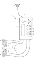
以下、本発明の好ましい実施形態について、添付図面を参照して説明する。図1は、音源装置1の概略正面図である。音源装置1には、パッド(打面)を接続するためのジャック(図示せず)が設けられており、パッドから延びるケーブルの先端に設けられた端子を、そのパッドに対応するジャックに挿入することにより、パッドが接続される。音源装置1は、接続されたパッドが打撃されたことに基づく楽音(音)を生成し、出力する装置である。
Hereinafter, preferred embodiments of the present invention will be described with reference to the accompanying drawings. FIG. 1 is a schematic front view of the
図1に示す例では、音源装置1には、スタンドSに設置された4つのパッド(タムのパッド)51〜54が接続されている。よって、音源装置1は、これらのパッド51〜54のうち、打撃されたパッドに基づく楽音を生成し、生成した楽音を、接続されるスピーカ41へと出力する。なお、音源装置1は、タムのパッド51〜54以外のパッド(例えば、スネアや、ハイハットなどのパッド)も接続可能に構成されている。
In the example shown in FIG. 1, four pads (tom pads) 51 to 54 installed on a stand S are connected to the
音源装置1は、本発明の発音制御装置の一実施形態である発音制御装置100(図2参照)を搭載する。発音制御装置100は、接続されたパッド(本実施形態では、パッド51〜54)のうち、いずれかのパッドに発音のトリガとなる振動がトリガ信号として検出された場合に、そのトリガ信号に対して算出されたクロストーク量(他パッドから受けたクロストークの度合いを示す値)に基づき、必要に応じて、クロストークキャンセルを行う装置である。
The
本実施形態の発音制御装置100は、クロストークキャンセルが実際に実行されたか否かにかかわらず、算出されたクロストーク量をLCD15に表示させる。よって、ユーザは、あるパッドを対象パッドとし、その対象パッドが他パッドから受けたクロストークの度合いを、クロストークキャンセルがされたか否かにかかわらず、表示されたクロストーク量から把握することができる。特に、発音制御装置100は、算出されたクロストーク量を表示するクロストークモニタ画面61(図4参照)に、クロストークキャンセルを行うか否かの判定に用いるクロストークキャンセル設定値を合わせて表示させるので、ユーザは、クロストークモニタ画面61に表示されたクロストークキャンセル設定値とクロストーク量とに基づいて、適切にクロストークキャンセルを行い得るクロストークキャンセル設定値を設定できる。
The sound
音源装置1の正面には、各種情報を表示する表示部であるLCD15と、入力用の操作子16とが設けられている。操作子16は、ロータリエンコーダ16aと、カーソル移動ボタン16bと、選択ボタン16cと、ENTERボタン16dと、EXITボタン16eとを含む。
On the front surface of the
図2は、音源装置1の電気的構成を示すブロック図である。音源装置1は、CPU11と、ROM12と、RAM13と、フラッシュメモリ14と、LCD15と、操作子16と、入力部17〜20と、音源21と、デジタルアナログコンバータ(DAC)22とを有している。なお、発音制御装置100は、CPU11と、ROM12と、RAM13と、フラッシュメモリ14とから構成される。各部11〜21は、バスライン23を介して互いに接続される。入力部17〜20には、それぞれ、パッド51〜54が接続される。DAC22は、音源21に接続される。
FIG. 2 is a block diagram showing an electrical configuration of the
CPU11は、ROM12に記憶される固定値やプログラム、RAM13やフラッシュメモリ14に記憶されているデータなどに従って、音源装置1の各部を制御する中央制御装置である。CPU11は、クロック信号を計数することにより、時刻を計時するタイマ(図示せず)を内蔵している。
The
ROM12は、書き替え不能な不揮発性メモリであって、CPU11や音源21に実行させる制御プログラム12aや、この制御プログラム12aが実行される際にCPU11により参照される固定値データ(図示せず)などが記憶される。なお、図6〜8のフローチャートに示す各処理は、制御プログラム12aに基づいて実行される。
The
RAM13は、書き替え可能な揮発性メモリであり、CPU11が制御プログラム12aを実行するにあたり、各種のデータを一時的に記憶するためのテンポラリエリアを有する。RAM13のテンポラリエリアには、クロストークモニタ画面61(図4参照)に表示するための各種情報が記憶される表示用情報エリア13aが設けられている。表示用情報エリア13aの詳細については、図3(a)を参照して後述する。
The
フラッシュメモリ14は、書き替え可能な不揮発性メモリである。フラッシュメモリ14には、クロストークキャンセル設定値を記憶する設定値エリア14aが設けられている。設定値エリア14aの詳細については、図3(b)を参照して後述する。
The
入力部17〜20は、それぞれ、各パッド51〜54の振動センサ51a〜54aを接続するインターフェイスである。なお、図2では省略しているが、音源装置1には、入力部17〜20と同様の入力部が、パッド51〜54以外に接続可能なパッド毎に設けられている。
The
各入力部17〜20は、接続されるパッドが異なること以外、同じ構成とされるので、以下では、入力部17を代表として説明する。パッド51の振動センサ51aから出力されたアナログ信号は、入力部17を介して音源装置1に入力される。入力部17には、アナログデジタルコンバータ(図示せず)が内蔵されている。パッド51の振動センサ51aから入力されるアナログ信号は、アナログデジタルコンバータによって所定時間毎にデジタル値に変換され、CPU11に出力される。CPU11は、パッド51の振動センサ51aから、入力部17を介して、所定レベルを超える信号が所定期間に亘って検出された場合に、その信号のピークをトリガ信号として検出する。CPU11は、トリガ信号を検出すると、クロストークキャンセルを実行するか否かの判定を行い、クロストークキャンセルを実行しないと判定した場合に、パッド51に対応する音色の楽音をトリガ信号のレベルに応じた音量で出力するよう指示する発音指示を、音源21へ出力する。一方、CPU11は、クロストークキャンセルを実行すると判定した場合には、発音指示を出力しない(クロストークキャンセルを実行する)。
Since the
音源21は、CPU11から発音指示を受けた場合に、その発音指示に従う音色及び音量の楽音を発生する。音源21には、波形ROM(図示せず)が内蔵される。この波形ROMには、パッド51〜54にそれぞれ対応する音色など、音源装置1において発音可能な音色のデジタル楽音が記憶されている。また、音源21には、フィルタやエフェクトなどの処理を行う、図示されないDSP(Digital Signal Processor)が内蔵される。音源21は、発音指示がCPU11から入力された場合に、その発音指示に従う音色のデジタル楽音を波形ROMから読み出し、DSPにおいてフィルタやエフェクトなどの所定の処理を行い、処理後のデジタル楽音をDAC22へ出力する。DAC22は、入力されたデジタル楽音をアナログ楽音に変換し、音源装置1に接続されるスピーカ41へ出力する。これにより、音源装置1に接続されるパッドの打撃に基づく楽音がスピーカ41から放音される。
When the
ここで、図3(a)を参照して、上述した表示用情報エリア13aについて説明する。図3(a)は、表示用情報エリア13aに記憶される記憶内容を模式的に示す図である。図3(a)に示すように、表示用情報エリア13aには、エリア13a1〜13a7が設けられている。エリア13a1〜13a7のうち、エリア13a1〜13a3には、音源装置1に接続されたパッドを特定する情報が記憶される。残りのエリア13a4〜13a7には、エリア13a1〜13a3により特定されるパッドに対応する表示用情報が記憶される。
Here, the
エリア13a1は、音源装置1に設けられている各ジャック(図示せず)に対して割り振られた番号(以下「ジャック番号」と称す)が記憶されているエリアである。本実施形態では、ジャック番号1〜11がエリア13a1に記憶される。つまり、音源装置1には、11のジャックが設けられている。
The area 13a1 is an area in which numbers assigned to the respective jacks (not shown) provided in the sound source device 1 (hereinafter referred to as “jack numbers”) are stored. In the present embodiment,
エリア13a2は、各ジャック番号に接続される端子名が記憶されている。本実施形態では、パッド番号1〜11に対し、それぞれ、K、S、T1、T2、T3、T4、HH、C1、C2、RD、およびEGが割り当てられている。K、S、T1、T2、T3、T4、HH、C1、C2、RD、およびEGは、それぞれ、キック、スネア、第1のタム、第2のタム、第3のタム、第4のタム、ハイハット、第1のクラッシュシンバル、第2のクラッシュシンバル、ライドシンバルのベル、およびライドシンバルのエッジから延びる端子を示す。上記端子名のうち、T1、T2、T3、およびT4が、それぞれ、パッド51〜54から延びる端子に対応する。なお、以下では、同じパッドにおける異なる部位である、ライドシンバルのベルおよびエッジについても、パッドとして説明する。
In the area 13a2, the names of terminals connected to the jack numbers are stored. In this embodiment, K, S, T1, T2, T3, T4, HH, C1, C2, RD, and EG are assigned to pad
エリア13a3には、各ジャック番号(即ち、各パッド)に対応付けられた接続フラグが設けられる。接続フラグは、対応するジャック番号のジャックに、そのジャックに対応する端子が接続されているか否かを示すフラグである。具体的に、接続フラグに1が設定されている場合、そのジャックに対応する端子が接続されていることを示す。一方、接続フラグがゼロに設定されている場合、そのジャックに対応する端子が接続されていないことを示す。接続フラグの設定は、ジャックに対応する端子が接続されているか否かに応じて変更される。 In the area 13a3, a connection flag associated with each jack number (that is, each pad) is provided. The connection flag is a flag indicating whether or not a terminal corresponding to the jack is connected to the jack of the corresponding jack number. Specifically, when the connection flag is set to 1, it indicates that the terminal corresponding to the jack is connected. On the other hand, when the connection flag is set to zero, it indicates that the terminal corresponding to the jack is not connected. The setting of the connection flag is changed depending on whether or not the terminal corresponding to the jack is connected.
エリア13a4には、各ジャック番号に対応付けられた打撃フラグが設けられる。打撃フラグは、対応するジャック番号のジャックを介して入力されたトリガ信号に対する打撃判定の結果を示すフラグである。具体的に、打撃フラグに1が設定されている場合、CPU11が、対応するジャックを介して入力されたトリガ信号を打撃によるものであると判定したことを示す。図3(a)に示す例では、ジャック番号4に接続されているパッド52から入力されたトリガ信号に対し、CPU11が打撃によるものであると判定したことを示す。
The area 13a4 is provided with a batting flag associated with each jack number. The batting flag is a flag indicating the result of batting judgment on the trigger signal input via the jack with the corresponding jack number. Specifically, when 1 is set in the batting flag, it indicates that the
あるパッドから入力されたトリガ信号に対し、CPU11が打撃によるものであると判定した場合に、トリガ信号が入力されたジャックに対応する打撃フラグに1が設定される。1に設定された打撃フラグは、その後、自パッドのクロストーク量算出用エンベロープ71(図5参照)が生成されている場合には、その減衰が完了し、かつ、他パッドのクロストークキャンセル用エンベロープ72(図5参照)が生成されている場合には、その減衰が全て完了したことを条件としてクリアされる(ゼロに設定される)。また、あるパッドに対する打撃フラグがセットされた場合、その他のパッドに対する打撃フラグは自動的にクリアされる。
When the
エリア13a5には、各ジャック番号に対応付けられたクロストークキャンセルフラグが設けられる。クロストークキャンセルフラグは、対応するジャック番号のジャックを介して入力されたトリガ信号に対し、クロストークキャンセルが実行された否かを示すフラグである。具体的に、クロストークキャンセルフラグに1が設定されている場合、対応するジャックを介して入力されたトリガ信号に対し、クロストークキャンセルが実行されたことを示す。図3(a)に示す例では、ジャック番号5に接続されているパッド53から入力されたトリガ信号に対し、クロストークキャンセルが実行されたことを示す。
In the area 13a5, a crosstalk cancellation flag associated with each jack number is provided. The crosstalk cancellation flag is a flag indicating whether or not crosstalk cancellation has been executed for a trigger signal input via a jack with a corresponding jack number. Specifically, when the crosstalk cancellation flag is set to 1, it indicates that crosstalk cancellation has been executed for a trigger signal input via the corresponding jack. In the example shown in FIG. 3A, it is shown that the crosstalk cancellation has been executed for the trigger signal input from the
あるパッドから入力されたトリガ信号に対し、クロストークキャンセルが実行されると、トリガ信号が入力されたジャックに対応するクロストークキャンセルフラグが1に設定される。1に設定されたクロストークキャンセルフラグは、その後、自パッドのクロストーク量算出用エンベロープ71が生成されている場合には、その減衰が完了し、かつ、他パッドのクロストークキャンセル用エンベロープ72が生成されている場合には、その減衰が全て完了したことを条件としてクリアされる(ゼロに設定される)。また、打撃フラグがセットされた場合や、端子が抜かれた場合には、その都度、対応するクロストークキャンセルフラグがクリアされる。また、後述するクロストークフラグがセットされた場合も、対応するクロストークキャンセルフラグがクリアされる。
When crosstalk cancellation is executed for a trigger signal input from a certain pad, a crosstalk cancellation flag corresponding to the jack to which the trigger signal is input is set to 1. After that, when the crosstalk
エリア13a6には、各ジャック番号に対応付けられたクロストークフラグが設けられる。クロストークフラグは、他パッドから受けたクロストークにより発音されたか否かを示すフラグである。具体的に、クロストークフラグに1が設定されている場合、CPU11が、対応するジャックを介して入力されたトリガ信号を、他パッドから受けたクロストークによるトリガ信号であって、かつ、クロストークキャンセルの実行対象でない(即ち、発音対象である)トリガ信号であると判定したことを示す。図3(a)に示す例では、ジャック番号3,6に接続されているパッド51,54から入力されたトリガ信号に対し、CPU11が、他パッドから受けたクロストークによるトリガ信号であって、かつ、発音対象のトリガ信号であると判定したことを示す。
In the area 13a6, a crosstalk flag associated with each jack number is provided. The crosstalk flag is a flag indicating whether or not a sound is generated by crosstalk received from another pad. Specifically, when the crosstalk flag is set to 1, the
あるパッドから入力されたトリガ信号に対し、CPU11が、他パッドから受けたクロストークによるトリガ信号であって、かつ、発音対象のトリガ信号であると判定した場合に、トリガ信号が入力されたジャックに対応するクロストークフラグに1が設定される。1に設定されたクロストークフラグは、その後、自パッドのクロストーク量算出用エンベロープ71が生成されている場合には、その減衰が完了し、かつ、他パッドのクロストークキャンセル用エンベロープ72が生成されている場合には、その減衰が全て完了したことを条件としてクリアされる(ゼロに設定される)。また、打撃フラグが1に設定された場合や、端子が抜かれた場合、その都度、対応するクロストークフラグがクリアされる。また、上述したクロストークキャンセルフラグが1に設定された場合も、対応するクロストークフラグがクリアされる。
The jack to which the trigger signal is input when the
エリア13a7には、各ジャック番号に対応付けられたクロストーク量が記憶される。クロストーク量は、他パッドから受けたクロストークの度合いを示す値である。詳細は後述するが、クロストーク量は、あるパッドから入力されたトリガ信号のレベル(振動レベル)と、他パッドから入力されたトリガ信号に基づき生成されたクロストーク量算出用エンベロープ71とに基づいて算出される。あるパッドから入力されたトリガ信号に対しクロストーク量が算出されると、算出されたクロストーク量が、トリガ信号が入力されたジャックに対応付けてエリア13a7に記憶される。記憶されたクロストーク量は、その後、自パッドのクロストーク量算出用エンベロープ71が生成されている場合には、その減衰が完了し、かつ、他パッドのクロストークキャンセル用エンベロープ72が生成されている場合には、その減衰が全て完了したことを条件として、クリアされる。また、打撃フラグが1に設定された場合や、端子が抜かれた場合、その都度、対応するクロストーク量はクリアされる。
The area 13a7 stores the amount of crosstalk associated with each jack number. The amount of crosstalk is a value indicating the degree of crosstalk received from other pads. Although details will be described later, the crosstalk amount is based on the level (vibration level) of the trigger signal input from a certain pad and the
図3(a)に示す例によれば、パッド51,53,54から入力されたトリガ信号に対して算出されたクロストーク量が、それぞれ、18,15,22であることを示す。なお、クロストーク量が算出されるパッドから入力されたトリガ信号は、他パッドから受けたクロストークによるものであると判定されるトリガ信号である。一方、パッド52から入力されたトリガ信号は、打撃であるとCPU11により判定されている(打撃フラグに1が設定されている)ので、クロストーク量はゼロである。
According to the example shown in FIG. 3A, the crosstalk amounts calculated for the trigger signals input from the
次に、図3(b)を参照して、上述した設定値エリア14aについて説明する。図3(b)は、設定値エリア14aに記憶される記憶内容を模式的に示す図である。図3(b)に示すように、設定値エリア14aには、エリア14a1〜14a3が設けられている。エリア14a1は、上述したエリア13a1と同様、ジャック番号が記憶されているエリアである。エリア14a2は、上述したエリア13a2と同様、各ジャック番号に接続される端子名が記憶されている。
Next, the
エリア14a3は、各ジャック番号に対応付けられたクロストークキャンセル設定値が記憶される。クロストークキャンセル設定値は、あるパッドから入力されたトリガ信号に対するクロストークキャンセルの実行判定に使用する値である。より詳細には、クロストークキャンセル設定値により、クロストークキャンセルを実行するか否かの閾値(クロストークキャンセル用レベル)が算出される。クロストークキャンセル設定値が大きい程、クロストークキャンセル用レベルが大きくなる。つまり、この値が大きい程、クロストークキャンセルがかかり難くなる。 In the area 14a3, a crosstalk cancel setting value associated with each jack number is stored. The crosstalk cancel setting value is a value used for execution determination of crosstalk cancellation for a trigger signal input from a certain pad. More specifically, a threshold value (crosstalk cancellation level) as to whether or not to execute crosstalk cancellation is calculated from the crosstalk cancellation setting value. The greater the crosstalk cancel setting value, the greater the crosstalk cancel level. That is, the larger this value is, the more difficult it is to cancel the crosstalk.
製品の出荷時には、設定値エリア14a(エリア14a3)には、クロストークキャンセル設定値の初期値としての値が記憶されている。なお、この製品出荷時の値は、ROM12内の図示されないエリアにも記憶されている。本実施形態では、エリア14a3に記憶されているクロストークキャンセル設定値は、ユーザの必要に応じてパッド単位で変更できるように構成されている。詳細は後述するが、例えば、クロストークモニタ画面61(図4参照)内のFOCUSボタン61d及びSETボタン61eの操作により、カーソルが合っているパッドに対して算出されたクロストーク量を、そのパッドに対するクロストークキャンセル設定値として設定できる。
At the time of product shipment, the setting
次に、図4を参照して、本実施形態の音源装置1(発音制御装置100)がLCD15に表示するクロストークモニタ画面61について説明する。図4は、クロストークモニタ画面61の模式図である。
Next, the
クロストークモニタ画面61は、音源装置1に接続された各パッドにおける相互のクロストークおよびクロストークキャンセルの状況をモニタする画面である。また、クロストークモニタ画面61は、各パッドに対するクロストークキャンセル設定値の設定画面でもある。
The
図4に示すように、クロストークモニタ画面61には、音源装置1に接続可能なパッド名(より詳細には、端子名)61aと、各パッドのクロストークキャンセル設定値61bと、各パッドに対するクロストーク情報61cと、FOCUSボタン61dと、SETボタン61eとが表示される。
As shown in FIG. 4, the
パッド名61a及びクロストークキャンセル設定値61bは、それぞれ、設定値エリア14aに記憶されている端子名及びクロストークキャンセル設定値である。パッド名61a及びクロストークキャンセル設定値61bは、ジャック番号毎に互いに対応付けられて(図4に示す例では、上下に配置されて)表示される。
The pad name 61a and the crosstalk
クロストーク情報61cは、クロストーク量61c1と、棒グラフ61c2と、マーク61c3とから構成される。クロストーク量61c1は、他パッドからのトリガ信号に基づいて生成されたクロストーク量算出用エンベロープ71(図5参照)に基づいて算出されたクロストーク量(単位:%)である。より具体的には、表示用情報エリア13aのエリア13a7に記憶されているクロストーク量のうち、0を超える値がクロストーク量61c1として表示される。
The
棒グラフ61c2は、各パッドから入力されたトリガ信号のレベルを棒グラフ状に表示したものである。棒グラフ61c2の長さが長い程、トリガ信号のレベルが大きいことを示す。棒グラフ61cの長さは、打撃であると判定されたトリガ信号のレベルを100としたときの比率に応じた長さにされる。
The bar graph 61c2 displays the level of the trigger signal input from each pad in a bar graph shape. The longer the bar graph 61c2, the higher the trigger signal level. The length of the
本実施形態の発音制御装置100は、発音されたか否かに応じて、棒グラフ61c2の表示態様を異ならせている。具体的に、発音されなかったパッドに対する棒グラフ61c2は、棒グラフを表示するための各ブロックが白抜きのブロックとして表示される。つまり、表示用情報エリア13aのエリア13a5に記憶されているクロストークキャンセルフラグに1が設定されているパッドについては、棒グラフ61c2を形成する各ブロックが白抜きのブロックとして表示される。
The sound
一方、発音されたパッドに対する棒グラフ61c2は、棒グラフ61c2を形成する各ブロックが塗り潰されたブロックとして表示される。つまり、表示用情報エリア13aのエリア13a4に記憶されている打撃フラグに1が設定されているパッドと、エリア13a6に記憶されているクロストークフラグに1が設定されているパッドについては、棒グラフ61c2を形成する各ブロックが塗り潰しのブロックとして表示される。
On the other hand, the bar graph 61c2 for the sounded pad is displayed as a block in which each block forming the bar graph 61c2 is filled. That is, the bar graph 61c2 for the pad for which 1 is set in the batting flag stored in the area 13a4 of the
図4に示す例では、T3(パッド名61a)に対する棒グラフ61c2では、各ブロックが白抜きのブロックとして表示されており、パッド53から入力されたトリガ信号に対してクロストークキャンセルが実行され、発音されなかったことを示す。一方、T1,T2,T4(パッド名61a)に対する各棒グラフ61c2では、各ブロックが塗り潰しのブロックとして表示されており、パッド51,52,54から入力されたトリガ信号に対して発音されたことを示す。
In the example shown in FIG. 4, in the bar graph 61c2 for T3 (pad name 61 a ), each block is displayed as a white block, and crosstalk cancellation is executed for the trigger signal input from the
マーク61c3は、他パッドから受けたクロストークにより発音されたパッドであると判定されたパッドに対して表示されるマークである。つまり、マーク61c3が表示されたパッドは、他パッドから受けたクロストークにより発音されたと判定されたパッドであることを示す。より具体的には、マーク61c3は、表示用情報エリア13aのエリア13a6に記憶されているクロストークフラグに1が設定されているパッドに対して表示される。図4に示す例では、T1,T4(パッド名61a)に対し、マーク61c3として、塗り潰しの三角形(▲)が表示されている。よって、パッド51,54が、他パッドから受けたクロストークにより発音されたと判定されたパッドであることを示す。
The mark 61c3 is a mark displayed for a pad that is determined to be a pad that is sounded by crosstalk received from another pad. That is, the pad on which the mark 61c3 is displayed indicates that the pad is determined to be generated by the crosstalk received from another pad. More specifically, the mark 61c3 is displayed for a pad whose crosstalk flag is set to 1 stored in the area 13a6 of the
一方、T3(パッド名61a)のように、クロストーク量61cが表示されているが、棒グラフ61c2が白抜きのブロックにより表示されている(即ち、発音されていない)パッドは、クロストークキャンセルが実行されたパッドであることを示す。このように、本実施形態の発音制御装置100は、他パッドからクロストークを受けたパッドについて、クロストークキャンセルが実行されたか否かと、発音されたか否かとに応じて表示態様を変化させているので、ユーザは、クロストークモニタ画面61の目視により、クロストークキャンセルの成否を容易に把握できる。
On the other hand, as shown in T3 (pad name 61 a ), the
FOCUSボタン61dは、FOCUS機能を呼び出すためのボタンである。FOCUS機能は、クロストークキャンセル設定値に合わせるカーソルCuを、マーク61c3が表示されたパッド(即ち、他パッドから受けたクロストークにより発音されたパッド)に限って移動させる機能である。つまり、図4に示す例では、FOCUS機能を呼び出す毎に、カーソルCuが、マーク61c3が表示されているT1,T4(パッド名61a)に対応するクロストークキャンセル設定値に対して交互に移動される。
The
SETボタン61eは、SET機能を呼び出すためのボタンである。SET機能は、カーソルCuが合っているクロストークキャンセル設定値を、表示中のクロストーク量61cに変更する機能である。よって、FOCUS機能とSET機能との組み合わせにより、他パッドから受けたクロストークにより発音されたパッドに対するクロストークキャンセル設定値を、実際に算出されたクロストーク量に変更できる。つまり、クロストークキャンセル設定値を、同じトリガ信号のレベルであればクロストークキャンセルできる値に変更できる。
The
FOCUS機能及びSET機能の呼び出しは、それぞれ、FOCUSボタン61d及びSETボタン61eが選択状態である場合に、ENTERボタン16d(図1参照)が操作された場合に実行される。また、各ボタンボタン61d,61eの選択状態は、選択ボタン16c(図1参照)が操作される毎に交互に切り換えられる。
The calling of the FOCUS function and the SET function is executed when the
なお、クロストークモニタ画面61において、カーソルCuの移動は、カーソル移動ボタン16b(図1参照)の操作によっても行うことができる。カーソルCuは、カーソル移動ボタン16bが操作される毎に、操作されたボタン16bに応じた向き(右方向又は左方向)に1つずつ移動する。カーソル移動ボタン16bを操作してカーソルCuを移動させた場合には、カーソルCuが合っているクロストークキャンセル設定値を、ロータリエンコーダ16aの回転(回転方向及び回転量)に応じて増減できる。
On the
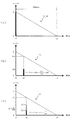
次に、図5を参照して、クロストーク量算出用エンベロープ71及びクロストークキャンセル用エンベロープ72について説明する。図5(a)は、クロストーク量算出用エンベロープ71及びクロストークキャンセル用エンベロープ72の形状を示す模式図である。なお、図5(a)において、横軸は時刻を示し、縦軸はレベルを示す。
Next, the crosstalk
クロストーク量算出用エンベロープ71は、あるパッドが、他パッドから受けたクロストークの度合いを示す値(即ち、クロストーク量)を算出するために用いるエンベロープである。一方、クロストークキャンセル用エンベロープ72は、あるパッドから入力されたトリガ信号に対し、クロストークキャンセルを実行するか否かを判定するために用いるエンベロープである。
The crosstalk
クロストーク量算出用エンベロープ71及びクロストークキャンセル用エンベロープ72は、いずれも、生成対象となるトリガ信号を出力したパッドの振動状況を模した仮想的なエンベロープであり、図5(a)に示すように、生成対象となるトリガ信号のレベルに基づいて生成される。具体的に、エンベロープ71,72は、生成対象となるトリガ信号が時刻t1において発生した場合に、時刻t1におけるトリガ信号のレベルLが、一定時間(本実施形態では、200msec)後の時刻t2においてゼロになるような一次関数により表わされる。つまり、クロストーク量算出用エンベロープ71及びクロストークキャンセル用エンベロープ72は、いずれも、生成対象となるトリガ信号のレベルが大きい程、減少の傾きが大きい。
Each of the crosstalk
生成対象となるトリガ信号は、クロストーク量算出用エンベロープ71について、打撃されたと判定されたパッドからのトリガ信号である。つまり、クロストーク量算出用エンベロープ71は、打撃されたと判定されたパッドに対して1つだけ生成される。
The trigger signal to be generated is a trigger signal from a pad determined to have been struck with respect to the crosstalk
一方、クロストークキャンセル用エンベロープ72について、生成対象となるトリガ信号は、打撃されたと判定されたパッドからのトリガ信号、又は、他パッドから受けたクロストークにより発音されたと判定されたパッドからのトリガ信号である。つまり、クロストークキャンセル用エンベロープ72は、打撃されたと判定されたパッドと、クロストークを受けたが発音されたパッドとに対し、1または複数生成される。なお、打撃されたと判定されたパッドに対して生成されたクロストークキャンセル用エンベロープ72は、クロストーク量算出用エンベロープ71と同じ形状のエンベロープとなる。
On the other hand, for the
図5(b)は、クロストーク量算出用エンベロープ71を用いたクロストーク量の算出方法を説明する図である。クロストーク量は、あるパッドからトリガ信号が入力された場合に、他パッドに対するクロストーク量算出用エンベロープ71が既に生成されている場合に、そのクロストーク量算出用エンベロープ71における現在値と、入力されたトリガ信号との比率として算出される。
FIG. 5B is a diagram for explaining a method of calculating the crosstalk amount using the
具体的に、あるパッドから時刻x1に入力されたトリガ信号のレベルをy1bとし、他パッドに対して生成されたクロストーク量算出用エンベロープ71における時刻x1に対する現在値をy1aとした場合に、あるパッドが受けたクロストーク量(%)は、(y1b/y1a)×100として算出される。
Specifically, when the level of the trigger signal input from a certain pad at time x1 is y1b and the current value at time x1 in the crosstalk
図5(c)は、クロストークキャンセル用エンベロープ72を用いて行うクロストークキャンセルの判定方法を説明する図である。あるパッドからのトリガ信号に対し、クロストークキャンセルを行うか否かの判定は、生成されているクロストークキャンセル用エンベロープ72のうち、判定対象となるトリガ信号が入力された時刻における現在値が最大となるエンベロープ72を用いて行う。より詳細には、クロストークキャンセルを行うか否かの判定は、判定に用いるクロストークキャンセル用エンベロープ72における現在値(即ち、判定対象となるトリガ信号が入力された時刻)に、判定対象となるトリガ信号の出力元のパッドに対して規定されるキャンセルレートを乗算して得られるクロストークキャンセル用レベルと、判定対象となるトリガ信号のレベルとの比較によって行う。前者が後者より大きい場合、判定対象となるトリガ信号に対しクロストークキャンセルを実行すると判定される。一方、前者が後者より小さい場合、判定対象となるトリガ信号に対しクロストークキャンセルを実行しないと判定される。
FIG. 5C is a diagram for explaining a crosstalk cancellation determination method performed using the
「キャンセルレート」は、各パッドに対して設定されているクロストークキャンセル設定値を、100で除した値である。つまり、クロストークキャンセル設定値をAとした場合、キャンセルレートは、A/100で表わされる。クロストークキャンセルを行うか否かの判定を行う場合には、値A(クロストークキャンセル設定値)として、判定対象となるトリガ信号の出力元のパッドに対して設定されているクロストークキャンセル設定値を使用する。 The “cancellation rate” is a value obtained by dividing the crosstalk cancellation setting value set for each pad by 100. That is, when the crosstalk cancellation setting value is A, the cancellation rate is represented by A / 100. When determining whether or not to perform crosstalk cancellation, the value A (crosstalk cancellation setting value) is the crosstalk cancellation setting value set for the pad from which the trigger signal to be determined is output. Is used.
具体的に、1または複数生成されているクロストークキャンセル用エンベロープ72のうち、あるパッドからトリガ信号が入力された時刻x2における現在値の最大値がy2である場合に、入力されたトリガ信号のレベルと、クロストークキャンセル用レベルであるy2×(A/100)とを比較する。(A/100)は、当該トリガ信号の出力元のパッドに対して規定されるキャンセルレートである。この場合、例えば、あるパッドから入力されたトリガ信号(判定対象のトリガ信号)のレベルが、y2×(A/100)より小さいL2であれば、当該トリガ信号に対しクロストークキャンセルを実行すると判定される。一方、判定対象のトリガ信号のレベルが、y2×(A/100)より大きいL1であれば、当該トリガ信号に対しクロストークキャンセルを実行しない、即ち、発音対象のトリガ信号であると判定される。
Specifically, of the one or a plurality of generated
次に、図6から図8を参照して、上記構成を有する音源装置1(発音制御装置100)のCPU11が実行する処理について説明する。まず、図6は、CPU11が実行する発音制御処理を示すフローチャートである。CPU11は、パッドからのトリガ信号(所定期間に亘って所定レベルを超える信号のピーク)を検出した場合に、発音制御処理を実行する。発音制御処理は、音源装置1に接続されたパッド毎に実行される。本実施形態では、音源装置1には、パッド51〜54(振動センサ51a〜54a)が接続されているので、発音制御処理は、パッド51〜54についてそれぞれ実行される。以下では、代表として、パッド51についてそれぞれ実行される発音制御処理を説明するが、パッド51以外のパッド(パッド52〜54や、音源装置1に接続可能なその他のパッド)についても同様である。
Next, processing executed by the
発音制御処理において、CPU11は、まず、他パッド(パッド52〜54のうち、いずれか1つのパッド)が生成したクロストーク量算出用エンベロープ71が減衰完了しているか否かの判定と、自パッド(パッド51)が生成したクロストーク量算出用エンベロープ71が減衰完了しているか否かの判定とを実行する(S601,S602)。
In the sound generation control process, the
他パッドが生成したクロストーク量算出用エンベロープ71が減衰完了し、かつ、自パッドが生成したクロストーク量算出用エンベロープ71が減衰完了しているとCPU11が判定した場合(S601:Yes,S602:Yes)、CPU11は、入力されたトリガ信号が、自パッドを打撃したことにより発生したものであるとみなし、表示用情報エリア13aに記憶される表示用情報、即ち、エリア13a4〜13a7の記憶内容をクリアする(S603)。
When the
次に、CPU11は、自パッドのトリガ信号のレベルに応じたクロストーク量算出用エンベロープ71を生成する(S604)。次に、CPU11は、自パッドを打撃パッドとして表示用情報エリア13aに記憶し(S605)、処理をS606へ移行する。具体的に、S605において、CPU11は、表示用情報エリア13a内における自パッドに対応する打撃フラグを1に設定する。
Next, the
一方、他パッドが生成したクロストーク量算出用エンベロープ71が未だ減衰完了していないとCPU11が判定した場合(S601:No)、CPU11は、クロストーク量算出処理を実行し(S611)、処理をS606へ移行する。クロストーク量算出処理(S611)は、自パッドのクロストーク量(%)を算出する処理であり、その詳細については、図7(a)を参照して後述する。つまり、他パッドが生成したクロストーク量算出用エンベロープ71が未だ減衰完了していない状況で入力されたトリガ信号は、他パッドの打撃に基づくクロストークによって生じたものである可能性があるので、クロストーク量算出処理(S611)により、クロストーク量の算出を行う。
On the other hand, when the
また、他パッドが生成したクロストーク量算出用エンベロープ71が全て減衰完了しているが、自パッドが生成したクロストーク量算出用エンベロープ71が未だ減衰完了していないとCPU11が判定した場合(S601:Yes,S602:No)、CPU11は、処理をS606へ移行する。他パッドが生成したクロストーク量算出用エンベロープ71が全て減衰完了しているが、自パッドが生成したクロストーク量算出用エンベロープ71が未だ減衰完了していない場合としては、自パッドを連打した場合など、比較的大きなトリガ信号が近接して入力された場合が想定される。よって、かかる場合には、クロストーク量算出用エンベロープ71が重複して生成されないよう、CPU11は、処理をS606へ移行する。
When the
S606において、CPU11は、クロストークキャンセル用レベル算出処理を実行する(S606)。クロストークキャンセル用レベル算出処理(S606)は、クロストークキャンセルを実行するか否かを判定するための閾値である、クロストークキャンセル用レベルを算出する処理であり、その詳細については、図7(b)を参照して後述する。
In S606, the
CPU11は、クロストークキャンセル用レベル算出処理(S606)の実行後、トリガ信号のレベルが、算出されたクロストークキャンセル用レベルを超えるか否かを判定する(S607)。トリガ信号のレベルが算出されたクロストークキャンセル用レベルを超えると、CPU11が判定した場合(S607:Yes)、CPU11は、自パッドが打撃パッドであるか否かを判定する(S608)。具体的に、S608において、CPU11は、表示用情報エリア13a内における自パッドに対応する打撃フラグの値に基づいて、自パッドが打撃パッドであるか否かを判定する。
After executing the crosstalk cancellation level calculation process (S606), the
S608において、自パッドが打撃パッドでないとCPU11が判定した場合(S608:No)、CPU11は、自パッドを、他パッドから受けたクロストークにより発音されたパッドとして表示用情報エリア13aに記憶し(S613)、処理をS609へ移行する。具体的に、S613において、CPU11は、表示用情報エリア13a内における自パッドに対応するクロストークフラグを1に設定する。一方、S608において、自パッドが打撃パッドであるとCPU11が判定した場合(S608:Yes)、CPU11は、処理をS609へ移行する。
If the
S609において、CPU11は、自パッドのトリガ信号のレベルに応じたクロストークキャンセル用エンベロープ72を生成する(S609)。次に、CPU11は、発音処理を実行し(S610)、本処理を終了する。具体的に、S610において、CPU11は、自パッド(パッド51)の楽音を発生させるための発生指示を音源21へ出力する。
In S609, the
一方、S607において、トリガ信号のレベルが算出されたクロストークキャンセル用レベル以下であると、CPU11が判定した場合(S607:No)、CPU11は、自パッドを、クロストークキャンセルが実行されたパッドとして表示用情報エリア13aに記憶し(S612)、本処理を終了する。具体的に、S612において、CPU11は、表示用情報エリア13a内における自パッドに対応するクロストークキャンセルフラグを1に設定する。よって、入力されたトリガ信号がクロストークキャンセル用レベル以下である場合には、発音処理(S610)が実行されない、即ち、クロストークキャンセルが実行される。
On the other hand, if the
図7(a)は、上述したクロストーク量算出処理(S611)を示すフローチャートである。クロストーク量算出処理(S611)において、CPU11は、まず、他パッド(パッド52〜54のうち、いずれか1つのパッド)が生成したクロストーク量算出用エンベロープ71の現在値を取得する(S701)。次に、CPU11は、S701において取得した現在値と、トリガ信号のレベルとの比率を、クロストーク量(%)として算出する(S702)。S702において算出されるクロストーク量は、例えば、上述した図5(b)に示した(y1b/y1a)×100に相当する。
FIG. 7A is a flowchart showing the above-described crosstalk amount calculation processing (S611). In the crosstalk amount calculation process (S611), the
次に、CPU11は、算出したクロストーク量を表示用情報エリア13aに記憶し(S703)、本処理を終了する。具体的に、S703において、CPU11は、表示用情報エリア13a内における自パッドに対応するクロストーク量として、算出されたクロストーク量を記憶する。
Next, the
図7(b)は、上述したクロストークキャンセル用レベル算出処理(S606)を示すフローチャートである。クロストークキャンセル用レベル算出処理(S606)において、CPU11は、まず、他パッド(パッド52〜54)が生成した全てのクロストークキャンセル用エンベロープ72における各現在値のうち、最大値を取得する(S721)。
FIG. 7B is a flowchart showing the above-described crosstalk cancellation level calculation process (S606). In the crosstalk cancellation level calculation process (S606), the
なお、上述したS601,S602において、CPU11が、他パッドが生成したクロストーク量算出用エンベロープ71が減衰完了し、かつ、自パッドが生成したクロストーク量算出用エンベロープ71が減衰完了していると判定する場合、即ち、最初にパッドが打撃された場合には、CPU11は、S721において、クロストークキャンセル用エンベロープ72のレベルをゼロとして処理する。
In S601 and S602 described above, the
次に、CPU11は、S721において取得した現在値の最大値に、自パッド(パッド51)に対して設定されているクロストークキャンセル設定値に応じたキャンセルレートを乗算して、クロストークキャンセル用レベルを取得し(S722)、本処理を終了する。S722において使用するキャンセルレートは、例えば、上述した図5(c)に示した(A/100)に相当する。また、S722において算出されるクロストークキャンセル用レベルは、例えば、上述した図5(c)に示したy2×(A/100)に相当する。
Next, the
図8は、CPU11が実行するクロストークモニタ画面処理を示すフローチャートである。クロストークモニタ画面処理は、クロストークモニタ画面61の表示に関する制御を実行する処理である。クロストークモニタ画面処理は、図示されないメイン処理において、定期的に(例えば、1msec毎に)実行される。
FIG. 8 is a flowchart showing crosstalk monitor screen processing executed by the
クロストークモニタ画面処理において、まず、クロストークモニタ画面61の表示中でないとCPU11が判定した場合には(S801:No)、本処理を終了する。一方、クロストークモニタ画面61の表示中であるとCPU11が判定した場合(S801:Yes)、CPU11は、処理をS802へ移行する。
In the crosstalk monitor screen process, first, when the
S802において、CPU11は、上述した図6及び図7のフローチャートにおいて実行される処理により、表示用情報エリア13a内における表示用情報が変更(更新又はクリア)されたか否かを判定する(S802)。表示用情報が変更されたとCPU11が判定した場合(S802:Yes)、CPU11は、その変更を、クロストークモニタ画面61の表示に反映させ(S808)、処理をS803へ移行する。一方、表示用情報が変更されていないとCPU11が判定した場合(S802:No)、CPU11は、処理をS803へ移行する。
In S802, the
S803において、CPU11は、FOCUS機能が呼び出されたか否かを判定する(S803)。FOCUS機能は、クロストークモニタ画面61内のFOCUSボタン61dが選択状態である場合に、ENTERボタン16dが操作された場合に呼び出される。FOCUS機能が呼び出されていないとCPU11が判定した場合(S803:No)、CPU11は、処理をS804へ移行する。
In S803, the
一方、FOCUS機能が呼び出されたとCPU11が判定した場合(S803:Yes)、CPU11は、他パッドから受けたクロストークにより発音されたパッド(即ち、マーク61c3が表示されているパッド)のうち、現在位置から向かって右方向に直近のパッドにカーソルCuを移動させる(S809)。S809において、カーソルCuが、マーク61c3が表示されているパッドのうち、向かって最も右側のパッドに合っている状態で、FOCUS機能が呼び出された場合には、カーソルCuを、マーク61c3が表示されているパッドのうち、向かって最も左側のパッドへ移動させる。例えば、図4に示したクロストークモニタ画面61の表示状態において、FOCUS機能が呼び出された場合には、カーソルCuは、T4(パッド54)に対応するクロストークキャンセル設定値のところへ移動する。なお、マーク61c3が表示されているパッドが存在しない場合には、FOCUS機能が呼び出されても、カーソルCuの移動は行わないものとする。
On the other hand, when the
S804において、CPU11は、SET機能が呼び出されたか否かを判定する(S804)。SET機能は、クロストークモニタ画面61内のSETボタン61eが選択状態である場合に、ENTERボタン16dが操作された場合に呼び出される。SET機能が呼び出されていないとCPU11が判定した場合(S804:No)、CPU11は、処理をS805へ移行する。
In S804, the
一方、SET機能が呼び出されたとCPU11が判定した場合(S804:Yes)、CPU11は、カーソルCuが合っているパッドに対し、設定値エリア14aに記憶されているクロストークキャンセル設定値を、表示されているクロストーク量61c1に変更し(S810)、処理をS805へ移行する。なお、S810において、設定値エリア14aに記憶されているクロストークキャンセル設定値が変更された場合、CPU11は、その変更を、クロストークモニタ画面61の表示に反映させる。つまり、変更後のクロストークキャンセル設定値61bが表示される。
On the other hand, when the
S805において、CPU11は、カーソル移動ボタン16bが操作されたか否かを判定する(S805)。カーソル移動ボタン16bが操作されていないとCPU11が判定した場合(S805:No)、CPU11は、処理をS806へ移行する。
In S805, the
一方、カーソル移動ボタン16bが操作されたとCPU11が判定した場合(S805:Yes)、CPU11は、カーソルCuを、現在位置から操作されたボタンに対応する向きに移動させ(S811)、処理をS806へ移行する。なお、S811において、カーソルCuが向かって最も右側(又は、左側)のパッドに合っている状態で、カーソル移動ボタン16bのうち、右方向(又は、左方向)へ移動させるボタンが操作された場合には、カーソルCuを、向かって最も左側(又は、右側)のパッドへ移動させる。
On the other hand, when the
S806において、CPU11は、ロータリエンコーダ16aが回転(操作)されたか否かを判定する(S806)。ロータリエンコーダ16aが回転されていないとCPU11が判定した場合(S806:No)、CPU11は、処理をS807へ移行する。
In S806, the
一方、ロータリエンコーダ16aが回転されたとCPU11が判定した場合(S806:Yes)、CPU11は、カーソルCuが合っているパッドに対し、設定値エリア14aに記憶されているクロストークキャンセル設定値を、エンコーダ16aの回転(回転方向及び回転量)に応じて増減し(S812)、処理をS807へ移行する。なお、S812において、設定値エリア14aに記憶されているクロストークキャンセル設定値が変更された場合、CPU11は、その変更を、クロストークモニタ画面61の表示に反映させる。
On the other hand, when the
S807において、CPU11は、EXITボタン16eが操作されたか否かを判定する(S807)。EXITボタン16eが操作されていないとCPU11が判定した場合(S807:No)、CPU11は、本処理を終了する。一方、EXITボタン16eが操作されたとCPU11が判定した場合(S807:Yes)、CPU11は、表示中のクロストークモニタ画面61を、予め決められた画面(例えば、電源投入時に最初に表示される基本画面)に切り替え(S813)、本処理を終了する。
In S807, the
以上説明した通り、本実施形態の音源装置1(発音制御装置100)によれば、クロストーク量61c1がクロストークモニタ画面61に表示される。その一方で、各パッドに対して設定されているクロストークキャンセル設定値61bもまた、クロストークモニタ画面61に表示される。よって、ユーザは、クロストークモニタ画面61に表示されたクロストークキャンセル設定値61bと、クロストーク量61c1とに基づいて、パッド毎に、クロストークの状況を把握することができる。例えば、クロストークキャンセル設定値61bと、クロストーク量61c1との比較から、クロストークキャンセル設定値61bが適正な値であるか否かや、変更する必要があるか否かを判断できる。
As described above, according to the sound source device 1 (the sound generation control device 100) of the present embodiment, the crosstalk amount 61c1 is displayed on the
特に、クロストーク量61c1は、クロストークキャンセルが実行されたか否かにかかわらず表示されるので、他パッドから受けたクロストークにより発音されたパッドだけでなく、クロストークキャンセルされたパッドに対しても、クロストークキャンセル設定値61bが適正な値であるか否かを判断できる。
In particular, since the crosstalk amount 61c1 is displayed regardless of whether or not the crosstalk cancellation has been executed, not only the pads that are generated by the crosstalk received from other pads but also the pads that have been crosstalk canceled. In addition, it is possible to determine whether or not the crosstalk
クロストークモニタ画面61には、クロストーク量61c1に加え、クロストークキャンセルの成否を互いに識別可能な表示態様の表示(具体的に、棒グラフ61c2の表示態様と、マーク61c3の有無との組み合わせ)が表示されるので、ユーザは、クロストークモニタ画面61の目視により、クロストークキャンセルの成否を容易に把握できる。よって、ユーザは、各パッドのクロストークの状況をより把握し易く、クロストークキャンセル設定値61bの設定をより的確に、かつ、容易に行うことができる。
On the
また、FOCUS機能の呼び出しにより、他パッドから受けたクロストークにより発音されたパッドが自動的に選択され、SET機能の呼び出しにより、FOCUS機能によって選択されたパッドに対して設定されているクロストークキャンセル設定値を、実際に算出されたクロストーク量に変更することができる。よって、クロストークキャンセル設定値を、容易な操作で適正な値に変更できる。 In addition, when the FOCUS function is called, a pad sounded by crosstalk received from another pad is automatically selected, and when the SET function is called, the crosstalk cancel set for the pad selected by the FOCUS function is selected. The set value can be changed to the actually calculated crosstalk amount. Therefore, the crosstalk cancellation setting value can be changed to an appropriate value with an easy operation.
また、本実施形態の音源装置1(発音制御装置100)によれば、あるパッド(自パッド)のクロストーク量は、他パッドの振動状況を模した仮想的なエンベロープ(クロストーク量算出用エンベロープ71)における現在値と、自パッドからのトリガ信号のレベルとの比率により算出される。つまり、自パッドのクロストーク量は、自パッドの振動(トリガ信号)のレベルと、他パッドの振動の時間的変化に従うレベルとに基づいて算出される。よって、クロストーク量を、パッドの位置関係に依存しない値として算出できるので、複数のパッドの配置の自由度を高めつつ、適切なクロストークキャンセルを行い得る。 Further, according to the sound source device 1 (the sound generation control device 100) of the present embodiment, the crosstalk amount of a certain pad (own pad) is a virtual envelope (an envelope for calculating the crosstalk amount) imitating the vibration state of other pads. 71) is calculated by the ratio between the current value in 71) and the level of the trigger signal from the own pad. That is, the crosstalk amount of the own pad is calculated based on the level of the vibration (trigger signal) of the own pad and the level according to the temporal change of the vibration of the other pad. Therefore, the amount of crosstalk can be calculated as a value that does not depend on the positional relationship of the pads, so that appropriate crosstalk cancellation can be performed while increasing the degree of freedom in arranging a plurality of pads.
また、クロストークキャンセル用レベルは、他パッドの振動状況を模した仮想的なエンベロープ(クロストークキャンセル用エンベロープ72)と、自パッドからのトリガ信号のレベルとに基づいて算出される。よって、クロストークキャンセル用レベルを、パッドの位置関係に依存しない値として算出できるので、複数のパッドの配置の自由度を高めつつ、適切なクロストークキャンセルを行い得る。 The level for canceling the crosstalk is calculated based on a virtual envelope (crosstalk canceling envelope 72) simulating the vibration state of the other pads and the level of the trigger signal from the own pad. Therefore, since the level for canceling the crosstalk can be calculated as a value that does not depend on the positional relationship between the pads, it is possible to perform appropriate crosstalk cancellation while increasing the degree of freedom of arrangement of the plurality of pads.
以上、実施形態に基づき本発明を説明したが、本発明は上記形態に何ら限定されるものではなく、本発明の趣旨を逸脱しない範囲内で種々の変形改良が可能であることは容易に推察できるものである。 As described above, the present invention has been described based on the embodiment, but the present invention is not limited to the above-described embodiment, and various modifications can be easily made without departing from the gist of the present invention. It can be done.
例えば、上記実施形態で挙げた数値は一例であり、他の数値を適宜採用することは当然可能である。 For example, the numerical values given in the above embodiment are examples, and other numerical values can be adopted as appropriate.
また、上記実施形態では、1つのパッドに対し、1つのクロストークキャンセル設定値が設定される構成としたが、パッド毎に、他の複数のパッドに対してそれぞれクロストークキャンセル設定値が対応付けられたマトリクスを持たせる構成としてもよい。 In the above embodiment, one crosstalk cancellation setting value is set for one pad. However, for each pad, a crosstalk cancellation setting value is associated with each of a plurality of other pads. It is good also as a structure which gives the prepared matrix.
このように、パッド毎にマトリクスを持たせる構成を採用する変形例では、打撃であると判定されたパッド毎に、クロストーク量算出用エンベロープ71を生成する。そして、あるパッド(自パッド)についてトリガ信号が検出された場合に、他パッドにより生成された全てのクロストーク量算出用エンベロープ71に基づいて、それぞれ、クロストーク量を算出すればよい。
As described above, in a modification employing a configuration in which a matrix is provided for each pad, a crosstalk
また、かかる変形例において、クロストークキャンセル用レベルを算出する場合には、他パッドのそれぞれに対して生成されたクロストークキャンセル用エンベロープ72に、自パッドと各他パッドに対応するキャンセルレート(クロストークキャンセル設定値/100)を乗算した後、そのうちの最大値を選択するようにすればよい。
In this modification, when calculating the crosstalk cancellation level, the
また、上記実施形態では、クロストーク量算出用エンベロープ71及びクロストークキャンセル用エンベロープ72として、パッドの振動状況を模した仮想的なエンベロープを用いる構成としたが、パッドにおける実際の振動の包絡線を、クロストーク量算出用エンベロープ71及びクロストークキャンセル用エンベロープ72として用いてもよい。
In the above embodiment, a virtual envelope imitating the vibration state of the pad is used as the crosstalk
また、上記実施形態では、仮想的なエンベロープであるエンベロープ71,72として、時間経過に伴い値が減少する一次関数(直線)で表わされるエンベロープを採用したが、時間経過に伴い値が減少する関数であれば、一次関数以外の関数(例えば、指数関数など)を採用してもよい。また、レベルが増加することなく最終的にゼロに到達するものであれば、複数種類の関数を組み合わせたものであってもよい。また、クロストーク量算出用エンベロープ71及びクロストークキャンセル用エンベロープ72を、テーブルとして持つ構成としてもよい。
In the above embodiment, the
また、上記実施形態では、クロストーク量算出用エンベロープ71及びクロストークキャンセル用エンベロープ72を、その発生から、レベルがゼロになるまでの時間が一定(例えば、200msec)であるエンベロープとした。つまり、上記実施形態で採用された一次関数のエンベロープ71,72は、トリガ信号のレベルに応じて、傾きが異なっていた。これに換えて、これらのエンベロープ71,72として、傾きが一定のエンベロープを採用してもよい。あるいは、生成されてからの経過時間に応じた減少率が、トリガ信号のレベルに依らずに共通であるエンベロープを、エンベロープ71,72として採用してもよい。これらの場合には、トリガ信号のレベルの大きい程、ゼロに到達するまでの時間が長くなる。
In the above embodiment, the crosstalk
また、上記実施形態では、打撃されたと判定されたパッドについては、クロストーク量算出用エンベロープ71とクロストークキャンセル用エンベロープ72との両方を生成する構成としたが、共通のエンベロープとし、クロストーク量を算出する場合と、クロストークキャンセル用レベルを算出する場合との両方に使用する構成としてもよい。
In the above embodiment, the pad determined to have been hit is configured to generate both the crosstalk
また、上記実施形態では、トリガ信号のレベルLが一定時間後にゼロになるようなクロストークキャンセル用エンベロープ72を生成し、クロストークキャンセル用エンベロープ72の現在値のうち、最大の値に対して、キャンセルレートを乗算することにより、クロストークキャンセル用レベルを算出した。これに対し、クロストークキャンセル用エンベロープ72を、トリガ信号のレベルLにキャンセルレートを予め乗算したレベルが一定時間後にゼロになるようなエンベロープとして生成し、クロストークキャンセル用エンベロープ72における現在値のうち、最大の値を、クロストークキャンセル用レベルとしてもよい。
Further, in the above embodiment, the
また、上記実施形態では、クロストークキャンセル設定値を、クロストークモニタ画面61においてユーザが設定変更する構成とした。これに換えて、あるパッド(自パッド)に対してクロストーク量が算出された場合には、自動的に、自パッドに設定されているクロストークキャンセル設定値を、算出されたクロストーク量に変更する構成としてもよい。かかる構成を採用することにより、ユーザがパッドを打撃する毎に、その打撃に基づきクロストーク量が算出されたパッド(即ち、他のパッドの打撃に基づくクロストークを受けたパッド)に対して設定されているクロストークキャンセル設定値を、実際に算出されたクロストーク量に自動的に変更できるので、クロストークキャンセル設定値を、容易な操作で適正な値に変更できる。
In the above-described embodiment, the crosstalk cancel setting value is changed by the user on the
図9は、この変形例における発音制御処理を示すフローチャートである。なお、図9において、上記実施形態と同一の部分には、同一の符号を付し、その説明は省略する。本変形例の発音制御処理は、音源装置1が、クロストークキャンセル設定値を自動的に変更する専用のモードに設定されている場合に実行される。
FIG. 9 is a flowchart showing the sound generation control process in this modification. In FIG. 9, the same parts as those in the above embodiment are denoted by the same reference numerals, and the description thereof is omitted. The sound generation control process of the present modification is executed when the
図9に示すように、本変形例の発音制御処理では、CPU11が、クロストーク量算出処理(S611)の実行後に、S901の処理を実行する点で、図6の発音制御処理と異なる。具体的に、S601において、他パッドが生成したクロストーク量算出用エンベロープ71が未だ減衰完了していないとCPU11が判定した場合に(S601:No)、CPU11は、クロストーク量算出処理を実行し(S611)、自パッドに対して設定値エリア14aに記憶されているクロストークキャンセル設定値を、算出されたクロストーク量に変更する(S901)。
As shown in FIG. 9, the sound generation control process of this modification differs from the sound generation control process of FIG. 6 in that the
かかる変形例において、クロストーク量が算出されたパッドのうち、クロストークキャンセルされずに発音されたパッドに対してのみ、当該パッドに対して設定されているクロストークキャンセル設定値を、算出されたクロストーク量に変更するようにしてもよい。 In such a modified example, the crosstalk cancellation setting value set for the pad is calculated only for the pad that is generated without crosstalk cancellation among the pads for which the crosstalk amount is calculated. You may make it change into the amount of crosstalk.
また、上記実施形態では、SET機能が呼び出された場合に、カーソルCuが合っているパッドに対するクロストークキャンセル設定値を、表示されているクロストーク量61c1(即ち、算出されたクロストーク量)に変更する構成としたが、算出されたクロストーク量そのものでなく、算出されたクロストーク量に基づき得られる値を、クロストークキャンセル設定値として設定する構成としてもよい。 In the above embodiment, when the SET function is called, the crosstalk cancel setting value for the pad on which the cursor Cu is positioned is set to the displayed crosstalk amount 61c1 (that is, the calculated crosstalk amount). Although the configuration is changed, a value obtained based on the calculated crosstalk amount, not the calculated crosstalk amount itself, may be set as the crosstalk cancellation setting value.
例えば、1.算出されたクロストーク量(%)に、1以上の所定の係数を乗算した値、2.算出されたクロストーク量(%)に、所定のポイント数を加算した値、3.複数の他パッドに対する各打撃に基づいて算出されたクロストーク量(%)のうちの最大値、4.1又は複数の他パッドによる複数回の打撃に基づいて算出されたクロストーク量(%)のうちの最大値、5.上記1〜4の中から状況に応じて適宜選択された値。なお、この変形例は、図9を参照して説明した、クロストークキャンセル設定値が自動的に変更される場合に対して適用してもよい。
For example: 1. a value obtained by multiplying the calculated crosstalk amount (%) by a predetermined coefficient of 1 or more; 2. a value obtained by adding a predetermined number of points to the calculated crosstalk amount (%); The maximum value of the crosstalk amount (%) calculated based on each hit with respect to a plurality of other pads, 4.1 or the crosstalk amount (%) calculated based on multiple hits with a plurality of
また、上記実施形態では、FOCUS機能を呼び出した場合に、カーソルCuを、マーク61c3が表示されたパッド(即ち、他パッドから受けたクロストークにより発音されたパッド)に限って移動させる構成としたが、クロストーク量61c1が表示されている全てのパッドをFOCUS機能によるカーソルCuの移動対象としてもよい。つまり、マーク61c3が表示されていないパッド(即ち、クロストークキャンセルされたパッド)を、FOCUS機能によるカーソルCuの移動対象に含めてもよい。FOCUS機能により、カーソルCuが、マーク61c3が表示されていないパッドにも移動されることにより、クロストークキャンセルされたが、クロストーク量に対し、クロストークキャンセル設定値が大きすぎる場合に、クロストークキャンセル設定値を、FOCUS機能とSET機能との組み合わせにより容易に適正な値に変更することが可能となる。 In the above embodiment, when the FOCUS function is called, the cursor Cu is moved only to the pad on which the mark 61c3 is displayed (that is, the pad sounded by crosstalk received from another pad). However, all the pads on which the crosstalk amount 61c1 is displayed may be the target of movement of the cursor Cu by the FOCUS function. That is, a pad on which the mark 61c3 is not displayed (that is, a pad on which crosstalk has been canceled) may be included in the movement target of the cursor Cu by the FOCUS function. When the cursor Cu is moved to the pad on which the mark 61c3 is not displayed by the FOCUS function, the crosstalk is canceled. However, the crosstalk cancel setting value is too large for the crosstalk amount. The cancel setting value can be easily changed to an appropriate value by a combination of the FOCUS function and the SET function.
また、上記実施形態では、クロストークモニタ画面61に表示されるクロストーク情報61cとして、クロストーク量61c1と、棒グラフ61c2と、マーク61c3とを表示させる構成としたが、少なくとも、クロストーク量61c1が表示されていればよい。ユーザは、各パッドに対応するクロストーク量61c1とクロストークキャンセル設定値61bとの大小関係から、クロストークされたか否かを判断できる。しかし、マーク61c3を表示したり、棒グラフ61c2の表示態様を変更したりすることにより、ユーザがクロストークの状況を把握し易くなるので、好ましい。
In the above embodiment, the crosstalk amount 61c1, the bar graph 61c2, and the mark 61c3 are displayed as the
また、上記実施形態では、クロストークモニタ画面61に表示されるクロストーク量61c1を数値により表示したが、棒グラフや図形の大きさなど、クロストーク量の大きさを報知可能な態様で、クロストーク量61c1を表示してもよい。かかる場合には、クロストークキャンセルされたパッドであるか、他パッドから受けたクロストークにより発音されたパッドであるかに応じて、棒グラフや図形の表示態様(例えば、塗り潰しや着色の有無など)を異ならせるようにしてもよい。
In the above embodiment, the crosstalk amount 61c1 displayed on the
また、上記実施形態では、他パッドから受けたクロストークにより発音されたパッドに対してマーク61c3を表示させる構成としたが、クロストークキャンセルされたパッドに対しても、他パッドから受けたクロストークにより発音されたパッドとは異なる表示態様(例えば、図形内の塗り潰しや着色の有無や、図形の相違など)のマークを表示する構成としてもよい。かかる場合、例えば、棒グラフ61c2の表示態様を、クロストークキャンセルされたか否かにかかわらず同じ表示態様としてもよい。 In the above-described embodiment, the mark 61c3 is displayed on the pad that is generated by the crosstalk received from the other pad. However, the crosstalk received from the other pad is also displayed on the pad on which the crosstalk is canceled. It is good also as a structure which displays the mark of the display mode (For example, the presence or absence of the filling and coloring in a figure, the difference of a figure, etc.) different from the pad sounded by. In such a case, for example, the display mode of the bar graph 61c2 may be the same display mode regardless of whether or not the crosstalk is canceled.
また、図6及び図9の発音制御処理では、S608において、自パッドが打撃パッドでないとCPU11が判定した場合であっても(S608:No)、CPU11は、S609を実行し、クロストークキャンセル用エンベロープ72を生成した。これに換えて、S608において、自パッドが打撃パッドでないとCPU11が判定した場合には(S608:No)、クロストークキャンセル用エンベロープ72が生成されない構成としてもよい。つまり、かかる場合には、自パッドが打撃パッドであるとCPU11が判定した場合にのみ、CPU11は、クロストークキャンセル用エンベロープ72を生成するようにしてもよい。しかし、S608において、自パッドが打撃パッドでないとCPU11が判定した場合にも、実際には打撃されている可能性もあり得るので、図6及び図9の発音制御処理のように、発音されたトリガ信号に対し、打撃されたか否かの判定とは無関係にクロストークキャンセル用エンベロープ72を生成することが好ましい。
Further, in the sound generation control process of FIGS. 6 and 9, even if the
また、上記実施形態では、通常演奏時に、他パッドの打撃に基づくクロストークをキャンセルするための処理について説明したが、パッドの打撃によって画面や設定を切り替え可能な装置において、他パッドの打撃に基づくクロストークによって画面や設定が誤って切り替わることを防ぐために、上記実施形態と同様のクロストークキャンセルを適用できる。 Further, in the above embodiment, the processing for canceling the crosstalk based on the hit of the other pad during the normal performance has been described. However, in the device that can switch the screen and setting by the hit of the pad, the process is based on the hit of the other pad. In order to prevent the screen and settings from being switched accidentally by crosstalk, the same crosstalk cancellation as in the above embodiment can be applied.
例えば、パッド毎に設けられたエディット画面において、個々のパッドに割り当てる音色を個々に設定できる装置が、エディット対象とするパッドを打撃することによって、対応するエディット画面を表示できるように構成されている場合に、クロストークにより、意図しないパッドのエディット画面が表示されてしまうことがある。このようなクロストークによる意図しない画面の切り替えを防ぐためには、通常演奏時のクロストークキャンセルと同様に、検出したトリガ信号に対しクロストークキャンセルを実行するか否かの判定に基づいて、画面の切り替えを制御させればよい。 For example, in the edit screen provided for each pad, a device that can individually set the tone assigned to each pad is configured to display the corresponding edit screen by hitting the pad to be edited. In some cases, an unintended pad edit screen may be displayed due to crosstalk. In order to prevent such unintentional screen switching due to crosstalk, the screen is determined based on the determination of whether or not to execute crosstalk cancellation for the detected trigger signal, as in the case of crosstalk cancellation during normal performance. What is necessary is just to control switching.
しかし、通常演奏時のクロストークキャンセルは、複数のパッドを同時打ちしたにもかかわらず、一部のパッドに対する打撃に対してクロストークキャンセルが実行され、発音されないということが起こり得るので、クロストークキャンセル設定値を適正な値に設定する必要がある。つまり、クロストークキャンセル設定値は、大きすぎても、小さすぎても不適切な値となる。 However, since crosstalk cancellation during normal performance may occur when a plurality of pads are hit at the same time, crosstalk cancellation is executed for some pads and no sound is produced. It is necessary to set the cancel setting value to an appropriate value. That is, the crosstalk cancellation setting value is an inappropriate value whether it is too large or too small.
これに対し、エディット画面の切り替えを制御する場合には、複数のパッドが同時に打撃される可能性は低いので、クロストークキャンセル設定値を大きめに設定しても問題は生じない。むしろ、クロストークキャンセル設定値を大きめに設定した方が、ユーザが意図した画面に確実に切り替えられるので、不具合が少なくなる。 On the other hand, in the case of controlling the switching of the edit screen, there is no possibility that a plurality of pads are hit at the same time. Rather, if the crosstalk cancellation setting value is set to a larger value, the screen can be surely switched to the screen intended by the user, resulting in fewer problems.
そのため、エディット画面の切り替えを制御する場合には、クロストーク量に基づいて設定された、通常演奏用のクロストークキャンセル設定値とは無関係の大きめの値(例えば、40%乃至100%)を、クロストークキャンセル設定値(%)として、クロストークキャンセル用レベルを算出するようにすればよい。そして、そのように算出されたクロストークキャンセル用レベルに基づいて、検出されたトリガ信号に対してクロストークキャンセルしないと判定された場合には、エディット画面を、検出されたトリガ信号に対応するパッドの画面に切り替え、クロストークキャンセルすると判定された場合には、エディット画面をそのままとする(即ち、切り替えない)ようにすればよい。 Therefore, when controlling the switching of the edit screen, a large value (for example, 40% to 100%) that is set based on the crosstalk amount and is irrelevant to the normal performance crosstalk cancel setting value is set. The crosstalk cancel level may be calculated as the crosstalk cancel setting value (%). If it is determined that crosstalk cancellation is not performed for the detected trigger signal based on the calculated crosstalk cancellation level, an edit screen is displayed on the pad corresponding to the detected trigger signal. If it is determined that the crosstalk is canceled and the crosstalk is canceled, the edit screen may be left as it is (that is, not switched).
また、上記実施形態では、音源装置1(発音制御装置100)を、スタンドSに設置されたパッド51〜54に接続されるものとして説明したが、同一筐体に複数のパッドが設置された電子打楽器に接続又は内蔵されるものであってもよい。
In the above-described embodiment, the sound source device 1 (the sound generation control device 100) has been described as being connected to the
また、上記実施形態では、発音制御装置100が、音源16およびDAC17を有する音源装置1に内蔵される構成としたが、別体の音源に対し、図6〜8のフローチャートに基づく楽音の発生指示を出力する構成としてもよい。また、上記実施形態では、発音制御装置100を、CPU11と、ROM12と、RAM13と、フラッシュメモリ14とから構成されるものとして説明し、図6などのフローチャートに示す各処理をCPU11が実行する処理として説明したが、発音制御装置100が音源21を含んで構成されるものとし、CPU11が実行するものとして説明した各処理を、音源21内のDSPに実行させてもよい。
In the above-described embodiment, the sound
また、上記実施形態は、音源装置1が、クロストークモニタ画面61を表示可能なLCD15を有する構成としたが、別体の表示装置にクロストークモニタ画面61を表示させてもよい。また、上記実施形態では、FOCUS機能及びSET機能を、音源装置1に設けられた操作子16(ENTERボタン16dなど)の操作によって呼び出す構成としたが、外付けのコントローラなどを用いてFOCUS機能及びSET機能を呼び出せるようにしてもよい。また、LCD15をタッチパネルとし、FOCUSボタン61dやSETボタン61eをタッチした場合に、FOCUS機能及びSET機能を呼び出せるようにしてもよい。また、操作子16の中に、FOCUS機能を呼び出し可能なFOCUSボタン及びSET機能を呼び出し可能なSETボタンを設け、これらのFOCUSボタン及びSETボタンが操作された場合に、直接、FOCUS機能及びSET機能を呼び出せるようにしてもよい。
In the above embodiment, the
上記実施形態において、検出手段としては、トリガ信号を検出するCPU11が例示される。設定値記憶手段としては、フラッシュメモリ14(設定値エリア14a)が例示される。判定手段としては、S607の処理が例示される。発音指示制御手段としては、S607の処理が例示される。値算出手段としては、S611の処理が例示される。表示制御手段としては、表示用情報エリア13aの記憶内容に基づいて行われるS808の処理が例示される。打面選択手段としては、S809の処理が例示される。請求項3記載の設定値変更手段としては、S810の処理が例示される。請求項4記載の設定値変更手段としては、S901の処理が例示される。
In the above embodiment, the detection unit is exemplified by the
1 音源装置
11 CPU(発音制御装置の一部)
12 ROM(発音制御装置の一部)
13 RAM(発音制御装置の一部)
14 フラッシュメモリ(発音制御装置の一部)
1
12 ROM (part of pronunciation control device)
13 RAM (part of pronunciation control device)
14 Flash memory (part of pronunciation control device)
Claims (6)
前記複数の打面のうち、1つの前記打面に発生した振動が、当該1つの打面以外の前記打面である比較打面の振動に基づき発生した、発音指示を出力すべきでないクロストークによるものであるか否かを判定するために用いる設定値を、打面毎に記憶する設定値記憶手段と、
1つの前記打面に発生した振動が前記検出手段により検出された場合に、当該打面を対象打面とし、当対象打面に発生した振動が、前記発音指示を出力すべきでないクロストークによるものであるか否かを、前記設定値記憶手段に記憶されている設定値に基づいて判定する判定手段と、
前記判定手段により、前記対象打面に発生した振動が、前記発音指示を出力すべきでないクロストークによるものであることが否定された場合には、当該振動に対する発音指示を出力する一方で、前記発音指示を出力すべきでないクロストークによるものであることが肯定された場合には、当該振動に対する発音指示を出力しない発音指示制御手段とを備えた発音制御装置であって、
1つの前記打面に発生した振動が前記検出手段により検出された場合に、当該打面を対象打面とし、当該対象打面が前記比較打面から受けたクロストークの度合いを示す値を算出する値算出手段と、
前記設定値記憶手段に記憶される、各打面に対する設定値を表示するとともに、前記発音指示制御手段により発音指示が出力されたか否かにかかわらず、前記値算出手段により算出された前記クロストークの度合いを示す値を、表示部に表示させる表示制御手段とを備えていることを特徴とする発音制御装置。 Detecting means for detecting vibration generated on each of the plurality of striking surfaces for each striking surface;
Among the plurality of hitting surfaces, the vibration generated on one hitting surface is generated based on the vibration of a comparative hitting surface other than the one hitting surface, and crosstalk that should not output a sound generation instruction Setting value storage means for storing, for each hitting surface, a setting value used for determining whether or not
When vibration generated in one hitting surface is detected by the detection means, the hitting surface is set as a target hitting surface, and the vibration generated in the target hitting surface is due to crosstalk that should not output the sound generation instruction. A determination means for determining whether or not it is based on a setting value stored in the setting value storage means;
When it is denied by the determination means that the vibration generated on the target hitting surface is due to crosstalk that should not output the sound generation instruction, while outputting the sound generation instruction for the vibration, A sound generation control device comprising a sound generation instruction control means that does not output a sound generation instruction for the vibration when it is affirmed that it is due to crosstalk that should not output a sound generation instruction,
When vibration generated on one hitting surface is detected by the detection means, the hitting surface is set as a target hitting surface, and a value indicating the degree of crosstalk received by the target hitting surface from the comparative hitting surface is calculated. Value calculating means to
The set value for each striking surface stored in the setting value storage means is displayed, and the crosstalk calculated by the value calculation means regardless of whether or not a sound generation instruction is output by the sound generation instruction control means. And a display control means for displaying on the display section a value indicating the degree of the sound generation.
第2の操作が入力された場合に、前記選択打面に対して前記設定値記憶手段に記憶されている設定値を、前記選択打面に対して前記値算出手段により算出された値に基づいて変更する設定値変更手段とを備えていることを特徴とする請求項1又は2に記載の発音制御装置。 Of the hitting surfaces on which a display corresponding to the value indicating the degree of crosstalk is displayed on the display unit each time a first operation is input, the hitting instruction is output by the tone generation instruction control means. A hitting surface selecting means for sequentially switching and selecting a surface as a selected hitting surface,
When the second operation is input, the setting value stored in the setting value storage unit for the selected hitting surface is based on the value calculated by the value calculating unit for the selected hitting surface. The sound generation control device according to claim 1, further comprising setting value changing means for changing the sound value.
The determination means is based on a level of vibration generated on the target hitting surface, a level according to a temporal change in vibration of the comparative hitting surface, and a set value stored in the set value storage means. 6. The sound generation control device according to claim 1, wherein it is determined whether or not the vibration generated on the hitting surface is due to crosstalk that should not output the sound generation instruction.
Priority Applications (2)
| Application Number | Priority Date | Filing Date | Title |
|---|---|---|---|
| JP2012004865A JP5798494B2 (en) | 2012-01-13 | 2012-01-13 | Pronunciation control device |
| US13/738,849 US8648243B2 (en) | 2012-01-13 | 2013-01-10 | Musical tone generation control device and method |
Applications Claiming Priority (1)
| Application Number | Priority Date | Filing Date | Title |
|---|---|---|---|
| JP2012004865A JP5798494B2 (en) | 2012-01-13 | 2012-01-13 | Pronunciation control device |
Publications (3)
| Publication Number | Publication Date |
|---|---|
| JP2013145262A JP2013145262A (en) | 2013-07-25 |
| JP2013145262A5 JP2013145262A5 (en) | 2015-02-12 |
| JP5798494B2 true JP5798494B2 (en) | 2015-10-21 |
Family
ID=48779071
Family Applications (1)
| Application Number | Title | Priority Date | Filing Date |
|---|---|---|---|
| JP2012004865A Expired - Fee Related JP5798494B2 (en) | 2012-01-13 | 2012-01-13 | Pronunciation control device |
Country Status (2)
| Country | Link |
|---|---|
| US (1) | US8648243B2 (en) |
| JP (1) | JP5798494B2 (en) |
Families Citing this family (8)
| Publication number | Priority date | Publication date | Assignee | Title |
|---|---|---|---|---|
| JP5798494B2 (en) * | 2012-01-13 | 2015-10-21 | ローランド株式会社 | Pronunciation control device |
| JP6210057B2 (en) * | 2014-12-25 | 2017-10-11 | ヤマハ株式会社 | Electronic musical instrument control device |
| JP6213455B2 (en) * | 2014-12-25 | 2017-10-18 | ヤマハ株式会社 | Electronic musical instrument control device |
| WO2018055892A1 (en) * | 2016-09-21 | 2018-03-29 | ローランド株式会社 | Sound source for electronic percussion instrument |
| WO2019021405A1 (en) * | 2017-07-26 | 2019-01-31 | ローランド株式会社 | Sounding control system |
| US10909959B2 (en) * | 2018-05-24 | 2021-02-02 | Inmusic Brands, Inc. | Systems and methods for active crosstalk detection in an electronic percussion instrument |
| JP2021067752A (en) | 2019-10-18 | 2021-04-30 | ローランド株式会社 | Electronic percussion instrument, electronic music instrument, information processor, and information processing method |
| JP2021105681A (en) * | 2019-12-26 | 2021-07-26 | ローランド株式会社 | Musical sound generation device and musical sound generation method |
Family Cites Families (20)
| Publication number | Priority date | Publication date | Assignee | Title |
|---|---|---|---|---|
| US4932303A (en) * | 1987-12-29 | 1990-06-12 | Yamaha Corporation | Percussion type electronic musical instrument having reduced abnormal vibration tone generation |
| US4924741A (en) * | 1988-03-03 | 1990-05-15 | Mark Vollenweider | Electronic drum with curved playing surface |
| JPH0743589B2 (en) * | 1988-12-01 | 1995-05-15 | ローランド株式会社 | Electronic percussion instrument |
| US5293000A (en) * | 1992-08-25 | 1994-03-08 | Adinolfi Alfonso M | Electronic percussion system simulating play and response of acoustical drum |
| JPH0743589A (en) | 1993-07-30 | 1995-02-14 | Canon Inc | Camera |
| JPH0769687A (en) | 1993-09-03 | 1995-03-14 | Yazaki Corp | Production of coated optical fiber ribbon |
| US5552562A (en) * | 1994-08-29 | 1996-09-03 | Motorola, Inc. | Inertial acoustic pickup |
| JP2699166B2 (en) * | 1996-09-02 | 1998-01-19 | ローランド株式会社 | Electronic percussion instrument |
| US5841052A (en) * | 1997-05-27 | 1998-11-24 | Francis S. Stanton | Finger playable percussion trigger instrument |
| JP3480334B2 (en) * | 1998-09-21 | 2003-12-15 | ヤマハ株式会社 | Jumping vibration detecting device, method and storage medium |
| JP5245504B2 (en) | 2008-04-14 | 2013-07-24 | ヤマハ株式会社 | Batting operation detection device and batting operation detection program |
| US8317614B2 (en) * | 2008-04-15 | 2012-11-27 | Activision Publishing, Inc. | System and method for playing a music video game with a drum system game controller |
| US20100037755A1 (en) * | 2008-07-10 | 2010-02-18 | Stringport Llc | Computer interface for polyphonic stringed instruments |
| JP5428567B2 (en) * | 2009-06-22 | 2014-02-26 | ヤマハ株式会社 | Electronic percussion instrument |
| JP5434393B2 (en) * | 2009-09-02 | 2014-03-05 | ヤマハ株式会社 | Electronic percussion instrument |
| US7977566B2 (en) * | 2009-09-17 | 2011-07-12 | Waleed Sami Haddad | Optical instrument pickup |
| US8729378B2 (en) * | 2010-09-15 | 2014-05-20 | Avedis Zildjian Co. | Non-contact cymbal pickup using multiple microphones |
| US8354581B2 (en) * | 2010-10-22 | 2013-01-15 | MIDItroniX, LLC | Hybrid drum |
| US9035160B2 (en) * | 2011-12-14 | 2015-05-19 | John W. Rapp | Electronic music controller using inertial navigation |
| JP5798494B2 (en) * | 2012-01-13 | 2015-10-21 | ローランド株式会社 | Pronunciation control device |
-
2012
- 2012-01-13 JP JP2012004865A patent/JP5798494B2/en not_active Expired - Fee Related
-
2013
- 2013-01-10 US US13/738,849 patent/US8648243B2/en active Active
Also Published As
| Publication number | Publication date |
|---|---|
| US20130180386A1 (en) | 2013-07-18 |
| JP2013145262A (en) | 2013-07-25 |
| US8648243B2 (en) | 2014-02-11 |
Similar Documents
| Publication | Publication Date | Title |
|---|---|---|
| JP5798494B2 (en) | Pronunciation control device | |
| WO2001024898A1 (en) | Fishing game device | |
| JP2013195645A (en) | Performance device, method, and program | |
| JP2015068912A (en) | Sound source control information generation device and program | |
| CN102956226A (en) | Operator and operation method thereof | |
| JP2013145262A5 (en) | ||
| JP2013088780A (en) | Light emission control device | |
| US8525006B2 (en) | Input device and recording medium with program recorded therein | |
| JP4214966B2 (en) | Musical instrument self-diagnosis program | |
| JP5806936B2 (en) | Music game system capable of outputting text and computer-readable storage medium storing computer program thereof | |
| JP2006174856A (en) | Processor with means for switching controller function | |
| JP2013131035A (en) | Display control unit | |
| JP2011189018A (en) | Game system and the computer program | |
| JP5181495B2 (en) | Performance control device | |
| JP6592769B2 (en) | GAME SYSTEM AND COMPUTER PROGRAM THEREOF | |
| US8878044B2 (en) | Processing device and method for displaying a state of tone generation apparatus | |
| JP4609359B2 (en) | Electronic musical instruments | |
| JP4420713B2 (en) | PROGRAM, INFORMATION STORAGE MEDIUM, AND GAME DEVICE | |
| JP5433448B2 (en) | GAME DEVICE AND GAME PROGRAM | |
| JP5559260B2 (en) | GAME SYSTEM, CONTROL METHOD USED FOR THE SAME, AND COMPUTER PROGRAM | |
| JP6260783B2 (en) | GAME SYSTEM AND CONTROL METHOD USED FOR THE SAME | |
| JP6210057B2 (en) | Electronic musical instrument control device | |
| JP6507519B2 (en) | Touch detection device, method, and program, electronic musical instrument | |
| JP2011039248A (en) | Portable sound output device, computer program, and recording medium | |
| KR100470850B1 (en) | Method and device for judging stroke operating area |
Legal Events
| Date | Code | Title | Description |
|---|---|---|---|
| A521 | Request for written amendment filed |
Free format text: JAPANESE INTERMEDIATE CODE: A523 Effective date: 20141217 |
|
| A621 | Written request for application examination |
Free format text: JAPANESE INTERMEDIATE CODE: A621 Effective date: 20141217 |
|
| A977 | Report on retrieval |
Free format text: JAPANESE INTERMEDIATE CODE: A971007 Effective date: 20150715 |
|
| TRDD | Decision of grant or rejection written | ||
| A01 | Written decision to grant a patent or to grant a registration (utility model) |
Free format text: JAPANESE INTERMEDIATE CODE: A01 Effective date: 20150818 |
|
| A61 | First payment of annual fees (during grant procedure) |
Free format text: JAPANESE INTERMEDIATE CODE: A61 Effective date: 20150821 |
|
| R150 | Certificate of patent or registration of utility model |
Ref document number: 5798494 Country of ref document: JP Free format text: JAPANESE INTERMEDIATE CODE: R150 |
|
| LAPS | Cancellation because of no payment of annual fees |