JP5796733B2 - Optical signal output device, signal processing device, signal processing method, signal processing system, imaging device, projector, and program - Google Patents
Optical signal output device, signal processing device, signal processing method, signal processing system, imaging device, projector, and program Download PDFInfo
- Publication number
- JP5796733B2 JP5796733B2 JP2011064051A JP2011064051A JP5796733B2 JP 5796733 B2 JP5796733 B2 JP 5796733B2 JP 2011064051 A JP2011064051 A JP 2011064051A JP 2011064051 A JP2011064051 A JP 2011064051A JP 5796733 B2 JP5796733 B2 JP 5796733B2
- Authority
- JP
- Japan
- Prior art keywords
- optical signal
- signal
- level
- outputs
- optical
- Prior art date
- Legal status (The legal status is an assumption and is not a legal conclusion. Google has not performed a legal analysis and makes no representation as to the accuracy of the status listed.)
- Active
Links
Images


Classifications
-
- G—PHYSICS
- G06—COMPUTING; CALCULATING OR COUNTING
- G06F—ELECTRIC DIGITAL DATA PROCESSING
- G06F3/00—Input arrangements for transferring data to be processed into a form capable of being handled by the computer; Output arrangements for transferring data from processing unit to output unit, e.g. interface arrangements
- G06F3/01—Input arrangements or combined input and output arrangements for interaction between user and computer
- G06F3/03—Arrangements for converting the position or the displacement of a member into a coded form
- G06F3/0304—Detection arrangements using opto-electronic means
-
- G—PHYSICS
- G06—COMPUTING; CALCULATING OR COUNTING
- G06F—ELECTRIC DIGITAL DATA PROCESSING
- G06F3/00—Input arrangements for transferring data to be processed into a form capable of being handled by the computer; Output arrangements for transferring data from processing unit to output unit, e.g. interface arrangements
- G06F3/01—Input arrangements or combined input and output arrangements for interaction between user and computer
- G06F3/03—Arrangements for converting the position or the displacement of a member into a coded form
- G06F3/041—Digitisers, e.g. for touch screens or touch pads, characterised by the transducing means
- G06F3/042—Digitisers, e.g. for touch screens or touch pads, characterised by the transducing means by opto-electronic means
-
- G—PHYSICS
- G03—PHOTOGRAPHY; CINEMATOGRAPHY; ANALOGOUS TECHNIQUES USING WAVES OTHER THAN OPTICAL WAVES; ELECTROGRAPHY; HOLOGRAPHY
- G03B—APPARATUS OR ARRANGEMENTS FOR TAKING PHOTOGRAPHS OR FOR PROJECTING OR VIEWING THEM; APPARATUS OR ARRANGEMENTS EMPLOYING ANALOGOUS TECHNIQUES USING WAVES OTHER THAN OPTICAL WAVES; ACCESSORIES THEREFOR
- G03B21/00—Projectors or projection-type viewers; Accessories therefor
-
- G—PHYSICS
- G06—COMPUTING; CALCULATING OR COUNTING
- G06F—ELECTRIC DIGITAL DATA PROCESSING
- G06F3/00—Input arrangements for transferring data to be processed into a form capable of being handled by the computer; Output arrangements for transferring data from processing unit to output unit, e.g. interface arrangements
- G06F3/01—Input arrangements or combined input and output arrangements for interaction between user and computer
- G06F3/03—Arrangements for converting the position or the displacement of a member into a coded form
- G06F3/041—Digitisers, e.g. for touch screens or touch pads, characterised by the transducing means
- G06F3/042—Digitisers, e.g. for touch screens or touch pads, characterised by the transducing means by opto-electronic means
- G06F3/0425—Digitisers, e.g. for touch screens or touch pads, characterised by the transducing means by opto-electronic means using a single imaging device like a video camera for tracking the absolute position of a single or a plurality of objects with respect to an imaged reference surface, e.g. video camera imaging a display or a projection screen, a table or a wall surface, on which a computer generated image is displayed or projected
Description
本技術は、光信号出力装置、信号処理装置、信号処理方法、信号処理システム、撮像装置、プロジェクタ、およびプログラムに関し、特に、異なる目的で使用される同一波長帯の2つの信号を的確に区別することができるようにする光信号出力装置、信号処理装置、信号処理方法、信号処理システム、撮像装置、プロジェクタ、およびプログラムに関する。 The present technology relates to an optical signal output device, a signal processing device, a signal processing method, a signal processing system, an imaging device, a projector, and a program, and in particular, accurately distinguishes two signals in the same wavelength band used for different purposes. The present invention relates to an optical signal output device, a signal processing device, a signal processing method, a signal processing system, an imaging device, a projector, and a program.
プロジェクタは、例えば、パーソナルコンピュータと接続して、プレゼンテーションなどを行う場合に、パーソナルコンピュータに表示している画像と同一画像をスクリーン等に映し出すために利用される。 For example, when a projector is connected to a personal computer to give a presentation, the projector is used to display the same image as that displayed on the personal computer on a screen or the like.
プロジェクタには、映像入力の切り換えや投射画像の調整を行うためのリモートコントローラが付属される。リモートコントローラは、操作された内容に応じた赤外信号をプロジェクタに送信する。また、プレゼンテーションでは、プロジェクタで投射して表示させた画像を指示する指示棒などもよく利用される。 The projector is attached with a remote controller for switching video input and adjusting the projected image. The remote controller transmits an infrared signal corresponding to the operated content to the projector. In presentations, an indicator bar or the like for indicating an image projected and displayed by a projector is often used.
従来、赤外光や青色光を発光する入力ペンを用いてデータを入力するデータ入力装置や画像表示装置が知られている(例えば、特許文献1,2参照)。
Conventionally, data input devices and image display devices that input data using an input pen that emits infrared light or blue light are known (see, for example,
プレゼンテーション等で利用される指示棒などにおいて、赤外光を出力する指示棒なども存在するが、この場合、プロジェクタのリモートコントローラからの赤外信号と、指示棒からの赤外信号とを的確に区別できることが誤作動を防止するため重要である。 There are indicator bars that output infrared light, etc., for use in presentations, etc., but in this case, the infrared signal from the remote controller of the projector and the infrared signal from the indicator bar are accurately detected. Being able to distinguish is important to prevent malfunction.
本技術は、このような状況に鑑みてなされたものであり、異なる目的で使用される同一波長帯の2つの信号を的確に区別することができるようにするものである。 The present technology has been made in view of such a situation, and makes it possible to accurately distinguish two signals in the same wavelength band used for different purposes.
本技術の第1の側面の光信号出力装置は、筐体の端部に設けられ、物体に接触していないときに第1の状態となり、物体に接触することで第2の状態となるスイッチと、前記スイッチが前記第1の状態である場合には第1レベルの光信号を出力し、前記スイッチが前記第2の状態である場合には前記第1レベルとは異なる第2レベルの光信号を出力する光信号出力部とを備える。 Switch optical signal output device of the first aspect of the present technology is provided at an end of the housing, to be the second state by the first state, and the contacting the object when not in contact with the object When the switch is in the first state, a first level optical signal is output, and when the switch is in the second state, the second level light is different from the first level. An optical signal output unit for outputting a signal.
本技術の第1の側面においては、筐体の端部に設けられたスイッチが物体に接触していない第1の状態である場合には第1レベルの光信号が出力され、筐体の端部に設けられたスイッチが物体に接触することで第2の状態である場合には第1レベルとは異なる第2レベルの光信号が出力される。 In the first aspect of the present technology, when the switch provided at the end of the casing is in the first state where the switch is not in contact with the object, a first- level optical signal is output, and the end of the casing is When the switch provided in the unit is in the second state due to contact with the object, a second- level optical signal different from the first level is output.
本技術の第2の側面の信号処理装置は、複数の信号レベルの光信号を出力する光信号出力装置から出力された前記光信号を撮像する撮像部で得られた撮像信号に基づいて、所定の閾値以上の信号レベルの前記光信号が検出され、検出された前記所定の閾値以上の信号レベルの前記光信号の位置が、前記所定の閾値以上の信号レベルの前記光信号を検出する直前の前記光信号の位置から所定の範囲内である場合に、検出された前記光信号に基づく情報を出力する光信号処理部を備える。 The signal processing device according to the second aspect of the present technology is based on an imaging signal obtained by an imaging unit that images the optical signal output from the optical signal output device that outputs an optical signal having a plurality of signal levels. The optical signal having a signal level equal to or higher than the predetermined threshold is detected, and the detected position of the optical signal having the signal level equal to or higher than the predetermined threshold is detected immediately before detecting the optical signal having the signal level equal to or higher than the predetermined threshold. An optical signal processing unit that outputs information based on the detected optical signal when the optical signal is within a predetermined range from the position of the optical signal.
本技術の第2の側面の信号処理方法は、複数の信号レベルの光信号を出力する光信号出力装置から出力された前記光信号を撮像する撮像部で得られた撮像信号に基づく信号処理を行う信号処理装置が、所定の閾値以上の信号レベルの前記光信号が検出され、検出された前記所定の閾値以上の信号レベルの前記光信号の位置が、前記所定の閾値以上の信号レベルの前記光信号を検出する直前の前記光信号の位置から所定の範囲内である場合に、検出された前記光信号に基づく情報を出力するステップを含む。 The signal processing method according to the second aspect of the present technology performs signal processing based on an imaging signal obtained by an imaging unit that images the optical signal output from an optical signal output device that outputs optical signals having a plurality of signal levels. A signal processing device that performs detection of the optical signal having a signal level equal to or higher than a predetermined threshold value , and the detected position of the optical signal having a signal level equal to or higher than the predetermined threshold value is the signal level equal to or higher than the predetermined threshold value. And outputting information based on the detected optical signal when the optical signal is within a predetermined range from the position of the optical signal immediately before detecting the optical signal .
本技術の第2の側面のプログラムは、複数の信号レベルの光信号を出力する光信号出力装置から出力された前記光信号を撮像する撮像部で得られた撮像信号に基づく信号処理を行うコンピュータに、所定の閾値以上の信号レベルの前記光信号が検出され、検出された前記所定の閾値以上の信号レベルの前記光信号の位置が、前記所定の閾値以上の信号レベルの前記光信号を検出する直前の前記光信号の位置から所定の範囲内である場合に、検出された前記光信号に基づく情報を出力する処理を実行させるためのものである。 A program according to a second aspect of the present technology is a computer that performs signal processing based on an imaging signal obtained by an imaging unit that images the optical signal output from an optical signal output device that outputs optical signals having a plurality of signal levels. In addition, the optical signal having a signal level equal to or higher than a predetermined threshold is detected, and the detected position of the optical signal having a signal level equal to or higher than the predetermined threshold is detected. In the case where the optical signal is within a predetermined range from the position of the optical signal immediately before, the processing for outputting information based on the detected optical signal is executed.
本技術の第2の側面においては、所定の閾値以上の信号レベルの光信号が検出され、検出された所定の閾値以上の信号レベルの光信号の位置が、所定の閾値以上の信号レベルの光信号を検出する直前の光信号の位置から所定の範囲内である場合に、検出された光信号に基づく情報が出力される。
本技術の第3の側面の信号処理装置は、複数の信号レベルの光信号を出力する光信号出力装置から出力された前記光信号を撮像する撮像部で得られた撮像信号に基づいて、所定の閾値以上の信号レベルの前記光信号が検出されたとき、検出された前記光信号に基づく情報を出力する光信号処理部を備え、前記光信号処理部は、前記光信号の信号レベルを、第1レベルと第2レベルのそれぞれに分類して蓄積し、蓄積された前記第1レベルに相当するデータと前記第2レベルに相当するデータに基づいて、前記所定の閾値を決定する。
本技術の第3の側面においては、所定の閾値以上の信号レベルの光信号が検出されたとき、検出された光信号に基づく情報が出力される。また、光信号の信号レベルが、第1レベルと第2レベルのそれぞれに分類して蓄積され、蓄積された第1レベルに相当するデータと第2レベルに相当するデータに基づいて、所定の閾値が決定される。
In the second aspect of the present technology, an optical signal having a signal level equal to or higher than a predetermined threshold is detected, and the detected position of the optical signal having a signal level equal to or higher than the predetermined threshold is light having a signal level equal to or higher than the predetermined threshold. When it is within a predetermined range from the position of the optical signal immediately before detecting the signal , information based on the detected optical signal is output.
The signal processing device according to the third aspect of the present technology is based on an imaging signal obtained by an imaging unit that images the optical signal output from the optical signal output device that outputs an optical signal having a plurality of signal levels. An optical signal processing unit that outputs information based on the detected optical signal when the optical signal having a signal level equal to or higher than the threshold is detected, and the optical signal processing unit determines the signal level of the optical signal, The predetermined threshold is determined based on the data corresponding to the first level and the data corresponding to the second level, which are classified and stored in the first level and the second level.
In the third aspect of the present technology, when an optical signal having a signal level equal to or higher than a predetermined threshold is detected, information based on the detected optical signal is output. Further, the signal level of the optical signal is classified and stored in each of the first level and the second level, and based on the stored data corresponding to the first level and data corresponding to the second level, a predetermined threshold value is obtained. Is determined.
本技術の第4の側面の撮像装置は、複数の信号レベルの光信号を出力する光信号出力装置から出力された前記光信号を撮像する撮像部と、前記撮像部で得られた撮像信号に基づいて、所定の閾値以上の信号レベルの前記光信号が検出され、検出された前記所定の閾値以上の信号レベルの前記光信号の位置が、前記所定の閾値以上の信号レベルの前記光信号を検出する直前の前記光信号の位置から所定の範囲内である場合に、検出された前記光信号に基づく情報を出力する光信号処理部とを備える。本技術の第5の側面のプロジェクタは、前記第4の側面の撮像装置を備える。 An imaging device according to a fourth aspect of the present technology includes an imaging unit that images the optical signal output from the optical signal output device that outputs an optical signal having a plurality of signal levels, and an imaging signal obtained by the imaging unit. Based on this, the optical signal having a signal level equal to or higher than a predetermined threshold is detected, and the detected position of the optical signal having a signal level equal to or higher than the predetermined threshold is detected as the optical signal having the signal level equal to or higher than the predetermined threshold. And an optical signal processing unit that outputs information based on the detected optical signal when it is within a predetermined range from the position of the optical signal immediately before detection . A projector according to a fifth aspect of the present technology includes the imaging device according to the fourth aspect.
本技術の第4および第5の側面においては、所定の閾値以上の信号レベルの光信号が検出され、検出された所定の閾値以上の信号レベルの光信号の位置が、所定の閾値以上の信号レベルの光信号を検出する直前の光信号の位置から所定の範囲内である場合に、検出された光信号に基づく情報が出力される。In the fourth and fifth aspects of the present technology, an optical signal having a signal level equal to or higher than a predetermined threshold is detected, and the detected position of the optical signal having a signal level equal to or higher than the predetermined threshold is a signal equal to or higher than the predetermined threshold. When the optical signal is within a predetermined range from the position of the optical signal immediately before detecting the optical signal of the level, information based on the detected optical signal is output.
本技術の第6の側面の信号処理システムは、筐体の端部に設けられ、物体に接触していないときに第1の状態となり、物体に接触することで第2の状態となるスイッチと、前記スイッチが前記第1の状態である場合には第1レベルの光信号を出力し、前記スイッチが前記第2の状態である場合には前記第1レベルとは異なる第2レベルの光信号を出力する光信号出力部と、前記光信号出力部から出力された前記光信号を撮像する撮像部で得られた撮像信号に基づいて前記光信号が検出され、検出された前記光信号に基づく情報を出力する光信号処理部とを備える。 The signal processing system according to the sixth aspect of the present technology is provided at the end of the housing and is in a first state when not in contact with an object, and in a second state when in contact with the object. When the switch is in the first state, the first level optical signal is output, and when the switch is in the second state, the second level optical signal is different from the first level. The optical signal is detected based on the imaging signal obtained by the imaging signal obtained by imaging the optical signal output unit that outputs the optical signal output from the optical signal output unit, and based on the detected optical signal And an optical signal processing unit for outputting information.
本技術の第6の側面においては、筐体の端部に設けられたスイッチが物体に接触していない第1の状態である場合には第1レベルの光信号が光信号出力部から出力され、筐体の端部に設けられたスイッチが物体に接触することで第2の状態である場合には第1レベルとは異なる第2レベルの光信号が光信号出力部から出力される。そして、光信号出力部から出力された光信号を撮像する撮像部で得られた撮像信号に基づいて光信号が検出され、検出された光信号に基づく情報が出力される。 In the sixth aspect of the present technology, when the switch provided at the end of the housing is in the first state where the switch is not in contact with the object, the first-level optical signal is output from the optical signal output unit. When the switch provided at the end of the housing is in the second state due to contact with the object, an optical signal having a second level different from the first level is output from the optical signal output unit. And an optical signal is detected based on the imaging signal obtained by the imaging part which images the optical signal output from the optical signal output part, and the information based on the detected optical signal is output.
なお、プログラムは、伝送媒体を介して伝送することにより、又は、記録媒体に記録して、提供することができる。 The program can be provided by being transmitted through a transmission medium or by being recorded on a recording medium.
光信号出力装置、信号処理装置、及び撮像装置は、独立した装置であっても良いし、1つの装置を構成している内部ブロックであっても良い。 The optical signal output device, the signal processing device, and the imaging device may be independent devices, or may be internal blocks constituting one device.
本技術の第1乃至第4の側面によれば、異なる目的で使用される同一波長帯の2つの信号を的確に区別することができる。 According to the first to fourth aspects of the present technology, two signals in the same wavelength band used for different purposes can be accurately distinguished.
[プレゼンテーションシステムの構成例]
初めに、図1を参照して、本技術が適用されるシステムの構成および状況について説明する。
[Example presentation system configuration]
First, the configuration and situation of a system to which the present technology is applied will be described with reference to FIG.
図1は、会議等においてプレゼンテーションを行う場合に有用なプレゼンテーションシステム1の構成例を示している。
FIG. 1 shows a configuration example of a
プレゼンテーションシステム1は、パーソナルコンピュータ11、プロジェクタ12およびそのリモートコントローラ12R、IR(Infrared Radiation)カメラ13、および指示ペン14により構成される。
The
パーソナルコンピュータ11(以下、PC11という。)は、プロジェクタ12と、映像ケーブル21および制御信号ケーブル22により接続されている。映像ケーブル21は、例えば、アナログRGBケーブルであり、制御信号ケーブル22は、例えば、USB(Universal Serial Bus)ケーブルである。
A personal computer 11 (hereinafter referred to as PC 11) is connected to the
PC11には、プレゼンテーション用のアプリケーションが内蔵されている。PC11で起動されたプレゼンテーション用のアプリケーションは、ユーザによって予め作成されたプレゼンテーション用の画像を、ディスプレイ11Dに表示させるとともに、映像ケーブル21を介して、ディスプレイ11Dに表示された画像の画像信号をプロジェクタ12に出力する。
The PC 11 has a built-in application for presentation. The presentation application started on the PC 11 displays a presentation image created in advance by the user on the display 11D, and also outputs an image signal of the image displayed on the display 11D via the
また、PC11で起動されたプレゼンテーション用のアプリケーションは、IRカメラ13で検出された、ディスプレイ11Dに表示された画像上の所定の位置においてクリック操作がされた場合と同一のクリック情報を、制御信号ケーブル22を介して取得する。
The presentation application activated on the
プロジェクタ12は、映像ケーブル21を介してPC11から入力された画像信号に基づいて、ディスプレイ11Dに表示されている画像と同一の画像を、投射面である壁またはスクリーン15に投射する。投射面に表示される画像のサイズ(画面サイズ)は、例えば、80インチなどとすることができる。プロジェクタ12は、例えば、短焦点または超短焦点型であるとすると、投射面から60cm程度離れた天井に固定金具により固定されている。なお、プロジェクタ12は、卓上据置型でも勿論よい。
Based on the image signal input from the
プロジェクタ12は、リモートコントローラ12Rからの赤外光によるリモート信号を受信し、映像入力の切り換えや表示画像の調整などの、リモート信号に応じた所定の制御を行う。
The
また、プロジェクタ12には、IRカメラ13が接続されており、IRカメラ13から取得されるクリック情報を、制御信号ケーブル22を介して、PC11に出力する。
The
指示ペン14は、プレゼンテーションの発表者であるユーザによって保持され、操作される。指示ペン14は、赤外光(光信号)を常時出力している。また、指示ペン14は、先端部がスクリーン15等に接触されたときの外力に応じてオン、オフするスイッチ61(図2)を内蔵し、スイッチ61のオンオフにより、赤外光の出力レベルを変化させる。具体的には、先端部が所定の物体に接触した場合、指示ペン14は、強レベルの赤外光を出力し、それ以外の場合には、弱レベルの赤外光を出力する。
The pointing
IRカメラ(撮像装置)13は、プロジェクタ12に接続され、プロジェクタ12の投射範囲と同じか、それより少し広めの範囲を撮像範囲として赤外光を撮像する。そして、IRカメラ13は、指示ペン14が常時発する弱レベルの赤外光を捕捉するとともに、弱レベルから強レベルへの出力レベルの変化も検出する。
The IR camera (imaging device) 13 is connected to the
IRカメラ13は、弱レベルから強レベルへの出力レベルの変化を検出した場合、強レベルの赤外光が検出された位置でクリック操作がなされたことを示すクリック情報を、プロジェクタ12に出力する。プロジェクタ12はクリック情報をパーソナルコンピュータ11に出力する。
When the
以上の構成を有するプレゼンテーションシステム1において、ユーザは、プロジェクタ12から投射された画像上の所定の位置で、指示ペン14をスクリーン15等に接触させる。IRカメラ13は、指示ペン14から常時出力される弱レベルの赤外光を捕捉し、弱レベルから強レベルに赤外光の出力レベルが変化した場合、クリック情報をプロジェクタ12を介してPC11に出力する。これにより、ユーザは、ディスプレイ11Dに表示された画像に対して行うクリック操作を、投射された画像上で行うことができる。ユーザは、指示ペン14を用いてPC11上の画像を操作することができ、指示ペン14はいわゆるインタラクティブペンと呼ばれる。
In the
なお、インタラクティブな指示ペン14を用いて、投射された画像上でディスプレイ11Dと同一のクリック操作を行うためには、ディスプレイ11Dに表示された画像上の位置と、投射された画像上の位置との対応をとる必要がある。そのため、プレゼンテーション用のアプリケーションには、通常モード(プレゼンテーションモード)とは別に、キャリブレーションモードが用意されている。キャリブレーションモードでは、ディスプレイ11Dに表示された画像上の位置と、投射された画像上の位置とを一致させるための補正値が算出され、記憶される。
In order to perform the same click operation as that of the display 11D on the projected image using the
[プレゼンテーションシステム1の機能構成ブロック図]
図2は、プレゼンテーションシステム1の機能的構成例を示すブロック図である。
[Functional Configuration Block Diagram of Presentation System 1]
FIG. 2 is a block diagram illustrating a functional configuration example of the
PC11は、画像表示部31、画像生成部32、指示位置補正部33、位置補正情報記憶部34、および通信部35を少なくとも有する。
The
画像表示部31は、図1のディスプレイ11Dに対応し、画像生成部32で生成された画像を表示する。
The
画像生成部32は、予め作成されて所定の記憶部に記憶されているプレゼンテーション用のファイルを読み出し、そこで作成されているプレゼンテーション用の画像を生成し、その画像信号を画像表示部32と通信部35に出力する。また、画像生成部32は、指示位置補正部33から供給されるクリック情報に基づいて、プレゼンテーションの次の画像を表示するなどの制御も行う。
The
指示位置補正部33は、通信部35を介してプロジェクタ12から供給されるクリック情報を取得する。そして、指示位置補正部33は、位置補正情報記憶部34に記憶されている補正値により、クリック情報の位置を補正し、補正後のクリック情報を画像生成部32に供給する。
The designated
また、指示位置補正部33は、キャリブレーションモードにおいて、ディスプレイ11Dに表示された画像上の位置と、投射された画像上の位置を一致させるための補正値を算出し、算出された補正値を位置補正情報記憶部34に記憶させる。
In addition, the indicated
画像生成部32および指示位置補正部33は、例えば、CPU(Central Processing Unit)、RAM(Random Access Memory)等において、プレゼンテーション用のアプリケーションが実行されることにより構成される。
The
位置補正情報記憶部34は、パーソナルコンピュータ11内のハードディスク等の記録媒体により構成され、キャリブレーションモードにおいて指示位置補正部33により算出された補正値を記憶する。
The position correction
通信部35は、パーソナルコンピュータ11内の通信部およびアプリケーション用のドライバ等により構成され、画像信号やクリック情報などの所定の情報をプロジェクタ12との間でやりとりする。
The
なお、本実施の形態では、図1を参照して説明したように、PC11とプロジェクタ12が、映像ケーブル21と制御信号ケーブル22の2本のケーブルにより接続されるものとしたが、例えば、USBケーブル1本で、画像信号と制御情報(クリック情報など)の両方をやりとりするようにしてもよい。
In the present embodiment, as described with reference to FIG. 1, the
また、PC11とプロジェクタ12との通信は、有線で行うものに限らず、無線LANやBluetooth(登録商標)などにより無線で行うものでもよい。
Further, the communication between the
プロジェクタ12は、IR受信部41、PC通信部42、制御部43、投射部44、およびカメラI/F部45を少なくとも有する。
The
IR受信部41は、リモートコントローラ12Rからの赤外光によるリモート信号を受信し、制御部43に供給する。
The
PC通信部42は、PC11から入力される画像信号を取得し、制御部43に供給する。また、PC通信部42は、制御部43から供給されるクリック情報を取得し、PC11に出力する。また、PC11において、キャリブレーションモードが実行された場合には、キャリブレーションモードを示す情報もPC11から入力され、制御部43、カメラI/F45を介して、IRカメラ13に供給される。
The
制御部43は、CPU、RAM、DSP (Digital Signal Processor)、ROM(Read Only Memory)等により構成され、プロジェクタ全体の動作を制御する。例えば、制御部43は、IR受信部41からのリモート信号に基づいて、映像入力の切り換えや投射する画像の調整(補正)などを行う。また制御部43は、PC通信部42を介してPC11から入力された画像信号を投射部44に供給し、カメラI/F45を介してIRカメラ13から入力されたクリック情報を、PC通信部42に供給する。
The
投射部44は、光学レンズ部、液晶パネル、光源等により構成され、制御部43から供給される画像信号に基づいて画像を投射する。
The
カメラI/F部45は、制御部43から供給されるキャリブレーションモードを示す情報をIRカメラ13に出力する。また、カメラI/F部45は、IRカメラ13から入力されるクリック情報を制御部43に供給する。
The camera I /
IRカメラ13は、撮像部51、信号処理部52、および閾値記憶部53を少なくとも有する。
The
撮像部51は、CCD(Charge CoupLED Device)やCMOS(Complementary Metal Oxide Semiconductor)センサ等の撮像素子、および、赤外光を透過する赤外フィルタなどにより構成される。撮像部51は、撮像素子の撮像範囲(2次元)内で検出された赤外光の光信号を撮像信号として信号処理部52に供給する。
The
信号処理部52は、撮像部51から供給される撮像信号に基づいて、指示ペン14が発する赤外光の位置および信号レベルを算出する。
The
また、キャリブレーションモードにおいては、信号処理部52は、指示ペン14が発する赤外光の弱レベルと強レベルの2種類の信号レベルから、それらを判別する閾値を決定し、閾値記憶部53に記憶させる。
Further, in the calibration mode, the
一方、通常モードにおいては、信号処理部52は、算出された赤外光の信号レベルが閾値以上となったタイミングを検出する。指示ペン14は、上述したように、スイッチ61がオンとなったとき強レベルの赤外光を出力し、それ以外は弱レベルの赤外光を出力する。そこで、信号処理部52は、取得された信号レベルが閾値以上となったかを判定することで、指示ペン14の赤外光が弱レベルから強レベルとなったタイミングを検出する。
On the other hand, in the normal mode, the
さらに、本実施の形態では、信号処理部52は、指示ペン14の赤外光が強レベルとなった位置が、直前の弱レベルの位置を基準位置として、そこから所定の範囲内であるかも判定する。所定の範囲は、例えば、撮像部51の撮像範囲を、9分割や4分割など、複数に分割した領域の一つ分の領域とすることができる。これにより、強レベルの赤外光を検出する検出対象の範囲を狭くすることができ、信号処理部52の処理負荷が軽減され、応答性が向上する。なお、信号処理部52の処理能力(演算能力)が十分であれば、強レベルの検出範囲を絞らず、撮像範囲全体としても勿論よい。即ち、検出された強レベルの受光位置が基準位置から所定の範囲内であるか否かの判定は省略することができる。
Furthermore, in the present embodiment, the
信号処理部52は、指示ペン14の赤外光が弱レベルから強レベルとなったことを検出した場合、そのタイミングにおける赤外光の位置でクリックされたことを示すクリック情報を、プロジェクタ12のカメラI/F部45に出力する。
When the
閾値記憶部53は、キャリブレーションモードにおいて信号処理部52で算出される、指示ペン14の赤外光の弱レベルと強レベルを判別するための閾値を記憶する。
The threshold
指示ペン14は、スイッチ61と赤外信号出力部62を少なくとも有する。
The pointing
スイッチ61は、指示ペン14の先端部の押圧によりオンまたはオフする。
The
赤外信号出力部62は、例えば、赤外光(780nmないし1000nmの波長帯の光)を出力するLED (Light Emitting Diode)により構成され、スイッチ61のオンオフに応じて出力レベルを強弱に変化させて出力する(発光する)。
The infrared
[指示ペン14の外観図]
図3は、指示ペン14の外観図を示している。
[External view of pointing pen 14]
FIG. 3 shows an external view of the pointing
指示ペン14は、図3に示されるように、先端部が略円錐形状となっており、先端部を押し当てることにより矢印方向に先端部が移動する。破線で示される位置が、スイッチ61がオフの状態であり、指示ペン14の先端部が押し当てられると、指示ペン14の先端部が、破線で示される位置から実線で示される位置へ移動し、スイッチ61がオンの状態となる。
As shown in FIG. 3, the pointing
[指示ペン14の第1の構成例]
弱レベルと強レベルの2種類の信号レベルの赤外光を出力可能とする指示ペン14の構成として、例えば、以下に示す第1の構成や第2の構成を採用することができる。
[First Configuration Example of Pointer Pen 14]
As the configuration of the pointing
図4は、指示ペン14の第1の構成例を示している。
FIG. 4 shows a first configuration example of the pointing
指示ペン14は、赤外信号出力部62として、高輝度で赤外光を発光する高輝度LED71a、低輝度で赤外光を発光する低輝度LED71b、および電源72を備える。
The pointing
スイッチ61は、オフ状態であるとき、低輝度LED71b側の端子61bと接続し、オン状態であるとき、高輝度LED71a側の端子61aと接続する。
The
従って、スイッチ61がオフ状態であるとき、低輝度LED71bに電源72が供給され、指示ペン14は低輝度(弱レベル)で発光する。一方、スイッチ61がオン状態であるとき、高輝度LED71aに電源72が供給され、指示ペン14は高輝度(強レベル)で発光する。
Accordingly, when the
[指示ペン14の第2の構成例]
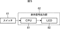
図5は、指示ペン14の第2の構成例を示している。
[Second Configuration Example of Pointer Pen 14]
FIG. 5 shows a second configuration example of the pointing
指示ペン14は、赤外信号出力部62として、CPU81とLED82を備える。
The pointing
CPU81は、スイッチ61のオン状態およびオフ状態を検出し、それぞれの状態に応じてLED82の点灯時間と消灯時間のDuty比(比率)を切り替える制御を行う。LED82は、CPU81の制御に応じて一定レベルの赤外光を出力する。
The
図6を参照して詳細を説明する。CPU81は、スイッチ61がオフ状態のときには、図6Aに示されるように、点灯時間よりも消灯時間の方が長くなるようなDuty比となるように、LED82の点灯を制御する。一方、スイッチ61がオン状態のときには、図6Bに示されるように、点灯時間よりも消灯時間の方が短くなるようなDuty比となるように、LED82の点灯を制御する。
Details will be described with reference to FIG. When the
IRカメラ13の撮像部51で検出される信号レベルは点灯時間の積算値に比例するため、このようにLED82の点灯時間と消灯時間のDuty比を制御することで、弱レベルと強レベルの2種類の出力が可能である。
Since the signal level detected by the
なお、図6の例では、点灯時間と消灯時間の大小関係がオン状態とオフ状態で逆転しているが、必ずしも逆転する必要はなく、オン状態のときの点灯時間が、オフ状態よりも長くなっていればよい。 In the example of FIG. 6, the magnitude relationship between the lighting time and the lighting time is reversed between the on state and the off state, but it is not always necessary to reverse, and the lighting time in the on state is longer than the off state. It only has to be.
以上では、指示ペン14の強レベルと弱レベルの2種類の赤外光を出力させるための2つの構成例について説明したが、この例に限定されず、強レベルと弱レベルの2種類の赤外光を出力するものであれば、その他の構成例を採用してもよい。
In the above, two configuration examples for outputting two types of infrared light of the strong level and the weak level of the pointing
[指示ペン14の動作]
図7は、指示ペン14の処理(動作)を説明するフローチャートである。
[Operation of the pointing pen 14]
FIG. 7 is a flowchart for explaining the processing (operation) of the pointing
初めに、ステップS1において、指示ペン14は、スイッチ61がオンであるかを判定する。
First, in step S1, the pointing
ステップS1で、スイッチ61がオンではない(オフである)と判定された場合、処理はステップS2に進み、指示ペン14は、弱レベルの赤外光を出力する。
When it is determined in step S1 that the
一方、ステップS1で、スイッチ61がオンであると判定された場合、処理はステップS3に進み、指示ペン14は、強レベルの赤外光を出力する。
On the other hand, if it is determined in step S1 that the
ステップS2またはS3の後、処理はステップS1に戻り、指示ペン14の電源がオフされるまで、上述したステップS1ないしS3の処理が繰り返される。
After step S2 or S3, the process returns to step S1, and the above-described steps S1 to S3 are repeated until the power of the pointing
[キャリブレーションモードの説明]
次に、図8を参照して、キャリブレーションモードについて説明する。
[Description of calibration mode]
Next, the calibration mode will be described with reference to FIG.
PC11で起動されたプレゼンテーション用のアプリケーションにおいて、キャリブレーションモードが実行されると、図8に示される画像の画像信号がPC11からプロジェクタ12に供給され、プロジェクタ12は、図8の画像をスクリーン15に投射する。
When the calibration mode is executed in the presentation application activated on the
図8は、プロジェクタ12の投射範囲(表示範囲)の垂直方向および水平方向に均等に3×3の9か所の丸(○)が表示された画像である。
FIG. 8 is an image in which nine circles (◯) of 3 × 3 are displayed evenly in the vertical and horizontal directions of the projection range (display range) of the
この画像の表示に先立って、または、表示とともに、プレゼンテーション用のアプリケーションでは、「9か所の目印に順番に指示ペン14でタッチして下さい。」等のメッセージが音声出力または画像表示される。なお、9か所の目印をタッチする順番は、予め決められているか、事前に説明されることによりユーザが認識しているものとする。
Prior to or along with the display of this image, in the application for presentation, a message such as “Please touch the nine markers in order with the pointing
PC11の指示位置補正部33は、ユーザが目印をタッチしたときに供給されるクリック情報(に含まれるクリック位置)を、表示画像の目印に対応させることで、スクリーン15に表示される画像と画像表示部31に表示される画像の位置関係を補正する。
The indication
一方、IRカメラ13は、キャリブレーションモードにおいて、指示ペン14の赤外光の弱レベルと強レベルの2種類の信号レベルを判別する閾値を決定する閾値決定処理を実行する。
On the other hand, in the calibration mode, the
図9は、PC11からキャリブレーションモードが通知されたときに実行される、IRカメラ13が行う閾値決定処理のフローチャートである。
FIG. 9 is a flowchart of threshold value determination processing performed by the
初めに、ステップS11において、撮像部51は、指示ペン14が発する赤外光の受光を開始する。即ち、撮像部51は、撮像素子が受光して得られる撮像信号を信号処理部52に供給する。
First, in step S <b> 11, the
ステップS12において、信号処理部52は、撮像部51から供給される撮像信号に基づいて、指示ペン14の赤外光の信号レベルを算出し、算出された信号レベルが弱レベルの信号であるかを判定する。ここで、弱レベルと強レベルとして取得され得る出力レベルの範囲は既知であるものとする。信号処理部52は、算出された信号レベルが弱レベルと強レベルそれぞれのどちらの範囲に含まれるかに応じて、算出された信号レベルが弱レベルの信号であるかを判定する。
In step S12, the
キャリブレーションモードでは、図8を参照して説明したように、ユーザは、スクリーン15に表示された目印を順番に指示ペン14でタッチする作業を行う。ユーザが指示ペン14で目印にタッチしたときには、指示ペン14のスイッチ61がオンとなり、強レベルの赤外光が信号処理部52で取得される。一方、ユーザが指示ペン14で目印にタッチしていない状況では、弱レベルの赤外光が信号処理部52で取得される。
In the calibration mode, as described with reference to FIG. 8, the user touches the marks displayed on the
ステップS12で、算出された信号レベルが弱レベルの信号であると判定された場合、処理はステップS13に進み、信号処理部52は、算出された信号レベルを弱レベルデータとして内部の一時メモリに記憶(蓄積)する。
If it is determined in step S12 that the calculated signal level is a weak signal, the process proceeds to step S13, and the
一方、ステップS12で、算出された信号レベルが強レベルの信号であると判定された場合、処理はステップS14に進み、信号処理部52は、撮像信号に基づいて算出された、指示ペン14の赤外光の受光位置のクリック情報を、プロジェクタ12を介してPC11に出力する。
On the other hand, when it is determined in step S12 that the calculated signal level is a high level signal, the process proceeds to step S14, and the
そして、ステップS15において、信号処理部52は、算出された信号レベルを強レベルデータとして内部の一時メモリに記憶(蓄積)する。
In step S15, the
ステップS13またはS15の処理後、ステップS16において、信号処理部52は、キャリブレーションモードが終了したか、すなわち、PC11からキャリブレーションモードを終了する旨の通知を受信したかを判定する。
After the process of step S13 or S15, in step S16, the
ステップS16で、キャリブレーションモードがまだ終了していないと判定された場合、処理はステップS12に戻り、上述したステップS12ないしS16の処理が繰り返される。 If it is determined in step S16 that the calibration mode has not ended yet, the process returns to step S12, and the processes of steps S12 to S16 described above are repeated.
一方、ステップS16で、キャリブレーションモードが終了したと判定された場合、処理はステップS17に進み、信号処理部52は、一時メモリに記憶しておいた弱レベルデータと強レベルデータそれぞれの平均値を算出する。
On the other hand, if it is determined in step S16 that the calibration mode has ended, the process proceeds to step S17, and the
そして、ステップS18において、信号処理部52は、算出された弱レベルデータと強レベルデータそれぞれの平均値から、弱レベルと強レベルを判別する閾値を決定し、閾値記憶部53に記憶させて、処理を終了する。例えば、弱レベルの平均値が「5」であり、強レベルの平均値が「10」である場合、両者の中間値の「7.5」が閾値に決定される。
In step S18, the
以上のように、IRカメラ13は、キャリブレーションモードとしてPC11側において画像の位置補正が行われるのに合わせて、受光した光信号の信号レベルを、弱レベルと強レベルのそれぞれに分類して蓄積する。そして、IRカメラ13は、蓄積された弱レベルのデータと強レベルのデータに基づいて、弱レベルと強レベルを判別する閾値を決定し、記憶する。
As described above, the
IRカメラ13が受光する赤外光の信号レベルは、プロジェクタ12の投射距離、即ち、プロジェクタ12に接続されて固定配置されているIRカメラ13とスクリーン15(指示ペン14)までの距離によって変化する。
The signal level of infrared light received by the
また、指示ペン14は、電源として乾電池や二次電池(バッテリ)を使用するのが一般的であり、電池の残容量によっても赤外光の出力レベルは変化する。
In general, the pointing
したがって、ユーザがプロジェクタ12の使用を開始するごとに行うキャリブレーションモードを利用して、IRカメラ13が図9の閾値決定処理を行うことで、その都度、最適な閾値を決定して、設定することができる。また、このとき、ユーザはキャリブレーションを行っていることは認識するが、閾値の設定については認識させることなく(自動で)行うことができる。
Therefore, the
[通常モードの説明]
次に、キャリブレーション終了後の通常モードの処理について説明する。
[Description of normal mode]
Next, the normal mode processing after the calibration is completed will be described.
図10は、通常モードにおいて、指示ペン14からの赤外光を受光するIRカメラ13等で行われる受光処理のフローチャートである。
FIG. 10 is a flowchart of a light receiving process performed by the
初めに、ステップS31において、IRカメラ13の撮像部51は、指示ペン14から出力される赤外光を受光する。撮像部51は、受光した結果得られる撮像信号を信号処理部52に供給する。
First, in step S31, the
ステップS32において、信号処理部52は、撮像部51から供給される撮像信号に基づいて、指示ペン14の赤外光の位置および信号レベルを算出する。
In step S <b> 32, the
ステップS33において、信号処理部52は、算出された信号レベルがキャリブレーションモードで決定された閾値以上であるか、すなわち、強レベルの赤外光を受光したかを判定する。
In step S <b> 33, the
ステップS33で、算出された信号レベルが閾値以上ではないと判定された場合、すなわち、弱レベルの赤外光を受光した場合、処理はステップS31に戻る。 If it is determined in step S33 that the calculated signal level is not greater than or equal to the threshold value, that is, if weak infrared light is received, the process returns to step S31.
一方、ステップS33で、算出された信号レベルが閾値以上であると判定された場合、すなわち、強レベルの赤外光を受光した場合、処理はステップS34に進む。そして、ステップS34において、信号処理部52は、受光した位置が、基準位置である直前の弱レベルの位置から所定の範囲内であるかを判定する。
On the other hand, if it is determined in step S33 that the calculated signal level is greater than or equal to the threshold value, that is, if a high level of infrared light is received, the process proceeds to step S34. In step S <b> 34, the
ステップS34で、受光した位置が基準位置から所定の範囲内ではないと判定された場合、処理はステップS31に戻る。 If it is determined in step S34 that the received light position is not within the predetermined range from the reference position, the process returns to step S31.
一方、ステップS34で、受光した位置が基準位置から所定の範囲内であると判定された場合、処理はステップS35に進む。 On the other hand, if it is determined in step S34 that the received light position is within a predetermined range from the reference position, the process proceeds to step S35.
ステップS35において、信号処理部52は、赤外光の受光位置でクリックされたことを示すクリック情報を、プロジェクタ12を介してPC11に送信する。
In step S <b> 35, the
そして、ステップS36において、PC11の指示位置補正部33は、プロジェクタ12を介してIRカメラ13から送信されてきたクリック情報を取得し、位置補正情報記憶部34に記憶されている補正値により、クリック情報の位置を補正する。そして、指示位置補正部33は、補正後のクリック情報を画像生成部32に供給する。
In step S 36, the indicated
さらに、ステップS37において、画像生成部32は、指示位置補正部33から供給された、スクリーン15に表示した画像上の所定の位置でクリックされたことを示すクリック情報に基づいて、プレゼンテーションの次の画像を表示するなどの所定の制御を行う。その結果、ディスプレイ11Dに表示された画像上におけるクリック操作と同一の操作を、ユーザは、スクリーン15に投射された画像上で行うことができる。
In step S37, the
なお、図10の処理は、一連の処理の流れを説明したものであり、実際には、IRカメラ13、プロジェクタ12、およびPC11のそれぞれで、各ステップの処理が繰り返し実行されている。
Note that the processing of FIG. 10 describes the flow of a series of processing, and actually, the processing of each step is repeatedly executed in each of the
以上のように、図1のプレゼンテーションシステム1では、指示ペン14は、弱レベルの赤外光を常時出力し、スイッチ61がオンされたときのみ、強レベルの赤外光を出力する。IRカメラ13は、指示ペン14が発する弱レベルの赤外光を捕捉し、弱レベルの受光位置の近傍で強レベルの赤外光を受光した場合のみ、クリック情報をPC11に出力する。
As described above, in the
これにより、IRカメラ13は、プロジェクタ12のリモートコントローラ12Rから、同一波長帯の赤外光が出力された場合であっても、指示ペン14の赤外光と誤ってクリック情報を出力することを防止することができる。すなわち、異なる目的で使用される同一波長帯の2つの信号を的確に区別することができる。
Thereby, the
従来、プロジェクタ12のリモートコントローラ12Rとインタラクティブペンを同時に使用しようとした場合には、リモートコントローラ12Rの赤外光で誤作動する場合があり、ユーザはリモートコントローラ12Rを未使用に設定変更する必要があった。しかし、本技術を適用することで、リモートコントローラ12Rとインタラクティブペンを同時に使用することができ、ユーザの利便性が向上する。また、弱レベルと強レベルの2種類の赤外光を受光する場合、弱レベルの受光位置の近傍の範囲のみを強レベルの赤外光の検出対象範囲とすることで、応答性を向上させることができる。
Conventionally, when trying to use the
[変形例]
本技術は、上述した実施の形態に限定されるものではなく、本技術の要旨を逸脱しない範囲において種々の変更が可能である。
[Modification]
The present technology is not limited to the above-described embodiments, and various modifications can be made without departing from the gist of the present technology.
例えば、上述した例では、指示ペン14はペン型の形状であって、先端部の接触(押圧)によってスイッチ61のオンオフ状態を変化させるようにした。しかし、指示ペン14に操作ボタンを設け、操作ボタンのオンオフ操作によってスイッチ61のオンオフ状態を変化させるようにしてもよい。
For example, in the above-described example, the pointing
また例えば、指示ペン14は、上述したようなペン型の形状に限らず、伸縮可能な指示棒型、指にはめるタイプのものなどの形状でもよく、2種類のレベルの赤外光の出力をスイッチに応じて切り替えられる光信号出力装置であればよい。
Further, for example, the pointing
さらに、上述した例では、光信号出力装置としての指示ペン14が出力する光信号は、780nmないし1000nmの波長帯の赤外光としたが、それ以外の波長帯、例えば、400nm以下の紫外光や、420nmないし480nm(青色)の可視光などでもよい。
Furthermore, in the above-described example, the optical signal output from the pointing
上述した例では、IRカメラ13は、プロジェクタ12に外付けされるものとして説明したが、プロジェクタ12に内蔵されるようにすることもできる。すなわち、プロジェクタ12が、その構成の一部としてIRカメラ13を備えるものでもよい。
In the above-described example, the
また、上述した例では、IRカメラ13は、強レベルの赤外光を受光した場合のみクリック情報をPC11に送信するようにしたが、IRカメラ13は常時赤外光を受光しているので、位置情報については常にPC11に送信するようにしてもよい。この場合、指示ペン14はマウスデバイスとしての動作が可能となる。IRカメラ13は、常時位置情報を出力するマウスデバイス型の動作と、クリックされたときの位置情報のみを出力するタブレットデバイス型の動作を、切り替えスイッチにより切り替えられるようにしてもよい。
Further, in the above-described example, the
図8を参照して説明したキャリブレーションモードでは、9か所の目印をタッチする例について説明したが、タッチする目印の個数は9か所以外の個数でもよい。また、タッチする順番については、各目印をタッチさせる順番に点滅させるなどの、タッチさせる目印の表示を他の箇所と異ならせることによりユーザに認知させるようにすることもできる。 In the calibration mode described with reference to FIG. 8, the example of touching nine marks has been described, but the number of touched marks may be other than nine. Moreover, about the order to touch, it can also make a user recognize by making the display of the mark to touch differ from another location, such as blinking in the order which touches each mark.
[コンピュータの構成例]
上述した一連の処理は、ハードウエアにより実行することもできるし、ソフトウエアにより実行することもできる。一連の処理をソフトウエアにより実行する場合には、そのソフトウエアを構成するプログラムが、コンピュータにインストールされる。ここで、コンピュータには、専用のハードウエアに組み込まれているコンピュータや、各種のプログラムをインストールすることで、各種の機能を実行することが可能な、例えば汎用のパーソナルコンピュータなどが含まれる。
[Computer configuration example]
The series of processes described above can be executed by hardware or can be executed by software. When a series of processing is executed by software, a program constituting the software is installed in the computer. Here, the computer includes, for example, a general-purpose personal computer capable of executing various functions by installing various programs by installing a computer incorporated in dedicated hardware.
図11は、上述した一連の処理をプログラムにより実行するコンピュータのハードウエアの構成例を示すブロック図である。 FIG. 11 is a block diagram illustrating a hardware configuration example of a computer that executes the above-described series of processing by a program.
コンピュータにおいて、CPU(Central Processing Unit)101,ROM(Read Only Memory)102,RAM(Random Access Memory)103は、バス104により相互に接続されている。
In a computer, a CPU (Central Processing Unit) 101, a ROM (Read Only Memory) 102, and a RAM (Random Access Memory) 103 are connected to each other via a
バス104には、さらに、入出力インタフェース105が接続されている。入出力インタフェース105には、入力部106、出力部107、記憶部108、通信部109、及びドライブ110が接続されている。
An input /
入力部106は、キーボード、マウス、マイクロホンなどよりなる。出力部107は、ディスプレイ、スピーカなどよりなる。記憶部108は、ハードディスクや不揮発性のメモリなどよりなる。通信部109は、ネットワークインタフェースなどよりなる。ドライブ110は、磁気ディスク、光ディスク、光磁気ディスク、或いは半導体メモリなどのリムーバブル記録媒体111を駆動する。
The
撮像部112は、図2の撮像部51に対応するものである。撮像部112は、投射範囲を撮像し、撮像して得られた撮像信号を、入出力インタフェース105を介してCPU101等に供給する。
The
以上のように構成されるコンピュータでは、CPU101が、例えば、記憶部108に記憶されているプログラムを、入出力インタフェース105及びバス104を介して、RAM103にロードして実行することにより、上述した一連の処理が行われる。
In the computer configured as described above, the
コンピュータでは、プログラムは、リムーバブル記録媒体111をドライブ110に装着することにより、入出力インタフェース105を介して、記憶部108にインストールすることができる。また、プログラムは、ローカルエリアネットワーク、インターネット、デジタル衛星放送といった、有線または無線の伝送媒体を介して、通信部109で受信し、記憶部108にインストールすることができる。その他、プログラムは、ROM102や記憶部108に、あらかじめインストールしておくことができる。
In the computer, the program can be installed in the
なお、本明細書において、フローチャートに記述されたステップは、記載された順序に沿って時系列的に行われる場合はもちろん、必ずしも時系列的に処理されなくとも、並列に、あるいは呼び出しが行われたとき等の必要なタイミングで実行されてもよい。 In the present specification, the steps described in the flowcharts are performed in parallel or in a call even if they are not necessarily processed in chronological order, as well as performed in chronological order according to the described order. It may be executed at a necessary timing such as when.
なお、本明細書において、システムとは、複数の装置により構成される装置全体を表すものである。 In the present specification, the term “system” represents the entire apparatus constituted by a plurality of apparatuses.
本技術は以下のような構成も取ることができる。
(1)
ユーザの操作に応じて、第1の状態または第2の状態のいずれかとなるスイッチと、
前記スイッチが前記第1の状態である場合には弱レベルの光信号を出力し、前記スイッチが前記第2の状態である場合には強レベルの光信号を出力する光信号出力部と
を備える光信号出力装置。
(2)
前記光信号出力部は、点灯時間と消灯時間の比率を変更することで、前記弱レベルまたは強レベルの2種類の光信号を出力する
前記(1)に記載の光信号出力装置。
(3)
前記光信号出力部は、前記強レベルの光信号として高輝度の光信号を出力する第1の発光部と、前記弱レベルの光信号として低輝度の光信号を出力する第2の発光部を備える
前記(1)に記載の光信号出力装置。
(4)
前記光信号は赤外光である
前記(1)ないし(3)のいずれかに記載の光信号出力装置。
(5)
弱レベルまたは強レベルの光信号を出力する光信号出力装置から出力された前記光信号を撮像する撮像部で得られた撮像信号に基づいて、所定の閾値以上の信号レベルの前記光信号が検出されたとき、前記光信号の位置情報を出力する光信号処理部
を備える信号処理装置。
(6)
前記光信号処理部は、前記撮像信号に基づいて、前記光信号の信号レベルを算出し、算出された前記光信号の信号レベルが前記所定の閾値以上であるかを判定し、前記所定の閾値以上であると判定したとき、前記光信号の位置情報を出力する
前記(5)に記載の信号処理装置。
(7)
前記光信号処理部は、さらに、検出された前記所定の閾値以上の信号レベルの前記光信号の位置が、前記所定の閾値以上の信号レベルの前記光信号を検出する直前の前記光信号の位置から所定の範囲内である場合に、前記光信号の位置情報を出力する
前記(5)または(6)に記載の信号処理装置。
(8)
前記光信号処理部は、さらに、前記光信号の信号レベルを、弱レベルと強レベルのそれぞれに分類して蓄積し、蓄積された弱レベルのデータと強レベルのデータに基づいて、前記所定の閾値を決定する
前記(5)ないし(7)のいずれかに記載の信号処理装置。
(9)
前記光信号は赤外光である
前記(5)ないし(8)のいずれかに記載の信号処理装置。
(10)
前記光信号処理部は、前記光信号の位置情報を、クリック情報の一部として出力する
前記(5)ないし(9)のいずれかに記載の信号処理装置。
(11)
弱レベルまたは強レベルの光信号を出力する光信号出力装置から出力された前記光信号を撮像する撮像部で得られた撮像信号に基づく信号処理を行う信号処理装置が、
所定の閾値以上の信号レベルの前記光信号が検出されたとき、前記光信号の位置情報を出力する
ステップを含む信号処理方法。
(12)
弱レベルまたは強レベルの光信号を出力する光信号出力装置から出力された前記光信号を撮像する撮像部で得られた撮像信号に基づく信号処理を行うコンピュータに、
所定の閾値以上の信号レベルの前記光信号が検出されたとき、前記光信号の位置情報を出力する
処理を実行させるためのプログラム。
(13)
弱レベルまたは強レベルの光信号を出力する光信号出力装置から出力された前記光信号を撮像する撮像部と、
前記撮像部で得られた撮像信号に基づいて、所定の閾値以上の信号レベルの前記光信号が検出されたとき、前記光信号の位置情報を出力する光信号処理部と
を備える撮像装置。
(14)
前記(13)に記載の撮像装置
を備えるプロジェクタ。
The present technology can also have the following configurations.
(1)
A switch that is in either the first state or the second state in response to a user operation;
An optical signal output unit that outputs a weak level optical signal when the switch is in the first state, and outputs a strong level optical signal when the switch is in the second state. Optical signal output device.
(2)
The optical signal output device according to (1), wherein the optical signal output unit outputs the two types of optical signals of the weak level or the strong level by changing a ratio between a lighting time and a lighting time.
(3)
The optical signal output unit includes: a first light emitting unit that outputs a high luminance optical signal as the strong level optical signal; and a second light emitting unit that outputs a low luminance optical signal as the weak level optical signal. The optical signal output device according to (1).
(4)
The optical signal output device according to any one of (1) to (3), wherein the optical signal is infrared light.
(5)
The optical signal having a signal level equal to or higher than a predetermined threshold is detected based on an imaging signal obtained by an imaging unit that images the optical signal output from the optical signal output device that outputs an optical signal of a weak level or a strong level. A signal processing device comprising: an optical signal processing unit that outputs position information of the optical signal when the optical signal is received.
(6)
The optical signal processing unit calculates a signal level of the optical signal based on the imaging signal, determines whether the calculated signal level of the optical signal is equal to or higher than the predetermined threshold, and the predetermined threshold The signal processing device according to (5), wherein when it is determined as above, position information of the optical signal is output.
(7)
The optical signal processing unit further detects the position of the optical signal immediately before the detected optical signal having a signal level equal to or higher than the predetermined threshold is detected. The signal processing device according to (5) or (6), wherein the position information of the optical signal is output when the signal is within a predetermined range.
(8)
The optical signal processing unit further categorizes and stores the signal level of the optical signal into a weak level and a strong level, and based on the stored weak level data and strong level data, The signal processing device according to any one of (5) to (7), wherein a threshold value is determined.
(9)
The signal processing device according to any one of (5) to (8), wherein the optical signal is infrared light.
(10)
The signal processing device according to any one of (5) to (9), wherein the optical signal processing unit outputs position information of the optical signal as part of click information.
(11)
A signal processing device that performs signal processing based on an imaging signal obtained by an imaging unit that images the optical signal output from the optical signal output device that outputs an optical signal of a weak level or a strong level,
A signal processing method including a step of outputting position information of the optical signal when the optical signal having a signal level equal to or higher than a predetermined threshold is detected.
(12)
A computer that performs signal processing based on an imaging signal obtained by an imaging unit that images the optical signal output from the optical signal output device that outputs an optical signal of a weak level or a strong level,
A program for executing a process of outputting position information of the optical signal when the optical signal having a signal level equal to or higher than a predetermined threshold is detected.
(13)
An imaging unit that images the optical signal output from the optical signal output device that outputs an optical signal of a weak level or a strong level;
An imaging apparatus comprising: an optical signal processing unit that outputs position information of the optical signal when the optical signal having a signal level equal to or higher than a predetermined threshold is detected based on an imaging signal obtained by the imaging unit.
(14)
A projector comprising the imaging device according to (13).
1 プレゼンテーションシステム, 12 プロジェクタ, 13 IRカメラ, 14 指示ペン, 51 撮像部, 52 信号処理部, 53 閾値記憶部, 61 スイッチ, 62 赤外信号出力部, 71a 高輝度LED, 71b 低輝度LED, 81 CPU, 82 LED 1 Presentation System, 12 Projector, 13 IR Camera, 14 Pointer Pen, 51 Imaging Unit, 52 Signal Processing Unit, 53 Threshold Memory Unit, 61 Switch, 62 Infrared Signal Output Unit, 71a High Brightness LED, 71b Low Brightness LED, 81 CPU, 82 LED
Claims (15)
前記スイッチが前記第1の状態である場合には第1レベルの光信号を出力し、前記スイッチが前記第2の状態である場合には前記第1レベルとは異なる第2レベルの光信号を出力する光信号出力部と
を備える光信号出力装置。 Provided at an end portion of the casing, a first state, and becomes the second state by contact with the object switch when not in contact with the object,
When the switch is in the first state, it outputs a first level optical signal, and when the switch is in the second state, it outputs a second level optical signal different from the first level. An optical signal output device comprising: an optical signal output unit for outputting.
請求項1に記載の光信号出力装置。 The optical signal output device according to claim 1.
請求項1に記載の光信号出力装置。 The optical signal output device according to claim 1, wherein the optical signal output unit outputs two types of optical signals of the first level or the second level by changing a ratio between a lighting time and a light-off time.
請求項1に記載の光信号出力装置。 The optical signal output unit outputs a first light emitting unit that outputs a high luminance optical signal as the second level optical signal, and a second light emitting unit that outputs a low luminance optical signal as the first level optical signal. The optical signal output device according to claim 1.
請求項1ないし4のいずれかに記載の光信号出力装置。 The optical signal is an optical signal output device according to any one of claims 1 is infrared light 4.
を備える信号処理装置。 The optical signal having a signal level equal to or higher than a predetermined threshold is detected based on an imaging signal obtained by an imaging unit that images the optical signal output from an optical signal output device that outputs optical signals having a plurality of signal levels. The detected position of the optical signal having a signal level equal to or higher than the predetermined threshold is within a predetermined range from the position of the optical signal immediately before detecting the optical signal having a signal level equal to or higher than the predetermined threshold. A signal processing device comprising: an optical signal processing unit that outputs information based on the detected optical signal.
前記光信号処理部は、前記光信号の信号レベルを、第1レベルと第2レベルのそれぞれに分類して蓄積し、蓄積された前記第1レベルに相当するデータと前記第2レベルに相当するデータに基づいて、前記所定の閾値を決定する
信号処理装置。 The optical signal having a signal level equal to or higher than a predetermined threshold is detected based on an imaging signal obtained by an imaging unit that images the optical signal output from an optical signal output device that outputs optical signals having a plurality of signal levels. An optical signal processing unit that outputs information based on the detected optical signal,
The optical signal processing unit classifies and stores the signal level of the optical signal into a first level and a second level, and corresponds to the stored data corresponding to the first level and the second level. The predetermined threshold is determined based on the data
Signal processing device .
請求項6または7に記載の信号処理装置。 The signal processing apparatus according to claim 6 , wherein the optical signal processing unit outputs position information of the optical signal as information based on the detected optical signal .
請求項6ないし8のいずれかに記載の信号処理装置。 The signal processing apparatus according to claim 6 , wherein the optical signal is infrared light.
請求項8に記載の信号処理装置。 The signal processing device according to claim 8 , wherein the optical signal processing unit outputs position information of the optical signal as part of click information.
所定の閾値以上の信号レベルの前記光信号が検出され、検出された前記所定の閾値以上の信号レベルの前記光信号の位置が、前記所定の閾値以上の信号レベルの前記光信号を検出する直前の前記光信号の位置から所定の範囲内である場合に、検出された前記光信号に基づく情報を出力する
ステップを含む信号処理方法。 A signal processing device that performs signal processing based on an imaging signal obtained by an imaging unit that images the optical signal output from an optical signal output device that outputs optical signals of a plurality of signal levels,
The optical signal having a signal level equal to or higher than a predetermined threshold is detected, and the detected position of the optical signal having a signal level equal to or higher than the predetermined threshold is immediately before detecting the optical signal having a signal level equal to or higher than the predetermined threshold. And outputting information based on the detected optical signal when the optical signal is within a predetermined range from the position of the optical signal .
所定の閾値以上の信号レベルの前記光信号が検出され、検出された前記所定の閾値以上の信号レベルの前記光信号の位置が、前記所定の閾値以上の信号レベルの前記光信号を検出する直前の前記光信号の位置から所定の範囲内である場合に、検出された前記光信号に基づく情報を出力する
処理を実行させるためのプログラム。 To a computer that performs signal processing based on an imaging signal obtained by an imaging unit that images the optical signal output from an optical signal output device that outputs optical signals of a plurality of signal levels,
The optical signal having a signal level equal to or higher than a predetermined threshold is detected, and the detected position of the optical signal having a signal level equal to or higher than the predetermined threshold is immediately before detecting the optical signal having a signal level equal to or higher than the predetermined threshold. A program for executing a process of outputting information based on the detected optical signal when the optical signal is within a predetermined range from the position of the optical signal .
前記撮像部で得られた撮像信号に基づいて、所定の閾値以上の信号レベルの前記光信号が検出され、検出された前記所定の閾値以上の信号レベルの前記光信号の位置が、前記所定の閾値以上の信号レベルの前記光信号を検出する直前の前記光信号の位置から所定の範囲内である場合に、検出された前記光信号に基づく情報を出力する光信号処理部と
を備える撮像装置。 An imaging unit that images the optical signal output from the optical signal output device that outputs optical signals of a plurality of signal levels;
Based on the imaging signal obtained by the imaging unit, the optical signal having a signal level equal to or higher than a predetermined threshold is detected, and the detected position of the optical signal having a signal level equal to or higher than the predetermined threshold is determined by the predetermined signal. An optical signal processing unit that outputs information based on the detected optical signal when it is within a predetermined range from the position of the optical signal immediately before detecting the optical signal having a signal level equal to or higher than a threshold value. .
を備えるプロジェクタ。 A projector comprising the imaging device according to claim 13.
前記スイッチが前記第1の状態である場合には第1レベルの光信号を出力し、前記スイッチが前記第2の状態である場合には前記第1レベルとは異なる第2レベルの光信号を出力する光信号出力部と、 When the switch is in the first state, it outputs a first level optical signal, and when the switch is in the second state, it outputs a second level optical signal different from the first level. An optical signal output unit to output,
前記光信号出力部から出力された前記光信号を撮像する撮像部で得られた撮像信号に基づいて前記光信号が検出され、検出された前記光信号に基づく情報を出力する光信号処理部と An optical signal processing unit that detects the optical signal based on an imaging signal obtained by an imaging unit that images the optical signal output from the optical signal output unit, and outputs information based on the detected optical signal;
を備える信号処理システム。 A signal processing system comprising:
Priority Applications (6)
| Application Number | Priority Date | Filing Date | Title |
|---|---|---|---|
| JP2011064051A JP5796733B2 (en) | 2011-03-23 | 2011-03-23 | Optical signal output device, signal processing device, signal processing method, signal processing system, imaging device, projector, and program |
| US13/415,053 US9594460B2 (en) | 2011-03-23 | 2012-03-08 | Optical signal output apparatus, signal processing apparatus, signal processing method, imaging apparatus, and projector |
| CN201210079171.9A CN102722268B (en) | 2011-03-23 | 2012-03-16 | Optical signalling output, processing unit and method and imaging device and projector |
| CN201710052255.6A CN106843530A (en) | 2011-03-23 | 2012-03-16 | Optical signalling output, processing unit, method and system and imaging device |
| US15/402,289 US9823783B2 (en) | 2011-03-23 | 2017-01-10 | Optical signal output apparatus, signal processing apparatus, signal processing method, imaging apparatus, and projector |
| US15/701,518 US10019118B2 (en) | 2011-03-23 | 2017-09-12 | Optical signal output apparatus, signal processing apparatus, signal processing method, imaging apparatus, and projector |
Applications Claiming Priority (1)
| Application Number | Priority Date | Filing Date | Title |
|---|---|---|---|
| JP2011064051A JP5796733B2 (en) | 2011-03-23 | 2011-03-23 | Optical signal output device, signal processing device, signal processing method, signal processing system, imaging device, projector, and program |
Related Child Applications (1)
| Application Number | Title | Priority Date | Filing Date |
|---|---|---|---|
| JP2015163803A Division JP6137247B2 (en) | 2015-08-21 | 2015-08-21 | Projector device and projector system |
Publications (3)
| Publication Number | Publication Date |
|---|---|
| JP2012198858A JP2012198858A (en) | 2012-10-18 |
| JP2012198858A5 JP2012198858A5 (en) | 2014-05-08 |
| JP5796733B2 true JP5796733B2 (en) | 2015-10-21 |
Family
ID=46877062
Family Applications (1)
| Application Number | Title | Priority Date | Filing Date |
|---|---|---|---|
| JP2011064051A Active JP5796733B2 (en) | 2011-03-23 | 2011-03-23 | Optical signal output device, signal processing device, signal processing method, signal processing system, imaging device, projector, and program |
Country Status (3)
| Country | Link |
|---|---|
| US (3) | US9594460B2 (en) |
| JP (1) | JP5796733B2 (en) |
| CN (2) | CN106843530A (en) |
Families Citing this family (12)
| Publication number | Priority date | Publication date | Assignee | Title |
|---|---|---|---|---|
| JP5796733B2 (en) * | 2011-03-23 | 2015-10-21 | ソニー株式会社 | Optical signal output device, signal processing device, signal processing method, signal processing system, imaging device, projector, and program |
| US9161419B2 (en) | 2012-07-02 | 2015-10-13 | International Business Machines Corporation | Intelligent and coordinated lighting of a lighting device |
| US20140049520A1 (en) * | 2012-08-14 | 2014-02-20 | Darius Lam | Mobile Interactive Projection System With Multi-Pen Input |
| JP6237028B2 (en) * | 2013-09-17 | 2017-11-29 | 株式会社リコー | Projection apparatus, projection method, and information processing system |
| JP6273775B2 (en) * | 2013-10-31 | 2018-02-07 | セイコーエプソン株式会社 | Light emitting device and image display system |
| JP2015148837A (en) * | 2014-02-04 | 2015-08-20 | 株式会社リコー | Coordinate input system, coordinate input method, information processing apparatus, and program |
| JP6492775B2 (en) * | 2015-03-03 | 2019-04-03 | セイコーエプソン株式会社 | Display device and display control method |
| JP7251094B2 (en) | 2018-10-22 | 2023-04-04 | セイコーエプソン株式会社 | POSITION DETECTION DEVICE, DISPLAY SYSTEM AND POSITION DETECTION METHOD |
| JP7251095B2 (en) | 2018-10-22 | 2023-04-04 | セイコーエプソン株式会社 | POSITION DETECTION DEVICE, DISPLAY DEVICE, DISPLAY SYSTEM AND POSITION DETECTION METHOD |
| JP7294350B2 (en) | 2018-11-01 | 2023-06-20 | ソニーグループ株式会社 | Information processing device, information processing method, and program |
| JP7310573B2 (en) | 2019-11-29 | 2023-07-19 | 株式会社リコー | Image projection device and image projection system |
| CN113194417B (en) * | 2021-04-30 | 2022-03-15 | 深圳市欢太科技有限公司 | Device connection method and device, computer device and storage medium |
Family Cites Families (24)
| Publication number | Priority date | Publication date | Assignee | Title |
|---|---|---|---|---|
| JPS5834849B2 (en) | 1976-11-26 | 1983-07-29 | 株式会社日立製作所 | data input device |
| JPS57203129A (en) | 1981-06-09 | 1982-12-13 | Sanyo Electric Co Ltd | Light pen and picture processing device using this light pen |
| US5502459A (en) * | 1989-11-07 | 1996-03-26 | Proxima Corporation | Optical auxiliary input arrangement and method of using same |
| JPH0437922A (en) | 1990-06-01 | 1992-02-07 | Fuji Xerox Co Ltd | Presentation device |
| JPH1063421A (en) | 1996-08-27 | 1998-03-06 | Hitachi Ltd | Coordinate input method for display, and display device |
| US6548967B1 (en) * | 1997-08-26 | 2003-04-15 | Color Kinetics, Inc. | Universal lighting network methods and systems |
| JP3862113B2 (en) * | 1997-09-08 | 2006-12-27 | ソニー株式会社 | Digitizer device |
| US7119788B2 (en) * | 1998-12-17 | 2006-10-10 | Sony Corporation | Image processing apparatus, image processing method, providing medium and presentation system |
| JP3994672B2 (en) * | 2000-03-31 | 2007-10-24 | セイコーエプソン株式会社 | Detection of indicated position using image processing |
| JP4613456B2 (en) | 2000-07-25 | 2011-01-19 | カシオ計算機株式会社 | Image display device, image display method, and program |
| JP2002073267A (en) | 2000-08-31 | 2002-03-12 | Canon Inc | Coordinate input device |
| JP2002229726A (en) | 2001-02-02 | 2002-08-16 | Canon Inc | Coordinate input device |
| US7039253B2 (en) * | 2001-07-24 | 2006-05-02 | Casio Computer Co., Ltd. | Image display device, image display method, program, and projection system |
| JP3755593B2 (en) | 2002-03-26 | 2006-03-15 | セイコーエプソン株式会社 | Projection-type image display system, projector, program, information storage medium, and image processing method |
| US6851831B2 (en) * | 2002-04-16 | 2005-02-08 | Gelcore Llc | Close packing LED assembly with versatile interconnect architecture |
| JP4590858B2 (en) * | 2003-11-18 | 2010-12-01 | 富士ゼロックス株式会社 | Writable projector and optical pointer |
| JP4469650B2 (en) * | 2004-04-22 | 2010-05-26 | 東芝モバイルディスプレイ株式会社 | Display device with light input function, display device, and light source device |
| JP2006243850A (en) | 2005-02-28 | 2006-09-14 | Toshiba Matsushita Display Technology Co Ltd | Flat display device, image input method therefor, and optical pen |
| JP4577612B2 (en) * | 2005-03-30 | 2010-11-10 | カシオ計算機株式会社 | Information display system and information display method |
| ES2624798T3 (en) * | 2007-07-16 | 2017-07-17 | Philips Lighting Holding B.V. | Management of a light source |
| DE102008011823B4 (en) * | 2008-02-29 | 2010-02-04 | Siemens Aktiengesellschaft | Method for flicker-free transmission of digital data in a free-space optical transmission system |
| WO2009119716A1 (en) | 2008-03-26 | 2009-10-01 | 日本電気株式会社 | Information processing system, information processing device, method, and program |
| WO2010101207A1 (en) | 2009-03-06 | 2010-09-10 | 日本電気株式会社 | Electronic pen system, positional variation measuring device, display method, and program |
| JP5796733B2 (en) * | 2011-03-23 | 2015-10-21 | ソニー株式会社 | Optical signal output device, signal processing device, signal processing method, signal processing system, imaging device, projector, and program |
-
2011
- 2011-03-23 JP JP2011064051A patent/JP5796733B2/en active Active
-
2012
- 2012-03-08 US US13/415,053 patent/US9594460B2/en active Active
- 2012-03-16 CN CN201710052255.6A patent/CN106843530A/en active Pending
- 2012-03-16 CN CN201210079171.9A patent/CN102722268B/en active Active
-
2017
- 2017-01-10 US US15/402,289 patent/US9823783B2/en active Active
- 2017-09-12 US US15/701,518 patent/US10019118B2/en active Active
Also Published As
| Publication number | Publication date |
|---|---|
| CN102722268A (en) | 2012-10-10 |
| US10019118B2 (en) | 2018-07-10 |
| US9823783B2 (en) | 2017-11-21 |
| CN102722268B (en) | 2017-06-09 |
| US20170123594A1 (en) | 2017-05-04 |
| US20120242880A1 (en) | 2012-09-27 |
| JP2012198858A (en) | 2012-10-18 |
| US20170371495A1 (en) | 2017-12-28 |
| US9594460B2 (en) | 2017-03-14 |
| CN106843530A (en) | 2017-06-13 |
Similar Documents
| Publication | Publication Date | Title |
|---|---|---|
| JP5796733B2 (en) | Optical signal output device, signal processing device, signal processing method, signal processing system, imaging device, projector, and program | |
| US9324295B2 (en) | Display device and method of controlling display device | |
| US9134814B2 (en) | Input device, display system and input method | |
| JP6307852B2 (en) | Image display device and method for controlling image display device | |
| CN105938410B (en) | Display device and control method of display device | |
| JP2012053584A (en) | Information display system and program | |
| JP2017009829A (en) | Image projection device, image projection system and video supply device | |
| JP6051828B2 (en) | Display device and control method of display device | |
| JP6137247B2 (en) | Projector device and projector system | |
| JP6273671B2 (en) | Projector, display system, and projector control method | |
| JP6300053B2 (en) | Projector device and projector system | |
| CN107203287B (en) | Electronic device and control method of electronic device | |
| JP2018132769A (en) | Image display device, and control method of image display device | |
| JP2020074089A (en) | Electronic device and control method of the same | |
| KR20160107684A (en) | Electric board system | |
| JP6111682B2 (en) | Display device and control method of display device | |
| JP6145963B2 (en) | Projector, display system, and projector control method | |
| JP2014120023A (en) | Display device, position detection device, and control method of display device | |
| JP2016103060A (en) | Image projection device, image projection system, and video supply device | |
| JP2016114626A (en) | Image display device | |
| JP6524741B2 (en) | Position detection device, display device, control method of position detection device, and control method of display device | |
| JP2017092849A (en) | Image display system | |
| JP2020191045A (en) | Indicator, display system, and operation method | |
| KR20160118738A (en) | Interactive electric board, laser pointer, portable terminal and position detecting method thereof | |
| JP2017090957A (en) | Image projection apparatus and image projection system |
Legal Events
| Date | Code | Title | Description |
|---|---|---|---|
| A521 | Request for written amendment filed |
Free format text: JAPANESE INTERMEDIATE CODE: A523 Effective date: 20140317 |
|
| A621 | Written request for application examination |
Free format text: JAPANESE INTERMEDIATE CODE: A621 Effective date: 20140317 |
|
| A977 | Report on retrieval |
Free format text: JAPANESE INTERMEDIATE CODE: A971007 Effective date: 20141127 |
|
| A131 | Notification of reasons for refusal |
Free format text: JAPANESE INTERMEDIATE CODE: A131 Effective date: 20141218 |
|
| A521 | Request for written amendment filed |
Free format text: JAPANESE INTERMEDIATE CODE: A523 Effective date: 20150213 |
|
| TRDD | Decision of grant or rejection written | ||
| A01 | Written decision to grant a patent or to grant a registration (utility model) |
Free format text: JAPANESE INTERMEDIATE CODE: A01 Effective date: 20150723 |
|
| A61 | First payment of annual fees (during grant procedure) |
Free format text: JAPANESE INTERMEDIATE CODE: A61 Effective date: 20150805 |
|
| R151 | Written notification of patent or utility model registration |
Ref document number: 5796733 Country of ref document: JP Free format text: JAPANESE INTERMEDIATE CODE: R151 |
|
| R250 | Receipt of annual fees |
Free format text: JAPANESE INTERMEDIATE CODE: R250 |
|
| R250 | Receipt of annual fees |
Free format text: JAPANESE INTERMEDIATE CODE: R250 |
|
| R250 | Receipt of annual fees |
Free format text: JAPANESE INTERMEDIATE CODE: R250 |