JP5786314B2 - Image forming system - Google Patents
Image forming system Download PDFInfo
- Publication number
- JP5786314B2 JP5786314B2 JP2010259642A JP2010259642A JP5786314B2 JP 5786314 B2 JP5786314 B2 JP 5786314B2 JP 2010259642 A JP2010259642 A JP 2010259642A JP 2010259642 A JP2010259642 A JP 2010259642A JP 5786314 B2 JP5786314 B2 JP 5786314B2
- Authority
- JP
- Japan
- Prior art keywords
- image forming
- display
- image
- unit
- data
- Prior art date
- Legal status (The legal status is an assumption and is not a legal conclusion. Google has not performed a legal analysis and makes no representation as to the accuracy of the status listed.)
- Active
Links
Images


Description
本発明は、画像形成システムに関する。 The present invention relates to an image forming system.
用紙に画像を形成するプリンタや複写機等の画像形成装置は、自装置の動作履歴情報としてのログデータを生成し保存している。そして、このログデータを解析することにより、故障や異常が発生した場合において、どのような動作中に故障が発生したのか、どの時点から異常が発生していたのか等が特定され、改善が図られている。 Image forming apparatuses such as printers and copiers that form images on paper generate and store log data as operation history information of the apparatus itself. By analyzing this log data, when a failure or abnormality occurs, it is specified what kind of operation the failure has occurred, from which point the abnormality has occurred, etc. It has been.
また、複数のプリンタやプリントサーバ等から構成されるプリントシステムでは、プリントサーバが、印刷データや印刷ログ(ジョブID、ジョブ名)等の情報を集積し、当該情報にタイムスタンプを対応付けてログ情報として記憶し、また、当該ログ情報を読み出して表示する機能を有し、更に、表示されたログ情報から任意のキーワードに該当するログ情報を抽出して表示したり、表示されたログ情報を指定された条件に従ってソートして表示したりする技術が開示されている(特許文献1参照)。 Also, in a printing system composed of a plurality of printers, print servers, etc., the print server accumulates information such as print data and print logs (job IDs, job names), and logs with the information associated with time stamps. It has a function of storing and reading out and displaying the log information, and further extracting and displaying log information corresponding to an arbitrary keyword from the displayed log information, and displaying the displayed log information. A technique of sorting and displaying according to specified conditions is disclosed (see Patent Document 1).
しかしながら、単独で画像形成処理を行なうことが可能な画像形成装置を用紙搬送経路上において直列的に複数連結して構成されたタンデム構成の画像形成システムでは、画像形成装置毎に自装置のログデータが保存されるため、単に個々の画像形成装置のログデータを取得するだけでは、画像形成システム全体のログデータをユーザが把握しづらいという問題がある。 However, in an image forming system having a tandem configuration in which a plurality of image forming apparatuses capable of independently performing image forming processing are connected in series on the paper transport path, log data of the own apparatus is provided for each image forming apparatus. Therefore, there is a problem that it is difficult for the user to grasp the log data of the entire image forming system simply by acquiring the log data of each image forming apparatus.
例えば、用紙の一方の面と他方の面とを異なる画像形成装置が画像形成処理を実行して1枚の用紙の両面に画像を形成する両面モードのジョブの場合には、当該ジョブのログデータは、用紙面毎に各画像形成装置に分かれて保存されることとなる。このジョブのログデータをジョブ開始から終了まで時系列で確認したい場合には、各画像形成装置のログデータをユーザが統合しなくてはならないという煩雑な作業が発生する。 For example, in the case of a job in a duplex mode in which an image forming apparatus that forms an image on both sides of one sheet by forming an image on both sides of one sheet by performing image forming processing on one side and the other side of the sheet, log data of the job Is stored separately in each image forming apparatus for each sheet surface. When it is desired to check the log data of this job in time series from the start to the end of the job, a troublesome work that requires the user to integrate the log data of each image forming apparatus occurs.
また、ある画像形成装置で発生したエラーが、画像形成システムを構成する複数の画像形成装置のうち、どの画像形成装置内の動作が原因で発生したものであるか等が把握しづらく、画像形成装置間の因果関係が把握しづらいものである。 In addition, it is difficult to grasp the error that occurred in a certain image forming apparatus due to the operation in which image forming apparatus among a plurality of image forming apparatuses constituting the image forming system. It is difficult to understand the causal relationship between devices.
本発明の課題は、上記問題に鑑みて、複数の画像形成装置が直列的に連結されたタンデム構成の画像形成システムにおいて、画像形成システム全体の動作履歴情報の把握容易性を高め、利便性を向上させることである。 In view of the above problems, an object of the present invention is to improve the ease of grasping the operation history information of the entire image forming system in a tandem image forming system in which a plurality of image forming apparatuses are connected in series. It is to improve.
請求項1に記載の発明は、複数の画像形成装置が直列に連結された直列タンデム構成により用紙の搬送経路の上流側の画像形成装置で用紙の一方の面に画像を形成し、下流側の画像形成装置で前記用紙の他方の面に画像を形成して一枚の用紙の画像形成を行う画像形成システムにおいて、前記画像形成装置それぞれは、自装置の識別情報が付加され、1ページの画像形成処理の開始や終了を含む動作履歴情報を蓄積する記憶部を有し、前記複数の画像形成装置のうち少なくとも一つの画像形成装置は、前記複数の画像形成装置それぞれの前記記憶部から前記動作履歴情報を取得し、当該取得した前記動作履歴情報をあわせて表示対象として、表示順番を連携動作の履歴が把握可能なように、時系列あるいはページ順に並び替えて一枚の用紙に対応する複数の画像形成装置の動作履歴として統合し、前記統合された動作履歴情報を、当該動作履歴情報毎に付加された前記識別情報と共に表示するための表示信号を出力する制御部を備えること、を特徴とする。
また、請求項2に記載の発明は、請求項1に記載の画像形成システムにおいて、前記表示信号に基づき、前記統合された動作履歴情報を、当該動作履歴情報毎に付加された前記識別情報と共に表示する表示部を備えること、を特徴とする。
According to the first aspect of the present invention, an image is formed on one surface of a sheet by an image forming apparatus on the upstream side of the sheet conveyance path by a series tandem configuration in which a plurality of image forming apparatuses are connected in series. In an image forming system in which an image is formed on the other side of the sheet by the image forming apparatus to form an image on one sheet, each of the image forming apparatuses is added with identification information of its own apparatus , and one page image A storage unit that accumulates operation history information including start and end of the forming process, and at least one of the plurality of image forming apparatuses is configured to perform the operation from the storage unit of each of the plurality of image forming apparatuses. get the history information, as displayed in accordance with the operation history information that the acquired, as the history of the cooperative operation of the display order is possible to grasp, on a sheet of paper sorted in chronological order or the order of pages A control unit that integrates operation histories of a plurality of corresponding image forming apparatuses and outputs a display signal for displaying the integrated operation history information together with the identification information added for each operation history information; , it said.
According to a second aspect of the present invention, in the image forming system according to the first aspect, the integrated operation history information is combined with the identification information added for each operation history information based on the display signal. A display unit for displaying is provided.
請求項3に記載の発明は、請求項2に記載の画像形成システムにおいて、前記統合された動作履歴情報を前記表示部に表示する際、動作履歴情報の表示順番の種類の指示が入力される表示順番入力部を備え、前記制御部は、前記表示順番入力部から入力された前記表示順番の種類に応じて前記動作履歴情報を並べ替えて統合すること、を特徴とする。
The invention of
請求項4に記載の発明は、請求項2又は3に記載の画像形成システムにおいて、前記表示部は、前記複数の画像形成装置のうち少なくともいずれか一つに設けられていること、を特徴とする。 According to a fourth aspect of the present invention, in the image forming system according to the second or third aspect , the display unit is provided in at least one of the plurality of image forming apparatuses. To do.
請求項5に記載の発明は、請求項2から4のいずれか一項に記載の画像形成システムにおいて、前記表示部は、前記複数の画像形成装置のうち少なくともいずれか一つの画像形成装置とネットワークを介して通信可能に接続されていること、を特徴とする。 According to a fifth aspect of the present invention, in the image forming system according to any one of the second to fourth aspects, the display unit is connected to at least one of the plurality of image forming apparatuses and a network. It is connected so that communication is possible via this.
請求項6に記載の発明は、請求項2から5のいずれか一項に記載の画像形成システムにおいて、前記画像形成装置それぞれの動作履歴情報を個別に表示させる、又は、統合して表示させるか否かの選択指示が入力される表示選択入力部を備え、前記制御部は、前記表示選択入力部に入力された選択指示に応じて、前記画像形成装置それぞれの動作履歴情報を個別に前記表示部に表示させる、又は、統合して前記表示部に表示させること、を特徴とする。 According to a sixth aspect of the present invention, in the image forming system according to any one of the second to fifth aspects, whether the operation history information of each of the image forming apparatuses is individually displayed or integratedly displayed. A display selection input unit for inputting an instruction to select whether or not, and the control unit individually displays the operation history information of each of the image forming apparatuses according to the selection instruction input to the display selection input unit. Displayed on the display unit or integrated and displayed on the display unit.
本発明によれば、複数の画像形成装置が直列的に連結されたタンデム構成の画像形成システムにおいて、統合されて表示される動作履歴情報には、画像形成装置の識別情報が付加されているため、画像形成システム全体の動作履歴情報の把握容易性を高めることができ、利便性を向上させることができる。 According to the present invention, in the image forming system having a tandem configuration in which a plurality of image forming apparatuses are connected in series, the identification information of the image forming apparatus is added to the operation history information displayed in an integrated manner. The ease of grasping the operation history information of the entire image forming system can be improved, and the convenience can be improved.
以下、図を参照して本発明の実施の形態を詳細に説明する。
まず、構成を説明する。
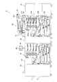
図1に、本実施の形態における画像形成システム1の概略構成図を示す。
図1に示すように、画像形成システム1は、用紙の搬送経路の上流側から、給紙装置10、第1画像形成装置20、反転装置30、第2画像形成装置40、後処理装置50等が直列的に連結された直列タンデム構成となっている。
Hereinafter, embodiments of the present invention will be described in detail with reference to the drawings.
First, the configuration will be described.
FIG. 1 shows a schematic configuration diagram of an
As shown in FIG. 1, the
本実施の形態における画像形成システムでは、用紙の両面に画像を形成する両面モードのジョブを実行する場合には、第1画像形成装置20が稼動することによって用紙の一方の面(例えば、表面)に画像を形成し、第2画像形成装置40が稼動することによって用紙の他方の面(例えば、裏面)に画像を形成する。また、用紙の片面に画像を形成する片面モードのジョブを実行する場合には、第2画像形成装置40が稼動することによって用紙の片面に画像を形成する。
In the image forming system according to the present embodiment, when executing a duplex mode job for forming an image on both sides of a sheet, the first
給紙装置10は、PFU(Paper Feed Unit)と称されるものであり、複数の給紙トレイや、給紙ローラ、分離ローラ、給紙/分離ゴム、送り出しローラ等からなる給紙手段等を備える。各給紙トレイには、用紙の種類(紙種、坪量、用紙サイズ等)毎に予め識別された用紙が格納されており、給紙トレイに格納されている用紙の最上部から一枚ずつ給紙手段により用紙が第1画像形成装置20の用紙搬送部へ搬送される。
The
第1画像形成装置20は、原稿から画像を読み取り、読み取った画像を用紙に画像形成したり、外部装置等からPDL(Page Description Language)形式やTiff形式等のページ記述言語形式のプリントデータ、及び、当該プリントデータに対する各種出力指示が設定されたプリント設定データを受信し、受信したプリントデータ及びプリント設定データ等に基づいて画像を用紙上に画像形成する。第1画像形成装置20は、画像読取部21、操作表示部22、プリント部23等を備えて構成される。
The first
画像読取部21は、ADF(Auto Document Feeder)と称される自動原稿送り部と読取部とを備え、操作表示部22により受け付けられた設定情報に基づいて原稿の画像を読み取り、アナログ信号の画像データを生成する。自動原稿送り部の原稿トレイに載置された原稿は、読取個所であるコンタクトガラスに搬送され、光学系により原稿の片面又は両面の画像が読み取られ、CCD(Charge Coupled Device)211により原稿の画像が読み取られる。ここで、画像とは、図形や写真等の画像データに限らず、文字や記号等のテキストデータ等も含む意である。
The
操作表示部22は、LCD(Liquid Crystal Display)221、LCD221を覆うように設けられたタッチパネル、各種スイッチやボタン、テンキー、操作キー群等から構成される。操作表示部22は、ユーザからの指示を受け付けその操作信号を制御部250に出力し、また、制御部250から入力される表示信号に従って、各種操作指示や設定情報を入力するための各種画面や各種処理結果等を表示する。
The
プリント部23は、電子写真方式の画像形成処理を行うものであり、給紙部231、用紙搬送部232、各色の画像形成部233、定着部234等のプリント出力に係る各部を備えて構成される。
なお、本実施の形態のプリント部23では、電子写真方式を適用した例を説明するが、これに限らず、インクジェット方式、熱昇華方式等、他のプリント方式を適用することとしてもよい。
The
In addition, although the example which applied the electrophotographic system is demonstrated in the
給紙部231は、複数の給紙トレイと給紙トレイ毎に設けられた給紙ローラ、分離ローラ、給紙/分離ゴム、送り出しローラ等からなる給紙手段を備える。各給紙トレイには、用紙の種類(紙種、坪量、用紙サイズ等)毎に予め識別された用紙が格納されており、給紙トレイに格納されている用紙の最上部から一枚ずつ給紙手段により用紙搬送部に向けて搬送される。
The
用紙搬送部232は、給紙装置10又は給紙部231から搬送された用紙を、複数の中間ローラ、レジストローラ等を経る画像形成部233への用紙搬送経路上に用紙を搬送し、画像形成部233の転写装置へと搬送する。
また、用紙搬送部232は、反転搬送部232aを備える。反転搬送部232aは、定着部234から排出された用紙を、反転ローラ等によりスイッチバックして表裏反転させ、反転装置30又は二次転写位置へ搬送する。
The
The
画像形成部233は、感光体ドラム、帯電装置、露光装置、現像装置、一次転写ローラ、クリーニング装置等を備え、印刷画像データに基づき用紙上に画像が形成された出力物を生成する。第1画像形成装置20がカラー画像を形成するものである場合には、画像形成部233が色毎に設けられる。
The
イエロー(Y)の画像を形成する画像形成部233yでは、帯電装置により帯電された感光体ドラムの表面に、露光装置からイエロー(Y)の印刷画像データに応じた光が照射され静電潜像が書き込まれる。そして、静電潜像が書き込まれた感光体ドラムの表面に、帯電したイエロー(Y)のトナーが現像装置により付着されて静電潜像が現像される。現像装置により感光体ドラム上に付着したトナーは、感光体ドラムが一定速度で回転されることにより、一次転写ローラが配置された一次転写位置で中間転写ベルト233aに転写される。中間転写ベルト233aにトナーが転写された後、クリーニング装置により、感光体ドラムの表面の残留電荷や残留トナー等が除去され、除去されたトナー等はトナー回収箱へ回収される。
In the
同様に、マゼンタ(M)、シアン(C)、ブラック(K)の各色の画像を形成する画像形成部233m、233c、233kは、感光体ドラムの周囲に配置された帯電装置、露光装置、現像装置、一次転写ローラ、クリーニング装置等を備え、マゼンタ(M)、シアン(C)、ブラック(K)のトナー像をそれぞれ形成する。
Similarly,
中間転写ベルト233aに転写された各色のトナー像は、二次転写ローラが配置された二次転写位置で用紙に一括転写される。
The toner images of each color transferred to the
定着部234は、定着ヒータ、定着ローラ、定着外部加熱部等から構成され、用紙に転写されたトナー像を熱定着する。
The fixing
定着部234により定着処理された用紙は、排紙ローラ等により反転装置30に搬送される、又は、用紙搬送部232の反転搬送部232aにより反転されて再度二次転写位置に搬送される。
The paper fixed by the fixing
反転装置30は、第1画像形成装置20と第2画像形成装置40との間に設置されており、第1画像形成装置20から搬送された用紙を、第2画像形成装置40へと搬送する。反転装置30は、反転ローラ等を有する用紙反転部と、複数枚の用紙をスタックするスタック部とを備えている。第2画像形成装置40へ搬送する用紙が、表裏を反転させる必要がある場合には、第1画像形成装置20から搬送された用紙は、用紙反転部によりスイッチバックされることにより表裏反転され、第2画像形成装置40へと搬送される。
なお、第1画像形成装置20から第2画像形成装置40へ搬送される用紙の反転を、第1画像形成装置20内の用紙反転部が行う場合には、反転装置30を画像形成システム1に設けなくてもよい。
The reversing
When the sheet reversing unit in the first
第2画像形成装置40は、操作表示部42、プリント部43等を備えて構成され、画像を用紙上に画像形成する。
なお、第2画像形成装置40が備える操作表示部42、プリント部43は、第1画像形成装置20が備える操作表示部22、プリント部23と同様の構成であるため、説明は省略する。
The second
Note that the
後処理装置50は、反転ユニット、ソートユニット、ステイプルユニット、パンチユニット、折ユニット、冊子ユニット等の各種後処理ユニットと、排紙トレイ等を備え、第2画像形成装置40から搬送された用紙に対して各種後処理を施し、後処理が施された用紙を排紙トレイに排出する。
The
図2に、本実施の形態における第1画像形成装置20の概略構成図を示す。
図2に示すように、第1画像形成装置20は、画像読取部21、操作表示部22、プリント部23、コントローラ24、画像制御基板25、HDD(Hard Disk Drive)26、通信部27等を備えて構成されている。第1画像形成装置20は、コントローラ24のLANIF(Local Area Network InterFace)244を介してネットワーク3上の外部装置2と相互にデータが送受信可能に接続されている。
FIG. 2 is a schematic configuration diagram of the first
As shown in FIG. 2, the first
画像読取部21は、上述した自動原稿送り部及び読取部と、画像読取制御部210とを備える。画像読取制御部210は、制御部250からの指示に基づいて自動原稿送り部及び読取部等を制御して、複数の原稿の画像を読み取るスキャナ機能を実現させる。画像読取部21により読み取られたアナログ信号の画像データは、読取処理部253に出力され、読取処理部253においてA/D変換され各種画像処理が施される。
The
操作表示部22は、上述したLCD221やタッチパネル等と、操作表示制御部220とを備える。操作表示制御部220は、制御部250から入力される表示信号に従って、各種設定条件を入力するための各種画面や各種処理結果等をLCDに表示させる。また、操作表示制御部220は、各種スイッチやボタン、テンキー、操作キー群又はタッチパネル等から入力される操作信号を制御部250に出力する。
The
プリント部23は、上述した給紙部231、用紙搬送部232、各色の画像形成部233、定着部234等のプリント出力に係る各部と、プリント制御部230とを備える。プリント制御部230は、制御部250からの指示に従って各色の画像形成部233等のプリント部23の各部の動作を制御し、書込処理部258から入力された印刷画像データに基づいて画像形成を行わせる。
The
コントローラ24は、ネットワーク3に接続される外部装置2等から画像形成システム1に入力されるデータの管理及び制御を行うものであり、外部装置2からプリント対象のデータ(プリントデータ及びプリント設定データ)を受信し、当該プリントデータを展開して生成した画像データとプリント設定データとを画像制御基板25へ送信する。
コントローラ24は、コントローラ制御部241、DRAM(Dynamic Random Access Memory)制御IC242、画像メモリ243、LANIF244等から構成される。
The
The
コントローラ制御部241は、コントローラ24各部の動作を統括的に制御し、LANIF244を介して外部装置2から入力されるプリントデータを展開してビットマップ形式の画像データの生成を行う。
The
DRAM制御IC242は、LANIF244により受信されたプリントデータのコントローラ制御部241への転送や、画像メモリ243に対する画像データ及びプリント設定データの書き込み/読み出しを制御する。また、DRAM制御IC242は、画像制御基板25のDRAM制御IC255とPCI(Peripheral Components Interconnect)バスで接続されており、コントローラ制御部241からの指示に従って、プリント対象の画像データ及びプリント設定データを画像メモリ243から読み出してDRAM制御IC255に出力する。
The
画像メモリ243は、DRAM等の揮発性のメモリにより構成され、受信したプリントデータ及びプリント設定データや、生成した画像データを一時的に記憶する。
The
LANIF244は、NIC(Network Interface Card)やモデム等のLAN等のネットワーク3に接続するための通信インターフェイスであり、外部装置2からプリントデータやプリント設定データを受信する受信部として機能する。受信されたプリントデータやプリント設定データは、DRAM制御IC242に出力される。
The
画像制御基板25は、制御部250、不揮発メモリ251、RAM(Random Access Memory)252、読取処理部253、圧縮IC254、DRAM制御IC255、画像メモリ256、伸長IC257、書込処理部258等を備える。
The
制御部250は、CPU(Central Processing Unit)等から構成され、不揮発メモリ251に格納されているシステムプログラム及び各種アプリケーションプログラムの中から指定されたプログラムを読み出してRAM252に展開し、RAM252に展開されたプログラムとの協働で、各種処理を実行し、第1画像形成装置20の各部を集中制御する。
The
また、制御部250は、不揮発メモリ251から本実施の形態に係るログデータ蓄積処理プログラム、ログデータ表示処理プログラム及び各種データとの協働により、ログデータ蓄積処理、ログデータ表示処理を実行する。
Further, the
ログデータ蓄積処理では、自装置の動作状態に係る情報である動作履歴情報(ログデータ)がHDD26に蓄積される。例えば、第2画像形成装置40と通信が行なわれログデータの蓄積開始タイミングの同期が取られた後、自装置の動作状態が変化したタイミングでログデータが取得される。そして、取得されたログデータは、当該自装置に予め設定された識別情報(装置ID)が付加されてHDD26内に蓄積される。
In the log data accumulation process, operation history information (log data), which is information related to the operation state of the own apparatus, is accumulated in the
ログデータとしては、ログデータが取得されたときの動作状態(Status)及び日時情報(タイムスタンプ)、ログデータが取得されたときに実行されているジョブの識別番号(ジョブID)及びページ番号、当該ジョブのドキュメント名、当該ジョブの実行を指示したユーザ名等を示すデータが含まれる。動作状態としては、画像形成開始,終了,停止,再開や、JAMの発生,復帰、トナー不足等のエラーなどが挙げられる。 The log data includes the operation status (Status) and date / time information (time stamp) when the log data is acquired, the identification number (job ID) and page number of the job being executed when the log data is acquired, Data indicating the document name of the job, the name of the user who instructed execution of the job, and the like are included. Examples of the operation state include start, end, stop, and restart of image formation, occurrence of JAM, return, error such as toner shortage, and the like.
ログデータ表示処理では、画像形成システム1を構成する複数の画像形成装置のログデータが操作表示部22に表示される。詳しくは、ログデータ表示処理では、画像形成システム1を構成する複数の画像形成装置それぞれのHDDから(本実施の形態では、第1、2画像形成装置のHDDから)、装置IDが付加されているログデータが取得される。そして、当該複数の画像形成装置それぞれのログデータが操作表示部により入力された表示順番の種類に応じて並べ替えられて統合(マージ)され、当該統合されたログデータを示す画面が操作表示部22のLCD221に表示される。
In the log data display process, log data of a plurality of image forming apparatuses constituting the
なお、本実施の形態では、統合されたログデータの表示先として、操作表示部22のLCD221の場合を挙げて説明するが、これに限らず、ネットワーク3を介して接続された外部装置2に当該統合されたログデータを送信して外部装置2が備えるディスプレイ等の表示部に表示させてもよい。
In the present embodiment, the display destination of the integrated log data will be described using the
なお、ジョブとは、画像形成に関する一連の動作であり、例えば、所定ページの原稿からなる複写物を作成する場合には、所定ページの原稿の画像形成に関する一連の動作が1ジョブである。このジョブの動作を実行するためのデータがジョブデータである。
ジョブデータは、ジョブ情報とページ情報とを含む。
ジョブ情報は、全ページに共通する情報であり、例えば、ジョブのドキュメント名、ユーザ名、部数、出力モード、出力トレイ、応用機能、テストプリント有無、カラーモード、用紙種類等を含む。
ページ情報は、各ページの圧縮画像データと関連付けられており、関連付けられた圧縮画像データに係る情報である。例えば、ページ情報は、ページ番号、画像サイズ(縦、横)、画像向き、画像の幅、画像の回転角度、圧縮画像データの格納アドレス等を含む。
Note that a job is a series of operations related to image formation. For example, when a copy made of a document of a predetermined page is created, a series of operations related to image formation of a document of a predetermined page is one job. Data for executing this job operation is job data.
The job data includes job information and page information.
The job information is information common to all pages, and includes, for example, a job document name, a user name, the number of copies, an output mode, an output tray, an applied function, presence / absence of a test print, a color mode, a paper type, and the like.
The page information is associated with the compressed image data of each page, and is information related to the associated compressed image data. For example, the page information includes a page number, an image size (vertical and horizontal), an image orientation, an image width, an image rotation angle, a storage address for compressed image data, and the like.
不揮発メモリ251は、画像形成に係る各種処理プログラム及び各種データの他、本実施の形態に係るログデータ蓄積処理プログラムと、ログデータ表示処理プログラムと、各種プログラムで処理されたデータ等を記憶する。
In addition to various processing programs and various data related to image formation, the
RAM252は、制御部250により実行される各種プログラム及びこれらプログラムに係る各種データ等を一時的に記憶するワークエリアを形成する。
また、RAM252には、コントローラ24から入力された画像データ及びプリント設定データ、又は、画像読取部21から入力された画像データ及び当該画像データが取得される際に操作表示部22により設定された設定情報、に基づいて制御部250により生成されたジョブデータを一時的に記憶する。
The
The
読取処理部253は、画像読取部21から入力されるアナログ信号の画像データに対して、アナログ処理、A/D変換処理、シェーディング処理等の各種処理を施した後、デジタル信号の画像データを生成する。生成された画像データは、圧縮IC254に出力される。
The
圧縮IC254は、入力されたデジタル信号の画像データに圧縮処理を施してDRAM制御IC255に出力する。
The
DRAM制御IC255は、制御部250からの指示に従って、圧縮IC254による画像データの圧縮処理及び伸長IC257による圧縮画像データの伸長処理を制御するとともに、画像メモリ256への画像データの入出力制御を行う。
The
例えば、DRAM制御IC255は、画像読取部21により読み取られた画像データの保存指示が制御部250から入力されると、読取処理部253に入力された画像データの圧縮処理を圧縮IC254により実行させて、圧縮画像データを画像メモリ256の圧縮メモリ256aに記憶させる。また、DRAM制御IC255は、コントローラ24のDRAM制御IC242から画像データが入力されると、当該画像データの圧縮処理を圧縮IC254により実行させ、圧縮画像データを画像メモリ256の圧縮メモリ256aに記憶させる。
For example, when an instruction to save image data read by the
更に、DRAM制御IC255は、圧縮メモリ256aに記憶された圧縮画像データのプリント出力指示が制御部250から入力されると、圧縮メモリ256aから圧縮画像データを読み出し、伸長IC257により伸長処理を施してページメモリ256bに記憶させる。さらに、ページメモリ256bに記憶された画像データのプリント出力指示が入力されると、ページメモリ256bから画像データを読み出して書込処理部258に出力する。
Further, when the print control instruction for the compressed image data stored in the
画像メモリ256は、DRAM(Dynamic RAM)から構成される圧縮メモリ256aとページメモリ256bとを備える。圧縮メモリ256aは、圧縮画像データを記憶するためのメモリであり、ページメモリ256bは、プリント出力用の画像データを一時的に記憶、又は、コントローラからの受信データを圧縮前に一時的に記憶するためのメモリである。
The
伸長IC257は、圧縮画像データに伸長処理を施す。
The
書込処理部258は、DRAM制御IC255から入力された画像データに基づいて、画像形成のための印刷画像データを生成し、プリント部23に出力する。
The
HDD26は、自装置の装置IDが付加されたログデータを蓄積する記憶部として機能する。
なお、本実施の形態では、ログデータを記憶する記憶媒体としてHDDを用いているが、これに限らず、不揮発性のメモリであればよい。
The
In this embodiment, an HDD is used as a storage medium for storing log data. However, the present invention is not limited to this, and any non-volatile memory may be used.
通信部27は、画像形成システム1を構成する各装置が接続されたネットワークに接続するための通信インターフェイスであり、各装置と各種データ送受信する。
The
図3に、本実施の形態における第2画像形成装置40の概略構成図を示す。
図3に示すように、第2画像形成装置40は、操作表示部42、プリント部43、コントローラ44、画像制御基板45、HDD46、通信部47等を備えて構成されている。
FIG. 3 shows a schematic configuration diagram of the second
As shown in FIG. 3, the second
操作表示部42、プリント部43、コントローラ44は、第1画像形成装置20の操作表示部22、プリント部23、コントローラ24と同様であるため、同一部分には同一符号を付し、説明は省略する。
Since the
画像制御基板45は、制御部450、不揮発メモリ451、RAM452、圧縮IC454、DRAM制御IC455、画像メモリ456、伸長IC457、書込処理部458等を備える。
The
制御部450は、CPU等から構成され、不揮発メモリ451に格納されているシステムプログラム及び各種アプリケーションプログラムの中から指定されたプログラムを読み出してRAM452に展開し、RAM452に展開されたプログラムとの協働で、各種処理を実行し、第2画像形成装置40の各部を集中制御する。
The
また、制御部450は、不揮発メモリ451から本実施の形態に係るログデータ蓄積処理プログラム及び各種データとの協働により、ログデータ蓄積処理を実行する。
なお、制御部450が実行するログデータ蓄積処理は、第1画像形成装置20の制御部250が実行するログデータ蓄積処理と同様であるため、説明は省略する。
Further, the
Note that the log data storage process executed by the
不揮発メモリ451は、画像形成に係る各種処理プログラム及び各種データの他、本実施の形態に係るログデータ蓄積処理プログラムと、各種プログラムで処理されたデータ等を記憶する。
The
RAM452は、制御部450により実行される各種プログラム及びこれらプログラムに係る各種データ等を一時的に記憶するワークエリアを形成する。
また、RAM452には、コントローラ44から入力された画像データ及びプリント設定データに基づいて制御部450により生成されたジョブデータを一時的に記憶する。
The
The
圧縮IC454は、入力されたデジタル信号の画像データに圧縮処理を施してDRAM制御IC455に出力する。
The
DRAM制御IC455は、制御部450からの指示に従って、圧縮IC454による画像データの圧縮処理及び伸長IC457による圧縮画像データの伸長処理を制御するとともに、画像メモリ456への画像データの入出力制御を行う。
The
例えば、DRAM制御IC455は、コントローラ44のDRAM制御IC242から画像データが入力されると、当該画像データの圧縮処理を圧縮IC454により実行させ、圧縮画像データを画像メモリ456の圧縮メモリ456aに記憶させる。
For example, when image data is input from the
更に、DRAM制御IC255は、圧縮メモリ456aに記憶された圧縮画像データのプリント出力指示が制御部450から入力されると、圧縮メモリ456aから圧縮画像データを読み出し、伸長IC457により伸長処理を施してページメモリ456bに記憶させる。さらに、ページメモリ456bに記憶された画像データのプリント出力指示が入力されると、ページメモリ456bから画像データを読み出して書込処理部458に出力する。
Furthermore, when a print output instruction for compressed image data stored in the
画像メモリ456は、DRAM(Dynamic RAM)から構成される圧縮メモリ456aとページメモリ456bとを備える。圧縮メモリ456aは、圧縮画像データを記憶するためのメモリであり、ページメモリ456bは、プリント出力用の画像データを一時的に記憶、又は、コントローラからの受信データを圧縮前に一時的に記憶するためのメモリである。
The
伸長IC457は、圧縮画像データに伸長処理を施す。
The
書込処理部458は、DRAM制御IC455から入力された画像データに基づいて、画像形成のための印刷画像データを生成し、プリント部23に出力する。
The
HDD46は、自装置の装置IDが付加されたログデータを蓄積する記憶部として機能する。
なお、本実施の形態では、ログデータを記憶する記憶媒体としてHDDを用いているが、これに限らず、不揮発性のメモリであればよい。
The
In this embodiment, an HDD is used as a storage medium for storing log data. However, the present invention is not limited to this, and any non-volatile memory may be used.
通信部47は、画像形成システム1を構成する各装置が接続されたネットワークに接続するための通信インターフェイスであり、各装置と各種データ送受信する。
The
次に、本実施の形態の動作を説明する。
図4に、本実施の形態におけるログデータ表示処理のフローチャートを示す。図4に示すログデータ表示処理は、制御部250と各部とが協働して実行される。
Next, the operation of the present embodiment will be described.
FIG. 4 shows a flowchart of log data display processing in the present embodiment. The log data display process shown in FIG. 4 is executed in cooperation between the
制御部250は、操作表示部22からログデータの表示要求を示す操作信号を受信したか否かを判別し(ステップS1)、ログデータの表示要求を示す操作信号を受信していない場合(ステップS1;NO)、ステップS1の処理に戻る。
The
ログデータの表示要求を示す操作信号を受信した場合(ステップS1;YES)、制御部250は、ログ表示形式選択画面を表示させる表示信号を操作表示部22へ送信し、LCD221上にログ表示形式選択画面を表示させる(ステップS2)。
When an operation signal indicating a log data display request is received (step S <b> 1; YES), the
図5に、ログ表示形式選択画面の例を示す。
図5に示すように、ログ表示形式選択画面G1には、メッセージ領域M1、個別表示ボタンB11、マージ表示ボタンB12等が設けられている。
メッセージ領域M1には、ログデータの表示形式をユーザに選択させるメッセージが示される。個別表示ボタンB11は、画像形成システム1を構成する複数の画像形成装置それぞれのログデータを画像形成装置毎に個別に表示させる個別形式の指示を受け付ける。マージ表示ボタンB12は、画像形成システム1を構成する複数の画像形成装置それぞれのログデータを統合して表示させるマージ形式の指示を受け付ける。
従って、ログ表示形式選択画面を表示する操作表示部22は、画像形成装置それぞれのログデータを個別に表示させる、又は、統合して表示させるか否かの選択指示が入力される表示選択入力部として機能する。
FIG. 5 shows an example of a log display format selection screen.
As shown in FIG. 5, the log display format selection screen G1 is provided with a message area M1, an individual display button B11, a merge display button B12, and the like.
In the message area M1, a message for allowing the user to select a display format of log data is shown. The individual display button B11 accepts an instruction in an individual format for individually displaying the log data of each of the plurality of image forming apparatuses constituting the
Accordingly, the
制御部250は、ログ表示形式選択画面において、マージ表示ボタンが選択されたか個別表示ボタンが選択されたかを判別することにより、選択された表示形式がマージ形式か個別形式かを判別する(ステップS3)。
The
選択された表示形式が個別形式である場合(ステップS3;個別)、制御部250は、自装置のHDD26からログデータを読み出し、読み出したログデータを示す画面を表示させる表示信号を操作表示部22へ送信し、LCD221上に自装置のログデータ画面を表示させる(ステップS4)。
When the selected display format is an individual format (step S3; individual), the
また、制御部250は、第2画像形成装置に対してログデータの取得要求を示す信号を送信し(ステップS5)、第2画像形成装置からログデータを受信したか否かを判別する(ステップS6)。
Further, the
第2画像形成装置の制御部450は、第1画像形成装置からログデータの取得要求を示す信号を受信すると、自装置のHDD46からログデータを読み出し、読み出したログデータを第1画像形成装置へ送信する。
When the
第2画像形成装置からログデータを受信していない場合(ステップS6;NO)、制御部250は、ステップS6の処理に戻る。第2画像形成装置からログデータを受信した場合(ステップS6;YES)、制御部250は、受信した第2画像形成装置のログデータを示す画面を表示させる表示信号を操作表示部22へ送信し、LCD221上に第2画像形成装置のログデータ画面を表示させ(ステップS7)、ログデータ表示処理を終了する。
When log data has not been received from the second image forming apparatus (step S6; NO), the
選択された表示形式がマージ形式である場合(ステップS3;マージ)、制御部250は、ログ表示種別選択画面を表示させる表示信号を操作表示部22へ送信し、LCD221上にログ表示種別選択画面を表示させ、ログ表示種別選択画面においてログデータの表示順序の種類の指示を取得する(ステップS8)。
When the selected display format is the merge format (step S3; merge), the
図6に、ログ表示種別選択画面の例を示す。
図6に示すように、ログ表示種別選択画面G2には、メッセージ領域M2、時系列順ボタンB21、ページ順ボタンB22、ジョブ順ボタンB23等が設けられている。
メッセージ領域M2には、各画像形成装置のログデータを統合して表示する際、ログデータの表示順番の種類をユーザに選択させるメッセージが示される。
時系列順ボタンB21は、ログデータを時系列順で並べ替え(ソート)を行なって表示する指示を受け付ける。ページ順ボタンB22は、ログデータをページ順で並べ替えを行なって表示する指示を受け付ける。ジョブ順ボタンB23は、ログデータをジョブ順で並べ替えを行なって表示する指示を受け付ける。
従って、ログ表示種別選択画面を表示する操作表示部22は、統合されたログデータを表示する際にログデータの表示順番の種類の指示が入力される表示順番入力部として機能する。
FIG. 6 shows an example of the log display type selection screen.
As shown in FIG. 6, the log display type selection screen G2 includes a message area M2, a time-series order button B21, a page order button B22, a job order button B23, and the like.
The message area M2 displays a message that allows the user to select the type of display order of log data when the log data of each image forming apparatus is displayed in an integrated manner.
The time series order button B21 accepts an instruction to sort and display log data in time series order. The page order button B22 receives an instruction to display the log data by rearranging the log data in the page order. The job order button B23 receives an instruction to display the log data by rearranging the log data in the job order.
Accordingly, the
また、制御部250は、自装置のHDD26からログデータを読み出して取得し(ステップS9)、第2画像形成装置に対してログデータの取得要求を示す信号を送信し(ステップS10)、第2画像形成装置からログデータを受信したか否かを判別する(ステップS11)。
In addition, the
第2画像形成装置の制御部450は、第1画像形成装置からログデータの取得要求を示す信号を受信すると、自装置のHDD46からログデータを読み出し、読み出したログデータを第1画像形成装置へ送信する。
When the
第2画像形成装置からログデータを受信していない場合(ステップS11;NO)、制御部250は、ステップS11の処理に戻る。第2画像形成装置からログデータを受信した場合(ステップS11;YES)、制御部250は、ログ表示種別選択画面において選択されたボタンに基づいて、ステップS8において取得したログデータの表示順序の種類が、時系列順、ジョブ順、ページ順のいずれであるかを判別する(ステップS12)。
When the log data is not received from the second image forming apparatus (step S11; NO), the
時系列順ボタンが選択されたことにより、ステップS8において取得されたログデータの表示順序の種類が時系列順である場合(ステップS12;時系列順)、制御部250は、第1画像形成装置及び第2画像形成装置のログデータを、各ログデータに含まれる日時情報に基づいて日時情報順に並べ替えて統合し(ステップS13)、ステップS17の処理に進む。
When the time series order button is selected and the type of the display order of the log data acquired in step S8 is time series order (step S12; time series order), the
時系列順ボタンが選択されなかったことにより、ステップS8において取得されたログデータの表示順序の種類がジョブ順又はページ順である場合(ステップS12;ジョブ順/ページ順)、制御部250は、第1画像形成装置及び第2画像形成装置のログデータを、各ログデータに含まれるジョブIDに基づいてジョブID順に並べ替えて統合する(ステップS14)。
When the time series order button is not selected and the type of the display order of the log data acquired in step S8 is job order or page order (step S12; job order / page order), the
制御部250は、ページ順ボタンが選択されたか否かにより、ステップS8において取得したログデータの表示順序の種類がページ順か否かを判別し(ステップS15)、ページ順でない場合、即ち、ジョブ順の場合(ステップS15;NO)、ステップS17の処理に進む。
The
ページ順である場合(ステップS15;YES)、制御部250は、同一のジョブID単位で、各ログデータに含まれるページ番号に基づいてログデータを並べ替える(ステップS16)。
When the pages are in order (step S15; YES), the
ステップS13、ステップS15;NO、又は、ステップS16後、制御部250は、統合したログデータを示す統合ログデータ画面を表示させる表示信号を操作表示部22へ送信し、LCD221上に統合ログデータ画面を表示させ(ステップS17)、ログデータ表示処理を終了する。
従って、統合ログデータ画面を表示する操作表示部22は、装置IDと共にログデータを表示する表示部として機能する。
After step S13, step S15; NO or step S16, the
Accordingly, the
なお、ステップS17では、制御部250は、統合ログデータ画面を表示させる表示信号を、ネットワーク3を介して接続された外部装置2へ送信し、ログデータ表示処理を終了してもよい。そして、外部装置2では、受信した表示信号に応じて統合ログデータ画面を表示部上に表示させてもよい。
In step S17, the
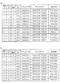
図7、図8を参照して、本実施の形態を適用した場合の各画像形成装置のログデータと統合されたログデータとを説明する。
図7(a)には、第1画像形成装置のログデータの例を示し、図7(b)には、第2画像形成装置のログデータの例を示す。図8には、図7に示す各画像形成装置のログデータを時系列順に並べ替えて統合したログデータの例を示す。
With reference to FIG. 7 and FIG. 8, log data of each image forming apparatus and log data integrated when this embodiment is applied will be described.
FIG. 7A shows an example of log data of the first image forming apparatus, and FIG. 7B shows an example of log data of the second image forming apparatus. FIG. 8 shows an example of log data obtained by rearranging and integrating the log data of each image forming apparatus shown in FIG.
図7(a)に示すように、第1画像形成装置のログデータには、自装置の識別情報を示す装置ID(ここでは「1」)と、ジョブID、ページ番号、ユーザ名、ドキュメント名、タイムスタンプ、動作状態を示すデータが含まれている。
また、図7(b)に示すように、第2画像形成装置のログデータにも、第1画像形成装置のログデータと同様に、自装置の識別情報を示す装置ID(ここでは「2」)と、ジョブID、ページ番号、ユーザ名、ドキュメント名、タイムスタンプ、動作状態を示すデータが含まれている。
As shown in FIG. 7A, the log data of the first image forming apparatus includes a device ID (here, “1”) indicating the identification information of the own device, a job ID, a page number, a user name, and a document name. , Time stamp, and data indicating the operation state are included.
Further, as shown in FIG. 7B, the log data of the second image forming apparatus also includes a device ID (here, “2”) indicating the identification information of the own apparatus, similarly to the log data of the first image forming apparatus. ), Job ID, page number, user name, document name, time stamp, and data indicating the operation state.
図7(a)を参照すると、第1画像形成装置において、ジョブIDが1の7ページ目の動作が一時停止していたことがわかる。しかし、この一時停止した原因が何であるかが第1画像形成装置のログデータ(図7(a))だけでは判断できない。そこで、第2画像形成装置のログデータ(図7(b))を参照すると、ジョブIDが1の6ページ目の動作中にJAMが発生していることがわかる。従って、第1画像形成装置での動作の一時停止が生じた原因は、第2画像形成装置におけるJAMの発生であると把握できる。
このように、各画像形成装置のログデータが個別に表示されると、画像形成装置間での動作の因果関係を掴みづらい。
Referring to FIG. 7A, it can be seen that the operation of the seventh page with the
As described above, when the log data of each image forming apparatus is individually displayed, it is difficult to grasp the causal relationship between the operations of the image forming apparatuses.
一方、図8を参照すると、第1画像形成装置の装置IDを含むログデータ、及び、第2画像形成装置の装置IDを含むログデータを時系列で並べ替えて統合しているため、第2画像形成装置においてJAMが発生したことにより第1画像形成装置での動作が一時停止していたことが一目で把握することができる。 On the other hand, referring to FIG. 8, the log data including the apparatus ID of the first image forming apparatus and the log data including the apparatus ID of the second image forming apparatus are rearranged in time series and integrated. It can be grasped at a glance that the operation of the first image forming apparatus is temporarily stopped due to the occurrence of JAM in the image forming apparatus.
図9、図10を参照して、本実施の形態を適用した場合の各画像形成装置のログデータと統合されたログデータとの他の例を説明する。
図9(a)には、第1画像形成装置のログデータの例を示し、図9(b)には、第2画像形成装置のログデータの例を示す。図10には、図9に示す各画像形成装置のログデータをページ順に並べ替えて統合したログデータの例を示す。
With reference to FIGS. 9 and 10, another example of log data of each image forming apparatus and integrated log data when this embodiment is applied will be described.
FIG. 9A shows an example of log data of the first image forming apparatus, and FIG. 9B shows an example of log data of the second image forming apparatus. FIG. 10 shows an example of log data obtained by rearranging the log data of each image forming apparatus shown in FIG. 9 and integrating them.
図9(a)を参照すると、第1画像形成装置において、ジョブIDが3の1ページ目の動作中にトナー切れが発生しているが、図9(b)を参照すると、第2画像形成装置では、問題なく動作しているように見え、第1画像形成装置でのトナー切れによる影響があったのかを把握することが困難である。
Referring to FIG. 9A, the first image forming apparatus has run out of toner during the operation of the first page with the
一方、図10を参照すると、第1画像形成装置においてジョブIDが3の1ページ目の動作中にトナー切れが発生したことによって、当該トナー切れが解消するまで、第2画像形成装置でのジョブIDが3の2ページ目の動作の開始時刻が遅れていることが一目で把握することができる。
On the other hand, referring to FIG. 10, a job in the second image forming apparatus until the toner out is eliminated by the occurrence of toner out during the operation of the first page of
なお、統合されたログデータを操作表示部22に表示させる際には、装置IDに応じてログデータの表示形態(例えば、背景色、文字の太さや色等)を異ならせて表示させることが好ましい。
When the integrated log data is displayed on the
以上のように、本実施の形態によれば、2台の画像形成装置が直列的に連結されたタンデム構成の画像形成システム1において、統合されて表示されるログデータには、画像形成装置の装置IDが付加されているため、各ログデータがどの画像形成装置のログデータであるかの把握や他の画像形成装置のログデータとの関連性の把握が容易となり、画像形成システム全体のログデータの把握容易性を高めることができ、利便性を向上させることができる。
As described above, according to the present embodiment, in the tandem-type
更に、ログ表示種別選択画面から入力された表示順番の種類に応じて並べ替えて統合されたログデータを表示することができる。そのため、ユーザが希望する表示順番でログデータを並び替えて統合して表示でき、ユーザ自らがログデータを並び替えて統合する手間を省くことができる。 Furthermore, the log data that is rearranged and integrated according to the type of display order input from the log display type selection screen can be displayed. Therefore, the log data can be rearranged and displayed in the display order desired by the user, and the user can save time and effort to rearrange and integrate the log data.
また、複数の画像形成装置のうち少なくともいずれか一つに設けられた操作表示部(本実施の形態では、第1画像形成装置の操作表示部22)に統合されたログデータを表示することができる。
Further, the log data integrated may be displayed on an operation display unit (in this embodiment, the
また、複数の画像形成装置のうち少なくともいずれか一つの画像形成装置とネットワークを介して通信可能に接続された外部装置(本実施の形態では、第1画像形成装置と接続された外部装置2)の表示部に統合されたログデータを表示することができる。
Also, an external device that is communicably connected to at least one of the plurality of image forming apparatuses via a network (in the present embodiment, the
更に、ログ表示形式選択画面から入力された表示形式に応じて、画像形成装置それぞれのログデータを個別に表示させる、又は、統合して表示させることができる。 Furthermore, according to the display format input from the log display format selection screen, the log data of each image forming apparatus can be displayed individually or integratedly displayed.
なお、本実施の形態では、ログデータ表示処理が第1画像形成装置の制御部250により実行される場合について説明したが、これに限らず、第2画像形成装置の制御部450により実行されてもよい。
In this embodiment, the case where the log data display process is executed by the
以上の説明では、本発明に係るプログラムのコンピュータ読み取り可能な媒体として、不揮発メモリ251、451を使用した例を開示したが、この例に限定されない。
その他のコンピュータ読み取り可能な媒体として、フラッシュメモリ等の不揮発性メモリ、CD-ROM等の可搬型記録媒体を適用することが可能である。
また、本発明に係るプログラムのデータを通信回線を介して提供する媒体として、キャリアウエーブ(搬送波)も本発明に適用される。
In the above description, the example in which the
As other computer-readable media, a non-volatile memory such as a flash memory and a portable recording medium such as a CD-ROM can be applied.
A carrier wave is also applied to the present invention as a medium for providing program data according to the present invention via a communication line.
また、本発明は、上記実施の形態の内容に限定されるものではなく、本発明の主旨を逸脱しない範囲で適宜変更可能である。 Further, the present invention is not limited to the contents of the above embodiment, and can be appropriately changed without departing from the gist of the present invention.
1 画像形成システム
2 外部装置
3 ネットワーク
10 給紙装置
20 第1画像形成装置
21 画像読取部
22 操作表示部
23 プリント部
24 コントローラ
25 画像制御基板
26 HDD
27 通信部
30 反転装置
40 第2画像形成装置
42 操作表示部
43 プリント部
44 コントローラ
45 画像制御基板
46 HDD
47 通信部
50 後処理装置
210 画像読取制御部
211 CCD
220 操作表示制御部
221 LCD
230 プリント制御部
231 給紙部
232 用紙搬送部
232a 反転搬送部
233 画像形成部
233a 中間転写ベルト
234 定着部
241 コントローラ制御部
242 DRAM制御IC
243 画像メモリ
244 LANIF
250 制御部
251 不揮発メモリ
252 RAM
253 読取処理部
254 圧縮IC
255 DRAM制御IC
256 画像メモリ
256a 圧縮メモリ
256b ページメモリ
257 伸長IC
258 書込処理部
450 制御部
451 不揮発メモリ
452 RAM
454 圧縮IC
455 DRAM制御IC
456 画像メモリ
456a 圧縮メモリ
456b ページメモリ
457 伸長IC
458 書込処理部
B11 個別表示ボタン
B12 マージ表示ボタン
B21 時系列順ボタン
B22 ページ順ボタン
B23 ジョブ順ボタン
G1 ログ表示形式選択画面
G2 ログ表示種別選択画面
M1 メッセージ領域
M2 メッセージ領域
DESCRIPTION OF
27
47
220
230
243
250
253
255 DRAM control IC
256
258
454 compression IC
455 DRAM control IC
456
458 Write processing unit B11 Individual display button B12 Merge display button B21 Time series order button B22 Page order button B23 Job order button G1 Log display format selection screen G2 Log display type selection screen M1 Message area M2 Message area
Claims (6)
前記画像形成装置それぞれは、
自装置の識別情報が付加され、1ページの画像形成処理の開始や終了を含む動作履歴情報を蓄積する記憶部を有し、
前記複数の画像形成装置のうち少なくとも一つの画像形成装置は、
前記複数の画像形成装置それぞれの前記記憶部から前記動作履歴情報を取得し、当該取得した前記動作履歴情報をあわせて表示対象として、表示順番を連携動作の履歴が把握可能なように、時系列あるいはページ順に並び替えて一枚の用紙に対応する複数の画像形成装置の動作履歴として統合し、前記統合された動作履歴情報を、当該動作履歴情報毎に付加された前記識別情報と共に表示するための表示信号を出力する制御部を備えること、
を特徴とする画像形成システム。 A series tandem configuration in which a plurality of image forming apparatuses are connected in series forms an image on one side of the sheet with the upstream side image forming apparatus in the sheet conveyance path, and the other side of the sheet with the downstream side image forming apparatus. In an image forming system that forms an image on a surface and forms an image on a sheet of paper,
Each of the image forming apparatuses
A storage unit for accumulating operation history information including the start and end of image formation processing for one page, to which identification information of the own device is added;
At least one image forming apparatus among the plurality of image forming apparatuses is:
The operation history information is acquired from the storage unit of each of the plurality of image forming apparatuses, and the acquired operation history information is combined as a display target so that the history of the cooperative operation can be grasped in order of display order. Alternatively, in order to arrange the operation history of a plurality of image forming apparatuses corresponding to one sheet by rearranging the pages, and to display the integrated operation history information together with the identification information added for each operation history information. A control unit for outputting the display signal of
An image forming system.
を特徴とする請求項1に記載の画像形成システム。 A display unit for displaying the integrated operation history information together with the identification information added for each operation history information based on the display signal;
The image forming system according to claim 1.
前記制御部は、
前記表示順番入力部から入力された前記表示順番の種類に応じて前記動作履歴情報を並べ替えて統合すること、
を特徴とする請求項2に記載の画像形成システム。 When displaying the integrated operation history information on the display unit includes a display order input portion to which the type of the display order of the instruction of the operation history information is inputted,
The controller is
Rearranging and integrating the operation history information according to the type of the display order input from the display order input unit;
The image forming system according to claim 2.
前記複数の画像形成装置のうち少なくともいずれか一つに設けられていること、
を特徴とする請求項2又は3に記載の画像形成システム。 The display unit
Provided in at least one of the plurality of image forming apparatuses;
The image forming system according to claim 2, wherein:
前記複数の画像形成装置のうち少なくともいずれか一つの画像形成装置とネットワークを介して通信可能に接続されていること、
を特徴とする請求項2から4のいずれか一項に記載の画像形成システム。 The display unit
Being communicably connected to at least one of the plurality of image forming apparatuses via a network;
The image forming system according to claim 2, wherein:
前記制御部は、
前記表示選択入力部に入力された選択指示に応じて、前記画像形成装置それぞれの動作履歴情報を個別に前記表示部に表示させる、又は、統合して前記表示部に表示させること、
を特徴とする請求項2から5のいずれか一項に記載の画像形成システム。 A display selection input unit for inputting a selection instruction as to whether or not to display the operation history information of each of the image forming apparatuses individually or to display them in an integrated manner,
The controller is
In response to a selection instruction input to the display selection input unit, the operation history information of each of the image forming apparatuses is individually displayed on the display unit, or integrated and displayed on the display unit.
The image forming system according to any one of claims 2 to 5, wherein:
Priority Applications (1)
| Application Number | Priority Date | Filing Date | Title |
|---|---|---|---|
| JP2010259642A JP5786314B2 (en) | 2010-11-22 | 2010-11-22 | Image forming system |
Applications Claiming Priority (1)
| Application Number | Priority Date | Filing Date | Title |
|---|---|---|---|
| JP2010259642A JP5786314B2 (en) | 2010-11-22 | 2010-11-22 | Image forming system |
Publications (3)
| Publication Number | Publication Date |
|---|---|
| JP2012111058A JP2012111058A (en) | 2012-06-14 |
| JP2012111058A5 JP2012111058A5 (en) | 2013-08-15 |
| JP5786314B2 true JP5786314B2 (en) | 2015-09-30 |
Family
ID=46495806
Family Applications (1)
| Application Number | Title | Priority Date | Filing Date |
|---|---|---|---|
| JP2010259642A Active JP5786314B2 (en) | 2010-11-22 | 2010-11-22 | Image forming system |
Country Status (1)
| Country | Link |
|---|---|
| JP (1) | JP5786314B2 (en) |
Families Citing this family (2)
| Publication number | Priority date | Publication date | Assignee | Title |
|---|---|---|---|---|
| JP2016095428A (en) * | 2014-11-14 | 2016-05-26 | 京セラドキュメントソリューションズ株式会社 | Method of acquiring setting values for inspection of image forming apparatus, and image forming apparatus |
| JP6497254B2 (en) * | 2015-07-27 | 2019-04-10 | コニカミノルタ株式会社 | Image forming system |
Family Cites Families (4)
| Publication number | Priority date | Publication date | Assignee | Title |
|---|---|---|---|---|
| JP2004295305A (en) * | 2003-03-26 | 2004-10-21 | Dainippon Printing Co Ltd | Off-line printer monitoring device |
| JP2009104582A (en) * | 2007-10-03 | 2009-05-14 | Ricoh Co Ltd | Printing system and print control method |
| JP2009193302A (en) * | 2008-02-14 | 2009-08-27 | Seiko Epson Corp | Printing system, management server, registered user terminal, print management program, automatic printing program, and automatic printing method |
| JP2010012705A (en) * | 2008-07-04 | 2010-01-21 | Ricoh Co Ltd | Printer system |
-
2010
- 2010-11-22 JP JP2010259642A patent/JP5786314B2/en active Active
Also Published As
| Publication number | Publication date |
|---|---|
| JP2012111058A (en) | 2012-06-14 |
Similar Documents
| Publication | Publication Date | Title |
|---|---|---|
| US20120200886A1 (en) | Image forming system | |
| US8705098B2 (en) | Preventing print delay due to transfer of data regarding image forming and to enhance productivity in an image forming system with a tandem configuration including a plurality of image forming apparatuses | |
| JP2012206461A (en) | Control apparatus, setting method of inspection processing, and program | |
| JP2013129155A (en) | Image forming system and program | |
| JP5208283B2 (en) | Printing apparatus, printing apparatus control method, and program | |
| JP2012143964A (en) | Image forming system | |
| JP5919875B2 (en) | Printing system and image inspection apparatus | |
| JP2011059344A (en) | Image forming apparatus, method of controlling image forming apparatus, and program | |
| JP6435951B2 (en) | Image generation apparatus, control program for image generation apparatus, and control method for image generation apparatus. | |
| JP5640643B2 (en) | Image forming system | |
| JP5786314B2 (en) | Image forming system | |
| JP5370550B2 (en) | Image forming apparatus, program, and method executed in image forming apparatus | |
| JP7451224B2 (en) | Image forming device | |
| JP2008068471A (en) | Image forming system and method for controlling the same | |
| JP2010151883A (en) | Image forming apparatus and image forming method | |
| JP2016126071A (en) | Image formation device, image formation system, and image formation control method | |
| JP2009063818A (en) | Image forming apparatus | |
| US20120093536A1 (en) | Image forming system | |
| JP2008063077A (en) | Image forming system | |
| JP2007045093A (en) | Image forming device, image forming system, program and post-processing control method | |
| US11656811B2 (en) | Print system, information processing apparatus, printing apparatus, method of controlling the same, and storage medium | |
| JP2012141472A (en) | Image formation system | |
| JP5707900B2 (en) | Image forming system and accounting method for image forming system | |
| JP7146463B2 (en) | IMAGE FORMING APPARATUS, AND IMAGE FORMING APPARATUS CONTROL METHOD AND PROGRAM | |
| JP2013000905A (en) | Image forming system |
Legal Events
| Date | Code | Title | Description |
|---|---|---|---|
| A711 | Notification of change in applicant |
Free format text: JAPANESE INTERMEDIATE CODE: A712 Effective date: 20130416 |
|
| A621 | Written request for application examination |
Free format text: JAPANESE INTERMEDIATE CODE: A621 Effective date: 20130618 |
|
| A521 | Written amendment |
Free format text: JAPANESE INTERMEDIATE CODE: A523 Effective date: 20130702 |
|
| A977 | Report on retrieval |
Free format text: JAPANESE INTERMEDIATE CODE: A971007 Effective date: 20140207 |
|
| A131 | Notification of reasons for refusal |
Free format text: JAPANESE INTERMEDIATE CODE: A131 Effective date: 20140218 |
|
| A521 | Written amendment |
Free format text: JAPANESE INTERMEDIATE CODE: A523 Effective date: 20140417 |
|
| A131 | Notification of reasons for refusal |
Free format text: JAPANESE INTERMEDIATE CODE: A131 Effective date: 20141202 |
|
| A521 | Written amendment |
Free format text: JAPANESE INTERMEDIATE CODE: A523 Effective date: 20150202 |
|
| TRDD | Decision of grant or rejection written | ||
| A01 | Written decision to grant a patent or to grant a registration (utility model) |
Free format text: JAPANESE INTERMEDIATE CODE: A01 Effective date: 20150630 |
|
| A61 | First payment of annual fees (during grant procedure) |
Free format text: JAPANESE INTERMEDIATE CODE: A61 Effective date: 20150713 |
|
| R150 | Certificate of patent (=grant) or registration of utility model |
Ref document number: 5786314 Country of ref document: JP Free format text: JAPANESE INTERMEDIATE CODE: R150 |