JP5772911B2 - Fault tolerant system - Google Patents
Fault tolerant system Download PDFInfo
- Publication number
- JP5772911B2 JP5772911B2 JP2013200874A JP2013200874A JP5772911B2 JP 5772911 B2 JP5772911 B2 JP 5772911B2 JP 2013200874 A JP2013200874 A JP 2013200874A JP 2013200874 A JP2013200874 A JP 2013200874A JP 5772911 B2 JP5772911 B2 JP 5772911B2
- Authority
- JP
- Japan
- Prior art keywords
- subsystem
- unit
- processor unit
- input
- data
- Prior art date
- Legal status (The legal status is an assumption and is not a legal conclusion. Google has not performed a legal analysis and makes no representation as to the accuracy of the status listed.)
- Expired - Fee Related
Links
Images


Classifications
-
- G—PHYSICS
- G06—COMPUTING; CALCULATING OR COUNTING
- G06F—ELECTRIC DIGITAL DATA PROCESSING
- G06F11/00—Error detection; Error correction; Monitoring
- G06F11/07—Responding to the occurrence of a fault, e.g. fault tolerance
- G06F11/16—Error detection or correction of the data by redundancy in hardware
- G06F11/1629—Error detection by comparing the output of redundant processing systems
- G06F11/1641—Error detection by comparing the output of redundant processing systems where the comparison is not performed by the redundant processing components
-
- G—PHYSICS
- G06—COMPUTING; CALCULATING OR COUNTING
- G06F—ELECTRIC DIGITAL DATA PROCESSING
- G06F11/00—Error detection; Error correction; Monitoring
- G06F11/07—Responding to the occurrence of a fault, e.g. fault tolerance
- G06F11/16—Error detection or correction of the data by redundancy in hardware
- G06F11/1629—Error detection by comparing the output of redundant processing systems
- G06F11/165—Error detection by comparing the output of redundant processing systems with continued operation after detection of the error
-
- G—PHYSICS
- G06—COMPUTING; CALCULATING OR COUNTING
- G06F—ELECTRIC DIGITAL DATA PROCESSING
- G06F11/00—Error detection; Error correction; Monitoring
- G06F11/07—Responding to the occurrence of a fault, e.g. fault tolerance
- G06F11/16—Error detection or correction of the data by redundancy in hardware
- G06F11/1629—Error detection by comparing the output of redundant processing systems
- G06F11/1654—Error detection by comparing the output of redundant processing systems where the output of only one of the redundant processing components can drive the attached hardware, e.g. memory or I/O
-
- G—PHYSICS
- G06—COMPUTING; CALCULATING OR COUNTING
- G06F—ELECTRIC DIGITAL DATA PROCESSING
- G06F2201/00—Indexing scheme relating to error detection, to error correction, and to monitoring
- G06F2201/83—Indexing scheme relating to error detection, to error correction, and to monitoring the solution involving signatures
Description
本発明は、フォールトトレラントシステム、それに用いる制御装置、それらの動作方法、およびプログラムに関する。 The present invention relates to a fault tolerant system, a control device used therefor, an operation method thereof, and a program.
可用性を高めた計算機システムとして、フォールトトレラントシステムが知られている。フォールトトレラントシステムでは、アプリケーションやOSが特別な処理を必要としないで、透過的にサービスを継続することができる。フォールトトレラントシステムを実現する方式は、ハードウェア方式とソフトウェア方式とに大別される。本発明は、ハードウェア方式のフォールトトレラントシステムの改良に関する。 A fault tolerant system is known as a computer system with high availability. In the fault tolerant system, the application and OS do not require special processing, and the service can be continued transparently. Methods for realizing a fault tolerant system are roughly classified into hardware methods and software methods. The present invention relates to an improvement in a hardware type fault tolerant system.
ハードウェア方式のフォールトトレラントシステムは、CPU、メモリ、ストレージなどの主要なハードウェアコンポーネントを冗長化し、あるコンポーネントに障害が発生した場合は、そのコンポーネントを切り離して動作を継続する。CPUやメモリを含むモジュールをCPUサブシステム、各種IOデバイスを含むモジュールをIOサブシステムと呼ぶ。コンポーネントを二重化する一般的なフォールトトレラントシステムでは、CPUサブシステムとIOサブシステムとで二重化の方式が異なる。CPUサブシステムは、クロック単位でハードウェアの動作を完全に一致させる。これをロックステップ同期と呼ぶ。二重化されたCPUサブシステムは、両方とも完全に同じ動作をしているので、障害発生時はその障害が発生したCPUサブシステムを論理的に切り離し、正常なCPUサブシステムに瞬時に処理を切り換えて動作を継続させる。一方、IOサブシステムは、ロックステップ同期こそしていないが、障害が発生した場合、直ちに他方のIOサブシステムに切り換える。 The hardware-type fault tolerant system makes main hardware components such as CPU, memory, storage, etc. redundant, and when a failure occurs in a certain component, the operation is performed by separating the component. A module including a CPU and a memory is referred to as a CPU subsystem, and a module including various IO devices is referred to as an IO subsystem. In a general fault-tolerant system in which components are duplicated, the duplication scheme is different between the CPU subsystem and the IO subsystem. The CPU subsystem perfectly matches hardware operations in units of clocks. This is called lockstep synchronization. Since both of the duplicated CPU subsystems are operating in exactly the same manner, when a failure occurs, the CPU subsystem in which the failure has occurred is logically disconnected, and processing is instantaneously switched to a normal CPU subsystem. Continue operation. On the other hand, the IO subsystem does not perform lockstep synchronization, but immediately switches to the other IO subsystem when a failure occurs.
ロックステップ同期の状態において、CPUサブシステムの不正な動作を検出する方法として、各CPUサブシステムからIOサブシステムへアクセスするデータを比較する方法がある。その際、各サブシステムが、自サブシステムのCPUで生成したアクセスデータからチェックサムを生成してクロスリンクを介して他サブシステムへ送信する一方、上記生成したチェックサムとクロスリンクを介して他サブシステムから受信したチェックサムとを比較してサブシステム間の処理の不一致を検知することが、本発明に関連する第1の関連技術として提案されている(例えば特許文献1参照)。 As a method of detecting an illegal operation of the CPU subsystem in the lock step synchronization state, there is a method of comparing data accessed from each CPU subsystem to the IO subsystem. At that time, each subsystem generates a checksum from the access data generated by the CPU of its own subsystem and transmits it to the other subsystem via the cross link. It has been proposed as a first related technique related to the present invention to detect a processing mismatch between subsystems by comparing the checksum received from the subsystem (see, for example, Patent Document 1).
その他、フォールトトレラントシステムに関して、以下のような先行技術がある。 In addition, there are the following prior arts regarding the fault-tolerant system.
まず、自他システム間でクロックステップ同期により同じタイミングで動作するCPUサブシステムと、これに接続されるIOサブシステムと、両者間に接続されるFTコントローラとを有する2つのシステムをクロスリンクによって互いに接続したフォールトトレラントシステムにおいて、FTコントローラが、両システムによるフォールトトレラント用のエラー処理、二重化処理、および再同期化処理を行うための複数のシステム動作をこれに対応する複数ステートとして所定のイベント信号に関連付けて管理し、イベント信号に応じて、システム毎にステートを遷移させながら複数のシステム動作を選択してCPUサブシステムに実行させることが、本発明に関連する第2の関連技術として提案されている(例えば特許文献2参照)。 First, two systems having a CPU subsystem operating at the same timing by clock step synchronization between the own system and another system, an IO subsystem connected thereto, and an FT controller connected between the two systems are cross-linked to each other. In a connected fault-tolerant system, the FT controller converts multiple system operations for performing fault-tolerant error processing, duplex processing, and resynchronization processing by both systems into a predetermined event signal as a corresponding multiple state. It is proposed as a second related technique related to the present invention that a plurality of system operations are selected and executed by the CPU subsystem while transitioning states for each system according to event signals in association with each other. (For example, refer to Patent Document 2).
また、上記フォールトトレラントシステムにおいて、CPUサブシステムからIOサブシステムへのアクセスパケットに、アクセス元およびアクセス先のIDコードと、同期アクセスか否かの同期情報とを含むタグ情報を付与し、各々のシステムのアクセス比較部が、アクセスパケットに付与されたタグ情報に基づいて、複数のCPUサブシステムがロックステップ同期状態にある場合のアクセス処理を行うか、非同期状態に応じたアクセス処理を行うかを決定することが、本発明に関連する第3の関連技術として提案されている(例えば特許文献3参照)。 Further, in the fault tolerant system, tag information including an access source and an access destination ID code and synchronous information indicating whether or not synchronous access is given to an access packet from the CPU subsystem to the IO subsystem, Whether the access comparison unit of the system performs access processing when a plurality of CPU subsystems are in the lockstep synchronous state or performs access processing according to the asynchronous state based on the tag information given to the access packet The determination is proposed as a third related technique related to the present invention (see, for example, Patent Document 3).
本発明に関連する第1の関連技術では、パケットそのものでなくパケットから生成したチェックサムをクロスリンクを介して他サブシステムへ送信する一方、上記生成したチェックサムとクロスリンクを介して他サブシステムから受信したチェックサムとを比較してサブシステム間の処理の不一致を検知している。これにより、パケットそのものをクロスリンクを介して他サブシステムへ送信する場合に比べて、クロスリンクを流れるデータ量を低減することができる。しかしながら、パケットそのものでなくパケットから生成したチェックサムをクロスリンクを介して他サブシステムへ送信する上記第1の関連技術では、フォールトトレラントシステムをロックステップ非同期の状態で動作させるのは困難である。その理由は、パケットから生成したチェックサムをクロスリンクを介して他サブシステムへ送信しても、他サブシステム側にその元となるパケットと同じパケットが存在しないロックステップ非同期の状態では他サブシステムの入出力部をアクセスできないためである。他方、本発明に関連する第3の関連技術では、フォールトトレラントシステムをロックステップ同期の状態およびロックステップ非同期の状態の双方の状態で動作させることが可能であるが、パケットそのものをクロスリンクを介して送信するため、クロスリンクを流れるデータ量を低減することは困難である。 In the first related technology related to the present invention, the checksum generated from the packet, not the packet itself, is transmitted to the other subsystem via the crosslink, while the other subsystem is transmitted via the crosslink to the generated checksum. Compared with the checksum received from the server, the processing mismatch between the subsystems is detected. Thereby, the amount of data flowing through the cross link can be reduced as compared with the case where the packet itself is transmitted to the other subsystem via the cross link. However, it is difficult to operate the fault tolerant system in an asynchronous state of the lock step in the first related technique in which the checksum generated from the packet instead of the packet itself is transmitted to the other subsystems via the cross link. The reason is that even if a checksum generated from a packet is transmitted to another subsystem via a cross link, the same packet as the original packet does not exist on the other subsystem side. This is because the input / output part of the system cannot be accessed. On the other hand, in the third related technique related to the present invention, it is possible to operate the fault tolerant system in both the lock step synchronous state and the lock step asynchronous state, but the packet itself is transmitted via the cross link. Therefore, it is difficult to reduce the amount of data flowing through the cross link.
本発明の目的は、上述した課題、すなわち、サブシステム間を接続する信号伝送路を流れるデータ量を低減しつつ、フォールトトレラントシステムをロックステップ同期の状態およびロックステップ非同期の状態の双方の状態で動作させるのは困難である、という課題を解決するフォールトトレラントシステムを提供することにある。 The object of the present invention is to reduce the amount of data flowing through the signal transmission path connecting the subsystems, while maintaining the fault tolerant system in both the lock step synchronous state and the lock step asynchronous state. The object is to provide a fault tolerant system that solves the problem of being difficult to operate.
本発明の第1の観点に係るフォールトトレラントシステムは、
互いに同一のハードウェアで構成された複数のサブシステムを備えたフォールトトレラントシステムであって、
上記複数のサブシステムは、
上記複数のサブシステム間においてロックステップ同期の状態および非同期の状態で動作可能なプロセッサ部と、
上記プロセッサ部に接続される入出力部と、
上記プロセッサ部および上記入出力部間に接続される制御部と、
上記制御部を介して上記複数のサブシステム間を互いに接続する信号伝送路とを有し、
上記制御部は、上記プロセッサ部がロックステップ同期の状態にあるときは、自サブシステムの上記プロセッサ部から上記入出力部へアクセスされるデータから生成した誤り検出用データの他サブシステムへの送信を行い、ロックステップ非同期の状態にあるときは、自サブシステムの上記プロセッサ部から上記入出力部へアクセスされるデータの他サブシステムへの送信を行う。
The fault tolerant system according to the first aspect of the present invention is:
A fault tolerant system comprising a plurality of subsystems composed of the same hardware,
The multiple subsystems are:
A processor unit operable between a lock step synchronization state and an asynchronous state between the plurality of subsystems;
An input / output unit connected to the processor unit;
A control unit connected between the processor unit and the input / output unit;
A signal transmission path for connecting the plurality of subsystems to each other via the control unit;
When the processor unit is in lock step synchronization, the control unit transmits error detection data generated from data accessed from the processor unit of the subsystem to the input / output unit to the other subsystem. When the lock step is asynchronous, the data accessed from the processor unit of the own subsystem to the input / output unit is transmitted to the other subsystem.
本発明の第2の観点に係るフォールトトレラントシステムで用いる制御装置は、
同一のハードウェアで構成された複数のサブシステムで構成されるフォールトトレラントシステムの各サブシステムで用いる制御装置であって、
自他サブシステム間においてロックステップ同期の状態および非同期の状態で動作可能なプロセッサ部と上記プロセッサ部に接続される入出力部との間に接続され、また、自他サブシステム間を互いに接続する信号伝送路に接続され、
上記プロセッサ部がロックステップ同期の状態にあるときは、自サブシステムの上記プロセッサ部から上記入出力部へアクセスされるデータから生成した誤り検出用データの他サブシステムへの送信を行い、ロックステップ非同期の状態にあるときは、自サブシステムの上記プロセッサ部から上記入出力部へアクセスされるデータの他サブシステムへの送信を行う。
The control device used in the fault tolerant system according to the second aspect of the present invention is:
A control device used in each subsystem of a fault tolerant system composed of a plurality of subsystems composed of the same hardware,
Connected between the processor unit operable in the lockstep synchronous state and the asynchronous state between the own and other subsystems and the input / output unit connected to the processor unit, and also connected between the own and other subsystems. Connected to the signal transmission path,
When the processor unit is in the lock step synchronization state, the error detection data generated from the data accessed from the processor unit of the own subsystem to the input / output unit is transmitted to the other subsystem, and the lock step is performed. When in an asynchronous state, data accessed from the processor unit of the sub-system to the input / output unit is transmitted to another sub-system.
本発明の第3の観点に係るフォールトトレラントシステムの動作方法は、
互いに同一のハードウェアで構成された複数のサブシステムを備え、上記複数のサブシステムは、上記複数のサブシステム間においてロックステップ同期の状態および非同期の状態で動作可能なプロセッサ部と、上記プロセッサ部に接続される入出力部と、上記プロセッサ部および上記入出力部間に接続される制御部と、上記制御部を介して上記複数のサブシステム間を互いに接続する信号伝送路とを有するフォールトトレラントシステムの動作方法であって、
上記制御部が、
上記プロセッサ部がロックステップ同期の状態にあるときは、自サブシステムの上記プロセッサ部から上記入出力部へアクセスされるデータから生成した誤り検出用データの他サブシステムへの送信を行い、ロックステップ非同期の状態にあるときは、自サブシステムの上記プロセッサ部から上記入出力部へアクセスされるデータの他サブシステムへの送信を行う。
The operation method of the fault tolerant system according to the third aspect of the present invention is:
A plurality of subsystems configured by the same hardware as each other, wherein the plurality of subsystems are capable of operating in a lockstep synchronization state and an asynchronous state between the plurality of subsystems, and the processor unit A fault tolerant comprising: an input / output unit connected to the control unit; a control unit connected between the processor unit and the input / output unit; and a signal transmission path for connecting the plurality of subsystems to each other via the control unit A system operation method,
The control unit is
When the processor unit is in the lock step synchronization state, the error detection data generated from the data accessed from the processor unit of the own subsystem to the input / output unit is transmitted to the other subsystem, and the lock step is performed. When in an asynchronous state, data accessed from the processor unit of the sub-system to the input / output unit is transmitted to another sub-system.
本発明の第4の観点に係るフォールトトレラントシステムで用いる制御装置の動作方法は、
同一のハードウェアで構成された複数のサブシステムで構成されるフォールトトレラントシステムの各サブシステムで用いられ、自他サブシステム間においてロックステップ同期の状態および非同期の状態で動作可能なプロセッサ部と上記プロセッサ部に接続される入出力部との間に接続され、また、自他サブシステム間を互いに接続する信号伝送路に接続される制御装置の動作方法であって、
上記制御装置が、上記プロセッサ部がロックステップ同期の状態にあるときは、自サブシステムの上記プロセッサ部から上記入出力部へアクセスされるデータから生成した誤り検出用データの他サブシステムへの送信を行い、ロックステップ非同期の状態にあるときは、自サブシステムの上記プロセッサ部から上記入出力部へアクセスされるデータの他サブシステムへの送信を行う。
The operation method of the control device used in the fault tolerant system according to the fourth aspect of the present invention is:
A processor unit that is used in each subsystem of a fault tolerant system composed of a plurality of subsystems composed of the same hardware, and that can operate between its own and other subsystems in a lockstep synchronous state and an asynchronous state; and An operation method of a control device connected between an input / output unit connected to a processor unit and connected to a signal transmission path connecting the own and other subsystems to each other,
When the processor unit is in the lockstep synchronization state, the control device transmits error detection data generated from data accessed from the processor unit of the own subsystem to the input / output unit to another subsystem. When the lock step is asynchronous, the data accessed from the processor unit of the own subsystem to the input / output unit is transmitted to the other subsystem.
本発明の第4の観点に係るプログラムは、
同一のハードウェアで構成された複数のサブシステムで構成されるフォールトトレラントシステムの各サブシステムで用いられ、自他サブシステム間においてロックステップ同期の状態および非同期の状態で動作可能なプロセッサ部と上記プロセッサ部に接続される入出力部との間に接続され、また、自他サブシステム間を互いに接続する信号伝送路に接続された制御装置を構成するコンピュータに、
上記プロセッサ部がロックステップ同期の状態にあるときは、自サブシステムの上記プロセッサ部から上記入出力部へアクセスされるデータから生成した誤り検出用データの他サブシステムへの送信を行わせ、
ロックステップ非同期の状態にあるときは、自サブシステムの上記プロセッサ部から上記入出力部へアクセスされるデータの他サブシステムへの送信を行わせる。
The program according to the fourth aspect of the present invention is:
A processor unit that is used in each subsystem of a fault tolerant system composed of a plurality of subsystems composed of the same hardware, and that can operate between its own and other subsystems in a lockstep synchronous state and an asynchronous state; and The computer constituting the control device connected between the input / output unit connected to the processor unit and connected to the signal transmission path connecting the other subsystems to each other,
When the processor unit is in a lockstep synchronization state, the error detection data generated from the data accessed from the processor unit of the own subsystem to the input / output unit is transmitted to the other subsystem,
When the lock step is asynchronous, the data accessed from the processor unit of the sub-system to the input / output unit is transmitted to the other sub-system.
本発明は上述した構成を有するため、サブシステム間を接続する信号伝送路を流れるデータ量を低減しつつ、フォールトトレラントシステムをロックステップ同期の状態およびロックステップ非同期の状態の双方の状態で動作させることができる。 Since the present invention has the above-described configuration, the fault tolerant system is operated in both the lock step synchronous state and the lock step asynchronous state while reducing the amount of data flowing through the signal transmission path connecting the subsystems. be able to.
次に本発明の実施の形態について図面を参照して詳細に説明する。 Next, embodiments of the present invention will be described in detail with reference to the drawings.
[第1の実施形態]
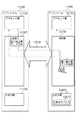
図1を参照すると、本発明の第1の実施形態にかかるフォールトトレラントシステム10000は、互いに同一のハードウェアで構成された2つのサブシステム11000、12000を備えている。
[First Embodiment]
Referring to FIG. 1, a fault-tolerant system 10000 according to the first embodiment of the present invention includes two
サブシステム11000は、プロセッサ部11100、このプロセッサ部11100に接続される入出力部11200、および、プロセッサ部11100と入出力部11200間に接続される制御部11300を有する。また、サブシステム12000は、プロセッサ部12100、このプロセッサ部12100に接続される入出力部12200、および、プロセッサ部12100と入出力部12200間に接続される制御部12300を有する。さらに、制御部11300、12300を介してサブシステム11000とサブシステム12000間を互いに接続する信号伝送路13000が設けられている。
The
プロセッサ部11100とプロセッサ部12100は、サブシステム11000とサブシステム12000とがロックステップ動作している状態(ロックステップ同期の状態)で動作可能であると共に、サブシステム11000とサブシステム12000とがロックステップ動作していない状態(ロックステップ非同期の状態)で動作可能である。
The
制御部11300、12300は、以下のような機能を有する。
The
まず、制御部11300、12300は、プロセッサ部11100、12100がロックステップ同期の状態にあるときは、自サブシステムのプロセッサ部から入出力部へアクセスされるデータから生成した誤り検出用データの他サブシステムへの送信を行う。ここで、誤り検出用データの種類およびその生成方法は、任意である。例えば、プロセッサ部から入出力部へアクセスされるデータが本来のデータ以外にCRC(Cyclic Redundancy Code)を有する場合、このCRCを上記誤り検出用データとして使用して良い。また、プロセッサ部から入出力部へアクセスされるデータに基づいてチェックサムを算出し、この算出したチェックサムを上記誤り検出用データとして使用して良い。
First, when the
他方、プロセッサ部11100、12100がロックステップ非同期の状態にあるときは、制御部11300、12300は、自サブシステムのプロセッサ部から入出力部へアクセスされるデータの他サブシステムへの送信を行う。すなわち、プロセッサ部11100、12100がロックステップ非同期の状態にあるときは、主として、何れか一方のプロセッサ部が停止している。仮にプロセッサ部12100が停止しているとすると、入出力部11200、12200へのアクセスはプロセッサ部11100が担うことになる。このため、制御部11300は、プロセッサ部11100から入出力部12200へアクセスされるデータそのものの他サブシステムへの送信を行う。
On the other hand, when the
次に本実施形態に係るフォールトトレラントシステム10000の動作を説明する。 Next, the operation of the fault tolerant system 10000 according to this embodiment will be described.
まず、プロセッサ部11100、12100がロックステップ同期の状態にあるときの動作を説明する。
First, the operation when the
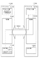
図2は、プロセッサ部11100とプロセッサ部12100とが入出力部11200内の入出力デバイス11210をアクセスするデータを生成したときと、入出力デバイス11210がそのアクセスデータに対する応答データを生成したときのデータの流れを示している。ロックステップ同期の状態にあるので、制御部11300は、入出力部11200内の入出力デバイス11210宛のデータをプロセッサ部11100から受信すると、そのデータから誤り検出用データを作成し、元のデータと上記作成した誤り検出用データとを制御部11300内部のバッファに蓄積して一時的に保存する。他方、制御部12300は、入出力デバイス11210宛のデータをプロセッサ部12100から受信すると、そのデータから誤り検出用データを作成し、信号伝送路13000を介して制御部11300へ送信する。制御部11300は、バッファに蓄積されている誤り検出用データと信号伝送路13000を介して制御部12300から受信した誤り検出用データとを比較する。そして、双方の誤り検出用データが一致した場合に限り、バッファに保持している入出力デバイス11210宛のデータを入出力部11200の入出力デバイス11210へ送信する。これにより、双方の誤り検出用データが一致しないような不正な状況の下で入出力デバイス11210がアクセスされる事態が回避される。
FIG. 2 shows data when the
入出力デバイス11210は、上記データを受信し、上記データに応じた処理を行い、その処理結果を応答データとして生成し、制御部11300へ送信する。ロックステップ同期の状態にあるので、制御部11300は、入出力デバイス11210からのデータを受信すると、プロセッサ部11100へ転送すると共に、信号伝送路13000を介して制御部12300へ転送する。制御部12300は、この転送されてきたデータをプロセッサ部12100へさらに転送する。
The input /
このように、プロセッサ部11100、12100がロックステップ同期の状態にある場合、プロセッサ部12100から入出力デバイス11210宛のデータは信号伝送路13000に送信されず、そのデータから生成された誤り検出用データが信号伝送路13000に送信される。その結果、信号伝送路13000上のデータ量を削減することができる。
As described above, when the
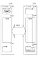
図3は、プロセッサ部11100とプロセッサ部12100とが入出力部12200内の入出力デバイス12210をアクセスするデータを生成したときと、入出力デバイス12210がそのアクセスデータに対する応答データを生成したときのデータの流れを示している。ロックステップ同期の状態にあるので、制御部12300は、入出力部12200内の入出力デバイス12210宛のデータをプロセッサ部12100から受信すると、そのデータから誤り検出用データを作成し、元のデータと上記作成した誤り検出用データとを制御部12300内部のバッファに蓄積して一時的に保存する。他方、制御部11300は、入出力デバイス12210宛のデータをプロセッサ部11100から受信すると、そのデータから誤り検出用データを作成し、信号伝送路13000を介して制御部12300へ送信する。制御部12300は、バッファに蓄積されている誤り検出用データと信号伝送路13000を介して制御部11300から受信した誤り検出用データとを比較する。そして、双方の誤り検出用データが一致した場合に限り、バッファに保持している入出力デバイス12210宛のデータを入出力部12200の入出力デバイス12210へ送信する。これにより、双方の誤り検出用データが一致しないような不正な状況の下で入出力デバイス12210がアクセスされる事態が回避される。
FIG. 3 shows data when the
入出力デバイス12210は、上記データを受信し、上記データに応じた処理を行い、その処理結果を応答データとして生成し、制御部12300へ送信する。ロックステップ同期の状態にあるので、制御部12300は、入出力デバイス12210からのデータを受信すると、プロセッサ部12300へ転送すると共に、信号伝送路13000を介して制御部11300へ転送する。制御部11300は、この転送されてきたデータをプロセッサ部11100へさらに転送する。
The input /
このように、プロセッサ部11100、12100がロックステップ同期の状態にある場合、プロセッサ部11100から入出力デバイス12210宛のデータは信号伝送路13000に送信されず、そのデータから生成された誤り検出用データが信号伝送路13000に送信される。その結果、信号伝送路13000上のデータ量を削減することができる。
As described above, when the
次に、プロセッサ部11100、12100がロックステップ非同期の状態にあるときの動作を説明する。例として、プロセッサ部11100が障害など何らかの理由で稼働を停止し、プロセッサ部12100が稼働している状態を想定する。このとき、入出力部11200および入出力部12200をアクセスするデータを生成するのは、プロセッサ部12100のみである。
Next, an operation when the
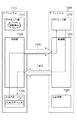
図4は、プロセッサ部12100が入出力部11200内の入出力デバイス11210をアクセスするデータを生成したときと、入出力デバイス11210がそのアクセスデータに対する応答データを生成したときのデータの流れを示している。ロックステップ非同期の状態にあるので、制御部12300は、入出力部11200内の入出力デバイス11210宛のデータをプロセッサ部12100から受信すると、受信したデータを信号伝送路13000を介して制御部11300へ送信する。また制御部11300は、受信したデータを入出力部11200の入出力デバイス11210へ送信する。
FIG. 4 shows a data flow when the
入出力デバイス11210は、上記データを受信し、上記データに応じた処理を行い、その処理結果を応答データとして生成し、制御部11300へ送信する。プロセッサ部11100が稼働していないロックステップ非同期の状態にあるので、制御部11300は、入出力デバイス11210からのデータを受信すると、信号伝送路13000を介して制御部12300へ転送する。制御部12300は、この転送されてきたデータをプロセッサ部12100へさらに転送する。
The input /
このように、プロセッサ部11100、12100がロックステップ非同期の状態にある場合、プロセッサ部12100から入出力デバイス11210宛のデータそのものが信号伝送路13000に送信される。
As described above, when the
図5は、プロセッサ部12100が入出力部12200内の入出力デバイス12210をアクセスするデータを生成したときと、入出力デバイス12210がそのアクセスデータに対する応答データを生成したときのデータの流れを示している。制御部12300は、入出力部12200内の入出力デバイス12210宛のデータをプロセッサ部12100から受信すると、そのデータを入出力部12200の入出力デバイス12210へ送信する。プロセッサ部11100が稼働していないロックステップ非同期の状態にあるので、制御部12300は信号伝送路13000への送信は行わない。
FIG. 5 shows a data flow when the
入出力デバイス12210は、上記データを受信し、上記データに応じた処理を行い、その処理結果を応答データとして生成し、制御部12300へ送信する。制御部12300は、入出力デバイス12210からのデータを受信すると、プロセッサ部12100へ転送する。プロセッサ部11100が稼働していないロックステップ非同期の状態にあるので、制御部12300は信号伝送路13000への送信は行わない。
The input /
以上説明したように本実施形態によれば、サブシステム間を接続する信号伝送路13000を流れるデータ量を低減しつつ、フォールトトレラントシステムをロックステップ同期の状態およびロックステップ非同期の状態の双方の状態で動作させることができる。
As described above, according to the present embodiment, the fault tolerant system is in both the lock step synchronous state and the lock step asynchronous state while reducing the amount of data flowing through the
その理由は、制御部11300、12300は、プロセッサ部11100、12100がロックステップ同期の状態にあるときは、自サブシステムのプロセッサ部から入出力部へアクセスされるデータから生成した誤り検出用データの他サブシステムへの送信を行い、他方、プロセッサ部11100、12100がロックステップ非同期の状態にあるときは、自サブシステムのプロセッサ部から入出力部へアクセスされるデータの他サブシステムへの送信を行うためである。
[第2の実施形態]
次に本発明の第2の実施形態について説明する。まず、本実施形態が解決しようとする課題について説明する。
The reason is that, when the
[Second Embodiment]
Next, a second embodiment of the present invention will be described. First, problems to be solved by this embodiment will be described.
特許文献1〜3に詳細は記載されていないが、例えば特許文献4の図1等に示されるように、フォールトトレラントシステムを構成する冗長化されたサブシステム間を接続するクロスリンクは、例えば本発明に関連する第2のフォールトトレラントシステムの構成図である図17に示すように、以下の4つの信号伝送路(リンク)で構成されている。
Although details are not described in
(1)モジュール1のCPUサブシステム10からモジュール2のIOサブシステム21へアクセスするデータを転送するための信号伝送路L1
(2)モジュール1のIOサブシステム11からモジュール2のCPUサブシステム20へアクセスするデータを転送するための信号伝送路L2
(3)モジュール2のCPUサブシステム20からモジュール1のIOサブシステム11へアクセスするデータを転送するための信号伝送路L3
(4)モジュール2のIOサブシステム21からモジュール1のCPUサブシステム10へアクセスするデータを転送するための信号伝送路L4
(1) A signal transmission path L1 for transferring data accessed from the
(2) A signal transmission path L2 for transferring data to be accessed from the
(3) A signal transmission path L3 for transferring data accessed from the
(4) Signal transmission path L4 for transferring data to be accessed from the
CPUサブシステム10、20がロックステップ動作している場合、信号伝送路L1、L3には、プロセッサ100、200からftチップセット110、210へ送信されるパケット量と同じ量のパケットが流れ、信号伝送路L2、L4には、IOデバイス130、230からftチップセット110、210を通じてプロセッサ100、200へ送信されるパケット量と同じ量のパケットが流れる。即ち、モジュール間リンクの帯域は、プロセッサとftチップセット間のリンクの帯域と同等になるように設計されている。例えば、プロセッサとftチップセットとの間がPCI−express5.0GT/sx4で接続されている場合、自系のCPUサブシステムと他系のIOサブシステムの間も、PCI−express5.0GT/sx4と同等のデータ転送帯域を持つリンクで接続されている。
When the
近年、より高いIO性能が要求されるのに従い、プロセッサとftチップセット間のリンクに必要となる帯域も増加している。その結果、モジュール間リンクにもより広い帯域が必要となり、そのためには、モジュール間リンクの転送速度を高速化するか、リンク幅を広げる必要がある。しかし、モジュール間リンクの転送速度を高速化するとシグナルインテグリティの検証のためのコストが増加し、リンク幅を広げるとftチップセットのコストが大きくなる。そのため、コストの増加を抑えるために、モジュール間リンクに必要となる帯域を広げることなく、より高いIO性能を実現する方法が必要となる。 In recent years, as higher IO performance is required, the bandwidth required for the link between the processor and the ft chipset is also increasing. As a result, a wider bandwidth is also required for the inter-module link. For this purpose, it is necessary to increase the transfer speed of the inter-module link or widen the link width. However, increasing the transfer speed of the inter-module link increases the cost for verifying signal integrity, and increasing the link width increases the cost of the ft chipset. Therefore, in order to suppress the increase in cost, a method for realizing higher IO performance without expanding the bandwidth required for the inter-module link is required.
本発明に関連する第1の関連技術では、パケットそのものでなくパケットから生成したチェックサムをクロスリンクを介して他サブシステムへ送信する一方、上記生成したチェックサムとクロスリンクを介して他サブシステムから受信したチェックサムとを比較してサブシステム間の処理の不一致を検知している。従って、上記第1の関連技術を図17の本発明に関連する第2のフォールトトレラントシステムに適用すれば、CPUサブシステム10、20がロックステップ動作している際に信号伝送路L1、L3を流れるデータ量を、パケットそのものを送信する場合に比べて低減することが可能である。しかしながら、信号伝送路L1、L3は、CPUサブシステム10、20がロックステップ動作している場合に使用される以外に、ロックステップ動作していない場合にも使用される。例えば信号伝送路L1は、CPUサブシステム20が停止している状態で、CPUサブシステム10から他系のIOサブシステム230を制御するために、プロセッサ100で生成したパケットそのものを流すために使用される。また信号伝送路L3は、CPUサブシステム10が停止している状態で、CPUサブシステム20から他系のIOサブシステム130を制御するために、プロセッサ200で生成したパケットそのものを流すために使用される。従って、ロックステップ動作時の必要帯域を狭くしただけでは、信号伝送路L1、L3に必要となる帯域を削減することはできない。
In the first related technology related to the present invention, the checksum generated from the packet, not the packet itself, is transmitted to the other subsystem via the crosslink, while the other subsystem is transmitted via the crosslink to the generated checksum. Compared with the checksum received from the server, the processing mismatch between the subsystems is detected. Therefore, if the first related technique is applied to the second fault tolerant system related to the present invention shown in FIG. 17, the signal transmission lines L1 and L3 are connected when the
本実施形態の目的は、上述した課題、すなわち、サブシステム間を相互に接続する信号伝送路に必要となる帯域を削減することは困難である、という課題を解決するフォールトトレラントシステムを提供することにある。 An object of the present embodiment is to provide a fault tolerant system that solves the above-described problem, that is, it is difficult to reduce the bandwidth required for signal transmission paths that interconnect subsystems. It is in.
図6を参照すると、本発明の第2の実施形態にかかるフォールトトレラントシステム1000は、互いに同一のハードウェアで構成された2つのサブシステム1100、1200を備えている。
Referring to FIG. 6, a fault-tolerant system 1000 according to the second embodiment of the present invention includes two
サブシステム1100は、プロセッサ部1110、このプロセッサ部1110に接続される入出力部1120、および、プロセッサ部1110と入出力部1120間に接続される制御部1130を有する。また、サブシステム1200は、プロセッサ部1210、このプロセッサ部1210に接続される入出力部1220、および、プロセッサ部1210と入出力部1220間に接続される制御部1230を有する。さらに、制御部1130、1230を介してサブシステム1100とサブシステム1200間を互いに接続する2本の信号伝送路1300、1400が設けられている。
The
プロセッサ部1110とプロセッサ部1210は、サブシステム1100とサブシステム1200とがロックステップ動作している状態(ロックステップ同期の状態)で動作可能であると共に、サブシステム1100とサブシステム1200とがロックステップ動作していない状態(ロックステップ非同期の状態)で動作可能である。
The processor unit 1110 and the
制御部1130、1230は、以下のような機能を有する。
The
まず、制御部1130、1230は、プロセッサ部1110、1210がロックステップ同期の状態にあるときは、制御部1130、1230を介してサブシステム1100のプロセッサ部1110からサブシステム1200の入出力部1220へアクセスされるデータから制御部1130によって生成された誤り検出用データの送信と、サブシステム1100の入出力部1120からサブシステム1200のプロセッサ部1210へアクセスされるデータの送信とで、信号伝送路1300を共用する制御を行う。同じくプロセッサ部1110、1210がロックステップ同期の状態にあるときは、制御部1130、1230を介してサブシステム1200のプロセッサ部1210からサブシステム1100の入出力部1120へアクセスされるデータから制御部1230によって生成された誤り検出用データの送信と、サブシステム1200の入出力部1220からサブシステム1100のプロセッサ部1110へアクセスされるデータの送信とで信号伝送路1400を共用する制御を行う。
First, the
ここで、誤り検出用データの種類およびその生成方法は、任意である。例えば、プロセッサ部から入出力部へアクセスされるデータが本来のデータ以外にCRC(Cyclic Redundancy Code)を有する場合、このCRCを上記誤り検出用データとして使用して良い。また、プロセッサ部から入出力部へアクセスされるデータに基づいてチェックサムを算出し、この算出したチェックサムを上記誤り検出用データとして使用して良い。 Here, the type of error detection data and the generation method thereof are arbitrary. For example, when the data accessed from the processor unit to the input / output unit has a CRC (Cyclic Redundancy Code ) in addition to the original data, this CRC may be used as the error detection data. Further, a checksum may be calculated based on data accessed from the processor unit to the input / output unit, and the calculated checksum may be used as the error detection data.
他方、プロセッサ部1110、1210がロックステップ非同期の状態にあるときは、制御部1130、1230は、制御部1130、1230を介してサブシステム1100のプロセッサ部1110からサブシステム1200の入出力部1220へアクセスされるデータの送信と、サブシステム1100の入出力部1120からサブシステム1200のプロセッサ部1210へアクセスされるデータの送信とのうちの何れか一方で、信号伝送路1300を使用する制御を行う。同じくプロセッサ部1110、1210がロックステップ非同期の状態にあるときは、制御部1130、1230を介してサブシステム1200のプロセッサ部1210からサブシステム1100の入出力部1120へアクセスされるデータの送信と、サブシステム1200の入出力部1220からサブシステム1100のプロセッサ部1110へアクセスされるデータの送信とのうちの何れか一方で、信号伝送路1400を使用する制御を行う。
On the other hand, when the
すなわち、プロセッサ部1110、1210がロックステップ非同期の状態にあるときは、主として、何れか一方のプロセッサ部が停止している。仮にプロセッサ部1210が停止しているとすると、入出力部1120、1220へのアクセスはプロセッサ部1110が担うことになる。このため、信号伝送路1300は、プロセッサ部1110から入出力部1220へアクセスするデータの送信に使用され、信号伝送路1400は、入出力部1220からプロセッサ部1110へアクセスするデータの送信に使用される。プロセッサ部1210は停止しているので、プロセッサ部1210から信号伝送路1400を通じて入出力部1120へアクセスするデータを送信することはなく、また入出力部1120から信号伝送路1300を通じてプロセッサ部1210へアクセスするデータを送信することはない。
That is, when the
次に本実施形態に係るフォールトトレラントシステム1000の動作を説明する。 Next, the operation of the fault tolerant system 1000 according to the present embodiment will be described.
まず、プロセッサ部1110、1210がロックステップ同期の状態にあるときの動作を説明する。
First, the operation when the
図7は、プロセッサ部1110とプロセッサ部1210とが入出力部1120内の入出力デバイス1121をアクセスするデータを生成したときと、入出力デバイス1121がそのアクセスデータに対する応答データを生成したときのデータの流れを示している。ロックステップ同期の状態にあるので、制御部1130は、入出力部1120内の入出力デバイス1121宛のデータをプロセッサ部1110から受信すると、そのデータから誤り検出用データを作成し、元のデータと上記作成した誤り検出用データとを制御部1130内部のバッファに蓄積して一時的に保存する。他方、制御部1230は、入出力デバイス1121宛のデータをプロセッサ部1210から受信すると、そのデータから誤り検出用データを作成し、信号伝送路1400を介して制御部1130へ送信する。制御部1130は、バッファに蓄積されている誤り検出用データと信号伝送路1400を介して制御部1230から受信した誤り検出用データとを比較する。そして、双方の誤り検出用データが一致した場合に限り、バッファに保持している入出力デバイス1121宛のデータを入出力部1120の入出力デバイス1121へ送信する。これにより、双方の誤り検出用データが一致しないような不正な状況の下で入出力デバイス1121がアクセスされる事態が回避される。
FIG. 7 shows data when the processor unit 1110 and the
入出力デバイス1121は、上記データを受信し、上記データに応じた処理を行い、その処理結果を応答データとして生成し、制御部1130へ送信する。ロックステップ同期の状態にあるので、制御部1130は、入出力デバイス1121からのデータを受信すると、プロセッサ部1110へ転送すると共に、信号伝送路1300を介して制御部1230へ転送する。制御部1230は、この転送されてきたデータをプロセッサ部1210へさらに転送する。
The input / output device 1121 receives the data, performs processing according to the data, generates a processing result as response data, and transmits the response data to the
このように、プロセッサ部1110、1210がロックステップ同期の状態にある場合、プロセッサ部1210から入出力デバイス1121宛のデータは信号伝送路1400に送信されず、そのデータから生成された誤り検出用データが信号伝送路1400に送信される。他方、信号伝送路1300には、入出力デバイス1121が生成したデータが送信される。
As described above, when the
図8は、プロセッサ部1110とプロセッサ部1210とが入出力部1220内の入出力デバイス1221をアクセスするデータを生成したときと、入出力デバイス1221がそのアクセスデータに対する応答データを生成したときのデータの流れを示している。ロックステップ同期の状態にあるので、制御部1230は、入出力部1220内の入出力デバイス1221宛のデータをプロセッサ部1210から受信すると、そのデータから誤り検出用データを作成し、元のデータと上記作成した誤り検出用データとを制御部1230内部のバッファに蓄積して一時的に保存する。他方、制御部1130は、入出力デバイス1221宛のデータをプロセッサ部1110から受信すると、そのデータから誤り検出用データを作成し、信号伝送路1300を介して制御部1230へ送信する。制御部1230は、バッファに蓄積されている誤り検出用データと信号伝送路1300を介して制御部1130から受信した誤り検出用データとを比較する。そして、双方の誤り検出用データが一致した場合に限り、バッファに保持している入出力デバイス1221宛のデータを入出力部1220の入出力デバイス1221へ送信する。これにより、双方の誤り検出用データが一致しないような不正な状況の下で入出力デバイス1221がアクセスされる事態が回避される。
FIG. 8 shows data when the processor unit 1110 and the
入出力デバイス1221は、上記データを受信し、上記データに応じた処理を行い、その処理結果を応答データとして生成し、制御部1230へ送信する。ロックステップ同期の状態にあるので、制御部1230は、入出力デバイス1221からのデータを受信すると、プロセッサ部1210へ転送すると共に、信号伝送路1400を介して制御部1130へ転送する。制御部1130は、この転送されてきたデータをプロセッサ部1110へさらに転送する。
The input / output device 1221 receives the data, performs processing according to the data, generates a processing result as response data, and transmits the response data to the
このように、プロセッサ部1110、1210がロックステップ同期の状態にある場合、プロセッサ部1110から入出力デバイス1221宛のデータは信号伝送路1300に送信されず、そのデータから生成された誤り検出用データが信号伝送路1300に送信される。他方、信号伝送路1400には、入出力デバイス1221が生成したデータが送信される。
As described above, when the
現用で使用する入出力デバイスが入出力部1120と入出力部1220とに分散している場合、図7に示したような動作と図8に示したような動作とが並行して行われる。その結果、信号伝送路1300、1400に流れる誤り検出用データのデータ量の最大値をX、入出力部で生成されるデータ量の最大値をYとすると、信号伝送路1300、1400に流れるデータ量の最大値はX+Yとなる。
When the input / output devices used in the current operation are distributed in the input /
次に、プロセッサ部1110、1210がロックステップ非同期の状態にあるときの動作を説明する。例として、プロセッサ部1110が障害など何らかの理由で稼働を停止し、プロセッサ部1210が稼働している状態を想定する。このとき、入出力部1120および入出力部1220をアクセスするデータを生成するのは、プロセッサ部1210のみである。
Next, the operation when the
図9は、プロセッサ部1210が入出力部1120内の入出力デバイス1121をアクセスするデータを生成したときと、入出力デバイス1121がそのアクセスデータに対する応答データを生成したときのデータの流れを示している。ロックステップ非同期の状態にあるので、制御部1230は、入出力部1120内の入出力デバイス1121宛のデータをプロセッサ部1210から受信すると、受信したデータを信号伝送路1400を介して制御部1130へ送信する。また制御部1130は、受信したデータを入出力部1120の入出力デバイス1121へ送信する。
FIG. 9 shows a data flow when the
入出力デバイス1121は、上記データを受信し、上記データに応じた処理を行い、その処理結果を応答データとして生成し、制御部1130へ送信する。プロセッサ部1110が稼働していないロックステップ非同期の状態にあるので、制御部1130は、入出力デバイス1121からのデータを受信すると、信号伝送路1300を介して制御部1230へ転送する。制御部1230は、この転送されてきたデータをプロセッサ部1210へさらに転送する。
The input / output device 1121 receives the data, performs processing according to the data, generates a processing result as response data, and transmits the response data to the
このように、プロセッサ部1110、1210がロックステップ非同期の状態にある場合、プロセッサ部1210から入出力デバイス1121宛のデータそのものが信号伝送路1400に送信される。他方、信号伝送路1300には、入出力デバイス1121が生成したデータが送信される。
In this way, when the
図10は、プロセッサ部1210が入出力部1220内の入出力デバイス1221をアクセスするデータを生成したときと、入出力デバイス1221がそのアクセスデータに対する応答データを生成したときのデータの流れを示している。制御部1230は、入出力部1220内の入出力デバイス1221宛のデータをプロセッサ部1210から受信すると、そのデータを入出力部1220の入出力デバイス1221へ送信する。プロセッサ部1110が稼働していないロックステップ非同期の状態にあるので、制御部1230は信号伝送路1400への送信は行わない。
FIG. 10 shows a data flow when the
入出力デバイス1221は、上記データを受信し、上記データに応じた処理を行い、その処理結果を応答データとして生成し、制御部1230へ送信する。制御部1230は、入出力デバイス1221からのデータを受信すると、プロセッサ部1210へ転送する。プロセッサ部1110が稼働していないロックステップ非同期の状態にあるので、制御部1230は信号伝送路1400への送信は行わない。
The input / output device 1221 receives the data, performs processing according to the data, generates a processing result as response data, and transmits the response data to the
このように、プロセッサ部1110、1210がロックステップ非同期の状態にある場合、プロセッサ部1210から入出力デバイス1221をアクセスする際には信号伝送路1400は使用されない。また入出力デバイス1221がデータを生成した際も、信号伝送路1400は使用されない。
As described above, when the
現用で使用する入出力デバイスが入出力部1120と入出力部1220とに分散している場合、図9に示したような動作と図10に示したような動作とが並行して行われる。プロセッサ部から入出力部をアクセスするデータのデータ量の最大値は、入出力部で生成されるデータ量の最大値とほぼ同じである。従って、信号伝送路1300、1400に流れるデータ量の最大値はYとなる。
When the input / output devices used in the current operation are distributed in the input /
次に、比較のために、図13〜図16に示すように、サブシステム1100、1200間を以下のような4つの信号伝送路で接続した本発明に関連する第1のフォールトトレラントシステムについて説明する。
Next, for comparison, a first fault tolerant system related to the present invention in which the
(1)サブシステム1100のプロセッサ部1110からサブシステム1200の入出力部1220へアクセスするデータを転送するための信号伝送路1310
(2)サブシステム1100の入出力部1120からサブシステム1200のプロセッサ部1210へアクセスするデータを転送するための信号伝送路1320
(3)サブシステム1200のプロセッサ部1210からサブシステム1100の入出力部1120へアクセスするデータを転送するための信号伝送路1410
(4)サブシステム1200の入出力部1220からサブシステム1100のプロセッサ部1110へアクセスするデータを転送するための信号伝送路1420
(1) A
(2)
(3) A
(4)
まず、プロセッサ部1110、1210がロックステップ同期の状態にあるときの動作を説明する。
First, the operation when the
図13は、プロセッサ部1110とプロセッサ部1210とが入出力部1120内の入出力デバイス1121をアクセスするデータを生成したときと、入出力デバイス1121がそのアクセスデータに対する応答データを生成したときのデータの流れを示している。ロックステップ同期の状態にあるので、制御部1130は、入出力部1120内の入出力デバイス1121宛のデータをプロセッサ部1110から受信すると、そのデータからチェックサムを作成し、元のデータと上記作成したチェックサムとを制御部1130内部のバッファに蓄積して一時的に保存する。他方、制御部1230は、入出力デバイス1121宛のデータをプロセッサ部1210から受信すると、そのデータからチェックサムを作成し、信号伝送路1410を介して制御部1130へ送信する。制御部1130は、バッファに蓄積されているチェックサムと信号伝送路1410を介して制御部1230から受信したチェックサムとを比較する。そして、双方のチェックサムが一致した場合に限り、バッファに保持している入出力デバイス1121宛のデータを入出力部1120の入出力デバイス1121へ送信する。
FIG. 13 shows data when the processor unit 1110 and the
入出力デバイス1121は、上記データを受信し、上記データに応じた処理を行い、その処理結果を応答データとして生成し、制御部1130へ送信する。ロックステップ同期の状態にあるので、制御部1130は、入出力デバイス1121からのデータを受信すると、プロセッサ部1110へ転送すると共に、信号伝送路1320を介して制御部1230へ転送する。制御部1230は、この転送されてきたデータをプロセッサ部1210へさらに転送する。
The input / output device 1121 receives the data, performs processing according to the data, generates a processing result as response data, and transmits the response data to the
図14は、プロセッサ部1110とプロセッサ部1210とが入出力部1220内の入出力デバイス1221をアクセスするデータを生成したときと、入出力デバイス1221がそのアクセスデータに対する応答データを生成したときのデータの流れを示している。ロックステップ同期の状態にあるので、制御部1230は、入出力部1220内の入出力デバイス1221宛のデータをプロセッサ部1210から受信すると、そのデータからチェックサムを作成し、元のデータと上記作成したチェックサムとを制御部1230内部のバッファに蓄積して一時的に保存する。他方、制御部1130は、入出力デバイス1221宛のデータをプロセッサ部1110から受信すると、そのデータからチェックサムを作成し、信号伝送路1310を介して制御部1230へ送信する。制御部1230は、バッファに蓄積されているチェックサムと信号伝送路1310を介して制御部1130から受信したチェックサムとを比較する。そして、双方のチェックサムが一致した場合に限り、バッファに保持している入出力デバイス1221宛のデータを入出力部1220の入出力デバイス1221へ送信する。
FIG. 14 shows data when the processor unit 1110 and the
入出力デバイス1221は、上記データを受信し、上記データに応じた処理を行い、その処理結果を応答データとして生成し、制御部1230へ送信する。ロックステップ同期の状態にあるので、制御部1230は、入出力デバイス1221からのデータを受信すると、プロセッサ部1210へ転送すると共に、信号伝送路1420を介して制御部1130へ転送する。制御部1130は、この転送されてきたデータをプロセッサ部1110へさらに転送する。
The input / output device 1221 receives the data, performs processing according to the data, generates a processing result as response data, and transmits the response data to the
現用で使用する入出力デバイスが入出力部1120と入出力部1220とに分散している場合、図13に示したような動作と図14に示したような動作とが並行して行われる。その結果、信号伝送路1310、1320、1410、1420に流れるデータ量の最大値はYとなる。
When the input / output devices that are currently used are distributed in the input /
次に、プロセッサ部1110、1210がロックステップ非同期の状態にあるときの動作を説明する。例として、プロセッサ部1110が障害など何らかの理由で稼働を停止し、プロセッサ部1210が稼働している状態を想定する。このとき、入出力部1120および入出力部1220をアクセスするデータを生成するのは、プロセッサ部1210のみである。
Next, the operation when the
図15は、プロセッサ部1210が入出力部1120内の入出力デバイス1121をアクセスするデータを生成したときと、入出力デバイス1121がそのアクセスデータに対する応答データを生成したときのデータの流れを示している。ロックステップ非同期の状態にあるので、制御部1230は、入出力部1120内の入出力デバイス1121宛のデータをプロセッサ部1210から受信すると、受信したデータを信号伝送路1410を介して制御部1130へ送信する。また制御部1130は、受信したデータを入出力部1120の入出力デバイス1121へ送信する。
FIG. 15 shows a data flow when the
入出力デバイス1121は、上記データを受信し、上記データに応じた処理を行い、その処理結果を応答データとして生成し、制御部1130へ送信する。プロセッサ部1110が稼働していないロックステップ非同期の状態にあるので、制御部1130は、入出力デバイス1121からのデータを受信すると、信号伝送路1320を介して制御部1230へ転送する。制御部1230は、この転送されてきたデータをプロセッサ部1210へさらに転送する。
The input / output device 1121 receives the data, performs processing according to the data, generates a processing result as response data, and transmits the response data to the
図16は、プロセッサ部1210が入出力部1220内の入出力デバイス1221をアクセスするデータを生成したときと、入出力デバイス1221がそのアクセスデータに対する応答データを生成したときのデータの流れを示している。制御部1230は、入出力部1220内の入出力デバイス1221宛のデータをプロセッサ部1210から受信すると、そのデータを入出力部1220の入出力デバイス1221へ送信する。プロセッサ部1110が稼働していないロックステップ非同期の状態にあるので、制御部1230は信号伝送路1410への送信は行わない。
FIG. 16 shows a data flow when the
入出力デバイス1221は、上記データを受信し、上記データに応じた処理を行い、その処理結果を応答データとして生成し、制御部1230へ送信する。制御部1230は、入出力デバイス1221からのデータを受信すると、プロセッサ部1210へ転送する。プロセッサ部1110が稼働していないロックステップ非同期の状態にあるので、制御部1230は信号伝送路1420への送信は行わない。
The input / output device 1221 receives the data, performs processing according to the data, generates a processing result as response data, and transmits the response data to the
このように、プロセッサ部1110、1210がロックステップ非同期の状態にある場合、プロセッサ部1210から入出力デバイス1221をアクセスする際には信号伝送路1410は使用されない。また入出力デバイス1221がデータを生成した際も、信号伝送路1420は使用されない。
As described above, when the
現用で使用する入出力デバイスが入出力部1120と入出力部1220とに分散している場合、図15に示したような動作と図16に示したような動作とが並行して行われる。従って、信号伝送路1320、1410に流れるデータ量の最大値はYとなる。同様に、プロセッサ部1110でなくプロセッサ部1210が障害等により停止した場合には、信号伝送路1310、1420に流れるデータ量の最大値はYとなる。
When the input / output devices used in the current operation are distributed in the input /
以上の結果、サブシステム1100、1200間を図13〜図16に示すように4本の信号伝送路で接続したフォールトトレラントシステムにおいては、各信号伝送路に必要となる帯域はYとなる。従って、サブシステム全体では、サブシステム1100からサブシステム1200へデータを送信するために必要となる帯域、および、サブシステム1200からサブシステム1100へデータを送信するために必要となる帯域は、それぞれ2Yとなる。
As a result, in the fault tolerant system in which the
これに対して、サブシステム1100、1200間を図7〜図10に示すように2本の信号伝送路1300、1400で接続し、一方のサブシステムのプロセッサ部から他方のサブシステムの入出力部へアクセスするデータと一方のサブシステムの入出力部から他方のサブシステムのプロセッサ部へアクセスするデータとで同じ信号伝送路を共有する本実施形態に係るフォールトトレラントシステムでは、サブシステム1100からサブシステム1200へデータを送信するために必要となる帯域、および、サブシステム1200からサブシステム1100へデータを送信するために必要となる帯域は、それぞれX+Yとなる。ここで、XはYより十分に小さい。従って、本実施形態によれば、サブシステム間を相互に接続する信号伝送路に必要となる帯域を大幅に削減することができる。
On the other hand, the
なお、プロセッサ部1110、1210がロックステップ非同期の状態にあるときに、プロセッサ部1110、1210の双方を独立して稼働させ、プロセッサ部1110に他系の入出力部1220との間でデータの授受を行わせ、且つ、プロセッサ部1210に他系の入出力部1120との間でデータの授受を行わせることは、理論的には可能である。そして、その際には信号伝送路1300、1400に必要な帯域は2Yとなる。従って、信号伝送路1300、1400の帯域をX+Yに設定した場合、上述したような動作は信号伝送路の帯域不足によって実現困難になるが、実用面では全く問題とはならない。何故ならば、上述したような動作形態は実際の運用では必要性がないためである。
When the
[第3の実施形態]
次に本発明の第3の実施形態について詳細に説明する。
[本実施形態が解決しようとする課題]
まず、図17を参照して本実施形態が解決しようとする課題について説明する。図17は、2つのモジュールをロックステップ動作させる本発明に関連する第2のフォールトトレラントシステムの構成を示している。このフォールトトレラントシステムでは、自モジュールのCPUサブシステムと他モジュールのIOサブシステムとの間、また自モジュールのIOサブシステムと他モジュールのCPUサブシステムの間が、モジュール間リンクにより双方向接続されている。このとき、モジュール間リンクの帯域は、プロセッサとftチップセット間のリンクの帯域と同等になるように設計されている。例えば、プロセッサとftチップセットとの間がPCI−express5.0GT/sx4で接続されている場合、自系のCPUサブシステムと他系のIOサブシステムの間も、PCI−express5.0GT/sx4と同等のデータ転送帯域を持つリンクで接続されている。
[Third embodiment]
Next, a third embodiment of the present invention will be described in detail.
[Problems to be solved by this embodiment]
First, a problem to be solved by the present embodiment will be described with reference to FIG. FIG. 17 shows the configuration of the second fault tolerant system related to the present invention in which two modules are operated in a lock step. In this fault tolerant system, the own module's CPU subsystem and another module's IO subsystem, and the own module's IO subsystem and the other module's CPU subsystem are bi-directionally connected by an inter-module link. Yes. At this time, the bandwidth of the link between modules is designed to be equal to the bandwidth of the link between the processor and the ft chipset. For example, when the processor and the ft chipset are connected with PCI-express 5.0 GT / sx4, the PCI-express 5.0 GT / sx4 is also connected between the local CPU subsystem and the other IO subsystem. Connected with a link having the same data transfer bandwidth.
近年、より高いIO性能が要求されるのに従い、プロセッサとftチップセット間のリンクに必要となる帯域も増加している。その結果、モジュール間リンクにもより高い帯域が必要となるが、帯域を高めるためには、転送速度を高速化させるか、リンク幅を増やす必要がある。しかし、転送速度を高速化させるとシグナルインテグリティの検証の為のコストが増加し、リンク幅を増やすとftチップセットのコストが大きくなる。その為、コストの増加を抑えるために、モジュール間リンクに必要となる帯域を増やすことなく、より高いIO性能を実現する方法が必要となる。 In recent years, as higher IO performance is required, the bandwidth required for the link between the processor and the ft chipset is also increasing. As a result, a higher bandwidth is also required for the inter-module link. However, in order to increase the bandwidth, it is necessary to increase the transfer speed or increase the link width. However, increasing the transfer rate increases the cost for verifying signal integrity, and increasing the link width increases the cost of the ft chipset. Therefore, in order to suppress the increase in cost, a method for realizing higher IO performance without increasing the bandwidth required for the inter-module link is required.
[本実施形態の概要]
本実施形態では、以下の2つの手段により上記課題を解決する。
[Overview of this embodiment]
In the present embodiment, the above-described problem is solved by the following two means.
1つ目の手段として、モジュール間リンクを共用化する。本発明に関連する第2のフォールトトレラントシステムでは、モジュール間リンクはモジュール1のCPUサブシステムからモジュール2のIOサブシステムへのリンク、モジュール1のIOサブシステムからモジュール2のCPUサブシステムへのリンク、モジュール2のCPUサブシステムからモジュール1のIOサブシステムへのリンク、モジュール2のIOサブシステムからモジュール1のCPUサブシステムへのリンクの、4つのリンクで構成されていた。一方、本実施形態による構成では、モジュール間リンクをモジュール1からモジュール2へのリンク、モジュール2からモジュール1へのリンクの2つのリンクに再構成し、モジュール1のCPUサブシステムからモジュール2のIOサブシステムへのデータ転送と、モジュール1のIOサブシステムからモジュール2のCPUサブシステムへのデータ転送でモジュール間リンクを共用する。
As a first means, the link between modules is shared. In the second fault tolerant system related to the present invention, the inter-module link is a link from the
2つ目の手段として、CPUサブシステムがロックステップ動作している場合に、反対側のモジュールのIOサブシステムへのデータ転送量を削減する。本発明に関連する第2のフォールトトレラントシステムでは、CPUサブシステムはプロセッサから受信したパケットの宛先を確認し、モジュール1のIOサブシステム、またはモジュール2のIOサブシステムにパケット全体を転送していた。IOサブシステムはモジュール1のCPUサブシステムから受信したパケットと、モジュール2のCPUサブシステムから受信したパケットが一致していることを確認し、IOデバイスにそのパケットを転送していた。一方、本実施形態による構成では、CPUサブシステムはプロセッサから受信したパケットの宛先を確認し、宛先が反対側のモジュールのIOデバイスであった場合、かつCPUサブシステムがロックステップ動作している場合には、パケット全体を送信せずに、パケットの一部(または後述する実施形態のようにパケット情報やパケットを受信した時刻情報から生成したチェックサム等であってもよい)を送信する。一例としてパケットに含まれるCRCのみを送信する場合、IOサブシステムは、モジュール1のCPUサブシステムから受信したCRCと、モジュール2のCPUサブシステムから受信したCRCとを比較し、一致した場合には、自系のCPUサブシステムから受信したパケットをIOデバイスに転送する。一方、パケットの宛先が自系のIOサブシステムであった場合、またはCPUサブシステムがロックステップ動作していない場合には、パケット全体をIOサブシステムに転送する。
As a second means, when the CPU subsystem is performing a lock step operation, the amount of data transferred to the IO subsystem of the opposite module is reduced. In the second fault tolerant system related to the present invention, the CPU subsystem confirms the destination of the packet received from the processor, and transfers the entire packet to the
[本実施形態の構成]
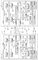
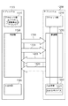
図11を参照すると、本発明の第3の実施形態として、モジュール1とモジュール2から構成されるフォールトトレラントシステムが示されている。モジュール1とモジュール2とは、モジュール間リンク30によって相互に接続されている。モジュール間リンク30は、モジュール1からモジュール2への送信に使用する信号伝送路31と、その逆にモジュール2からモジュール1への送信に使用する信号伝送路32との2つの信号伝送路で構成されている。
[Configuration of this embodiment]
Referring to FIG. 11, a fault tolerant
モジュール1は、プロセッサ100、ftチップセット110、IOデバイス130で構成される。プロセッサ100は、図示しないCPUやメモリ等に加えて、パケット送信部101とパケット受信部102を有する。IOデバイス130は、図示しないIOデバイス等に加えて、パケット送信部131とパケット受信部132を有する。ftチップセット110は、パケット受信部111、パケット送信部112、セレクタ113、CRC抽出器115、送信部116、受信部117、バッファ118、バッファ119、バッファ120、バッファ121、比較器122、セレクタ123、パケット送信部124、パケット受信部125から構成される。また、ftチップセット110は、モジュール間リンク30に接続されている。
The
モジュール2は、モジュール1と同じ構成を有する。すなわち、モジュール2は、プロセッサ200、ftチップセット210、IOデバイス230で構成される。プロセッサ200は、図示しないCPUやメモリ等に加えて、パケット送信部201とパケット受信部202を有する。IOデバイス230は、図示しないIOデバイス等に加えて、パケット送信部231とパケット受信部232を有する。ftチップセット210は、パケット受信部211、パケット送信部212、セレクタ213、CRC抽出器215、送信部216、受信部217、バッファ218、バッファ219、バッファ220、バッファ221、比較器222、セレクタ223、パケット送信部224、パケット受信部225から構成される。また、ftチップセット210は、モジュール間リンク30に接続されている。
モジュール1とモジュール2は同じ構成なので、以下では、主にモジュール1について説明する。
Since the
プロセッサ100は、IOデバイス130、IOデバイス230に対するパケットを生成する。パケットは、例えば、宛先の情報、送信元の情報、データ、CRC、およびその他の情報を有する。プロセッサ100が生成したパケットは、パケット送信部101により、パケットの中継を行うftチップセット110に送信される。また、パケット受信部102は、ftチップセット110からパケットを受信する。
The
IOデバイス130は、プロセッサ100、プロセッサ200に対するパケットを生成する。生成されたパケットは、パケット受信部132により、パケットの中継を行うftチップセット110に送信される。また、パケット受信部131は、ftチップセット110からパケットを受信する。
The
ftチップセット110は、プロセッサ100、プロセッサ200、IOデバイス130、IOデバイス230から発行されたパケットの中継を行う。
The
パケット受信部111は、プロセッサ100から受信したパケットを出力する。またパケット受信部111は、プロセッサ100から受信したパケットの宛先を確認し、IOデバイス130宛てのパケットであった場合にはバッファ121に登録する。
The
パケット送信部112は、受信部117、またはパケット受信部125から受信したパケットを、プロセッサ100に送信する。
The
セレクタ113は、CPUサブシステムがロックステップ動作している場合には、CRC抽出器115の出力を選択し、CPUサブシステムがロックステップ動作していない場合には、パケット受信部111からの出力を選択する。
The
CRC抽出器115は、パケット受信部111から出力されるパケットからCRCを抽出し、セレクタ113に出力する。また、CRCをバッファ118に登録する。
The
送信部116は、セレクタ113から出力されるCRCまたはパケットを、モジュール間リンク30の信号伝送路31を介して、モジュール2のIOサブシステム21に送信する。また、送信部116は、パケット受信部125から受信したパケットも、信号伝送路31を介して、モジュール2のIOサブシステム21に送信する。
The
受信部117は、モジュール間リンク30の信号伝送路32を介してモジュール2のCPUサブシステム20から受信したCRCをバッファ119に登録する。また、受信部117は、信号伝送路32を介してモジュール2のCPUサブシステム20から受信したパケットをバッファ120に登録する。
The receiving
比較器122は、バッファ118とバッファ119から出力されるCRCを比較し、一致した場合には、バッファ121にパケットを出力するように指示する。
The
セレクタ123は、CPUサブシステムがロックステップ動作している場合、またCPUサブシステム10のみが稼働している場合には、バッファ121を選択する。CPUサブシステム20のみが稼働している場合には、バッファ120を選択する。
The
[本実施形態の動作]
CPUサブシステム10とCPUサブシステム20がロックステップ動作している場合と、ロックステップ動作していない場合とで動作が異なる。まず、CPUサブシステム10とCPUサブシステム20がロックステップ動作している場合の動作を説明する。
[Operation of this embodiment]
The operation differs depending on whether the
CPUサブシステムがロックステップ動作している場合には、プロセッサ100とプロセッサ200は、同じ時刻に同じパケットを生成する。ここで、生成されたパケットの宛先がIOデバイス130であるとする。生成されたパケットは、パケット送信部101、パケット送信部201を経由してパケット受信部111とパケット受信部211に受信される。パケット受信部111は、受信したパケットを出力し、バッファ121に登録する。また、CRC抽出器115は、受信したパケットのCRCを取り出し、バッファ118に登録する。
When the CPU subsystem is performing a lockstep operation, the
一方、パケット受信部211は、パケットの宛先がIOデバイス130宛てである場合には、バッファ221にパケットを登録しない。セレクタ213にはパケット受信部211が受信したパケットと、CRC抽出器215がパケットから取り出したCRCが入力されているが、CPUがロックステップ動作しているため、CRCを送信部216に送付する。送信部216は、CRCを信号伝送路32を介して受信部117に送信する。受信部117は、受信したCRCをバッファ119に登録する。比較器122は、バッファ118に登録されたCRCと、バッファ119に登録されたCRCとを比較し、一致している場合にはバッファ121に指示して、バッファ121に登録されているパケットを出力させる。セレクタ123は、バッファ121から受け取ったパケットをパケット送信部124に出力する。パケット送信部124は、受け取ったパケットをIOデバイス130に送信する。
On the other hand, the
次に、IOデバイス130がパケットを生成した場合の動作を説明する。CPUサブシステムがロックステップ動作している場合には、このパケットはプロセッサ100とプロセッサ200の両方に送信する必要がある。パケット送信部132は、IOデバイス130が生成したパケットをパケット受信部125に送信する。パケット受信部125は、受信したパケットをパケット送信部112と、送信部116に出力する。パケット送信部112は、受け取ったパケットをパケット送信部102に送信する。送信部116は、受け取ったパケットを信号伝送路31を介して受信部217に送信する。受信部217は、受信したパケットの宛先を確認し、パケット送信部212に出力する。パケット送信部212は、受け取ったパケットをパケット送信部202に送信する。
Next, an operation when the
このように、CPUサブシステム10とCPUサブシステム20がロックステップ動作している場合には、プロセッサからIOデバイス宛てのパケットはCRCのみがモジュール間リンク30上で送信され、IOデバイスからプロセッサ宛てのパケットはパケット全体がモジュール間リンク30上で送信される。
As described above, when the
次に、CPUサブシステム10とCPUサブシステム20がロックステップ動作していない場合の動作を説明する。ここでは、CPUサブシステム10が稼働しており、CPUサブシステム20は稼働していない場合の説明を行う。
Next, the operation when the
CPUサブシステム10のみが稼働しているため、IOデバイス130宛てのパケット、IOデバイス230宛てのパケットを発行するのはCPUサブシステム10のみである。まず、CPUサブシステム10がIOデバイス130宛てのパケットを発行した場合の説明を行う。プロセッサが発行したIOデバイス130宛てのパケットは、パケット送信部101、パケット受信部111を経由してバッファ121に入力される。ここで、CPUサブシステム10とCPUサブシステム20はロックステップ動作していない為、バッファ121に入力されたパケットは、セレクタ123、パケット送信部124を経由して、パケット受信部131により受信される。
Since only the
次に、CPUサブシステム10がIOデバイス230宛てのパケットを発行した場合の説明を行う。同様に、プロセッサが発行したパケットは、パケット送信部101、パケット受信部111を経由するが、宛先がIOデバイス230であるため、バッファ121には登録されない。その代わりに、IOデバイス230宛てのパケットは、セレクタ113、送信部116を経由して、信号伝送路31経由で受信部217により受信される。受信部217は、受信したパケットの宛先を確認し、IOデバイス230宛なので、バッファ220に登録する。登録されたパケットは、セレクタ223、パケット送信部224を経由して、パケット受信部231により受信される。このように、CPUサブシステム10とCPUサブシステム20がロックステップ動作していない場合、宛先が他系のIOデバイスであるパケットは、その全体がモジュール間リンク30上で送信される。
Next, the case where the
次に、IOデバイス130がパケットを生成した場合の動作を説明する。CPUサブシステム10のみが稼働しているため、このパケットはプロセッサ100にのみ送信する必要がある。IOデバイス130が生成したパケットは、パケット送信部132、パケット受信部125、パケット送信部112を経由して、パケット送信部102に受信される。
Next, an operation when the
次に、IOデバイス230がパケットを生成した場合の動作を説明する。CPUサブシステム10のみが稼働しているため、このパケットもプロセッサ100にのみ送信する必要がある。IOデバイス230が生成したパケットは、パケット送信部232、パケット受信部225、送信部216、信号伝送路32、受信部117、パケット送信部112を経由して、パケット送信部102に受信される。このように、CPUサブシステム10とCPUサブシステム20がロックステップ動作していない場合、IOデバイスが生成したパケットの宛先が他系のプロセッサである場合、パケット全体がモジュール間リンク30上で送信される。
Next, an operation when the
[本実施形態の効果]
本実施形態の効果として、モジュール間リンクに必要となる帯域を大幅に減少することが可能になる。その理由は以下の通りである。
[Effect of this embodiment]
As an effect of this embodiment, it is possible to significantly reduce the bandwidth required for the inter-module link. The reason is as follows.
本発明に関連する第2のフォールトトレラントシステムでは、CPUサブシステムがロックステップ動作しているかどうかにかかわらず、モジュール間リンク上でパケット全体を送信していた。その為、自系のCPUサブシステムから他系のIOサブシステムへのモジュール間リンクと、自系のIOサブシステムから他系のCPUサブシステムへのモジュール間リンクを独立して用意する必要があった。一方で、本実施形態によるシステムでは、CPUサブシステムがロックステップ動作している場合には、自系のCPUサブシステムから他系のIOサブシステムへはCRCのみを送付すれば良い。パケット全体のデータ量に対して、CRCのみのデータ量は数十分の一に抑えることが出来るため、自系のCPUサブシステムから他系のIOサブシステムへのデータ転送量が大幅に削減できる。一方、CPUサブシステムがロックステップ動作していない場合には、稼働しているCPUサブシステムから他系のIOサブシステムへはパケット全体を送信する必要があるが、稼働していないCPUサブシステムから他系のIOサブシステムへのデータ転送が不要である。その為、モジュール1からモジュール2、またはモジュール2からモジュール1全体で見た場合、モジュール間リンク上で転送されるデータ量は、CPUサブシステムがロックステップ動作している場合よりも、CRCの送信にかかる分だけ少ない。
In the second fault tolerant system associated with the present invention, the entire packet was transmitted over the inter-module link regardless of whether the CPU subsystem is in lockstep operation. Therefore, it is necessary to prepare an inter-module link from the own CPU subsystem to the other IO subsystem and an inter-module link from the own IO subsystem to the other CPU subsystem independently. It was. On the other hand, in the system according to the present embodiment, when the CPU subsystem performs a lock step operation, only the CRC needs to be sent from the own CPU subsystem to the other IO subsystem. Since the data amount of CRC only can be reduced to a few tenths of the total packet data amount, the data transfer amount from the own CPU subsystem to the other IO subsystem can be greatly reduced. . On the other hand, when the CPU subsystem is not performing the lockstep operation, it is necessary to transmit the entire packet from the operating CPU subsystem to the other IO subsystem. Data transfer to an IO subsystem of another system is not necessary. Therefore, when viewed from
以上より、本発明に関連する第2のフォールトトレラントシステムではパケット全体の送信に必要となる帯域をPとした場合、モジュール1からモジュール2へ2Pの帯域が、モジュール2からモジュール1へ2Pの帯域が必要となっていた。一方で、CRCのみの送信に必要となる帯域をCとした場合、モジュール1からモジュール2へP+Cの帯域が、モジュール2からモジュール1へP+Cの帯域のみがあれば良い。これにより、モジュール1からモジュール2への送信に必要となる帯域、モジュール2からモジュール1への送信に必要となる帯域がP−C削減される。前述の通りCはPよりも十分小さいため、大幅にデータ帯域を減らすことが可能になる。
From the above, in the second fault-tolerant system related to the present invention, when the bandwidth required for transmission of the entire packet is P, the bandwidth of 2P from
[第4の実施形態] [Fourth Embodiment]
図12は本発明の第4の実施形態を示している。本発明の第4の実施形態では、本発明の第3の実施形態におけるCRC抽出器115、CRC抽出器215が、チェックサム生成器126、チェックサム生成器226で置き変わっている。チェックサム生成器126とチェックサム生成器226は同等であるため、チェックサム生成器126を例に動作の説明を行う。
FIG. 12 shows a fourth embodiment of the present invention. In the fourth embodiment of the present invention, the
チェックサム生成器126は、パケット受信部111から受け取ったパケットと、パケットを受け取った時刻情報とから、チェックサム情報を生成する。そしてCPUサブシステムがロックステップ動作している場合には、チェックサム情報を他系のIOサブシステムに送信する。CRCを送信する代わりにチェックサムを送信する利点は、チェックサムには時刻情報が付加されている点である。
The
例えば、プロセッサ100の内部で訂正可能なエラーが発生した場合、プロセッサ100からftチップセット110にパケットが送信される時刻と、プロセッサ200からftチップセット210にパケットが送信される時刻に、若干のズレが発生する場合が多い。しかし、例えばPCI−Expressの仕様では、ftチップセット110とftチップセット210が、各々プロセッサ100とプロセッサ200から同じパケットを異なる時刻に受信した場合でも、パケットに含まれるCRCは同じになる。そのため、第3の実施形態では比較器122は差分を検出できない。一方、チェックサム情報には時刻情報が含まれるため、ftチップセット110とftチップセット210が、各々プロセッサ100とプロセッサ200から同じパケットを異なる時刻に受信した場合、チェックサム情報が異なる為、比較器122が差分を検出することができる。これにより、プロセッサ100の異常を早期に検出することができる。
For example, when a correctable error occurs in the
また、プロセッサとftチップセット間のリンクで転送されるパケットが、CRCを含まないリンク仕様を採用する場合、CRC抽出器を使用する第3の実施形態は動作しない。 Moreover, when the packet transferred on the link between the processor and the ft chipset adopts a link specification that does not include a CRC, the third embodiment using the CRC extractor does not operate.
以上、本発明を幾つかの実施形態を挙げて説明したが、本発明は以上の実施形態にのみ限定されず、その他各種の付加変更が可能である。 Although the present invention has been described with reference to some embodiments, the present invention is not limited to the above embodiments, and various other additions and modifications can be made.
本発明は、フォールトトレラントシステム、特にハードウェアによって実現されるフォールトトレラントシステムに適用することができる。 The present invention can be applied to a fault-tolerant system, particularly a fault-tolerant system realized by hardware.
上記の実施形態の一部又は全部は、以下の付記のようにも記載され得るが、以下には限られない。
(付記1)
互いに同一のハードウェアで構成された複数のサブシステムを備えたフォールトトレラントシステムであって、
前記複数のサブシステムは、
前記複数のサブシステム間においてロックステップ同期の状態および非同期の状態で動作可能なプロセッサ部と、
前記プロセッサ部に接続される入出力部と、
前記プロセッサ部および前記入出力部間に接続される制御部と、
前記制御部を介して前記複数のサブシステム間を互いに接続する信号伝送路とを有し、
前記制御部は、前記プロセッサ部がロックステップ同期の状態にあるときは、自サブシステムの前記プロセッサ部から前記入出力部へアクセスされるデータから生成した誤り検出用データの他サブシステムへの送信を行い、ロックステップ非同期の状態にあるときは、自サブシステムの前記プロセッサ部から前記入出力部へアクセスされるデータの他サブシステムへの送信を行う
フォールトトレラントシステム。
(付記2)
前記信号伝送路は複数の信号伝送路で構成され、
前記制御部は、前記プロセッサ部がロックステップ同期の状態にあるときは、自サブシステムの前記プロセッサ部から前記入出力部へアクセスされるデータから生成した誤り検出用データの他サブシステムへの送信と自サブシステムの前記入出力部から前記プロセッサ部へアクセスされるデータの他サブシステムへの送信とで同じ一つの前記信号伝送路を共用する制御を行い、ロックステップ非同期の状態にあるときは、前記同じ一つの前記信号伝送路を、自サブシステムの前記プロセッサ部から前記入出力部へアクセスされるデータの他サブシステムへの送信、自サブシステムの前記入出力部から前記プロセッサ部へアクセスされるデータの他サブシステムへの送信のうちの何れか一方の送信のために使用する制御を行う
付記1に記載のフォールトトレラントシステム。
(付記3)
前記制御部は、
自サブシステムの前記プロセッサ部から前記入出力部へアクセスされる前記データの受信時刻と前記データとからチェックサムを生成し、該生成した前記チェックサムを前記誤り検出用データとして出力する誤り検出用データ生成器を有する
付記2に記載のフォールトトレラントシステム。
(付記4)
前記制御部は、
自サブシステムの前記プロセッサ部から前記入出力部へアクセスされる前記データが有するCRCを抽出し、該抽出した前記CRCを前記誤り検出用データとして出力する誤り検出用データ生成器を有する
付記2に記載のフォールトトレラントシステム。
(付記5)
前記制御部は、
自サブシステムの前記プロセッサ部から前記入出力部へアクセスされる前記データと前記誤り検出用データ生成器から出力された前記誤り検出用データとのうちの何れか一方を選択する第1のセレクタを有する
付記3または4に記載のフォールトトレラントシステム。
(付記6)
前記制御部は、
自制御部の前記第1のセレクタの出力と自サブシステムの前記入出力部から他サブシステムの前記プロセッサ部へアクセスされるデータとを同じ一つの前記信号伝送路へ送信する第1の送信部と、
自制御部の前記誤り検出用データ生成器から出力された前記誤り検出用データを一時的に記憶する第1のバッファと、
前記信号伝送路から受信した前記誤り検出用データを一時的に記憶する第2のバッファと、
自サブシステムの前記プロセッサ部から前記入出力部へアクセスされる前記データを一時的に記憶する第3のバッファと、
前記信号伝送路から受信した他の前記サブシステムの前記プロセッサ部から自サブシステムの前記入出力部へアクセスされる前記データを一時的に記憶する第4のバッファと、
前記第1のバッファに記憶された前記誤り検出用データと前記第2のバッファに記憶された前記誤り検出用データとを比較する比較器と、
前記プロセッサ部が前記ロックステップ同期の状態にあるときは、前記比較器で一致が検出されることを条件に前記第3のバッファに記憶された前記データを自サブシステムの前記入出力部へ出力し、前記プロセッサ部が前記ロックステップ非同期の状態にあるときは、前記第3のバッファに記憶された前記データまたは前記第4のバッファに記憶された前記データを自サブシステムの前記入出力部へ出力する第2のセレクタと
を有する
付記5に記載のフォールトトレラントシステム。
(付記7)
同一のハードウェアで構成された複数のサブシステムで構成されるフォールトトレラントシステムの各サブシステムで用いる制御装置であって、
自他サブシステム間においてロックステップ同期の状態および非同期の状態で動作可能なプロセッサ部と前記プロセッサ部に接続される入出力部との間に接続され、また、自他サブシステム間を互いに接続する信号伝送路に接続され、
前記プロセッサ部がロックステップ同期の状態にあるときは、自サブシステムの前記プロセッサ部から前記入出力部へアクセスされるデータから生成した誤り検出用データの他サブシステムへの送信を行い、ロックステップ非同期の状態にあるときは、自サブシステムの前記プロセッサ部から前記入出力部へアクセスされるデータの他サブシステムへの送信を行う
フォールトトレラントシステムで用いる制御装置。
(付記8)
前記信号伝送路は複数の信号伝送路で構成され、
前記プロセッサ部がロックステップ同期の状態にあるときは、自サブシステムの前記プロセッサ部から前記入出力部へアクセスされるデータから生成した誤り検出用データの他サブシステムへの送信と自サブシステムの前記入出力部から前記プロセッサ部へアクセスされるデータの他サブシステムへの送信とで同じ一つの前記信号伝送路を共用する制御を行い、ロックステップ非同期の状態にあるときは、前記同じ一つの前記信号伝送路を、自サブシステムの前記プロセッサ部から前記入出力部へアクセスされるデータの他サブシステムへの送信、自サブシステムの前記入出力部から前記プロセッサ部へアクセスされるデータの他サブシステムへの送信のうちの何れか一方の送信のために使用する制御を行う
付記7に記載のフォールトトレラントシステムで用いる制御装置。
(付記9)
自サブシステムの前記プロセッサ部から前記入出力部へアクセスされる前記データの受信時刻と前記データとからチェックサムを生成し、該生成した前記チェックサムを前記誤り検出用データとして出力する誤り検出用データ生成器を有する
付記8に記載のフォールトトレラントシステムで用いる制御装置。
(付記10)
自サブシステムの前記プロセッサ部から前記入出力部へアクセスされる前記データが有するCRCを抽出し、該抽出した前記CRCを前記誤り検出用データとして出力する誤り検出用データ生成器を有する
付記8に記載のフォールトトレラントシステムで用いる制御装置。
(付記11)
自サブシステムの前記プロセッサ部から前記入出力部へアクセスされる前記データと前記誤り検出用データ生成器から出力された前記誤り検出用データとのうちの何れか一方を選択する第1のセレクタを有する
付記9または10に記載のフォールトトレラントシステムで用いる制御装置。
(付記12)
前記第1のセレクタの出力と自サブシステムの前記入出力部から他サブシステムの前記プロセッサ部へアクセスされるデータとを同じ一つの前記信号伝送路へ送信する第1の送信部と、
前記誤り検出用データ生成器から出力された前記誤り検出用データを一時的に記憶する第1のバッファと、
前記第2の信号伝送路から受信した前記誤り検出用データを一時的に記憶する第2のバッファと、
自サブシステムの前記プロセッサ部から前記入出力部へアクセスされる前記データを一時的に記憶する第3のバッファと、
前記信号伝送路から受信した他サブシステムの前記プロセッサ部から自サブシステムの前記入出力部へアクセスされる前記データを一時的に記憶する第4のバッファと、
前記第1のバッファに記憶された前記誤り検出用データと前記第2のバッファに記憶された前記誤り検出用データとを比較する比較器と、
前記プロセッサ部が前記ロックステップ同期の状態にあるときは、前記比較器で一致が検出されることを条件に前記第3のバッファに記憶された前記データを自サブシステムの前記入出力部へ出力し、前記プロセッサ部が前記ロックステップ非同期の状態にあるときは、前記第3のバッファに記憶された前記データまたは前記第4のバッファに記憶された前記データを自サブシステムの前記入出力部へ出力する第2のセレクタと
を有する
付記11に記載のフォールトトレラントシステムで用いる制御装置。
(付記13)
互いに同一のハードウェアで構成された複数のサブシステムを備え、前記複数のサブシステムは、前記複数のサブシステム間においてロックステップ同期の状態および非同期の状態で動作可能なプロセッサ部と、前記プロセッサ部に接続される入出力部と、前記プロセッサ部および前記入出力部間に接続される制御部と、前記制御部を介して前記複数のサブシステム間を互いに接続する信号伝送路とを有するフォールトトレラントシステムの動作方法であって、
前記制御部が、
前記プロセッサ部がロックステップ同期の状態にあるときは、自サブシステムの前記プロセッサ部から前記入出力部へアクセスされるデータから生成した誤り検出用データの他サブシステムへの送信を行い、ロックステップ非同期の状態にあるときは、自サブシステムの前記プロセッサ部から前記入出力部へアクセスされるデータの他サブシステムへの送信を行う
フォールトトレラントシステムの動作方法。
(付記14)
前記信号伝送路は複数の信号伝送路で構成され、
前記制御部が、前記プロセッサ部がロックステップ同期の状態にあるときは、自サブシステムの前記プロセッサ部から前記入出力部へアクセスされるデータから生成した誤り検出用データの他サブシステムへの送信と自サブシステムの前記入出力部から前記プロセッサ部へアクセスされるデータの他サブシステムへの送信とで同じ一つの前記信号伝送路を共用する制御を行い、ロックステップ非同期の状態にあるときは、前記同じ一つの前記信号伝送路を、自サブシステムの前記プロセッサ部から前記入出力部へアクセスされるデータの他サブシステムへの送信、自サブシステムの前記入出力部から前記プロセッサ部へアクセスされるデータの他サブシステムへの送信のうちの何れか一方の送信のために使用する制御を行う
付記13に記載のフォールトトレラントシステムの動作方法。
(付記15)
前記制御部は、
自サブシステムの前記プロセッサ部から前記入出力部へアクセスされる前記データの受信時刻と前記データとからチェックサムを生成し、該生成した前記チェックサムを前記誤り検出用データとして使用する
付記14に記載のフォールトトレラントシステムの動作方法。
(付記16)
前記制御部は、
自サブシステムの前記プロセッサ部から前記入出力部へアクセスされる前記データが有するCRCを抽出し、該抽出した前記CRCを前記誤り検出用データとして使用する
付記14に記載のフォールトトレラントシステムの動作方法。
(付記17)
同一のハードウェアで構成された複数のサブシステムで構成されるフォールトトレラントシステムの各サブシステムで用いられ、自他サブシステム間においてロックステップ同期の状態および非同期の状態で動作可能なプロセッサ部と前記プロセッサ部に接続される入出力部との間に接続され、また、自他サブシステム間を互いに接続する信号伝送路に接続される制御装置の動作方法であって、
前記制御装置が、前記プロセッサ部がロックステップ同期の状態にあるときは、自サブシステムの前記プロセッサ部から前記入出力部へアクセスされるデータから生成した誤り検出用データの他サブシステムへの送信を行い、ロックステップ非同期の状態にあるときは、自サブシステムの前記プロセッサ部から前記入出力部へアクセスされるデータの他サブシステムへの送信を行う
フォールトトレラントシステムで用いる制御装置の動作方法。
(付記18)
前記信号伝送路は複数の信号伝送路で構成され、
前記制御装置が、前記プロセッサ部がロックステップ同期の状態にあるときは、自サブシステムの前記プロセッサ部から前記入出力部へアクセスされるデータから生成した誤り検出用データの他サブシステムへの送信と自サブシステムの前記入出力部から前記プロセッサ部へアクセスされるデータの他サブシステムへの送信とで同じ一つの前記信号伝送路を共用する制御を行い、ロックステップ非同期の状態にあるときは、前記同じ一つの前記信号伝送路を、自サブシステムの前記プロセッサ部から前記入出力部へアクセスされるデータの他サブシステムへの送信、自サブシステムの前記入出力部から前記プロセッサ部へアクセスされるデータの他サブシステムへの送信のうちの何れか一方の送信のために使用する制御を行う
付記17に記載のフォールトトレラントシステムで用いる制御装置の動作方法。
(付記19)
同一のハードウェアで構成された複数のサブシステムで構成されるフォールトトレラントシステムの各サブシステムで用いられ、自他サブシステム間においてロックステップ同期の状態および非同期の状態で動作可能なプロセッサ部と前記プロセッサ部に接続される入出力部との間に接続され、また、自他サブシステム間を互いに接続する信号伝送路に接続された制御装置を構成するコンピュータに、
前記プロセッサ部がロックステップ同期の状態にあるときは、自サブシステムの前記プロセッサ部から前記入出力部へアクセスされるデータから生成した誤り検出用データの他サブシステムへの送信を行わせ、
ロックステップ非同期の状態にあるときは、自サブシステムの前記プロセッサ部から前記入出力部へアクセスされるデータの他サブシステムへの送信を行わせる
ためのプログラム。
(付記20)
前記信号伝送路は複数の信号伝送路で構成され、
前記コンピュータに、
前記プロセッサ部がロックステップ同期の状態にあるときは、自サブシステムの前記プロセッサ部から前記入出力部へアクセスされるデータから生成した誤り検出用データの他サブシステムへの送信と自サブシステムの前記入出力部から前記プロセッサ部へアクセスされるデータの他サブシステムへの送信とで同じ一つの前記信号伝送路を共用する制御を行わせ、ロックステップ非同期の状態にあるときは、前記同じ一つの前記信号伝送路を、自サブシステムの前記プロセッサ部から前記入出力部へアクセスされるデータの他サブシステムへの送信、自サブシステムの前記入出力部から前記プロセッサ部へアクセスされるデータの他サブシステムへの送信のうちの何れか一方の送信のために使用する制御を行わせる
付記19に記載のプログラム。
A part or all of the above embodiments can be described as in the following supplementary notes, but is not limited thereto.
(Appendix 1)
A fault tolerant system comprising a plurality of subsystems composed of the same hardware,
The plurality of subsystems are:
A processor unit operable between a lock step synchronization state and an asynchronous state between the plurality of subsystems;
An input / output unit connected to the processor unit;
A control unit connected between the processor unit and the input / output unit;
A signal transmission path connecting the plurality of subsystems to each other via the control unit;
When the processor unit is in lockstep synchronization, the control unit transmits error detection data generated from data accessed from the processor unit to the input / output unit to the other subsystem. And a fault tolerant system that, when in the lockstep asynchronous state, transmits data accessed from the processor unit of the sub-system to the input / output unit to another sub-system.
(Appendix 2)
The signal transmission path is composed of a plurality of signal transmission paths,
When the processor unit is in lockstep synchronization, the control unit transmits error detection data generated from data accessed from the processor unit to the input / output unit to the other subsystem. When the same one signal transmission path is shared by the transmission of data accessed from the input / output unit to the processor unit of the own subsystem to the other subsystem, and in a lock step asynchronous state The same one signal transmission path is transmitted from the processor unit of the sub-system to the input / output unit to other subsystems, and the input / output unit of the sub-system is accessed to the processor unit. The file according to
(Appendix 3)
The controller is
An error detection unit that generates a checksum from the reception time of the data accessed from the processor unit of the own subsystem to the input / output unit and the data, and outputs the generated checksum as the error detection data The fault tolerant system according to
(Appendix 4)
The controller is
(Appendix 5)
The controller is
A first selector that selects one of the data accessed from the processor unit of the own subsystem to the input / output unit and the error detection data output from the error detection data generator; The fault tolerant system according to Supplementary Note 3 or 4,
(Appendix 6)
The controller is
A first transmission unit for transmitting the output of the first selector of the own control unit and data accessed from the input / output unit of the own subsystem to the processor unit of the other subsystem to the same one signal transmission path When,
A first buffer for temporarily storing the error detection data output from the error detection data generator of the own control unit;
A second buffer for temporarily storing the error detection data received from the signal transmission path;
A third buffer for temporarily storing the data accessed from the processor unit of the own subsystem to the input / output unit;
A fourth buffer for temporarily storing the data received from the signal transmission path and accessed from the processor unit of the other subsystem to the input / output unit of the own subsystem;
A comparator that compares the error detection data stored in the first buffer with the error detection data stored in the second buffer;
When the processor unit is in the lock step synchronization state, the data stored in the third buffer is output to the input / output unit of the own subsystem on condition that a match is detected by the comparator. When the processor unit is in the lock step asynchronous state, the data stored in the third buffer or the data stored in the fourth buffer is sent to the input / output unit of the own subsystem. The fault tolerant system according to claim 5, further comprising a second selector for outputting.
(Appendix 7)
A control device used in each subsystem of a fault tolerant system composed of a plurality of subsystems composed of the same hardware,
Connected between the processor unit operable in the lockstep synchronization state and the asynchronous state between the own and other subsystems and the input / output unit connected to the processor unit, and also connected between the own and other subsystems. Connected to the signal transmission path,
When the processor unit is in the lock step synchronization state, the error detection data generated from the data accessed from the processor unit of the own subsystem to the input / output unit is transmitted to the other subsystem, and the lock step is performed. A control device used in a fault-tolerant system that transmits data accessed from the processor unit of the sub-system to the input / output unit when it is in an asynchronous state.
(Appendix 8)
The signal transmission path is composed of a plurality of signal transmission paths,
When the processor unit is in lockstep synchronization, transmission of error detection data generated from data accessed from the processor unit of the own subsystem to the input / output unit to the other subsystem and When the data that is accessed from the input / output unit to the processor unit is transmitted to the other subsystem, the same one signal transmission path is shared, and when the lock step is asynchronous, the same one Transmission of data accessed from the processor unit of the own subsystem to the input / output unit to other subsystems via the signal transmission path, and other data accessed from the input / output unit of the own subsystem to the processor unit The fault trailer according to appendix 7, which performs control used for transmission of any one of transmissions to the subsystem. Control apparatus used in the collection system.
(Appendix 9)
An error detection unit that generates a checksum from the reception time of the data accessed from the processor unit of the own subsystem to the input / output unit and the data, and outputs the generated checksum as the error detection data The control apparatus used in the fault tolerant system according to appendix 8 having a data generator.
(Appendix 10)
Supplementary note 8 further includes an error detection data generator that extracts CRC included in the data accessed from the processor unit of the own subsystem to the input / output unit, and outputs the extracted CRC as the error detection data. A control device used in the described fault tolerant system.
(Appendix 11)
A first selector that selects one of the data accessed from the processor unit of the own subsystem to the input / output unit and the error detection data output from the error detection data generator; The control apparatus used with the fault tolerant system of
(Appendix 12)
A first transmission unit configured to transmit the output of the first selector and data accessed from the input / output unit of the own subsystem to the processor unit of another subsystem to the same one signal transmission path;
A first buffer for temporarily storing the error detection data output from the error detection data generator;
A second buffer for temporarily storing the error detection data received from the second signal transmission path;
A third buffer for temporarily storing the data accessed from the processor unit of the own subsystem to the input / output unit;
A fourth buffer for temporarily storing the data received from the signal transmission path and accessed from the processor unit of the other subsystem to the input / output unit of the own subsystem;
A comparator that compares the error detection data stored in the first buffer with the error detection data stored in the second buffer;
When the processor unit is in the lock step synchronization state, the data stored in the third buffer is output to the input / output unit of the own subsystem on condition that a match is detected by the comparator. When the processor unit is in the lock step asynchronous state, the data stored in the third buffer or the data stored in the fourth buffer is sent to the input / output unit of the own subsystem. The control device used in the fault tolerant system according to
(Appendix 13)
A plurality of subsystems configured by the same hardware, the plurality of subsystems being operable between a plurality of subsystems in a lockstep synchronous state and an asynchronous state; and the processor unit A fault tolerant comprising: an input / output unit connected to the control unit; a control unit connected between the processor unit and the input / output unit; and a signal transmission path that connects the plurality of subsystems to each other via the control unit A system operation method,
The control unit is
When the processor unit is in the lock step synchronization state, the error detection data generated from the data accessed from the processor unit of the own subsystem to the input / output unit is transmitted to the other subsystem, and the lock step is performed. A fault tolerant system operating method for transmitting data accessed from the processor unit of the sub-system to the input / output unit to another sub-system when in an asynchronous state.
(Appendix 14)
The signal transmission path is composed of a plurality of signal transmission paths,
When the processor unit is in lockstep synchronization, the control unit transmits error detection data generated from data accessed from the processor unit of the own subsystem to the input / output unit to another subsystem. When the same one signal transmission path is shared by the transmission of data accessed from the input / output unit to the processor unit of the own subsystem to the other subsystem, and in a lock step asynchronous state The same one signal transmission path is transmitted from the processor unit of the sub-system to the input / output unit to other subsystems, and the input / output unit of the sub-system is accessed to the processor unit. The control according to appendix 13, which performs control used for transmission of any one of the transmitted data to other subsystems Method of operation of the O over belt-tolerant system.
(Appendix 15)
The controller is
Appendix 14 which generates a checksum from the reception time of the data accessed from the processor unit of the own subsystem to the input / output unit and the data, and uses the generated checksum as the error detection data Method of operation of the described fault tolerant system.
(Appendix 16)
The controller is
15. The operation method of the fault tolerant system according to appendix 14, wherein a CRC included in the data accessed from the processor unit of the own subsystem is extracted and the extracted CRC is used as the error detection data. .
(Appendix 17)
A processor unit used in each subsystem of a fault-tolerant system composed of a plurality of subsystems composed of the same hardware, and capable of operating in a locked-step synchronous state and an asynchronous state between itself and other subsystems; An operation method of a control device connected between an input / output unit connected to a processor unit and connected to a signal transmission path connecting the own and other subsystems to each other,
When the processor unit is in a lock step synchronization state, the control device transmits error detection data generated from data accessed from the processor unit of the own subsystem to the input / output unit to another subsystem. And a control device operating method used in a fault tolerant system for transmitting data accessed from the processor unit of the own subsystem to the other subsystem when the lock step is asynchronous.
(Appendix 18)
The signal transmission path is composed of a plurality of signal transmission paths,
When the processor unit is in a lock step synchronization state, the control device transmits error detection data generated from data accessed from the processor unit of the own subsystem to the input / output unit to another subsystem. When the same one signal transmission path is shared by the transmission of data accessed from the input / output unit to the processor unit of the own subsystem to the other subsystem, and in a lock step asynchronous state The same one signal transmission path is transmitted from the processor unit of the sub-system to the input / output unit to other subsystems, and the input / output unit of the sub-system is accessed to the processor unit. Supplementary note 17 which performs control used for transmission of any one of the transmitted data to other subsystems Method of operating a control apparatus for use in a fault tolerant system.
(Appendix 19)
A processor unit used in each subsystem of a fault-tolerant system composed of a plurality of subsystems composed of the same hardware, and capable of operating in a locked-step synchronous state and an asynchronous state between itself and other subsystems; The computer constituting the control device connected between the input / output unit connected to the processor unit and connected to the signal transmission path connecting the other subsystems to each other,
When the processor unit is in a lock step synchronization state, the error detection data generated from the data accessed from the processor unit of the own subsystem to the input / output unit is transmitted to the other subsystem,
A program for transmitting data accessed from the processor unit of the own subsystem to the other subsystem when the lock step is asynchronous.
(Appendix 20)
The signal transmission path is composed of a plurality of signal transmission paths,
In the computer,
When the processor unit is in lockstep synchronization, transmission of error detection data generated from data accessed from the processor unit of the own subsystem to the input / output unit to the other subsystem and When the data that is accessed from the input / output unit to the processor unit is transmitted to the other subsystem, the same one signal transmission path is shared, and when the lock step is asynchronous, the same one is transmitted. One of the signal transmission paths, transmission of data accessed from the processor unit of the own subsystem to the input / output unit to other subsystems, and transmission of data accessed from the input / output unit of the own subsystem to the processor unit The program according to appendix 19, which performs control used for transmission of any one of transmissions to other subsystems .
1000…フォールトトレラントシステム
1100、1200…サブシステム
1110、1210…プロセッサ部
1120、1220…入出力部
1121、1221…入出力デバイス
1130、1230…制御部
1300、1400…信号伝送路
1000 ... Fault
Claims (9)
前記複数のサブシステムは、
前記複数のサブシステム間においてロックステップ同期の状態および非同期の状態で動作可能なプロセッサ部と、
前記プロセッサ部に接続される入出力部と、
前記プロセッサ部および前記入出力部間に接続される制御部と、
前記制御部を介して前記複数のサブシステム間を互いに接続する複数の信号伝送路とを有し、
前記制御部は、自サブシステムおよび他サブシステムの前記プロセッサ部がロックステップ同期の状態にあるときは、自サブシステムの前記プロセッサ部から他サブシステムの前記入出力部へアクセスされるデータから生成した誤り検出用データの他サブシステムへの送信と自サブシステムの前記入出力部から他サブシステムの前記プロセッサ部へアクセスされるデータの他サブシステムへの送信とで同じ一つの前記信号伝送路を共用する制御を行い、他サブシステムの前記プロセッサ部が停止し自サブシステムの前記プロセッサ部がロックステップ非同期の状態にあるときは、前記同じ一つの前記信号伝送路を、自サブシステムの前記プロセッサ部から他サブシステムの前記入出力部へアクセスされるデータの他サブシステムへの送信のために使用する制御を行い、自サブシステムの前記プロセッサ部が停止し他サブシステムの前記プロセッサ部がロックステップ非同期の状態にあるときは、前記同じ一つの前記信号伝送路を、自サブシステムの前記入出力部から他サブシステムの前記プロセッサ部へアクセスされるデータの他サブシステムへの送信のために使用する制御を行う
フォールトトレラントシステム。 A fault tolerant system comprising a plurality of subsystems composed of the same hardware,
The plurality of subsystems are:
A processor unit operable between a lock step synchronization state and an asynchronous state between the plurality of subsystems;
An input / output unit connected to the processor unit;
A control unit connected between the processor unit and the input / output unit;
A plurality of signal transmission lines that connect the plurality of subsystems to each other via the control unit;
The control unit is generated from data accessed from the processor unit of the own subsystem to the input / output unit of the other subsystem when the processor unit of the own subsystem and the other subsystem are in lockstep synchronization. The same signal transmission path for transmission of error detection data to other subsystems and transmission of data accessed from the input / output unit of the own subsystem to the processor unit of other subsystems to other subsystems performs control to share, when the processor unit of the aforementioned processor unit stops the other subsystems own subsystem is in a state of lockstep asynchronously, the said signal transmission line of the same one, said self subsystem and transmission to other subsystems of the data accessed from the processor unit to the output portion of the other subsystems When the processor unit of the own subsystem is stopped and the processor unit of the other subsystem is in a lock step asynchronous state, the same signal transmission path is connected to the front of the own subsystem. A fault tolerant system that performs control used for transmitting data accessed from the entry output unit to the processor unit of another subsystem to another subsystem .
自サブシステムの前記プロセッサ部から他サブシステムの前記入出力部へアクセスされる前記データの受信時刻と前記データとからチェックサムを生成し、該生成した前記チェックサムを前記誤り検出用データとして出力する誤り検出用データ生成器を有する
請求項1に記載のフォールトトレラントシステム。 The controller is
A checksum is generated from the reception time of the data accessed from the processor unit of the own subsystem to the input / output unit of another subsystem and the data, and the generated checksum is output as the error detection data The fault tolerant system according to claim 1 , further comprising an error detection data generator.
自サブシステムの前記プロセッサ部から他サブシステムの前記入出力部へアクセスされる前記データが有するCRCを抽出し、該抽出した前記CRCを前記誤り検出用データとして出力する誤り検出用データ生成器を有する
請求項1に記載のフォールトトレラントシステム。 The controller is
An error detection data generator for extracting a CRC included in the data accessed from the processor unit of the own subsystem to the input / output unit of another subsystem and outputting the extracted CRC as the error detection data; The fault tolerant system according to claim 1 .
自サブシステムの前記プロセッサ部から他サブシステムの前記入出力部へアクセスされる前記データと前記誤り検出用データ生成器から出力された前記誤り検出用データとのうちの何れか一方を選択する第1のセレクタを有する
請求項2または3に記載のフォールトトレラントシステム。 The controller is
Selecting one of the data accessed from the processor unit of the own subsystem to the input / output unit of another subsystem and the error detection data output from the error detection data generator; 4. A fault tolerant system according to claim 2 or 3 having one selector.
自制御部の前記第1のセレクタの出力と自サブシステムの前記入出力部から他サブシステムの前記プロセッサ部へアクセスされるデータとを同じ一つの前記信号伝送路へ送信する第1の送信部と、
自制御部の前記誤り検出用データ生成器から出力された前記誤り検出用データを一時的に記憶する第1のバッファと、
前記信号伝送路から受信した前記誤り検出用データを一時的に記憶する第2のバッファと、
自サブシステムの前記プロセッサ部から自サブシステムの前記入出力部へアクセスされる前記データを一時的に記憶する第3のバッファと、
前記信号伝送路から受信した他の前記サブシステムの前記プロセッサ部から自サブシステムの前記入出力部へアクセスされる前記データを一時的に記憶する第4のバッファと、
前記第1のバッファに記憶された前記誤り検出用データと前記第2のバッファに記憶された前記誤り検出用データとを比較する比較器と、
自サブシステムおよび他サブシステムの前記プロセッサ部が前記ロックステップ同期の状態にあるときは、前記比較器で一致が検出されることを条件に前記第3のバッファに記憶された前記データを自サブシステムの前記入出力部へ出力し、他サブシステムの前記プロセッサ部が停止し自サブシステムの前記プロセッサ部が前記ロックステップ非同期の状態にあるときは、前記第3のバッファに記憶された前記データを自サブシステムの前記入出力部へ出力し、自サブシステムの前記プロセッサ部が停止し他サブシステムの前記プロセッサ部が前記ロックステップ非同期の状態にあるときは、前記第4のバッファに記憶された前記データを自サブシステムの前記入出力部へ出力する第2のセレクタと
を有する
請求項4に記載のフォールトトレラントシステム。 The controller is
A first transmission unit for transmitting the output of the first selector of the own control unit and data accessed from the input / output unit of the own subsystem to the processor unit of the other subsystem to the same one signal transmission path When,
A first buffer for temporarily storing the error detection data output from the error detection data generator of the own control unit;
A second buffer for temporarily storing the error detection data received from the signal transmission path;
A third buffer for temporarily storing the data accessed from the processor unit of the own subsystem to the input / output unit of the own subsystem ;
A fourth buffer for temporarily storing the data received from the signal transmission path and accessed from the processor unit of the other subsystem to the input / output unit of the own subsystem;
A comparator that compares the error detection data stored in the first buffer with the error detection data stored in the second buffer;
When the processor units of the own subsystem and the other subsystem are in the lock step synchronization state, the data stored in the third buffer is stored on the condition that the comparator detects a match. The data stored in the third buffer is output to the input / output unit of the system, and the processor unit of the other subsystem is stopped and the processor unit of the own subsystem is in the lock step asynchronous state. Is output to the input / output unit of the own subsystem, and when the processor unit of the own subsystem is stopped and the processor unit of the other subsystem is in the lock step asynchronous state, it is stored in the fourth buffer. fault tolerant of claim 4 and a second selector for outputting the data to the output unit of the own subsystem Cement system.
自他サブシステム間においてロックステップ同期の状態および非同期の状態で動作可能なプロセッサ部と前記プロセッサ部に接続される入出力部との間に接続され、また、自他サブシステム間を互いに接続する複数の信号伝送路に接続され、
自サブシステムおよび他サブシステムの前記プロセッサ部がロックステップ同期の状態にあるときは、自サブシステムの前記プロセッサ部から他サブシステムの前記入出力部へアクセスされるデータから生成した誤り検出用データの他サブシステムへの送信と自サブシステムの前記入出力部から他サブシステムの前記プロセッサ部へアクセスされるデータの他サブシステムへの送信とで同じ一つの前記信号伝送路を共用する制御を行い、他サブシステムの前記プロセッサ部が停止し自サブシステムの前記プロセッサ部がロックステップ非同期の状態にあるときは、前記同じ一つの前記信号伝送路を、自サブシステムの前記プロセッサ部から他サブシステムの前記入出力部へアクセスされるデータの他サブシステムへの送信のために使用する制御を行い、自サブシステムの前記プロセッサ部が停止し他サブシステムの前記プロセッサ部がロックステップ非同期の状態にあるときは、前記同じ一つの前記信号伝送路を、自サブシステムの前記入出力部から他サブシステムの前記プロセッサ部へアクセスされるデータの他サブシステムへの送信のために使用する制御を行う
フォールトトレラントシステムで用いる制御装置。 A control device used in each subsystem of a fault tolerant system composed of a plurality of subsystems composed of the same hardware,
Connected between the processor unit operable in the lockstep synchronization state and the asynchronous state between the own and other subsystems and the input / output unit connected to the processor unit, and also connected between the own and other subsystems. Connected to multiple signal transmission lines,
Error detection data generated from data accessed from the processor unit of the own subsystem to the input / output unit of the other subsystem when the processor unit of the own subsystem and the other subsystem are in lock step synchronization Control to share the same signal transmission path for transmission to other subsystems and transmission of data accessed from the input / output unit of the own subsystem to the processor unit of other subsystems When the processor unit of the other subsystem is stopped and the processor unit of the own subsystem is in a lock step asynchronous state, the same one signal transmission path is connected from the processor unit of the own subsystem to the other sub- system. braking used for data accessed to the output of the system of transmission to other subsystems When the processor unit of the own subsystem is stopped and the processor unit of the other subsystem is in the lock step asynchronous state, the same one signal transmission path is connected from the input / output unit of the own subsystem. A control device used in a fault tolerant system that performs control used for transmitting data accessed to the processor unit of another subsystem to another subsystem .
前記制御部が、
自サブシステムおよび他サブシステムの前記プロセッサ部がロックステップ同期の状態にあるときは、自サブシステムの前記プロセッサ部から他サブシステムの前記入出力部へアクセスされるデータから生成した誤り検出用データの他サブシステムへの送信と自サブシステムの前記入出力部から他サブシステムの前記プロセッサ部へアクセスされるデータの他サブシステムへの送信とで同じ一つの前記信号伝送路を共用する制御を行い、他サブシステムの前記プロセッサ部が停止し自サブシステムの前記プロセッサ部がロックステップ非同期の状態にあるときは、前記同じ一つの前記信号伝送路を、自サブシステムの前記プロセッサ部から他サブシステムの前記入出力部へアクセスされるデータの他サブシステムへの送信のために使用する制御を行い、自サブシステムの前記プロセッサ部が停止し他サブシステムの前記プロセッサ部がロックステップ非同期の状態にあるときは、前記同じ一つの前記信号伝送路を、自サブシステムの前記入出力部から他サブシステムの前記プロセッサ部へアクセスされるデータの他サブシステムへの送信のために使用する制御を行う
フォールトトレラントシステムの動作方法。 A plurality of subsystems configured by the same hardware, the plurality of subsystems being operable between a plurality of subsystems in a lockstep synchronous state and an asynchronous state; and the processor unit An input / output unit connected to the control unit, a control unit connected between the processor unit and the input / output unit, and a plurality of signal transmission paths that connect the plurality of subsystems to each other via the control unit. A method of operating a fault tolerant system,
The control unit is
Error detection data generated from data accessed from the processor unit of the own subsystem to the input / output unit of the other subsystem when the processor unit of the own subsystem and the other subsystem are in lock step synchronization Control to share the same signal transmission path for transmission to other subsystems and transmission of data accessed from the input / output unit of the own subsystem to the processor unit of other subsystems When the processor unit of the other subsystem is stopped and the processor unit of the own subsystem is in a lock step asynchronous state, the same one signal transmission path is connected from the processor unit of the own subsystem to the other sub- system. braking used for data accessed to the output of the system of transmission to other subsystems When the processor unit of the own subsystem is stopped and the processor unit of the other subsystem is in the lock step asynchronous state, the same one signal transmission path is connected from the input / output unit of the own subsystem. An operation method of a fault tolerant system for performing control used for transmission of data accessed to the processor unit of another subsystem to another subsystem .
前記制御装置が、自サブシステムおよび他サブシステムの前記プロセッサ部がロックステップ同期の状態にあるときは、自サブシステムの前記プロセッサ部から他サブシステムの前記入出力部へアクセスされるデータから生成した誤り検出用データの他サブシステムへの送信と自サブシステムの前記入出力部から他サブシステムの前記プロセッサ部へアクセスされるデータの他サブシステムへの送信とで同じ一つの前記信号伝送路を共用する制御を行い、他サブシステムの前記プロセッサ部が停止し自サブシステムの前記プロセッサ部がロックステップ非同期の状態にあるときは、前記同じ一つの前記信号伝送路を、自サブシステムの前記プロセッサ部から他サブシステムの前記入出力部へアクセスされるデータの他サブシステムへの送信のために使用する制御を行い、自サブシステムの前記プロセッサ部が停止し他サブシステムの前記プロセッサ部がロックステップ非同期の状態にあるときは、前記同じ一つの前記信号伝送路を、自サブシステムの前記入出力部から他サブシステムの前記プロセッサ部へアクセスされるデータの他サブシステムへの送信のために使用する制御を行う
フォールトトレラントシステムで用いる制御装置の動作方法。 A processor unit used in each subsystem of a fault-tolerant system composed of a plurality of subsystems composed of the same hardware, and capable of operating in a locked-step synchronous state and an asynchronous state between itself and other subsystems; An operation method of a control device connected between an input / output unit connected to a processor unit and connected to a plurality of signal transmission paths connecting the own and other subsystems to each other,
Generated from data accessed from the processor unit of the own subsystem to the input / output unit of the other subsystem when the processor unit of the own subsystem and the other subsystem is in a lock step synchronization state The same signal transmission path for transmission of error detection data to other subsystems and transmission of data accessed from the input / output unit of the own subsystem to the processor unit of other subsystems to other subsystems performs control to share, when the processor unit of the aforementioned processor unit stops the other subsystems own subsystem is in a state of lockstep asynchronously, the said signal transmission line of the same one, said self subsystem transmission from the processor unit to the other subsystem the other subsystems of the data to be accessed to input and output unit of the When the processor unit of the own subsystem is stopped and the processor unit of the other subsystem is in a lock step asynchronous state, the same one signal transmission path is connected to the own subsystem. An operation method of a control device used in a fault tolerant system that performs control used for transmission of data accessed from the input / output unit to the processor unit of another subsystem to another subsystem .
自サブシステムおよび他サブシステムの前記プロセッサ部がロックステップ同期の状態にあるときは、自サブシステムの前記プロセッサ部から他サブシステムの前記入出力部へアクセスされるデータから生成した誤り検出用データの他サブシステムへの送信と自サブシステムの前記入出力部から他サブシステムの前記プロセッサ部へアクセスされるデータの他サブシステムへの送信とで同じ一つの前記信号伝送路を共用する制御を行わせ、
他サブシステムの前記プロセッサ部が停止し自サブシステムの前記プロセッサ部がロックステップ非同期の状態にあるときは、前記同じ一つの前記信号伝送路を、自サブシステムの前記プロセッサ部から他サブシステムの前記入出力部へアクセスされるデータの他サブシステムへの送信のために使用する制御を行い、自サブシステムの前記プロセッサ部が停止し他サブシステムの前記プロセッサ部がロックステップ非同期の状態にあるときは、前記同じ一つの前記信号伝送路を、自サブシステムの前記入出力部から他サブシステムの前記プロセッサ部へアクセスされるデータの他サブシステムへの送信のために使用する制御を行わせる
ためのプログラム。 A processor unit used in each subsystem of a fault-tolerant system composed of a plurality of subsystems composed of the same hardware, and capable of operating in a locked-step synchronous state and an asynchronous state between itself and other subsystems; A computer that constitutes a control device that is connected between the input / output unit connected to the processor unit and that is connected to a plurality of signal transmission paths that connect the other subsystems to each other.
Error detection data generated from data accessed from the processor unit of the own subsystem to the input / output unit of the other subsystem when the processor unit of the own subsystem and the other subsystem are in lock step synchronization Control to share the same signal transmission path for transmission to other subsystems and transmission of data accessed from the input / output unit of the own subsystem to the processor unit of other subsystems Let
When the processor unit of the other subsystem is stopped and the processor unit of the own subsystem is in the lock step asynchronous state, the same one signal transmission path is connected from the processor unit of the own subsystem to the other subsystem. Performs control used to transmit data accessed to the input / output unit to other subsystems, the processor unit of the own subsystem stops, and the processor units of other subsystems are in an asynchronous state of the lock step When the same one signal transmission path is used to transmit data accessed from the input / output unit of the own subsystem to the processor unit of the other subsystem to the other subsystem . Program for.
Priority Applications (2)
| Application Number | Priority Date | Filing Date | Title |
|---|---|---|---|
| JP2013200874A JP5772911B2 (en) | 2013-09-27 | 2013-09-27 | Fault tolerant system |
| US14/489,569 US9477559B2 (en) | 2013-09-27 | 2014-09-18 | Control device, control method and recording medium storing program thereof |
Applications Claiming Priority (1)
| Application Number | Priority Date | Filing Date | Title |
|---|---|---|---|
| JP2013200874A JP5772911B2 (en) | 2013-09-27 | 2013-09-27 | Fault tolerant system |
Publications (2)
| Publication Number | Publication Date |
|---|---|
| JP2015069270A JP2015069270A (en) | 2015-04-13 |
| JP5772911B2 true JP5772911B2 (en) | 2015-09-02 |
Family
ID=52741376
Family Applications (1)
| Application Number | Title | Priority Date | Filing Date |
|---|---|---|---|
| JP2013200874A Expired - Fee Related JP5772911B2 (en) | 2013-09-27 | 2013-09-27 | Fault tolerant system |
Country Status (2)
| Country | Link |
|---|---|
| US (1) | US9477559B2 (en) |
| JP (1) | JP5772911B2 (en) |
Families Citing this family (7)
| Publication number | Priority date | Publication date | Assignee | Title |
|---|---|---|---|---|
| DE102013202253A1 (en) * | 2013-02-12 | 2014-08-14 | Paravan Gmbh | Circuit for controlling an acceleration, braking and steering system of a vehicle |
| DE102015218882A1 (en) * | 2015-09-30 | 2017-03-30 | Robert Bosch Gmbh | Method and device for checking calculation results in a system with several processing units |
| JP6554048B2 (en) * | 2016-02-29 | 2019-07-31 | 株式会社日立製作所 | Display device |
| DE102017208484A1 (en) * | 2017-05-19 | 2018-11-22 | Robert Bosch Gmbh | Method and device for detecting hardware errors in microprocessors |
| US20190065303A1 (en) * | 2017-08-31 | 2019-02-28 | Hewlett Packard Enterprise Development Lp | Processor analysis |
| US10922203B1 (en) * | 2018-09-21 | 2021-02-16 | Nvidia Corporation | Fault injection architecture for resilient GPU computing |
| EP3936949A1 (en) * | 2020-07-09 | 2022-01-12 | Siemens Aktiengesellschaft | Redundant automation system and method for operating a redundant automation system |
Family Cites Families (8)
| Publication number | Priority date | Publication date | Assignee | Title |
|---|---|---|---|---|
| US5799022A (en) * | 1996-07-01 | 1998-08-25 | Sun Microsystems, Inc. | Faulty module location in a fault tolerant computer system |
| AU753120B2 (en) * | 1997-11-14 | 2002-10-10 | Marathon Technologies Corporation | Fault resilient/fault tolerant computing |
| US6256753B1 (en) * | 1998-06-30 | 2001-07-03 | Sun Microsystems, Inc. | Bus error handling in a computer system |
| JP2006178616A (en) | 2004-12-21 | 2006-07-06 | Nec Corp | Fault tolerant system, controller used thereform, operation method and operation program |
| JP4168403B2 (en) * | 2004-12-21 | 2008-10-22 | 日本電気株式会社 | Fault tolerant system, control device used therefor, access control method, and control program |
| JP2006178618A (en) | 2004-12-21 | 2006-07-06 | Nec Corp | Fault tolerant computer and data transmission control method |
| JP5509637B2 (en) * | 2009-03-18 | 2014-06-04 | 日本電気株式会社 | Fault tolerant system |
| US8935569B2 (en) * | 2010-03-23 | 2015-01-13 | Continental Teves Ag & Co. Ohg | Control computer system, method for controlling a control computer system, and use of a control computer system |
-
2013
- 2013-09-27 JP JP2013200874A patent/JP5772911B2/en not_active Expired - Fee Related
-
2014
- 2014-09-18 US US14/489,569 patent/US9477559B2/en active Active
Also Published As
| Publication number | Publication date |
|---|---|
| US9477559B2 (en) | 2016-10-25 |
| JP2015069270A (en) | 2015-04-13 |
| US20150095699A1 (en) | 2015-04-02 |
Similar Documents
| Publication | Publication Date | Title |
|---|---|---|
| JP5772911B2 (en) | Fault tolerant system | |
| JP5337022B2 (en) | Error filtering in fault-tolerant computing systems | |
| KR102213762B1 (en) | Two-way architecture with redundant ccdl's | |
| US8924772B2 (en) | Fault-tolerant system and fault-tolerant control method | |
| US7821919B2 (en) | Data processing apparatus and data processing method | |
| US7844730B2 (en) | Computer system and method of communication between modules within computer system | |
| US8140893B2 (en) | Fault-tolerant system | |
| US20030065974A1 (en) | Fault-tolerant switch architecture | |
| US20070220367A1 (en) | Fault tolerant computing system | |
| US8356240B2 (en) | Data transfering apparatus | |
| CN107077103B (en) | Bidirectional architecture | |
| CN103729333A (en) | Backplane bus structure sharing multiple channel time slots and implementation method thereof | |
| KR100731664B1 (en) | Data processing system | |
| US9497099B2 (en) | Voting architecture for safety and mission critical systems | |
| CN106257436A (en) | Transmitter, receptor, data transmission system and data transferring method | |
| KR102033112B1 (en) | Peripheral Component Interconnect Express switch apparatus and method for controlling connection using the same | |
| KR20080016438A (en) | Data processing management apparatus, mode management apparatus and mode management method | |
| US7694176B2 (en) | Fault-tolerant computer and method of controlling same | |
| JP2008146236A (en) | Duplex control device and redundancy method of its control right setting signal | |
| JP6394727B1 (en) | Control device, control method, and fault tolerant device | |
| EP1988469B1 (en) | Error control device | |
| JP5604799B2 (en) | Fault tolerant computer | |
| KR100296971B1 (en) | 1 + 1 redundancy device in serial link connection | |
| JPWO2008050456A1 (en) | Computer system, data relay device, and computer system control method |
Legal Events
| Date | Code | Title | Description |
|---|---|---|---|
| A131 | Notification of reasons for refusal |
Free format text: JAPANESE INTERMEDIATE CODE: A131 Effective date: 20150317 |
|
| A521 | Request for written amendment filed |
Free format text: JAPANESE INTERMEDIATE CODE: A523 Effective date: 20150428 |
|
| TRDD | Decision of grant or rejection written | ||
| A01 | Written decision to grant a patent or to grant a registration (utility model) |
Free format text: JAPANESE INTERMEDIATE CODE: A01 Effective date: 20150602 |
|
| A61 | First payment of annual fees (during grant procedure) |
Free format text: JAPANESE INTERMEDIATE CODE: A61 Effective date: 20150615 |
|
| R150 | Certificate of patent or registration of utility model |
Ref document number: 5772911 Country of ref document: JP Free format text: JAPANESE INTERMEDIATE CODE: R150 |
|
| LAPS | Cancellation because of no payment of annual fees |