JP5765009B2 - CONTROL SYSTEM, CONTROL DEVICE, CONTROL DEVICE CONTROL METHOD, AND PROGRAM - Google Patents
CONTROL SYSTEM, CONTROL DEVICE, CONTROL DEVICE CONTROL METHOD, AND PROGRAM Download PDFInfo
- Publication number
- JP5765009B2 JP5765009B2 JP2011074399A JP2011074399A JP5765009B2 JP 5765009 B2 JP5765009 B2 JP 5765009B2 JP 2011074399 A JP2011074399 A JP 2011074399A JP 2011074399 A JP2011074399 A JP 2011074399A JP 5765009 B2 JP5765009 B2 JP 5765009B2
- Authority
- JP
- Japan
- Prior art keywords
- information
- unit
- ink
- storage unit
- related information
- Prior art date
- Legal status (The legal status is an assumption and is not a legal conclusion. Google has not performed a legal analysis and makes no representation as to the accuracy of the status listed.)
- Expired - Fee Related
Links
Images


Classifications
-
- B—PERFORMING OPERATIONS; TRANSPORTING
- B41—PRINTING; LINING MACHINES; TYPEWRITERS; STAMPS
- B41J—TYPEWRITERS; SELECTIVE PRINTING MECHANISMS, i.e. MECHANISMS PRINTING OTHERWISE THAN FROM A FORME; CORRECTION OF TYPOGRAPHICAL ERRORS
- B41J2/00—Typewriters or selective printing mechanisms characterised by the printing or marking process for which they are designed
- B41J2/005—Typewriters or selective printing mechanisms characterised by the printing or marking process for which they are designed characterised by bringing liquid or particles selectively into contact with a printing material
- B41J2/01—Ink jet
- B41J2/17—Ink jet characterised by ink handling
- B41J2/175—Ink supply systems ; Circuit parts therefor
- B41J2/17566—Ink level or ink residue control
-
- B—PERFORMING OPERATIONS; TRANSPORTING
- B41—PRINTING; LINING MACHINES; TYPEWRITERS; STAMPS
- B41J—TYPEWRITERS; SELECTIVE PRINTING MECHANISMS, i.e. MECHANISMS PRINTING OTHERWISE THAN FROM A FORME; CORRECTION OF TYPOGRAPHICAL ERRORS
- B41J2/00—Typewriters or selective printing mechanisms characterised by the printing or marking process for which they are designed
- B41J2/005—Typewriters or selective printing mechanisms characterised by the printing or marking process for which they are designed characterised by bringing liquid or particles selectively into contact with a printing material
- B41J2/01—Ink jet
- B41J2/17—Ink jet characterised by ink handling
- B41J2/175—Ink supply systems ; Circuit parts therefor
- B41J2/17503—Ink cartridges
- B41J2/17543—Cartridge presence detection or type identification
- B41J2/17546—Cartridge presence detection or type identification electronically
-
- G—PHYSICS
- G06—COMPUTING; CALCULATING OR COUNTING
- G06Q—INFORMATION AND COMMUNICATION TECHNOLOGY [ICT] SPECIALLY ADAPTED FOR ADMINISTRATIVE, COMMERCIAL, FINANCIAL, MANAGERIAL OR SUPERVISORY PURPOSES; SYSTEMS OR METHODS SPECIALLY ADAPTED FOR ADMINISTRATIVE, COMMERCIAL, FINANCIAL, MANAGERIAL OR SUPERVISORY PURPOSES, NOT OTHERWISE PROVIDED FOR
- G06Q30/00—Commerce
- G06Q30/04—Billing or invoicing
-
- H—ELECTRICITY
- H04—ELECTRIC COMMUNICATION TECHNIQUE
- H04N—PICTORIAL COMMUNICATION, e.g. TELEVISION
- H04N1/00—Scanning, transmission or reproduction of documents or the like, e.g. facsimile transmission; Details thereof
- H04N1/00795—Reading arrangements
Description
本発明は、記憶部を有するインクカートリッジを使用する記録装置と制御装置とを備える制御システム、制御装置、制御装置の制御方法、及び、制御装置を制御するためのプログラムに関する。 The present invention relates to a control system including a recording device that uses an ink cartridge having a storage unit and a control device, a control device, a control method for the control device, and a program for controlling the control device.
従来、プリンターで使用されるインクカートリッジのインクの課金に係るシステムが提案されている(例えば、特許文献1参照)。
特許文献1に記載のシステムでは、プリンターと、課金に係る処理を行う装置とがネットワークを介して接続されており、プリンターから当該装置に対して、課金に係る処理に要する情報が適宜出力される。
Conventionally, a system related to charging for ink of an ink cartridge used in a printer has been proposed (see, for example, Patent Document 1).
In the system described in
上述した、プリンターから入力された情報に基づいて課金を行うシステムのように、プリンターから取得した情報に基づいて所定の処理を行うものでは、取得した情報について、何らかのエラーに起因してその内容が変わっていたり、また、改ざん等が行われてその内容が変わっていたりした場合、そのことを検出したいとするニーズがある。
本発明は、上述した事情に鑑みてなされたものであり、記録装置から取得した情報が正しい情報ではない可能性がある場合にそのことを検出することを目的とする。
In a system that performs a predetermined process based on information acquired from a printer, such as the above-described system that charges based on information input from the printer, the content of the acquired information is caused by some error. There is a need to detect when there has been a change or when the contents have been changed due to tampering or the like.
The present invention has been made in view of the above-described circumstances, and an object thereof is to detect when there is a possibility that information acquired from a recording apparatus is not correct information.
上記目的を達成するために、本発明は、記録装置と制御装置とを備える制御システムであって、前記記録装置は、記憶部を有するインクカートリッジを装着する装着部と、前記インクカートリッジから供給されるインクを記録媒体に付着させることにより記録を行う記録ヘッドと、前記インクカートリッジの前記記憶部に記録に関連する情報である関連情報を書き込む情報書込部と、を有し、前記制御装置は、前記インクカートリッジの前記記憶部から前記関連情報を読み取る情報読取部と、前記記録装置から、通信により、前記情報書込部により書き込まれた前記関連情報を取得する情報取得部と、前記情報読取部により読み取られた前記関連情報と、前記情報取得部により取得された前記関連情報とを照合する情報照合部と、を有することを特徴とする。
(適用例1)
記録装置と制御装置とを備える制御システムであって、
前記記録装置は、
第1記憶部を有しインクを再充填可能なインクカートリッジを装着する装着部と、
前記インクカートリッジから供給されるインクを記録媒体に付着させることにより記録を行う記録ヘッドと、
前記記録に関連する情報である関連情報を前記インクカートリッジの前記第1記憶部に書き込む情報書込部と、
前記関連情報を記憶する第2記憶部を有し、
前記制御装置は、
回収された前記インクカートリッジの前記第1記憶部から前記第1関連情報を読み取る情報読取部と、
前記記録装置と通信可能なものであり、前記記録装置から前記第2記憶部に記憶された前記第2関連情報を取得する情報取得部と、
前記情報読取部により読み取られた前記第1関連情報と、前記情報取得部により取得された前記第2関連情報とを照合する情報照合部と、
前記情報照合部による照合の結果、前記第1関連情報と前記第2関連情報が一致すると判別された場合、前記第1関連情報または前記第2関連情報に基づき課金情報を生成する制御部と、
を有することを特徴とする。
ここで、インクカートリッジの記憶部から読み取られた関連情報と、通信により記録装置から取得された関連情報とは、情報を取得する経路が異なっているだけのため、その内容は一致するはずであり、これら情報が一致しない場合は、いずれかの情報が、エラーや改ざんに起因して、正しい値ではなくなっていると考えられる。
これを踏まえ、上記構成によれば、インクカートリッジの記憶部から読み取られた関連情報と、通信により記録装置から取得された関連情報とが照合されるため、照合の結果に基づいて、取得したいずれかの関連情報に、正しい情報ではない可能性があることを検出可能である。
In order to achieve the above object, the present invention provides a control system including a recording device and a control device, wherein the recording device is supplied from a mounting unit for mounting an ink cartridge having a storage unit, and the ink cartridge. A recording head that performs recording by attaching ink to the recording medium, and an information writing unit that writes related information that is information related to recording in the storage unit of the ink cartridge, and the control device includes: An information reading unit that reads the related information from the storage unit of the ink cartridge; an information acquisition unit that acquires the related information written by the information writing unit through communication; and the information reading unit. An information collation unit that collates the related information read by the unit with the related information acquired by the information acquisition unit. The features.
(Application example 1)
A control system comprising a recording device and a control device,
The recording device comprises:
A mounting portion for mounting the refillable ink cartridge ink have a first storage unit,
A recording head that performs recording by attaching ink supplied from the ink cartridge to a recording medium;
And information writing unit for writing the related information as information related to prior type recording in the first storage unit of the ink cartridge,
A second storage unit for storing the related information ;
The controller is
An information reading unit for reading the first related information from the first storage unit of the collected ink cartridge;
An information acquisition unit capable of communicating with the recording device, and acquiring the second related information stored in the second storage unit from the recording device;
An information collating unit that collates the first related information read by the information reading unit and the second related information acquired by the information acquiring unit;
Result of the collation by the information collating unit, when the second additional information with the first related information is determined to match, and a control unit for generating billing information based on the first related information or the second related information ,
It is characterized by having.
Here, the related information read from the storage unit of the ink cartridge and the related information acquired from the recording device by communication are different in only the route for acquiring the information, so the contents should match. If these pieces of information do not match, it is considered that one of the pieces of information is no longer a correct value due to an error or falsification.
Based on this, according to the above configuration, the related information read from the storage unit of the ink cartridge is compared with the related information acquired from the recording device through communication. It is possible to detect that the related information may not be correct information.
また、上記発明の制御システムであって、本発明は、前記記録装置は、前記記録ヘッドによる、少なくとも前記記録媒体に付着したインク消費量を検出するインク消費量検出部をさらに備え、前記記録装置の前記情報書込部は、前記関連情報として、前記インク消費量検出部が検出したインク消費量を示す情報を、前記インクカートリッジの前記記憶部に書き込み、前記制御装置の前記情報読取部は、前記インクカートリッジの前記記憶部に記憶された前記インク消費量を示す情報を読み取り、前記制御装置の前記情報取得部は、前記記録装置から、通信により、前記インク消費量を示す情報を取得し、前記制御装置の前記情報照合部は、前記情報読取部により読み取られた前記インク消費量を示す情報と、前記情報取得部により取得された前記インク消費量を示す情報とを照合することを特徴とする。
(適用例2)
前記記録装置は、前記記録ヘッドによる、少なくとも前記記録媒体に付着し消費されたインクを含むインク消費量を検出するインク消費量検出部をさらに備え、
前記記録装置の前記情報書込部は、前記関連情報として、前記インク消費量検出部が検出したインク消費量を含む情報を、前記インクカートリッジの前記第1記憶部に書き込み、
前記第2記憶部は前記インク消費量を含む情報を記憶し、
前記制御装置の前記情報読取部は、回収された前記インクカートリッジの前記第1記憶部に記憶された第1インク消費量を含む第1情報を読み取り、
前記制御装置の前記情報取得部は、前記記録装置から前記第2記憶部に記憶された第2インク消費量を含む第2情報を取得し、
前記制御装置の前記情報照合部は、前記情報読取部により読み取られた前記第1情報と、前記情報取得部により取得された前記第2情報とを照合することを特徴とする。
この構成によれば、取得したインク消費量を示す情報が正しい情報ではない可能性がある場合に、そのことを検出可能である。
特に、制御システムにおいて、インク消費量を示す情報に基づいて課金を行う場合、正しくないインク消費量を示す情報に基づいて、課金が行われることを防止できるため、本発明は、当該システムに非常に有効である。
In the control system according to the invention, the recording apparatus may further include an ink consumption amount detection unit configured to detect at least an ink consumption amount attached to the recording medium by the recording head. The information writing unit writes information indicating the ink consumption detected by the ink consumption detection unit to the storage unit of the ink cartridge as the related information, and the information reading unit of the control device includes: The information indicating the ink consumption stored in the storage unit of the ink cartridge is read, and the information acquisition unit of the control device acquires the information indicating the ink consumption from the recording device through communication, The information collation unit of the control device is acquired by the information acquisition unit and information indicating the ink consumption read by the information reading unit. Characterized by collating the information indicating the serial ink consumption.
(Application example 2)
The recording apparatus further includes an ink consumption amount detection unit configured to detect an ink consumption amount including ink consumed and attached to the recording medium by the recording head.
The information writing unit of the recording apparatus writes, as the related information, information including the ink consumption detected by the ink consumption detection unit to the first storage unit of the ink cartridge,
The second storage unit stores information including the ink consumption,
The information reading unit of the control device reads first information including a first ink consumption amount stored in the first storage unit of the collected ink cartridge;
The information acquisition unit of the control device acquires second information including a second ink consumption amount stored in the second storage unit from the recording device;
The information collation unit of the control device collates the first information read by the information reading unit and the second information acquired by the information acquisition unit.
According to this configuration, when there is a possibility that the acquired information indicating the ink consumption is not correct information, this can be detected.
In particular, when charging is performed based on information indicating ink consumption in a control system, it is possible to prevent charging based on information indicating incorrect ink consumption. It is effective for.
また、上記発明の制御システムであって、本発明は、前記記録装置は、発生したエラーに関するエラー情報を生成するエラー情報生成部をさらに備え、前記記録装置の前記情報書込部は、前記関連情報として、前記エラー情報生成部により生成された前記エラー情報を、前記インクカートリッジの前記記憶部に書き込み、前記制御装置の前記情報読取部は、前記インクカートリッジの前記記憶部に記憶された前記エラー情報を読み取り、前記制御装置の前記情報取得部は、前記記録装置から、通信により、前記エラー情報を取得し、前記制御装置の前記情報照合部は、前記情報読取部により読み取られた前記エラー情報と、前記情報取得部により取得された前記エラー情報とを照合することを特徴とする。
(適用例3)
前記記録装置は、発生したエラーに関するエラー情報を生成するエラー情報生成部をさらに備え、
前記記録装置の前記情報書込部は、前記関連情報として、前記エラー情報生成部により生成された前記エラー情報を、前記インクカートリッジの前記第1記憶部に書き込み、
前記第2記憶部は前記エラー情報を記憶し、
前記制御装置の前記情報読取部は、回収された前記インクカートリッジの前記第1記憶部に記憶された第1エラー情報を読み取り、
前記制御装置の前記情報取得部は、前記記録装置から第2記憶部に記憶された第2エラー情報を取得し、
前記制御装置の前記情報照合部は、前記情報読取部により読み取られた前記第1エラー情報と、前記情報取得部により取得された前記第2エラー情報とを照合することを特徴とする。
この構成によれば、取得したエラー情報が正しい情報ではない可能性があることを検出可能である。
特に、制御システムにおいて、エラー情報は、非常に有益な情報である場合があり、この場合、正確なエラー情報を取得したいとするニーズがあるが、本発明により、当該ニーズに適切に応えることができる。
In the control system according to the invention, the recording apparatus may further include an error information generation unit that generates error information regarding an error that has occurred, and the information writing unit of the recording apparatus includes the related information. As the information, the error information generated by the error information generation unit is written in the storage unit of the ink cartridge, and the information reading unit of the control device stores the error stored in the storage unit of the ink cartridge. Read the information, the information acquisition unit of the control device acquires the error information from the recording device by communication, and the information verification unit of the control device reads the error information read by the information reading unit And the error information acquired by the information acquisition unit.
(Application example 3)
The recording apparatus further includes an error information generation unit that generates error information regarding an error that has occurred,
The information writing unit of the recording apparatus writes the error information generated by the error information generation unit as the related information in the first storage unit of the ink cartridge,
The second storage unit stores the error information,
The information reading unit of the control device reads first error information stored in the first storage unit of the collected ink cartridge;
The information acquisition unit of the control device acquires second error information stored in a second storage unit from the recording device,
The information collation unit of the control device collates the first error information read by the information reading unit and the second error information acquired by the information acquisition unit.
According to this configuration, it is possible to detect that the acquired error information may not be correct information.
In particular, in a control system, error information may be very useful information. In this case, there is a need to obtain accurate error information, but the present invention can appropriately respond to the need. it can.
また、上記発明の制御システムであって、本発明は、前記制御装置は、前記情報照合部による照合の結果、各情報に同一性がないと判別された場合、その旨警告する警告部をさらに備えることを特徴とする。
この構成によれば、情報照合部による照合の結果を迅速に把握可能となる。
Further, in the control system according to the invention, the control device may further include a warning unit that warns that if the information is determined not to be identical as a result of the verification by the information verification unit. It is characterized by providing.
According to this configuration, the result of collation by the information collation unit can be quickly grasped.
また、上記発明の制御システムであって、本発明は、前記記録装置は、前記インクカートリッジのインク残量を検出する検出部、または、前記記録ヘッドから吐出したインク量に基づき前記インクカートリッジのインク残量を算出する算出部を備え、前記記録装置の前記情報書込部は、前記検出部または前記算出部により前記インク残量が所定値以下となったことを検知すると、インクエンドとなった旨のインクエンド情報を前記記憶部に書き込み、前記制御装置は、前記情報読取部の読み取り結果に基づいて、前記記憶部に前記インクエンド情報が書き込まれているか否か判別し、前記インクエンド情報が書き込まれている場合は、前記インクカートリッジがインクエンドであることを利用した処理を実行することを特徴とする。
(適用例4)
前記記録装置は、前記インクカートリッジのインク残量を検出する検出部、または、前記記録ヘッドから吐出したインク量に基づき前記インクカートリッジのインク残量を算出する算出部を備え、
前記記録装置の前記情報書込部は、前記検出部または前記算出部により前記インク残量が所定値以下となったことを検知すると、前記関連情報として、インクエンドとなった旨のインクエンド情報を、前記インクカートリッジの前記記憶部に書き込み、
前記第2記憶部は前記インクエンド情報を記憶し、
前記制御装置の前記情報読取部は、回収された前記インクカートリッジの前記第1記憶部に記憶された第1インクエンド情報を読み取り、
前記制御装置の前記情報取得部は、前記記録装置から前記第2記憶部に記憶された第2インクエンド情報を取得し、
前記制御装置の前記情報照合部は、前記情報読取部により読み取られた前記第1インクエンド情報と、前記情報取得部により取得された前記第2インクエンド情報とを照合することを特徴とする。
(適用例5)
前記関連情報は、前記インクを前記記録媒体に付着するに供されないものを含まないことを特徴とする。
ここで、検出部は、例えば、インクカートリッジに充填されているインクのインク面の位置をフォトセンサーの透過、非透過により検出することにより、インク残量を検出する。また、算出部は、例えば、記録ヘッドから記録のためにインクを吐出するショット数をカンウトし、カウントしたショット数をインク量に換算し、換算したインク量を、初期充填後のインク量から差し引きすることによりインク残量を算出する。この際、フラッシング等、記録のためではない用途で使用されたインクも考慮して、インク残量を算出する。
そして、上記構成では、インク残量が所定値以下となったインクカートリッジについては、インクエンドとなったことを示すインクエンド情報が記憶部に書き込まれることとなる。このため、制御装置は、インクカートリッジの記憶部にインクエンド情報が書き込まれているか否かにより、当該インクカートリッジがインクエンドであるのか否かを検出できると共に、インクエンドである場合は、インクカートリッジがインクエンドであることを利用した適切な処理を実行できる。例えば、インクエンドとなったインクカートリッジのインク残量はほぼ一定値となるので、制御装置は、この値を事前に記憶しておくことにより、個別にインク残量を取得することなく、簡単にインク残量を推定でき、また、制御装置は、充填後のインク量から、推定されたインク残量を差し引きすることにより、使用したインク量も推定できる。この場合、個別にインク残量を検出したり、インク残量を算出したりする場合と比較して、非常に容易にインク残量を検出することが可能となる。通常、インクエンドとなったインクカートリッジは使用済みのものとして回収されてくるので、インクエンド情報を利用して、各インクカートリッジのインク残量や、インク使用量を推定(算出)することにより、画一的に処理ができ、処理効率が向上すると共に、インク残量や、インク使用量を算出するために要する時間を短縮化できる。
In the control system according to the invention, the recording apparatus may be configured to detect the ink remaining amount of the ink cartridge, or to detect ink remaining in the ink cartridge based on the amount of ink discharged from the recording head. The information writing unit of the recording apparatus has an ink end when the detection unit or the calculation unit detects that the ink remaining amount is equal to or less than a predetermined value. Ink end information is written in the storage unit, and the control device determines whether the ink end information is written in the storage unit based on the reading result of the information reading unit, and the ink end information Is written, a process using the fact that the ink cartridge is in an ink end is executed.
(Application example 4)
The recording apparatus includes a detection unit that detects the remaining amount of ink in the ink cartridge, or a calculation unit that calculates the remaining amount of ink in the ink cartridge based on the amount of ink ejected from the recording head.
When the information writing unit of the recording apparatus detects that the ink remaining amount is equal to or less than a predetermined value by the detection unit or the calculation unit, ink end information indicating that the ink end has been detected as the related information. In the storage unit of the ink cartridge,
The second storage unit stores the ink end information,
The information reading unit of the control device reads first ink end information stored in the first storage unit of the collected ink cartridge,
The information acquisition unit of the control device acquires second ink end information stored in the second storage unit from the recording device,
The information collation unit of the control device collates the first ink end information read by the information reading unit and the second ink end information acquired by the information acquisition unit.
(Application example 5)
The related information does not include information that is not used to attach the ink to the recording medium .
Here, for example, the detection unit detects the ink remaining amount by detecting the position of the ink surface of the ink filled in the ink cartridge by transmission and non-transmission of the photosensor. In addition, the calculation unit counts, for example, the number of shots for ejecting ink for recording from the recording head, converts the counted number of shots into an ink amount, and subtracts the converted ink amount from the ink amount after initial filling. In this way, the remaining amount of ink is calculated. At this time, the ink remaining amount is calculated in consideration of ink used for purposes other than recording such as flushing.
In the above configuration, for the ink cartridge whose ink remaining amount is equal to or less than the predetermined value, the ink end information indicating that the ink end is reached is written in the storage unit. For this reason, the control device can detect whether or not the ink cartridge is at the ink end based on whether or not the ink end information is written in the storage unit of the ink cartridge. It is possible to execute an appropriate process using the fact that is an ink end. For example, since the ink remaining amount of the ink cartridge that has reached the ink end is a substantially constant value, the control device can easily store this value in advance without individually acquiring the ink remaining amount. The ink remaining amount can be estimated, and the control device can also estimate the used ink amount by subtracting the estimated ink remaining amount from the ink amount after filling. In this case, it is possible to detect the remaining amount of ink very easily as compared with the case where the remaining amount of ink is individually detected or the remaining amount of ink is calculated. Normally, ink cartridges that have become ink ends are collected as used ones, so by using the ink end information to estimate (calculate) the remaining ink amount and ink usage of each ink cartridge, Uniform processing can be performed, the processing efficiency can be improved, and the time required to calculate the remaining ink amount and ink usage can be shortened.
また、上記目的を達成するために、本発明は、記憶部を有するインクカートリッジを装着する装着部と、前記インクカートリッジから供給されるインクを記録媒体に付着させることにより記録を行う記録ヘッドと、前記インクカートリッジの前記記憶部に記録に関連する情報である関連情報を書き込む情報書込部と、を有する記録装置と通信可能に接続される制御装置であって、前記記録装置から、通信により、前記情報書込部により書き込まれた前記関連情報を取得する情報取得部と、前記インクカートリッジの前記記憶部から前記関連情報を読み取る情報読取部と、前記情報読取部により読み取られた前記関連情報と、前記情報取得部により取得された前記関連情報とを照合する情報照合部と、を備えることを特徴とする。
(適用例6)
第1記憶部を有しインクを再充填可能なインクカートリッジを装着する装着部と、
前記インクカートリッジから供給されるインクを記録媒体に付着させることにより記録を行う記録ヘッドと、前記記録に関連する情報である関連情報を前記インクカートリッジの前記第1記憶部に書き込む情報書込部と、前記関連情報を記憶する第2記憶部を有する記録装置と接続可能な制御装置であって、
回収された前記インクカートリッジの前記第1記憶部から第1関連情報を読み取る情報読取部と、
前記記録装置と通信可能なものであり、前記記録装置から前記第2記憶部に記憶された第2関連情報を取得する情報取得部と、
前記情報読取部により読み取られた前記第1関連情報と、前記情報取得部により取得された前記第2関連情報とを照合する情報照合部と、
前記情報照合部による照合の結果、前記第1関連情報と前記第2関連情報が一致すると判別された場合、前記第1関連情報または前記第2関連情報に基づき課金情報を生成する制御部と、を備えることを特徴とする。
この構成によれば、インクカートリッジの記憶部から読み取られた関連情報と、通信により記録装置から取得された関連情報とが照合されるため、照合の結果に基づいて、取得したいずれかの関連情報に、正しい情報ではない可能性があることを検出可能である。
In order to achieve the above object, the present invention provides a mounting unit that mounts an ink cartridge having a storage unit, a recording head that performs recording by attaching ink supplied from the ink cartridge to a recording medium, and An information writing unit that writes related information that is information related to recording in the storage unit of the ink cartridge, and a control device that is communicably connected to the recording device, from the recording device by communication, An information acquisition unit for acquiring the related information written by the information writing unit, an information reading unit for reading the related information from the storage unit of the ink cartridge, and the related information read by the information reading unit; And an information collating unit that collates the related information acquired by the information acquiring unit.
(Application example 6)
A mounting portion for mounting the refillable ink cartridge ink have a first storage unit,
A recording head that performs recording by attaching ink supplied from the ink cartridge to a recording medium; and an information writing unit that writes related information that is information related to the recording in the first storage unit of the ink cartridge; A control device connectable to a recording device having a second storage unit for storing the related information ,
From the first storage unit of recovered said ink cartridge and the information reading section for reading the first additional information,
An information acquisition unit capable of communicating with the recording device, and acquiring second related information stored in the second storage unit from the recording device;
An information collating unit that collates the first related information read by the information reading unit and the second related information acquired by the information acquiring unit;
Result of the collation by the information collating unit, when the second additional information with the first related information is determined to match, and a control unit for generating billing information based on the first related information or the second related information It is characterized by providing.
According to this configuration, since the related information read from the storage unit of the ink cartridge and the related information acquired from the recording apparatus through communication are collated, any of the obtained related information based on the result of the collation In addition, it is possible to detect that the information may not be correct.
また、上記目的を達成するために、本発明は、制御装置の制御方法であって、記憶部を有するインクカートリッジを装着する装着部と、前記インクカートリッジから供給されるインクを記録媒体に付着させることにより記録を行う記録ヘッドと、前記インクカートリッジの前記記憶部に記録に関連する情報である関連情報を書き込む情報書込部と、を有する記録装置から、通信により、前記情報書込部により書き込まれた前記関連情報を取得すると共に、前記インクカートリッジの前記記憶部から前記関連情報を読み取り、前記情報読取部により読み取られた前記関連情報と、前記情報取得部により取得された前記関連情報とを照合することを特徴とする。
(適用例7)
第1記憶部を有しインクを再充填可能なインクカートリッジを装着する装着部と、前記インクカートリッジから供給されるインクを記録媒体に付着させることにより記録を行う記録ヘッドと、前記記録に関連する情報である関連情報を前記インクカートリッジの前記第1記憶部に書き込む情報書込部と、前記関連情報を記憶する第2記憶部を有する記録装置と接続可能な制御装置の制御方法であって、
回収された前記インクカートリッジの前記第1記憶部から第1関連情報を読み取り、
前記記録装置から、前記第2記憶部に記憶された第2関連情報を取得し、
読み取った前記第1関連情報と、取得した前記第2関連情報とを照合し、
前記第1関連情報と前記第2関連情報が一致すると判別した場合、前記第1関連情報または前記第2関連情報に基づき課金情報を生成することを特徴とする。
この制御方法によれば、インクカートリッジの記憶部から読み取られた関連情報と、通信により記録装置から取得された関連情報とが照合されるため、照合の結果に基づいて、取得したいずれかの関連情報に、正しい情報ではない可能性があることを検出可能である。
In order to achieve the above object, the present invention provides a control method for a control apparatus, wherein a mounting unit for mounting an ink cartridge having a storage unit, and ink supplied from the ink cartridge are attached to a recording medium. From the recording device having a recording head that performs recording and an information writing unit that writes related information, which is information related to recording, in the storage unit of the ink cartridge, by the information writing unit by communication The related information read from the storage unit of the ink cartridge, and the related information read by the information reading unit and the related information acquired by the information acquisition unit. It is characterized by collating.
(Application example 7)
A recording head for recording by adhering a mounting portion for mounting the refillable ink cartridge ink have a first storage unit, the ink supplied from the ink cartridge to the recording medium, relating to the recording A control method of a control device connectable to an information writing unit that writes related information that is information in the first storage unit of the ink cartridge and a recording device that has a second storage unit that stores the related information ,
From the first storage unit of recovered said ink cartridge read the first related information,
Obtaining the second related information stored in the second storage unit from the recording device;
The read first related information and the acquired second related information are collated,
When it is determined that the first related information matches the second related information, billing information is generated based on the first related information or the second related information.
According to this control method, the related information read from the storage unit of the ink cartridge is compared with the related information acquired from the recording apparatus through communication. It is possible to detect that the information may not be correct information.
また、上記目的を達成するために、本発明は、制御装置の各部を制御するための制御部により実行されるプログラムであって、前記制御部を、記憶部を有するインクカートリッジを装着する装着部と、前記インクカートリッジから供給されるインクを記録媒体に付着させることにより記録を行う記録ヘッドと、前記インクカートリッジの前記記憶部に記録に関連する情報である関連情報を書き込む情報書込部と、を有する記録装置から、通信により、前記情報書込部よりに書き込まれた前記関連情報を取得する情報取得部と、前記インクカートリッジの前記記憶部から前記関連情報を読み取る情報読取部と、前記情報読取部により読み取られた前記関連情報と、前記情報取得部により取得された前記関連情報とを照合する情報照合部と、として機能させることを特徴とする。
(適用例8)
第1記憶部を有しインクを再充填可能なインクカートリッジを装着する装着部と、前記インクカートリッジから供給されるインクを記録媒体に付着させることにより記録を行う記録ヘッドと、前記記録に関連する情報である関連情報を前記インクカートリッジの前記第1記憶部に書き込む情報書込部と、前記関連情報を記憶する第2記憶部を有する記録装置と接続可能な制御装置の各部を制御するための制御部により実行されるプログラムであって、
前記制御部を、
回収された前記インクカートリッジの前記第1記憶部から第1関連情報を読み取り、
前記記録装置から、前記第2記憶部に記憶された第2関連情報を取得し、
読み取った前記第1関連情報と、取得した前記第2関連情報とを照合し、
前記第1関連情報と前記第2関連情報が一致すると判別した場合、前記第1関連情報または前記第2関連情報に基づき課金情報を生成するように機能させることを特徴とする。
このプログラムを実行すれば、インクカートリッジの記憶部から読み取られた関連情報と、通信により記録装置から取得された関連情報とが照合されるため、照合の結果に基づいて、取得したいずれかの関連情報に、正しい情報ではない可能性があることを検出可能である。
In order to achieve the above object, the present invention provides a program executed by a control unit for controlling each unit of a control device, wherein the control unit is a mounting unit for mounting an ink cartridge having a storage unit. A recording head that performs recording by attaching the ink supplied from the ink cartridge to a recording medium; an information writing unit that writes related information that is information related to recording in the storage unit of the ink cartridge; An information acquisition unit that acquires the related information written from the information writing unit by communication, an information reading unit that reads the related information from the storage unit of the ink cartridge, and the information An information collating unit that collates the related information read by the reading unit with the related information acquired by the information acquiring unit; Characterized in that to function.
(Application example 8)
A recording head for recording by adhering a mounting portion for mounting the refillable ink cartridge ink have a first storage unit, the ink supplied from the ink cartridge to the recording medium, relating to the recording For controlling each part of a control device connectable to an information writing unit for writing related information as information in the first storage unit of the ink cartridge and a recording device having a second storage unit for storing the related information A program executed by the control unit,
The control unit
From the first storage unit of recovered said ink cartridge read the first related information,
Obtaining the second related information stored in the second storage unit from the recording device;
The read first related information and the acquired second related information are collated,
When it is determined that the first related information and the second related information match, a function is made to generate billing information based on the first related information or the second related information.
If this program is executed, the related information read from the storage unit of the ink cartridge and the related information acquired from the recording device through communication are collated. It is possible to detect that the information may not be correct information.
本発明によれば、記録装置から取得した情報が正しい情報ではない可能性がある場合にそのことを検出できる。 According to the present invention, when there is a possibility that the information acquired from the recording apparatus is not correct information, this can be detected.
以下、図面を参照して本発明の実施形態について説明する。
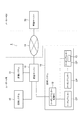
図1は、本実施形態に係る制御システム1の構成を模式的に示す図である。
図1に示すように、制御システム1は、店舗システム10を備えている。
店舗システム10は、スーパーマーケットや、コンビニエンスストア等の店舗に適用されるシステムであり、少なくとも、店舗に来店した顧客に対してクーポンを発行する機能を備えている。
店舗システム10は、クーポン発行用のクーポンプリンターCPを複数備えており、これらクーポンプリンターCP(記録装置)のそれぞれには、これらプリンターを制御するクーポンプリンター制御PC12が接続されている。クーポンプリンターCPは、記録媒体上を主走査方向に操作しつつ、インクカートリッジ13から供給されたインクを吐出可能な記録ヘッドたるインクジェットヘッド11(図2)を備え、このインクジェットヘッド11から記録媒体に対してインクを吐出して、記録媒体にカラーの画像を記録するインクジェットプリンターである。
インクジェットヘッド11にインクを供給するインクカートリッジ13には、ICチップ70が設けられており、このICチップ70には、記憶部たる不揮発性メモリー74(図2)が実装されている。ICチップ70の詳細な構成、及び、ICチップ70の使用の態様については、後述する。
店舗において、クーポンプリンターCPは、店舗に設けられた複数のレジカウンターごとに設置されており、後述するクーポンプリンター制御PC12の制御の下、所定のタイミングで、所定のクーポンを発行する。
Hereinafter, embodiments of the present invention will be described with reference to the drawings.
FIG. 1 is a diagram schematically illustrating a configuration of a
As shown in FIG. 1, the
The
The
The
In the store, the coupon printer CP is installed for each of a plurality of cashier counters provided in the store, and issues a predetermined coupon at a predetermined timing under the control of a coupon
図1に示すように、制御システム1では、複数の店舗システム10が、統括サーバー18に接続されている。具体的には、各店舗システム10が備えるクーポンプリンター制御PC12は、統括サーバー18と、通信可能に接続されている。
統括サーバー18は、各店舗システム10に設けられたクーポンプリンター制御PC12を統括的に制御する。
統括サーバー18、及び、店舗システム10は、店舗を運営する主体によって管理されるものである。この店舗を運営する主体は、自身が運営する店舗のそれぞれに、店舗システム10を構築すると共に、本社ビル等に、統括サーバー18を設置し、この統括サーバー18により、各店舗システム10を管理する。以下の説明では、店舗を運営する主体のことを便宜的にユーザーUと称するものとする。
As shown in FIG. 1, in the
The
The
統括サーバー18は、インターネット等のネットワーク19を介して、管理サーバー20(制御装置)に接続されている。これら統括サーバー18と、管理サーバー20とは、所定の暗号化プロトコルに準じた通信や、仮想専用線を介した通信、物理的な専用線を介した通信により、セキュアな通信を行う。
管理サーバー20は、インクカートリッジ13を製造し、販売する主体であるメーカーMが管理するサーバー装置である。
本実施形態では、メーカーMは、店舗において、使用済となったインクカートリッジ13を回収するサービスを行っている。
使用済のインクカートリッジ13の回収は、例えば、ユーザーUが、メーカーMに使用済のインクカートリッジ13を郵送したり、メーカーMにおける担当者が定期的に、又は、ユーザーUの要望に応じて、店舗を直接訪問してインクカートリッジ13を回収したり、また、所定のシステムインテグレーターを介して回収したりする等して、行われる。
回収された使用済のインクカートリッジ13は、環境負担を低減した方法で処分されたり、また、インクが充填されて再利用されたりする等して、資源の有効活用、環境負担の低減が図られる。
The
The
In the present embodiment, the manufacturer M performs a service for collecting the used
The collection of the used
The collected used
図2は、クーポンプリンターCP、及び、クーポンプリンターCPを制御するクーポンプリンター制御PC12の機能的構成を示すブロック図である。
FIG. 2 is a block diagram showing a functional configuration of the coupon printer CP and the coupon
クーポンプリンターCPは、インクジェットプリンターであるが、少なくとも、クリーニング動作、及び、フラッシング動作を実行可能である。
クリーニング動作とは、インクジェットヘッド11(図2)のノズル(不図示)内部に留まっているインクについて、時間の経過と共にインクの粘度が増加し、これに起因して吐出不良が起きることを防止するために、ノズルに留まっているインクを強制的に吸引する動作である。
クーポンプリンターCPは、インクジェットヘッド11のノズルに負圧を加え、ノズルに留まっているインクを吸い出す機構を備えており、当該機構によりフラッシング動作が実行される。
このクリーニング動作は、プリンター側制御部23により自動で実行されるほか、ユーザーU(例えば、店舗の担当者)の明示の指示をトリガーとして実行される。このように、指示によってクリーニング動作が行われる場合は、吐出不良や、吐出不良を想起させるような何らかの事象が発生しており、これらを解消するために、クリーニング動作が実行されたものと想定される。
The coupon printer CP is an inkjet printer, but can execute at least a cleaning operation and a flushing operation.
The cleaning operation is to prevent the ink remaining in the nozzle (not shown) of the ink jet head 11 (FIG. 2) from increasing in viscosity with time and causing an ejection failure due to this. Therefore, it is an operation for forcibly sucking the ink remaining in the nozzle.
The coupon printer CP includes a mechanism that applies a negative pressure to the nozzles of the
This cleaning operation is automatically executed by the printer-
フラッシング動作とは、記録媒体にインクが吐出されない状態で、ノズルからインクを吐出し、ノズルに留まっているインクを新たなインクに置き換える動作である。
インクジェットヘッド11が備える多数のノズルでは、時間の経過と共に、ノズルに留まっているインクが乾燥等により増粘して、これが吐出不良の要因となることがある。
フラッシング動作は、この吐出不良を防止するために実行される動作であり、インクジェットヘッド11が備えるノズルから所定量のインクが吐出され、各ノズルに留まっているインクが新たなインクに置き換えられる。
フラッシング動作は、記録動作の実行中、所定時間が経過する毎に、また、所定の条件が成立したタイミングで、自動で、インクジェットヘッド11がホームポジションHPに移動されて実行される。
The flushing operation is an operation in which ink is ejected from the nozzle in a state where ink is not ejected to the recording medium, and the ink remaining at the nozzle is replaced with new ink.
In a large number of nozzles provided in the
The flushing operation is an operation performed to prevent this ejection failure, and a predetermined amount of ink is ejected from the nozzles provided in the
The flushing operation is performed by automatically moving the
図2に示すように、クーポンプリンターCPは、プリンター側制御部23と、プリントエンジン24と、プリンター側表示部25と、プリンター側入力部29と、プリンター側インターフェイス26と、プリンター側記憶部27と、プリンター側通信制御部30とを備えている。
プリンター側制御部23は、クーポンプリンターCPの各部を中枢的に制御するものであり、演算実行部としてのCPUや、このCPUに実行されるファームウェアをコンピューターに読み取り可能な態様で不揮発的に記憶するROM、CPUに実行されるプログラムやこのプログラムに係るデータ等を一時的に記憶するRAM、その他の周辺回路等を備えている。このプリンター側制御部23は、インク消費量検出部31と、エラー情報生成部32と、情報書込部33と、を備えているが、これらについては、後述する。
プリントエンジン24は、プリンター側制御部23の制御の下、各種センサーの検出値を監視しながら、上述したインクジェットヘッド11のほか、記録媒体を搬送する搬送ローラーを駆動するための搬送モーターや、インクジェットヘッド11を主走査方向に走査させるためのキャリッジを駆動するキャリッジ駆動モーター等を動作させて、記録媒体に画像を記録することにより、クーポンを発行する。
プリンター側表示部25は、液晶表示パネル等の表示パネルを備え、プリンター側制御部23の制御の下、表示パネルに各種情報を表示する。プリンター側入力部29は、クーポンプリンターCPに設けられた各種操作スイッチに接続され、操作スイッチに対する操作を検出し、プリンター側制御部23に出力する。
プリンター側インターフェイス26は、プリンター側制御部23の制御の下、クーポンプリンター制御PC12との間で、所定の規格に準拠した通信を行う。
プリンター側記憶部27は、EEPROMや、ハードディスク等を備え、各種データを書き換え可能に記憶する。
As shown in FIG. 2, the coupon printer CP includes a printer-
The printer-
The
The printer-
The
The printer-
インクカートリッジ13は、装着部28に装着される。装着部28には、インクをインクジェットヘッド11に供給する流路口が形成されている。
プリンター側通信制御部30は、インクカートリッジ13のICチップ70のチップ側通信制御部71との間で、所定の規格に準拠した近距離無線通信を行う。
データの送信時、プリンター側通信制御部30は、送信データのエンコードを行って変調/復調部に出力し、この変調/復調部は、エンコードされた送信データを変調してRF部に出力し、このRF部は、変調された送信データを電波としてアンテナを介してチップ側通信制御部71に出力する。一方、データの受信時、RF部は、アンテナを介してチップ側通信制御部71から受信した電波を示す信号を変調/復調部に出力し、この変調/復調部は、RF部から入力された信号に基づいて、受信データをデコードし、プリンター側制御部23に出力する。
The
The printer-side
At the time of data transmission, the printer-side
上述したように、インクジェットヘッド11には、インクカートリッジ13からインクが供給される。
図2に示すように、インクカートリッジ13には、ICチップ70が設けられており、このICチップ70は、チップ側通信制御部71と、チップ側制御部72と、メモリーインターフェイス部73と、不揮発性メモリー74(記憶部)と、を備えている。
チップ側制御部72は、ICチップ70の各部を中枢的に制御する。
チップ側通信制御部71は、チップ側制御部72の制御の下、上述したプリンター側通信制御部30と同様の方法により、プリンター側通信制御部30との間で、所定の規格に準拠した近距離無線通信を行う。
不揮発性メモリー74は、ICチップ70に実装された記憶素子を備え、各種データを書き換え可能、かつ、不揮発的に記憶する。
チップ側制御部72は、メモリーインターフェイス部73を介して、不揮発性メモリー74にアクセスして、不揮発性メモリー74にデータを書き込み、また、不揮発性メモリー74からデータを読み出すことが可能である。
なお、ICチップ70の各部への電力は、プリンター側通信制御部30から受信した電力供給用の搬送波を利用して、行われる。この他、インクカートリッジ13に電池を設け、この電池から電力を供給する構成であってもよい。
また、本実施形態では、プリンター側制御部23と、チップ側制御部72とは、無線通信を行うが、有線通信を行う構成であってもよい。
また、ICチップ70は、不揮発性メモリー74を基板に搭載し、基板から不揮発性メモリー74信号線用の電極を露出させる構成とする。プリンター側通信制御部30には、不揮発性メモリー74側の電極と接触させる電極ピンが配置され、この電極ピンを介して不揮発性メモリー74にアクセスしてデータを読み出すようにしてもよい。
As described above, ink is supplied from the
As shown in FIG. 2, the
The chip-
The chip-side
The
The chip-
Note that power to each unit of the
In the present embodiment, the printer-
Further, the
次いで、プリンター側制御部23が備えるインク消費量検出部31について説明する。
インク消費量検出部31は、インクカートリッジ13がクーポンプリンターCPに搭載された後に、インクカートリッジ13のインクが吐出された回数(ショット数)である累計ショット数を計数する。
具体的には、プリンター側記憶部27には、インクカートリッジ13がクーポンプリンターCPに搭載された後、現時点に至るまでの、当該インクカートリッジ13からインクが吐出された回数の累計(累計ショット数)を示す第1累計ショット数データ41が記憶されており、インク消費量検出部31は、1のインクカートリッジ13のインクについて、1つのノズル孔から、1回、インクが吐出される度に、当該1のインクカートリッジ13に係る第1累計ショット数データ41が示す値をインクリメントすることにより、累計ショット数を計数する。例えば、記録媒体に画像を記録する際に、1のインクカートリッジ13のインクが100回吐出された場合、当該1のインクカートリッジ13に係る第1累計ショット数データ41が示す値は、画像の記録前の値に「100」加算された値となる。
Next, the ink
The ink consumption
Specifically, in the printer-
ここで、本実施形態では、インク消費量検出部31による累計ショット数の計数に際し、上述したクリーニング動作や、フラッシング動作でインクが吐出されたときのショット数は、計数されない。これは、後述するように、制御システム1では、計数された累計ショット数に基づいて、課金が行われることとなるが、クリーニング動作、及び、フラッシング動作によって消費されるインクは、記録媒体への画像の記録に使用されたものではなく、従って、ユーザーUの意図の下、使用されたものではなく、従って、これら動作において使用されたインクの量に対応する分は、課金の対象とすべきではなく、従って、累計ショット数に含めるべきではないからである。
Here, in the present embodiment, when the cumulative number of shots is counted by the ink consumption
次いで、プリンター側制御部23が備えるエラー情報生成部32について説明する。
エラー情報生成部32は、プリンター側記憶部27に記憶された第1エラーログファイル42を生成し、適宜、その内容を変更する。
第1エラーログファイル42は、クーポンプリンターCPに発生したエラーを、時系列でテキストデータとして記述したファイルであり、具体的には、エラーが発生した日時(日付、時刻)と、発生したエラーの名称と、エラーの内容と、が対応づけて記述されたファイルである。
エラーには、例えば、インクジェットヘッド11、キャリッジ、各種センサー、各種モーター、その他の装置、機構に関して発生するエラー、インクジェットヘッド11の吐出不良や、搬送不良等、記録動作に係るエラー、メモリーのオーバーフローや、変数の値の異常等、ソフトウェア的な処理の実行中に発生するエラー等がある。
エラー情報生成部32は、クーポンプリンターCPに電源が投入されている間、エラーが発生したか否かを監視し、エラーが発生したことを検出した場合、当該エラーにいて、発生日時、エラーの名称、エラーの内容をそれぞれ、第1エラーログファイル42に記述する。
エラー情報生成部32は、インクカートリッジ13ごとに、第1エラーログファイル42を生成する。詳述すると、1のインクカートリッジ13が取り付けられると、エラー情報生成部32は、当該1のインクカートリッジ13に係る第1エラーログファイル42を生成する。そして、エラー情報生成部32は、当該1のインクカートリッジ13が交換のために取り外されるまでの間、エラーに応じて、エラーに係る情報を第1エラーログファイル42に記述する。
Next, the error
The error
The first
The errors include, for example, errors that occur with respect to the
The error
The error
次いで、情報書込部33について説明する。
情報書込部33は、プリンター側通信制御部30を制御して、チップ側制御部72に、不揮発性メモリー74の第2累計ショット数データ80、及び、第2エラーログファイル81の内容を書き換えさせる。
第2累計ショット数データ80とは、上述した累計ショット数を示すデータであり、第2エラーログファイル81とは、エラーログを示すデータである。
情報書込部33は、インク消費量検出部31により、プリンター側記憶部27の第1累計ショット数データ41が書き換えられたタイミングで、適宜、ICチップ70の不揮発性メモリー74に記憶された第2累計ショット数データ80を書き換える。
また、情報書込部33は、エラー情報生成部32により、プリンター側記憶部27の第1エラーログファイル42に情報が記述されたタイミングで、適宜、ICチップ70の不揮発性メモリー74に記憶された第2エラーログファイル81を書き換える。
この他、情報書込部33は、インクカートリッジ13がクーポンプリンターCPから取り外される動作が開始されたことを検出した場合に、プリンター側記憶部27の第1累計ショット数データ41、及び、第1エラーログファイル42に基づいて、ICチップ70の不揮発性メモリー74に記憶された第2累計ショット数データ80、及び、第2エラーログファイル81を書き換えるようにしてもよい。
すなわち、クーポンプリンターCPからインクカートリッジ13が取り外され、使用済のインクカートリッジ13となった場合は、当該使用済のインクカートリッジ13の不揮発性メモリー74に記憶された第2累計ショット数データ80の値が、インクカートリッジ13がクーポンプリンターCPに装着されてから、取り外されるまでの累計ショット数を示す値となっており、かつ、第2エラーログファイル81の内容が、インクカートリッジ13がクーポンプリンターCPに装着されてから、取り外されるまでのエラーに関するエラーログとなっていれば、情報書込部33によるデータの書き換えのタイミングは、いつでもよい。この場合、インクカートリッジ13がクーポンプリンターCPから取り外された段階では、第1累計ショット数データ41と、第2累計ショット数データ80とが同一性を有し、かつ、第1エラーログファイル42と第2エラーログファイル81とが同一性を有した状態となっている。
なお、プリンター側制御部23にはRTCが接続されており、プリンター側制御部23は、このRTCからの入力値に基づいて、現在の日時を検出可能である。
Next, the
The
The second cumulative
The
The
In addition, when the
That is, when the
Note that an RTC is connected to the printer-
また、図2に示すように、クーポンプリンター制御PC12は、クーポンプリンター制御PC12の各部を中枢的に制御するホスト側制御部36と、表示パネルに各種情報を表示するホスト側表示部37と、各種入力デバイスに対する操作を検出し、ホスト側制御部36に出力するホスト側入力部38と、各種データを書き換え可能に記憶するホスト側記憶部39と、クーポンプリンターCP、及び、統括サーバー18と通信するホスト側通信インターフェイス40と、を備えている。
クーポンプリンター制御PC12には、クーポンプリンターCP制御用のプリンタードライバーがインストールされており、クーポンの発行に際し、ホスト側制御部36は、プリンタードライバーを読み出して実行することにより、クーポンの発行に係る各種動作を実行させるための制御コマンドを生成し、クーポンプリンターCPに出力する。
クーポンプリンターCPのプリンター側制御部23は、入力された制御コマンドに基づいて、プリントエンジンを制御して、クーポンの発行に係る各種動作を実行する。
ホスト側制御部36が備えるデータ仲介部85については、後述する。
As shown in FIG. 2, the coupon
The coupon
The printer-
The
図3は、統括サーバー18の機能的構成を示すブロック図である。
図3に示すように、統括サーバー18は、統括サーバー18の各部を中枢的に制御する統括サーバー側制御部43と、表示パネルに各種情報を表示する統括サーバー側表示部44と、各種入力デバイスに対する操作を検出し、統括サーバー側制御部43に出力する統括サーバー側入力部45と、各種データを書き換え可能に記憶する統括サーバー側記憶部46と、クーポンプリンター制御PC12と通信する統括サーバー側通信インターフェイス47と、を備えている。
統括サーバー側制御部43が備えるデータ送信部48については、後述する。
FIG. 3 is a block diagram showing a functional configuration of the
As shown in FIG. 3, the
The
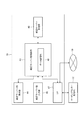
図4は、管理サーバー20の機能的構成を模式的に示すブロック図である。
図4に示すように、管理サーバー20は、管理サーバー20の各部を中枢的に制御する管理サーバー側制御部56と、表示パネルに各種情報を表示する管理サーバー側表示部57と、各種入力デバイスに対する操作を検出し、管理サーバー側制御部56に出力する管理サーバー側入力部58と、各種データを書き換え可能に記憶する管理サーバー側記憶部59と、ネットワーク19を介して、統括サーバー18と通信する管理サーバー側通信インターフェイス60と、を備えている。
管理サーバー側通信制御部61は、管理サーバー側制御部56の制御の下、インクカートリッジ13のチップ側通信制御部71と通信する。通信方法は、上述したプリンター側通信制御部30と同様である。
また、管理サーバー側通信制御部61の代わりに、クーポンプリンターCPを接続して使用してもよい。回収して戻ってきたインクカートリッジ13をクーポンプリンターCPに装着し、プリンター側通信制御部30からデータを取得し、管理サーバー側通信インターフェイス60を介して取得することができる。 管理サーバー側制御部56は、情報取得部62と、情報読取部63と、情報照合部64と、警告部65を、を備えているが、これらについては、後述する。
FIG. 4 is a block diagram schematically showing a functional configuration of the
As shown in FIG. 4, the
The management server side
Further, instead of the management server side
次いで、管理サーバー側制御部56が備える情報取得部62について、クーポンプリンター制御PC12のデータ仲介部85、及び、統括サーバー18のデータ送信部48と併せて説明する。これら情報取得部62,データ仲介部85、及び、データ送信部48の機能は、CPUがプログラムを実行する等、ハードウェアとソフトウェアとの協働により実現される。
情報取得部62は、クーポンプリンターCPから1のインクカートリッジ13が取り外される場合に、当該クーポンプリンターCPから、当該1のインクカートリッジ13に係る第1累計ショット数データ41、及び、第1エラーログファイル42を取得する。
具体的には、プリンター側制御部23は、インクカートリッジ13の交換が行われようとしていることを検出すると、その旨、ホスト側制御部36のデータ仲介部85に通知する。なお、インクカートリッジ13の交換が行われる場合は、ユーザーが、クーポンプリンターCPに設けられた操作スイッチを操作して、その旨入力を行う構成となっており、プリンター側制御部23は、当該入力を受け付けた場合に、インクカートリッジ13の交換が行われようとしていると判別する。
次いで、データ仲介部85は、プリンター側制御部23を制御して、プリンター側記憶部27に記憶された第1累計ショット数データ41、及び、第1エラーログファイル42を自身に送信させる。プリンター側制御部23から第1累計ショット数データ41、及び、第1エラーログファイル42を受信すると、データ仲介部85は、受信したこれらデータを、統括サーバー18の統括サーバー側制御部43のデータ送信部48に送信する。
データ仲介部85から第1累計ショット数データ41、及び、第1エラーログファイル42を受信したデータ送信部48は、さらに、これらデータを、ネットワーク19を介して、管理サーバー20の情報取得部62に送信する。
情報取得部62は、データ送信部48から第1累計ショット数データ41、及び、第1エラーログファイル42を受信することにより、これらデータを取得する。
さらに、情報取得部62は、受信した第1累計ショット数データ41、及び、第1エラーログファイル42を、管理サーバー側記憶部59に記憶する。
Next, the
When one
Specifically, when the printer-
Next, the
The
The
Further, the
次いで、情報読取部63、情報照合部64、及び、警告部65の説明と併せて、管理サーバー20の動作について説明する。
これら情報読取部63、情報照合部64、及び、警告部65の機能は、CPUがプログラムを実行する等、ハードウェアとソフトウェアとの協働により実現される。
Next, the operation of the
The functions of the
図5は、管理サーバー20の動作を示すフローチャートである。
以下の説明では、あるインクカートリッジ13について、クーポンプリンターCPで使用された後、交換のため当該クーポンプリンターCPから取り外され、さらに、メーカーMによって回収された後、管理サーバー側通信制御部61と、チップ側通信制御部71との間で、無線通信が可能な所定の位置にセットされているものとする。本実施形態に係る制御システム1では、使用済のインクカートリッジ13ごとに、以下に説明する処理が行われる。
また、以下の説明において、第1累計ショット数データ41、及び、第1エラーログファイル42は、回収され、上記所定の位置にセットされたインクカートリッジ13に係るデータである。つまり、上記所定の位置にセットされたインクカートリッジ13が、クーポンプリンターCPから取り外された際に、情報取得部62により取得され、管理サーバー側記憶部59に記憶されたデータである。
FIG. 5 is a flowchart showing the operation of the
In the following description, after a
In the following description, the first cumulative
図5に示すように、まず、管理サーバー20の管理サーバー側制御部56の情報読取部63は、管理サーバー側通信制御部61を制御して、インクカートリッジ13の不揮発性メモリー74に記憶された第2累計ショット数データ80、及び、第2エラーログファイル81を読み取る(ステップSA1)。
次いで、管理サーバー側制御部56の情報照合部64は、管理サーバー側記憶部59に記憶された第1累計ショット数データ41と、ステップSA1で読み取った第2累計ショット数データ80とを照合する(ステップSA2)。なお、ステップSA2では、データの形式や、データ型の相違は考慮されず、第1累計ショット数データ41が示す値と、第2累計ショット数データ80が示す値との比較が行われる。つまり、ステップSA2では、データの内容の同一性があるか否かの判別が行われる。
As shown in FIG. 5, first, the
Next, the
ここで、第1累計ショット数データ41が示す値と、第2累計ショット数データ80が示す値とが異なっている場合について考える。
上述したように、第1累計ショット数データ41、及び、第2累計ショット数データ80は、それぞれ、インクカートリッジ13がクーポンプリンターCPに取り付けられている間における累計ショット数を示すデータであるため、これらデータが示す値は、一致するはずである。そして、以下のような場合に、これらデータが示す値が不一致となるものと想定される。
まず、第1累計ショット数データ41が、クーポンプリンター制御PC12、統括サーバー18、及び、ネットワーク19を経由して、管理サーバー20に入力される際に、いずれかの段階で、第3者が、当該データを改ざんする場合がある。
また、使用済のインクカートリッジ13がメーカーMによって回収される過程で、第3者が、インクカートリッジ13のICチップ70の不揮発性メモリー74にアクセスし、データを改ざんする場合がある。
また、各記憶領域へのデータの書き込みに係るプログラムにおけるバグや、一時的な書き込みエラー、累計ショット数を管理する処理のエラー、その他の恒常的、一時的なソフトウェア的、ハードウェア的なエラーに起因して、第1累計ショット数データ41、及び/又は、第2累計ショット数データ80が正常に更新されなかった場合がある。
このように、第1累計ショット数データ41が示す値と、第2累計ショット数データ80が示す値とが異なっている場合は、改変やエラー等に起因して、いずれかの値が正しい値ではないと考えられる。
Here, consider a case where the value indicated by the first cumulative
As described above, the first cumulative
First, when the first cumulative
Further, in the process in which the used
In addition, bugs in programs related to data writing to each storage area, temporary write errors, errors in processing to manage the cumulative number of shots, and other permanent, temporary software and hardware errors As a result, the first cumulative
As described above, when the value indicated by the first cumulative
以上を踏まえ、情報照合部64により、第1累計ショット数データ41と第2累計ショット数データ80と内容が照合された結果、これらデータの内容が不一致(同一性を有さない)の場合(ステップSA3:NO)、管理サーバー側制御部56の警告部65は、管理サーバー側表示部57を制御して、表示パネルにその旨表示する(ステップSA4)。
これにより、ユーザーUは、第1累計ショット数データ41、及び、第2累計ショット数データ80のいずれかが、正しい値ではないことを迅速に認識でき、不一致が発生した原因究明や、その不一致の解消を開始することができる。
一方、第1累計ショット数データ41と第2累計ショット数データ80とが一致(同一性を有する)する場合(ステップSA3:YES)、管理サーバー側制御部56は、課金処理を実行する(ステップSA5)。
この課金処理では、第1累計ショット数データ41、及び、第2累計ショット数データ80が示す累計ショット数に基づいて、請求金額が算出され、例えば、請求書の発行等が行われる。
Based on the above, when the contents of the first cumulative
As a result, the user U can quickly recognize that either the first cumulative
On the other hand, when the first cumulative
In this billing process, a billing amount is calculated based on the cumulative number of shots indicated by the first cumulative
このように、本実施形態では、第1累計ショット数データ41、及び、第2累計ショット数データ80が一致する場合にのみ、これらデータが示す累計ショット数に基づいて課金が行われる。これにより、少なくとも、第1累計ショット数データ41、及び、第2累計ショット数データ80の不一致を発生させるような何らかの事象が発生しており、これらデータが示す累計ショット数の値の信頼性が低い場合に、当該累計ショット数に基づいて課金を行うことを確実に防止できる。特に、累計ショット数が正しくない場合、ユーザーUに請求する金額も正しくないものとなり、ユーザーUに不当な不利益を与える場合もあるが、このような事態が発生することを効果的に防止できる。
Thus, in the present embodiment, only when the first cumulative
さて、前掲図5に戻り、ステップSA4、又は、ステップSA5を実行した後、情報照合部64は、管理サーバー側記憶部59に記憶された第1エラーログファイル42と、ステップSA1で読み取った第2エラーログファイル81とを照合する(ステップSA6)。ステップSA6では、データの形式や、データ型の相違、ログにおけるデータの配置は考慮されず、第1エラーログファイル42の内容と、第2エラーログファイル81の内容との比較が行われ、これらファイルの内容に同一性があるか否かの判別が行われる。
Now, referring back to FIG. 5, after executing step SA4 or step SA5, the
情報照合部64による照合の結果、第1エラーログファイル42と、第2エラーログファイル81との内容が一致しない場合(ステップSA7:NO)、警告部65は、表示パネルにその旨表示し、警告する(ステップSA8)。これにより、第1エラーログファイル42と、第2エラーログファイル81とが一致していないことをユーザーUは、迅速に認識できる。
一方、第1エラーログファイル42と、第2エラーログファイル81との内容が一致する場合(ステップSA7:YES)、管理サーバー側制御部56は、これらいずれかのログの内容に基づいて、管理サーバー側記憶部59に記憶されたエラー情報DB86を更新する。
If the contents of the first
On the other hand, when the contents of the first
エラー情報DB86とは、クーポンプリンターCPを含む、メーカーMが提供したプリンターについて、機種毎に、発生したエラーを管理するデータベースである。
例えば、エラー情報DB86では、プリンターの機種毎に、発生したエラーの傾向や、所定のエラーの頻度、1のエラーと他のエラーとの関係を示す情報、その他のエラーに関する情報が記憶されている。
このエラー情報DB86は、メーカーMが、販売している、所定の機種のプリンターのエラーの傾向を分析したり、発生しているエラーに対処したり、また、新たなプリンターを開発する際に、有益な情報として利用される。
管理サーバー20には、1のログファイルを入力として、当該1のログファイルの内容がエラー情報DB86に適切に反映されるように、エラー情報DB86を更新する処理に係るアルゴリズムが組み込まれたプログラムが記憶されており、管理サーバー20は、当該プログラムを実行することにより、エラー情報DB86を更新する。
The
For example, the
This
The
ここで、エラー情報DB86は、上述したように、所定の機種のプリンターのエラーの傾向を分析したり、発生しているエラーに対処したり、また、新たなプリンターを開発する際に、有益な情報として利用されるものである。従って、エラー情報DB86を更新する際の元データとなる第1エラーログファイル42、及び、第2エラーログファイル81には、一定の正確性が求められる。
そして、本実施形態では、第1エラーログファイル42、及び、第2エラーログファイル81の内容が一致する場合にのみ、これらファイルの内容に基づいてエラー情報DB86の更新が行われる。これにより、少なくとも、第1エラーログファイル42、及び、第2エラーログファイル81の不一致を発生させるような何らかの事象が発生しており、これらファイルの内容の信頼性が低い場合に、エラー情報DB86の更新が行われることを確実に防止できる。
Here, as described above, the
In this embodiment, the
以上説明したように、本実施形態に係る管理サーバー20は、インクカートリッジ13の不揮発性メモリー74に記憶された第2累計ショット数データ80、及び、第2累計ショット数データ80(関連情報)を読み取る情報読取部63と、クーポンプリンターCPから、通信により、第1累計ショット数データ41、及び、第1エラーログファイル42(関連情報)を取得する情報取得部62と、情報読取部63により読み取られた各データと、情報取得部62により取得された各データとを照合する情報照合部64と、を備えている。
これによれば、比較対象となるいずれかのデータが正しくない状態となっている場合、照合の結果不一致が発生することを利用して、情報照合部64による照合の結果に基づいて、取得したデータに、正しい情報ではない可能性があることを検出可能である。
As described above, the
According to this, when any data to be compared is in an incorrect state, it is obtained based on the result of the collation by the
また、本実施形態では、情報照合部64は、第1累計ショット数データ41(インク消費量を示す情報)と、第2累計ショット数データ80(インク消費量を示す情報)とを照合する。そして、本実施形態では、第1累計ショット数データ41、及び、第2累計ショット数データ80が一致する場合にのみ、これらデータが示す累計ショット数に基づいて課金が行われる。
これにより、少なくとも、第1累計ショット数データ41、及び、第2累計ショット数データ80の不一致を発生させるような何らかの事象が発生しており、これらデータが示す累計ショット数の値の信頼性が低い場合に、当該累計ショット数に基づいて課金を行うことを確実に防止できる。特に、累計ショット数が正しくない場合、ユーザーUに請求する金額も正しくないものとなり、ユーザーUに不当な不利益を与える場合もあるが、このような事態が発生することを効果的に防止できる。
In the present embodiment, the
As a result, at least some event that causes a mismatch between the first cumulative
また、本実施形態では、情報照合部64は、第1エラーログファイル42(発生したエラーに関するエラー情報)と、第2エラーログファイル81(発生したエラーに関するエラー情報)とのそれぞれの内容を照合する。そして、本実施形態では、第1エラーログファイル42、及び、第2エラーログファイル81の内容が一致する場合にのみ、これらファイルの内容に基づいてエラー情報DB86の更新が行われる。
これにより、少なくとも、第1エラーログファイル42、及び、第2エラーログファイル81の不一致を発生させるような何らかの事象が発生しており、これらファイルの内容の信頼性が低い場合に、エラー情報DB86の更新が行われることを確実に防止できる。
In the present embodiment, the
As a result, at least when an event that causes a mismatch between the first
また、本実施形態に係る管理サーバー20は、情報照合部64による照合の結果、データに同一性がないと判別された場合、その旨警告する警告部65をさらに備える。
これによれば、情報照合部64による照合の結果を迅速に把握可能となる。
Further, the
According to this, it becomes possible to quickly grasp the result of collation by the
なお、上述した実施の形態は、あくまでも本発明の一態様を示すものであり、本発明の範囲内で任意に変形および応用が可能である。
例えば、以下の機能をさらに備えるようにしてもよい。
すなわち、クーポンプリンターCPを、インクカートリッジ13のインク残量を検出する検出部、または、インクジェットヘッド11から吐出したインク量に基づきインクカートリッジ13のインク残量を算出する算出部を備える構成とする。
検出部は、例えば、インクカートリッジ13に充填されているインクのインク面の位置をフォトセンサーの透過、非透過により検出することにより、インク残量を検出する。また、算出部は、例えば、インクジェットヘッド11から記録のためにインクを吐出するショット数をカンウトし、カウントしたショット数をインク量に換算し、換算したインク量を、初期充填後のインク量から差し引きすることによりインク残量を算出する。この際、フラッシング等、記録のためではない用途で使用されたインクも考慮して、インク残量を算出する。
そして、クーポンプリンターCPの情報書込部33は、上述した検出部、又は、算出部によりインク残量が所定値以下となったことを検知すると、インクエンドとなった旨のインクエンド情報を、インクカートリッジ13の不揮発性メモリー74に書き込む。管理サーバー20は、情報読取部63の読み取り結果に基づいて、インクカートリッジ13の不揮発性メモリー74が書き込まれているか否か判別し、インクエンド情報が書き込まれている場合は、インクカートリッジ13がインクエンドであることを利用した処理を実行する。
この構成では、インク残量が所定値以下となったインクカートリッジ13については、インクエンドとなったことを示すインクエンド情報がインクカートリッジ13の不揮発性メモリー74に書き込まれることとなる。このため、管理サーバー20は、インクカートリッジ13の不揮発性メモリー74にインクエンド情報が書き込まれているか否かにより、当該インクカートリッジ13がインクエンドであるのか否かを迅速、かつ、容易に、検出できると共に、インクエンドである場合は、インクカートリッジ13がインクエンドであることを利用した適切な処理を実行できる。
例えば、インクエンドとなったインクカートリッジ13のインク残量はほぼ一定値となるので、管理サーバー20は、この値を事前に記憶しておくことにより、個別にインク残量を算出したり、検出したりすることなく、簡単にインク残量を推定でき、また、管理サーバー20は、初期充填後のインク量から、推定されたインク残量を差し引きすることにより、インク使用量も推定できる。
この場合、個別にインク残量を検出したり、インク残量を算出したりする場合と比較して、非常に容易にインク残量を検出することが可能となる。通常、インクエンドとなったインクカートリッジは使用済みのものとして回収されてくるので、インクエンド情報を利用して、各インクカートリッジのインク残量や、インク使用量を推定(算出)することにより、画一的に処理ができ、処理効率が向上すると共に、インク残量や、インク使用量を算出するために要する時間を短縮化できる。
The above-described embodiment is merely an aspect of the present invention, and can be arbitrarily modified and applied within the scope of the present invention.
For example, the following functions may be further provided.
That is, the coupon printer CP is configured to include a detection unit that detects the remaining amount of ink in the
For example, the detection unit detects the ink remaining amount by detecting the position of the ink surface of the ink filled in the
When the
In this configuration, for the
For example, since the ink remaining amount of the
In this case, it is possible to detect the remaining amount of ink very easily as compared with the case where the remaining amount of ink is individually detected or the remaining amount of ink is calculated. Normally, ink cartridges that have become ink ends are collected as used ones, so by using the ink end information to estimate (calculate) the remaining ink amount and ink usage of each ink cartridge, Uniform processing can be performed, the processing efficiency can be improved, and the time required to calculate the remaining ink amount and ink usage can be shortened.
また例えば、上述した実施形態では、関連情報は、第1累計ショット数データ41、第1エラーログファイル42、第2累計ショット数データ80、及び、第2エラーログファイル81であったが、関連情報はこれらに限らない。すなわち、正しい情報ではないことを検出することが求められる情報であって、クーポンプリンターCPを含む記録装置から通信により取得でき、かつ、インクカートリッジ13の不揮発性メモリー74に書き込み可能な情報であればよい。
また、本実施形態では、発生したエラーに関するエラー情報として、ログ形式のデータである第1エラーログファイル42、及び、第2エラーログファイル81を例示した。しかしながら、エラー情報は、ログ形式のデータに限らず、例えば、発生したエラーの一覧を示す情報でもよく、また、エラーごとに、発生した回数を示す情報であってもよい。すなわち、エラー情報は、エラーに関する情報であればその形式を問わない。
For example, in the above-described embodiment, the related information is the first cumulative
Further, in the present embodiment, the first
1…制御システム、11…インクジェットヘッド(記録ヘッド)、12…クーポンプリンター制御PC、13…インクカートリッジ、20…管理サーバー(制御装置)、31…インク消費量検出部、32…エラー情報生成部、33…情報書込部、41…第1累計ショット数データ(関連情報)、42…第1エラーログファイル(関連情報)、56…管理サーバー側制御部(制御部)、62…情報取得部、63…情報読取部、64…情報照合部、65…警告部、70…ICチップ、74…不揮発性メモリー(記憶部)、80…第2累計ショット数データ(関連情報)、81…第2エラーログファイル(関連情報)、CP…クーポンプリンター(記録装置)。
DESCRIPTION OF
Claims (8)
前記記録装置は、
第1記憶部を有しインクを再充填可能なインクカートリッジを装着する装着部と、
前記インクカートリッジから供給されるインクを記録媒体に付着させることにより記録を行う記録ヘッドと、
前記記録に関連する情報である関連情報を前記インクカートリッジの前記第1記憶部に書き込む情報書込部と、
前記関連情報を記憶する第2記憶部を有し、
前記制御装置は、
回収された前記インクカートリッジの前記第1記憶部から第1関連情報を読み取る情報読取部と、
前記記録装置と通信可能なものであり、前記記録装置から前記第2記憶部に記憶された第2関連情報を取得する情報取得部と、
前記情報読取部により読み取られた前記第1関連情報と、前記情報取得部により取得された前記第2関連情報とを照合する情報照合部と、
前記情報照合部による照合の結果、前記第1関連情報と前記第2関連情報が一致すると判別された場合、前記第1関連情報または前記第2関連情報に基づき課金情報を生成する制御部と、
を有することを特徴とする制御システム。 A control system comprising a recording device and a control device,
The recording device comprises:
A mounting portion for mounting the refillable ink cartridge ink have a first storage unit,
A recording head that performs recording by attaching ink supplied from the ink cartridge to a recording medium;
An information writing unit for writing related information, which is information related to the recording, into the first storage unit of the ink cartridge;
A second storage unit for storing the related information ;
The controller is
From the first storage unit of recovered said ink cartridge and the information reading section for reading the first additional information,
An information acquisition unit capable of communicating with the recording device, and acquiring second related information stored in the second storage unit from the recording device;
An information collating unit that collates the first related information read by the information reading unit and the second related information acquired by the information acquiring unit;
Result of the collation by the information collating unit, when the second additional information with the first related information is determined to match, and a control unit for generating billing information based on the first related information or the second related information ,
A control system comprising:
前記記録装置の前記情報書込部は、前記関連情報として、前記インク消費量検出部が検出したインク消費量を含む情報を、前記インクカートリッジの前記第1記憶部に書き込み、
前記第2記憶部は前記インク消費量を含む情報を記憶し、
前記制御装置の前記情報読取部は、回収された前記インクカートリッジの前記第1記憶部に記憶された第1インク消費量を含む第1情報を読み取り、
前記制御装置の前記情報取得部は、前記記録装置から前記第2記憶部に記憶された第2インク消費量を含む第2情報を取得し、
前記制御装置の前記情報照合部は、前記情報読取部により読み取られた前記第1情報と、前記情報取得部により取得された前記第2情報とを照合することを特徴とする請求項1に記載の制御システム。 The recording apparatus further includes an ink consumption amount detection unit configured to detect an ink consumption amount including ink consumed and attached to the recording medium by the recording head.
The information writing unit of the recording apparatus writes, as the related information, information including the ink consumption detected by the ink consumption detection unit to the first storage unit of the ink cartridge,
The second storage unit stores information including the ink consumption,
The information reading unit of the control device reads first information including a first ink consumption amount stored in the first storage unit of the collected ink cartridge;
The information acquisition unit of the control device acquires second information including a second ink consumption amount stored in the second storage unit from the recording device;
The said information collation part of the said control apparatus collates the said 1st information read by the said information reading part, and the said 2nd information acquired by the said information acquisition part. Control system.
前記記録装置の前記情報書込部は、前記関連情報として、前記エラー情報生成部により生成された前記エラー情報を、前記インクカートリッジの前記第1記憶部に書き込み、
前記第2記憶部は前記エラー情報を記憶し、
前記制御装置の前記情報読取部は、回収された前記インクカートリッジの前記第1記憶部に記憶された第1エラー情報を読み取り、
前記制御装置の前記情報取得部は、前記記録装置から前記第2記憶部に記憶された第2エラー情報を取得し、
前記制御装置の前記情報照合部は、前記情報読取部により読み取られた前記第1エラー情報と、前記情報取得部により取得された前記第2エラー情報とを照合することを特徴とする請求項1に記載の制御システム。 The recording apparatus further includes an error information generation unit that generates error information regarding an error that has occurred,
The information writing unit of the recording apparatus writes the error information generated by the error information generation unit as the related information in the first storage unit of the ink cartridge,
The second storage unit stores the error information,
The information reading unit of the control device reads first error information stored in the first storage unit of the collected ink cartridge;
The information acquisition unit of the control device acquires second error information stored in the second storage unit from the recording device,
2. The information collating unit of the control device collates the first error information read by the information reading unit and the second error information acquired by the information acquiring unit. The control system described in.
前記記録装置の前記情報書込部は、前記検出部または前記算出部により前記インク残量が所定値以下となったことを検知すると、前記関連情報として、インクエンドとなった旨のインクエンド情報を、前記インクカートリッジの前記第1記憶部に書き込み、
前記第2記憶部は前記インクエンド情報を記憶し、
前記制御装置の前記情報読取部は、回収された前記インクカートリッジの前記第1記憶部に記憶された第1インクエンド情報を読み取り、
前記制御装置の前記情報取得部は、前記記録装置から前記第2記憶部に記憶された第2インクエンド情報を取得し、
前記制御装置の前記情報照合部は、前記情報読取部により読み取られた前記第1インクエンド情報と、前記情報取得部により取得された前記第2インクエンド情報とを照合することを特徴とする請求項1に記載の制御システム。 The recording apparatus includes a detection unit that detects the remaining amount of ink in the ink cartridge, or a calculation unit that calculates the remaining amount of ink in the ink cartridge based on the amount of ink ejected from the recording head.
When the information writing unit of the recording apparatus detects that the ink remaining amount is equal to or less than a predetermined value by the detection unit or the calculation unit, ink end information indicating that the ink end has been detected as the related information. In the first storage unit of the ink cartridge,
The second storage unit stores the ink end information,
The information reading unit of the control device reads first ink end information stored in the first storage unit of the collected ink cartridge,
The information acquisition unit of the control device acquires second ink end information stored in the second storage unit from the recording device,
The information collation unit of the control device collates the first ink end information read by the information reading unit and the second ink end information acquired by the information acquisition unit. Item 2. The control system according to Item 1.
前記インクカートリッジから供給されるインクを記録媒体に付着させることにより記録を行う記録ヘッドと、前記記録に関連する情報である関連情報を前記インクカートリッジの前記第1記憶部に書き込む情報書込部と、前記関連情報を記憶する第2記憶部を有する記録装置と接続可能な制御装置であって、
回収された前記インクカートリッジの前記第1記憶部から第1関連情報を読み取る情報読取部と、
前記記録装置と通信可能なものであり、前記記録装置から前記第2記憶部に記憶された第2関連情報を取得する情報取得部と、
前記情報読取部により読み取られた前記第1関連情報と、前記情報取得部により取得された前記第2関連情報とを照合する情報照合部と、
前記情報照合部による照合の結果、前記第1関連情報と前記第2関連情報が一致すると判別された場合、前記第1関連情報または前記第2関連情報に基づき課金情報を生成する制御部と、を備えることを特徴とする制御装置。 A mounting portion for mounting the refillable ink cartridge ink have a first storage unit,
A recording head that performs recording by attaching ink supplied from the ink cartridge to a recording medium; and an information writing unit that writes related information that is information related to the recording in the first storage unit of the ink cartridge; A control device connectable to a recording device having a second storage unit for storing the related information ,
From the first storage unit of recovered said ink cartridge and the information reading section for reading the first additional information,
An information acquisition unit capable of communicating with the recording device, and acquiring second related information stored in the second storage unit from the recording device;
An information collating unit that collates the first related information read by the information reading unit and the second related information acquired by the information acquiring unit;
Result of the collation by the information collating unit, when the second additional information with the first related information is determined to match, and a control unit for generating billing information based on the first related information or the second related information A control device comprising:
回収された前記インクカートリッジの前記第1記憶部から第1関連情報を読み取り、
前記記録装置から、前記第2記憶部に記憶された第2関連情報を取得し、
読み取った前記第1関連情報と、取得した前記第2関連情報とを照合し、
前記第1関連情報と前記第2関連情報が一致すると判別した場合、前記第1関連情報または前記第2関連情報に基づき課金情報を生成することを特徴とする制御装置の制御方法。 A recording head for recording by adhering a mounting portion for mounting the refillable ink cartridge ink have a first storage unit, the ink supplied from the ink cartridge to the recording medium, relating to the recording A control method of a control device connectable to an information writing unit that writes related information that is information in the first storage unit of the ink cartridge and a recording device that has a second storage unit that stores the related information ,
From the first storage unit of recovered said ink cartridge read the first related information,
Obtaining the second related information stored in the second storage unit from the recording device;
The read first related information and the acquired second related information are collated,
When it is determined that the first related information matches the second related information, billing information is generated based on the first related information or the second related information.
前記制御部を、
回収された前記インクカートリッジの前記第1記憶部から第1関連情報を読み取り、
前記記録装置から、前記第2記憶部に記憶された第2関連情報を取得し、
読み取った前記第1関連情報と、取得した前記第2関連情報とを照合し、
前記第1関連情報と前記第2関連情報が一致すると判別した場合、前記第1関連情報または前記第2関連情報に基づき課金情報を生成するように機能させることを特徴とするプログラム。 A recording head for recording by adhering a mounting portion for mounting the refillable ink cartridge ink have a first storage unit, the ink supplied from the ink cartridge to the recording medium, relating to the recording For controlling each part of a control device connectable to an information writing unit for writing related information as information in the first storage unit of the ink cartridge and a recording device having a second storage unit for storing the related information A program executed by the control unit,
The control unit
From the first storage unit of recovered said ink cartridge read the first related information,
Obtaining the second related information stored in the second storage unit from the recording device;
The read first related information and the acquired second related information are collated,
A program for causing charging information to be generated based on the first related information or the second related information when it is determined that the first related information and the second related information match .
Priority Applications (3)
| Application Number | Priority Date | Filing Date | Title |
|---|---|---|---|
| JP2011074399A JP5765009B2 (en) | 2011-03-30 | 2011-03-30 | CONTROL SYSTEM, CONTROL DEVICE, CONTROL DEVICE CONTROL METHOD, AND PROGRAM |
| US13/431,120 US8876235B2 (en) | 2011-03-30 | 2012-03-27 | Control system, control device, and method of controlling a control device |
| US14/496,220 US9073335B2 (en) | 2011-03-30 | 2014-09-25 | Control system, control device, and method of controlling a control device |
Applications Claiming Priority (1)
| Application Number | Priority Date | Filing Date | Title |
|---|---|---|---|
| JP2011074399A JP5765009B2 (en) | 2011-03-30 | 2011-03-30 | CONTROL SYSTEM, CONTROL DEVICE, CONTROL DEVICE CONTROL METHOD, AND PROGRAM |
Publications (3)
| Publication Number | Publication Date |
|---|---|
| JP2012206426A JP2012206426A (en) | 2012-10-25 |
| JP2012206426A5 JP2012206426A5 (en) | 2014-04-03 |
| JP5765009B2 true JP5765009B2 (en) | 2015-08-19 |
Family
ID=46926632
Family Applications (1)
| Application Number | Title | Priority Date | Filing Date |
|---|---|---|---|
| JP2011074399A Expired - Fee Related JP5765009B2 (en) | 2011-03-30 | 2011-03-30 | CONTROL SYSTEM, CONTROL DEVICE, CONTROL DEVICE CONTROL METHOD, AND PROGRAM |
Country Status (2)
| Country | Link |
|---|---|
| US (2) | US8876235B2 (en) |
| JP (1) | JP5765009B2 (en) |
Families Citing this family (5)
| Publication number | Priority date | Publication date | Assignee | Title |
|---|---|---|---|---|
| CN108583020B (en) * | 2014-01-31 | 2020-06-26 | 惠普发展公司,有限责任合伙企业 | Ink supply and method for preparing the same |
| US9498970B2 (en) * | 2015-02-12 | 2016-11-22 | Quadtech, Inc. | System and method for monitoring ink use in a printing system |
| JP7326999B2 (en) | 2019-08-29 | 2023-08-16 | セイコーエプソン株式会社 | Printing device and printing system |
| US11132155B2 (en) * | 2019-09-27 | 2021-09-28 | Brother Kogyo Kabushiki Kaisha | Image forming apparatus having main body, main memory and controller, and consumable cartridge having cartridge memory therefor |
| US11163630B2 (en) * | 2019-10-18 | 2021-11-02 | Dell Products L.P. | Using real-time analytics to manage application features |
Family Cites Families (16)
| Publication number | Priority date | Publication date | Assignee | Title |
|---|---|---|---|---|
| JP2002036582A (en) | 2000-07-19 | 2002-02-05 | Sony Corp | Charging apparatus and method, and computer readable program memory medium in which program having charging function is recorded |
| JP2002225307A (en) | 2000-11-28 | 2002-08-14 | Seiko Epson Corp | Judgement on conformity between ink cartridge and printer |
| JP2003154734A (en) | 2001-11-21 | 2003-05-27 | Seiko Epson Corp | Printer and print cartridge for use therein |
| JP2004240756A (en) * | 2003-02-06 | 2004-08-26 | Seiko Epson Corp | Charging managing device, program used for the same and charging managing method |
| JP2004240836A (en) * | 2003-02-07 | 2004-08-26 | Seiko Epson Corp | System, method and program for delivering cartridge to home |
| JP2004265214A (en) * | 2003-03-03 | 2004-09-24 | Seiko Epson Corp | Charging managing device and method and program used for the same |
| JP2004302178A (en) * | 2003-03-31 | 2004-10-28 | Seiko Epson Corp | Charging control system and device used therefor |
| JP2005067195A (en) * | 2003-08-06 | 2005-03-17 | Seiko Epson Corp | Image formation system, and device used for the same |
| JP2005193567A (en) * | 2004-01-08 | 2005-07-21 | Canon Inc | Cartridge for printer, recycling recovery system of cartridge, recycling judgment system and discount system of cartridge |
| JP4970781B2 (en) * | 2005-02-03 | 2012-07-11 | 株式会社リコー | Image forming apparatus and method of controlling image forming apparatus |
| JP4742847B2 (en) * | 2005-12-16 | 2011-08-10 | セイコーエプソン株式会社 | Printer, printer system, and accounting method |
| JP4742815B2 (en) * | 2005-10-31 | 2011-08-10 | セイコーエプソン株式会社 | Printer, printer system, and accounting method |
| EP1780024B1 (en) * | 2005-10-31 | 2009-12-02 | Seiko Epson Corporation | Printer and printing system |
| JP4872951B2 (en) | 2008-03-06 | 2012-02-08 | セイコーエプソン株式会社 | Portable terminal, portable terminal control method, and portable terminal control program |
| JP5471260B2 (en) * | 2008-11-14 | 2014-04-16 | セイコーエプソン株式会社 | Liquid container |
| JP5577615B2 (en) * | 2009-04-01 | 2014-08-27 | セイコーエプソン株式会社 | Liquid consumption system, liquid consumption apparatus, liquid supply unit, and method for managing the remaining amount of liquid stored in the liquid supply unit |
-
2011
- 2011-03-30 JP JP2011074399A patent/JP5765009B2/en not_active Expired - Fee Related
-
2012
- 2012-03-27 US US13/431,120 patent/US8876235B2/en not_active Expired - Fee Related
-
2014
- 2014-09-25 US US14/496,220 patent/US9073335B2/en not_active Expired - Fee Related
Also Published As
| Publication number | Publication date |
|---|---|
| US9073335B2 (en) | 2015-07-07 |
| US20120249626A1 (en) | 2012-10-04 |
| US20150009251A1 (en) | 2015-01-08 |
| US8876235B2 (en) | 2014-11-04 |
| JP2012206426A (en) | 2012-10-25 |
Similar Documents
| Publication | Publication Date | Title |
|---|---|---|
| US9498972B2 (en) | Printer and printing system | |
| JP5765009B2 (en) | CONTROL SYSTEM, CONTROL DEVICE, CONTROL DEVICE CONTROL METHOD, AND PROGRAM | |
| US9390439B2 (en) | Invoice amount calculation method, invoice amount calculation device, and printer invoicing system | |
| JP2007118490A (en) | Printer and printer system | |
| JP4742847B2 (en) | Printer, printer system, and accounting method | |
| JP2003516556A (en) | Prevent unauthorized use of retention cartridges | |
| JP5884285B2 (en) | Control device, control method of control device, information processing device | |
| JP3988591B2 (en) | Print monitoring device via network | |
| JP4613399B2 (en) | Cartridge management apparatus, cartridge management method, and computer-readable program storage medium storing a program having a cartridge management function | |
| JP5857475B2 (en) | Billing fee calculation method, billing fee calculation device, and printer billing system | |
| JP5909892B2 (en) | Billing fee calculation method, billing fee calculation device, and printer billing system | |
| JP5428985B2 (en) | Electronic device and method thereof | |
| JP5560223B2 (en) | Ink cartridge management system and method of controlling ink cartridge management system | |
| JP2006035483A (en) | Liquid cartridge, liquid droplet ejecting apparatus, liquid cartridge reader, liquid cartridge managing system and management method | |
| JP2008120012A (en) | Image formation device and its control method |
Legal Events
| Date | Code | Title | Description |
|---|---|---|---|
| A521 | Request for written amendment filed |
Free format text: JAPANESE INTERMEDIATE CODE: A523 Effective date: 20140214 |
|
| A621 | Written request for application examination |
Free format text: JAPANESE INTERMEDIATE CODE: A621 Effective date: 20140214 |
|
| A977 | Report on retrieval |
Free format text: JAPANESE INTERMEDIATE CODE: A971007 Effective date: 20141008 |
|
| A131 | Notification of reasons for refusal |
Free format text: JAPANESE INTERMEDIATE CODE: A131 Effective date: 20141111 |
|
| A521 | Request for written amendment filed |
Free format text: JAPANESE INTERMEDIATE CODE: A523 Effective date: 20141225 |
|
| RD04 | Notification of resignation of power of attorney |
Free format text: JAPANESE INTERMEDIATE CODE: A7424 Effective date: 20150106 |
|
| TRDD | Decision of grant or rejection written | ||
| A01 | Written decision to grant a patent or to grant a registration (utility model) |
Free format text: JAPANESE INTERMEDIATE CODE: A01 Effective date: 20150519 |
|
| A61 | First payment of annual fees (during grant procedure) |
Free format text: JAPANESE INTERMEDIATE CODE: A61 Effective date: 20150601 |
|
| R150 | Certificate of patent or registration of utility model |
Ref document number: 5765009 Country of ref document: JP Free format text: JAPANESE INTERMEDIATE CODE: R150 |
|
| S531 | Written request for registration of change of domicile |
Free format text: JAPANESE INTERMEDIATE CODE: R313531 |
|
| R350 | Written notification of registration of transfer |
Free format text: JAPANESE INTERMEDIATE CODE: R350 |
|
| LAPS | Cancellation because of no payment of annual fees |