以下に図面を参照し、本発明にかかる遊技機の好適な実施の形態を詳細に説明する。以下に説明する実施の形態では本発明にかかる遊技機を、旧第1種に属するぱちんこ遊技機(所謂「デジパチ」)に適用した場合の例を説明するが、本発明の内容を限定するものではない。また、以下の実施の形態で示す具体的な数値などは一例であって、本発明の内容を限定するものではない。
Hereinafter, preferred embodiments of a gaming machine according to the present invention will be described in detail with reference to the drawings. In the embodiment described below, an example in which the gaming machine according to the present invention is applied to a pachinko gaming machine (so-called “digital patch”) belonging to the former type 1 will be described, but the contents of the present invention are limited. is not. Further, specific numerical values and the like shown in the following embodiments are merely examples, and do not limit the contents of the present invention.
(遊技機の基本構成)
まず、本発明の実施の形態にかかる遊技機の基本構成について説明する。図1は、本発明の実施の形態にかかる遊技機の一例を示す説明図である。図1に示すように、本実施の形態の遊技機100は遊技盤101を備える。遊技盤101の下部位置には遊技球を発射する発射部(図7の符号728参照)が設けられる。
(Basic configuration of gaming machine)
First, the basic configuration of the gaming machine according to the embodiment of the present invention will be described. FIG. 1 is an explanatory diagram showing an example of a gaming machine according to an embodiment of the present invention. As shown in FIG. 1, the gaming machine 100 according to the present embodiment includes a gaming board 101. A launching unit (see reference numeral 728 in FIG. 7) for launching a game ball is provided at a lower position of the game board 101.
発射部により発射された遊技球は、レール102に沿って上昇して遊技盤101の上部位置に達した後、遊技領域103内を落下する。遊技領域103には遊技領域103内を落下する遊技球の落下軌道を変化させるための釘や風車などが設けられる。また、遊技領域103には遊技球が入賞可能な各種入賞口(例えば始動口および大入賞口)が設けられる。
The game ball launched by the launching unit rises along the rail 102 and reaches the upper position of the game board 101, and then falls in the game area 103. The game area 103 is provided with nails, windmills, and the like for changing the falling trajectory of the game ball falling in the game area 103. Further, the game area 103 is provided with various winning ports (for example, a starting port and a big winning port) through which game balls can be won.
遊技盤101には画像表示部104が設けられる。画像表示部104は、第1画像表示部104aと、第1画像表示部104aよりも表示領域の小さい第2画像表示部104bとを備える。第1画像表示部104aは遊技機100の所謂「メインディスプレイ」とされ、遊技盤101のほぼ中央部分に配置される。すなわち、第1画像表示部104aは遊技者にとって最も見易いと想定される位置に配置される。また、第2画像表示部104bは遊技機100の所謂「サブディスプレイ」とされ、図1に示すように第1画像表示部104aの上方に配置される。
The game board 101 is provided with an image display unit 104. The image display unit 104 includes a first image display unit 104a and a second image display unit 104b having a display area smaller than that of the first image display unit 104a. The first image display unit 104 a is a so-called “main display” of the gaming machine 100, and is arranged at a substantially central portion of the gaming board 101. That is, the first image display unit 104a is disposed at a position that is assumed to be most easily seen by the player. The second image display unit 104b is a so-called “sub-display” of the gaming machine 100, and is disposed above the first image display unit 104a as shown in FIG.
第1画像表示部104aおよび第2画像表示部104bには、液晶表示器(LCD:Liquid Crystal Display)などが用いられる。第1画像表示部104aおよび第2画像表示部104bは、遊技機100により表示制御され、各種画像(例えば後述の演出図柄や保留表示)を表示する。
For the first image display unit 104a and the second image display unit 104b, a liquid crystal display (LCD: Liquid Crystal Display) or the like is used. The first image display unit 104a and the second image display unit 104b are display-controlled by the gaming machine 100 and display various images (for example, later-described effect symbols and hold display).
画像表示部104の下方には遊技球が入賞可能な第1始動口105と第2始動口106とが設けられる。第2始動口106には開閉自在な普通電動役物107が設けられる。普通電動役物107が開放されているとき、遊技球は第2始動口106に入賞し易くなる。逆に、普通電動役物107が閉鎖されているとき、遊技球は第2始動口106に入賞し難くなる。普通電動役物107は通常時には閉鎖されており、普通図柄判定の判定結果に基づいて開放される。この普通図柄判定は、画像表示部104の左側および右側に配設されたゲート108を遊技球が通過することにより行われる。
Below the image display unit 104 are provided a first start port 105 and a second start port 106 through which game balls can be won. The second starting port 106 is provided with an ordinary electric accessory 107 that can be opened and closed. When the ordinary electric accessory 107 is opened, the game ball can easily win the second starting port 106. On the contrary, when the ordinary electric accessory 107 is closed, it is difficult for the game ball to win the second starting port 106. The normal electric accessory 107 is normally closed and is opened based on the determination result of the normal symbol determination. This normal symbol determination is performed when a game ball passes through the gates 108 provided on the left and right sides of the image display unit 104.
画像表示部104の右側には開閉自在な上大入賞口109aが設けられる。上大入賞口109aが開放されているとき、遊技球は上大入賞口109aに入賞可能となる。逆に、上大入賞口109aが閉鎖されているとき、遊技球は上大入賞口109aに入賞不可能となる。上大入賞口109aは通常時には閉鎖されており、大当たり判定の判定結果に基づいて開放される。この大当たり判定は、第1始動口105や第2始動口106に遊技球が入賞することにより行われる。
On the right side of the image display unit 104, an openable large winning opening 109a is provided. When the upper university winning opening 109a is opened, the game ball can be awarded to the upper university winning opening 109a. On the other hand, when the upper large winning opening 109a is closed, the game ball cannot be won in the upper large winning opening 109a. The top prize winning port 109a is normally closed and is opened based on the determination result of the jackpot determination. This jackpot determination is performed by winning a game ball at the first start port 105 or the second start port 106.
また、上大入賞口109aの下方には開閉自在な下大入賞口109bが設けられる。下大入賞口109bが開放されているとき、遊技球は下大入賞口109bに入賞可能となる。逆に、下大入賞口109bが閉鎖されているとき、遊技球は下大入賞口109bに入賞不可能となる。下大入賞口109bは通常時には閉鎖されており、大当たり判定の判定結果に基づいて開放される。遊技機100は上大入賞口109aや下大入賞口109bに遊技球が1球入賞する毎に所定個数(例えば15個)の賞球を払い出す。
In addition, a lower large winning opening 109b that can be opened and closed is provided below the upper large winning opening 109a. When the lower major prize opening 109b is opened, the game ball can be awarded to the lower major prize opening 109b. On the contrary, when the lower major prize opening 109b is closed, the game ball cannot enter the lower major prize opening 109b. The lower prize winning opening 109b is normally closed, and is opened based on the determination result of the jackpot determination. The gaming machine 100 pays out a predetermined number (for example, 15) of winning balls every time one gaming ball wins an upper winning hole 109a or a lower winning hole 109b.
画像表示部104の下方には普通入賞口110が設けられる。遊技機100は普通入賞口110に遊技球が1球入賞する毎に所定個数(例えば10個)の賞球を払い出す。遊技領域103の最下部にはいずれの入賞口にも入賞しなかった遊技球を回収する回収口111が設けられる。
Below the image display unit 104, a normal winning opening 110 is provided. The gaming machine 100 pays out a predetermined number (for example, 10) of winning balls every time one gaming ball wins the normal winning opening 110. At the bottom of the game area 103, there is provided a collection port 111 for collecting game balls that have not won any winning ports.
遊技盤101の左下部分には情報表示部112が設けられる。情報表示部112は特別図柄や普通図柄などを表示する。ここで、特別図柄は大当たり判定の判定結果を示す図柄であり、普通図柄は普通図柄判定の判定結果を示す図柄である。なお、情報表示部112については図2を用いて後述する。
An information display unit 112 is provided in the lower left portion of the game board 101. The information display unit 112 displays special symbols, normal symbols, and the like. Here, the special symbol is a symbol indicating the determination result of the jackpot determination, and the normal symbol is a symbol indicating the determination result of the normal symbol determination. The information display unit 112 will be described later with reference to FIG.
また、遊技盤101には遊技領域103の外周を囲うように枠部材113が設けられる。枠部材113は遊技盤101の上下左右の4辺において遊技領域103の周囲を囲み、遊技者側に突出した形状を有する。枠部材113にはスピーカ114や演出ライト部115などが組み込まれる。
The game board 101 is provided with a frame member 113 so as to surround the outer periphery of the game area 103. The frame member 113 has a shape that surrounds the periphery of the game area 103 on the four sides on the top, bottom, left, and right of the game board 101 and protrudes toward the player. The frame member 113 incorporates a speaker 114, an effect light unit 115, and the like.
枠部材113の下部位置には操作ハンドル116が設けられる。操作ハンドル116は遊技者側に突出するように設けられており、発射部により遊技球を発射させる際に遊技者により操作される。具体的には、操作ハンドル116は発射指示部材117を備える。発射指示部材117は操作ハンドル116の外周部において遊技者から見て右回りに回転可能に設けられる。
An operation handle 116 is provided at a lower position of the frame member 113. The operation handle 116 is provided so as to protrude to the player side, and is operated by the player when the game ball is fired by the launcher. Specifically, the operation handle 116 includes a firing instruction member 117. The firing instruction member 117 is provided on the outer periphery of the operation handle 116 so as to be rotated clockwise as viewed from the player.
発射部は発射指示部材117の操作ハンドル116に対する回転角度に応じた強度で遊技球を発射する。また、操作ハンドル116には遊技者が発射指示部材117を直接操作していることを検出するセンサが設けられる。発射部はこのセンサにより発射指示部材117が遊技者によって直接操作されていることが検出された場合に遊技球を発射する。
The launcher launches a game ball with an intensity corresponding to the rotation angle of the firing instruction member 117 relative to the operation handle 116. The operation handle 116 is provided with a sensor for detecting that the player directly operates the firing instruction member 117. The launching unit launches a game ball when it is detected by this sensor that the firing instruction member 117 is directly operated by the player.
枠部材113において遊技領域103の下側部分には演出ボタン118や十字キー119が設けられる。演出ボタン118や十字キー119は遊技者からの操作を受け付けるための操作キーとして機能する。例えば、遊技機100は、演出ボタン118が押下されたか否かだけでなく、演出ボタン118が押下された際に縮んだ量(ストローク)も検出可能に構成される。
An effect button 118 and a cross key 119 are provided in the lower part of the game area 103 in the frame member 113. The effect button 118 and the cross key 119 function as operation keys for accepting an operation from the player. For example, the gaming machine 100 is configured to detect not only whether or not the effect button 118 is pressed, but also the amount (stroke) contracted when the effect button 118 is pressed.
また、枠部材113において遊技領域103の下側部分には打球供給皿(不図示)が設けられ、この打球供給皿には遊技球が収容される。また、打球供給皿は発射部に向けて傾斜する形状を有しており、収容した遊技球を順次発射部へ送り出す。
Further, a hitting ball supply tray (not shown) is provided in the lower portion of the game area 103 in the frame member 113, and a game ball is accommodated in this hitting ball supply tray. Further, the hitting ball supply tray has a shape inclined toward the launching unit, and sequentially sends out the stored game balls to the launching unit.
さらに、遊技盤101上には所定の演出時に駆動される可動役物130a〜130dが設けられる。例えば、可動役物130a〜130dは、それぞれが対応する所定の演出時に画像表示部104の前面に進出し、それ以外のときには図1に示すように画像表示部104の全面から退避した状態とされる。
Furthermore, on the game board 101, movable accessories 130a to 130d that are driven during a predetermined performance are provided. For example, the movable accessories 130a to 130d advance to the front surface of the image display unit 104 at a predetermined effect corresponding to each, and are otherwise retracted from the entire surface of the image display unit 104 as shown in FIG. The
(情報表示部の詳細)
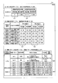
図2は、情報表示部の一例を示す説明図である。図2に示すように、情報表示部112は、特別図柄表示部201と、普通図柄表示部202と、保留数表示部203と、ラウンド数表示部204とを備える。各表示部201〜204にはそれぞれランプ表示器などが用いられる。
(Details of information display section)
FIG. 2 is an explanatory diagram illustrating an example of the information display unit. As shown in FIG. 2, the information display unit 112 includes a special symbol display unit 201, a normal symbol display unit 202, a hold number display unit 203, and a round number display unit 204. A lamp indicator or the like is used for each of the display units 201 to 204.
第1特別図柄表示部201aは、第1始動口105に遊技球が入賞することにより行われる大当たり判定の判定結果を示す第1特別図柄を表示するためのものであり、例えば8つのLED(Light Emitting Diode)ランプを備える。
The first special symbol display unit 201a is for displaying a first special symbol indicating a determination result of the jackpot determination performed by winning a game ball at the first starting port 105. For example, eight LED (Light (Emitting Diode) lamp.
例えば、第1特別図柄表示部201aは、第1特別図柄表示部201aの各LEDランプを図2において左から右へ流れるように順次点灯および消灯を繰り返すことにより第1特別図柄が変動表示中であることを示す。また、第1特別図柄表示部201aは、第1特別図柄を所定時間変動表示した後に所定のLEDランプのみを点灯させることにより第1特別図柄が停止表示されたことを示す。第1特別図柄の変動表示後にいずれのLEDランプを点灯させるかは、当該第1特別図柄の変動表示開始時に行われた大当たり判定の判定結果に応じて決定される。
For example, the first special symbol display unit 201a is steadily displaying the first special symbol by changing on and off sequentially so that each LED lamp of the first special symbol display unit 201a flows from left to right in FIG. Indicates that there is. In addition, the first special symbol display unit 201a indicates that the first special symbol is stopped and displayed by lighting only the predetermined LED lamp after the first special symbol is variably displayed for a predetermined time. Which LED lamp is lit after the first special symbol variation display is determined according to the determination result of the jackpot determination performed at the start of the first special symbol variation display.
例えば、遊技機100による大当たり判定では、下大入賞口16ラウンド(「ラウンド」のことを以下「R」と略す)確変大当たりと、下大入賞口8R確変大当たりと、下大入賞口8R通常大当たりと、下大入賞口2R確変大当たりと、上大入賞口8R確変大当たりとの5種類の大当たりのうちのいずれの大当たりとするかが判定される。
For example, in the jackpot determination by the gaming machine 100, the lower big prize opening 16 rounds ("R" is abbreviated as "R" hereinafter), the lower big prize opening 8R, the odd big jackpot, and the lower big prize opening 8R normal jackpot Then, it is determined which of the five types of jackpots is the big jackpot 2R probability variation jackpot and the upper prize winning port 8R probability variation jackpot.
そして、それぞれの大当たり毎に第1特別図柄表示部201aにおけるLEDランプの点灯態様(大当たり図柄)が遊技機100の製造者により予め定められている。第1特別図柄表示部201aは、第1始動口105に遊技球が入賞することにより行われた大当たり判定により上記のいずれかの大当たりに当選した場合、当該大当たりの種類に応じて予め定められた点灯態様でLEDランプを点灯させる。
And the lighting mode (big-hit symbol) of the LED lamp in the 1st special symbol display part 201a is predetermined by the manufacturer of the gaming machine 100 for each big-hit. The first special symbol display unit 201a is determined in advance according to the type of the jackpot when one of the above jackpots is won by the jackpot determination made by winning the game ball at the first starting port 105. The LED lamp is turned on in the lighting mode.
第2特別図柄表示部201bは、第2始動口106に遊技球が入賞することにより行われる大当たり判定の判定結果を示す第2特別図柄を表示するためのものであり、第1特別図柄表示部201aと同様に、例えば8つのLEDランプを備える。
The second special symbol display unit 201b is for displaying a second special symbol indicating a determination result of the jackpot determination performed by winning the game ball at the second starting port 106, and the first special symbol display unit As with 201a, for example, eight LED lamps are provided.
第2特別図柄表示部201bは、第2特別図柄表示部201bの各LEDランプを図2において左から右へ流れるように順次点灯および消灯を繰り返すことにより第2特別図柄が変動表示中であることを示す。また、第2特別図柄表示部201bは、第2特別図柄を所定時間変動表示した後に所定のLEDランプのみを点灯させることにより第2特別図柄が停止表示されたことを示す。第2特別図柄表示部201bは、第1特別図柄表示部201aと同様に、第2始動口106に遊技球が入賞することにより行われた大当たり判定により上記のいずれかの大当たりに当選した場合、当該大当たりの種類に応じて予め定められた点灯態様でLEDランプを点灯させる。
The second special symbol display unit 201b is steadily turning on and off so that each LED lamp of the second special symbol display unit 201b flows from left to right in FIG. Indicates. In addition, the second special symbol display unit 201b indicates that the second special symbol is stopped and displayed by lighting only a predetermined LED lamp after the second special symbol is variably displayed for a predetermined time. Similarly to the first special symbol display unit 201a, the second special symbol display unit 201b wins any of the above jackpots by the jackpot determination made by winning a game ball at the second starting port 106. The LED lamp is turned on in a predetermined lighting manner according to the jackpot type.
普通図柄表示部202は、ゲート108を遊技球が通過することにより行われる普通図柄判定の判定結果を示す普通図柄を表示するためのものであり、例えば「○」、「△」、「×」を示す3つのLEDランプを備える。
The normal symbol display unit 202 is for displaying a normal symbol indicating a determination result of the normal symbol determination performed by the game ball passing through the gate 108. For example, “O”, “Δ”, “X” is displayed. 3 LED lamps are provided.
普通図柄表示部202は、普通図柄表示部202の各LEDを「○」→「△」→「×」→「○」→…というように順次点灯および消灯を繰り返すことにより普通図柄が変動表示中であることを示す。また、普通図柄表示部202は、普通図柄を所定時間変動表示した後に所定のLEDランプのみを点灯させることにより普通図柄が停止表示されたことを示す。普通図柄の変動表示後にいずれのLEDランプを点灯させるかは、当該普通図柄の変動表示開始時に行われた普通図柄判定の判定結果に応じて決定される。
The normal symbol display unit 202 displays the normal symbols in a variable manner by repeatedly turning on and off the LEDs of the normal symbol display unit 202 in the order of “O” → “Δ” → “×” → “O” →. Indicates that Further, the normal symbol display unit 202 indicates that the normal symbol is stopped and displayed by lighting only the predetermined LED lamp after the normal symbol is displayed in a variable manner for a predetermined time. Which LED lamp is turned on after the normal symbol variation display is determined according to the determination result of the normal symbol determination performed at the start of the variation display of the normal symbol.
例えば、遊技機100による普通図柄判定では、普通図柄長開放当たりと、普通図柄短開放当たりとの2種類の普通図柄当たりのうちのいずれの普通図柄当たりとするかが判定される。そして、それぞれの普通図柄当たり毎に普通図柄表示部202におけるLEDランプの点灯態様が遊技機100の製造者により予め定められる。例えば、普通図柄表示部202は、普通図柄長開放当たりに当選した場合には「○」のLEDを点灯させ、普通図柄短開放当たりに当選した場合には「△」のLEDを点灯させる。
For example, in the normal symbol determination by the gaming machine 100, it is determined which of the two types of normal symbols per normal symbol length open and per normal symbol short open per normal symbol. And the lighting mode of the LED lamp in the normal symbol display part 202 is predetermined by the manufacturer of the gaming machine 100 for each normal symbol. For example, the normal symbol display unit 202 turns on the “◯” LED when winning per normal symbol length opening, and turns on the “Δ” LED when winning per normal symbol short opening.
保留数表示部203は、保留情報の数(以下「保留情報数」という)を表示するためのものであり、第1特別図柄保留数表示部203aと、第2特別図柄保留数表示部203bと、普通図柄保留数表示部203cとを備える。
The number-of-holds display unit 203 is for displaying the number of pieces of on-hold information (hereinafter referred to as “number of on-hold information”). The first special symbol hold number display unit 203a, the second special symbol hold number display unit 203b, And a normal symbol hold number display section 203c.
第1特別図柄保留数表示部203aは、特別図柄の変動表示中に遊技球が第1始動口105に入賞することにより記憶された保留情報数(以下「第1保留情報数」という)を表示する。第2特別図柄保留数表示部203bは、特別図柄の変動表示中に遊技球が第2始動口106に入賞することにより記憶された保留情報数(以下「第2保留情報数」という)を表示する。なお、以下において第1保留情報数と第2保留情報数とを合わせたものを「特図保留情報数」という。普通図柄保留数表示部203cは、普通図柄の変動表示中に遊技球がゲート108を通過することにより記憶される保留情報数(以下「普図保留情報数」という)を表示する。
The first special symbol hold number display unit 203a displays the number of hold information stored when the game ball wins the first start opening 105 during the special symbol variation display (hereinafter referred to as “first hold information number”). To do. The second special symbol number-of-holds display section 203b displays the number of reserved information stored when the game ball wins the second starting port 106 during the special symbol variation display (hereinafter referred to as "second number of reserved information"). To do. In the following, the sum of the number of the first holding information and the number of the second holding information is referred to as the “number of special figure holding information”. The normal symbol hold number display unit 203c displays the number of hold information stored when the game ball passes through the gate 108 during the normal symbol change display (hereinafter referred to as “the number of common figure hold information”).
遊技機100では第1保留情報数と第2保留情報数と普図保留情報数との上限数をそれぞれ「4」としている。このため、第1特別図柄保留数表示部203aと第2特別図柄保留数表示部203bと普通図柄保留数表示部203cとは、それぞれ4つのLEDランプからなる。そして、第1特別図柄保留数表示部203aと第2特別図柄保留数表示部203bと普通図柄保留数表示部203cとは、それぞれが対応する保留情報数と同数のLEDランプを点灯させる。
In the gaming machine 100, the upper limit number of the first hold information number, the second hold information number, and the usual hold information number is set to “4”. Therefore, the first special symbol reservation number display unit 203a, the second special symbol reservation number display unit 203b, and the normal symbol reservation number display unit 203c each include four LED lamps. And the 1st special symbol reservation number display part 203a, the 2nd special symbol reservation number display part 203b, and the normal symbol reservation number display part 203c light the LED lamp of the same number as the number of corresponding hold information respectively.
ラウンド数表示部204は大当たり遊技のラウンド数を表示する。遊技機100では16Rの大当たりと8Rの大当たりと2Rの大当たりとがあるので、ラウンド数表示部204は「16R」を表示するLEDランプ、「8R」を表示するLEDランプ、「2R」を表示するLEDランプを有する。そして、ラウンド数表示部204は16Rの大当たりに当選した場合には「16R」を表示するLEDランプを点灯させる。ラウンド数表示部204は8Rの大当たりに当選した場合には「8R」を表示するLEDランプを点灯させる。ラウンド数表示部204は2Rの大当たりに当選した場合には「2R」を表示するLEDランプを点灯させる。
The round number display unit 204 displays the number of rounds of the jackpot game. Since the gaming machine 100 has a jackpot of 16R, a jackpot of 8R, and a jackpot of 2R, the round number display unit 204 displays an LED lamp that displays “16R”, an LED lamp that displays “8R”, and “2R”. It has an LED lamp. Then, the round number display unit 204 turns on an LED lamp that displays “16R” when a 16R jackpot is won. When the round number display unit 204 wins the 8R jackpot, the LED lamp that displays “8R” is turned on. The round number display unit 204 turns on an LED lamp that displays “2R” when a 2R jackpot is won.
(遊技機の基本動作)
次に、遊技機100の基本動作について説明する。遊技機100は、遊技者により発射指示部材117が操作されると遊技領域103内に遊技球を発射する。遊技機100は、遊技球が第1始動口105や第2始動口106へ入賞すれば保留情報を取得して大当たり判定を行う。遊技機100は大当たり判定を行うと特別図柄表示部201において特別図柄を変動表示する。
(Basic operation of gaming machines)
Next, the basic operation of the gaming machine 100 will be described. The gaming machine 100 launches a game ball into the game area 103 when the launch instruction member 117 is operated by the player. The gaming machine 100 obtains holding information and makes a jackpot determination when the game ball wins the first starting port 105 or the second starting port 106. When the gaming machine 100 determines the jackpot, the special symbol display unit 201 displays the special symbol in a variable manner.
特別図柄の変動表示に伴って、遊技機100は画像表示部104において演出図柄(例えば3列の数字)を変動表示し、また演出図柄の変動表示中には大当たりへの信頼度を示すための各種演出(例えばリーチ演出)を行う。遊技機100は特別図柄を所定期間変動表示すると、大当たり判定の判定結果を示すように停止表示する。
Along with the special symbol variation display, the gaming machine 100 displays a variation of the effect symbol (for example, three columns of numbers) on the image display unit 104, and indicates the reliability of the jackpot during the variation symbol display of the effect symbol. Various effects (for example, reach effects) are performed. When the gaming machine 100 displays the special symbol in a variable manner for a predetermined period, the gaming machine 100 stops and displays the determination result of the jackpot determination.
そして、特別図柄の停止表示に伴って、遊技機100は演出図柄も大当たり判定の判定結果を示すように停止表示する。例えば、大当たりに落選していれば、遊技機100は、特別図柄をハズレ図柄で停止表示し、演出図柄をバラケ目(例えば「1・3・2」)で停止表示する。一方、大当たりに当選していれば、遊技機100は、特別図柄を大当たり図柄で停止表示し、演出図柄をゾロ目(例えば「1・1・1」)で停止表示する。
Then, along with the special symbol stop display, the gaming machine 100 stops and displays the effect symbols so as to show the determination result of the jackpot determination. For example, if the jackpot is lost, the gaming machine 100 stops and displays the special symbol as a lost symbol, and stops and displays the effect symbol as a break (for example, “1 / 3.2”). On the other hand, if the jackpot is won, the gaming machine 100 stops and displays the special symbol with the jackpot symbol, and stops and displays the effect symbol with a doublet (for example, “1 · 1 · 1”).
大当たりに当選したら、遊技機100は大当たり図柄の停止表示後に大当たり遊技を行う。大当たり遊技において、遊技機100は当選した大当たりの種類に応じた大入賞口を、当選した大当たりの種類に応じたR数分開放する。そして、遊技機100は開放された上大入賞口109aや下大入賞口109bに遊技球が1球入賞する毎に所定個数の賞球を払い出す。
If the jackpot is won, the gaming machine 100 plays a jackpot game after the jackpot symbol is stopped. In the jackpot game, the gaming machine 100 opens the winning prize opening corresponding to the type of the jackpot that has been won by the number R corresponding to the type of jackpot that has been won. The gaming machine 100 pays out a predetermined number of prize balls each time a game ball wins an open upper prize winning hole 109a or lower major prize winning hole 109b.
また、遊技機100は、下大入賞口16R確変大当たり、下大入賞口8R確変大当たり、下大入賞口2R確変大当たり、上大入賞口8R確変大当たりなどの確変大当たりに当選することにより行われる大当たり遊技には当該大当たり遊技後に10000回の大当たり判定を行うか次の大当たり遊技が行われるまで確変遊技状態となる。なお、10000回の大当たり判定により大当たりに当選しない確率は極めて低いため、実質的には遊技機100は確変大当たりに当選することにより行われる大当たり遊技後に次の大当たり遊技が行われるまで確変遊技状態となると言える。
In addition, the gaming machine 100 is a jackpot made by winning winning jackpots such as a lower winning prize opening 16R probability change jackpot, a lower winning prize opening 8R probability changing jackpot, a lower winning prize opening 2R probability changing jackpot, an upper winning prize opening 8R probability changing jackpot, etc. The game is in a promising game state until 10000 jackpot determinations are made after the jackpot game or until the next jackpot game is performed. Since the probability of not winning the jackpot by the 10000 jackpot determination is extremely low, the gaming machine 100 is substantially in a probabilistic gaming state until the next jackpot game is performed after the jackpot game performed by winning the odd bonus jackpot. I can say.
確変遊技状態であるとき、遊技機100は大当たりと判定する判定確率を高めた大当たり判定を行う。例えば、遊技機100は、確変遊技状態でないときには大当たりと判定する判定確率が1/250となる大当たり判定を行う一方、確変遊技状態であるときには大当たりと判定する判定確率が7/250となる大当たり判定を行う。
When in the probabilistic gaming state, the gaming machine 100 performs jackpot determination with an increased determination probability for determining jackpot. For example, the gaming machine 100 performs a jackpot determination with a determination probability of 1/250 when determining that it is a jackpot when not in the probability variation gaming state, while determining a jackpot determination with a determination probability of 7/250 when determining that the jackpot is in the probability variation gaming state. I do.
また、確変遊技状態であるとき、遊技機100は第2始動口106への遊技球の入賞機会を増加させる。例えば、遊技機100は確変遊技状態であるときには、確変遊技状態でないときよりも普通図柄当たり(長開放当たり)や普通図柄当たり(短開放当たり)と判定する判定確率が高く定められた普通図柄判定を行う。また、遊技機100は確変遊技状態であるときには、確変遊技状態でないときよりも普通図柄当たり(長開放当たり)や普通図柄当たり(短開放当たり)に当選した場合に普通電動役物107を開放させる期間を延長させる。さらに、遊技機100は普通図柄を変動表示させておく期間を短くすることにより、単位時間あたり(例えば1分間あたり)に行える普通図柄判定の判定回数を増加させてもよい。
In addition, when the game state is in a probable gaming state, the gaming machine 100 increases the chance of winning a game ball to the second start port 106. For example, when the gaming machine 100 is in the probability variation gaming state, the normal symbol determination with a higher determination probability for determining per ordinary symbol (per long opening) or per ordinary symbol (per short opening) than when not in the probability variation gaming state. I do. In addition, when the gaming machine 100 is in the probability variation gaming state, the ordinary electric accessory 107 is released when winning per normal symbol (per long opening) or per normal symbol (per short opening) than when not in the probability variation gaming state. Extend the period. Further, the gaming machine 100 may increase the number of determinations of the normal symbol determination that can be performed per unit time (for example, per minute) by shortening the period during which the normal symbol is variably displayed.
また、遊技機100は、下大入賞口8R通常大当たりに当選することにより行われる大当たり遊技には当該大当たり遊技後に30回の大当たり判定を行うか次の大当たり遊技が行われるまで時短遊技状態となる。時短遊技状態であるとき、遊技機100は、確変遊技状態とは異なり、大当たりと判定する判定確率が1/250となる大当たり判定を行うとともに第2始動口106への遊技球の入賞機会を増加させる。
In addition, the gaming machine 100 is in a short-time gaming state for the jackpot game performed by winning the bottom jackpot 8R normal jackpot until the jackpot game is determined 30 times after the jackpot game or the next jackpot game is performed. . When in the short-time gaming state, the gaming machine 100, unlike the probability variation gaming state, makes a jackpot determination with a determination probability of determining that it is 1/250 and increases the chances of winning a game ball to the second starting port 106 Let
また、遊技機100は発射された遊技球がゲート108を通過すれば、普通図柄判定を受ける権利に相当する普図保留情報を取得して普通図柄判定を行う。普通図柄判定を行うと、普通図柄表示部202において普通図柄を変動表示する。遊技機100は普通図柄を所定期間変動表示すると、普通図柄判定の判定結果を表すように停止表示する。前述のように、遊技機100は普通図柄当たり(長開放当たり)に当選していれば「○」図柄で、普通図柄当たり(短開放当たり)に当選していれば「△」図柄で、これらに落選していれば「×」図柄で停止表示する。普通図柄当たりに当選したら、遊技機100はこれらを表す図柄の停止表示後に当選した普通図柄当たりの種類に応じた期間だけ普通電動役物107を開放する。
In addition, when the launched game ball passes through the gate 108, the gaming machine 100 obtains the general symbol hold information corresponding to the right to receive the normal symbol determination and performs the normal symbol determination. When the normal symbol determination is performed, the normal symbol display unit 202 displays the normal symbol in a variable manner. When the gaming machine 100 displays the normal symbol in a predetermined period, the gaming machine 100 stops and displays the normal symbol determination result. As described above, the gaming machine 100 has a symbol “○” if it is won per regular symbol (per long opening), and “△” symbol if it is elected per ordinary symbol (per short opening). If it is lost, the display is stopped with the symbol “×”. When winning for each ordinary symbol, the gaming machine 100 releases the ordinary electric accessory 107 for a period corresponding to the type of each winning symbol after displaying the symbols representing these symbols.
(遊技機の機能的構成)
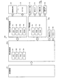
次に、遊技機100の機能的構成について説明する。図3は、本実施の形態の遊技機の機能的構成を示すブロック図である。図3に示すように、遊技機100は、権利記憶部301と、事前判定部302と、保留表示制御部303と、特別遊技判定部304と、図柄表示制御部305と、画像表示部104とを含む構成である。ここで、画像表示部104は、前述のように第1画像表示部104aと第1画像表示部104aよりも小さな表示領域を有する第2画像表示部104bとを備える。
(Functional configuration of gaming machine)
Next, a functional configuration of the gaming machine 100 will be described. FIG. 3 is a block diagram illustrating a functional configuration of the gaming machine according to the present embodiment. As shown in FIG. 3, the gaming machine 100 includes a right storage unit 301, a prior determination unit 302, a hold display control unit 303, a special game determination unit 304, a symbol display control unit 305, and an image display unit 104. It is the structure containing. Here, the image display unit 104 includes the first image display unit 104a and the second image display unit 104b having a smaller display area than the first image display unit 104a as described above.
権利記憶部301は、所定の始動領域を遊技球が通過することにより、遊技者にとって有利な特別遊技を行うか否かの特別遊技判定を受けるための権利を当該権利による特別遊技判定が行われるまで、所定数を上限に複数記憶可能な機能を有する。本実施の形態では一例として、所定の始動領域を第1始動口105や第2始動口106、特別遊技を大当たり遊技、特別遊技判定を大当たり判定、特別遊技判定を受けるための権利を保留情報とする。
The right storage unit 301 performs a special game determination based on the right to receive a special game determination as to whether or not to play a special game advantageous to the player when the game ball passes through a predetermined start area. Up to a predetermined number, a plurality of functions can be stored. In the present embodiment, as an example, the predetermined start area is the first start port 105 or the second start port 106, the special game is a jackpot game, the special game determination is a jackpot determination, and the right to receive the special game determination is reserved information. To do.
すなわち、この場合、権利記憶部301は、第1始動口105や第2始動口106に遊技球が入賞することにより保留情報を記憶する。また、権利記憶部301は記憶した保留情報を、当該保留情報を用いた大当たり判定が行われるまで保持する。例えば、本実施の形態において、保留情報には大当たり判定に用いられる当たり乱数や図柄乱数のほか、変動パターン判定に用いられる変動パターン乱数なども含まれる。変動パターン判定は、大当たり判定の判定結果を示す際の特別図柄の変動態様(例えば変動時間)を決定するための処理であり、その具体的な内容については後述する。
That is, in this case, the right storage unit 301 stores the hold information when the game ball wins the first starting port 105 or the second starting port 106. The right storage unit 301 holds the stored hold information until a jackpot determination using the hold information is performed. For example, in the present embodiment, the hold information includes not only winning random numbers and symbol random numbers used for jackpot determination, but also variation pattern random numbers used for variation pattern determination. The variation pattern determination is a process for determining the variation mode (for example, variation time) of the special symbol when the determination result of the jackpot determination is shown, and the specific contents thereof will be described later.
事前判定部302は、権利記憶部301に記憶された各権利による特別遊技判定の判定結果を事前判定する機能を有する。例えば、本実施の形態の場合、事前判定部302は権利記憶部301に保留情報が記憶された時点で、この保留情報を用いた大当たり判定で大当たりになるか否か、この保留情報を用いた大当たり判定の判定結果を示す際の特別図柄の変動態様などを判定する。
The prior determination unit 302 has a function of determining in advance the determination result of the special game determination based on each right stored in the right storage unit 301. For example, in the case of the present embodiment, the prior determination unit 302 uses the hold information to determine whether or not the jackpot determination using the hold information is a big win at the time when the hold information is stored in the right storage unit 301. The variation pattern of the special symbol when the determination result of the jackpot determination is shown is determined.
保留表示制御部303は、権利記憶部301に記憶された各権利に対応する保留画像を画像表示部104に表示する機能を有する。保留表示制御部303は各権利に対応する保留画像を通常表示態様と特殊表示態様とで表示することができる。ここで特殊表示態様は通常表示態様とは異なる表示態様である。すなわち、遊技者は通常表示態様であるか特殊表示態様であるかを判別できるようになっている。
The hold display control unit 303 has a function of displaying a hold image corresponding to each right stored in the right storage unit 301 on the image display unit 104. The hold display control unit 303 can display a hold image corresponding to each right in a normal display mode and a special display mode. Here, the special display mode is a display mode different from the normal display mode. That is, the player can determine whether the display mode is the normal display mode or the special display mode.
本実施の形態の場合、保留表示制御部303は保留情報が記憶されると、この保留情報に対応する保留アイコンを画像表示部104に表示する。例えば、保留表示制御部303は、所定条件を満たす保留情報が記憶されていないときには記憶中の各保留情報に対応する保留アイコンを通常表示態様で第2画像表示部104bに表示する。一方、保留表示制御部303は、所定条件を満たす保留情報が記憶されているときには当該保留情報に対応する保留アイコンを特殊表示態様で、他の保留情報に対応する保留アイコンを通常表示態様で、第1画像表示部104aに表示する。
In the case of the present embodiment, when the hold information is stored, the hold display control unit 303 displays a hold icon corresponding to the hold information on the image display unit 104. For example, when the hold information satisfying the predetermined condition is not stored, the hold display control unit 303 displays the hold icon corresponding to each stored hold information on the second image display unit 104b in the normal display mode. On the other hand, when the hold information satisfying the predetermined condition is stored, the hold display control unit 303 displays the hold icon corresponding to the hold information in a special display mode and the hold icon corresponding to other hold information in a normal display mode. It displays on the 1st image display part 104a.
例えば、保留表示制御部303は、所定条件を満たす保留情報が記憶されると、この保留情報に対応する保留アイコンを一旦、通常表示態様で表示する。このときには、所定条件を満たす保留情報に対応する保留アイコンも他の保留アイコンも通常表示態様で第2画像表示部104bに表示される。そして、保留表示制御部303はこれらの通常表示態様の保留アイコンを一斉に第1画像表示部104aに移動させて表示する。その後、保留表示制御部303は所定条件を満たす保留情報に対応する保留アイコンのみを特殊表示態様に変更して表示する。なお、保留表示制御部303による表示例については図4〜図6などを用いて後述する。
For example, when the hold information satisfying the predetermined condition is stored, the hold display control unit 303 temporarily displays the hold icon corresponding to the hold information in the normal display mode. At this time, the hold icon corresponding to the hold information satisfying the predetermined condition and other hold icons are displayed on the second image display unit 104b in the normal display mode. Then, the hold display control unit 303 moves these hold icons in the normal display mode to the first image display unit 104a at a time and displays them. Thereafter, the hold display control unit 303 changes only the hold icon corresponding to the hold information satisfying the predetermined condition to the special display mode and displays it. A display example by the hold display control unit 303 will be described later with reference to FIGS.
特別遊技判定部304は、権利記憶部301に記憶された権利の中の始動条件を満たした権利による特別遊技判定を行う機能を有する。例えば、本実施の形態の場合、特別遊技判定部304は権利記憶部301に保留情報を用いて大当たり判定を行う。権利記憶部301に記憶された各保留情報には、記憶された順序や、第1始動口105に遊技球が入賞することにより記憶されたか第2始動口106に遊技球が入賞することにより記憶されたかなどにより、大当たり判定を受ける判定順序が設定される。
The special game determination unit 304 has a function of performing a special game determination based on a right that satisfies a start condition among the rights stored in the right storage unit 301. For example, in the case of the present embodiment, the special game determination unit 304 makes a jackpot determination using the hold information in the right storage unit 301. Each hold information stored in the right storage unit 301 is stored in the stored order or when the game ball is won at the first start port 105 or when the game ball is won at the second start port 106. The determination order for receiving the jackpot determination is set depending on whether the determination is made.
具体的には、本実施の形態の場合、第2始動口106に遊技球が入賞することにより記憶された保留情報の方が、第1始動口105に遊技球が入賞することにより記憶された保留情報よりも優先して先に大当たり判定が行われるように判定順序が設定される。さらに、本実施の形態の場合、時系列的に先に記憶された保留情報の方が、後に記憶された保留情報よりも優先して先に大当たり判定が行われるように判定順序が設定される。このようにしてそれぞれの保留情報には判定順序が設定され、特別遊技判定部304は記憶されている保留情報の中で最も早い判定順序が設定された保留情報を用いて大当たり判定を行う。また、例えば、特別遊技判定部304は、大当たり遊技中でなく、且つ、特別図柄の変動中でないときに大当たり判定を行う。
Specifically, in the case of the present embodiment, the hold information stored by winning the game ball at the second starting port 106 is stored by winning the game ball at the first starting port 105. The determination order is set so that the jackpot determination is performed prior to the hold information. Furthermore, in the case of the present embodiment, the determination order is set so that the hold information stored earlier in time series is prioritized over the hold information stored later and the jackpot determination is performed first. . In this way, a determination order is set for each hold information, and the special game determination unit 304 performs a jackpot determination using the hold information for which the earliest determination order is set among the stored hold information. Further, for example, the special game determination unit 304 performs the jackpot determination when the jackpot game is not being played and the special symbol is not changing.
図柄表示制御部305は、特別遊技判定部304により特別遊技判定が行われた場合、第1画像表示部104aにおいて図柄を変動表示した後に当該特別遊技判定の判定結果を示すように停止表示する。例えば、本実施の形態の場合、図柄表示制御部305は、特別遊技判定部304により大当たり判定が行われると、第1画像表示部104aにおいて3つの演出図柄を変動表示した後に、これらを大当たり判定の判定結果を示す組み合わせとなるように停止表示する。
When the special game determination is performed by the special game determination unit 304, the symbol display control unit 305 displays the symbols in the first image display unit 104a and then stops and displays the determination result of the special game determination. For example, in the case of the present embodiment, when the special game determination unit 304 performs the big hit determination, the symbol display control unit 305 displays the three effect symbols in the first image display unit 104a, and then determines these jackpots. Are stopped and displayed so as to obtain a combination indicating the determination result.
また、図柄表示制御部305は、前述のように保留表示制御部303により所定条件を満たす保留情報に対応する保留アイコンが特殊表示態様に変更される場合、この変更前に演出図柄を縮小表示する。なお、図柄表示制御部305による表示例については図4〜図6などを用いて後述する。なお、本実施の形態の例では演出図柄を第2画像表示部104bへ移動させるとともに当該移動に伴って縮小表示するが、これに限らず、第1画像表示部104aに演出図柄を表示させた状態で縮小表示してもよい。
In addition, when the hold icon corresponding to the hold information satisfying the predetermined condition is changed to the special display mode by the hold display control unit 303 as described above, the symbol display control unit 305 displays the effect symbol in a reduced size before the change. . A display example by the symbol display control unit 305 will be described later with reference to FIGS. In the example of the present embodiment, the effect symbol is moved to the second image display unit 104b and reduced in accordance with the movement. However, the present invention is not limited to this, and the effect symbol is displayed on the first image display unit 104a. The state may be reduced and displayed.
(本実施の形態の遊技機による画像表示部の表示例)
次に、遊技機100(保留表示制御部303および図柄表示制御部305)による画像表示部104の表示例について説明する。図4は、本実施の形態の遊技機による画像表示部の表示例を示す説明図である。遊技機100は画像表示部104に演出図柄を表示する。図4(1)に示す例において、遊技機100は第1画像表示部104aに左演出図柄Ez1と中演出図柄Ez2と右演出図柄Ez3とを表示している。以下において、左演出図柄Ez1と中演出図柄Ez2と右演出図柄Ez3とを合わせたものを「演出図柄Ez1〜Ez3」と略す。
(Display example of image display unit by gaming machine of this embodiment)
Next, a display example of the image display unit 104 by the gaming machine 100 (the hold display control unit 303 and the symbol display control unit 305) will be described. FIG. 4 is an explanatory diagram showing a display example of the image display unit by the gaming machine of the present embodiment. The gaming machine 100 displays the effect symbol on the image display unit 104. In the example shown in FIG. 4A, the gaming machine 100 displays a left effect symbol Ez1, a middle effect symbol Ez2, and a right effect symbol Ez3 on the first image display unit 104a. Hereinafter, a combination of the left effect symbol Ez1, the middle effect symbol Ez2, and the right effect symbol Ez3 is abbreviated as “effect symbol Ez1 to Ez3”.
演出図柄Ez1〜Ez3は大当たり判定の判定結果を遊技者に示すためのものであり、例えば停止表示されたときに数字や漢字や平仮名や片仮名やアルファベット等の文字を表す。本実施の形態では、演出図柄Ez1〜Ez3のそれぞれは停止表示されたときに「1」から「5」までの数字を表すものとする。図4(1)に示す例では、左演出図柄Ez1は「1」を表し、中演出図柄Ez2は「2」を表し、右演出図柄Ez3は「3」を表している。
The production symbols Ez1 to Ez3 are used to show the player the determination result of the jackpot determination, and represent characters such as numbers, kanji, hiragana, katakana, and alphabets when stopped. In the present embodiment, each of the effect symbols Ez1 to Ez3 represents a number from “1” to “5” when stopped. In the example shown in FIG. 4 (1), the left effect symbol Ez1 represents “1”, the middle effect symbol Ez2 represents “2”, and the right effect symbol Ez3 represents “3”.
遊技機100は大当たり判定を行うと演出図柄Ez1〜Ez3を変動表示する。例えば、遊技機100は演出図柄Ez1〜Ez3の変動表示中には「1」から「5」までの数字が順次、表示画面の上方から下方へスクロールしていくように表示する。すなわち、遊技機100は、演出図柄Ez1〜Ez3のそれぞれが停止表示時にいずれの数字を表すかを遊技者が予測困難な態様で表示することにより、これらの変動表示を行う。
When the gaming machine 100 makes a jackpot determination, the effect symbols Ez1 to Ez3 are variably displayed. For example, the gaming machine 100 displays the numbers from “1” to “5” sequentially scrolling from the top to the bottom of the display screen during the variation display of the effect symbols Ez1 to Ez3. In other words, the gaming machine 100 performs these variable displays by displaying in a manner that it is difficult for the player to predict which numbers each of the effect symbols Ez1 to Ez3 represents during stop display.
遊技機100は、演出図柄Ez1〜Ez3を所定期間(例えば後述の変動パターンに応じた期間)変動表示してから、変動表示直前に行った大当たり判定の判定結果を示すように停止表示する。演出図柄Ez1〜Ez3の停止表示に際し、例えば、遊技機100は、左演出図柄Ez1→右演出図柄Ez3→中演出図柄Ez2といった順序で、各演出図柄を一つずつ停止表示させていく。
The gaming machine 100 displays the effect symbols Ez <b> 1 to Ez <b> 3 in a predetermined period (for example, a period according to a later-described fluctuation pattern), and then stops and displays the determination result of the jackpot determination performed immediately before the fluctuation display. When the effect symbols Ez1 to Ez3 are stopped and displayed, for example, the gaming machine 100 stops and displays each effect symbol one by one in the order of left effect symbol Ez1 → right effect symbol Ez3 → middle effect symbol Ez2.
なお、これに限らず、遊技機100は左演出図柄Ez1と右演出図柄Ez3とを同時に停止表示させてから中演出図柄Ez2を停止表示させるようにしてもよいし、演出図柄Ez1〜Ez3を同時に停止表示させてもよい。
However, the present invention is not limited to this, and the gaming machine 100 may stop and display the left effect symbol Ez1 and the right effect symbol Ez3 at the same time, and then stop and display the middle effect symbol Ez2 or may simultaneously display the effect symbols Ez1 to Ez3. A stop display may be displayed.
大当たり判定により大当たりと判定した場合、遊技機100は演出図柄Ez1〜Ez3を大当たりの組み合わせとなるように停止表示する。大当たりの組み合わせとしては、演出図柄Ez1〜Ez3が同一の数字を表す組み合わせ(所謂「ゾロ目」。例えば「1・1・1」)を例示することができる。例えば、遊技機100は大当たりの組み合わせで停止表示させる場合、大当たりの組み合わせの停止表示前に、左演出図柄Ez1と右演出図柄Ez3とが同一の数字を表すように停止表示し、且つ、中演出図柄Ez2の変動表示を維持して(所謂「リーチ状態」として)、リーチ演出を行う。
When it is determined that the jackpot is determined to be a jackpot, the gaming machine 100 stops and displays the effect symbols Ez1 to Ez3 so as to be a jackpot combination. Examples of the jackpot combination include combinations in which the production symbols Ez1 to Ez3 represent the same number (a so-called “zolo”, for example, “1 · 1 · 1”). For example, when the gaming machine 100 is stopped and displayed in a jackpot combination, the left effect symbol Ez1 and the right effect symbol Ez3 are stopped and displayed so as to represent the same number before the stoppage display of the jackpot combination, and the medium effect The display of the pattern Ez2 is maintained (so-called “reach state”), and the reach effect is performed.
一方、大当たり判定によりハズレと判定した場合、遊技機100は演出図柄Ez1〜Ez3をハズレの組み合わせとなるように停止表示する。ハズレの組み合わせは大当たりの組み合わせと異なる組み合わせであり、例えば演出図柄Ez1〜Ez3のそれぞれが異なる数字を表す組み合わせ(所謂「バラケ目」。例えば「3・1・2」)とすることができる。以下、このようにバラケ目が停止表示されるハズレ(リーチ演出が行われないハズレ)を「ノーマルハズレ」という。
On the other hand, when it is determined that the game is lost due to the jackpot determination, the gaming machine 100 stops and displays the production symbols Ez1 to Ez3 so as to be a combination of the lost games. The lost combination is a combination different from the jackpot combination, and for example, each of the production symbols Ez1 to Ez3 can represent a different number (a so-called “separation”, for example, “3 · 1 · 2”). Hereinafter, the loss in which the break eyes are stopped and displayed in this way (the loss in which the reach effect is not performed) is referred to as “normal loss”.
また、ハズレの組み合わせには上記バラケ目のほか、リーチハズレ目もある。このリーチハズレ目は、例えば左演出図柄Ez1と右演出図柄Ez3とが同一の数字を表し且つ中演出図柄Ez2が当該数字と異なる数字を表す組み合わせ(所謂「リーチハズレ目」。例えば「1・2・1」)とすることができる。例えば、遊技機100はリーチハズレ目で停止表示させる場合、大当たりの組み合わせを停止表示させる場合と同様、リーチハズレ目の停止表示前にリーチ状態として、リーチ演出を行う。以下、このようにリーチハズレ目が停止表示されるハズレ(リーチ演出が行われるハズレ)を「リーチハズレ」という。
In addition, the combination of loses includes reach loses as well as the above-mentioned breaks. This reach lose eye is, for example, a combination in which the left effect symbol Ez1 and the right effect symbol Ez3 represent the same number and the middle effect symbol Ez2 represents a number different from the number (so-called “reach lose eye”. For example, “1.2.1. )). For example, in the case where the gaming machine 100 is stopped and displayed at the reach lose eye, the reach effect is performed in the reach state before the reach lose eye stop display, similarly to the case where the jackpot combination is stopped and displayed. Hereinafter, the loss in which the reach loss eye is stopped and displayed (the loss in which the reach effect is performed) is referred to as “reach loss”.
また、遊技機100は画像表示部104に保留表示を表示する。この保留表示は、特図保留情報数を示すためのものであり、例えば、特図保留情報数と同数の保留アイコンにより構成される。例えば、図4(1)に示す例において、遊技機100は第2画像表示部104bに保留表示Hを表示している。この保留表示Hは、第1保留表示H1と第2保留表示H2とからなる。
Further, the gaming machine 100 displays a hold display on the image display unit 104. This hold display is for indicating the number of special figure hold information, and is constituted by, for example, the same number of hold icons as the number of special figure hold information. For example, in the example shown in FIG. 4A, the gaming machine 100 displays the hold display H on the second image display unit 104b. The hold display H includes a first hold display H1 and a second hold display H2.
第1保留表示H1は第1保留表示数と同数の保留アイコンIにより構成される。ここで第1保留情報数は、第1始動口105に遊技球が入賞することにより取得され、且つ、当該取得時から現在に至るまで大当たり判定に用いられていない保留情報の数である。図4(1)には、第1保留表示H1が4つの保留アイコンIにより構成されている例を示しており、これは第1保留情報数が「4」であることを表している。
The first hold display H1 includes the same number of hold icons I as the first hold display number. Here, the number of first hold information is the number of hold information acquired by winning a game ball at the first starting port 105 and not being used for jackpot determination from the acquisition time to the present. FIG. 4A shows an example in which the first hold display H1 includes four hold icons I, which indicates that the number of first hold information is “4”.
第2保留表示H2は第2保留表示数と同数の保留アイコンIにより構成される。ここで第2保留情報数は、第2始動口106に遊技球が入賞することにより取得され、且つ、当該取得時から現在に至るまで大当たり判定に用いられていない保留情報の数である。図4(1)には、第2保留表示H2が0の保留アイコンIにより構成されている例を示しており、これは第2保留情報数が「0」であることを表している。
The second hold display H2 includes the same number of hold icons I as the second hold display number. Here, the second number of on-hold information is the number of on-hold information that is acquired by winning a game ball at the second starting port 106 and that has not been used for jackpot determination from the time of acquisition until the present. FIG. 4 (1) shows an example in which the second hold display H2 is constituted by a hold icon I with 0, which indicates that the number of second hold information is “0”.
遊技機100において、第1保留情報数と第2保留情報数との上限はそれぞれ「4」とされる。このため、遊技機100は、それぞれが最大で4つの保留アイコンIからなる第1保留表示H1と第2保留表示H2とを表示可能である。
In the gaming machine 100, the upper limit of the number of first hold information and the number of second hold information is “4”, respectively. For this reason, the gaming machine 100 can display the first hold display H1 and the second hold display H2 each consisting of a maximum of four hold icons I.
なお、例えば、第1保留表示H1におけるそれぞれの保留アイコンIは、大当たり判定を受ける判定順序が早い保留情報に対応するものから、図4中左側から配置されているものとする。同様に、第2保留表示H2におけるそれぞれの保留アイコンIは、大当たり判定を受ける判定順序が早い保留情報に対応するものから、図4中左側から配置されているものとする。
For example, it is assumed that each hold icon I in the first hold display H1 is arranged from the left side in FIG. 4 from the one corresponding to the hold information with the early determination order of receiving the big hit determination. Similarly, it is assumed that the respective hold icons I in the second hold display H2 are arranged from the left side in FIG. 4 from the one corresponding to the hold information whose determination order for receiving the jackpot determination is early.
また、図4(2)に示すように、遊技機100は第1画像表示部104aに保留表示Hを表示することもできる。前述のように、第1画像表示部104aは第2画像表示部104bよりも表示領域が大きい。このため、遊技機100は第1画像表示部104aに保留表示Hを表示する場合、第2画像表示部104bに保留表示Hを表示する場合に比べて、保留表示Hの拡大表示が可能である。
In addition, as shown in FIG. 4B, the gaming machine 100 can also display the hold display H on the first image display unit 104a. As described above, the first image display unit 104a has a larger display area than the second image display unit 104b. For this reason, when the gaming machine 100 displays the holding display H on the first image display unit 104a, the gaming machine 100 can display the holding display H in an enlarged manner as compared with the case where the holding display H is displayed on the second image display unit 104b. .
また、図4(2)に示すように、遊技機100は第2画像表示部104bに演出図柄Ez1〜Ez3を表示することもできる。なお、図4(2)に示す例では、演出図柄Ez1〜Ez3を下白抜き矢印にて表している。以下において、このように演出図柄Ez1〜Ez3を下白抜き矢印にて表した場合、これは演出図柄Ez1〜Ez3が変動表示されていることを表す。
As shown in FIG. 4 (2), the gaming machine 100 can also display the effect symbols Ez1 to Ez3 on the second image display unit 104b. In the example shown in FIG. 4 (2), the production symbols Ez1 to Ez3 are represented by lower white arrows. In the following, when the effect symbols Ez1 to Ez3 are represented by the lower white arrows as described above, this indicates that the effect symbols Ez1 to Ez3 are displayed in a variable manner.
遊技機100は第1画像表示部104aに保留表示Hを表示する際、第1画像表示部104aに演出図柄Ez1〜Ez3を表示していると、保留表示Hと演出図柄Ez1〜Ez3とが重なり、これらが遊技者にとって見づらいものとなるおそれがある。そこで、遊技機100は第1画像表示部104aに保留表示Hを表示する際には、第2画像表示部104bに演出図柄Ez1〜Ez3を表示する。これにより、遊技機100は保留表示Hと演出図柄Ez1〜Ez3とが重なり、これらが遊技者にとって見づらいものとなってしまうことを防止することができる。
When the gaming machine 100 displays the hold display H on the first image display unit 104a, if the effect symbols Ez1 to Ez3 are displayed on the first image display unit 104a, the hold display H and the effect symbols Ez1 to Ez3 overlap. These may be difficult for the player to see. Therefore, when the gaming machine 100 displays the hold display H on the first image display unit 104a, it displays the effect symbols Ez1 to Ez3 on the second image display unit 104b. Thereby, the gaming machine 100 can prevent the hold display H and the effect symbols Ez1 to Ez3 from overlapping, and these are difficult to see for the player.
また、第2画像表示部104bは第1画像表示部104aよりも表示領域が小さい。そこで、例えば、遊技機100は第2画像表示部104bに演出図柄Ez1〜Ez3を表示する場合、第1画像表示部104aに演出図柄Ez1〜Ez3を表示する場合に比べて、演出図柄Ez1〜Ez3を縮小表示する。具体的には、この場合、遊技機100は、演出図柄Ez1〜Ez3の全体が第2画像表示部104bの表示領域内に収まるように、演出図柄Ez1〜Ez3を縮小表示する。これにより、遊技機100は表示領域の縮小に伴って演出図柄Ez1〜Ez3の全体が表示されなくなってしまうことを防止することができる。
The second image display unit 104b has a smaller display area than the first image display unit 104a. Thus, for example, when the gaming machine 100 displays the effect symbols Ez1 to Ez3 on the second image display unit 104b, the effect symbols Ez1 to Ez3 compared to the case where the effect symbols Ez1 to Ez3 are displayed on the first image display unit 104a. Is displayed in a reduced size. Specifically, in this case, the gaming machine 100 displays the effect symbols Ez1 to Ez3 in a reduced size so that the entire effect symbols Ez1 to Ez3 are within the display area of the second image display unit 104b. Thereby, the gaming machine 100 can prevent the entire effect symbols Ez1 to Ez3 from being displayed as the display area is reduced.
(本実施の形態の遊技機による演出例)
次に、遊技機100による演出例について説明する。図5は、本実施の形態の遊技機による演出例を示す説明図(その1)である。図6は、本実施の形態の遊技機による演出例を示す説明図(その2)である。
(Example of effects produced by the gaming machine of this embodiment)
Next, an example of effects produced by the gaming machine 100 will be described. FIG. 5 is an explanatory diagram (No. 1) showing an example of an effect produced by the gaming machine according to the present embodiment. FIG. 6 is an explanatory diagram (No. 2) showing an example of an effect produced by the gaming machine of the present embodiment.
図5(t1)では、演出図柄Ez1〜Ez3がハズレの組み合わせで第1画像表示部104aに停止表示されており、4つの保留アイコンIからなる保留表示Hが第2画像表示部104bに表示されている。なお、例えば、この保留アイコンIは全て第1保留表示H1のものであるとする。
In FIG. 5 (t1), the production symbols Ez1 to Ez3 are stopped and displayed on the first image display unit 104a by a combination of loss, and the hold display H including the four hold icons I is displayed on the second image display unit 104b. ing. For example, it is assumed that all the hold icons I are of the first hold display H1.
図5(t1)の状態において遊技機100は大当たり判定を行うと、図5(t2)に示すように第1画像表示部104aにて演出図柄Ez1〜Ez3の変動表示を開始する。なお、遊技機100は、この大当たり判定においてハズレと判定し、演出図柄Ez1〜Ez3をバラケ目で停止表示させると決定したものとする。すなわち、遊技機100は今回の演出図柄Ez1〜Ez3の変動表示させている間にリーチ演出を行わないと決定したものとする。また、遊技機100は、大当たり判定を行うことにより図5(t1)の状態から特図保留情報数(この場合、第1保留情報数)が「1」減少したので、図5(t2)では3つの保留アイコンIからなる保留表示Hを第2画像表示部104bに表示している。
When the gaming machine 100 makes a jackpot determination in the state of FIG. 5 (t1), as shown in FIG. 5 (t2), the first image display unit 104a starts variable display of the effect symbols Ez1 to Ez3. Note that it is assumed that the gaming machine 100 determines that the game has been lost in the jackpot determination and stops the effect symbols Ez1 to Ez3 to be displayed in a discrete manner. In other words, it is assumed that the gaming machine 100 determines not to perform the reach effect while the current effect symbols Ez1 to Ez3 are variably displayed. Further, the gaming machine 100 performs the jackpot determination, and the number of special figure hold information (in this case, the number of first hold information) is reduced by “1” from the state of FIG. 5 (t1). A hold display H including three hold icons I is displayed on the second image display unit 104b.
例えば、遊技機100はこのようにリーチ演出を行わない図柄変動において、図5(t3)に示すように保留表示Hを第1画像表示部104aに移動させて表示する。また、このとき、遊技機100は図5(t3)に示すように演出図柄Ez1〜Ez3を第2画像表示部104bに移動させて表示する。
For example, the gaming machine 100 moves and displays the hold display H on the first image display unit 104a as shown in FIG. 5 (t3) in such a symbol variation that does not perform the reach effect. At this time, the gaming machine 100 moves the effect symbols Ez1 to Ez3 to the second image display unit 104b and displays them as shown in FIG. 5 (t3).
その後、遊技機100は図6(t4)に示すように遊技者に演出ボタン118を押下するように指示する。遊技者がこの指示にしたがって演出ボタン118を押下すると、遊技機100は図6(t5)に示すようにいずれかの保留アイコンIの表示態様を変化させる。いずれの保留アイコンIの表示態様を変化させるかは、それぞれの保留アイコンIに対応する保留情報の事前判定結果によって決定される。
Thereafter, the gaming machine 100 instructs the player to press the effect button 118 as shown in FIG. 6 (t4). When the player presses the effect button 118 in accordance with this instruction, the gaming machine 100 changes the display mode of one of the hold icons I as shown in FIG. 6 (t5). Which of the hold icons I is to be displayed is determined based on a result of prior determination of hold information corresponding to each hold icon I.
ここでは、遊技機100は現在記憶している保留情報のうち大当たり判定を受ける判定順序が2番目の保留情報の事前判定結果が所定条件を満たしていた(例えば事前判定により大当たりやリーチ演出用の変動パターンと判定された)とする。この場合、遊技機100は所定条件を満たすと判定した保留情報、すなわち、図6(t5)に示すように左から2つ目の保留アイコンIの表示態様を、通常表示態様の「白色円形」から特殊表示態様の「雪だるま」に変更する。これにより、遊技機100は、図6(t5)に示す左から2つ目の保留アイコンIに対応する保留情報を用いた大当たり判定に対する遊技者の期待感を高めることができる。
Here, in the gaming machine 100, the pre-determination result of the second hold information whose determination order for receiving the jackpot determination among the currently stored hold information satisfies the predetermined condition (for example, for the jackpot or reach effect by the pre-determination) Determined as a variation pattern). In this case, the gaming machine 100 determines that the hold information determined to satisfy the predetermined condition, that is, the display mode of the second hold icon I from the left as shown in FIG. To “Snowman” in the special display mode. Thereby, the gaming machine 100 can increase the player's expectation for the jackpot determination using the hold information corresponding to the second hold icon I from the left shown in FIG. 6 (t5).
保留アイコンIの表示態様を変更すると、遊技機100は図6(t6)に示すように保留表示Hを第2画像表示部104bに移動させて表示する。また、このとき、遊技機100は図6(t6)に示すように演出図柄Ez1〜Ez3を第1画像表示部104aに移動させて表示する。そして、遊技機100は図6(t7)に示すように演出図柄Ez1〜Ez3をバラケ目で停止表示する。
When the display mode of the hold icon I is changed, the gaming machine 100 moves the hold display H to the second image display unit 104b and displays it as shown in FIG. 6 (t6). At this time, the gaming machine 100 moves the effect symbols Ez1 to Ez3 to the first image display unit 104a and displays them as shown in FIG. 6 (t6). Then, the gaming machine 100 stops and displays the effect symbols Ez1 to Ez3 as shown in FIG. 6 (t7).
このように遊技機100は保留表示Hによる演出(保留アイコンIの表示態様の変更)を行う場合、保留表示Hを第1画像表示部104aに表示する。ここで、第1画像表示部104aは通常時に保留表示Hが表示される第2画像表示部104bよりも大きな表示領域を有しており、遊技機100はこの表示領域の拡大に伴って保留表示Hを拡大表示させる。これにより、遊技機100は保留表示Hによる演出を行う場合にこの保留表示Hを通常時よりも目立つものとすることができ、保留表示Hによる演出の演出効果を高めることができる。なお、以下において保留表示Hによる演出を「保留表示演出」と略す。さらに、遊技機100は保留表示演出の際には演出図柄Ez1〜Ez3を縮小表示することで演出図柄Ez1〜Ez3を目立ちにくいものとし、保留表示Hを相対的に目立ち易いものとして、保留表示演出の演出効果を高めることができる。
In this way, when the gaming machine 100 performs an effect by the hold display H (change of the display mode of the hold icon I), the game display 100 displays the hold display H on the first image display unit 104a. Here, the first image display unit 104a has a larger display area than the second image display unit 104b in which the hold display H is normally displayed, and the gaming machine 100 displays the hold display as the display area expands. H is enlarged and displayed. Thereby, the gaming machine 100 can make the hold display H stand out from the normal time when performing the effect by the hold display H, and can enhance the effect of the effect by the hold display H. In the following, the production by the hold display H is abbreviated as “hold display production”. Further, the gaming machine 100 reduces the effect symbols Ez1 to Ez3 during the hold display effect so that the effect symbols Ez1 to Ez3 are less noticeable, and the hold display H is relatively less noticeable. The production effect can be enhanced.
なお、前述の例では図6(t6)にて演出図柄Ez1〜Ez3を第1画像表示部104aに移動させて、その後、図6(t7)のように第1画像表示部104aにて停止表示するようにしたがこれに限らない。例えば、遊技機100は前述のように大当たり判定においてハズレと判定し、演出図柄Ez1〜Ez3をバラケ目で停止表示させる場合に保留表示演出を行う。したがって、保留表示演出が行われた図柄変動において停止される出目はバラケ目となり、遊技者にとってはがっかりする出目である。したがって、このように遊技者をがっかりさせる出目を不必要に強調してしまうことを防止する観点から、遊技機100は保留表示演出を行うと演出図柄Ez1〜Ez3を第2画像表示部104bに移動させるとともに当該移動に伴って縮小表示し、縮小表示した状態で第2画像表示部104bにて停止表示させてもよい。このように構成した場合、例えば、遊技機100は保留表示演出を行った図柄変動の次の図柄変動開始時に、演出図柄Ez1〜Ez3を第1画像表示部104aに戻す(縮小表示も解除する)。
In the above-described example, the production symbols Ez1 to Ez3 are moved to the first image display unit 104a in FIG. 6 (t6), and then stopped and displayed on the first image display unit 104a as shown in FIG. 6 (t7). However, it is not limited to this. For example, the gaming machine 100 determines that it is lost in the jackpot determination as described above, and performs the hold display effect when the effect symbols Ez1 to Ez3 are stopped and displayed with a break. Therefore, the outcome that is stopped in the symbol variation in which the hold display effect is performed becomes a break-away, which is a disappointing outcome for the player. Therefore, from the standpoint of preventing unnecessary emphasis on the outcome that disappoints the player in this way, when the gaming machine 100 performs the hold display effect, the effect symbols Ez1 to Ez3 are displayed on the second image display unit 104b. The second image display unit 104b may stop the display in a state where the image is moved and reduced along with the movement. When configured in this way, for example, the gaming machine 100 returns the effect symbols Ez1 to Ez3 to the first image display unit 104a at the start of the symbol variation next to the symbol variation for which the hold display effect has been performed (the reduced display is also released). .
(遊技機のハードウェア構成の一例)
次に、遊技機100の詳細なハードウェア構成の一例について説明する。図7は、遊技機のハードウェア構成の一例を示す説明図(その1)である。遊技機100は、遊技の進行を制御する主制御部701と、賞球の払い出しなどを制御する賞球制御部702と、演出を制御する演出制御部703とを備える。
(Example of hardware configuration of gaming machine)
Next, an example of a detailed hardware configuration of the gaming machine 100 will be described. FIG. 7 is an explanatory diagram (part 1) illustrating an example of a hardware configuration of the gaming machine. The gaming machine 100 includes a main control unit 701 that controls the progress of the game, a prize ball control unit 702 that controls the payout of prize balls, and an effect control unit 703 that controls the production.
(主制御部について)
まず、主制御部701について説明する。主制御部701は、CPU(Central Processing Unit)711と、ROM(Read Only Memory)712と、RAM(Random Access Memory)713と、不図示の入出力インターフェース(I/O)などを備える。
(Main control unit)
First, the main control unit 701 will be described. The main control unit 701 includes a CPU (Central Processing Unit) 711, a ROM (Read Only Memory) 712, a RAM (Random Access Memory) 713, an input / output interface (I / O) (not shown), and the like.
CPU711は主制御部701の全体の制御を司る。ROM712は遊技の進行に関するプログラムやデータなどを記憶する。例えば、ROM712は図8に示す各種テーブルなどを記憶する。RAM713はCPU711のワークエリアとして使用される。CPU711はROM712からプログラムやデータを読み出し、RAM713をワークエリアとして使用しながら読み出したプログラムを実行する。
The CPU 711 governs overall control of the main control unit 701. The ROM 712 stores programs and data related to the progress of the game. For example, the ROM 712 stores various tables shown in FIG. The RAM 713 is used as a work area for the CPU 711. The CPU 711 reads the program and data from the ROM 712 and executes the read program while using the RAM 713 as a work area.
主制御部701には遊技球を検出する各種スイッチ(以下「SW」と略す)が接続される。例えば、主制御部701には、第1始動口SW714aと、第2始動口SW714bとが接続される。第1始動口SW714aは第1始動口105へ入賞した遊技球を検出するSWである。第2始動口SW714bは第2始動口106へ入賞した遊技球を検出するSWである。
Various switches (hereinafter abbreviated as “SW”) for detecting a game ball are connected to the main control unit 701. For example, a first start port SW714a and a second start port SW714b are connected to the main control unit 701. The first start port SW 714 a is a SW that detects a game ball that has won the first start port 105. The second start port SW 714 b is a SW that detects a game ball that has won the second start port 106.
さらに、主制御部701には、ゲートSW715と、大入賞口SW716と、普通入賞口SW717とが接続される。ゲートSW715はゲート108を通過した遊技球を検出するSWである。また、大入賞口SW716は上大入賞口SWと下大入賞口SWとからなる。ここで、上大入賞口SWは上大入賞口109aへ入賞した遊技球を検出するSWであり、下大入賞口SWは下大入賞口109bへ入賞した遊技球を検出するSWである。また、普通入賞口SW717は普通入賞口110へ入賞した遊技球を検出するSWである。
Further, the main control unit 701 is connected to a gate SW 715, a special winning opening SW 716, and a normal winning opening SW 717. The gate SW 715 is a SW that detects a game ball that has passed through the gate 108. The big prize opening SW 716 includes an upper prize winning opening SW and a lower prize winning opening SW. Here, the upper large winning opening SW is a SW that detects a game ball won in the upper large winning opening 109a, and the lower large winning opening SW is a SW that detects a gaming ball won in the lower large winning opening 109b. The normal winning opening SW 717 is a SW for detecting a game ball that has won the normal winning opening 110.
各種SW714〜717は遊技球を検出したか否かを示す検出信号を主制御部701へ入力する。主制御部701は各種SW714〜717から入力される検出信号に基づいて保留情報を記憶したり、賞球制御部702に対して賞球の払い出し指示を行ったりする。各種SW714〜717には近接スイッチなどを用いることができる。
The various SWs 714 to 717 input a detection signal indicating whether or not a game ball has been detected to the main control unit 701. The main control unit 701 stores the hold information based on the detection signals input from the various SWs 714 to 717, and issues a prize ball payout instruction to the prize ball control unit 702. A proximity switch or the like can be used for the various SWs 714 to 717.
主制御部701には電動役物を動作させる各種ソレノイドが接続される。例えば、主制御部701には、普通電動役物ソレノイド718が接続される。普通電動役物ソレノイド718は普通電動役物107を開閉動作させるソレノイドである。また、主制御部701には大入賞口ソレノイド719が接続される。大入賞口ソレノイド719は、上大入賞口ソレノイドと下大入賞口ソレノイドとからなる。ここで、上大入賞口ソレノイドは上大入賞口109aを開閉動作させるソレノイドであり、下大入賞口ソレノイドは下大入賞口109bを開閉動作させるソレノイドである。
The main controller 701 is connected to various solenoids that operate the electric accessory. For example, a normal electric accessory solenoid 718 is connected to the main control unit 701. The ordinary electric accessory solenoid 718 is a solenoid that opens and closes the ordinary electric accessory 107. The main control unit 701 is connected with a special prize opening solenoid 719. The big prize winning solenoid 719 includes an upper prize winning solenoid and a lower prize winning solenoid. Here, the upper big prize opening solenoid is a solenoid that opens and closes the upper big prize opening 109a, and the lower big prize opening solenoid is a solenoid that opens and closes the lower big prize opening 109b.
各種ソレノイド718,719は主制御部701から入力された電気エネルギーを機械的な運動に変換し、普通電動役物107や上大入賞口109aや下大入賞口109bを開閉動作させる。
The various solenoids 718 and 719 convert the electric energy input from the main control unit 701 into mechanical motion, and open / close the normal electric accessory 107, the upper prize winning port 109a, and the lower major prize winning port 109b.
主制御部701には情報表示部112が接続される。前述のように、情報表示部112は、特別図柄表示部201(第1特別図柄表示部201aと第2特別図柄表示部201b)と、普通図柄表示部202と、保留数表示部203と、ラウンド数表示部204とを備える。
An information display unit 112 is connected to the main control unit 701. As described above, the information display unit 112 includes the special symbol display unit 201 (the first special symbol display unit 201a and the second special symbol display unit 201b), the normal symbol display unit 202, the reserved number display unit 203, the round A number display unit 204.
また、主制御部701には盤用外部情報端子基板791が接続される。主制御部701は盤用外部情報端子基板791を介して各種情報を外部に出力することができる。例えば、主制御部701は主制御基板によってその機能を実現することができる。
Further, a board external information terminal board 791 is connected to the main controller 701. The main control unit 701 can output various types of information to the outside via the panel external information terminal board 791. For example, the main control unit 701 can realize its function by the main control board.
(賞球制御部について)
次に、賞球制御部702について説明する。賞球制御部702は、CPU721と、ROM722と、RAM723と、不図示の入出力インターフェースなどを備える。
(About the prize ball controller)
Next, the winning ball control unit 702 will be described. The prize ball control unit 702 includes a CPU 721, a ROM 722, a RAM 723, an input / output interface (not shown), and the like.
CPU721は賞球制御部702の全体の制御を司る。ROM722は賞球の払い出しなどに関するプログラムやデータなどを記憶する。RAM723はCPU721のワークエリアとして使用される。CPU721はROM722からプログラムやデータを読み出し、RAM723をワークエリアとして使用しながら読み出したプログラムを実行する。
The CPU 721 controls the entire prize ball control unit 702. The ROM 722 stores programs and data related to payout of prize balls. The RAM 723 is used as a work area for the CPU 721. The CPU 721 reads a program and data from the ROM 722 and executes the read program while using the RAM 723 as a work area.
賞球制御部702には遊技球を検出する各種SWが接続される。例えば、賞球制御部702には、所定位置の遊技球を検出する定位置検出SW724と、払い出された遊技球を検出する払出球検出SW725と、枠体前面に設けられた打球供給皿内の遊技球の有無を検出する球有り検出SW726と、打球供給皿が遊技球で満たされていることを検出する満タン検出SW727とが接続される。
Various SWs for detecting a game ball are connected to the prize ball control unit 702. For example, the prize ball control unit 702 includes a fixed position detection SW 724 that detects a game ball at a predetermined position, a payout ball detection SW725 that detects a payout game ball, and a ball supply tray provided on the front of the frame. A ball presence detection SW 726 for detecting the presence or absence of the game ball and a full tank detection SW 727 for detecting that the hitting ball supply tray is filled with the game ball are connected.
各種SW724〜727は遊技球を検出したか否かを示す検出信号を賞球制御部702へ入力する。賞球制御部702は主制御部701から出力された払い出し指示や各種SW724〜727から入力された検出信号に基づいて、賞球を払い出したり賞球の払い出しをやめたりする。また、賞球制御部702は各種SW724〜727から入力された検出信号を主制御部701へ出力してもよい。
The various SWs 724 to 727 input a detection signal indicating whether or not a game ball has been detected to the prize ball control unit 702. The winning ball control unit 702 pays out a winning ball or stops paying out a winning ball based on a payout instruction output from the main control unit 701 and detection signals input from various SWs 724 to 727. The prize ball control unit 702 may output detection signals input from the various SWs 724 to 727 to the main control unit 701.
また、賞球制御部702には発射部728と払出部729とが接続される。賞球制御部702は遊技球の発射の操作を検出すると発射部728を制御して、遊技領域103に向けて遊技球を発射させる。また、賞球制御部702は主制御部701から払い出し指示などに基づいて払出部729を制御して、賞球を払い出させる。
Further, a launching unit 728 and a payout unit 729 are connected to the prize ball control unit 702. When the award ball control unit 702 detects an operation of launching a game ball, the prize ball control unit 702 controls the launch unit 728 to fire the game ball toward the game area 103. Also, the prize ball control unit 702 controls the payout unit 729 based on a payout instruction from the main control unit 701 to pay out the prize ball.
また、賞球制御部702には枠用外部情報端子基板792が接続される。賞球制御部702は枠用外部情報端子基板792を介して各種情報を外部に出力することができる。例えば、賞球制御部702は賞球制御基板によってその機能を実現することができる。
The prize ball control unit 702 is connected with a frame external information terminal board 792. The prize ball control unit 702 can output various types of information to the outside via the frame external information terminal board 792. For example, the prize ball control unit 702 can realize its function by a prize ball control board.
(主制御部のROMに記憶されたテーブルの一例)
次に、主制御部701のROM712に記憶されたテーブルの一例について説明する。図8は、主制御部のROMに記憶されたテーブルの一例を示す説明図である。例えば、ROM712には、図8(A)に示す当たり判定用テーブルと、図8(B)に示す図柄判定用テーブルと、図8(C)に示す変動パターン判定用テーブルとが記憶される。
(Example of table stored in ROM of main controller)
Next, an example of a table stored in the ROM 712 of the main control unit 701 will be described. FIG. 8 is an explanatory diagram showing an example of a table stored in the ROM of the main control unit. For example, the ROM 712 stores a hit determination table illustrated in FIG. 8A, a symbol determination table illustrated in FIG. 8B, and a variation pattern determination table illustrated in FIG. 8C.
(当たり判定用テーブルについて)
図8(A)に示す当たり判定用テーブルは、大当たり判定において大当たりとするか否かが判定される工程の「当たり判定」に用いられるテーブルである。当たり判定テーブルでは、主制御部701が当たり判定において大当たりとすると判定する判定値が設定される。なお、図8(A)には、説明の便宜上、主制御部701が当たり判定において大当たりとすると判定する判定確率も記している。
(About the winning judgment table)
The hit determination table shown in FIG. 8 (A) is a table used for “hit determination” in the process of determining whether or not to make a big hit in the big hit determination. In the hit determination table, a determination value that the main control unit 701 determines to be a big hit in the hit determination is set. FIG. 8A also shows the determination probability that the main control unit 701 determines to be a big hit in the hit determination for convenience of explanation.
主制御部701は、当たり判定において判定対象の当たり判定用乱数が当たり判定テーブルの判定値と一致するか否かを判定し、一致すれば大当たりとすると判定する。逆に、主制御部701は、判定対象の当たり判定用乱数が当たり判定テーブルの判定値と一致しなければ、大当たりとしない(ハズレ)と判定する。
The main control unit 701 determines whether or not the hit determination random number to be determined matches the determination value in the hit determination table in the hit determination, and determines that it is a big hit if they match. On the other hand, the main control unit 701 determines that a big hit is not made (lost) unless the hit determination random number to be determined matches the determination value in the hit determination table.
当たり判定テーブルに設定される判定値には、低確率用判定値811と、高確率用判定値812とがある。主制御部701は、大当たりと判定する判定確率が低く定められた遊技状態であれば低確率用判定値811を用いて当たり判定を行い、大当たりと判定する判定確率が高く定められた遊技状態であれば高確率用判定値812を用いて当たり判定を行う。
The determination values set in the hit determination table include a low probability determination value 811 and a high probability determination value 812. The main control unit 701 performs the hit determination using the low probability determination value 811 if the determination probability of determining that the jackpot is low, and in the gaming state where the determination probability of determining that the jackpot is high. If there is, the hit determination is performed using the determination value 812 for high probability.
高確率用判定値812は、低確率用判定値811に比べて多くの判定値からなる。したがって、高確率用判定値812を用いる当たり判定では、低確率用判定値811を用いる当たり判定よりも当たり判定用乱数と判定値とが一致する確率が高まり、この結果、大当たりと判定される確率が高まる。
The high-probability determination value 812 includes more determination values than the low-probability determination value 811. Accordingly, in the hit determination using the high probability determination value 812, the probability that the hit determination random number matches the determination value is higher than in the hit determination using the low probability determination value 811. As a result, the probability of being determined to be a big hit Will increase.
具体的には、本実施の形態の場合、当たり判定用乱数は「0〜249」のいずれかの整数となる。低確率用判定値811には「0(1つの整数)」が設定される。したがって、低確率用判定値811を用いた当たり判定において大当たりと判定される判定確率は「1/250」となる。一方、高確率用判定値812には「0〜6(7つの整数)」が設定される。したがって、高確率用判定値812を用いた当たり判定において大当たりと判定される判定確率は「7/250」となる。
Specifically, in the case of the present embodiment, the hit determination random number is an integer of “0 to 249”. The low probability determination value 811 is set to “0 (one integer)”. Therefore, the determination probability determined to be a big hit in the hit determination using the determination value 811 for low probability is “1/250”. On the other hand, “0 to 6 (seven integers)” is set in the determination value 812 for high probability. Therefore, the determination probability determined to be a big hit in the hit determination using the high probability determination value 812 is “7/250”.
(図柄判定用テーブルについて)
図8(B)に示す図柄判定用テーブルは、大当たり判定において大当たり図柄が判定される工程の「図柄判定」に用いられるテーブルである。図柄判定は、当たり判定において大当たりとすると判定された場合に行われる。図柄判定用テーブルでは、大当たり図柄毎にそれぞれ異なる判定値が設定される。
(About the symbol determination table)
The symbol determination table shown in FIG. 8B is a table used for “symbol determination” in the process of determining a jackpot symbol in the jackpot determination. The symbol determination is performed when it is determined that a big hit is made in the hit determination. In the symbol determination table, different determination values are set for each jackpot symbol.
なお、図8(B)には、説明の便宜上、主制御部701が図柄判定においてそれぞれの大当たり図柄を判定する判定確率、それぞれの大当たり図柄に対応する大当たりの種別も記している。なお、遊技機100において、大当たり図柄と大当たりの種別とには図8(B)に示すように対応関係があるため、大当たり図柄を判定することは大当たりの種別を判定することと換言できる。
For convenience of explanation, FIG. 8B also shows the determination probability that the main control unit 701 determines each jackpot symbol in symbol determination, and the jackpot type corresponding to each jackpot symbol. Note that in the gaming machine 100, the jackpot symbol and the jackpot type have a correspondence relationship as shown in FIG. 8B, and thus determining the jackpot symbol is in other words determining the jackpot type.
主制御部701は、図柄判定において判定対象の図柄判定用乱数が図柄判定用テーブルのそれぞれの大当たり図柄の判定値と一致するか否かを判定する。そして、主制御部701は、判定対象の図柄判定用乱数と一致する判定値が対応付けられた大当たり図柄を判定する。
The main control unit 701 determines whether or not the symbol determination random number to be determined in the symbol determination matches the determination value of each jackpot symbol in the symbol determination table. The main control unit 701 determines a jackpot symbol associated with a determination value that matches the determination target random number for symbol determination.
図柄判定用テーブルに設定される判定値には、第1始動口用判定値821と、第2始動口用判定値822とがある。主制御部701は、第1始動口105に遊技球が入賞することにより取得された保留情報を用いて図柄判定を行う場合、第1始動口用判定値821を用いて図柄判定を行う。また、主制御部701は、第2始動口106に遊技球が入賞することにより取得された保留情報を用いて図柄判定を行う場合、第2始動口用判定値822を用いて図柄判定を行う。
The determination values set in the symbol determination table include a first start port determination value 821 and a second start port determination value 822. When the main control unit 701 performs symbol determination using the hold information acquired by winning a game ball in the first starting port 105, the main control unit 701 performs symbol determination using the first starting port determination value 821. Also, the main control unit 701 performs symbol determination using the second starting port determination value 822 when performing symbol determination using the hold information acquired by winning the game ball in the second starting port 106. .
第1始動口用判定値821と、第2始動口用判定値822とでは、それぞれの大当たり図柄に対応付けられた判定値の内容が異なっている。したがって、第1始動口用判定値821を用いた図柄判定と、第2始動口用判定値822を用いた図柄判定とでは、図柄判定の判定結果として判定される大当たり図柄の傾向が異なる。
The first start opening determination value 821 and the second start opening determination value 822 differ in the contents of the determination value associated with each jackpot symbol. Therefore, the symbol determination using the first start port determination value 821 and the symbol determination using the second start port determination value 822 have different jackpot symbols determined as the determination result of the symbol determination.
具体的には、本実施の形態の場合、図柄判定用乱数は「0〜99」のいずれかの整数となる。第1始動口用判定値821では、大当たり図柄Aには判定値「0〜9(10個の整数)」が対応付けられ、大当たり図柄Bには判定値「10〜24(15個の整数)」が対応付けられ、大当たり図柄Cには判定値「25〜39(15個の整数)」が対応付けられる。また、第1始動口用判定値821では、大当たり図柄Dには判定値「40〜69(30個の整数)」が対応付けられ、大当たり図柄Eには判定値「70〜99(30個の整数)」が対応付けられる。
Specifically, in the case of the present embodiment, the random number for symbol determination is an integer of “0 to 99”. In the first start opening judgment value 821, the jackpot symbol A is associated with the judgment value “0 to 9 (10 integers)”, and the jackpot symbol B is the judgment value “10 to 24 (15 integers). ”And the jackpot symbol C is associated with the determination value“ 25 to 39 (15 integers) ”. Further, in the first start opening judgment value 821, the jackpot symbol D is associated with the judgment value “40 to 69 (30 integers)”, and the jackpot symbol E is associated with the judgment value “70 to 99 (30 pieces). Integer) ”.
したがって、第1始動口用判定値821を用いた図柄判定において、大当たり図柄Aと判定される判定確率は「10/100」、大当たり図柄Bと判定される判定確率は「15/100」、大当たり図柄Cと判定される判定確率は「15/100」となる。第1始動口用判定値821を用いた図柄判定において、大当たり図柄Dと判定される判定確率は「30/100」、大当たり図柄Eと判定される判定確率は「30/100」となる。
Therefore, in the symbol determination using the determination value 821 for the first start port, the determination probability determined as jackpot symbol A is “10/100”, the determination probability determined as jackpot symbol B is “15/100”, and jackpot The determination probability determined as the symbol C is “15/100”. In the symbol determination using the determination value 821 for the first start port, the determination probability determined as the jackpot symbol D is “30/100”, and the determination probability determined as the jackpot symbol E is “30/100”.
一方、第2始動口用判定値822では、大当たり図柄Aには判定値「0〜29(30個の整数)」が対応付けられ、大当たり図柄Bには判定値「30〜44(15個の整数)」が対応付けられ、大当たり図柄Cには判定値「45〜64(20個の整数)」が対応付けられる。また、第2始動口用判定値822では、大当たり図柄Dには判定値「65〜69(5個の整数)」が対応付けられ、大当たり図柄Eには判定値「70〜99(30個の整数)」が対応付けられる。
On the other hand, in the determination value 822 for the second start port, the determination value “0 to 29 (30 integers)” is associated with the jackpot symbol A, and the determination value “30 to 44 (15 items) is associated with the jackpot symbol B. Integer) ”and the jackpot symbol C is associated with determination values“ 45 to 64 (20 integers) ”. In addition, in the second start opening determination value 822, the jackpot symbol D is associated with the determination value “65 to 69 (5 integers)”, and the jackpot symbol E is determined to be the determination value “70 to 99 (30 pieces). Integer) ”.
したがって、第2始動口用判定値822を用いた図柄判定において、大当たり図柄Aと判定される判定確率は「30/100」、大当たり図柄Bと判定される判定確率は「15/100」、大当たり図柄Cと判定される判定確率は「20/100」となる。第2始動口用判定値822を用いた図柄判定において、大当たり図柄Dと判定される判定確率は「5/100」、大当たり図柄Eと判定される判定確率は「30/100」となる。
Therefore, in the symbol determination using the second start opening determination value 822, the determination probability determined to be the jackpot symbol A is “30/100”, the determination probability determined to be the jackpot symbol B is “15/100”, and the jackpot The determination probability determined as the symbol C is “20/100”. In the symbol determination using the second start port determination value 822, the determination probability determined to be the jackpot symbol D is “5/100”, and the determination probability determined to be the jackpot symbol E is “30/100”.
このように、第2始動口用判定値822を用いた図柄判定では、第1始動口用判定値821を用いた図柄判定よりも、大当たり遊技において獲得可能な賞球数が他の大当たりに比べて少ない下大入賞口2R確変大当たりに対応する大当たり図柄Dの判定確率が低くなっている。したがって、遊技機100において、第2始動口106に遊技球が入賞することにより行われる大当たり判定は、第1始動口105に遊技球が入賞することにより行われる大当たり判定よりも遊技者にとって有利な大当たり判定と言える。
Thus, in the symbol determination using the second start opening determination value 822, the number of prize balls that can be obtained in the jackpot game is larger than that in the other jackpots than in the symbol determination using the first starting opening determination value 821. Therefore, the determination probability of the jackpot symbol D corresponding to the small lower jackpot 2R probability variation jackpot is low. Therefore, in the gaming machine 100, the jackpot determination performed by winning the game ball at the second starting port 106 is more advantageous to the player than the jackpot determination performed by winning the game ball at the first starting port 105. It can be said that it is a jackpot judgment.
(変動パターン判定用テーブルについて)
図8(C)に示す変動パターン判定用テーブルは、主制御部701が変動パターンを判定する「変動パターン判定」に用いられるテーブルである。変動パターン判定用テーブルでは、変動パターン毎にそれぞれ異なる判定値が設定される。ここで、変動パターンは、大当たり判定の判定結果を示す際の特別図柄の変動態様を定めたものである。例えば、変動パターンは、図8(C)に示すように大当たり判定の判定結果を示す際の特別図柄の変動時間を定めたものである。
(About variation pattern judgment table)
The variation pattern determination table shown in FIG. 8C is a table used for “variation pattern determination” in which the main control unit 701 determines a variation pattern. In the variation pattern determination table, different determination values are set for each variation pattern. Here, the variation pattern defines the variation mode of the special symbol when the determination result of the jackpot determination is shown. For example, the variation pattern defines a variation time of a special symbol when the determination result of jackpot determination is shown as shown in FIG.
また、図8(C)には、説明の便宜上、主制御部701が変動パターン判定においてそれぞれの変動パターンを判定する判定確率、それぞれの変動パターンにより特別図柄が変動表示され、当該特別図柄の変動表示に伴って演出図柄が変動表示され、当該演出図柄の変動表示中に行われる演出の演出内容も記している。
Further, in FIG. 8C, for convenience of explanation, the main control unit 701 displays a variation of the special symbol according to the determination probability that each variation pattern is determined in the variation pattern determination, and the variation pattern. The effect symbol is variably displayed along with the display, and the effect contents of the effect performed during the variation display of the effect symbol are also shown.
主制御部701は、変動パターン判定において判定対象の変動パターン判定用乱数が変動パターン判定用テーブルのそれぞれの変動パターンの判定値と一致するか否かを判定する。そして、主制御部701は、判定対象の変動パターン判定用乱数と一致する判定値が対応付けられた変動パターンを判定する。
In the variation pattern determination, the main control unit 701 determines whether the variation pattern determination random number to be determined matches the determination value of each variation pattern in the variation pattern determination table. Then, the main control unit 701 determines a variation pattern associated with a determination value that matches the determination target variation pattern determination random number.
変動パターン判定用テーブルに設定される判定値には、ハズレ用判定値831と、大当たり用判定値832とがある。主制御部701は、大当たり判定の判定結果がハズレの場合にはハズレ用判定値831を用いて変動パターン判定を行う。また、主制御部701は、大当たり判定の判定結果が大当たりの場合には大当たり用判定値832を用いて変動パターン判定を行う。
The determination values set in the variation pattern determination table include a loss determination value 831 and a jackpot determination value 832. The main control unit 701 performs the variation pattern determination using the determination value 831 for loss when the determination result of the jackpot determination is loss. Further, the main control unit 701 performs a variation pattern determination using the jackpot determination value 832 when the determination result of the jackpot determination is a jackpot.
ハズレ用判定値831では変動パターンHp11〜Hp15に対する判定値が設定される。したがって、ハズレ用判定値831を用いた変動パターン判定において判定され得る変動パターンは変動パターンHp11〜Hp15となる。ここで、変動パターンHp11と変動パターンHp12とには図示のように2種類の判定値が設けられる。この2種類の判定値のうち、主制御部701は変動パターン判定を行う際の特図保留情報数に応じていずれの判定値を用いるかを決定する。例えば、主制御部701は特図保留情報数が「3」以下のときに図中左側に記した判定値を用い、特図保留情報数が「4」以上のときに図中右側に記した判定値を用いると決定する。
In the determination value 831 for loss, determination values for the variation patterns Hp11 to Hp15 are set. Therefore, the variation patterns that can be determined in the variation pattern determination using the determination value 831 for loss are the variation patterns Hp11 to Hp15. Here, two types of determination values are provided in the variation pattern Hp11 and the variation pattern Hp12 as shown in the figure. Of these two types of determination values, the main control unit 701 determines which determination value to use according to the number of special figure hold information when performing the variation pattern determination. For example, the main control unit 701 uses the determination value shown on the left side in the figure when the number of special figure hold information is “3” or less, and the right side in the figure when the number of special figure hold information is “4” or more. It is decided to use the judgment value.
図8(C)に示すように、遊技機100では、大当たり判定によりハズレと判定され、且つ、変動パターン判定により変動パターンHp11もしくは変動パターンHp12と判定されるとノーマルハズレとなる。大当たり判定によりハズレと判定され、且つ、変動パターン判定により変動パターンHp13〜Hp15と判定されるとリーチハズレとなる。
As shown in FIG. 8C, in the gaming machine 100, when it is determined that the game is lost by the big hit determination, and when it is determined as the change pattern Hp11 or the change pattern Hp12 by the change pattern determination, a normal loss is obtained. When it is determined to be lost by the big hit determination, and when it is determined as the variation patterns Hp13 to Hp15 by the variation pattern determination, it becomes reach loss.
また、大当たり用判定値832では変動パターンHp21〜Hp24に対する判定値が設定される。したがって、大当たり用判定値832を用いた変動パターン判定において判定され得る変動パターンは変動パターンHp21〜Hp24となる。
In addition, in the jackpot determination value 832, determination values for the variation patterns Hp21 to Hp24 are set. Therefore, the variation patterns that can be determined in the variation pattern determination using the jackpot determination value 832 are the variation patterns Hp21 to Hp24.
遊技機100では、図8(C)のそれぞれの変動パターンの判定確率に示すように長い時間の変動時間を定めた変動パターンほど、大当たりの場合に判定され易く、且つ、ハズレの場合に判定され難くなっている。したがって、遊技機100において、長い時間の変動時間を定めた変動パターンほど、大当たりへの信頼度の高い変動パターンと言える。
In the gaming machine 100, as shown in the determination probability of each variation pattern in FIG. 8C, the variation pattern in which the variation time of a longer time is determined is easier to determine in the case of big hit and is determined in the case of loss. It has become difficult. Therefore, in the gaming machine 100, it can be said that a variation pattern that defines a long variation time is a variation pattern with higher reliability for jackpots.
(演出制御部について)
次に、演出制御部703について説明する。図9は、遊技機のハードウェア構成の一例を示す説明図(その2)である。演出制御部703は、演出制御部703全体を統括する演出統括部703aと、画像表示部104の表示制御やスピーカ114の音声出力制御を行う画像・音声制御部703bと、ランプの点灯制御や可動役物130a〜130dの駆動制御を行うランプ制御部703cとを備える。
(About the production control unit)
Next, the production control unit 703 will be described. FIG. 9 is an explanatory diagram (part 2) illustrating an example of the hardware configuration of the gaming machine. The effect control unit 703 includes an effect control unit 703a that controls the entire effect control unit 703, an image / sound control unit 703b that performs display control of the image display unit 104 and audio output control of the speaker 114, lamp lighting control and movable A lamp control unit 703c that controls the driving of the objects 130a to 130d.
(演出統括部について)
まず、演出統括部703aについて説明する。演出統括部703aは、CPU731と、ROM732と、RAM733と、RTC(Real−Time Clock)734と、不図示の入出力インターフェース(I/O)などを備える。
(About Director of Production)
First, the production control unit 703a will be described. The production control unit 703a includes a CPU 731, a ROM 732, a RAM 733, an RTC (Real-Time Clock) 734, an input / output interface (I / O) (not shown), and the like.
CPU731は演出統括部703aの全体の制御を司る。ROM732は演出制御部703を統括するためのプログラムやデータなどを記憶する。RAM733はCPU731のワークエリアとして使用される。CPU731はROM732からプログラムやデータを読み出し、RAM733をワークエリアとして使用しながら読み出したプログラムを実行する。
The CPU 731 controls the entire production control unit 703a. The ROM 732 stores programs and data for controlling the effect control unit 703. The RAM 733 is used as a work area for the CPU 731. The CPU 731 reads a program and data from the ROM 732 and executes the read program while using the RAM 733 as a work area.
RTC734は実時間を計時出力する。RTC734にはバックアップ電源(不図示)により、遊技機100の電源が遮断されても一定期間(例えば1日)電源が供給される。このため、RTC734は遊技機100の電源が遮断されても一定期間は計時動作を継続することができる。
The RTC 734 counts and outputs real time. The RTC 734 is supplied with power by a backup power source (not shown) even if the gaming machine 100 is powered off for a certain period (for example, one day). For this reason, the RTC 734 can continue the timing operation for a certain period even when the power of the gaming machine 100 is shut off.
図9にはRTC734を演出統括部703a内に設けた例を示しているが、RTC734は主制御部701内や画像・音声制御部703b内などに設けられてもよい。また、RTC734を単独で配置して、演出統括部703aなどに対して計時された実時間を示す情報を出力するように構成してもよい。さらに、演出統括部703aには、遊技者からの操作を受け付けるための演出ボタン118や十字キー119が接続される。演出ボタン118や十字キー119は、遊技者により操作(例えば押下)されたキーに対応する制御信号を演出統括部703aへ入力する。
Although FIG. 9 shows an example in which the RTC 734 is provided in the production control unit 703a, the RTC 734 may be provided in the main control unit 701, the image / audio control unit 703b, or the like. Further, the RTC 734 may be arranged independently and configured to output information indicating the actual time measured with respect to the production control unit 703a and the like. Furthermore, the effect button 118 and the cross key 119 for receiving an operation from the player are connected to the effect control unit 703a. The effect button 118 and the cross key 119 input a control signal corresponding to a key operated (for example, pressed) by the player to the effect control unit 703a.
(画像・音声制御部について)
次に、画像・音声制御部703bについて説明する。画像・音声制御部703bは、CPU741と、ROM742と、RAM743と、VRAM744と、不図示の入出力インターフェース(I/O)などを備える。
(Image / sound controller)
Next, the image / sound control unit 703b will be described. The image / sound controller 703b includes a CPU 741, a ROM 742, a RAM 743, a VRAM 744, an input / output interface (I / O) (not shown), and the like.
CPU741は、画像・音声制御部703bの全体の制御を司る。ROM742は、演出統括部703aにより指示された演出に関する画像や音声を出力するためのプログラムやデータなどを記憶する。例えば、ROM742には演出用データが記憶される。演出用データには、演出図柄の図柄画像を表す画像データ、背景画像を表す画像データ、リーチ演出に再生される動画を表す動画データなどが含まれる。RAM743は、CPU741のワークエリアとして使用される。
The CPU 741 controls the entire image / sound controller 703b. The ROM 742 stores a program, data, and the like for outputting an image and sound related to the effect instructed by the effect control unit 703a. For example, the ROM 742 stores effect data. The effect data includes image data representing a design image of an effect design, image data representing a background image, moving image data representing a moving image to be played for reach production, and the like. The RAM 743 is used as a work area for the CPU 741.
例えば、CPU741は、演出統括部703aにより実行指示された演出に関する画像データを演出用データから読み込んで、この画像データから表示用データを生成させてVRAM744に記憶させる。また、CPU741は、演出統括部703aにより設定された演出モードに対応した背景画像の画像データを演出用データから読み込んで、この画像データから表示用データを生成させてVRAM744に記憶させる。
For example, the CPU 741 reads image data related to the effect instructed to be executed by the effect supervising unit 703 a from the effect data, generates display data from the image data, and stores the display data in the VRAM 744. Further, the CPU 741 reads the image data of the background image corresponding to the effect mode set by the effect supervising unit 703a from the effect data, generates display data from this image data, and stores it in the VRAM 744.
表示用データの生成に際して、CPU741は、例えばZバッファ法などの陰面消去法などを用いて背景画像が演出図柄よりも背面に配置側となるようにする。Zバッファ法については公知の技術であるため、ここでの説明は省略する。VRAM744に記憶された表示用データは所定のタイミングで画像表示部104(第1画像表示部104aや第2画像表示部104b)に対して出力される。これによって、この表示用データが示す画像が画像表示部104の表示画面上に表示される。
When generating the display data, the CPU 741 uses, for example, a hidden surface removal method such as a Z buffer method so that the background image is placed on the rear side of the effect design. Since the Z buffer method is a known technique, a description thereof is omitted here. The display data stored in the VRAM 744 is output to the image display unit 104 (the first image display unit 104a and the second image display unit 104b) at a predetermined timing. As a result, the image indicated by the display data is displayed on the display screen of the image display unit 104.
また、CPU741は、演出統括部703aにより実行指示された演出に関する音声データを演出用データから読み込んで、音声出力用データを生成させてRAM743に記憶させる。RAM743に格納された音声出力用データは所定のタイミングでスピーカ114に対して出力される。これによって、この音声出力用データが示す音声がスピーカ114から出力される。
Further, the CPU 741 reads audio data related to the effect instructed to be executed by the effect supervising unit 703 a from the effect data, generates audio output data, and stores the data in the RAM 743. The audio output data stored in the RAM 743 is output to the speaker 114 at a predetermined timing. As a result, the sound indicated by the sound output data is output from the speaker 114.
(ランプ制御部について)
次に、ランプ制御部703cについて説明する。ランプ制御部703cは、CPU751と、ROM752と、RAM753と、不図示の入出力インターフェース(I/O)などを備える。CPU751は、ランプ制御部703cの全体の制御を司る。ROM752は、演出統括部703aにより指示された演出に関するランプの点灯を制御したり可動役物130a〜130dの駆動を制御したりするためのプログラムやデータなどを記憶する。RAM753は、CPU751のワークエリアとして使用される。
(About the lamp controller)
Next, the lamp control unit 703c will be described. The lamp control unit 703c includes a CPU 751, a ROM 752, a RAM 753, an input / output interface (I / O) (not shown), and the like. The CPU 751 governs overall control of the lamp control unit 703c. ROM752 memorize | stores the program, data, etc. for controlling lighting of the lamp | ramp regarding the effect instruct | indicated by the production | presentation supervision part 703a, or driving of movable accessory 130a-130d. The RAM 753 is used as a work area for the CPU 751.
例えば、ROM752には制御用データが記憶されている。制御用データには、可動役物130a〜130dを駆動させるための駆動制御データ、演出ライト部115や盤ランプ761の各ランプを点灯させるための点灯制御データなどが含まれる。CPU751は、演出統括部703aにより実行指示された演出に関する駆動制御データを制御用データから読み込んでRAM753に記憶させ、この駆動制御データに応じた制御信号を所定のタイミングで可動役物130a〜130dのモータへ入力する。
For example, the ROM 752 stores control data. The control data includes drive control data for driving the movable actors 130a to 130d, lighting control data for lighting each lamp of the effect light unit 115 and the panel lamp 761, and the like. The CPU 751 reads drive control data related to the effect instructed to be executed by the effect control unit 703a from the control data and stores it in the RAM 753. The control signal corresponding to the drive control data is stored in the movable actors 130a to 130d at a predetermined timing. Input to the motor.
これにより、ランプ制御部703cは可動役物130a〜130dを駆動させることができる。また、ランプ制御部703cは可動役物130a〜130dの位置検出を行う可動役物センサ762とも接続されており、可動役物センサ762から検出信号を受け付けて、この検出信号に基づいて可動役物130a〜130dの駆動を制御することもできる。
Thereby, the lamp control unit 703c can drive the movable accessories 130a to 130d. The lamp control unit 703c is also connected to a movable accessory sensor 762 that detects the position of the movable accessory 130a to 130d. The lamp control unit 703c receives a detection signal from the movable accessory sensor 762, and based on this detection signal, the movable accessory The driving of 130a to 130d can also be controlled.
また、CPU751は、演出統括部703aにより実行指示された演出に関する点灯制御データを制御用データから読み込んでRAM753に記憶させ、この点灯制御データに応じた制御信号を所定のタイミングで演出ライト部115や盤ランプ761の点灯制御回路へ入力する。これにより、ランプ制御部703cは演出ライト部115や盤ランプ761のランプを点灯させることができる。
Further, the CPU 751 reads lighting control data related to the effect instructed to be executed by the effect supervising unit 703a from the control data and stores it in the RAM 753. The control signal corresponding to the lighting control data is output at a predetermined timing at the effect light unit 115 or the like. Input to the lighting control circuit of the panel lamp 761. As a result, the lamp control unit 703c can turn on the lamps of the effect light unit 115 and the panel lamp 761.
本実施の形態では、演出制御部703は、演出統括部703aと、画像・音声制御部703bと、ランプ制御部703cとがそれぞれ異なる基板として設けられるが、これらは同じプリント基板上に組み込んで構成してもよい。ただし、同じプリント基板上に組み込まれた場合であってもそれぞれの機能は独立しているものとする。
In the present embodiment, the production control unit 703 is configured such that the production control unit 703a, the image / audio control unit 703b, and the lamp control unit 703c are provided as different boards, but these are incorporated on the same printed board. May be. However, each function is independent even when they are incorporated on the same printed circuit board.
(演出統括部のROMに記憶されたテーブルの一例)
次に、演出統括部703aのROM732に記憶されたテーブルの一例について説明する。図10は、演出統括部のROMに記憶されたテーブルの一例を示す説明図である。例えば、ROM732には、図10に示す演出パターン判定用テーブルなどが記憶される。
(An example of a table stored in the ROM of the production control department)
Next, an example of a table stored in the ROM 732 of the production control unit 703a will be described. FIG. 10 is an explanatory diagram showing an example of a table stored in the ROM of the production control unit. For example, the ROM 732 stores an effect pattern determination table shown in FIG.
(演出パターン判定用テーブルの一例)
図10に示す演出パターン判定用テーブルは、演出統括部703aが演出パターンを判定する「演出パターン判定」に用いられるテーブルである。演出パターン判定用テーブルでは、演出パターン毎に変動パターンが設定される。ここで、演出パターンは、遊技機100が行う演出の演出内容を定めたものである。図10には、説明の便宜上、それぞれの演出パターンにより定められた演出内容を記している。
(Example of production pattern determination table)
The effect pattern determination table shown in FIG. 10 is a table used for “effect pattern determination” in which the effect control unit 703a determines the effect pattern. In the effect pattern determination table, a variation pattern is set for each effect pattern. Here, the effect pattern defines the effect contents of the effect performed by the gaming machine 100. In FIG. 10, for the convenience of explanation, the contents of effects defined by each effect pattern are shown.
演出統括部703aは、演出パターン判定において主制御部701から受信した変動パターンを示す情報(例えば変動開始コマンド)に基づいて当該変動パターンに対応付けられた演出パターンを判定する。なお、前述のように、変動パターンHp11〜Hp15はハズレ用の変動パターンであるので、変動パターンHp11〜Hp15に対応付けられた演出パターンEp11a,Ep11b,Ep12a,Ep12b,Ep13〜Ep15はハズレ用の演出パターンと言える。また、変動パターンHp21〜Hp24は大当たり用の変動パターンであるので、変動パターンHp21〜Hp24に対応付けられた演出パターンEp21〜Ep24は大当たり用の演出パターンと言える。
The effect supervision unit 703a determines an effect pattern associated with the variation pattern based on information (for example, a variation start command) indicating the variation pattern received from the main control unit 701 in the effect pattern determination. As described above, since the variation patterns Hp11 to Hp15 are variation patterns for loss, the production patterns Ep11a, Ep11b, Ep12a, Ep12b, and Ep13 to Ep15 associated with the variation patterns Hp11 to Hp15 are productions for loss. A pattern. Since the variation patterns Hp21 to Hp24 are jackpot variation patterns, the production patterns Ep21 to Ep24 associated with the variation patterns Hp21 to Hp24 can be said to be jackpot production patterns.
また、ここで、演出パターンEp11bの保留表示演出Aは演出ボタン118が3回押下されることを条件に図6(t5)に示した如く特殊表示態様に変更する保留表示演出である。一方、演出パターンEp12bの保留表示演出Bは演出ボタン118が1回押下されることを条件に図6(t5)に示し如く特殊表示態様に変更する保留表示演出である。このように遊技機100では演出時間の短い(すなわち短い変動時間の変動パターンに対応付けられた)保留表示演出Bは保留表示演出Aよりも少ない操作により特殊表示態様への変更が行われるようになっている。これは、演出時間が長いときには遊技者に幾度も操作させることで遊技者を楽しませる一方、演出時間が短いときには遊技者の意に反して操作が不完了のまま時間切れしてしまう(この結果、特殊表示態様に変更されずに演出が終了してしまう)ことを防止するためである。
Here, the hold display effect A of the effect pattern Ep11b is a hold display effect that changes to the special display mode as shown in FIG. 6 (t5) on condition that the effect button 118 is pressed three times. On the other hand, the hold display effect B of the effect pattern Ep12b is a hold display effect that changes to the special display mode as shown in FIG. 6 (t5) on condition that the effect button 118 is pressed once. As described above, in the gaming machine 100, the hold display effect B having a short effect time (that is, associated with the fluctuation pattern of the short variation time) is changed to the special display mode by an operation less than the hold display effect A. It has become. This is to entertain the player by operating the player several times when the production time is long, while when the production time is short, the operation is timed out with the operation incomplete against the player's will (this result) This is to prevent the production from being finished without being changed to the special display mode.
なお、ここでは保留表示演出Aおよび保留表示演出Bを遊技者の操作があることを条件に特殊表示態様に変更する演出としたが、これに限らない。保留表示演出Aおよび保留表示演出Bは、遊技機100が所定のタイミングで自動的に(遊技者による操作を要さずに)特殊表示態様に変更する演出であってもよい。また、さらに、演出時間が長い方の保留表示演出Aについては遊技者の操作があることを条件に特殊表示態様に変更する演出とし、演出時間が短い方の保留表示演出Bについては遊技機100が所定のタイミングで自動的に(遊技者による操作を要さずに)特殊表示態様に変更する演出としてもよい。
Here, the hold display effect A and the hold display effect B are effects that are changed to the special display mode on condition that there is a player's operation, but the present invention is not limited to this. The hold display effect A and the hold display effect B may be effects that the gaming machine 100 automatically changes to a special display mode (without requiring an operation by the player) at a predetermined timing. Further, the hold display effect A having a longer effect time is changed to a special display mode on the condition that there is a player's operation, and the hold display effect B having a shorter effect time is a gaming machine 100. May be an effect that automatically changes to a special display mode (without requiring an operation by the player) at a predetermined timing.
(主制御部が行う処理)
次に、遊技機100が行う処理について説明する。まず、遊技機100の主制御部701が行う処理から説明する。以下に説明する主制御部701の各処理は、主制御部701のCPU711がROM712に記憶されたプログラムを実行することにより行う。
(Processing performed by the main controller)
Next, processing performed by the gaming machine 100 will be described. First, processing performed by the main control unit 701 of the gaming machine 100 will be described. Each process of the main control unit 701 described below is performed by the CPU 711 of the main control unit 701 executing a program stored in the ROM 712.
(メイン処理)
図11は、メイン処理の一例を示すフローチャートである。例えば、主制御部701は電源が供給されることにより起動するとメイン処理の実行を開始する。メイン処理において、まず、主制御部701は1000ms待機して(ステップS1101)、RAM713へのアクセス許可を設定する(ステップS1102)。
(Main process)
FIG. 11 is a flowchart illustrating an example of the main process. For example, the main control unit 701 starts executing the main process when activated by the supply of power. In the main process, first, the main control unit 701 waits for 1000 ms (step S1101), and sets access permission to the RAM 713 (step S1102).
つづいて、主制御部701はRAMクリアスイッチがONか否かを判定する(ステップS1103)。RAMクリアスイッチがONであれば(ステップS1103:Yes)、主制御部701はRAMクリアを行う(ステップS1104)。RAMクリアでは主制御部701に記憶されたバックアップ情報の破棄(クリア)などが行われる。
Subsequently, the main control unit 701 determines whether or not the RAM clear switch is ON (step S1103). If the RAM clear switch is ON (step S1103: Yes), the main control unit 701 clears the RAM (step S1104). In the RAM clear, the backup information stored in the main control unit 701 is discarded (cleared).
つづいて、主制御部701は周辺部の初期設定を行って(ステップS1105)、ステップS1109の処理へ移行する。ステップS1105において、主制御部701は賞球制御部702や演出制御部703などの各周辺部へ所定の初期設定を行うように指示する初期設定コマンドを送信する。
Subsequently, the main control unit 701 performs initial setting of the peripheral part (step S1105), and proceeds to the process of step S1109. In step S1105, the main control unit 701 transmits an initial setting command instructing each peripheral unit such as the prize ball control unit 702 and the effect control unit 703 to perform predetermined initial settings.
一方、RAMクリアスイッチがOFFであれば(ステップS1103:No)、主制御部701はバックアップフラグがONか否かを判定する(ステップS1106)。バックアップフラグは主制御部701にバックアップ情報が記憶されていることを示すフラグである。バックアップフラグがOFFであれば(ステップS1106:No)、主制御部701はステップS1104の処理へ移行する。
On the other hand, if the RAM clear switch is OFF (step S1103: No), the main control unit 701 determines whether or not the backup flag is ON (step S1106). The backup flag is a flag indicating that backup information is stored in the main control unit 701. If the backup flag is OFF (step S1106: No), the main control unit 701 proceeds to the process of step S1104.
バックアップフラグがONであれば(ステップS1106:Yes)、主制御部701はチェックサムが正常か否かを判定する(ステップS1107)。チェックサムが異常であれば(ステップS1107:No)、主制御部701はステップS1104の処理へ移行する。
If the backup flag is ON (step S1106: Yes), the main control unit 701 determines whether the checksum is normal (step S1107). If the checksum is abnormal (step S1107: No), the main control unit 701 proceeds to the process of step S1104.
チェックサムが正常であれば(ステップS1107:Yes)、主制御部701は復旧処理を行う(ステップS1108)。復旧処理では主制御部701の設定を前回の電源遮断時の状態へ復帰させる処理が行われる。
If the checksum is normal (step S1107: Yes), the main control unit 701 performs recovery processing (step S1108). In the restoration process, a process of returning the setting of the main control unit 701 to the state at the previous power-off time is performed.
つづいて、主制御部701はCTC(タイマカウンタ)の周期(例えば4ms)を設定する(ステップS1109)。主制御部701はステップS1109で設定した周期で後述のタイマ割込処理を実行する。そして、主制御部701は電源の遮断を監視する電源遮断監視処理を行う(ステップS1110)。電源遮断監視処理では電源の遮断が検出されたときにバックアップ情報の生成および記憶などが行われる。
Subsequently, the main control unit 701 sets a CTC (timer counter) period (for example, 4 ms) (step S1109). The main control unit 701 executes a timer interrupt process described later at the cycle set in step S1109. Then, the main control unit 701 performs a power-off monitoring process for monitoring the power-off (step S1110). In the power-off monitoring process, backup information is generated and stored when power-off is detected.
つづいて、主制御部701は変動パターン判定用乱数カウンタのカウント値を「+1」カウントアップする変動パターン判定用乱数更新処理を行う(ステップS1111)。そして、主制御部701はタイマ割込処理の割り込み実行を禁止する割込禁止設定を行って(ステップS1112)、乱数更新処理を行う(ステップS1113)。
Subsequently, the main control unit 701 performs variation pattern determination random number update processing to increment the count value of the variation pattern determination random number counter by “+1” (step S1111). Then, the main control unit 701 performs an interrupt prohibition setting for prohibiting the interrupt execution of the timer interrupt process (step S1112), and performs a random number update process (step S1113).
ステップS1113において、主制御部701は、当たり判定乱数カウンタ、図柄判定乱数カウンタ、変動パターン判定用乱数カウンタなどの主制御部701が有する各種乱数カウンタのカウント値を「+1」カウントアップする。なお、ステップS1113では、主制御部701が有する各種乱数カウンタのうちの特定の乱数カウンタのカウント値のみを「+1」カウントアップするようにしてもよい。つづいて、主制御部701はタイマ割込処理の割り込み実行を許可する割込許可設定を行って(ステップS1114)、ステップS1110の処理へ復帰する。
In step S1113, the main control unit 701 increments the count values of various random number counters included in the main control unit 701 such as a hit determination random number counter, a symbol determination random number counter, and a variation pattern determination random number counter by “+1”. In step S1113, only the count value of a specific random number counter among the various random number counters included in the main control unit 701 may be incremented by “+1”. Subsequently, the main control unit 701 performs an interrupt permission setting for permitting interrupt execution of the timer interrupt process (step S1114), and returns to the process of step S1110.
(タイマ割込処理)
図12は、タイマ割込処理の一例を示すフローチャートである。例えば、主制御部701はステップS1109において設定した周期でタイマ割込処理をメイン処理に対して割込実行する。タイマ割込処理において、まず、主制御部701は乱数更新処理を行う(ステップS1201)。ステップS1201において、主制御部701はステップS1113と同様に主制御部701が有する各種乱数カウンタのカウント値を「+1」カウントアップする。
(Timer interrupt processing)
FIG. 12 is a flowchart illustrating an example of timer interrupt processing. For example, the main control unit 701 interrupts and executes the timer interrupt process with respect to the main process at the cycle set in step S1109. In the timer interrupt process, first, the main control unit 701 performs a random number update process (step S1201). In step S1201, the main control unit 701 counts up the count values of various random number counters included in the main control unit 701 by “+1” as in step S1113.
つづいて、主制御部701はスイッチ処理を行う(ステップS1202)。スイッチ処理には始動口(第1始動口105、第2始動口106)に入賞した遊技球を検出する始動口スイッチ処理(後述)、ゲート108を通過した遊技球を検出するゲートスイッチ処理、上大入賞口109aおよび下大入賞口109bに入賞した遊技球を検出する大入賞口スイッチ処理、普通入賞口110に入賞した遊技球を検出する普通入賞口スイッチ処理が含まれる。
Subsequently, the main control unit 701 performs switch processing (step S1202). The switch process includes a start-port switch process (described later) for detecting a game ball won at a start port (first start port 105, second start port 106), a gate switch process for detecting a game ball that has passed through the gate 108, This includes a big prize opening switch process for detecting game balls won in the big prize opening 109a and the lower big prize opening 109b, and a normal prize opening switch process for detecting a game ball won in the normal prize opening 110.
つづいて、主制御部701は図柄処理を実行する(ステップS1203)。図柄処理には特別図柄に関する特別図柄処理(後述)や普通図柄に関する普通図柄処理が含まれる。例えば、特別図柄処理において、主制御部701は大当たり判定を行って特別図柄の表示制御を行う。また、普通図柄処理において、主制御部701は普通図柄判定を行って普通図柄の表示制御を行う。
Subsequently, the main control unit 701 executes symbol processing (step S1203). The symbol processing includes special symbol processing related to special symbols (described later) and normal symbol processing related to normal symbols. For example, in the special symbol processing, the main control unit 701 performs jackpot determination and performs display control of the special symbol. Further, in the normal symbol processing, the main control unit 701 performs normal symbol determination and performs normal symbol display control.
つづいて、主制御部701は電動役物制御処理を行う(ステップS1204)。電動役物制御処理には、上大入賞口109aおよび下大入賞口109bの開閉動作を制御する大入賞口制御処理(後述)と、普通電動役物107の開閉動作を制御する普通電動役物制御処理とが含まれる。例えば、大入賞口制御処理において、主制御部701は大当たり判定の判定結果に基づいて上大入賞口109aおよび下大入賞口109bの開閉動作を制御する。また、普通電動役物制御処理において、主制御部701は普通図柄判定の判定結果に基づいて普通電動役物107の開閉動作を制御する。
Subsequently, the main control unit 701 performs an electric accessory control process (step S1204). In the electric accessory control process, a large prize opening control process (described later) for controlling the opening / closing operation of the upper prize winning port 109a and the lower prize winning port 109b, and a normal electric accessory for controlling the opening / closing operation of the ordinary electric accessory 107 Control processing. For example, in the big prize opening control process, the main control unit 701 controls the opening / closing operation of the upper big prize opening 109a and the lower big prize opening 109b based on the determination result of the big hit determination. Further, in the ordinary electric accessory control process, the main control unit 701 controls the opening / closing operation of the ordinary electric accessory 107 based on the determination result of the ordinary symbol determination.
つづいて、主制御部701は賞球制御処理を実行する(ステップS1205)。賞球制御処理において、主制御部701は遊技球が入賞した入賞口に応じた賞球数の賞球を払い出すように賞球制御部702に指示する賞球コマンドをRAM713に設定する。
Subsequently, the main control unit 701 executes a prize ball control process (step S1205). In the prize ball control processing, the main control unit 701 sets a prize ball command instructing the prize ball control unit 702 to the RAM 713 so as to pay out the number of prize balls corresponding to the winning opening where the game ball has won.
つづいて、主制御部701は出力処理を行って(ステップS1206)、タイマ割込処理を終了する。出力処理において、主制御部701はステップS1201〜S1205の各処理によりRAM713に設定されたコマンドを賞球制御部702や演出制御部703へ出力する。タイマ割込処理を終了すると、主制御部701はメイン処理へ復帰する。
Subsequently, the main control unit 701 performs an output process (step S1206), and ends the timer interrupt process. In the output process, the main control unit 701 outputs the commands set in the RAM 713 by the processes in steps S1201 to S1205 to the prize ball control unit 702 and the effect control unit 703. When the timer interrupt process ends, the main control unit 701 returns to the main process.
(始動口スイッチ処理)
図13は、始動口スイッチ処理の一例を示すフローチャートである。始動口スイッチ処理において、まず、主制御部701は第1始動口SW714aがONか否かを判定する(ステップS1301)。第1始動口SW714aがOFFであれば(ステップS1301:No)、ステップS1306へ移行する。
(Start-up switch processing)
FIG. 13 is a flowchart illustrating an example of the start port switch process. In the start port switch process, first, the main control unit 701 determines whether or not the first start port SW 714a is ON (step S1301). If the first start port SW 714a is OFF (step S1301: No), the process proceeds to step S1306.
第1始動口SW714aがONであれば(ステップS1301:Yes)、主制御部701は第1保留情報数U1が4未満であるか(U1<4)を判定する(ステップS1302)。第1保留情報数U1が4以上であれば(ステップS1302:No)、ステップS1306へ移行する。
If the first start port SW 714a is ON (step S1301: Yes), the main control unit 701 determines whether the first hold information number U1 is less than 4 (U1 <4) (step S1302). If the number of first hold information U1 is 4 or more (step S1302: No), the process proceeds to step S1306.
第1保留情報数U1が4未満であれば(ステップS1302:Yes)、主制御部701は第1保留情報数U1に「+1」した値を、新たな第1保留情報数U1とする(ステップS1303)。つづいて、主制御部701は主制御部701が有する各種乱数カウンタのカウント値を参照して、その際のカウント値を保留情報として取得して記憶する(ステップS1304)。そして、取得された保留情報を用いて事前判定処理を行い(ステップS1305)、ステップS1306へ移行する。
If the first hold information number U1 is less than 4 (step S1302: Yes), the main control unit 701 sets a value obtained by adding “+1” to the first hold information number U1 as a new first hold information number U1 (step S1302: Yes). S1303). Subsequently, the main control unit 701 refers to the count values of various random number counters included in the main control unit 701, and acquires and stores the count values at that time as hold information (step S1304). Then, a preliminary determination process is performed using the acquired hold information (step S1305), and the process proceeds to step S1306.
次に、主制御部701は、第2始動口SW714bがONか否かを判定する(ステップS1306)。第2始動口SW714bがOFFであれば(ステップS1306:No)、始動口スイッチ処理を終了する。第2始動口SW714bがONであれば(ステップS1306:Yes)、主制御部701は第2保留情報数U2が4未満であるか(U2<4)を判定する(ステップS1307)。第2保留情報数U2が4以上であれば(ステップS1307:No)、始動口スイッチ処理を終了する。
Next, the main control unit 701 determines whether or not the second start port SW 714b is ON (step S1306). If the second start port SW 714b is OFF (step S1306: No), the start port switch process is terminated. If the second starter SW 714b is ON (step S1306: Yes), the main control unit 701 determines whether the second number of pending information U2 is less than 4 (U2 <4) (step S1307). If the number of second hold information U2 is 4 or more (step S1307: No), the start port switch process is terminated.
第2保留情報数U2が4未満であれば(ステップS1307:Yes)、主制御部701は第2保留情報数U2に「+1」した値を、新たな第2保留情報数U2とする(ステップS1308)。つづいて、主制御部701は主制御部701が有する各種乱数カウンタのカウント値を参照して、その際のカウント値を保留情報として取得して記憶する(ステップS1309)。そして、取得された保留情報を用いて事前判定処理を行い(ステップS1310)、始動口スイッチ処理を終了する。
If the second pending information count U2 is less than 4 (step S1307: Yes), the main control unit 701 sets the value obtained by adding "+1" to the second pending information count U2 as a new second pending information count U2 (step S1307: Yes). S1308). Subsequently, the main control unit 701 refers to the count values of various random number counters included in the main control unit 701, and acquires and stores the count values at that time as hold information (step S1309). Then, a preliminary determination process is performed using the acquired hold information (step S1310), and the start port switch process is terminated.
(特別図柄処理)
図14は、特別図柄処理の一例を示すフローチャートである。特別図柄処理において、まず、主制御部701は大当たり遊技フラグがONか否かを判定する(ステップS1401)。大当たり遊技フラグは大当たり遊技中であることを示すフラグである。すなわち、大当たり遊技フラグは大当たり遊技開始時にONに設定され、大当たり遊技終了時にOFFに設定される。
(Special symbol processing)
FIG. 14 is a flowchart illustrating an example of the special symbol process. In the special symbol process, first, the main control unit 701 determines whether or not the jackpot game flag is ON (step S1401). The jackpot game flag is a flag indicating that a jackpot game is being played. That is, the jackpot game flag is set to ON when the jackpot game is started, and is set to OFF when the jackpot game ends.
大当たり遊技フラグがONであれば(ステップS1401:Yes)、主制御部701はそのまま特別図柄処理を終了する。これにより、遊技機100では大当たり遊技中には大当たり判定が行われないことになる。大当たり遊技フラグがOFFであれば(ステップS1401:No)、主制御部701は特別図柄の変動表示中か否かを判定する(ステップS1402)。特別図柄の変動表示中であれば(ステップS1402:Yes)、主制御部701はステップS1411の処理へ移行する。これにより、遊技機100では特別図柄の変動表示中に大当たり判定が行われないことになる。
If the jackpot game flag is ON (step S1401: Yes), the main control unit 701 ends the special symbol process as it is. Thereby, in the gaming machine 100, the jackpot determination is not performed during the jackpot game. If the big hit game flag is OFF (step S1401: No), the main control unit 701 determines whether or not the special symbol is being changed (step S1402). If the special symbol variation display is in progress (step S1402: Yes), the main control unit 701 proceeds to the process of step S1411. As a result, in the gaming machine 100, the jackpot determination is not performed during the variation display of the special symbol.
特別図柄の変動表示中でなければ(ステップS1402:No)、主制御部701は第2保留情報数U2が「1」以上か否かを判定する(ステップS1403)。第2保留情報数U2が「1」以上であれば(ステップS1403:Yes)、主制御部701は第2保留情報数U2から「1」を減算して(ステップS1404)、大当たり判定処理(後述)を行う(ステップS1405)。これにより、遊技機100では遊技球が第2始動口106に入賞することにより記憶される保留情報に基づく大当たり判定の方が、遊技球が第1始動口105に入賞することにより記憶される保留情報に基づく大当たり判定よりも優先して行われることになる。
If the special symbol variation display is not in progress (step S1402: No), the main control unit 701 determines whether or not the second reserved information count U2 is equal to or greater than “1” (step S1403). If the second pending information count U2 is “1” or more (step S1403: Yes), the main control unit 701 subtracts “1” from the second pending information count U2 (step S1404) to determine the jackpot determination process (described later). ) Is performed (step S1405). As a result, in the gaming machine 100, the big hit determination based on the hold information stored when the game ball wins the second start opening 106 is stored by the game ball winning the first start opening 105. This is prioritized over the jackpot determination based on information.
第2保留情報数U2が「1」未満であれば(ステップS1403:No)、主制御部701は第1保留情報数U1が「1」以上か否かを判定する(ステップS1406)。第1保留情報数U1が「1」未満であれば(ステップS1406:No)、主制御部701はそのまま特別図柄処理を終了する。これにより、遊技機100では保留情報が記憶されていないときには大当たり判定が行われないことになる。
If the second pending information count U2 is less than “1” (step S1403: No), the main control unit 701 determines whether the first pending information count U1 is equal to or greater than “1” (step S1406). If the number of first hold information U1 is less than “1” (step S1406: No), the main control unit 701 ends the special symbol process as it is. Thereby, in the gaming machine 100, when the hold information is not stored, the jackpot determination is not performed.
第1保留情報数U1が「1」以上であれば(ステップS1406:Yes)、主制御部701は第1保留情報数U1から「1」を減算して(ステップS1407)、ステップS1405の処理へ移行して大当たり判定処理を行う。大当たり判定処理により大当たり判定の判定結果を導出すると、主制御部701は変動パターン設定処理(後述)を行う(ステップS1408)。そして、主制御部701は、大当たり判定処理により導出された大当たり判定の判定結果、変動パターン設定処理により設定された変動パターンに基づく特別図柄の変動表示を開始する(ステップS1409)。
If the first hold information number U1 is “1” or more (step S1406: Yes), the main control unit 701 subtracts “1” from the first hold information number U1 (step S1407), and proceeds to the process of step S1405. Shift to jackpot determination process. When the determination result of the jackpot determination is derived by the jackpot determination process, the main control unit 701 performs a variation pattern setting process (described later) (step S1408). Then, the main control unit 701 starts the special symbol variation display based on the determination result of the jackpot determination derived by the jackpot determination processing and the variation pattern set by the variation pattern setting processing (step S1409).
なお、ステップS1409において、主制御部701は、遊技球が第1始動口105に入賞することにより記憶された保留情報に基づく大当たり判定を行った場合、第1特別図柄表示部201aの特別図柄を変動表示する。一方、主制御部701は、遊技球が第2始動口106に入賞することにより記憶された保留情報に基づく大当たり判定を行った場合、第2特別図柄表示部201bの特別図柄を変動表示する。
In step S1409, when the main control unit 701 makes a jackpot determination based on the hold information stored when the game ball wins the first starting port 105, the main control unit 701 displays the special symbol of the first special symbol display unit 201a. Display fluctuating. On the other hand, when the main control unit 701 makes a jackpot determination based on the hold information stored when the game ball wins the second starting port 106, the main control unit 701 displays the special symbol on the second special symbol display unit 201b in a variable manner.
つづいて、主制御部701は変動開始コマンドを生成してRAM713に設定する(ステップS1410)。例えば、変動開始コマンドには、変動開始コマンドであることを示す情報、および大当たり判定処理により導出された大当たり判定の判定結果や変動パターン設定処理により設定された変動パターンを示す情報が含まれる。変動開始コマンドは出力処理により演出制御部703などへ送信される。
Subsequently, the main control unit 701 generates a change start command and sets it in the RAM 713 (step S1410). For example, the variation start command includes information indicating a variation start command, and information indicating the determination result of the jackpot determination derived by the jackpot determination processing and the variation pattern set by the variation pattern setting processing. The variation start command is transmitted to the effect control unit 703 and the like by output processing.
つづいて、主制御部701は変動時間が経過したか否かを判定する(ステップS1411)。ステップS1411において、主制御部701は、特別図柄の変動表示開始時から当該変動表示開始直前に設定した変動パターンにより定められた変動時間が経過したか否かを判定する。変動時間が経過していなければ(ステップS1411:No)、主制御部701はそのまま特別図柄処理を終了する。これにより、遊技機100では変動パターンにより定められた変動時間で特別図柄が変動表示されることになる。
Subsequently, the main control unit 701 determines whether or not the variation time has elapsed (step S1411). In step S1411, the main control unit 701 determines whether or not the variation time determined by the variation pattern set immediately before the start of variation display has elapsed since the start of variation display of the special symbol. If the fluctuation time has not elapsed (step S1411: NO), the main control unit 701 ends the special symbol process as it is. As a result, the special symbol is variably displayed on the gaming machine 100 with the variation time determined by the variation pattern.
変動時間が経過していれば(ステップS1411:Yes)、主制御部701は変動表示中の特別図柄を大当たり判定の判定結果を示すように停止表示する(ステップS1412)。つづいて、主制御部701は変動停止コマンドを生成してRAM713に設定する(ステップS1413)。例えば、変動停止コマンドには、変動停止コマンドであることを示す情報、および大当たり判定処理により導出された大当たり判定の判定結果や変動パターン設定処理により設定された変動パターンを示す情報が含まれる。つづいて、主制御部701は停止中処理(後述)を行って(ステップS1414)、特別図柄処理を終了する。
If the fluctuation time has elapsed (step S1411: Yes), the main control unit 701 stops and displays the special symbol during the fluctuation display so as to indicate the determination result of the jackpot determination (step S1412). Subsequently, the main control unit 701 generates a change stop command and sets it in the RAM 713 (step S1413). For example, the change stop command includes information indicating a change stop command and information indicating a determination result of the jackpot determination derived by the jackpot determination process and a change pattern set by the change pattern setting process. Subsequently, the main control unit 701 performs a stop process (described later) (step S1414) and ends the special symbol process.
(大当たり判定処理)
図15は、大当たり判定処理の一例を示すフローチャートである。大当たり判定処理において、まず、主制御部701は高確率フラグがONか否かを判定する(ステップS1501)。高確率フラグは高確率用判定値812(図8参照)を用いて大当たり判定を行うことを示すフラグである。すなわち、遊技機100の場合、高確率フラグは確変大当たりに当選するとONに設定され、通常大当たりに当選するとOFFに設定される。
(Big hit judgment processing)
FIG. 15 is a flowchart illustrating an example of the jackpot determination process. In the jackpot determination process, first, the main control unit 701 determines whether or not the high probability flag is ON (step S1501). The high probability flag is a flag indicating that the jackpot determination is performed using the determination value 812 for high probability (see FIG. 8). That is, in the case of the gaming machine 100, the high probability flag is set to ON when winning the probability variation jackpot, and is set to OFF when winning the normal jackpot.
高確率フラグがONであれば(ステップS1501:Yes)、主制御部701は高確率用判定値812をRAM713に設定する(ステップS1502)。高確率フラグがOFFであれば(ステップS1501:No)、主制御部701は低確率用判定値811をRAM713に設定する(ステップS1503)。
If the high probability flag is ON (step S1501: Yes), the main control unit 701 sets the high probability determination value 812 in the RAM 713 (step S1502). If the high probability flag is OFF (step S1501: No), the main control unit 701 sets the low probability determination value 811 in the RAM 713 (step S1503).
つづいて、主制御部701は判定対象の保留情報の当たり判定用乱数の値と、ステップS1502またはステップS1503によりRAM713に設定された判定値とを用いて当たり判定を行う(ステップS1504)。当たり判定については前述した通りである。
Subsequently, the main control unit 701 performs a hit determination using the value of the hit determination random number for the hold information to be determined and the determination value set in the RAM 713 in step S1502 or step S1503 (step S1504). The hit determination is as described above.
つづいて、主制御部701は当たり判定の判定結果が大当たりか否かを判定する(ステップS1505)。当たり判定の判定結果が大当たりであれば(ステップS1505:Yes)、主制御部701は、この当たり判定を遊技球が第1始動口105に入賞することにより記憶された保留情報により行ったか否かを判定する(ステップS1506)。
Subsequently, the main control unit 701 determines whether or not the determination result of the hit determination is a big hit (step S1505). If the determination result of the hit determination is a big hit (step S1505: Yes), the main control unit 701 determines whether or not the hit determination is performed based on the hold information stored when the game ball wins the first starting port 105. Is determined (step S1506).
当たり判定を遊技球が第1始動口105に入賞することにより記憶された保留情報により行っていれば(ステップS1506:Yes)、主制御部701は第1始動口用判定値821をRAM713に設定する(ステップS1507)。当たり判定を遊技球が第2始動口106に入賞することにより記憶された保留情報により行っていれば(ステップS1506:No)、主制御部701は第2始動口用判定値822をRAM713に設定する(ステップS1508)。
If the hit determination is performed based on the hold information stored by winning the game ball at the first start opening 105 (step S1506: Yes), the main control unit 701 sets the first start opening determination value 821 in the RAM 713. (Step S1507). If the winning determination is performed based on the hold information stored when the game ball wins the second starting port 106 (step S1506: No), the main control unit 701 sets the second starting port determination value 822 in the RAM 713. (Step S1508).
つづいて、主制御部701は判定対象の保留情報の図柄判定用乱数の値と、ステップS1507またはステップS1508によりRAM713に設定された判定値とを用いて図柄判定を行う(ステップS1509)。図柄判定については前述の通りである。そして、主制御部701は図柄判定の判定結果として導出された大当たり図柄をRAM713に設定して(ステップS1510)、大当たり判定処理を終了する。
Subsequently, the main control unit 701 performs symbol determination using the symbol determination random number value of the hold information to be determined and the determination value set in the RAM 713 in step S1507 or step S1508 (step S1509). The symbol determination is as described above. Then, the main control unit 701 sets the jackpot symbol derived as a symbol determination result in the RAM 713 (step S1510), and ends the jackpot determination process.
また、当たり判定の判定結果がハズレであれば(ステップS1505:No)、主制御部701はハズレ図柄をRAM713に設定して(ステップS1511)、大当たり判定処理を終了する。
If the determination result of the hit determination is a loss (step S1505: No), the main control unit 701 sets the loss symbol in the RAM 713 (step S1511) and ends the big hit determination process.
(変動パターン設定処理)
図16は、変動パターン設定処理の一例を示すフローチャートである。変動パターン設定処理において、まず、主制御部701は大当たり判定の判定結果が大当たりか否かを判定する(ステップS1601)。大当たり判定の判定結果が大当たりであれば(ステップS1601:Yes)、主制御部701は大当たり用判定値832をRAM713に設定する(ステップS1602)。ハズレであれば(ステップS1601:No)、主制御部701はハズレ用判定値831をRAM713に設定する(ステップS1603)。
(Variation pattern setting process)
FIG. 16 is a flowchart illustrating an example of the variation pattern setting process. In the variation pattern setting process, first, the main control unit 701 determines whether or not the determination result of the jackpot determination is a jackpot (step S1601). If the determination result of jackpot determination is a jackpot (step S1601: Yes), the main control unit 701 sets the jackpot determination value 832 in the RAM 713 (step S1602). If it is a loss (step S1601: No), the main control unit 701 sets a determination value 831 for loss in the RAM 713 (step S1603).
つづいて、主制御部701は判定対象の保留情報の変動パターン判定用乱数の値と、ステップS1602またはステップS1603によりRAM713に設定された判定値とを用いて変動パターン判定を行う(ステップS1604)。変動パターン判定については前述の通りである。そして、主制御部701は変動パターン判定の判定結果として導出された変動パターンをRAM713に設定して(ステップS1605)、変動パターン設定処理を終了する。
Subsequently, the main control unit 701 performs variation pattern determination using the value of the variation pattern determination random number of the hold information to be determined and the determination value set in the RAM 713 in step S1602 or step S1603 (step S1604). The variation pattern determination is as described above. Then, the main control unit 701 sets a variation pattern derived as a variation pattern determination result in the RAM 713 (step S1605), and ends the variation pattern setting process.
(停止中処理)
図17は、停止中処理の一例を示すフローチャートである。停止中処理において、まず、主制御部701は時短フラグがONか否かを判定する(ステップS1701)。時短フラグは、遊技球が第2始動口106へ入賞し易くなるように制御される状態であることを示すフラグである。すなわち、遊技機100の場合、時短フラグは確変大当たりや通常大当たりに当選するとONに設定され、当該大当たり後に規定回数の大当たり判定が行われるとOFFに設定される。時短フラグがOFFであれば(ステップS1701:No)、主制御部701はそのままステップS1705の処理へ移行する。
(Processing during stoppage)
FIG. 17 is a flowchart illustrating an example of the stop process. In the stop process, first, the main control unit 701 determines whether or not the time reduction flag is ON (step S1701). The time-short flag is a flag indicating that the game ball is in a state of being controlled so that the game ball can easily win the second starting port 106. In other words, in the case of the gaming machine 100, the hourly flag is set to ON when a probability change jackpot or a normal jackpot is won, and is set to OFF when a predetermined number of jackpot determinations are made after the jackpot. If the time reduction flag is OFF (step S1701: No), the main control unit 701 proceeds to the process of step S1705 as it is.
時短フラグがONであれば(ステップS1701:Yes)、主制御部701は時短カウンタのカウント値Xから「1」を減算して(ステップS1702)、減算後のカウント値Xが「0」か否かを判定する(ステップS1703)。カウント値Xが「0」でなければ(ステップS1703:No)、主制御部701はそのままステップS1705の処理へ移行する。カウント値Xが「0」であれば(ステップS1703:Yes)、主制御部701は時短フラグをOFFに設定して(ステップS1704)、ステップS1705の処理へ移行する。
If the time reduction flag is ON (step S1701: Yes), the main control unit 701 subtracts “1” from the count value X of the time reduction counter (step S1702), and whether the count value X after subtraction is “0” or not. Is determined (step S1703). If the count value X is not “0” (step S1703: NO), the main control unit 701 proceeds to the process of step S1705 as it is. If the count value X is “0” (step S1703: YES), the main control unit 701 sets the time reduction flag to OFF (step S1704), and the process proceeds to step S1705.
つづいて、主制御部701は高確率フラグがONか否かを判定する(ステップS1705)。高確率フラグがOFFであれば(ステップS1705:No)、主制御部701はそのままステップS1709の処理へ移行する。
Subsequently, the main control unit 701 determines whether or not the high probability flag is ON (step S1705). If the high probability flag is OFF (step S1705: NO), the main control unit 701 proceeds to the process of step S1709 as it is.
高確率フラグがONであれば(ステップS1705:Yes)、主制御部701は高確率カウンタのカウント値Yから「1」を減算して(ステップS1706)、減算後のカウント値Yが「0」か否かを判定する(ステップS1707)。カウント値Yが「0」でなければ(ステップS1707:No)、主制御部701はそのままステップS1709の処理へ移行する。カウント値Yが「0」であれば(ステップS1707:Yes)、主制御部701は高確率フラグをOFFに設定して(ステップS1708)、ステップS1709の処理へ移行する。
If the high probability flag is ON (step S1705: Yes), the main control unit 701 subtracts “1” from the count value Y of the high probability counter (step S1706), and the count value Y after the subtraction is “0”. It is determined whether or not (step S1707). If the count value Y is not “0” (step S1707: No), the main control unit 701 proceeds to the process of step S1709 as it is. If the count value Y is “0” (step S1707: Yes), the main control unit 701 sets the high probability flag to OFF (step S1708), and proceeds to the processing of step S1709.
つづいて、主制御部701は停止表示した図柄が大当たり図柄か否かを判定する(ステップS1709)。大当たり図柄でなければ(ステップS1709:No)、主制御部701はそのまま停止中処理を終了する。大当たり図柄であれば(ステップS1709:Yes)、主制御部701は大当たり遊技フラグをONに設定する(ステップS1710)。
Subsequently, the main control unit 701 determines whether or not the stopped display symbol is a jackpot symbol (step S1709). If it is not a jackpot symbol (step S1709: NO), the main control unit 701 ends the stopping process as it is. If it is a jackpot symbol (step S1709: YES), the main control unit 701 sets the jackpot game flag to ON (step S1710).
つづいて、主制御部701は時短カウンタのカウント値Xおよび高確率カウンタのカウント値Yを「0」にリセットして(ステップS1711)、時短フラグおよび高確率フラグをOFFに設定する(ステップS1712)。つづいて、主制御部701は大当たり遊技における所定のオープニングを開始し(ステップS1713)、オープニングコマンドをRAM713に設定して(ステップS1714)、停止中処理を終了する。
Subsequently, the main control unit 701 resets the count value X of the hour / hour counter and the count value Y of the high probability counter to “0” (step S1711), and sets the hour / hour flag and the high probability flag to OFF (step S1712). . Subsequently, the main control unit 701 starts a predetermined opening in the jackpot game (step S1713), sets an opening command in the RAM 713 (step S1714), and ends the in-stop process.
(大入賞口制御処理)
図18は、大入賞口制御処理の一例を示すフローチャートである。前述のように、この大入賞口制御処理は電動役物制御処理に含まれる。大入賞口制御処理において、まず、主制御部701は大当たり遊技フラグがONか否かを判定する(ステップS1801)。大当たり遊技フラグがOFFであれば(ステップS1801:No)、主制御部701はそのまま大入賞口制御処理を終了する。
(Big prize opening control process)
FIG. 18 is a flowchart illustrating an example of the special winning opening control process. As described above, this special winning opening control process is included in the electric accessory control process. In the big prize opening control process, first, the main control unit 701 determines whether or not the big hit game flag is ON (step S1801). If the big hit game flag is OFF (step S1801: No), the main control unit 701 ends the big winning opening control process as it is.
大当たり遊技フラグがONであれば(ステップS1801:Yes)、主制御部701はオープニング中か否かを判定する(ステップS1802)。オープニング中であれば(ステップS1802:Yes)、主制御部701は所定のオープニング時間が経過したか否かを判定する(ステップS1803)。オープニング時間が経過していなければ(ステップS1803:No)、主制御部701はそのまま大入賞口制御処理を終了する。
If the jackpot game flag is ON (step S1801: Yes), the main control unit 701 determines whether or not opening is in progress (step S1802). If it is during opening (step S1802: Yes), the main control unit 701 determines whether or not a predetermined opening time has passed (step S1803). If the opening time has not elapsed (step S1803: No), the main control unit 701 ends the special winning opening control process as it is.
オープニング時間が経過していれば(ステップS1803:Yes)、主制御部701は大入賞口作動パターンをRAM713に設定する(ステップS1804)。ステップS1804において、主制御部701は大当たり判定により当選した大当たりの種別に基づいて、開放させる大入賞口、1ラウンド分の開放時間、大当たり遊技を継続させるラウンド数などを設定する。
If the opening time has elapsed (step S1803: YES), the main control unit 701 sets a special winning opening operation pattern in the RAM 713 (step S1804). In step S1804, the main control unit 701 sets, based on the type of jackpot that has been won by the jackpot determination, a big winning opening to be released, an opening time for one round, the number of rounds to continue the jackpot game, and the like.
つづいて、主制御部701はR数カウンタのカウント値Rに「1」を加算して(ステップS1805)、RAM713に設定された大入賞口作動パターンに基づいて大入賞口の開放を開始する(ステップS1806)。
Subsequently, the main control unit 701 adds “1” to the count value R of the R number counter (step S1805), and starts to open the special winning opening based on the special winning opening operation pattern set in the RAM 713 ( Step S1806).
つづいて、主制御部701は大入賞口の開放開始時から開放時間が経過したか否かを判定する(ステップS1807)。開放時間が経過していれば(ステップS1807:Yes)、主制御部701はステップS1809の処理へ移行する。開放時間が経過していなければ(ステップS1807:No)、主制御部701は大入賞口の開放開始時から当該大入賞口に所定個数の遊技球の入賞があったか否かを判定する(ステップS1808)。所定個数の遊技球の入賞がなければ(ステップS1808:No)、主制御部701はそのまま大入賞口制御処理を終了する。
Subsequently, the main control unit 701 determines whether or not the opening time has elapsed from the start of opening of the big prize opening (step S1807). If the opening time has elapsed (step S1807: YES), the main control unit 701 proceeds to the process of step S1809. If the opening time has not elapsed (step S1807: No), the main control unit 701 determines whether or not a predetermined number of game balls have been won in the big winning opening since the opening of the big winning opening (step S1808). ). If there is no winning of a predetermined number of game balls (step S1808: No), the main control unit 701 ends the large winning opening control process as it is.
所定個数の遊技球の入賞があれば(ステップS1808:Yes)、主制御部701は開放中の大入賞口を閉鎖する(ステップS1809)。つづいて、主制御部701は最終Rか否かを判定する(ステップS1810)。例えば、16Rの大当たりの場合、ステップS1810において主制御部701はカウント値Rが「16」か否かを判定し、カウント値Rが「16」であれば最終Rと判定する。同様に、8Rの大当たりの場合にはカウント値Rが「8」であれば最終R、2Rの大当たりの場合にはカウント値Rが「2」であれば最終Rと判定する。
If a predetermined number of game balls have been won (step S1808: YES), the main control unit 701 closes the open large winning opening (step S1809). Subsequently, the main control unit 701 determines whether or not it is the final R (step S1810). For example, in the case of 16R big hit, in step S1810, the main control unit 701 determines whether the count value R is “16”, and if the count value R is “16”, the main control unit 701 determines final R. Similarly, if the count value R is “8” in the case of a big hit of 8R, the final R is determined if the count value R is “2” in the case of the big hit of 2R.
最終Rでなければ(ステップS1810:No)、主制御部701はそのまま大入賞口制御処理を終了する。最終Rであれば(ステップS1810:Yes)、主制御部701は大当たり遊技における所定のエンディングを開始し(ステップS1811)、エンディングコマンドをRAM713に設定する(ステップS1812)。
If it is not the final R (step S1810: No), the main control unit 701 terminates the big winning opening control process as it is. If it is the final R (step S1810: Yes), the main control unit 701 starts a predetermined ending in the jackpot game (step S1811), and sets an ending command in the RAM 713 (step S1812).
つづいて、主制御部701はR数カウンタのカウント値Rを「0」にリセットする(ステップS1813)。そして、主制御部701は所定のエンディング時間が経過したか否かを判定する(ステップS1814)。エンディング時間が経過していなければ(ステップS1814:No)、主制御部701はそのまま大入賞口制御処理を終了する。
Subsequently, the main control unit 701 resets the count value R of the R number counter to “0” (step S1813). Then, the main control unit 701 determines whether or not a predetermined ending time has elapsed (step S1814). If the ending time has not elapsed (step S1814: No), the main control unit 701 ends the special winning opening control process as it is.
エンディング時間が経過していれば(ステップS1814:Yes)、主制御部701は遊技状態設定処理(後述)を行う(ステップS1815)。つづいて、主制御部701は大当たり遊技フラグをOFFに設定し(ステップS1816)、大入賞口制御処理を終了する。
If the ending time has elapsed (step S1814: YES), the main control unit 701 performs a game state setting process (described later) (step S1815). Subsequently, the main control unit 701 sets the jackpot game flag to OFF (step S1816), and ends the big prize opening control process.
また、ステップS1802においてオープニング中でなければ(ステップS1802:No)、主制御部701はエンディング中か否かを判定する(ステップS1817)。エンディング中であれば(ステップS1817:Yes)、主制御部701はステップS1814の処理へ移行する。
If the opening is not in progress in step S1802 (step S1802: No), the main control unit 701 determines whether the ending is in progress (step S1817). If it is during ending (step S1817: Yes), the main control unit 701 proceeds to the process of step S1814.
エンディング中でなければ(ステップS1817:No)、主制御部701は大入賞口の開放中か否かを判定する(ステップS1818)。大入賞口の開放中であれば(ステップS1818:Yes)、主制御部701はステップS1807の処理へ移行する。大入賞口の開放中でなければ(ステップS1818:No)、主制御部701はステップS1805の処理へ移行する。
If it is not ending (step S1817: No), the main control unit 701 determines whether or not the special winning opening is being opened (step S1818). If the special winning opening is being opened (step S1818: YES), the main control unit 701 proceeds to the process of step S1807. If the special winning opening is not being opened (step S1818: NO), the main control unit 701 proceeds to the process of step S1805.
(遊技状態設定処理)
図19は、遊技状態設定処理の一例を示すフローチャートである。遊技状態設定処理において、まず、主制御部701は終了させる大当たりが通常大当たりか否かを判定する(ステップS1901)。通常大当たりであれば(ステップS1901:Yes)、主制御部701は時短フラグをONに設定して(ステップS1902)、時短カウンタのカウント値Xに「30」を設定して(ステップS1903)、遊技状態設定処理を終了する。
(Game state setting process)
FIG. 19 is a flowchart illustrating an example of the game state setting process. In the game state setting process, first, the main control unit 701 determines whether or not the jackpot to be ended is a normal jackpot (step S1901). If it is a normal big hit (step S1901: Yes), the main control unit 701 sets the hour / hour flag to ON (step S1902), sets the count value X of the hour / hour counter to “30” (step S1903), and the game The state setting process ends.
通常大当たりでなければ(ステップS1901:No)、主制御部701は時短フラグをONに設定して(ステップS1904)、時短カウンタのカウント値Xに「10000」を設定する(ステップS1905)。つづいて、主制御部701は高確率フラグをONに設定して(ステップS1906)、高確率カウンタのカウント値Yに「10000」を設定して(ステップS1907)、遊技状態設定処理を終了する。
If it is not a normal big hit (step S1901: No), the main control unit 701 sets the hour / hour flag to ON (step S1904), and sets “10000” as the count value X of the hour / hour counter (step S1905). Subsequently, the main control unit 701 sets the high probability flag to ON (step S1906), sets “10000” to the count value Y of the high probability counter (step S1907), and ends the gaming state setting process.
(演出統括部が行う処理)
次に、遊技機100の演出統括部703aが行う処理について説明する。以下に説明する演出統括部703aの各処理は、演出統括部703aのCPU731がROM732に記憶されたプログラムを実行することにより行う。
(Processing performed by the Production Control Department)
Next, processing performed by the production supervision unit 703a of the gaming machine 100 will be described. Each process of the production control unit 703a described below is performed by the CPU 731 of the production control unit 703a executing a program stored in the ROM 732.
(演出タイマ割込処理)
図20は、演出タイマ割込処理の一例を示すフローチャートである。例えば、演出統括部703aは起動中に不図示の演出メイン処理を継続的に行っており、この演出メイン処理に対して所定周期で(例えば4ms毎に)図20に示す演出タイマ割込処理を割込実行する。
(Production timer interrupt processing)
FIG. 20 is a flowchart illustrating an example of the effect timer interrupt process. For example, the production control unit 703a continuously performs a production main process (not shown) during activation, and performs the production timer interruption process shown in FIG. 20 at a predetermined cycle (for example, every 4 ms) for this production main process. Execute interrupt.
演出タイマ割込処理において、まず、演出統括部703aはコマンド受信処理(後述)を行う(ステップS2001)。つづいて、演出統括部703aは操作受付処理を行う(ステップS2002)。操作受付処理では、演出ボタン118や十字キー119などが操作されると、操作されたキーに対応するコマンドがRAM733に設定される処理が行われる。
In the effect timer interrupt process, the effect control unit 703a first performs a command reception process (described later) (step S2001). Subsequently, the production control unit 703a performs an operation reception process (step S2002). In the operation acceptance process, when the effect button 118 or the cross key 119 is operated, a process for setting a command corresponding to the operated key in the RAM 733 is performed.
つづいて、演出統括部703aはコマンド送信処理を行って(ステップS2003)、演出タイマ割込処理を終了する。コマンド送信処理ではコマンド受信処理や操作受付処理によりRAM733に設定されたコマンドを送信する処理が行われる。
Subsequently, the effect supervising unit 703a performs a command transmission process (step S2003), and ends the effect timer interrupt process. In the command transmission process, a process of transmitting a command set in the RAM 733 by a command reception process or an operation reception process is performed.
(コマンド受信処理)
図21は、コマンド受信処理の一例を示すフローチャートである。コマンド受信処理において、まず、演出統括部703aは変動開始コマンドを受信したか否かを判定する(ステップS2101)。変動開始コマンドを受信していなければ(ステップS2101:No)、演出統括部703aはそのままステップS2103の処理へ移行する。変動開始コマンドを受信していれば(ステップS2101:Yes)、演出統括部703aは演出パターン設定処理(後述)を行う(ステップS2102)。
(Command reception processing)
FIG. 21 is a flowchart illustrating an example of command reception processing. In the command receiving process, first, the effect supervising unit 703a determines whether or not a change start command has been received (step S2101). If the change start command has not been received (step S2101: No), the production control unit 703a directly proceeds to the process of step S2103. If the change start command has been received (step S2101: Yes), the effect supervising unit 703a performs effect pattern setting processing (described later) (step S2102).
つづいて、演出統括部703aは変動停止コマンドを受信したか否かを判定する(ステップS2103)。変動停止コマンドを受信していなければ(ステップS2103:No)、演出統括部703aはそのままステップS2106の処理へ移行する。変動停止コマンドを受信していれば(ステップS2103:Yes)、演出統括部703aは実行中の演出を終了させるための演出終了処理を行って(ステップS2104)、演出モード変更処理を行う(ステップS2105)。
Subsequently, the production control unit 703a determines whether a change stop command has been received (step S2103). If the change stop command has not been received (step S2103: NO), the production control unit 703a proceeds to the process of step S2106 as it is. If the change stop command has been received (step S2103: Yes), the production supervision unit 703a performs an effect end process for ending the effect being executed (step S2104), and performs an effect mode change process (step S2105). ).
つづいて、演出統括部703aはオープニングコマンドを受信したか否かを判定する(ステップS2106)。オープニングコマンドを受信していなければ(ステップS2106:No)、演出統括部703aはそのままステップS2108の処理へ移行する。オープニングコマンドを受信していれば(ステップS2106:Yes)、演出統括部703aは大当たり演出を開始させるための大当たり演出開始処理を行う(ステップS2107)。
Subsequently, the production control unit 703a determines whether an opening command has been received (step S2106). If the opening command has not been received (step S2106: NO), the production control unit 703a proceeds to the process of step S2108 as it is. If the opening command has been received (step S2106: Yes), the production supervision unit 703a performs a jackpot presentation start process for starting the jackpot presentation (step S2107).
つづいて、演出統括部703aはエンディングコマンドを受信したか否かを判定する(ステップS2108)。エンディングコマンドを受信していなければ(ステップS2108:No)、演出統括部703aはそのままコマンド受信処理を終了する。エンディングコマンドを受信していれば(ステップS2108:Yes)、演出統括部703aは実行中の大当たり演出を終了させるための大当たり演出終了処理を行って(ステップS2109)、演出モード設定処理を行い(ステップS2110)、コマンド受信処理を終了する。例えば、演出モード設定処理では確変大当たり後に確変演出モードに設定したり、通常大当たり後に時短演出モードに設定したりする。
Subsequently, the production control unit 703a determines whether an ending command is received (step S2108). If the ending command has not been received (step S2108: No), the production control unit 703a ends the command reception process as it is. If the ending command has been received (step S2108: Yes), the production control unit 703a performs a jackpot presentation end process for ending the currently executed jackpot presentation (step S2109), and performs a presentation mode setting process (step S2109). In step S2110, the command reception process ends. For example, in the effect mode setting process, the probability change effect mode is set after the probability change jackpot, or the time reduction effect mode is set after the normal jackpot.
(演出パターン設定処理)
図22は、演出パターン設定処理の一例を示すフローチャートである。演出パターン設定処理において、まず、演出統括部703aはコマンド解析処理を行う(ステップS2201)。コマンド解析処理では主制御部701から受信した変動コマンドが解析され、当該変動開始コマンドに含まれる大当たり判定の判定結果および変動パターンを示す情報がRAM733に設定される。
(Production pattern setting process)
FIG. 22 is a flowchart illustrating an example of the effect pattern setting process. In the effect pattern setting process, the effect control unit 703a first performs a command analysis process (step S2201). In the command analysis process, the variation command received from the main control unit 701 is analyzed, and the information indicating the determination result of the jackpot determination and the variation pattern included in the variation start command is set in the RAM 733.
つづいて、演出統括部703aはリーチ演出用の変動パターンであるか否かを判定する(ステップS2202)。ステップS2202において、例えば演出統括部703aはステップS2201によりRAM733に設定された変動パターンを示す情報が変動パターンHp11および変動パターンHp12でなかった場合にリーチ演出用の変動パターンであると判定する。すなわち、変動パターンHp11か変動パターンHp12であればリーチ演出用の変動パターンでないと判定する。
Subsequently, the production supervising unit 703a determines whether or not the variation pattern for reach production (step S2202). In step S2202, for example, when the information indicating the variation pattern set in the RAM 733 in step S2201 is not the variation pattern Hp11 and the variation pattern Hp12, the effect supervising unit 703a determines that the change pattern is a reach effect. That is, if the variation pattern Hp11 or the variation pattern Hp12, it is determined that the variation pattern is not a reach effect variation pattern.
リーチ演出用の変動パターンでなければ(ステップS2202:No)、演出統括部703aは保留表示演出を行うための所定条件を満たす保留情報の有無を判定する(ステップS2203)。例えば、ステップS2203において、演出統括部703aは事前判定結果が大当たりもしくはリーチハズレの保留情報の有無を判定し、このような保留情報があれば所定条件を満たす保留情報があると判定する。ステップS2203では大当たりもしくは変動パターンHp14,Hp15のハズレの有無を判定してもよい。このようにすれば、ハズレの保留情報によって保留表示演出が行われる機会が減少するので、保留表示演出の大当たりへの信頼度を高めることができる。
If it is not the variation pattern for the reach effect (step S2202: No), the effect supervising unit 703a determines the presence or absence of the hold information that satisfies the predetermined condition for performing the hold display effect (step S2203). For example, in step S2203, the effect supervising unit 703a determines whether or not there is pending information indicating that the prior determination result is a jackpot or reach loss, and if there is such pending information, it determines that there is pending information that satisfies a predetermined condition. In step S2203, it may be determined whether or not there is a big hit or a variation pattern Hp14 or Hp15 is lost. In this way, the chances of the hold display effect being reduced by the lost hold information can be reduced, and the reliability of the hold display effect jackpot can be increased.
なお、ここでは事前判定結果が大当たりもしくはリーチハズレの保留情報の有無を判定し、このような保留情報があれば所定条件を満たす保留情報があると判定して保留表示演出を行うようにしたが、これに限らない。例えば、事前判定結果がノーマルハズレの保留情報しか記憶されていない場合にも、保留表示演出を行うか否かの抽選を行って、この抽選に当選した場合に保留表示演出を行ってもよい。
In this case, the pre-determined result determines whether there is jackpot or reach losing hold information, and if there is such hold information, it is determined that there is hold information that satisfies a predetermined condition, and a hold display effect is performed. Not limited to this. For example, even when only pre-judgment hold information is stored as a prior determination result, a lottery to determine whether or not to hold display is performed, and when the lottery is won, a hold display effect may be performed.
このように構成すれば、保留表示演出が行われる機会を増加させることができるので、遊技者の期待感を高めることができる機会を増加させることができる。また、例えば、事前判定結果がノーマルハズレの保留情報しか記憶されていない場合の保留表示演出では当該保留表示演出が行われた時点において記憶されている保留情報のうち、判定順序が最も遅い保留情報に対応する保留アイコンIの表示態様を特殊表示態様に変更させるように構成してもよい。このように構成すれば、上記判定順序が最も遅い保留情報以外の保留情報に対応する保留アイコンIの表示態様を特殊表示態様に変更させる場合に比べて、特殊表示態様の保留アイコンIが表示されている期間を長くすることができ、遊技者の期待感を長期間維持することが可能となる。
If comprised in this way, since the opportunity by which a hold display effect is performed can be increased, the opportunity which can raise a player's expectation can be increased. In addition, for example, in the hold display effect in the case where only the hold information of normal loss is stored as the prior determination result, the hold information having the latest determination order among the hold information stored at the time when the hold display effect is performed. You may comprise so that the display mode of the hold icon I corresponding to may be changed into a special display mode. If comprised in this way, the hold icon I of a special display mode is displayed compared with the case where the display mode of the hold icon I corresponding to hold information other than the hold information with the slowest judgment order is changed to a special display mode. It is possible to lengthen the playing period and maintain the player's expectation for a long time.
また、事前判定結果がノーマルハズレの保留情報しか記憶されていない場合にも、保留表示演出を行うようにすると、保留表示演出の大当たりへの信頼度が低下する。このような場合、保留表示演出を行っても「どうせハズレだろう」と遊技者の期待感を高められなくなるおそれがある。そこで、事前判定結果がノーマルハズレの保留情報しか記憶されていない場合には、「ガセ保留表示演出」を行ってもよい。
In addition, when only the hold information indicating that the previous determination result is normal loss is stored, if the hold display effect is performed, the reliability of the hold display effect is reduced. In such a case, there is a possibility that the player's expectation may not be raised even if the hold display effect is performed. Therefore, when only the hold information of the normal loss is stored as the prior determination result, a “gase hold display effect” may be performed.
例えば、このガセ保留表示演出では、図6(t4)に示した如く遊技者に演出ボタン118を押下するように指示する演出が行われるものの、この指示にしたがって遊技者が演出ボタン118を押下してもいずれの保留アイコンIも特殊表示態様に変更されることなく、通常表示態様での表示が維持される。このように構成することにより、保留表示演出(すなわち特殊表示態様へ変更した場合)の大当たりへの信頼度を維持しつつも、遊技者に「特殊表示態様に変更されるかもしれない」といった期待感を与える機会を増加させることができる。
For example, in the Gase hold display effect, as shown in FIG. 6 (t4), an effect is given to instruct the player to press the effect button 118, but the player presses the effect button 118 according to this instruction. However, any hold icon I is not changed to the special display mode, and the display in the normal display mode is maintained. By configuring in this way, the player is expected to “may change to the special display mode” while maintaining the reliability to the jackpot of the hold display effect (that is, when the display mode is changed to the special display mode). The opportunity to give a feeling can be increased.
ステップS2203において所定条件を満たす保留情報があると判定すると(ステップS2203:Yes)、演出統括部703aは保留表示演出用の演出パターンを選択して、これをRAM733に設定する(ステップS2204)。保留表示演出用の演出パターンとしては前述の演出パターンEp11bおよび演出パターンEp12bが該当する。
If it is determined in step S2203 that there is hold information satisfying the predetermined condition (step S2203: Yes), the effect supervising unit 703a selects an effect pattern for hold display effect and sets it in the RAM 733 (step S2204). The above-described effect pattern Ep11b and effect pattern Ep12b correspond to the effect patterns for the hold display effect.
ステップS2204において、演出統括部703aは、変動パターンHp11のときには演出パターンEp11bを設定し、変動パターンHp12のときには演出パターンEp12bを設定する。これにより、遊技機100において図5および図6などに示した保留表示演出が行われることになる。
In step S2204, the effect supervising unit 703a sets the effect pattern Ep11b when the variation pattern Hp11 is set, and sets the effect pattern Ep12b when the change pattern Hp12 is set. As a result, the on-hold display effects shown in FIG. 5 and FIG.
ステップS2203において所定条件を満たす保留情報がないと判定すると(ステップS2203:No)、演出統括部703aはノーマルハズレ用の演出パターンを選択して、これをRAM733に設定する(ステップS2205)。ノーマルハズレ用の演出パターンとしては前述の演出パターンEp11aおよび演出パターンEp12aが該当する。ステップS2205において、演出統括部703aは、変動パターンHp11のときには演出パターンEp11aを設定し、変動パターンHp12のときには演出パターンEp12aを設定する。
If it is determined in step S2203 that there is no pending information satisfying the predetermined condition (step S2203: No), the effect supervision unit 703a selects an effect pattern for normal loss and sets it in the RAM 733 (step S2205). The effect pattern Ep11a and the effect pattern Ep12a described above correspond to the effect pattern for normal loss. In step S2205, the effect supervising unit 703a sets the effect pattern Ep11a when the variation pattern Hp11, and sets the effect pattern Ep12a when the variation pattern Hp12.
リーチ演出用の変動パターンであれば(ステップS2202:Yes)、演出統括部703aはリーチ演出用の演出パターンを選択して、これをRAM733に設定する(ステップS2206)。リーチ演出用の演出パターンとしては前述の演出パターンEp13〜Ep15および演出パターンEp21〜Ep24が該当する。ステップS2206において、演出統括部703aは、ステップS2201によりRAM733に設定された変動パターンに対応するリーチ演出用の演出パターンを設定する。
If it is the variation pattern for reach production (step S2202: Yes), the production supervision unit 703a selects the production pattern for reach production and sets it in the RAM 733 (step S2206). The aforementioned effect patterns Ep13 to Ep15 and effect patterns Ep21 to Ep24 correspond to the effect patterns for reach effects. In step S2206, the effect supervising unit 703a sets an effect pattern for reach effect corresponding to the variation pattern set in the RAM 733 in step S2201.
つづいて、演出統括部703aは設定した演出パターンに基づいて演出図柄Ez1〜Ez3の組み合わせを決定して、当該組み合わせをRAM733に設定する(ステップS2207)。例えば、ステップS2207において、リーチ演出用の演出パターンでない場合には任意のバラケ目の組み合わせに決定される。また、リーチ演出用の演出パターンでリーチハズレの演出パターンの場合にはリーチハズレの組み合わせに決定される。また、リーチ演出の演出パターンで大当たりの演出パターンの場合には大当たりの組み合わせに決定される。
Subsequently, the effect supervising unit 703a determines a combination of effect symbols Ez1 to Ez3 based on the set effect pattern, and sets the combination in the RAM 733 (step S2207). For example, in step S2207, if the effect pattern is not a reach effect, it is determined to be an arbitrary combination of disjoint eyes. Further, in the case of a reach loss effect pattern in a reach effect effect pattern, a reach loss combination is determined. Further, in the case of a jackpot production pattern in the production pattern of reach production, it is determined as a jackpot combination.
つづいて、演出統括部703aは演出開始コマンドをRAM733に設定して(ステップS2208)、演出パターン設定処理を終了する。演出開始コマンドには、RAM733に設定された演出パターンおよび演出図柄Ez1〜Ez3の組み合わせを示す情報が含まれる。
Subsequently, the effect supervising unit 703a sets an effect start command in the RAM 733 (step S2208), and ends the effect pattern setting process. The effect start command includes information indicating the combination of the effect pattern set in the RAM 733 and the effect symbols Ez1 to Ez3.
(画像・音声制御部が行う処理)
次に、遊技機100の画像・音声制御部703bが行う処理について説明する。以下に説明する画像・音声制御部703bの各処理は、画像・音声制御部703bのCPU741がROM742に記憶されたプログラムを実行することにより行う。
(Processing performed by the image / sound controller)
Next, processing performed by the image / sound control unit 703b of the gaming machine 100 will be described. Each processing of the image / sound control unit 703b described below is performed by the CPU 741 of the image / sound control unit 703b executing a program stored in the ROM 742.
(保留表示演出表示制御処理)
図23は、保留表示演出表示制御処理の一例を示すフローチャートである。例えば、画像・音声制御部703bは遊技機100の起動中に不図示のメイン画像・音声制御処理を実行しており、このメイン画像・音声制御処理に対して所定周期で(例えば4ms毎に)図23に示す保留表示演出表示制御処理を割込実行する。
(Hold display effect display control process)
FIG. 23 is a flowchart illustrating an example of the hold display effect display control process. For example, the image / sound control unit 703b executes a main image / sound control process (not shown) while the gaming machine 100 is being activated, and the main image / sound control process is performed at a predetermined cycle (for example, every 4 ms). The on-hold display effect display control process shown in FIG. 23 is interrupted.
保留表示演出表示制御処理において、まず、画像・音声制御部703bは保留表示演出終了フラグがONか否かを判定する(ステップS2301)。この保留表示演出終了フラグは後述するステップS2313にてONに設定される。保留表示演出終了フラグがONであれば(ステップS2301:Yes)、ステップS2314の処理へ移行する。
In the hold display effect display control process, first, the image / sound control unit 703b determines whether or not the hold display effect end flag is ON (step S2301). This hold display effect end flag is set to ON in step S2313 described later. If the hold display effect end flag is ON (step S2301: Yes), the process proceeds to step S2314.
保留表示演出終了フラグがOFFであれば(ステップS2301:No)、画像・音声制御部703bは操作指示フラグがONか否かを判定する(ステップS2302)。この操作指示フラグは後述するステップS2310にてONに設定される。操作指示フラグがONであれば(ステップS2302:Yes)、ステップS2311の処理へ移行する。
If the hold display effect end flag is OFF (step S2301: No), the image / sound control unit 703b determines whether or not the operation instruction flag is ON (step S2302). This operation instruction flag is set to ON in step S2310 described later. If the operation instruction flag is ON (step S2302: YES), the process proceeds to step S2311.
操作指示フラグがOFFであれば(ステップS2302:No)、画像・音声制御部703bは保留表示演出開始フラグがONか否かを判定する(ステップS2303)。この操作指示フラグは後述するステップS2306にてONに設定される。保留表示演出開始フラグがONであれば(ステップS2303:Yes)、ステップS2307の処理へ移行する。
If the operation instruction flag is OFF (step S2302: NO), the image / audio control unit 703b determines whether or not the hold display effect start flag is ON (step S2303). This operation instruction flag is set to ON in step S2306 described later. If the hold display effect start flag is ON (step S2303: Yes), the process proceeds to step S2307.
保留表示演出開始フラグがOFFであれば(ステップS2303:No)、画像・音声制御部703bは演出統括部703aから演出開始コマンドを受信したか否かを判定する(ステップS2304)。演出開始コマンドを受信していなければ(ステップS2304:No)、そのまま保留表示演出表示制御処理を終了する。
If the hold display effect start flag is OFF (step S2303: No), the image / sound control unit 703b determines whether an effect start command is received from the effect control unit 703a (step S2304). If an effect start command has not been received (step S2304: No), the hold display effect display control process is terminated.
演出開始コマンドを受信すると(ステップS2304:Yes)、画像・音声制御部703bは受信した演出開始コマンドに含まれる演出パターンが保留表示演出の演出パターンか否かを判定する(ステップS2305)。保留表示演出の演出パターンでなければ(ステップS2305:No)、そのまま保留表示演出表示制御処理を終了する。
When the effect start command is received (step S2304: Yes), the image / sound control unit 703b determines whether or not the effect pattern included in the received effect start command is an effect pattern of the hold display effect (step S2305). If it is not an effect pattern of the hold display effect (step S2305: No), the hold display effect display control process is terminated as it is.
保留表示演出の演出パターンであれば(ステップS2305:Yes)、画像・音声制御部703bは保留表示演出開始フラグをONに設定して(ステップS2306)、所定タイミングとなったか否かを判定する(ステップS2307)。例えば、画像・音声制御部703bは図5の(t3)にて示した時期となると、ステップS2307にて所定タイミングとなったと判定する。所定タイミングとなっていなければ(ステップS2307:No)、そのまま保留表示演出表示制御処理を終了する。
If it is an effect pattern of the hold display effect (step S2305: Yes), the image / sound control unit 703b sets the hold display effect start flag to ON (step S2306), and determines whether or not a predetermined timing has come ( Step S2307). For example, when the time indicated by (t3) in FIG. 5 is reached, the image / audio control unit 703b determines that the predetermined timing has been reached in step S2307. If the predetermined timing is not reached (step S2307: No), the hold display effect display control process is terminated as it is.
所定タイミングとなると(ステップS2307:Yes)、画像・音声制御部703bは保留表示Hを第1画像表示部104aに移動させて表示するとともに、演出図柄Ez1〜Ez3を第2画像表示部104bに移動させて表示する(ステップS2308)。そして、画像・音声制御部703bは図6(t4)にて示したように遊技者に操作を行うよう指示する操作指示画像を第1画像表示部104aに表示する(ステップS2309)。画像・音声制御部703bは操作指示フラグをONに設定するとともに保留表示演出開始フラグをOFFに設定する(ステップS2310)。
When the predetermined timing is reached (step S2307: Yes), the image / sound control unit 703b moves and displays the hold display H to the first image display unit 104a, and moves the effect symbols Ez1 to Ez3 to the second image display unit 104b. Display (step S2308). Then, as shown in FIG. 6 (t4), the image / sound control unit 703b displays an operation instruction image for instructing the player to perform an operation on the first image display unit 104a (step S2309). The image / sound controller 703b sets the operation instruction flag to ON and sets the hold display effect start flag to OFF (step S2310).
つづいて、画像・音声制御部703bは演出統括部703aから操作コマンドを受信したか否かを判定する(ステップS2311)。例えば、ステップS2311では、ステップS2309にて表示した操作指示画像により指示される操作に対応した操作が行われたことを示す操作コマンドを受信したか否かを判定する。操作コマンドを受信していなければ(ステップS2311:No)、ステップS2314の処理へ移行する。
Subsequently, the image / sound control unit 703b determines whether or not an operation command has been received from the production control unit 703a (step S2311). For example, in step S2311, it is determined whether an operation command indicating that an operation corresponding to the operation indicated by the operation instruction image displayed in step S2309 has been performed is received. If no operation command has been received (step S2311: NO), the process proceeds to step S2314.
操作コマンドを受信すると(ステップS2311:Yes)、画像・音声制御部703bは図6(t5)に示したように所定条件を満たす保留情報に対応する保留アイコンIの表示態様を特殊表示態様に変更する(ステップS2312)。そして、画像・音声制御部703bは保留表示演出終了フラグをONに設定するとともに操作指示フラグをOFFに設定する(ステップS2313)。
When the operation command is received (step S2311: YES), the image / sound controller 703b changes the display mode of the hold icon I corresponding to the hold information satisfying the predetermined condition to the special display mode as shown in FIG. 6 (t5). (Step S2312). Then, the image / sound control unit 703b sets the hold display effect end flag to ON and sets the operation instruction flag to OFF (step S2313).
つづいて、画像・音声制御部703bは所定タイミングとなったか否かを判定する(ステップS2314)。ステップS2314では、ステップS2307よりも後のタイミングとして定められた所定タイミングか否かを判定する。所定タイミングとなっていなければ(ステップS2314:No)、そのまま保留表示演出表示制御処理を終了する。
Subsequently, the image / sound controller 703b determines whether or not a predetermined timing has come (step S2314). In step S2314, it is determined whether it is a predetermined timing determined as a timing after step S2307. If the predetermined timing is not reached (step S2314: NO), the hold display effect display control process is terminated as it is.
所定タイミングとなると(ステップS2314:Yes)、画像・音声制御部703bは保留表示Hを第2画像表示部104bに移動させて表示するとともに、演出図柄Ez1〜Ez3を第1画像表示部104aに移動させて表示する(ステップS2315)。そして、画像・音声制御部703bは保留表示演出終了フラグをOFFに設定して(ステップS2316)、保留表示演出表示制御処理を終了する。
When the predetermined timing is reached (step S2314: Yes), the image / sound control unit 703b moves and displays the hold display H to the second image display unit 104b, and moves the effect symbols Ez1 to Ez3 to the first image display unit 104a. Display (step S2315). Then, the image / sound control unit 703b sets the hold display effect end flag to OFF (step S2316), and ends the hold display effect display control process.
以上に説明したように、遊技機100は保留表示演出を行うと通常時には第2画像表示部104bに表示する保留表示Hを第1画像表示部104aに移動して表示する。ここで第1画像表示部104aは第2画像表示部104bよりも大きな表示領域を有しており、遊技機100は保留表示Hの第1画像表示部104aへの移動に伴って保留表示Hを通常時よりも拡大表示する。これにより、保留表示演出の際、遊技機100は遊技者にとっての保留表示Hの見易さを向上させ、見易さを向上させた保留表示Hにおいて保留アイコンIを特殊表示態様に変更するので、特殊表示態様の保留アイコンIを強調することができ、保留表示演出の演出効果を高め、遊技者に保留表示演出を楽しませることができる。
As described above, when the gaming machine 100 performs the hold display effect, the hold display H that is normally displayed on the second image display unit 104b is moved and displayed on the first image display unit 104a. Here, the first image display unit 104a has a larger display area than the second image display unit 104b, and the gaming machine 100 displays the hold display H as the hold display H moves to the first image display unit 104a. Enlarged display than normal. Thereby, at the time of the hold display effect, the gaming machine 100 improves the visibility of the hold display H for the player, and changes the hold icon I to the special display mode in the hold display H that improves the viewability. The hold icon I in the special display mode can be emphasized, the effect of the hold display effect can be enhanced, and the player can enjoy the hold display effect.
また、遊技機100はリーチ演出を行わない図柄変動において保留表示演出を行う。これにより、遊技機100はリーチ演出を行わない図柄変動においても、以降の図柄変動に対する遊技者の期待感を高めることができ、遊技者を楽しませることができる。さらに、遊技機100はノーマルハズレの図柄変動において保留表示演出を行って演出図柄Ez1〜Ez3を第2画像表示部104bに移動させるとともに当該移動に伴って縮小表示して、縮小表示した状態で第2画像表示部104bにて停止表示させてもよい。このように構成することにより、遊技機100は遊技者をがっかりさせてしまうバラケ目を不必要に強調してしまうことを防止することができる。
In addition, the gaming machine 100 performs the hold display effect in the case of the symbol variation that does not perform the reach effect. Thereby, the gaming machine 100 can enhance the player's expectation for the subsequent symbol variation even in the symbol variation where the reach effect is not performed, and can entertain the player. Further, the gaming machine 100 performs a hold display effect in the case of a normal loss symbol change, moves the effect symbols Ez1 to Ez3 to the second image display unit 104b, reduces the display in accordance with the movement, and reduces the display in the reduced state. The two-image display unit 104b may stop the display. By configuring in this way, the gaming machine 100 can prevent unnecessarily emphasizing the loose eye that would disappoint the player.
(保留表示演出の変形例)
次に、保留表示演出の変形例1について説明する。図24は、保留表示演出の変形例を示す説明図(その1)である。図24(イ)は演出図柄Ez1〜Ez3が変動表示されているか停止表示されているかを示している。図24(ロ)は始動口(ここでは第1始動口105とする)への遊技球の入賞の有無を示している。図24(ハ)は第1画像表示部104aに演出図柄Ez1〜Ez3が表示されているか保留表示Hが表示されているかを示している。図24(ニ)は第2画像表示部104bに演出図柄Ez1〜Ez3が表示されているか保留表示Hが表示されているかを示している。
(Modification of hold display effect)
Next, Modification 1 of the hold display effect will be described. FIG. 24 is an explanatory diagram (part 1) illustrating a modification of the hold display effect. FIG. 24A shows whether the production symbols Ez1 to Ez3 are variably displayed or stopped. FIG. 24 (b) shows whether or not a game ball is won at the starting port (here, the first starting port 105). FIG. 24 (c) shows whether the production symbols Ez1 to Ez3 are displayed or the hold display H is displayed on the first image display unit 104a. FIG. 24D shows whether the effect symbols Ez1 to Ez3 are displayed or the hold display H is displayed on the second image display unit 104b.
図24の時期t11において遊技機100は保留情報2401〜2403の3つの保留情報を記憶している。ここで保留情報2401〜2403は、第1始動口105に遊技球が入賞することにより記憶された保留情報であり、符号の番号が若い保留情報ほど大当たり判定を受ける判定順序が早い保留情報とする。また、保留情報2401〜2403は全てノーマルハズレであり、これらは保留表示演出を行うための所定条件を満たしていない保留情報である。
At time t11 in FIG. 24, the gaming machine 100 stores three pieces of hold information 2401 to 2403. Here, the hold information 2401 to 2403 is the hold information stored when the game ball wins the first starting port 105, and the hold information with the younger code number is the hold information with the earlier determination order of receiving the jackpot determination. . Further, all the hold information 2401 to 2403 are normal loses, and these are hold information that does not satisfy a predetermined condition for performing a hold display effect.
時期t11であるとき、遊技機100は第1画像表示部104aに演出図柄Ez1〜Ez3を表示しており、第2画像表示部104bに保留表示Hを表示している。具体的には、このとき、遊技機100は第1画像表示部104aにて演出図柄Ez1〜Ez3を停止表示しており、第2画像表示部104bにて保留情報2401〜2403に対応する3つの保留アイコンIからなる保留表示Hを表示している。
At time t11, the gaming machine 100 displays the production symbols Ez1 to Ez3 on the first image display unit 104a, and the hold display H on the second image display unit 104b. Specifically, at this time, the gaming machine 100 stops displaying the design symbols Ez1 to Ez3 on the first image display unit 104a, and three corresponding to the hold information 2401 to 2403 on the second image display unit 104b. A hold display H including a hold icon I is displayed.
時期t11後の時期t12となると、遊技機100は保留情報2401を用いて大当たり判定を行って、この大当たり判定の判定結果を示すために第1画像表示部104aにて演出図柄Ez1〜Ez3の変動表示を開始する。また、この大当たり判定が行われたことにより、特図保留情報数は「1」減少する。このため、遊技機100は2つの保留アイコンIからなる保留表示Hを第2画像表示部104bに表示する。
At time t12 after time t11, the gaming machine 100 makes a jackpot determination using the hold information 2401, and the first image display unit 104a changes the effect symbols Ez1 to Ez3 in order to show the determination result of the jackpot determination. Start displaying. In addition, as a result of this jackpot determination, the number of special figure hold information decreases by “1”. For this reason, the gaming machine 100 displays the hold display H including the two hold icons I on the second image display unit 104b.
時期t12後の時期t13において第1始動口105への遊技球の入賞があり、遊技機100は新たに保留情報2404を記憶した。ここで保留情報2404の事前判定結果は例えば大当たりであり、これは保留表示演出を行うための所定条件を満たす保留情報である。保留情報2404が記憶されたことにより、特図保留情報数は「1」増加する。このため、遊技機100は3つの保留アイコンIからなる保留表示Hを第2画像表示部104bに表示する。なお、遊技機100は、保留情報2404を記憶した時期t13の時点では保留表示演出を開始せず、保留情報2404に対応する保留アイコンIを通常表示態様で表示するとともに、第2画像表示部104bによる保留表示Hの表示を維持する。
At time t13 after time t12, there is a winning game ball at the first starting port 105, and the gaming machine 100 newly stores the hold information 2404. Here, the preliminary determination result of the hold information 2404 is, for example, a jackpot, which is hold information that satisfies a predetermined condition for performing a hold display effect. Since the hold information 2404 is stored, the number of special figure hold information increases by “1”. For this reason, the gaming machine 100 displays a hold display H including the three hold icons I on the second image display unit 104b. Note that the gaming machine 100 does not start the hold display effect at the time t13 when the hold information 2404 is stored, displays the hold icon I corresponding to the hold information 2404 in the normal display mode, and the second image display unit 104b. The display of the hold display H is maintained.
時期t13後の時期t14となると、遊技機100は時期t12において変動表示を開始した演出図柄Ez1〜Ez3の停止表示を行う。すなわち、時期t14は、時期t12から、当該時期t12において演出図柄Ez1〜Ez3の変動表示を開始する際に設定された変動パターンに対応する変動時間経過後の時期である。前述のように、保留情報2401はノーマルハズレの保留情報であるので、時期t14では第1画像表示部104aにて演出図柄Ez1〜Ez3がバラケ目で停止表示される。
When it is time t14 after time t13, the gaming machine 100 performs stop display of the effect symbols Ez1 to Ez3 that started the variable display at time t12. That is, the time t14 is a time after the lapse of the fluctuation time corresponding to the fluctuation pattern set when the fluctuation display of the effect symbols Ez1 to Ez3 is started at the time t12 from the time t12. As described above, since the hold information 2401 is normal lose hold information, at the time t14, the effect symbols Ez1 to Ez3 are stopped and displayed on the first image display unit 104a with a break.
時期t14後の時期t15となると、遊技機100は保留情報2402を用いて大当たり判定を行って、この大当たり判定の判定結果を示すために第1画像表示部104aにて演出図柄Ez1〜Ez3の変動表示を開始する。また、この大当たり判定が行われたことにより、特図保留情報数は「1」減少する。このため、遊技機100は2つの保留アイコンIからなる保留表示Hを第2画像表示部104bに表示する。
At time t15 after time t14, the gaming machine 100 makes a jackpot determination using the hold information 2402, and the first image display unit 104a changes the effect symbols Ez1 to Ez3 in order to show the determination result of the jackpot determination. Start displaying. In addition, as a result of this jackpot determination, the number of special figure hold information decreases by “1”. For this reason, the gaming machine 100 displays the hold display H including the two hold icons I on the second image display unit 104b.
さらに、遊技機100は、今回の演出図柄Ez1〜Ez3の変動表示開始時には保留表示演出を行うための所定条件を満たす保留情報である保留情報2404を記憶しているため、今回の演出図柄Ez1〜Ez3の変動表示中に保留表示演出を開始するように決定した。
Furthermore, since the gaming machine 100 stores hold information 2404 that is hold information that satisfies a predetermined condition for performing the hold display effect at the start of variable display of the current effect symbols Ez1 to Ez3, the game effect symbols Ez1 to Ez1 of this time are stored. It was decided to start the hold display effect during the variable display of Ez3.
このため、遊技機100は時期t15後の時期t16において、演出図柄Ez1〜Ez3を第2画像表示部104bに移動させて表示し、保留表示Hを第1画像表示部104aに移動させて表示する。そして、遊技機100は、時期t16直後(後述する時期t17よりも前)の所定時期において図6(t4)に示した操作指示画像を表示する。時期t17ではこの操作指示画像による指示にしたがって遊技者による操作が行われた。このため、遊技機100は時期t17において保留情報2404に対応する保留アイコンIを特殊表示態様に変更する。
For this reason, the gaming machine 100 moves and displays the effect symbols Ez1 to Ez3 on the second image display unit 104b and displays the hold display H on the first image display unit 104a at time t16 after time t15. . Then, the gaming machine 100 displays the operation instruction image shown in FIG. 6 (t4) at a predetermined time immediately after time t16 (before time t17 described later). At time t17, an operation by the player was performed according to the instruction by the operation instruction image. For this reason, the gaming machine 100 changes the hold icon I corresponding to the hold information 2404 to a special display mode at time t17.
時期t17以降、図24に示すように、遊技機100は保留情報2404を用いた大当たり判定の判定結果を示すための演出図柄Ez1〜Ez3の変動表示を開始する時期t18まで、第1画像表示部104aに保留表示Hを表示し、第2画像表示部104bに演出図柄Ez1〜Ez3を表示する。
After the time t17, as shown in FIG. 24, the gaming machine 100 starts the first image display unit until the time t18 when the display of the effect symbols Ez1 to Ez3 for indicating the determination result of the jackpot determination using the hold information 2404 is started. The hold display H is displayed on 104a, and the design symbols Ez1 to Ez3 are displayed on the second image display unit 104b.
また、遊技機100は保留情報2404を用いた大当たり判定の判定結果を示すための演出図柄Ez1〜Ez3の変動表示中の時期t19まで、第1画像表示部104aに保留表示Hを表示し、第2画像表示部104bに演出図柄Ez1〜Ez3を表示してもよい(図24中符号2410の点線参照)。例えば、この時期t19はリーチ演出(例えば所謂「スーパーリーチ」)が開始されたときとすることができる。
Further, the gaming machine 100 displays the hold display H on the first image display unit 104a until the time t19 during the variable display of the effect symbols Ez1 to Ez3 for indicating the determination result of the jackpot determination using the hold information 2404, and the first display The effect symbols Ez1 to Ez3 may be displayed on the two-image display unit 104b (see the dotted line 2410 in FIG. 24). For example, the time t19 can be a time when a reach effect (for example, so-called “super reach”) is started.
このように、遊技機100は演出図柄Ez1〜Ez3の複数回の変動表示および停止表示を跨いで、第1画像表示部104aに保留表示Hを表示するとともに第2画像表示部104bに演出図柄Ez1〜Ez3を表示した状態を維持するようにしてもよい。このように構成すれば、遊技機100は遊技者にとっての保留表示Hの見易さを向上させた状態を長期間にわたって維持することができ、一層と遊技者に保留表示演出を楽しませることができる。
In this way, the gaming machine 100 displays the hold display H on the first image display unit 104a and the effect design Ez1 on the second image display unit 104b across the multiple variation display and stop display of the design symbols Ez1 to Ez3. The state where ~ Ez3 is displayed may be maintained. If comprised in this way, the gaming machine 100 can maintain a state in which the visibility of the hold display H for the player is improved over a long period of time, and the player can further enjoy the hold display effect. it can.
さらに、遊技機100は、演出図柄Ez1〜Ez3の複数回の変動表示および停止表示を跨いで第2画像表示部104bに演出図柄Ez1〜Ez3を表示した状態を維持することで、この間、演出図柄Ez1〜Ez3を遊技者にとって目立ちにくいものとすることができる。例えば、遊技機100は、演出図柄Ez1〜Ez3を第2画像表示部104bに移動して縮小表示することで、演出図柄Ez1〜Ez3を第1画像表示部104aに表示している場合に比べて、ハズレの組み合わせとされた演出図柄Ez1〜Ez3を目立ちにくいものとすることができる。
Furthermore, the gaming machine 100 maintains the state in which the effect symbols Ez1 to Ez3 are displayed on the second image display unit 104b across a plurality of variation displays and stop indications of the effect symbols Ez1 to Ez3. Ez1 to Ez3 can be made inconspicuous for the player. For example, the gaming machine 100 moves the effect symbols Ez1 to Ez3 to the second image display unit 104b and displays them in a reduced size as compared with the case where the effect symbols Ez1 to Ez3 are displayed on the first image display unit 104a. The production symbols Ez1 to Ez3, which are combinations of loses, can be made inconspicuous.
例えば図24に示すようにノーマルハズレが連続する場合、遊技者は「リーチにもならないハズレばかりだ」と大きく落胆することになる。このようなときに第1画像表示部104aに演出図柄Ez1〜Ez3が表示されていると、ハズレであることが強調され、上記のような遊技者の落胆を一層と招くことになる。遊技機100は、演出図柄Ez1〜Ez3の複数回の変動表示および停止表示を跨いで第2画像表示部104bに演出図柄Ez1〜Ez3を表示した状態を維持することで、この間、演出図柄Ez1〜Ez3を遊技者にとって目立ちにくいものとすることでハズレを強調してしまうことによる遊技者の期待感の低下を抑止することができる。
For example, as shown in FIG. 24, when normal loses continue, the player is greatly discouraged that “there is only a lose that cannot be reached”. If the effect symbols Ez1 to Ez3 are displayed on the first image display unit 104a in such a case, it is emphasized that the game is lost, and the player is further discouraged as described above. The gaming machine 100 maintains the state in which the effect symbols Ez1 to Ez3 are displayed on the second image display unit 104b across the plurality of fluctuation displays and stop indications of the effect symbols Ez1 to Ez3. By making Ez3 less noticeable to the player, it is possible to suppress a decrease in the player's expectation due to emphasizing the loss.
次に、保留表示演出の変形例2について説明する。図25は、変形例2の場合の変動パターン判定用テーブルの内容を示す説明図である。この変形例2の変動パターン判定用テーブルにおいてはノーマルハズレ用の変動パターンとして変動パターンHp11と変動パターンHp12と変動パターンHp16とが設けられる。例えば、ここで変動パターンHp16は8秒の変動時間を定めている。
Next, Modification Example 2 of the hold display effect will be described. FIG. 25 is an explanatory diagram showing the contents of the variation pattern determination table in the second modification. In the variation pattern determination table of the second modification, a variation pattern Hp11, a variation pattern Hp12, and a variation pattern Hp16 are provided as variation patterns for normal loss. For example, here, the fluctuation pattern Hp16 defines a fluctuation time of 8 seconds.
また、図25に示すように、変動パターンHp11と変動パターンHp12と変動パターンHp16とには変動パターン判定における判定条件が設定される。例えば、変動パターンHp11には判定条件として「特図保留情報数=3未満」が設定され、変動パターンHp12には判定条件として「特図保留情報数=4以上」が設定され、変動パターンHp16には判定条件として「特図保留情報数=3」が設定される。
In addition, as shown in FIG. 25, determination conditions in the variation pattern determination are set for the variation pattern Hp11, the variation pattern Hp12, and the variation pattern Hp16. For example, “the number of special figure hold information = less than 3” is set as the determination condition for the fluctuation pattern Hp11, and “the number of special figure hold information = 4 or more” is set as the determination condition for the fluctuation pattern Hp12. Is set with “number of special figure hold information = 3” as the determination condition.
大当たり判定の判定結果がハズレ、且つ、変動パターン判定に用いられる変動パターン判定用乱数が「0〜89」である場合の変動パターン判定において、遊技機100は上記判定条件にしたがって変動パターンHp11と変動パターンHp12と変動パターンHp16とのいずれとするかを判定する。これによって、この場合の変動パターン判定では、「特図保留情報数=3未満」であれば変動パターンHp11と判定され、「特図保留情報数=3」であれば変動パターンHp16と判定され、「特図保留情報数=4以上」であれば変動パターンHp12と判定されることになる。
In the variation pattern determination when the determination result of the jackpot determination is lost and the variation pattern determination random number used for variation pattern determination is “0 to 89”, the gaming machine 100 varies with the variation pattern Hp11 according to the determination condition. It is determined whether the pattern Hp12 or the variation pattern Hp16 is used. Accordingly, in the variation pattern determination in this case, if “the number of special figure hold information = less than 3”, it is determined as the variation pattern Hp11, and if “the number of special figure hold information = 3”, it is determined as the variation pattern Hp16, If “the number of special figure hold information = 4 or more”, it is determined as the variation pattern Hp12.
ところで、前述の保留表示演出Aは変動パターンHp11用に、すなわち12秒の変動時間で行われることを想定して作られた演出である。このため、変動パターンHp12や変動パターンHp16による図柄変動にて保留表示演出Aを行おうとすると、保留表示演出Aを開始してから完了するまでの演出時間が確保できないことが想定される。しかし、例えば、変動パターンHp16の変動時間である8秒と変動パターンHp12の変動時間である4秒とを足し合わせれば変動パターンHp11の変動時間である12秒相当の期間となり、変動パターンHp16の図柄変動と変動パターンHp12の図柄変動とを跨ぐように保留表示演出Aを行うようにすれば、この保留表示演出Aを開始してから完了するまでの演出時間を確保することが可能となる。
By the way, the above-described hold display effect A is an effect created for the variation pattern Hp11, that is, assuming that the display is performed with a variation time of 12 seconds. For this reason, if it is going to perform the hold display effect A by the pattern fluctuation | variation by the fluctuation pattern Hp12 and the fluctuation pattern Hp16, it is assumed that the production time from the start of the hold display effect A to completion cannot be secured. However, for example, if 8 seconds which is the fluctuation time of the fluctuation pattern Hp16 and 4 seconds which is the fluctuation time of the fluctuation pattern Hp12 are added, a period corresponding to 12 seconds which is the fluctuation time of the fluctuation pattern Hp11 is obtained. If the hold display effect A is performed so as to straddle the fluctuation and the symbol change of the change pattern Hp12, it is possible to secure the effect time from the start to the completion of the hold display effect A.
図26は、保留表示演出の変形例を示す説明図(その2)である。図26(ホ)は演出図柄Ez1〜Ez3が変動表示されているか停止表示されているかを示している。図26(ヘ)は始動口(ここでは第1始動口105とする)への遊技球の入賞の有無を示している。図26(ト)は第1画像表示部104aに演出図柄Ez1〜Ez3が表示されているか保留表示Hが表示されているかを示している。図26(チ)は第2画像表示部104bに演出図柄Ez1〜Ez3が表示されているか保留表示Hが表示されているかを示している。
FIG. 26 is an explanatory diagram (No. 2) illustrating a modified example of the hold display effect. FIG. 26 (e) shows whether the production symbols Ez1 to Ez3 are variably displayed or stopped. FIG. 26 (f) shows the presence / absence of a winning game ball at the starting port (here, the first starting port 105). FIG. 26 (G) shows whether the effect symbols Ez1 to Ez3 are displayed or the hold display H is displayed on the first image display unit 104a. FIG. 26 (h) shows whether the effect symbols Ez1 to Ez3 or the hold display H is displayed on the second image display unit 104b.
図26の時期t21において、遊技機100は、保留情報2600を用いた大当たり判定の判定結果を示すための図柄変動中であり、未だ大当たり判定に用いられていない保留情報として保留情報2601〜2603を記憶している(特図保留情報数は「3」)。例えば、ここで保留情報2601〜2603は、遊技球が第1始動口105に入賞することにより記憶された保留情報であり、符号の番号が若い保留情報ほど大当たり判定を受ける判定順序が早い保留情報とする。また、保留情報2601〜2603は事前判定によりノーマルハズレと判定された保留情報である。
At time t21 in FIG. 26, the gaming machine 100 is changing the symbol to indicate the determination result of the jackpot determination using the hold information 2600, and the hold information 2601 to 2603 is used as the hold information that is not yet used for the jackpot determination. It is stored (the number of special figure hold information is “3”). For example, the hold information 2601 to 2603 is the hold information stored when the game ball wins the first starting port 105, and the hold information with the smaller number of the hold information has the earlier determination order of receiving the jackpot determination. And On-hold information 2601 to 2603 is on-hold information that has been determined to be normal loss by prior determination.
遊技機100は、保留情報2600を用いた大当たり判定の判定結果を示すための図柄変動中の時期t22において第1始動口105への遊技球の入賞があり、この入賞により新たに保留情報2604を記憶した。これにより特図保留情報数は「4」となる。また、ここで保留情報2604は保留表示演出を行うための所定条件を満たす保留情報であるとする。このため、遊技機100は時期t23から開始する保留情報2601を用いた大当たり判定の判定結果を示すための図柄変動において保留表示演出Aを開始する。これによって、遊技機100は、演出図柄Ez1〜Ez3を第2画像表示部104bに移動させて表示し、保留表示Hを第1画像表示部104aに移動させて表示する。
The gaming machine 100 wins a game ball to the first starting port 105 at time t22 during the symbol change for showing the determination result of the jackpot determination using the hold information 2600, and the hold information 2604 is newly added by this win. I remembered it. As a result, the number of special figure hold information becomes “4”. Here, it is assumed that the hold information 2604 is hold information that satisfies a predetermined condition for performing a hold display effect. For this reason, the gaming machine 100 starts the hold display effect A in the symbol variation for indicating the determination result of the jackpot determination using the hold information 2601 starting from the time t23. Thereby, the gaming machine 100 moves and displays the effect symbols Ez1 to Ez3 on the second image display unit 104b, and moves and displays the hold display H on the first image display unit 104a.
前述のように保留情報2604が記憶されたことにより特図保留情報数が「4」となったので、保留情報2601を用いた大当たり判定の判定結果を示すための図柄変動は4秒の変動時間で(時期t24まで)行われることになる。また、図26に示すように、保留情報2604が記憶された時期t22以降、保留情報2602による図柄変動が開始されるまでに、新たに遊技球が始動口に入賞することなく特図保留情報数が増加しなければ、保留情報2602を用いた大当たり判定の判定結果を示すための図柄変動は8秒の変動時間で(時期t26まで)行われることになる。
Since the number of special figure hold information becomes “4” by storing the hold information 2604 as described above, the symbol variation for indicating the determination result of the jackpot determination using the hold information 2601 is a variation time of 4 seconds. (Until time t24). Also, as shown in FIG. 26, after the time t22 when the hold information 2604 is stored, the number of special figure hold information is not increased until the game ball is newly won at the start gate until the symbol change by the hold information 2602 is started. If does not increase, the symbol variation for indicating the determination result of the jackpot determination using the hold information 2602 is performed with a variation time of 8 seconds (until time t26).
したがって、時期t23から開始される図柄変動と、この次の図柄変動である時期t25から開始される図柄変動とを跨ぐように保留表示演出Aを行うようにすれば、遊技機100はこの保留表示演出Aのための12秒の演出時間を確保することができる。
Therefore, if the hold display effect A is performed so as to straddle the symbol variation starting from the time t23 and the symbol variation starting from the next symbol variation, the timing t25, the gaming machine 100 displays the hold display. An effect time of 12 seconds for effect A can be secured.
また、仮に、時期t23から時期t24までの間に第1始動口105に遊技球が入賞すると、時期t25での図柄変動開始時の特図保留情報数が再度「4」となり、保留情報2602による図柄変動は4秒の変動時間で行われることになる。このような場合、遊技機100は、上記12秒の演出時間を確保するため、保留情報2602による図柄変動後も保留表示演出Aを継続して、保留情報2603による図柄変動中にも保留表示演出Aを行う。保留情報2603による図柄変動も少なくとも4秒以上の変動時間にて行われることになるため、遊技機100は保留情報2603による図柄変動中には時期t23から開始した保留表示演出Aを完了させることができる。
Also, if a game ball wins the first starting port 105 between time t23 and time t24, the number of special figure hold information at the start of symbol change at time t25 becomes “4” again, and the hold information 2602 The symbol variation is performed with a variation time of 4 seconds. In such a case, the gaming machine 100 continues the hold display effect A even after the symbol change by the hold information 2602 and secures the hold display effect during the symbol change by the hold information 2603 in order to secure the effect time of 12 seconds. Do A. Since the symbol variation due to the hold information 2603 is also performed in a variation time of at least 4 seconds, the gaming machine 100 may complete the hold display effect A started from the time t23 during the symbol variation due to the hold information 2603. it can.
すなわち、変形例2の場合、遊技機100は、保留情報2601と保留情報2602と保留情報2603とによる図柄変動をいずれも4秒の変動時間で行ったとしても、保留情報2604による図柄変動を行うまでに少なくとも12秒の演出時間を確保することができるようになっている。したがって、遊技機100は、保留情報2601による図柄変動開始時から保留表示演出Aを開始することで、この保留表示演出Aを少なくとも保留情報2604による図柄変動開始時までに完了させることができ、保留表示演出Aを遊技者に楽しませることができるようになる。
That is, in the case of the modification example 2, the gaming machine 100 performs the symbol variation based on the hold information 2604 even if the symbol variation due to the hold information 2601, the hold information 2602, and the hold information 2603 are all performed in the variation time of 4 seconds. It is possible to secure a production time of at least 12 seconds by this time. Therefore, the gaming machine 100 can complete the hold display effect A by at least the start of the symbol change by the hold information 2604 by starting the hold display effect A from the start of the symbol change by the hold information 2601. The player can entertain the display effect A.
次に、保留表示演出の変形例3について説明する。以上で説明した例では、演出図柄Ez1〜Ez3と保留表示Hとを別の表示部に表示するようにしたがこれに限らない。演出図柄Ez1〜Ez3と保留表示Hとを、同一の表示部の異なる表示領域に表示するようにしてもよい。
Next, Modification 3 of the hold display effect will be described. In the example described above, the production symbols Ez1 to Ez3 and the hold display H are displayed on separate display units, but the present invention is not limited thereto. The production symbols Ez1 to Ez3 and the hold display H may be displayed in different display areas of the same display unit.
図27は、保留表示演出の変形例を示す説明図(その3)である。図27に示すように、この場合、遊技機100は画像表示部2700を備える。画像表示部2700には、第1表示領域2701と第2表示領域2702とが設けられる。遊技機100は、通常時、図27(a)に示すように第1表示領域2701に演出図柄Ez1〜Ez3を表示し、第2表示領域2702に保留表示Hを表示する。そして、遊技機100は保留表示演出を行う際、図27(b)に示すように第1表示領域2701に保留表示Hを表示し、第2表示領域2702に演出図柄Ez1〜Ez3を表示する。このように構成しても、本発明の効果を得ることができる。
FIG. 27 is an explanatory diagram (part 3) illustrating a modified example of the hold display effect. As shown in FIG. 27, the gaming machine 100 includes an image display unit 2700 in this case. The image display unit 2700 is provided with a first display area 2701 and a second display area 2702. The gaming machine 100 normally displays the effect symbols Ez1 to Ez3 in the first display area 2701 and the hold display H in the second display area 2702 as shown in FIG. When the gaming machine 100 performs the hold display effect, the hold display H is displayed in the first display area 2701 and the effect symbols Ez1 to Ez3 are displayed in the second display area 2702 as shown in FIG. Even if comprised in this way, the effect of this invention can be acquired.
以上に説明したように、本発明によれば、遊技者にとってインパクトのある保留表示を用いた演出を行って、当該演出により遊技者を楽しませることができる。
As described above, according to the present invention, it is possible to perform an effect using a hold display that has an impact on the player, and to entertain the player with the effect.