JP5753660B2 - Game machine - Google Patents
Game machine Download PDFInfo
- Publication number
- JP5753660B2 JP5753660B2 JP2010013272A JP2010013272A JP5753660B2 JP 5753660 B2 JP5753660 B2 JP 5753660B2 JP 2010013272 A JP2010013272 A JP 2010013272A JP 2010013272 A JP2010013272 A JP 2010013272A JP 5753660 B2 JP5753660 B2 JP 5753660B2
- Authority
- JP
- Japan
- Prior art keywords
- game
- state
- launch
- firing
- game ball
- Prior art date
- Legal status (The legal status is an assumption and is not a legal conclusion. Google has not performed a legal analysis and makes no representation as to the accuracy of the status listed.)
- Expired - Fee Related
Links
Images


Description
本発明は、遊技者の発射操作に応じて遊技球を発射させて、発射した遊技球を用いて遊技を行う遊技機に関する。 The present invention relates to a gaming machine that fires a game ball in accordance with a player's launch operation and performs a game using the launched game ball.
従来から遊技球を用いる遊技機に関しては、遊技者が操作ハンドルを回動させると、遊技盤に形成された遊技領域に向けて遊技球が連続して発射されるように構成されている。
そして、遊技領域に設けられた始動口に遊技球が入賞すると、大当たりの抽選が行われ、大当たりの抽選に当選すると、特別遊技(大当たり)の制御を行うように構成されている。この特別遊技では、遊技盤上に設けられた大入賞口が開放され、遊技球の入賞を容易にして、当該大入賞口に入賞した遊技球に対応する賞球が遊技者に払い出されるようになっている。
2. Description of the Related Art Conventionally, game machines using game balls are configured such that when a player rotates an operation handle, the game balls are continuously fired toward a game area formed on the game board.
Then, when a game ball wins at a start opening provided in the game area, a big win lottery is performed, and when a big win lottery is won, a special game (big win) is controlled. In this special game, the big prize opening provided on the game board is opened to facilitate the winning of the game ball so that the prize ball corresponding to the game ball won in the big prize opening is paid out to the player. It has become.
また、上記大入賞口や始動口以外にも、遊技領域には普通図柄ゲートが設けられており、当該普通図柄ゲートに遊技球が通過すると、普通図柄の抽選が行われる。この普通図柄の抽選に当選すると、所定の入賞口(始動口等)に設けられた一対の可動片(いわゆる電動チューリップ)が開放する。そして、こうした電動チューリップを備えた遊技機のほとんどが、遊技の興趣を高めるために、電動チューリップが単位時間あたりに開放しやすくなる時短遊技状態を有している。 In addition to the prize winning opening and the start opening, a normal symbol gate is provided in the game area, and when a game ball passes through the normal symbol gate, a normal symbol lottery is performed. When the normal symbol lottery is won, a pair of movable pieces (so-called electric tulips) provided at a predetermined winning opening (starting opening or the like) are opened. And most of the gaming machines equipped with such electric tulips have a short-time gaming state in which the electric tulips are easy to open per unit time in order to enhance the fun of the game.
近年では、遊技性や遊技盤面の構成上の制約等から、遊技領域の右側に大入賞口、普通図柄ゲートまたは電動チューリップ等を配置し、特別遊技や時短遊技状態のときには、遊技領域の右側に遊技球を流下させる遊技機が数多く提供されている。このような遊技機は、通常遊技状態のときには、遊技領域の左側に向けて遊技球を発射させ、特別遊技や時短遊技状態のときには、遊技領域の右側に向けて遊技球を発射させなければならないため、遊技の状況に合わせて発射操作を変更しなければならない。
このため、発射操作の煩わしさを解消させ、発射操作の操作性を向上させるために、特定の操作スイッチ(いわゆる右打ちボタン)を操作すると、遊技球の発射強度を向上させて、自動的に遊技領域の右側に遊技球を発射させる遊技機が知られている(特許文献1、特許文献2参照)。
In recent years, due to gameplay and game board configuration restrictions, etc., a big prize opening, a normal design gate or an electric tulip is placed on the right side of the game area, and in the special game or short-time game state, it is on the right side of the game area. There are many gaming machines that allow game balls to flow down. Such a gaming machine must fire a game ball toward the left side of the game area in the normal game state, and fire a game ball toward the right side of the game area in the special game or the short-time game state. Therefore, the firing operation must be changed according to the game situation.
For this reason, in order to eliminate the annoyance of the launch operation and improve the operability of the launch operation, when a specific operation switch (so-called right-handed button) is operated, the launch intensity of the game ball is improved and automatically A gaming machine that fires a game ball on the right side of a game area is known (see Patent Document 1 and Patent Document 2).
しかしながら、本来、左側の遊技領域に遊技球を発射させたかったところ、誤って特定の操作スイッチを操作してしまうと、遊技球が右側の遊技領域に発射されてしまうため、発射された遊技球が無駄になってしまうことがあった。 However, originally, when it was desired to launch a game ball to the left game area, if a specific operation switch is operated by mistake, the game ball will be launched to the right game area. Could be wasted.
本発明の目的は、遊技球の発射強度を可変させる特定の操作スイッチの誤操作を排除し、より発射操作の操作性を向上させることができる遊技機を提供することである。 An object of the present invention is to provide a gaming machine that can eliminate erroneous operation of a specific operation switch that varies the firing intensity of a game ball and can further improve the operability of the firing operation.
請求項1に記載の発明は、遊技球が流下する遊技領域が形成された遊技盤と、遊技者が発射操作部を操作することにより、前記遊技領域に向けて遊技球を所定の発射強度で発射する発射駆動装置と、前記発射駆動装置によって発射された遊技球が前記遊技領域の右側に流下しやすくなる特定の発射状態にするための操作が行われる変更操作部と、前記変更操作部が操作されたことを検出する可変操作部検出手段と、前記遊技領域の右側に遊技球を流下させた方が左側に遊技球を流下させるよりも遊技者にとって有利となる特定遊技状態を制御する遊技状態制御手段と、前記遊技状態制御手段によって特定遊技状態の制御が行われているときに前記可変操作部検出手段によって前記変更操作部が操作されたことが検知された場合には、前記特定の発射状態を決定し、前記遊技状態制御手段によって特定遊技状態の制御が行われていないときに前記可変操作部検出手段によって前記変更操作部が操作されたことが検知された場合には、前記特定の発射状態の決定を規制する発射状態決定手段と、前記発射操作部が操作されている操作量を検出する操作量検出手段と、前記操作量検出手段によって検出された操作量と前記発射状態決定手段によって決定された決定結果とに基づいて、前記発射強度を決定する発射強度決定手段とを備え、
前記発射強度決定手段は、前記発射状態決定手段によって前記特定の発射状態が決定されていないときには、前記操作量検出手段によって検出された操作量に対応する発射強度を、予め定められた1つの第1の変化率で連続的に変更可能であるとともに、前記発射状態決定手段によって前記特定の発射状態が決定されているときには、前記操作量検出手段によって検出された操作量に対応する発射強度を、前記第1の変化率よりも大きい予め定められた1つの第2の変化率で連続的に変更可能であることを特徴とする。
According to the first aspect of the present invention, a game board in which a game area in which a game ball flows down is formed, and the player operates the launch operation unit so that the game ball is directed toward the game area with a predetermined launch strength. a firing drive for emitting a changing operation section for the firing game balls that are fired by the drive apparatus operation to the particular launch state of easily flows down to the right side of the game area is carried out, the change operation unit a variable operation unit detecting means for detecting that but is operated, a specific game state that those who passed down the game ball to the right side is advantageous for the player than to flow down the game ball to the left side of the play area When it is detected that the change operation unit is operated by the variable operation unit detection unit when the game state control unit to be controlled and the specific game state is controlled by the game state control unit, Specific When it is detected that the change operation unit is operated by the variable operation unit detection unit when the firing state is determined and the control of the specific game state is not performed by the game state control unit, A firing state determining means for restricting the determination of the launching state, an operation amount detecting means for detecting an operation amount at which the firing operation unit is operated, an operation amount detected by the operation amount detecting means, and the firing state determination Firing intensity determining means for determining the firing intensity based on a determination result determined by the means,
The radiation strength determining means, said when the particular launch state by the firing state determination means has not been determined, the radiation strength corresponding to the operation amount detected by the operation amount detecting means, the predetermined one first When the specific firing state is determined by the firing state determination means, the firing intensity corresponding to the operation amount detected by the operation amount detection means can be changed continuously at a rate of change of 1. characterized in that in one second rate of change to a predetermined greater than the first rate of change is continuously variable.
請求項1に記載の発明によれば、特定遊技状態(いわゆる右打ち状態)のときに変更操作部が操作された場合には、特定の発射状態が決定されて、遊技領域の特定方向側に遊技球が流下しやすくなるが、特定遊技状態の制御が行われていないときに変更操作部が操作されても、特定の発射状態が決定されることはない。
このため、特定遊技状態でないときに変更操作部を操作しても遊技領域の特定方向側に遊技球が流下しやすくなることはないので、遊技者の意図と反する発射強度で遊技球が発射されることがなくなり、遊技球の発射強度を可変させる特定の操作スイッチの誤操作を排除して、発射された遊技球の無駄をなくすことができる。一方、特定遊技状態であるときに変更操作部を操作すれば、遊技領域の特定方向側に遊技球が流下しやすくなるので、より発射操作の操作性を向上させることができる。
According to the first aspect of the present invention, when the change operation unit is operated in the specific game state (so-called right-handed state), the specific launch state is determined, and the game area is moved to the specific direction side. Although the game ball easily flows down, even if the change operation unit is operated when the specific game state is not controlled, the specific launch state is not determined.
For this reason, even if the change operation unit is operated when not in the specific game state, the game ball is not likely to flow down to the specific direction side of the game area, so the game ball is launched with a launch strength contrary to the intention of the player. Therefore, it is possible to eliminate the erroneous operation of a specific operation switch that varies the firing strength of the game ball, and to eliminate the waste of the launched game ball. On the other hand, if the change operation unit is operated in the specific game state, the game ball easily flows down to the specific direction side of the game area, so that the operability of the launch operation can be further improved.
請求項2に記載の発明は、請求項1に記載の遊技機において、前記発射操作部が原点位置にあることを検出する原点位置検出手段と、前記発射状態決定手段によって特定の発射状態が決定されると、決定された特定の発射状態の情報を保持する発射状態情報保持手段と、前記原点位置検出手段によって前記発射操作部が原点位置にあることが検出されると、前記発射状態情報保持手段に保持されている特定の発射状態の情報を初期化する発射状態情報初期化手段とを備えることを特徴とする。 According to a second aspect of the present invention, in the gaming machine according to the first aspect, the specific launch state is determined by the origin position detecting means for detecting that the launch operation unit is at the origin position and the launch state determining means. When it is detected that the firing operation unit is at the origin position by the launch state information holding unit that holds information on the determined specific launch state and the origin position detection unit, the launch state information is held. And a firing state information initializing means for initializing information on a specific firing state held in the means.
本発明によれば、特定遊技状態でないときに変更操作部を操作しても遊技領域の特定方向側に遊技球が流下しやすくなることがなくなる一方、特定遊技状態であるときには変更操作部を操作すれば、遊技領域の特定方向側に遊技球が流下しやすくなるので、遊技球の発射強度を可変させる特定の操作スイッチの誤操作を排除し、より発射操作の操作性を向上させることができる。 According to the present invention, even if the change operation unit is operated when not in the specific game state, the game ball does not easily flow down to the specific direction side of the game area, while the change operation unit is operated when in the specific game state. This makes it easier for the game ball to flow down to the specific direction side of the game area, so that it is possible to eliminate erroneous operation of a specific operation switch that varies the firing intensity of the game ball, and to further improve the operability of the launch operation.
以下、本発明の実施形態について図面を参照しながら具体的に説明する。 Hereinafter, embodiments of the present invention will be specifically described with reference to the drawings.
(遊技機の構成)
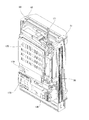
次に、図1〜図4を参照して、遊技機1の構成について具体的に説明する。図1は本発明の遊技機1の正面図であり、図2は遊技盤2の正面図であり、図3は本発明のガラス枠を開放させた状態の遊技機1の斜視図であり、図4は1つの遊技機1の裏面側の斜視図である。
(Composition of gaming machine)
Next, the configuration of the gaming machine 1 will be specifically described with reference to FIGS. FIG. 1 is a front view of a gaming machine 1 according to the present invention, FIG. 2 is a front view of a
遊技機1は、遊技球200が流下する遊技領域6が形成された遊技盤2を設けており、遊技盤2の遊技領域6の前面側には、ガラス枠50が備えられている。このガラス枠50には遊技領域6に向けて遊技球を発射させるための操作ハンドル3が回動可能に設けられている。
The gaming machine 1 is provided with a
また、遊技機1は、複数の遊技球200を貯留する受け皿40が設けられている(図3参照)。この受け皿40は、遊技球200が流下するように操作ハンドル3側に向けて下りの傾斜を有しており、下りの傾斜の端部には、遊技球を受け入れる開口部が設けられている。この開口部に受け入れられた遊技球は、玉送りソレノイド4bが駆動することにより、ガラス枠50の裏面に設けられた玉送り開口部41へ1個ずつ送り出される。そして、玉送り開口部41へ送り出された遊技球は、打出部材4cの方向に向けて下り傾斜を有している発射レール42により、発射レール42の下り傾斜の端部に誘導されることになる。発射レール42の下り傾斜の端部の上方には、遊技球を停止するストッパー43が設けられており、玉送り開口部41から送り出された遊技球200は、発射レール42の下り傾斜の端部で1個の遊技球が停留されることになる(図3、図5参照)。
In addition, the gaming machine 1 is provided with a
そして、発射制御基板160がロータリーソレノイドからなる発射用ソレノイド4aを通電すると、発射用ソレノイド4aに直結された打出部材4cが回転し、打出部材4cにより発射レール42の下り傾斜の端部に貯留されている遊技球200が打ち出され、遊技球が発射される。発射装置の動作原理については、図5を用いて詳しく後述する。
When the
また、操作ハンドル3の右上側には、遊技者が押圧操作可能な右打ちボタン9が備えられている。この右打ちボタン9には、右打ち検出スイッチ9aが設けられており、この右打ち検出スイッチ9aが、所定条件の下で遊技者の操作を検出すると、遊技球の発射強度が変更されることとなる。詳しくは、図10を用いて後述する。
本実施形態では、右打ちボタン9が変更操作部を構成し、右打ち検出スイッチ9aが可変操作部検出手段を構成する。
Further, a right-
In the present embodiment, the right-
上記のようにして発射された遊技球は、発射レール42からレール5a、5b間を上昇して玉戻り防止片5cを超えると、遊技領域6に到達し、その後遊技領域6内を落下する。このとき、遊技領域6に設けられた複数の釘や風車によって、遊技球は予測不能に落下することとなる。
When the game ball fired as described above rises between the
ここで、図2に示すように、遊技領域6は、操作ハンドル3の回動角度が小さく、弱い力で打ち出された遊技球が流下する左側の第1の遊技領域6Lと、操作ハンドル3の回動角度が大きく、強い力で打ち出された遊技球が流下する右側の第2の遊技領域6Rから構成されている。なお、第1の遊技領域6Lと第2の遊技領域6Rとは、釘や後述する飾り部材7によって区分けされているものの、必ずしも全てが区分けされるものではなく、第1の遊技領域6Lと第2の遊技領域6Rとは一部重複しているものである。すなわち、第1の遊技領域6Lは、第1の遊技領域6Lのみからなる第1の専用領域と、第2の遊技領域6Rと重複する共通領域とから構成され、第2の遊技領域6Rも、第2の遊技領域6Rのみからなる第2の専用領域と、上記共通領域とから構成されていることとなる。
Here, as shown in FIG. 2, the
また、上記第1の遊技領域6Lと第2の遊技領域6Rとには、複数の一般入賞口12が設けられている。これら各一般入賞口12には、一般入賞口検出スイッチ12aが設けられており、この一般入賞口検出スイッチ12aが遊技球の入賞を検出すると、所定の賞球(例えば10個の遊技球)が払い出される。
The
また、第1の遊技領域6Lと第2の遊技領域6Rとが重複する共通領域には、遊技球が入球可能な第1始動口14、第2始動口15および第2大入賞口17が設けられている。
Also, in the common area where the
この第2始動口15は、一対の可動片15bを有しており、これら一対の可動片15bが閉状態に維持される第1の態様と、一対の可動片15bが開状態となる第2の態様とに可動制御される。なお、第2始動口15が上記第1の態様に制御されているときには、当該第2始動口15の真上に位置する第2大入賞口17の入賞部材が障害物となって、遊技球の受入れを不可能としている。一方で、第2始動口15が上記第2の態様に制御されているときには、上記一対の可動片15bが受け皿として機能し、特別入賞口28への遊技球の入賞が容易となる。つまり、第2始動口15は、第1の態様にあるときには遊技球の入賞機会がなく、第2の態様にあるときには遊技球の入賞機会が増すこととなる。
The
ここで、第1始動口14には遊技球の入球を検出する第1始動口検出スイッチ14aが設けられ、第2始動口15には遊技球の入球を検出する第2始動口検出スイッチ15aが設けられている。そして、第1始動口検出スイッチ14aまたは第2始動口検出スイッチ15aが遊技球の入球を検出すると、後述する大当たり遊技を実行する権利獲得の抽選(以下、「大当たりの抽選」という)が行われる。また、第1始動口検出スイッチ14aまたは第2始動口検出スイッチ15aが遊技球の入球を検出した場合にも、所定の賞球(例えば3個の遊技球)が払い出される。
Here, the
また、第2大入賞口17は、遊技盤2に形成された開口部から構成されている。この第2大入賞口17の下部には、遊技盤面側からガラス板52側に立設可能な第2大入賞口開閉扉17bを有しており、この2大入賞口開閉扉17bが遊技盤面に立設する開放状態と、遊技盤面に埋没する閉鎖状態とに可動制御される。そして、2大入賞口開閉扉17bが遊技盤面に立設していると、遊技球を第2大入賞口17内に導く受け皿として機能し、遊技球が第2大入賞口17に入球可能となる。この第2大入賞口17には第2大入賞口検出スイッチ17aが設けられており、この第2大入賞口検出スイッチ17aが遊技球の入球を検出すると、予め設定された賞球(例えば15個の遊技球)が払い出される。
In addition, the second grand
さらに、上記第2の遊技領域6Rのみからなる第2の専用領域には、遊技球が通過可能な普通図柄ゲート13と、遊技球が入球可能な第1大入賞口16とが設けられている。
このため、操作ハンドル3を大きく回動させ、強い力で打ち出された遊技球でないと、普通図柄ゲート13と第1大入賞口16とには遊技球が、通過または入賞しないように構成されている。特に、後述する時短遊技状態に移行したとしても、第1の遊技領域6Lに遊技球を流下させてしまうと、普通図柄ゲート13に遊技球が通過しないことから、第2始動口15にある一対の可動片15bが開状態とならず、第2始動口15に遊技球が入賞することが困難になるように構成されている。
Further, the second dedicated area consisting only of the
For this reason, if the
この普通図柄ゲート13には、遊技球の通過を検出するゲート検出スイッチ13aが設けられており、このゲート検出スイッチ13aが遊技球の通過を検出すると、後述する「普通図柄の抽選」が行われる。
The
第1大入賞口16は、通常は大入賞口開閉扉16bによって閉状態に維持されており、遊技球の入球を不可能としている。これに対して、後述する特別遊技が開始されると、第1大入賞口開閉扉16bが開放されるとともに、この第1大入賞口開閉扉16bが遊技球を第1大入賞口16内に導く受け皿として機能し、遊技球が第1大入賞口16に入球可能となる。第1大入賞口16には第1大入賞口検出スイッチ16aが設けられており、この第1大入賞口検出スイッチ16aが遊技球の入球を検出すると、予め設定された賞球(例えば15個の遊技球)が払い出される。
The first big winning
さらには、遊技領域6の最下部であって第1の遊技領域6Lと第2の遊技領域6Rとが重複する共通領域には、一般入賞口12、第1始動口14、第2始動口15、第1大入賞口16および第2大入賞口17のいずれにも入球しなかった遊技球を排出するためのアウト口11が設けられている。
Furthermore, in the lowermost part of the
また、上記遊技盤2の中央位置には、遊技球の流下に影響を与える飾り部材7が設けられている。この飾り部材7の略中央部分には、液晶表示器(LCD)等からなる演出表示装置31が設けられており、この演出表示装置31の上方には、ベルトの形をした演出用駆動装置33が設けられている。なお、本実施形態においては、演出表示装置31を液晶表示器として用いているが、円環状の構造物からなるリールや、いわゆる7セグメントLED、ドットマトリクス等の表示装置を用いてもよい。
A
この演出表示装置31は、遊技が行われていない待機中に画像を表示したり、遊技の進行に応じた画像を表示したりする。なかでも、後述する大当りの抽選結果を報知するための3個の演出図柄36が表示され、特定の演出図柄36の組合せ(例えば、777等)が停止表示されることにより、大当りの抽選結果として大当りが報知される。
より具体的には、第1始動口14または第2始動口15に遊技球が入球したときには、3個の演出図柄36をそれぞれスクロール表示するとともに、所定時間経過後に当該スクロールを停止させて、演出図柄36を停止表示するものである。また、この演出図柄36の変動表示中に、さまざまな画像やキャラクタ等を表示することによって、大当たりに当選するかもしれないという高い期待感を遊技者に与えるようにもしている。
The
More specifically, when a game ball enters the
上記演出用駆動装置33は、その動作態様によって遊技者に期待感を与えるものである。演出用駆動装置33は、例えば、ベルトが下方に移動したり、ベルト中央部の回転部材が回転したりする動作を行う。これら演出用駆動装置33の動作態様によって、遊技者にさまざまな期待感を与えるようにしている。
The
さらに、遊技盤2の上部位置および下部位置の双方には、演出用照明装置34が設けられており、演出用照明装置34は、それぞれ複数のランプ34aを備えており、各ランプ34aの光の照射方向や発光色を変更しながら、さまざまな演出を行うようにしている。
Furthermore, an
また、上記操作ハンドル3の左側には、遊技者が押圧操作可能な演出ボタン35が設けられている。この演出ボタン35は、例えば、上記演出表示装置31に当該演出ボタン35を操作するようなメッセージが表示されたときのみ有効となる。演出ボタン35には、演出ボタン検出スイッチ35aが設けられており、この演出ボタン検出スイッチ35aが遊技者の操作を検出すると、この操作に応じてさらなる演出が実行される。
On the left side of the
さらに、遊技機1の左右上方にはスピーカからなる音声出力装置32が設けられており、上記の各種の演出装置に加えて、音声による演出も行うようにしている。
Furthermore, an
そして、遊技領域6の右下方には、第1特別図柄表示装置20、第2特別図柄表示装置21、普通図柄表示装置22、第1特別図柄保留表示器23、第2特別図柄保留表示器24、普通図柄保留表示器25が設けられている。
In the lower right portion of the
上記第1特別図柄表示装置20は、第1始動口14に遊技球が入球したことを契機として行われた大当たりの抽選結果を報知するものであり、7セグメントのLEDで構成されている。つまり、大当たりの抽選結果に対応する特別図柄が複数設けられており、この第1特別図柄表示装置20に大当たりの抽選結果に対応する特別図柄を表示することによって、抽選結果を遊技者に報知するようにしている。例えば、大当たりに当選した場合には「7」が表示され、ハズレであった場合には「−」が表示される。このようにして表示される「7」や「−」が特別図柄となるが、この特別図柄はすぐに表示されるわけではなく、所定時間変動表示された後に、停止表示されるようにしている。
The first special
ここで、「大当たりの抽選」とは、第1始動口14に遊技球が入球したときに、特別図柄判定用乱数値を取得し、取得した特別図柄判定用乱数値が大当たりのものであるかどうかの判定する処理をいう。この大当たりの抽選結果は即座に遊技者に報知されるわけではなく、第1特別図柄表示装置20において特別図柄が点滅等の変動表示を行い、所定の変動時間を経過したところで、大当たりの抽選結果に対応する特別図柄が停止表示して、遊技者に抽選結果が報知されるようにしている。なお、第2特別図柄表示装置21は、第2始動口15に遊技球が入球したことを契機として行われた大当たりの抽選結果を報知するためのもので、その表示態様は、上記第1特別図柄表示装置20における特別図柄の表示態様と同一である。
Here, the “big winning lottery” is a special symbol determination random number value obtained when a game ball enters the
また、本実施形態において「大当たり」というのは、第1始動口14または第2始動口15に遊技球が入球したことを条件として行われる大当たりの抽選において、大当たり遊技を実行する権利を獲得したことをいう。「大当たり遊技」においては、第1大入賞口16または第2大入賞口17が開放されるラウンド遊技を計15回行う。各ラウンド遊技における第1大入賞口16または第2大入賞口17の総開放時間は最大29.5秒に設定されており、この間に第1大入賞口16または第2大入賞口17に所定個数の遊技球(例えば9個)が入球すると、1回のラウンド遊技が終了となる。つまり、「大当たり遊技」は、第1大入賞口16または第2大入賞口17に遊技球が入球するとともに、当該入球に応じた賞球を遊技者が獲得できることから、多量の賞球を獲得可能な遊技である。
Further, in this embodiment, “big hit” means that a right to win a big hit game is obtained in a big win lottery performed on condition that a game ball has entered the
また、普通図柄表示装置22は、普通図柄ゲート13を遊技球が通過したことを契機として行われる普通図柄の抽選結果を報知するためのものである。詳しくは後述するが、この普通図柄の抽選によって当たりに当選すると普通図柄表示装置22が点灯し、その後、上記第2始動口15が所定時間、第2の態様に制御される。
The normal
ここで、「普通図柄の抽選」とは、普通図柄ゲート13に遊技球が通過したときに、普通図柄判定用乱数値を取得し、取得した普通図柄判定用乱数値が「当たり」のものであるかどうかの判定する処理をいう。この普通図柄の抽選結果についても、普通図柄ゲート13を遊技球が通過して即座に抽選結果が報知されるわけではなく、普通図柄表示装置22において普通図柄が点滅等の変動表示を行い、所定の変動時間を経過したところで、普通図柄の抽選結果に対応する普通図柄が停止表示して、遊技者に抽選結果が報知されるようにしている。
Here, “ordinary symbol lottery” means that when a game ball passes through the
さらに、特別図柄の変動表示中や後述する特別遊技中等、第1始動口14または第2始動口15に遊技球が入球して、即座に大当たりの抽選が行えない場合には、一定の条件のもとで、大当たりの抽選の権利が保留される。より詳細には、第1始動口14に遊技球が入球したときに取得された特別図柄判定用乱数値を第1保留として記憶し、第2始動口15に遊技球が入球したときに取得された特別図柄判定用乱数値を第2保留として記憶する。
これら両保留は、それぞれ上限保留個数を4個に設定し、その保留個数は、それぞれ第1特別図柄保留表示器23と第2特別図柄保留表示器24とに表示される。なお、第1保留が1つの場合には、第1特別図柄保留表示器23の左側のLEDが点灯し、第1保留が2つの場合には、第1特別図柄保留表示器23の2つのLEDが点灯する。また、第1保留が3つの場合には、第1特別図柄保留表示器23の左側のLEDが点滅するとともに右側のLEDが点灯し、第1保留が4つの場合には、第1特別図柄保留表示器23の2つのLEDが点滅する。また、第2特別図柄保留表示器24においても、上記と同様に第2保留の保留個数が表示される。
そして、普通図柄の上限保留個数も4個に設定されており、その保留個数が、上記第1特別図柄保留表示器23および第2特別図柄保留表示器24と同様の態様によって、普通図柄保留表示器25において表示される。
Furthermore, if a game ball enters the
For both of these holds, the upper limit hold number is set to 4, and the hold number is displayed on the first special symbol hold
The upper limit reserved number of normal symbols is also set to four, and the reserved number of normal symbols is displayed in the same manner as the first special symbol hold
ガラス枠50は、遊技盤2の前方(遊技者側)において遊技領域6を視認可能に覆うガラス板52を支持している。なお、ガラス板52は、ガラス枠50に対して着脱可能に固定されている。
The
またガラス枠50は、左右方向の一端側(たとえば遊技機1に正対して左側)においてヒンジ機構部51を介して外枠60に連結されており、ヒンジ機構部51を支点として左右方向の他端側(たとえば遊技機1に正対して右側)を外枠60から開放させる方向に回動可能とされている。ガラス枠50は、ガラス板52とともに遊技盤2を覆い、ヒンジ機構部51を支点として扉のように回動することによって、遊技盤2を含む外枠60の内側部分を開放することができる。ガラス枠50の他端側には、ガラス枠50の他端側を外枠60に固定するロック機構が設けられている。ロック機構による固定は、専用の鍵によって解除することが可能とされている。また、ガラス枠50には、ガラス枠50が外枠60から開放されているか否かを検出する扉開放スイッチ133も設けられている。
The
遊技機1の裏面には、主制御基板110、演出制御基板120、払出制御基板130、電源基板170、遊技情報出力端子板30などが設けられている。また、電源基板170に遊技機1に電力を給電するための電源プラグ171や、図示しない電源スイッチが設けられている。
On the back side of the gaming machine 1, a
(発射装置の動作原理図)
図5を参照して、発射装置の動作原理について具体的に説明する。
(Operation principle diagram of launcher)
With reference to FIG. 5, the operation principle of the launching device will be specifically described.
発射装置は、発射レール42の下り傾斜の端部側に設けられており、ロータリーソレノイドからなる発射用ソレノイド4aと発射制御基板160とを含んで構成されている。また、発射用ソレノイド4aには打出部材4cが直結されており、この打出部材4cは、遊技球を打ち出す槌4dと磁力を帯びた第1マグネット部4eとに二股状に分かれている。さらに、発射レール42の下り傾斜の端部の上側には、遊技球を停止するストッパー43と第1マグネット部4eとは異なる磁極からなる磁力を帯びた第2マグネット部44とが設けられている。
The launching device is provided on the end of the launching
遊技者が操作ハンドル3を回転させると、操作ハンドル3の内部に設けられているタッチセンサ3a(図6参照)が操作ハンドル3と遊技者とが接触していることを検知するとともに、操作ハンドル3に直結している可変抵抗器からなる発射ボリューム3bも回転する。
When the player rotates the
発射制御基板160は、タッチセンサ3aからのタッチ信号と、発射ボリューム3bに応じた電圧値とを少なくとも入力し、入力した電圧値に基づいて電流値を生成し、生成した電流値で発射用ソレノイド4aを通電する。なお、発射制御基板160は、少なくともタッチ信号が入力されないと、発射用ソレノイド4aを通電しないように構成されている。
The firing
図5(a)に示すように、発射制御基板160によって発射用ソレノイド4aが通電されると、発射用ソレノイド4aに直結された打出部材4cが回転し、打出部材4cの槌4dにより遊技球が打ち出され、遊技領域6に向けて遊技球が発射される。
As shown in FIG. 5A, when the firing
図5(b)に示すように、発射制御基板160によって発射用ソレノイド4aが通電されなくなると、槌4dの自重に加え、第1マグネット部4eと第2マグネット部44と引き合う磁力により、打出部材4cが元の位置に戻ることになる。
As shown in FIG. 5B, when the firing
このように、発射制御基板160が発射用ソレノイド4aを通電することで、遊技球が発射されることになる。
本実施形態では、操作ハンドル3が発射操作部を構成し、発射ボリューム3bが操作量検出手段を構成する。また、打出部材4cと直結した発射用ソレノイド4aおよび発射制御基板160が発射駆動装置を構成する。
Thus, the
In the present embodiment, the operation handle 3 constitutes a firing operation unit, and the
(制御手段の内部構成)
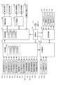
次に、図6の遊技機1全体のブロック図を用いて、遊技の進行を制御する制御手段について説明する。
(Internal structure of control means)
Next, control means for controlling the progress of the game will be described using the block diagram of the entire gaming machine 1 in FIG.
主制御基板110は遊技の基本動作を制御する主制御手段であり、第1始動口検出スイッチ14a等の各種検出信号を入力して、第1特別図柄表示装置20や第1大入賞口開閉ソレノイド16c等を駆動させて遊技を制御するものである。
The
この主制御基板110は、メインCPU110a、メインROM110bおよびメインRAM110cから構成されるワンチップマイコン110mと、主制御用の入力ポートと出力ポート(図示せず)と少なくとも備えている。
The
この主制御用の入力ポートには、払出制御基板130、一般入賞口12に遊技球が入球したことを検知する一般入賞口検出スイッチ12a、普通図柄ゲート13に遊技球が入球したことを検知するゲート検出スイッチ13a、第1始動口14に遊技球が入球したことを検知する第1始動口検出スイッチ14a、第2始動口15に遊技球が入球したことを検知する第2始動口検出スイッチ15a、第1大入賞口16に遊技球が入球したことを検知する第1大入賞口検出スイッチ16a、第2大入賞口17に遊技球が入球したことを検知する第2大入賞口検出スイッチ17aが接続されている。この主制御用の入力ポートによって、各種信号が主制御基板110に入力される。
The main control input port includes a
また、主制御用の出力ポートには、払出制御基板130、第2始動口15の一対の可動片15bを開閉動作させる始動口開閉ソレノイド15c、第1大入賞口開閉扉16bを動作させる第1大入賞口開閉ソレノイド16c、第2大入賞口開閉扉17bを動作させる第2大入賞口開閉ソレノイド17c、特別図柄を表示する第1特別図柄表示装置20と第2特別図柄表示装置21、普通図柄を表示する普通図柄表示装置22、特別図柄の保留球数を表示する第1特別図柄保留表示器23と第2特別図柄保留表示器24、特別図柄の保留球数を表示する普通図柄保留表示器25、外部情報信号を出力する遊技情報出力端子板30が接続されている。この主制御用の出力ポートによって、各種信号が出力される。
特に、本実施形態では、第1大入賞口16が開放する大当り(いわゆる右打ち大当り)および時短遊技状態のときには、主制御用の出力ポートから払出制御基板130に向けて右打ち状態信号が出力されることになる。
The main control output port includes a
In particular, in the present embodiment, a right-handed state signal is output from the main control output port toward the
メインCPU110aは、各検出スイッチやタイマからの入力信号に基づいて、メインROM110bに格納されたプログラムを読み出して演算処理を行うとともに、各装置や表示器を直接制御したり、あるいは演算処理の結果に応じて他の基板にコマンドを送信したりする。
The
主制御基板110のメインROM110bには、遊技制御用のプログラムや各種の遊技に決定に必要なデータ、テーブルが記憶されている。
例えば、大当たり抽選に参照される大当り判定テーブル、普通図柄の抽選に参照される当り判定テーブル、特別図柄の停止図柄を決定する図柄決定テーブル等がメインROM110bに記憶されている。
なお、上述したテーブルは、本実施形態におけるテーブルのうち、特徴的なテーブルを一例として列挙しているに過ぎず、遊技の進行にあたっては、この他にも不図示のテーブルやプログラムが多数設けられている。
The
For example, the
Note that the above-described table is merely an example of characteristic tables among the tables in the present embodiment, and a number of other tables and programs (not shown) are provided for the progress of the game. ing.
主制御基板110のメインRAM110cは、メインCPU110aの演算処理時におけるデータのワークエリアとして機能し、複数の記憶領域を有している。
例えば、メインRAM110cには、普通図柄保留数(G)記憶領域、普通図柄保留記憶領域、第1特別図柄保留数(U1)記憶領域、第2特別図柄保留数(U2)記憶領域、判定記憶領域、第1特別図柄記憶領域、第2特別図柄記憶領域、ラウンド遊技回数(R)記憶領域、開放回数(K)記憶領域、大入賞口入球数(C)記憶領域、遊技状態記憶領域、遊技状態バッファ、停止図柄データ記憶領域、演出用伝送データ格納領域、各種のタイマカウンタが設けられている。なお、上述した記憶領域も一例に過ぎず、この他にも多数の記憶領域が設けられている。
The
For example, the
遊技情報出力端子板30は、主制御基板110において生成された外部情報信号を遊技店のホールコンピュータ等に出力するための基板である。遊技情報出力端子板30は、主制御基板110と配線接続され、外部情報を遊技店のホールコンピュータ等と接続をするためのコネクタが設けられている。
The game information
電源基板170は、コンデンサからなるバックアップ電源を備えており、遊技機1に電源電圧を供給するとともに、遊技機1に供給する電源電圧を監視し、電源電圧が所定値以下となったときに、電断検知信号を主制御基板110に出力する。より具体的には、電断検知信号がハイレベルになるとメインCPU110aは動作可能状態になり、電断検知信号がローレベルになるとメインCPU110aは動作停止状態になる。バックアップ電源はコンデンサに限らず、例えば、電池でもよく、コンデンサと電池とを併用して用いてもよい。
The
演出制御基板120は、主に遊技中や待機中等の各演出を制御する。この演出制御基板120は、サブCPU120a、サブROM120b、サブRAM120cを備えており、主制御基板110に対して、当該主制御基板110から演出制御基板120への一方向に通信可能に接続されている。サブCPU120aは、主制御基板110から送信されたコマンド、または、上記演出ボタン検出スイッチ35a、タイマからの入力信号に基づいて、サブROM120bに格納されたプログラムを読み出して演算処理を行うとともに、当該処理に基づいて、対応するデータをランプ制御基板140または画像制御基板150に送信する。サブRAM120cは、サブCPU120aの演算処理時におけるデータのワークエリアとして機能する。
The
例えば、演出制御基板120におけるサブCPU120aは、主制御基板110から特別図柄の変動態様を示す変動パターン指定コマンドを受信すると、受信した変動パターン指定コマンドの内容を解析して、演出表示装置31、音声出力装置32、演出用駆動装置33、演出用照明装置34に所定の演出を実行させるためのデータを生成し、かかるデータを画像制御基板150やランプ制御基板140へ送信する。
For example, when the
演出制御基板120のサブROM120bには、演出制御用のプログラムや各種の遊技の決定に必要なデータ、テーブルが記憶されている。
例えば、主制御基板から受信した変動パターン指定コマンドに基づいて演出パターンを決定するための演出パターン決定テーブル、停止表示する演出図柄36の組み合わせを決定するための演出図柄決定テーブル等がサブROM120bに記憶されている。なお、上述したテーブルは、本実施形態におけるテーブルのうち、特徴的なテーブルを一例として列挙しているに過ぎず、遊技の進行にあたっては、この他にも不図示のテーブルやプログラムが多数設けられている。
The
For example, an effect pattern determination table for determining an effect pattern based on a variation pattern designation command received from the main control board, an effect symbol determination table for determining a combination of
演出制御基板120のサブRAM120cは、複数の記憶領域を有している。
サブRAM120cには、コマンド受信バッファ、遊技状態記憶領域、演出モード記憶領域、演出パターン記憶領域、演出図柄記憶領域等が設けられている。なお、上述した記憶領域も一例に過ぎず、この他にも多数の記憶領域が設けられている。
The
The
払出制御基板130は、遊技球の発射制御と賞球の払い出し制御を行う。この払出制御基板130は、図示しない払出CPU、払出ROM、払出RAMから構成されるワンチップマイコンを備えており、主制御基板110に対して、双方向に通信可能に接続されている。払出CPUは、遊技球が払い出されたか否かを検知する払出球計数検知スイッチ132、扉開放スイッチ133、タイマからの入力信号に基づいて、払出ROMに格納されたプログラムを読み出して演算処理を行うとともに、当該処理に基づいて、対応するデータを主制御基板110に送信する。また、払出制御基板130の出力側には、遊技球の貯留部から所定数の賞球を遊技者に払い出すための賞球払出装置の払出モータ131が接続されている。払出CPUは、主制御基板110から送信された払出個数指定コマンドに基づいて、払出ROMから所定のプログラムを読み出して演算処理を行うとともに、賞球払出装置の払出モータ131を制御して所定の賞球を遊技者に払い出す。このとき、払出RAMは、払出CPUの演算処理時におけるデータのワークエリアとして機能する。
さらに、主制御基板110から出力された右打ち状態信号を入力すると、払出CPUはその右打ち状態信号を発射制御基板160に向けて出力する。すなわち、主制御基板110から出力された右打ち状態信号は、払出制御基板130を介して、発射制御基板160に入力されることとなる。
The
Further, when the right-handed state signal output from the
ランプ制御基板140は、遊技盤2に設けられた演出用照明装置34を点灯制御したり、光の照射方向を変更するためのモータに対する駆動制御をしたりする。また、演出用駆動装置33を動作させるソレノイドやモータ等の駆動源を通電制御する。このランプ制御基板140は、演出制御基板120に接続されており、演出制御基板120から送信されたデータに基づいて、上記の各制御を行うこととなる。
The
画像制御基板150は、上記演出表示装置31の画像表示制御を行うための図示しない画像CPU、画像ROM、画像RAM、VRAMと、音声CPU、音声ROM、音声RAMとを備えている。この画像制御基板150は、上記演出制御基板120に双方向通信可能に接続されており、その出力側に上記演出表示装置31および音声出力装置32を接続している。
The
上記画像ROMには、演出表示装置31に表示される演出図柄36や背景等の画像データが多数格納されており、画像CPUが演出制御基板120から送信されたコマンドに基づいて所定のプログラムを読み出すとともに、所定の画像データを画像ROMからVRAMに読み出して、演出表示装置31における表示制御をする。なお、画像CPUは、演出表示装置31に対して、背景画像表示処理、演出図柄表示処理、キャラクタ画像表示処理など各種画像処理を実行するが、背景画像、演出図柄画像、キャラクタ画像は、演出表示装置31の表示画面上において重畳表示される。
すなわち、演出図柄画像やキャラクタ画像は背景画像よりも手前に見えるように表示される。このとき、同一位置に背景画像と図柄画像が重なる場合、Zバッファ法など周知の陰面消去法により各画像データのZバッファのZ値を参照することで、図柄画像を優先してVRAMに記憶させる。
The image ROM stores a large number of image data such as
That is, the effect design image and the character image are displayed so as to be seen in front of the background image. At this time, if the background image and the design image overlap at the same position, the design image is preferentially stored in the VRAM by referring to the Z value of the Z buffer of each image data by a known hidden surface removal method such as the Z buffer method. .
また、上記音声ROMには、音声出力装置32から出力される音声のデータが多数格納されており、音声CPUは、演出制御基板120から送信されたコマンドに基づいて所定のプログラムを読み出すとともに、音声出力装置32における音声出力制御をする。
The audio ROM stores a large amount of audio data output from the
発射制御基板160は、タッチセンサ3aからのタッチ信号および右打ち検出スイッチ9aからの右打ち検出信号を入力するとともに、発射ボリューム3bからの電圧値を読み出し、発射用ソレノイド4aや玉送りソレノイド4bを駆動させる制御を行う。具体的には、図10を用いて後述する。
The firing
(遊技状態の説明)
次に、遊技が進行する際の遊技状態について説明する。本実施形態においては、「低確率遊技状態」「高確率遊技状態」「時短遊技状態」「非時短遊技状態」のいずれかの遊技状態にて遊技が進行する。ただし、遊技の進行中において、遊技状態が「低確率遊技状態」または「高確率遊技状態」である場合には、必ず「時短遊技状態」または「非時短遊技状態」となっている。つまり、(1)「低確率遊技状態」であって「時短遊技状態」である場合と、(2)「低確率遊技状態」であって「非時短遊技状態」である場合と、(3)「高確率遊技状態」であって「時短遊技状態」である場合と、(4)「高確率遊技状態」であって「非時短遊技状態」である場合とが存在することとなる。
なお、遊技を開始したときの遊技状態、すなわち遊技機1の初期の遊技状態は、「低確率遊技状態」であって「非時短遊技状態」に設定されており、この遊技状態を本実施形態においては「通常遊技状態」と称することとする。
(Description of gaming state)
Next, the gaming state when the game progresses will be described. In the present embodiment, the game progresses in any one of the “low probability gaming state”, “high probability gaming state”, “time / short gaming state”, and “non-time / short gaming state”. However, while the game is in progress, if the game state is “low probability game state” or “high probability game state”, it is always “time-short game state” or “non-time-short game state”. That is, (1) “low probability gaming state” and “short-time gaming state”, (2) “low probability gaming state” and “non-short-time gaming state”, and (3) There are a case of “high probability gaming state” and “time-short gaming state” and a case of (4) “high probability gaming state” and “non-time-short gaming state”.
Note that the gaming state when the game is started, that is, the initial gaming state of the gaming machine 1 is a “low probability gaming state” and is set to a “non-short-time gaming state”. Is referred to as a “normal gaming state”.
本実施形態において「低確率遊技状態」というのは、第1始動口14または第2始動口15に遊技球が入球したことを条件として行われる大当たりの抽選において、大当たりの当選確率が1/299.5に設定された遊技状態をいう。これに対して「高確率遊技状態」というのは、上記大当たりの当選確率が1/29.95に設定された遊技状態をいう。したがって、「高確率遊技状態」では、「低確率遊技状態」よりも、大当たりに当選しやすいこととなる。
なお、低確率遊技状態から高確率遊技状態に変更するのは、後述する大当たり遊技を終了した後である。
In the present embodiment, the “low probability gaming state” means that in the jackpot lottery performed on the condition that a game ball has entered the
Note that the low probability gaming state is changed to the high probability gaming state after the jackpot game described later is finished.
本実施形態において「非時短遊技状態」というのは、普通図柄ゲート13を遊技球が通過したことを条件として行われる普通図柄の抽選において、その抽選結果に対応する普通図柄の変動時間が29秒と長く設定され、かつ、当たりに当選した際の第2始動口15の開放制御時間が0.2秒と短く設定された遊技状態をいう。つまり、普通図柄ゲート13を遊技球が通過すると、普通図柄の抽選が行われて、普通図柄表示装置22において普通図柄の変動表示が行われるが、普通図柄は変動表示が開始されてから29秒後に停止表示する。そして、抽選結果が当たりであった場合には、普通図柄の停止表示後に、第2始動口15が約0.2秒間、第2の態様に制御される。
In the present embodiment, the “non-short game state” means that, in the normal symbol lottery performed on the condition that the game ball has passed through the
これに対して「時短遊技状態」というのは、普通図柄ゲート13を遊技球が通過したことを条件として行われる普通図柄の抽選において、その抽選結果に対応する普通図柄の変動時間が3秒と、「非時短遊技状態」よりも短く設定され、かつ、当たりに当選した際の第2始動口15の開放制御時間が3.5秒と、「非時短遊技状態」よりも長く設定された遊技状態をいう。さらに、「非時短遊技状態」においては普通図柄の抽選において当たりに当選する確率が1/11に設定され、「時短遊技状態」においては普通図柄の抽選において当たりに当選する確率が10/11に設定される。
したがって、「時短遊技状態」においては、「非時短遊技状態」よりも、普通図柄ゲート13を遊技球が通過する限りにおいて、第2始動口15が第2の態様に制御されやすくなる。これにより、「時短遊技状態」では、遊技者が遊技球を消費せずに遊技を進行することが可能となる。
また、普通図柄ゲート13が第2の遊技領域6Rのみからなる第2の専用領域に設けられていることから、「時短遊技状態」のときには、操作ハンドル3を大きく回動させ、強い発射強度で遊技球を発射して遊技を行うように構成されている。
なお、普通図柄の抽選において当たりに当選する確率を「非時短遊技状態」および「時短遊技状態」のいずれの遊技状態であっても変わらないように設定してもよい。
On the other hand, the “short-time gaming state” means that the normal symbol variation time corresponding to the lottery result is 3 seconds in the normal symbol lottery performed on condition that the game ball has passed through the
Therefore, in the “short-time gaming state”, the
In addition, since the
Note that the probability of winning in the normal symbol lottery may be set so that it does not change in any of the “non-short-time gaming state” and the “time-short gaming state”.
(大当たりの種類の説明)
本実施形態においては、第1大入賞口16を開放させる「第1の大当たり」と、第2大入賞口17を開放させる「第2の大当たり」との2種類の「大当たり」が設けられている。
(Description of jackpot type)
In the present embodiment, there are provided two types of “big jackpots”: “first jackpot” that opens the
本実施形態において「第1の大当たり」というのは、第1始動口14または第2始動口15に遊技球が入球したことを条件として行われる大当たりの抽選において、大当りに当選し、第1の大当たり図柄が決定されたときに実行される遊技をいう。
「第1の大当たり」においては、第1大入賞口16が開放されるラウンド遊技を計15回行う。各ラウンド遊技における第1大入賞口16の総開放時間は最大29秒に設定されており、この間に第1大入賞口16に所定個数の遊技球(例えば9個)が入球すると、1回のラウンド遊技が終了となる。つまり、「第1の大当たり」は、第1大入賞口16に遊技球が入球するとともに、当該入球に応じた賞球を遊技者が獲得できることから、多量の賞球を獲得可能な遊技である。また、第1大入賞口16は、第2の遊技領域6Rのみからなる第2の専用領域に設けられていることから、第1の大当たりのときには、操作ハンドル3を大きく回動させ、強い発射強度で遊技球を発射して遊技を行うように構成されている。
In the present embodiment, the “first jackpot” means that in the jackpot lottery performed on the condition that a game ball has entered the
In the “first jackpot”, the round game in which the first big winning
本実施形態において「第2の大当たり」というのは、第1始動口14または第2始動口15に遊技球が入球したことを条件として行われる大当たりの抽選において、大当りに当選し、第2の大当たり図柄が決定されたときに実行される遊技をいう。
「第2の大当たり」においては、第2大入賞口17が開放されるラウンド遊技を計15回行う。各ラウンド遊技における第2大入賞口17の総開放時間は最大0.052秒に設定されている。この間に第2大入賞口17に所定個数の遊技球(例えば9個)が入球すると、1回のラウンド遊技が終了となるが、上記のとおり第2大入賞口17の開放時間が極めて短いため、遊技球が入球することはほとんどなく、また、遊技球が入球したとしても、1回のラウンド遊技で1個〜2個程度しか遊技球が入球することはない。つまり、「第2の大当たり」は、「第1の大当たり」とは異なり、少量の賞球を獲得可能な遊技である。
In the present embodiment, the “second jackpot” means that in the jackpot lottery performed on the condition that a game ball has entered the
In the “second jackpot”, the round game in which the second grand
次に、遊技機1における遊技の進行について、フローチャートを用いて説明する。 Next, the progress of the game in the gaming machine 1 will be described using a flowchart.
(主制御基板のメイン処理)
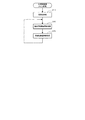
図7を用いて、主制御基板110のメイン処理を説明する。
(Main processing of main control board)
The main process of the
電源基板170により電源が供給されると、メインCPU110aにシステムリセットが発生し、メインCPU110aは、以下のメイン処理を行う。
When power is supplied from the
まず、ステップS10において、メインCPU110aは、初期化処理を行う。この処理において、メインCPU110aは、電源投入に応じて、メインROM110bから起動プログラムを読み込むとともに、メインRAM110cに記憶されるフラグなどを初期化する処理を行う。
First, in step S10, the
ステップS20において、メインCPU110aは、特別図柄の変動態様(変動時間)を決定するための演出用乱数値の更新を行う演出乱数更新処理を行う。
In step S20, the
ステップS30において、メインCPU110aは、特別図柄判定用初期乱数値、大当たり図柄用初期乱数値、普通図柄判定用初期乱数値の更新を行う。以降は、所定の割込み処理が行われるまで、ステップS20とステップS30との処理を繰り返し行う。
In step S30, the
(主制御基板のタイマ割込処理)
図8を用いて、主制御基板110のタイマ割込処理を説明する。
(Timer interrupt processing of main control board)
The timer interrupt process of the
主制御基板110に設けられたリセット用クロックパルス発生回路によって、所定の周期(4ミリ秒)毎にクロックパルスが発生されることで、以下に述べるタイマ割込処理が実行される。
A clock pulse is generated every predetermined period (4 milliseconds) by the reset clock pulse generation circuit provided on the
まず、ステップS100において、メインCPU110aは、メインCPU110aのレジスタに格納されている情報をスタック領域に退避させる。
First, in step S100, the
ステップS110において、メインCPU110aは、特別図柄時間カウンタの更新処理、特別電動役物の開放時間等などの特別遊技タイマカウンタの更新処理、普通図柄時間カウンタの更新処理、普電開放時間カウンタの更新処理等の各種タイマカウンタを更新する時間制御処理を行う。具体的には、特別図柄時間カウンタ、特別遊技タイマカウンタ、普通図柄時間カウンタ、普電開放時間カウンタから1を減算する処理を行う。
In step S110, the
ステップS120において、メインCPU110aは、特別図柄判定用乱数値、大当たり図柄用乱数値、普通図柄判定用乱数値の乱数更新処理を行う。
具体的には、それぞれの乱数値及び乱数カウンタを+1加算して更新する。なお、加算した乱数カウンタが乱数範囲の最大値を超えた場合(乱数カウンタが1周した場合)には、乱数カウンタを0に戻し、その時の初期乱数値からそれぞれの乱数値を新たに更新する。
In step S120, the
Specifically, each random number value and random number counter are updated by adding +1. When the added random number counter exceeds the maximum value in the random number range (when the random number counter makes one revolution), the random number counter is returned to 0, and each random number value is newly updated from the initial random number value at that time. .
ステップS130において、メインCPU110aは、ステップS30と同様に、特別図柄判定用初期乱数値、大当たり図柄用初期乱数値、普通図柄判定用初期乱数値を更新する初期乱数値更新処理を行う。
In step S130, as in step S30, the
ステップS200において、メインCPU110aは、入力制御処理を行う。
この処理において、メインCPU110aは、一般入賞口検出スイッチ12a、第1大入賞口検出スイッチ16a、第2大入賞口検出スイッチ17a、第1始動口検出スイッチ14a、第2始動口検出スイッチ15a、ゲート検出スイッチ13aの各スイッチに入力があったか否か判定する入力処理を行う。
In step S200, the
In this process, the
具体的には、一般入賞口検出スイッチ12a、第1大入賞口検出スイッチ16a、第2大入賞口検出スイッチ17a、第1始動口検出スイッチ14a、第2始動口検出スイッチ15aからの各種検出信号を入力した場合には、賞球のために用いる賞球カウンタに、それぞれの入賞口に対応する所定のデータを加算して更新する。
Specifically, various detection signals from the general winning
さらに、第1始動口検出スイッチ14aから検出信号を入力した場合には、第1特別図柄保留数(U1)記憶領域にセットされているデータが4未満であれば、第1特別図柄保留数(U1)記憶領域に1を加算し、特別図柄判定用乱数値、大当たり図柄用乱数値、演出用乱数値を取得して、取得した乱数値を第1特別図柄記憶領域にある所定の記憶部に記憶する。
同様に、第2始動口検出スイッチ15aから検出信号を入力した場合には、第2特別図柄保留数(U2)記憶領域にセットされているデータが4未満であれば、第2特別図柄保留数(U2)記憶領域に1を加算し、特別図柄判定用乱数値、大当たり図柄用乱数値、演出用乱数値を取得して、取得した乱数値を第2特別図柄記憶領域にある所定の記憶部に記憶する。
Furthermore, when a detection signal is input from the first start
Similarly, when a detection signal is input from the second start
また、ゲート検出スイッチ13aから検出信号を入力した場合には、普通図柄保留数(G)記憶領域にセットされているデータが4未満であれば、普通図柄保留数(G)記憶領域に1を加算し、普通図柄判定用乱数値を取得して、取得した普通図柄判定用乱数値を普通図柄保留記憶領域にある所定の記憶部に記憶する。
When a detection signal is input from the
さらに、第1大入賞口検出スイッチ16aまたは第2大入賞口検出スイッチ17aからの検出信号を入力した場合には、第1大入賞口16または第2大入賞口17に入賞した遊技球を計数するための大入賞口入球カウンタ(C)記憶領域のカウンタを加算して更新する。
Further, when a detection signal is input from the first grand prize opening
ステップS300において、メインCPU110aは、大当たりの抽選、特別電動役物、遊技状態の制御を行うための特図特電制御処理を行う。詳しくは、図9を用いて後述する。
In step S300, the
ステップS400において、メインCPU110aは、普通図柄の抽選、普通電動役物の制御を行うための普図普電制御処理を行う。
具体的には、まず普通図柄保留数(G)記憶領域に1以上のデータがセットされているか否かを判定する。
普通図柄保留数(G)記憶領域に1以上のデータがセットされていなければ、今回の普図普電制御処理を終了する。
普通図柄保留数(G)記憶領域に1以上のデータがセットされていれば、普通図柄保留記憶領域に記憶された普通図柄判定用乱数値を参照して普通図柄の抽選を行う。そして、普通図柄表示装置22において普通図柄の変動表示を行って、所定の変動時間が経過すると普通図柄の抽選の結果に対応する普通図柄の停止表示を行う。その後、参照した普通図柄判定用乱数値が「当たり」のものであれば、始動口開閉ソレノイド15cを駆動させ、第2始動口15を所定の開放時間、第2の態様に制御する。
ここで、非時短遊技状態であれば、普通図柄の変動時間を29秒に設定し、「当たり」であると第2始動口15を0.2秒間、第2の態様に制御する。これに対して、時短遊技状態であれば、普通図柄の変動時間を0.2秒に設定し、「当たり」であると第2始動口15を3.5秒間、第2の態様に制御する。
In step S400, the
Specifically, it is first determined whether or not one or more data is set in the normal symbol reservation number (G) storage area.
If one or more data is not set in the normal symbol holding number (G) storage area, the current normal power control process is terminated.
If one or more data is set in the normal symbol hold number (G) storage area, the normal symbol lottery is performed with reference to the normal symbol determination random number value stored in the normal symbol hold storage area. Then, the normal
Here, in the non-short-time gaming state, the variation time of the normal symbol is set to 29 seconds, and if it is “winning”, the
ステップS500において、メインCPU110aは、払出制御処理を行う。
この処理において、メインCPU110aは、一般入賞口12、第1始動口14、第2始動口15、第1大入賞口16、第2大入賞口17に遊技球が入賞したか否かの判定を行い、入賞があった場合には、それぞれの入賞口に対応する払出個数指定コマンドを生成して、生成した払出個数指定コマンドを払出制御基板103に送信する。
In step S500, the
In this process, the
ステップS600において、メインCPU110aは、外部情報データ、始動口開閉ソレノイドデータ、第1大入賞口開閉ソレノイドデータ、第2大入賞口開閉ソレノイドデータ、特別図柄表示装置データ、普通図柄表示装置データ、記憶数指定コマンドのデータ作成処理を行う。
In step S600, the
ステップS700において、メインCPU110aは、出力制御処理を行う。この処理において、上記S600で作成した外部情報データ、始動口開閉ソレノイドデータ、第1大入賞口開閉ソレノイドデータ、第2大入賞口開閉ソレノイドデータの信号を出力させるポート出力処理を行う。
また、第1特別図柄表示装置20、第2特別図柄表示装置21および普通図柄表示装置22の各LEDを点灯させるために、上記S600で作成した特別図柄表示装置データと普通図柄表示装置データとを出力する表示装置出力処理を行う。さらに、メインRAM110cの演出用伝送データ格納領域にセットされているコマンドを送信するコマンド送信処理も行う。
In step S700, the
Further, the special symbol display device data and the normal symbol display device data created in S600 are used to turn on the LEDs of the first special
ステップS800において、メインCPU110aは、ステップS100で退避した情報をメインCPU110aのレジスタに復帰させる。
In step S800, the
図9を用いて、主制御基板110の特図特電制御処理を説明する。
With reference to FIG. 9, the special figure special power control process of the
まず、ステップS301において特図特電処理データの値をロードし、ステップS302においてロードした特図特電処理データから分岐アドレスを参照し、特図特電処理データ=0であれば特別図柄記憶判定処理(ステップS310)に処理を移し、特図特電処理データ=1であれば特別図柄変動処理(ステップS320)に処理を移し、特図特電処理データ=2であれば特別図柄停止処理(ステップS330)に処理を移し、特図特電処理データ=3であれば大当たり遊技処理(ステップS340)に処理を移し、特図特電処理データ=4であれば大当り遊技終了処理(ステップS350)に処理を移す。
この「特図特電処理データ」は、後述するように特図特電制御処理の各サブルーチンの中で必要に応じてセットされていくので、その遊技において必要なサブルーチンが適宜処理されていくことになる。
First, in step S301, the value of the special figure special electricity processing data is loaded, the branch address is referred to from the special figure special electric treatment data loaded in step S302, and if the special figure special electric treatment data = 0, the special symbol memory determination process (step The process proceeds to S310). If the special symbol special power processing data = 1, the process proceeds to the special symbol variation processing (step S320). If the special symbol special power processing data = 2, the special symbol stop processing (step S330) is performed. If the special figure special electric processing data = 3, the processing is transferred to the big hit game processing (step S340), and if the special figure special electric processing data = 4, the processing is transferred to the big hit game end processing (step S350).
This “special drawing special electricity processing data” is set as necessary in each subroutine of the special figure special electricity control processing as will be described later, so that the subroutine necessary for the game is appropriately processed. .
ステップS310の特別図柄記憶判定処理においては、メインCPU110aは、大当たりの抽選、停止表示する特別図柄の決定をする処理を行う。
具体的には、まず第1特別図柄保留数(U1)記憶領域または第2特別図柄保留数(U2)記憶領域に1以上のデータがセットされているか否かを判定する。第1特別図柄保留数(U1)記憶領域または第2特別図柄保留数(U2)記憶領域のいずれの記憶領域にも1以上のデータがセットされていなければ、特図特電処理データ=0を保持したまま、今回の特別図柄変動処理を終了する。
第1特別図柄保留数(U1)記憶領域に1以上のデータがセットされていれば、第1特別図柄記憶領域に記憶された特別図柄判定用乱数値を参照して、第2特別図柄保留数(U2)記憶領域に1以上のデータがセットされていれば、第2特別図柄記憶領域に記憶された特別図柄判定用乱数値を参照して、大当たりの抽選を行う。ここで、高確率遊技状態であれば、大当たりの抽選において、「大当たり」のものと判定される特別図柄判定用乱数値が、低確率遊技状態の場合と比べて多く設定してある。このため、高確率遊技状態では、低確率遊技状態よりも、大当たりに当選しやすいこととなる。なお、第1特別図柄保留数(U1)記憶領域にも第2特別図柄保留数(U2)記憶領域にも1以上のデータがセットされている場合には、第2特別図柄記憶領域に記憶された特別図柄判定用乱数値を優先して参照することにする。
そして、大当たりの抽選の結果として、大当たりと判定された場合には、大当たり図柄用乱数値を参照して複数の大当たり図柄の中から1つの大当たり図柄を決定し、ハズレと判定された場合にはハズレ図柄を決定する。
次に、演出用乱数値を参照して特別図柄の変動時間を決定して、第1特別図柄表示装置20または第2特別図柄表示装置21において特別図柄の変動表示を開始する。
最後に、特図特電処理データ=0から特図特電処理データ=1にセットして、特別図柄変動処理のサブルーチンに移す準備を行い、特別図柄記憶判定処理を終了する。
In the special symbol memory determination process in step S310, the
Specifically, first, it is determined whether one or more data is set in the first special symbol hold count (U1) storage area or the second special symbol hold count (U2) storage area. If one or more data is not set in either the first special symbol hold count (U1) storage area or the second special symbol hold count (U2) storage area, the special figure special electricity processing data = 0 is held. This special symbol variation process is terminated.
If one or more data is set in the first special symbol storage number (U1) storage area, the second special symbol reservation number is referred to with reference to the special symbol determination random number stored in the first special symbol storage area. (U2) If one or more data is set in the storage area, a lottery lottery is performed with reference to the special symbol determination random number stored in the second special symbol storage area. Here, in the case of a high-probability gaming state, in the jackpot lottery, a larger number of special symbol determination random numbers determined to be “big-hit” than in the case of a low-probability gaming state are set. For this reason, in the high probability gaming state, it is easier to win a big hit than in the low probability gaming state. In addition, when one or more data is set in both the first special symbol hold count (U1) storage area and the second special symbol hold count (U2) storage area, it is stored in the second special symbol hold area. The special symbol determination random number value is referred to with priority.
And, as a result of the jackpot lottery, if it is determined to be a jackpot, determine one jackpot symbol from a plurality of jackpot symbols with reference to the random number value for the jackpot symbol, if it is determined to lose Determine the lost pattern.
Next, the variation time of the special symbol is determined with reference to the effect random number value, and the variation display of the special symbol is started in the first special
Finally, the special symbol special power processing data = 0 is set to the special symbol special power processing data = 1, preparation is made to move to the special symbol variation processing subroutine, and the special symbol memory determination processing is terminated.
ステップS320の特別図柄変動処理においては、メインCPU110aは、特別図柄の変動時間が経過したか否かを判定する処理を行う。
具体的には、ステップS310で決定された特別図柄の変動時間が経過したか否かを判定し、変動時間が経過していないと判定した場合には、特図特電処理データ=1を保持したまま、今回の特別図柄変動処理を終了する。
変動時間が経過したと判定すれば、上記ステップS310で決定された特別図柄を第1特別図柄表示装置20または第2特別図柄表示装置21に停止表示させる。これにより、第1特別図柄表示装置20または第2特別図柄表示装置21に特別図柄が停止表示され、遊技者に大当たりの判定結果が報知されることとなる。
最後に、特図特電処理データ=1から特図特電処理データ=2にセットして、特別図柄停止処理のサブルーチンに移す準備を行い、特別図柄変動処理を終了する。
In the special symbol variation process of step S320, the
Specifically, it is determined whether or not the variation time of the special symbol determined in step S310 has elapsed. If it is determined that the variation time has not elapsed, the special symbol special electric processing data = 1 is held. The special symbol variation process this time is finished.
If it is determined that the fluctuation time has elapsed, the special symbol determined in step S310 is stopped and displayed on the first special
Finally, the special symbol special power processing data = 1 is set to the special symbol special power processing data = 2, preparation is made to move to a special symbol stop processing subroutine, and the special symbol variation processing is terminated.
ステップS330の特別図柄停止処理においては、メインCPU110aは、停止表示された特別図柄を判定する処理を行う。
具体的には、まず停止表示された特別図柄が大当たり図柄であるか否かを判定する。大当たり図柄と判定された場合には、遊技状態(高確率遊技状態と時短遊技状態)をリセットし、特図特電処理データ=2から特図特電処理データ=3にセットして、大当たり遊技処理のサブルーチンに移す準備を行い、特別図柄停止処理を終了する。
一方、大当たり図柄と判定されなかった場合には、特図特電処理データ=2から特図特電処理データ=0にセットして、特別図柄記憶判定処理のサブルーチンに移す準備を行い、特別図柄停止処理を終了する。
In the special symbol stop process in step S330, the
Specifically, it is first determined whether or not the special symbol stopped and displayed is a jackpot symbol. If the jackpot symbol is determined, the gaming state (high probability gaming state and short-time gaming state) is reset, and the special chart special power processing data = 2 is set to the special figure special power processing data = 3. The preparation for moving to the subroutine is made, and the special symbol stop process is terminated.
On the other hand, if the jackpot symbol is not determined, the special symbol special power processing data = 2 is set to the special symbol special power processing data = 0, and the special symbol memory determination processing subroutine is prepared for special symbol stop processing. Exit.
ステップS340の大当たり遊技処理においては、メインCPU110aは、上記ステップS310で決定された大当たり図柄の種類に基づいて、上記第1の大当たりまたは第2の大当たりのいずれの大当たりを実行させるかを決定し、決定した大当たりを制御する処理を行う。
具体的には、大当たりの種類に応じた大入賞口を開放させるために、第1大入賞口開閉ソレノイド16c(または第2大入賞口開閉ソレノイド17c)の駆動データを出力するとともに、大当たりの種類に応じた開放時間を特別遊技タイマカウンタにセットして、第1大入賞口開閉扉16b(または第2大入賞口開閉扉17b)を開放させる。
この開放中に所定個数の遊技球(例えば9個)が入球するか、開放時間が経過すると、第1大入賞口開閉ソレノイド16c(または第2大入賞口開閉ソレノイド17c)の駆動データの出力を停止させて、第1大入賞口開閉扉16b(または第2大入賞口開閉扉17b)を閉鎖させる。これにより、1回のラウンド遊技が終了する。このラウンド遊技の制御を繰り返し15回行う。
このラウンド遊技が合計15回行われると、特図特電処理データ=3から特図特電処理データ=4にセットして、大当り遊技終了処理のサブルーチンに移す準備を行い、大当たり遊技処理を終了する。
ここで、第1の大当たりが決定され、特図特電処理データ=3がセットされているとき、すなわち右打ちの大当り中のときには、継続して右打ち状態信号を生成して、払出制御基板130に向けて右打ち状態信号を出力する。
In the jackpot game process in step S340, the
Specifically, in order to open the big winning opening corresponding to the type of jackpot, the drive data of the first big winning opening opening /
When a predetermined number of game balls (for example, nine) enter during the opening or when the opening time elapses, the drive data output of the first big prize opening /
When this round game is played a total of 15 times, the special figure special electric processing data = 3 is set to the special figure special electric treatment data = 4, preparation is made to move to the big hit game end processing subroutine, and the big hit game processing is ended.
Here, when the first big hit is determined and the special figure special electric processing data = 3 is set, that is, when the right big hit is being hit, the right hit state signal is continuously generated and the
ステップS350の大当り遊技終了処理においては、メインCPU110aは、遊技状態を決定する処理を行う。
具体的には、大当たり図柄の種別に基づいて、高確率遊技状態または低確率遊技状態のいずれかの遊技状態を決定するとともに、時短遊技状態または非時短遊技状態のいずれかの遊技状態を決定する。
そして、高確率遊技状態が決定されると、遊技状態記憶領域に高確率遊技状態フラグをセットし、時短遊技状態が決定されると、遊技状態記憶領域に時短遊技状態フラグをセットする。ここで、遊技状態記憶領域に時短遊技状態フラグがセットされていると、継続して右打ち状態信号を生成して、払出制御基板130に向けて右打ち状態信号を出力する。
その後、特図特電処理データ=4から特図特電処理データ=0にセットして、特別図柄記憶判定処理のサブルーチンに移す準備を行い、大当り遊技終了処理を終了する。
本実施形態では、第1大入賞口16が開放する第1の大当りおよび時短遊技状態が特定遊技状態を構成し、特図特電制御処理を行うメインCPU110aが遊技状態制御手段を構成する。
In the big hit game ending process in step S350, the
Specifically, based on the type of jackpot symbol, the gaming state of either the high probability gaming state or the low probability gaming state is determined, and the gaming state of either the short-time gaming state or the non-short-time gaming state is determined. .
Then, when the high probability gaming state is determined, a high probability gaming state flag is set in the gaming state storage area, and when the short time gaming state is determined, the short time gaming state flag is set in the gaming state storage area. Here, if the short-time gaming state flag is set in the gaming state storage area, a right-handed state signal is continuously generated and a right-handed state signal is output toward the
After that, the special symbol special power processing data = 4 is set to the special symbol special power processing data = 0, preparation is made to move to a special symbol memory determination processing subroutine, and the big hit game end processing is terminated.
In the present embodiment, the first jackpot and the short-time gaming state that the first big winning
(発射制御基板のブロック図)
図10(a)を用いて、最初に発射制御基板160に接続される発射ボリューム3bについて説明する。
(Block diagram of launch control board)
First, the firing
(発射ボリューム3b)
発射ボリューム3bには、第1の可変抵抗器R1と第2の可変抵抗器R2とが並列して接続され、操作ハンドル3の回動に合わせてスライドする可動端子がそれぞれの可変抵抗器と接続されて設けられており、発射制御基板160に供給する電圧の分圧回路を構成している。
また、発射ボリューム3bには、電源基板170から一定の入力電圧Vin(例えば5V)が供給されており、第1の可変抵抗器R1は電源側とグランド(GND)と接続され、第2の可変抵抗器R2は電源側と発射制御基板160におけるリレー168と接続されている。特に、このリレー168のスイッチがOFFになると、第2の可変抵抗器R2に電流が流れることがないので、第1の可変抵抗器R1のみを用いて入力電圧Vinを分圧することになるが、このリレー168のスイッチがONになると、第2の可変抵抗器R2にも電流が流れるので、第1の可変抵抗器R1と第2の可変抵抗器R2とを用いて入力電圧Vinを分圧することになる。
(
A first variable resistor R1 and a second variable resistor R2 are connected in parallel to the
In addition, a constant input voltage Vin (for example, 5V) is supplied to the
例えば、入力電圧Vinを5V、第1の可変抵抗器R1および第2の可変抵抗器R2を10KΩ、可動端子が第1の可変抵抗器R1および第2の可変抵抗器R2の中央に配置され、第1の可変抵抗器R1の電源側の抵抗r1が5KΩ、グランド(GND)側の抵抗r3が5KΩ、第2の可変抵抗器R2の抵抗r2が5KΩとした場合の分圧計算を行ってみる。
リレー168のスイッチがOFFのときには、第1の可変抵抗器R1のみを用いて入力電圧Vinを分圧することになり、以下の計算で出力電圧Voutが求まる。
(1)出力電圧Vout={抵抗r3/(抵抗r1+抵抗r3)}×入力電圧Vin
上記(1)の式に、入力電圧Vin=5、抵抗r1=5、抵抗r3=5を入力すると、出力電圧Vout=2.5Vとなる。
一方、リレー168のスイッチがONのときには、第1の可変抵抗器R1と第2の可変抵抗器R2とを用いて入力電圧Vinを分圧することになり、以下の計算で出力電圧Voutが求まる。
(2)出力電圧Vout={抵抗r3/{〔(抵抗r1×抵抗r2)/(抵抗r1+抵抗r2)〕+抵抗r3}}×入力電圧Vin
上記(2)の式に、入力電圧Vin=5、抵抗r1=5、抵抗r2=5、抵抗r3=5を入力すると、出力電圧Vout=3.33Vとなる。
すなわち、リレー168のスイッチがONになると、リレー168のスイッチがOFFのときと比べて、出力電圧Voutが増加することになる。なお、このリレー168のスイッチのON、OFFの切換え条件については、詳しくは後述する。
For example, the input voltage Vin is 5 V, the first variable resistor R1 and the second variable resistor R2 are 10 KΩ, the movable terminal is arranged at the center of the first variable resistor R1 and the second variable resistor R2, The voltage division calculation is performed when the resistance r1 on the power supply side of the first variable resistor R1 is 5 KΩ, the resistance r3 on the ground (GND) side is 5 KΩ, and the resistance r2 of the second variable resistor R2 is 5 KΩ. .
When the switch of the
(1) Output voltage Vout = {resistance r3 / (resistance r1 + resistance r3)} × input voltage Vin
When the input voltage Vin = 5, the resistance r1 = 5, and the resistance r3 = 5 are input to the equation (1), the output voltage Vout = 2.5V.
On the other hand, when the switch of the
(2) Output voltage Vout = {resistance r3 / {[(resistance r1 × resistance r2) / (resistance r1 + resistance r2)] + resistance r3}} × input voltage Vin
When the input voltage Vin = 5, the resistance r1 = 5, the resistance r2 = 5, and the resistance r3 = 5 are input to the equation (2), the output voltage Vout = 3.33V.
That is, when the switch of the
また、操作ハンドル3を回動させるほど可動端子がスライドして、第1の可変抵抗器R1の電源側の抵抗r1および第2の可変抵抗器R2の抵抗r2が、段々と小さくなるように調整されていく(反対にグランド(GND)側の抵抗r3が大きくなっていく)。
すなわち、操作ハンドル3の回転角度が大きくなるほど、発射制御基板160に供給される出力電圧Voutが大きくなり、後述するように大きい発射強度で遊技球が発射されることになる。
Further, the movable terminal slides as the operation handle 3 is rotated, and the resistance r1 on the power source side of the first variable resistor R1 and the resistance r2 of the second variable resistor R2 are adjusted to be gradually reduced. (On the contrary, the resistance r3 on the ground (GND) side increases).
That is, as the rotation angle of the operation handle 3 increases, the output voltage Vout supplied to the
(発射制御基板160)
発射制御基板160は、図10(a)に示すように、少なくともタイミング回路161、発射駆動回路162、ハンドル初期電圧比較回路163、右打操作保持回路165、AND回路166、トランジスタ167およびリレー168を備えている。
(Launch control board 160)
As shown in FIG. 10A, the firing
タイミング回路161は、水晶発振器を備えており、1分間に99回のパルス信号を発射駆動回路162に出力している。
The
発射駆動回路162は、発射ボリューム3bから出力電圧Voutを入力し、入力した出力電圧Voutに基づいて、入力した出力電圧Voutと正比例する発射用の電流を生成する電圧電流変換回路(図示せず)を有している。そして、発射駆動回路162は、タイミング回路161から出力されたパルス信号を入力し、タイミング回路161から出力されたパルス信号の入力毎に、電圧電流変換回路によって生成された発射用の電流を発射用ソレノイド4aに通電させる。
これにより、発射用ソレノイド4aが回転し、発射用ソレノイド4aに直結された打出部材4cにより遊技球200が打ち出されて、遊技球が発射されることになる。なお、タイミング回路161は、1分間に99回のパルス信号を発生することから、1分間に遊技球が99個まで発射可能となる。
The firing
Thereby, the firing
ハンドル初期電圧比較回路163は、発射ボリューム3bから出力電圧Voutを入力し、入力した出力電圧Voutが、操作ハンドル3が初期位置(操作ハンドル3の回転角度が0°)にあるときの電圧値より大きければ、右打操作保持回路165のCLR端子に信号を出力する(CLR端子の入力をHにする)コンパレータで構成されている。
本実施形態では、ハンドル初期電圧比較回路163が原点位置検出手段を構成する。
The handle initial
In the present embodiment, the handle initial
右打操作保持回路165は、DATA端子、CLR端子およびCLK端子の3つの入力端子と、Q端子および/Q端子の2つの出力端子を備えたフリップフロップ回路で構成されている。なお、/Q端子は、Q端子の反転された情報が出力される。
このうち、DATA端子は/Q端子と接続され、上述したようにCLR端子はハンドル初期電圧比較回路163と接続され、CLK端子は右打ち検出スイッチ9aと接続され、Q端子はAND回路166に接続されている。
The right-handed
Among these, the DATA terminal is connected to the / Q terminal, as described above, the CLR terminal is connected to the handle initial
この右打操作保持回路165は、図10(b)の真理値表に示すように、CLR端子の入力がOFFの状態(L)になると、リセット状態となって、Q端子の出力がOFFの状態(L)となる。すなわち、ハンドル初期電圧比較回路163によって、操作ハンドル3が初期位置(操作ハンドル3の回転角度が0°)にある判定されたときには、Q端子の出力がOFFの状態(L)となることになる。
本実施形態では、右打操作保持回路165およびハンドル初期電圧比較回路163が発射状態情報初期化手段を構成する。
As shown in the truth table of FIG. 10B, the right-handed
In the present embodiment, the right-handed
また、右打操作保持回路165は、図10(b)の真理値表に示すように、CLR端子の入力がONの状態(H)であって、CLK端子から立ち上がりの信号を入力したときは、Q端子の出力がONの状態(H)となる。
ここで、右打ち検出スイッチ9aが遊技者の操作を検出すると、右打ち検出スイッチ9aからCLK端子に信号が入力され、CLK端子の入力がONの状態(H)となる。
このため、遊技者によって右打ちボタン9の操作が開始されると、Q端子の出力がONの状態(H)となることになる。
なお、後述するように発射状態を解除できるようにするために、DATA端子には、/Q端子の情報が入力されて、CLR端子の入力がOFFの状態(L)に変更される。
Further, as shown in the truth table of FIG. 10B, the right-handed
Here, when the right-
For this reason, when an operation of the right-
As will be described later, in order to be able to cancel the launch state, information on the / Q terminal is input to the DATA terminal, and the input of the CLR terminal is changed to an OFF state (L).
また、右打操作保持回路165は、図10(b)の真理値表に示すように、CLR端子の入力がOFFの状態(L)であって、CLK端子から立ち上がりの信号を入力したときは、Q端子の出力がOFFの状態(L)となる。
これは、先ほど上述したように、初回の右打ちボタン9の操作が開始されると、Q端子の出力がONの状態(H)となるが、再び右打ちボタン9の操作が開始されると、Q端子の出力をOFFの状態(L)に戻すものである。
これにより、遊技者の右打ちボタン9の操作毎に、Q端子の出力状態をONとOFFに適宜変更することができる。
Further, as shown in the truth table of FIG. 10B, the right-handed
As described above, when the first operation of the right-
Thereby, every time the player operates the right-
また、右打操作保持回路165は、図10(b)の真理値表に示すように、CLR端子の入力がONの状態(H)であって、CLK端子から立ち下がりの信号を入力したとしても、Q端子および/Q端子の出力に変化はない。
すなわち、一度、右打ちボタン9の操作が開始されると、再び右打ちボタン9の操作を開始するか、操作ハンドル3が初期位置にあると判定されるか、後述するように右打ち状態信号の入力が終了しない限りは、Q端子はONの状態(H)が保持されることになる。
Further, as shown in the truth table of FIG. 10B, the right-handed
That is, once the operation of the right-
その他、CLR端子の入力がONの状態(H)であって、CLK端子から立ち上がりや立ち下がり以外の信号を入力したとしても、Q端子および/Q端子の出力に変化はなく、前回の出力状態がそのまま保持されることになる。
本実施形態では、右打操作保持回路165が発射状態情報保持手段を構成する。
In addition, even if the input of the CLR terminal is ON (H) and a signal other than the rising or falling edge is input from the CLK terminal, the output of the Q terminal and the / Q terminal is not changed, and the previous output state Will be held as it is.
In the present embodiment, the right strike
AND回路166は、右打操作保持回路165のQ端子からの信号と、主制御基板110から払出制御基板130を介して右打ち状態信号とを入力する。そして、Q端子からの信号かつ右打ち状態信号の両方を入力すると、トランジスタ167に向けて信号を出力する。
ここで、上述したように右打ち状態信号は、主制御基板110から第1の大当たり(いわゆる右打ち大当り)および時短遊技状態のときに、右打ち状態信号が出力されることから、AND回路166からトランジスタ167に向けて信号を出力されるのは、第1の大当たりおよび時短遊技状態の場合に、右打ちボタン9の操作が開始された後になる。
本実施形態では、右打操作保持回路165およびAND回路166が発射状態決定手段を構成する。
The AND
Here, as described above, the right-handed state signal is output from the
In the present embodiment, the right strike
トランジスタ167は、後述するリレー168に供給する電流を増幅させるためのものである。
The
リレー168は、AND回路166から信号が出力されると通電状態となり、スイッチがONになり、AND回路166から信号が出力されないと非通電状態となり、スイッチがOFFになる。
これにより、第1の大当たりおよび時短遊技状態の場合に、右打ちボタン9の操作が開始されると、リレー168のスイッチがONになり、出力電圧Voutが増加し、発射強度も増加することになる。
本実施形態では、発射ボリューム3bおよびリレー168が発射強度決定手段を構成する。
The
Thereby, in the case of the first jackpot and the short-time gaming state, when the operation of the right-
In the present embodiment, the firing
(遊技球の発射強度)
次に、発射された遊技球の飛距離について説明する。図11は、発射された遊技球の飛距離を示す発射強度と操作ハンドル3の回転角度との関係を示した図である。
(Gaming ball launch strength)
Next, the flight distance of the launched game ball will be described. FIG. 11 is a diagram showing the relationship between the launch intensity indicating the flight distance of the launched game ball and the rotation angle of the
上述した通り、操作ハンドル3を回転させることにより、可変抵抗器からなる発射ボリューム3bによって抵抗値が変化し、出力電圧Voutが発射駆動回路162に入力されることになる。
ここで、正確には電圧値に基づいた電流値によって遊技球の発射強度が定まるのであるが、発射駆動回路162によって入力した電圧値に正比例する発射用の電流値が生成されることから、結果的には入力した電圧値に基づいて発射強度が定まるといえる。
As described above, when the operation handle 3 is rotated, the resistance value is changed by the firing
Here, precisely, the launch intensity of the game ball is determined by the current value based on the voltage value, but since the launch current value is directly proportional to the voltage value input by the
そして、本実施形態における発射ボリューム3bの可変抵抗器は、操作ハンドル3の回転角度が大きくなるほど、段々と小さくなるように調整されていくので、図11に示すように、操作ハンドル3の回転角度が大きくになるにつれて、発射駆動回路162に入力させる出力電圧Voutも大きくなるように構成されている。
The variable resistor of the
また、上述したように、このリレー168のスイッチがOFFになると、第1の可変抵抗器R1に基づいて出力電圧Voutが出力され、リレー168のスイッチがONになると、第1の可変抵抗器R1と第2の可変抵抗器R2とに基づいて出力電圧Voutが出力されることになる。そして、リレー168のスイッチがONになると、リレー168のスイッチがOFFのときと比べて、出力電圧Voutが増加することになる。
As described above, when the switch of the
図11に示すM1は、リレー168のスイッチがOFFのときの発射強度(出力電圧Vout)と操作ハンドル3の回転角度との関係を示した直線であり、第1の発射状態を示すものである。これに対し、図11に示すM2は、リレー168のスイッチがONのときの発射強度(出力電圧Vout)と操作ハンドル3の回転角度との関係を示した直線であり、第2の発射状態を示すものである。
M1 shown in FIG. 11 is a straight line showing the relationship between the firing intensity (output voltage Vout) when the switch of the
そして、第1の発射状態M1から第2の発射状態M2に切り替わるのは、第1の大当たりおよび時短遊技状態の場合に、右打ちボタン9の操作が開始されたときである。
ここで、一度、第1の発射状態M1から第2の発射状態M2に切り替わると、再び右打ちボタン9の操作を開始するか、操作ハンドル3が初期位置に戻るか、右打ち状態信号の入力が終了しない限りは、第2の発射状態M2が保持されることになる。これにより、右打ち状態のときに合わせた発射強度が調整され、より発射操作の操作性を向上させることができる。
The switch from the first launch state M1 to the second launch state M2 is when the operation of the right-
Here, once the first firing state M1 is switched to the second firing state M2, the operation of the
以上の本実施形態によれば、特定遊技状態(いわゆる右打ち状態)のときに右打ちボタン9が操作された場合には、第2の発射状態M2が決定され、右側の第2の遊技領域6Rに遊技球が流下しやすくなるが、特定遊技状態の制御が行われていないときに右打ちボタン9が操作されても、第2の発射状態M2が決定されることはない。
このため、特定遊技状態でないときに右打ちボタン9を操作しても右側の第2の遊技領域6Rに遊技球が流下しやすくなることはないので、遊技者の意図と反する発射強度で遊技球が発射されることがなくなり、遊技球の発射強度を可変させる右打ちボタン9の誤操作を排除して、発射された遊技球の無駄をなくすことができる。一方、特定遊技状態であるときに右打ちボタン9を操作すれば、右側の第2の遊技領域6Rに遊技球が流下しやすくなるので、より発射操作の操作性を向上させることができる。
According to the above embodiment, when the right-
For this reason, even if the right-
さらに、発射状態が、第1の発射状態M1から第2の発射状態M2に切り替わったとしても、操作ハンドル3を元に戻せば第1の発射状態M1に発射状態が戻ることになるので、遊技者が交代した場合や、特定遊技状態(いわゆる右打ち状態)であっても第1の発射状態の発射強度に戻したいときには自由に変更することができる。 Furthermore, even if the launch state is switched from the first launch state M1 to the second launch state M2, if the operation handle 3 is returned to the original state, the launch state is returned to the first launch state M1. When a person changes, or even in a specific gaming state (so-called right-handed state), it is possible to change freely when it is desired to return to the firing strength of the first launch state.
また、一度、第1の発射状態M1から第2の発射状態M2に切り替わると、所定の条件が成立するまでは、第2の発射状態M2が保持されることになるから、第2の発射状態M2に切り替えるための切換え操作が1回ですみ、切換え操作の操作性も向上させることができる。 In addition, once the first launch state M1 is switched to the second launch state M2, the second launch state M2 is maintained until a predetermined condition is satisfied. Only one switching operation for switching to M2 is required, and the operability of the switching operation can be improved.
さらに、第2の発射状態M2が保持されていたとしても、特定遊技状態(いわゆる右打ち状態)が終了すると、自動的に元の第1の発射状態M1に戻るので、不利益を被ることもない。 Furthermore, even if the second launch state M2 is maintained, when the specific gaming state (so-called right-handed state) is completed, the state automatically returns to the original first launch state M1, so there may be a disadvantage. Absent.
なお、本実施形態では、遊技領域の特定方向側を右側の第2の遊技領域6Rとしたが、左側の第1の遊技領域6Lとしてもよい。
In the present embodiment, the specific direction side of the game area is the
1 遊技機
2 遊技盤
3b 発射ボリューム
4a 発射用ソレノイド
4c 打出部材
4d 槌
4e 第1マグネット部
6 遊技領域
6L 第1の遊技領域
6R 第2の遊技領域
9a 右打ち検出スイッチ
43 ストッパー
44 第2マグネット部
110 主制御基板
110a メインCPU
110b メインROM
110c メインRAM
160 発射制御基板
161 タイミング回路
162 発射駆動回路
163 ハンドル初期電圧比較回路
165 右打操作保持回路
166 AND回路
167 トランジスタ
168 リレー
DESCRIPTION OF SYMBOLS 1
110b Main ROM
110c Main RAM
160
Claims (2)
遊技者が発射操作部を操作することにより、前記遊技領域に向けて遊技球を所定の発射強度で発射する発射駆動装置と、
前記発射駆動装置によって発射された遊技球が前記遊技領域の右側に流下しやすくなる特定の発射状態にするための操作が行われる変更操作部と、
前記変更操作部が操作されたことを検出する可変操作部検出手段と、
前記遊技領域の右側に遊技球を流下させた方が左側に遊技球を流下させるよりも遊技者にとって有利となる特定遊技状態を制御する遊技状態制御手段と、
前記遊技状態制御手段によって特定遊技状態の制御が行われているときに前記可変操作部検出手段によって前記変更操作部が操作されたことが検知された場合には、前記特定の発射状態を決定し、前記遊技状態制御手段によって特定遊技状態の制御が行われていないときに前記可変操作部検出手段によって前記変更操作部が操作されたことが検知された場合には、前記特定の発射状態の決定を規制する発射状態決定手段と、
前記発射操作部が操作されている操作量を検出する操作量検出手段と、
前記操作量検出手段によって検出された操作量と前記発射状態決定手段によって決定された決定結果とに基づいて、前記発射強度を決定する発射強度決定手段とを備え、
前記発射強度決定手段は、
前記発射状態決定手段によって前記特定の発射状態が決定されていないときには、前記操作量検出手段によって検出された操作量に対応する発射強度を、予め定められた1つの第1の変化率で連続的に変更可能であるとともに、
前記発射状態決定手段によって前記特定の発射状態が決定されているときには、前記操作量検出手段によって検出された操作量に対応する発射強度を、前記第1の変化率よりも大きい予め定められた1つの第2の変化率で連続的に変更可能である、
ことを特徴とする遊技機。 A game board in which a game area where game balls flow down is formed;
A launch driving device that launches a game ball at a predetermined launch intensity toward the game area by a player operating a launch operation unit;
And changing operation section for operation to the particular launch state of the firing game balls that are fired by the drive unit is likely to flow down on the right side of the game area is carried out,
Variable operation unit detecting means for detecting that the change operation unit has been operated;
A gaming state control means for controlling a specific game state that those who passed down the game ball to the right side of the game area is advantageous for the player than to flow down the game ball to the left side,
When it is detected that the change operation unit has been operated by the variable operation unit detection unit while the specific game state is being controlled by the game state control unit, the specific launch state is determined. If the change operation unit is detected by the variable operation unit detection unit when the specific game state is not controlled by the game state control unit, the specific launch state is determined. A launch state determining means for regulating
An operation amount detection means for detecting an operation amount in which the firing operation unit is operated;
A firing intensity determining means for determining the firing intensity based on the manipulated variable detected by the manipulated variable detecting means and the determination result determined by the firing state determining means;
The firing intensity determining means includes
Wherein when said specific firing state by the launch state determination means has not been determined, the radiation strength corresponding to the operation amount detected by the operation amount detecting means, sequentially one first rate of change in a predetermined Can be changed to
When the specific firing state is determined by the firing state determining means, a firing intensity corresponding to the operation amount detected by the operation amount detecting means is set to a predetermined 1 greater than the first change rate. it is continuously variable in One second rate of change,
A gaming machine characterized by that.
前記発射状態決定手段によって特定の発射状態が決定されると、決定された特定の発射状態の情報を保持する発射状態情報保持手段と、
前記原点位置検出手段によって前記発射操作部が原点位置にあることが検出されると、前記発射状態情報保持手段に保持されている特定の発射状態の情報を初期化する発射状態情報初期化手段とを備えることを特徴とする請求項1に記載の遊技機。 Origin position detection means for detecting that the firing operation unit is at the origin position;
When a specific launch state is determined by the launch state determining unit, a launch state information holding unit that holds information on the determined specific launch state;
When the origin position detection unit detects that the launch operation unit is at the origin position, a launch state information initialization unit that initializes information on a specific launch state held in the launch state information holding unit; The gaming machine according to claim 1, further comprising:
Priority Applications (1)
| Application Number | Priority Date | Filing Date | Title |
|---|---|---|---|
| JP2010013272A JP5753660B2 (en) | 2010-01-25 | 2010-01-25 | Game machine |
Applications Claiming Priority (1)
| Application Number | Priority Date | Filing Date | Title |
|---|---|---|---|
| JP2010013272A JP5753660B2 (en) | 2010-01-25 | 2010-01-25 | Game machine |
Related Child Applications (1)
| Application Number | Title | Priority Date | Filing Date |
|---|---|---|---|
| JP2014029232A Division JP5871973B2 (en) | 2014-02-19 | 2014-02-19 | Game machine |
Publications (2)
| Publication Number | Publication Date |
|---|---|
| JP2011147722A JP2011147722A (en) | 2011-08-04 |
| JP5753660B2 true JP5753660B2 (en) | 2015-07-22 |
Family
ID=44535280
Family Applications (1)
| Application Number | Title | Priority Date | Filing Date |
|---|---|---|---|
| JP2010013272A Expired - Fee Related JP5753660B2 (en) | 2010-01-25 | 2010-01-25 | Game machine |
Country Status (1)
| Country | Link |
|---|---|
| JP (1) | JP5753660B2 (en) |
Families Citing this family (19)
| Publication number | Priority date | Publication date | Assignee | Title |
|---|---|---|---|---|
| JP5726681B2 (en) * | 2011-08-31 | 2015-06-03 | 株式会社平和 | Game machine |
| JP2015013075A (en) * | 2013-07-08 | 2015-01-22 | 京楽産業.株式会社 | Game machine |
| JP2015073542A (en) * | 2013-10-04 | 2015-04-20 | 株式会社大都技研 | Game machine |
| JP6014859B2 (en) * | 2013-10-04 | 2016-10-26 | 株式会社大都技研 | Amusement stand |
| JP2015071005A (en) * | 2013-10-04 | 2015-04-16 | 株式会社大都技研 | Game machine |
| JP2015073535A (en) * | 2013-10-04 | 2015-04-20 | 株式会社大都技研 | Game machine |
| JP2015071003A (en) * | 2013-10-04 | 2015-04-16 | 株式会社大都技研 | Game machine |
| JP2015073551A (en) * | 2013-10-04 | 2015-04-20 | 株式会社大都技研 | Game machine |
| JP2015071016A (en) * | 2013-10-04 | 2015-04-16 | 株式会社大都技研 | Game machine |
| JP2015073550A (en) * | 2013-10-04 | 2015-04-20 | 株式会社大都技研 | Game machine |
| JP5837915B2 (en) * | 2013-12-04 | 2015-12-24 | 京楽産業.株式会社 | Game machine |
| JP6045526B2 (en) * | 2014-03-20 | 2016-12-14 | 京楽産業.株式会社 | Game machine |
| JP2015181575A (en) * | 2014-03-20 | 2015-10-22 | 京楽産業.株式会社 | Game machine |
| JP6364582B2 (en) * | 2014-08-01 | 2018-08-01 | 株式会社高尾 | Bullet ball machine |
| JP2016026584A (en) * | 2015-08-25 | 2016-02-18 | 京楽産業.株式会社 | Game machine |
| JP2016039971A (en) * | 2015-11-06 | 2016-03-24 | 京楽産業.株式会社 | Game machine |
| JP2016093704A (en) * | 2016-02-22 | 2016-05-26 | 株式会社大都技研 | Game machine |
| JP2017070760A (en) * | 2016-11-15 | 2017-04-13 | 京楽産業.株式会社 | Game machine |
| JP6616376B2 (en) * | 2017-10-25 | 2019-12-04 | 株式会社ニューギン | Game machine |
Family Cites Families (7)
| Publication number | Priority date | Publication date | Assignee | Title |
|---|---|---|---|---|
| JPH09206427A (en) * | 1996-02-05 | 1997-08-12 | Mashiro:Kk | Hitting operation device for pachinko machine |
| JP4296467B2 (en) * | 2002-06-05 | 2009-07-15 | タイヨーエレック株式会社 | Combination game machine |
| JP2005143972A (en) * | 2003-11-18 | 2005-06-09 | Olympia:Kk | Pachinko game machine |
| JP4443943B2 (en) * | 2004-01-19 | 2010-03-31 | 株式会社ニューギン | Game machine |
| JP2005312626A (en) * | 2004-04-28 | 2005-11-10 | Sanyo Product Co Ltd | Game machine |
| JP5092454B2 (en) * | 2007-02-28 | 2012-12-05 | 株式会社三洋物産 | Game machine |
| JP5208465B2 (en) * | 2007-08-09 | 2013-06-12 | 京楽産業.株式会社 | Game ball launcher and pachinko machine |
-
2010
- 2010-01-25 JP JP2010013272A patent/JP5753660B2/en not_active Expired - Fee Related
Also Published As
| Publication number | Publication date |
|---|---|
| JP2011147722A (en) | 2011-08-04 |
Similar Documents
| Publication | Publication Date | Title |
|---|---|---|
| JP5753660B2 (en) | Game machine | |
| JP5222866B2 (en) | Game machine | |
| JP2012010950A (en) | Game machine | |
| JP5364763B2 (en) | Game machine | |
| JP5114513B2 (en) | Game machine | |
| JP5455198B2 (en) | Game machine | |
| JP5871973B2 (en) | Game machine | |
| JP5871972B2 (en) | Game machine | |
| JP5364764B2 (en) | Game machine | |
| JP2012010949A (en) | Game machine | |
| JP5753659B2 (en) | Game machine | |
| JP2015077198A (en) | Game machine | |
| JP5852992B2 (en) | Game machine | |
| JP5832037B2 (en) | Game machine | |
| JP5622421B2 (en) | Game machine | |
| JP2011010731A (en) | Game machine | |
| JP5455199B2 (en) | Game machine | |
| JP5771675B2 (en) | Game machine | |
| JP5771676B2 (en) | Game machine | |
| JP5483278B2 (en) | Game machine | |
| JP5622420B2 (en) | Game machine | |
| JP5489354B2 (en) | Game machine | |
| JP5852993B2 (en) | Game machine | |
| JP5114512B2 (en) | Game machine | |
| JP5454768B2 (en) | Game machine |
Legal Events
| Date | Code | Title | Description |
|---|---|---|---|
| A621 | Written request for application examination |
Free format text: JAPANESE INTERMEDIATE CODE: A621 Effective date: 20121217 |
|
| A131 | Notification of reasons for refusal |
Free format text: JAPANESE INTERMEDIATE CODE: A131 Effective date: 20131224 |
|
| A977 | Report on retrieval |
Free format text: JAPANESE INTERMEDIATE CODE: A971007 Effective date: 20131225 |
|
| A521 | Written amendment |
Free format text: JAPANESE INTERMEDIATE CODE: A523 Effective date: 20140219 |
|
| A131 | Notification of reasons for refusal |
Free format text: JAPANESE INTERMEDIATE CODE: A131 Effective date: 20140916 |
|
| A521 | Written amendment |
Free format text: JAPANESE INTERMEDIATE CODE: A523 Effective date: 20141028 |
|
| TRDD | Decision of grant or rejection written | ||
| A01 | Written decision to grant a patent or to grant a registration (utility model) |
Free format text: JAPANESE INTERMEDIATE CODE: A01 Effective date: 20150428 |
|
| A61 | First payment of annual fees (during grant procedure) |
Free format text: JAPANESE INTERMEDIATE CODE: A61 Effective date: 20150525 |
|
| R150 | Certificate of patent or registration of utility model |
Ref document number: 5753660 Country of ref document: JP Free format text: JAPANESE INTERMEDIATE CODE: R150 |
|
| R250 | Receipt of annual fees |
Free format text: JAPANESE INTERMEDIATE CODE: R250 |
|
| LAPS | Cancellation because of no payment of annual fees |