JP5742891B2 - Photo sticker creation device - Google Patents
Photo sticker creation device Download PDFInfo
- Publication number
- JP5742891B2 JP5742891B2 JP2013151428A JP2013151428A JP5742891B2 JP 5742891 B2 JP5742891 B2 JP 5742891B2 JP 2013151428 A JP2013151428 A JP 2013151428A JP 2013151428 A JP2013151428 A JP 2013151428A JP 5742891 B2 JP5742891 B2 JP 5742891B2
- Authority
- JP
- Japan
- Prior art keywords
- image
- user
- division pattern
- images
- special image
- Prior art date
- Legal status (The legal status is an assumption and is not a legal conclusion. Google has not performed a legal analysis and makes no representation as to the accuracy of the status listed.)
- Active
Links
Images


Description
本発明は、写真シール作成装置に関し、より詳しくは、利用者をカメラで撮影し、その撮影画像に基づき生成される合成画像を写真等として出力する写真シール作成装置に関する。 The present invention relates to a photo sticker creating apparatus, and more particularly to a photo sticker creating apparatus that takes a user with a camera and outputs a composite image generated based on the taken image as a photograph or the like.
従来、利用者をカメラで撮影し、その撮影画像を写真シールや写真カード等として出力する遊戯用写真作成装置が知られている。このような遊戯用写真作成装置は、遊戯性または娯楽性が高いことから、撮影画像と合成すべき画像を、利用者の嗜好に応じて、予め用意された多種多様な背景画像および前景画像(例えばフレーム画像やスタンプ画像など)から選択したり、タッチペンを用いて利用者が自由に描いたりできるように構成されているものが多い。利用者によるこのような操作は、撮影画像に対してなされるため、「落書き」と呼ばれる。 2. Description of the Related Art Conventionally, there is known a photo creation device for a game in which a user is photographed with a camera and the photographed image is output as a photo sticker or a photo card. Such a play photo creation device is highly playable or entertaining, and therefore, a variety of background images and foreground images (foreground images) prepared in advance according to the user's preference are combined with images to be synthesized. For example, a frame image or a stamp image is often selected, and a user can freely draw using a touch pen. Since such an operation by the user is performed on the photographed image, it is called “graffiti”.
また、利用者を複数回撮影することにより得られる複数の撮影画像または合成画像が同一の写真シールに印刷されるような構成がある。例えば、従来の遊戯用写真作成装置には、1枚の写真シールに複数の写真領域が所定の位置に配置される複数の異なるレイアウトの分割パターンを予め記憶しており、利用者により或る分割パターンが選択されると、選択された分割パターンにおける各写真領域に対して複数の上記合成画像が順番に割り当てられた1枚の写真シールが印刷される構成がある。 Further, there is a configuration in which a plurality of captured images or composite images obtained by capturing a user a plurality of times are printed on the same photo sticker. For example, a conventional game photo creation device stores in advance a plurality of different layout division patterns in which a plurality of photo areas are arranged at predetermined positions on one photo sticker. When a pattern is selected, there is a configuration in which a single photo sticker in which a plurality of the composite images are sequentially assigned to each photo area in the selected divided pattern is printed.
ここで、上記のように合成画像が多数レイアウトされた(1枚の)写真シールを表す画像に対しては、通常落書きを行うことはできないが、レイアウト後の写真シールに含まれるべき複数の合成画像に対して全体的に落書きをすることができる構成もある(特許文献1を参照)。 Here, for an image representing a (one) photo sticker in which a number of composite images are laid out as described above, graffiti cannot usually be performed, but a plurality of composites to be included in the post-layout photo sticker. There is also a configuration in which an overall graffiti can be performed on an image (see Patent Document 1).
しかし、上記従来の遊戯用写真作成装置において、写真シールに多数含まれる個々の合成画像に対して行うことが困難または不可能な態様の落書き、例えは2つ以上の合成画像に差し掛かるように落書きしたり、レイアウトされる多数の合成画像の間に枠を書き込んだり、合成画像が占める領域以外の写真シールの余白領域に落書きしたりするような行為を時間をかけて行おうとする利用者は少ない。なぜなら、レイアウトされた複数の合成画像を含む写真シールは、合成画像毎に一枚ずつ切り離されて使用されるからである。また、一般的にプレイ時間の限られた遊戯用写真作成装置において、上記態様の落書きに時間をかけることは実際上許容できないまたは許容しがたいことが多い。 However, in the above-described conventional game photo creation device, graffiti that is difficult or impossible to perform on individual composite images included in a large number of photo stickers, such as two or more composite images, is reached. Users who spend a lot of time doing graffiti, drawing a frame between many composite images to be laid out, or scribbling in the blank area of a photo sticker other than the area occupied by the composite image Few. This is because a photograph sticker including a plurality of composite images laid out is used separately for each composite image. Also, in general, in a play photo production apparatus with a limited play time, it is often unacceptable or unacceptable to spend time on the graffiti in the above-described manner.
そこで、本発明の目的は、写真シールに含まれる個別の合成画像に対して行うことが困難または不可能な態様の落書きを短時間で簡単に行うことができる写真シール作成装置を提供することである。 SUMMARY OF THE INVENTION Accordingly, an object of the present invention is to provide a photo sticker creation apparatus that can easily and quickly perform graffiti in a manner that is difficult or impossible to perform on individual composite images included in a photo sticker. is there.
本発明は、撮影画像に基づいて、複数の画像を生成し、複数の画像を印刷媒体に印刷する際のレイアウトを示す分割パターンを、予め用意された複数の分割パターンの中から決定し、決定された分割パターンで示されるレイアウトに従って複数の画像を配置したプレビュー画像を表示する。
決定された分割パターンが他よりも大きくレイアウトされる特別画像配置領域を有する場合、特別画像配置領域に配置する画像である特別画像を複数の画像の中から利用者に選択させ、選択された特別画像を利用者に確定させる。
また、特別画像が確定されるまでの間、特別画像配置領域に配置されている画像とは異なる画像の利用者による選択を可能とし、異なる画像が選択されると、特別画像配置領域に異なる画像が配置されたプレビュー画像へ切り替えるように表示する。
また、分割パターンを利用者に選択させる分割パターン選択部と、利用者からの操作入力を受け付けると複数の画像を印刷媒体に印刷する際のレイアウトを示す分割パターンを利用者によって選択されている分割パターンに決定する分割パターン確定部とを含み、分割パターン確定部に対する利用者による操作入力が受け付けられるまでの間、利用者による分割パターンの選び直しを可能とする。
また、選択された分割パターンで示されるレイアウトに従って撮影画像に基づく複数の画像を配置した分割プレビュー画像を、利用者に選択させるために表示されている複数の分割パターンと同じ画面上に表示する。分割パターンの選び直しが行われるたびに、選び直された分割パターンに対応する分割プレビュー画像を表示する。
The present invention generates a plurality of images based on a photographed image, determines a division pattern indicating a layout for printing the plurality of images on a print medium, from a plurality of division patterns prepared in advance. A preview image in which a plurality of images are arranged according to the layout indicated by the divided pattern is displayed.
When the determined division pattern has a special image arrangement area that is laid out larger than the others, the user selects a special image that is an image to be arranged in the special image arrangement area from a plurality of images, and the selected special image Let the user confirm the image.
Further, until the special image is determined, the user can select an image different from the image arranged in the special image arrangement area. When a different image is selected, a different image is displayed in the special image arrangement area. Is displayed to switch to the preview image in which is placed.
In addition, a division pattern selection unit that allows a user to select a division pattern, and a division pattern that indicates a layout for printing a plurality of images on a print medium when an operation input from the user is received is selected by the user A divided pattern determining unit that determines the pattern, and allows the user to reselect the divided pattern until an operation input by the user to the divided pattern determining unit is accepted.
Further, a divided preview image in which a plurality of images based on the photographed image are arranged according to the layout indicated by the selected divided pattern is displayed on the same screen as the plurality of divided patterns displayed for the user to select. Each time a division pattern is reselected, a divided preview image corresponding to the reselected division pattern is displayed.
なお、本発明に関連する構成としては以下のようなものが考えられる。
第1の構成は、被写体である利用者を含む像を撮影する撮影手段と、前記撮影手段により得られる撮影画像を含む合成画像を写真として印刷媒体に印刷する出力手段とを備える自動写真作成装置であって、
前記合成画像の配置態様を定めるべき予め定められた複数のレイアウトから1つを選択する前記利用者による操作と、前記印刷媒体に印刷されるよう予め定められた複数の付加画像から少なくとも1つを選択する前記利用者による操作とを受け付ける入力手段と、
前記入力手段により選択されたレイアウトに基づき前記合成画像を配置するとともに、前記選択されたレイアウトに予め関連付けて定められる位置に、前記入力手段により選択された付加画像を配置するレイアウト手段と
を備え、
前記出力手段は、前記レイアウト手段により配置された前記合成画像および前記付加画像を前記印刷媒体に印刷し出力することを特徴とする。
In addition, as a structure relevant to this invention, the following can be considered.
The first configuration is an automatic photo creation apparatus that includes a photographing unit that captures an image including a user who is a subject, and an output unit that prints a composite image including a captured image obtained by the photographing unit on a print medium as a photograph. Because
An operation by the user to select one from a plurality of predetermined layouts to determine the layout mode of the composite image, and at least one of a plurality of additional images predetermined to be printed on the print medium Input means for receiving an operation by the user to select;
A layout unit that arranges the composite image based on the layout selected by the input unit, and that arranges the additional image selected by the input unit at a position determined in advance in association with the selected layout;
The output means prints and outputs the composite image and the additional image arranged by the layout means on the print medium.
第2の構成は、第1の構成において、
前記レイアウト手段は、前記選択されたレイアウトに基づき配置される合成画像の境界に沿って当該境界を挟む2つの合成画像に共に差し掛かるように前記選択された付加画像を配置することを特徴とする。
The second configuration is the same as the first configuration,
The layout means arranges the selected additional image so as to reach both of the two composite images sandwiching the boundary along the boundary of the composite image arranged based on the selected layout. .
第3の構成は、第2の構成において、
前記レイアウト手段は、前記選択された付加画像を前記境界の全てに沿って配置することを特徴とする。
The third configuration is the second configuration,
The layout means arranges the selected additional image along all of the boundaries.
第4の構成は、第1から第3までのいずれか1つの構成において、
前記付加画像は、前記境界に沿って点線状に伸びるよう間隔を空けて配置される複数の図形からなることを特徴とする。
The fourth configuration is any one of the first to third configurations,
The additional image is composed of a plurality of figures arranged at intervals so as to extend in dotted lines along the boundary.
第5の構成は、第1の構成において、
前記レイアウト手段は、前記印刷媒体における印刷可能領域のうち、前記選択されたレイアウトに基づき配置される合成画像が占める領域以外の余白領域に、前記選択された付加画像を合成することを特徴とする。
The fifth configuration is the first configuration,
The layout means synthesizes the selected additional image in a blank area other than an area occupied by a synthesized image arranged based on the selected layout among printable areas in the print medium. .
第6の構成は、被写体である利用者を含む像を撮影する撮影ステップと、前記撮影ステップにより得られる合成画像を写真として印刷媒体に印刷する出力ステップとを備える自動写真作成方法であって、
前記合成画像の配置態様を定めるべき予め定められた複数のレイアウトから1つを選択する前記利用者による操作と、前記印刷媒体に印刷されるよう予め定められた複数の付加画像から少なくとも1つを選択する前記利用者による操作とを受け付ける入力ステップと、
前記入力ステップにおいて選択されたレイアウトに基づき前記合成画像を配置するとともに、前記選択されたレイアウトに予め関連付けて定められる位置に、前記入力ステップにおいて選択された付加画像を配置するレイアウトステップと
を備え、
前記出力ステップでは、前記レイアウトステップにおいて配置された前記合成画像および前記付加画像を前記印刷媒体に印刷し出力することを特徴とする。
A sixth configuration is an automatic photo creation method including a photographing step of photographing an image including a user who is a subject, and an output step of printing a composite image obtained by the photographing step as a photograph on a print medium,
An operation by the user to select one from a plurality of predetermined layouts to determine the layout mode of the composite image, and at least one of a plurality of additional images predetermined to be printed on the print medium An input step for receiving an operation by the user to select;
A layout step of arranging the composite image based on the layout selected in the input step and arranging the additional image selected in the input step at a position determined in advance in association with the selected layout;
In the output step, the composite image and the additional image arranged in the layout step are printed on the print medium and output.
第7の構成は、コンピュータに、
被写体である利用者を含む像を撮影する撮影ステップと、
前記撮影ステップにより得られる合成画像を写真として印刷媒体に印刷する出力ステップと、
前記合成画像の配置態様を定めるべき予め定められた複数のレイアウトから1つを選択する前記利用者による操作と、前記印刷媒体に印刷されるよう予め定められた複数の付加画像から少なくとも1つを選択する前記利用者による操作とを受け付ける入力ステップと、
前記入力ステップにおいて選択されたレイアウトに基づき前記合成画像を配置するとともに、前記選択されたレイアウトに予め関連付けて定められる位置に、前記入力ステップにおいて選択された付加画像を配置するレイアウトステップと
を実行させるプログラムであって、
前記出力ステップでは、前記レイアウトステップにおいて配置された前記合成画像および前記付加画像を前記印刷媒体に印刷し出力することを特徴とする、プログラムである。
In the seventh configuration, the computer
A shooting step for shooting an image including a user as a subject;
An output step of printing the composite image obtained by the photographing step on a print medium as a photograph;
An operation by the user to select one from a plurality of predetermined layouts to determine the layout mode of the composite image, and at least one of a plurality of additional images predetermined to be printed on the print medium An input step for receiving an operation by the user to select;
The composite image is arranged based on the layout selected in the input step, and the layout step of arranging the additional image selected in the input step is executed at a position determined in advance in association with the selected layout. A program,
In the output step, the composite image and the additional image arranged in the layout step are printed on the print medium and output.
上記本発明によれば、選択されたレイアウトに予め関連付けて定められる位置に、選択された領域外画像が配置されるので、出力される写真シールに含まれる個別の撮影画像に対して行うことが困難または不可能な態様の領域外画像の配置(写真シールのデザイン、例えば落書き)を、レイアウトを選択し領域外画像を選択するだけで簡単かつ短時間で行うことができる。 According to the present invention, since the selected out-of-region image is arranged at a position determined in advance in association with the selected layout, it can be performed on individual photographed images included in the output photo sticker. Arrangement of out-of-region images in a difficult or impossible manner (photo sticker design, for example, graffiti) can be performed simply and in a short time by simply selecting a layout and selecting an out-of-region image.
なお、上記第1の構成によれば、選択されたレイアウトに予め関連付けて定められる位置に、入力手段により選択された付加画像が配置されるので、出力される印刷媒体に含まれる個別の合成画像に対して行うことが困難または不可能な態様の付加画像の配置(典型的には落書き)を、レイアウトを選択し付加画像を選択するだけで簡単かつ短時間で行うことができる。 According to the first configuration, since the additional image selected by the input unit is arranged at a position determined in advance in association with the selected layout, the individual composite image included in the output print medium The arrangement (typically graffiti) of the additional image in a manner that is difficult or impossible to perform can be performed simply and in a short time by selecting the layout and selecting the additional image.
上記第2の構成によれば、合成画像の境界に沿って当該境界を挟む2つの合成画像に共に差し掛かるように選択された付加画像が配置されるので、例えば当該付加画像を境界に沿って二分するように切断すれば、合成画像をその境界できれいに分断することができる。また、半分(または四半分)に分断された付加画像が、当該切り離された合成画像に(印刷されたままで)残るので、切り離された合成画像に特徴的なデザインを付与することができる。 According to the second configuration, the additional image selected so as to reach both of the two composite images sandwiching the boundary along the boundary of the composite image is arranged. For example, the additional image is aligned along the boundary. If the image is cut in half, the synthesized image can be clearly divided at the boundary. Further, since the additional image divided in half (or quadrant) remains in the separated composite image (as printed), a characteristic design can be given to the separated composite image.
上記第3の構成によれば、付加画像が境界の全てに沿って配置されるので、合成画像を切り離す時にその全てをきれいに分断することができる。 According to the third configuration, since the additional image is arranged along all the boundaries, it is possible to cleanly divide all of the combined images when the synthesized image is separated.
上記第4の構成によれば、付加画像が境界に沿って点線状に伸びるよう間隔を空けて配置される複数の図形からなるので、合成画像を境界に沿って分断するための切り取り線として利用者に認識させやすくすることができる。 According to the fourth configuration, since the additional image is composed of a plurality of figures arranged at intervals so as to extend in a dotted line along the boundary, it is used as a cut line for dividing the composite image along the boundary. Make it easier for people to recognize.
上記第5の構成によれば、選択されたレイアウトにおける余白領域に付加画像が合成されるので、当該付加画像を見やすい位置に、簡単かつ短時間で付加することができる。 According to the fifth configuration, since the additional image is synthesized with the blank area in the selected layout, the additional image can be easily and quickly added to a position where the additional image can be easily seen.
上記第6の構成によれば、上記第1の構成と同様の効果を当該自動写真作成方法において奏することができる。 According to the sixth configuration, the automatic photo creating method can achieve the same effect as the first configuration.
上記第7の構成によれば、上記第1の構成と同様の効果を当該プログラムにおいて奏することができる。 According to the seventh configuration, the same effect as that of the first configuration can be achieved in the program.
以下、添付図面を参照しつつ本発明の一実施形態について説明する。 Hereinafter, an embodiment of the present invention will be described with reference to the accompanying drawings.
<1.全体構成>
図1は、本発明の一実施形態に係る自動写真作成装置である遊戯用写真作成装置の外観を示す図である。より詳細には、図1(a)は、この遊戯用写真作成装置を横から見た外観側面図であり、図1(b)は、上から見た外観平面図である。この遊戯用写真作成装置は、利用者が入る撮影室2と、利用者を撮影し背景画像および前景画像の選択を受け付ける撮影ユニット3と、利用者による落書き(描画操作)を含む編集操作を受け付け撮影画像に合成した合成画像を生成する編集ユニット4と、合成画像を出力する出力ユニット5とを備えている。図2は、撮影ユニット3の正面図であり、図3は、編集ユニット4の正面図であり、図4は、出力ユニット5の正面図である。以下、図1から図4を参照しつつ、本実施形態に係る遊戯用写真作成装置の全体構成について説明する。
<1. Overall configuration>
FIG. 1 is a diagram showing an appearance of a game photo creation device that is an automatic photo creation device according to an embodiment of the present invention. More specifically, FIG. 1 (a) is an external side view of the play photo creation apparatus as viewed from the side, and FIG. 1 (b) is an external plan view as viewed from above. This play photo creation device accepts a
撮影室2は、略直方体形状であって、撮影ユニット3は、内部に入る利用者から見て前の面である撮影室2の前面に沿って配置されている。なお、撮影室2の左右両側面の一部には、それぞれ利用者が出入りするための開口部と、当該開口部の一部または全部を覆う遮光カーテンとが設けられている。また、撮影室2の内部に入る利用者から見て後ろの面である背面にはクロマキー合成処理のための単一の色(ここでは青色または緑色)が付されている。なお、これらの色は床面等にも付されているものとする。
The photographing
撮影ユニット3は、利用者を撮影する撮像手段としてのカメラ10と、当該カメラ10の上下左右の位置に配置され閃光を発するストロボ11,12,13L,13R,14と、当該カメラ10の下方に配置され利用者からの操作の受け付けや撮影画像の表示等を行う撮影操作用タッチパネル20とを備えている。
The photographing unit 3 includes a
カメラ10は、典型的には、CCD(電荷結合素子)を利用してデジタル画像信号を生成するデジタルカメラであって、利用者を撮影し、その撮影画像を表す画像信号を出力する。ストロボ11〜14は、撮影のための充分な光を得るために利用者に向かって閃光を発する。撮影操作用タッチパネル20は、撮影の際に利用者による各種操作を受け付けるための操作画面を提供するとともに、上記画像信号に基づく画像をリアルタイムで表示するように構成されている。
The
図5は、撮影操作用タッチパネル20の表示構成を示す模式図である。図5に示すように、撮影操作用タッチパネル20には、リアルタイムで撮影画像を表示するためのリアルタイムプレビュー領域201と、ポーズの見本を表示するためのポーズ見本表示領域202と、撮影によって得られる落書き対象画像を表示するための落書き対象画像表示領域203とが含まれている。
FIG. 5 is a schematic diagram showing a display configuration of the
また撮影ユニット3は、コンピュータを中心に構成され各部の制御等を行う制御装置、I/O制御装置、および編集ユニット4と通信を行うためのネットワークアダプタ等を内蔵している。また、撮影ユニット3は、前面下方にコイン投入口26を備えている。
The photographing unit 3 is built around a computer and incorporates a control device for controlling each part, an I / O control device, a network adapter for communicating with the editing unit 4, and the like. The photographing unit 3 includes a
編集ユニット4は、撮影ユニット3と同様のコンピュータを中心に構成され各部の制御等を行う制御装置、および撮影ユニット3等と通信を行うためのネットワークアダプタ等を内蔵している。また、編集ユニット4は、図1(b)に示すように、2組の利用者がプレイ可能なように2つのユニット4a、4bに分かれている。そのうちの一方のユニット4aには、落書き領域や落書きのためのメニュー、ツール等を表示する領域を含みGUI(Graphical User Interface)表示手段として機能する編集操作用タッチパネル400と、当該編集操作用タッチパネル400に対する操作に使用されるポインティングデバイスとしてのタッチペン49L、49R、49Cとが設けられている。なお、他方のユニット4bについても同様の構成となっている。ここで図1(a)において手前に見えるユニット4aを「落書きブースA」と呼び、その反対側(図では裏側)のユニット4bを「落書きブースB」と呼ぶ。
The editing unit 4 is configured around a computer similar to the photographing unit 3, and includes a control device that controls each part and the like, and a network adapter that communicates with the photographing unit 3 and the like. Further, as shown in FIG. 1B, the editing unit 4 is divided into two
本実施形態における編集操作用タッチパネル400は、各ユニット4a、4bにおいて典型的にはそれぞれ2人の利用者が同時に落書きを行えるような表示構成となっている。なお、本説明においては、左側の利用者が使用する構成要素には「L」を含む参照符号を付し、右側の利用者が使用する構成要素には「R」を含む参照符号を付している。
The
また、本実施形態における編集操作用タッチパネル400に表示される表示画面は、典型的には2人の利用者の操作に適するよう、左右に2分割されて表示されている。以下では、この表示画面のうちの左側の操作画面を左操作画面といい、右側の操作画面を右操作画面という。
In addition, the display screen displayed on the editing
さらに、編集操作用タッチパネル400は、4つのタッチペン49L1、49L2、49R1、49R2による操作位置を同時に検出可能に構成されており、かつ、検出される各操作位置が、49L1、49L2、49R1、49R2のうちのいずれの操作に対応するのかも検出可能となっている。例えば、編集操作用タッチパネル400として静電容量方式のタッチパネルを使用した場合には、このような複数の操作位置の同時検出と操作されたタッチペンの識別とが可能である。
Further, the editing
なお、左操作画面用の2つのタッチペン(以下「左画面用ペン」という)49L1、49L2、または右操作画面用の2つのタッチペン(以下「右画面用ペン」という)49R1、49R2は、それぞれが同時に使用(入力操作)できるが、これをできないように、すなわち先にアクティブとなり(先に操作入力が受け付けられ)継続的にアクティブとなっているタッチペンのみが操作入力可能となるように制御してもよい。このように制御すれば描画レスポンスを高速に保つことができる。 Two touch pens for left operation screen (hereinafter referred to as “left screen pen”) 49L1 and 49L2, or two touch pens for right operation screen (hereinafter referred to as “right screen pen”) 49R1 and 49R2, respectively. Although it can be used (input operation) at the same time, it is controlled so that only the touch pen that is active first (operation input is accepted first) and is continuously active can be input. Also good. By controlling in this way, the drawing response can be maintained at high speed.
また、上記タッチペンの数には特に限定がなく、またタッチペンに代えて、同時に座標検出可能な周知のポインティングデバイス(例えばトラックボールやカーソルキー、カメラ画像に基づく位置判定など)を入力手段として使用してもよい。 The number of touch pens is not particularly limited, and instead of the touch pen, a known pointing device capable of detecting coordinates at the same time (for example, a position determination based on a trackball, a cursor key, or a camera image) is used as an input means. May be.
出力ユニット5は、図4に示すように、典型的には携帯電話端末に内蔵される赤外線ポートにより、例えばデコメール(登録商標)画像等の素材画像や撮影画像に落書きをした合成画像などを利用者の携帯電話端末に転送する際に利用者によって操作される出力操作用タッチパネル30と、出力操作用タッチパネル30の下方に配置され上記素材画像等を赤外線信号として携帯電話端末に向けて直接送信するための赤外線ポート(非接触通信ポート)31と、上記通信の際に必要な操作方法や効果音などを音声によって利用者に知らせるスピーカ32とを備えている。また、出力ユニット5は、前面下方に、編集ユニット4で編集操作が行われた合成画像を印刷した写真シールや写真カード等を取り出す取出口33を備えている。さらに出力ユニット5は、携帯電話端末装置55を内蔵しており、利用者によって使用される携帯電話端末によってサーバから当該合成画像をダウンロードできるよう、後述するように合成画像データを典型的には第3世代型携帯電話(3G)方式の無線通信方式で近傍の無線基地へ送信する。
As shown in FIG. 4, the
出力操作用タッチパネル30は、利用者が合成画像を印刷された写真シール等だけでなくサーバからダウンロードして携帯電話端末でも見たい場合に、上記素材画像等を上記非接触通信機能を備えた携帯電話端末に送信するのに必要な各種操作を受け付けるための操作画面を提供するように構成されていている。なお、当該操作は主に合成画像の写真シール等が印刷されるまでの時間を利用して行われるので、利用者は写真シール等が印刷されるまでの時間を持て余すことなく有効に利用することができる。
The
出力操作用タッチパネル30は、利用者が合成画像を印刷された写真シールを携帯電話端末でも見たい場合に、上記赤外線通信機能(またはその他の近接無線通信機能)を備えた携帯電話端末に送信するのに必要な各種操作を受け付けるための操作画面を提供するように構成されている。
When the user wants to view the photo sticker on which the composite image is printed on the mobile phone terminal, the output
このような出力ユニット5も、撮影ユニット3と同様のコンピュータを中心に構成され各部の制御等を行う制御装置および編集ユニット4等と通信を行うためのネットワークアダプタ等を内蔵しているほか、合成画像を写真シール等として印刷するネットワークプリンタ35を備えている。
Such an
以上のような構成において、利用者は、撮影室2において撮影を行った後、編集ユニット4の落書きブースAまたは落書きブースBの編集操作用タッチパネル400を使用することにより、撮影画像に基づいて生成された落書き対象画像に対して落書きを行う。そして、利用者は、落書きによって生成された合成画像をネットワークプリンタによって印刷したり、赤外線通信機能を有する携帯電話端末に画像を送信し、携帯電話端末で受信した画像を端末画面に表示させたりする。
In the configuration as described above, after shooting in the
<2.機能的構成>
図6は、本実施形態に係る遊戯用写真作成装置の要部を機能面から見た構成を示すブロック図である。この図6に示す遊戯用写真作成装置は、機能的には、主として利用者を撮影する処理(撮影処理)を行うための撮影処理部7と、主として落書き対象画像に対する利用者の落書き操作に応じて当該落書き対象画像の編集処理を行うための編集処理部8と、編集処理が行われた落書き対象画像を写真シール等として出力したり、作成された素材画像等を非接触通信を利用して携帯電話端末に出力したりする処理(出力処理)を行う出力処理部9とから構成されている。
<2. Functional configuration>
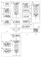
FIG. 6 is a block diagram showing the configuration of the main part of the play photo creating apparatus according to the present embodiment as seen from the functional aspect. 6 is functionally according to a photographing
撮影処理部7は、第1の制御部70と、撮像部71と、第1の表示・操作部72と、I/O制御部73と、照明部74と、第1の通信部75とによって構成されている。編集処理部8は、第2の制御部80と、第2の表示・操作部81,82と、第2の通信部83とによって構成されている。出力処理部9は、第3の制御部90と、第3の表示・操作部91と、印刷出力部92と、音声出力部93と、非接触通信部94と、第3の通信部95と、無線通信部96とによって構成されている。ネットワークアダプタである第1、第2および第3の通信部75,83,95は、LAN(Local Area Network)であるネットワーク6を介してそれぞれ相互に通信可能となっている。
The
撮像部71は、CCD等の撮像素子を用いて構成されるカメラ10に相当し、リアルタイムに画像を取り込んで当該画像(撮影画像)を表す画像信号を出力する。この画像信号は第1の制御部70に入力されて、その内部のメモリに撮影画像データとして一時的に記憶される。また、この撮影画像データは撮影画像信号として第1の制御部70から第1の表示・操作部72に供給され、当該撮影画像信号に基づく撮影画像がリアルタイムに表示される。
The imaging unit 71 corresponds to the
第1の表示・操作部72は、撮影操作用タッチパネル20に相当し、撮影画像に付加されるべき背景画像および前景画像を選択する操作やシャッター操作等を受け付ける。これらの操作を示す信号は、操作信号として第1の制御部70に入力される。ここで、利用者を撮影するための(選択された撮影メニューに対応する)所定の処理が開始されると、第1の表示・操作部72に利用者のための案内が表示され、その後の第1の制御部70からの指示に基づき、数秒程度の予め決められた時間の経過後にカメラ10の撮影方向にストロボ11〜14から閃光が放たれる。そのとき、利用者の撮影画像を表す信号として撮像部71から出力される画像信号が第1の制御部70に入力され、第1の制御部70内のメモリまたは補助記憶装置としてのハードディスク装置等に撮影画像データとして格納される。
The first display / operation unit 72 corresponds to the shooting
照明部74は、カメラ10の上下左右の位置に配置されたストロボ11,12,13L,13R,14に相当し、第1の制御部70からの指示に基づきI/O制御部73によって点灯/消灯および調光が制御される。I/O制御部73は、撮影ユニット3に内蔵されるI/O制御装置に相当し、第1の制御部70からの指示に基づき、照明部74を制御する。また、後述のコイン検出部(不図示)からの検出信号等の入力信号を第1の制御部70へ転送する。第1の通信部75は、撮影ユニット3に内蔵されるネットワークアダプタに相当し、ネットワーク6を介したデータ送受信の際のインタフェースとして機能する。
The
第1の制御部70は、撮影ユニット3に内蔵され、CPU、メモリ、フレームバッファ、タイマー、補助記憶装置等を含むコンピュータを中心に構成される制御装置に相当し、内部メモリに格納された所定プログラムをCPUが実行することにより、上述のようにして入力される操作信号等に基づき各部を制御するために、上述のように各部に指示を出す。また撮影された画像に基づいて落書き対象画像を生成する。生成された落書き対象画像はフレームバッファに書き込まれることにより、第1の表示・操作部72に表示される。さらに、第1の制御部70は、落書き対象画像に所定の背景画像や前景画像を描画した画像である合成画像を生成する。この落書き対象画像には、詳しくは後述するようにマスクの作成に使用されるキー色となる背景色が付されており、周知のクロマキー合成処理の手法に基づき、利用者の像のみを含む撮影画像部分を抽出し、当該撮影画像部分が背景画像中に嵌め込まれるように合成する。このように生成された合成画像はフレームバッファに書き込まれることにより第1の表示・操作部72に表示される。こうして撮影および合成画像の生成が終了すると、生成された合成画像は利用者の入力操作に応じて適宜選択された後、第1の通信部75を介して、編集ユニット4に対応する第2の制御部80へ送られる。
The
上記の構成要素の他、撮影ユニット3におけるコイン投入口26に投入されたコインを検出するためのコイン検出部(不図示)が更に撮影ユニット3に設けられており、第1の制御部70は、コイン検出部での検出結果に基づき、利用者に所定時間だけ撮影や背景画像および前景画像の選択や落書き等、本遊戯用写真作成装置によるプレイを許容するように各部を制御する。このコイン検出部による検出動作やその検出結果に基づく第1の制御部70による制御動作は、従来の遊戯用写真作成装置と同様であって周知であるので、その詳しい説明を省略する。
In addition to the above-described components, the photographing unit 3 is further provided with a coin detection unit (not shown) for detecting coins inserted into the
第2の制御部80は、編集ユニット4に内蔵され、CPU、メモリ、フレームバッファ、および補助記憶装置等を含むコンピュータを中心に構成される制御装置に相当し、内部メモリに格納された所定プログラムをCPUが実行することにより、編集処理に関する全体の制御を行う。すなわち第2の制御部80は、第2の表示・操作部を制御するGUI制御手段として機能する。また、第2の制御部80は、第1の制御部70から送られてきた落書き対象画像(撮影画像を含む画像)に対する落書き処理を行うための操作信号に基づき、その落書き対象画像に所定画像を描画した画像である合成画像を生成したり、落書き操作のための操作画面を生成し制御する。この操作画面および生成された合成画像や素材画像は利用者の指示に応じて対応する第2の表示・操作部81,82に表示される。さらに、第2の制御部80は、上記落書き編集操作を受け付ける前に、上記落書き対象画像に対する利用者による分割レイアウトの選択指示と、当該分割レイアウトに対応する位置に合成されるべき付加画像、ここではバナー画像および境界画像の種類をそれぞれ選択する指示とを受け付ける。選択された分割レイアウトを示す情報、合成されるべき付加画像、および生成された合成画像は出力ユニット5に送られる。なお、印刷出力部92が別の合成画像を出力中である場合には、その旨が表示されるとともに終了を待って送られる。
The
第2の表示・操作部81、82は、落書きのためのGUI表示手段として機能する編集操作用タッチパネル400に相当し、タッチペンを用いた利用者の操作を受け付ける。第2の通信部83は、編集ユニット4に内蔵されるネットワークアダプタに相当し、ネットワーク6を介したデータ送受信の際のインタフェースとして機能する。
The second display /
第3の制御部90は、出力ユニット5に内蔵され、CPU、メモリ、フレームバッファ、タイマー、および補助記憶装置等を含むコンピュータを中心に構成される制御装置に相当し、内部メモリに格納された所定プログラムをCPUが実行することにより、出力処理に関する全体の制御を行う。第3の制御部90は、第2の制御部80から送られてきた合成画像を合成画像データとしてメモリに格納する。印刷出力部92は出力ユニットに内蔵されるネットワークプリンタ35に相当し、メモリに格納された合成画像データを選択された分割レイアウトに応じて適宜にレイアウトし付加画像を合成した写真シール(または写真カード)として印刷する。印刷された写真シール等は、出力ユニット5の正面下方に設けられた取出口33から取り出される。なお、上記写真シールに印刷されるべき画像のレイアウトおよび合成処理は、第2の制御部80において行われてもよい。
The
また、第3の制御部90は、編集ユニット4から送られてきた合成画像に基づいて写真シール等の印刷処理を開始すると同時に、第2の制御部80において利用者により作成された合成画像のデータを図示されない外部の画像サーバへ送信する処理を開始するよう無線通信部96を制御する。
In addition, the
無線通信部96は、出力ユニット5に内蔵される携帯電話端末装置55に相当し、携帯電話端末によって画像サーバから当該合成画像をダウンロードできるように、第2の制御部80により作成された上記合成画像のデータを3G方式の無線通信方式で無線基地へ送信する。
The
またこのとき、画像サーバにおいて他の画像と識別するための識別番号(画像ID)が付与される。この識別番号は、典型的には製造時に各遊戯用自動写真作成装置に対して与えられるユニークなシリアルナンバー(例えば5桁)と、装置内で(製造後の初回の動作から)送信1回毎に順に付されるユニークな番号(例えば7桁)と、チェックサム(例えば2桁)とを含む。この識別番号も画像データとともに3G方式の無線通信方式で無線基地へ送信される。 At this time, an identification number (image ID) for identifying the image from another image is assigned in the image server. This identification number is typically a unique serial number (e.g., 5 digits) given to each game automatic photo creation device at the time of manufacture, and each transmission within the device (from the first operation after manufacture). Includes a unique number (for example, 7 digits) and a checksum (for example, 2 digits). This identification number is also transmitted to the wireless base together with the image data by the 3G wireless communication method.
さらに、第3の制御部90は、第2の制御部80から送られてきた分割レイアウト情報、付加画像の情報、および合成画像に基づいて写真シール等の印刷処理を開始すると同時に、利用者の入力操作を受け付けるための後述する操作画面を第3の表示・操作部91に表示する。この第3の表示・操作部91は出力操作用タッチパネル30に相当し、入力手段として機能する。出力操作用タッチパネル30は、液晶ディスプレイまたはCRT(Cathode Ray Tube)等の表示手段として機能するモニタと、その上面に積層され、入力座標を認識することができる1人用のタッチパネルから構成される。モニタは複数の画面に分割された操作画面を表示することができ、タッチパネルは分割された複数の画面ごとに利用者のタッチペンを用いた入力操作を受け付け、受け付けた入力操作を操作信号として第3の制御部90に入力する。
Furthermore, the
第3の通信部95は、出力ユニット5に内蔵されるネットワークアダプタに相当し、ネットワーク6を介したデータ送受信の際のインタフェースとして機能する。
The
ここで、第3の制御部90は、落書きを終えてから操作を始めるまでの間、補助記憶装置に予め記憶されているデモ画像(デモンストレーション用の画像)をフレームバッファに書き込むことにより第3の表示・操作部91に表示する。また音声出力部93は、スピーカ32に相当する。音声出力部93は、第3の表示・操作部91に表示される操作画面と連動して入力操作方法を利用者に説明し、また第3の表示・操作部91にデモ画像が表示されているときにデモ画像に応じた楽曲等を流す。なお、入力操作方法の説明や楽曲等は補助記憶装置としてのハードディス装置等に予め格納されている。
Here, the
その後、第3の制御部90は、第3の表示・操作部91の表示や音声出力部93による音声や効果音等により合成画像の印刷が完了するまで後述するミニゲームを利用者に提供し続ける。このミニゲームの内容も同様にハードディスク装置等に予め格納されている。
Thereafter, the
ここで、各制御装置において実行される上記所定プログラムは、例えば、そのプログラムを記録した記録媒体であるDVD−ROMによって提供される。すなわち、上記所定プログラムの記録媒体としてのDVD−ROMが補助記憶装置として制御装置内に内蔵されたDVD−ROM駆動装置に装着され、そのDVD−ROMから所定プログラムが読み出されて補助記憶装置としてのハードディスク装置にインストールされる。また、上記所定プログラムは、DVD−ROM以外の記録媒体(CD−ROM等)や通信回線を介して提供されてもよい。そして、本遊戯用写真作成装置の起動のための操作がなされると、ハードディスク装置にインストールされた所定プログラムは、制御装置内のメモリに転送されてそこに一時的に格納され、制御装置内のCPUによって実行される。これにより、制御装置による上記各部の制御処理が実現される。 Here, the predetermined program executed in each control device is provided by, for example, a DVD-ROM which is a recording medium on which the program is recorded. That is, a DVD-ROM as a recording medium for the predetermined program is attached to a DVD-ROM driving device built in the control device as an auxiliary storage device, and the predetermined program is read from the DVD-ROM as an auxiliary storage device. Installed on the hard disk drive. The predetermined program may be provided via a recording medium (CD-ROM or the like) other than a DVD-ROM or a communication line. Then, when an operation for starting the present photo creating device is performed, the predetermined program installed in the hard disk device is transferred to the memory in the control device and temporarily stored therein, It is executed by the CPU. Thereby, the control process of each part by the control device is realized.
なお、上記第1から第3までの制御部70,80,90は、異なるユニットに内蔵される異なるコンピュータを含む装置に相当するものとして説明したが、このような構成は一例であって、上記第1から第3までの制御部70,80,90は、2つ以下または4つ以上の装置により実現されてもよい。この場合には各装置において、それぞれ実現されるべき機能に応じたプログラムが実行される。また、撮影ユニット3、編集ユニット4、および出力ユニット5についても、2つ以下または4つ以上のユニットにより構成されてもよい。次に、本遊戯用写真作成装置における処理手順について説明する。
The first to
<3.遊戯用写真作成装置における処理手順>
上述したように、この遊戯用写真作成装置には、撮影ユニット3と編集ユニット4と出力ユニット5とが含まれている。撮影ユニット3では撮影処理が行われ、編集ユニット4では後述する落書き編集処理が行われ、出力ユニット5では出力処理が行われる。なお、或る利用者が撮影ユニット3でプレイしている時に他の利用者は編集ユニット4でプレイし、さらに他の利用者は出力ユニット5で合成画像を出力することができるように構成されている。すなわち、この遊戯用写真作成装置は、撮影処理と落書き編集処理と出力処理とを並行して行うことができる。以下に、撮影処理、落書き編集処理、および出力処理の手順の概要について説明する。
<3. Processing procedure in a photo creation device for play>
As described above, the play photo creating apparatus includes the photographing unit 3, the editing unit 4, and the
<3.1 撮影処理>
図7は、本実施形態における撮影処理の手順を示すフローチャートである。この遊戯用写真作成装置が使用されていない時(プレイが行われていない時)には、撮影操作用タッチパネル20にはデモ画像が表示されている。デモ画像の表示中に利用者がコイン投入口26にコインを投入すると、プレイが開始される(ステップS100)。
<3.1 Shooting process>
FIG. 7 is a flowchart showing the procedure of the photographing process in the present embodiment. When the play photo creation device is not used (when no play is performed), a demonstration image is displayed on the shooting
プレイが開始されると、第1の制御部70は、利用者による撮影モードの選択を受け付ける(ステップS110)。ステップS110では、例えば画質(具体的にはコントラストが高いくっきりとした画質、柔らかなふんわりとした画質、または透明感のあるクールな画質のうちのいずれか)を選択し、明るさを選択し、自動で撮影するか手動で撮影するかを選択し、自動で撮影する場合には撮影用テーマの選択が行われる。この場合、第1の制御部70は、予め用意された複数の撮影用テーマの中から1つ以上の撮影用テーマを利用者に選択させるための画面を撮影操作用タッチパネル20に表示し、利用者による選択操作を受け付ける。そして、第1の制御部70は、利用者の選択操作に基づいて選択情報を取得し、選択された撮影用テーマに基づいて、撮影の際に使用するフレームと背景との組み合わせを決定する。また手動で撮影する場合は、上記フレームと背景とを利用者が自由に決定する。その後、ステップS120に進み、撮影が行われる。この撮影により、撮影画像データが第1の制御部70のメモリに格納される。
When the play is started, the
ステップS130では、撮影画像に基づいて生成された落書き対象画像(撮影画像を含む画像)が、撮影操作用タッチパネル20に表示される。詳しくは、ステップS130の処理が行われる都度、図5に示した撮影操作用タッチパネル20の落書き対象画像表示領域203に落書き対象画像が順次追加表示される。その後、ステップS140に進み、第1の制御部70は、予め定められた枚数の撮影が終了したか否かを判定する。判定の結果、当該枚数の撮影が終了していればステップS150に進み、当該枚数の撮影が終了していなければステップS120に戻る。なお、実際には撮影のための制限時間(例えば3分)が設けられる。
In step S <b> 130, a graffiti target image (an image including a captured image) generated based on the captured image is displayed on the capturing
ステップS150では、複数の落書き対象画像の中から実際の落書き対象となる画像の(利用者による)選択が行われる。具体的には、第1の制御部70は、落書きおよび印刷に使用する画像を利用者に選択させるために、落書き対象画像の一覧を撮影操作用タッチパネル20に表示し、利用者による選択操作を受け付ける。そして、第1の制御部70は、利用者によって選択された画像を実際の落書き対象画像として第2の制御部80に送る。ステップS150の終了後、ステップS160に進む。ステップS160では、案内画面の表示が行われる。具体的には、第1の制御部70は、利用者を編集ユニット4のいずれか(4aまたは4b)に導くための画面を撮影操作用タッチパネル20に表示する。これにより、撮影処理が終了する。
In step S150, an image to be actually graffitied is selected (by the user) from a plurality of graffiti subject images. Specifically, the
<3.2 落書き編集処理>
図8は、本実施形態における落書き編集処理の手順を示すフローチャートである。第2の制御部80が所定のプログラムに基づき図8に示すように動作することで、この落書き編集処理が実現される。この処理では、上述した撮影処理の終了後、第2の制御部80は、ネットワーク(LAN)6を介して第1の制御部70から送られる落書き対象画像を取得する(ステップS200)。
<3.2 Graffiti editing process>
FIG. 8 is a flowchart showing the procedure of graffiti editing processing in the present embodiment. The graffiti editing process is realized by the
次に、ステップS210では、出力される写真をレイアウトするための分割パターンの選択が行われる。具体的には、第2の制御部80は、予め用意された複数の分割パターンの中からいずれかの分割パターンを利用者に選択させるための操作画面を編集操作用タッチパネル400に表示し、利用者による選択操作を受け付ける。この操作画面については詳しく後述する。そして、第2の制御部80は、利用者の選択操作に基づいて、分割パターンの選択情報を取得する。なお、このような分割パターンの選択動作は、撮影ユニット3または出力ユニット5において行われてもよい。
Next, in step S210, a division pattern for laying out an output photo is selected. Specifically, the
続いて、ステップS212では、分割パターンの中に含まれる合成画像のうち、他よりも大きくレイアウトされるべき合成画像である特定画像を利用者に選択させるための操作画面を編集操作用タッチパネル400に表示し、利用者による選択操作を受け付ける。この操作画面についても詳しく後述する。そして、第2の制御部80は、利用者の選択操作に基づいて、特定画像の選択情報を取得する。なお、大きくレイアウトされるべき合成画像は選択されない構成であってもよいし、一番大きくレイアウトされるべき合成画像と、2番目に大きくレイアウトされるべき合成画像とを利用者に選択させる構成など、分割パターンに基づき配置されるべき合成画像を所定の基準によって選択する構成であってもよい。
Subsequently, in step S212, an operation screen for causing the user to select a specific image that is a composite image to be laid out larger than the other of the composite images included in the division pattern is displayed on the editing
次に、ステップS214では、分割パターンの選択とは異なる特徴的な内容を有するシートデザインの選択が行われる。具体的には、第2の制御部80は、予め用意された複数のバナー画像(枠のパターン)および境界画像(切り取り線のパターン)の中からいずれかの画像(パターン)を利用者にそれぞれ選択させるための操作画面を編集操作用タッチパネル400に表示し、利用者による選択操作を受け付ける。このシートデザインを選択するための操作画面についても詳しく後述する。そして、第2の制御部80は、利用者の選択操作に基づいて、シートデザインの選択情報(具体的にはバナー画像と境界画像の選択情報)を取得する。
Next, in step S214, a sheet design having characteristic contents different from the selection of the division pattern is selected. Specifically, the
こうして上記操作画面における利用者の選択(S210〜S214)が終了した後、タイマー46が所定の時間(具体的には、落書きを許可する時間)に設定され、カウントダウンが開始される(ステップS220)。 After the selection of the user on the operation screen (S210 to S214) is completed in this way, the timer 46 is set to a predetermined time (specifically, a time for allowing graffiti), and a countdown is started (step S220). .
タイマー46のカウントダウン開始後、編集ユニット4を構成するユニット4a,4bのそれぞれの編集操作用タッチパネル400において、落書き編集操作画面が表示され、利用者による落書き操作(描画操作)が受け付けられる(ステップS230〜S250)。なおこの落書き編集処理時において、編集ユニット4では、撮影画像に基づく落書き対象画像に対する編集操作の他に、デコメール画像等の素材画像を作成するための編集操作が受け付けられてもよい。
After the countdown of the timer 46 starts, a doodle editing operation screen is displayed on the editing
上記処理は、具体的には編集操作画面内のボタンやツールなどの1つをタッチペンでタッチすると、その座標値が入力され(S230)、対応する落書き画面処理(S240)が行われる。その後ステップS250においてタイマー46の残り時間が0になる(または利用者が終了させる操作を行う)ことにより落書きが終了したかが判定され、終了していない場合(ステップS250においてNoの場合)にはステップS230に戻り、落書きが終了するまで処理が繰り返され、落書きが終了した場合(ステップS250においてYesの場合)には、処理はステップS260に進む。 Specifically, when one of the buttons and tools in the editing operation screen is touched with a touch pen, the coordinate value is input (S230), and the corresponding graffiti screen processing (S240) is performed. Thereafter, in step S250, the remaining time of the timer 46 becomes 0 (or the user performs an operation to end), and it is determined whether or not the graffiti has ended. If not (if No in step S250), Returning to step S230, the process is repeated until the graffiti ends. If the graffiti ends (Yes in step S250), the process proceeds to step S260.
ステップS260では、案内画面の表示が行われる。具体的には、第2の制御部80は、利用者を出力ユニット5に導くための画面を編集操作用タッチパネル400に表示する。これにより、落書き編集処理が終了する。落書き編集処理が終了すると、出力ユニット5において、編集ユニット4から送られてきた合成画像および分割レイアウト情報などに基づいて写真シール等の印刷処理が開始されることなどについては前述した通りである。次に、上述した各操作画面の構成について、図9から図11までを参照して詳しく説明する。
In step S260, a guidance screen is displayed. Specifically, the
<4.各操作画面の構成>
図9は、分割パターンを利用者に選択させるための操作画面を示す図である。図9に示される操作画面401は、その下半部において、利用者により選択可能に表示される複数の(図中では点線で囲まれた矩形領域として示される4つの)分割パターンを含む2人用分割パターン群431と、同様に選択可能な複数の分割パターンを含む3人用分割パターン群432と、同様に選択可能な複数の分割パターンを含む大人数用分割パターン群433とを含み、その上半部において、選択された分割パターンで複数の合成画像がレイアウトされた写真シールの画像例が表示されるプレビュー領域410と、最終的に選択を確定させる決定ボタン420とを含む。
<4. Configuration of each operation screen>
FIG. 9 is a diagram showing an operation screen for allowing the user to select a division pattern. The
例えば、2人用分割パターン群431には、選択可能な4つの分割パターン例が示されており、それぞれ配置されるべき撮影画像の位置や大きさが異なるように予め定められている。ここで利用者が2人の場合には、利用者はこの2人用分割パターン群431に含まれる4つの分割パターン例から好ましいと考える1つの分割パターン例をタッチペンでタッチすることにより選択する。なお、利用者が2人であっても、利用者は3人用分割パターン群432または大人数用分割パターン群433に含まれる分割パターン例を選択することができる。
For example, in the two-person divided
こうして利用者によって或る分割パターンが選択されると、ステップS200において第1の制御部70から取得された落書き対象画像を、上記選択された分割パターンに合わせてレイアウトすることにより得られる写真シールの画像に相当する縮小画像(プレビュー画像)がプレビュー領域410に表示される。なお、後述するように、各分割パターンに配置されるべき合成画像の大きさは通常複数種類あって、他よりも大きくレイアウトされるものが含まれており、後で利用者により選択可能となっている。しかしこの時点では未だ利用者により画像の選択がなされていないため、他よりも大きくレイアウトされるべき合成画像は、例えば落書き対象画像の最初の一枚目などに予め定められており(固定的に)選択される。
When a certain division pattern is selected by the user in this way, the photo sticker obtained by laying out the graffiti target image acquired from the
また、ここで利用者が異なる分割パターンを選択すると、上記プレビュー領域410には選択された分割パターンに合わせてレイアウトされた異なるプレビュー画像が表示される。そうして利用者が好ましいレイアウトの分割パターンを決定すると、利用者によって決定ボタン420が押下(選択)され、分割パターンを利用者に選択させる処理(S210)が終了し、大きくレイアウトされるべき合成画像を利用者に選択させる処理(S212)が開始される。
If the user selects a different division pattern, a different preview image laid out in accordance with the selected division pattern is displayed in the
図10は、他よりも大きくレイアウトされるべき合成画像を利用者に選択させるための操作画面を示す図である。図10に示される操作画面402は、その下半部において、複数の(図では6つの)落書き対象画像が利用者により選択可能に表示される落書き対象画像表示領域441を含み、その上半部において、利用者により選択された合成画像が大きくレイアウトされた写真シールの画像例が表示されるプレビュー領域410と、最終的に選択を確定させる決定ボタン420とを含む。
FIG. 10 is a diagram showing an operation screen for allowing the user to select a composite image to be laid out larger than the others. The
ここで、プレビュー領域410には、利用者が落書き対象画像表示領域441に示される落書き対象画像を未だ選択していない状態では、図9に示すプレビュー領域410と同一のプレビュー画像が表示される。すなわち上記のように図9に示す操作画面401において選択された分割パターンであって、初期的に(固定的に)決定された或る落書き対象画像が大きくレイアウトされた分割パターンに基づき、写真シールに相当する画像の縮小画像が図10に示すプレビュー領域410に表示される。
Here, in the
その後、利用者が大きくレイアウトしたい落書き対象画像を表示する落書き対象画像表示領域441を選択すると、上記のように選択された分割パターンであって、初期的に(固定的に)決定された落書き対象画像に代えて、選択された落書き対象画像が大きくレイアウトされた分割パターンの写真シールに相当する画像の縮小画像が図10に示すプレビュー領域410に表示される。
Thereafter, when the graffiti target
また、ここで利用者が異なる落書き対象画像を表示する落書き対象画像表示領域441を選択すると、上記プレビュー領域410には選択された落書き対象画像が大きくレイアウトされた異なるプレビュー画像が表示される。そうして利用者が最終的に大きくレイアウトしたい落書き対象画像を決定すると、利用者によって決定ボタン420が押下(選択)され、大きくレイアウトされるべき合成画像を利用者に選択させる処理(S212)が終了し、シートデザインの選択処理(S214)が開始される。
If the user selects a graffiti target
図11は、シートデザインを利用者に選択させるための操作画面を示す図である。図11に示される操作画面403は、その左半部において、写真シールの外枠近傍部分に記載されるべき文字や図形を示す画像(以下「バナー画像」という)のサンプル画像を利用者により選択可能に表示する複数の(図では4つの)バナー画像サンプル表示領域455〜458と、選択されたバナー画像をその配置態様を含めてより詳細に表示する選択バナー画像サンプル表示領域451と、写真シールにおける合成画像の境界に付される切り取り線等を示す画像(以下「境界画像」という)のサンプル画像を利用者により選択可能に表示する複数の(図では4つの)境界画像サンプル表示領域465〜468と、選択された境界画像をその配置態様を含めてより詳細に表示する選択境界画像サンプル表示領域461とを含み、その右半部において、選択されたバナー画像および境界画像を含み選択された分割パターンで複数の合成画像がレイアウトされた写真シールの画像例が表示されるプレビュー領域410と、最終的に選択を確定させる決定ボタン420とを含む。
FIG. 11 is a diagram showing an operation screen for allowing the user to select a sheet design. In the left half of the
ここで、図11に示されるように、バナー画像サンプル表示領域455には、利用者により選択されたことを示す強調枠(太枠)が付されており、この選択されたバナー画像サンプル表示領域455に表示されるバナー画像は「Diki Doki」という文字により構成されている。なお、その他のバナー画像サンプル表示領域456〜458に表示されるバナー画像も文字により構成されているが、バナー画像は文字以外の記号や、図形、模様などであってもよい。
Here, as shown in FIG. 11, the banner image
また選択されたバナー画像は、写真シール全体に対してどのように配置されるか利用者にわかりにくいため、図11に示される選択バナー画像サンプル表示領域451においてその配置パターンがわかりやすく表示される。なお、ここではその他のバナー画像サンプル表示領域456〜458に表示されるバナー画像も、写真シールの外側部分(典型的には周辺の余白部分)に表示されるが、例えば写真シールの上下または左右に分かつ中心線付近に余白が設けられているレイアウトの分割パターンであれば、当該余白部分にバナー画像が配置される構成であってもよいし、合成画像上にバナー画像が配置される構成であってもよく、その配置位置は写真シールにおける(典型的にはネットワークプリンタ35の)印刷可能領域内であれば特に限定はない。もっとも、余白領域にバナー画像を印刷すればその内容が利用者に視認されやすいため好ましい。
Further, since it is difficult for the user to understand how the selected banner image is arranged with respect to the entire photo sticker, the arrangement pattern is displayed in an easy-to-understand manner in the selected banner image
このようにバナー画像は写真シールに配置される画像の部分的な一例に過ぎず、典型的には繰り返しパターンとなるように写真シールに印刷される。また、このようなバナー画像の印刷パターンおよび印刷位置は、分割パターンに関連付けられて予め定められている。すなわち、各分割パターンにはバナー画像を配置するのに適した位置(例えば余白部分であるとか、全体的なデザインを考慮して適した位置など)があり、第2の制御部80は、このバナー画像を配置すべき位置(および繰り返しパターンなど)を分割パターン毎に記憶している。なお、分割パターンがグループ化されており、当該グループ毎に上記配置位置が記憶されていてもよいし、また或るバナー画像が全ての分割パターンにおいて同一の配置位置となっていてもよい。このように、各バナー画像の配置位置等を各分割パターンに関連付けてそれぞれ予め記憶しておくことにより、利用者がバナー画像(の部分)を選択するだけで、選択された分割パターンに適した位置に(および繰り返しパターンで)自動的に選択されたバナー画像を配置することができ、写真シールに対してバナー画像を付加する編集ないし落書きを短時間で簡単に行うことができる。 As described above, the banner image is only a partial example of the image arranged on the photo sticker, and is typically printed on the photo sticker so as to form a repeated pattern. Also, the print pattern and print position of such a banner image are determined in advance in association with the division pattern. That is, each division pattern has a position suitable for placing a banner image (for example, a margin part or a position suitable in consideration of the overall design). The position where the banner image is to be arranged (and the repeated pattern, etc.) is stored for each divided pattern. It should be noted that the division patterns are grouped, and the arrangement position may be stored for each group, or a certain banner image may be the same arrangement position in all the division patterns. As described above, the arrangement position of each banner image is stored in advance in association with each division pattern, so that the user only needs to select (part of) the banner image and is suitable for the selected division pattern. An automatically selected banner image can be placed at a position (and in a repeating pattern), and editing or graffiti for adding a banner image to a photo sticker can be easily performed in a short time.
また、図11に示されるように、境界画像サンプル表示領域466には、利用者により選択されたことを示す強調枠(太枠)が付されており、この選択された境界画像サンプル表示領域466に表示される境界画像は点線上に配置された多数の白い丸印の記号からなる。なお、その他の境界画像サンプル表示領域465,467,468に表示される境界画像も記号(マーク)からなるが、境界画像は記号以外の文字や、図形、模様などであってもよい。さらにこの境界画像は、所定の幅を有する白線であってもよい。そうすれば境界である白線を挟む2つの合成画像をハサミなどで切り離しやすくなる。
Further, as shown in FIG. 11, the boundary image
また選択された境界画像は、合成画像の境界に対してどのように配置されるか利用者にわかりにくいため、図11に示される選択境界画像サンプル表示領域461においてその配置パターンがわかりやすく表示される。なお、ここではその他の境界画像サンプル表示領域465,467,468に表示される境界画像も、写真シールに含まれる多数の合成画像の境界上に典型的には境界に接する2つの合成画像に共に差し掛かるように表示されるが、例えばこれら2つの合成画像の一方にのみ含まれるように表示されてもよいし、境界からやや離れた位置に表示されてもよいし、境界の一部にのみ表示されてもよく、その配置位置は写真シールにおける境界近傍の少なくとも一部であれば特に限定はない。
Further, since it is difficult for the user to understand how the selected boundary image is arranged with respect to the boundary of the composite image, the arrangement pattern is displayed in an easy-to-understand manner in the selected boundary image
このように表示される境界画像は写真シールに配置される画像の部分的な一例に過ぎず、典型的には繰り返しパターンとなるように写真シールに印刷される。また、このような境界画像の印刷パターンおよび印刷位置は、合成画像の境界を規定する分割パターンに関連付けられて予め定められている。すなわち、各分割パターンは多数の合成画像を接するようにレイアウトするため、合成画像の境界位置を当然に規定するものである。第2の制御部80は、この境界画像を配置すべき位置(および繰り返しパターンなど)を分割パターン毎に記憶している。このことにより、利用者が境界画像(の部分)を選択するだけで、選択された分割パターンに適した境界位置に(および繰り返しパターンで)自動的に選択された境界画像を配置することができ、写真シールに対して境界画像を付加する編集ないし落書きを短時間で簡単に行うことができる。
The border image displayed in this way is only a partial example of the image arranged on the photographic sticker, and is typically printed on the photographic sticker so as to form a repetitive pattern. Further, the printing pattern and printing position of such a boundary image are determined in advance in association with the division pattern that defines the boundary of the composite image. That is, since each divided pattern is laid out so as to contact a large number of composite images, the boundary position of the composite image is naturally defined. The
以上のように、利用者が写真シールに配置したいバナー画像を表示するバナー画像サンプル表示領域455と、配置したい境界画像を表示する境界画像サンプル表示領域466とを選択すると、選択バナー画像サンプル表示領域451および選択境界画像サンプル表示領域461に配置パターンをわかりやすく示す画像がそれぞれ表示されるとともに、上記選択された分割パターンに基づく写真シールに相当する画像に対して、選択されたバナー画像および境界画像を付加された写真シールに相当する画像の縮小画像が図11に示すプレビュー領域410に表示される。
As described above, when the user selects the banner image
なお、第2の制御部80における処理能力等の理由により、バナー画像および境界画像の付加(すなわち画像合成)およびその表示に時間がかかる場合には、選択バナー画像サンプル表示領域451および選択境界画像サンプル表示領域461が利用者によって選択可能であって、当該領域が利用者によって選択されるときに、上記画像が合成された写真シールに相当する画像の縮小画像をプレビュー領域410に表示する構成であってもよい。
If it takes time to add a banner image and a boundary image (that is, image synthesis) and display it for reasons such as processing capability in the
そうして利用者が最終的に付加したいバナー画像および境界画像を決定すると、利用者によって決定ボタン420が押下(選択)され、シートデザインの選択処理(S214)が終了し、上述した落書き編集処理(S220〜)が開始される。その後落書き編集処理が終了し、出力ユニット5において印刷される写真シールは、図12に示されるように、上記各操作画面403において利用者により選択されたレイアウトおよびシートデザインとなる。
When the user finally determines the banner image and the boundary image to be added, the
なお、さらに当該自動写真作成装置に関連する情報、例えば作成した合成画像を取得することができるように構成されたウェブサイトのURLや当該合成画像を識別するための前述した画像ID、宣伝などを示す文字などをバナー画像の他に、またはバナー画像として写真シートの典型的には余白部分に印刷してもよい。また、本実施形態の構成では、バナー画像および境界画像の双方が選択される構成であるが、これらのうちの一方のみが選択され合成される構成であってもよい。 In addition, information related to the automatic photo creation device, for example, the URL of a website configured to be able to acquire the created composite image, the above-described image ID for identifying the composite image, advertisement, etc. Characters to be shown may be printed as a banner image or typically as a banner image on a photographic sheet. In the configuration of the present embodiment, both the banner image and the boundary image are selected. However, only one of them may be selected and combined.
図12は、出力される写真シールを示す図である。図12に示されるように、写真シール600は、多数の合成画像と、図11に示す操作画面403に対する利用者の選択操作により選択されたバナー画像および境界画像に対応するバナー画像601および境界画像602とが印刷されており、上記印刷面を含むシールシートと、当該シールシートの印刷面と反対側の粘着面に対して剥離可能に接着されている台紙とからなる。典型的には、写真シールはポストカードサイズであって、横147[mm]、縦100[mm]の矩形形状を有している。なお、このような写真シールに代えて、粘着面を有しない写真カードなど、およそ合成画像を印刷可能な印刷媒体が使用されていればよい。
FIG. 12 is a diagram showing an output photographic sticker. As shown in FIG. 12, the
ここで、図12に示される多数の合成画像の配置レイアウトは、分割パターンを利用者に選択させる処理(S210)において、図9に示される操作画面401に対する利用者の選択操作により選択された分割パターンに基づくものである。
Here, the layout layout of a large number of composite images shown in FIG. 12 is the division selected by the user's selection operation on the
また、図12に示される多数の合成画像のうちの他より大きい4つの合成画像は、大きくレイアウトされるべき合成画像を利用者に選択させる処理(S212)において、図10に示される操作画面402に対する利用者の選択操作により選択された合成画像である。
In addition, in the process of causing the user to select a composite image to be laid out larger among the four composite images larger than the other composite images shown in FIG. 12 (S212), the
ここで、(もちろん1人であってもよいが)複数の利用者によって利用される自動写真作成装置における出力ユニット5から出力される1枚の写真シールは、複数の利用者で分けて利用することが多く、ハサミなどで写真シールを合成画像毎に切り分けて使用することが多い。このとき、境界画像は、合成画像の境界に接する2つの合成画像に共に差し掛かるように合成されているので、境界画像を二分するように切断すれば、合成画像を境界できれいに分断することができる。なお、このように分断するための切り取り線として利用者に認識させやすくするため、境界画像は境界に沿って点線状に伸びるよう間隔を空けて配置される複数の図形からなることが好ましい。また全ての合成画像を利用者にきれいに分断させるためには、当該境界画像が合成画像の境界全てに沿って配置されることが好ましい。
Here, one photo sticker output from the
また写真シールが切り分けられる場合、バナー画像の部分は合成画像から切り離されることが多いが、境界画像は境界に接する2つの合成画像に差し掛かるように付加されているため、その半分(または四半分)が切り離された合成画像に残る。このことにより、切り離された合成画像に特徴的なデザインを付与することができる。 When the photo sticker is cut, the banner image is often cut off from the composite image, but the border image is added so as to reach the two composite images in contact with the border. ) Remains in the separated composite image. This makes it possible to give a characteristic design to the separated composite image.
図13は、図12に示される合成画像のうちの小さい合成画像を含む部分を他から切り離して得られる写真シール部分を示す図である。この図13に示される写真シール部分の外周形状は実際には矩形形状であるため、常に図13に示すような形状に見えるわけではない。しかし、例えば紙などの白い物体に対して当該写真シール部分を(その粘着面が接するようにして)貼付すると、境界画像を構成する白い丸印の外周が写真シールの外周境界部分であるかのように見える。そのため、全体として当該写真シール部分の外周が内側に欠けた、切手様の形状に見えることになる。また、境界画像を構成する白い丸印に代えて、例えば菱形印を使用すれば、切り離された写真シール部分の外周形状がノコギリ歯様のギザギザした形状であるかのように見せることができる。このように、境界画像の形状を工夫することにより、自動写真作成装置(によって出力される写真シール)の遊戯性をさらに高めることができる。 FIG. 13 is a diagram showing a photographic sticker portion obtained by separating a portion including a small composite image from other composite images shown in FIG. Since the outer peripheral shape of the photograph sticker portion shown in FIG. 13 is actually a rectangular shape, it does not always look like the shape shown in FIG. However, for example, if the photo sticker part is attached to a white object such as paper (with its adhesive surface in contact), the outer periphery of the white circle constituting the border image is the outer border part of the photo sticker. looks like. Therefore, it looks like a postage stamp with the outer periphery of the photographic sticker portion missing inside. If, for example, rhombus marks are used instead of the white circles constituting the boundary image, the outer peripheral shape of the cut off photo sticker portion can be seen as if it is a sawtooth-like jagged shape. Thus, by devising the shape of the boundary image, the playability of the automatic photo creation device (photo sticker output by) can be further enhanced.
なお、前述したようにこの境界画像が所定の幅を有する白線である場合、さらに当該白線の外縁から2つの合成画像側へそれぞれ突出するよう配置された(上記白い丸印に対応する)2つの半円が白線に沿って所定の間隔を空けて配置されるような形状であってもよい。そうすれば境界である白線を挟む2つの合成画像をハサミなどで切り離しやすくすることができるとともに、切り離して得られる写真シールを図13に示すように切手様の形状に見せることができる。このことは、上記の菱形などを白線の外縁に付加する構成であっても同様であり、境界画像の形状を工夫することにより、境界で切り離しやすくすることができるとともに、遊戯性をさらに高めることもできる。 As described above, when the boundary image is a white line having a predetermined width, two boundary images (corresponding to the white circles) arranged so as to protrude from the outer edge of the white line to the two composite image sides, respectively. The shape may be such that the semicircles are arranged at predetermined intervals along the white line. Then, it is possible to easily separate the two composite images sandwiching the white line that is the boundary with scissors or the like, and it is possible to make the photograph sticker obtained by the separation look like a postage stamp as shown in FIG. This is the same even when the above-mentioned rhombus is added to the outer edge of the white line, and by devising the shape of the boundary image, it can be easily separated at the boundary, and the playability is further enhanced. You can also.
<5.効果>
以上のように、本実施形態では、分割パターンに関連付けてバナー画像または境界画像の配置位置等を予め記憶させておき、選択された分割パターンに応じて選択されたバナー画像または境界画像の配置位置を決定するので、写真シールに含まれる個別の合成画像に対して行うことが困難または不可能な態様の落書き、例えはレイアウトされる多数の合成画像の間に枠を書き込んだり、合成画像が占める領域以外の写真シールの余白領域にバナー画像を配置するような落書きを、レイアウトの分割パターンと付加されるべき画像とを選択するだけで簡単かつ短時間で行うことができる。
<5. Effect>
As described above, in the present embodiment, the arrangement position of the banner image or the boundary image is stored in advance in association with the division pattern, and the arrangement position of the banner image or the boundary image selected according to the selected division pattern. The graffiti is difficult or impossible to do with the individual composite images included in the photo sticker. For example, a frame is written between a large number of composite images to be laid out. Graffiti such as placing a banner image in the blank area of the photo sticker other than the area can be performed simply and in a short time by simply selecting the layout division pattern and the image to be added.
3…撮影ユニット
4…編集ユニット
5…出力ユニット
6…ネットワーク(LAN)
10…カメラ
20…撮影操作用タッチパネル
30…出力操作用タッチパネル
31…非接触通信ポート(赤外線ポート)
32…スピーカ
35…ネットワークプリンタ
70…第1の制御部
72…第1の表示・操作部(撮影操作用タッチパネル)
75…第1の通信部(ネットワークアダプタ)
80…第2の制御部
81,82…第2の表示・操作部(編集操作用タッチパネル)
90…第3の制御部
91…第3の表示・操作部(出力操作用タッチパネル)
92…印刷出力部(ネットワークプリンタ)
93…音声出力部(スピーカ)
94…非接触通信部(非接触通信ポート)
80…第2の制御部
81,82…第2の表示・操作部(編集操作用タッチパネル)
83…第2の通信部(ネットワークアダプタ)
401〜403…操作画面
600…写真シール
601…境界画像
602…バナー画像
3 ... Shooting unit 4 ... Editing
DESCRIPTION OF
32 ...
75. First communication unit (network adapter)
80 ...
90 ...
92 ... Print output section (network printer)
93 ... Audio output unit (speaker)
94 ... Non-contact communication part (non-contact communication port)
80 ...
83 ... 2nd communication part (network adapter)
401-403 ...
Claims (4)
複数の画像を印刷媒体に印刷する際のレイアウトを示す分割パターンを、予め用意された複数の分割パターンの中から決定する分割パターン決定部と、
決定された分割パターンで示されるレイアウトに従って複数の画像を配置したプレビュー画像を表示するプレビュー表示部と、
決定された分割パターンが他よりも大きくレイアウトされる特別画像配置領域を有する場合、前記特別画像配置領域に配置する画像である特別画像を複数の画像の中から利用者に選択させる特別画像選択部と、
選択された特別画像を利用者に確定させる特別画像確定部と、を備え、
前記特別画像選択部は、前記特別画像が確定されるまでの間、前記特別画像配置領域に配置されている画像とは異なる画像の利用者による選択を可能とし、
前記プレビュー表示部は、前記異なる画像が選択されると、前記特別画像配置領域に前記異なる画像が配置されたプレビュー画像へ切り替えるように表示し、
前記分割パターン決定部は、
前記複数の分割パターンのいずれかを利用者に選択させる分割パターン選択部と、
利用者からの操作入力を受け付けると、前記複数の画像を印刷媒体に印刷する際のレイアウトを示す分割パターンを利用者によって選択されている分割パターンに決定する分割パターン確定部とを含み、
前記分割パターン確定部に対する利用者による操作入力が受け付けられるまでの間、利用者による分割パターンの選び直しを可能とし、
前記プレビュー表示部は、
選択された分割パターンで示されるレイアウトに従って前記撮影画像に基づく複数の画像を配置した分割プレビュー画像を、利用者に選択させるために表示されている前記複数の分割パターンと同じ画面上に表示し、
分割パターンの選び直しが行われるたびに、選び直された分割パターンに対応する分割プレビュー画像を表示することを特徴とする、遊戯用撮影装置。 An image generation unit that generates a plurality of images based on the captured images;
A division pattern determination unit that determines a division pattern indicating a layout for printing a plurality of images on a print medium from a plurality of division patterns prepared in advance;
A preview display unit for displaying a preview image in which a plurality of images are arranged according to the layout indicated by the determined division pattern;
When the determined division pattern has a special image arrangement area that is laid out larger than the other, a special image selection unit that allows a user to select a special image that is an image to be arranged in the special image arrangement area from a plurality of images When,
A special image confirmation unit that allows the user to confirm the selected special image,
The special image selection unit allows a user to select an image different from the image arranged in the special image arrangement area until the special image is determined,
When the different image is selected, the preview display unit displays so as to switch to a preview image in which the different image is arranged in the special image arrangement area ,
The division pattern determination unit
A division pattern selection unit that allows a user to select one of the plurality of division patterns;
When receiving an operation input from a user, including a division pattern determination unit that determines a division pattern indicating a layout when printing the plurality of images on a print medium as a division pattern selected by the user,
Until the operation input by the user for the division pattern determination unit is accepted, the user can reselect the division pattern,
The preview display section
Displaying a divided preview image in which a plurality of images based on the photographed image are arranged according to the layout indicated by the selected division pattern on the same screen as the plurality of division patterns displayed for the user to select,
A game photographing apparatus , wherein a divided preview image corresponding to a reselected divided pattern is displayed each time a divided pattern is reselected .
複数の画像を印刷媒体に印刷する際のレイアウトを示す分割パターンを、予め複数用意された複数の分割パターンの中から決定する分割パターン決定ステップと、
決定された分割パターンで示されるレイアウトに従って複数の画像を配置したプレビュー画像を表示するプレビュー表示ステップと、
決定された分割パターンが他よりも大きくレイアウトされる特別画像配置領域を有する場合、前記特別画像配置領域に配置する画像である特別画像を複数の画像の中から利用者に選択させる特別画像選択ステップと、
選択された特別画像を利用者に確定させる特別画像確定ステップと、を備え、
前記特別画像選択ステップでは、前記特別画像が確定されるまでの間、前記特別画像配置領域に配置されている画像とは異なる画像の利用者による選択を可能とし、
前記プレビュー表示ステップでは、前記異なる画像が選択されると、前記特別画像配置領域に前記異なる画像が配置されたプレビュー画像へ切り替えるように表示し、
前記分割パターン決定ステップは、
前記複数の分割パターンのいずれかを利用者に選択させる分割パターン選択ステップと、
利用者からの操作入力を受け付けると、前記複数の画像を印刷媒体に印刷する際のレイアウトを示す分割パターンを利用者によって選択されている分割パターンに決定する分割パターン確定ステップとを含み、
前記分割パターン確定ステップによって分割パターンが決定されるまでの間、利用者による分割パターンの選び直しを可能とし、
前記プレビュー表示ステップでは、
選択された分割パターンで示されるレイアウトに従って前記撮影画像に基づく複数の画像を配置した分割プレビュー画像を、利用者に選択させるために表示されている前記複数の分割パターンと同じ画面上に表示し、
分割パターンの選び直しが行われるたびに、選び直された分割パターンに対応する分割プレビュー画像を表示することを特徴とする、遊戯用撮影方法。 An image generation step for generating a plurality of images based on the captured images;
A division pattern determination step for determining a division pattern indicating a layout for printing a plurality of images on a print medium from a plurality of division patterns prepared in advance;
A preview display step for displaying a preview image in which a plurality of images are arranged according to the layout indicated by the determined division pattern;
A special image selection step for allowing a user to select a special image, which is an image to be arranged in the special image arrangement area, from a plurality of images when the determined division pattern has a special image arrangement area that is laid out larger than the others. When,
A special image confirmation step for allowing the user to confirm the selected special image,
In the special image selection step, the user can select an image different from the image arranged in the special image arrangement area until the special image is determined,
In the preview display step, when the different image is selected, a display is performed so as to switch to a preview image in which the different image is arranged in the special image arrangement region ,
The division pattern determination step includes
A division pattern selection step for allowing a user to select one of the plurality of division patterns;
Receiving an operation input from a user, including a division pattern determination step for determining a division pattern indicating a layout when printing the plurality of images on a print medium as a division pattern selected by the user;
Until the division pattern is determined by the division pattern determination step, the user can reselect the division pattern,
In the preview display step,
Displaying a divided preview image in which a plurality of images based on the photographed image are arranged according to the layout indicated by the selected division pattern on the same screen as the plurality of division patterns displayed for the user to select,
A game shooting method characterized by displaying a divided preview image corresponding to a reselected divided pattern every time a divided pattern is reselected .
撮影画像に基づいて、複数の画像を生成する画像生成ステップと、
複数の画像を印刷媒体に印刷する際のレイアウトを示す分割パターンを、予め複数用意された複数の分割パターンの中から決定する分割パターン決定ステップと、
決定された分割パターンで示されるレイアウトに従って複数の画像を配置したプレビュー画像を表示するプレビュー表示ステップと、
決定された分割パターンが他よりも大きくレイアウトされる特別画像配置領域を有する場合、前記特別画像配置領域に配置する画像である特別画像を複数の画像の中から利用者に選択させる特別画像選択ステップと、
選択された特別画像を利用者に確定させる特別画像確定ステップと、を実行させるプログラムであって、
前記特別画像選択ステップでは、前記特別画像が確定されるまでの間、前記特別画像配置領域に配置されている画像とは異なる画像の利用者による選択を可能とし、
前記プレビュー表示ステップでは、前記異なる画像が選択されると、前記特別画像配置領域に前記異なる画像が配置されたプレビュー画像へ切り替えるように表示し、
前記分割パターン決定ステップは、
前記複数の分割パターンのいずれかを利用者に選択させる分割パターン選択ステップと、
利用者からの操作入力を受け付けると、前記複数の画像を印刷媒体に印刷する際のレイアウトを示す分割パターンを利用者によって選択されている分割パターンに決定する分割パターン確定ステップとを含み、
前記分割パターン確定ステップによって分割パターンが決定されるまでの間、利用者による分割パターンの選び直しを可能とし、
前記プレビュー表示ステップでは、
選択された分割パターンで示されるレイアウトに従って前記撮影画像に基づく複数の画像を配置した分割プレビュー画像を、利用者に選択させるために表示されている前記複数の分割パターンと同じ画面上に表示し、
分割パターンの選び直しが行われるたびに、選び直された分割パターンに対応する分割プレビュー画像を表示することを特徴とする、遊戯用撮影プログラム。 On the computer,
An image generation step for generating a plurality of images based on the captured images;
A division pattern determination step for determining a division pattern indicating a layout for printing a plurality of images on a print medium from a plurality of division patterns prepared in advance;
A preview display step for displaying a preview image in which a plurality of images are arranged according to the layout indicated by the determined division pattern;
A special image selection step for allowing a user to select a special image, which is an image to be arranged in the special image arrangement area, from a plurality of images when the determined division pattern has a special image arrangement area that is laid out larger than the others. When,
A program for executing a special image determination step for determining a selected special image by a user,
In the special image selection step, the user can select an image different from the image arranged in the special image arrangement area until the special image is determined,
In the preview display step, when the different image is selected, a display is performed so as to switch to a preview image in which the different image is arranged in the special image arrangement region ,
The division pattern determination step includes
A division pattern selection step for allowing a user to select one of the plurality of division patterns;
Receiving an operation input from a user, including a division pattern determination step for determining a division pattern indicating a layout when printing the plurality of images on a print medium as a division pattern selected by the user;
Until the division pattern is determined by the division pattern determination step, the user can reselect the division pattern,
In the preview display step,
Displaying a divided preview image in which a plurality of images based on the photographed image are arranged according to the layout indicated by the selected division pattern on the same screen as the plurality of division patterns displayed for the user to select,
A game shooting program for displaying a divided preview image corresponding to a reselected divided pattern every time a divided pattern is reselected .
Priority Applications (1)
| Application Number | Priority Date | Filing Date | Title |
|---|---|---|---|
| JP2013151428A JP5742891B2 (en) | 2013-07-22 | 2013-07-22 | Photo sticker creation device |
Applications Claiming Priority (1)
| Application Number | Priority Date | Filing Date | Title |
|---|---|---|---|
| JP2013151428A JP5742891B2 (en) | 2013-07-22 | 2013-07-22 | Photo sticker creation device |
Related Parent Applications (1)
| Application Number | Title | Priority Date | Filing Date |
|---|---|---|---|
| JP2011063008A Division JP5333494B2 (en) | 2011-03-22 | 2011-03-22 | Photo sticker creation apparatus, photo sticker creation method, and program thereof |
Related Child Applications (1)
| Application Number | Title | Priority Date | Filing Date |
|---|---|---|---|
| JP2015087242A Division JP5790896B2 (en) | 2015-04-22 | 2015-04-22 | Game shooting device, game shooting method, and game shooting program |
Publications (3)
| Publication Number | Publication Date |
|---|---|
| JP2013254213A JP2013254213A (en) | 2013-12-19 |
| JP2013254213A5 JP2013254213A5 (en) | 2014-07-31 |
| JP5742891B2 true JP5742891B2 (en) | 2015-07-01 |
Family
ID=49951697
Family Applications (1)
| Application Number | Title | Priority Date | Filing Date |
|---|---|---|---|
| JP2013151428A Active JP5742891B2 (en) | 2013-07-22 | 2013-07-22 | Photo sticker creation device |
Country Status (1)
| Country | Link |
|---|---|
| JP (1) | JP5742891B2 (en) |
Family Cites Families (6)
| Publication number | Priority date | Publication date | Assignee | Title |
|---|---|---|---|---|
| JP3472770B2 (en) * | 2001-12-28 | 2003-12-02 | 株式会社アトラス | Automatic photography equipment |
| JP3927453B2 (en) * | 2002-06-24 | 2007-06-06 | 辰巳電子工業株式会社 | Automatic photo creation method and automatic photo creation device |
| JP2006345325A (en) * | 2005-06-09 | 2006-12-21 | Atlus Co Ltd | Automatic photographic apparatus |
| JP5098777B2 (en) * | 2008-04-18 | 2012-12-12 | フリュー株式会社 | Photo sticker creation apparatus, photo sticker creation method, and program |
| JP5110386B2 (en) * | 2008-09-03 | 2012-12-26 | フリュー株式会社 | Photo sticker creating apparatus and method, and program |
| JP4316001B1 (en) * | 2008-09-11 | 2009-08-19 | 株式会社メイクソフトウェア | Photography game machine, photography game method and photography game program |
-
2013
- 2013-07-22 JP JP2013151428A patent/JP5742891B2/en active Active
Also Published As
| Publication number | Publication date |
|---|---|
| JP2013254213A (en) | 2013-12-19 |
Similar Documents
| Publication | Publication Date | Title |
|---|---|---|
| JP5782873B2 (en) | Game shooting device, game shooting method and program | |
| JP5790896B2 (en) | Game shooting device, game shooting method, and game shooting program | |
| JP2018029343A (en) | Image processing apparatus, image processing method, and program | |
| JP5527460B2 (en) | Game shooting device, game shooting method and computer program | |
| JP6614386B2 (en) | Image processing apparatus, image processing method, and program | |
| JP5632104B2 (en) | Game shooting device, processing method and program for game shooting device | |
| JP5790034B2 (en) | Automatic photo creation device | |
| JP5742891B2 (en) | Photo sticker creation device | |
| JP5895394B2 (en) | Game shooting device, game shooting method, and game shooting program | |
| JP5333494B2 (en) | Photo sticker creation apparatus, photo sticker creation method, and program thereof | |
| JP2012177741A (en) | Automatic photograph creation device | |
| JP6156559B2 (en) | Game shooting device, game shooting method, and program | |
| JP6245529B2 (en) | Game shooting device, game shooting method and program | |
| JP5967275B2 (en) | Photographic game machine, its control method and control computer | |
| JP5672331B2 (en) | Photography game device, photography game method, and photography game program | |
| JP5251906B2 (en) | Photography game device, photography game method, and photography game program | |
| JP2012196908A5 (en) | ||
| JP6614374B2 (en) | Photography game machine, control method and program | |
| JP2013229778A (en) | Photograph imaging play device, image generation method and image generation program | |
| JP5974611B2 (en) | PHOTOGRAPHIC GAME DEVICE, IMAGE GENERATION METHOD, AND IMAGE GENERATION PROGRAM | |
| JP5887752B2 (en) | Photography game device, photography game method, and photography game program | |
| JP5660243B2 (en) | Game shooting device, game shooting method and computer program | |
| JP2015188256A (en) | Imaging apparatus for game, imaging method for game, and program | |
| JP5967283B2 (en) | Photo shooting game machine, its control method and control program | |
| JP2016184873A (en) | Photo taking game machine and control program |
Legal Events
| Date | Code | Title | Description |
|---|---|---|---|
| A621 | Written request for application examination |
Free format text: JAPANESE INTERMEDIATE CODE: A621 Effective date: 20140324 |
|
| A521 | Request for written amendment filed |
Free format text: JAPANESE INTERMEDIATE CODE: A523 Effective date: 20140616 |
|
| A871 | Explanation of circumstances concerning accelerated examination |
Free format text: JAPANESE INTERMEDIATE CODE: A871 Effective date: 20140616 |
|
| A975 | Report on accelerated examination |
Free format text: JAPANESE INTERMEDIATE CODE: A971005 Effective date: 20140709 |
|
| A131 | Notification of reasons for refusal |
Free format text: JAPANESE INTERMEDIATE CODE: A131 Effective date: 20140715 |
|
| A521 | Request for written amendment filed |
Free format text: JAPANESE INTERMEDIATE CODE: A523 Effective date: 20140903 |
|
| A131 | Notification of reasons for refusal |
Free format text: JAPANESE INTERMEDIATE CODE: A131 Effective date: 20141118 |
|
| A521 | Request for written amendment filed |
Free format text: JAPANESE INTERMEDIATE CODE: A523 Effective date: 20150119 |
|
| TRDD | Decision of grant or rejection written | ||
| A01 | Written decision to grant a patent or to grant a registration (utility model) |
Free format text: JAPANESE INTERMEDIATE CODE: A01 Effective date: 20150407 |
|
| A61 | First payment of annual fees (during grant procedure) |
Free format text: JAPANESE INTERMEDIATE CODE: A61 Effective date: 20150420 |
|
| R150 | Certificate of patent or registration of utility model |
Ref document number: 5742891 Country of ref document: JP Free format text: JAPANESE INTERMEDIATE CODE: R150 |
|
| R250 | Receipt of annual fees |
Free format text: JAPANESE INTERMEDIATE CODE: R250 |
|
| R250 | Receipt of annual fees |
Free format text: JAPANESE INTERMEDIATE CODE: R250 |
|
| R250 | Receipt of annual fees |
Free format text: JAPANESE INTERMEDIATE CODE: R250 |
|
| R250 | Receipt of annual fees |
Free format text: JAPANESE INTERMEDIATE CODE: R250 |
|
| R250 | Receipt of annual fees |
Free format text: JAPANESE INTERMEDIATE CODE: R250 |
|
| R250 | Receipt of annual fees |
Free format text: JAPANESE INTERMEDIATE CODE: R250 |