JP5741310B2 - Train length measuring device, train length measuring method, and train length measuring computer program - Google Patents
Train length measuring device, train length measuring method, and train length measuring computer program Download PDFInfo
- Publication number
- JP5741310B2 JP5741310B2 JP2011175083A JP2011175083A JP5741310B2 JP 5741310 B2 JP5741310 B2 JP 5741310B2 JP 2011175083 A JP2011175083 A JP 2011175083A JP 2011175083 A JP2011175083 A JP 2011175083A JP 5741310 B2 JP5741310 B2 JP 5741310B2
- Authority
- JP
- Japan
- Prior art keywords
- vehicle
- sensor
- train
- unit
- length
- Prior art date
- Legal status (The legal status is an assumption and is not a legal conclusion. Google has not performed a legal analysis and makes no representation as to the accuracy of the status listed.)
- Expired - Fee Related
Links
Images


Classifications
-
- G—PHYSICS
- G08—SIGNALLING
- G08G—TRAFFIC CONTROL SYSTEMS
- G08G1/00—Traffic control systems for road vehicles
- G08G1/07—Controlling traffic signals
- G08G1/08—Controlling traffic signals according to detected number or speed of vehicles
-
- G—PHYSICS
- G01—MEASURING; TESTING
- G01S—RADIO DIRECTION-FINDING; RADIO NAVIGATION; DETERMINING DISTANCE OR VELOCITY BY USE OF RADIO WAVES; LOCATING OR PRESENCE-DETECTING BY USE OF THE REFLECTION OR RERADIATION OF RADIO WAVES; ANALOGOUS ARRANGEMENTS USING OTHER WAVES
- G01S13/00—Systems using the reflection or reradiation of radio waves, e.g. radar systems; Analogous systems using reflection or reradiation of waves whose nature or wavelength is irrelevant or unspecified
- G01S13/02—Systems using reflection of radio waves, e.g. primary radar systems; Analogous systems
- G01S13/06—Systems determining position data of a target
- G01S13/08—Systems for measuring distance only
- G01S13/32—Systems for measuring distance only using transmission of continuous waves, whether amplitude-, frequency-, or phase-modulated, or unmodulated
- G01S13/34—Systems for measuring distance only using transmission of continuous waves, whether amplitude-, frequency-, or phase-modulated, or unmodulated using transmission of continuous, frequency-modulated waves while heterodyning the received signal, or a signal derived therefrom, with a locally-generated signal related to the contemporaneously transmitted signal
- G01S13/345—Systems for measuring distance only using transmission of continuous waves, whether amplitude-, frequency-, or phase-modulated, or unmodulated using transmission of continuous, frequency-modulated waves while heterodyning the received signal, or a signal derived therefrom, with a locally-generated signal related to the contemporaneously transmitted signal using triangular modulation
-
- G—PHYSICS
- G01—MEASURING; TESTING
- G01S—RADIO DIRECTION-FINDING; RADIO NAVIGATION; DETERMINING DISTANCE OR VELOCITY BY USE OF RADIO WAVES; LOCATING OR PRESENCE-DETECTING BY USE OF THE REFLECTION OR RERADIATION OF RADIO WAVES; ANALOGOUS ARRANGEMENTS USING OTHER WAVES
- G01S13/00—Systems using the reflection or reradiation of radio waves, e.g. radar systems; Analogous systems using reflection or reradiation of waves whose nature or wavelength is irrelevant or unspecified
- G01S13/02—Systems using reflection of radio waves, e.g. primary radar systems; Analogous systems
- G01S13/50—Systems of measurement based on relative movement of target
- G01S13/58—Velocity or trajectory determination systems; Sense-of-movement determination systems
- G01S13/583—Velocity or trajectory determination systems; Sense-of-movement determination systems using transmission of continuous unmodulated waves, amplitude-, frequency-, or phase-modulated waves and based upon the Doppler effect resulting from movement of targets
- G01S13/584—Velocity or trajectory determination systems; Sense-of-movement determination systems using transmission of continuous unmodulated waves, amplitude-, frequency-, or phase-modulated waves and based upon the Doppler effect resulting from movement of targets adapted for simultaneous range and velocity measurements
-
- G—PHYSICS
- G01—MEASURING; TESTING
- G01S—RADIO DIRECTION-FINDING; RADIO NAVIGATION; DETERMINING DISTANCE OR VELOCITY BY USE OF RADIO WAVES; LOCATING OR PRESENCE-DETECTING BY USE OF THE REFLECTION OR RERADIATION OF RADIO WAVES; ANALOGOUS ARRANGEMENTS USING OTHER WAVES
- G01S13/00—Systems using the reflection or reradiation of radio waves, e.g. radar systems; Analogous systems using reflection or reradiation of waves whose nature or wavelength is irrelevant or unspecified
- G01S13/66—Radar-tracking systems; Analogous systems
-
- G—PHYSICS
- G01—MEASURING; TESTING
- G01S—RADIO DIRECTION-FINDING; RADIO NAVIGATION; DETERMINING DISTANCE OR VELOCITY BY USE OF RADIO WAVES; LOCATING OR PRESENCE-DETECTING BY USE OF THE REFLECTION OR RERADIATION OF RADIO WAVES; ANALOGOUS ARRANGEMENTS USING OTHER WAVES
- G01S13/00—Systems using the reflection or reradiation of radio waves, e.g. radar systems; Analogous systems using reflection or reradiation of waves whose nature or wavelength is irrelevant or unspecified
- G01S13/88—Radar or analogous systems specially adapted for specific applications
- G01S13/91—Radar or analogous systems specially adapted for specific applications for traffic control
-
- G—PHYSICS
- G08—SIGNALLING
- G08G—TRAFFIC CONTROL SYSTEMS
- G08G1/00—Traffic control systems for road vehicles
- G08G1/01—Detecting movement of traffic to be counted or controlled
- G08G1/0104—Measuring and analyzing of parameters relative to traffic conditions
- G08G1/0108—Measuring and analyzing of parameters relative to traffic conditions based on the source of data
- G08G1/0116—Measuring and analyzing of parameters relative to traffic conditions based on the source of data from roadside infrastructure, e.g. beacons
-
- G—PHYSICS
- G08—SIGNALLING
- G08G—TRAFFIC CONTROL SYSTEMS
- G08G1/00—Traffic control systems for road vehicles
- G08G1/01—Detecting movement of traffic to be counted or controlled
- G08G1/0104—Measuring and analyzing of parameters relative to traffic conditions
- G08G1/0125—Traffic data processing
- G08G1/0133—Traffic data processing for classifying traffic situation
-
- G—PHYSICS
- G08—SIGNALLING
- G08G—TRAFFIC CONTROL SYSTEMS
- G08G1/00—Traffic control systems for road vehicles
- G08G1/01—Detecting movement of traffic to be counted or controlled
- G08G1/0104—Measuring and analyzing of parameters relative to traffic conditions
- G08G1/0137—Measuring and analyzing of parameters relative to traffic conditions for specific applications
- G08G1/0145—Measuring and analyzing of parameters relative to traffic conditions for specific applications for active traffic flow control
-
- G—PHYSICS
- G08—SIGNALLING
- G08G—TRAFFIC CONTROL SYSTEMS
- G08G1/00—Traffic control systems for road vehicles
- G08G1/01—Detecting movement of traffic to be counted or controlled
- G08G1/052—Detecting movement of traffic to be counted or controlled with provision for determining speed or overspeed
Description
本発明は、例えば、車両の位置の検知結果に基づいて車両の列の長さを測定する車列長測定装置、車列長測定方法及び車列長測定用コンピュータプログラムに関する。 The present invention relates to a vehicle train length measurement device, a train train length measurement method, and a vehicle train length measurement computer program that measure the length of a train of vehicles based on, for example, a detection result of the vehicle position.
交通量に関する情報を収集したり、信号を切り替えるタイミングを制御するための情報を得るために、一時的に停車している車両の列の長さ(以下、単に車列長と呼ぶ)を測定する技術が研究されている(例えば、特許文献1〜3を参照)。
例えば、特許文献1に開示された技術では、プローブ車両から取得したプローブ情報を用いて、プローブ車両が車両感知器の感知領域を通過した時刻及び信号待ち行列の末尾に到達した時刻及び到達位置が特定される。そしてその技術では、プローブ車両が車両感知器の感知領域を通過した時刻及び信号待ち行列の末尾に到達した時刻及び到達位置を用いて、任意の時刻にその感知領域を通過した車両が信号待ち行列の末尾となったときの位置が算出される。
また、特許文献2には、車両の進行方向と同じ方向にレンズを向けるようにカメラを設置し、車両の後方位置から道路の映像を撮影して車両待機行列の長さを測定する技術が開示されている。
さらに、特許文献3には、ブレーキ操作がされると、その時の車両の平均減速度を求めた後、制動距離を求め、その制動距離から車両が停止する到達位置を求める技術が開示されている。
In order to collect information on traffic volume and to obtain information for controlling the timing of switching signals, the length of a train of vehicles that are temporarily stopped (hereinafter simply referred to as the train length) is measured. Technology has been studied (see, for example, Patent Documents 1 to 3).
For example, in the technique disclosed in Patent Document 1, the probe information acquired from the probe vehicle is used to determine the time when the probe vehicle passes the sensing area of the vehicle detector, the time when the probe vehicle reaches the end of the signal queue, and the arrival position. Identified. In the technology, the time when the probe vehicle passes through the sensing area of the vehicle detector and the time when the probe vehicle arrives at the end of the signal queue and the arrival position are used. The position at the end of is calculated.
Patent Document 2 discloses a technique in which a camera is installed so that a lens is directed in the same direction as the traveling direction of a vehicle, a road image is taken from a rear position of the vehicle, and the length of a vehicle waiting queue is measured. Has been.
Furthermore,
しかし、特許文献1に開示された技術では、プローブ車両といった特殊な車両が実際に車両感知器の感知領域を通過する必要があり、そのため、車列長を求める手順が煩雑であった。
また、特許文献2に開示された技術では、車両を後方から撮影するカメラが用いられる。しかし、このようなカメラを設置するために、カメラを取り付けるための支柱を道路の側に新たに設置しなければならないおそれがあった。
さらに、特許文献3に開示された技術は、車両に搭載される装置に適用される。そのため、この技術が適用された装置は、その装置が搭載された車両の停止位置を予測できるものの、他の車両が停止しているか否かを知ることはできないので、車列長を求めることはできない。
However, in the technique disclosed in Patent Document 1, it is necessary for a special vehicle such as a probe vehicle to actually pass through the sensing area of the vehicle detector, and thus the procedure for obtaining the vehicle train length is complicated.
In the technique disclosed in Patent Document 2, a camera that captures a vehicle from behind is used. However, in order to install such a camera, there is a possibility that a support for mounting the camera must be newly installed on the road side.
Furthermore, the technique disclosed in
そこで本明細書は、特殊な車両及び車両を後方から撮影するカメラを用いずに、車両の列の長さを測定できる車列長測定装置を提供することを目的とする。 Therefore, the present specification aims to provide a vehicle train length measuring device that can measure the length of a vehicle train without using a special vehicle and a camera that captures the vehicle from behind.
一つの実施形態によれば、車列長測定装置が提供される。この車列長測定装置は、所定の検知範囲内の車両の前面に対向して設置されたセンサから取得したセンサ信号に基づいて車両を検知し、検知された車両の位置及び速度を求める車両検知部と、検知された車両のうち、センサに接近中でかつ最も近くを走行中の第1の車両の位置及び速度の変化から、第1の車両の停止位置を推定する停止位置推定部と、推定された停止位置よりも車間距離だけセンサに近い位置を停車中の車両の列の最後尾と推定することで、停車中の車両の列の長さを求める車列長推定部とを有する。 According to one embodiment, a vehicle train length measuring device is provided. This vehicle train length measuring device detects a vehicle based on a sensor signal acquired from a sensor installed opposite to the front surface of the vehicle within a predetermined detection range, and detects the position and speed of the detected vehicle. A stop position estimating unit that estimates a stop position of the first vehicle from changes in the position and speed of the first vehicle that is approaching the sensor and is traveling closest to the sensor among the detected vehicles; A vehicle train length estimation unit that obtains the length of the trained vehicle row by estimating a position closer to the sensor than the estimated stop position by the inter-vehicle distance as the tail of the trained vehicle train.
本発明の目的及び利点は、請求項において特に指摘されたエレメント及び組み合わせにより実現され、かつ達成される。
上記の一般的な記述及び下記の詳細な記述の何れも、例示的かつ説明的なものであり、請求項のように、本発明を限定するものではないことを理解されたい。
The objects and advantages of the invention will be realized and attained by means of the elements and combinations particularly pointed out in the appended claims.
It should be understood that both the foregoing general description and the following detailed description are exemplary and explanatory and are not restrictive of the invention as claimed.
本明細書に開示された車列長測定装置は、特殊な車両及び車両を後方から撮影するカメラを用いずに、車両の列の長さを測定できる。 The vehicle train length measuring device disclosed in the present specification can measure the length of a vehicle train without using a special vehicle and a camera that captures the vehicle from behind.
以下、図を参照しつつ、一つの実施形態による、車列長測定装置について説明する。
この車列長測定装置は、例えば、交差点の近傍において、その交差点に接近してくる車両の前面に対向するように設置されたセンサからのセンサ信号に基づいて、交差点などで一時的に停車している車両の列の長さを測定する。そしてこの車列長測定装置は、センサの検知範囲内を走行中の車両のうち、停車している車両の列よりも後方で先頭を走行中の車両の挙動に基づいてその車両の停止位置を推定し、推定した停止位置に基づいて車両の列の長さを測定する。
Hereinafter, a vehicle train length measuring device according to one embodiment will be described with reference to the drawings.
This vehicle train length measuring device, for example, temporarily stops at an intersection or the like based on a sensor signal from a sensor installed to face the front of a vehicle approaching the intersection in the vicinity of the intersection. Measure the length of the vehicle row. And this vehicle train length measuring device determines the stop position of the vehicle based on the behavior of the vehicle running ahead behind the train of stopped vehicles among the vehicles running within the detection range of the sensor. Estimate and measure the length of the train of vehicles based on the estimated stop position.
図1は、一つの実施形態による車列長測定装置の概略構成図である。車列長測定装置1は、センサインターフェース部11と、信号機インターフェース部12と、記憶部13と、出力部14と、制御部15とを有する。そして車列長測定装置1は、センサインターフェース部11を介して、道路上に位置する車両を検知するためのセンサ2と接続される。
FIG. 1 is a schematic configuration diagram of a vehicle train length measuring apparatus according to one embodiment. The vehicle train length measuring device 1 includes a
本実施形態では、センサ2は、周波数変調連続波(frequency modulated continuous wave、fmcw)方式により、レーダ波を反射した物体を検知するレーダ検知器である。そしてセンサ2は、例えば、交差点に設けられた信号機が取り付けられた支柱、あるいは、その交差点の近傍に設置された支柱に、その交差点へ向けて進行してくる車両の前面と対向するように設置される。そのため、センサ2は、例えば、交通状況を把握するなどの目的で設置された既存のレーダ検知器であってもよい。 In the present embodiment, the sensor 2 is a radar detector that detects an object reflecting a radar wave by a frequency modulated continuous wave (fmcw) method. The sensor 2 is installed, for example, on a column provided with a traffic signal provided at an intersection, or on a column installed in the vicinity of the intersection so as to face the front of the vehicle traveling toward the intersection. Is done. Therefore, the sensor 2 may be an existing radar detector installed for the purpose of grasping traffic conditions, for example.
センサ2は、道路上をその交差点へ接近してくる車両の前面へ向けてレーダ波を発信し、車両の前面によって反射されたレーダ波を受信するように向きが調整されたレーダの送信アンテナ(図示せず)及び受信アンテナ(図示せず)を有する。 The sensor 2 transmits a radar wave toward the front surface of the vehicle approaching the intersection on the road, and transmits a radar transmission antenna (which is adjusted in direction so as to receive the radar wave reflected by the front surface of the vehicle). And a receiving antenna (not shown).
センサ2は、送信アンテナから送信される、三角波状に周波数が変化するレーダ波の一部と、受信アンテナにより検知した反射波とをミキシングする。そしてセンサ2は、周波数が高くなる上り区間と周波数が低くなる下り区間のそれぞれについて、反射波の周波数とレーダ波の周波数との差を表すビート信号を生成する。センサ2は、このビート信号に基づいて、上り区間における反射波の周波数fup及び下り区間における反射波の周波数fdownを求めることにより、レーダ波を反射した物体までの距離及びその物体の速度を求める。そしてセンサ2は、一定周期(例えば、100msec)ごとに、所定の距離間隔(例えば、3m〜10m間隔)で設定された複数の位置のそれぞれについて、センサ2からその位置までの距離と反射波の信号強度とその位置における物体の速度とを含むセンサ信号を出力する。 The sensor 2 mixes a part of a radar wave transmitted from the transmission antenna and having a triangular wave shape and a reflected wave detected by the reception antenna. Then, the sensor 2 generates a beat signal representing the difference between the frequency of the reflected wave and the frequency of the radar wave for each of the up section where the frequency is high and the down section where the frequency is low. Based on this beat signal, the sensor 2 obtains the frequency f up of the reflected wave in the up section and the frequency f down of the reflected wave in the down section, thereby determining the distance to the object that has reflected the radar wave and the speed of the object. Ask. Then, the sensor 2 has a distance from the sensor 2 to the position and a reflected wave for each of a plurality of positions set at a predetermined distance interval (for example, an interval of 3 m to 10 m) at a constant period (for example, 100 msec). A sensor signal including the signal strength and the velocity of the object at the position is output.
本実施形態では、センサ2の送信アンテナから放射されるレーダ波の水平方向及び垂直方向の放射角は、センサ2の検知範囲内にある、交差点と接続された道路をカバーするように設定される。センサ2の検知範囲は、例えば、交差点の手前に設定される停止線から、センサ2から100m〜200m離れた位置までをカバーする。
なお、センサ2の送信アンテナ及び受信アンテナは、特定の方向へ向けてレーダ波を放射し、その特定方向からの反射波を受信する指向性を持つアンテナであってもよい。この場合には、センサ2は、送信アンテナ及び受信アンテナを一定の周期(例えば、100msec周期)で水平方向の所定の角度範囲内を走査させる送信アンテナ及び受信アンテナの駆動機構をさらに有してもよい。この場合、センサ2は、所定の走査角度間隔及び距離間隔で設定された複数の位置のそれぞれについて、センサ2からその位置までの距離と、反射波の信号強度と、その位置にある物体の速度とを含むセンサ信号を出力する。
In the present embodiment, the horizontal and vertical radiation angles of the radar wave radiated from the transmission antenna of the sensor 2 are set so as to cover the road connected to the intersection within the detection range of the sensor 2. . The detection range of the sensor 2 covers, for example, from a stop line set in front of the intersection to a position 100 m to 200 m away from the sensor 2.
Note that the transmission antenna and the reception antenna of the sensor 2 may be antennas having directivity for radiating radar waves in a specific direction and receiving reflected waves from the specific direction. In this case, the sensor 2 further includes a drive mechanism for the transmission antenna and the reception antenna that scans the transmission antenna and the reception antenna within a predetermined angular range in the horizontal direction at a constant period (for example, 100 msec period). Good. In this case, for each of a plurality of positions set at a predetermined scanning angle interval and distance interval, the sensor 2 detects the distance from the sensor 2 to the position, the signal intensity of the reflected wave, and the velocity of the object at the position. A sensor signal including
センサ2の検知範囲内に車両が存在すると、その車両によってセンサ2から放射されたレーダ波が遮られるために、センサ2が他の車両を検知できない領域が生じることがある。このような現象はオクルージョンと呼ばれる。 If a vehicle exists within the detection range of the sensor 2, a radar wave radiated from the sensor 2 by the vehicle is blocked, so that an area where the sensor 2 cannot detect another vehicle may occur. Such a phenomenon is called occlusion.
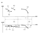
図2(a)は走行中または停止中の車両により生じるオクルージョンの発生範囲を示す、センサの検知範囲の平面図であり、図2(b)はセンサの検知範囲の側面図である。
センサ2は、道路上を走行中または停止中の車両を検知するために、車両よりも上方に設置され、斜め下方へ向けてレーダ波を放射するようにセンサ2の送信アンテナの向きが調整され、その結果、センサ2の検知範囲200は、交差点の手前から道路上に沿って所定の距離離れたところまでを含む。この場合、車両211の後方の領域201では、レーダ波が車両211によって遮られるため、センサ2は、その領域201内に位置する車両212を検知できない。すなわち、領域201においてオクルージョンが発生している。そして車両211が大きいほど、センサ2が車両を検知できない領域も広くなり、場合によっては、領域201の長さは約40mにもなる。そして停止中の車両の列の最後尾が領域201内に位置すると、センサ2は、車両の列の最後尾に位置する車両を検知できない。
しかし、領域201よりもさらに後方の領域202にはレーダ波が届くので、センサ2は、領域202内に位置する車両213を検知できる。そして車両213が停止中の車両の列の最後尾に達すると、車両213も停車する。そのため、車両213の挙動は、車両の列の最後尾の位置を特定するために利用できる。
そこで、車列長測定装置1は、センサ2の検知範囲内で、最も前方を走行する車両を検知し、その車両の挙動に基づいて車列長を求める。
FIG. 2A is a plan view of the detection range of the sensor showing the generation range of occlusion caused by the running or stopped vehicle, and FIG. 2B is a side view of the detection range of the sensor.
The sensor 2 is installed above the vehicle in order to detect a vehicle running or stopped on the road, and the direction of the transmission antenna of the sensor 2 is adjusted so as to radiate a radar wave obliquely downward. As a result, the
However, since the radar wave reaches the
Therefore, the vehicle train length measuring device 1 detects the vehicle traveling in the forefront within the detection range of the sensor 2, and obtains the vehicle train length based on the behavior of the vehicle.
センサインターフェース部11は、車列長測定装置1をセンサ2と接続するためのインターフェース回路を有する。このインターフェース回路は、例えば、RS-232Cまたはユニバーサルシリアルバスといったシリアル通信規格に準拠した回路、あるいは、イーサネット(登録商標)に準拠した回路とすることができる。そしてセンサインターフェース部11は、センサ2からセンサ信号を受け取る度に、そのセンサ信号を制御部15へ渡す。
The
信号機インターフェース部12は、車列長測定装置1を信号機(図示せず)と接続するためのインターフェース回路を有する。このインターフェース回路は、例えば、RS-232Cまたはユニバーサルシリアルバスといったシリアル通信規格に準拠した回路、あるいは、イーサネット(登録商標)に準拠した回路とすることができる。そして信号機インターフェース部12は、センサ2の近傍に設置され、センサ2の検知範囲に含まれる道路上の車両の通行を規制する信号機から、信号が切り替わるタイミングを表すタイミング情報を取得する。あるいは、信号機インターフェース部12は、制御部15から受け取った、車列長の測定値を信号機へ出力する。
The traffic signal interface unit 12 includes an interface circuit for connecting the vehicle train length measuring device 1 to a traffic signal (not shown). This interface circuit can be, for example, a circuit compliant with a serial communication standard such as RS-232C or universal serial bus, or a circuit compliant with Ethernet (registered trademark). The traffic signal interface unit 12 is installed in the vicinity of the sensor 2 and acquires timing information indicating the timing at which the signal is switched from a traffic signal that restricts the passage of vehicles on the road included in the detection range of the sensor 2. Alternatively, the traffic signal interface unit 12 outputs the measured value of the vehicle train length received from the
記憶部13は、例えば、読み書き可能な半導体メモリ回路と、読み出し専用の半導体メモリ回路とを有する。そして記憶部13は、車列長を測定するために用いられ、制御部15上で動作するコンピュータプログラムを記憶する。また記憶部13は、車列長を測定するために用いられる様々なデータ、例えば、センサ2から受け取ったセンサ信号、センサ信号に基づいて検知された車両の追跡情報などを記憶する。
The
出力部14は、車列長測定装置1を、他の機器、例えば、交通管理システムと接続するためのインターフェース回路を有する。このインターフェース回路は、例えば、イーサネット(登録商標)に準拠した回路とすることができる。そして出力部14は、制御部15から受け取った、車列長を他の機器へ出力する。
The output unit 14 includes an interface circuit for connecting the vehicle train length measuring device 1 to another device, for example, a traffic management system. This interface circuit can be a circuit that complies with, for example, Ethernet (registered trademark). Then, the output unit 14 outputs the vehicle train length received from the
制御部15は、車列長測定装置1全体を制御する。また制御部15は、センサ2から受け取ったセンサ信号に基づいて、センサ2の検知範囲内の道路上に停止している車両の列の長さを求める。そのために、制御部15は、少なくとも一つのプロセッサ、タイマ及び周辺回路を有する。
The
図3は、制御部15の機能ブロック図である。制御部15は、車両検知部21と、基準加速度算出部22と、減速判定部23と、停止位置推定部24と、車列長推定部25と、車列長調整部26とを有する。制御部15が有するこれらの各部は、制御部15が有するプロセッサ上で実行されるコンピュータプログラムによって実現される機能モジュールである。あるいは、制御部15が有するこれらの各部は、それぞれ、別個の回路として車列長測定装置1に実装されてもよい。
FIG. 3 is a functional block diagram of the
車両検知部21は、センサ2から制御部15がセンサ信号を受け取る度に、そのセンサ信号に基づいて、センサ2の検知範囲内を走行中または停車中の車両を検知する。そして車両検知部21は、検知した車両ごとに、その検知時刻における車両の位置及び速度を求める。
例えば、車両検知部21は、センサ信号に含まれる複数の位置のそれぞれについて、反射波の信号強度と検知すべき物体が存在しないときの信号強度に相当する閾値とを比較する。そして車両検知部21は、その信号強度が閾値よりも大きい位置に車両が存在すると判定する。そして車両検知部21は、車両が検知された位置に対応する速度を検知された車両の速度とする。
Each time the
For example, the
また車両検知部21は、検知された車両を追跡する。車両検知部21は、例えば、所定回数前に取得されたセンサ信号に基づいて検知された車両の位置から、その検知された車両の速度に最新のセンサ信号取得時までの経過時間を乗じた距離を減算することで、最新のセンサ信号取得時のその車両の位置を推定する。あるいは、車両検知部21は、後述する車両の挙動モデル(例えば、等加速度運動モデル)に従って、過去のセンサ信号に基づいて検知された車両の最新のセンサ信号取得時の位置を推定してもよい。なお、車両検知部21は、所定回数前に取得されたセンサ信号に基づいて複数台の車両が検知されている場合には、車両ごとに最新のセンサ信号取得時のその車両の位置を推定する。そして車両検知部21は、最新のセンサ信号に基づいて検知された車両の位置と最も近い、車両の推定位置を特定する。そして車両検知部21は、最新のセンサ信号に基づいて検知された車両が、特定された推定位置に対応する車両と同一であると判定する。
The
なお、車両検知部21は、車両の挙動モデルに従って、過去のセンサ信号に基づいて検知された車両の最新のセンサ信号取得時の位置及び速度を推定してもよい。この場合には、車両検知部21は、最新のセンサ信号に基づいて検知された車両は、その車両の位置及び速度と最も近い、推定位置及び推定速度に対応する車両と同一であると判定する。なお、車両検知部21は、最新のセンサ信号に基づいて検知された車両の位置から所定範囲内、及びその車両の位置よりも遠方に、過去のセンサ信号に基づいて検知された車両の推定位置がない場合、新たな車両が検知されたと判定する。そして車両検知部21は、新たに検知された車両に、既に検知されている他の車両と区別するための識別番号を割り当てる。
In addition, the
車両検知部21は、検知された車両ごとに、割り当てた識別番号とともに、センサ信号取得時の時刻、車両の位置及び速度の組を追跡情報として記憶部13に記憶する。車両が検知されている間、センサ信号が取得される度に求められた、センサ信号取得時の時刻、車両の位置及び速度の組がその車両の追跡情報に追加される。
For each detected vehicle, the
また車両検知部21は、検知されている車両のうち、車列長を推定するために注目する車両を決定する。本実施形態では、車列長測定装置1は、車列の最後尾に達しようとする車両の挙動に基づいて車列長を推定する。そこで車両検知部21は、速度が0でない、センサ2に接近中の車両のうちで最もセンサ2に近い車両、すなわち、停車中の車列よりも後方に位置する車両のうちで先頭を走行中の車両を、各車両の追跡情報に含まれる位置及び速度に基づいて特定する。そして車両検知部21は、その特定された車両を注目車両とする。そして車両検知部21は、注目車両の追跡情報に注目フラグを含める。
Moreover, the
さらに車両検知部21は、注目フラグが設定された車両、すなわち注目車両の追跡情報に含まれる、最新の時刻における速度が例えば5km/h以下となると、その注目車両は停止したと判定する。あるいは、後述するように、停止位置推定部24により推定された注目車両の停止位置に注目車両が達したと推定される時刻になると、車両検知部21は、注目車両は停止したと判定してもよい。そして車両検知部21は、停止した注目車両の追跡情報から注目フラグを消去する。
Furthermore, the
さらに、車両検知部21は、既に検知されている車両が、一定期間に渡って検知できなくなったとき、その車両はセンサ2の検知範囲から外れたと判定し、その車両に関する追跡情報を記憶部13から消去する。あるいは、車両検知部21は、既に検知されている車両が停止してから、あるいは、停止したと推定される時刻から所定期間を経過した後に、その車両の追跡情報を記憶部13から消去してもよい。所定期間は、例えば、車列長を求める道路に向けられた信号機の信号周期に設定される。
Further, when the vehicle that has already been detected cannot be detected for a certain period of time, the
センサ2の検知範囲内の道路が坂道である場合には、その道路を走行している車両が停止しようとしなくても、加速または減速することがある。そのため、センサ2の検知範囲内にいる車両が減速していても、その車両が停止しようとしているとは限らないことがある。一方、信号機が青信号を示している期間、すなわち、信号機がセンサ2へ向かって接近する方向の移動を許可する期間内であれば、センサ2の検知範囲内を走行中の車両は停止せずにその信号機が設置された交差点を通過しようとしていると推定される。 When the road within the detection range of the sensor 2 is a slope, the vehicle traveling on the road may accelerate or decelerate even if the vehicle does not stop. Therefore, even if the vehicle in the detection range of the sensor 2 is decelerating, the vehicle may not always stop. On the other hand, if the traffic light indicates a green signal, that is, within a period during which the traffic light is permitted to move in the direction approaching the sensor 2, the vehicle traveling within the detection range of the sensor 2 is not stopped. It is presumed that the traffic light is about to pass through the installed intersection.
そこで、基準加速度算出部22は、信号機から取得したタイミング情報に基づいて、青信号期間を特定する。基準加速度算出部22は、その特定された青信号期間が終了した直後に、その青信号期間内に検知された各車両の速度変化から、各車両の加速度の代表値を求める。そして基準加速度算出部22は、その加速度の代表値を、センサ2の検知範囲内を走行中の車両が停止するために減速しているか否かを判定するための基準となる基準加速度とする。
Therefore, the reference
例えば、基準加速度算出部22は、青信号期間内に検知されている車両ごとに、追跡情報を参照して、連続する二つの時刻の組ごとに、各時刻の車両の速度間の差をその時刻の差で除することにより、その時刻の組における車両の加速度を求める。そして基準加速度算出部22は、各組の車両の加速度の平均値、最頻値または中央値をその車両の加速度とする。あるいは、基準加速度算出部22は、青信号の期間内に検知されている車両ごとに、追跡情報を参照して、その車両が検知されている各時刻の速度に基づいて最小二乗法を適用することにより、その車両の加速度を求める。そして基準加速度算出部22は、各車両の加速度の平均値、中央値あるいは最頻値を基準加速度Astdとして記憶部13に記憶する。
なお、最新の青信号期間内に検知された車両が1台もなければ、記憶部13は、その最新の青信号期間よりも前の青信号期間について求められた基準加速度Astdを保持する。また、基準加速度算出部22は、複数の青信号期間の何れかについて検知された車両についてそれぞれ加速度を求め、各車両の加速度の平均値、中央値あるいは最頻値を基準加速度Astdとしてもよい。
For example, the reference
Note that if there is no vehicle detected within the latest green signal period, the
また、基準加速度算出部22は、青信号期間中の後半期間についての車両の追跡情報のみを用いて基準加速度Astdを算出してもよい。これにより、赤信号から青信号に変わったときに、停止していた車両が加速を開始したときの加速度が基準加速度Astdに影響しなくなるので、基準加速度算出部22は、基準加速度Astdをより適切に決定できる。
また、センサ2が設置された交差点よりも先の交差点を起点とする車列のために、車両が減速する可能性がある。このような場合、基準加速度算出部22は、基準加速度Astdをより適切に決定するためには、先の交差点から離れた車両の追跡情報のみを用いることが好ましい。そこで基準加速度算出部22は、センサ2の検知範囲の中心よりも遠方において検知されている車両の追跡情報のみを用いて基準加速度Astdを求めてもよい。
Further, the reference
Further, the vehicle may be decelerated due to a vehicle train starting from an intersection ahead of the intersection where the sensor 2 is installed. In such a case, it is preferable that the reference
さらに、基準加速度算出部22は、減速判定閾値Athを決定し、記憶部13に記憶する。減速判定閾値Athは、基準加速度Astdに負の値を持つマージン値Amarginを加えた値である。マージン値Amarginは、例えば、車両が停止せずに走行しているときの車両の加速度のバラツキの幅に相当する値に設定される。例えば、基準加速度Astd算出時における、加速度の標準偏差をσとすれば、マージン値Amarginは、-2σ〜-σに相当する値に設定される。
Further, the reference
減速判定部23は、信号機が赤信号を示すことにより車両が交差点を通過することを禁止している期間、すなわち、信号機がセンサ2へ向かって接近する方向の移動を規制する移動規制期間を、信号機から受け取ったタイミング情報に基づいて特定する。そして減速判定部23は、移動規制期間中、すなわち、赤信号期間中、制御部15がセンサ2からセンサ信号を受け取って注目車両の追跡情報が更新される度に、その追跡情報に基づいて注目車両の位置及び速度の変化から、注目車両の加速度を求める。なお、減速判定部23は、基準加速度算出部22が各車両の加速度を求める処理と同様の処理を行って、注目車両の加速度を算出できる。減速判定部23は、求めた加速度を注目車両の追跡情報に追加する。
そして減速判定部23は、注目車両の加速度を求める度に、その注目車両の加速度を減速判定閾値Athと比較する。注目車両の加速度が減速判定閾値Athよりも低ければ、減速判定部23は、注目車両は停止するために減速していると判定する。
The
The
図4は、青信号期間に検出された各車両の加速度から求められる基準加速度Astd及び減速判定閾値Athと、赤信号期間に検出された注目車両の加速度との関係を表す図である。
図4において横軸は時間を表す。また上側のグラフの縦軸は、検知された車両の速度を表し、下側のグラフの縦軸は、検知された車両の加速度を表す。なお、車両が減速している場合、その車両の加速度は負の値となる。
上側のグラフにおける線401〜403は、それぞれ、青信号期間420において検知された個々の車両の速度の時間変化を表す。また下側のグラフにおける線411〜413は、それぞれ、線401〜403に対応する車両の加速度の時間変化を表す。基準加速度算出部22は、線411〜413に示された加速度の統計値、例えば、それらの加速度の平均値を基準加速度Astdとし、基準加速度Astdに負のマージン値Amarginを加えた値を減速判定閾値Athに設定する。
一方、上側のグラフにおける線404は、赤信号期間421において検知された注目車両の速度の時間変化を表す。また下側のグラフにおける線414は、注目車両の加速度の時間変化を表す。線414に示されるように、時刻t1において、注目車両の加速度は、減速判定閾値Athよりも低くなる。そこで、この例では、減速判定部23は、時刻t1において注目車両が停止するために減速していると判定する。
減速判定部23は、注目車両が停止するために減速していると判定すると、その旨を停止位置推定部24に通知する。
FIG. 4 is a diagram illustrating the relationship between the reference acceleration A std and deceleration determination threshold value A th obtained from the acceleration of each vehicle detected during the green signal period, and the acceleration of the vehicle of interest detected during the red signal period.
In FIG. 4, the horizontal axis represents time. The vertical axis of the upper graph represents the detected vehicle speed, and the vertical axis of the lower graph represents the detected vehicle acceleration. When the vehicle is decelerating, the acceleration of the vehicle is a negative value.
On the other hand, a
When the
停止位置推定部24は、注目車両の追跡情報及び車両の挙動を表すモデルに基づいて、注目車両の停止位置を推定する。車両の挙動を表すモデルは、例えば、等加速度運動モデルとすることができる。この場合、停止位置推定部24は、次式に従って、停止線を基準とした、注目車両の停止位置Lxを推定する。

なお、停止位置推定部24は、車両の挙動を表す他のモデル、例えば、Chandlerモデル、Newellモデル、車間時間一定モデルあるいは線形フィードバックモデルに従って、注目車両の推定停止位置Lxを求めてもよい。これらのモデルについては、例えば、宮本他、「速度調整操作モデルにおけるドライバー特性の解析」、生産研究、2007年、第59巻、第3号、p.201-204に開示されている。
Incidentally, the stop
停止位置推定部24は、注目車両が停止するか、信号が青に変わるタイミングまで、追跡情報が更新される度に、最新の追跡情報に基づいて注目車両の推定停止位置Lxを更新してもよい。
また停止位置推定部24は、注目する車両が、注目車両よりも前に位置する車両によってセンサ2により検知できなくなった場合、その検知不能となった直前の時刻において求められた推定停止位置Lxを、最終的な推定停止位置とする。これにより、停止位置推定部24は、オクルージョンが生じていても、注目する車両の停止位置を推定できる。
Stop
Further, when the vehicle of interest cannot be detected by the sensor 2 due to the vehicle positioned before the vehicle of interest, the stop
車列長推定部25は、注目車両の推定停止位置Lxに基づいて、一時的に停止している車両の列の長さを推定する。一般的に、走行中の車両が停止している車両の列の最後尾に達した場合、衝突を避けるために、その走行中の車両は、列の最後尾に停車している車両との間にある程度の車間距離を空けて停止する。そこで車列長推定部25は、次式に示されるように、注目車両の推定停止位置Lxから停車時の車間距離の推定値Dwを引いた値を車列長Lとする。停車時の車間距離の推定値Dwは、例えば、5m〜10mに設定される。
図5は、注目車両の推定停止位置と、車列長との関係を示す図である。車列の先頭は、センサ2から距離Ds離れた位置にある停止線501である。そして、注目車両502が時刻t1において、位置xにて検知されているとすると、注目車両502は、停止するまでに、位置xから距離ΔSだけ進んだ位置Lxに停車すると推定される。したがって、車列長Lは、Lxから停車時の車間距離Dwを減じた値となる。
FIG. 5 is a diagram illustrating the relationship between the estimated stop position of the vehicle of interest and the vehicle train length. The head of the vehicle train is
なお、車列長推定部25は、減速判定部23により注目車両は減速していないと判定された場合、すなわち、注目車両の加速度が減速判定閾値Ath以上であった場合、車列長の推定を行わない。以降同様に、車列長推定部25は、減速判定部23による、センサ2から次に受け取ったセンサ信号に基づいた注目車両の加速度と減速判定閾値Athとの比較結果に応じて、車列長を推定するか、またはその推定を保留する。
なお、減速判定部23により注目車両は減速したと判定される前に、例えば、注目車両がオクルージョンが発生している領域に入ることで注目車両が検知されなくなった場合、車列長推定部25は、車列長を、一つ前の車両について求めた車列長としてもよい。あるいは、車列長推定部25は、後述する車列長調整部26と同様の処理を行って、車列長を推定してもよい。
Note that traffic
In addition, before it is determined by the
車列長推定部25は、求めた車列長Lを記憶部13に記憶するとともに、出力部14を介して他の機器へ出力する。あるいは、車列長推定部25は、車列長Lを信号機インターフェース部12を介して信号機へ出力する。
The vehicle train
最後に注目車両とされた車両がセンサ2によって検知できなくなってから所定期間Twaitが経過しても、その最後の注目車両よりも後方を走行する車両がセンサ2によって検知されないことがある。この場合、車列長調整部26は、最後の注目車両に基づいて推定された車列長を、最後の注目車両が車列の最後尾に停車しているとして、車列長を調整する。所定期間Twaitは、例えば、最後に注目車両とされた車両が最後に検知された時刻から、等加速度で減速した場合にその車両が停止するまでに要する期間に設定され、例えば、次式により求められる。
車列長調整部26は、調整後の車列長L'を次式に従って求める。
The vehicle train
なお、車列長調整部26は、調整後の車列長L'を、(1)式に従って算出される、最後に検知された時刻において求められた注目車両の推定停止位置LxにDxを加えた値としてもよい。
Note that traffic
図6は、制御部15により実行される車列長測定処理の動作フローチャートである。制御部15は、センサ2からセンサ信号を取得する度に、この動作フローチャートに従って車列長測定処理を実行する。
制御部15の車両検知部21は、センサ信号から車両を検知する(ステップS101)。そして車両検知部21は、最新のセンサ信号に基づいて検知された車両の位置と、過去のセンサ信号に基づいて検知された車両の位置などを用いて、車両ごとの追跡情報を更新する。
制御部15は、信号機インターフェース部12を介して信号機から取得したタイミング情報に基づいて、青信号期間が終了したか否か判定する(ステップS102)。
青信号期間の終了直後である場合(ステップS102−Yes)、制御部15の基準加速度算出部22は、検知された各車両の追跡情報に基づいて、青信号期間中における各車両の速度変化から基準加速度Astdを求める(ステップS103)。さらに基準加速度算出部22は、基準加速度Astdに基づいて減速判定閾値Athを決定する。そして基準加速度算出部22は、基準加速度Astd及び減速判定閾値Athを記憶部13に記憶する。
FIG. 6 is an operation flowchart of the vehicle train length measurement process executed by the
The
The
If it is immediately after the end of the green signal period (step S102-Yes), the reference
青信号期間の終了直後でない場合(ステップS102−No)、あるいはステップS103の後、制御部15は、タイミング情報に基づいて、赤信号期間中か否か判定する(ステップS104)。赤信号期間中でなければ(ステップS104−No)、制御部15は、車列長を求めずに車列長測定処理を終了する。
If it is not immediately after the end of the green light period (step S102-No), or after step S103, the
一方、ステップS104において赤信号期間中であれば(ステップS104−Yes)、制御部15は、注目車両に設定されていない、車列よりも後方を走行中の車両を検知する前に待機時間Twaitが経過したか否か判定する(ステップS105)。車両検知部21が検知している走行中の車両のうちで注目車両に設定されていない車両がある場合(ステップS105−No)、制御部15の減速判定部23は、未注目の車両のうち、先頭を走行中の車両を注目車両に設定する。そして減速判定部23は、注目車両の追跡情報に基づいて、注目車両の加速度Aintを算出する(ステップS106)。減速判定部23は、注目車両の加速度Aintが減速判定閾値Athより小さいか否か判定する(ステップS107)。注目車両の加速度Aintが減速判定閾値Ath以上であれば(ステップS107−No)、減速判定部23は、注目車両は停止するために減速していないと判定する。この場合、制御部15は、車列長を求めずに車列長測定処理を終了する。
一方、注目車両の加速度Aintが減速判定閾値Athより低ければ(ステップS107−Yes)、減速判定部23は、注目車両は停止するために減速していると判定する。この場合、制御部15の停止位置推定部24は、注目車両の追跡情報に基づいて停止位置を推定する(ステップS108)。そして車列長推定部25は、注目車両の推定された停止位置から車間距離を減じることで車列長を推定する(ステップS109)。
On the other hand, if it is during the red signal period in step S104 (step S104-Yes), the
On the other hand, if the acceleration A int of the vehicle of interest is lower than the deceleration determination threshold A th (step S107—Yes), the
また、ステップS105において、注目車両に設定されていない車両を検知する前に待機時間Twaitが経過した場合(ステップS105−Yes)、制御部15の車列長調整部26は、直前の注目車両の停止位置に基づいて推定された車列長に車間距離及び車両の長さを加算することで車列長を更新する(ステップS110)。
ステップS109またはS110の後、制御部15は、車列長測定処理を終了する。
In addition, in step S105, when the waiting time T wait has elapsed before detecting a vehicle that is not set as the vehicle of interest (step S105-Yes), the vehicle train
After step S109 or S110, the
以上に説明してきたように、この車列長測定装置は、車両の進行方向と対向して設置されたセンサを用いて停止している車両の列の長さを測定する。そのため、この車列長測定装置は、既存のセンサを利用できる。またこの車列長測定装置は、オクルージョンが生じている領域よりも後方を走行している車両の挙動に基づいて、その車両が停止する位置を推定するので、オクルージョンが生じていても車両の列の長さを測定できる。 As described above, this vehicle train length measuring apparatus measures the length of a train of vehicles that are stopped using a sensor that is installed facing the traveling direction of the vehicle. Therefore, this vehicle train length measuring device can use an existing sensor. Further, since this vehicle train length measuring device estimates the position where the vehicle stops based on the behavior of the vehicle traveling behind the region where the occlusion occurs, the train of vehicles Can be measured.
なお、本発明は上記の実施形態に限定されるものではない。一つの変形例によれば、センサは、画像センサであってもよい。この場合、センサは、車列長を測定しようとする道路及びその道路上の車両を一定の周期ごとに撮影して画像を生成する。そしてセンサは、画像を生成する度に、その画像を制御部に渡す。
制御部の車両検知部は、センサから受け取った画像に写った車両を検出することにより、道路上の車両を検知する。そのために、車両検知部は、例えば、センサから受け取った画像と、記憶部に予め記憶されている、道路上を走行する車両が存在しない場合にその道路を撮影した背景画像との間で背景差分処理を実行する。そして車両検知部は、背景差分処理によって得られた差分画像上で所定の閾値以上の画素値の絶対値を持つ画素の集合を、車両が写っている領域として検出する。あるいは、車両検知部は、車両を表す少なくとも一つのテンプレートと画像との間でテンプレートマッチングを行って正規化相互相関値を求め、その正規化相互相関値が予め定められた値以上となった画像上の領域に、車両が写っていると判定する。
そして、画像上の位置と道路上の位置は、一対一に対応するので、車両検知部は、車両が検知された画像上の領域の重心位置に基づいて、センサからその検知された車両までの距離を求めることができる。
センサとしてレーダ検知器が用いられる場合、注目する車両の一部が他の車両に隠れると、その隠れた部分の大きさに応じて反射波の信号強度が低下するので、車両検知部は、注目する車両を検知し難くなる。一方、センサとして画像センサが用いられる場合、注目する車両の一部が他の車両に隠れている場合でも、車両検知部は、画像上でその注目する車両の隠されていない部分を検出することで、その車両を検知できる。そのため、センサとして画像センサを利用することにより、車列長測定装置は、オクルージョンが生じる領域を小さくできる。
In addition, this invention is not limited to said embodiment. According to one variant, the sensor may be an image sensor. In this case, the sensor shoots the road on which the train length is to be measured and the vehicles on the road at regular intervals to generate an image. And whenever a sensor produces | generates an image, it passes the image to a control part.
The vehicle detection unit of the control unit detects a vehicle on the road by detecting the vehicle shown in the image received from the sensor. Therefore, the vehicle detection unit, for example, the background difference between the image received from the sensor and the background image that is stored in advance in the storage unit and that images the road when there is no vehicle traveling on the road. Execute the process. Then, the vehicle detection unit detects a set of pixels having an absolute value of pixel values equal to or greater than a predetermined threshold on the difference image obtained by the background difference process as a region where the vehicle is reflected. Alternatively, the vehicle detection unit obtains a normalized cross-correlation value by performing template matching between at least one template representing the vehicle and an image, and the normalized cross-correlation value is equal to or greater than a predetermined value. It is determined that the vehicle is reflected in the upper area.
And since the position on the image and the position on the road correspond one-to-one, the vehicle detection unit detects the vehicle from the sensor to the detected vehicle based on the position of the center of gravity of the area on the image where the vehicle is detected. The distance can be determined.
When a radar detector is used as a sensor, if a part of the vehicle of interest is hidden behind another vehicle, the signal strength of the reflected wave is reduced according to the size of the hidden portion. It becomes difficult to detect the vehicle to be. On the other hand, when an image sensor is used as the sensor, the vehicle detection unit detects an unhidden portion of the vehicle of interest on the image even when a portion of the vehicle of interest is hidden behind another vehicle. Thus, the vehicle can be detected. Therefore, by using an image sensor as the sensor, the vehicle train length measuring device can reduce the area where the occlusion occurs.
さらに他の変形例によれば、センサは、パルス圧縮方式または二周波連続波(continuous wave、CW)方式に従ったレーダ装置であってもよい。この場合、制御部は、一定の周期ごとに、センサから、所定の距離間隔で設定された複数の位置のそれぞれについて反射波の信号強度を含むセンサ信号を受け取る。そして車両検知部は、反射波の信号強度が所定の閾値以上である距離に車両が存在すると判定する。この場合、車両検知部は、例えば、最新のセンサ信号において検知された車両の現在位置と、1回前に取得したセンサ信号において検知された車両の過去位置とを比較する。そして車両検知部は、現在位置よりも遠方で、かつ現在位置に最も近い過去位置にいる車両と、現在位置にいる車両が同一の車両であると判定することで、車両ごとの追跡情報を更新する。さらに車両検知部は、車両ごとに、現在位置と過去位置間の距離をセンサ信号の取得周期で割ることにより、現在位置における車両の速度を求める。 According to still another modification, the sensor may be a radar device according to a pulse compression method or a continuous frequency (CW) method. In this case, the control unit receives a sensor signal including the signal intensity of the reflected wave at each of a plurality of positions set at a predetermined distance interval from the sensor at regular intervals. And a vehicle detection part determines with a vehicle existing in the distance where the signal strength of a reflected wave is more than a predetermined threshold value. In this case, for example, the vehicle detection unit compares the current position of the vehicle detected in the latest sensor signal with the past position of the vehicle detected in the sensor signal acquired one time before. Then, the vehicle detection unit updates the tracking information for each vehicle by determining that the vehicle at the past position closest to the current position and the vehicle at the current position is far from the current position and the vehicle at the current position is the same vehicle. To do. Further, the vehicle detection unit obtains the speed of the vehicle at the current position by dividing the distance between the current position and the past position by the sensor signal acquisition cycle for each vehicle.
さらに他の変形例によれば、減速判定閾値Athは、予め定められた値、例えば、-5km/sec2であってもよい。この場合、減速判定閾値Athは、予め記憶部に記憶される。そのため、制御部は、基準加速度算出部の機能を有さなくてもよい。
例えば、車列長を測定しようとする交差点近傍の道路が平坦であり、かつ、その交差点に設置された信号機以外に、車両を停止させる要因となるものが存在しない場合には、その交差点を通過する車両は一定の速度を保つと推定される。したがって、この場合には、制御部が、一定以上減速している車両は停止すると推定されるので、減速判定閾値Athも、基準加速度に依存せずに決定できる。
According to still another modification, the deceleration determination threshold value A th may be a predetermined value, for example, −5 km / sec 2 . In this case, the deceleration determination threshold Ath is stored in advance in the storage unit. Therefore, the control unit may not have the function of the reference acceleration calculation unit.
For example, if the road near the intersection where the train length is to be measured is flat and there are no traffic lights installed at the intersection that cause the vehicle to stop, pass through the intersection. It is estimated that a vehicle that keeps a constant speed. Therefore, in this case, since the control unit is estimated to stop the vehicle that decelerates more than a certain value, the deceleration determination threshold Ath can also be determined without depending on the reference acceleration.
さらに他の変形例によれば、減速判定部は、青信号期間中でも注目車両が減速しているか否かを判定してもよい。さらに、停止位置推定部及び車列長推定部は、青信号期間中でも注目車両の停止位置を推定し、その推定停止位置に応じて車列長を推定してもよい。これにより、特に、渋滞によって青信号期間中でも一時停止中の車両の列が形成される場合に、車列長測定装置は、その車列長を測定できる。またこの変形例では、車列長測定装置において、信号機インターフェース部は省略されてもよい。
また、車列長測定装置は、注目車両の加速度を求める度に、その加速度を減速判定閾値と比較することなく、注目車両の停止位置を推定し、その推定停止位置に応じて車列長を推定してもよい。この場合には、推定された注目車両の停止位置が、想定される車列の先頭の位置、例えば、停止線の位置よりも前方となる場合、車列長推定部は、車列は無いと判定する。一方、推定された注目車両の停止位置が想定される車列の先頭の位置よりも後方であれば、車列長推定部は、上記の実施形態と同様に車列長を推定すればよい。
さらに、上記の実施形態またはその変形例による車列長測定装置は、交差点に限らず、渋滞などによって車列が形成されるところ、例えば、高速道路の渋滞の頻発ポイントに設置されてもよい。
According to still another modification, the deceleration determination unit may determine whether or not the vehicle of interest is decelerating even during the green light period. Furthermore, the stop position estimation unit and the vehicle train length estimation unit may estimate the stop position of the vehicle of interest even during the green light period, and may estimate the vehicle train length according to the estimated stop position. As a result, the vehicle train length measuring device can measure the vehicle train length, particularly when a train of suspended vehicles is formed even during a green light period due to traffic jams. In this modification, the traffic signal interface unit may be omitted in the vehicle train length measuring device.
Further, every time the vehicle train length measuring device obtains the acceleration of the vehicle of interest, it estimates the stop position of the vehicle of interest without comparing the acceleration with the deceleration determination threshold value, and determines the vehicle train length according to the estimated stop position It may be estimated. In this case, when the estimated stop position of the vehicle of interest is ahead of the assumed head position of the vehicle train, for example, the position of the stop line, the vehicle train length estimation unit determines that there is no vehicle train. judge. On the other hand, if the estimated stop position of the vehicle of interest is behind the assumed head position of the vehicle train, the vehicle train length estimation unit may estimate the vehicle train length as in the above embodiment.
Furthermore, the vehicle train length measuring device according to the above-described embodiment or its modification is not limited to an intersection, and may be installed at a frequent traffic congestion point on a highway, for example, where a vehicle train is formed by traffic jams.
また、上記の実施形態または変形例による制御部の機能をコンピュータに実現させる命令を有するコンピュータプログラムは、磁気記録媒体、光記録媒体あるいは不揮発性の半導体メモリといった、記録媒体に記録された形で提供されてもよい。 A computer program having instructions for causing a computer to realize the functions of the control unit according to the above-described embodiment or modification is provided in a form recorded on a recording medium such as a magnetic recording medium, an optical recording medium, or a nonvolatile semiconductor memory. May be.
上記の実施形態またはその変形例による車列長測定装置における車列長の測定結果は、様々なシステムにおいて利用される。例えば、その測定結果は、信号制御システムが信号を切り替えるタイミングを制御したり、あるいは運転支援システムにおいて衝突防止の警告を行うか否かの判定に利用される。 The measurement result of the vehicle train length in the vehicle train length measurement device according to the above-described embodiment or its modification is used in various systems. For example, the measurement result is used to control whether the signal control system switches the signal, or to determine whether or not to issue a collision prevention warning in the driving support system.
図7は、上記の実施形態またはその変形例による車列長測定装置が組み込まれた路側器の概略構成図である。
路側器30は、例えば、交差点の近傍に設置される。そして路側器30は、車両に搭載された車載通信機と無線通信可能となっている。
路側器30は、例えば、その交差点に接続される道路上に停車中の車両の列の長さを検知する。そして路側器30は、その停車中の車両の列よりも後方を走行中の車両の停止位置を推定し、その推定停止位置と車両の列の長さとを比較することで、走行中の車両が停車中の最後尾の車両に衝突する危険性があるか否かを判定する。そして路側器30は、衝突の危険性があると判定した場合、その走行中の車両に搭載された車載通信機へ、警告信号を送信する。
そのために、路側器30は、センサインターフェース部31と、信号機インターフェース部32と、記憶部33と、制御部34と、通信制御部35と、変調部36と、アンテナ37とを有する。
FIG. 7 is a schematic configuration diagram of a roadside device in which the vehicle train length measuring device according to the above-described embodiment or its modification is incorporated.
The
The
For this purpose, the
このうち、センサインターフェース部31、信号機インターフェース部32、記憶部33及び制御部34は、上記の実施形態またはその変形例による車列長測定装置のセンサインターフェース部、信号機インターフェース部、記憶部及び制御部に対応する。すなわち、図7において点線で囲まれた部分が車列長測定装置に相当する。
そしてセンサインターフェース部31は、交差点の近傍に設けられたレーダ装置またはカメラといったセンサからセンサ信号を受信し、制御部34はそのセンサ信号に基づいて注目車両を決定し、注目車両の停止位置を推定することで車列長を求める。
また制御部34は、一つ前の注目車両に基づいて求めた車列長よりも、現在の注目車両に基づいて求めた車列長の方が短い場合には、その注目車両が車列の最後尾に衝突する可能性があると判定する。そしてこの場合、制御部34は、衝突する可能性があることを示す警告情報を生成する。
Among these, the
The
Further, when the vehicle train length obtained based on the current vehicle of interest is shorter than the vehicle train length obtained based on the previous vehicle of interest, the
通信制御部35は、少なくとも一つのプロセッサと、メモリ回路とを有する。そして通信制御部35は、路側器30の通信可能範囲内に存在する車載通信機との間で通信チャネルを設定する。そして通信制御部35は、制御部34から警告情報を受け取ると、その警告情報を含む通知信号を生成する。通信制御部35は、通知信号に対してターボ符号化処理などの誤り訂正符号化処理を実行する。そして通信制御部35は、誤り訂正符号化された通知信号に対して、例えば、直交周波数分割多重(Orthogonal Frequency Division Multiplex、OFDM)方式といった所定の多重化方式に従って多重化する。通信制御部35は、多重化された通知信号を変調部36へ出力する。
The
変調部36は、通信制御部35から受け取った通知信号をアナログ化する。そして変調部36は、アナログ化された通知信号を、無線周波数を持つ搬送波に重畳することにより無線信号を生成し、その無線信号を電力増幅器により増幅する。そして変調部36は、増幅された無線信号をアンテナ37を介して車載通信機(図示せず)へ向けて出力する。
このように、路側器30は、停車中の車両の列に衝突する可能性の有る車両に対して、警告を発することができる。
The
In this way, the
ここに挙げられた全ての例及び特定の用語は、読者が、本発明及び当該技術の促進に対する本発明者により寄与された概念を理解することを助ける、教示的な目的において意図されたものであり、本発明の優位性及び劣等性を示すことに関する、本明細書の如何なる例の構成、そのような特定の挙げられた例及び条件に限定しないように解釈されるべきものである。本発明の実施形態は詳細に説明されているが、本発明の精神及び範囲から外れることなく、様々な変更、置換及び修正をこれに加えることが可能であることを理解されたい。 All examples and specific terms listed herein are intended for instructional purposes to help the reader understand the concepts contributed by the inventor to the present invention and the promotion of the technology. It should be construed that it is not limited to the construction of any example herein, such specific examples and conditions, with respect to showing the superiority and inferiority of the present invention. Although embodiments of the present invention have been described in detail, it should be understood that various changes, substitutions and modifications can be made thereto without departing from the spirit and scope of the present invention.
1 車列長測定装置
2 センサ
11 センサインターフェース部
12 信号機インターフェース部
13 記憶部
14 出力部
15 制御部
21 車両検知部
22 基準加速度算出部
23 減速判定部
24 停止位置推定部
25 車列長推定部
26 車列長調整部
30 路側器
31 センサインターフェース部
32 信号機インターフェース部
33 記憶部
34 制御部
35 通信制御部
36 変調部
37 アンテナ
DESCRIPTION OF SYMBOLS 1 Vehicle train length measuring apparatus 2
Claims (7)
前記検知された車両のうち、前記センサに接近中でかつ最も近くを走行中の第1の車両の位置及び速度の変化から、当該第1の車両の停止位置を推定する停止位置推定部と、
前記推定された停止位置よりも車間距離の推定値だけ前記センサに近い位置を停車中の車両の列の最後尾と推定することで、該停車中の車両の列の長さを求める車列長推定部と、
を有する車列長測定装置。 A vehicle detection unit that detects a vehicle based on a sensor signal acquired from a sensor installed opposite to the front surface of the vehicle within a predetermined detection range, and determines the position and speed of the detected vehicle;
Among the detected vehicles, a stop position estimating unit that estimates a stop position of the first vehicle from changes in the position and speed of the first vehicle that is approaching the sensor and traveling closest to the sensor;
A train queue length for determining the length of the trained vehicle row by estimating a position closer to the sensor by an estimated value of the inter-vehicle distance than the estimated stop position as the tail of the trained vehicle train An estimation unit;
A vehicle train length measuring device.
前記車列長推定部は、前記第1の車両が減速していると判定された場合に前記第1の車両の推定された停止位置に基づいて停車中の車両の列の長さを求める、請求項1に記載の車列長測定装置。 A deceleration determination unit that obtains an acceleration of the first vehicle from changes in the position and speed of the first vehicle and determines that the first vehicle is decelerating when the acceleration is lower than a deceleration determination threshold. Further comprising
The vehicle train length estimation unit obtains the length of the train of stopped vehicles based on the estimated stop position of the first vehicle when it is determined that the first vehicle is decelerating. The vehicle train length measuring device according to claim 1.
前記停止位置推定部は、前記タイミング情報に基づいて、前記信号機が前記道路上を前記センサへ向かって接近する方向の移動を規制する移動規制期間を特定し、当該期間内に限り、前記第1の車両の停止位置を推定する、請求項2に記載の車列長測定装置。 A traffic signal interface unit that acquires timing information indicating a timing at which the signal of the traffic signal is switched from a traffic signal that restricts traffic of a vehicle on a road included in the predetermined detection range;
The stop position estimating unit specifies a movement restriction period for restricting movement of the traffic light in a direction approaching the sensor on the road based on the timing information, and the first position is limited to the first period. The vehicle train length measuring device according to claim 2, wherein a stop position of the vehicle is estimated.
前記検知された車両のうち、前記センサに接近中でかつ最も近くを走行中の第1の車両の位置及び速度の変化から、当該第1の車両の停止位置を推定し、
前記推定された停止位置よりも車間距離の推定値だけ前記センサに近い位置を停車中の車両の列の最後尾と推定することで、該停車中の車両の列の長さを求める、
ことを含む車列長測定方法。 Detecting a vehicle based on a sensor signal acquired from a sensor installed opposite to the front surface of the vehicle within a predetermined detection range, and determining the position and speed of the detected vehicle;
From the detected vehicles, the stop position of the first vehicle is estimated from changes in the position and speed of the first vehicle that is approaching and is closest to the sensor,
By estimating the position closer to the sensor by the estimated value of the inter-vehicle distance than the estimated stop position as the tail of the train of vehicles being stopped, the length of the train of vehicles being stopped is obtained.
A method for measuring the length of a train including the above.
前記検知された車両のうち、前記センサに接近中でかつ最も近くを走行中の第1の車両の位置及び速度の変化から、当該第1の車両の停止位置を推定し、
前記推定された停止位置よりも車間距離の推定値だけ前記センサに近い位置を停車中の車両の列の最後尾と推定することで、該停車中の車両の列の長さを求める、
ことをコンピュータに実行させる車列長測定用コンピュータプログラム。 Detecting a vehicle based on a sensor signal acquired from a sensor installed opposite to the front surface of the vehicle within a predetermined detection range, and determining the position and speed of the detected vehicle;
From the detected vehicles, the stop position of the first vehicle is estimated from changes in the position and speed of the first vehicle that is approaching and is closest to the sensor,
By estimating the position closer to the sensor by the estimated value of the inter-vehicle distance than the estimated stop position as the tail of the train of vehicles being stopped, the length of the train of vehicles being stopped is obtained.
A computer program for measuring a vehicle train length that causes a computer to execute the operation.
Priority Applications (5)
| Application Number | Priority Date | Filing Date | Title |
|---|---|---|---|
| JP2011175083A JP5741310B2 (en) | 2011-08-10 | 2011-08-10 | Train length measuring device, train length measuring method, and train length measuring computer program |
| EP12178089.4A EP2557551B1 (en) | 2011-08-10 | 2012-07-26 | Apparatus for measuring vehicle queue length, method for measuring vehicle queue length, and computer-readable recording medium storing computer program for measuring vehicle queue length |
| US13/561,740 US9361801B2 (en) | 2011-08-10 | 2012-07-30 | Apparatus for measuring vehicle queue length, method for measuring vehicle queue length, and computer-readable recording medium storing computer program for measuring vehicle queue length |
| KR1020120087303A KR101498765B1 (en) | 2011-08-10 | 2012-08-09 | Apparatus for measuring length of queued vehicles, method for measuring length of queued vehicles, and computer readable recording medium having computer program for measuring length of queued vehicles |
| KR1020150019353A KR101542032B1 (en) | 2011-08-10 | 2015-02-09 | Apparatus for measuring length of queued vehicles, method for measuring length of queued vehicles, and computer readable recording medium having computer program for measuring length of queued vehicles |
Applications Claiming Priority (1)
| Application Number | Priority Date | Filing Date | Title |
|---|---|---|---|
| JP2011175083A JP5741310B2 (en) | 2011-08-10 | 2011-08-10 | Train length measuring device, train length measuring method, and train length measuring computer program |
Publications (2)
| Publication Number | Publication Date |
|---|---|
| JP2013036932A JP2013036932A (en) | 2013-02-21 |
| JP5741310B2 true JP5741310B2 (en) | 2015-07-01 |
Family
ID=46924223
Family Applications (1)
| Application Number | Title | Priority Date | Filing Date |
|---|---|---|---|
| JP2011175083A Expired - Fee Related JP5741310B2 (en) | 2011-08-10 | 2011-08-10 | Train length measuring device, train length measuring method, and train length measuring computer program |
Country Status (4)
| Country | Link |
|---|---|
| US (1) | US9361801B2 (en) |
| EP (1) | EP2557551B1 (en) |
| JP (1) | JP5741310B2 (en) |
| KR (2) | KR101498765B1 (en) |
Families Citing this family (39)
| Publication number | Priority date | Publication date | Assignee | Title |
|---|---|---|---|---|
| JPWO2011125185A1 (en) * | 2010-04-07 | 2013-07-08 | トヨタ自動車株式会社 | Vehicle travel support device |
| WO2012144255A1 (en) * | 2011-04-21 | 2012-10-26 | 三菱電機株式会社 | Drive assistance device |
| US9209985B1 (en) * | 2013-01-31 | 2015-12-08 | Maritime Telecommunications Network Inc. | Association of diverse application logic across multiple distinct devices with priority bandwidth channel |
| JP6120166B2 (en) * | 2013-06-04 | 2017-04-26 | パナソニックIpマネジメント株式会社 | Vehicle stop determination result providing method, vehicle stop determination device, and vehicle stop determination system |
| JP5683663B1 (en) * | 2013-09-27 | 2015-03-11 | パナソニックIpマネジメント株式会社 | Residence time measuring device, residence time measuring system, and residence time measuring method |
| US10692370B2 (en) * | 2014-03-03 | 2020-06-23 | Inrix, Inc. | Traffic obstruction detection |
| CN103985251B (en) * | 2014-04-21 | 2016-03-02 | 东南大学 | A kind of method and system of vehicle queue length measuring and calculating |
| US9759812B2 (en) * | 2014-10-02 | 2017-09-12 | Trimble Inc. | System and methods for intersection positioning |
| US10366604B1 (en) * | 2014-12-12 | 2019-07-30 | Robert Joseph Bermudez | Taxi information system |
| GB2555029A (en) * | 2015-05-19 | 2018-04-18 | Wal Mart Stores Inc | Measurement system and method |
| US11087291B2 (en) * | 2015-11-24 | 2021-08-10 | Honda Motor Co., Ltd.. | Action planning and execution support device |
| EP3236446B1 (en) * | 2016-04-22 | 2022-04-13 | Volvo Car Corporation | Arrangement and method for providing adaptation to queue length for traffic light assist-applications |
| KR101677593B1 (en) * | 2016-07-14 | 2016-11-18 | 국방과학연구소 | Deceleration hysteresis measuring apparatus for soft-recovery system |
| CN106097730B (en) * | 2016-08-10 | 2018-08-21 | 青岛海信网络科技股份有限公司 | A kind of method of estimation of section vehicle queue length, apparatus and system |
| US10181263B2 (en) | 2016-11-29 | 2019-01-15 | Here Global B.V. | Method, apparatus and computer program product for estimation of road traffic condition using traffic signal data |
| CN106781542B (en) * | 2016-12-30 | 2020-01-31 | 迈锐数据(北京)有限公司 | vehicle queuing length detection system, method and device |
| CN106920403B (en) * | 2017-03-12 | 2019-10-29 | 浙江大学 | A kind of single-point self-adaptation control method based on array radar |
| CN107464427B (en) * | 2017-07-17 | 2019-09-10 | 东南大学 | A kind of queuing vehicle length detecting systems and method |
| US10825344B2 (en) * | 2018-02-01 | 2020-11-03 | GM Global Technology Operations LLC | System and method for forming a fleet and positioning vehicles in the fleet |
| JP7201340B2 (en) * | 2018-05-24 | 2023-01-10 | 株式会社Nttドコモ | Vehicle group determination device and vehicle group determination system |
| CN108806282B (en) * | 2018-06-01 | 2020-09-04 | 浙江大学 | Lane group maximum queuing length estimation method based on sample travel time information |
| CN109035814B (en) * | 2018-07-02 | 2021-04-09 | 福建榕基软件股份有限公司 | Automatic traffic light interval time adjusting method and system |
| CN109064098B (en) * | 2018-08-09 | 2021-11-23 | 圆通速递有限公司 | Vehicle dynamic scheduling method and system |
| CN110689738A (en) * | 2019-09-24 | 2020-01-14 | 北京地平线机器人技术研发有限公司 | Traffic signal lamp control method and device, storage medium and electronic equipment |
| CN110751826B (en) * | 2019-10-30 | 2021-07-06 | 浙江大华技术股份有限公司 | Vehicle queuing determination method and related device |
| CN112802325B (en) * | 2019-11-13 | 2023-06-27 | 阿波罗智联(北京)科技有限公司 | Vehicle queuing length detection method and device |
| CN111145566B (en) * | 2019-12-19 | 2022-04-01 | 南京理工大学 | Intelligent traffic light system and control method |
| CN111882858B (en) * | 2020-06-01 | 2022-05-20 | 重庆大学 | Multi-source data-based method for predicting queuing length of highway abnormal event |
| CN111696367B (en) * | 2020-06-11 | 2022-06-07 | 西安电子科技大学 | Multi-geomagnetic-sensor speed measurement system and speed measurement method thereof |
| CN112085950B (en) * | 2020-08-17 | 2021-10-29 | 西安电子科技大学 | Method and system for estimating traffic state discrimination index, storage medium and application |
| JP7157780B2 (en) | 2020-08-27 | 2022-10-20 | 本田技研工業株式会社 | Information presentation device for self-driving cars |
| US20240046784A1 (en) * | 2020-12-04 | 2024-02-08 | Viavi Solutions Inc. | Distributed acoustic sensing of traffic |
| CN112712694B (en) * | 2020-12-24 | 2023-05-05 | 重庆中信科信息技术有限公司 | Sporadic congestion recognition analysis method based on space-time analysis |
| CN112904838B (en) * | 2021-01-06 | 2021-11-26 | 北京科技大学 | Two-dimensional plane intelligent vehicle queue control method |
| CN112859062B (en) * | 2021-01-19 | 2023-11-24 | 巍泰技术(武汉)有限公司 | Vehicle queuing length detection method and system based on radar |
| US11935404B2 (en) * | 2021-03-24 | 2024-03-19 | Toyota Motor Engineering & Manufacturing North America, Inc. | Integrated congested mitigation for freeway non-recurring queue avoidance |
| CN115223353A (en) * | 2021-04-21 | 2022-10-21 | 北京航迹科技有限公司 | Method and device for positioning vehicles in fleet |
| CN113129595B (en) * | 2021-04-23 | 2022-06-10 | 山东金宇信息科技集团有限公司 | Traffic signal control method, equipment and medium for road intersection |
| DE102021005661A1 (en) | 2021-11-16 | 2022-02-03 | Daimler Ag | Vehicle radar for detecting columns ahead |
Family Cites Families (23)
| Publication number | Priority date | Publication date | Assignee | Title |
|---|---|---|---|---|
| JPH11110685A (en) * | 1997-10-08 | 1999-04-23 | Mitsubishi Electric Corp | Traffic control support system |
| DE19953008A1 (en) * | 1999-10-27 | 2001-05-03 | Johann F Hipp | Device for controlling the flow of traffic at an intersection, in particular for controlling traffic lights |
| JP2002150480A (en) * | 2000-11-15 | 2002-05-24 | Yazaki Corp | Traffic light control system |
| JP2002183887A (en) * | 2000-12-12 | 2002-06-28 | Nissan Motor Co Ltd | Vehicle departure informing device |
| KR100459476B1 (en) * | 2002-04-04 | 2004-12-03 | 엘지산전 주식회사 | Apparatus and method for queue length of vehicle to measure |
| US7860639B2 (en) * | 2003-02-27 | 2010-12-28 | Shaoping Yang | Road traffic control method and traffic facilities |
| US7821422B2 (en) * | 2003-08-18 | 2010-10-26 | Light Vision Systems, Inc. | Traffic light signal system using radar-based target detection and tracking |
| US7663505B2 (en) * | 2003-12-24 | 2010-02-16 | Publicover Mark W | Traffic management device and system |
| JP2007011557A (en) * | 2005-06-29 | 2007-01-18 | Nissan Motor Co Ltd | Traffic jam detection system, onboard information terminal, information center, and method for detecting traffic jam |
| JP4720457B2 (en) | 2005-11-22 | 2011-07-13 | アイシン・エィ・ダブリュ株式会社 | Vehicle driving support method and driving support device |
| KR101716873B1 (en) * | 2006-03-16 | 2017-03-15 | 엠.브루베이커 커티스 | System and method for obtaining revenue through the display of hyper-relevant advertising on moving objects |
| JP4743523B2 (en) * | 2006-03-22 | 2011-08-10 | 住友電気工業株式会社 | Prediction system for vehicle behavior at intersections |
| JP5003546B2 (en) * | 2007-06-07 | 2012-08-15 | 住友電気工業株式会社 | Traffic signal control system, traffic signal control device and method, and traffic index calculation device |
| US20090088916A1 (en) * | 2007-09-28 | 2009-04-02 | Honeywell International Inc. | Method and system for automatic path planning and obstacle/collision avoidance of autonomous vehicles |
| GB0802205D0 (en) * | 2008-02-06 | 2008-03-12 | Hatton Traffic Man Ltd | Traffic control system |
| EP2187369A3 (en) * | 2008-06-04 | 2012-03-28 | Roads and Traffic Authority of New South Wales | Traffic signals control system |
| CN102124505A (en) | 2008-06-13 | 2011-07-13 | Tmt服务和供应(股份)有限公司 | Traffic control system and method |
| JP5256923B2 (en) | 2008-08-11 | 2013-08-07 | 住友電気工業株式会社 | Signal queue information generation apparatus, computer program, and signal queue information generation method |
| US8279086B2 (en) * | 2008-09-26 | 2012-10-02 | Regents Of The University Of Minnesota | Traffic flow monitoring for intersections with signal controls |
| AU2009304571A1 (en) * | 2008-10-15 | 2010-04-22 | National Ict Australia Limited | Tracking the number of vehicles in a queue |
| JP5343637B2 (en) * | 2009-03-09 | 2013-11-13 | オムロン株式会社 | Signal control device |
| JP5439004B2 (en) * | 2009-03-30 | 2014-03-12 | 株式会社サイデン | Traffic jam detection device and program |
| WO2012068064A1 (en) * | 2010-11-15 | 2012-05-24 | Image Sensing Systems, Inc. | Hybrid traffic sensor system and associated method |
-
2011
- 2011-08-10 JP JP2011175083A patent/JP5741310B2/en not_active Expired - Fee Related
-
2012
- 2012-07-26 EP EP12178089.4A patent/EP2557551B1/en not_active Not-in-force
- 2012-07-30 US US13/561,740 patent/US9361801B2/en not_active Expired - Fee Related
- 2012-08-09 KR KR1020120087303A patent/KR101498765B1/en not_active IP Right Cessation
-
2015
- 2015-02-09 KR KR1020150019353A patent/KR101542032B1/en active IP Right Grant
Also Published As
| Publication number | Publication date |
|---|---|
| JP2013036932A (en) | 2013-02-21 |
| KR20150023612A (en) | 2015-03-05 |
| US9361801B2 (en) | 2016-06-07 |
| US20130041573A1 (en) | 2013-02-14 |
| EP2557551B1 (en) | 2017-05-17 |
| KR20130018161A (en) | 2013-02-20 |
| KR101542032B1 (en) | 2015-08-04 |
| EP2557551A1 (en) | 2013-02-13 |
| KR101498765B1 (en) | 2015-03-04 |
Similar Documents
| Publication | Publication Date | Title |
|---|---|---|
| JP5741310B2 (en) | Train length measuring device, train length measuring method, and train length measuring computer program | |
| JP5267517B2 (en) | Vehicle position estimation apparatus and vehicle position estimation program | |
| CN105984448A (en) | Autonomous emergency braking system and method of controlling the same | |
| JP5482670B2 (en) | Object detection device | |
| KR101319550B1 (en) | Apparatus for displaying car speed | |
| CN105637384A (en) | Method for classifying obstacles | |
| JP2019207654A (en) | Detection device and detection system | |
| JP2008299758A (en) | Vehicle driving support system, driving support device, vehicle and vehicle driving support method | |
| KR101979928B1 (en) | System and method for estimating distance of front vehicle | |
| KR101489886B1 (en) | System for controlling automatically a train using smart signal | |
| WO2018216066A1 (en) | Onboard apparatus, traveling assistance method and traveling assistance program | |
| KR101316306B1 (en) | Smart-cruise-control-system and method for controlling the same | |
| CN115497282B (en) | Information processing device, information processing method, and storage medium | |
| US20200369266A1 (en) | Signal processing apparatus, signal processing method, and program | |
| JP2004295620A (en) | Device for detecting possibility of vehicle collision | |
| TWI541151B (en) | System and method for detecting vehicle collision | |
| JP5783163B2 (en) | Target detection device | |
| EP0860804A2 (en) | System for the detection and the signalling of objects on the roadway | |
| JP5293685B2 (en) | Vehicle control apparatus and vehicle control system | |
| US20220020272A1 (en) | Information processing apparatus, information processing method, and program | |
| KR20100068807A (en) | Apparatus and method for preventing collision of vehicle | |
| KR101891920B1 (en) | Pedestrian detecting system, automatic cruise control apparatus and method thereof | |
| JP5463723B2 (en) | Information providing device for vehicle | |
| JP2023034239A (en) | Notification device | |
| KR20220083225A (en) | Free space map generating apparatus and method |
Legal Events
| Date | Code | Title | Description |
|---|---|---|---|
| A621 | Written request for application examination |
Free format text: JAPANESE INTERMEDIATE CODE: A621 Effective date: 20140404 |
|
| A977 | Report on retrieval |
Free format text: JAPANESE INTERMEDIATE CODE: A971007 Effective date: 20141205 |
|
| A131 | Notification of reasons for refusal |
Free format text: JAPANESE INTERMEDIATE CODE: A131 Effective date: 20150120 |
|
| A521 | Written amendment |
Free format text: JAPANESE INTERMEDIATE CODE: A523 Effective date: 20150312 |
|
| TRDD | Decision of grant or rejection written | ||
| A01 | Written decision to grant a patent or to grant a registration (utility model) |
Free format text: JAPANESE INTERMEDIATE CODE: A01 Effective date: 20150331 |
|
| A61 | First payment of annual fees (during grant procedure) |
Free format text: JAPANESE INTERMEDIATE CODE: A61 Effective date: 20150413 |
|
| R150 | Certificate of patent or registration of utility model |
Ref document number: 5741310 Country of ref document: JP Free format text: JAPANESE INTERMEDIATE CODE: R150 |
|
| LAPS | Cancellation because of no payment of annual fees |