JP5717850B2 - Tires with improved sidewall damage resistance - Google Patents
Tires with improved sidewall damage resistance Download PDFInfo
- Publication number
- JP5717850B2 JP5717850B2 JP2013516551A JP2013516551A JP5717850B2 JP 5717850 B2 JP5717850 B2 JP 5717850B2 JP 2013516551 A JP2013516551 A JP 2013516551A JP 2013516551 A JP2013516551 A JP 2013516551A JP 5717850 B2 JP5717850 B2 JP 5717850B2
- Authority
- JP
- Japan
- Prior art keywords
- tire
- tread
- sidewall
- obstacle
- block
- Prior art date
- Legal status (The legal status is an assumption and is not a legal conclusion. Google has not performed a legal analysis and makes no representation as to the accuracy of the status listed.)
- Expired - Fee Related
Links
Images


Classifications
-
- B—PERFORMING OPERATIONS; TRANSPORTING
- B60—VEHICLES IN GENERAL
- B60C—VEHICLE TYRES; TYRE INFLATION; TYRE CHANGING; CONNECTING VALVES TO INFLATABLE ELASTIC BODIES IN GENERAL; DEVICES OR ARRANGEMENTS RELATED TO TYRES
- B60C13/00—Tyre sidewalls; Protecting, decorating, marking, or the like, thereof
- B60C13/002—Protection against exterior elements
-
- B—PERFORMING OPERATIONS; TRANSPORTING
- B60—VEHICLES IN GENERAL
- B60C—VEHICLE TYRES; TYRE INFLATION; TYRE CHANGING; CONNECTING VALVES TO INFLATABLE ELASTIC BODIES IN GENERAL; DEVICES OR ARRANGEMENTS RELATED TO TYRES
- B60C11/00—Tyre tread bands; Tread patterns; Anti-skid inserts
- B60C11/01—Shape of the shoulders between tread and sidewall, e.g. rounded, stepped or cantilevered
-
- B—PERFORMING OPERATIONS; TRANSPORTING
- B60—VEHICLES IN GENERAL
- B60C—VEHICLE TYRES; TYRE INFLATION; TYRE CHANGING; CONNECTING VALVES TO INFLATABLE ELASTIC BODIES IN GENERAL; DEVICES OR ARRANGEMENTS RELATED TO TYRES
- B60C13/00—Tyre sidewalls; Protecting, decorating, marking, or the like, thereof
- B60C13/02—Arrangement of grooves or ribs
Description
本発明は、破裂やパンク等サイドウォール(側壁)の耐損傷性を改善したタイヤに関する。より詳細には、本発明は、タイヤの駆動時に障害物と接触した際、サイドウォールを損傷から保護することを改善する方法でサイドウォールに沿って配置されたトレッド特徴部を有するタイヤを提供する。 The present invention relates to a tire having improved damage resistance of side walls such as rupture and puncture. More particularly, the present invention provides a tire having a tread feature disposed along the sidewall in a manner that improves protection of the sidewall from damage when in contact with an obstacle when the tire is driven. .
オフロードの状況のような厳しい環境でのタイヤの駆動には、タイヤを損傷から保護する点で課題が提供される。岩石、樹木、及び他の地物のような障害物は、トレッド領域だけでなく、サイドウォールにも、タイヤに脅威を与える。トレッド領域は、地面に接触するように設計されているため、この目的のために意図された組成物から構成されているが、サイドウォールは一般に地面に接触するように設計されていない。その代わりに、タイヤのサイドウォールは、通常、例えば、タイヤのサイドウォールの間及びそこを通り延びる、タイヤカーカスのコードのような、特定の構造要素を覆うゴム材料製の比較的薄い層を含む。ゴム材料は、従来、地面への接触というよりむしろ、柔軟性のために作られ、その結果、サイドウォールは、接触路を通り回転する際に生じるタイヤの繰り返し屈曲に耐え得る。加えて、サイドウォールゴムは、一般的に、トレッドゴムのように厚くはない。このように、サイドウォールは、一般的に、タイヤが、地面に沿って障害物と接触する際に生じ得る破裂、または他のパンク損傷への耐性が一般的にトレッドに比べ低い。 Driving tires in harsh environments such as off-road situations presents challenges in protecting the tire from damage. Obstacles such as rocks, trees, and other features pose a threat to the tires not only in the tread area, but also in the sidewalls. While the tread area is designed to contact the ground, it is composed of a composition intended for this purpose, but the sidewalls are generally not designed to contact the ground. Instead, tire sidewalls typically include a relatively thin layer of rubber material covering certain structural elements, such as, for example, tire carcass cords that extend between and through the tire sidewalls. . Rubber materials are traditionally made for flexibility rather than contact with the ground, so that the sidewall can withstand repeated bending of the tire as it rotates through the contact path. In addition, sidewall rubber is generally not as thick as tread rubber. As such, sidewalls are generally less resistant to ruptures or other puncture damage that can occur when a tire contacts an obstacle along the ground compared to a tread.
特定のタイヤは、破裂、あるいはサイドウォールを損傷し得る障害物と頻繁に遭遇する、より頑丈な適用を想定している。例えば、娯楽及び非常時にオフロードで適用する場合、タイヤは、サイドウォールの破裂及び空気タイヤの損傷またさらには空気を抜けさせ得る障害物への繰り返しの接触を受けやすくなり得る。もちろん、そのようなタイヤの場合、一般的に、接触により生じる破裂、パンク、破損、またはその他サイドウォールへの損傷事象のようなサイドウォールの損傷への耐性能力を高めることが、望まれる。 Certain tires envision more rugged applications that frequently encounter obstacles that may burst or damage the sidewalls. For example, when applied off-road during entertainment and emergencies, the tire may be susceptible to repeated sidewall contact and obstacles that may cause air tire damage or even deflate. Of course, for such tires, it is generally desirable to increase the ability to resist sidewall damage such as rupture, puncture, breakage, or other damage events to the sidewall caused by contact.
特徴部は、特定のサイドウォールの損傷への耐性を補助するためにサイドウォールに沿って追加され得る。ラグ、ブロック、及び/または他のトレッド特徴部は、タイヤが、駆動間に、障害物と接するように、危険な障害物とサイドウォール間で保持することにより、攻撃からタイヤを保護するために、サイドウォールに対して追加され得る。サイドウォールに沿った特徴部の追加は、タイヤに材料、複雑さ、及び費用を加える。そのような特徴部はまた、不利にサイドウォールの柔軟性を損ない得る。従って、サイドウォールの全ての部分に必ずしも保護の必要がない場合、そのような特徴部の大きさ及び位置を部分的に最適化することが望まれる。また、サイドウォールに沿ったそのような特徴部は、タイヤの見た目を著しく変え得る。そのため、美観的配慮は、サイドウォールに追加される特徴部の形状及び設置を決定する上で、大きな役割を担う。 Features can be added along the sidewalls to aid in resistance to damage to specific sidewalls. Lugs, blocks, and / or other tread features are used to protect the tire from attack by holding it between the dangerous obstacle and the sidewall so that the tire contacts the obstacle during driving. Can be added to the sidewall. The addition of features along the sidewall adds material, complexity, and cost to the tire. Such features can also detrimentally compromise the flexibility of the sidewall. Therefore, it is desirable to partially optimize the size and location of such features when not all portions of the sidewall need be protected. Also, such features along the sidewalls can significantly change the look of the tire. As such, aesthetic considerations play a major role in determining the shape and placement of features added to the sidewall.
従って、タイヤ駆動間に遭遇した障害物からサイドウォールの耐損傷性を改善したタイヤが必要である。より詳細には、破裂、パンク及び他の潜在的な損傷への耐性を改善する方法でサイドウォールに沿って配置された保護特徴部を有するタイヤは、有用であろう。そのような特徴部を有するタイヤは、美観的な考慮にも適合する一方、特に有用でもあり得る。 Therefore, there is a need for a tire with improved sidewall damage resistance from obstacles encountered during tire driving. More particularly, tires having protective features placed along the sidewalls in a manner that improves resistance to rupture, puncture and other potential damage would be useful. While a tire having such features meets aesthetic considerations, it can also be particularly useful.
本発明の態様及び利点は、以下の説明に部分的に記載され、その説明から明らかとなり、また、本発明の実践を通して知ることができる。 Aspects and advantages of the invention will be set forth in part in the description which follows, and will be obvious from the description, and may be learned through practice of the invention.
1つの例示的な実施形態として、本発明は、サイドウォールを損傷する障害物に対する保護を改善したタイヤを提供する。タイヤは、赤道を定め、タイヤの肩部に沿って配置されるトレッドブロック及びトレッドの溝を有する。タイヤは、タイヤのサイドウォールに沿って設置される、複数のブロック状トレッド特徴部を含む。ブロック状トレッド特徴部は、赤道、LPN、タイヤが障害物を越えて回転し、障害物がトレッドブロックを滑り落ちる場合、障害物が、タイヤのサイドウォールに沿って移動する第1領域の径方向位置上にタイヤに沿って配置される。複数の溝状トレッド特徴部は、タイヤのサイドウォールに沿って設置される。溝状トレッド特徴部は、LPN、LPG及びタイヤが障害物を越えて回転し、障害物がトレッドブロックを滑り落ちる場合、障害物がタイヤのサイドウォールに沿って移動する第2領域の径方向位置上に配置される。 As one exemplary embodiment, the present invention provides a tire with improved protection against obstacles that damage the sidewalls. The tire defines a equator and has a tread block and a tread groove disposed along the shoulder of the tire. The tire includes a plurality of block-shaped tread features that are installed along the sidewalls of the tire. The block tread feature is the radial position of the first region where the obstacle moves along the tire sidewall when the equator , LPN, tire rotates over the obstacle and the obstacle slides down the tread block. Arranged along the tire on top. The plurality of grooved tread features are disposed along the tire sidewall. The grooved tread feature is located on the radial position of the second area where the LPN, LPG and tire rotate over the obstacle and the obstacle moves along the tire sidewall when the obstacle slides down the tread block. Placed in.
ある実施形態において、溝状トレッド特徴部及びブロック状トレッド特徴部は、それぞれ約3mm〜約15mmの範囲の厚さを有する。溝状トレッド特徴部は、ブロック状特徴部よりもタイヤの天辺の近くに配置され得る。タイヤのサイドウォールに沿ったブロック状トレッド特徴部の位置は、赤道、LPN及び第1領域により定められるブロック状接触領域と同一の広がりを有し得る。同様に、タイヤのサイドウォールに沿った溝状トレッド特徴部の位置は、LPN、LPG及び第2領域により定められる溝状接触領域と同一の広がりを有し得る。
溝状トレッド特徴部の径方向切込みは、特に、溝状トレッド特徴部の厚さが、3mm未満である時、LPNを越えて深くなり得る。ブロック状トレッド特徴部の径方向切込みも、特に、ブロック状トレッド特徴部の厚さが3mm未満の時、赤道を越えて深くなり得る。
In certain embodiments, the grooved tread feature and the blocky tread feature each have a thickness in the range of about 3 mm to about 15 mm. The grooved tread feature may be located closer to the top of the tire than the blocky feature. The location of the block tread feature along the tire sidewall may be coextensive with the block contact area defined by the equator , LPN and the first region. Similarly, the location of the grooved tread feature along the tire sidewall may be coextensive with the grooved contact region defined by the LPN, LPG and the second region.
The radial cut of the grooved tread feature can be deeper than the LPN, especially when the thickness of the grooved tread feature is less than 3 mm. The radial cut of the block tread feature can also be deeper beyond the equator , especially when the thickness of the block tread feature is less than 3 mm.
ある実施形態において、好ましくは、溝状特徴部の上部及び下部間の径方向の距離は、少なくとも10mmである。同様に、ある実施形態において、ブロック状特徴部の上部及び下部間の径方向の距離は、好ましくは、少なくとも10mmである。 In certain embodiments, preferably the radial distance between the upper and lower portions of the grooved feature is at least 10 mm. Similarly, in certain embodiments, the radial distance between the upper and lower portions of the block-like feature is preferably at least 10 mm.
第1領域及び第2領域は、以下の数式

R=タイヤの半径
θ=タイヤの回転量
Lo=タイヤに対する障害物P0の最初の水平位置
中央 O
Ho =タイヤに対する障害物P0の最初の垂直位置
中央 O
r=障害物の動径座標
α=障害物の角度座標)
を使用して、決定され得る。
あるいは、第1領域及び第2領域は、実験的に決定され得る。LPN及びLPGは、実験的に決定、または数学的模型により決定され得る。
The first area and the second area are expressed by the following formulas:
R = radius of tire θ = rotation amount of tire Lo = first horizontal position of obstacle P0 with respect to tire
Center O
Ho = first vertical position of obstacle P0 with respect to tire
Center O
r = radial coordinates of obstacle α = angle coordinates of obstacle)
Can be used to determine.
Alternatively, the first region and the second region can be determined experimentally. LPN and LPG can be determined experimentally or by a mathematical model.
ある実施形態において、溝状特徴部及びブロック状特徴部を、サイドウォールの周方向に沿って互い違いにする。また別の実施形態において、溝状特徴部とブロック状特徴部は、異なる厚さを有し得る。 In some embodiments, the groove-like features and the block-like features are staggered along the circumferential direction of the sidewall. In yet another embodiment, the groove-like feature and the block-like feature can have different thicknesses.
本発明のまた別の例示的な実施形態において、サイドウォールを損傷する障害物に対する保護を改善したタイヤを提供する。タイヤは、赤道、天辺を有し、径方向を定める。タイヤは、タイヤの肩部に沿って配置されるトレッドブロック及びトレッドの溝を有する。タイヤは、タイヤのサイドウォールに沿って設置される複数のブロック状トレッド特徴部を備える。ブロック状特徴部は、タイヤの肩部に沿って設置される各トレッドブロックの下に放射状に配置される。複数の溝状トレッド特徴部は、タイヤのサイドウォールに沿って配置される。溝状特徴部は、タイヤの肩部に沿って設置される各トレッド特徴部の下に放射状に配置される。溝状トレッド特徴部は、ブロック状トレッド特徴部よりもタイヤの天辺の近くに配置される。 In yet another exemplary embodiment of the present invention, a tire with improved protection against obstacles that damage the sidewalls is provided. The tire has an equator and a top, and defines a radial direction. The tire has a tread block and a tread groove disposed along the shoulder of the tire. The tire includes a plurality of block-like tread features that are installed along the sidewalls of the tire. The block-like features are arranged radially under each tread block installed along the tire shoulder. The plurality of grooved tread features are disposed along the tire sidewall. The groove features are arranged radially under each tread feature that is installed along the tire shoulder. The grooved tread feature is disposed closer to the top of the tire than the blocky tread feature.
本発明のそれら及び他の特徴、態様及び利点は、以下の詳細及び添付の特許請求の範囲を参照してより理解されるようになるであろう。本明細書の一部に組み込まれ、一部を構成する添付の図面は、本発明の実施形態を図解し、明細書とともに本発明の原理を説明する役割を担う。 These and other features, aspects and advantages of the present invention will become better understood with reference to the following details and appended claims. The accompanying drawings, which are incorporated in and constitute a part of this specification, illustrate embodiments of the invention and together with the specification serve to explain the principles of the invention.
当業者を対象とした、その最良の形態を含む本発明の完全及び可能な開示は、添付の図面を参照して明細書に記載される。 The full and possible disclosure of the invention, including its best mode, directed to those skilled in the art is described in the specification with reference to the accompanying drawings.
本発明を説明するために、まず、参照は、本発明の実施形態及び態様、図面に図解される1つまたは複数の実施例を詳細に説明する。各実施例は、本発明の説明のために提供され、本発明の限定ではない。実際、本明細書に開示される教示から、当業者が、本発明において様々な修正形態及び変形形態を本発明の範囲及び精神を逸脱することなく、作製し得ることは、明らかである。例えば、一実施形態の一部として図解または記載される特徴は、さらなる別の実施形態を得るために、別の実施形態で使用され得る。従って、本発明は、添付の特許請求の範囲及びその等価物の範囲内にあるような修正形態及び変形形態を包含することが意図される。 For the purpose of illustrating the invention, reference will now be made in detail to embodiments and aspects of the invention and one or more examples illustrated in the drawings. Each example is provided by way of explanation of the invention, not limitation of the invention. Indeed, it will be apparent to those skilled in the art from the teachings disclosed herein that various modifications and variations can be made in the present invention without departing from the scope or spirit of the invention. For example, features illustrated or described as part of one embodiment can be used in another embodiment to yield still another embodiment. Accordingly, the present invention is intended to embrace modifications and variations that fall within the scope of the appended claims and their equivalents.
本明細書で使用される場合、以下の用語を以下に定義する。 As used herein, the following terms are defined below.
径方向状とは、タイヤの回転軸に垂直な方向を指す。 The radial direction refers to a direction perpendicular to the rotation axis of the tire.
LPNとは、障害物との接触を受けた後でタイヤがその経路に沿って回転する時、障害物がトレッドブロックの縁部から滑り落ちる場合、障害物がタイヤのサイドウォール(側壁)に最初に接触するであろう径方向位置を指す。 LPN means that if the obstacle slides off the edge of the tread block when the tire rotates along its path after receiving contact with the obstacle, the obstacle will first hit the tire sidewall. Refers to the radial position that will contact.
LPGとは、障害物との接触を受けた後でタイヤがその経路に沿って回転する時、障害物がトレッドの溝の縁部から滑り落ちる場合、障害物がタイヤのサイドウォールに最初に接触する径方向位置を指す。 LPG means that when a tire rotates along its path after receiving contact with an obstacle, the obstacle first contacts the tire sidewall if the obstacle slides off the edge of the tread groove. Refers to radial position.
赤道とは、タイヤの周方向に垂直な平面に沿って取り出した切断面に見られるようなタイヤが幅広であるサイドウォールに沿った径方向の場所を指す。 The equator refers to a radial location along the sidewall where the tire is wide as seen on a cut surface taken along a plane perpendicular to the circumferential direction of the tire.
軌跡とは、タイヤが障害物を越えて回転し、また障害部との非変形接触において、タイヤのサイドウォールに沿って形成される障害物の接触点の経路を指す。 The trajectory refers to the path of the contact point of the obstacle formed along the sidewall of the tire when the tire rotates over the obstacle and in non-deformation contact with the obstacle.
駆動間に、表面に沿ってタイヤが回転すると、破裂やパンクによりサイドウォールを損傷し得る障害物との接触がサイドウォールに起こり得る。本発明を説明するために、そのような障害物は、タイヤのトレッド領域に沿って始まり、その後、タイヤが回転し、タイヤサイドウォールに沿って移動する単一の接触点によって表すことができると仮定する。タイヤがそのような障害物を越えて回転すると、障害物との接触点は、タイヤのサイドウォールに沿って経路(本明細書では軌跡とする)をたどると考えられる。例として、サイドウォールが平坦であり、障害物との接触による損傷を受けないと仮定すると、この軌跡は、以下の式、 As the tire rotates along the surface during driving, contact with the obstacle that can damage the sidewall due to rupture or puncture can occur on the sidewall. For purposes of illustrating the present invention, such an obstacle can be represented by a single point of contact that begins along the tread region of the tire and then rotates and moves along the tire sidewall. Assume. As the tire rotates past such an obstacle, the point of contact with the obstacle is considered to follow a path (referred to herein as a trajectory) along the tire sidewall. As an example, assuming that the sidewall is flat and not damaged by contact with an obstacle, this trajectory is given by
R=タイヤの半径
θ=タイヤの回転量
Lo=タイヤ中心Oに対する障害物P0の最初の水平位置
Ho=タイヤ中心Oに対する障害物P0の最初の垂直位置
r=障害物の径方向座標
α=障害物の角度座標)
によって数学的に特徴付けられる。
従って、図1Aに示すように、障害物がトレッド領域に沿った点P0で最初にタイヤ100と接触すると仮定すると、軌跡Tは、数式1及び2を使用して算出されるように、障害物が、タイヤ100のサイドウォール119に沿って進む経路を示す。数式1及び2は、例として提供される。他の数学的方式は、軌跡を決定するために使用することができ、同様に、それを実験的に決定することも可能である。
R = first radial coordinate alpha = Failure vertical position r = obstacle obstacle P0 for the first horizontal position Ho = tire center O of the obstacle P0 with respect to the rotation amount Lo = tire center O of radius theta = tires Angle coordinates of objects)
Mathematically characterized by
Accordingly, as shown in FIG. 1A, assuming that the obstacle first contacts the
起こり得るサイドウォールの破裂の1つの様式は、タイヤが最初に回転し、障害物と接触し、続いてタイヤが障害物を滑り落ちる時である。例えば、タイヤ100は、その経路にある障害物と遭遇する際、トレッド領域105と障害物間に最初の接触が起こり得る。しかし、タイヤ100が回転すると、トレッド領域105は、障害物を滑り落ち、サイドウォール110との好ましくない接触が起こる。従って、損傷に対するサイドウォール110の耐性を改善する重要なステップは、そのようなスリップが生じた際に、障害物がサイドウォール110と接触を起こす場所を決定することである。場所は、障害物がトレッドブロックの縁部またはトレッドの溝部の縁部のいずれを滑り落ちるかにより、異なる可能性がある。
One mode of sidewall rupture that can occur is when the tire first rotates and contacts an obstacle, followed by the tire sliding down the obstacle. For example, when the
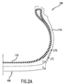
次に、図2Aを参照すると、トレッド領域内において、点Nは、トレッドブロック160の縁部を表し(図3A)、点Gは、トレッドの溝部170の縁部を表す(図3A)。障害物が、点N(即ち、トレッドブロック160の縁部)を滑り落ちる場合、LPNは、障害物が着地またはサイドウォール110と接触するサイドウォール110に沿った径方向位置を表す。障害物が、点G(即ち、トレッドの溝部170の縁部)を滑り落ちる場合、LPGは、障害物が最初にサイドウォール110に接触するサイドウォール110に沿った径方向位置を表す。
2A, in the tread region, point N represents the edge of the tread block 160 (FIG. 3A), and point G represents the edge of the tread groove 170 (FIG. 3A). If the obstacle slides down point N (ie, the edge of the tread block 160), the LPN represents the radial position along the
LPGまたはLPNの径方向位置は、数学的にまたは実験によって決定することができる。例えば、図2B及び2Cは、それぞれ、LPN及びLPGを決定する多くの方法のうちの1つの例示的な図を提供する。まず、図2Bを参照すると、点N及び点Gを通過する直線10を描写する。次に直線20は、線10がカーカス115を通過する場所にあるタイヤカーカス115に接して構成される。次に、直線30は、線20と垂直に線10及び20を横切る点を通り、描写される。長さ40は、点Nから線30までのサイドウォール110に沿った距離を表す。長さ50は、長さ40と等しく、サイドウォール110に沿った線30からLPNの距離を表す。同様に、LPGの位置は、図2Cに示されるように決定され得る。長さ60は点Gから線30までのサイドウォール110に沿った距離を表す。長さ70は、長さ60と等しく、サイドウォール110に沿った線30からLPGの距離を表す。
The radial position of LPG or LPN can be determined mathematically or experimentally. For example, FIGS. 2B and 2C provide exemplary diagrams of one of many methods for determining LPN and LPG, respectively. First, referring to FIG. 2B, a
上述の技術を使用して算出されるように、LPG及びLPNの最終的な位置は、その使用間に予想されるタイヤの特定の構成及び/またはオフロードの状況に基づき、調製される必要があり得る。LPN及びLPGの最終的な位置は、図2B及び2Cに示される技術を使用して算出される位置からサイドウォール110に沿って、約−15mm〜+5mmに設置され得る。前述したように、LPG及びLPNの位置は、同様に他の方法によって決定され得る。例えば、トレッドの溝部170またはトレッドブロック160を滑り落ちた後、障害物が接触する、サイドウォール110に沿った実際の設置場を決定するために実験は行われ得る。
As calculated using the techniques described above, the final location of the LPG and LPN needs to be adjusted based on the specific configuration of the tire and / or off-road conditions expected during its use. possible. The final position of the LPN and LPG may be placed about −15 mm to +5 mm along the
図3Aは、より詳細に示す、サイドウォール110及びトレッド領域105を有するタイヤ100の側面図である。LPN及びLPGの算出を使用して、環140及び150は、サイドウォール110上に重ねられている。環140は、タイヤ100のサイドウォール110に対するLPNの円周位置を表し、一方、環150は、サイドウォール110に対するLPGの円周位置を表す。LPGの環150は、常に、LPNの環140よりもトレッド領域105の近くに設置されるであろう。環130は、タイヤ110の赤道の位置を表す。環120は、リムを受けるタイヤ100の設置場を表す。タイヤ100のトレッド領域105は、示されるように、タイヤ肩部に沿ったトレッドブロック160及びトレッドの溝部170をも含む。部図3Aにしめすようなもの以外の形状及び大きさを有するブロック及び溝部も、同様に本発明で使用し得る。
FIG. 3A is a side view of
上記数式1及び2を使用して、トレッドブロック160及びトレッドの溝部170の縁部を滑り落ちる障害物の軌跡を算出しており、サイドウォール110上に重ねている。より詳細には、図3〜3Cに示すように、軌跡180は、末端175間のトレッドの溝部170を一括し、タイヤ100が回転し、障害物と接触し、その後障害物を越えて、障害物が溝部170のどこかへ動き始めた場合、障害物が動く場所内の領域を定める。同様に、軌跡190は、末端165を用いてトレッドブロック160を一括し、タイヤ100が回転し、障害物と接触し、その後障害物を越えて、障害物がトレッドブロック160のどこかへ動き始めた場合、障害物が動く場所内の領域を定める。図3Bを参照すると、より詳細には、駆動間に障害物がトレッドの溝部170を滑り落ちる場合、障害物は、溝状軌跡180の曲線間を移動するであろう。同様に、図3Cを参照すると、駆動間に、障害物がトレッドブロック160を滑り落ちる場合、障害物は、ブロック状軌跡190の曲線間を移動するであろう。
The trajectories of obstacles sliding down the edges of the
従って、環120、130、及び140に加えて、軌跡180及び190は、タイヤ100の駆動間にサイドウォール110の破裂またはパンクの懸念がある1つまたは複数の接触領域を特定することを補助する。このように、それら接触領域は、サイドウォール100へのトレッド特徴部の追加のような保護の追加を考慮した好ましい設置場を表す。美観的考慮も、それら接触領域の特定を使用して適用され得る。
Thus, in addition to
例えば、図3Bを参照すると、溝状接触領域200(クロスハッチングで表す)は、溝部170を滑り落ちる障害物に対して、サイドウォール110を保護するためにトレッド特徴部を追加する好ましい位置を表示する。接触領域200は、軌跡180、LPN環140及びLPG環150によって接合される。接触領域200に追加されるトレッド特徴部の厚さ(即ち、周囲のサイドウォール110の上部にあるトレッド特徴部の高さ)は、どのくらい性能の改善が望まれるかによって決定される。一般的に、そのようなトレッド特徴部は、厚さが約3mm〜約15mmの範囲であるべきである。厚い特徴部は、材料面での費用の増加、及びタイヤへの重さの付加があるが、より良い保護を提供するであろう。それは、長時間駆動すると、タイヤを損傷させ得る過剰な熱をも発生し得る。薄い特徴部(即ち、3mm未満)を使用することもできるが、さらなる保護を提供するためには、LPN環140を越えて、トレッド特徴部の下部b(線b)を拡張することが望ましい。是非とも、好ましくは、トレッド特徴部の上部(線a)及びトレッド特徴部の下部(線b)の距離は、少なくとも約10mmであるべきであり、環140及び150にそれぞれ正確に設置される必要はない。
For example, referring to FIG. 3B, the grooved contact area 200 (represented by cross-hatching) displays a preferred location to add a tread feature to protect the
同様に、図3Cのブロック状接触領域210(クロスハッチングで表す)は、トレッドブロック160を滑り落ちる障害物に対する保護のためにトレッド特徴部を追加する好ましい位置を示す。領域210は、軌跡190、赤道環130及びLPN環140によって接合される。重ねて、トレッド特徴部の厚さは、好ましくは、所望の保護の量に依存し、約3mm〜約15mmの範囲である。厚さ3mm未満の特徴部は、さらなる保護を提供するよう、赤道環130を越えて、特徴部の下部(線B)を移動することが要求され得る。好ましくは、トレッド特徴部の上部(線A)とトレッド特徴部の下部(線B)間の距離は、径方向に沿って、少なくとも約10mmであるべきである。
Similarly, the block-like contact area 210 (represented by cross-hatching) in FIG.
特定のタイヤ構成のためのトレッドブロックと溝部の相対的な幅によっては、上述のようにタイヤ特徴部の追加が重複につながることがある。例えば、トレッド特徴部が、タイヤ100の各トレッドブロック160の接触領域210と同一の広がりを持って配置される場合、連続的なリブまたはリングがサイドウォール110に形成されるであろう。そのような特徴部はサイドウォール105に十分な保護を提供し得るが、固体のリングは、美観または泥を牽引する点から十分ではない場合がある。それは、長時間駆動すると、タイヤが損傷し得る過剰な熱をも発生し得る。従って、上述のように、美観、泥の牽引及び熱の発生のような他の懸念をも対処する一方、サイドウォールの保護を最適化するために、接触領域を特定することにより提供される情報を使用して、トレッド特徴部は、互い違いに、あるいは、サイドウォールに沿って形作られ、操作され得る。加えて、トレッド特徴部は、予想される接触領域の設置を知ることに基づき、サイドウォールの保護を提供する一方、接触領域と同一の広がりに、または接触領域から中心を外した場所に配置され得る。
Depending on the relative width of the tread block and groove for a particular tire configuration, the addition of tire features may lead to duplication as described above. For example, if the tread feature is disposed with the same extent as the
図4は、トレッドブロック460及びトレッドの溝部470を有するタイヤ400の一部を表す。溝部470の縁部に基づく軌跡480及びブロック460の縁部に基づく軌跡490をも示す。上述の方法を使用して。溝状トレッド特徴部50は、溝部を滑り落ちる障害物からサイドウォール410を保護するために溝部470の下に放射状に配置されている。同様に、ブロック状トレッド特徴部510は、ブロックを滑り落ちる障害物からサイドウォール410を保護するためにブロック460の下に放射状に配置されている。美観を改善するため、特徴部500及び特徴部510は、図4に示すように形作られ、交互に配置されている。他の形状や向きを適用してもよい。しかし、そのような特徴部の配置は、本明細書に記載される方法を使用して想到される。
FIG. 4 illustrates a portion of a
本発明の特定の主題が、その特定の例示的な実施形態及び方法に関して、詳細に記載されている一方、当業者が、前述の理解を得て、そのような実施形態の代替物、変形特徴及び等価物を容易に製造し得ることを理解されたい。従って、本開示の範囲は、限定というよりもむしろ一例とされており、本主題の開示は、当業者にとって容易に明らかとなるような本主題の修正、変形、及び/または追加を含むことを防げることはない。 While specific subject matter of the invention has been described in detail with respect to specific exemplary embodiments and methods thereof, those of ordinary skill in the art, with the foregoing understanding, will find alternatives, variations and features of such embodiments. And it should be understood that equivalents can be readily manufactured. Accordingly, the scope of the present disclosure is intended to be exemplary rather than limiting, and the disclosure of the present subject matter includes modifications, variations, and / or additions of the present subject matter that will be readily apparent to those skilled in the art. There is no prevention.
Claims (15)
前記タイヤは、タイヤの周方向に垂直な平面に沿った切断面から見てタイヤが最も幅広である部分のサイドウォールに沿った径方向の場所である赤道を有し、
前記タイヤは、前記タイヤの肩部に沿って配置されるトレッドブロック及びトレッドの溝部を有し、
前記タイヤは、
前記タイヤの前記サイドウォールに沿って設置される複数のブロック状トレッド特徴部と、
前記タイヤの前記サイドウォールに沿って設置される複数の溝状トレッド特徴部と、を備え、
前記ブロック状トレッド特徴部は、前記トレッドブロックの半径方向下方、かつ、前記タイヤの前記サイドウォールに沿って配置され、かつ、前記赤道、LPN、及び前記タイヤが前記障害物を越えて回転し、前記障害物が前記トレッドブロックを滑り落ちる場合、前記障害物が前記タイヤの前記サイドウォールに沿って移動する第1領域により境界付けられ、
前記溝状トレッド特徴部は、前記トレッドの溝部の半径方向下方、かつ、前記タイヤの前記サイドウォールに沿って配置され、かつ、LPN、LPG、及び前記タイヤが前記障害物を越えて回転し、前記障害物が前記トレッドの溝部を滑り落ちる場合、前記障害物が前記タイヤの前記サイドウォールに沿って移動する第2領域により境界付けられ、
前記LPGは障害物との接触を受けた後でタイヤがその経路に沿って回転する時、障害物がトレッドの溝の縁部から滑り落ちる場合、障害物がタイヤのサイドウォールに最初に接触する径方向位置であるタイヤ。 A tire with improved protection against obstacles that damage the sidewalls,
The tire has an equator which is a radial place along a sidewall of a portion where the tire is widest when viewed from a cut surface along a plane perpendicular to the circumferential direction of the tire ,
The tire has a tread block and a tread groove disposed along a shoulder of the tire,
The tire is
A plurality of block-shaped tread features installed along the sidewall of the tire;
A plurality of grooved tread features installed along the sidewalls of the tire,
It said block-like tread feature is radially below the tread blocks and are arranged along the sidewall of the tire, and the equatorial, LPN, and the tire is rotated beyond the obstacle, When the obstacle slides down the tread block, the obstacle is bounded by a first region that moves along the sidewall of the tire ;
Said groove-like tread feature is radially below the groove of the tread and, disposed along said sidewall of said tire and rotated beyond LPN, LPG, and the tire is the obstacle, When the obstacle slides down the groove portion of the tread, the obstacle is bounded by a second region that moves along the sidewall of the tire;
The LPG is the diameter at which the obstacle first contacts the tire sidewall if the obstacle slides off the edge of the tread groove when the tire rotates along its path after contact with the obstacle. A tire that is a directional position.
R=タイヤの半径
θ=タイヤの回転量
Lo=タイヤ中心Oに対する障害物P0の最初の水平位置
Ho=タイヤ中心Oに対する障害物P0の最初の垂直位置
r=障害物の径方向座標
α=障害物の角度座標)
を使用して決定される請求項1に記載のサイドウォールを損傷する障害物に対する保護を改善したタイヤ。 The first and second regions have the following formulas
R = radial coordinate of the radius theta = rotation amount Lo = initial vertical position r = an obstacle of the obstacle P 0 for the first horizontal position Ho = tire center O of the obstacle P 0 with respect to the tire center O of the tire of the tire α = Angle coordinates of obstacles)
A tire with improved protection against obstacles that damage the sidewalls of claim 1 determined using
Applications Claiming Priority (1)
| Application Number | Priority Date | Filing Date | Title |
|---|---|---|---|
| PCT/US2010/039567 WO2011162748A1 (en) | 2010-06-23 | 2010-06-23 | Tire with improved resistance to sidewall damage |
Publications (2)
| Publication Number | Publication Date |
|---|---|
| JP2013529573A JP2013529573A (en) | 2013-07-22 |
| JP5717850B2 true JP5717850B2 (en) | 2015-05-13 |
Family
ID=45371706
Family Applications (1)
| Application Number | Title | Priority Date | Filing Date |
|---|---|---|---|
| JP2013516551A Expired - Fee Related JP5717850B2 (en) | 2010-06-23 | 2010-06-23 | Tires with improved sidewall damage resistance |
Country Status (7)
| Country | Link |
|---|---|
| US (1) | US9168793B2 (en) |
| EP (1) | EP2585318B1 (en) |
| JP (1) | JP5717850B2 (en) |
| CN (1) | CN102947107B (en) |
| BR (1) | BR112012033083B1 (en) |
| MX (1) | MX2013000090A (en) |
| WO (1) | WO2011162748A1 (en) |
Families Citing this family (10)
| Publication number | Priority date | Publication date | Assignee | Title |
|---|---|---|---|---|
| JP6139843B2 (en) | 2012-10-05 | 2017-05-31 | 株式会社ブリヂストン | Pneumatic tire |
| FR3007691B1 (en) * | 2013-06-28 | 2016-11-04 | Michelin & Cie | TIRE WITH RADIAL OR CROSS CARCASS |
| DE102014218662A1 (en) * | 2014-09-17 | 2016-03-31 | Continental Reifen Deutschland Gmbh | Vehicle tires |
| CN108473003A (en) * | 2015-12-25 | 2018-08-31 | 米其林企业总公司 | With radial or biasing carcass tire |
| FR3056939A1 (en) | 2016-10-04 | 2018-04-06 | Compagnie Generale Des Etablissements Michelin | DEVICE FOR PROTECTING A TIRE FLANK |
| JP6774306B2 (en) * | 2016-11-09 | 2020-10-21 | Toyo Tire株式会社 | Pneumatic tires |
| JP6774307B2 (en) * | 2016-11-09 | 2020-10-21 | Toyo Tire株式会社 | Pneumatic tires |
| TWI631025B (en) * | 2017-03-06 | 2018-08-01 | 特耐橡膠工業有限公司 | Strengthening structure for sidewall of tire |
| FR3066436B1 (en) | 2017-05-16 | 2020-07-10 | Compagnie Generale Des Etablissements Michelin | DEVICE FOR PROTECTING A TIRE SIDE |
| JP6929210B2 (en) * | 2017-12-11 | 2021-09-01 | 株式会社ブリヂストン | tire |
Family Cites Families (20)
| Publication number | Priority date | Publication date | Assignee | Title |
|---|---|---|---|---|
| JPS5225301A (en) | 1975-08-14 | 1977-02-25 | Toyo Tire & Rubber Co Ltd | Penumatic tire |
| DE2549668A1 (en) | 1975-11-05 | 1977-05-12 | Uniroyal Ag | VEHICLE TIRES WITH RADIAL CARCASS |
| US4144921A (en) * | 1976-03-03 | 1979-03-20 | Nissan Motor Company, Limited | Pneumatic tire with an internal damage indicator |
| JPS5539802A (en) | 1978-08-24 | 1980-03-21 | Bridgestone Corp | Skid-resisting air tire for high load and high speed |
| JPS6122001Y2 (en) * | 1981-04-30 | 1986-07-02 | ||
| US4982773A (en) | 1989-04-03 | 1991-01-08 | The Goodyear Tire & Rubber Company | Pneumatic tire including spaced sidewall projections |
| JPH04129805A (en) | 1990-09-21 | 1992-04-30 | Sumitomo Rubber Ind Ltd | Pneumatic tire |
| JP2977601B2 (en) | 1990-11-13 | 1999-11-15 | 株式会社ブリヂストン | Pneumatic tire |
| JP3125109B2 (en) * | 1991-12-27 | 2001-01-15 | 横浜ゴム株式会社 | Pneumatic radial tires for passenger cars |
| JPH06183210A (en) * | 1992-12-17 | 1994-07-05 | Ohtsu Tire & Rubber Co Ltd :The | Pneumatic tire |
| JPH0986107A (en) | 1995-09-22 | 1997-03-31 | Bridgestone Corp | Pneumatic radial tire for urban area travelling bus |
| US6000451A (en) | 1996-07-19 | 1999-12-14 | Sumitomo Rubber Industries, Ltd. | Pneumatic tire including at least one projection |
| US6189586B1 (en) | 1998-10-15 | 2001-02-20 | Warren L. Guidry | Pneumatic rubber tire for on/off-road vehicles |
| JP2002205514A (en) * | 2001-01-05 | 2002-07-23 | Yokohama Rubber Co Ltd:The | Pneumatic tire for heavy load |
| US6920906B2 (en) | 2001-08-31 | 2005-07-26 | Bridgestone/Firestone North American Tire, Llc | Pneumatic tire with sidewall projections |
| JP4202169B2 (en) * | 2003-03-28 | 2008-12-24 | 東洋ゴム工業株式会社 | Pneumatic radial tire |
| US7784511B2 (en) | 2007-03-02 | 2010-08-31 | The Goodyear Tire & Rubber Company | Pneumatic tire having extension blocks |
| US8434534B2 (en) | 2007-08-24 | 2013-05-07 | Michelin Recherche Et Technique | Tire having sidewall protection |
| JP4980872B2 (en) * | 2007-12-20 | 2012-07-18 | 東洋ゴム工業株式会社 | Pneumatic tire |
| DE102008007548A1 (en) * | 2008-02-05 | 2009-08-06 | Continental Aktiengesellschaft | Vehicle tires |
-
2010
- 2010-06-23 BR BR112012033083-7A patent/BR112012033083B1/en active IP Right Grant
- 2010-06-23 MX MX2013000090A patent/MX2013000090A/en not_active Application Discontinuation
- 2010-06-23 WO PCT/US2010/039567 patent/WO2011162748A1/en active Application Filing
- 2010-06-23 CN CN201080067613.7A patent/CN102947107B/en active Active
- 2010-06-23 JP JP2013516551A patent/JP5717850B2/en not_active Expired - Fee Related
- 2010-06-23 US US13/806,540 patent/US9168793B2/en active Active
- 2010-06-23 EP EP10853791.1A patent/EP2585318B1/en active Active
Also Published As
| Publication number | Publication date |
|---|---|
| BR112012033083B1 (en) | 2020-12-08 |
| EP2585318A1 (en) | 2013-05-01 |
| WO2011162748A1 (en) | 2011-12-29 |
| BR112012033083A2 (en) | 2016-11-22 |
| EP2585318B1 (en) | 2016-12-28 |
| MX2013000090A (en) | 2013-02-27 |
| EP2585318A4 (en) | 2014-05-14 |
| US20130092308A1 (en) | 2013-04-18 |
| US9168793B2 (en) | 2015-10-27 |
| CN102947107A (en) | 2013-02-27 |
| CN102947107B (en) | 2016-08-03 |
| BR112012033083A8 (en) | 2018-01-02 |
| JP2013529573A (en) | 2013-07-22 |
Similar Documents
| Publication | Publication Date | Title |
|---|---|---|
| JP5717850B2 (en) | Tires with improved sidewall damage resistance | |
| KR101974461B1 (en) | Pneumatic tire | |
| KR101909981B1 (en) | Pneumatic tire | |
| EP2150421B1 (en) | Rim protector | |
| US10787042B2 (en) | Device for protecting a tire wall | |
| JP5717851B2 (en) | How to improve the damage resistance of tire sidewalls | |
| US20130118664A1 (en) | Heavy duty tire | |
| WO2016121763A1 (en) | Pneumatic tire | |
| KR101695301B1 (en) | Sidewall protector ribs | |
| CN109466255B (en) | Pneumatic tire | |
| AU2012321677A1 (en) | Pneumatic tire | |
| JP2017507842A (en) | Civil engineering type vehicle tires with improved durability | |
| JP6148719B2 (en) | Tire tread with grooves with internal space | |
| JP6107242B2 (en) | Pneumatic tire | |
| US20200114700A1 (en) | Stud Pin and Studded Tire | |
| JP6399123B2 (en) | Pneumatic tire | |
| EP3590735B1 (en) | Stud pin and studded tire | |
| JPH0717213A (en) | Pneumatic radial tier for heavy load | |
| JP2019093907A (en) | Pneumatic tire | |
| JPH09300920A (en) | Wasteland travelling pneumatic tire | |
| EP3590737B1 (en) | Stud pin and studded tire | |
| EP3590734B1 (en) | Stud pin and studded tire | |
| JP6365719B1 (en) | Pneumatic tire | |
| JP6822186B2 (en) | Pneumatic tires |
Legal Events
| Date | Code | Title | Description |
|---|---|---|---|
| A977 | Report on retrieval |
Free format text: JAPANESE INTERMEDIATE CODE: A971007 Effective date: 20131224 |
|
| A131 | Notification of reasons for refusal |
Free format text: JAPANESE INTERMEDIATE CODE: A131 Effective date: 20131226 |
|
| A521 | Request for written amendment filed |
Free format text: JAPANESE INTERMEDIATE CODE: A523 Effective date: 20140320 |
|
| A131 | Notification of reasons for refusal |
Free format text: JAPANESE INTERMEDIATE CODE: A131 Effective date: 20140825 |
|
| A521 | Request for written amendment filed |
Free format text: JAPANESE INTERMEDIATE CODE: A523 Effective date: 20141110 |
|
| TRDD | Decision of grant or rejection written | ||
| A01 | Written decision to grant a patent or to grant a registration (utility model) |
Free format text: JAPANESE INTERMEDIATE CODE: A01 Effective date: 20150302 |
|
| A61 | First payment of annual fees (during grant procedure) |
Free format text: JAPANESE INTERMEDIATE CODE: A61 Effective date: 20150317 |
|
| R150 | Certificate of patent or registration of utility model |
Ref document number: 5717850 Country of ref document: JP Free format text: JAPANESE INTERMEDIATE CODE: R150 |
|
| R250 | Receipt of annual fees |
Free format text: JAPANESE INTERMEDIATE CODE: R250 |
|
| LAPS | Cancellation because of no payment of annual fees |