JP5713708B2 - Contact-operated lancet device - Google Patents
Contact-operated lancet device Download PDFInfo
- Publication number
- JP5713708B2 JP5713708B2 JP2011018990A JP2011018990A JP5713708B2 JP 5713708 B2 JP5713708 B2 JP 5713708B2 JP 2011018990 A JP2011018990 A JP 2011018990A JP 2011018990 A JP2011018990 A JP 2011018990A JP 5713708 B2 JP5713708 B2 JP 5713708B2
- Authority
- JP
- Japan
- Prior art keywords
- lancet
- housing
- shield
- lever
- lancet device
- Prior art date
- Legal status (The legal status is an assumption and is not a legal conclusion. Google has not performed a legal analysis and makes no representation as to the accuracy of the status listed.)
- Active
Links
- 230000033001 locomotion Effects 0.000 claims abstract description 56
- 230000000717 retained effect Effects 0.000 claims abstract description 7
- 230000006835 compression Effects 0.000 claims description 21
- 238000007906 compression Methods 0.000 claims description 21
- 230000014759 maintenance of location Effects 0.000 claims description 12
- 210000003811 finger Anatomy 0.000 description 27
- 239000008280 blood Substances 0.000 description 17
- 210000004369 blood Anatomy 0.000 description 17
- 230000001681 protective effect Effects 0.000 description 9
- 238000000034 method Methods 0.000 description 8
- 230000002093 peripheral effect Effects 0.000 description 8
- 244000208734 Pisonia aculeata Species 0.000 description 5
- 230000004913 activation Effects 0.000 description 5
- 230000009471 action Effects 0.000 description 4
- 239000004033 plastic Substances 0.000 description 4
- 239000000853 adhesive Substances 0.000 description 3
- 230000001070 adhesive effect Effects 0.000 description 3
- 230000036512 infertility Effects 0.000 description 3
- 239000000463 material Substances 0.000 description 3
- 230000013011 mating Effects 0.000 description 3
- 230000036961 partial effect Effects 0.000 description 3
- 238000012360 testing method Methods 0.000 description 3
- 238000003149 assay kit Methods 0.000 description 2
- HVYWMOMLDIMFJA-DPAQBDIFSA-N cholesterol Chemical compound C1C=C2C[C@@H](O)CC[C@]2(C)[C@@H]2[C@@H]1[C@@H]1CC[C@H]([C@H](C)CCCC(C)C)[C@@]1(C)CC2 HVYWMOMLDIMFJA-DPAQBDIFSA-N 0.000 description 2
- 238000000605 extraction Methods 0.000 description 2
- 230000007246 mechanism Effects 0.000 description 2
- 238000012986 modification Methods 0.000 description 2
- 230000004048 modification Effects 0.000 description 2
- 230000002829 reductive effect Effects 0.000 description 2
- 208000035049 Blood-Borne Infections Diseases 0.000 description 1
- WQZGKKKJIJFFOK-GASJEMHNSA-N Glucose Natural products OC[C@H]1OC(O)[C@H](O)[C@@H](O)[C@@H]1O WQZGKKKJIJFFOK-GASJEMHNSA-N 0.000 description 1
- 238000004458 analytical method Methods 0.000 description 1
- 238000005452 bending Methods 0.000 description 1
- 230000017531 blood circulation Effects 0.000 description 1
- 235000012000 cholesterol Nutrition 0.000 description 1
- 238000007796 conventional method Methods 0.000 description 1
- 238000013461 design Methods 0.000 description 1
- 206010012601 diabetes mellitus Diseases 0.000 description 1
- 201000010099 disease Diseases 0.000 description 1
- 208000037265 diseases, disorders, signs and symptoms Diseases 0.000 description 1
- 230000000694 effects Effects 0.000 description 1
- 239000008103 glucose Substances 0.000 description 1
- 238000002347 injection Methods 0.000 description 1
- 239000007924 injection Substances 0.000 description 1
- 238000001746 injection moulding Methods 0.000 description 1
- 238000003780 insertion Methods 0.000 description 1
- 230000037431 insertion Effects 0.000 description 1
- 230000003993 interaction Effects 0.000 description 1
- 230000000670 limiting effect Effects 0.000 description 1
- 238000012423 maintenance Methods 0.000 description 1
- 230000005541 medical transmission Effects 0.000 description 1
- 239000002906 medical waste Substances 0.000 description 1
- 239000002184 metal Substances 0.000 description 1
- 239000002991 molded plastic Substances 0.000 description 1
- 238000000465 moulding Methods 0.000 description 1
- 238000004806 packaging method and process Methods 0.000 description 1
- 230000000149 penetrating effect Effects 0.000 description 1
- 238000005381 potential energy Methods 0.000 description 1
- 230000002028 premature Effects 0.000 description 1
- 230000002040 relaxant effect Effects 0.000 description 1
- 230000000284 resting effect Effects 0.000 description 1
- 238000005070 sampling Methods 0.000 description 1
- 239000007787 solid Substances 0.000 description 1
- 229910001220 stainless steel Inorganic materials 0.000 description 1
- 239000010935 stainless steel Substances 0.000 description 1
- 210000003813 thumb Anatomy 0.000 description 1
- 230000001960 triggered effect Effects 0.000 description 1
- 230000000007 visual effect Effects 0.000 description 1
Images


Classifications
-
- A—HUMAN NECESSITIES
- A61—MEDICAL OR VETERINARY SCIENCE; HYGIENE
- A61B—DIAGNOSIS; SURGERY; IDENTIFICATION
- A61B5/00—Measuring for diagnostic purposes; Identification of persons
- A61B5/14—Devices for taking samples of blood ; Measuring characteristics of blood in vivo, e.g. gas concentration within the blood, pH-value of blood
- A61B5/1405—Devices for taking blood samples
-
- A—HUMAN NECESSITIES
- A61—MEDICAL OR VETERINARY SCIENCE; HYGIENE
- A61B—DIAGNOSIS; SURGERY; IDENTIFICATION
- A61B17/00—Surgical instruments, devices or methods, e.g. tourniquets
- A61B17/32—Surgical cutting instruments
-
- A—HUMAN NECESSITIES
- A61—MEDICAL OR VETERINARY SCIENCE; HYGIENE
- A61B—DIAGNOSIS; SURGERY; IDENTIFICATION
- A61B5/00—Measuring for diagnostic purposes; Identification of persons
- A61B5/15—Devices for taking samples of blood
- A61B5/150007—Details
- A61B5/150015—Source of blood
- A61B5/150022—Source of blood for capillary blood or interstitial fluid
-
- A—HUMAN NECESSITIES
- A61—MEDICAL OR VETERINARY SCIENCE; HYGIENE
- A61B—DIAGNOSIS; SURGERY; IDENTIFICATION
- A61B5/00—Measuring for diagnostic purposes; Identification of persons
- A61B5/15—Devices for taking samples of blood
- A61B5/150007—Details
- A61B5/150206—Construction or design features not otherwise provided for; manufacturing or production; packages; sterilisation of piercing element, piercing device or sampling device
- A61B5/150259—Improved gripping, e.g. with high friction pattern or projections on the housing surface or an ergonometric shape
-
- A—HUMAN NECESSITIES
- A61—MEDICAL OR VETERINARY SCIENCE; HYGIENE
- A61B—DIAGNOSIS; SURGERY; IDENTIFICATION
- A61B5/00—Measuring for diagnostic purposes; Identification of persons
- A61B5/15—Devices for taking samples of blood
- A61B5/150007—Details
- A61B5/150374—Details of piercing elements or protective means for preventing accidental injuries by such piercing elements
- A61B5/150381—Design of piercing elements
- A61B5/150412—Pointed piercing elements, e.g. needles, lancets for piercing the skin
-
- A—HUMAN NECESSITIES
- A61—MEDICAL OR VETERINARY SCIENCE; HYGIENE
- A61B—DIAGNOSIS; SURGERY; IDENTIFICATION
- A61B5/00—Measuring for diagnostic purposes; Identification of persons
- A61B5/15—Devices for taking samples of blood
- A61B5/150007—Details
- A61B5/150374—Details of piercing elements or protective means for preventing accidental injuries by such piercing elements
- A61B5/150381—Design of piercing elements
- A61B5/150503—Single-ended needles
- A61B5/150511—Details of construction of shaft
-
- A—HUMAN NECESSITIES
- A61—MEDICAL OR VETERINARY SCIENCE; HYGIENE
- A61B—DIAGNOSIS; SURGERY; IDENTIFICATION
- A61B5/00—Measuring for diagnostic purposes; Identification of persons
- A61B5/15—Devices for taking samples of blood
- A61B5/150007—Details
- A61B5/150374—Details of piercing elements or protective means for preventing accidental injuries by such piercing elements
- A61B5/150381—Design of piercing elements
- A61B5/150503—Single-ended needles
- A61B5/150519—Details of construction of hub, i.e. element used to attach the single-ended needle to a piercing device or sampling device
-
- A—HUMAN NECESSITIES
- A61—MEDICAL OR VETERINARY SCIENCE; HYGIENE
- A61B—DIAGNOSIS; SURGERY; IDENTIFICATION
- A61B5/00—Measuring for diagnostic purposes; Identification of persons
- A61B5/15—Devices for taking samples of blood
- A61B5/150007—Details
- A61B5/150374—Details of piercing elements or protective means for preventing accidental injuries by such piercing elements
- A61B5/150534—Design of protective means for piercing elements for preventing accidental needle sticks, e.g. shields, caps, protectors, axially extensible sleeves, pivotable protective sleeves
- A61B5/150541—Breakable protectors, e.g. caps, shields or sleeves, i.e. protectors separated destructively, e.g. by breaking a connecting area
- A61B5/150549—Protectors removed by rotational movement, e.g. torsion or screwing
-
- A—HUMAN NECESSITIES
- A61—MEDICAL OR VETERINARY SCIENCE; HYGIENE
- A61B—DIAGNOSIS; SURGERY; IDENTIFICATION
- A61B5/00—Measuring for diagnostic purposes; Identification of persons
- A61B5/15—Devices for taking samples of blood
- A61B5/150007—Details
- A61B5/150374—Details of piercing elements or protective means for preventing accidental injuries by such piercing elements
- A61B5/150534—Design of protective means for piercing elements for preventing accidental needle sticks, e.g. shields, caps, protectors, axially extensible sleeves, pivotable protective sleeves
- A61B5/150541—Breakable protectors, e.g. caps, shields or sleeves, i.e. protectors separated destructively, e.g. by breaking a connecting area
- A61B5/150564—Protectors removed by pulling or pushing
-
- A—HUMAN NECESSITIES
- A61—MEDICAL OR VETERINARY SCIENCE; HYGIENE
- A61B—DIAGNOSIS; SURGERY; IDENTIFICATION
- A61B5/00—Measuring for diagnostic purposes; Identification of persons
- A61B5/15—Devices for taking samples of blood
- A61B5/150007—Details
- A61B5/150374—Details of piercing elements or protective means for preventing accidental injuries by such piercing elements
- A61B5/150534—Design of protective means for piercing elements for preventing accidental needle sticks, e.g. shields, caps, protectors, axially extensible sleeves, pivotable protective sleeves
- A61B5/15058—Joining techniques used for protective means
- A61B5/150618—Integrally moulded protectors, e.g. protectors simultaneously moulded together with a further component, e.g. a hub, of the piercing element
-
- A—HUMAN NECESSITIES
- A61—MEDICAL OR VETERINARY SCIENCE; HYGIENE
- A61B—DIAGNOSIS; SURGERY; IDENTIFICATION
- A61B5/00—Measuring for diagnostic purposes; Identification of persons
- A61B5/15—Devices for taking samples of blood
- A61B5/150007—Details
- A61B5/150374—Details of piercing elements or protective means for preventing accidental injuries by such piercing elements
- A61B5/150534—Design of protective means for piercing elements for preventing accidental needle sticks, e.g. shields, caps, protectors, axially extensible sleeves, pivotable protective sleeves
- A61B5/150694—Procedure for removing protection means at the time of piercing
- A61B5/150717—Procedure for removing protection means at the time of piercing manually removed
-
- A—HUMAN NECESSITIES
- A61—MEDICAL OR VETERINARY SCIENCE; HYGIENE
- A61B—DIAGNOSIS; SURGERY; IDENTIFICATION
- A61B5/00—Measuring for diagnostic purposes; Identification of persons
- A61B5/15—Devices for taking samples of blood
- A61B5/150007—Details
- A61B5/150801—Means for facilitating use, e.g. by people with impaired vision; means for indicating when used correctly or incorrectly; means for alarming
- A61B5/150824—Means for facilitating use, e.g. by people with impaired vision; means for indicating when used correctly or incorrectly; means for alarming by visual feedback
-
- A—HUMAN NECESSITIES
- A61—MEDICAL OR VETERINARY SCIENCE; HYGIENE
- A61B—DIAGNOSIS; SURGERY; IDENTIFICATION
- A61B5/00—Measuring for diagnostic purposes; Identification of persons
- A61B5/15—Devices for taking samples of blood
- A61B5/150007—Details
- A61B5/150885—Preventing re-use
- A61B5/150916—Preventing re-use by blocking components, e.g. piston, driving device or fluid passageway
-
- A—HUMAN NECESSITIES
- A61—MEDICAL OR VETERINARY SCIENCE; HYGIENE
- A61B—DIAGNOSIS; SURGERY; IDENTIFICATION
- A61B5/00—Measuring for diagnostic purposes; Identification of persons
- A61B5/15—Devices for taking samples of blood
- A61B5/151—Devices specially adapted for taking samples of capillary blood, e.g. by lancets, needles or blades
- A61B5/15101—Details
- A61B5/15103—Piercing procedure
- A61B5/15107—Piercing being assisted by a triggering mechanism
- A61B5/15111—Semi-automatically triggered, e.g. at the end of the cocking procedure, for instance by biasing the main drive spring or when reaching sufficient contact pressure, the piercing device is automatically triggered without any deliberate action by the user
-
- A—HUMAN NECESSITIES
- A61—MEDICAL OR VETERINARY SCIENCE; HYGIENE
- A61B—DIAGNOSIS; SURGERY; IDENTIFICATION
- A61B5/00—Measuring for diagnostic purposes; Identification of persons
- A61B5/15—Devices for taking samples of blood
- A61B5/151—Devices specially adapted for taking samples of capillary blood, e.g. by lancets, needles or blades
- A61B5/15101—Details
- A61B5/15103—Piercing procedure
- A61B5/15107—Piercing being assisted by a triggering mechanism
- A61B5/15113—Manually triggered, i.e. the triggering requires a deliberate action by the user such as pressing a drive button
-
- A—HUMAN NECESSITIES
- A61—MEDICAL OR VETERINARY SCIENCE; HYGIENE
- A61B—DIAGNOSIS; SURGERY; IDENTIFICATION
- A61B5/00—Measuring for diagnostic purposes; Identification of persons
- A61B5/15—Devices for taking samples of blood
- A61B5/151—Devices specially adapted for taking samples of capillary blood, e.g. by lancets, needles or blades
- A61B5/15101—Details
- A61B5/15115—Driving means for propelling the piercing element to pierce the skin, e.g. comprising mechanisms based on shape memory alloys, magnetism, solenoids, piezoelectric effect, biased elements, resilient elements, vacuum or compressed fluids
- A61B5/15117—Driving means for propelling the piercing element to pierce the skin, e.g. comprising mechanisms based on shape memory alloys, magnetism, solenoids, piezoelectric effect, biased elements, resilient elements, vacuum or compressed fluids comprising biased elements, resilient elements or a spring, e.g. a helical spring, leaf spring, or elastic strap
-
- A—HUMAN NECESSITIES
- A61—MEDICAL OR VETERINARY SCIENCE; HYGIENE
- A61B—DIAGNOSIS; SURGERY; IDENTIFICATION
- A61B5/00—Measuring for diagnostic purposes; Identification of persons
- A61B5/15—Devices for taking samples of blood
- A61B5/151—Devices specially adapted for taking samples of capillary blood, e.g. by lancets, needles or blades
- A61B5/15101—Details
- A61B5/15126—Means for controlling the lancing movement, e.g. 2D- or 3D-shaped elements, tooth-shaped elements or sliding guides
- A61B5/1513—Means for controlling the lancing movement, e.g. 2D- or 3D-shaped elements, tooth-shaped elements or sliding guides comprising linear sliding guides
-
- A—HUMAN NECESSITIES
- A61—MEDICAL OR VETERINARY SCIENCE; HYGIENE
- A61B—DIAGNOSIS; SURGERY; IDENTIFICATION
- A61B5/00—Measuring for diagnostic purposes; Identification of persons
- A61B5/15—Devices for taking samples of blood
- A61B5/151—Devices specially adapted for taking samples of capillary blood, e.g. by lancets, needles or blades
- A61B5/15142—Devices intended for single use, i.e. disposable
- A61B5/15144—Devices intended for single use, i.e. disposable comprising driving means, e.g. a spring, for retracting the piercing unit into the housing
Abstract
Description
(関連出願の相互参照)
本出願は、2004年5月7日に出願された米国特許出願第60/569,424号、2004年11月30日に出願された米国特許出願第60/631,846号、2004年11月30日に出願された米国特許出願第60/631,795号、および2005年4月7日に出願された米国特許出願第60/669,276号の優先権を主張するものである。
(Cross-reference of related applications)
This application is filed on U.S. Patent Application No. 60 / 569,424 filed May 7, 2004, U.S. Patent Application No. 60 / 631,846 filed Nov. 30, 2004, Nov. 2004. US
本発明は、一般に、患者から血液サンプルを採取するために用いられる、一般にランセットと呼ばれる医療用穿刺装置に関し、より具体的には、通常の使用時に装置に接触する際に達成される作動の操作性が向上するように設計されたランセット装置に関する。 The present invention relates generally to a medical puncture device, commonly referred to as a lancet, that is used to obtain a blood sample from a patient, and more particularly to the operation of operation achieved upon contact with the device during normal use. The present invention relates to a lancet device designed to improve performance.
ランセット装置は、患者の皮膚を穿刺し、患者から毛細血管の血液サンプルを得るために、医療分野において用いられるものである。糖尿病のような特定の病気では、例えば、患者の血糖レベルを監視するために、患者の血液を規則的に試験することが必要である。さらに、コレステロール試験キットのような試験キットは、分析用の血液サンプルを必要とすることが多い。血液採取手順は、通常、血液サンプルを得るために、指または他の適切な身体部分を刺すことを含む。一般的に、このような試験に必要とされる血液量は比較的少量であり、通常、これらの試験に十分な量の血液は、小さな刺し傷または切開によって与えられる。 The lancet device is used in the medical field in order to puncture a patient's skin and obtain a capillary blood sample from the patient. In certain diseases, such as diabetes, it is necessary to test the patient's blood regularly, for example, to monitor the patient's blood glucose level. In addition, test kits such as cholesterol test kits often require a blood sample for analysis. A blood collection procedure typically involves pricking a finger or other suitable body part to obtain a blood sample. In general, the amount of blood required for such tests is relatively small, and a sufficient amount of blood for these tests is usually provided by small punctures or incisions.
種々のランセット装置が、病院、診療所、医院等および個々の消費者にとって商業的に利用可能である。一般に、こうした装置は、患者の皮膚に迅速に刺し傷を付けるかまたは切開を行い、少量の血液流出をもたらすために用いられる、針のような先の尖った部材またはブレードのような鋭い部材を含む。多くの人々にとって、手持ち式の針またはブレードで自分の指を刺すことは、生理的かつ心理的に困難であることが多い。その結果、ランセット装置は、トリガ機構の作動時に患者の皮膚を穿刺するまたは切る自動装置に発展した。幾つかの装置においては、患者からの血液の抜き取りを担当する医療専門家または患者自身であるユーザによってトリガされるまで、針またはブレードは待機位置に保持される。トリガすると、針またはブレードは、例えば、指の皮膚のような患者の皮膚を穿刺するかまたは切る。多くの場合、患者の皮膚を穿刺するまたは切るのに必要な「機械的な」力を与えるために、装置内にばねが組み込まれる。 Various lancet devices are commercially available for hospitals, clinics, clinics, etc. and individual consumers. In general, such devices use sharp or sharp members such as needles or blades that are used to quickly puncture or incise the patient's skin and produce a small amount of blood outflow. Including. For many people, it is often difficult to stab their fingers with a hand-held needle or blade, both physiologically and psychologically. As a result, lancet devices have evolved into automatic devices that puncture or cut the patient's skin when the trigger mechanism is activated. In some devices, the needle or blade is held in a standby position until triggered by a user who is the medical professional responsible for drawing blood from the patient or the patient himself. Upon triggering, the needle or blade punctures or cuts the patient's skin, for example, finger skin. In many cases, a spring is incorporated into the device to provide the “mechanical” force necessary to puncture or cut the patient's skin.
使用前に、こうした医療用穿刺装置またはランセットが滅菌状態にあることは、医療分野において最も重要である。今日、ほぼ例外なく、医療用穿刺装置またはランセットは、医療専門家およびこのような装置に対する必要性を有する一般の人に分配される前に、滅菌状態で製造され、包装される。滅菌包装は、装置の滅菌状態を維持し、使用するまで周囲環境が装置を汚染しないことを保証する。さらに、ユーザまたは別の人が、装置の使用後に針またはブレードに接触しないことも、より一層重要である。血液感染性の病気に対する懸念から、医療専門家が患者の血液と接触する医療装置に大きな関心を払うことが必要とされる。したがって、ランセットの設計の重要な側面は、血液サンプルが患者から抜き取られた後、装置の針またはブレードが、ユーザまたは別の人を傷つけるのを防止することを含む。一旦使用されると、針またはブレードが装置を取り扱うユーザまたは別の人を傷つけるのを防止するように、針またはブレードは遮蔽されるべきである。さらに、針またはブレードが一人より多い人に用いられることによる疾病伝播の機会を排除するように、ランセット装置は使い捨て可能であるべきである。この点で、ランセット装置は、理想的には、1回の発射用に設計され、再使用を防ぐための安全な形状構成を有するべきである。 It is most important in the medical field that these medical puncture devices or lancets are in a sterile state before use. Today, with almost no exception, medical puncture devices or lancets are manufactured and packaged in a sterile state before being distributed to medical professionals and the general population having a need for such devices. Sterile packaging maintains the sterility of the device and ensures that the surrounding environment does not contaminate the device until use. It is even more important that the user or another person does not touch the needle or blade after use of the device. Concerns about blood-borne diseases require medical professionals to pay great attention to medical devices that come into contact with the patient's blood. Thus, an important aspect of the lancet design includes preventing the needle or blade of the device from damaging the user or another person after the blood sample has been withdrawn from the patient. Once used, the needle or blade should be shielded to prevent the needle or blade from damaging the user or another person handling the device. Furthermore, the lancet device should be disposable so as to eliminate the chance of disease transmission due to the needle or blade being used by more than one person. In this regard, the lancet device should ideally be designed for a single launch and have a safe geometry to prevent reuse.
近年、使用済みランセット装置の操作および取り扱いにおける安全を高めるための進歩がなされた。例えば、装置との間で穿刺要素または切削要素を自動的に突出、後退させることを特徴とする1回注入式装置であるランセット装置が、現在のところ利用可能である。こうした医療用穿刺装置の例が、特許文献1、特許文献2、特許文献3、および特許文献4に開示されている。
In recent years, progress has been made to increase safety in the operation and handling of used lancet devices. For example, a lancet device is currently available that is a single-injection device characterized by automatically projecting and retracting a piercing element or cutting element to and from the device. Examples of such medical puncture devices are disclosed in Patent Literature 1,
テオへの特許文献1は、ばね式ランセット構造体を含有するランセット・ホルダを含むランセット装置を開示する。ばね式ランセット構造体は、該構造体をトリガするときにランセット針の突出および後退に影響を及ぼす単一のばねを含む。ウィスゾグロッズキィへの特許文献2は、ハウジング、遮蔽部分、穿刺先端部を有するピストン、並びにハウジング内の内部羽要素の破断時にピストンを突き出す駆動ばね、および、ピストンを後退させる戻しばねからなるランセット装置を開示する。モリタへの特許文献3は、組み合わせられたホルダおよびランセット構造体を含むランセット装置を開示する。ランセット構造体は、穿刺先端部を有するランセット部材と、一対の作動アームの作動時にランセット部材に患者の皮膚を穿刺させる圧縮性ばね部材とを含む。
U.S. Pat. No. 6,057,017 to Theo discloses a lancet device that includes a lancet holder containing a spring-loaded lancet structure. The spring lancet structure includes a single spring that affects the protrusion and retraction of the lancet needle when triggering the structure.
ラメルへの特許文献4は、患者の皮膚に突き刺すための穿孔ランセット部材に動力を供給する圧縮ばねをトリガするように用いられる、摺動可能なトリガを取り囲むハウジングを含むランセット装置を開示する。ハウジングは、ランセット部材の本体に係合し、これを保持する一対の内部フィンガを含み、これらの内部フィンガは、ユーザによって摺動可能なトリガに加えられる軸方向の力によって、ランセット部材本体との係合が解除される。当該技術分野において周知の他の医療用穿刺装置またはランセットが、特許文献5および特許文献6に開示されている。これらの参考文献に開示された装置は、針を保護するまたは針を滅菌状態に保持するために用いられるキャップを含む。 U.S. Pat. No. 6,053,836 to Ramel discloses a lancet device that includes a housing surrounding a slidable trigger that is used to trigger a compression spring that powers a perforated lancet member for piercing the patient's skin. The housing includes a pair of internal fingers that engage and hold the body of the lancet member, the internal fingers being in contact with the lancet member body by an axial force applied to a trigger slidable by the user. The engagement is released. Other medical puncture devices or lancets known in the art are disclosed in US Pat. The devices disclosed in these references include a cap that is used to protect the needle or to keep the needle sterile.
前記に鑑みて、一般的に、使用前の滅菌性および使用後の安全な廃棄を保証しながら、ユーザにとって操作および使用が容易である医療用穿刺装置に対する、医療分野における必要性が存在する。付加的に、血液サンプルの採取に用いるための、簡単で信頼性が高く、自動作動式の使い捨て可能な医療用穿刺装置に対する、医療分野における必要性が存在する。 In view of the foregoing, there is generally a need in the medical field for a medical puncture device that is easy to operate and use for a user while ensuring sterility before use and safe disposal after use. Additionally, there is a need in the medical field for a simple, reliable, self-acting disposable medical puncture device for use in collecting blood samples.
本発明の一実施形態におけるランセット装置は、一般に、ハウジングと、穿刺要素を有するランセット構造体であって、ハウジング内に配置され、穿刺要素が該ハウジング内に保持される作動前位置と該穿刺要素が該ハウジングの前端部を通って延びる穿刺位置との間で移動するように適合されたランセット構造体とを含む。ランセット装置は、ランセット構造体を穿刺位置の方向に付勢するための駆動ばねをさらに含む。駆動ばねは、ハウジングの後端部とランセット構造体との間に配置され得、別個の構造体であってもよく、あるいは、ハウジングおよび/またはランセット構造体の一方または両方と一体形成されてもよい。ランセット装置は、ランセット構造体との係合をもたらし、駆動ばねの付勢に対抗して該ランセット構造体を後退位置に保持する、支点の周りにピボット運動可能なレバー要素をさらに含む。レバー要素は、ランセット構造体と係合状態にあるピボット運動可能なレバーを含む保持ハブを含むことができ、保持ハブの支点の周りにピボット運動可能である。軸方向または長手方向の移動のような、互いに対するハウジングおよび保持ハブの移動により、レバーが支点の周りにピボット運動し、これにより該レバーが、ランセット構造体との係合から解放され、典型的には、ランセット構造体がハウジングの後端部の方向に移動されて駆動ばねを少なくとも部分的に圧縮する。ランセット構造体がレバーから解放されると、駆動ばねは、ランセット構造体をハウジングを通して穿刺位置に駆動する。 The lancet device in one embodiment of the present invention is generally a lancet structure having a housing and a puncture element, the lancet device being disposed in the housing, the pre-operation position where the puncture element is held in the housing, and the puncture element A lancet structure adapted to move between a puncture position extending through the front end of the housing. The lancet device further includes a drive spring for biasing the lancet structure toward the puncture position. The drive spring may be disposed between the rear end of the housing and the lancet structure and may be a separate structure or may be integrally formed with one or both of the housing and / or lancet structure. Good. The lancet device further includes a lever element pivotable about a fulcrum that provides engagement with the lancet structure and holds the lancet structure in a retracted position against biasing of the drive spring. The lever element can include a retention hub that includes a pivotable lever in engagement with the lancet structure and is pivotable about a fulcrum of the retention hub. Movement of the housing and holding hub relative to each other, such as axial or longitudinal movement, causes the lever to pivot about the fulcrum, thereby releasing the lever from engagement with the lancet structure, The lancet structure is moved toward the rear end of the housing to at least partially compress the drive spring. When the lancet structure is released from the lever, the drive spring drives the lancet structure through the housing to the puncture position.
レバーは、ランセット構造体と係合状態にある肩部と、ハウジング内の内部接触部と係合するための接触面とを含むことができる。ハウジングは、レバーの接触面と協働的に係合するための一体形成されたカム面とすることができる、レバーをピボット運動させるための内部接触部を内部に含むことができる。このレバーは、シーソー・タイプのレバーのような、荷重要素と力要素との間にピボット点または支点を有するクラス1タイプのレバーとすることができる。レバーは、ヒンジまたは支点の周りに肩部および接触面を協働的にピボット運動させるための支点を定めるピボット・ヒンジを形成する、保持ハブにピボット運動可能にヒンジ結合された楔形のものであることが望ましい。さらに、保持ハブは、レバーが環状リムにピボット運動可能にヒンジ結合された状態の環状リムを含むことができる。 The lever can include a shoulder in engagement with the lancet structure and a contact surface for engaging an internal contact within the housing. The housing can include an internal contact portion for pivoting the lever therein, which can be an integrally formed cam surface for cooperative engagement with the contact surface of the lever. This lever can be a class 1 type lever with a pivot point or fulcrum between the load element and the force element, such as a seesaw type lever. The lever is wedge-shaped pivotably hinged to the holding hub, forming a pivot hinge that defines a fulcrum for cooperative pivoting of the shoulder and contact surface about the hinge or fulcrum It is desirable. Further, the retaining hub can include an annular rim with a lever pivotally hinged to the annular rim.
本発明の更に別の実施形態において、ランセット装置は、ハウジングと、ランセット構造体の穿刺要素がハウジング内に保持される作動前位置と穿刺要素がハウジングの前端部を通って延びる穿刺位置との間で、ハウジングを通して軸方向または長手方向に移動するように適合されたランセット構造体とを含む。駆動ばねは、ランセット構造体を穿刺位置の方向に付勢し、保持ハブは、駆動ばねの付勢に対抗してランセット構造体を作動前位置に保持する。保持ハブは、支点の周りにピボット運動可能であり、ランセット構造体と係合状態にあるレバーを含む。アクチュエータは、レバーを支点の周りにピボット運動させ、該レバーをランセット構造体との係合から解放するように適合され、これにより駆動ばねがランセット構造体を穿刺位置に駆動することが可能になる。 In yet another embodiment of the invention, the lancet device includes a housing, between a pre-actuated position where the puncture element of the lancet structure is retained within the housing and a puncture position where the puncture element extends through the front end of the housing. And a lancet structure adapted to move axially or longitudinally through the housing. The drive spring biases the lancet structure in the direction of the puncture position, and the holding hub holds the lancet structure in the pre-operation position against the bias of the drive spring. The retaining hub includes a lever that is pivotable about a fulcrum and in engagement with the lancet structure. The actuator is adapted to pivot the lever about the fulcrum and release the lever from engagement with the lancet structure, which allows the drive spring to drive the lancet structure to the puncture position. .
アクチュエータは、ハウジングの後端部を通って延びる押しボタン要素のような、ハウジングを通って、該ハウジング内に延びる作動要素を含むことができ、この作動要素は、ハウジングに対して軸方向に移動可能であり、レバーを支点の周りにピボット運動させる。代替的に、アクチュエータは、ハウジング内に一体形成された内部接触部のような、ハウジング内の内部接触部を含むことができ、保持ハブの方向へのハウジングの軸方向の移動により、ハウジング内の内部接触部が、レバーを支点の周りにピボット運動させる。 The actuator can include an actuating element extending through the housing into the housing, such as a push button element that extends through the rear end of the housing, the actuating element moving axially relative to the housing. It is possible to pivot the lever around the fulcrum. Alternatively, the actuator can include an internal contact within the housing, such as an internal contact integrally formed within the housing, with axial movement of the housing in the direction of the retaining hub within the housing. An internal contact pivots the lever around the fulcrum.
ランセット装置は、ハウジングの前端部を通って延び、ハウジングに対して軸方向または長手方向に移動可能なシールドをさらに含み、保持ハブがシールドの後端部に隣接していることが望ましい。ランセット構造体は、シールドの後端部に保持ハブによって保持することができる。このように、互いに向けたシールドの後端部およびハウジングの後端部の相対的な軸方向または長手方向の移動により、ハウジング内の内部接触部が、保持ハブのレバーをピボット運動させ、レバーとランセット構造体との間の係合を解除することによって装置が作動される。ランセット構造体およびシールドは、シールドを通してランセット構造体を軸方向または長手方向に案内するための対応する案内面を含むことが望ましい。 Preferably, the lancet device further includes a shield extending through the front end of the housing and movable axially or longitudinally relative to the housing, and the retaining hub is adjacent to the rear end of the shield. The lancet structure can be held by a holding hub at the rear end of the shield. In this way, relative axial or longitudinal movement of the rear end of the shield and the rear end of the housing towards each other causes the internal contact within the housing to pivot the lever of the retaining hub and The device is activated by releasing the engagement with the lancet structure. The lancet structure and shield preferably include a corresponding guide surface for guiding the lancet structure axially or longitudinally through the shield.
更に別の実施形態において、ランセット装置は、後端部と間に延びる開口部を有する前端部とを有するハウジングと、ハウジングの前端部の開口部を通して、軸方向または長手方向などに移動可能なシールドであって、ピボット運動可能なレバーを含む、その後端部に隣接した保持ハブのようなレバー要素を含むシールドとを含む。穿刺要素を有するランセット構造体が、ハウジング内に配置される。ランセット構造体は、シールドの後端部において保持ハブのレバーと係合状態にあり、穿刺要素がハウジング内に配置される保持位置すなわち作動前位置と穿刺要素がシールドの前端部を通って延びる穿刺位置との間で軸方向または長手方向に移動するように適合される。ランセット構造体を保持ハブのレバーに対抗して付勢するために、ハウジングとランセット構造体との間に駆動ばねが配置され、レバーとランセット構造体との間の係合が、ランセット構造体を保持位置すなわち作動前位置に維持する。ハウジングの後端部の方向へのシールドの軸方向または長手方向の移動により、ハウジング内の内部接触部が、保持ハブのレバーに係合し、これによりレバーのピボット運動が引き起こされ、レバーとランセット構造体との間の係合が解除される。その後、駆動ばねは、ランセット構造体を、シールドを通して穿刺位置の方向に軸方向または長手方向に駆動することができる。 In yet another embodiment, the lancet device includes a housing having a front end having an opening extending between the rear end and a shield movable in an axial direction or a longitudinal direction through the opening at the front end of the housing. And a shield including a lever element, such as a retaining hub adjacent the rear end, including a pivotable lever. A lancet structure having a piercing element is disposed in the housing. The lancet structure is in engagement with the lever of the holding hub at the rear end of the shield, and the puncture element extends into the holding or pre-actuated position where the piercing element is disposed within the housing and the piercing element extends through the front end of the shield. Adapted to move axially or longitudinally between positions. A drive spring is disposed between the housing and the lancet structure to bias the lancet structure against the lever of the holding hub, and the engagement between the lever and the lancet structure causes the lancet structure to The holding position, that is, the pre-operation position is maintained. The axial or longitudinal movement of the shield in the direction of the rear end of the housing causes the internal contact within the housing to engage the lever of the retaining hub, which causes the lever to pivot, and the lever and lancet The engagement with the structure is released. The drive spring can then drive the lancet structure axially or longitudinally through the shield in the direction of the puncture position.
保持ハブは、少なくとも1つのレバーが環状リム上にピボット運動可能に支持された、シールドから分離し、シールドの後端部内に保持されることが可能な環状リムを含むことが望ましい。一対のレバーが、環状リムの対向する側部にピボット運動可能に支持されることがより望ましい。レバーは、ランセット構造体との係合のための肩部と、ハウジングの内部接触部と係合してレバーをピボット運動させ、これによりランセット構造体を肩部との係合から解放するための接触面とをさらに含むことができる。例えば、ハウジングの内部接触部は、レバーの接触面と協働的に係合するための一体形成されたカム面を含むことができる。レバーは、肩部および接触面を協働してピボット運動するためのピボット・ヒンジを形成する、保持ハブにピボット運動可能にヒンジ結合された楔の形態とすることができる。 Preferably, the retention hub includes an annular rim that is separate from the shield and that can be retained within the rear end of the shield, with at least one lever pivotally supported on the annular rim. More preferably, the pair of levers are pivotally supported on opposite sides of the annular rim. The lever engages the shoulder for engagement with the lancet structure and the inner contact of the housing to pivot the lever, thereby releasing the lancet structure from engagement with the shoulder. A contact surface. For example, the internal contact portion of the housing can include an integrally formed cam surface for cooperating engagement with the contact surface of the lever. The lever may be in the form of a wedge that is pivotally hinged to the retaining hub, forming a pivot hinge for cooperating pivoting of the shoulder and contact surface.
ランセット装置は、駆動ばねがランセット構造体をシールドを通して穿刺位置の方向に駆動した後、ランセット構造体をシールド内に後退させるための引き戻しばねをさらに含むことができる。例えば、引き戻しばねは、ランセット構造体とシールドの前端部との間の圧縮用の、シールドの前端部内に配置された圧縮ばねとすることができる。駆動ばねがランセット装置を穿刺位置にまで駆動した後、シールドの前端部とランセット構造体との間の圧縮ばねの付勢力は、ハウジングの後端部とランセット構造体との間の駆動ばねの付勢力を上回るべきである。このように、引き戻しばねは、ランセット構造体をシールドおよび/またはハウジング内に後退させることができ、これにより穿刺要素が内部に維持される。シールドおよびハウジングは、駆動ばねがランセット構造体をシールドを通して穿刺位置の方向に駆動した後、シールドをハウジングに対して固定関係状態に維持するための、これらの間を延びるロック構造体をさらに含むことができる。 The lancet device may further include a pull back spring for retracting the lancet structure into the shield after the drive spring drives the lancet structure through the shield in the direction of the puncture position. For example, the pull-back spring can be a compression spring disposed in the front end of the shield for compression between the lancet structure and the front end of the shield. After the drive spring drives the lancet device to the puncture position, the biasing force of the compression spring between the front end of the shield and the lancet structure is applied to the drive spring between the rear end of the housing and the lancet structure. Should surpass power. In this way, the pull back spring can retract the lancet structure into the shield and / or the housing, thereby maintaining the piercing element therein. The shield and housing further include a locking structure extending therebetween for maintaining the shield in a fixed relationship with the housing after the drive spring drives the lancet structure through the shield in the direction of the puncture position. Can do.
更に別の実施形態において、改善されたランセット装置は、ハウジングと、ハウジング内で軸方向または長手方向に移動可能であり、穿刺要素がハウジングの前端部を通って延びる穿刺位置の方向にランセットを付勢する駆動ばねの付勢に対抗してハウジング内に保持されるランセットとを含む。改善されたランセット装置は、駆動ばねの付勢に対抗してランセットをハウジング内に保持するための、ランセットと係合状態にあり、支点の周りをピボット運動可能な少なくとも1つのレバーを有する、環状構造体のような保持ハブを含む。支点の周りのレバーのピボット運動が、ランセットをレバーとの係合から解放し、駆動ばねが、ランセットを穿刺位置の方向に軸方向または長手方向に駆動することを可能にする。ランセットによって定められる軸に対する断面で保持ハブを切り裂く面の一方の側に、レバーおよび支点が設けられると良い。 In yet another embodiment, the improved lancet device attaches a lancet in the direction of the puncture position that is movable axially or longitudinally within the housing and the puncture element extends through the front end of the housing. And a lancet held in the housing against the biasing of the driving spring. An improved lancet device is an annular shape having at least one lever in engagement with the lancet and pivotable about a fulcrum to hold the lancet in the housing against the bias of the drive spring Includes a retaining hub such as a structure. The pivoting movement of the lever around the fulcrum releases the lancet from engagement with the lever and the drive spring allows the lancet to be driven axially or longitudinally in the direction of the puncture position. A lever and a fulcrum are preferably provided on one side of the face that tears the holding hub in a cross section with respect to the axis defined by the lancet.
この実施形態の1つの変形においては、互いに対するハウジングおよび保持ハブの軸方向または長手方向の移動により、ハウジング内の内部接触部が、レバーを支点の周りにピボット運動させる。このことは、保持ハブがシールドの後端部に隣接した状態で、ハウジングの前端部を通って延び、ハウジングに対して軸方向または長手方向に移動可能なシールドによって達成することができる。ランセットがレバーとの係合から解放されると、ランセットの少なくとも一部が、シールドおよび保持ハブを通って軸方向または長手方向に移動可能である。更に別の変形において、作動要素を有するアクチュエータが、ハウジングを通って、ハウジング内に、望ましくはハウジングの後端部を通って延びる。ハウジングに対する作動要素の移動により、作動要素が、レバーを支点の周りにピボット運動させる。更に別の変形において、保持ハブは、シールドと一体にすることができ、環状構造体にすることもできる。 In one variation of this embodiment, the axial or longitudinal movement of the housing and holding hub relative to each other causes the internal contact within the housing to pivot the lever about the fulcrum. This can be achieved by a shield that extends through the front end of the housing with the retaining hub adjacent to the rear end of the shield and is movable axially or longitudinally relative to the housing. When the lancet is released from engagement with the lever, at least a portion of the lancet is movable axially or longitudinally through the shield and holding hub. In yet another variation, an actuator having an actuating element extends through the housing, into the housing, and preferably through the rear end of the housing. Movement of the actuating element relative to the housing causes the actuating element to pivot the lever about the fulcrum. In yet another variation, the retaining hub can be integral with the shield and can be an annular structure.
更に別の実施形態は、ランセット構造体と係合状態にあるレバーを含む環状リムの形態の保持ハブを設けることによって、ランセット構造体を、駆動ばねの付勢に対抗してハウジング内の作動前位置に保持する改善された方法を提供する。レバーは、支点の周りにピボット運動可能であり、支点の周りのレバーのピボット運動により、レバーとランセット構造体との間の係合が解除され、駆動ばねが、穿刺要素がハウジングの前端部を通って延びる穿刺位置の方向にランセット構造体を駆動することが可能になる。 Yet another embodiment provides for the lancet structure to be pre-actuated in the housing against the bias of the drive spring by providing a retaining hub in the form of an annular rim that includes a lever in engagement with the lancet structure. An improved method of holding in place is provided. The lever is pivotable about a fulcrum, and the pivoting movement of the lever about the fulcrum releases the engagement between the lever and the lancet structure, and the drive spring causes the piercing element to move the front end of the housing. It is possible to drive the lancet structure in the direction of the puncture position extending therethrough.
更に別の実施形態は、ランセット装置を作動させる方法を提供する。この方法は、ハウジングと、ハウジング内に配置され、ハウジング内に保持される穿刺要素を含むランセット構造体と、ハウジングの後端部とランセット構造体との間などで、ランセット構造体に対して付勢する駆動ばねと、ランセット構造体と係合状態にあるピボット運動可能なレバーにより、駆動ばねの付勢に対抗してランセット構造体をハウジング内に保持する保持ハブとを含むランセット装置を提供する。この装置を作動させるために、レバーがアクチュエータに接触されて該レバーをピボット運動させ、これによりランセット構造体がハウジングの後端部の方向に連続的に移動されて駆動ばねを圧縮し、レバーとランセット構造体との間の係合が解除される。この解除により、駆動ばねが、穿刺要素がハウジングの前端部を通って延びる穿刺位置の方向にランセット構造体を軸方向に駆動させる。さらに圧縮しないように駆動ばねを抑制する他の実施形態も考えられる。例えば、駆動ばねがその固体高さに達し、ハウジングに対する保持ハブの移動を依然として可能にしながら更なる圧縮を許容せず、レバーとランセット構造体との間の係合の解除を可能にすることができる。 Yet another embodiment provides a method of operating a lancet device. This method is applied to the lancet structure, such as between a housing, a lancet structure that is disposed within the housing and includes a piercing element retained in the housing, and between the rear end of the housing and the lancet structure. A lancet device is provided that includes a biasing drive spring and a retaining hub that holds the lancet structure within the housing against the bias of the drive spring by a pivotable lever in engagement with the lancet structure. . To actuate the device, the lever is brought into contact with the actuator and pivots the lever so that the lancet structure is continuously moved in the direction of the rear end of the housing, compressing the drive spring, The engagement with the lancet structure is released. This release causes the drive spring to drive the lancet structure axially in the direction of the puncture position where the puncture element extends through the front end of the housing. Other embodiments that constrain the drive spring to prevent further compression are also conceivable. For example, the drive spring may reach its solid height and still allow movement of the retaining hub relative to the housing while allowing no further compression and allowing release of the engagement between the lever and the lancet structure. it can.
アクチュエータは、ハウジング内の内部接触部を含むことが望ましく、接触させるステップは、ハウジングおよび保持ハブを互いに対して軸方向または長手方向に移動させ、ハウジングの内部接触部がレバーをピボット運動させるステップを含む。さらに、ランセット装置は、駆動ばねの付勢に対抗してランセット構造体をハウジング内に保持するために、保持ハブがシールドの後端部に隣接していて、ハウジングの前端部を通して延び、ハウジングに対して軸方向に移動可能なシールドをさらに含むことができる。こうした実施形態において、この方法は、シールドの後端部およびハウジングの後端部を互いに対して軸方向または長手方向に移動させ、接触させるステップを引き起こすことを含む、移動させるステップをさらに含む。例えば、移動させるステップは、シールドの前端部とハウジングの後端部との間に外圧を加えるステップを含むことができる。また、レバーは、ランセット構造体と係合状態にある肩部と、ハウジングの内部接触部と係合するための接触面とを含むことができる。このように、接触させるステップは、ハウジング内の内部接触部をレバーの接触面と係合させ、レバーをピボット運動させるステップを含む。 The actuator preferably includes an internal contact within the housing, and the contacting step comprises moving the housing and the retaining hub axially or longitudinally relative to each other, the housing internal contact pivoting the lever. Including. In addition, the lancet device has a holding hub adjacent to the rear end of the shield and extending through the front end of the housing to hold the lancet structure within the housing against the bias of the drive spring, A shield that can move in the axial direction can be further included. In such embodiments, the method further includes moving the back end of the shield and the back end of the housing in an axial or longitudinal direction relative to each other, causing the step of contacting. For example, the moving step can include applying an external pressure between the front end of the shield and the rear end of the housing. The lever can also include a shoulder in engagement with the lancet structure and a contact surface for engaging the internal contact of the housing. Thus, the contacting step includes the step of engaging the internal contact portion in the housing with the contact surface of the lever and pivoting the lever.
さらに、保持ハブは、レバーが環状リムにピボット運動可能にヒンジ結合された環状リムを含むことができ、肩部が環状リムの半径方向内方に延び、接触面が環状リムの外周にある。このように、接触させるステップは、環状リムの外周において、ハウジングの内部接触部をレバーの接触面と係合させ、これにより接触面および肩部を傾けることによってレバーがピボット運動され、ランセット構造体が、環状リムおよびシールドを通して解放される。 In addition, the retaining hub can include an annular rim with a lever pivotally hinged to the annular rim, with a shoulder extending radially inward of the annular rim and a contact surface at the outer periphery of the annular rim. In this way, in the contact step, on the outer periphery of the annular rim, the inner contact portion of the housing is engaged with the contact surface of the lever, whereby the lever is pivoted by tilting the contact surface and the shoulder portion, and the lancet structure Is released through the annular rim and shield.
この方法は、穿刺要素が穿刺位置に達した後、穿刺要素をハウジング内に後退させる更なるステップを含むことができる。特に、ランセット装置は、シールドの前端部内に配置された圧縮ばねをさらに含むことができる。後退させるステップは、駆動ばねの付勢によって、圧縮ばねをランセット構造体とシールドの前端部との間で圧縮し、その後、圧縮ばねを弛緩させるステップを含むことができる。本発明の実施形態において、駆動ばねがランセット装置を穿刺位置にまで駆動した後、弛緩状態にあるシールドの前端部とランセット構造体との間の圧縮ばねの付勢力は、ハウジングの後端部とランセット構造体との間の駆動ばねの付勢力を上回る。したがって、穿刺要素がシールド内に後退され、これによりランセット構造体がハウジング内に維持される。 The method can include the further step of retracting the puncture element into the housing after the puncture element reaches the puncture position. In particular, the lancet device can further include a compression spring disposed in the front end of the shield. The step of retracting can include compressing the compression spring between the lancet structure and the front end of the shield by biasing the drive spring and then relaxing the compression spring. In an embodiment of the present invention, after the drive spring drives the lancet device to the puncture position, the biasing force of the compression spring between the shield front end and the lancet structure in the relaxed state is The biasing force of the drive spring between the lancet structure is exceeded. Accordingly, the piercing element is retracted into the shield, thereby maintaining the lancet structure within the housing.
更なる詳細および利点は、添付の図面と合わせて読まれるときに、次の詳細な説明から明らかになるであろう。 Further details and advantages will become apparent from the following detailed description when read in conjunction with the accompanying drawings.
以下の説明のために、「上側(upper)」、「下側(lower)」、「右(right)」、「左(left)」、「縦の(vertical)」、「横の(horizontal)」、「頂部(top)」、「底部(bottom)」、「横方向(lateral)」、「長手方向(longitudinal)」、「軸方向(axial)」および同様の用語は、使用される場合には、図面の図において配向されるように、本発明に関連する。さらに、用語「末端の(distal)」は、穿刺端部に最も近い装置の部分を指し、用語「基端の(proximal)」は、末端部分の反対側にある装置の部分を指す。本発明は、それと反対に明白に指定されている場合を除き、多くの代替的な変形物および実施形態を考え得ることが理解されるべきである。添付の図面に示され、ここに説明される特定の装置および実施形態は、単に本発明の例示的な実施形態にすぎないことも理解されるべきである。 For the following description, “upper”, “lower”, “right”, “left”, “vertical”, “horizontal” ”,“ Top ”,“ bottom ”,“ lateral ”,“ longitudinal ”,“ axial ”and like terms are used when used Are relevant to the present invention as oriented in the figures of the drawings. Further, the term “distal” refers to the portion of the device that is closest to the piercing end, and the term “proximal” refers to the portion of the device that is opposite the distal portion. It should be understood that the invention is capable of many alternative variations and embodiments except where expressly specified to the contrary. It is also to be understood that the specific devices and embodiments illustrated in the accompanying drawings and described herein are merely exemplary embodiments of the invention.
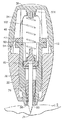
図1〜図3を参照すると、本発明の実施形態によるランセット装置10が、一般的に示される。ランセット装置10は、一般に、ハウジング12と、ハウジング12と移動可動に関連付けられたシールド14と、内部に配置されたランセット構造体70とを含む。ここにより詳細に説明されるように、シールド14は、ハウジング12と同軸に且つ移動可能に関連付けられ、ハウジング12内に部分的に配置され、ハウジング12から部分的に外方に延びており、ランセット構造体70は、シールド14内に含まれ、該シールド14を通って軸方向または長手方向に移動可能である。
With reference to FIGS. 1-3, a
ハウジング12は、細長い本体を定め、末端部分すなわち前端部分22を定める本体20と、基端部分すなわち後端部分26を定める後部キャップ24とを有するように形成されることが望ましい。ここにさらに詳細に説明されるように、ハウジング12の内部は、ほぼ開放され、内部キャビティ28を定めており、内部キャビティ28は、後部キャップ24により後端部で閉じられ、シールド14が延びる前端部22を貫通する開口部30を含む。本体20および後部キャップ24は、一体形成されることが可能である。代替的に、本体20および後部キャップ24は、互いに取り付けられてハウジング12を形成し、ランセット装置10の組み立てを助ける別個の要素である。このような実施形態の例において、図4A〜図4Eおよび図5A〜図5Eは、それぞれ本体20および後部キャップ24を示す。本体20および後部キャップ24は、適切な接着剤によって互いに取り付けられることが可能であり、あるいは、摩擦嵌合またはスナップ嵌合構成のような、これらの間に機械的取り付けを提供する相互係合構造を含むことができる。例えば、本体20は、環状溝32を定める環状リム31を含むことができ、後部キャップ24は、接合面に環状リップ34を有する環状突起部33を含むことができる。本体20および後部キャップ24が接合されたとき、環状突起部33が本体20の後部開放端内に延び、環状リップ34が、本体20の環状リム31の上に、且つ、環状溝32の中にスナップ嵌合する。このような要素の構成は、単に例示的なものであり、逆にできることが理解されるべきであり、また、他の相互係合構造を用いて、本体20を後部キャップ24と嵌合させ得ることが考えられる。代替的な実施形態において、本体20および後部キャップ24は、一体形成された構造体とすることができ、よって、1つの部品として一緒に成形することができる。
The
図11Bに示されるように、本体20および後部キャップ24によって定められる概ね長いハウジング12は、各々が、つまみ用陥凹部37、38のような、ユーザの指に適合させるための面を含むことができる反対方向を向いた側部35、36を有する。ハウジング12上に2つの反対方向を向いたつまみ用陥凹部37、38が設けられるが、本発明によると、ハウジング本体20に形成された1つのつまみ用陥凹部37だけを設け得ることが理解されるであろう。つまみ用陥凹部37は、ハウジング12の外面上の凹状窪みまたは凹部として形成されることが可能である。付加的に、後部キャップ24の上面のような、ハウジング12の後端部26を同様に凹状窪みまたは凹部として形成することもできる、後部つまみ用陥凹部39のような、ユーザの指に適合させるための面を含むこともできる。側部つまみ用陥凹部37、38および後部つまみ用陥凹部39は、実質的にユーザの指先に適合し、ユーザがランセット装置10を操作し、血液の抜き出し、抜き取り、または採取処置の際に該ランセット装置10を使用するのを助け、且つ、ユーザに多数のつまみ位置を提供することができる、人間工学的形状の面を提供する。図11Bに示されるように、側部つまみ用陥凹部37、38は、双曲線により形成された外形として表されることが可能である。例えば、双曲線は、主ハウジングを定める対称面とほぼ同一平面上にある場所で交差する2つの漸近線を含むことができる。付加的に、図11Bに示されるように、後部キャップ24は、双曲線により形成された外形を含むことができる。ハウジング12は、ユーザに視覚的および触覚的手がかりを与え、指先を置く場所をユーザに教えることができる、ハウジング12に沿って延び、該ハウジング12と一体形成された複数の長手方向リブ40およびトラフ41のような、ハウジング12とユーザの指先との間の把持を全体的に改善するための構造をさらに含むことができる。ハウジング12は、前端部22に配置された少なくとも1つの周辺陥凹部42を、随意的に2つまたはそれ以上の周辺陥凹部42をさらに含むことができる。1つの特定の実施形態において、全体が引用によりここに組み入れられる、発明者ブラッドリ・ウィルキンソンによる「ランセット装置」という名称の2004年11月30日に出願された特許文献7に開示された形状構成に従って、ランセット装置を構成することができる。
As shown in FIG. 11B, the generally
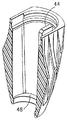
上述のように、シールド14は、ハウジング12の前端部を通って開口部30から外方に延びる。図6A〜図6Fに示されるように、シールド14は、前端部52と後端部54との間に延びるシールド本体50と、これらの間に延びる内部キャビティ56とを定めるほぼ円筒形で中空の構造体である。ここにより詳細に説明されるように、シールド本体50の前端部52は、ランセット装置10がユーザによって作動されたときに穿刺要素が延びる前部開口部60を含む前端壁58を定める。一般に、前端壁58は、穿刺要素によって穿刺されることになるユーザの身体上の意図される領域に接触するための小さな接触面積を末端開口部60の周りに定める。シールド14内に形成された複数の周辺陥凹部62を設けることによって、減少した接触面積をより小さくする(すなわち、面積を減少させる)ことができる。より詳細に説明されるように、周辺陥凹部62はまた、一般に、ユーザが、ランセット装置10の、特にランセットの穿刺要素のねらいをつけるのを視覚的に助けるターゲット指標を提供することもできる。周辺陥凹部62は、一般に、ハウジング12上に設けられた周辺陥凹部42に似ている。周辺陥凹部42は、シールド14の周囲の周りに配置され、該シールド14の周りに等間隔で配置されることが可能である。周辺陥凹部42は、ユーザが、穿刺要素の適切な送出点を視覚的に容易に特定することを可能にし、これによりランセット装置10の照準特性が改善され、皮膚穿刺操作の際に適切な血流が保証される。
As described above, the
述べられたように、シールド14は、ハウジング12内で軸方向または長手方向に移動可能である。したがって、シールド14およびハウジング12は、ハウジング12を通してシールド14を案内するための対応する案内面を含むことができる。例えば、シールド本体50は、外面に沿って延び、間に案内チャネル64を形成する一対の長手方向突起部63を含むことができる。ハウジング12は、案内チャネル64内に嵌合させるための、本体20内の案内タブ44のような対応する構造を含むことができる。シールド本体50は、反対方向を向いた側部に沿って長手方向に延びる一対の案内チャネル64を含み、ハウジング12は、案内チャネル64の各々に対応する本体20の対向する内面上にある一対の案内タブ44を含むことが望ましい。案内タブおよび案内チャネルの構成を逆にできること、および、他の案内面も使用できることが考えられる。案内タブ44および案内チャネル64は、シールド本体50がハウジング12内で適切に位置合わせされることを保証し、ハウジング12内でのシールド本体50の軸方向の摺動運動をもたらし、望ましくは回転運動を防止しまたは回転運動に抵抗する。付加的に、シールド本体50は、ハウジング12の本体20内での案内タブ44の上面との係合のために、後端部にレッジ66を含むことができる。代替的にまたはこれに加えて、シールド本体50は、前端部の方向に前方肩部69を含むことができ、ハウジング12の本体20は、前方リム面48を含むことができ、これらの間に係合をもたらす。こうした係合構造は、シールド本体50が、開口部30を通ってハウジング12の外に軸方向に完全に摺動することを防止する。
As stated, the
ハウジング12およびシールド14は、作動後、シールド14をハウジング12に対して固定関係状態に維持するために、これらの間に延びるロック構造をさらに含むことができる。例えば、シールド本体50は、本体20または後部キャップ24との摩擦係合または内部嵌合係合のために、後端部54の構造を含むことができる。例えば、シールド本体50は、後部キャップ24の内面内でのロック凹部29との内部嵌合係合のために、後端部54に延びるロック・フィンガ59を含むことができる。
The
ランセット装置10は、ハウジング12内に配置され、シールド14を通って延びるランセット構造体70をさらに含む。図7A〜図7Fに示されるように、ランセット構造体70は、前端部に穿刺端部74を定めるランセット72の形態で示される穿刺要素を含む。ランセット装置10の使用に関してここにさらに説明されるように、ランセット構造体70は、穿刺端部74がシールド本体50内に維持されている状態の最初の用意位置と穿刺端部74がシールド本体50の前部開口部60を超えて延びる穿刺位置との間で、シールド本体50の内部キャビティ56を通って軸方向または長手方向に移動するように適合される。
穿刺端部74は、患者の皮膚を穿刺するように適合され、先の尖った端部、刃先等を定めることができる。穿刺端部74は、ブレードの先の尖った端部が特定の配向に位置合わせされるといったような、好ましい位置合わせ配向を含むことができる。こうした実施形態において、シールド本体50および/またはハウジングの本体20は、穿刺端部74の位置合わせ配向に対応するターゲット指標を含むことができる。シールド本体50の陥凹部62および/または本体20の陥凹部42は、こうした位置合わせ配向として機能することができる。
The
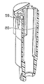
ランセット構造体70は、後端部にランセット72を支持するキャリア要素76をさらに含む。キャリア要素76およびシールド本体50は、ランセット構造体70を案内するための対応する案内面を含むことができる。例えば、キャリア要素76は、外面上に案内タブ78を含むことができ、シールド本体50は、案内タブ78を内部に摺動可能に適合させるための、内面に沿って長手方向に延びる対応する案内チャネル80を含む。キャリア要素76は、反対側を向いた側面上に一対の案内タブ78を含み、シールド本体50は、案内タブ78の各々に対応する、対向する内面に沿って延びる対応する対の案内チャネル80を含むことが望ましい。案内タブおよび案内チャネルの構成を逆にできること、および、他の案内面も使用できることが考えられる。案内タブ78および案内チャネル80は、ランセット構造体70がシールド本体50内で適切に位置合わせされることを保証し、シールド本体50内でのランセット構造体70の軸方向の摺動運動をもたらし、回転運動を防止しまたは回転運動に抵抗することができる。案内タブ78の底面81は、案内チャネル80の底面に押し当てて当接させるための当接面を提供し、ランセット構造体70が、前部開口部60を通ってシールド本体50の外に軸方向に完全に移動するのを防止する。
The
図10に示されるように、シールド本体50の後端部54に示される保持ハブ90が、さらに設けられる。保持ハブ90は、シールド本体50の後端部内に配置されるまたは保持される別個の構造体として設けられることが望ましい。例えば、シールド本体50は、後端部54の上面内に延びる凹部68のような、保持ハブ90を適合させるための構造を含むことができる。このように、保持ハブ90は、凹部68内に載っている。他の実施形態において、シールド本体50は、組み立てを助けるために保持ハブ90を支持し、位置決めするための面を含むことができる。さらに、本発明の他の実施形態において、保持ハブ90の機能要素をシールド本体50の上に直接成形することまたは形成することができる。
As shown in FIG. 10, a holding
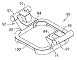
保持ハブ90は、ランセット構造体70を、ハウジング12内に後退された最初の用意位置に保持するためのレバー構造体を定める。特に、図8A〜図8Dに示されるように、保持ハブ90は、肩部94とその上面の接触面96とを含み、肩部94と接触面96との間の下面にピボット・ヒンジ98を有する、ピボット運動可能なレバー要素92を含む。一例として、レバー要素92は、シーソーのように、支点またはピボット点が力と荷重との間に配置されたクラス1のレバーを定める。例えば、レバー要素92の上面は、接触面96の反対側にある肩部94を含み、ピボット・ヒンジ98が、肩部94と接触面96との間の支点を提供する。このように、ここにより詳細に説明されるように、肩部94上にかかる、ランセット構造体70により代表される荷重が、接触面96に加えられる力から切り離され、ピボット・ヒンジ98の支点が力と荷重との間に配置される。
The holding
図8A〜図8Dに示されるように、1つの実施形態においては、ピボット運動可能な概ね楔形状の構造体として、レバー要素92が設けられ得、楔形のものの底部の点が、レバーのピボット運動のための、ピボット・ヒンジ98の支点として働く。保持ハブ90は、環状リム100を含むことができ、少なくとも1つのレバー要素92が、ピボット・ヒンジ98によって環状リム100上に支持され、かつ、これにピボット運動可能にヒンジ式に接続されている。保持ハブ90は、一般に、対向する側部において環状リム100の上面にピボット運動可能にヒンジ式に接続された一対のレバー要素92を含む。ここでは、環状リム100は、内部開口部を定めるように周方向または周辺に延びる、湾曲したコーナー接続部を有するほぼ矩形のリング状構造体として示される。ここに用いられる「環状」という用語は、湾曲したコーナー接続部または角のあるコーナー接続部を含む、円形のものであっても、湾曲したものであっても、または多角形のものであって、何らかのリング状構造体またはバンド状構造体を含むように意図される。不連続の環状構造体を有するスロット付き座金またはスリップオン座金に類似した構造体のような、他の環状のさらに不完全なリング状構造体またはバンド状構造体を用い得ることも考えられる。
As shown in FIGS. 8A-8D, in one embodiment, the
保持ハブ90およびランセット構造体70は、互いに係合状態にあるので、保持ハブ90は、ランセット構造体70を、ハウジング12内に後退された最初の用意位置に保持する。例えば、キャリア要素76は、そこから横方向に延びるフィンガ82を含むことができ、フィンガ82の底面上に支持面83を含むことができる。フィンガ82の支持面83は、レバー要素92の肩部94上に載り、これによりランセット構造体70と保持ハブ90との間に係止係合がもたらされる。
Since the holding
さらに、レバー要素92の接触面96は、ハウジング12内の構造体と接触係合するように適合される。例えば、ハウジング12の後部キャップ24は、一体形成され、少なくとも1つの、望ましくは2つの対向する内壁上に延びる内部接触部46のような、内部に延びる構造体を含むことができる。各々の内部接触部46は、カム面を形成する、レバー要素92の接触面96との接触係合のための係合面47を含む。1つの実施形態において、接触面96は、ほぼロッド形状部分97を含み、後部キャップ24の内面は、内壁面上におよび内壁面の各々の対向する側部上に互いに隣接するように延びる一対の内部接触部46を含む。このように、内部接触部46の対が、接触面96のロッド形状部分97の両端に係合し、これにより、レバー要素92のピボット運動の際、ロッド形状部分97の周囲の周りに連続的なカム状接触面が提供される。図8Eに示される代替的な実施形態において、接触面96は、上述のほぼロッド形状部分とは対照的に、面取り部分を形成する角度が付いた面197を含むことができる。角度が付いた面197により形成されたこのような面取り部分は、従来の射出成形手順で保持ハブ90を形成するための成形作業において特に有用である。このような実施形態を用いる場合には、後部キャップ24の内部接触部46の対が、接触面96の角度が付いた面197により形成された面取り部分の両側に係合し、上述のようなカム状接触面を提供する。
Further, the
さらに、レバー要素92は、一般に図8Dに面Yで示される面の一方の側に配置され、面Yは、ランセット装置10およびランセット構造体70の移動方向を全体的に定める一般的な長手方向軸Aに対する断面で環状リム100を切り裂く。このように、レバー要素92が外方にピボット運動するとき、ピボット・ヒンジ98により定められるもののような支点は、環状リム100の頂面のような面Yの上に低い断面二次モーメントを示し、レバー要素92の、すなわちピボット・ヒンジ98の塑性変形を引き起こす。こうした塑性変形は、恒久的なものであるので、レバー要素がピボット運動した後、レバー要素はその形状および位置を維持する。
Further, the
ランセット装置10を通るランセット構造体70の移動は、駆動ばね102により与えられる付勢力によって達成される。駆動ばね102は、ランセット構造体70に対して付勢力をかけ、該ランセット構造体70を装置を通して穿刺位置に向けて駆動するように適合され、ハウジング12の後端部とランセット構造体70との間に配置することができる。駆動ばね102は、ハウジング12の後端部とランセット構造体70との間に収納される別個の要素としてもよく、あるいは、ハウジング12および/またはランセット構造体70の一方または両方と一体形成されてもよい。後部キャップ24は、駆動ばね102を適切な配向に位置合わせおよび/または維持するための構造を含むことができる。例えば、後部キャップ24は、駆動ばね102に対応するための位置合わせナブ104を含むことができる。ランセット構造体70はまた、ランセット構造体70のキャリア要素76から延びる後部ナブ86のような、駆動ばね102の対向する端部に対応するための面または構造体を含むこともできる。駆動ばね102は、後部キャップ24の位置合わせナブ104とキャリア要素76の後部ナブ86との間に延びる。ランセット構造体70が作動状態位置にあるとき、駆動ばね102は、ハウジング12の後端部とランセット構造体70との間などに、ランセット構造体に対して力をかけ、ランセット構造体70を穿刺位置の方向に付勢する。シールド本体50およびレバー要素92は、駆動ばね102によってランセット構造体70および肩部94に対して加えられる付勢力に関係なく、レバー要素92がピボット・ヒンジ98の周りに反対方向にピボット運動するのを防ぐための相互係合構造を含むことができる。例えば、楔形状のレバー要素92から形成された底部の角度が付いた面99は、シールド本体50の後端部54上の対応する角度が付いたニブ55に係合し、これに当接することができる。こうした相互係合面は、駆動ばね102から加えられた何らかの力が、反対方向、すなわち肩部94がシールド本体50の内部キャビティ56内に下方にピボット運動する方向に、レバー要素92をピボット・ヒンジ98の周りにピボット運動させることを防止する。随意的にまたはそれに加えて、上述のようなピボット・ヒンジ98の塑性変形を恒久的なものとすることができ、これによりレバー要素92が反対方向に自動的にピボット運動されることが防止され、ランセット構造体70を、作動後に肩部94上にある作動前状態に再設定することが可能になる。
Movement of the
ランセット構造体70が穿刺位置に軸方向に移動された後にランセット構造体70をシールド本体50内に後退させるために、ランセット装置10の前端部に、さらに引き戻しばね110が設けられ得る。引き戻しばね110は、一般に、ランセット構造体70のキャリア要素76の前面88とシールド本体50の前端壁58内の内面との間に延びる。引き戻しばね110は、一般に、圧縮状態時にエネルギーを格納することができる圧縮ばねである。
In order to retract the
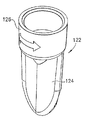
ランセット装置10は、使用前に該ランセット装置10を保護するように覆うための保護カバー120をさらに含むことができる。保護カバー120は、ランセット装置10の前端部と関連付けられたタブ部材122を含むことができ、シールド本体50の前端壁58の滅菌状態を維持する。図9A〜図9Fを参照すると、タブ部材122は、前方タブ部分124および垂下スカート126を含むことができる。垂下スカート126は、シールド本体50の前端部52と協働するように適合され、概ね前端部52を取り囲むまたは囲む。垂下スカート126は、ハウジング12の本体20の前端部22にも接触する。このように、タブ部材122は、本体20の前部開口部30およびシールド本体50の前部開口部60を取り囲む。さらに、こうした構成は、本体20およびシールド本体50のそれぞれの前端部を互いに対して固定関係状態に維持し、これによりランセット装置10の早すぎる作動を引き起こす運動が防止される。
The
保護カバー120の一部は、シールド本体50内に延び、穿刺要素の少なくとも一部を取り囲むことができる。例えば、図11Dに示されるように、柱部分130が、シールド本体50の前部開口部60を通って、内部キャビティ56内に延び、穿刺要素すなわちランセット72の少なくとも一部を保護するように囲み、かつ、取り囲む。柱部分130およびタブ部材122は、一緒に取り付けられるかまたは他の方法で保持される別個の要素とすることができる。例えば、タブ部材122は、柱部分130を収容するための内部開口部を含むことができる。図7A〜図7Eを全体的に参照すると、柱部分130をランセット構造体70のキャリア要素76と一体形成し、ランセット72を完全に取り囲むことができ、これにより使用前にランセット72の滅菌状態が保持される。柱部分130およびキャリア要素76はそれらの間の接合部にノッチ部分132を含むことができ、それは柱部分130を除去し、ランセット72を露出させるための破断点を提供する。代替的に、脱着可能な医療用グレード接着剤などを用いて、医療分野において慣例的な方法によって、柱部分130をランセット72に直接固定することもできる。
A portion of the
1つの実施形態において、後部キャップ24およびハウジング本体20は、ハウジング本体20がハウジング12の前部を形成し、後部キャップ24がハウジング12の実質的な後部を形成する、接合された別個の構造体である。より特定的には、後部キャップ24は、ハウジングおよび後部キャップの完全な長手方向長さによって一緒に測定されたとき、ハウジング12をほぼ半分に分割する位置でハウジング本体20と接合する、ハウジング12のほぼ半分といったハウジング12のかなり大きい部分を構成することができる。こうした構成は、シールド14、ランセット構造体70、並びに、保持ハブ90、駆動ばね102、および随意的に引き戻しばね110を含む保持要素および係合要素を含む内部部品を、その後端部からハウジング本体20内に挿入することができ、挿入のために小さなサイズのハウジング本体20によって隙間を形成する必要がほとんどないという点で、ランセット装置10の簡単化された組み立てを提供する。付加的に、このように挿入された後、全体のハウジング12に対して相対的に小さいサイズのハウジング本体20が提供する小さい隙間のために、こうした内部要素を容易に見ることができ、これにより適切な位置合わせを容易に視覚的に保証することが可能になる。さらに、次に、ハウジング12内の保持ハブ90のほぼ周囲の場所等の、内部機能部品に隣接した場所において、後部キャップ24をハウジング本体20に嵌合させることができる。また、ハウジング本体20および後部キャップ24は、ハウジング12の全長のほぼ中間点で接合することができ、各々がハウジング12の半分を実質的に定める。このように、ハウジング本体20および後部キャップ24の接合部が、つまみ用陥凹部37、38を実質的に横断するかまたは二等分する。
In one embodiment, the
本発明のランセット装置のそれぞれの要素は全て、一般に、医療用グレードのプラスチック材料のような成型プラスチック材料で形成される。ランセット72は、皮膚を穿刺するように適合されたいずれかの適切な材料から構成され得、一般的には、ステンレス鋼のような外科用グレード金属である。
All elements of the lancet device of the present invention are generally formed of a molded plastic material, such as a medical grade plastic material. The
ここで、全体的に図1〜図18を、特に図11Dおよび図12〜図18を参照して、ランセット装置10の使用が説明される。使用前、ランセット装置10は、前端部でシールド14を覆っている保護カバー120を有する状態で、図1および図11Dに示されるように提供される。ランセット装置10、特にランセット構造体70は、最初の作動前状態にあり、キャリア要素76のフィンガ82が、これと係合状態にあるレバー要素92の肩部94に当接しているか、または、この上に載っている。このように、保持ハブ90のレバー要素92は、ハウジング12内の作動前位置にランセット構造体70を維持し、特に穿刺端部74をシールド本体50内に後退された状態に維持する。さらに、駆動ばね102が、ランセット構造体70とハウジング12の後部キャップ24との間に延びている。この作動前位置において、駆動ばね102は、弛緩状態であってもよく、完全に圧縮された状態であってもよい。駆動ばね102は、この作動前位置において部分的に圧縮された状態にあり、後部キャップ24とランセット構造体70との間に付勢力をかけ、フィンガ82と肩部94との間の係合が、こうした付勢力に対抗してランセット構造体70を維持することがより望ましい。さらに、底部の角度が付いた面99と角度が付いたニブ55との間の相互係合面は、レバー要素92が、反対方向にピボット運動することを防止し、これによりランセット構造体76がシールド本体50の中を通して押し付けられる。また、この状態において、保護カバー120が、ハウジング12に対するシールド14のあらゆる軸方向の運動を防止し、これによりランセット装置10の作動が防止される。
The use of the
使用のためにランセット・アセンブリを準備するために、ユーザは、ハウジング12の反対側を向いた側部35、36を親指ともう1本の指の間などで把持し、図2に示されるように前端部から保護カバー120を取り除き、これによりハウジング12の本体20の前端部から延びているシールド本体50が露出される。パドル形状の部材を含ませるなど、タブ部材122の前方タブ部分124を人間工学的に形成し、ユーザが、タブ部材122を容易に操作し、必要な力またはトルクを加え、垂下スカートをシールド本体50の前端部との摩擦係合から解放し、ノッチ132において柱部分130をキャリア要素76から破断させることを可能にし、これによりランセット72から該柱部分130が解放され得る。加えられる破断力は、本発明に従ったものであり、柱部分130とキャリア要素76との間の結合を破断し、垂下スカート126とシールド本体50との間の摩擦係合を解除するように適用される、個々の捻れ動作または引っ張り動作とすることができ、あるいは組み合わされた「捻れ」(すなわち、回転)動作および「引っ張り」動作とすることができる。
To prepare the lancet assembly for use, the user grasps the
次に、シールド本体50の前端壁58は、図13に示されるような患者の皮膚の表面Sといった、血流を開始させることが望ましいユーザの身体、または別の人の身体上の場所と接触されることが可能である。設けられる場合には、陥凹部62のようなターゲット指標が所望の穿刺位置と位置合わせされ得る。
Next, the
身体に押し当てて配置されると、ユーザは、ハウジング12に下向きの力をかけ、シールド本体50を皮膚の表面Sに押し付ける。特に、ユーザは、後部キャップ24のつまみ用陥凹部39に矢印Xの方向の力を加え、これにより皮膚表面Sに力が加えられる。こうした力は、シールド本体50の前端壁58とハウジング12の後部キャップとの間に対向する外圧を確立し、シールド本体50をハウジング12内に軸方向に移動させ、これによりシールド本体の後端部54が後部キャップ24の方向に移動される。案内タブ44および案内チャネル64によって提供される対応する案内面は、シールド本体50を、ハウジング12の本体20を通して軸方向に案内し、これらの間に適切な軸方向の位置合わせを保証する。
When placed against the body, the user applies a downward force to the
保持ハブ90はシールド本体50の後端部54に隣接しているので、後部キャップ24の方向へのシールド本体の後端部54のこうした移動は、後部キャップ24の方向への保持ハブ90の対応する後方移動を引き起こす。さらに、保持ハブ90のレバー要素92の肩部94とランセット構造体70のキャリア要素76のフィンガ82との間の係合は、後部キャップ24の方向へのランセット構造体70の対応する後方移動を引き起こす。こうした運動により、駆動ばね102が圧縮される。最初の作動前位置において駆動ばね102が弛緩状態にある実施形態において、駆動ばね102のこの圧縮は、シールド本体50を通してランセット構造体70を穿刺位置まで軸方向前方に推進するのに十分な付勢力を有するように駆動ばね102を作動状態にし、これによりランセット構造体70が用意位置に与えられる。しかしながら、この時点で、ランセット構造体70は、フィンガ82と肩部94との間の係合のために、穿刺端部74がシールド本体50内に引っ込められるように依然として維持されている。最初の作動前位置において駆動ばね102が部分的に圧縮された状態にある実施形態において、この駆動ばね102の圧縮は、シールド本体50を通してランセット構造体70を穿刺位置まで軸方向前方に完全に推進するのに十分な付加的な付勢ポテンシャルエネルギーを有するように、駆動ばね102をさらに作動状態にする。また、この作動前の用意位置において、ランセット構造体70は、フィンガ82と肩部94との間の係合に基づいて、穿刺端部74がシールド本体50内に後退されるように依然として維持される。
Since the
このような後部キャップ24の方向へのシールド本体50の軸方向または長手方向の移動中、キャリア要素76のフィンガ82がレバー要素92の肩部94上に載った状態で、保持ハブ90も後部キャップ24に向けて後方方向に(または基端方向に)移動される。図13〜図14に示されるように、こうした保持ハブ90の後方方向の移動により、後部キャップ24内の内部接触部46の係合面47のカム面が、ロッド形状部分97のようなレバー要素92の対応する接触面96と係合し、協働する。したがって、対応するカム接触面が、ランセット装置10のための作動要素を提供する。レバー要素92の楔形状プロファイルのために、こうした係合および協働により、レバー要素92が、環状リム100に対してピボット・ヒンジ98周りにピボット運動する。特に、概ね環状リム100の半径方向内方に延びる肩部94および概ね環状リム100の外周辺上にある接触面96については、係合面47は、環状リム100の外周辺において接触面96、特にロッド形状部分97に係合し、これにより接触面96および肩部94が傾くまで、レバー要素92がピボット・ヒンジ98の支点の周りにピボット回転され、ランセット構造体が、環状リム100を通して、シールド本体50の内部キャビティ56内に解放される。
During such axial or longitudinal movement of the
こうした係合によりランセット装置の作動が与えられる。特に、ピボット・ヒンジ98の周りのレバー要素92のピボット運動により、肩部94が後部キャップ24の後端部の方向にさらに移動され、これにより駆動ばね102がさらに圧縮され、さらに付勢される。引き続きシールド本体50を後部キャップ24の方向に軸方向に移動させることにより、内部接触部46および接触面96の対応する面がさらに係合され、係合面47がロッド形状部分97の周囲に来るようにまたは載るようになり、これによりレバー要素92がさらにピボット運動する。最終的に、図15〜図16に示されるように、こうしたピボット運動により、肩部94とキャリア要素76のフィンガ82との間の係合が解除される点まで、肩部94がピボット運動される。この時点で、フィンガ82は肩部94から自由になり、環状リム100を貫通する内部開口部を通って軸方向に移動できるようになる。駆動ばね102の付勢力により、ランセット構造体70は、ハウジング12およびシールド本体50を通して後部キャップ24から遠ざかるように軸方向下方に推進される。こうした移動の間、対応する案内タブ78および案内チャネル80が、シールド本体50を通してランセット構造体70を軸方向に案内する。さらに、こうした軸方向の移動の間、シールド本体50は、ランセット構造体70のフィンガ82と位置合わせされ、これを摺動関係状態に引き入れるように適合された付加的なチャネルをさらに含むことができる。
Such engagement provides operation of the lancet device. In particular, the pivoting movement of the
したがって、レバー要素92のピボット運動をもたらす係合面47と接触面96との間の圧迫係合接触またはカム係合接触によって、ランセット装置10の作動が達成される。記載されたように、こうしたピボット運動は、ランセット構造体70を作動状態またはさらに作動状態にするための駆動ばね102の圧縮と、ランセット構造体70を作動前位置すなわち用意位置に維持する係合の連続的な解除の両方をもたらす。したがって、装置の単一の動きによって、ランセット装置10の作動が、ランセット構造体を連続的に作動状態にすることとそれを解放することとを達成する。さらに、こうして連続的に作動状態にし、解放することは、ハウジング12とピボット運動可能なレバー要素92との間の相互係合する接触面の動きを必要とするだけである。したがって、互いに対する相互係合面の動きのための何らかの機構が与えられる限り、軸方向に移動可能なシールドが含まれているかどうかに関係なく、こうした連続的な作動状態にすることと解放することとを達成できることが考えられる。
Thus, operation of the
例えば、図19は、本発明の代替的な実施形態におけるランセット装置10aの断面図を示す。この実施形態において、押しボタン25aのような作動要素を含むアクチュエータによって作動が達成される。特に、ハウジング12aが、本体20aおよび後部キャップ24aによって定められる。押しボタン25aは、後部キャップ24aにおいてハウジング12aを通って、内部の内部キャビティ28a内に延びる。押しボタン25aをハウジング12a内に軸方向に移動させることによって、ハウジング12a内の押しボタン25aの前端部にある1つまたは複数の係合面47aが、レバー要素92aの対応する接触面96aに接触し、これによりレバー要素92aが、ピボット・ヒンジ98aの周りにピボット運動されるような具合に、ランセット装置10aの作動が達成される。前述の実施形態におけるように、こうした接触およびピボット運動が、キャリア要素76aの支持面83aとレバー要素92aの肩部94aとの間の係合を解除し、これにより、駆動ばね102aがハウジング12aを通してランセット72aを穿刺位置に推進することが可能になる。押しボタン25a内の位置合わせナブ104aによって、駆動ばねをキャリア要素76aと押しボタン25aとの間に保持することが可能である。代替的に、駆動ばねをキャリア要素とハウジングの後端部との間に保持し、押しボタン要素がハウジングを通って延び、ピボット運動を引き起こすことができる。
For example, FIG. 19 shows a cross-sectional view of a lancet device 10a in an alternative embodiment of the present invention. In this embodiment, actuation is accomplished by an actuator that includes an actuation element such as push button 25a. In particular, the housing 12a is defined by the body 20a and the rear cap 24a. The push button 25a extends through the housing 12a in the rear cap 24a and into the internal cavity 28a. By axially moving the push button 25a into the housing 12a, one or
図17に示されるような作動を参照すると、駆動ばね102の付勢力により、ランセット構造体70がシールド本体50を通して穿刺位置にまで推進され、ランセット72の穿刺端部74は、該穿刺端部74が皮膚表面Sを穿刺することを可能にするのに十分な距離、前端壁58を通る前部開口部60を通って延びる。シールド本体50内の案内チャネル80の底面81は、このような推進中、ランセット構造体70が前部開口部60を通ってシールド本体50の外に完全に軸方向に移動するのを防ぐための案内タブ78のための当接面を提供する。さらに、こうした推進中、キャリア要素76の前面88が、引き戻しばね110の後端部に接触し、シールド本体50の前端部52内に、望ましくはランセット装置の作動前状態および/または用意状態における弛緩された状態に保持される。駆動ばね102の付勢による推進力が、引き戻しばね110とのこうした接触を引き起こし、これにより引き戻しばね110を、ランセット構造体70の前面88とシールド本体50の前端壁58の内部との間で圧縮する。引き戻しばね110の構造は、ランセット構造体70を推進する駆動ばね102の付勢力に基づいて圧縮可能であり、ランセット72の穿刺端部74が前部開口部60を通って延びることを可能にするように設計される。さらに、引き戻しばね110は圧縮ばねであり、よって、このように圧縮可能であり、ランセット構造体70が穿刺位置まで延びた後に弛緩状態に戻るのに十分な弾性を含む。したがって、駆動ばねがランセット構造体70を穿刺位置に駆動した後、弛緩状態にあるときのシールド本体50の前端壁58とランセット構造体70との間の圧縮ばね110の付勢力は、ハウジング12の後部キャップ24とランセット構造体70の後部ナブ86との間に作用する駆動ばね102の付勢力を上回る。このように、引き戻しばね110は、圧縮されていない状態にまで緩められ、よって、ランセット構造体70の前面88と前端壁58の内面との間に付勢力を加え、これによりランセット構造体70が後部キャップ24に向けて後方に押しやられる。こうした付勢力が、前部開口部60を通しての露出からランセット72の穿刺端部74が遮蔽される位置に、シールド本体50内にランセット72の穿刺端部74を後退させる。さらに、駆動ばね102と引き戻しばね110との間に作用する対向する力、および、それらの構造に基づいたこうしたばねのそれぞれの力は、穿刺端部74がシールド本体50内に遮蔽された状態でハウジング12内に配置されたランセット構造体70を保持し、ランセット構造体70が穿刺位置にさらに移動することを防止する。
Referring to the operation shown in FIG. 17, the
さらに、ランセット装置の作動後、つまり、穿刺位置の後にランセット構造体70がハウジング12内に後退された後、シールド本体50およびハウジング12を固定関係状態にロックすることができる。特に、シールド本体50が後部キャップ24に向けて軸方向に移動された場合、ロック・フィンガ59が撓んで、それぞれの凹部29内にロックし、これによりシールド本体50が後部キャップ24およびハウジング12に対して後方の位置にロックされる。したがって、ランセット装置10は、再使用されないように安全に保護され、適切な医療用ごみ容器内などに適切に廃棄されることが可能である。
Furthermore, after the lancet device is actuated, that is, after the
図20〜図22を参照すると、ランセット装置は、保持ハブ90iの修正されたバージョンを含むことができる。図20は、保持ハブ90iを上述のようなランセット装置10の一部として示し、図20〜図22に示される同様の参照番号が図1〜図18と関連して説明された同様の要素を指す。保持ハブ90iは、一般に、環形状を定め、ランセット構造体70を、本体20および後部キャップ24によって定められるハウジング内に後退される最初の用意位置に維持するように適合される。保持ハブ90iは、典型的に、2つのピボット運動可能なカム要素92iによって接続された2つの対向する細長い支持部材91iを含み、保持ハブ90iの環形状を形成する。カム要素92iの各々は、対向する支持部材91iとピボット運動可能に係合された2つの外方に延びるシャフト93iを含む。カム要素92iの各々は、上面に上側接触面96iを定める、少なくとも1つの典型的な楔形状の接触要素94iをさらに含む。カム要素92iの各々は、底部側に定められた、ほぼ中央に配置された凹部またはカットアウト100iをさらに定める。凹部100iの目的は、ランセット装置10における保持ハブ90iの作動と関連してここに説明される。図21Aおよび図22に示されるように、カム要素92iの各々は、カム要素92iのほぼ両端に配置された2つの接触要素94iを含み、凹部100iが、接触要素94i間のカム要素92iの底部側に定められることが望ましい。
20-22, the lancet device can include a modified version of the retention hub 90i. FIG. 20 shows the retaining hub 90i as part of the
この実施形態のランセット装置において、保持ハブ90iおよびランセット構造体70は、互いに係合状態にあるので、保持ハブ90iは、ランセット構造体70を、ハウジング内に後退される最初の用意状態に保持する。例えば、キャリア要素76上のフィンガ82は、カム要素92iの上側に載っており、これによりランセット構造体70と保持ハブ90iとの間に係合が提供される。さらに、接触要素94i上の上側接触面96iは、ハウジング内の構造体と接触係合するように適合されることが可能である。例えば、後部キャップ24は、一体形成され、少なくとも1つの内部側壁上、望ましくは2つの対向する内部側壁上に延びる内部接触部46のような、内部に延びる構造体を含むことができる。保持ハブ90iは、一般に、各カム要素92i上に2つの接触要素94iを含むので、上述された接触部46のような2つの内部接触部を、ハウジングの2つの対向する内部側壁上に設けることができる。各々の内部接触部は、接触要素94i上の対応する接触面96iとの接触係合のための、上述されたカム面47のような末端方向の係合カム面を含む。
In the lancet device of this embodiment, since the holding hub 90i and the
図20〜図22のランセット装置の通常の作動において、後部キャップ24の方向へのシールド本体50の軸方向または長手方向の移動により、キャリア要素76のフィンガ82がカム要素92i上に載った状態で、保持ハブ90iが後部キャップ24に向けて後方に移動される。保持ハブ90iのこうした後方移動により、後部キャップ24内の内部接触部の係合カム面の接触面が、カム要素92iの接触要素94i上の対応する接触面96iに係合し、これと協働するようになる。内部接触部がこのように係合し、引き続き下方または末端方向に移動することにより、カム要素92iが、支持部材91iに対してシャフト93i上でピボット運動するかまたはシャフト93iの周りを回転する。接触要素94iの一般的な楔形状プロファイルのため、カム要素92iのピボット運動は、少なくともキャリア要素76上の後部ナブ86が後部キャップ24の内側に接触するまで、フィンガ82をさらに「持ち上げること」によって駆動ばね102をさらに圧縮する効果を有する。この時点で、シールド本体50を後部キャップ24に向けて軸方向または長手方向に移動し続けることにより、カム要素92iが、該カム要素92iの底部側に定められた凹部100iがフィンガ82とほぼ位置合わせされた位置にピボット運動され、この時点でフィンガ82とカム要素92iとの間の係合が、このような位置合わせにより解除される。次に、駆動ばね102の付勢力が、ランセット構造体70を、後部キャップ24から遠ざかるように、ハウジングおよびシールド50を通して軸方向に、かつ、保持ハブ90iによって定められる環状開口部を通して軸方向に、下方に推進する。
In normal operation of the lancet device of FIGS. 20-22, with the axial or longitudinal movement of the
図23A〜図23Dを参照すると、更に別の実施形態において、一般に、ランセット装置の更に別の変形または修正が示される。図23A〜図23Dの実施形態において、ランセット装置200の形態の穿刺装置が示される。ランセット装置200は、一般に、ハウジング211と、該ハウジング211内に部分的に受けられ、該ハウジング211に対して軸方向に移動可能なシールド213と、該ハウジング211内に配置された皮膚穿刺アセンブリ215(上述されたランセット構造体70に類似したものにすることができる)とを含む。ハウジング211は、末端部216および基端部218を有するほぼ管状構造体であることが好ましく、本体20および後部キャップ24を含む、図1〜図18と関連して上述されたハウジング12に類似した構造体を含むことができる。ハウジング211は、末端部216および基端部218が開いていることが望ましい。ハウジング211の基端部218を閉じるように、該ハウジング211の基端部218にエンドキャップ240を設けることができる。代替的に、ハウジング211は、エンドキャップ240の代わりに閉じられた基端部218を有するように形成することができる。こうした実施形態において、ハウジング211の閉じられた基端部218は、穿刺装置200のこの変形におけるハウジング211の本体の残りと一体形成される。皮膚穿刺アセンブリ215は、キャリア部材250に接続された保護先端ガード282をさらに含むことができる。先端ガード282は、キャリア部材250の本体と一体形成することができ、上述された保護カバー120と同じようにキャリア部材250とノッチ式に接続することができる。
Referring to FIGS. 23A-23D, in yet another embodiment, generally further variations or modifications of the lancet device are shown. In the embodiment of FIGS. 23A-23D, a lancing device in the form of a
撓み部材238が、シールド213の基端部244上に形成されるまたは設けられる。撓み部材238は、図1〜図19と関連して前に述べられた実施形態のピボット・レバー要素および保持ハブと同じように作用する、ランセット構造体をハウジング内に後退される最初の用意位置に保持するための構造体を定める。例えば、撓み部材238上の突起部276は、皮膚穿刺アセンブリ215のキャリア部材250と係合または協働するように内方に延びる。突起部276は、キャリア部材250に定められたまたは形成された周方向凹部200に係合するかまたは周方向凹部200内に延びる。この凹部210は、撓み部材238の突起部276により係合される周方向縁部212を定める。図23A〜図23Dに示されるランセット装置210内の突起部276の係合縁部277が、各々の突起部276上の半径方向内方に延びるタブ214によって形成されるまたは定められる。係合縁部277は、図1〜図18に関連して上述された肩部94と同様の方法で作用し、皮膚穿刺アセンブリ215によって代表される荷重が係合縁部277にかかっている。
A
突起部276は、ハウジング211内へのシールド213の軸方向の移動によってキャリア部材250との係合が解除されるまで、キャリア部材250、よって皮膚穿刺アセンブリ215を、後退位置に維持する。ランセット装置200の作動前状態において、駆動ばね270の付勢力は、突起部276によって、および、ハウジング211の末端部216に設けられた干渉構造体とのシールド213の末端部242の係合によって抑制される。特に、シールド213はハウジング211内に軸方向または長手方向に運動可能または移動可能であるが、シールド213は、該シールド213上に形成された縁部217によって、ハウジング211に対する末端方向の移動が防止されている。縁部217は、増大した壁厚を有するシールド213の部分219によって形成されるまたは定められる。縁部217は、ハウジング211の末端部216に形成された内部リップ220と協働またはこれに係合し、駆動ばね270の力を抑制する。リップ220との縁部217の係合により、撓み部材238がキャリア部材250を後退位置に維持し、駆動ばね270の力を抑制することが可能になる。特に、ランセット装置200の作動前状態において、駆動ばね270の力は、突起部276を介してシールド213の本体に伝えられ、これによりシールド213上の縁部217がリップ220に係合され、駆動ばね270の力が抑制されるようになる。
The
撓み部材238は、1つまたは複数の(図1〜図18に関連して上述された実施形態における内部接触部46と類似した)作動部材222によってキャリア部材250との係合が解除されるように適合される。作動部材222は、エンドキャップ240と一体形成されてもよく、またはエンドキャップ240とは別個に形成され、例えば、接着剤を用いてエンドキャップ240に固定されてもよい。作動部材222は、穿刺装置200を作動するために、撓み部材238のテーパ状カム面278と協働または係合するように適合された(係合面47に類似した)テーパ状カム面224を含む。特に、図23A〜図23Dに示される穿刺装置200を作動させるために、ユーザ、一般的には医師は、シールド213の末端部242を、血液サンプルが採取される身体部分と接触状態に配置し、図23A〜図23Dの矢印226の方向に圧力をかけ、シールド213をハウジング211内に基端方向に移動させる。ハウジング211内へのシールド213の移動により、撓み部材238および作動部材222上の対向するカム面278、224がそれぞれ係合し、相互に作用する。図23Cおよび図23Dに示されるように、シールド213がハウジング211内に移動されるまたは動かされるにつれて、対向するカム面278、224の相互作用のために、撓み部材238が、半径方向外方に曲げられる。撓み部材238は、所定の距離、回転角度、または量だけ半径方向外方に撓むと、曲がるまたは破断するように適合または構成することができる。例えば、撓み部材238は、スコア・ラインのような脆弱領域228を有するように形成され、撓み部材238は、所定の距離または一定の回転だけ半径方向外方に撓んだときに破断するようにできる。さらに、脆弱領域228は、上述されたピボット・ヒンジ98と同じようにヒンジとして働くことができる。
The deflecting
撓み部材238のこうした運動中、突起部276は、後部エンドキャップ240の方向に傾斜し、これによりキャリア部材250が後部エンドキャップ240の方向に「持ち上げられ」または移動され、駆動ばね270が圧縮または更に圧縮される。撓み部材238上の突起部276がキャリア部材250との係合から解除されると、駆動ばね270は、キャリア部材250を後退位置から穿刺位置まで自由に移動させることができる。一旦撓み部材238がキャリア部材250との係合から解除されると、駆動ばね270は、皮膚穿刺要素215の鋭利な末端先端部254が人または動物の皮膚を穿刺するのに十分に蓄えられたエネルギーを有することが好ましい。
During such movement of the
キャリア部材250が末端方向に移動し、皮膚穿刺要素215の鋭利な末端先端部254が完全に露出される穿刺位置に達すると、図1〜図18を参照して上述された引き戻しばね110と同じように、引き戻しばね274が、キャリア部材250とシールド213の末端部242との間に圧縮される。引き戻しばね274の圧縮は、キャリア部材250に作用し、ハウジング211において該キャリア部材250を戻り方向、基端方向、または後退方向に移動させる戻し力または引き戻し力をもたらし、皮膚穿刺要素215および鋭利な末端先端部254をハウジング211およびシールド213内に完全に戻すまたは後退させる。その後、引き戻しばね274は、ハウジング211およびシールド213からの皮膚穿刺要素215の再出現を防止する。
When the
ランセット装置の特定の実施形態が説明されたが、当業者であれば、本発明の範囲および精神を逸脱することなく、修正および変更をなすことができる。したがって、上記の詳細な説明は、制限ではなく例証となるように意図される。本発明は、添付の特許請求の範囲によって定められ、特許請求の範囲の等価物の意味および領域の範囲に含まれる本発明に対する全ての変更はそれらの範囲に含まれるべきである。 While specific embodiments of a lancet device have been described, those skilled in the art can make modifications and changes without departing from the scope and spirit of the invention. Accordingly, the above detailed description is intended to be illustrative rather than limiting. The invention is defined by the appended claims, and all changes to the invention that fall within the meaning and range of equivalency of the claims are to be embraced within their scope.
Claims (39)
前記ハウジングの前記前端部の前記開口部を通して移動可能なシールドであって、シールドの後端部に隣接し、ピボット運動可能なレバーを有する保持ハブを含むシールドと、
穿刺要素を含むランセット構造体であって、前記ハウジング内に配置され、前記穿刺要素が該ハウジング内に配置される作動前位置と該穿刺要素が該シールドの前端部を通って延びる穿刺位置との間で移動するように適合され、ランセット構造体は該シールドの前記後端部において前記保持ハブの前記レバーと係合状態にあり、ランセット構造体が後退される位置に維持されるようになる、ランセット構造体と、
前記保持ハブの前記レバーに対して前記ランセット構造体を付勢するための、前記ハウジングと前記ランセット構造体との間に配置された駆動ばねと、
を備え、
前記ハウジングの前記後端部の方向への前記シールドの移動により、該ハウジング内の内部接触部が前記保持ハブの前記レバーに係合し、これにより該レバーのピボット運動を生じさせ、前記ランセット構造体を該レバーとの係合から解放し、前記駆動ばねが該ランセット構造体を、該シールドを通して前記穿刺位置の方向に駆動することが可能になることを特徴とするランセット装置。 A housing having a rear end and a front end having a front end and an opening extending therethrough;
A shield movable through the opening at the front end of the housing, the shield including a retaining hub adjacent to the rear end of the shield and having a pivotable lever;
A lancet structure including a piercing element, wherein the lancet structure is disposed within the housing, wherein the puncture element is disposed within the housing, and a puncture position where the puncture element extends through the front end of the shield. The lancet structure is engaged with the lever of the holding hub at the rear end of the shield so that the lancet structure is maintained in a retracted position. A lancet structure;
A drive spring disposed between the housing and the lancet structure for biasing the lancet structure against the lever of the holding hub;
With
The movement of the shield in the direction of the rear end of the housing causes the internal contact portion in the housing to engage the lever of the holding hub, thereby causing the lever to pivot, and the lancet structure. A lancet device, wherein the body is released from engagement with the lever and the drive spring allows the lancet structure to be driven through the shield in the direction of the puncture position.
穿刺要素を含むランセット構造体であって、前記ハウジング内に配置され、前記穿刺要素が該ハウジング内に保持される作動前位置と該穿刺要素が該ハウジングの前端部を通って延びる穿刺位置との間で移動するように適合されたランセット構造体と、
前記ランセット構造体を前記穿刺位置の方向に付勢する駆動ばねと、
前記駆動ばねの前記付勢に対抗して前記ランセット構造体を前記作動前位置に保持する保持ハブであって、支点の周りにピボット運動可能であり、該ランセット構造体との係合をもたらすレバーを含む保持ハブと、
前記レバーを前記支点の周りにピボット運動させ、該レバーを前記ランセット構造体との係合から解放し、前記駆動ばねが該ランセット構造体を前記穿刺位置の方向に駆動することを可能にするように適合されたアクチュエータと、
を備え、
前記前部ハウジング本体および前記後部ハウジング本体は、前記ハウジング内の前記保持ハブのほぼ周辺部にある位置で接合することを特徴とするランセット装置。 A housing including a front housing body and a rear housing body;
A lancet structure including a piercing element, wherein the lancet structure is disposed within the housing, the pre-operation position where the puncture element is held in the housing, and a puncture position where the piercing element extends through the front end of the housing A lancet structure adapted to move between,
A drive spring that biases the lancet structure in the direction of the puncture position;
A holding hub that holds the lancet structure in the pre-actuated position against the bias of the drive spring, the lever being pivotable about a fulcrum and providing engagement with the lancet structure A holding hub including:
Pivoting the lever about the fulcrum, releasing the lever from engagement with the lancet structure, and allowing the drive spring to drive the lancet structure in the direction of the puncture position An actuator adapted to
With
The lancet device is characterized in that the front housing main body and the rear housing main body are joined at a position substantially in the periphery of the holding hub in the housing.
前記ハウジング内で軸方向に移動可能であり、該ハウジング内に保持される穿刺要素を含むランセットであって、前記穿刺要素が該ハウジングの前端部を通って延びる穿刺位置の方向に移動可能なランセットと、
前記ハウジングの前端部を通って延びており、該ハウジングに対して移動可能なシールドと、
支点の周りにピボット運動可能な少なくとも1つのクラス1タイプのレバーを含む環状保持ハブであって、前記レバーは、ハブが前記シールドに対して前記ランセットの移動を制限する、前記支点に対する第1の位置と、該ハブが該シールドに対して該ランセットの移動を制限せず、該ランセットが該シールドの前記前端部を通って穿刺位置を達成することを可能にする第2の位置とを有する、環状保持ハブと、
を備え、
前記ハウジングに対する前記シールドの移動が、前記第1の位置から前記第2の位置までの前記レバーの移動を引き起こし、前記ランセットが該レバーとの係合から解放されることを特徴とするランセット装置。 A housing;
A lancet that is axially movable within the housing and includes a piercing element retained within the housing, wherein the piercing element is movable in the direction of a puncture position that extends through the front end of the housing. When,
A shield extending through the front end of the housing and movable relative to the housing;
An annular retention hub including at least one class 1 type lever pivotable about a fulcrum, wherein the lever restricts movement of the lancet relative to the shield, the first relative to the fulcrum. A second position that allows the hub to achieve a puncture position through the front end of the shield without restricting movement of the lancet relative to the shield. An annular retaining hub;
With
The lancet device, wherein movement of the shield relative to the housing causes movement of the lever from the first position to the second position, and the lancet is released from engagement with the lever.
Applications Claiming Priority (8)
| Application Number | Priority Date | Filing Date | Title |
|---|---|---|---|
| US56942404P | 2004-05-07 | 2004-05-07 | |
| US60/569,424 | 2004-05-07 | ||
| US63179504P | 2004-11-30 | 2004-11-30 | |
| US63184604P | 2004-11-30 | 2004-11-30 | |
| US60/631,846 | 2004-11-30 | ||
| US60/631,795 | 2004-11-30 | ||
| US66927605P | 2005-04-07 | 2005-04-07 | |
| US60/669,276 | 2005-04-07 |
Related Parent Applications (1)
| Application Number | Title | Priority Date | Filing Date |
|---|---|---|---|
| JP2007511614A Division JP4857263B2 (en) | 2004-05-07 | 2005-05-06 | Contact-operated lancet device |
Related Child Applications (1)
| Application Number | Title | Priority Date | Filing Date |
|---|---|---|---|
| JP2014203380A Division JP2014240030A (en) | 2004-05-07 | 2014-10-01 | Contact activated lancet device |
Publications (2)
| Publication Number | Publication Date |
|---|---|
| JP2011104398A JP2011104398A (en) | 2011-06-02 |
| JP5713708B2 true JP5713708B2 (en) | 2015-05-07 |
Family
ID=34969059
Family Applications (6)
| Application Number | Title | Priority Date | Filing Date |
|---|---|---|---|
| JP2007511614A Active JP4857263B2 (en) | 2004-05-07 | 2005-05-06 | Contact-operated lancet device |
| JP2011018990A Active JP5713708B2 (en) | 2004-05-07 | 2011-01-31 | Contact-operated lancet device |
| JP2014203380A Pending JP2014240030A (en) | 2004-05-07 | 2014-10-01 | Contact activated lancet device |
| JP2016030422A Active JP6306622B2 (en) | 2004-05-07 | 2016-02-19 | Contact-operated lancet device |
| JP2016239783A Active JP6511426B2 (en) | 2004-05-07 | 2016-12-09 | Contact-operated lancet device |
| JP2017224948A Active JP6463824B2 (en) | 2004-05-07 | 2017-11-22 | Contact-operated lancet device |
Family Applications Before (1)
| Application Number | Title | Priority Date | Filing Date |
|---|---|---|---|
| JP2007511614A Active JP4857263B2 (en) | 2004-05-07 | 2005-05-06 | Contact-operated lancet device |
Family Applications After (4)
| Application Number | Title | Priority Date | Filing Date |
|---|---|---|---|
| JP2014203380A Pending JP2014240030A (en) | 2004-05-07 | 2014-10-01 | Contact activated lancet device |
| JP2016030422A Active JP6306622B2 (en) | 2004-05-07 | 2016-02-19 | Contact-operated lancet device |
| JP2016239783A Active JP6511426B2 (en) | 2004-05-07 | 2016-12-09 | Contact-operated lancet device |
| JP2017224948A Active JP6463824B2 (en) | 2004-05-07 | 2017-11-22 | Contact-operated lancet device |
Country Status (13)
| Country | Link |
|---|---|
| EP (3) | EP2135551B1 (en) |
| JP (6) | JP4857263B2 (en) |
| KR (1) | KR101121072B1 (en) |
| CN (3) | CN101711678B (en) |
| AT (2) | ATE446048T1 (en) |
| AU (5) | AU2005244184B2 (en) |
| BR (1) | BRPI0510755B8 (en) |
| CA (1) | CA2565796C (en) |
| DE (1) | DE602005017263D1 (en) |
| ES (6) | ES2335113T3 (en) |
| MX (3) | MX365090B (en) |
| PL (3) | PL1755456T3 (en) |
| WO (1) | WO2005110227A1 (en) |
Families Citing this family (39)
| Publication number | Priority date | Publication date | Assignee | Title |
|---|---|---|---|---|
| US9380975B2 (en) * | 2004-05-07 | 2016-07-05 | Becton, Dickinson And Company | Contact activated lancet device |
| ATE410955T1 (en) * | 2006-04-13 | 2008-10-15 | Haemedic Ab | LANCET DEVICE FOR POINTING THE SKIN |
| JP5015613B2 (en) * | 2007-01-18 | 2012-08-29 | ”ハーテーエル−ストレファ“ スポールカ アクシーナ | Lancet device for skin puncture |
| PL213006B1 (en) * | 2007-04-19 | 2012-12-31 | Htl Strefa Spolka Akcyjna | Device for needling of patient's skin |
| EP2205153B1 (en) | 2007-10-08 | 2017-04-19 | Roche Diabetes Care GmbH | Analysis system for automatic skin prick analysis |
| WO2009148133A1 (en) * | 2008-06-05 | 2009-12-10 | 株式会社ライトニックス | Puncture needle cartridge and puncture device |
| JP5486183B2 (en) | 2008-12-08 | 2014-05-07 | テルモ株式会社 | Puncture device |
| US8262685B2 (en) | 2009-03-27 | 2012-09-11 | Nipro Corporation | Disposable lancing device |
| KR101147534B1 (en) * | 2009-06-02 | 2012-05-21 | 주식회사 인포피아 | Device for collecting body fluid |
| US8317812B2 (en) | 2009-07-29 | 2012-11-27 | Wah Leong Lum | Lancet device with lance retraction |
| EP2486852B1 (en) * | 2009-10-07 | 2014-04-09 | Asahi Polyslider Company, Limited | Lancing device |
| EP2382921A1 (en) * | 2010-04-30 | 2011-11-02 | Roche Diagnostics GmbH | Lancing device with automatic disengagement |
| JP5514008B2 (en) | 2010-06-22 | 2014-06-04 | ニプロ株式会社 | Disposable puncture device |
| JP5615125B2 (en) * | 2010-10-15 | 2014-10-29 | 株式会社旭ポリスライダー | Lancet lancing device |
| GB2487188A (en) * | 2011-01-07 | 2012-07-18 | Owen Mumford Ltd | Blood sampling device with trigger locking arrangement and method of assembly |
| KR101361112B1 (en) * | 2011-07-26 | 2014-02-13 | 주식회사 지엠엠씨 | A safty lancet for anti reuse |
| TWI477256B (en) | 2012-01-19 | 2015-03-21 | Bionime Corp | Lancing device |
| GB2498772A (en) * | 2012-01-27 | 2013-07-31 | Owen Mumford Ltd | Lancing device moving lancet needle in longitudinal and lateral directions, lancet needle and lancing device with anti-recocking means |
| JP6002780B2 (en) * | 2012-11-30 | 2016-10-05 | パナソニックヘルスケアホールディングス株式会社 | Puncture device |
| FR3010625A1 (en) * | 2013-09-18 | 2015-03-20 | Jyb Distrib | BODY FLUID ANALYSIS REQUIREMENTS, COMPRISING A FLUID COLLECTION DEVICE |
| WO2015115765A1 (en) * | 2014-01-29 | 2015-08-06 | 주식회사 지앤티케어 | Blood lancet device |
| KR101491812B1 (en) * | 2014-01-29 | 2015-02-11 | 주식회사 지앤티케어 | Blood lancet device |
| JP5686215B2 (en) * | 2014-03-28 | 2015-03-18 | ニプロ株式会社 | Disposable puncture device |
| JP6549915B2 (en) * | 2014-06-30 | 2019-07-24 | Phcホールディングス株式会社 | Puncture needle cartridge and puncture device to which the same is attached |
| EP3169236B1 (en) * | 2014-07-18 | 2019-09-18 | Becton, Dickinson and Company | Lancet device with first-drop removal |
| EP3854302B1 (en) * | 2015-08-12 | 2023-10-04 | The University of Tasmania | Liquid collection device |
| GB2542143A (en) * | 2015-09-08 | 2017-03-15 | Owen Mumford Ltd | Lancet device |
| DK4238496T3 (en) * | 2015-12-30 | 2024-02-26 | Dexcom Inc | TRANSCUTANEOUS ANALYTE SENSOR SYSTEMS AND METHODS |
| CN109715068B (en) * | 2016-11-22 | 2022-02-18 | 普和希控股公司 | Puncture needle cartridge and puncture instrument for mounting the same |
| JP6549185B2 (en) | 2017-06-16 | 2019-07-24 | 株式会社旭ポリスライダー | injector |
| CN110996814B (en) * | 2017-07-21 | 2022-09-09 | 奥林巴斯株式会社 | Transducer unit and ultrasonic treatment instrument |
| US11331022B2 (en) | 2017-10-24 | 2022-05-17 | Dexcom, Inc. | Pre-connected analyte sensors |
| US20190120785A1 (en) | 2017-10-24 | 2019-04-25 | Dexcom, Inc. | Pre-connected analyte sensors |
| CN108567435B (en) * | 2018-03-12 | 2020-12-18 | 青岛大学附属医院 | Blood treatment device for hematology department |
| WO2019188907A1 (en) * | 2018-03-29 | 2019-10-03 | 富士フイルム株式会社 | Lancet for collecting blood and blood test kit |
| CA3098894A1 (en) * | 2018-05-01 | 2019-11-07 | Becton, Dickinson And Company | Squeeze activated blood collection set |
| TWI721839B (en) * | 2020-03-26 | 2021-03-11 | 長庚學校財團法人長庚科技大學 | Blood collection device |
| CN111759325B (en) * | 2020-07-14 | 2021-05-11 | 普昂(杭州)医疗科技股份有限公司 | Disposable safety blood taking needle |
| ES2955458T3 (en) * | 2020-10-29 | 2023-12-01 | Homedicus Gmbh | Manually operated actuator mechanism |
Family Cites Families (25)
| Publication number | Priority date | Publication date | Assignee | Title |
|---|---|---|---|---|
| CH538277A (en) * | 1970-09-04 | 1973-06-30 | Micromedic Systems Inc | Percutaneous blood test device |
| JPS59102007U (en) * | 1982-12-24 | 1984-07-10 | テルモ株式会社 | blood sampler |
| US4577630A (en) * | 1984-02-14 | 1986-03-25 | Becton, Dickinson And Co. | Reusable breach loading target pressure activated lancet firing device |
| US4627445A (en) * | 1985-04-08 | 1986-12-09 | Garid, Inc. | Glucose medical monitoring system |
| JPS61286738A (en) * | 1985-06-14 | 1986-12-17 | オ−デイオバイオニクス インコ−ポレイテツド | Medical system |
| US4653513A (en) * | 1985-08-09 | 1987-03-31 | Dombrowski Mitchell P | Blood sampler |
| GB8618578D0 (en) | 1986-07-30 | 1986-09-10 | Turner R C | Lancet device |
| GB8710470D0 (en) | 1987-05-01 | 1987-06-03 | Mumford Ltd Owen | Blood sampling devices |
| WO1993009723A1 (en) * | 1991-11-12 | 1993-05-27 | Ramel Urs A | Lancet device |
| US5318583A (en) * | 1992-05-05 | 1994-06-07 | Ryder International Corporation | Lancet actuator mechanism |
| US5540664A (en) * | 1993-05-27 | 1996-07-30 | Washington Biotech Corporation | Reloadable automatic or manual emergency injection system |
| US5628765A (en) | 1994-11-29 | 1997-05-13 | Apls Co., Ltd. | Lancet assembly |
| AU7713598A (en) * | 1997-06-02 | 1998-12-21 | Viranyi, Paul | Skin pricker |
| US5964718A (en) * | 1997-11-21 | 1999-10-12 | Mercury Diagnostics, Inc. | Body fluid sampling device |
| JP3697100B2 (en) * | 1999-03-04 | 2005-09-21 | テルモ株式会社 | Puncture tool |
| SG85117A1 (en) * | 1999-06-18 | 2001-12-19 | Surgilance Pte Ltd | Lancet assembly |
| US6248120B1 (en) | 2000-01-10 | 2001-06-19 | P. Z. “HTL” Spolka Akcyjna | Puncturing device |
| PL191428B1 (en) * | 2000-04-06 | 2006-05-31 | Htl Strefa Sp Z Oo | Puncturing depth adjusting assembly for puncturing devices |
| US6540763B2 (en) * | 2001-02-20 | 2003-04-01 | Medisys Asia Pacific Pte Ltd. | Lancet device with retractable sharps member |
| EP1247489B1 (en) * | 2001-04-04 | 2007-06-13 | HTL Strefa Spolka z o.o. | Blood sampling device |
| KR20030042393A (en) * | 2001-11-22 | 2003-05-28 | 신백식 | A disposal lancet |
| US20040039407A1 (en) * | 2002-04-29 | 2004-02-26 | Steven Schraga | Lancet device |
| US6852119B1 (en) * | 2002-09-09 | 2005-02-08 | Ramzi F. Abulhaj | Adjustable disposable lancet and method |
| JP2004113580A (en) * | 2002-09-27 | 2004-04-15 | Ra Systems:Kk | Lancet |
| WO2005034753A1 (en) * | 2003-10-15 | 2005-04-21 | Surgilance Pte Ltd | Lancet assembly |
-
2005
- 2005-05-06 MX MX2015001628A patent/MX365090B/en unknown
- 2005-05-06 ES ES05746249T patent/ES2335113T3/en active Active
- 2005-05-06 AU AU2005244184A patent/AU2005244184B2/en active Active
- 2005-05-06 ES ES10181098.4T patent/ES2609012T3/en active Active
- 2005-05-06 AT AT05746249T patent/ATE446048T1/en active
- 2005-05-06 CA CA2565796A patent/CA2565796C/en active Active
- 2005-05-06 WO PCT/US2005/015771 patent/WO2005110227A1/en active Application Filing
- 2005-05-06 ES ES10181035.6T patent/ES2513399T3/en active Active
- 2005-05-06 AT AT09171666T patent/ATE527938T1/en not_active IP Right Cessation
- 2005-05-06 EP EP09171666A patent/EP2135551B1/en active Active
- 2005-05-06 PL PL05746249T patent/PL1755456T3/en unknown
- 2005-05-06 PL PL10180914T patent/PL2263537T3/en unknown
- 2005-05-06 PL PL09171666T patent/PL2135551T3/en unknown
- 2005-05-06 ES ES10181085.1T patent/ES2513400T3/en active Active
- 2005-05-06 CN CN2009102622624A patent/CN101711678B/en active Active
- 2005-05-06 ES ES09171666T patent/ES2375256T3/en active Active
- 2005-05-06 JP JP2007511614A patent/JP4857263B2/en active Active
- 2005-05-06 EP EP10180914.3A patent/EP2263537B1/en active Active
- 2005-05-06 KR KR1020067025628A patent/KR101121072B1/en active IP Right Grant
- 2005-05-06 DE DE602005017263T patent/DE602005017263D1/en active Active
- 2005-05-06 MX MXPA06012800A patent/MXPA06012800A/en active IP Right Grant
- 2005-05-06 EP EP05746249A patent/EP1755456B1/en active Active
- 2005-05-06 CN CN2010101674662A patent/CN101849831B/en active Active
- 2005-05-06 CN CN201010167380XA patent/CN101849830B/en active Active
- 2005-05-06 ES ES10180914.3T patent/ES2458351T3/en active Active
- 2005-05-06 BR BRPI0510755A patent/BRPI0510755B8/en active IP Right Grant
-
2006
- 2006-11-06 MX MX2022007622A patent/MX2022007622A/en unknown
-
2011
- 2011-01-31 JP JP2011018990A patent/JP5713708B2/en active Active
- 2011-02-04 AU AU2011200469A patent/AU2011200469B2/en active Active
- 2011-02-04 AU AU2011200470A patent/AU2011200470B2/en active Active
- 2011-02-04 AU AU2011200468A patent/AU2011200468B2/en active Active
- 2011-02-04 AU AU2011200467A patent/AU2011200467B9/en active Active
-
2014
- 2014-10-01 JP JP2014203380A patent/JP2014240030A/en active Pending
-
2016
- 2016-02-19 JP JP2016030422A patent/JP6306622B2/en active Active
- 2016-12-09 JP JP2016239783A patent/JP6511426B2/en active Active
-
2017
- 2017-11-22 JP JP2017224948A patent/JP6463824B2/en active Active
Also Published As
Similar Documents
| Publication | Publication Date | Title |
|---|---|---|
| JP6463824B2 (en) | Contact-operated lancet device | |
| US10842428B2 (en) | Contact activated lancet device | |
| CA2990649C (en) | Contact activated lancet device | |
| US9066688B2 (en) | Contact activated lancet device | |
| AU2012202665B2 (en) | Contact activated lancet device |
Legal Events
| Date | Code | Title | Description |
|---|---|---|---|
| A131 | Notification of reasons for refusal |
Free format text: JAPANESE INTERMEDIATE CODE: A131 Effective date: 20130514 |
|
| A521 | Request for written amendment filed |
Free format text: JAPANESE INTERMEDIATE CODE: A523 Effective date: 20130813 |
|
| A131 | Notification of reasons for refusal |
Free format text: JAPANESE INTERMEDIATE CODE: A131 Effective date: 20140701 |
|
| A521 | Request for written amendment filed |
Free format text: JAPANESE INTERMEDIATE CODE: A523 Effective date: 20141001 |
|
| TRDD | Decision of grant or rejection written | ||
| A01 | Written decision to grant a patent or to grant a registration (utility model) |
Free format text: JAPANESE INTERMEDIATE CODE: A01 Effective date: 20150210 |
|
| A61 | First payment of annual fees (during grant procedure) |
Free format text: JAPANESE INTERMEDIATE CODE: A61 Effective date: 20150310 |
|
| R150 | Certificate of patent or registration of utility model |
Ref document number: 5713708 Country of ref document: JP Free format text: JAPANESE INTERMEDIATE CODE: R150 |
|
| R250 | Receipt of annual fees |
Free format text: JAPANESE INTERMEDIATE CODE: R250 |
|
| R250 | Receipt of annual fees |
Free format text: JAPANESE INTERMEDIATE CODE: R250 |
|
| R250 | Receipt of annual fees |
Free format text: JAPANESE INTERMEDIATE CODE: R250 |
|
| R250 | Receipt of annual fees |
Free format text: JAPANESE INTERMEDIATE CODE: R250 |
|
| R250 | Receipt of annual fees |
Free format text: JAPANESE INTERMEDIATE CODE: R250 |
|
| R250 | Receipt of annual fees |
Free format text: JAPANESE INTERMEDIATE CODE: R250 |
|
| R250 | Receipt of annual fees |
Free format text: JAPANESE INTERMEDIATE CODE: R250 |