JP5711224B2 - Incision repair device and incision repair method - Google Patents
Incision repair device and incision repair method Download PDFInfo
- Publication number
- JP5711224B2 JP5711224B2 JP2012513955A JP2012513955A JP5711224B2 JP 5711224 B2 JP5711224 B2 JP 5711224B2 JP 2012513955 A JP2012513955 A JP 2012513955A JP 2012513955 A JP2012513955 A JP 2012513955A JP 5711224 B2 JP5711224 B2 JP 5711224B2
- Authority
- JP
- Japan
- Prior art keywords
- loop
- heating element
- incision
- capsulotomy
- repair device
- Prior art date
- Legal status (The legal status is an assumption and is not a legal conclusion. Google has not performed a legal analysis and makes no representation as to the accuracy of the status listed.)
- Active
Links
- 230000008439 repair process Effects 0.000 title claims description 53
- 238000000034 method Methods 0.000 title description 18
- 238000010438 heat treatment Methods 0.000 claims description 75
- 238000003780 insertion Methods 0.000 claims description 54
- 230000037431 insertion Effects 0.000 claims description 54
- 230000007704 transition Effects 0.000 claims description 21
- 238000009413 insulation Methods 0.000 claims description 17
- 239000012777 electrically insulating material Substances 0.000 claims 1
- 239000002775 capsule Substances 0.000 description 28
- 239000000463 material Substances 0.000 description 8
- 210000002159 anterior chamber Anatomy 0.000 description 7
- 238000005452 bending Methods 0.000 description 6
- 230000006378 damage Effects 0.000 description 6
- 238000003860 storage Methods 0.000 description 6
- 229910001000 nickel titanium Inorganic materials 0.000 description 5
- 206010039509 Scab Diseases 0.000 description 4
- HLXZNVUGXRDIFK-UHFFFAOYSA-N nickel titanium Chemical compound [Ti].[Ti].[Ti].[Ti].[Ti].[Ti].[Ti].[Ti].[Ti].[Ti].[Ti].[Ni].[Ni].[Ni].[Ni].[Ni].[Ni].[Ni].[Ni].[Ni].[Ni].[Ni].[Ni].[Ni].[Ni] HLXZNVUGXRDIFK-UHFFFAOYSA-N 0.000 description 4
- 238000012545 processing Methods 0.000 description 4
- 239000003190 viscoelastic substance Substances 0.000 description 4
- 208000002177 Cataract Diseases 0.000 description 3
- 238000005520 cutting process Methods 0.000 description 3
- 230000009466 transformation Effects 0.000 description 3
- 210000004127 vitreous body Anatomy 0.000 description 3
- 210000004087 cornea Anatomy 0.000 description 2
- 239000012530 fluid Substances 0.000 description 2
- 230000006870 function Effects 0.000 description 2
- 239000011810 insulating material Substances 0.000 description 2
- 238000001356 surgical procedure Methods 0.000 description 2
- 230000003685 thermal hair damage Effects 0.000 description 2
- 239000004642 Polyimide Substances 0.000 description 1
- 206010038848 Retinal detachment Diseases 0.000 description 1
- BQCADISMDOOEFD-UHFFFAOYSA-N Silver Chemical compound [Ag] BQCADISMDOOEFD-UHFFFAOYSA-N 0.000 description 1
- 239000004809 Teflon Substances 0.000 description 1
- 229920006362 Teflon® Polymers 0.000 description 1
- 230000015572 biosynthetic process Effects 0.000 description 1
- 230000032798 delamination Effects 0.000 description 1
- 238000010292 electrical insulation Methods 0.000 description 1
- 238000003487 electrochemical reaction Methods 0.000 description 1
- 238000004880 explosion Methods 0.000 description 1
- 238000001125 extrusion Methods 0.000 description 1
- 239000010408 film Substances 0.000 description 1
- 210000004283 incisor Anatomy 0.000 description 1
- 238000010348 incorporation Methods 0.000 description 1
- 208000015181 infectious disease Diseases 0.000 description 1
- 239000012212 insulator Substances 0.000 description 1
- 238000004519 manufacturing process Methods 0.000 description 1
- 230000010534 mechanism of action Effects 0.000 description 1
- 238000012986 modification Methods 0.000 description 1
- 230000004048 modification Effects 0.000 description 1
- 238000000465 moulding Methods 0.000 description 1
- RVTZCBVAJQQJTK-UHFFFAOYSA-N oxygen(2-);zirconium(4+) Chemical compound [O-2].[O-2].[Zr+4] RVTZCBVAJQQJTK-UHFFFAOYSA-N 0.000 description 1
- 229920001721 polyimide Polymers 0.000 description 1
- 230000008569 process Effects 0.000 description 1
- 230000004264 retinal detachment Effects 0.000 description 1
- 239000012781 shape memory material Substances 0.000 description 1
- 229910052709 silver Inorganic materials 0.000 description 1
- 239000004332 silver Substances 0.000 description 1
- 230000003068 static effect Effects 0.000 description 1
- 239000012815 thermoplastic material Substances 0.000 description 1
- 239000010409 thin film Substances 0.000 description 1
Images


Classifications
-
- A—HUMAN NECESSITIES
- A61—MEDICAL OR VETERINARY SCIENCE; HYGIENE
- A61F—FILTERS IMPLANTABLE INTO BLOOD VESSELS; PROSTHESES; DEVICES PROVIDING PATENCY TO, OR PREVENTING COLLAPSING OF, TUBULAR STRUCTURES OF THE BODY, e.g. STENTS; ORTHOPAEDIC, NURSING OR CONTRACEPTIVE DEVICES; FOMENTATION; TREATMENT OR PROTECTION OF EYES OR EARS; BANDAGES, DRESSINGS OR ABSORBENT PADS; FIRST-AID KITS
- A61F9/00—Methods or devices for treatment of the eyes; Devices for putting-in contact lenses; Devices to correct squinting; Apparatus to guide the blind; Protective devices for the eyes, carried on the body or in the hand
- A61F9/007—Methods or devices for eye surgery
- A61F9/00736—Instruments for removal of intra-ocular material or intra-ocular injection, e.g. cataract instruments
- A61F9/00754—Instruments for removal of intra-ocular material or intra-ocular injection, e.g. cataract instruments for cutting or perforating the anterior lens capsule, e.g. capsulotomes
-
- A—HUMAN NECESSITIES
- A61—MEDICAL OR VETERINARY SCIENCE; HYGIENE
- A61B—DIAGNOSIS; SURGERY; IDENTIFICATION
- A61B18/00—Surgical instruments, devices or methods for transferring non-mechanical forms of energy to or from the body
- A61B18/04—Surgical instruments, devices or methods for transferring non-mechanical forms of energy to or from the body by heating
- A61B18/08—Surgical instruments, devices or methods for transferring non-mechanical forms of energy to or from the body by heating by means of electrically-heated probes
- A61B18/10—Power sources therefor
-
- A—HUMAN NECESSITIES
- A61—MEDICAL OR VETERINARY SCIENCE; HYGIENE
- A61B—DIAGNOSIS; SURGERY; IDENTIFICATION
- A61B18/00—Surgical instruments, devices or methods for transferring non-mechanical forms of energy to or from the body
- A61B2018/00636—Sensing and controlling the application of energy
- A61B2018/00642—Sensing and controlling the application of energy with feedback, i.e. closed loop control
Description
本発明は、眼科手術の分野に概して関し、特に、嚢切開を行うための方法及び器具に関する。 The present invention relates generally to the field of ophthalmic surgery and, more particularly, to a method and instrument for making a capsulotomy.
白内障の治療について認容された治療は、(例えば水晶体超音波乳化吸引術によって)外科的に水晶体を取り除いてその水晶体の機能を人工的な眼内レンズ(IOL)に置き換えることである。白内障の水晶体を取り除く前に、前嚢において、穴又は切開が作られうる。水晶体超音波乳化吸引術中、水晶体核が乳化されている間に前嚢切開の切り口に張力が存在しうる。さらに、嚢が多数の小さな嚢の裂け目で開かれる場合、残っている小片(small tag)は径方向の嚢の裂け目を導くことがあり、径方向の嚢の裂け目は後嚢内に延在しうる。斯かる径方向の裂け目は、白内障を更に取り除くことと、手術中に後で水晶体嚢内に眼内レンズを安全に設置することとについて、水晶体を不安定にすることがあるので、合併症を構成しうる。加えて、その後、後嚢に穴が開けられる場合、硝子体液が眼の前房にアクセスしうる。もし、このことが起きると、専用器具を用いた追加処置によって硝子体液を取り除く必要がある。硝子体液の喪失は、眼において後に起きる網膜剥離及び/又は感染症を導くことがある。さらに、いくつかの眼科処置が後嚢切開も必要としうるが、前嚢切開のために設計された電流装置は、後嚢切開を行うために最適な形状を有しないことがある。 An accepted treatment for the treatment of cataracts is to surgically remove the lens (eg, by phacoemulsification) and replace the function of the lens with an artificial intraocular lens (IOL). Prior to removing the cataractous lens, a hole or incision can be made in the anterior capsule. During phacoemulsification, tension may be present at the anterior capsulotomy incision while the lens nucleus is emulsified. In addition, if the sac is opened with many small sac tears, the remaining small tags can lead to radial sac tears, which can extend into the posterior sac . Such radial tears constitute a complication because the lens can become unstable with further removal of the cataract and the safe placement of the intraocular lens later in the capsular bag during surgery. Yes. In addition, if the posterior capsule is subsequently punctured, vitreous humor can access the anterior chamber of the eye. If this happens, the vitreous humor must be removed by an additional procedure using a specialized instrument. The loss of vitreous humor can lead to subsequent retinal detachment and / or infection in the eye. In addition, although some ophthalmic procedures may require a posterior capsulotomy, current devices designed for anterior capsulotomy may not have an optimal shape for making a posterior capsulotomy.
切嚢修復装置の様々な実施形態が抵抗加熱要素を含み、抵抗加熱要素は電気抵抗の超弾性ワイヤを具備し、電気抵抗の超弾性ワイヤはその第1端部と第2端部との間にループを形成する。ループの第1端部及び第2端部は、ループと絶縁部との間に移行ネック部(transitional neck)を形成すべく、少なくとも部分的に、ループによって画成された平面から絶縁部へ所定の角度で延在することができる。切嚢修復装置は眼内において嚢切開の周囲(capsularhexis perimeter)に対して定置されうる。例えば、切嚢修復装置は、嚢切開の周囲において裂け目に重なり、且つ裂け目の周りを焼くことによって裂け目を取り除くことができる(このため、調整された嚢切開の周囲が形成される)。嚢切開修復装置は長円/楕円形状を含むことができる。異なる形状(例えば円形及び放物形(parabolic))のワイヤが、異なる裂け目の外形について使用されてもよい。異なる大きさのループが、異なる裂け目の大きさに適応すべく使用されてもよい。いくつかの実施形態では、移行ネック部は絶縁部における第1端部と第2端部との間の隙間を有し、絶縁部における第1端部と第2端部との間の隙間は移行ネック部の反対側の第1端部と第2端部との間の隙間よりも広い。超弾性ワイヤのループにおける隙間は、ループが眼の嚢において連続的な切断部を形成することができるように十分小さくされうる。 Various embodiments of the capsular repair device include a resistance heating element, the resistance heating element comprising an electrical resistance superelastic wire, the electrical resistance superelastic wire between the first end and the second end thereof. Form a loop. The first end and the second end of the loop are at least partially defined from the plane defined by the loop to the insulation to form a transitional neck between the loop and the insulation. It can extend at an angle of The capsular repair device can be placed in the eye relative to the capsularhexis perimeter. For example, the incision repair device can overlap the tear around the capsulotomy and remove the tear by baking around the rift (thus creating an adjusted capsulotomy circumference). The capsulotomy repair device can include an oval / elliptical shape. Different shaped wires (eg, circular and parabolic) may be used for different tear profiles. Different sized loops may be used to accommodate different tear sizes. In some embodiments, the transition neck has a gap between the first end and the second end in the insulation, and the gap between the first end and the second end in the insulation is Wider than the gap between the first end and the second end opposite the transition neck. The gap in the loop of superelastic wire can be made small enough so that the loop can form a continuous cut in the eye capsule.
参照による取込み
Mikhail Baukhnyによる、2004年11月9日に出願された、発明の名称が「嚢切開装置」の米国特許出願公開第20060100617号明細書(シリアル番号10/984383)が、その全体が、あたかも本明細書において十分且つ完全に説明されたかのように、参照によって本明細書の一部を構成する。
Incorporation by Reference U.S. Patent Application Publication No. 20060100617 (
Glenn Sussman及びGuangyao Jiaによる、2008年10月13日に出願された、発明の名称が「可撓性を有する加熱要素を備えた嚢切開装置」の米国特許出願シリアル番号12/249982が、その全体が、あたかも本明細書において十分且つ完全に説明されたかのように、参照によって本明細書の一部を構成する。 U.S. Patent Application Serial No. 12 / 249,982, filed October 13, 2008, by Glenn Sussman and Guangyao Jia, entitled "Sactomy Device with Flexible Heating Element" Are hereby incorporated by reference as if fully and fully described herein.
本発明のより完全な理解のために、添付の図面と併せて以下の説明が参照される。
前述の一般的な説明及び以下の詳細な説明の両方が、例であり且つ単なる例示であって、特許請求の範囲に記載された本発明の更なる説明を提供することが意図されていることが理解されるべきである。
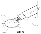
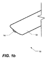
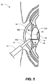
図1a及び図1bは、嚢切開装置10のいくつかの実施形態の平面図を示す。様々な特徴をより明確に示すために、図1a及び図1bのようないくつかの他の添付図面では縮尺比が同一ではなく且ついくつかの特徴が誇張されていることが当業者によって理解されるであろう。当業者は、示された構造が単なる例であり限定されるものではないことも理解するであろう。いくつかの実施形態では、嚢切開装置10は抵抗加熱要素12のほぼ円形の可撓ループ23を含むことができ、抵抗加熱要素12のほぼ円形の可撓ループ23は、眼32の水晶体前嚢509及び/又は水晶体後嚢513(例えば図5参照)上に局所的な加熱を生成すべく通電せしめられるので、ループ23内における嚢36の部分を剥離するために、貫通切断部(through cut)を生成し、又は弱くされた境界線を画成することができる。嚢切開装置10は、嚢切開又は切嚢を行うべく小切開創505を通して前房34内に定置されることができる。この処置は、例えば、白内障水晶体の水晶体超音波乳化吸引術と人工的な眼内レンズ(IOL)の挿入とを促進することができる。
For a more complete understanding of the present invention, reference is made to the following description, taken in conjunction with the accompanying drawings, in which:
Both the foregoing general description and the following detailed description are exemplary and merely exemplary and are intended to provide further explanation of the invention as claimed. Should be understood.
FIGS. 1 a and 1 b show plan views of several embodiments of the
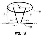
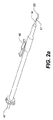
図1a〜図1dにおいて見られるように、様々な実施形態では、加熱要素12は、挿入スリーブ19の中心線27よりも上又は下にループ23の平面39をオフセットさせるように、オフセットさせる曲げを有する(例えば(本明細書においてワイヤ端部31として概して言及される)第1ワイヤ端部31a又は31c及び第2ワイヤ端部31b又は31dによって形成される)移行ネック部21を含むことができる。移行ネック部21を形成するワイヤ端部31は、中心線27から離れるように曲げられうる(例えば図1cにおいて示されるような距離29)。中心線27から離れるように曲げることによって、ループ23は前嚢面及び/又は後嚢面に対してより平行に設置されることができる。図5において示されるように、移行ネック部21におけるワイヤ端部31は、後嚢面35との一様な接触のためにループ23を定置すべく、嚢36の深さ33だけループ23をずらすことができる。嚢面に対して垂直な方向のおかげでワイヤ14の熱影響域が嚢上において小さいので、嚢の下部領域への二次的な熱損傷を防ぐための断熱が必要とされない。いくつかの実施形態では、ループ23の直径401(例えば図4参照)は、ループ23が前嚢切開又は(約4〜6mmの範囲内の直径を使用しうる前嚢切開よりも小さな(例えば約2〜4mmの範囲内の)直径401を使用しうる)後嚢切開において使用されるかに応じて調整されることができる。他の直径も考えられる。
As seen in FIGS. 1 a-1 d, in various embodiments, the heating element 12 has an offset bend that causes the
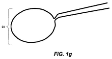
いくつかの実施形態では、移行ネック部21は約1〜2mmの長さ(絶縁部17からループ23までの距離)を有することができる(他の長さも考えられる)。いくつかの実施形態では、(例えば図1e及び図1fにおいて見られるような後嚢切開について)移行ネック部21はループ23の平面39に対してほぼ(例えば±20°)垂直である。他の角度も考えられる。例えば、移行ネック部21は、(例えば図1g及び図1hにおいて見られるような前嚢切開について)図1hにおいて見られるように平面の後部に対して測定された約135°又は45°である。他の角度も考えられる(例えば移行ネック部は平面の後部から約30°〜90°の範囲内であってもよい)。いくつかの実施形態では、ワイヤ端部31は、抵抗加熱要素12のワイヤ端部31間の隙間25の大きさを減少させるべく互いの方に向かって曲げられうる。隙間25は、隙間の端部間のショートを防ぐ(すなわち電流がループ23の回りを進む)のに十分な距離を維持するように最小化されうる。例えば、隙間25は約0.076±0.025mm(0.003±0.001インチ)の幅を有することができる。他の直径(例えば0.152mm(0.006インチ)又は別の例として0.051mm(0.002インチ)未満)も考えられる。隙間25は(電流がワイヤ14を通って進み且つ隙間25を横断しないように)ワイヤ端部31を互いから絶縁することができる。中心線27から離れるように曲げることによって、ワイヤ端部31が中心線27に対して平行である場合に可能であろう大きさよりも隙間25の大きさを更に減少させることができる。減少せしめられた隙間の大きさによって、剥離のためのより完全な円形の貫通切断部又は境界線がもたらされうる。(円形のループ23が示されるが、他の形状(例えば楕円形、長方形等)も考えられる。)減少せしめられた隙間の大きさのおかげで、隙間25の周りにおける嚢36とワイヤ14との接触が嚢36においてバイポーラジアテルミー(bipolar diathermy)を提供しうるので、加熱要素12における不連続性(すなわち隙間25)に拘わらずより完全な切嚢が促進される。平面39に対する、移行ネック部21の角度方向によって、完全な(又はほぼ完全な)切開部を有する、より円形なリングを形成すべく、隙間25における嚢36において真っ直ぐな縁が減少せしめられうる。隙間25の減少せしめられた幅のおかげで、隙間25の両側におけるワイヤ14からの隣接熱(neighboring heat)によって、隙間25の間の嚢26の部分が熱的に切断されうる。
In some embodiments, the
ワイヤ端部31は曲げられ且つ/又は真っ直ぐであってもよい(図1c及び図1d参照)。ワイヤ端部31についての他の形態も考えられる。「曲げ」の用語が終始使用されるが、ワイヤ端部31a及び31bは、他の方法(例えば型成形、押出成形等)を使用して形成され且つ/又は成形されてもよい。 The wire end 31 may be bent and / or straight (see FIGS. 1c and 1d). Other forms for the wire end 31 are also conceivable. Although the term “bending” is used throughout, the wire ends 31a and 31b may be formed and / or molded using other methods (eg, molding, extrusion, etc.).
様々な実施形態では、ループ23の形状は、ループ23が後嚢切開(例えば図1e及び図1f参照)又は前嚢切開(例えば図1g及び図1h参照)のいずれについて使用されるかに基づいて調整されうる。
In various embodiments, the shape of the
いくつかの実施形態によれば、抵抗加熱要素12は、超弾性ワイヤから作られた、少なくとも部分的に剥き出しの抵抗加熱要素を含むことができる。ワイヤ材料の超弾性と比較的高い電気抵抗率とを組み合わせることによって、圧潰可能なリング形状の加熱要素12が、局所加熱によって切嚢を行うように構築されることができる。加熱要素12は、圧潰可能なので、加熱要素12は角膜511における(例えば2mmの)小切開創505を通して眼32内に容易に挿入されうる。他の切開創の大きさ及び位置も考えられる。
According to some embodiments, the resistive heating element 12 can include an at least partially bare resistive heating element made from a superelastic wire. By combining the superelasticity of the wire material and a relatively high electrical resistivity, the collapsible ring-shaped heating element 12 can be constructed to cut through a local heating. Since the heating element 12 is collapsible, the heating element 12 can be easily inserted into the
嚢切開装置10は加熱要素12について極細の超弾性ワイヤ14を含むことができる。いくつかの実施形態では、ワイヤ14はニチノールのようなニッケルチタン合金から形成されることができ、ニチノールは超弾性特性及び形状記憶特性を示しうる。ワイヤ14は、超弾性(この用語は技術的に幾分より正確な用語「擬弾性(pseudoelastic)」についての同意語として本明細書では意図される)を有しうるので、荷重が適用されると、相当な量の変形に耐えることができ、且つ、荷重が取り除かれると、その元の形状に戻ることができる。(「形状記憶」とは、材料の変態温度よりも低い温度において変形される物体が変態温度よりも高い温度に温められるとその前の形状に戻る、いくつかの材料によって示される特性を指し、超弾性が「形状記憶」に関連するが形状記憶とは異なることが当業者によって理解されるであろう。ニチノールは両方の特性を示し、超弾性は変態温度よりも高い温度において示される。)さらに、ニチノールは、抵抗であり、このため電流で加熱されることができ、図1a〜図1cにおいて示される抵抗加熱要素12を形成するのに有用である。当然のことながら、抵抗であり且つ超弾性を有する他の材料がいくつかの実施形態ではニチノールの代わりに使用されてもよいことが当業者によって理解されるであろう。
The
ワイヤ14は、超弾性特性を有するので、挿入中に圧潰されることが可能であり、且つ使用中に予め形成された形状に戻ることができる。いくつかの実施形態では、粘弾性物質が切嚢前に前房34を膨らませるのに使用されうる。粘弾性物質は、十分に低い熱拡散率を有することができるので、加熱要素12の周りで断熱材として働くことができ、このため、加熱要素12の周辺において高度に集中化された、熱的に影響された区画を形成することを促進する。この区画の集中によって、近くの組織への二次的な損傷が低減されうる。実際には、加熱要素と嚢との間に粘弾性材料の薄いフィルムが捕捉されることを回避できないことがあるが、流体フィルムの小さな厚み(例えば約10μm)のおかげで、それでもなお、嚢36上に画成された小さな範囲が加熱要素における温度上昇に十分早く反応するであろうから、二次的損傷は回避される。
Because the
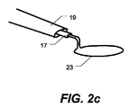
抵抗加熱要素12は、超弾性ワイヤ14から形成されたループ23を含むことができる。リード区域を形成すべくループ23から離れて延在するワイヤ14の端部は、可撓性を有する電気絶縁部17を用いて、電気的に隔てられた状態に保たれうる。いくつかの実施形態では、絶縁部17はリード区域の一部を囲むことができる。しかしながら、いくつかの実施形態では、ループ23から離れるように挿入スリーブ19内へ延在する二本のリードが、電流を抵抗加熱要素12のループに通すことができるように電気的に隔てられた状態に保たれうるならば、絶縁部17が、一方のリードのみを囲んでもよく、又はいずれか一方又は両方のリードを部分的にのみ囲んでもよいことが当業者によって理解されるであろう。絶縁部17は、生体適合性及び高い耐熱性を有する材料、例えばポリイミド又はテフロン(登録商標)を含むことができる。いくつかの実施形態では、絶縁部17は可撓性を有することができる。いくつかの実施形態では、一つ以上のクリンプチューブ(crimp tube)(例えば銀のクリンプチューブ)が、ループ23を受容するのに使用されうる(チューブは、ハンドピース内にループ23を繋止すべくループ23上に圧着されうる)。いくつかの実施形態では、絶縁部17は、互いから複数のチューブを電気的に絶縁すべくクリンプチューブの上に延在することができる。
The resistive heating element 12 can include a
いくつかの実施形態では、挿入スリーブ19は平らなチューブ又は円筒チューブを含むことができ、平らなチューブ又は円筒チューブは、絶縁部17を含むリード区域の一部と係合する。いくつかの実施形態では、挿入スリーブ19は絶縁部17と滑合部(slip-fit)を形成することができる。挿入スリーブ19は、嚢切開処置中に眼32内に加熱要素12を挿入し且つ後で加熱要素12を格納するのに使用されることができる。熱可塑性物質から作られうる挿入スリーブ19は、加熱要素12が加熱のための電源に選択的に接続されうるように、電気コネクタ及び/又は接続ワイヤも含むことができる。いくつかの実施形態では、挿入スリーブ19、絶縁材料17、及びワイヤ14は使い捨てユニットを形成することができ、使い捨てユニットは使用中にハンドピース又は他の器具に選択的に接続されることができ、ハンドピース又は他の器具は電流を供給することができる。いくつかの実施形態では、挿入スリーブ19はハンドピース41に連結されることができ(例えば図2a及び図2b参照)、ハンドピース41は外科用コンソール43(例えば図8参照)に連結されることができる。
In some embodiments, the
加熱要素12は、その超弾性特性のおかげで、眼32の前房34内への挿入のために圧潰されることができ、且つ前房34においてその予め画成された形状を取り戻すことができる。したがって、いくつかの実施形態では、挿入スリーブ19が含まれ又は使用されることができ、加熱要素12は挿入スリーブ19を通して押される。挿入スリーブ19内の格納位置における、圧潰された加熱要素12が図1b及び図2dにおいて示される。加熱要素12は挿入スリーブ19内への格納の際には圧潰可能であり且つ挿入スリーブ19からの取り出しの際にはその元の形状に展開可能でありうる。いくつかの実施形態では、挿入スリーブ19及び絶縁部17は単一の装置(又は別体の装置)内に取り込まれることができる。いくつかの実施形態では、別体のカートリッジが、(例えば挿入スリーブ19とは別に且つ/又は挿入スリーブ19の代わりに)カートリッジを通してループ23を圧潰し/展開するのに使用されてもよい。図2a及び図2bにおいて見られるように、ハンドピース41は格納レバー45を含むことができ、格納レバー45はスロット49に沿って摺動することができる。(挿入スリーブに取り付けられた)格納レバー45がスロット49の端部の方に向かって押されると、ループ23は挿入スリーブ19において包囲されうる(例えば図2d参照)。格納レバー45がスロット49に沿って引き戻されると、ループ23は挿入スリーブ19から抜け出すことができる(図2c参照)。ハンドピースの他の形態も考えられる。様々な実施形態では、ループ23は、処置の前及び/又は後に、挿入スリーブ19内に(例えば図1bにおいて見られるように)部分的に引っ込められ又は(例えば図2dにおいて見られるように)完全に引っ込められうる。いくつかの実施形態では、(図1bにおいて見られるように)部分的に露出されたワイヤは、挿入スリーブ19のようなガイドとして作用することができ、切開創内に挿入される。
The heating element 12 can be collapsed for insertion into the
図3a〜図3dは、一つの実施形態に係る、眼32内への加熱要素12の挿入を示す。処置の前に、加熱要素12のループ23が挿入スリーブ19内に引っ込められうるので、図3aにおいて見られるように、加熱要素12のループ23は挿入スリーブ19内にほぼ完全に包含される。このため、図3aにおいて示されるように、器具の先行先端部が小切開創505(図5参照)を通して眼32の前房34内に挿入されることができる。
3a-3d illustrate the insertion of the heating element 12 into the
図3bにおいて示されるように、挿入スリーブ19及び圧潰された加熱要素12は(後方の切嚢のために)水晶体嚢36の内部に(又は前方の切嚢のために水晶体前嚢の近くに)押されることができる。その後、加熱要素12のループ23は、図3cにおいて示されるように、その予め定められた形状を取り戻すことができ、次いで、嚢36に対して定置されることができる。移行ネック部は図3a〜図3dにおける嚢切開装置の上下の眺めからは知覚されることができない。その後、加熱要素12は例えば短パルスの電流又は一連のパルスの電流で通電せしめられうる。上述されたように、この加熱は、嚢36上に滑らかな連続的な切断部を生成すべく嚢36(例えば水晶体前嚢509及び/又は水晶体後嚢513)を焼き焦がすことができる。その後、加熱要素12は、図3dにおいて示されるように、挿入スリーブ19内に格納されることができ、次いで眼32から取り除かれることができる。嚢36の切断部は、鉗子のような従来の外科手術道具を使用して容易に取り除かれることができる。
As shown in FIG. 3b, the
超弾性ワイヤ14が可撓性を有するので、挿入スリーブ19は、加熱要素12が嚢36に対して設置されると、上向きに曲げられうる。ワイヤ14(及び、いくつかの場合、絶縁部17の変形特性が所与の装置10について定められうるので、加熱要素12の平面に対して形成された曲げ角度は、加熱要素12によって嚢36に適用される力の指標として使用されることができる。このため、許容可能な曲げ角度の範囲が、嚢36の最適な焼灼(cauterization)のための所望の適用力の範囲に対応するように、特定の装置10について定義されることができる。したがって、外科医が、図4において示されるように、予め定められた角度θに一致させ又はほぼ一致させるように曲げ角度を単純に操作することによって、加熱要素12と嚢36との間に所望の接触力を得ることができるのは便利である。いくつかの実施形態では、角度θは、ループ23の平面と、(ループ23の加熱要素12に対して真っ直ぐでありうる)絶縁部17との間の角度として定義されることができる。例えば、角度θはループ23とネック部21との間の移行部における曲げによって特徴付けられうる。
Because the
いくつかの実施形態では、加熱要素12の近くの組織へのあらゆる潜在的な二次的な損傷を更に低減すべく、断熱層が、嚢切開処置中に嚢36に対して配置されうる底面61が剥き出しのままであるように、抵抗加熱要素12によって形成されたループ23の少なくとも頂面59上に配置されることができる。斯かる一つの実施形態の断面図が図6aにおいて示され、図6aには断熱層55で部分的に囲まれた円形のワイヤ14の断面が示される。いくつかの実施形態では、超弾性ワイヤ14は、図6bにおいて示されるように、正方形又は長方形の断面を有してもよく、この場合、断熱材55はワイヤ14の三つの側部上に配置されうる。いずれかの場合も、断熱材55は、抵抗加熱要素12のループ23の全周又はループ23のほぼ全周においてワイヤ14上に配置されてもよい。
In some embodiments, a
上述された装置の形態を考慮すると、図7が、いくつかの実施形態に係る嚢切開装置を利用するための方法を示すことが当業者によって理解されるであろう。フローチャートにおいて提供された要素は、単なる例示である。提供された様々な要素は省かれることができ、追加の要素が加えられ、且つ/又は、様々な要素が、以下に提供された順序とは異なる順序で行われてもよい。 In view of the device configuration described above, it will be appreciated by those skilled in the art that FIG. 7 illustrates a method for utilizing a capsulotomy device according to some embodiments. The elements provided in the flowchart are merely examples. The various elements provided can be omitted, additional elements can be added, and / or the various elements can be performed in a different order than the order provided below.
701において、挿入スリーブ19が眼32内に定置されうる。加熱要素12は眼内への挿入の前に挿入スリーブ19内に格納されうる。例えば、加熱要素12は外科医によって且つ/又は装置10の製造中に格納されうる。図1bは、格納された加熱要素12の一つの実施形態を示す。いくつかの実施形態では、挿入スリーブ19を眼内に定置することは、挿入スリーブ19を挿入するために角膜511(又は眼32の他の部分)において小切開創505を作ることを含むことができる。
At 701, the
703において、加熱要素のループ23が(前嚢切開のために)眼32の前房34内に展開され又は(後嚢切開のために)水晶体嚢において展開されうる。本明細書において説明される加熱要素12が圧潰されうるので、挿入スリーブ19は、加熱要素のループ23の展開された直径401よりも小さい切開創505を通り抜けるような大きさにされうる。
At 703, the
705において、加熱要素12のループ23が、一旦眼32内に展開されると、水晶体前嚢509及び/又は水晶体後嚢513に対して定置されうる。いくつかの実施形態では、加熱要素12と嚢36との間に適用される力は、加熱要素12のリード区域における曲げを算定することによって計測されうる。
At 705, once the
707において、挿入スリーブ19と、加熱要素12によって形成された平面との間の角度が、正確な力が適用されたかどうか判断すべく、予め定められた角度(例えば図4参照)に適合されうる。
At 707, the angle between the
709において、加熱要素12が、嚢36に対して定置された後、電流の印加によって通電されうるので、ループ23が、加熱されて、水晶体前嚢509及び/又は水晶体後嚢513におけるほぼ円形の連続的な切断で水晶体嚢36を「焼く」ことができる。
At 709, since the heating element 12 can be placed against the
711において、嚢36を焼くことが完了した時点で、加熱要素12が挿入スリーブ19内に格納されることができ、713において、挿入スリーブ19が眼32から取り除かれうる。いくつかの実施形態では、嚢の剥離部は、鉗子のような外科手術道具を使用して取り除かれてもよい。
At 711, when baking of the
簡単に上述されたように、抵抗加熱要素12を通電することが短パルス(例えば20ms)の電流又は一連のパルス(例えば各1ms)を含むことは有利である。いくつかの実施形態では、パルス化された無線周波電源(pulsed radio-frequency power)が、嚢における二次的な熱損傷を低減し且つ隙間25における電気化学的反応を回避するのに使用されることができる。無線周波電源の周波数、波形、電圧、パルス幅、及び作用時間は、二次的な損傷を低減しつつ嚢36において連続的な貫通切断部を実現するように構成されうる。取り除かれるべき部分を囲んでいる嚢36の部分への二次的損傷を最小化しつつ、嚢36における連続的且つ円形(又は卵形)の貫通切断部が実現されうるように、特定の加熱要素構成について、電源の設定値(例えば、電圧、電流、パルス幅、パルスの数等)が制定されうることが当業者によって理解されるであろう。本明細書において説明される実施形態に係る特定の加熱要素12について電源の設定値を決定するとき、当業者は、複合的な作用メカニズムが嚢36の「切断」に寄与しうると考えることができる。例えば、加熱要素12の急速な加熱によってもたらされる、粘弾性材料及び組織液における蒸気「爆発」が、嚢材料の熱的破壊に加えて、嚢36の貫通切断に寄与しうる。
As briefly mentioned above, it is advantageous that energizing the resistive heating element 12 includes a short pulse (eg, 20 ms) of current or a series of pulses (eg, 1 ms each). In some embodiments, a pulsed radio-frequency power is used to reduce secondary thermal damage in the sac and avoid electrochemical reactions in the
図9は、切嚢修復装置の一つの実施形態を示す。いくつかの実施形態では、より小さな(本明細書では「切嚢修復装置901」として言及される)嚢切開装置10が切嚢(例えば連続環状嚢切開(CCC))を修復するのに使用されてもよい。切嚢の間、破れ目又は裂け目が、切嚢の周囲1041の縁に沿って生じ且つ後嚢内に延在しうる。これら径方向の裂け目は、更なる白内障の除去及び安全な眼内レンズの設置について、水晶体を不安定にすることがある。切嚢修復装置901の抵抗加熱要素のループ23は長円形状を有し且つ水晶体嚢の長さ及び幅よりも小さな長さ及び幅を有することができる。いくつかの実施形態では、長さ及び幅の両方が約10mmよりも小さい(例えば約4〜5mmの範囲内の長さ及び約2〜3mmの範囲内の幅)。他の長さ及び幅も可能である。いくつかの実施形態では、切嚢修復装置901のループ23は切嚢の周囲1041よりも小さな長さ及び幅を有してもよい(例えば、図3a〜図3dにおいて見られるように、切嚢の周囲1041は、水晶体嚢におけるその後の眼内レンズの設置のために水晶体嚢を取り除くように形成されうる)。長円形状/楕円形状が図9〜図11bにおいて示されるが、他の形状が使用されてもよい。例えば、異なる形状のワイヤが、異なる裂け目形状のために使用されてもよい。ワイヤ形状は例えば円形及び放物形を含むことができる。異なる大きさのループと、異なる幅に対する長さの比率とが、異なる裂け目の大きさに適応すべく使用されてもよい。
FIG. 9 shows one embodiment of a capsular repair device. In some embodiments, a smaller capsulotomy device 10 (referred to herein as “
いくつかの実施形態では、切嚢修復装置901は、上述された嚢切開装置10と実質的に同様である構造を有することができる(しかし、いくつかの実施形態では、嚢切開装置10よりも小さな寸法を有してもよい)。例えば、切嚢修復装置901のループ23は、移行ネック部21(例えば図1a参照)を備えた加熱要素を含むことができ、移行ネック部21は、挿入スリーブ19の中心線27よりも上又は下にループ23の平面39をオフセットさせるように、オフセットさせる曲げを有する(移行ネック部21を形成するワイヤ端部31は中心線27から離れるように曲がることができる)。いくつかの実施形態では、切嚢修復装置901は移行ネック部を含まなくてもよい(例えば切嚢修復装置901は真っ直ぐなネック部を含んでもよい)。いくつかの実施形態では、切嚢修復装置901は、ループ23の各端部の周りに別体のクリンプチューブを使用することができ、各端部は挿入スリーブ19内において互いから絶縁される。いくつかの実施形態では、挿入スリーブ19は使用されなくてもよい。例えば、ループ23は小径を有することができ、この小径によって、ループ23を挿入スリーブ19内に格納することなく眼内に挿入することができる。
In some embodiments, the
図10a及び図10bは、切嚢修復装置を使用する、小さな裂け目の修復の一つの実施形態を示す。上記されたように、ループ23は、眼内に挿入される前に挿入スリーブ19内に格納されてもよい。切嚢修復装置901のループ23は、一旦眼内に位置すると、スリーブ19の外側に延ばされ、ここではその元の形状に展開することができる。図10aにおいて見られるように、ループ23は、側部の小さな裂け目1051(例えば長さが約0〜1mmの裂け目)に重なるように整列されうる。裂け目の他の大きさも可能である。切嚢修復装置901は、主要な嚢切開装置(例えば水晶体嚢の主要な部分を取り除くのに使用される嚢切開装置10又は別の嚢切開装置)を挿入するのに使用される眼内の同じ穴を通して挿入されうる。いくつかの実施形態では、ループ23は、切嚢の周囲1041において、徐々に湾曲する外形を生成すべく、切嚢修復装置901のより広い領域を有する裂け目1051に僅かに重なるように裂け目1051に整列されてもよい。この態様では、修復湾曲部1055の入口点1053a及び出口点1053bは、(それ自体裂け目をもたらしうる応力集中を低減すべく)小さな/湾曲した外形を有することができる。
Figures 10a and 10b show one embodiment of a small tear repair using a scab repair device. As described above, the
図11a及び図11bは、切嚢修復装置を使用する大きな裂け目の修復の一つの実施形態を示す。図11aは、水晶体嚢内に延在した裂け目1151(例えば長さが約1mm〜2mmの裂け目)の上に整列された切嚢修復装置901のループ23を示す。他の裂け目の長さも可能である。修復湾曲部1155が切嚢の周囲1041と共にほぼ連続的な湾曲外形を形成することができる。切嚢修復装置901の加熱要素の長円形ループ903の狭い領域が、修復中に取り除かれる包囲材料の量を減少すべく、延在された裂け目115について使用されてもよい。上記されたように、いくつかの実施形態では、異なるループ形状が、異なる裂け目の大きさについて使用されてもよい(例えば、より突飛な(eccentric)楕円形状のワイヤが、延在した裂け目について使用されてもよい)。
FIGS. 11a and 11b show one embodiment of repairing a large tear using a capsular repair device. FIG. 11a shows the
図12は、切嚢修復のための方法の一つの実施形態のフローチャートを示す。フローチャートにおいて提供された要素は、単なる例示である。提供された様々な要素は省かれることができ、追加の要素が加えられ、且つ/又は、様々な要素が、以下に提供された順序とは異なる順序で行われてもよい。 FIG. 12 shows a flowchart of one embodiment of a method for incision repair. The elements provided in the flowchart are merely examples. The various elements provided can be omitted, additional elements can be added, and / or the various elements can be performed in a different order than the order provided below.
1201において、(例えば図7において説明された方法に従って)嚢切開が行われうる。嚢切開を行う他の方法(例えば外科用ナイフを使用すること)も考えられる。切嚢は後方の切嚢又は前方の切嚢を含むことができる。嚢切開の間、裂け目1051/1151が切嚢の周囲1041において形成されうる。
At 1201, a capsulotomy can be performed (eg, according to the method described in FIG. 7). Other methods of performing a capsulotomy (eg, using a surgical knife) are also contemplated. The incision can include a posterior or anterior sac. During a capsulotomy, a
1203において、切嚢修復装置901が、元の嚢切開装置10を挿入するのに使用される穴に挿入されうる。いくつかの実施形態では、切嚢修復装置901は、異なる穴(例えば切嚢修復のために形成された新しい穴)に挿入されてもよい。切嚢修復装置901のループ23は、挿入の間、挿入スリーブ19内に格納されてもよい。
At 1203, the
1205において、切嚢修復装置901のループ23が水晶体嚢内にスリーブ19から押し出されてその元の形状に展開することができる(上記されたように、ループ23は超弾性ニチノールワイヤ又は他のいくつかの形状記憶材料から形成されうる)。いくつかの実施形態では、ループ23は挿入スリーブ19から押し出され、又は挿入スリーブ19は、ループ23を露出すべく(例えば図2a及び図2bにおいて見られるようなレバー45を使用して)引き戻されてもよい。他の延在方法(例えばバネ又ソレノイドを使用すること)も可能である。
At 1205, the
1207において、ループ23が、裂け目1051/1151に重なるように切嚢の周囲1041上に設置されうる。
At 1207, the
1209において、電流がループ23に印加され、ループ23が、切嚢の周囲1041と共にほぼ連続的な湾曲外形を形成すべく下部の水晶体嚢材料を通して焼くことができる(例えば図10b及び11b参照)。
At 1209, a current is applied to the
1211において、ループ23がスリーブ19内に格納され、切嚢修復装置901が眼から引き出されうる。いくつかの実施形態では、ループ23が挿入スリーブ19内に引き込まれ又は挿入スリーブ19が(例えば図2a及び図2bにおいて見られるようなレバー45を使用して)ループ23の上に押されてもよい。他の格納方法(例えばバネ又はソレノイドを使用すること)も可能である。
At 1211, the
いくつかの実施形態では、(切嚢修復装置901を含む)嚢切開装置10及び/又は嚢切開装置10のための管理システム(例えばハンドピース41及び/又はコンソール43)は一つ以上のプロセッサ(例えばプロセッサ1001)及び/又はメモリ1003を含むことができる(例えば図8参照)。プロセッサ1001は単一の演算処理装置又は複数の演算処理装置を含むことができる。斯かる演算処理装置は、マイクロプロセッサ、コントローラ(マイクロコントローラであってもよい)、デジタル・シグナル・プロセッサ、マイクロコンピュータ、中央演算処理ユニット、フィールド・プログラマブル・ゲート・アレイ、プログラマブル・ロジック・デバイス、ステートマシン、論理回路、制御回路、アナログ回路、デジタル回路、及び/又は操作指令に基づいて(アナログ及び/又はデジタル)信号を処理する任意の装置である。プロセッサ1001に連結され且つ/又は組み込まれたメモリ1003は単一のメモリ装置又は複数のメモリ装置である。斯かるメモリ装置は、ROM、RAM、揮発性メモリ、不揮発性メモリ、スタティックメモリ、ダイナミックメモリ、フラッシュメモリ、キャッシュメモリ、及び/又はデジタル情報を記憶する任意の装置である。プロセッサ1001が、ステートマシン、アナログ回路、デジタル回路、及び/又はロジック回路を介してその一つ以上の機能を実施するとき、対応する操作指令を記憶するメモリ1003が、ステートマシン、アナログ回路、デジタル回路、及び/又はロジック回路を含む回路内に又は回路の外部に組み込まれうることに留意されたい。図に関連して示され且つ説明された要素の少なくともいくつかに対応する操作指令を、メモリ1003が記憶し且つプロセッサ1001が実行することができる。
In some embodiments, the capsulotomy device 10 (including the capsulotomy device 901) and / or the management system for the capsulotomy device 10 (eg, the
与えられた実施形態に対して様々な修正が当業者によってなされうる。例えば、いくつかの実施形態が、嚢切開装置10と関連して上述されたが、他の熱的な外科装置を用いて使用されることもできる。本明細書を考慮し且つ本明細書において開示された本発明を実施することによって、本発明の他の実施形態が当業者にとって明らかであるだろう。本明細書及び例が単なる例示としてみなされ、本発明の真の範囲及び思想が以下の特許請求の範囲及びその均等物によって示されることが意図されている。
Various modifications can be made to the given embodiments by those skilled in the art. For example, although some embodiments have been described above in connection with the
Claims (7)
前記超弾性ワイヤの第1端部と第2端部とを隔てる電気絶縁材料を具備する絶縁部であって、前記第1端部及び第2端部が、前記ループと当該絶縁部との間に移行ネック部を形成すべく、互いに近接し、且つ、少なくとも部分的に、前記ループによって画成された平面から当該絶縁部へ所定の角度で延在する、絶縁部と
を具備する、切嚢修復装置であって、
前記抵抗加熱要素が、嚢切開の周囲の修復のために該嚢切開の周囲における裂け目に重なるべく構成されるように、修復されるべき前記嚢切開の周囲の長さ及び幅よりも小さい長さ及び幅を有し、
前記絶縁部の周りに収まり、且つ前記抵抗加熱要素が格納位置にあるときに実質的に該抵抗加熱要素を包含するように構成された挿入スリーブを更に具備し、
前記絶縁部における、前記移行ネック部の一方の側の前記第1端部と前記第2端部との間の隙間が、前記ループにおける、前記移行ネック部の反対側の前記第1端部と前記第2端部との間の隙間よりも広い、
切嚢修復装置。 A resistance heating element comprising a superelastic wire of electrical resistance, the superelastic wire having a first end and a second end, and between the first end and the second end A resistance heating element that forms a loop with a gap in the
An insulating part comprising an electrically insulating material that separates a first end and a second end of the superelastic wire, wherein the first end and the second end are between the loop and the insulating part. An insulative sac comprising an insulative portion adjacent to each other and at least partially extending from the plane defined by the loop to the insulative portion at a predetermined angle to form a transition neck portion A repair device,
A length less than the perimeter and width of the capsulotomy to be repaired, such that the resistive heating element is configured to overlap a tear around the sactomy for repair around the capsulotomy And having a width,
And further comprising an insertion sleeve configured to fit around the insulation and substantially encompass the resistance heating element when the resistance heating element is in a retracted position;
The gap between the first end on one side of the transition neck and the second end in the insulating portion is the first end on the opposite side of the transition neck in the loop. Wider than the gap between the second end,
Incision repair device.
Applications Claiming Priority (5)
| Application Number | Priority Date | Filing Date | Title |
|---|---|---|---|
| US12/477,175 | 2009-06-03 | ||
| US12/477,175 US20100312252A1 (en) | 2009-06-03 | 2009-06-03 | Capsularhexis device with flexible heating element having an angled transitional neck |
| US12/754,119 | 2010-04-05 | ||
| US12/754,119 US8814854B2 (en) | 2009-06-03 | 2010-04-05 | Capsulotomy repair device and method for capsulotomy repair |
| PCT/US2010/033893 WO2010141179A1 (en) | 2009-06-03 | 2010-05-06 | Capsulotomy repair device and method for capsulotomy repair |
Publications (3)
| Publication Number | Publication Date |
|---|---|
| JP2012528675A JP2012528675A (en) | 2012-11-15 |
| JP2012528675A5 JP2012528675A5 (en) | 2013-06-06 |
| JP5711224B2 true JP5711224B2 (en) | 2015-04-30 |
Family
ID=42289569
Family Applications (1)
| Application Number | Title | Priority Date | Filing Date |
|---|---|---|---|
| JP2012513955A Active JP5711224B2 (en) | 2009-06-03 | 2010-05-06 | Incision repair device and incision repair method |
Country Status (8)
| Country | Link |
|---|---|
| US (1) | US8814854B2 (en) |
| EP (1) | EP2437699B1 (en) |
| JP (1) | JP5711224B2 (en) |
| CN (1) | CN102458320B (en) |
| AU (1) | AU2010257074B2 (en) |
| CA (1) | CA2761326C (en) |
| ES (1) | ES2654762T3 (en) |
| WO (1) | WO2010141179A1 (en) |
Families Citing this family (31)
| Publication number | Priority date | Publication date | Assignee | Title |
|---|---|---|---|---|
| US9125720B2 (en) | 2008-10-13 | 2015-09-08 | Alcon Research, Ltd. | Capsularhexis device with flexible heating element |
| US8137344B2 (en) | 2008-12-10 | 2012-03-20 | Alcon Research, Ltd. | Flexible, automated capsulorhexis device |
| US8157797B2 (en) | 2009-01-12 | 2012-04-17 | Alcon Research, Ltd. | Capsularhexis device with retractable bipolar electrodes |
| WO2010124233A2 (en) * | 2009-04-23 | 2010-10-28 | Rafael Medina | Instrument and method for creating controlled capsulorhexis for cataract surgery |
| US8814854B2 (en) | 2009-06-03 | 2014-08-26 | Alcon Research, Ltd. | Capsulotomy repair device and method for capsulotomy repair |
| US9241755B2 (en) | 2010-05-11 | 2016-01-26 | Alcon Research, Ltd. | Capsule polishing device and method for capsule polishing |
| US9149388B2 (en) | 2010-09-29 | 2015-10-06 | Alcon Research, Ltd. | Attenuated RF power for automated capsulorhexis |
| US20120158027A1 (en) * | 2010-12-16 | 2012-06-21 | Ala Moradian | Capsulotomy methods and apparatus using heat |
| US10206816B2 (en) * | 2011-10-21 | 2019-02-19 | Mynosys Cellular Devices, Inc. | Capsulotomy device |
| WO2013118855A1 (en) * | 2012-02-09 | 2013-08-15 | 塩野義製薬株式会社 | Heterocyclic ring and carbocyclic derivative |
| DE102012223076A1 (en) * | 2012-12-13 | 2014-07-03 | Geuder Ag | Instrument for stimulation or irritation and / or for abrasive treatment and / or for polishing a membrane or surface or inner surface in the human or animal eye |
| USD707818S1 (en) | 2013-03-05 | 2014-06-24 | Alcon Research Ltd. | Capsulorhexis handpiece |
| KR101484418B1 (en) * | 2013-12-16 | 2015-01-28 | 인제대학교 산학협력단 | Capsulorhexis apparatus |
| USD737438S1 (en) | 2014-03-04 | 2015-08-25 | Novartis Ag | Capsulorhexis handpiece |
| US9629747B2 (en) | 2014-09-17 | 2017-04-25 | Iantech, Inc. | Devices and methods for cutting lenticular tissue |
| RU2703694C2 (en) | 2014-09-17 | 2019-10-21 | Янтек, Инк. | Devices and methods for crystalline lens tissue removal |
| TW201722377A (en) | 2015-12-16 | 2017-07-01 | 諾華公司 | Devices and methods for a cannula-delivered treatment material application device |
| US10624785B2 (en) | 2016-01-30 | 2020-04-21 | Carl Zeiss Meditec Cataract Technology Inc. | Devices and methods for ocular surgery |
| CN109475431B (en) * | 2016-08-02 | 2021-04-23 | 爱尔康公司 | Enhancing performance of capsulotomy device |
| CN110114023B (en) * | 2016-10-26 | 2022-03-29 | 卡尔蔡司白内障医疗技术公司 | Method and apparatus for cutting a lens in an eye |
| KR101963758B1 (en) * | 2016-12-28 | 2019-03-29 | 부산대학교 산학협력단 | Electric Heating Tip and Thermal Cutting Device for Lens Anterior Capsule comprising the same |
| WO2018211507A1 (en) * | 2017-05-16 | 2018-11-22 | Valens Associated Inc. | Capsulotomy tool and system with blade heat-adjustment capability |
| BR112020011860A2 (en) | 2017-12-14 | 2020-11-24 | Carl Zeiss Meditec Cataract Technology Inc. | devices and methods for eye surgery |
| US11596547B2 (en) * | 2018-01-31 | 2023-03-07 | Centricity Vision, Inc. | Hydrodissection and posterior capsule opacification prevention during capsulotomy procedure |
| US10292862B1 (en) * | 2018-05-03 | 2019-05-21 | Richard Mackool | Ophthalmic surgical instruments and methods of use thereof |
| US10441462B1 (en) | 2018-05-03 | 2019-10-15 | Richard Mackool | Ophthalmic surgical instruments and methods of use thereof |
| US11166844B2 (en) | 2019-04-25 | 2021-11-09 | Alcon Inc. | Retinal patch graft and biopsy device |
| US11007079B1 (en) | 2019-12-02 | 2021-05-18 | Richard Mackool | Ophthalmic surgical instruments and snares thereof |
| US10485700B1 (en) | 2019-06-24 | 2019-11-26 | Richard Mackool | Ophthalmic surgical instruments and snares thereof |
| US10639195B1 (en) | 2019-08-19 | 2020-05-05 | Richard Mackool | Capsular retractors |
| RU2726596C1 (en) * | 2020-01-22 | 2020-07-14 | Федеральное государственное автономное учреждение "Межотраслевой научно-технический комплекс "Микрохирургия глаза" имени академика С.Н. Федорова" Министерства здравоохранения Российской Федерации | Method of performing anterior circular capsulorhexis |
Family Cites Families (266)
| Publication number | Priority date | Publication date | Assignee | Title |
|---|---|---|---|---|
| US560167A (en) | 1896-05-12 | holmes | ||
| US547867A (en) | 1895-10-15 | Island | ||
| US974879A (en) | 1910-01-29 | 1910-11-08 | George Edward Gwinn | Surgical instrument. |
| US3159161A (en) | 1962-11-14 | 1964-12-01 | Ness Richard Alton | Fistulizing canaliculus |
| US3539034A (en) | 1966-10-11 | 1970-11-10 | Carl H Tafeen | Paracervical block anesthesia assembly |
| US3844272A (en) | 1969-02-14 | 1974-10-29 | A Banko | Surgical instruments |
| US3915172A (en) | 1970-05-27 | 1975-10-28 | Ceskoslovenska Akademie Ved | Capillary drain for glaucoma |
| US3809093A (en) * | 1972-04-14 | 1974-05-07 | S Abraham | Surgical tool |
| US4002169A (en) * | 1972-04-18 | 1977-01-11 | Cupler Ii John A | Method and apparatus for performing surgery without tissue incision |
| SU452338A1 (en) | 1973-05-18 | 1974-12-05 | Предприятие П/Я А-3959 | Work tool for ultrasonic separation of biological tissue |
| US3949750A (en) * | 1974-10-07 | 1976-04-13 | Freeman Jerre M | Punctum plug and method for treating keratoconjunctivitis sicca (dry eye) and other ophthalmic aliments using same |
| US4026295A (en) * | 1975-06-19 | 1977-05-31 | Lieberman David M | Surgical knife |
| US4068664A (en) * | 1976-02-25 | 1978-01-17 | Texas Medical Products, Inc. | Surgical suction wand assembly and method |
| US4315509A (en) | 1977-01-10 | 1982-02-16 | Smit Julie A | Insertion and removal catheters and intestinal tubes for restricting absorption |
| US4368734A (en) * | 1978-01-27 | 1983-01-18 | Surgical Design Corp. | Surgical instrument |
| US4210146A (en) | 1978-06-01 | 1980-07-01 | Anton Banko | Surgical instrument with flexible blade |
| JPS592474B2 (en) * | 1979-12-19 | 1984-01-18 | 電気化学工業株式会社 | adhesive composition |
| US4301802A (en) | 1980-03-17 | 1981-11-24 | Stanley Poler | Cauterizing tool for ophthalmological surgery |
| DE3038024A1 (en) | 1980-10-08 | 1982-04-29 | Hans-Joachim Prof.Dr.med. 6650 Homburg Schlegel | Eye lens capsule opening instrument - has cutter head with annular guide track for axially-protruding blade |
| US4805616A (en) * | 1980-12-08 | 1989-02-21 | Pao David S C | Bipolar probes for ophthalmic surgery and methods of performing anterior capsulotomy |
| US4481948A (en) * | 1980-12-29 | 1984-11-13 | Sole Gary M | Medical instrument, and methods of constructing and utilizing same |
| US4367744A (en) * | 1980-12-29 | 1983-01-11 | Sole Gary M | Medical instrument, and method of utilizing same |
| NO147900C (en) | 1981-03-12 | 1983-07-06 | Finn Skjaerpe | MICROSURGICAL INSTRUMENT. |
| US4485816A (en) | 1981-06-25 | 1984-12-04 | Alchemia | Shape-memory surgical staple apparatus and method for use in surgical suturing |
| US4457757A (en) | 1981-07-20 | 1984-07-03 | Molteno Anthony C B | Device for draining aqueous humour |
| US4425908A (en) * | 1981-10-22 | 1984-01-17 | Beth Israel Hospital | Blood clot filter |
| SU1148613A1 (en) | 1981-12-30 | 1985-04-07 | Всесоюзный Научно-Исследовательский Институт Глазных Болезней | Apparatus for forming holes in anterior capsule of eye crystalline bursa |
| DE3205959A1 (en) | 1982-02-19 | 1983-09-01 | Hans Geuder GmbH, 6900 Heidelberg | Instrument for ophthalmic surgery to open and remove the anterior crystalline capsule |
| SU1050702A1 (en) | 1982-04-13 | 1983-10-30 | Горьковский государственный медицинский институт им.С.М.Кирова | Device for breaking and aspirating cataracta |
| DE3248101A1 (en) | 1982-12-24 | 1984-06-28 | Hans-Joachim Prof.Dr.med. 6650 Homburg Schlegel | Device for perforating the anterior wall of the crystalline capsule of the eye of a living being |
| US4530359A (en) | 1983-02-08 | 1985-07-23 | Helfgott Maxwell A | Ophthalmic perforating instrument and surgical method employing said instrument |
| US4530356A (en) | 1983-02-08 | 1985-07-23 | Helfgott Maxwell A | Ophthalmic surgical instrument with beveled tip |
| FR2544979B3 (en) | 1983-04-26 | 1987-05-22 | Moria Dugast Sa | SCISSOR FOR MICROSURGERY AND IN PARTICULAR OCULAR MICROSURGERY |
| US4665906A (en) | 1983-10-14 | 1987-05-19 | Raychem Corporation | Medical devices incorporating sim alloy elements |
| US4708138A (en) | 1983-10-27 | 1987-11-24 | Pazandak Bradford B | Rotating surgical cutting knife |
| JPS61501067A (en) | 1984-01-30 | 1986-05-29 | シユレ−ゲル・ハンス−ヨアキム | Living eye lens capsule anterior wall drilling device |
| SU1395314A1 (en) | 1984-02-24 | 1988-05-15 | Московский научно-исследовательский институт микрохирургии глаза | Arrangement for dissection of anterior crystalline |
| US4559942A (en) | 1984-02-29 | 1985-12-24 | William Eisenberg | Method utilizing a laser for eye surgery |
| US4570632A (en) * | 1984-03-16 | 1986-02-18 | Woods Randall L | Cystotome for eye surgery and method of opening lens capsule |
| DE3434930A1 (en) | 1984-09-22 | 1986-04-03 | Hans Geuder GmbH, 6900 Heidelberg | Ophthalmic surgical instrument (capsulotome) for perforation of the crystalline capsule of the eye |
| WO1986002257A1 (en) | 1984-10-19 | 1986-04-24 | Coopervision, Inc. | Surgical cutting instrument for ultrasonic eye surgery |
| US4955894A (en) | 1984-10-30 | 1990-09-11 | Alcon Laboratories, Inc. | Posterior capsulotomy knife |
| US4676243A (en) * | 1984-10-31 | 1987-06-30 | Aldebaran Xiii Consulting Company | Automated anterior capsulectomy instrument |
| US4616656A (en) | 1985-03-19 | 1986-10-14 | Nicholson James E | Self-actuating breast lesion probe and method of using |
| US4607622A (en) | 1985-04-11 | 1986-08-26 | Charles D. Fritch | Fiber optic ocular endoscope |
| US4706671A (en) | 1985-05-02 | 1987-11-17 | Weinrib Harry P | Catheter with coiled tip |
| SU1301400A1 (en) | 1985-09-10 | 1987-04-07 | О.И.Лебедев и Т.П.Шорников | Arrangement for ophthalmologic operations |
| FR2588751A1 (en) | 1985-10-17 | 1987-04-24 | Imbert Philippe | Trepan in particular for extracapsular extraction of a cataract |
| DE3672981D1 (en) | 1985-11-27 | 1990-08-30 | Thomas C White | TISSUE-IMPLANTABLE LIQUID DISTRIBUTION DEVICE. |
| US4781675A (en) | 1985-11-27 | 1988-11-01 | White Thomas C | Infusion cannula |
| US4729761A (en) * | 1985-11-27 | 1988-03-08 | White Thomas C | Tissue-implantable, fluid-dissipating device |
| US4766896A (en) | 1986-01-24 | 1988-08-30 | Pao David S C | Anterior capsulotomy procedures |
| US4885004A (en) | 1986-01-24 | 1989-12-05 | Pao David S C | Rotating stylus cystitome |
| SU1431752A1 (en) | 1986-07-24 | 1988-10-23 | М. Е. Манук н, Г. А. Арутюн н, Р. А. Бадал Н и Р. Н. Барсег н | Resector of crystalline capsule |
| SU1440496A1 (en) | 1986-09-15 | 1988-11-30 | Предприятие П/Я В-8534 | Apparatus for implanting intraocular lens into posterior chamber of the eye |
| US4869248A (en) | 1987-04-17 | 1989-09-26 | Narula Onkar S | Method and apparatus for localized thermal ablation |
| US4911161A (en) * | 1987-04-29 | 1990-03-27 | Noetix, Inc. | Capsulectomy cutting apparatus |
| US4766897A (en) | 1987-06-16 | 1988-08-30 | Heinz Smirmaul | Capsulectomy surgical instrument |
| US4900300A (en) * | 1987-07-06 | 1990-02-13 | Lee David A | Surgical instrument |
| DE8710541U1 (en) | 1987-07-31 | 1987-11-19 | Uthoff, Detlef, Dr., 2300 Kiel, De | |
| US6544254B1 (en) * | 1988-02-24 | 2003-04-08 | Patricia Era Bath | Combination ultrasound and laser method and apparatus for removing cataract lenses |
| AU3221589A (en) | 1988-03-31 | 1989-10-05 | Site Microsurgical Systems, Inc. | Means for tissue removal using an erbium host laser |
| US4936825A (en) * | 1988-04-11 | 1990-06-26 | Ungerleider Bruce A | Method for reducing intraocular pressure caused by glaucoma |
| IT1225673B (en) * | 1988-07-22 | 1990-11-22 | Luigi Bozzo | DESTRUCTOR DEVICE FOR USE IN THE URINARY OBSTRUCTIVE PATHOLOGY OF THE MALE AND INSTRUCTOR-EXTRACTOR INSTRUMENT OF THE DEVICE ITSELF |
| US4994066A (en) * | 1988-10-07 | 1991-02-19 | Voss Gene A | Prostatic stent |
| US4986825A (en) * | 1988-10-11 | 1991-01-22 | Concept, Inc. | Surgical cutting instrument |
| US4869716A (en) | 1988-10-24 | 1989-09-26 | Smirmaul Heinz J | Surgical instrument and method for cutting the lens of an eye |
| US4950272A (en) | 1989-06-19 | 1990-08-21 | Smirmaul Heinz J | Surgical instrument and method for removing the lens of an eye |
| US4955859A (en) | 1989-07-07 | 1990-09-11 | C. R. Bard, Inc. | High-friction prostatic stent |
| US6004330A (en) * | 1989-08-16 | 1999-12-21 | Medtronic, Inc. | Device or apparatus for manipulating matter |
| US5509923A (en) | 1989-08-16 | 1996-04-23 | Raychem Corporation | Device for dissecting, grasping, or cutting an object |
| US5904690A (en) * | 1989-08-16 | 1999-05-18 | Medtronic, Inc. | Device or apparatus for manipulating matter |
| US5632746A (en) | 1989-08-16 | 1997-05-27 | Medtronic, Inc. | Device or apparatus for manipulating matter |
| US5749879A (en) | 1989-08-16 | 1998-05-12 | Medtronic, Inc. | Device or apparatus for manipulating matter |
| US5047008A (en) | 1989-10-27 | 1991-09-10 | Storz Instrument Company | Vitrectomy probe |
| US5306237A (en) | 1989-11-06 | 1994-04-26 | Mectra Labs, Inc. | Disposable lavage |
| SU1766403A1 (en) | 1990-01-12 | 1992-10-07 | Межотраслевой научно-технический комплекс "Микрохирургия глаза" | Method for extracting traumatic cataract |
| US5180362A (en) * | 1990-04-03 | 1993-01-19 | Worst J G F | Gonio seton |
| DE4012882A1 (en) | 1990-04-23 | 1991-10-31 | Michael Dr Med Sasu | Surgical instrument for removing cataract from eye - has circular blade which is rotated by drive in handle |
| US5199445A (en) * | 1990-06-06 | 1993-04-06 | Look, Inc. | Stromal puncture method |
| US5188634A (en) * | 1990-07-13 | 1993-02-23 | Trimedyne, Inc. | Rotatable laser probe with beveled tip |
| US5911699A (en) * | 1990-07-17 | 1999-06-15 | Aziz Yehia Anis | Removal of tissue |
| GB9017784D0 (en) | 1990-08-14 | 1990-09-26 | Mahmud Ahmed S D | Disposable capsulotomy knife with suction for extra-capsular cataract extraction |
| US5203865A (en) * | 1990-08-23 | 1993-04-20 | Siepser Steven B | Surgical knives for use in ophthalmic surgery |
| JP3256540B2 (en) | 1990-10-09 | 2002-02-12 | メッドトロニック・インコーポレイテッド | Device or device for manipulating the target object |
| FR2707872A1 (en) | 1990-10-19 | 1995-01-27 | Defauchy Arlette | Novel opthalmological surgical method and adapted surgical instrument |
| US5346491A (en) | 1991-03-28 | 1994-09-13 | Sony Corporation | Feed device for bipolar electrodes for capsulotomy |
| RU1790935C (en) | 1991-04-11 | 1993-01-30 | Межотраслевой научно-технический комплекс "Микрохирургия глаза" | Exsector for anterior lens capsule |
| RU1790934C (en) | 1991-04-11 | 1993-01-30 | Межотраслевой научно-технический комплекс "Микрохирургия глаза" | Iridocapsuloretractor |
| US5364405A (en) | 1991-04-23 | 1994-11-15 | Allergan, Inc. | Ophthalmic instrument with curved suction conduit and internal ultrasound needle |
| US5242449A (en) | 1991-04-23 | 1993-09-07 | Allergan, Inc. | Ophthalmic instrument |
| FR2676355A1 (en) | 1991-05-14 | 1992-11-20 | De Crepy Bruno | Surgical prosthesis for vascular surgery |
| FR2677244A1 (en) | 1991-06-05 | 1992-12-11 | Kabbara Jamil | Apparatus for making an incision in the anterior wall of the crystalline capsule of the eye |
| US5123906A (en) * | 1991-06-20 | 1992-06-23 | Kelman Charles D | Surgical toroidal snare |
| US5312413A (en) | 1991-07-17 | 1994-05-17 | Eaton Alexander M | Instrumentation for ophthalmic surgery and method of using the same |
| US5234436A (en) | 1991-07-17 | 1993-08-10 | Eaton Alexander M | Sheath structure for a surgical knife |
| ES2103635B1 (en) | 1991-09-06 | 1998-05-01 | Espinos Guillermo Garau | MEDICAL AND SURGICAL APPARATUS TO SIMPLIFY THE PREVIOUS CAPSULOTOMY TECHNIQUE, IN THE CATARACT SURGERY. |
| IT1249714B (en) | 1991-10-11 | 1995-03-09 | Mauro Caponi | DOUBLE CANNAL SURGICAL INSTRUMENT. |
| US5135530A (en) | 1991-11-12 | 1992-08-04 | Lara Lehmer | Anterior capsular punch with deformable cutting member |
| US5269787A (en) | 1991-12-17 | 1993-12-14 | Cozean Jr Charles H | Apparatus and method for capsulorhexis |
| US5843019A (en) | 1992-01-07 | 1998-12-01 | Arthrocare Corporation | Shaped electrodes and methods for electrosurgical cutting and ablation |
| US5366443A (en) | 1992-01-07 | 1994-11-22 | Thapliyal And Eggers Partners | Method and apparatus for advancing catheters through occluded body lumens |
| US5360399A (en) | 1992-01-10 | 1994-11-01 | Robert Stegmann | Method and apparatus for maintaining the normal intraocular pressure |
| US5242404A (en) | 1992-02-12 | 1993-09-07 | American Cyanamid Company | Aspiration control system |
| EP0680282A1 (en) | 1992-04-16 | 1995-11-08 | MICHALOS, Peter | Surgical cutting instrument |
| US5522829A (en) | 1992-04-16 | 1996-06-04 | Arthur D. Little Enterprises, Inc. | Surgical cutting instrument |
| US5261923A (en) | 1992-04-23 | 1993-11-16 | Soares Christopher J | Method and apparatus for continuous circular capsulorehexis |
| US5322504A (en) * | 1992-05-07 | 1994-06-21 | United States Surgical Corporation | Method and apparatus for tissue excision and removal by fluid jet |
| US5413574A (en) * | 1992-09-04 | 1995-05-09 | Fugo; Richard J. | Method of radiosurgery of the eye |
| US5700243A (en) | 1992-10-30 | 1997-12-23 | Pdt Systems, Inc. | Balloon perfusion catheter |
| US5342377A (en) | 1992-12-18 | 1994-08-30 | Lazerson Howard E | Rotating blade capsulotomy instrument and method of performing a capsulotomy |
| GB9303985D0 (en) | 1993-02-26 | 1993-04-14 | Bartholomew Richard S | Surgical cutting tool |
| US5423330A (en) * | 1993-03-10 | 1995-06-13 | The University Of Miami | Capsule suction punch instrument and method of use |
| FR2702955B1 (en) | 1993-03-26 | 1995-04-28 | Hagege Joseph | Instrument for eye surgery. |
| FI96733C (en) * | 1993-06-18 | 1996-08-12 | Nokia Telecommunications Oy | Subscriber network arrangement for connecting subscribers to the public telephone network |
| US5411510A (en) * | 1993-07-06 | 1995-05-02 | Fugo; Richard J. | Surgical blade and method for ocular surgery |
| CA2127637C (en) | 1993-07-26 | 2006-01-03 | Scott Bair | Fluid jet surgical cutting tool |
| DE9311879U1 (en) | 1993-08-03 | 1993-10-14 | Kuehl Wolfram Dr | Standardized capsulorhexis loop (NKS) for eye surgery |
| US5562619A (en) * | 1993-08-19 | 1996-10-08 | Boston Scientific Corporation | Deflectable catheter |
| US5455637A (en) | 1993-09-10 | 1995-10-03 | Comdisco, Inc. | Electrochromic eyewear system, rechargeable eyewear and external charger therefor |
| FR2710269A1 (en) | 1993-09-22 | 1995-03-31 | Voir Vivre | Implantable device for the treatment of edemas. |
| US5478338A (en) | 1993-09-24 | 1995-12-26 | Reynard; Michael | Fiber optic sleeve for surgical instruments |
| US5439474A (en) | 1993-10-08 | 1995-08-08 | Li Medical Technologies, Inc. | Morcellator system |
| US5445637A (en) * | 1993-12-06 | 1995-08-29 | American Cyanamid Company | Method and apparatus for preventing posterior capsular opacification |
| US5445636A (en) | 1993-12-06 | 1995-08-29 | American Cyanamid Company | Method and apparatus for preventing posterior capsular opacification |
| US5484433A (en) * | 1993-12-30 | 1996-01-16 | The Spectranetics Corporation | Tissue ablating device having a deflectable ablation area and method of using same |
| US5466234A (en) | 1994-01-31 | 1995-11-14 | Trimedyne, Inc. | Expandable laser catheter |
| KR970701021A (en) * | 1994-02-09 | 1997-03-17 | 에이. 실베스트리니 토마스 | AN ELECTROSURGICAL PROCEDURE RECURVING THE CORNEA |
| DE4407949B4 (en) * | 1994-03-09 | 2006-12-07 | Klaas, Dieter, Dr.med. | Probe for aspirating eye tissue |
| US5423841A (en) * | 1994-03-15 | 1995-06-13 | Kornefeld; Michael S. | Intraocular knife |
| AU681247B2 (en) * | 1994-04-15 | 1997-08-21 | Smith & Nephew, Inc. | Curved surgical instrument with segmented inner member |
| US5487725A (en) * | 1994-05-12 | 1996-01-30 | Syntec, Inc. | Pneumatic vitrectomy for retinal attachment |
| US5395361A (en) * | 1994-06-16 | 1995-03-07 | Pillco Limited Partnership | Expandable fiberoptic catheter and method of intraluminal laser transmission |
| US5569280A (en) | 1994-06-29 | 1996-10-29 | Kamerling; William H. | Ophthalmic template |
| US6616996B1 (en) | 1994-10-28 | 2003-09-09 | Medsource Trenton, Inc. | Variable stiffness microtubing and method of manufacture |
| US5527332A (en) * | 1994-11-02 | 1996-06-18 | Mectra Labs, Inc. | Tissue cutter for surgery |
| US5601094A (en) * | 1994-11-22 | 1997-02-11 | Reiss; George R. | Ophthalmic shunt |
| US5569197A (en) | 1994-12-21 | 1996-10-29 | Schneider (Usa) Inc | Drug delivery guidewire |
| US5891084A (en) * | 1994-12-27 | 1999-04-06 | Lee; Vincent W. | Multiple chamber catheter delivery system |
| DE19508805C2 (en) * | 1995-03-06 | 2000-03-30 | Lutz Freitag | Stent for placement in a body tube with a flexible support structure made of at least two wires with different shape memory functions |
| US5626558A (en) * | 1995-05-05 | 1997-05-06 | Suson; John | Adjustable flow rate glaucoma shunt and method of using same |
| IL113723A (en) * | 1995-05-14 | 2002-11-10 | Optonol Ltd | Intraocular implant |
| US5630827A (en) * | 1995-06-19 | 1997-05-20 | Dutch Ophthalmic Research Center International Bv | Vitreous removing apparatus |
| US5651783A (en) | 1995-12-20 | 1997-07-29 | Reynard; Michael | Fiber optic sleeve for surgical instruments |
| US5669923A (en) | 1996-01-24 | 1997-09-23 | Gordon; Mark G. | Anterior capsulotomy device and procedure |
| US5873883A (en) * | 1996-01-25 | 1999-02-23 | Cozean, Jr.; Charles H. | Hydraulic capsulorhexitome |
| JPH09215753A (en) * | 1996-02-08 | 1997-08-19 | Schneider Usa Inc | Self-expanding stent made of titanium alloy |
| WO1997030669A1 (en) | 1996-02-22 | 1997-08-28 | Svrcek Petr | Electrical tool for erosion of the structure of the human intraocular lens anterior capsula |
| AU1078997A (en) | 1996-04-12 | 1997-11-07 | Surgical Dynamics, Inc. | Surgical cutting device removably connected to a rotary drive element |
| US5989262A (en) * | 1996-04-15 | 1999-11-23 | Josephberg; Robert Gary | Sutureless pars plana vitrectomy tool |
| US5716363A (en) * | 1996-04-15 | 1998-02-10 | Josephberg; Robert Gary | Pars plana vitrectomy tool |
| US5670161A (en) | 1996-05-28 | 1997-09-23 | Healy; Kevin E. | Biodegradable stent |
| JPH1033549A (en) * | 1996-07-24 | 1998-02-10 | Shinji Kokubu | Laser probe |
| US5860994A (en) * | 1996-07-30 | 1999-01-19 | Yaacobi; Yoseph | Remotely operable intraocular surgical instrument for automated capsulectomies |
| US5857995A (en) | 1996-08-15 | 1999-01-12 | Surgical Dynamics, Inc. | Multiple bladed surgical cutting device removably connected to a rotary drive element |
| US5733276A (en) | 1996-08-20 | 1998-03-31 | Ramot University Authority For Applied Research & Industrial Development Ltd. | Method for prophylactic therapy for post-operative posterior capsular opacification |
| US5733297A (en) * | 1996-09-10 | 1998-03-31 | Medical Instrument Development Laboratories, Inc. | Cutter for surgical probe |
| US5957921A (en) | 1996-11-07 | 1999-09-28 | Optex Ophthalmologics, Inc. | Devices and methods useable for forming small openings in the lens capsules of mammalian eyes |
| US5827321A (en) | 1997-02-07 | 1998-10-27 | Cornerstone Devices, Inc. | Non-Foreshortening intraluminal prosthesis |
| US5728117A (en) * | 1997-03-11 | 1998-03-17 | Lash; Roger S. | Retractable capsulorrehexis instument |
| US5893862A (en) * | 1997-04-10 | 1999-04-13 | Pratt; Arthur William | Surgical apparatus |
| DE19719549C2 (en) | 1997-05-09 | 1999-10-14 | Joachim Schoen | Ophthalmic surgical instrument for opening the front lens capsule |
| US5921999A (en) | 1997-06-03 | 1999-07-13 | Dileo; Frank | System and method employing a pie-zoelectric crystal and transverse oscillation to perform a capsulotomy |
| US5911729A (en) * | 1997-08-13 | 1999-06-15 | United States Surgical Corporation | Electrocautery coring using solid needle |
| EP0898947A3 (en) | 1997-08-15 | 1999-09-08 | GRIESHABER & CO. AG SCHAFFHAUSEN | Method and apparatus to improve the outflow of the aqueous humor of an eye |
| DE19740530A1 (en) | 1997-09-15 | 1999-03-18 | Kreco Kreiner Consulting Ges F | Device for removing eye tissue, especially natural lens |
| US6217598B1 (en) * | 1997-11-25 | 2001-04-17 | Linvatec Corporation | End-cutting shaver blade |
| DE19809510A1 (en) | 1998-03-05 | 1999-09-23 | Till Anschuetz | Rhexis appliance for cutting front lens cap |
| US20010044625A1 (en) | 1998-05-27 | 2001-11-22 | Cary Hata | Catheter for circular tissue ablation and methods thereof |
| US6066138A (en) | 1998-05-27 | 2000-05-23 | Sheffer; Yehiel | Medical instrument and method of utilizing same for eye capsulotomy |
| US6036688A (en) * | 1998-06-17 | 2000-03-14 | Edwards; Stuart D. | Radio frequency refractive keratectomy apparatus and method |
| US6264668B1 (en) | 1998-09-16 | 2001-07-24 | Arnold S. Prywes | Ophthalmologic instrument for producing a fistula in the sclera |
| US6241721B1 (en) * | 1998-10-09 | 2001-06-05 | Colette Cozean | Laser surgical procedures for treatment of glaucoma |
| US6162202A (en) | 1998-10-26 | 2000-12-19 | Sicurelli; Robert | Flexible syringe needle |
| EP1010410A1 (en) | 1998-12-16 | 2000-06-21 | Optisoins SA | Surgical instrument for cutting the lens capsule |
| GR1003307B (en) | 1999-02-17 | 2000-01-25 | Surgical knife-capsulotome | |
| WO2000048520A1 (en) * | 1999-02-17 | 2000-08-24 | Bausch & Lomb Incorporated | Methods, apparatus and system for removal of lenses from mammalian eyes |
| US6135998A (en) | 1999-03-16 | 2000-10-24 | Board Of Trustees Of The Leland Stanford Junior University | Method and apparatus for pulsed plasma-mediated electrosurgery in liquid media |
| US6440103B1 (en) | 1999-03-17 | 2002-08-27 | Surgijet, Inc. | Method and apparatus for thermal emulsification |
| US20020007150A1 (en) * | 1999-04-09 | 2002-01-17 | Stephen H. Johnson | Instrument sheath and blade guide |
| US6165190A (en) | 1999-06-01 | 2000-12-26 | Nguyen; Nhan | Capsulectomy device and method therefore |
| US6306155B1 (en) | 1999-10-25 | 2001-10-23 | Becton, Dickinson And Company | Capsulorhexis forceps and method of use |
| AU776599B2 (en) | 1999-11-24 | 2004-09-16 | Grieshaber & Co. Ag | Device for improving the aqueous humour outflow in the eye of a living thing |
| US6440125B1 (en) * | 2000-01-04 | 2002-08-27 | Peter Rentrop | Excimer laser catheter |
| IL134370A0 (en) | 2000-02-03 | 2001-04-30 | Cutmed Ltd | A medical instrument for use in cataract surgery and a method for use thereof |
| US6379370B1 (en) | 2000-02-18 | 2002-04-30 | Matthew Feinsod | Incising apparatus for use in cataract surgery |
| JP2001252300A (en) | 2000-03-14 | 2001-09-18 | Mototsugu Nishinobu | Method for replacing crystalline lens substance |
| US6575929B2 (en) * | 2000-03-14 | 2003-06-10 | Alcon Manufacturing, Ltd. | Pumping chamber for a liquefaction handpiece |
| US6551326B1 (en) * | 2000-04-17 | 2003-04-22 | Anthony Y. Van Heugten | Capsulorrhexis device |
| US6503263B2 (en) * | 2000-09-24 | 2003-01-07 | Medtronic, Inc. | Surgical micro-shaving instrument with elevator tip |
| US20040116950A1 (en) * | 2000-11-28 | 2004-06-17 | The Regents Of The University Of Michigan | Instrument and method for creating an intraocular incision |
| US6629980B1 (en) | 2000-11-28 | 2003-10-07 | The Regents Of The University Of Michigan | Instrument and method for creating an intraocular incision |
| WO2002054941A2 (en) | 2001-01-11 | 2002-07-18 | Rita Medical Systems Inc | Bone-treatment instrument and method |
| WO2002056805A2 (en) * | 2001-01-18 | 2002-07-25 | The Regents Of The University Of California | Minimally invasive glaucoma surgical instrument and method |
| EP1977724A1 (en) | 2001-04-07 | 2008-10-08 | Glaukos Corporation | System for treating ocular disorders |
| US20020161365A1 (en) | 2001-04-25 | 2002-10-31 | Heraldo Martins | Method of incision/excision/coagulation of scleral, peri-scleral, iris and corneal tissues with a bipolar pulsed high frequency diathermy tip |
| DE10220253A1 (en) | 2001-05-04 | 2002-11-14 | Michael Ulrich Dardenne | Surgical instrument for removing circular tissue disks from the front and rear lens capsule of the eye has a fast rotating support for blade elements that allows disks to be removed without uncontrolled tearing of the tissue |
| US7331984B2 (en) * | 2001-08-28 | 2008-02-19 | Glaukos Corporation | Glaucoma stent for treating glaucoma and methods of use |
| WO2003022174A2 (en) | 2001-09-07 | 2003-03-20 | Siepser Steven B | Intraocular lens extracting device |
| CN2501478Y (en) | 2001-09-20 | 2002-07-24 | 李钟实 | Tweezers for eye surgery |
| FR2830186B1 (en) | 2001-10-03 | 2004-06-11 | Didier Ducournau | TOOL FOR THE INCISION OF SCLEROTICS FOR THE PLACEMENT OF A BREWING CANNULA AND CORRESPONDING BREWING CANNULA |
| US20030088253A1 (en) | 2001-11-07 | 2003-05-08 | Seil Randolph L | Dual action ophthalmic implant extractor |
| US8491549B2 (en) | 2001-11-21 | 2013-07-23 | Iscience Interventional Corporation | Ophthalmic microsurgical system |
| US7964214B2 (en) | 2006-07-13 | 2011-06-21 | Peyman Gholam A | Method and composition for hyperthermally treating cells in the eye with simultaneous imaging |
| US20030225420A1 (en) * | 2002-03-11 | 2003-12-04 | Wardle John L. | Surgical coils and methods of deploying |
| US6780178B2 (en) | 2002-05-03 | 2004-08-24 | The Board Of Trustees Of The Leland Stanford Junior University | Method and apparatus for plasma-mediated thermo-electrical ablation |
| US8043286B2 (en) | 2002-05-03 | 2011-10-25 | The Board Of Trustees Of The Leland Stanford Junior University | Method and apparatus for plasma-mediated thermo-electrical ablation |
| AUPS226402A0 (en) * | 2002-05-13 | 2002-06-13 | Advanced Metal Coatings Pty Limited | An ablation catheter |
| US20040106929A1 (en) * | 2002-08-20 | 2004-06-03 | Samuel Masket | Method and apparatus for performing an accurately sized and placed anterior capsulorhexis |
| EP1555973A1 (en) | 2002-11-01 | 2005-07-27 | Jörgen Holmen | Methods and devices usable in eye surgery |
| WO2004073524A1 (en) | 2003-02-20 | 2004-09-02 | Manoa Medical, Inc. | Bendable cutting device |
| WO2004093761A1 (en) * | 2003-04-16 | 2004-11-04 | Iscience Surgical Corporation | Opthalmic microsurgical instruments |
| FR2855745A1 (en) | 2003-06-03 | 2004-12-10 | Joseph Leon | Intraocular lens capsule part cutting device for cataract surgery, has ring with cutting edge, folded in guide tube during its insertion into eye and unfolded to be applied on capsule for repeatedly performing cutting operation |
| FR2855746A1 (en) | 2003-06-03 | 2004-12-10 | Joseph Leon | Intraocular lens capsule part cutting device for cataract surgery, has circular wire with cutting edge and rolled in guide tube during its insertion into eye and unrolled to be applied on capsule to repeatedly perform cutting operation |
| EP1633236B1 (en) | 2003-06-10 | 2013-04-10 | Neomedix Corporation | Device for treatment of glaucoma and other surgical procedures and method of producing such device |
| EP1631204B1 (en) | 2003-06-10 | 2012-04-04 | Neomedix Corporation | Tubular cutter device |
| ES2544478T3 (en) * | 2003-06-10 | 2015-08-31 | Neomedix Corporation | Electrosurgical device for selective tissue cutting |
| US7785337B2 (en) * | 2003-09-09 | 2010-08-31 | Medtronic Xomed, Inc. | Surgical micro-burring instrument and method of performing sinus surgery |
| US7585295B2 (en) | 2003-12-23 | 2009-09-08 | Itos International Ltd. | Thermal airflow tool and system |
| US20060259053A1 (en) | 2004-04-09 | 2006-11-16 | El-Mansoury Jeylan A | Automated ophthalmic device for performance of capsulorhexis |
| US20050228419A1 (en) | 2004-04-09 | 2005-10-13 | El-Mansoury Jeylan A | Automated ophthalmic device for performance of capsulorhexis |
| DE102004021754A1 (en) | 2004-04-30 | 2005-11-24 | Reinhardt Thyzel | Device for removing epithelial cells from a lens capsular bag of a human or animal eye |
| US20100145331A1 (en) | 2004-06-02 | 2010-06-10 | Chrisitian Steven C | Loop Ablation Apparatus and Method |
| US8262682B2 (en) * | 2004-08-10 | 2012-09-11 | Asico Llc | Nucleus chopper and splitter |
| US20060100617A1 (en) | 2004-11-09 | 2006-05-11 | Alcon, Inc. | Capsularhexis device |
| ES2390352T3 (en) * | 2005-04-13 | 2012-11-12 | Valens Associated Inc. | Thermal capsulotomy tool and system |
| US9675495B2 (en) | 2005-04-13 | 2017-06-13 | David Scott Michelson | Capsulotomy instrument |
| WO2006117772A1 (en) | 2005-05-02 | 2006-11-09 | Itos International Ltd. | Thermal burning ring tool and system |
| JP4834337B2 (en) | 2005-07-06 | 2011-12-14 | 千寿製薬株式会社 | Anterior lens capsule cutter |
| US20090054904A1 (en) * | 2005-07-18 | 2009-02-26 | Phaco Treat Ab | Methods and devices for eye surgery |
| EP1912574A4 (en) * | 2005-08-10 | 2010-08-04 | Insight Instr Inc | Tool for extracting vitreous samples from an eye |
| US20070049957A1 (en) * | 2005-08-29 | 2007-03-01 | Pedro Benitez | Ccutter |
| US8016843B2 (en) * | 2005-09-09 | 2011-09-13 | Alcon Research Ltd | Ultrasonic knife |
| US7763032B2 (en) | 2005-12-20 | 2010-07-27 | Ellis Forrest J | Method and apparatus for forming an aperture in a lens capsule of an eye |
| JP2009534129A (en) | 2006-04-18 | 2009-09-24 | カスケード オフタルミクス | Intraocular pressure attenuator |
| GB2437252A (en) | 2006-04-19 | 2007-10-24 | Daniel Calladine | Capsulorhexis custotomes and capsulorhexis forceps with visible scale at tips |
| WO2008080149A1 (en) | 2006-12-22 | 2008-07-03 | Mynosys Cellular Devices, Inc. | Microsurgery device for lens capsule surgery |
| US8323296B2 (en) | 2007-03-15 | 2012-12-04 | Boris Malyugin | Ring used in a small pupil phacoemulsification procedure |
| US7660782B2 (en) | 2007-10-05 | 2010-02-09 | Wipro Limited | Architecture for master data management in an enterprise |
| US8235978B2 (en) * | 2007-11-01 | 2012-08-07 | Valens Associated Inc. | Thermal capsulotomy tool and system |
| US20090137992A1 (en) * | 2007-11-27 | 2009-05-28 | Ravi Nallakrishnan | Apparatus and Method for Treating Glaucoma |
| FR2924924B1 (en) | 2007-12-17 | 2010-09-24 | Pascal Pietrini | DEVICE FOR ABLATION OF THE CAPSULAR CAPSULAR BOTTOM CAPSULE. |
| ES2542302T3 (en) | 2008-05-15 | 2015-08-04 | Mynosys Cellular Devices, Inc. | Ophthalmic surgical device for capsulotomy |
| US20090287143A1 (en) | 2008-05-15 | 2009-11-19 | Casey Line | Small Gauge Mechanical Tissue Cutter/Aspirator Probe For Glaucoma Surgery |
| US20090287233A1 (en) | 2008-05-15 | 2009-11-19 | Huculak John C | Small Gauge Mechanical Tissue Cutter/Aspirator Probe For Glaucoma Surgery |
| GB0811087D0 (en) | 2008-06-17 | 2008-07-23 | Nottingham University Hospital | Surgical cutting implement |
| KR101039394B1 (en) | 2008-08-05 | 2011-06-08 | 인하대학교 산학협력단 | Eye lens capsule incision apparatus |
| US9125720B2 (en) | 2008-10-13 | 2015-09-08 | Alcon Research, Ltd. | Capsularhexis device with flexible heating element |
| US8137344B2 (en) * | 2008-12-10 | 2012-03-20 | Alcon Research, Ltd. | Flexible, automated capsulorhexis device |
| US8157797B2 (en) * | 2009-01-12 | 2012-04-17 | Alcon Research, Ltd. | Capsularhexis device with retractable bipolar electrodes |
| WO2010124233A2 (en) | 2009-04-23 | 2010-10-28 | Rafael Medina | Instrument and method for creating controlled capsulorhexis for cataract surgery |
| US8814854B2 (en) | 2009-06-03 | 2014-08-26 | Alcon Research, Ltd. | Capsulotomy repair device and method for capsulotomy repair |
| US20100312252A1 (en) | 2009-06-03 | 2010-12-09 | Guangyao Jia | Capsularhexis device with flexible heating element having an angled transitional neck |
| US20110054384A1 (en) | 2009-08-26 | 2011-03-03 | Brown David C | Sonic Device for Use in Capsule of Eye |
| US8986302B2 (en) * | 2009-10-09 | 2015-03-24 | Ethicon Endo-Surgery, Inc. | Surgical generator for ultrasonic and electrosurgical devices |
| US20110202049A1 (en) | 2010-02-18 | 2011-08-18 | Alcon Research, Ltd. | Small Gauge Ablation Probe For Glaucoma Surgery |
| US9241755B2 (en) | 2010-05-11 | 2016-01-26 | Alcon Research, Ltd. | Capsule polishing device and method for capsule polishing |
| NO2575711T3 (en) | 2010-06-07 | 2018-01-06 | ||
| KR101039398B1 (en) | 2010-10-26 | 2011-06-08 | 인하대학교 산학협력단 | Eye lens capsule incision apparatus |
| US20120158027A1 (en) * | 2010-12-16 | 2012-06-21 | Ala Moradian | Capsulotomy methods and apparatus using heat |
| US8591577B2 (en) * | 2010-12-16 | 2013-11-26 | Bausch & Lomb Incorporated | Capsulotomy device and method using electromagnetic induction heating |
| US20130066351A1 (en) | 2011-03-08 | 2013-03-14 | Christopher Kenneth Giardina | Apparatus for creating an annular incision in soft tissue |
| US10285855B2 (en) | 2011-08-05 | 2019-05-14 | Mynosys Cellular Devices, Inc. | Capsulotomy device with suction cup compression chamber |
| US10206816B2 (en) | 2011-10-21 | 2019-02-19 | Mynosys Cellular Devices, Inc. | Capsulotomy device |
| US20150039008A1 (en) | 2011-11-15 | 2015-02-05 | Naoki Suzuki | Surgical instrument |
| US20130158573A1 (en) | 2011-12-16 | 2013-06-20 | Moria Sa | Ophthalmic surgery instrument |
-
2010
- 2010-04-05 US US12/754,119 patent/US8814854B2/en active Active
- 2010-05-06 AU AU2010257074A patent/AU2010257074B2/en active Active
- 2010-05-06 WO PCT/US2010/033893 patent/WO2010141179A1/en active Application Filing
- 2010-05-06 CA CA2761326A patent/CA2761326C/en active Active
- 2010-05-06 CN CN201080024265.5A patent/CN102458320B/en active Active
- 2010-05-06 ES ES10720215.2T patent/ES2654762T3/en active Active
- 2010-05-06 EP EP10720215.2A patent/EP2437699B1/en active Active
- 2010-05-06 JP JP2012513955A patent/JP5711224B2/en active Active
Also Published As
| Publication number | Publication date |
|---|---|
| EP2437699B1 (en) | 2017-11-22 |
| US20100312232A1 (en) | 2010-12-09 |
| CA2761326A1 (en) | 2010-12-09 |
| WO2010141179A1 (en) | 2010-12-09 |
| US8814854B2 (en) | 2014-08-26 |
| CA2761326C (en) | 2017-08-01 |
| ES2654762T3 (en) | 2018-02-15 |
| AU2010257074B2 (en) | 2015-05-14 |
| AU2010257074A1 (en) | 2011-12-08 |
| CN102458320B (en) | 2014-11-12 |
| EP2437699A1 (en) | 2012-04-11 |
| JP2012528675A (en) | 2012-11-15 |
| CN102458320A (en) | 2012-05-16 |
Similar Documents
| Publication | Publication Date | Title |
|---|---|---|
| JP5711224B2 (en) | Incision repair device and incision repair method | |
| JP5675791B2 (en) | A capsulotomy device with a flexible heating element having an angled transition neck | |
| US9125720B2 (en) | Capsularhexis device with flexible heating element | |
| US9241755B2 (en) | Capsule polishing device and method for capsule polishing | |
| EP3493777B1 (en) | Enhancing performance of a capsulotomy device |
Legal Events
| Date | Code | Title | Description |
|---|---|---|---|
| A521 | Request for written amendment filed |
Free format text: JAPANESE INTERMEDIATE CODE: A523 Effective date: 20130418 |
|
| A621 | Written request for application examination |
Free format text: JAPANESE INTERMEDIATE CODE: A621 Effective date: 20130418 |
|
| A977 | Report on retrieval |
Free format text: JAPANESE INTERMEDIATE CODE: A971007 Effective date: 20140124 |
|
| A131 | Notification of reasons for refusal |
Free format text: JAPANESE INTERMEDIATE CODE: A131 Effective date: 20140204 |
|
| A02 | Decision of refusal |
Free format text: JAPANESE INTERMEDIATE CODE: A02 Effective date: 20140805 |
|
| A521 | Request for written amendment filed |
Free format text: JAPANESE INTERMEDIATE CODE: A523 Effective date: 20140930 |
|
| A911 | Transfer to examiner for re-examination before appeal (zenchi) |
Free format text: JAPANESE INTERMEDIATE CODE: A911 Effective date: 20141105 |
|
| A131 | Notification of reasons for refusal |
Free format text: JAPANESE INTERMEDIATE CODE: A131 Effective date: 20141209 |
|
| A521 | Request for written amendment filed |
Free format text: JAPANESE INTERMEDIATE CODE: A523 Effective date: 20150108 |
|
| TRDD | Decision of grant or rejection written | ||
| A01 | Written decision to grant a patent or to grant a registration (utility model) |
Free format text: JAPANESE INTERMEDIATE CODE: A01 Effective date: 20150203 |
|
| A61 | First payment of annual fees (during grant procedure) |
Free format text: JAPANESE INTERMEDIATE CODE: A61 Effective date: 20150305 |
|
| R150 | Certificate of patent or registration of utility model |
Ref document number: 5711224 Country of ref document: JP Free format text: JAPANESE INTERMEDIATE CODE: R150 |
|
| R250 | Receipt of annual fees |
Free format text: JAPANESE INTERMEDIATE CODE: R250 |
|
| R250 | Receipt of annual fees |
Free format text: JAPANESE INTERMEDIATE CODE: R250 |
|
| S111 | Request for change of ownership or part of ownership |
Free format text: JAPANESE INTERMEDIATE CODE: R313111 Free format text: JAPANESE INTERMEDIATE CODE: R313113 |
|
| R350 | Written notification of registration of transfer |
Free format text: JAPANESE INTERMEDIATE CODE: R350 |
|
| R250 | Receipt of annual fees |
Free format text: JAPANESE INTERMEDIATE CODE: R250 |
|
| R250 | Receipt of annual fees |
Free format text: JAPANESE INTERMEDIATE CODE: R250 |
|
| R250 | Receipt of annual fees |
Free format text: JAPANESE INTERMEDIATE CODE: R250 |
|
| R250 | Receipt of annual fees |
Free format text: JAPANESE INTERMEDIATE CODE: R250 |
|
| R250 | Receipt of annual fees |
Free format text: JAPANESE INTERMEDIATE CODE: R250 |