JP5704975B2 - Image processing apparatus, image processing method, and program - Google Patents
Image processing apparatus, image processing method, and program Download PDFInfo
- Publication number
- JP5704975B2 JP5704975B2 JP2011050092A JP2011050092A JP5704975B2 JP 5704975 B2 JP5704975 B2 JP 5704975B2 JP 2011050092 A JP2011050092 A JP 2011050092A JP 2011050092 A JP2011050092 A JP 2011050092A JP 5704975 B2 JP5704975 B2 JP 5704975B2
- Authority
- JP
- Japan
- Prior art keywords
- color information
- color
- calculating
- information
- captured images
- Prior art date
- Legal status (The legal status is an assumption and is not a legal conclusion. Google has not performed a legal analysis and makes no representation as to the accuracy of the status listed.)
- Active
Links
Images


Classifications
-
- G—PHYSICS
- G06—COMPUTING; CALCULATING OR COUNTING
- G06T—IMAGE DATA PROCESSING OR GENERATION, IN GENERAL
- G06T15/00—3D [Three Dimensional] image rendering
- G06T15/50—Lighting effects
- G06T15/503—Blending, e.g. for anti-aliasing
-
- H—ELECTRICITY
- H04—ELECTRIC COMMUNICATION TECHNIQUE
- H04N—PICTORIAL COMMUNICATION, e.g. TELEVISION
- H04N13/00—Stereoscopic video systems; Multi-view video systems; Details thereof
- H04N13/10—Processing, recording or transmission of stereoscopic or multi-view image signals
- H04N13/106—Processing image signals
- H04N13/111—Transformation of image signals corresponding to virtual viewpoints, e.g. spatial image interpolation
-
- H—ELECTRICITY
- H04—ELECTRIC COMMUNICATION TECHNIQUE
- H04N—PICTORIAL COMMUNICATION, e.g. TELEVISION
- H04N13/00—Stereoscopic video systems; Multi-view video systems; Details thereof
- H04N13/10—Processing, recording or transmission of stereoscopic or multi-view image signals
- H04N13/106—Processing image signals
- H04N13/15—Processing image signals for colour aspects of image signals
-
- H—ELECTRICITY
- H04—ELECTRIC COMMUNICATION TECHNIQUE
- H04N—PICTORIAL COMMUNICATION, e.g. TELEVISION
- H04N13/00—Stereoscopic video systems; Multi-view video systems; Details thereof
- H04N13/20—Image signal generators
- H04N13/204—Image signal generators using stereoscopic image cameras
- H04N13/243—Image signal generators using stereoscopic image cameras using three or more 2D image sensors
-
- H—ELECTRICITY
- H04—ELECTRIC COMMUNICATION TECHNIQUE
- H04N—PICTORIAL COMMUNICATION, e.g. TELEVISION
- H04N13/00—Stereoscopic video systems; Multi-view video systems; Details thereof
- H04N13/20—Image signal generators
- H04N13/204—Image signal generators using stereoscopic image cameras
- H04N13/25—Image signal generators using stereoscopic image cameras using two or more image sensors with different characteristics other than in their location or field of view, e.g. having different resolutions or colour pickup characteristics; using image signals from one sensor to control the characteristics of another sensor
-
- H—ELECTRICITY
- H04—ELECTRIC COMMUNICATION TECHNIQUE
- H04N—PICTORIAL COMMUNICATION, e.g. TELEVISION
- H04N13/00—Stereoscopic video systems; Multi-view video systems; Details thereof
- H04N13/20—Image signal generators
- H04N13/257—Colour aspects
-
- G—PHYSICS
- G06—COMPUTING; CALCULATING OR COUNTING
- G06T—IMAGE DATA PROCESSING OR GENERATION, IN GENERAL
- G06T2200/00—Indexing scheme for image data processing or generation, in general
- G06T2200/21—Indexing scheme for image data processing or generation, in general involving computational photography
-
- H—ELECTRICITY
- H04—ELECTRIC COMMUNICATION TECHNIQUE
- H04N—PICTORIAL COMMUNICATION, e.g. TELEVISION
- H04N13/00—Stereoscopic video systems; Multi-view video systems; Details thereof
- H04N2013/0074—Stereoscopic image analysis
- H04N2013/0077—Colour aspects
-
- H—ELECTRICITY
- H04—ELECTRIC COMMUNICATION TECHNIQUE
- H04N—PICTORIAL COMMUNICATION, e.g. TELEVISION
- H04N13/00—Stereoscopic video systems; Multi-view video systems; Details thereof
- H04N2013/0074—Stereoscopic image analysis
- H04N2013/0081—Depth or disparity estimation from stereoscopic image signals
-
- H—ELECTRICITY
- H04—ELECTRIC COMMUNICATION TECHNIQUE
- H04N—PICTORIAL COMMUNICATION, e.g. TELEVISION
- H04N23/00—Cameras or camera modules comprising electronic image sensors; Control thereof
- H04N23/90—Arrangement of cameras or camera modules, e.g. multiple cameras in TV studios or sports stadiums
Description
本発明は複数のカメラを並べて撮影する多眼カメラに関する。 The present invention relates to a multi-lens camera for photographing a plurality of cameras side by side.
近年、デジタルカメラ等の撮像デバイスを複数配置した、所謂、多眼カメラアレイを用いた技術が開発されている。多眼カメラによる撮影により、被写体の3次元情報を取得し、任意の視点、視線方向の画像を生成したり、3次元画像表示のための視差画像を生成したりすることが可能である。あるいは、撮影後にフォーカス位置や、被写界深度を変更した画像を生成することも可能である。 In recent years, a technique using a so-called multi-lens camera array in which a plurality of imaging devices such as digital cameras are arranged has been developed. By photographing with a multi-lens camera, it is possible to acquire three-dimensional information of a subject and generate an image of an arbitrary viewpoint and line-of-sight direction, or generate a parallax image for displaying a three-dimensional image. Alternatively, it is possible to generate an image in which the focus position and the depth of field are changed after shooting.
上述した多眼カメラにおいて、各カメラの位置や光軸方向だけでなく、撮影条件を変えて撮影を行うことにより、より多くの被写体情報を得る技術がある。 In the above-described multi-lens camera, there is a technique for obtaining more subject information by shooting not only the position and optical axis direction of each camera but also the shooting conditions.
例えば、特許文献1には、各カメラの焦点位置や露出を変化させて撮影を行う方法について述べられている。
For example,
また、特許文献2には、各カメラに分光透過特性の異なる光学フィルタ装着して撮影することにより、被写体の分光情報を取得する方法について述べられている。
しかしながら、特許文献1に記載の技術においては、取得される色情報は、全てのカメラで同一(例えば、RGB値)である。そのため、複数枚の画像を合成する際には、冗長なデータが多く含まれることになり無駄が多いという問題がある。
However, in the technique described in
また、特許文献2に記載の技術においては、カメラごとに撮影される画像の色情報は、それぞれ異なる特性のカラーフィルタを通して取得されたものである。そのため、同一の被写体を撮影した場合でも、画像の画素値がカメラごとに異なる値となってしまい、カメラ間の対応点を算出する精度が低下してしまうという問題があった。
In the technique described in
本発明の課題は、多眼カメラにて撮影された複数枚の画像における対応点探索精度を向上させると共に、被写体についてのより多くの色情報を取得可能な画像処理装置、画像処理方法、およびプログラムを提供することである。 An object of the present invention is an image processing apparatus, an image processing method, and a program capable of improving the corresponding point search accuracy in a plurality of images taken by a multi-lens camera and acquiring more color information about a subject. Is to provide.
本発明に係る画像処理装置は、2種類以上のフィルタセットのうちいずれかを搭載したカメラをアレイ状に配置した多眼カメラにより撮影された複数の撮影画像のデータを処理する画像処理装置であって、前記複数の撮影画像の画素値から共通の色空間における色情報である第一の色情報を算出する第一の色情報算出手段と、前記算出された第一の色情報を用いて、前記複数の撮影画像間の対応点を算出することで前記複数の撮影画像における被写体の奥行き情報を算出する距離情報算出手段と、前記被写体の色を再現するために用いられる色情報である第二の色情報を前記複数の撮影画像の画素値から算出する第二の色情報算出手段と、前記算出された奥行き情報及び第二の色情報を用いて、前記複数の撮影画像を合成する合成手段とを備えることを特徴とする。 An image processing apparatus according to the present invention is an image processing apparatus that processes data of a plurality of captured images captured by a multi-lens camera in which cameras equipped with any one of two or more types of filter sets are arranged in an array. Using first color information calculation means for calculating first color information that is color information in a common color space from pixel values of the plurality of photographed images, and using the calculated first color information, Distance information calculating means for calculating depth information of a subject in the plurality of photographed images by calculating corresponding points between the plurality of photographed images, and second color information used for reproducing the color of the subject. Second color information calculation means for calculating color information of the plurality of photographed images from pixel values of the plurality of photographed images, and composition means for synthesizing the plurality of photographed images using the calculated depth information and second color information. And be prepared And wherein the Rukoto.
本発明によれば、多眼カメラにて撮影された複数枚の画像における対応点探索精度を向上させると共に、被写体についてのより多くの色情報を取得可能な画像処理装置、画像処理方法、およびプログラムを提供することができる。 According to the present invention, an image processing apparatus, an image processing method, and a program capable of improving the corresponding point search accuracy in a plurality of images taken by a multi-lens camera and acquiring more color information about a subject. Can be provided.
以下に、図面を参照してこの発明の好適な実施形態を詳しく説明する。ただし、この実施形態に記載されている構成要素はあくまで例示であり、この発明の範囲をそれらに限定する趣旨のものではない。 Hereinafter, preferred embodiments of the present invention will be described in detail with reference to the drawings. However, the components described in this embodiment are merely examples, and are not intended to limit the scope of the present invention thereto.
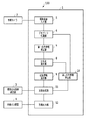
図1に示すブロック図を参照して、本実施形態の画像処理装置の構成を説明する。符号1は、多眼カメラにて撮影された複数枚の画像を合成するための画像処理装置である。符号2は、複数のデジタルカメラ等の画像取得装置をアレイ状に配置した多眼カメラである。符号3は、多眼カメラ2にて撮影された複数枚の撮影画像を合成する際の条件を設定するための画像合成条件設定部である。符号4は、画像を表示するためのディスプレイ等の画像出力装置である。
With reference to the block diagram shown in FIG. 1, the configuration of the image processing apparatus of this embodiment will be described.
符号5は、多眼カメラ2にて撮影された画像データを、画像処理装置1に読み込むための撮影画像入力部である。符号6は、撮影画像入力部5にて入力された画像データに対し、デモザイク処理を行うためのデモザイク処理部である。符号7は、デモザイク処理部6にてデモザイク処理を行った撮影画像を用い、後述する対応点算出に用いるための第一の色情報(本実施例では輝度値としている)を算出するための第一の色情報算出部である。符号8は、第一の色情報算出部7にて算出した各画素の第一の色情報を用いて、撮影画像間の対応点を算出するための対応点算出部である。符号9は、対応点算出部8にて算出した対応点情報を用いて、被写体の距離情報(被写体の奥行き情報)を算出するための距離情報算出部である。符号10は、デモザイク処理部6にてデモザイク処理を行った撮影画像と、対応点算出部8にて算出した対応点情報とを用いて、被写体の第二の色情報(本実施例では分光反射率としている)を算出するための第二の色情報算出部である。第二の色情報は、被写体の忠実な色情報であり、被写体の色を忠実に再現するために用いられる情報である。符号11は、画像合成条件設定部3に設定された画像合成条件と、距離情報算出部9にて算出した距離情報と、第二の色情報算出部10にて算出した第二の色情報とを用いて、出力用の合成画像を作成するための画像合成部である。符号12は、画像合成部11にて作成した合成画像を、画像表示装置4にて表示するために出力する画像出力部である。
符号100は、上記の構成を備える多眼カメラシステムである。なお、多眼カメラ2及び画像出力装置4は、画像処理装置1との接続を切り離すことも可能である。
なお、本実施例において、第一の色情報を輝度値とし、第二の色情報を分光反射率としているが、これに限定されない。第一の色情報は、例えば、Lab値やsRGB(standard RGB)値でもよく、複数の画像間の画素値を共通の色空間における色情報に変換したものであればよい。また、第二の色情報は、例えば、分光放射輝度などの他の分光情報であってもよく、RGBなどだけでは表現できない被写体の色を忠実に再現するため情報であればよい。 In the present embodiment, the first color information is a luminance value, and the second color information is a spectral reflectance. However, the present invention is not limited to this. The first color information may be, for example, a Lab value or an sRGB (standard RGB) value, as long as pixel values between a plurality of images are converted into color information in a common color space. The second color information may be other spectral information such as spectral radiance, for example, and may be information for faithfully reproducing a subject color that cannot be expressed by RGB alone.
図2は、多眼カメラシステム100にて行われる画像処理を示すフローチャートである。まず、S201では、多眼カメラ2にて、撮影対象である被写体を、複数の視点から撮影する。
FIG. 2 is a flowchart showing image processing performed in the
S202では、撮影画像入力部5は、S201で撮影された複数の撮影画像を画像処理装置1に読み込む。S203では、デモザイク処理部6は、S202で読み込んだ複数の撮影画像に対してデモザイク処理を行う。S204では、第一の色情報算出部7は、S203でデモザイク処理された画像の各画素について、第一の色情報である輝度値を算出する(詳細は後述)。S205では、対応点算出部8は、S204で算出した輝度信号を用いて、複数の画像間の対応点を算出する(詳細は後述)。S206は、距離情報算出部9にて、S205で算出した対応点情報を用いて、各画素の距離情報を算出する(詳細は後述)。S207では、第二の色情報算出部10は、S203でデモザイク処理した画像の各画素について、第二の色情報である分光反射率をS205にて算出した対応点情報を用いて算出する(詳細は後述)。
In S <b> 202, the photographed
S208では、ユーザからの指示又は外部装置からのコマンドに応じて、画像合成条件設定部3は、S202で読み込まれた複数の撮影画像の合成のための条件設定を行う。
In S208, the image composition
S209では、画像合成部11は、S206にて算出した距離情報と、S207にて算出した第二の色情報とを用いて、S208にて設定した合成条件に基づき、画像合成を行う(詳細は後述)。S210では、画像出力部12は、S209にて合成した合成画像を画像出力装置4に出力する。
In step S209, the
<多眼カメラのカラーフィルタ構成>
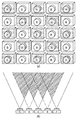
図3に、一実施形態における多眼カメラ2のカラーフィルタ構成を示す。図3(a)には、例として、5×5台の、合計25台の単眼カメラを並べ、多眼カメラ2を構成した例を図示している。図3(a)では、フィルタセットAを搭載した単眼カメラと、フィルタセットBを搭載した単眼カメラを市松状に配置している。すなわち、フィルタセットAを搭載した単眼カメラと、フィルタセットBを搭載した単眼カメラは、交互に配置されている。各単眼カメラをこのように配置することによって、各単眼カメラで撮影された撮影画像を合成する際に、冗長なデータを合成するという無駄を低減させることができる。
<Color filter configuration of multi-view camera>
FIG. 3 shows the color filter configuration of the
ここで、例えば、フィルタセットAの透過特性は、図4(a)に示した3色のカラーフィルタ(f_A1, f_A2, f_A3)、フィルタセットBの透過特性は、図4(b)に示した3色のカラーフィルタ(f_B1, f_B2, f_B3)を用いる。図4において、各単眼カメラの画角および単眼カメラ間の距離に応じて、フィルタセットAを搭載したカメラと、フィルタセットBを搭載したカメラの画角がオーバーラップしている。図3(b)中の斜線で示す領域は、被写体において各カメラの画角がオーバーラップしている領域の例を示している。このように画角がオーバラップしていることにより、6色分のカラーフィルタの情報を取得することが可能となる。 Here, for example, the transmission characteristics of the filter set A are the three color filters (f_A1, f_A2, and f_A3) shown in FIG. 4A, and the transmission characteristics of the filter set B are shown in FIG. 4B. Three color filters (f_B1, f_B2, f_B3) are used. In FIG. 4, the angle of view of the camera equipped with the filter set A and the angle of view of the camera equipped with the filter set B overlap each other according to the angle of view of each monocular camera and the distance between the monocular cameras. A region indicated by diagonal lines in FIG. 3B shows an example of a region where the angle of view of each camera overlaps in the subject. Thus, by overlapping the angles of view, it is possible to acquire information on the color filters for six colors.
また、本実施例では、6色のカラーフィルタが3色ずつの2セットのフィルタセットに分けられている。また、各単眼カメラは、これらのフィルタセットのうちいずれかを搭載し、マルチバンドで撮影を行う。そのため、全てのカメラに6色フィルタを搭載した場合に比べ、高い解像度での撮影が可能である。 In this embodiment, the six color filters are divided into two filter sets of three colors. Each monocular camera is equipped with one of these filter sets and performs multiband shooting. Therefore, it is possible to shoot at a higher resolution than when all cameras are equipped with a six-color filter.
なお、本実施例では、フィルタセットは2種類であるが、これに限定されない。3種類以上(すなわち、2種類以上)のフィルタセットのいずれかを各単眼カメラが搭載していることとしても良い。 In this embodiment, there are two types of filter sets, but the present invention is not limited to this. Each monocular camera may be equipped with any of three or more (that is, two or more) filter sets.
<輝度信号の算出>
ここでは、S204における第一の色情報の算出処理として、輝度信号の算出処理について詳細に説明する。
<Calculation of luminance signal>
Here, the luminance signal calculation process will be described in detail as the first color information calculation process in S204.
本実施例においては、多眼カメラ2を構成する各単眼カメラにより撮影されたそれぞれの撮影画像から、単独で輝度信号(Y値)を算出可能な構成としている。例えば、1つの単眼カメラで図4(a)に示すような、3色のフィルタ(f_A1, f_A2, f_A3)を用いて撮影した場合を考える。この時、画像中の座標(i, j)における画素の輝度値Y(i,j)Aは、デモザイク処理後の画素値(VA1, VA2, VA3)を用いて、次の式にて算出する。
In this embodiment, the luminance signal (Y value) can be calculated independently from each captured image captured by each monocular camera constituting the

この時、最適化に用いる被写体を、フィルタセットAおよびBで共通化することにより、同一輝度の被写体に対して、同一の輝度値を算出することが可能となり、後述する対応点探索の精度が向上する。 At this time, by sharing the subject used for optimization with the filter sets A and B, it becomes possible to calculate the same luminance value for the subject having the same luminance, and the accuracy of the corresponding point search described later is improved. improves.
ただし、画素値を輝度値へ変換するための上記の方法は、式(1)および(2)のような線形変換に限られるものではなく、例えば、下記の式(3)および式(4)のように、2次項を使用し、センサ出力の非線形性を補正するような変換を行ってもよい。 However, the above-described method for converting the pixel value into the luminance value is not limited to the linear conversion as in the expressions (1) and (2), and for example, the following expressions (3) and (4) As described above, the conversion may be performed using the quadratic term to correct the nonlinearity of the sensor output.
なお、第一の色情報がLab値やsRGBである場合も、画素値から所定の係数を用いて算出するなど、既知の方法を用いて第一の色情報を算出することができる。 Even when the first color information is a Lab value or sRGB, the first color information can be calculated using a known method, such as calculating from a pixel value using a predetermined coefficient.
<対応点の算出>
ここでは、S205における、複数画像間の対応点の算出処理について詳細に説明する。複数画像間の対応点は、当該複数の画像間の第一の色情報の差分を用いて算出される。
<Calculation of corresponding points>
Here, the calculation process of corresponding points between a plurality of images in S205 will be described in detail. Corresponding points between the plurality of images are calculated using a difference in the first color information between the plurality of images.
図6(a)は、被写体と複数のカメラ(多眼カメラ)との位置関係を示す図である。ただし、ここでは、簡単のため、多眼カメラを3台として説明する。中央のカメラ603には、カラーフィルタとして、フィルタセットA(f_A1, f_A2, f_A3)、左右2台のカメラ602および604にはフィルタセットB(f_B1, f_B2, f_B3)が搭載されているものとする。
FIG. 6A is a diagram illustrating a positional relationship between a subject and a plurality of cameras (multi-lens cameras). However, here, for the sake of simplicity, description will be made assuming that there are three multi-lens cameras. The
図6(b)は、被写体601をそれぞれカメラ602、603、および604で撮影した画像を示している。ここで、中央にあるカメラ603では、被写体上の点L、M、Nの全てが撮影されている。これに対し、カメラ602では、点L、Mは撮影されているものの、点Nは、オクルージョンにより撮影されていない。一方、カメラ604では、点M、Nは撮影されているものの、点Lは撮影されていない。そこで、第一の色情報を用いて、ステレオマッチング法等、パターンマッチング手法により、中央のカメラ603を基準とし、対応点を探索する。この場合、点Lの対応点は、カメラ602の撮影画像より求め、点Nの対応点は、カメラ604の撮影画像より求める。その結果、あるカメラでは撮影されているものの、他のカメラでは他の被写体の陰となり撮影されない、所謂、オクルージョンの影響を受けずに、対応点を算出し、色情報の再現や後述の距離情報算出処理を行うことができる。
FIG. 6B shows images obtained by photographing the subject 601 with the
<距離情報の算出>
ここでは、S206における距離情報算出処理について詳細に説明する。図8(a)に示すような、2つのカメラ(カメラ1、およびカメラ2)により撮影された撮影データから距離情報を算出する方法を考える。ここで、カメラ1の光軸がZ軸と一致するように座標軸を設定する。また、カメラ1とカメラ2の光軸は平行であり、X軸に平行に並んでいるものとする。図8(b)は、図8(a)をX-Z平面に投影した図である。3次元空間における、カメラ1の焦点を原点としたときの被写体のある一点の座標を(XO, YO, ZO)とする。また、カメラ1の撮影画像の中心を原点としたときに、被写体のこの一点が、カメラ1の撮影画像で結像する点の座標を(xL, yL)とする。さらに、カメラ2の撮影画像の中心を原点としたときに、被写体のこの一点(対応点)が、カメラ2の撮影画像で結像する点の座標を(xR, yR)とする。このとき、次の式(5)が成り立つ。
<Calculation of distance information>
Here, the distance information calculation process in S206 will be described in detail. Consider a method of calculating distance information from image data captured by two cameras (
![]()
![]()
<分光反射率の算出>
ここでは、S207における第二の色情報の算出処理として、分光反射率の算出処理について詳細に説明する。多眼カメラにて撮影された複数枚の撮影画像は、S205において、画素ごとに、画像間の対応点が算出されている。従って、各画素の色情報は、1枚の画像では、3色の色情報しか持たないものの、他の画像の対応点の情報を用いることにより、6色の色情報を持つことになる。そこで、各画素の分光反射率は、6色分の画素データ(VA1, VA2, VA3, VB1, VB2, VB3)を用いて、次の式(8)にて算出する。
<Calculation of spectral reflectance>
Here, the spectral reflectance calculation process will be described in detail as the second color information calculation process in S207. In a plurality of photographed images photographed by the multi-lens camera, corresponding points between images are calculated for each pixel in S205. Therefore, although the color information of each pixel has only three color information in one image, it has six color information by using the corresponding point information of other images. Therefore, the spectral reflectance of each pixel is calculated by the following equation (8) using pixel data for six colors (V A1 , V A2 , V A3 , V B1 , V B2 , V B3 ).
<画像合成処理>
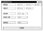
ここでは、S209における画像合成処理について詳細に説明する。本実施例においては、上述したように、多眼カメラによって撮影した画像(すなわち、撮影画像入力部5から読み込まれた撮影画像)間の対応点を算出することにより、各画素についての距離情報および分光情報を算出可能である。また、予め、S208にて、例えば図9に示すようなユーザーインターフェース(以下UIと記す)により合成条件が入力され、画像合成条件設定部3に当該条件が設定されている。画像合成部11は、該合成条件に基づき、距離情報及び分光情報を用いて、撮影画像入力部5から読み込まれた複数枚の撮影画像を1枚の画像に合成する。
<Image composition processing>
Here, the image composition processing in S209 will be described in detail. In the present embodiment, as described above, by calculating corresponding points between images captured by the multi-lens camera (that is, captured images read from the captured image input unit 5), distance information about each pixel and Spectral information can be calculated. Further, in S208, for example, a synthesis condition is input through a user interface (hereinafter referred to as UI) as shown in FIG. 9, for example, and the condition is set in the image synthesis
詳細には、まず、画像合成条件設定部3に設定された視点位置および視線方向により、カメラと被写体の幾何学的な配置が決定される。
Specifically, first, the geometric arrangement of the camera and the subject is determined based on the viewpoint position and the line-of-sight direction set in the image composition
次に、画像合成条件設定部3に設定された焦点距離に応じて、図10に示すように、フォーカスの合う距離が決定し、設定された絞り値に応じて、焦点距離からずれた位置にある被写体のボケ量を決定する。すなわち、絞り値が大きい場合には、図10(a)に示すように、焦点距離から離れた点のボケ量は大きくなり、絞り値が小さくなるにつれ、図10(b)に示すように、焦点距離から離れた点のボケ量は小さくなる。S206で算出された被写体の距離情報に応じたボケ量になるよう、ボケを生じさせるフィルタ等のパラメータを決定する。
Next, as shown in FIG. 10, the in-focus distance is determined according to the focal length set in the image composition
最後に、画像合成条件設定部3に設定された再現時の照明条件に応じて、S207で算出された被写体の分光反射率特性を合成される画像に掛け合わせることで、再現画像の色を算出することができる。その後、上記決定したパラメータを用いたフィルタ及び算出された再現画像の色により、合成画像を生成する。
Finally, in accordance with the illumination conditions at the time of reproduction set in the image composition
上述の通り、画像合成時の条件を設定することにより、当該条件に応じた合成画像を作成することが可能となる。 As described above, by setting the conditions for image composition, it is possible to create a composite image according to the conditions.
ただし、画像の合成条件を設定する方法は、ユーザが画像合成に必要な条件を十分に設定可能な方法であればよく、図9に示すUIに限定されるものではない。 However, the method for setting the image composition conditions is not limited to the UI shown in FIG. 9 as long as the user can sufficiently set the conditions necessary for image composition.
以上説明した処理制御を行うことで、多眼カメラによる撮影において、解像度を低下させずにマルチバンド撮影が可能である。また、フィルタセット構成が異なるカメラにより得られた画像データから被写体の分光情報を取得しつつ、当該画像データ間の対応点を高精度に算出することが可能である。 By performing the processing control described above, multiband shooting can be performed without reducing the resolution in shooting with a multi-view camera. In addition, it is possible to calculate the corresponding points between the image data with high accuracy while acquiring the spectral information of the subject from the image data obtained by cameras having different filter set configurations.
実施例1では、多眼カメラにより撮影された画像を、任意の視点位置、視線方向、焦点距離、絞り値、観察光源等を設定し、新たな画像として合成・出力する方法について説明した。実施例2では、多眼カメラにより撮影された画像から距離情報及び第二の色情報を算出し、アーカイブ画像として記録する方法について説明する。 In the first embodiment, the method of setting an arbitrary viewpoint position, line-of-sight direction, focal length, aperture value, observation light source, and the like, and synthesizing and outputting the image taken by the multi-view camera as a new image has been described. In the second embodiment, a method of calculating distance information and second color information from an image photographed by a multi-lens camera and recording it as an archive image will be described.
実施例2における画像処理装置のブロック図を図11に示す。尚、画像処理装置1、多眼カメラ2、および、撮影画像入力部5から第二の色情報算出部10までは、実施例1における画像処理装置と同一であるため、説明を省略する。
FIG. 11 shows a block diagram of the image processing apparatus according to the second embodiment. Since the
図11において、符号1101は、モザイク処理部6で処理された画像データと、距離情報算出部9で算出された距離情報と、第二の色情報算出部10にて算出された第二の色情報とを合成するための画像合成部である。符号1102は、多眼カメラにて撮影された複数枚の撮影画像を合成する際の条件を設定するための合成条件設定部である。符号1103は、画像合成部1101にて合成された画像データを記憶しておくための画像データ記憶部である。
In FIG. 11,
ここで、図12は、実施例2にて行われる画像処理のフローチャートである。以下、実施例2の実施形態を、図面を用いて詳細に説明する。ただし、S201における多眼カメラによる多視点画像撮影から、S207における第二の色情報算出までは、実施例1と同一であるため、説明を省略する。 Here, FIG. 12 is a flowchart of image processing performed in the second embodiment. Hereinafter, an embodiment of Example 2 will be described in detail with reference to the drawings. However, since the process from the multi-viewpoint image capturing by the multi-view camera in S201 to the second color information calculation in S207 is the same as that in the first embodiment, the description is omitted.
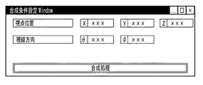
S1201では、画像合成条件設定部1102にて、複数画像を合成するための条件設定を行う。ここで、図13は、本実施例における合成条件設定のためのUIの一例である。本実施例では、画像データをアーカイブ画像として保存することを目的としているため、第一の実施例で設定した焦点距離、絞り値、照明光源に関する条件設定は不要である。
In step S1201, the image composition
S1202では、画像の各画素について、S206にて算出した距離情報、および、S207にて算出した第二の色情報を、例えば、図14に示すような情報に変換する。一般的な画像データは、図14(a)に示すように、位置(i, j)における情報は、RGB値すなわちR (i, j)、G(i, j)、B(i, j)のみである。一方、本実施例においては、このような情報に加えて、図14(b)に示すように、各画素の距離D(i, j)、および分光反射率R380 (i, j)〜R780 (i, j)を合成するものとする。 In S1202, for each pixel of the image, the distance information calculated in S206 and the second color information calculated in S207 are converted into information as shown in FIG. 14, for example. In general image data, as shown in FIG. 14A, information at a position (i, j) includes RGB values, that is, R (i, j), G (i, j), B (i, j). Only. On the other hand, in this embodiment, in addition to such information, as shown in FIG. 14B, the distance D (i, j) of each pixel and the spectral reflectances R 380 (i, j) to R 780 (i, j) shall be synthesized.
S1203では、S1202にて合成した画像データを、画像データ記憶部1103に記憶する。
In step S1203, the image data combined in step S1202 is stored in the image
以上説明した処理制御を行うことで、多眼カメラを用いた画像撮データから、被写体の距離情報、および、分光情報を持つ画像データを記録することが可能となる。 By performing the processing control described above, it is possible to record image data having subject distance information and spectral information from image data using a multi-lens camera.
<他の実施例>
上記、実施例1および実施例2において、フィルタ構成は、フィルタセットAとして3種類、フィルタセットBとして3種類のカラーフィルタを用いるとして説明したが、これに限定されるものではない。すなわち、4種類以上のカラーフィルタを、異なる種類のフィルタセットに分類し、かつ、各カメラに搭載されるフィルタセットが、それぞれ同一の色情報を算出可能な構成であれば、その詳細を限定するものではない。
<Other embodiments>
In the first and second embodiments, the filter configuration has been described as using three types of color filters as the filter set A and three types of color filters as the filter set B. However, the present invention is not limited to this. That is, if four or more types of color filters are classified into different types of filter sets, and the filter sets mounted on each camera can calculate the same color information, the details are limited. It is not a thing.
また、本発明は、以下の処理を実行することによっても実現される。即ち、上述した実施形態の機能を実現するソフトウェア(プログラム)を、ネットワーク又は各種記憶媒体を介してシステム或いは装置に供給し、そのシステム或いは装置のコンピュータ(またはCPUやMPU等)がプログラムを読み出して実行する処理である。 The present invention can also be realized by executing the following processing. That is, software (program) that realizes the functions of the above-described embodiments is supplied to a system or apparatus via a network or various storage media, and a computer (or CPU, MPU, or the like) of the system or apparatus reads the program. It is a process to be executed.
Claims (9)
前記複数の撮影画像の画素値から共通の色空間における色情報である第一の色情報を算出する第一の色情報算出手段と、
前記算出された第一の色情報を用いて、前記複数の撮影画像間の対応点を算出することで前記複数の撮影画像における被写体の奥行き情報を算出する距離情報算出手段と、
前記被写体の色を再現するために用いられる色情報である第二の色情報を前記複数の撮影画像の画素値から算出する第二の色情報算出手段と、
前記算出された奥行き情報及び第二の色情報を用いて、前記複数の撮影画像を合成する合成手段と
を備えることを特徴とする画像処理装置。 An image processing apparatus that processes data of a plurality of captured images captured by a multi-lens camera in which cameras equipped with any of two or more types of filter sets are arranged in an array,
First color information calculation means for calculating first color information which is color information in a common color space from pixel values of the plurality of captured images;
Distance information calculating means for calculating depth information of a subject in the plurality of captured images by calculating corresponding points between the plurality of captured images using the calculated first color information;
Second color information calculating means for calculating second color information, which is color information used for reproducing the color of the subject, from pixel values of the plurality of captured images;
An image processing apparatus comprising: a combining unit that combines the plurality of captured images using the calculated depth information and second color information.
前記合成手段は、前記入力された合成条件に基づいて合成を行うことを特徴とする請求項1乃至4のいずれか1項に記載の画像処理装置。 Comprising synthesis condition setting means for inputting a synthesis condition of the plurality of captured images;
The image processing apparatus according to claim 1, wherein the synthesis unit performs synthesis based on the input synthesis condition.
前記多眼カメラにより撮影された複数の撮影画像の画素値から共通の色空間における色情報である第一の色情報を算出する第一の色情報算出手段と、
前記算出された第一の色情報を用いて、前記複数の撮影画像間の対応点を算出することで前記複数の撮影画像における被写体の奥行き情報を算出する距離情報算出手段と、
前記被写体の色を再現するために用いられる色情報である第二の色情報を前記複数の撮影画像の画素値から算出する第二の色情報算出手段と、
前記算出された奥行き情報及び第二の色情報を用いて、前記複数の撮影画像を合成する合成手段と
を備えることを特徴とする多眼カメラシステム。 A multi-lens camera in which cameras equipped with any one of two or more filter sets are arranged in an array;
First color information calculating means for calculating first color information that is color information in a common color space from pixel values of a plurality of captured images captured by the multi-lens camera;
Distance information calculating means for calculating depth information of a subject in the plurality of captured images by calculating corresponding points between the plurality of captured images using the calculated first color information;
Second color information calculating means for calculating second color information, which is color information used for reproducing the color of the subject, from pixel values of the plurality of captured images;
A multi-lens camera system comprising: a combining unit that combines the plurality of captured images using the calculated depth information and second color information.
前記複数の撮影画像の画素値から共通の色空間における色情報である第一の色情報を算出する第一の色情報算出ステップと、
前記算出された第一の色情報を用いて、前記複数の撮影画像間の対応点を算出することで前記複数の撮影画像における被写体の奥行き情報を算出する距離情報算出ステップと、
前記被写体の色を再現するために用いられる色情報である第二の色情報を前記複数の撮影画像の画素値から算出する第二の色情報算出ステップと、
前記算出された奥行き情報及び第二の色情報を用いて、前記複数の撮影画像を合成する合成ステップと
を含むことを特徴とする画像処理方法。 An image processing method for processing data of a plurality of photographed images photographed by a multi-lens camera in which cameras equipped with any one of two or more filter sets are arranged in an array,
A first color information calculation step of calculating first color information which is color information in a common color space from pixel values of the plurality of captured images;
A distance information calculating step of calculating depth information of a subject in the plurality of captured images by calculating corresponding points between the plurality of captured images using the calculated first color information;
A second color information calculation step of calculating second color information, which is color information used for reproducing the color of the subject, from pixel values of the plurality of captured images;
An image processing method comprising: a combining step of combining the plurality of captured images using the calculated depth information and second color information.
Priority Applications (2)
| Application Number | Priority Date | Filing Date | Title |
|---|---|---|---|
| JP2011050092A JP5704975B2 (en) | 2011-03-08 | 2011-03-08 | Image processing apparatus, image processing method, and program |
| US13/409,045 US9008412B2 (en) | 2011-03-08 | 2012-02-29 | Image processing device, image processing method and recording medium for combining image data using depth and color information |
Applications Claiming Priority (1)
| Application Number | Priority Date | Filing Date | Title |
|---|---|---|---|
| JP2011050092A JP5704975B2 (en) | 2011-03-08 | 2011-03-08 | Image processing apparatus, image processing method, and program |
Publications (3)
| Publication Number | Publication Date |
|---|---|
| JP2012186755A JP2012186755A (en) | 2012-09-27 |
| JP2012186755A5 JP2012186755A5 (en) | 2014-04-17 |
| JP5704975B2 true JP5704975B2 (en) | 2015-04-22 |
Family
ID=46795632
Family Applications (1)
| Application Number | Title | Priority Date | Filing Date |
|---|---|---|---|
| JP2011050092A Active JP5704975B2 (en) | 2011-03-08 | 2011-03-08 | Image processing apparatus, image processing method, and program |
Country Status (2)
| Country | Link |
|---|---|
| US (1) | US9008412B2 (en) |
| JP (1) | JP5704975B2 (en) |
Families Citing this family (11)
| Publication number | Priority date | Publication date | Assignee | Title |
|---|---|---|---|---|
| JP5926626B2 (en) | 2012-06-11 | 2016-05-25 | キヤノン株式会社 | Image processing apparatus, control method therefor, and program |
| JP6082556B2 (en) * | 2012-09-28 | 2017-02-15 | 日立オートモティブシステムズ株式会社 | Imaging device |
| US9183261B2 (en) | 2012-12-28 | 2015-11-10 | Shutterstock, Inc. | Lexicon based systems and methods for intelligent media search |
| US9183215B2 (en) | 2012-12-29 | 2015-11-10 | Shutterstock, Inc. | Mosaic display systems and methods for intelligent media search |
| JP6240012B2 (en) | 2014-03-26 | 2017-11-29 | キヤノン株式会社 | Color processing apparatus and method |
| JP6154781B2 (en) * | 2014-05-22 | 2017-06-28 | 日本電信電話株式会社 | Image processing method and image processing system |
| JP5896090B1 (en) * | 2014-05-28 | 2016-03-30 | コニカミノルタ株式会社 | Imaging apparatus and colorimetric method |
| JP6646456B2 (en) | 2016-02-10 | 2020-02-14 | キヤノン株式会社 | Color processing apparatus and method |
| CN105786016B (en) * | 2016-03-31 | 2019-11-05 | 深圳奥比中光科技有限公司 | The processing method of unmanned plane and RGBD image |
| CN107666606B (en) * | 2016-07-29 | 2019-07-12 | 东南大学 | Binocular panoramic picture acquisition methods and device |
| CN114710617B (en) * | 2022-03-18 | 2023-09-05 | 珠海思奇科技有限公司 | Photographing method, photographing system, photographing equipment and photographing storage medium for dual-axis array camera |
Family Cites Families (13)
| Publication number | Priority date | Publication date | Assignee | Title |
|---|---|---|---|---|
| AU5908000A (en) * | 1999-07-02 | 2001-01-22 | Hypermed Imaging, Inc. | Imaging apparatus with means for fusing thermal and hyperspectral images |
| JP2003333355A (en) | 2002-05-10 | 2003-11-21 | Canon Inc | Color evaluation apparatus and method |
| US7433102B2 (en) | 2002-05-10 | 2008-10-07 | Canon Kabushiki Kaisha | Reproduction color prediction apparatus and method |
| JP3875660B2 (en) | 2003-07-29 | 2007-01-31 | 株式会社東芝 | Multi electrostatic camera module |
| JP2005059362A (en) | 2003-08-11 | 2005-03-10 | Canon Inc | Method of generating color separation data and image forming apparatus |
| JP2006254368A (en) | 2005-03-14 | 2006-09-21 | Canon Inc | Color processing device and method thereof |
| US7718940B2 (en) * | 2005-07-26 | 2010-05-18 | Panasonic Corporation | Compound-eye imaging apparatus |
| US7609906B2 (en) * | 2006-04-04 | 2009-10-27 | Mitsubishi Electric Research Laboratories, Inc. | Method and system for acquiring and displaying 3D light fields |
| JP2008128771A (en) | 2006-11-20 | 2008-06-05 | Toppan Printing Co Ltd | Apparatus and method for simultaneously acquiring spectroscopic information and shape information |
| JP2009284188A (en) * | 2008-05-22 | 2009-12-03 | Panasonic Corp | Color imaging apparatus |
| JP5284138B2 (en) | 2009-02-20 | 2013-09-11 | キヤノン株式会社 | Image processing apparatus and image processing method |
| JP2010276469A (en) * | 2009-05-28 | 2010-12-09 | Konica Minolta Holdings Inc | Image processor and image processing method of ranging apparatus |
| US8581995B2 (en) * | 2011-01-25 | 2013-11-12 | Aptina Imaging Corporation | Method and apparatus for parallax correction in fused array imaging systems |
-
2011
- 2011-03-08 JP JP2011050092A patent/JP5704975B2/en active Active
-
2012
- 2012-02-29 US US13/409,045 patent/US9008412B2/en active Active
Also Published As
| Publication number | Publication date |
|---|---|
| US20120230549A1 (en) | 2012-09-13 |
| JP2012186755A (en) | 2012-09-27 |
| US9008412B2 (en) | 2015-04-14 |
Similar Documents
| Publication | Publication Date | Title |
|---|---|---|
| JP5704975B2 (en) | Image processing apparatus, image processing method, and program | |
| JP5751986B2 (en) | Image generation device | |
| JP6299124B2 (en) | Projection system, image processing apparatus, projection method, and program | |
| JP6021541B2 (en) | Image processing apparatus and method | |
| JP5687608B2 (en) | Image processing apparatus, image processing method, and image processing program | |
| JP5984493B2 (en) | Image processing apparatus, image processing method, imaging apparatus, and program | |
| JPH09181913A (en) | Camera system | |
| JP6257285B2 (en) | Compound eye imaging device | |
| JP5704984B2 (en) | Imaging device | |
| JP6478511B2 (en) | Image processing method, image processing apparatus, compound eye imaging apparatus, image processing program, and storage medium | |
| JP5406151B2 (en) | 3D imaging device | |
| JP2013009274A (en) | Image processing device, image processing method, and program | |
| JP2010063067A (en) | Image processing device and method, and program | |
| KR101626447B1 (en) | An apparatus, a method, a computer-readable medium storing a computer program of removing lens distortion and chromatic aberration | |
| JP2009258005A (en) | Three-dimensional measuring device and three-dimensional measuring method | |
| JP2013247543A (en) | Imaging device, display device, image processing method and program | |
| US20150042782A1 (en) | Image processing apparatus, imaging apparatus, microscope system, image processing method, and computer readable recording medium | |
| JP6732440B2 (en) | Image processing apparatus, image processing method, and program thereof | |
| WO2019045876A1 (en) | Multi-source video stabilization | |
| JP6648916B2 (en) | Imaging device | |
| JP5744642B2 (en) | Image processing apparatus, image processing method, and program. | |
| JP2013175821A (en) | Image processing device, image processing method, and program | |
| KR102505659B1 (en) | Three demension scanning apparatus using light based on smartphone | |
| JP6585890B2 (en) | Image processing apparatus, image processing method and program, and imaging apparatus | |
| JP6103767B2 (en) | Image processing apparatus, method, and program |
Legal Events
| Date | Code | Title | Description |
|---|---|---|---|
| A521 | Request for written amendment filed |
Free format text: JAPANESE INTERMEDIATE CODE: A523 Effective date: 20140304 |
|
| A621 | Written request for application examination |
Free format text: JAPANESE INTERMEDIATE CODE: A621 Effective date: 20140304 |
|
| A977 | Report on retrieval |
Free format text: JAPANESE INTERMEDIATE CODE: A971007 Effective date: 20141125 |
|
| A131 | Notification of reasons for refusal |
Free format text: JAPANESE INTERMEDIATE CODE: A131 Effective date: 20141202 |
|
| A521 | Request for written amendment filed |
Free format text: JAPANESE INTERMEDIATE CODE: A523 Effective date: 20141215 |
|
| TRDD | Decision of grant or rejection written | ||
| A01 | Written decision to grant a patent or to grant a registration (utility model) |
Free format text: JAPANESE INTERMEDIATE CODE: A01 Effective date: 20150127 |
|
| A61 | First payment of annual fees (during grant procedure) |
Free format text: JAPANESE INTERMEDIATE CODE: A61 Effective date: 20150224 |
|
| R151 | Written notification of patent or utility model registration |
Ref document number: 5704975 Country of ref document: JP Free format text: JAPANESE INTERMEDIATE CODE: R151 |