JP5699340B2 - Rotation control type deployment device - Google Patents
Rotation control type deployment device Download PDFInfo
- Publication number
- JP5699340B2 JP5699340B2 JP2012535249A JP2012535249A JP5699340B2 JP 5699340 B2 JP5699340 B2 JP 5699340B2 JP 2012535249 A JP2012535249 A JP 2012535249A JP 2012535249 A JP2012535249 A JP 2012535249A JP 5699340 B2 JP5699340 B2 JP 5699340B2
- Authority
- JP
- Japan
- Prior art keywords
- screw
- release
- handle
- pusher assembly
- clamp
- Prior art date
- Legal status (The legal status is an assumption and is not a legal conclusion. Google has not performed a legal analysis and makes no representation as to the accuracy of the status listed.)
- Active
Links
- 230000000717 retained effect Effects 0.000 claims 1
- 230000014759 maintenance of location Effects 0.000 description 16
- 210000005166 vasculature Anatomy 0.000 description 16
- 230000002439 hemostatic effect Effects 0.000 description 6
- 238000000034 method Methods 0.000 description 6
- 210000000709 aorta Anatomy 0.000 description 4
- 210000000702 aorta abdominal Anatomy 0.000 description 1
- 230000017531 blood circulation Effects 0.000 description 1
- 230000006835 compression Effects 0.000 description 1
- 238000007906 compression Methods 0.000 description 1
- 230000000994 depressogenic effect Effects 0.000 description 1
- 230000007717 exclusion Effects 0.000 description 1
- 238000010348 incorporation Methods 0.000 description 1
- 239000000463 material Substances 0.000 description 1
- 238000000926 separation method Methods 0.000 description 1
- 230000002792 vascular Effects 0.000 description 1
- 210000003462 vein Anatomy 0.000 description 1
Images


Classifications
-
- A—HUMAN NECESSITIES
- A61—MEDICAL OR VETERINARY SCIENCE; HYGIENE
- A61F—FILTERS IMPLANTABLE INTO BLOOD VESSELS; PROSTHESES; DEVICES PROVIDING PATENCY TO, OR PREVENTING COLLAPSING OF, TUBULAR STRUCTURES OF THE BODY, e.g. STENTS; ORTHOPAEDIC, NURSING OR CONTRACEPTIVE DEVICES; FOMENTATION; TREATMENT OR PROTECTION OF EYES OR EARS; BANDAGES, DRESSINGS OR ABSORBENT PADS; FIRST-AID KITS
- A61F2/00—Filters implantable into blood vessels; Prostheses, i.e. artificial substitutes or replacements for parts of the body; Appliances for connecting them with the body; Devices providing patency to, or preventing collapsing of, tubular structures of the body, e.g. stents
- A61F2/95—Instruments specially adapted for placement or removal of stents or stent-grafts
- A61F2/962—Instruments specially adapted for placement or removal of stents or stent-grafts having an outer sleeve
- A61F2/966—Instruments specially adapted for placement or removal of stents or stent-grafts having an outer sleeve with relative longitudinal movement between outer sleeve and prosthesis, e.g. using a push rod
-
- A—HUMAN NECESSITIES
- A61—MEDICAL OR VETERINARY SCIENCE; HYGIENE
- A61F—FILTERS IMPLANTABLE INTO BLOOD VESSELS; PROSTHESES; DEVICES PROVIDING PATENCY TO, OR PREVENTING COLLAPSING OF, TUBULAR STRUCTURES OF THE BODY, e.g. STENTS; ORTHOPAEDIC, NURSING OR CONTRACEPTIVE DEVICES; FOMENTATION; TREATMENT OR PROTECTION OF EYES OR EARS; BANDAGES, DRESSINGS OR ABSORBENT PADS; FIRST-AID KITS
- A61F2/00—Filters implantable into blood vessels; Prostheses, i.e. artificial substitutes or replacements for parts of the body; Appliances for connecting them with the body; Devices providing patency to, or preventing collapsing of, tubular structures of the body, e.g. stents
- A61F2/95—Instruments specially adapted for placement or removal of stents or stent-grafts
- A61F2/9517—Instruments specially adapted for placement or removal of stents or stent-grafts handle assemblies therefor
-
- A—HUMAN NECESSITIES
- A61—MEDICAL OR VETERINARY SCIENCE; HYGIENE
- A61F—FILTERS IMPLANTABLE INTO BLOOD VESSELS; PROSTHESES; DEVICES PROVIDING PATENCY TO, OR PREVENTING COLLAPSING OF, TUBULAR STRUCTURES OF THE BODY, e.g. STENTS; ORTHOPAEDIC, NURSING OR CONTRACEPTIVE DEVICES; FOMENTATION; TREATMENT OR PROTECTION OF EYES OR EARS; BANDAGES, DRESSINGS OR ABSORBENT PADS; FIRST-AID KITS
- A61F2/00—Filters implantable into blood vessels; Prostheses, i.e. artificial substitutes or replacements for parts of the body; Appliances for connecting them with the body; Devices providing patency to, or preventing collapsing of, tubular structures of the body, e.g. stents
- A61F2/95—Instruments specially adapted for placement or removal of stents or stent-grafts
- A61F2/962—Instruments specially adapted for placement or removal of stents or stent-grafts having an outer sleeve
- A61F2/966—Instruments specially adapted for placement or removal of stents or stent-grafts having an outer sleeve with relative longitudinal movement between outer sleeve and prosthesis, e.g. using a push rod
- A61F2002/9665—Instruments specially adapted for placement or removal of stents or stent-grafts having an outer sleeve with relative longitudinal movement between outer sleeve and prosthesis, e.g. using a push rod with additional retaining means
Description
本発明は、医療装置に関し、より詳細にはステントグラフトの脈管内配備のための装置に関し、更に詳細にはその様な装置のための操作ハンドルに、関する。 The present invention relates to medical devices, and more particularly to devices for intravascular deployment of stent grafts, and more particularly to an operating handle for such devices.
(参考文献の援用)
以下の記述では下記の同時係属特許出願、即ち、
−PCT公報WO2003/101518「人工器官配備装置のためのトリガーワイヤシステム」−
を参照している。同出願の内容全体をこれにより参考文献としてここに援用する。
(Incorporation of references)
In the following description, the following co-pending patent applications:
-PCT publication WO2003 / 101518 "Trigger wire system for prosthesis deployment device"-
Refers to. The entire contents of that application are hereby incorporated herein by reference.
ステントグラフトのための導入器は、ステントグラフトを脈管内技法により配備できるように収縮状態に保持し、次いで患者の脈管構造内に正しく位置付けられたらステントグラフトを解放する装置である。 An introducer for a stent graft is a device that holds the stent graft in a contracted state so that it can be deployed by intravascular techniques and then releases the stent graft once properly positioned within the patient's vasculature.
ステントグラフトを脈管構造の所望の位置で導入器から解放するのに必要な一連の順次的動作が要求されている順序で始められ、その様な配備時における施術者の過失が起きにくいようになっていることが望ましい。
従って、本発明の目的は、ステントグラフトを一続きの順次的動作によって導入、配備、解放するように配設されている配備装置を提供することである。 Accordingly, it is an object of the present invention to provide a deployment device that is arranged to introduce, deploy, and release a stent graft in a series of sequential operations.
本明細書全体を通して、大動脈、配備装置又は人工器官の部分に関して遠位という用語は、大動脈、配備装置又は人工器官の心臓から遠ざかる血流方向に見てより遠い端を意味し、近位という用語は、大動脈、配備装置又は人工器官端部の心臓により近い部分を意味する。他の脈管への適用に際し、尾方と頭方の様な類似の用語もその様に理解されたい。 Throughout this specification, the term distal with respect to the part of the aorta, deployment device or prosthesis means the end farther in the direction of blood flow away from the heart of the aorta, deployment device or prosthesis, and the term proximal Means the part closer to the heart of the aorta, deployment device or prosthetic end. For other vascular applications, similar terms such as tail and head should be understood accordingly.
本発明について、概してステントグラフトの腹部大動脈内への配備に関して論じてゆくが、本発明はその様に限定されるものではなく、大動脈の他の部分への配備或いはヒト又は動物の身体の他の脈管への配備に適用することができる。 The present invention will be discussed generally with respect to deployment of a stent graft into the abdominal aorta, but the present invention is not so limited and may be deployed to other parts of the aorta or other veins of the human or animal body. Can be applied to pipe deployment.
本論考全体を通して、「ステントグラフト」という用語は、生体適合性グラフト材料の管状本体を有し当該管状本体に少なくとも1つのステントが締結されてステントグラフトを貫くルーメンが画定されている装置を意味するものとする。ステントグラフトは、二股に別れていてもよいし、開窓や側枝などを有していてもよい。ステントグラフトの他の配設も本発明の範囲に入る。 Throughout this discussion, the term “stent graft” shall mean a device having a tubular body of biocompatible graft material with at least one stent fastened to the lumen defining a lumen through the stent graft. To do. The stent graft may be divided into two branches or may have a fenestration or a side branch. Other arrangements of stent grafts are within the scope of the present invention.
本発明は、従って、1つの形態では、ハンドル組立体と、ステントグラフト配備装置と、当該ステントグラフト配備装置上に保持されているステントグラフトと、を組み合わせて備えている脈管内導入器において、前記ハンドル組立体は、第1部品と第2部品を含み、第2部品は第1部品に対して動かされるものであり、第1部品は使用者により把持及び保持される固定部分と回転させられる回転部分を備え、第1部品の回転部分と第2部品は協働する第1スクリューねじを備えており、それによって、第2部品を第1部品の回転部分に対して回転させると第1部品と第2部品の間に長手方向の相対移動が引き起こされ、前記配備装置は、ステントグラフトが搭載されているプッシャー組立体と、プッシャー組立体上にあるステントグラフトを覆い当該ステントグラフトをプッシャー組立体上に圧縮状態に保持するシースと、を含んでおり、シースはプッシャー組立体に対して相対的に動かすことができ、プッシャー組立体は第1部品に接続されシースは第2部品に接続されており、それによって、第2部品を第1部品に対してそれらの相互的回転により後退させると、シースがプッシャー組立体上のステントグラフトから少なくとも途中まで後退する、脈管内導入器に存すると言える。 The present invention, therefore, in one form, includes an intravascular introducer comprising a combination of a handle assembly, a stent graft deployment device, and a stent graft held on the stent graft deployment device. Comprises a first part and a second part, the second part being moved relative to the first part, the first part comprising a fixed part to be gripped and held by the user and a rotating part to be rotated The rotating part of the first part and the second part are provided with cooperating first screw screws so that when the second part is rotated relative to the rotating part of the first part, the first part and the second part A longitudinal relative movement is caused between the pusher assembly on which the stent graft is mounted and the stent graft on the pusher assembly. And a sheath that holds the stent graft in compression on the pusher assembly, the sheath being movable relative to the pusher assembly, the pusher assembly being connected to the first part and the sheath being Intravascular introduction, wherein the sheath is retracted at least partway from the stent graft on the pusher assembly when connected to the second part so that the second part is retracted by their mutual rotation relative to the first part It can be said that it exists in the vessel.
好適には、第1部品の固定部分はプッシャー組立体に係合し、第1部品の回転部分はプッシャー組立体の解放クランプに係合し、解放クランプはプッシャー組立体に対して長手方向に動かすことができ、プッシャー組立体の解放クランプには、ステントグラフトをプッシャー組立体から解放するためのトリガーワイヤが取り付けられており、それによって、第2要素を第1要素に対して動かすとプッシャーの解放クランプが動かされ、それによりトリガーワイヤが引かれて、ステントグラフトをプッシャー組立体から解放する。 Preferably, the fixed part of the first part engages the pusher assembly, the rotating part of the first part engages the release clamp of the pusher assembly, and the release clamp moves longitudinally relative to the pusher assembly. The release clamp of the pusher assembly is fitted with a trigger wire for releasing the stent graft from the pusher assembly so that when the second element is moved relative to the first element, the pusher release clamp Is moved, thereby pulling the trigger wire, releasing the stent graft from the pusher assembly.
好適には、第1部品の回転部分は第1部品の固定部分に対して回転し、回転部分は解放クランプの一部分を係合させる第2スクリューねじを含んでおり、それによって、第2部品を回転式に動かすと、解放クランプがプッシャー組立体に対して長手方向に動かされる。 Preferably, the rotating part of the first part rotates with respect to the fixed part of the first part, the rotating part including a second screw screw engaging a part of the release clamp, whereby the second part is When moved rotationally, the release clamp is moved longitudinally with respect to the pusher assembly.
好適には、回転部分は、内部円筒面を備えており、第1スクリューねじと第2スクリューねじはどちらも内部円筒面に形成されており、第1スクリューねじと第2スクリューねじは同じピッチを備え互いに同心である。 Preferably, the rotating portion has an inner cylindrical surface, and both the first screw screw and the second screw screw are formed on the inner cylindrical surface, and the first screw screw and the second screw screw have the same pitch. Be prepared and concentric with each other.
好適には、第1スクリューねじは、32mmのピッチを有する幅3mm高さ1mmの螺旋突起を第2要素の内部円筒面に備え、第2スクリューねじは、32mmのピッチを有する幅2mm深さ2mmの螺旋溝を第2要素の内部円筒面に備えている。 Preferably, the first screw screw is provided with a spiral projection having a pitch of 32 mm, a width of 3 mm and a height of 1 mm on the inner cylindrical surface of the second element, and the second screw screw has a pitch of 32 mm, a width of 2 mm and a depth of 2 mm. Are provided on the inner cylindrical surface of the second element.
第2部品側の協働する第1スクリューねじは、第2部品の長さの一部を延びていてもよいし、実質的に第2部品の全長さに亘って延びていてもよい。 The cooperating first screw screw on the second part side may extend part of the length of the second part, or may extend substantially over the entire length of the second part.
好適には、第1スクリューねじは、32mmのピッチを有する幅3mm高さ1mmの螺旋突起を第2要素の内部円筒面に備え、第2スクリューねじは、32mmのピッチを有する幅2mm深さ2mmの螺旋溝を第2要素の内部円筒面に備えている。 Preferably, the first screw screw is provided with a spiral projection having a pitch of 32 mm, a width of 3 mm and a height of 1 mm on the inner cylindrical surface of the second element, and the second screw screw has a pitch of 32 mm, a width of 2 mm and a depth of 2 mm. Are provided on the inner cylindrical surface of the second element.
好適には、装置は、第2部品に段状肩部を更に備えており、段状肩部は、第2部品の選択された量の長手方向移動が第1部品の相対回転により起こった後にプッシャー組立体の解放クランプに係合し、それにより解放クランプの当該部分を第2スクリューねじへ係合させ、それによりトリガーワイヤを引いてステントグラフトをプッシャー組立体から解放させ始めるように配設されている。 Preferably, the apparatus further comprises a stepped shoulder on the second part, the stepped shoulder after a selected amount of longitudinal movement of the second part has occurred by relative rotation of the first part. Arranged to engage the release clamp of the pusher assembly, thereby engaging that portion of the release clamp to the second screw screw, thereby pulling the trigger wire to begin releasing the stent graft from the pusher assembly. Yes.
好適には、第2部品は、シースのハブのためのバイオネットソケットを含んでおり、それによって、シース及びシースハブは第2部品と共に動き、また要求に応じてシースをバイオネットソケットから係合解除することができる。 Preferably, the second part includes a bayonet socket for the hub of the sheath so that the sheath and the sheath hub move with the second part and disengage the sheath from the bayonet socket as required. can do.
好適には、第1部品は実質的には円筒状であり、第2部品は管状であって第1部品内を滑動する。 Preferably, the first part is substantially cylindrical and the second part is tubular and slides within the first part.
好適には、管状第2部品は長手方向スロット及び内部ルーメンを有し、プッシャー組立体は長手方向のルーメン内を延びており、プッシャー組立体は、第1部品と係合するべく長手方向スロットを通って延びているアーム部を含んでおり、それによって、第2部品を第1部品に対して長手方向に動かすことができる。 Preferably, the tubular second part has a longitudinal slot and an internal lumen, the pusher assembly extends through the longitudinal lumen, and the pusher assembly has a longitudinal slot for engagement with the first part. An arm portion extending therethrough is included, whereby the second part can be moved longitudinally relative to the first part.
或る代わりの実施形態では、本発明は、使用者により把持及び保持される円筒状固定ハンドルと、当該固定ハンドルを通って延びる管状解放ハンドルとを、備えており、それによって、解放ハンドルを固定ハンドルの中を通して動かすことができる、ステントグラフト配備装置組立体において、配備装置は、更に、プッシャー組立体と、当該プッシャー組立体上にあるステントグラフトを覆うためのシースと、を含んでおり、プッシャー組立体は固定ハンドルに接続され、シースは解放ハンドルに接続されており、それによって、解放ハンドルを固定ハンドルの中を通して後退させるとシースがプッシャー組立体上のステントグラフトから後退するようになっており、前記固定ハンドルはプッシャー組立体を把持する把持要素と回転子要素とを含んでおり、回転子要素は、その内部円筒面に第1スクリューねじと第2スクリューねじとを備えており、第1スクリューねじと第2スクリューねじは同じピッチを備え互いに同心であり、前記管状解放ハンドルは、第1スクリューねじと係合できる外部スクリューねじを備えており、プッシャー組立体には解放クランプが在り、プッシャー組立体の解放クランプにはステントグラフトをプッシャー組立体から解放するためのトリガーワイヤが取り付けられており、解放クランプは第2スクリューねじと係合するピンを備えており、それによって、回転子要素を把持要素に対して動かすと、最初に管状解放ハンドルが把持要素に対して動かされ、続いてプッシャー組立体の解放クランプが動かされ、それによりトリガーワイヤが引かれる、ステントグラフト配備装置組立体を備えている。 In an alternative embodiment, the present invention comprises a cylindrical locking handle that is gripped and held by a user and a tubular release handle that extends through the locking handle, thereby locking the release handle. A stent graft deployment device assembly that can be moved through a handle, the deployment device further comprising a pusher assembly and a sheath for covering the stent graft overlying the pusher assembly, the pusher assembly. Is connected to the fixed handle, and the sheath is connected to the release handle so that when the release handle is retracted through the fixed handle, the sheath is retracted from the stent graft on the pusher assembly. The handle includes a gripping element and a rotor element for gripping the pusher assembly. The rotor element includes a first screw screw and a second screw screw on its inner cylindrical surface, and the first screw screw and the second screw screw have the same pitch and are concentric with each other, the tubular element The release handle includes an external screw screw that is engageable with the first screw screw, the pusher assembly includes a release clamp, and the release clamp of the pusher assembly includes a trigger wire for releasing the stent graft from the pusher assembly. And the release clamp includes a pin that engages the second screw screw so that when the rotor element is moved relative to the gripping element, the tubular release handle is first moved relative to the gripping element. Followed by the pusher assembly release clamp being moved, thereby pulling the trigger wire, And a tent graft deployment device assembly.
管状の解放ハンドルの外部スクリューねじは、管状の解放ハンドルの遠位端から同ハンドルの長さの一部を延びていてもよいし、実質的に管状の解放ハンドルの遠位端から同ハンドルの全長さに亘って延びていてもよい。管状の解放ハンドルの外部スクリューねじが、管状の解放ハンドルの遠位端から同ハンドルの長さの一部を延びている場合には、回転子の回転によるシースの後退は、外部スクリューねじが第1スクリューねじから係合解除されるまで起こり、係合解除された時点で、解放ハンドルを固定ハンドルの中を通して長手方向に動かすとシースの更なる後退が実現される。管状解放ハンドルの外部スクリューねじが実質的に管状解放ハンドルの全長さを延びている場合には、回転子要素を回転させることによりシースの完全退避が起こる。 The external screw screw of the tubular release handle may extend a portion of the length of the handle from the distal end of the tubular release handle, or from the distal end of the substantially tubular release handle. It may extend over the entire length. If the external screw screw of the tubular release handle extends part of the length of the handle from the distal end of the tubular release handle, the sheath retraction due to the rotation of the rotor will cause the external screw screw to This happens until the screw is disengaged from one screw screw, and when disengaged, the sheath is further retracted by moving the release handle longitudinally through the fixed handle. When the external screw thread of the tubular release handle extends substantially the entire length of the tubular release handle, complete sheath withdrawal occurs by rotating the rotor element.
好適には、第1スクリューねじは、32mmのピッチを有する幅3mm高さ1mmの螺旋突起を回転子要素の内部円筒面に備え、第2スクリューねじは、32mmのピッチを有する幅2mm深さ2mmの螺旋溝を回転子要素の内部円筒面に備え、第1スクリューねじと係合できる外部スクリューねじは、32mmのピッチを有する幅3mm深さ1mmの螺旋溝を備えている。 Preferably, the first screw screw comprises a spiral projection of 3 mm width and 1 mm height having a pitch of 32 mm on the inner cylindrical surface of the rotor element, and the second screw screw has a width of 2 mm and a depth of 2 mm having a pitch of 32 mm. The external screw screw that can be engaged with the first screw screw has a spiral groove with a pitch of 32 mm, a width of 3 mm, and a depth of 1 mm.
好適には、解放ハンドルは、シースのハブのためのバイオネットソケットを含んでいる。 Preferably, the release handle includes a bayonet socket for the sheath hub.
好適には、固定ハンドルは、当該ハンドルを貫く実質的に円筒状の内腔を備えており、解放ハンドルは管状であって、固定ハンドル内を滑動する。 Preferably, the fixed handle comprises a substantially cylindrical lumen through the handle and the release handle is tubular and slides within the fixed handle.
好適には、管状の解放ハンドルは、当該ハンドルに沿った長手方向スロットと、内部ルーメンと、を有しており、プッシャー組立体は長手方向ルーメン内を延び、プッシャー組立体は固定ハンドルと係合するべく長手方向スロットを通って延びているアーム部を含んでおり、それによって、解放ハンドルを固定ハンドルに対して動かせばシースをプッシャー組立体に対して動かすことができる。 Preferably, the tubular release handle has a longitudinal slot along the handle and an internal lumen, the pusher assembly extends through the longitudinal lumen, and the pusher assembly engages the fixed handle. Preferably, it includes an arm portion extending through the longitudinal slot so that the sheath can be moved relative to the pusher assembly by moving the release handle relative to the fixed handle.
装置は、解放ハンドルに段状肩部を更に含んでいてもよく、段状肩部は、解放ハンドルの選択された量の移動が回転子の相対的回転により起こった後にプッシャー組立体の解放クランプに係合し、それによりトリガーワイヤを引いてステントグラフトをプッシャー組立体から解放させるように配設されているものである。好適には、段状肩部は、解放ハンドル内部に在る。 The apparatus may further include a stepped shoulder on the release handle, wherein the stepped shoulder is a release clamp on the pusher assembly after a selected amount of movement of the release handle has occurred due to relative rotation of the rotor. And thereby pulling the trigger wire to release the stent graft from the pusher assembly. Preferably, the stepped shoulder is inside the release handle.
本発明の様々な形態により、配備装置の1つの部分を保持し配備装置の別の部分を回転運動式に動かすという行為によってステントグラフトを解放するのに必要な様々な順次的な動作を選択された順序で起こすことのできる装置が提供されているということが分かるであろう。 In accordance with various aspects of the present invention, the various sequential movements required to release the stent-graft by the act of holding one part of the deployment device and rotationally moving another part of the deployment device were selected. It will be appreciated that a device is provided that can wake up in sequence.
ここまで本発明を概括的に説明してきたが、理解を支援するために、これより、本発明の好適な実施形態を示している添付図面を参照してゆく。 Having generally described the invention so far, in order to assist the understanding, reference will now be made to the accompanying drawings, which illustrate preferred embodiments of the invention.
本論考全体を通し、そして図1及び図6に示されている様に、「近位」という用語は、ハンドル及びステントグラフト配備装置組立体10の端2を意味し、「近位方向に」とは矢印4により示される方向に、を意味する。「遠位」という用語は、ハンドル及びステントグラフト配備装置組立体10の端6を意味し、「遠位方向に」とは、矢印8により示される方向に、を意味する。
Throughout this discussion and as shown in FIGS. 1 and 6, the term “proximal” means the
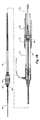
ここで図面の図1から図5をより詳しく見てみると、この実施形態のハンドル及びステントグラフト配備装置組立体10は、ハンドル部分12と、ステントグラフト送達部分14と、を含んでいることが分かるであろう。送達部分14は、ステントグラフトを脈管構造へ送達し脈管構造内で解放するために、セルジンガー法により患者の脈管構造内に配備されるように配設されており、ハンドル部分12は、患者の体外に留められ、ステントグラフトを送達及び解放するべく医師により操縦される。
Looking more closely at FIGS. 1-5 of the drawings, it can be seen that the handle and stent graft
送達部分14は、ノーズコーン拡張器16と、バイオネット型継手22を用いてハンドル部分12へ係合されているシースハブ20から延びるシース18と、を含んでいる。ステントグラフトは、ノーズコーン拡張器16の遠位側の隣接する領域24に、シース18の下に保持されている。装置は、ガイドワイヤカテーテル56に通されたガイドワイヤ(図示せず)越しに患者の中へ導入される。シースハブ20は、送達装置のプッシャー38を通過させる止血シール20a(図4A参照)を有している。
The
ハンドル組立体12は、近位把持部32を含む解放ハンドル30と、回転子要素36が取り付けられている固定ハンドル34と、を備えている。固定ハンドル34は実質的に円筒状で、その外表面に把持模様が付いている。固定ハンドル34は、固定ハンドル半部34aと34bを解放ハンドル30の周りに一体に嵌め合わせて構成されている。回転子要素36も実質的に円筒状で、その外表面に把持模様が付いている。
The
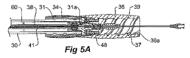
図5Aから最もよく分かる様に、回転子要素36は実質的に円筒状であり、その外表面に把持模様が付いている。回転子要素36は、その内部円筒面36aに第1スクリューねじと第2スクリューねじを含んでいる。第1スクリューねじ37は、内表面36aからの突出部を備えている。1つの実施形態では、第1スクリューねじ37は、32mmのピッチを有していて、1mmの深さと3mmの幅を有する突出部を備えている。第2スクリューねじ39は、内表面36aにカット又は溝として形成されている。1つの実施形態では、スクリューねじ39は、32mmのピッチを有していて、2mmの深さと2mmの幅を有する螺旋溝を備えている。この様に第1スクリューねじ37と第2スクリューねじ39は、同じピッチを備え、同心である。
As best seen in FIG. 5A, the
図2に詳しく示されている様に、解放ハンドル30は、半円筒状の解放ハンドル半部30aと30bをステントグラフト送達装置のためのプッシャー38の周りに一体に嵌め合わせて形成されている。解放ハンドル30は、その外表面に、その遠位端30cに向かって、スクリューねじ31が形成されている。解放ハンドル30の外表面のスクリューねじ31は、回転子要素36の内表面の第1スクリューねじ37と係合する。よって、1つの実施形態では、スクリューねじ31は、32mmのピッチを有していて、1mmの深さと3mmの幅を有する溝を備えている。
As shown in detail in FIG. 2, the release handle 30 is formed by fitting semi-cylindrical release handle
プッシャー38は、プッシャーハブ40を含み、ハブ40からはピン42が対角線上をそれぞれの方向に延びており、それらピン42は、図1から最もよく分かる様に、解放ハンドル30に沿って長手方向に延びているスロット44を貫いて延び、固定ハンドル半部34a及び34bの開口46へ係合している。プッシャーハブ40は、更に、ハブ40の円筒部分50に沿って滑動する解放クランプ48を含んでいる。解放クランプ48は、解放ハンドル30のスロット44を通って対角方向に延び、回転子要素36内の第2スクリューねじ39へ係合するピン52を含んでいる。第2スクリューねじ39は図5Aから最もよく分かる。
The
送達装置の領域24に保持されているステントグラフト64(図4参照)の各端から解放ワイヤ又はトリガーワイヤ33(図5D及び5E参照)が延びている。解放ワイヤ又はトリガーワイヤ33は、プッシャー38のルーメン41及びプッシャーハブ40内の止血シールを通過し、解放クランプ48に固定されている。解放ワイヤの機能は、図5Aから図5Eに関連してより詳細に論じる。
A release or trigger wire 33 (see FIGS. 5D and 5E) extends from each end of the stent graft 64 (see FIG. 4) held in the
送達装置は、ガイドワイヤカテーテル56と、当該ガイドワイヤカテーテル56の遠位端のシリンジハブ58と、を含んでいる。ガイドワイヤカテーテル56は、プッシャーハブ40とプッシャー38内のルーメン41を通ってノーズコーン拡張器16に至り、該ノーズコーン拡張器16を通って延びている。ステントグラフト64は、ノーズコーン拡張器16の遠位側に隣接してガイドワイヤカテーテル56の周りに同心円状に保持されている。
The delivery device includes a
解放ハンドルは、それぞれ、実質的に半円筒状であって、一体に接合されているときは管状本体を形成し、内部にはそれらの長さに沿った選択位置に段状肩部60が配置されて含まれている。段状肩部60は、図5Aから図5Eに関連して論じてゆくが、ステントグラフトのためのトリガーワイヤ又は解放ワイヤの解放を始動させる時期を判定するのに使用されている。
Each release handle is substantially semi-cylindrical and forms a tubular body when joined together, with stepped
図3は、送達装置の組み立て後のハンドル部分の破断図を示している。とりわけ、解放ハンドル30のスロット44が解放ハンドルの両側に在ることと、段状肩部60の位置とが見てとれる。これは、段状肩部60が解放クランプに係合する前に、解放ハンドルを固定ハンドル及び回転子要素の中を通して或る一定の量だけ進める必要のあることを意味している。プッシャーハブ40及び当該プッシャーハブ40側のピン42と解放クランプ48側のピン52が見え易いように、回転子要素36は図3から省略されている。
FIG. 3 shows a cutaway view of the handle portion after assembly of the delivery device. In particular, the
図4A及び図4Bは、図1に示されている本発明の実施形態の装置の長手方向断面図を示しており、送達前と装置作動時の或る段階での装置をそれぞれ示している。 4A and 4B show longitudinal cross-sectional views of the device of the embodiment of the invention shown in FIG. 1, showing the device before delivery and at some stage during device operation, respectively.
図4Aでは、解放ハンドル30のスクリューねじ31の遠位端31aが、回転子要素36の内部円筒面36aの第1スクリューねじ37にちょうど係合しているところである。
In FIG. 4A, the
図4Bに示されている段階では、固定ハンドル34及び回転子要素36が把持され、回転子要素36を回転させることで解放ハンドル30側のスクリューねじ31が回転子要素の内部円筒面36aの第1スクリューねじ37に沿って動かされることにより、解放ハンドル30が固定ハンドル34の中を通って動かされたところである。プッシャー38とプッシャーハブ40は、それらがピン42(図3)を使用して固定ハンドル34に係合されているので基本的に安定に保持されていて、解放ハンドル30が引き戻されることにより、シース18がノーズコーン拡張器16から遠位方向に後退し、ステントグラフト64を部分的に露出させる。この段階で、ステントグラフト64の近位端の露出しているステント66は、依然としてノーズコーン拡張器16の遠位端68の解放仕掛けに係合されており、ステントグラフトの大凡2つの覆われた状態のステントが露出されている。以下に論じてゆくが、肩部60の位置が、肩部60が解放クランプ48に当接係合する前の後退量を定めている。更に、この段階では、解放ハンドルには肩部が係合していないので、解放ハンドルから延びるピン52は、回転子要素36の内部円筒面36aの第2スクリューねじ39へまだ係合されていない。
In the stage shown in FIG. 4B, the fixed
ステントグラフトの近位端の導入器への保持方法は、PCT公報WO2003/101518「人工器官配備装置のためのトリガーワイヤシステム」に開示されている。この特徴並びにPCT公報WO2003/101518に開示されている他の特徴は、本発明と共に使用できるものであり、PCT公報WO2003/101518の開示を本明細書に援用する。 A method for holding the proximal end of the stent graft to the introducer is disclosed in PCT publication WO2003 / 101518 “Trigger wire system for prosthesis deployment devices”. This feature, as well as other features disclosed in PCT publication WO2003 / 101518, can be used with the present invention, the disclosure of PCT publication WO2003 / 101518 is incorporated herein.
図5Aから図5Eは、本発明の配備組立体を使用してステントグラフトを配備する場合の様々な段階を示している。これらの図面のそれぞれには、組立体のハンドル部分の固定ハンドルと回転子要素の詳細が示されている。 FIGS. 5A-5E illustrate the various stages of deploying a stent graft using the deployment assembly of the present invention. In each of these drawings, details of the fixed handle and rotor element of the handle portion of the assembly are shown.
図5Aでは、解放ハンドルは、組立体のハンドル部分の固定ハンドル及び回転子要素の中でその初期位置に在る。 In FIG. 5A, the release handle is in its initial position within the fixed handle and rotor element of the handle portion of the assembly.
この段階では、ステントグラフト64(図4A参照)は、シースハブ20まで延びているシース18により収縮状態で保持されている。ステントグラフトは、更に、少なくともその近位端が解放ワイヤ又はトリガーワイヤ(図示せず)により送達装置に保持されており、当該ワイヤは、プッシャー38のルーメン41及びプッシャーハブ40を通り次にプッシャーハブ40内のダクトを通って解放クランプ48まで延びて、解放クランプ48に締結されている。ステントグラフトの遠位端の保持及び解放についても類似の解放ワイヤシステム又はトリガーワイヤシステムを設けることができ、その場合、トリガーワイヤは、プッシャー38のルーメン41及びプッシャーハブ40を通り次にプッシャーハブ40内のダクトを通って解放クランプ48まで遡って延び、同様に解放クランプ48に締結されることになろう。
At this stage, the stent graft 64 (see FIG. 4A) is held in a contracted state by the
以下に論じてゆくが、解放クランプ48がプッシャーハブ40に対して動かされることで、トリガーワイヤがステントグラフト64との係合から後退し、それによりステントグラフトが解放されることになる。ステントグラフト64の近位端は、ステンドグラフトの少なくとも2つのステントが露出され展開できるようになった後に解放されるのが望ましく、ひいては、回転子要素36の第2スクリューねじ39は、段状肩部60が解放クランプ48に当接係合して解放クランプ48のピン52を第2スクリューねじと係合させてゆくことになって初めて当該解放クランプ48の当該ピン52に係合するように配設されているのが望ましい。更に、ステントグラフト64の遠位端64bを保持するトリガーワイヤが存在する場合、当該トリガーワイヤは、ステントグラフトが以下に図7に示されている様に一杯まで露出されて初めて解放されるのが望ましい。これを実現するため、トリガーワイヤは、ステントグラフトとのその遠位端の係合位置を裕に越えて延びるようにかなり長くされている。このことは、解放クランプ48が、回転子要素36から解放された後に後退を続け、段状肩部60との係合により遠位方向に動かされてゆく際、ステントグラフトの遠位端64b用のトリガーワイヤは、シース18がステントグラフト64から完全に退避させられるまで係合を解かれないことを意味する。
As discussed below, movement of the
固定ハンドル34と回転子要素36はどちらも、解放ハンドル30の円筒状本体が遠位方向に動かされる際に当該本体を通過させることのできる寸法であり、プッシャーハブ40と解放クランプ48は、解放ハンドル30の円筒状本体に周囲を通過させることのできる寸法である。段状肩部60と解放クランプ48は、段状肩部がプッシャーハブ40の周囲を通過してゆく間に段状肩部が解放クランプ48に当接係合する寸法である。
Both the fixed
解放ハンドル30が途中まで後退したところを図5Bに示している。これは、回転子要素36を固定ハンドル34に対して回転させて、スクリューねじ31及びひいては回転子要素36の第1スクリューねじ37と係合している解放ハンドル30を、回転子要素の中を通して推進させることにより実現される。この段階では、プッシャーハブ40と解放クランプ48は、固定ハンドル34と回転子要素36に対する各々の位置が、それらへのピン42及び52それぞれの係合により保持されている。ステントグラフト64の近位方向に延びる露出しているステント66は、シース18の後退により露出され、ステントグラフトの最近位端も露出されているが、ステントグラフトの近位端がその自己展開式ステント(図4B参照)の作用下に展開し始めることができる段階には至っていない。
FIG. 5B shows the release handle 30 retracted partway. This causes the
図5Cに示されている様に、回転子要素36を継続して回転させてゆくと、解放ハンドル30が、ひいてはシース18が同様に、固定ハンドル34及び回転子要素36に対して更に後退し、その結果ステントグラフト64がより多く露出され、段状肩部60が上述の様に解放クランプ48に当接係合したところである。この段階は図4Bにも示されている。ステントグラフトはその自己展開式ステントの作用下に途中まで展開したところである。医師は、この段階で、脈管構造内のステントグラフトの位置を再検討し、近位方向又は遠位方向或いは回転方向へ調節が必要であればそれを行うことができる。この目的のために、ステントグラフトは放射線不透過性マーカー(図示せず)を含んでいてもよい。
As shown in FIG. 5C, as the
ステントグラフトが正しく位置付けられたところで、次に回転子要素36を、図5Dに示されている様に固定ハンドル34に対して更に回転させることができる。これにより、解放クランプ48は遠位方向に動かされることになり、というのも、解放クランプのピン52が第2スクリューねじ39との係合に入るからであり、これはピンがスクリューねじ39の遠位端から出てゆくまで続く。これにより、トリガーワイヤ33は、近位保持から退避し、その結果、露出しているステント66が解放され、自己展開式ステントとして展開し、ステントが配備されている脈管構造の壁に当接係合してゆく。
Once the stent graft is correctly positioned, the
図5Eに示されている様に、ピン52が第2スクリューねじ39から係合解除され、スクリューねじ31が第1スクリューねじ37から係合解除されたとき、解放ハンドルを手で固定ハンドルに対して遠位方向に動かすことによって、シース18をステントグラフト64から外して完全に退避させることができる。ステントグラフトの遠位端を解放するトリガーワイヤが存在している場合は、この段階で、該ワイヤをステントグラフトとの係合から撤退させる。
When the
次いで、ハンドル及び配備装置組立体全体を患者から抜去することもできるし、或いは、バイオネット接続のところで分離することによりシースハブ20を解放ハンドル把持部32から切り離し、シースはシースを通しての更なる作業に備えて患者の中に残留させ、ハンドル、プッシャー、ガイドワイヤカテーテル、及びノーズコーン拡張器は、シースを通して回収されてもよい。
The entire handle and deployment device assembly can then be removed from the patient, or the
基本的に、図1から図5に示されている実施形態は、TTPの行為により特徴付けられている。即ち、シースを後退させるべく捻る(Twist)、トリガーワイヤを撤退させるべく捻る(Twist)、そしてシースの完全撤退を完遂するべく引く(Pull)。 Basically, the embodiment shown in FIGS. 1 to 5 is characterized by the act of TTP. That is, the sheath is twisted to retract (Twist), the trigger wire is twisted (Twist), and the sheath is completely retracted (Pull).
図6及び図7は、本発明の或る代わりの実施形態を示している。この実施形態では、先の実施形態に対応する要素は同じ参照番号を有している。 6 and 7 illustrate an alternative embodiment of the present invention. In this embodiment, elements corresponding to the previous embodiment have the same reference numbers.
この実施形態のハンドル及びステントグラフト配備装置組立体10は、ハンドル部分12と、ステントグラフト送達部分14と、を含んでいる。送達部分14は、ステントグラフトを脈管構造へ送達し脈管構造内で解放するセルジンガー法により患者の脈管構造内に配備されるように配設されており、ハンドル部分12は、患者の体外に留められ、ステントグラフトを送達及び解放するべく医師により操縦されることになる。
The handle and stent graft
送達部分14は、ノーズコーン拡張器16と、バイオネット型継手22を用いてハンドル部分12へ係合されているシースハブ20から延びるシース18と、を含んでいる。ステントグラフトは、ノーズコーン拡張器16の遠位側の隣接する領域24に、シース18の下に保持されている。装置は、ガイドワイヤカテーテル56に通されたガイドワイヤ(図示せず)越しに患者の中へ導入される。シースハブ20は、送達装置のプッシャー38を通過させる止血シール(図示せず)を有している。
The
ハンドル組立体12は、近位把持部32を含む解放ハンドル30と、回転子要素36が取り付けられている固定ハンドル34と、を備えている。固定ハンドル34は実質的に円筒状で、その外表面に把持模様が付いている。固定ハンドル34は、固定ハンドル半部34aと34bを解放ハンドル30の周りに一体に嵌め合わせて構成されている。回転子要素36も実質的に円筒状で、その外表面に把持模様が付いている。回転子要素36は、その内表面に単独の第1スクリューねじを有している。
The
この実施形態では、解放ハンドルの外表面のスクリューねじ31は、実質的に解放ハンドルの全長さに亘って延び、回転子要素の内表面のスクリューねじに係合している。回転子要素36を回転させると、シースのプッシャーに対する後退が開始され、ついには解放クランプ48が段状肩部60と係合する。この段階で、シースと解放クランプは、両者同時に遠位方向に動かされる。回転子要素を固定ハンドルに対して回転させ続けると、シース18が後退し続け、図7に示されている様に解放ハンドルが固定ハンドルに対して遠位方向へ動くことにより、ついにはステントグラフト64から外れて完全に退避する。解放クランプ48には継続して段状肩部60が係合しているので、遠位方向に更に遠くへ運ばれる。
In this embodiment, the
基本的に、図6及び図7に示されている実施形態は、Tの行為により特徴付けられている。即ち、捻る(Twist)ことで、シースを後退させ、トリガーワイヤを撤退させ、そしてシースを完全に撤退させることが、1つの滑らかで流れる様な動作として起こる。グラフトの近位端が解放される間は、シースは後退を止めない。 Basically, the embodiment shown in FIGS. 6 and 7 is characterized by the act of T. That is, twisting (Twist) retracts the sheath, retracts the trigger wire, and retracts the sheath completely as one smooth and flowing action. The sheath does not stop retracting while the proximal end of the graft is released.
図8、図8A、図8B、及び図8Cは、本発明による配備装置の或る代わりの実施形態の斜視図並びに当該実施形態の特定の部分の断面図を示している。この実施形態では、先の実施形態に対応する要素は同じ参照番号を有している。図8Bは、図8Aに示されている断面に対し90度回転させた断面であることに留意されたい。言い換えれば、図8Aは垂直平面の長手方向部分断面を示しており、図8Bは水平平面の長手方向部分断面を示している。図8Cは、図8に示されている実施形態の解放クランプの斜視図を示している。 8, 8A, 8B and 8C show a perspective view of an alternative embodiment of a deployment device according to the present invention and a cross-sectional view of certain parts of the embodiment. In this embodiment, elements corresponding to the previous embodiment have the same reference numbers. Note that FIG. 8B is a section rotated 90 degrees relative to the section shown in FIG. 8A. In other words, FIG. 8A shows a longitudinal partial section of a vertical plane, and FIG. 8B shows a longitudinal partial section of a horizontal plane. FIG. 8C shows a perspective view of the release clamp of the embodiment shown in FIG.
この実施形態のハンドル及びステントグラフト配備装置組立体70は、ハンドル部分12と、ステントグラフト送達部分14と、を含んでいる。送達部分14は、ステントグラフトを脈管構造へ送達し脈管構造内で解放するために、セルジンガー法により患者の脈管構造内に配備されるように配設されており、ハンドル部分12は、患者の体外に留められ、ステントグラフトを送達及び解放するべく医師により操縦されることになる。
The handle and stent graft
送達部分14は、ノーズコーン拡張器16と、バイオネット型継手22を用いてハンドル部分12へ係合されているシースハブ20から延びるシース18と、を含んでいる。ステントグラフトは、ノーズコーン拡張器16の遠位側の隣接する領域24に、シース18の下に保持されている。装置は、ガイドワイヤカテーテル56に通されたガイドワイヤ(図示せず)越しに患者の中へ導入される。シースハブ20は、送達装置のプッシャー38を通過させる止血シールを有している。
The
ハンドル組立体12は、近位把持部32を含む解放ハンドル30と、回転子要素36が取り付けられている固定ハンドル34と、を備えている。固定ハンドル34は実質的に円筒状で、その外表面に把持模様が付いている。回転子要素36も実質的に円筒状で、その外表面に把持模様が付いている。
The
この実施形態では、解放ハンドルの外表面のスクリューねじ31は、実質的に解放ハンドルの全長さに亘って延びており、よってスクリューねじ31は、図8Aに示されている様に、回転子要素36内で短いスクリューねじ72を係合させ続ける。回転子要素36を固定ハンドルに対して回転させ続けると、シース18が後退し続け、図7に示されている様に解放ハンドルが固定ハンドルに対して遠位方向へ動くことにより、ついにはステントグラフト64から外れて完全に退避する。
In this embodiment, the
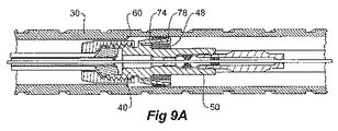
この実施形態では、解放クランプ48は、図8Bに示されている様に、ばねクリップ仕掛け73により、解放可能にプッシャーハブ40に保持されている。ばねクリップ仕掛け73の作動は、図9Aから図9Dに詳細に示されている。図9Aから図9Dには、分かり易くするために装置の一部しか示していない。
In this embodiment, the
解放クランプ48は、長手方向に動けるようにプッシャーハブ40の円筒部分50へ搭載されているが、プッシャーハブの遠位側に隣接して一対のばねクリップ74により保持されており、当該ばねクリップは、プッシャーハブと一体であってプッシャーハブから遠位方向に延びていて、ばねクリップ側の掛かり78が解放クランプ48側の当接部80に係合している状態で解放クランプ48の陥凹76の中へ受けられている。
The
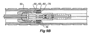
解放クランプをばねクリップとの係合から解くには、解放ハンドル30の内表面の肩部60がばねクリップ外表面82と係合し(図9B)、掛かり78を当接部80との係合から外す(図9C参照)。すると肩部60は直接に解放クランプ48と係合し、解放ハンドルが継続して動かされると、解放クランプがプッシャーハブ40の円筒部分50に沿って遠位方向に動かされる(図9C参照)。
To release the release clamp from engagement with the spring clip, the
解放ハンドル30の内表面の肩部60は、解放ハンドルが固定ハンドルに対して動かされている間、肩部が解放クランプ48に係合してそれを遠位方向に動かし、それにより、解放クランプに締結されているトリガーワイヤを引いてステントグラフトを送達装置70から解放させるように、配置されている。
The
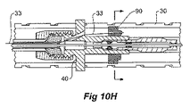
図10Aから図10Iは、或る代わりの解放クランプ保持システムの様々な詳細図とその動作段階を示している。この実施形態では、先の実施形態に対応している要素は同じ参照番号を有している。 10A-10I show various details of an alternative release clamp retention system and its operational stages. In this embodiment, elements corresponding to the previous embodiment have the same reference numbers.
図10Hは、図10A、図10C、及び図10Eに示されている断面に対し90度回転させた断面であることに留意されたい。言い換えれば、図10Hは垂直平面の長手方向部分断面を示しており、図10A、図10C、及び図10Eは水平平面の長手方向部分断面を示している。 Note that FIG. 10H is a section rotated 90 degrees relative to the sections shown in FIGS. 10A, 10C, and 10E. In other words, FIG. 10H shows a longitudinal partial section of a vertical plane, and FIGS. 10A, 10C, and 10E show a longitudinal partial section of a horizontal plane.
この実施形態では、解放クランプ90は、プッシャーハブ40の円筒部分50に対して、球戻り止めシステムにより保持されている。解放クランプ90は、球94を受け入れている一対の半径方向の孔92を有している。半径方向の孔は、それぞれ、球94が半径方向の孔92を完通できないようにするために内向肩部93を有している。図10A及び10Bに示されている位置では、解放クランプ90は、それぞれの球94がプッシャーハブ40の円筒部分50の陥凹96に受けられていることにより、プッシャーハブ40の円筒部分50と係合している。球94は、解放ハンドルの内表面のレール98が解放クランプ90の溝100へ係合し、球をプッシャーハブ40の円筒部分50の陥凹96へ係合させた状態に保持していることにより、陥凹96から脱出することを妨げられている。
In this embodiment, the
図10C及び10Dに示されている様に、滑動中のハンドルがレール98の陥凹102の在る位置まで動くと、球が陥凹102へ入ってゆき、プッシャーハブ40の円筒部分50の陥凹96へ係合した状態でなくなる。解放ハンドル30を継続して動かしてゆくことで球が運ばれて陥凹102へ係合し、陥凹96との係合が解かれるので、解放クランプ90は図10E及び図10Fに示されている様に、プッシャーハブ40の円筒部分50に沿って動けるようになる。これにより、上述のステントグラフトの部分の保持に使用されているトリガーワイヤが解放される。図10Hも参照されたし。
As shown in FIGS. 10C and 10D, when the sliding handle moves to the position where the recess 102 of the
図10Gは、解放クランプの斜視図を示している。この図から、溝100と半径方向の孔92は、ガイド突起部104の平面に直交する平面に在ることが分かるであろう。
FIG. 10G shows a perspective view of the release clamp. From this figure, it can be seen that the
図10H及び図10Iは、図10A、図10C、及び図10Eに示されている図に直交する平面での送達装置の一部分の長手方向断面図を示している。解放クランプ90は、プッシャーハブ40の円筒部分50に沿って動かされていることが示されている。トリガーワイヤ30は、解放クランプ90を通され、背面の106に締結されている。図10Hに示されている様に、トリガーワイヤ33は、解放クランプ90がプッシャーハブ40に対して動かされたことにより撤退している。
10H and 10I show longitudinal cross-sectional views of a portion of the delivery device in a plane orthogonal to the views shown in FIGS. 10A, 10C, and 10E. The
代わりの実施形態では、スクリューねじ部分は、解放ハンドルの近位部分及び遠位部分に設けられ、中間部分には設けられていない。代わりに、要求される機能性を発揮し易くするために、スクリューねじの何らかの組合せが、部分的又は全体的に、解放ハンドルの長さに沿って設けられていてもよい。 In an alternative embodiment, screw screw portions are provided in the proximal and distal portions of the release handle and not in the intermediate portion. Alternatively, some combination of screw threads may be provided along the length of the release handle, in part or in whole, to facilitate the required functionality.
その様な実施形態では、第1スクリューねじと第2スクリューねじが存在している。解放ハンドルの第1スクリューねじは、解放ハンドルの遠位端から近位方向に2区間に延在し、つまりは、解放ハンドルの遠位端から第1ねじ区間、次に第1ねじのない部分、そして次に第1ねじの第2ねじ区間が、選択された長さに亘って延在している。回転子要素の内表面の第2スクリューねじは、双子のねじを有しており、つまりは、一方は第1ねじに係合し、もう一方には解放クランプのピンが上述と同じ方式で係合する。 In such an embodiment, there are a first screw screw and a second screw screw. The first screw screw of the release handle extends in two sections proximally from the distal end of the release handle, i.e., the first screw section from the distal end of the release handle and then the first unthreaded part. And then the second threaded section of the first thread extends over a selected length. The second screw screw on the inner surface of the rotor element has a twin screw, ie one engages the first screw and the other engages the release clamp pin in the same manner as described above. Match.
第2スクリューねじが第1スクリューねじと係合してゆくことで、解放ハンドルを動かしシースを後退させる。回転子要素の対のねじのうちの第1のねじが解放ハンドルの第1ねじ区間から係合解除される直前に、解放クランプのピンが、第1のねじの重なり部を利用して、解放ハンドル内の第1の段状肩部によって回転子要素内の対のねじのうちの第2のねじへ係合される。ひとたび解放クランプのピンが第2のねじへ係合され、第1のねじが(第1ねじ区間と第2ねじ区間の間の空間部分で)係合解除されたら、解放ハンドル及びひいてはシースは静止状態に留まり、その間に解放クランプは対のねじのうちの第2のねじと共に後ろに引かれて、トリガーワイヤを解放する。次に、解放クランプのピンが回転子の第2のねじの端に来る直前に、解放クランプは、第2のねじの重なり部分を利用して、解放ハンドルの第2の段状肩部へ働き掛ける。解放クランプは、解放ハンドルを押すので、解放ハンドルの第1ねじの第2ねじ区間が回転子の第1のねじと係合することになる。回転子の第1のねじが解放ハンドルの第2ねじ区間と係合し、解放クランプのピンが回転子の第2のねじから係合解除されると、解放ハンドルは、回転子が回されることにより後退を継続する。これにより、トリガーワイヤが更に後退し、ついには、シースがグラフトを完全に露出させた直後にグラフトの遠位端が解放される。 When the second screw screw is engaged with the first screw screw, the release handle is moved to retract the sheath. Immediately before the first screw of the rotor element pair of screws is disengaged from the first screw section of the release handle, the release clamp pin releases using the overlap of the first screw. A first stepped shoulder in the handle engages a second screw of the pair of screws in the rotor element. Once the release clamp pin is engaged with the second screw and the first screw is disengaged (in the space between the first and second screw sections), the release handle and thus the sheath is stationary. It stays in the meantime, while the release clamp is pulled back with the second of the pair of screws to release the trigger wire. Next, just before the release clamp pin comes to the end of the second screw of the rotor, the release clamp uses the overlapping portion of the second screw to act on the second shoulder of the release handle. . The release clamp pushes the release handle so that the second thread section of the first screw of the release handle engages the first screw of the rotor. When the first screw of the rotor engages the second screw section of the release handle and the release clamp pin is disengaged from the second screw of the rotor, the release handle is rotated by the rotor. Continue to retreat. This further retracts the trigger wire and eventually releases the distal end of the graft immediately after the sheath fully exposes the graft.
この実施形態は、TTT様式と呼称される。即ち、シースを後退させるべく回す(Turn)、トリガーワイヤを退避させるべく回す(Turn)、そしてシースの完全退避を完遂するべく回す(Turn)。 This embodiment is referred to as the TTT format. That is, the sheath is rotated to retract (Turn), the trigger wire is rotated to retract (Turn), and the sheath is fully retracted (Turn).
図11は、本発明による配備装置のこの代わりの実施形態の斜視図を示している。この実施形態では、先の実施形態に対応する要素は同じ参照番号を有している。 FIG. 11 shows a perspective view of this alternative embodiment of a deployment device according to the present invention. In this embodiment, elements corresponding to the previous embodiment have the same reference numbers.
この実施形態のハンドル及びステントグラフト配備装置組立体10は、ハンドル部分12と、ステントグラフト送達部分14と、を含んでいる。送達部分14は、ステントグラフトを脈管構造へ送達し脈管構造内で解放するために、セルジンガー法により患者の脈管構造内に配備されるように配設されており、ハンドル部分12は、患者の体外に留められ、ステントグラフトを送達及び解放するべく医師により操縦されることになる。
The handle and stent graft
送達部分14は、ノーズコーン拡張器16と、バイオネット型継手22を用いてハンドル部分12へ係合されているシースハブ20から延びるシース18と、を含んでいる。ステントグラフトは、ノーズコーン拡張器16の遠位側の隣接する領域24に、シース18の下に保持されている。装置は、ガイドワイヤカテーテル56に通されたガイドワイヤ(図示せず)越しに患者の中へ導入される。シースハブ20は、送達装置のプッシャー38を通過させる止血シール(図示せず)を有している。
The
ハンドル組立体12は、近位把持部32を含む解放ハンドル30と、回転子要素36が取り付けられている固定ハンドル34と、を備えている。固定ハンドル34は実質的に円筒状で、その外表面に把持模様が付いている。固定ハンドル34は、固定ハンドル半部34aと34bを解放ハンドル30の周りに一体に嵌め合わせて構成されている。回転子要素36も実質的に円筒状で、その外表面に把持模様が付いている。回転子要素36は、その内面に単独の第1スクリューねじを有している。
The
この実施形態では、解放ハンドルの外表面のスクリューねじ31は、2つの区間に延在している。つまりは、解放ハンドルの遠位端から第1ねじ区間31a、次に第1ねじのない部分30a、そして次に第1ねじの第2ねじ区間31bが、選択された長さに亘って延在している。他の点では、構造は図6に関連して論じたものと同じであり、装置の作動は以上に論じている。
In this embodiment, the
本明細書全体を通して、本発明の範囲に関しては様々な示唆を与えてきたが、本発明は、これらの何れか1つに限定されるのではなく、これらの2つ又はそれ以上を一体に組み合わせたものに存することもあろう。実施例は、説明のみを目的に与えられたものであり、限定のためではない。 Throughout this specification, various suggestions have been given regarding the scope of the present invention, but the present invention is not limited to any one of these, and the two or more of these are combined together. There may be things that exist. The examples are given for illustrative purposes only and are not limiting.
本明細書及び以下に続く特許請求の範囲全体を通して、文脈上他の意味に解すべき場合を除き、「備える」及び「含む」並びに「備えている」や「含んでいる」の様な派生語は、言及されている或る完全体又は完全体の群の包含を含意するものではあるが、但しそれ以外の完全体又は完全体の群の排除を含意するものではないことを理解しておきたい。 Throughout this specification and the claims that follow, unless the context requires otherwise, derivatives such as “comprise” and “include” and “include” and “include” It should be understood that this does not imply the inclusion of any complete or complete group mentioned, but does not imply the exclusion of any other complete or complete group. I want.
2 ハンドル及びステントグラフト配備装置組立体の端(近位端)
4 近位方向を示す矢印
6 ハンドル及びステントグラフト配備装置組立体の端(遠位端)
8 遠位方向を示す矢印
10 ハンドル及びステントグラフト配備装置組立体
12 ハンドル部分
14 ステントグラフト送達部分
16 ノーズコーン拡張器
18 シース
20 シースハブ
20a 止血シール
22 バイオネット型継手
24 ステントグラフトが保持されている領域
30 解放ハンドル
30a、30b 解放ハンドル半部
30c 解放ハンドルの遠位端
31 解放ハンドルのスクリューねじ
31a スクリューねじ31の遠位端
32 近位把持部
33 解放ワイヤ又はトリガーワイヤ
34 固定ハンドル
34a、34b 固定ハンドル半部
36 回転子要素
36a 回転子要素の内部円筒面
37 内部円筒面の第1スクリューねじ
38 プッシャー
39 内部円筒面の第2スクリューねじ
40 プッシャーハブ
41 プッシャーのルーメン
42 プッシャーハブのピン
44 解放ハンドルのスロット
46 固定ハンドル半部の開口
48 解放クランプ
50 プッシャーハブの円筒部分
52 解放クランプのピン
56 ガイドワイヤカテーテル
58 シリンジハブ
60 解放ハンドルの段状肩部
64 ステントグラフト
64b ステントグラフトの遠位端
66 露出しているステント
68 ノーズコーン拡張器の遠位端
70 ハンドル及びステントグラフト配備装置組立体
72 回転子要素の短いスクリューねじ
73 ばねクリップ仕掛け
74 ばねクリップ
76 解放クランプの陥凹
78 ばねクリップ側の掛かり
80 解放クランプ側の当接部
82 ばねクリップ外表面
90 解放クランプ
92 解放クランプの半径方向の孔
93 半径方向の孔の内向肩部
94 球
96 プッシャーハブ円筒部分の陥凹
98 解放ハンドル内表面のレール
100 解放クランプの溝
102 レールの陥凹
104 解放クランプのガイド突起部
106 解放クランプ背面のトリガーワイヤ締結場所
2 End of handle and stent graft deployment device assembly (proximal end)
4 Arrow indicating proximal direction 6 End of handle and stent graft deployment device assembly (distal end)
8 Arrow indicating distal direction 10 Handle and stent graft deployment device assembly 12 Handle portion 14 Stent graft delivery portion 16 Nose cone dilator 18 Sheath 20 Sheath hub 20a Hemostatic seal 22 Bionette joint 24 Region holding stent graft 30 Release handle 30a, 30b Release handle half 30c Release handle distal end 31 Release handle screw screw 31a Screw screw 31 distal end 32 Proximal gripper 33 Release wire or trigger wire 34 Fixed handle 34a, 34b Fixed handle half 36 Rotor element 36a Inner cylindrical surface of rotor element 37 First screw screw 38 of inner cylindrical surface 38 Pusher 39 Second screw screw of inner cylindrical surface 40 Pusher hub 41 Lumen 42 of pusher Pusher hub pin 44 Release handle slot 46 Fixed handle half opening 48 Release clamp 50 Pusher hub cylindrical portion 52 Release clamp pin 56 Guide wire catheter 58 Syringe hub 60 Release handle stepped shoulder 64 Stent graft 64b Stent graft distal Distal end 66 Exposed stent 68 Distal end of nose cone dilator 70 Handle and stent graft deployment device assembly 72 Short screw screw of rotor element 73 Spring clip mechanism 74 Spring clip 76 Relief clamp recess 78 Spring clip side Hook 80 Release clamp side abutment 82 Spring clip outer surface 90 Release clamp 92 Release clamp radial hole 93 Radial hole inward shoulder 94 Ball 96 Pusher hub cylindrical part depression 98 of the groove 102 rail recess 104 relief clamp rail 100 release clamp release handle inner surface guide protrusion 106 releases the clamp back trigger wires fastening location
Claims (14)
前記ハンドル組立体は、固定ハンドルと該固定ハンドルに対して可動とされた解放ハンドルとを含み、前記固定ハンドルは使用者により把持及び保持される固定部分と回転させられる回転部分を備え、前記固定ハンドルの前記回転部分と前記解放ハンドルとは協働する第1スクリューねじを備えており、前記解放ハンドルを前記固定ハンドルの前記回転部分に対して回転させると前記固定ハンドルと前記解放ハンドルとの間に長手方向の相対移動が引き起こされるようになっており、
前記配備装置は、前記ステントグラフトが搭載されているプッシャー組立体と、前記プッシャー組立体にある前記ステントグラフトを覆い該ステントグラフトを該プッシャー組立体上で圧縮状態に保持するシースと、を含んでおり、前記シースは前記プッシャー組立体に対して相対的に可動とされ、前記プッシャー組立体は前記固定ハンドルに接続され前記シースは前記解放ハンドルに接続されており、
前記解放ハンドルを前記固定ハンドルに対して相対的に回転させることによって前記解放ハンドルを後退させると、前記シースが前記プッシャー組立体上にある前記ステントグラフトから少なくとも部分的に後退するようにされ、
前記固定ハンドルの前記固定部分が前記プッシャー組立体に係合され、前記固定ハンドルの前記回転部分が前記プッシャー組立体の解放クランプに係合され、該解放クランプは前記プッシャー組立体の長手方向で変位可能とされ、当該プッシャー組立体から前記ステントグラフトを解放するためのトリガーワイヤを有し、前記固定ハンドルの前記回転部の回転により前記解放クランプを動かし、前記トリガーワイヤを引っ張って前記ステントグラフトを前記プッシャー組立体から解放するようにされている、脈管内導入器。 An intravascular introducer comprising a combination of a handle assembly, a stent-graft deployment device, and a stent-graft retained on the stent-graft deployment device,
The handle assembly includes a fixed handle and a release handle movable with respect to the fixed handle. The fixed handle includes a fixed portion that is gripped and held by a user and a rotating portion that is rotated. The rotating portion of the handle and the release handle include a cooperating first screw screw, and when the release handle is rotated relative to the rotating portion of the fixed handle, between the fixed handle and the release handle. Causing relative movement in the longitudinal direction,
The deployment device includes a pusher assembly on which the stent graft is mounted, and a sheath that covers the stent graft in the pusher assembly and holds the stent graft in a compressed state on the pusher assembly, A sheath is movable relative to the pusher assembly, the pusher assembly is connected to the fixed handle, and the sheath is connected to the release handle;
Retracting the release handle by rotating the release handle relative to the fixed handle causes the sheath to retract at least partially from the stent graft on the pusher assembly;
The fixed portion of the fixed handle is engaged with the pusher assembly, the rotating portion of the fixed handle is engaged with a release clamp of the pusher assembly, and the release clamp is displaced in the longitudinal direction of the pusher assembly. is possible, has a trigger wire for releasing the stent graft from the pusher assembly to move the release clamped by rotation of the rotating portion of the fixed handle, the said stent graft by pulling the trigger wires An intravascular introducer adapted to be released from the pusher assembly.
The first screw screw of the release handle first has a first screw section from the distal end of the release handle, then has an unthreaded portion, and then has a second screw section. Extending over a length and extending in two sections from the distal end of the release handle, the second screw screw on the inner surface of the rotor portion comprises a pair of screws One screw engages the first screw screw and the other screw engages a pin of the release clamp so that the first screw screw moves the release handle to retract the sheath. And the pin of the release clamp utilizes the overlap of the first screw immediately before the first screw of the rotor portion is disengaged from the first screw section of the release handle. The first step shoulder Engaged with a second screw of the rotor portion, once the pin of the release clamp is engaged with the second screw, the first screw being in the first screw section and the second screw section. When disengaged in the space between the release handle and thus the sheath remains stationary, while the release clamp is pulled back with the second screw to release the trigger wire; The intravascular introducer according to claim 1, wherein a second threaded section of the first screw thread of the release handle engages the first thread of the rotor portion.
Applications Claiming Priority (3)
| Application Number | Priority Date | Filing Date | Title |
|---|---|---|---|
| US27939909P | 2009-10-20 | 2009-10-20 | |
| US61/279,399 | 2009-10-20 | ||
| PCT/US2010/052635 WO2011049808A1 (en) | 2009-10-20 | 2010-10-14 | Rotational controlled deployment device |
Publications (3)
| Publication Number | Publication Date |
|---|---|
| JP2013508080A JP2013508080A (en) | 2013-03-07 |
| JP2013508080A5 JP2013508080A5 (en) | 2013-08-29 |
| JP5699340B2 true JP5699340B2 (en) | 2015-04-08 |
Family
ID=43567575
Family Applications (1)
| Application Number | Title | Priority Date | Filing Date |
|---|---|---|---|
| JP2012535249A Active JP5699340B2 (en) | 2009-10-20 | 2010-10-14 | Rotation control type deployment device |
Country Status (5)
| Country | Link |
|---|---|
| US (1) | US9060895B2 (en) |
| EP (1) | EP2490629B1 (en) |
| JP (1) | JP5699340B2 (en) |
| AU (1) | AU2010308380B2 (en) |
| WO (1) | WO2011049808A1 (en) |
Families Citing this family (52)
| Publication number | Priority date | Publication date | Assignee | Title |
|---|---|---|---|---|
| JP5134729B2 (en) | 2008-07-01 | 2013-01-30 | エンドロジックス、インク | Catheter system |
| US8858613B2 (en) | 2010-09-20 | 2014-10-14 | Altura Medical, Inc. | Stent graft delivery systems and associated methods |
| EP2559403B1 (en) | 2009-12-01 | 2016-05-04 | Altura Medical, Inc. | Modular endograft devices |
| EP2428189A1 (en) | 2010-09-10 | 2012-03-14 | Symetis Sa | Catheter delivery system for stent valve |
| US9414915B2 (en) * | 2010-09-24 | 2016-08-16 | Symetis Sa | Stent valve, delivery apparatus and method therefor |
| CN105232195B (en) | 2011-03-01 | 2018-06-08 | 恩朵罗杰克斯股份有限公司 | Delivery catheter system |
| AU2011202175B1 (en) * | 2011-05-11 | 2011-07-28 | Cook Medical Technologies Llc | Rotation operated delivery device |
| US9144494B2 (en) * | 2011-05-12 | 2015-09-29 | Medtronic, Inc. | Delivery catheter system with micro and macro movement control |
| WO2013025549A1 (en) | 2011-08-12 | 2013-02-21 | W. L. Gore & Associates, Inc. | Devices and methods for approximating the cross-sectional profile of vasculature having branches |
| US10213329B2 (en) | 2011-08-12 | 2019-02-26 | W. L. Gore & Associates, Inc. | Evertable sheath devices, systems, and methods |
| EP2775931B1 (en) | 2011-11-08 | 2018-03-07 | Boston Scientific Scimed, Inc. | Handle assembly for a left atrial appendage occlusion device |
| US9782282B2 (en) | 2011-11-14 | 2017-10-10 | W. L. Gore & Associates, Inc. | External steerable fiber for use in endoluminal deployment of expandable devices |
| US9877858B2 (en) | 2011-11-14 | 2018-01-30 | W. L. Gore & Associates, Inc. | External steerable fiber for use in endoluminal deployment of expandable devices |
| US9687371B2 (en) | 2012-02-14 | 2017-06-27 | W. L. Gore & Associates, Inc. | Endoprosthesis having aligned legs for ease of cannulation |
| US9375308B2 (en) | 2012-03-13 | 2016-06-28 | W. L. Gore & Associates, Inc. | External steerable fiber for use in endoluminal deployment of expandable devices |
| US8920485B2 (en) * | 2012-04-13 | 2014-12-30 | Medtronic Vascular, Inc. | Stent-graft delivery system having a rotatable single shaft tip capture mechanism |
| EP2846742A1 (en) | 2012-05-10 | 2015-03-18 | Biotronik AG | Unit and device having a unit for positioning a prosthetic component |
| WO2014026173A1 (en) | 2012-08-10 | 2014-02-13 | Cragg Andrew H | Stent delivery systems and associated methods |
| US9308349B2 (en) * | 2013-02-08 | 2016-04-12 | Vention Medical Advanced Components, Inc. | Universal catheter handle |
| US9763819B1 (en) | 2013-03-05 | 2017-09-19 | W. L. Gore & Associates, Inc. | Tapered sleeve |
| US9987155B1 (en) | 2013-03-07 | 2018-06-05 | W. L. Gore & Associates, Inc. | Implantable medical devices and related delivery systems |
| US9737426B2 (en) | 2013-03-15 | 2017-08-22 | Altura Medical, Inc. | Endograft device delivery systems and associated methods |
| US9827121B2 (en) | 2013-03-15 | 2017-11-28 | Cook Medical Technologies Llc | Quick release deployment handle for medical devices |
| CN103356316B (en) * | 2013-07-25 | 2015-07-01 | 苏州英络医疗器械有限公司 | High shrinkage intravascular stent delivery system |
| US9999751B2 (en) * | 2013-09-06 | 2018-06-19 | Catheter Precision, Inc. | Adjustable nose cone for a catheter positioning system |
| US9907641B2 (en) | 2014-01-10 | 2018-03-06 | W. L. Gore & Associates, Inc. | Implantable intraluminal device |
| USD806244S1 (en) | 2014-01-31 | 2017-12-26 | Nordson Corporation | Catheter actuation handle |
| US10966850B2 (en) | 2014-03-06 | 2021-04-06 | W. L. Gore & Associates, Inc. | Implantable medical device constraint and deployment apparatus |
| US9974675B2 (en) | 2014-04-04 | 2018-05-22 | W. L. Gore & Associates, Inc. | Delivery and deployment systems for bifurcated stent grafts |
| US9833346B2 (en) | 2014-04-04 | 2017-12-05 | W. L. Gore & Associates, Inc. | Deployment handle for a medical device deployment system |
| US10226368B2 (en) * | 2014-04-23 | 2019-03-12 | Medtronic Vascular, Inc. | Delivery system for a retractable outer sheath |
| US10478324B2 (en) | 2014-08-12 | 2019-11-19 | W. L. Gore & Associates, Inc. | Handle for medical device deployment |
| EP3040058A1 (en) | 2014-12-29 | 2016-07-06 | Cook Medical Technologies LLC | Deployment handle for a delivery device with mechanism for quick release of a prosthesis and re-sheathing of device tip |
| US10159587B2 (en) * | 2015-01-16 | 2018-12-25 | Boston Scientific Scimed, Inc. | Medical device delivery system with force reduction member |
| US10058441B2 (en) * | 2015-05-20 | 2018-08-28 | Cook Medical Technologies Llc | Deployment handle for a pre-loaded iliac prosthesis delivery device |
| US11129737B2 (en) | 2015-06-30 | 2021-09-28 | Endologix Llc | Locking assembly for coupling guidewire to delivery system |
| US10172733B2 (en) * | 2015-09-01 | 2019-01-08 | Cook Medical Technologies Llc | Modular handle for a prosthesis delivery device |
| US10034785B1 (en) | 2015-10-13 | 2018-07-31 | W. L. Gore & Associates, Inc. | Single site access aortic aneurysm repair method |
| US10321996B2 (en) * | 2015-11-11 | 2019-06-18 | Edwards Lifesciences Corporation | Prosthetic valve delivery apparatus having clutch mechanism |
| US10610393B2 (en) | 2016-03-24 | 2020-04-07 | Cook Medical Technologies Llc | Wire retention and release mechanisms |
| US11266418B2 (en) | 2016-08-05 | 2022-03-08 | W. L. Gore & Associates, Inc. | Integrated medical device constraining lumen |
| WO2018039000A1 (en) | 2016-08-24 | 2018-03-01 | W. L. Gore & Associates, Inc. | Sleeves for expandable medical devices |
| RU2652732C1 (en) * | 2016-12-30 | 2018-04-28 | Общество с ограниченной ответственностью "СЕВЕН САНС" | Device and method for safe positioning of coronary stent in coronary arteries |
| RU2669994C2 (en) * | 2016-12-30 | 2018-10-17 | Общество с ограниченной ответственностью "СЕВЕН САНС" | Device and method for safe positioning of coronary stent in coronary arteries |
| JP6985401B2 (en) | 2017-02-14 | 2021-12-22 | ダブリュ.エル.ゴア アンド アソシエイツ, インコーポレイティドW.L. Gore & Associates, Incorporated | Implantable medical device delivery system and method |
| RU2661092C9 (en) * | 2017-04-12 | 2018-10-22 | Общество с ограниченной ответственностью "СЕВЕН САНС" | Device and method for safe positioning of coronary stent in coronary arteries |
| ES2960532T3 (en) | 2017-10-11 | 2024-03-05 | Gore & Ass | Implantable medical device restraint and deployment apparatus |
| RU2686956C1 (en) * | 2017-12-29 | 2019-05-06 | Общество с ограниченной ответственностью "СЕВЕН САНС" | Device and method for safe positioning of coronary stent in coronary arteries |
| CN110786973B (en) * | 2018-08-03 | 2022-11-08 | 先健科技(深圳)有限公司 | Assembly, conveyor and system for controlling release of an implantation instrument |
| WO2022101960A1 (en) * | 2020-11-10 | 2022-05-19 | 日本ライフライン株式会社 | Stent delivery catheter device |
| WO2022240680A1 (en) * | 2021-05-11 | 2022-11-17 | Bolton Medical, Inc. | Aortic prosthesis delivery device and method of use |
| WO2023278495A2 (en) | 2021-06-28 | 2023-01-05 | Inquis Medical, Inc. | Apparatuses and methods for controlling removal of obstructive material |
Family Cites Families (7)
| Publication number | Priority date | Publication date | Assignee | Title |
|---|---|---|---|---|
| US5906619A (en) * | 1997-07-24 | 1999-05-25 | Medtronic, Inc. | Disposable delivery device for endoluminal prostheses |
| CA2486390C (en) | 2002-05-29 | 2011-01-04 | William A. Cook Australia Pty. Ltd. | Trigger wire system for a prosthesis deployment device |
| US7264632B2 (en) * | 2002-06-07 | 2007-09-04 | Medtronic Vascular, Inc. | Controlled deployment delivery system |
| US7780717B2 (en) | 2006-04-27 | 2010-08-24 | Med Institute, Inc. | Rotary handle for controlled sequential deployment device |
| US20080262590A1 (en) * | 2007-04-19 | 2008-10-23 | Medtronic Vascular, Inc. | Delivery System for Stent-Graft |
| US8475514B2 (en) | 2007-08-13 | 2013-07-02 | Cook Medical Technologies Llc | Deployment device |
| JP5846505B2 (en) * | 2010-05-14 | 2016-01-20 | メドトロニック ヴァスキュラー インコーポレイテッド | Prosthesis delivery system catheter handle |
-
2010
- 2010-10-14 US US13/502,940 patent/US9060895B2/en active Active
- 2010-10-14 WO PCT/US2010/052635 patent/WO2011049808A1/en active Application Filing
- 2010-10-14 AU AU2010308380A patent/AU2010308380B2/en active Active
- 2010-10-14 JP JP2012535249A patent/JP5699340B2/en active Active
- 2010-10-14 EP EP10774047.4A patent/EP2490629B1/en active Active
Also Published As
| Publication number | Publication date |
|---|---|
| AU2010308380A1 (en) | 2012-05-17 |
| EP2490629B1 (en) | 2019-05-22 |
| US20120221091A1 (en) | 2012-08-30 |
| EP2490629A1 (en) | 2012-08-29 |
| WO2011049808A1 (en) | 2011-04-28 |
| JP2013508080A (en) | 2013-03-07 |
| US9060895B2 (en) | 2015-06-23 |
| AU2010308380B2 (en) | 2013-04-04 |
Similar Documents
| Publication | Publication Date | Title |
|---|---|---|
| JP5699340B2 (en) | Rotation control type deployment device | |
| US11096811B2 (en) | Deployment handle for an introducer | |
| JP5364933B2 (en) | Placement device | |
| US8709061B2 (en) | Pre-loaded multiport delivery device | |
| US20230165698A1 (en) | Modular handle comprising a trigger wire actuation mechanism for a prosthesis delivery device | |
| EP3017794A1 (en) | Deployment handle for a prosthesis delivery device | |
| US20230088094A1 (en) | Modular handle for a prosthesis delivery device |
Legal Events
| Date | Code | Title | Description |
|---|---|---|---|
| A521 | Request for written amendment filed |
Free format text: JAPANESE INTERMEDIATE CODE: A523 Effective date: 20130703 |
|
| A621 | Written request for application examination |
Free format text: JAPANESE INTERMEDIATE CODE: A621 Effective date: 20130703 |
|
| A521 | Request for written amendment filed |
Free format text: JAPANESE INTERMEDIATE CODE: A523 Effective date: 20130704 |
|
| A977 | Report on retrieval |
Free format text: JAPANESE INTERMEDIATE CODE: A971007 Effective date: 20140502 |
|
| A131 | Notification of reasons for refusal |
Free format text: JAPANESE INTERMEDIATE CODE: A131 Effective date: 20140513 |
|
| A521 | Request for written amendment filed |
Free format text: JAPANESE INTERMEDIATE CODE: A523 Effective date: 20140702 |
|
| TRDD | Decision of grant or rejection written | ||
| A01 | Written decision to grant a patent or to grant a registration (utility model) |
Free format text: JAPANESE INTERMEDIATE CODE: A01 Effective date: 20141224 |
|
| A711 | Notification of change in applicant |
Free format text: JAPANESE INTERMEDIATE CODE: A711 Effective date: 20150116 |
|
| A61 | First payment of annual fees (during grant procedure) |
Free format text: JAPANESE INTERMEDIATE CODE: A61 Effective date: 20150119 |
|
| A521 | Request for written amendment filed |
Free format text: JAPANESE INTERMEDIATE CODE: A821 Effective date: 20150116 |
|
| R150 | Certificate of patent or registration of utility model |
Ref document number: 5699340 Country of ref document: JP Free format text: JAPANESE INTERMEDIATE CODE: R150 |
|
| R250 | Receipt of annual fees |
Free format text: JAPANESE INTERMEDIATE CODE: R250 |
|
| R250 | Receipt of annual fees |
Free format text: JAPANESE INTERMEDIATE CODE: R250 |
|
| R250 | Receipt of annual fees |
Free format text: JAPANESE INTERMEDIATE CODE: R250 |
|
| R250 | Receipt of annual fees |
Free format text: JAPANESE INTERMEDIATE CODE: R250 |
|
| R250 | Receipt of annual fees |
Free format text: JAPANESE INTERMEDIATE CODE: R250 |
|
| R250 | Receipt of annual fees |
Free format text: JAPANESE INTERMEDIATE CODE: R250 |
|
| R250 | Receipt of annual fees |
Free format text: JAPANESE INTERMEDIATE CODE: R250 |