JP5697667B2 - Outer shell sector for winged rings for aircraft turbomachine stators, including damping shims - Google Patents
Outer shell sector for winged rings for aircraft turbomachine stators, including damping shims Download PDFInfo
- Publication number
- JP5697667B2 JP5697667B2 JP2012522172A JP2012522172A JP5697667B2 JP 5697667 B2 JP5697667 B2 JP 5697667B2 JP 2012522172 A JP2012522172 A JP 2012522172A JP 2012522172 A JP2012522172 A JP 2012522172A JP 5697667 B2 JP5697667 B2 JP 5697667B2
- Authority
- JP
- Japan
- Prior art keywords
- sector
- shim
- basic
- sectors
- outer shell
- Prior art date
- Legal status (The legal status is an assumption and is not a legal conclusion. Google has not performed a legal analysis and makes no representation as to the accuracy of the status listed.)
- Expired - Fee Related
Links
Images


Classifications
-
- F—MECHANICAL ENGINEERING; LIGHTING; HEATING; WEAPONS; BLASTING
- F04—POSITIVE - DISPLACEMENT MACHINES FOR LIQUIDS; PUMPS FOR LIQUIDS OR ELASTIC FLUIDS
- F04D—NON-POSITIVE-DISPLACEMENT PUMPS
- F04D29/00—Details, component parts, or accessories
- F04D29/40—Casings; Connections of working fluid
- F04D29/52—Casings; Connections of working fluid for axial pumps
- F04D29/54—Fluid-guiding means, e.g. diffusers
- F04D29/541—Specially adapted for elastic fluid pumps
- F04D29/542—Bladed diffusers
-
- F—MECHANICAL ENGINEERING; LIGHTING; HEATING; WEAPONS; BLASTING
- F01—MACHINES OR ENGINES IN GENERAL; ENGINE PLANTS IN GENERAL; STEAM ENGINES
- F01D—NON-POSITIVE DISPLACEMENT MACHINES OR ENGINES, e.g. STEAM TURBINES
- F01D11/00—Preventing or minimising internal leakage of working-fluid, e.g. between stages
- F01D11/001—Preventing or minimising internal leakage of working-fluid, e.g. between stages for sealing space between stator blade and rotor
-
- F—MECHANICAL ENGINEERING; LIGHTING; HEATING; WEAPONS; BLASTING
- F01—MACHINES OR ENGINES IN GENERAL; ENGINE PLANTS IN GENERAL; STEAM ENGINES
- F01D—NON-POSITIVE DISPLACEMENT MACHINES OR ENGINES, e.g. STEAM TURBINES
- F01D25/00—Component parts, details, or accessories, not provided for in, or of interest apart from, other groups
- F01D25/04—Antivibration arrangements
- F01D25/06—Antivibration arrangements for preventing blade vibration
-
- F—MECHANICAL ENGINEERING; LIGHTING; HEATING; WEAPONS; BLASTING
- F01—MACHINES OR ENGINES IN GENERAL; ENGINE PLANTS IN GENERAL; STEAM ENGINES
- F01D—NON-POSITIVE DISPLACEMENT MACHINES OR ENGINES, e.g. STEAM TURBINES
- F01D25/00—Component parts, details, or accessories, not provided for in, or of interest apart from, other groups
- F01D25/24—Casings; Casing parts, e.g. diaphragms, casing fastenings
- F01D25/246—Fastening of diaphragms or stator-rings
-
- F—MECHANICAL ENGINEERING; LIGHTING; HEATING; WEAPONS; BLASTING
- F04—POSITIVE - DISPLACEMENT MACHINES FOR LIQUIDS; PUMPS FOR LIQUIDS OR ELASTIC FLUIDS
- F04D—NON-POSITIVE-DISPLACEMENT PUMPS
- F04D29/00—Details, component parts, or accessories
- F04D29/60—Mounting; Assembling; Disassembling
- F04D29/64—Mounting; Assembling; Disassembling of axial pumps
- F04D29/644—Mounting; Assembling; Disassembling of axial pumps especially adapted for elastic fluid pumps
-
- F—MECHANICAL ENGINEERING; LIGHTING; HEATING; WEAPONS; BLASTING
- F04—POSITIVE - DISPLACEMENT MACHINES FOR LIQUIDS; PUMPS FOR LIQUIDS OR ELASTIC FLUIDS
- F04D—NON-POSITIVE-DISPLACEMENT PUMPS
- F04D29/00—Details, component parts, or accessories
- F04D29/66—Combating cavitation, whirls, noise, vibration or the like; Balancing
- F04D29/661—Combating cavitation, whirls, noise, vibration or the like; Balancing especially adapted for elastic fluid pumps
- F04D29/668—Combating cavitation, whirls, noise, vibration or the like; Balancing especially adapted for elastic fluid pumps damping or preventing mechanical vibrations
-
- F—MECHANICAL ENGINEERING; LIGHTING; HEATING; WEAPONS; BLASTING
- F01—MACHINES OR ENGINES IN GENERAL; ENGINE PLANTS IN GENERAL; STEAM ENGINES
- F01D—NON-POSITIVE DISPLACEMENT MACHINES OR ENGINES, e.g. STEAM TURBINES
- F01D9/00—Stators
- F01D9/02—Nozzles; Nozzle boxes; Stator blades; Guide conduits, e.g. individual nozzles
- F01D9/04—Nozzles; Nozzle boxes; Stator blades; Guide conduits, e.g. individual nozzles forming ring or sector
- F01D9/042—Nozzles; Nozzle boxes; Stator blades; Guide conduits, e.g. individual nozzles forming ring or sector fixing blades to stators
Description
本発明は、一般に、好ましくはターボジェットまたはターボプロップタイプの航空機ターボ機械に関する。 The present invention generally relates to aircraft turbomachines, preferably of the turbojet or turboprop type.
より具体的には、本発明は、この種のターボ機械の圧縮機またはタービンステータに、より正確には、複数のステータ翼と、翼を支持し、かつそれぞれ内側におよび外側にターボ機械を通過する一次流れを半径方向に画定するように設計される2つの同心シェルとを備える、翼付きリングセクタに関する。この種の翼付きリングは、通常、端と端をつないで配置されるいくつかのセクタを用いて作られ、通常、ガイドベーンまたはノズルとして圧縮機またはタービンに使用される。 More specifically, the present invention supports a compressor or turbine stator of this type of turbomachine, more precisely, supporting a plurality of stator blades and blades and passing through the turbomachine inward and outward respectively. And a winged ring sector comprising two concentric shells designed to radially define a primary flow. This type of winged ring is usually made with several sectors arranged end-to-end and is typically used in compressors or turbines as guide vanes or nozzles.
ターボ機械は、通常、連続して低圧圧縮機、高圧圧縮機、燃焼室、高圧タービン、および低圧タービンを備えている。圧縮機およびタービンは、円周方向の間隔を置いて可動翼のいくつかの列を備え、これらの列は、やはり円周方向の間隔を置いて固定翼の列によって分離される。現代のターボ機械では、高い動的応力が、ガイドベーンおよびノズルに加えられる。技術進歩により、等しいかまたはよりよい性能を得るために段の数の減少がもたらされ、その結果、それぞれの段により高い負荷が生じる。さらに、製造技術の変化により、部品の数の減少がもたらされており、それにより、部品の間の連結部の減衰効果が低減される。これは、特に、振動エネルギーの散逸の大きな源を排除するアブレイダブルカートリッジろう付け技術が使用される場合が該当する。 Turbomachines typically include a low pressure compressor, a high pressure compressor, a combustion chamber, a high pressure turbine, and a low pressure turbine in succession. The compressor and turbine comprise several rows of movable blades spaced circumferentially, and these rows are separated by rows of stationary blades, also spaced circumferentially. In modern turbomachinery, high dynamic stresses are applied to the guide vanes and nozzles. Technological advances result in a reduction in the number of stages in order to obtain equal or better performance, resulting in higher loads on each stage. Furthermore, changes in manufacturing technology have led to a reduction in the number of parts, thereby reducing the damping effect of the connection between the parts. This is especially true when an abradable cartridge brazing technique is used that eliminates a significant source of vibration energy dissipation.
仏国特許出願公開第2902843号明細書は、斜めまたは他の方向にスリットまたは半径方向カットを使用することによって、外側シェルセクタを、接線方向に沿って互いから一定の間隔で基本セクタに分断することによってこの振動問題を解決する手段を開示しており、各基本セクタは、翼付きリングセクタの単一の翼を支持する。さらに、ストリップの形の減衰インサートが、基本セクタの間に挿入される。動作原理は、構造体の動的挙動に剛性非線形性を導入することに基づいている。この非線形性は、システムの閾値振動レベルによって起動される。この振動活動により、翼の基本セクタと減衰インサートとの間に相対運動が生じる。この相対運動により、減衰インサートの接着の連続する損失と回復、およびその結果として、システムの局所的剛性の連続的変化が生じる。したがって、振動活動を引き起こすモード(複数可)は、関連する固有振動数の持続的な変化によって混乱させられる。システムの共振は、動的システムの状態の連続的変化のゆえに引き起こされ得ない。これにより、システムの振動振幅が低減される。 FR-A-2902843 divides the outer shell sectors into basic sectors at regular intervals from one another along the tangential direction by using slits or radial cuts in an oblique or other direction. Thus, each basic sector supports a single wing of a winged ring sector. In addition, a damping insert in the form of a strip is inserted between the basic sectors. The principle of operation is based on introducing stiffness nonlinearity into the dynamic behavior of the structure. This non-linearity is triggered by the threshold vibration level of the system. This oscillating activity causes relative movement between the basic sector of the wing and the damping insert. This relative motion results in a continuous loss and recovery of the damping insert adhesion and, as a result, a continuous change in the local stiffness of the system. Thus, the mode (s) that cause vibrational activity are confused by persistent changes in the associated natural frequency. System resonances cannot be caused due to continuous changes in the state of the dynamic system. This reduces the vibration amplitude of the system.
それにもかかわらず、たとえこの解決策が振動の低減に関して満足のいくものであっても、これは改善され得る。さらに、仏国特許出願公開第2902843号明細書に開示されているこの解決策では、減衰インサートは、空気力学的な流路と圧縮機の外側との間の圧力勾配の効果により基本セクタの摩擦面に接触して保持され、その結果、これらのインサートに半径方向内向きの力を加える。欠点は、この圧力勾配が、インサートを摩擦面と満足のいくように強制的に接触させるには十分ではあり得ないということである。この場合には、結果は、起こり得る空気流路の非漏出性の損失だけでなく、まず第1に制振性能の低下である。 Nevertheless, even if this solution is satisfactory with respect to vibration reduction, this can be improved. Furthermore, in this solution disclosed in French Patent Application No. 2902843, the damping insert has a basic sector friction due to the effect of the pressure gradient between the aerodynamic flow path and the outside of the compressor. It is held in contact with the surface, resulting in a radially inward force being applied to these inserts. The disadvantage is that this pressure gradient cannot be sufficient to force the insert into satisfactory contact with the friction surface. In this case, the result is not only a possible non-leakage loss of the air flow path, but first of all a reduction in damping performance.
この解決策のもつ他の欠点は、翼付きリングセクタの翼のうちの1つが過負荷になるということである。翼に加えられる空気力学的な力は、接線方向に間隔を置いて配置される基本セクタの中のセグメント化により、外側シェルセクタにおいて抵抗され得ない接線方向成分を含んでいる。したがって、これらの接線方向成分は、合成され、翼付きリングセクタの内側シェルセクタを通過してから、リングセクタに取り付けられる回転防止ストップ部に隣接して配置される翼を通過する。したがって、外側シェルセクタが接線方向に沿って静的な力を伝達することができないことにより、この翼は、非常に高い負荷が掛けられる。 Another disadvantage of this solution is that one of the blades of the winged ring sector is overloaded. The aerodynamic force applied to the wing includes a tangential component that cannot be resisted in the outer shell sector due to segmentation within the tangentially spaced basic sectors. Thus, these tangential components are combined and pass through the inner shell sector of the winged ring sector and then through the wings located adjacent to the anti-rotation stop attached to the ring sector. The wing is therefore subjected to a very high load by the inability of the outer shell sector to transmit a static force along the tangential direction.
したがって、本発明の目的は、先行技術による実施形態で生じる上述の問題を少なくとも部分的に克服することである。 The object of the present invention is therefore to at least partly overcome the above-mentioned problems arising in the prior art embodiments.
これを達成するための本発明の第1の目的は、航空機ターボ機械の圧縮機またはタービンステータに使用される翼付きリングセクタ用の外側シェルセクタを形成する組立体であり、前記外側シェルセクタが、第1に、前記組立体の接線方向に沿って互いから間隔を置いて複数の基本セクタを、および第2に、それらのうちのそれぞれが前記接線方向に沿って直接連続して配置される、これと関連する2つの基本セクタの間に挿入される制振シムを備える組立体である。 A first object of the present invention to achieve this is an assembly that forms an outer shell sector for a winged ring sector used in an aircraft turbomachine compressor or turbine stator, said outer shell sector comprising: Firstly, a plurality of basic sectors spaced from each other along the tangential direction of the assembly, and secondly, each of them being arranged directly in succession along the tangential direction An assembly comprising a damping shim inserted between two basic sectors associated therewith.
本発明によれば、各制振シムの輪郭は、基本セクタの輪郭とほぼ同じである。 According to the present invention, the contour of each damping shim is substantially the same as the contour of the basic sector.
シムの特定の輪郭のため、シムと基本セクタとの間の摩擦界面が大きく、それにより、減衰効果の改善になる。 Due to the specific contour of the shim, the friction interface between the shim and the basic sector is large, thereby improving the damping effect.
さらに、シムが基本セクタの摩擦面と接触することを余儀なくさせられることは、空気力学的な流路と圧縮機またはタービンの外側との間の圧力差から独立して、これらの要素の間の完全なシールとなり得る。このシールは、ほぼ接線方向に沿って基本セクタの摩擦面に力を加えるシムを有する構造によって得られる。摩擦面およびシムを互いに接触させる力が、基本セクタに対して、ステータ翼に加えられる空気力学的な力の接線方向成分を加えることによって強調されるので、このシールは動作時にさらに強化されることに留意されたい。 In addition, being forced to contact the friction surface of the basic sector, the shim is independent of the pressure difference between the aerodynamic flow path and the outside of the compressor or turbine, between these elements. It can be a perfect seal. This seal is obtained by a structure having a shim that applies a force to the friction surface of the basic sector substantially along the tangential direction. The seal is further strengthened in operation because the force that causes the friction surface and the shim to contact each other is emphasized by adding a tangential component of the aerodynamic force applied to the stator blades to the basic sector. Please note that.
翼に加えられる空気力学的な力の接線方向成分に関して、本発明の本質的な利点の1つは、外側シェルセクタが制振シムの特定の位置決めにより接線方向に沿って非常に大きく補強されるので、たとえこれがこの方向に沿ってセクタに分離されても、この成分は外側シェルセクタを形成する組立体を通過し得るということにあることに留意されたい。結果は、それによってほぼ一様に負荷を掛けられる翼について過負荷が全くないことである。 With regard to the tangential component of the aerodynamic force applied to the wing, one of the essential advantages of the present invention is that the outer shell sector is reinforced significantly along the tangential direction by specific positioning of the damping shim. Thus, it should be noted that even if this is separated into sectors along this direction, this component can pass through the assembly forming the outer shell sector. The result is that there is no overload for the wings that are loaded almost uniformly.
最後に、基本セクタの輪郭とほぼ同じ輪郭を採用することによって、空気流路とも呼ばれる一次環状流れの外側半径方向境界画定部が、互いから間隔を置いて基本セクタの間に完全に再現されることに留意されたい。 Finally, by adopting a contour that is approximately the same as the contour of the basic sector, the outer radial boundary delimiters of the primary annular flow, also called the air flow path, are perfectly reproduced between the basic sectors, spaced from each other. Please note that.
前記シムは、前記接線方向に沿って互いに向かい合い、かつ前記シムと関連する前記2つの基本セクタに設けられる2つの平行で平らな摩擦面と接触して当たっており、前記シムは、互いに平行な、かつ基本セクタの2つの対応する摩擦面と協働する2つの相補形の平らな摩擦面を有することが好ましい。摩擦面と相補形の摩擦面との間の平らな接触部分は、摩擦によって満足な振動の減衰を与える。また、直線状のスリット、換言すればその内側に対応するシムが後にはめ込まれる、決定された面にスリットを得るために、たとえば単一の切断動作によって、単一の機械加工操作時に同時に2つの摩擦面を作ることも可能である。これは、本発明による組立体を製造するのを非常に簡単にし、それにより、重要なコストおよび時間の節約になる。 The shims face each other along the tangential direction and are in contact with two parallel flat friction surfaces provided in the two basic sectors associated with the shim, the shims being parallel to each other And preferably have two complementary flat friction surfaces cooperating with two corresponding friction surfaces of the basic sector. The flat contact between the friction surface and the complementary friction surface provides satisfactory vibration damping due to friction. Also, in order to obtain a slit in the determined plane, in which a straight slit, in other words a corresponding shim inside it is fitted, is obtained simultaneously, for example by a single cutting operation, during a single machining operation. It is also possible to create a friction surface. This greatly simplifies the manufacture of the assembly according to the invention, thereby saving significant costs and time.
前記シムには、圧縮機またはタービンステータの然るべき位置にこれを保持するようにフックが設けられ、したがって、これらのフックは基本セクタに固定されるフックと同じ輪郭を有することが好ましい。 The shim is provided with hooks to hold it in place on the compressor or turbine stator, and therefore these hooks preferably have the same contour as the hooks fixed to the basic sector.
基本セクタは、前記制振シムで完全に塞がれる半径方向スリットによって互いから分離されることが好ましい。 The basic sectors are preferably separated from each other by radial slits that are completely closed by the damping shims.
前記制振シムは、前記組立体のほぼ軸方向または斜め方向に沿って延在することが好ましい。 It is preferable that the damping shim extends substantially along the axial direction or the oblique direction of the assembly.
この発明の他の目的は、上で説明したような外側シェルセクタを形成する組立体と、内側シェルセクタと、互いから接線方向の間隔を置いて、かつ外側シェルセクタを形成する組立体と内側シェルセクタとの間に挿入される複数の翼とを備える、航空機ターボ機械の圧縮機またはタービンステータに取り付けられるように設計される翼付きリングセクタに適用される。この場合には、各基本セクタは、本発明の範囲の外側に広がることなく、単一のステータ翼、または多分いくつかの翼を担持することになる。 Another object of the present invention is to provide an assembly for forming an outer shell sector as described above, an inner shell sector, an assembly tangentially spaced from each other, and forming an outer shell sector. Applies to a winged ring sector designed to be attached to a compressor or turbine stator of an aircraft turbomachine with a plurality of wings inserted between the shell sector. In this case, each basic sector will carry a single stator blade, or possibly several blades, without extending outside the scope of the present invention.
翼付きリングは、圧縮機のガイドベーンまたはタービンのノズルを形成することができる。 The bladed ring can form a guide vane for a compressor or a nozzle for a turbine.
さらに、リングセクタは、5°と60°との間の角度範囲にわたって延在することが好ましいが、翼付きリング全体を形成するように360°と同程度であり得る。 Further, the ring sector preferably extends over an angular range between 5 ° and 60 °, but can be as high as 360 ° to form the entire winged ring.
本発明の他の目的は、上で説明したような少なくとも1つの翼付きリングセクタを備えた圧縮機またはタービンステータを備える航空機ターボ機械である。 Another object of the invention is an aircraft turbomachine comprising a compressor or turbine stator with at least one winged ring sector as described above.
本発明の他の利点および特徴は、下で述べられる詳細な非限定的な説明で明らかになる。 Other advantages and features of the invention will become apparent in the detailed non-limiting description set forth below.
この説明は、添付の図面を参照して行われる。 This description is made with reference to the accompanying drawings.
まず第1に図1を参照して、図は、本発明が適用できる航空機ターボジェット100を示している。これは、上流から下流方向に沿って順に、低圧圧縮機2、高圧圧縮機4、環状燃焼室6、高圧タービン8、および低圧タービン10を備えている。
Referring first to FIG. 1, the figure shows an
図2は、高圧圧縮機4の一部を示している。知られている方法で、圧縮機は、ステータ翼の列14と、圧縮機の軸線12に平行な軸方向で交互するロータ翼の列16とを備える。軸線12の周りに円周方向に/接線方向に配置されるステータ翼18は、好ましくは円周方向22に沿ってセクタで構成される、翼付きリング20と称するステータの一部に含まれる。したがって、翼付きリングセクタ20を指す次に述べることでは、このセクタ20は、好ましくは5°と60°との間の角度範囲、場合によっては翼付きリング全体を形成するようにほぼ360°にわたって延在することが理解される。
FIG. 2 shows a part of the high-
したがって、タービンノズルまたは圧縮機ガイドベーンのすべてまたは一部を形成するセクタ20は、ターボ機械を通過する一次環状流れ26を半径方向に画定する内表面を形成する内側シェルセクタ24を備え、このシェルセクタ24は、ステータ翼18の固定された根元部を支持する。これらの翼18に加えて、セクタ20はまた、一次環状流れを半径方向に画定する外表面を形成する外側シェルセクタ28を形成し、かつ翼18の固定された頂部を支持する組立体を備える。
Thus, the
この点で、セクタ20はまた、回転ブレードを支持するロータ段16によって支持され、かつ当該セクタ20の下流側に配置されるシール装置31によって接触される環状シールトラックを形成する半径方向内側アブレイダブル被覆部29などの、シェルセクタ24に取り付けられる知られている追加要素を備えることに留意されたい。回転シール装置31は、知られているラビリンスまたはリップシール型のシール装置である。
In this regard, the
図3は、翼付きリングセクタ20を示している。説明した好ましい実施形態では、タービンノズルまたは圧縮機ガイドベーン全体は、複数のこれらのセクタ20を端と端をつないで配置することによって得られ、したがって、それぞれは、この翼付きリングの角度的または円周方向部分を形成する。角度セクタ20(その1つだけが、図3で見られ得る)は、それらを互いに連結する任意の剛体的かつ直接的な機械的リンクを持たないことが好ましく、それらの隣接する端部は、隙間有りまたは隙間無しで単に互いにそれぞれ向かい合わせに配置される。
FIG. 3 shows a
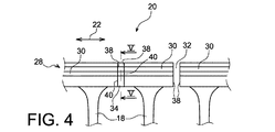
より具体的には、図3および図4を参照して、図は、内側リングセクタ24が単一の部品で作られ、セグメント化されないことを示している。他方では、外側シェルセクタ28を形成する組立体28は、真っ直ぐな半径方向のまたは僅かに斜めのスリット32によってセグメント化されて、接線方向22に沿って互いから間隔を置いて基本セクタ30になり、したがって、直接連続したセクタ30の間で隙間を作り出す。各スリット32は、2つの直接連続した翼18の間の中間直線に沿って作られ、それによって、各基本セクタ30は、単一の固定ステータ翼18を支持する。セクタ20の端部に配置される2つの基本セクタ30のうちの1つは、半径方向外側に突出する回転ストップ部33を支持し、それは、知られている方法で圧縮機ステータの他の部分と協働する。
More specifically, with reference to FIGS. 3 and 4, the figures show that the
また、組立体28は、直接連続した基本セクタ30の間にはめ込まれる制振シム34を備えている。
The
より正確には、各制振シム34は、接線方向22に沿って互いに向かい合う2つの平らな平行摩擦面38の間にはめ込まれ、シムと関連する2つの基本セクタの互いに向かい合う対応する接線方向端部に設置される。同様に、各シム34は、互いに平行な、かつまた平行でこれらが協働する2つの対応する平らな摩擦面38と接触する、2つの相補形の平らな摩擦面40を有する。
More precisely, each damping
したがって、摩擦面38の形状と相補形の形状を有する各シム34は、2つの直接連続する基本セクタ30の間に押し込まれる。
Thus, each
各対の2つの摩擦面38と摩擦面40の間の接触は、シム34がその2つの関連する基本セクタ30の間で適切な位置に配置されるとすぐに得られることが好ましい。したがって、シム34は、基本セクタの摩擦面38と接触してほぼ接線方向に方向付けられる力を加え、その結果、それらの相補形の平らな摩擦面40が生じる。これらの力は、基本セクタに対して、ステータ翼に加えられる空気力学的な力の接線方向成分を追加的に加えることによって、動作時に増加されることが有利である。
Contact between each pair of two friction surfaces 38 and 40 is preferably obtained as soon as the
図5に概略的に示されるように、本発明の特別な特徴の1つは、シム34の輪郭が基本セクタの輪郭とほぼ同じであり、この同じ輪郭が外側シェルセクタの輪郭に対応するということにある。この開示では、輪郭は、断面図が図5に示されているが、接線方向22に沿って見られる要素の全体的な形状を指している。
As schematically shown in FIG. 5, one particular feature of the present invention is that the contour of
このように、基本セクタ30と同様に、各シム34の下面46は、空気流路の外側半径方向境界画定部としての機能を果たす。したがって、シム34およびセクタ30に形成されるこれらの表面46の連続から成る空気流路の全体的環状境界画定表面は、連続した表面46の間にいかなる段もないので空気力学的な観点からほぼ連続的である。
Thus, like the
また、各シム34および各セクタ30は、圧縮機ステータのもう1つの部分に対して然るべき位置にこれを保持するフックを、より正確には、前方に突出する固定用フック48および後方に突出する固定用フック50を備えている。図2に示されるように、フック48およびフック50は、ステータのこの他の部分にセクタ20を固定するように、圧縮機ステータのもう1つの部分に設けられる対応する環状スリット52およびスリット54にはめ込まれる。
Each
スリット32を完全に塞ぐシム34は、文書仏国特許FR−A−2902843号明細書に開示されるシムについて上で説明した物理的原理に基づいて、摩擦面38と接触して摩擦によって制振機能を実行する。また、これらは、シール機能と、ステータ翼に加えられる空気力学的な力の接線方向成分が通過するようになっている機能とを実行する。より一般的にはこの点で、各シム34は、これが挿入される2つの基本セクタ30の間で接線方向力を伝達することができる。
The
基本セクタ30およびシム34に使用される材料の性質は、ほぼ同じ、好ましくは金属性であり、基本セクタ30ではなくてシムが優先的に摩耗するように選択される。
The nature of the materials used for the
また、厚さにやはり対応する、接線方向に沿った各シムの大きさと各基本セクタの大きさとの比は、0.5と1の間にあることに留意されたい。 It should also be noted that the ratio between the size of each shim along the tangential direction and the size of each basic sector, which also corresponds to the thickness, is between 0.5 and 1.
図6aから図6cは、翼付きリングセクタ20の製造のためのプロセスを概略的に示している。まず第1に図6aで見ることができるように、一体の組立体100が、内側シェルセクタ24、外側シェルセクタ28、およびステータ翼18を形成する鋳込みまたは機械加工によって作られる。次のステップは、簡単で費用のかからない機械加工によって、図6bに概略的に示されるように基本セクタ30を得るように、外側シェルセクタ28に真っ直ぐな半径方向スリット32を作ることである。たとえば、これらのスリット32は、単にセクタ28を切断することによって作られ得る。
FIGS. 6 a to 6 c schematically show a process for the manufacture of the
最後に、図6cは、それらの対応する穴の中に単にシムを摺動させることによって、制振シム34を、摩擦面を形成するスリット32の適切な位置に設置することから成る最終ステップを示している。
Finally, FIG. 6c shows the final step consisting of placing the damping
正確な摺動調整隙間は、2つの摩擦面38の間に単に力を強制することによって、このシムをそのスリットに保持しながら各シムをその関連するスリットに挿入することを比較的容易にするのに好まれることに留意されたい。 An accurate sliding adjustment gap makes it relatively easy to insert each shim into its associated slit while holding the shim in its slit by simply forcing a force between the two friction surfaces 38. Please note that it is preferred.
明らかに、当業者は、単に非限定的な例を用いて上で説明したような本発明のさまざまな改変を行うこともできる。 Obviously, those skilled in the art can make various modifications of the invention as described above, merely using non-limiting examples.
Claims (5)
外側シェルセクタ(28)を形成する組立体と、内側シェルセクタ(24)と、互いから接線方向の間隔を置いて、かつ外側シェルセクタを形成する組立体と内側シェルセクタとの間に挿入された複数の翼(18)とを備えており、前記翼が、外側シェルセクタを形成する組立体と内側シェルセクタとの各々に固定されており、外側シェルセクタ(28)を形成する前記組立体が、第1に、前記組立体の接線方向(22)に沿って互いから間隔を置いて複数の基本セクタ(30)を、第2に、各々がこれに関連する前記接線方向に沿って直接連続して配置された2つの基本セクタの間に挿入される、複数の制振シム(34)を備えており、
各制振シム(34)の輪郭が、基本セクタ(30)の輪郭とほぼ同じであり、
前記制振シム(34)が、前記組立体のほぼ斜め方向に沿って延在することを特徴とする、前記セクタ。 A winged ring sector (20) designed to be installed in a compressor stator of an aircraft turbomachine,
Inserted between the assembly forming the outer shell sector (28), the inner shell sector (24), tangentially spaced from each other and between the assembly forming the outer shell sector and the inner shell sector was provided with a plurality of the blades (18), said assembly the wing is fixed to each of the assembly and the inner shell sector to form the outer shell sector, to form the outer shell sector (28) but the first, a plurality of basic sectors (30) spaced from each other along the tangential direction (22) of the assembly, the second, directly along the tangential direction, each associated with it is successively inserted between the arranged two basic sectors, provided with a plurality of damping shims (34),
Contours of the damping shim (34) state, and are substantially the same as the contour of the base sector (30),
The vibration damping shim (34), characterized in that extending substantially along the oblique direction of the assembly, said sectors.
Applications Claiming Priority (3)
| Application Number | Priority Date | Filing Date | Title |
|---|---|---|---|
| FR0955439 | 2009-07-31 | ||
| FR0955439A FR2948736B1 (en) | 2009-07-31 | 2009-07-31 | EXTERNAL VIROLE SECTOR FOR AIRBORNE TURBOMACHINE AIRBORNE STATOR CROWN, COMPRISING SHOCK ABSORBING MOUNTS |
| PCT/EP2010/061037 WO2011012679A2 (en) | 2009-07-31 | 2010-07-29 | Outer shell sector for a bladed stator ring of an aircraft turbine engine, comprising vibration-damping blocks |
Publications (2)
| Publication Number | Publication Date |
|---|---|
| JP2013501181A JP2013501181A (en) | 2013-01-10 |
| JP5697667B2 true JP5697667B2 (en) | 2015-04-08 |
Family
ID=41800367
Family Applications (1)
| Application Number | Title | Priority Date | Filing Date |
|---|---|---|---|
| JP2012522172A Expired - Fee Related JP5697667B2 (en) | 2009-07-31 | 2010-07-29 | Outer shell sector for winged rings for aircraft turbomachine stators, including damping shims |
Country Status (9)
| Country | Link |
|---|---|
| US (1) | US20120128482A1 (en) |
| EP (1) | EP2459884B1 (en) |
| JP (1) | JP5697667B2 (en) |
| CN (1) | CN102472297A (en) |
| BR (1) | BR112012002304A2 (en) |
| CA (1) | CA2769217A1 (en) |
| FR (1) | FR2948736B1 (en) |
| RU (1) | RU2537997C2 (en) |
| WO (1) | WO2011012679A2 (en) |
Families Citing this family (16)
| Publication number | Priority date | Publication date | Assignee | Title |
|---|---|---|---|---|
| FR2971022B1 (en) | 2011-02-02 | 2013-01-04 | Snecma | COMPRESSOR RECTIFIER STAGE FOR A TURBOMACHINE |
| US9610644B2 (en) * | 2011-02-08 | 2017-04-04 | United Technologies Corporation | Mate face brazing for turbine components |
| US9546557B2 (en) * | 2012-06-29 | 2017-01-17 | General Electric Company | Nozzle, a nozzle hanger, and a ceramic to metal attachment system |
| US9334756B2 (en) | 2012-09-28 | 2016-05-10 | United Technologies Corporation | Liner and method of assembly |
| US10066548B2 (en) | 2013-03-15 | 2018-09-04 | United Technologies Corporation | Acoustic liner with varied properties |
| DE102013212252A1 (en) * | 2013-06-26 | 2014-12-31 | Siemens Aktiengesellschaft | Turbine and method of squeal detection |
| FR3008455B1 (en) * | 2013-07-09 | 2015-08-21 | Snecma | COMPRESSOR RECTIFIER HAVING GAME RETRIEVAL MEANS |
| CN104440153B (en) * | 2014-11-04 | 2017-06-06 | 中国南方航空工业(集团)有限公司 | Casing intra vane processes damping unit |
| FR3029242B1 (en) | 2014-11-28 | 2016-12-30 | Snecma | TURBOMACHINE TURBINE, COMPRISING INTERCROSSED PARTITIONS FOR AIR CIRCULATION IN DIRECTION OF THE LEAK EDGE |
| US10655482B2 (en) * | 2015-02-05 | 2020-05-19 | Rolls-Royce Corporation | Vane assemblies for gas turbine engines |
| JP6689117B2 (en) * | 2016-03-31 | 2020-04-28 | 三菱日立パワーシステムズ株式会社 | Stator blade ring and axial flow rotary machine equipped in the axial flow rotary machine |
| CN106988794B (en) * | 2017-06-02 | 2018-12-14 | 中国航发南方工业有限公司 | Stator sub-assembly clamping means and stator sub-assembly |
| CN107747563B (en) * | 2017-09-30 | 2020-04-10 | 中国航发沈阳发动机研究所 | Fan casing with damping |
| US11242762B2 (en) * | 2019-11-21 | 2022-02-08 | Raytheon Technologies Corporation | Vane with collar |
| FR3115819B1 (en) * | 2020-11-02 | 2023-04-14 | Safran Aircraft Engines | Aircraft turbomachine stator assembly, comprising an external structure formed of two annular sections surrounding a bladed stator crown |
| FR3119196B1 (en) * | 2021-01-27 | 2022-12-23 | Safran Aircraft Engines | Sectorized annular row of fixed vanes |
Family Cites Families (13)
| Publication number | Priority date | Publication date | Assignee | Title |
|---|---|---|---|---|
| US2661147A (en) * | 1949-01-19 | 1953-12-01 | Ingersoll Rand Co | Blower blade fastening device |
| SU453486A1 (en) * | 1973-04-11 | 1974-12-15 | DEVICE FOR DAMPING THE OSCILLATIONS OF WORK BLADDES OF AXIAL TURBO DUMPERS | |
| JPS5239807A (en) * | 1975-09-25 | 1977-03-28 | Mitsubishi Heavy Ind Ltd | Moving vane vibration controlling apparatus |
| US5201850A (en) * | 1991-02-15 | 1993-04-13 | General Electric Company | Rotor tip shroud damper including damper wires |
| DE4436731A1 (en) * | 1994-10-14 | 1996-04-18 | Abb Management Ag | compressor |
| FR2831615B1 (en) * | 2001-10-31 | 2004-01-02 | Snecma Moteurs | SECTORIZED FIXED RECTIFIER FOR A TURBOMACHINE COMPRESSOR |
| US6984108B2 (en) * | 2002-02-22 | 2006-01-10 | Drs Power Technology Inc. | Compressor stator vane |
| US6733237B2 (en) * | 2002-04-02 | 2004-05-11 | Watson Cogeneration Company | Method and apparatus for mounting stator blades in axial flow compressors |
| EP1510654A1 (en) * | 2003-08-25 | 2005-03-02 | Siemens Aktiengesellschaft | Unitary turbine blade array and method to produce the unitary turbine blade array. |
| US7104752B2 (en) * | 2004-10-28 | 2006-09-12 | Florida Turbine Technologies, Inc. | Braided wire damper for segmented stator/rotor and method |
| FR2902843A1 (en) * | 2006-06-23 | 2007-12-28 | Snecma Sa | COMPRESSOR RECTIFIER AREA OR TURBOMACHINE DISTRIBUTOR SECTOR |
| US7591634B2 (en) * | 2006-11-21 | 2009-09-22 | General Electric Company | Stator shim welding |
| US7806655B2 (en) * | 2007-02-27 | 2010-10-05 | General Electric Company | Method and apparatus for assembling blade shims |
-
2009
- 2009-07-31 FR FR0955439A patent/FR2948736B1/en active Active
-
2010
- 2010-07-29 CN CN2010800340319A patent/CN102472297A/en active Pending
- 2010-07-29 RU RU2012107522/06A patent/RU2537997C2/en not_active IP Right Cessation
- 2010-07-29 JP JP2012522172A patent/JP5697667B2/en not_active Expired - Fee Related
- 2010-07-29 US US13/386,496 patent/US20120128482A1/en not_active Abandoned
- 2010-07-29 CA CA2769217A patent/CA2769217A1/en not_active Abandoned
- 2010-07-29 WO PCT/EP2010/061037 patent/WO2011012679A2/en active Application Filing
- 2010-07-29 BR BR112012002304A patent/BR112012002304A2/en not_active IP Right Cessation
- 2010-07-29 EP EP10739591.5A patent/EP2459884B1/en active Active
Also Published As
| Publication number | Publication date |
|---|---|
| EP2459884B1 (en) | 2018-06-27 |
| BR112012002304A2 (en) | 2016-05-31 |
| CN102472297A (en) | 2012-05-23 |
| FR2948736A1 (en) | 2011-02-04 |
| WO2011012679A3 (en) | 2011-04-21 |
| JP2013501181A (en) | 2013-01-10 |
| CA2769217A1 (en) | 2011-02-03 |
| RU2537997C2 (en) | 2015-01-10 |
| RU2012107522A (en) | 2013-09-10 |
| FR2948736B1 (en) | 2011-09-23 |
| WO2011012679A2 (en) | 2011-02-03 |
| US20120128482A1 (en) | 2012-05-24 |
| EP2459884A2 (en) | 2012-06-06 |
Similar Documents
| Publication | Publication Date | Title |
|---|---|---|
| JP5697667B2 (en) | Outer shell sector for winged rings for aircraft turbomachine stators, including damping shims | |
| CA2749494C (en) | Resilient mounting apparatus for low-ductility turbine shroud | |
| US6884028B2 (en) | Turbomachinery blade retention system | |
| US8579580B2 (en) | Mounting apparatus for low-ductility turbine shroud | |
| CN107002690B (en) | Rotating assembly for a turbine engine comprising a self-supporting rotor casing | |
| US8727735B2 (en) | Rotor assembly and reversible turbine blade retainer therefor | |
| JP5427398B2 (en) | Turbomachined sectorized nozzle | |
| EP2568121B1 (en) | Stepped conical honeycomb seal carrier and corresponding annular seal | |
| EP3042043B1 (en) | Turbomachine bucket having angel wing seal for differently sized discouragers and related fitting method | |
| JP2007154890A (en) | Retrofit blade stator for turbo-engine | |
| US10184345B2 (en) | Cover plate assembly for a gas turbine engine | |
| JP2014514501A (en) | Sealing device for turbomachine turbine nozzle | |
| EP2615256B1 (en) | Spring "t" seal of a gas turbine | |
| JP2017082765A (en) | Turbine snap-in spring seal | |
| US20160258310A1 (en) | Seal arrangement | |
| US10871079B2 (en) | Turbine sealing assembly for turbomachinery | |
| US10844737B2 (en) | Additively manufactured module for a turbomachine | |
| US20170089210A1 (en) | Seal arrangement for compressor or turbine section of gas turbine engine | |
| US11156108B2 (en) | Multi-blade vane for a turbomachine rotor and rotor comprising same | |
| EP3284911B1 (en) | Gas turbine engine with a fan case wear liner | |
| US10655483B2 (en) | Run-up surface for the guide-vane shroud plate and the rotor-blade base plate |
Legal Events
| Date | Code | Title | Description |
|---|---|---|---|
| A621 | Written request for application examination |
Free format text: JAPANESE INTERMEDIATE CODE: A621 Effective date: 20130725 |
|
| A131 | Notification of reasons for refusal |
Free format text: JAPANESE INTERMEDIATE CODE: A131 Effective date: 20140428 |
|
| A977 | Report on retrieval |
Free format text: JAPANESE INTERMEDIATE CODE: A971007 Effective date: 20140430 |
|
| A521 | Written amendment |
Free format text: JAPANESE INTERMEDIATE CODE: A523 Effective date: 20140724 |
|
| TRDD | Decision of grant or rejection written | ||
| A01 | Written decision to grant a patent or to grant a registration (utility model) |
Free format text: JAPANESE INTERMEDIATE CODE: A01 Effective date: 20150127 |
|
| A61 | First payment of annual fees (during grant procedure) |
Free format text: JAPANESE INTERMEDIATE CODE: A61 Effective date: 20150210 |
|
| R150 | Certificate of patent or registration of utility model |
Ref document number: 5697667 Country of ref document: JP Free format text: JAPANESE INTERMEDIATE CODE: R150 |
|
| LAPS | Cancellation because of no payment of annual fees |