JP5693153B2 - Image processing apparatus and image processing method - Google Patents
Image processing apparatus and image processing method Download PDFInfo
- Publication number
- JP5693153B2 JP5693153B2 JP2010246762A JP2010246762A JP5693153B2 JP 5693153 B2 JP5693153 B2 JP 5693153B2 JP 2010246762 A JP2010246762 A JP 2010246762A JP 2010246762 A JP2010246762 A JP 2010246762A JP 5693153 B2 JP5693153 B2 JP 5693153B2
- Authority
- JP
- Japan
- Prior art keywords
- reflection characteristic
- image signal
- image
- correction amount
- acquiring
- Prior art date
- Legal status (The legal status is an assumption and is not a legal conclusion. Google has not performed a legal analysis and makes no representation as to the accuracy of the status listed.)
- Active
Links
Images


Description
本発明は、原稿からの複製の作成等に好適な画像処理装置及び画像処理方法等に関する。 The present invention relates to an image processing apparatus and an image processing method suitable for creating a copy from a document.
文字や画像等の情報を用紙やフィルム等シート状の記録媒体に記録を行う記録装置には様々な方式のものがある。その中で、記録媒体に記録剤(色材)を付着することで記録媒体上にテキストや画像を形成する方式が実用化されている。このような方式の代表例として、インクジェット記録装置、電子写真記録装置、昇華型熱転写記録装置等がある。近年、これらの記録装置の性能が向上し、モノクロ画像やテキストばかりでなく、カラー画像も記録されるようになってきた。しかしながら、これらの記録装置では、記録装置に入力される入力信号(例えば、R,G,B)が同じであっても、使用される記録媒体の種類が異なると再現される色が異なってしまうことが知られている。
上記課題を解決する技術として、記録媒体の種類に応じた色補正を行うことで所望の色再現を実現する技術が開示されている(特許文献1)。特に、異なる記録媒体間で再現される色をマッチングさせる技術は一般的によく知られている。
There are various types of recording apparatuses that record information such as characters and images on a sheet-like recording medium such as paper or film. Among them, a method of forming text and images on a recording medium by attaching a recording agent (coloring material) to the recording medium has been put into practical use. Typical examples of such a system include an ink jet recording apparatus, an electrophotographic recording apparatus, and a sublimation type thermal transfer recording apparatus. In recent years, the performance of these recording apparatuses has been improved, and not only monochrome images and text but also color images have been recorded. However, in these recording apparatuses, even if the input signals (for example, R, G, B) input to the recording apparatus are the same, the color to be reproduced differs depending on the type of recording medium used. It is known.
As a technique for solving the above problem, a technique for realizing a desired color reproduction by performing color correction according to the type of recording medium is disclosed (Patent Document 1). In particular, a technique for matching colors reproduced between different recording media is generally well known.
ここで、異なる記録媒体に色をマッチングさせた画像を再現する際の従来の画像処理方法(カラーマッチング技術)について、図1を用いて詳細に説明する。入力信号RGBは、ターゲット色変換部101、色域圧縮部102、及びプリンタ特性色変換部103によってプリンタの色信号RpGpBpに変換される。
ターゲット色変換部101は、入力信号RGBを、目標とする記録媒体Aでの測色色信号LAaAbAに変換する。測色色信号LAaAbAとしては、CIE L*a*b*色空間、CIE XYZ色空間の色信号等が使用される。この変換は、例えばターゲット色変換ルックアップテーブル(LUT)104を用いて行われる。ターゲット色変換LUT104は、三次元変換テーブル(3DLUT)であり、離散的な入力信号RGBと目標の記録媒体の測色色信号との関係を示している。そして、変換の際には、補間が行われる。
色域圧縮部102は、測色色信号LAaAbAを実際に印刷する記録媒体Bで再現できる測色色信号LMaMbMに変換する。記録媒体によって色再現可能な範囲が異なるため、記録媒体Bの色再現領域が記録媒体Aの色再現領域よりも狭い場合、再現できない色が存在する場合がある。そこで、色域圧縮部102は、記録媒体Aで再現できるすべての色信号を色の印象が変わらないように記録媒体Bで再現できる色信号に変換する。基本的には、記録媒体Bで再現できる色信号には大きな変更を加えずにほぼ同じ色で再現し、記録媒体Bで再現できない高彩度部の色信号は、色相を一定にして彩度を圧縮した色信号へ変換する。言い換えれば、記録媒体Aの色再現領域が記録媒体Bの色再現領域内に色域圧縮されるようにガマットマッピングする。マッピングパラメータ格納部105には、彩度の圧縮条件に関するパラメータが格納されている。色域圧縮部102は、このパラメータを利用して、色域圧縮方法によって色信号を変換する。
プリンタ特性色変換部103は、測色色信号LMaMbMをプリンタの色信号RpGpBpに変換する。この変換は、例えばプリンタ特性色変換LUT106を用いて行われる。プリンタ特性色変換LUT106も3DLUTである。プリンタ特性色変換LUT106は、離散的なプリンタの色信号と該色信号に対応する記録媒体Bでの測色信号との関係を示している。
Here, a conventional image processing method (color matching technique) for reproducing an image in which colors are matched to different recording media will be described in detail with reference to FIG. The input signal RGB is converted into a printer color signal R p G p B p by the target
The target
The color
Printer characteristics
このような従来の色信号処理によれば、異なる記録媒体間での色再現特性を一致させることが可能である。しかし、従来の色信号処理では、測色色信号を用いて色合わせが行われるため、記録媒体の光沢特性が異なると良好な色再現ができない場合がある。これは、色の測定器(測色器)における照明とセンサの幾何条件と、画像観察時の照明と観察方向の幾何条件が異なることに起因する。図2は、ある試料に光源から光を照明した際の反射光の空間的な分布を模式的に示す図である。所定の角度から光源201によって照明された光は試料202から様々な角度に反射して、203、204で示す包絡線状に分布する。図2に模式的に示すように、試料からの反射光は一般的に大きく二つの成分に分類される。一つは、照明光が原稿紙面内に入射して紙繊維や色材によって多数回反射や吸収を繰り返した後に原稿表面に出射する拡散反射光成分203、もう一つは、原稿の光沢特性に関係する原稿表面での反射光成分(表面反射光成分)204である。
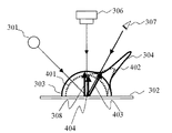
図3に、光沢特性の異なる2つの試料(光沢の高い記録媒体Aと光沢の低い記録媒体Bに印刷された画像)の反射光の空間的な分布と、一般的な測色器の幾何条件及び人が画像を観察する際の観察方向を示す。一般的な測色器は、試料の法線に対して45度傾いた方向から試料を照明して、試料の法線に対してn度傾いた方向で受光する「45−n」とよばれる幾何条件を採用している。図3は、光沢特性の異なる2つの試料において、一般的な測色器を用いて測色値を一致させた場合の反射光の空間的な分布を示している。ここでは、「45−0」の幾何条件の例を示す。試料302は光源301によって、試料の法線に対して45度傾いた方向から照明される。センサ306は、空間的に分布した反射光のうち、試料の法線方向(0度)の光量を受光する。試料302が記録媒体Aである場合と記録媒体Bである場合とで、試料302に記録された画像の測色値を一致させたときには、試料302の法線方向の拡散反射成分である反射光量308は互いに一致する。しかし、試料302の光沢特性の違いにより表面反射成分が相違する。つまり、記録媒体Aの表面反射成分304と、記録媒体Bの表面反射成分305とが相違する。一方、画像観察者307の観察方向は、詳細には観察条件によって異なるが、典型的には正反射方向から所定の角度外れた方向によって代表される。つまり、画像観察者307は所定の観察方向への反射光を観察していることになる。そのため、画像観察者307が観察する方向では、観察される光量が記録媒体Aと記録媒体Bとで異なる。つまり、画像観察者307が観察する記録媒体Aからの反射光量309と、画像観察者307が観察する記録媒体Bからの反射光量310とが相違する。即ち、記録媒体A及び記録媒体Bの反射光の空間的な分布の違いにより、測色値は一致しているが画像観察者307が観察する反射光量(見え)が相違する。
そして、特許文献1に記載の技術では、入力色信号からプリンタの色信号への変換に、測色色信号を用いているため、記録媒体の光沢特性の違いによっては色のマッチングを行ったとしても、「見え」は異なる場合がある。
According to such conventional color signal processing, it is possible to match color reproduction characteristics between different recording media. However, in the conventional color signal processing, color matching is performed using the colorimetric color signal, and therefore good color reproduction may not be possible if the gloss characteristics of the recording medium are different. This is because the illumination and sensor geometric conditions in the color measuring device (color measurement device) are different from the illumination and observation direction geometric conditions during image observation. FIG. 2 is a diagram schematically showing a spatial distribution of reflected light when a sample is illuminated with light from a light source. Light illuminated by the
FIG. 3 shows a spatial distribution of reflected light of two samples having different gloss characteristics (images printed on a recording medium A having a high glossiness and a recording medium B having a low glossiness), and general geometric conditions of a colorimeter. And an observation direction when the person observes the image. A general colorimeter is called “45-n” which illuminates a sample from a direction inclined by 45 degrees with respect to the normal line of the sample and receives light in a direction inclined by n degrees with respect to the normal line of the sample. Geometric conditions are adopted. FIG. 3 shows the spatial distribution of reflected light when two samples having different gloss characteristics are matched with colorimetric values using a general colorimeter. Here, an example of the geometric condition “45-0” is shown. The
In the technique described in
この課題を解決する技術として、異なる光沢特性を持つ記録媒体間で色のマッチングを行う際に測色値を一致させるのではなく、所定の方向での「見え」を一致させる方法が開示されている(特許文献2)。特許文献2に記載の技術は、入力色信号からプリンタの色信号へ変換する際に用いる測色色信号の代わりに、0度ではない所定の角度で測定した光量を色信号として利用することで、「見え」を一致させる方法である。図4に、異なる記録媒体間で「見え」を一致させた場合の反射光の空間的な分布を示す。画像観察者307の観察方向への反射光量403を測色色信号の代わりに利用して、記録媒体Aの「見え」に記録媒体Bの「見え」を一致させる。つまり、記録媒体Bからの表面反射成分402を、図3中の表面反射成分305よりも小さくして、画像観察者307の観察方向での反射光量を一致させる。従って、一般的な測色器のセンサの読み取る光量は、記録媒体Aからの反射光量308と記録媒体Bからの反射光量404とで異なることとなる。
As a technique for solving this problem, a method for matching the “appearance” in a predetermined direction is disclosed instead of matching the colorimetric values when color matching is performed between recording media having different gloss characteristics. (Patent Document 2). The technique described in
観察者が画像を観察する方向は、一概に規定できない場合が多い。従って、印刷画像は様々な角度から観察されることを想定する必要がある。しかしながら、従来の一般的なカラーマッチング技術では測色値を一致させており、光沢特性の異なる試料間では「見え」が異なってしまう。また、特許文献2に記載の技術では、任意の一方向で決めた「見え」を一致させているため、光沢特性の異なる試料間で、予め規定された所定の観察方向以外から観察すると両者の「見え」が異なる場合がある。つまり、観察角度を規定できない場合には、「見え」を十分に一致させることは困難である。
In many cases, the direction in which an observer observes an image cannot be defined unconditionally. Therefore, it is necessary to assume that the printed image is observed from various angles. However, in the conventional general color matching technique, the colorimetric values are matched, and “appearance” differs between samples having different gloss characteristics. In addition, in the technique described in
本発明は、光沢特性が相違する印刷媒体間においても観察方向によらず良好な色のマッチングを得ることができる画像処理装置及び画像処理方法等を提供することを目的とする。 An object of the present invention is to provide an image processing apparatus, an image processing method, and the like that can obtain good color matching between print media having different gloss characteristics regardless of the viewing direction.
本発明に係る画像処理装置は、画像信号を取得する画像信号取得手段と、前記画像信号を読み取る対象である第1の印刷媒体の第1の反射特性を取得する第1の反射特性取得手段と、前記画像信号取得手段により取得された前記画像信号の画像を記録する対象である第2の印刷媒体の第2の反射特性を取得する第2の反射特性取得手段と、前記第1の反射特性及び前記第2の反射特性のうち、互いに同一の幾何条件における複数の反射光量から算出された比較データを用いて補正量を算出するか、又は前記第1の反射特性及び前記第2の反射特性との間で互いに異なる幾何条件における反射光量から算出された比較データを用いて補正量を算出する補正量算出手段と、前記補正量を用いて前記画像信号を補正する画像補正手段と、を有することを特徴とする。 An image processing apparatus according to the present invention includes an image signal acquisition unit that acquires an image signal, and a first reflection characteristic acquisition unit that acquires a first reflection characteristic of a first print medium that is a target for reading the image signal. A second reflection characteristic acquisition unit that acquires a second reflection characteristic of a second print medium that is a target for recording an image of the image signal acquired by the image signal acquisition unit; and the first reflection characteristic. and of the second reflection characteristics, or that to calculate the correction amount using the comparison data calculated from a plurality of reflected light in the same geometrical conditions from each other, or the first reflection characteristic and the second reflection Correction amount calculation means for calculating a correction amount using comparison data calculated from reflected light amounts in different geometric conditions with respect to characteristics, and image correction means for correcting the image signal using the correction amount. Have The features.
本発明によれば、2種類の印刷媒体の反射特性に基づき画像信号を補正するため、これら印刷媒体間において観察方向によらず良好な色再現を実現することができる。 According to the present invention, since the image signal is corrected based on the reflection characteristics of two types of print media, good color reproduction can be realized between these print media regardless of the viewing direction.
以下、本発明の実施形態について添付の図面を参照して具体的に説明する。 Hereinafter, embodiments of the present invention will be specifically described with reference to the accompanying drawings.
(第1の実施形態)
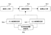
先ず、第1の実施形態について説明する。図5は、本発明の第1の実施形態に係る画像処理装置の構成を示すブロック図である。この画像処理装置には、画像入力部501、画像処理部502、画像出力部503、入力紙種設定部504、出力紙種設定部505、及び光沢特性情報格納部506が設けられている。
画像入力部501は、スキャナ等の画像入力装置であり、画像信号取得手段として、印刷対象となる画像を入力する。入力紙種設定部504は、ユーザ入力等に応じて、第1の印刷媒体である入力原稿の記録媒体の種類を設定する。出力紙種設定部505は、ユーザ入力等に応じて、第2の印刷媒体である画像入力部501が入力した画像を出力する対象である記録媒体の種類を設定する。光沢特性情報格納部506には、予め記録媒体の光沢特性の情報が、第1の反射特性及び第2の反射特性の情報として、格納されている。光沢特性(反射特性)には、例えば測色器における照明及びセンサ(受光)の種々の幾何条件における反射光量群が含まれている。画像処理部502は、光沢特性情報格納部506を参照して、画像入力部501が入力した画像の画像信号に対し、入力紙種設定部504及び出力紙種設定部505により設定された各記録媒体の光沢特性情報を取得し、画像処理を実施する。画像出力部503は、プリンタ等の記録装置であり、画像処理部502により処理された画像を、出力紙種設定部505により設定された記録媒体に印刷する。
(First embodiment)
First, the first embodiment will be described. FIG. 5 is a block diagram showing the configuration of the image processing apparatus according to the first embodiment of the present invention. This image processing apparatus includes an
The
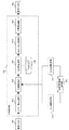
図6は、画像処理部502の詳細を示すブロック図である。画像処理部502には、入力γ補正部601、色変換処理部602、色分解処理部603、出力γ補正処理部604、中間調処理部605、及び色分解ルックアップテーブル(LUT)606が設けられている。
入力γ補正部601は、画像入力部501が入力した画像の画像信号と輝度との関係を線形にするような変換処理を行う。色変換処理部602は、詳細は後述するが、画像信号(例えば、RGB値)から、入力紙種設定部504及び出力紙種設定部505により設定された各記録媒体の光沢特性情報に対応した画像出力部503の画像信号(例えば、プリンタのRGB値)への変換を行う。色分解処理部603は、色変換処理部602による変換後のRGB値から、画像出力部503に搭載されている各色材色の信号値(例えば、CMYK値)への変換を行う。この変換としては、例えば、色分解LUT606を参照しての各色材色の信号値への変換が行われる。出力γ補正処理部604は、色分解処理部603による変換後の信号値に対する、記録媒体に印刷された画像の階調を良好にするための明度変換処理(例えばガンマ補正処理)を行う。この明度変換処理には、例えば、輝度、明度、濃度等の情報が用いられる。中間調処理部605は、出力γ補正処理部604によるガンマ補正処理後の各色材色の画像信号を、画像出力部503が処理可能なビット数に変換する。
FIG. 6 is a block diagram illustrating details of the
The input γ correction unit 601 performs a conversion process that linearizes the relationship between the image signal of the image input by the
次に、第1の実施形態における色変換処理部602の詳細について説明する。本実施形態では、任意の原稿をスキャナ等の画像入力部501で読み取り、複製を作成する際に、観察する角度によらず原稿と複製の「見え」の印象をより近づけるための色変換処理を行う。図7は、第1の実施形態に係る画像処理装置の動作を示すフローチャートである。
先ず、ステップS701において、画像入力部501が、原稿から入力画像の画像信号を取得する。
次いで、ステップS702において、入力紙種設定部504が原稿に使用される記録媒体の種類を取得し、ステップS703において、出力紙種設定部505が複製に使用される記録媒体の種類を取得する。図8に、記録媒体の種類を取得するためのユーザインタフェース(UI)の一例を示す。入力紙種設定部504及び出力紙種設定部505は、例えば図8に示すUIを介してのユーザ入力に基づいて記録媒体の種類を取得する。図8に示すUIには、原稿及び複製に使用される記録媒体の種類を選択する2つのリストボックス801及び802、OKボタン803、並びにキャンセルボタン804が設けられている。リストボックス801及び802のリストには、記録装置に対応した記録媒体の種類(例えば写真用紙<光沢>、写真用紙<半光沢>、マット紙、普通紙等の代表的な記録媒体)が予め登録されている。そして、このリストの中から原稿及び複製の記録媒体の種類に対応したものがユーザによって選択される。OKボタン803が押下されると、リストボックス801及び802に選択されている記録媒体の種類が確定され、キャンセルボタン804が押下されると、リストボックス801及び802の選択は無視され、それまでに設定されている内容が維持される。
Next, details of the color
First, in step S701, the
In step S702, the input paper
その後、ステップS704において、画像処理部502が、第1の反射特性取得手段として、ステップS702において設定された記録媒体の種類に対応する光沢特性情報を光沢特性情報格納部506から取得する。更に、画像処理部502は、第2の反射特性取得手段として、ステップS705において、ステップS703において設定された記録媒体の種類に対応する光沢特性情報を光沢特性情報格納部506から取得する。光沢特性情報としては、例えば変角反射率分布の複数の角度における測定値が用いられる。変角反射率分布は、市販の変角測光器によって測定可能であり、光沢特性情報格納部506には、リストボックス801及び802に登録されている代表的な記録媒体の種類に対して、予め測定されたデータが登録されている。
図9に、記録媒体902の変角反射光分布903を、変角測光器を用いて0度、15度、30度で測定する際の模式図を示す。また、図10に、前記変角測光器を用いて前記各記録媒体について測定された、画像信号毎の複数角度における反射率データのデータテーブルの一例を示す。更に、図11に、前記変角測光器を用いて前記各記録媒体について測定された、図10に対応する変角反射率のグラフを示す。図11に示すように、印刷する記録媒体が異なると、各角度で反射率の差が異なる。図12に、カラーマッチング処理をしない場合の記録媒体A及び記録媒体Bの各角度における明度グラフを示す。
Thereafter, in step S704, the
FIG. 9 is a schematic diagram when the variable angle reflected
ステップS705の後、画像処理部502は、ステップS706において、図10に示すデータテーブルを参照して、カラーマッチング処理を実施する。このカラーマッチング処理は、主として色変換処理部602により行われる。図13は、色変換処理部602の構成を示すブロック図である。色変換処理部602には、ターゲット色変換部1301、記録媒体適応色変換部1302、色域圧縮部1303、及びプリンタ特性色変換部1304が設けられている。色変換処理部602には、更に、ターゲット色変換LUT1305、マッピングパラメータ格納部1306、及びプリンタ特性色変換LUT1307が設けられている。
After step S705, the
ターゲット色変換部1301は、ターゲット色変換LUT1305を参照して、入力された画像信号RGBを目標とする記録媒体Aでの変角色信号XA(θ)YA(θ)ZA(θ)に変換する。ここでは、変角色信号XA(θ)YA(θ)ZA(θ)として三刺激値XYZ(CIE XYZ)を用いる場合を例にとって説明する。
The target
記録媒体適応色変換部1302は、補正量算出手段として、各画像信号(0〜255)について、角度θにおける補正量dX(θ)、dY(θ)、及びdZ(θ)を以下の(1)式で求める。
dX(θ)=XB(θ)−XA(θ)
dY(θ)=YB(θ)−YA(θ) ・・・(1)
dZ(θ)=ZB(θ)−ZA(θ)
ここで、XB(θ)、YB(θ)、及びZB(θ)は、ステップS703にて設定された出力する記録媒体Bにおける三刺激値XYZであり、例えば図10のデータテーブルを参照して求められる。なお、図10に示すデータテーブルには、簡単のため反射率データを示しているが、XYZでも同様である。
例えば、0度の変角色信号XA(θ)YA(θ)ZA(θ)のデータを一致させる場合には、以下の(2)式によって、比較データとして、補正量dX(0)、dY(0)、dZ(0)が求められる。
dX(0)=XB(0)−XA(0)
dY(0)=YB(0)−YA(0) ・・・(2)
dZ(0)=ZB(0)−ZA(0)
補正量dX(0)、dY(0)、及びdZ(0)は離散的な画像信号について、求められた値(差分)であり、予め格納されている各画像信号以外の補正量は、公知の補間方法によって補間される。
更に、記録媒体適応色変換部1302は、(1)式で得られた各画像信号におけるそれぞれの角度での補正量dX(θ)、dY(θ)、及びdZ(θ)を用いて、例えば、(3)式から補正量dX、dY、及びdZを求める。
dX=w0dX(0)+w15dX(15)+w30dX(30)
dY=w0dY(0)+w15dY(15)+w30dY(30) ・・・(3)
dZ=w0dZ(0)+w15dZ(15)+w30dZ(30)
ここで、w0、w15、及びw30はそれぞれ複数角度における補正量に対応する重み付け係数であり、和が1になるように正規化されている。つまり、記録媒体適応色変換部1302は、加重平均を補正量とする。
The recording medium adaptive
dX (θ) = X B (θ) −X A (θ)
dY (θ) = Y B (θ) −Y A (θ) (1)
dZ (θ) = Z B (θ) −Z A (θ)
Here, X B (θ), Y B (θ), and Z B (θ) are the tristimulus values XYZ in the output recording medium B set in step S703. For example, the data table of FIG. Required by reference. The data table shown in FIG. 10 shows reflectance data for simplicity, but the same applies to XYZ.
For example, when the data of the 0-degree angle-change color signal X A (θ) Y A (θ) Z A (θ) are matched, the correction amount dX (0) is used as comparison data according to the following equation (2). , DY (0), dZ (0) are obtained.
dX (0) = X B (0) −X A (0)
dY (0) = Y B (0) −Y A (0) (2)
dZ (0) = Z B (0) −Z A (0)
Correction amounts dX (0), dY (0), and dZ (0) are values (differences) obtained for discrete image signals, and correction amounts other than each image signal stored in advance are known. Is interpolated by the interpolation method.
Further, the recording medium adaptive
dX = w 0 dX (0) + w 15 dX (15) + w 30 dX (30)
dY = w 0 dY (0) + w 15 dY (15) + w 30 dY (30) (3)
dZ = w 0 dZ (0) + w 15 dZ (15) + w 30 dZ (30)
Here, w 0 , w 15 , and w 30 are weighting coefficients corresponding to correction amounts at a plurality of angles, respectively, and are normalized so that the sum is 1. That is, the recording medium adaptive
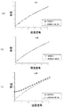
w0=0.25、w15=0.25、w30=0.5である場合の、各角度における明度グラフを図14に示す。また、比較のために、図15に、測色値を一致させる一般的なカラーマッチング処理をした場合の記録媒体Aと記録媒体Bの各角度における明度グラフを示す。更に、比較のために、図16に、特許文献2に記載されている所定の角度(ここでは、30度)での「見え」を一致させる処理を施した際の、各角度における明度グラフを示す。
図15に示す明度グラフでは、0度及び15度では記録媒体Aと記録媒体Bとで明度がほぼ一致しているのに対して、30度では大きな明度差が発生している。つまり、30度で観察した場合には、「見え」が異なってしまう。また、図16に示す明度グラフでは、(1)式のθを30度とする処理が行われているため、30度では記録媒体Aと記録媒体Bとで明度がほぼ一致している。しかし、0度及び15度では大きな明度差が発生している。つまり、0度及び15度で観察した場合には、「見え」が異なってしまう。これらの傾向は、色相及び彩度についても同様である。
これらに対し、図14に示す明度グラフでは、全ての角度において、記録媒体Aと記録媒体Bとで明度が厳密に一致してはいないが、観察角度の違いによる「見え」の違いが抑制されている。例えば、図15に示す明度グラフ(0度で一致させた場合)と比較して、30度の明度差が抑制されている。また、図16に示す明度グラフ(30度で一致させた場合)と比較して、0度及び15度の明度差が抑制されている。
このように、本実施形態では、光沢特性の異なる記録媒体A及び記録媒体B間において観察方向によらず良好な色再現が得られる。
そして、記録媒体適応色変換部1302は、画像補正手段として、補正量dX、dY、及びdZを用いて、変角色信号XAYAZAを変角色信号XBYBZBに変換する。
FIG. 14 shows a lightness graph at each angle when w 0 = 0.25, w 15 = 0.25, and w 30 = 0.5. For comparison, FIG. 15 shows a brightness graph at each angle of the recording medium A and the recording medium B when a general color matching process for matching the colorimetric values is performed. Furthermore, for comparison, FIG. 16 shows a brightness graph at each angle when the process of matching the “appearance” at a predetermined angle (here, 30 degrees) described in
In the brightness graph shown in FIG. 15, the brightness of the recording medium A and the recording medium B are substantially the same at 0 degree and 15 degrees, but a large brightness difference is generated at 30 degrees. That is, when viewed at 30 degrees, the “appearance” is different. In the lightness graph shown in FIG. 16, since the process of setting θ in equation (1) to 30 degrees is performed, the lightness of the recording medium A and the recording medium B is almost the same at 30 degrees. However, a large brightness difference occurs at 0 degrees and 15 degrees. That is, when observed at 0 degrees and 15 degrees, the “appearance” is different. These tendencies also apply to hue and saturation.
On the other hand, in the brightness graph shown in FIG. 14, the brightness does not exactly match between the recording medium A and the recording medium B at all angles, but the difference in “appearance” due to the difference in observation angle is suppressed. ing. For example, compared to the brightness graph shown in FIG. 15 (when matched at 0 degree), the brightness difference of 30 degrees is suppressed. Moreover, compared with the lightness graph shown in FIG. 16 (when matched at 30 degrees), the lightness difference of 0 degrees and 15 degrees is suppressed.
Thus, in this embodiment, good color reproduction can be obtained between the recording medium A and the recording medium B having different gloss characteristics regardless of the observation direction.
Then, the recording medium adaptive
色域圧縮部1303は、変角色信号XBYBZBを実際に印刷する記録媒体Bで再現できる変角色信号XMYMZMに変換する。マッピングパラメータ格納部1306に、彩度の圧縮条件に関するパラメータが格納されており、色域圧縮部1303は、このパラメータを利用して、公知の色域圧縮方法によって色信号を変換する。
プリンタ特性色変換部1304は、変角色信号XMYMZMを画像出力部503(ここでは、プリンタ)の色信号RpGpBpに変換する。この変換は、ターゲット色変換部1201と同様、3DLUTを用いて行われる。ここで使用されるプリンタ特性色変換LUT1307は、離散的なプリンタの色信号と該色信号に対応する記録媒体Bでの測色信号との関係を示すものであり、公知の補間方法によって変換できる。
The color
The printer characteristic
これら一連の処理により、入力信号RGBが、プリンタの色信号RpGpBpに変換される。 Through this series of processing, the input signal RGB is converted into the color signal R p G p B p of the printer.
なお、上記の例では、0度、15度、30度の3角度のデータから補正量を算出しているが、補正量の算出方法はこれに限定されるものではなく、(3)式に記載した補正量の算出方法は、下記(4)式のように一般化できる。
dX=ΣwidX(θi)
dY=ΣwidY(θi) ・・・(4)
dZ=ΣwidZ(θi)
In the above example, the correction amount is calculated from data of three angles of 0 degrees, 15 degrees, and 30 degrees. However, the correction amount calculation method is not limited to this, and the expression (3) is used. The correction amount calculation method described can be generalized as shown in the following equation (4).
dX = Σw i dX (θ i )
dY = Σw i dY (θ i ) (4)
dZ = Σw i dZ (θ i )
また、補正量を、ステップS704及びS705で取得された複数角度における反射率から、次の処理によって求めてもよい。
記録媒体Aに対応する角度θ方向への反射率をRA(θ)、複製Bに対応する角度θ方向への反射率をRB(θ)とすると、角度θ方向への補正パラメータH(θ)は、(5)式で表される。
H(θ)=RB(θ)/RA(θ) ・・・(5)
従って、角度θ1〜θnにおいて補正パラメータH(θ1)〜H(θn)が算出される。(4)式と同様に、複数の補正パラメータH(θ1)〜H(θn)の重み付け平均を取ったHmを実際の補正処理で使用する。
Hm=ΣwiH(θi)
ここで、w1〜wnはそれぞれ複数の方向における補正パラメータに対応する重み付け係数であり、和が1になるように正規化される。そして、Hmを前記XA、YA、ZAに乗算することで、前記XB、YB、ZBが得られる。
Further, the correction amount may be obtained by the following process from the reflectance at a plurality of angles acquired in steps S704 and S705.
When the reflectance in the angle θ direction corresponding to the recording medium A is R A (θ) and the reflectance in the angle θ direction corresponding to the copy B is R B (θ), the correction parameter H ( θ) is expressed by equation (5).
H (θ) = R B (θ) / R A (θ) (5)
Therefore, the correction in the angle theta 1 through? N parameter H (θ 1) ~H (θ n) is calculated. Similarly to the equation (4), H m obtained by taking a weighted average of a plurality of correction parameters H (θ 1 ) to H (θ n ) is used in actual correction processing.
H m = Σw i H (θ i )
Here, w 1 to w n are weighting coefficients corresponding to correction parameters in a plurality of directions, respectively, and are normalized so that the sum becomes 1. Then, X B , Y B , and Z B are obtained by multiplying X A , Y A , and Z A by H m .
なお、重み付け係数の決め方としては、例えばw1=w2=・・・=wnとして補正パラメータH(θ1)〜H(θn)の平均値を算出してもよく、また、原稿及び複製の光沢特性の違いにより決定してもよい。両記録媒体間で所定の方向での「見え」を一致させた際に、両記録媒体間の光沢特性の違いが大きい場合、観察方向以外の方向から観察したときの色が合わなくなってしまう。したがって、光沢特性の違いが所定の値より大きい場合には、観察方向への重み付け係数を小さくし、観察方向からのずれが大きい角度に対応する重み付け係数の値を大きくすることが好ましい。
例えば、補正パラメータH(θ1)〜H(θn)に対し、以下の(6)式を計算する。
dH(θi)=|H(θi)−1| ・・・(6)
(6)式により得られるdH(θi)の値が小さければ、角度θiにおける両記録媒体間の反射率が近いということを意味し、dH(θi)の値が大きければ角度θiにおける両記録媒体間の反射率が異なっていることを意味する。そこで、角度θiにおける重み付け係数を次式により算出する。
wi=1/dH(θi) ・・・(7)
ただし、(7)式により得られる重み付け係数は、和が1になるよう正規化される。(7)式を用いることにより、反射率の違いが大きい角度での補正パラメータの影響が相対的に小さくなり、光沢特性の違いが大きい記録媒体間で、所定角度以外の「見え」の印象をより近づける補正が可能になる。
As the method of determining the weighting factors, for example, w 1 = w 2 = ··· = w n as the correction parameter H (θ 1) ~H may calculate an average value of (theta n), The document and You may decide by the difference in the gloss characteristic of reproduction. When the “appearance” in the predetermined direction is matched between the two recording media, if the difference in gloss characteristics between the two recording media is large, the colors when viewed from a direction other than the viewing direction will not match. Therefore, when the difference in gloss characteristics is larger than a predetermined value, it is preferable to decrease the weighting coefficient in the observation direction and increase the value of the weighting coefficient corresponding to the angle where the deviation from the observation direction is large.
For example, the following equation (6) is calculated for the correction parameters H (θ 1 ) to H (θ n ).
dH (θ i ) = | H (θ i ) −1 | (6)
If the value of dH (θ i ) obtained by equation (6) is small, it means that the reflectance between the recording media at the angle θ i is close, and if the value of dH (θ i ) is large, the angle θ i. This means that the reflectance between the two recording media is different. Therefore, the weighting coefficient at the angle θ i is calculated by the following equation.
w i = 1 / dH (θ i ) (7)
However, the weighting coefficient obtained by the equation (7) is normalized so that the sum becomes 1. By using the expression (7), the influence of the correction parameter at an angle where the difference in reflectance is large becomes relatively small, and an impression of “appearance” other than the predetermined angle is obtained between recording media where the difference in gloss characteristics is large. Correction that makes it closer is possible.
このような第1の実施形態によれば、記録媒体の種類に応じて、「見え」を考慮した好適なカラーマッチング処理が実現できる。 According to such a first embodiment, it is possible to realize a suitable color matching process in consideration of “appearance” according to the type of recording medium.
なお、補正量として、変角色信号XA(θ)YA(θ)ZA(θ)と変角色信号XB(θ)YB(θ)ZB(θ)との比を用いてもよい。 As a correction amount, a ratio between the angle-change color signal X A (θ) Y A (θ) Z A (θ) and the angle-change color signal X B (θ) Y B (θ) Z B (θ) may be used. Good.
(第2の実施形態)
次に、第2の実施形態について説明する。上記のように、第1の実施形態では、原稿と複製とで用いる記録媒体間の光沢特性との違いに基づき、どの方向から観察した際にも色の「見え」の印象をより近づけるための、画像信号の補正処理を行う。しかし、観察環境はユーザによって異なり、所定の観察条件で観察するという用途もある。そこで、第2の実施形態では、ユーザの指示に基づいて、補正処理の内容を切り替える。図17に、原稿及び複製のそれぞれの観察条件に対応する表の一例を示す。図17中の(a)〜(h)に対応して、画像処理部502は、補正処理の内容を切り替える。
(Second Embodiment)
Next, a second embodiment will be described. As described above, in the first embodiment, based on the difference in gloss characteristics between the recording media used for the original and the copy, it is possible to make the impression of color “appearance” closer when viewed from any direction. Then, the image signal correction processing is performed. However, the observation environment varies depending on the user, and there is a use in which observation is performed under predetermined observation conditions. Therefore, in the second embodiment, the content of the correction process is switched based on a user instruction. FIG. 17 shows an example of a table corresponding to the observation conditions of the original and the copy. Corresponding to (a) to (h) in FIG. 17, the
図18は、第2の実施形態の動作を示すフローチャートである。
先ず、ステップS1801において、画像処理部502が、ユーザによって指定された観察条件を取得する。図19に、ユーザが観察条件を選択できるUIの一例を示す。このUIには、観察条件設定ウインドウ1901が設けられている。観察条件設定ウインドウ1901は、例えば使用されるプリンタのドライバに実装されている。その他、別アプリケーションとして実装されていても構わない。このUIには、更に、原稿の観察角度の「可変」、「固定」をユーザによって二者択一で選択されるラジオボタン1902及び1903が設けられている。ラジオボタン1903が選択された場合、つまり、原稿の観察角度「固定」が選択された場合、グループボックス1904が入力可能な状態になる。ラジオボタン1903が選択されるまでは、グループボックス1904がグレイアウトし、入力不可の状態であることが好ましい。グループボックス1904には、原稿観察時の照明の試料に対する角度を入力するテキストボックス1905、及び原稿観察時の原稿に対する観察角度を入力するテキストボックス1906が含まれている。このUIには、更に、複製の観察角度の「可変」、「固定」をユーザによって二者択一で選択されるラジオボタン1907及び1908が設けられている。ラジオボタン1908が選択された場合、つまり、複製の観察角度「固定」が選択された場合、グループボックス1909が入力可能な状態になる。ラジオボタン1908が選択されるまでは、グループボックス1909がグレイアウトし、入力不可の状態であることが好ましい。グループボックス1909には、複製観察時の照明の複製に対する角度を入力するテキストボックス1910、及び複製観察時の複製に対する観察角度を入力するテキストボックス1911が含まれている。OKボタン1912が押下されると、選択された原稿及び複製の観察条件が確定し、画像処理部502がこの内容を取得する。キャンセルボタン1913が押下されると、上述された選択内容は破棄され、処理を取り止める。なお、上述のラジオボタン、グループボックス、テキストボックス等は、一例であり、その他同等の機能を有するオブジェクトであれば代用可能である。
FIG. 18 is a flowchart showing the operation of the second embodiment.
First, in step S1801, the
次いで、ステップS1802において、入力紙種設定部504が原稿に使用される記録媒体の種類を取得し、ステップS1803において、出力紙種設定部505が複製に使用される記録媒体の種類を取得する。つまり、ステップS702及びS703と同様の処理が行われる。
その後、ステップS1804において、画像処理部502は、原稿及び複製の記録媒体の種類が同じか否かの判定を行う。そして、原稿及び複製の記録媒体の種類が等しい場合、ステップS1805において、画像処理部502は、『原稿及び複製の両者の観察角度が「可変」』、又は、『原稿及び複製が常に同じ角度で観察される』という条件が成り立つか否かの判定を行う。この条件が満たされる場合、画像処理部502は、ステップS1809において、測色値を一致させるカラーマッチング処理を実施する。使用する記録媒体が原稿及び複製で等しい場合、測色値、即ち、所定の幾何条件における反射光量を一致させれば、変角反射率も一致する。そのため、原稿及び複製を同じ角度で観察しさえすれば、どの角度から観察しても色の「見え」は一致する。また、原稿及び複製の両者の観察角度を規定できない場合、第1の実施形態と同様の処理結果を得ること、即ち、どの角度から観察しても「見え」の印象が近くなることが好ましいが、使用する記録媒体が原稿と複製とで等しい場合には変角反射率が一致する。従って、測色値を一致させるカラーマッチング処理によって同一の処理結果を得ることができる。
In step S1802, the input paper
Thereafter, in step S1804, the
一方、ステップS1804において、原稿及び複製の記録媒体の種類が異なっている場合、及びステップS1805の条件が満たされていない場合、ステップS1806において、画像処理部502が、ステップS1802において設定された記録媒体の種類に対応する光沢特性情報を光沢特性情報格納部506から取得する。更に、画像処理部502は、ステップS1807において、ステップS1803において設定された記録媒体の種類に対応する光沢特性情報を光沢特性情報格納部506から取得する。つまり、ステップS704及びS705と同様の処理が行われる。
次いで、画像処理部502は、ステップS1808において、観察条件に応じたカラーマッチング処理を実施する。このカラーマッチング処理は、主として色変換処理部602により行われる。以下、原稿及び複製の種々の観察条件に応じた処理の内容について、観察条件毎に説明する。
On the other hand, if the types of the original and duplicate recording media are different in step S1804, and if the conditions in step S1805 are not satisfied, in step S1806, the
Next, in step S1808, the
先ず、原稿及び複製の観察角度が「固定」の場合の処理について説明する。このような場合としては、例えば、原稿と複製が壁等に掛けられた状態で、ある一定距離以上離れた位置から観察する場合が考えられる。ある一定距離以上離れた位置から観察することで、観察角度はほぼ等しくなる。
観察条件設定ウインドウ1901において、原稿及び複製の観察条件が「固定」かつ「観察方向0度」が選択された場合、色変換処理部602は、互いに同一の幾何条件における反射光量から算出された比較データを用いて、測色値を一致させる一般的なカラーマッチング処理を実施する。この場合は、図17中の(a)に該当し、図15に示すような明度グラフが得られる。
観察条件設定ウインドウ1901において、原稿及び複製の観察条件が「固定」かつ「観察方向が0度以外の同じ角度」が選択された場合、色変換処理部602は、互いに同一の幾何条件における反射光量から算出された比較データを用いて、選択された所定の角度での「見え」を一致させるカラーマッチング処理を実施する。この場合は、図17中の(b)に該当し、図16に示すような明度グラフが得られる。
観察条件設定ウインドウ1901において、原稿及び複製の観察条件が「固定」かつ「原稿と複製でそれぞれ異なる観察角度」が選択された場合、色変換処理部602は、選択された所定の角度での「見え」を一致させるカラーマッチング処理を実施する。つまり、色変換処理部602は、互いに異なる幾何条件における反射光量から算出された比較データを用いてカラーマッチング処理を実施する。この場合は、図17中の(c)に該当する。この場合、色変換処理部602は、以下の(8)式から補正量dX、dY、dZを求める。つまり、色変換処理部602は、第1の実施形態の所定角度での「見え」を一致させる場合と同様の補正処理を実施する。
dX=XB(θ2)−XA(θ1)
dY=YB(θ2)−YA(θ1) ・・・(8)
dZ=ZB(θ2)−ZA(θ1)
First, processing when the observation angle of the original and the copy is “fixed” will be described. As such a case, for example, a case where observation is performed from a position separated by a certain distance or more with a document and a copy hung on a wall or the like can be considered. By observing from a position separated by a certain distance or more, the observation angles become substantially equal.
In the observation
In the observation
In the observation
dX = X B (θ 2 ) −X A (θ 1 )
dY = Y B (θ 2 ) −Y A (θ 1 ) (8)
dZ = Z B (θ 2 ) −Z A (θ 1 )
次に、原稿の観察角度が「固定」、複製の観察角度が「可変」の場合の処理について説明する。このような場合としては、例えば、原稿が壁等に掛けられた状態である一定距離以上離れた位置から観察し、複製を手に持って、又は机等に平置きした状態で、自由な角度から観察しながら両者を比較する場合が考えられる。原稿の観察角度が「固定」の場合、複製の観察角度が「可変」であっても、画像観察者が両者を比較するときには、原稿の「見え」と極力同じ「見え」になる角度で複製を観察することが多いため、ある角度で「見え」が一致していることが好ましい。
観察条件設定ウインドウ1901において、原稿の観察条件が「固定」かつ「0度」、複製の観察条件が「可変」と選択された場合、色変換処理部602は、複製の観察角度「0度」で「見え」が一致するように、測色値を一致させるカラーマッチング処理を実施する。この場合は、図17中の(d)に該当し、図15に示すような明度グラフが得られる。また、複製の観察角度は厳密に規定できないため、原稿を0度から観察した場合と複製を複数の角度から観察した場合の見えの印象を一致させる処理を実施してもよい。つまり、原稿(記録媒体A)の観察角度を0度、複製(記録媒体B)の観察角度をθi度とし、補正量dX、dY、及びdZを以下の(9)式から求めてもよい。この場合、色変換処理部602は、第1の実施形態の所定角度での「見え」を一致させる場合と同様の補正処理を実施する。
dX=Σwi{XB(0)−XA(θi)}
dY=Σwi{YB(0)−YA(θi)} ・・・(9)
dZ=Σwi{ZB(0)−ZA(θi)}
なお、wiは重み付け係数であり、Σwi=1となるよう正規化されている。また、wiのそれぞれの値は、第1の実施形態と同様な処理によって決定することができる。
観察条件設定ウインドウ1901において、原稿の観察条件が「固定」かつ「0度以外」、複製の観察条件が「可変」と選択された場合、色変換処理部602は、指定された原稿の観察角度と等しい角度の「見え」を一致させるカラーマッチング処理を実施する。この場合は、図17中の(e)に該当し、図16に示すような明度グラフが得られる。また、複製の観察角度は厳密に規定できないため、原稿を0度から観察した場合と複製を複数の角度から観察した場合の見えの印象を一致させる処理を実施してもよい。つまり、原稿(記録媒体A)の観察角度をθA度、複製(記録媒体B)の観察角度をθi度とし、補正量dX、dY、及びdZを以下の(10)式から求めてもよい。この場合、色変換処理部602は、第1の実施形態の所定角度での「見え」を一致させる場合と同様の補正処理を実施する。
dX=Σwi{XB(0)−XA(θi)}
dY=Σwi{YB(0)−YA(θi)} ・・・(10)
dZ=Σwi{ZB(0)−ZA(θi)}
Next, processing when the document observation angle is “fixed” and the copy observation angle is “variable” will be described. In such a case, for example, the original can be observed from a position that is a predetermined distance or more away from being hung on a wall, etc., and a free angle can be obtained while holding a copy or placing it on a desk or the like. It is possible to compare the two while observing. When the viewing angle of the document is “fixed”, even if the viewing angle of the copy is “variable”, when the image observer compares the two, the copy is made at an angle that makes the “view” as close as possible to the “view” of the document. Therefore, it is preferable that the “appearances” match at a certain angle.
In the observation
dX = Σw i {X B (0) −X A (θ i )}
dY = Σw i {Y B (0) −Y A (θ i )} (9)
dZ = Σw i {Z B (0) −Z A (θ i )}
Note that w i is a weighting coefficient and is normalized so that Σw i = 1. Further, each value of w i can be determined by the same processing as in the first embodiment.
In the viewing
dX = Σw i {X B (0) −X A (θ i )}
dY = Σw i {Y B (0) −Y A (θ i )} (10)
dZ = Σw i {Z B (0) −Z A (θ i )}
次に、原稿の観察角度が「可変」、複製の観察角度が「固定」の場合の処理について説明する。このような場合としては、例えば、複製が壁等に掛けられた状態で、ある一定距離以上離れた位置から観察し、原稿を手に持って、又は机等に平置きした状態で、自由な角度から観察しながら両者を比較する場合が考えられる。原稿の観察角度が「可変」の場合、複製の観察角度が「固定」であっても、画像観察者が両者を比較するときには、複製の「見え」と極力同じ「見え」になる角度で原稿を観察することが多いため、ある角度で「見え」が一致していることが好ましい。また、その際に観察される角度は、原稿の「見え」が特に良好であると感じられる角度であることが好ましい。
観察条件設定ウインドウ1901において、原稿の観察条件が「可変」、複製の観察条件が「固定」かつ「0度」と選択された場合、色変換処理部602は、複製の「0度」の色が原稿の「見え」が特に良好であると感じられる角度で一致するよう、カラーマッチング処理を実施する。この場合は、図17中の(f)に該当する。つまり、原稿(記録媒体A)の見えが特に良好であると感じられる観察角度をθ度、複製(記録媒体B)の観察角度を0度とし、補正量dX、dY、及びdZを以下の(11)式から求める。この場合、色変換処理部602は、第1の実施形態の所定角度での「見え」を一致させる場合と同様の補正処理を実施する。
dX=XB(0)−XA(θ)
dY=YB(0)−YA(θ) ・・・(11)
dZ=ZB(0)−ZA(θ)
なお、原稿(記録媒体A)の見えが特に良好であると感じられる観察角度θ度は、例えば、ある変角色信号から算出された色信号と予め設定された目標色信号との色差ΔE等から評価して決定してもよく、また、主観評価から決定してもよい。
観察条件設定ウインドウ1901において、原稿の観察条件が「可変」、複製の観察条件が「固定」かつ「0度以外」と選択された場合、色変換処理部602は、複製の観察角度の色が原稿の「見え」が特に良好であると感じられる角度で一致するよう、カラーマッチング処理を実施する。この場合は、図17中の(g)に該当する。つまり、原稿(記録媒体A)の見えが特に良好であると感じられる観察角度をθ1度、複製(記録媒体B)の観察角度をθ2度とし、補正量dX、dY、及びdZを以下の(12)式から求める。この場合、色変換処理部602は、第1の実施形態の所定角度での「見え」を一致させる場合と同様の補正処理を実施する。
dX=XB(θ2)−XA(θ1)
dY=YB(θ2)−YA(θ1) ・・・(12)
dZ=ZB(θ2)−ZA(θ1)
Next, processing when the document observation angle is “variable” and the copy observation angle is “fixed” will be described. In such a case, for example, when the copy is hung on a wall or the like, it is observed from a position more than a certain distance, and the manuscript is held in a hand or placed flat on a desk or the like. The case where both are compared while observing from an angle can be considered. When the viewing angle of the document is “variable”, even if the observation angle of the copy is “fixed”, when the image observer compares the two, the document is viewed at an angle that makes the “view” as close as possible to the “view” of the copy. Therefore, it is preferable that the “appearances” match at a certain angle. Further, the angle observed at that time is preferably an angle at which the “look” of the document is felt to be particularly good.
In the observation
dX = X B (0) −X A (θ)
dY = Y B (0) −Y A (θ) (11)
dZ = Z B (0) −Z A (θ)
Note that the observation angle θ degree at which the appearance of the document (recording medium A) is felt to be particularly good is, for example, from a color difference ΔE between a color signal calculated from a certain color change color signal and a preset target color signal, or the like. It may be determined by evaluation or may be determined from subjective evaluation.
In the observation
dX = X B (θ 2 ) −X A (θ 1 )
dY = Y B (θ 2 ) −Y A (θ 1 ) (12)
dZ = Z B (θ 2 ) −Z A (θ 1 )
次に、原稿及び複製の観察角度が「可変」の場合の処理について説明する。このような場合としては、例えば、原稿及び複製の両方を手に持って、又は机等に平置きした状態で、自由な角度から観察しながら両者を比較する場合が考えられる。この場合は、両者とも観察角度を規定できないため、どの角度から観察した場合でも「見え」の印象が一致していることが好ましい。したがって、色変換処理部602は、第1の実施形態と同様の補正処理を実施する。この場合、図14に示すような明度グラフが得られる。
Next, processing when the observation angle of the original and the copy is “variable” will be described. As such a case, for example, a case where both the original and the copy are held in hand or placed flat on a desk or the like may be compared while observing from a free angle. In this case, since the observation angle cannot be defined in both cases, it is preferable that the “visible” impressions coincide with each other even when viewed from any angle. Therefore, the color
このような第2の実施形態によれば、記録媒体の種類だけでなく、ユーザが指定した観察条件に応じて、「見え」を考慮した好適なカラーマッチング処理が実現できる。 According to the second embodiment as described above, it is possible to realize a suitable color matching process considering “appearance” in accordance with not only the type of recording medium but also the observation conditions specified by the user.
なお、第1の実施形態及び第2の実施形態では、照明と試料の法線の張る面内に観察者がいることを想定した処理が行われているが、実際には観察者の位置はこれに限定されない。図20に、照明の仰角θL及び方位角φL、並びに、観察方向の仰角θO及び方位角φOの関係を示す。より厳密に「見え」を一致させる処理を行う場合には、第1の実施形態及び第2の実施形態における変角色信号の代わりに、X(θL,θO,φL,φO)、Y(θL,θO,φL,φO)、Z(θL,θO,φL,φO)の測定値を利用して、上述した処理と同様の処理を行うことが好ましい。 In the first embodiment and the second embodiment, processing is performed assuming that there is an observer in the plane between the illumination and the normal line of the sample, but the position of the observer is actually It is not limited to this. FIG. 20 shows the relationship between the elevation angle θ L and the azimuth angle φ L of the illumination, and the elevation angle θ O and the azimuth angle φ O in the observation direction. In the case where the process of matching the “appearance” is performed more strictly, X (θ L , θ O , φ L , φ O ), instead of the angle-change color signal in the first and second embodiments, It is preferable to perform the same processing as described above by using the measured values of Y (θ L , θ O , φ L , φ O ) and Z (θ L , θ O , φ L , φ O ).
本発明は、複数の機器(例えばコンピュータ、インタフェース機器、リーダ、プリンタ等)から構成されるシステムに適用しても、一つの機器からなる装置(例えば、複写機、ファクシミリ装置、制御装置等)に適用してもよい。
また、本発明の各工程は、ネットワーク又は各種記憶媒体を介して取得したソフトウェア(プログラム)をパーソナルコンピュータ等の処理装置(CPU、プロセッサ)にて実行することでも実現できる。
Even if the present invention is applied to a system constituted by a plurality of devices (for example, a computer, an interface device, a reader, a printer, etc.), it is applied to an apparatus (for example, a copying machine, a facsimile machine, a control device, etc.) comprising a single device. You may apply.
Each process of the present invention can also be realized by executing software (program) acquired via a network or various storage media by a processing device (CPU, processor) such as a personal computer.
501:画像入力部 502:画像処理部 503:画像出力部 504:入力紙種設定部 505:出力紙種設定部 506:光沢特性情報格納部 602:色分解処理部 501: Image input unit 502: Image processing unit 503: Image output unit 504: Input paper type setting unit 505: Output paper type setting unit 506: Gloss characteristic information storage unit 602: Color separation processing unit
Claims (12)
前記画像信号を読み取る対象である第1の印刷媒体の第1の反射特性を取得する第1の反射特性取得手段と、
前記画像信号取得手段により取得された前記画像信号の画像を記録する対象である第2の印刷媒体の第2の反射特性を取得する第2の反射特性取得手段と、
前記第1の反射特性及び前記第2の反射特性のうち、互いに同一の幾何条件における複数の反射光量から算出された比較データを用いて補正量を算出する補正量算出手段と、
前記補正量を用いて前記画像信号を補正する画像補正手段と、
を有することを特徴とする画像処理装置。 Image signal acquisition means for acquiring an image signal;
First reflection characteristic acquisition means for acquiring a first reflection characteristic of a first print medium that is a target for reading the image signal ;
Second reflection characteristic acquisition means for acquiring a second reflection characteristic of a second print medium that is a target for recording an image of the image signal acquired by the image signal acquisition means;
A correction amount calculating means for calculating a correction amount using comparison data calculated from a plurality of reflected light amounts in the same geometric condition among the first reflection characteristic and the second reflection characteristic;
Image correcting means for correcting the image signal using the correction amount;
An image processing apparatus comprising:
前記画像信号を読み取る対象である第1の印刷媒体の第1の反射特性を取得する第1の反射特性取得手段と、
前記画像信号取得手段により取得された前記画像信号の画像を記録する対象である第2の印刷媒体の第2の反射特性を取得する第2の反射特性取得手段と、
前記第1の反射特性及び前記第2の反射特性との間で互いに異なる幾何条件における反射光量から算出された比較データを用いて補正量を算出する補正量算出手段と、
前記補正量を用いて前記画像信号を補正する画像補正手段と、
を有することを特徴とする画像処理装置。 Image signal acquisition means for acquiring an image signal;
First reflection characteristic acquisition means for acquiring a first reflection characteristic of a first print medium that is a target for reading the image signal ;
Second reflection characteristic acquisition means for acquiring a second reflection characteristic of a second print medium that is a target for recording an image of the image signal acquired by the image signal acquisition means;
A correction amount calculating means for calculating a correction amount using comparison data calculated from the amount of reflected light under different geometric conditions between the first reflection characteristic and the second reflection characteristic;
Image correcting means for correcting the image signal using the correction amount;
An image processing apparatus comprising:
前記画像信号を読み取る対象である第1の印刷媒体の第1の反射特性を取得する第1の反射特性取得ステップと、
前記画像信号取得ステップにおいて取得した前記画像信号の画像を記録する対象である第2の印刷媒体の第2の反射特性を取得する第2の反射特性取得ステップと、
前記第1の反射特性及び前記第2の反射特性のうち、互いに同一の幾何条件における複数の反射光量から算出された比較データを用いて補正量を算出する補正量算出ステップと、
前記補正量を用いて前記画像信号を補正する画像補正ステップと、
を有することを特徴とする画像処理方法。 An image signal acquisition step of acquiring an image signal;
A first reflection characteristic acquisition step of acquiring a first reflection characteristic of a first print medium that is a target for reading the image signal ;
A second reflection characteristic acquisition step of acquiring a second reflection characteristic of a second print medium that is a target for recording an image of the image signal acquired in the image signal acquisition step;
One of the first reflection characteristic and the second reflection characteristic, a correction amount calculating step that to calculate the correction amount using the comparison data calculated from a plurality of reflected light in the same geometrical conditions from each other,
An image correction step of correcting the image signal using the correction amount;
An image processing method comprising:
前記画像信号を読み取る対象である第1の印刷媒体の第1の反射特性を取得する第1の反射特性取得ステップと、A first reflection characteristic acquisition step of acquiring a first reflection characteristic of a first print medium that is a target for reading the image signal;
前記画像信号取得ステップにおいて取得した前記画像信号の画像を記録する対象である第2の印刷媒体の第2の反射特性を取得する第2の反射特性取得ステップと、A second reflection characteristic acquisition step of acquiring a second reflection characteristic of a second print medium that is a target for recording an image of the image signal acquired in the image signal acquisition step;
前記第1の反射特性及び前記第2の反射特性との間で互いに異なる幾何条件における反射光量から算出された比較データを用いて補正量を算出する補正量算出ステップと、A correction amount calculating step of calculating a correction amount using comparison data calculated from reflected light amounts in geometric conditions different from each other between the first reflection characteristic and the second reflection characteristic;
前記補正量を用いて前記画像信号を補正する画像補正ステップと、An image correction step of correcting the image signal using the correction amount;
を有することを特徴とする画像処理方法。An image processing method comprising:
画像信号を取得する画像信号取得ステップと、
前記画像信号を読み取る対象である第1の印刷媒体の第1の反射特性を取得する第1の反射特性取得ステップと、
前記画像信号取得ステップにおいて取得した前記画像信号の画像を記録する対象である第2の印刷媒体の第2の反射特性を取得する第2の反射特性取得ステップと、
前記第1の反射特性及び前記第2の反射特性のうち、互いに同一の幾何条件における複数の反射光量から算出された比較データを用いて補正量を算出する補正量算出ステップと、
前記補正量を用いて前記画像信号を補正する画像補正ステップと、
を実行させることを特徴とするプログラム。 On the computer,
An image signal acquisition step of acquiring an image signal;
A first reflection characteristic acquisition step of acquiring a first reflection characteristic of a first print medium that is a target for reading the image signal ;
A second reflection characteristic acquisition step of acquiring a second reflection characteristic of a second print medium that is a target for recording an image of the image signal acquired in the image signal acquisition step;
One of the first reflection characteristic and the second reflection characteristic, a correction amount calculating step that to calculate the correction amount using the comparison data calculated from a plurality of reflected light in the same geometrical conditions from each other,
An image correction step of correcting the image signal using the correction amount;
A program characterized by having executed.
画像信号を取得する画像信号取得ステップと、An image signal acquisition step of acquiring an image signal;
前記画像信号を読み取る対象である第1の印刷媒体の第1の反射特性を取得する第1の反射特性取得ステップと、A first reflection characteristic acquisition step of acquiring a first reflection characteristic of a first print medium that is a target for reading the image signal;
前記画像信号取得ステップにおいて取得した前記画像信号の画像を記録する対象である第2の印刷媒体の第2の反射特性を取得する第2の反射特性取得ステップと、A second reflection characteristic acquisition step of acquiring a second reflection characteristic of a second print medium that is a target for recording an image of the image signal acquired in the image signal acquisition step;
前記第1の反射特性及び前記第2の反射特性との間で互いに異なる幾何条件における反射光量から算出された比較データを用いて補正量を算出する補正量算出ステップと、A correction amount calculating step of calculating a correction amount using comparison data calculated from reflected light amounts in geometric conditions different from each other between the first reflection characteristic and the second reflection characteristic;
前記補正量を用いて前記画像信号を補正する画像補正ステップと、An image correction step of correcting the image signal using the correction amount;
を実行させることを特徴とするプログラム。A program characterized by having executed.
Priority Applications (1)
| Application Number | Priority Date | Filing Date | Title |
|---|---|---|---|
| JP2010246762A JP5693153B2 (en) | 2010-11-02 | 2010-11-02 | Image processing apparatus and image processing method |
Applications Claiming Priority (1)
| Application Number | Priority Date | Filing Date | Title |
|---|---|---|---|
| JP2010246762A JP5693153B2 (en) | 2010-11-02 | 2010-11-02 | Image processing apparatus and image processing method |
Publications (3)
| Publication Number | Publication Date |
|---|---|
| JP2012100122A JP2012100122A (en) | 2012-05-24 |
| JP2012100122A5 JP2012100122A5 (en) | 2013-12-19 |
| JP5693153B2 true JP5693153B2 (en) | 2015-04-01 |
Family
ID=46391539
Family Applications (1)
| Application Number | Title | Priority Date | Filing Date |
|---|---|---|---|
| JP2010246762A Active JP5693153B2 (en) | 2010-11-02 | 2010-11-02 | Image processing apparatus and image processing method |
Country Status (1)
| Country | Link |
|---|---|
| JP (1) | JP5693153B2 (en) |
Families Citing this family (3)
| Publication number | Priority date | Publication date | Assignee | Title |
|---|---|---|---|---|
| JP5909887B2 (en) * | 2011-06-14 | 2016-04-27 | セイコーエプソン株式会社 | Image processing apparatus, printing apparatus, image processing method, and lookup table generation method |
| JP6363916B2 (en) * | 2014-09-02 | 2018-07-25 | キヤノン株式会社 | Image processing apparatus and method |
| JP7019387B2 (en) * | 2017-11-17 | 2022-02-15 | キヤノン株式会社 | Image processing equipment, image processing methods, and programs, and image forming equipment |
Family Cites Families (4)
| Publication number | Priority date | Publication date | Assignee | Title |
|---|---|---|---|---|
| JP4401955B2 (en) * | 2004-03-03 | 2010-01-20 | キヤノン株式会社 | Color processing apparatus and method |
| JP2005260704A (en) * | 2004-03-12 | 2005-09-22 | Fuji Xerox Co Ltd | Color proofreading system and color correction method |
| JP2006066983A (en) * | 2004-08-24 | 2006-03-09 | Konica Minolta Medical & Graphic Inc | Method and apparatus for forming area gradation image |
| JP4960840B2 (en) * | 2007-11-20 | 2012-06-27 | キヤノン株式会社 | Image processing apparatus and image processing method |
-
2010
- 2010-11-02 JP JP2010246762A patent/JP5693153B2/en active Active
Also Published As
| Publication number | Publication date |
|---|---|
| JP2012100122A (en) | 2012-05-24 |
Similar Documents
| Publication | Publication Date | Title |
|---|---|---|
| JP4623137B2 (en) | Color processing apparatus, method and program | |
| JP5713727B2 (en) | Profile creation method, profile creation apparatus, image processing apparatus and program for performing color conversion by profile | |
| JP3673533B2 (en) | Calibration device for calibrating a color printer | |
| CA2345908C (en) | On-line calibration system for a dynamically varying color marking device | |
| US7880931B2 (en) | Image processing apparatus and its method, and control method | |
| JP5699661B2 (en) | Image processing apparatus, image processing method, and image processing program | |
| US7764400B2 (en) | Hard copy out of gamut detection | |
| JP2006217181A (en) | Color processing device and method | |
| JP5693153B2 (en) | Image processing apparatus and image processing method | |
| JP2008278054A (en) | Color processing apparatus and its method | |
| JP4910860B2 (en) | Image file creation device, image processing device, image processing system, and program | |
| JP2012044475A (en) | Image processing method and image output device | |
| JP2002247394A (en) | Method of preparing color converting rule, method of converting color, and colored image forming device | |
| US7796298B2 (en) | Image processing method, image processing apparatus, and storage medium | |
| JP2008177783A (en) | Color conversion device and program | |
| JP5682759B2 (en) | Bronzing index value calculation method and bronzing index value calculation device | |
| JP4881146B2 (en) | Information processing apparatus and method | |
| JPH09219800A (en) | Color image processor | |
| JP4086562B2 (en) | Image processing apparatus, image processing apparatus control method, computer program, and recording medium | |
| US7557955B2 (en) | System and method for matching colorimetric attributes of a production print to a proof | |
| JP2003324619A (en) | Image processing equipment and its control method | |
| US8363267B2 (en) | Image forming apparatus and color converting method thereof | |
| JP2003298854A (en) | Image processor and method therefor | |
| JP5903946B2 (en) | Color processing apparatus and color processing program | |
| JP2001036762A (en) | Device and method for preparing color correction definition |
Legal Events
| Date | Code | Title | Description |
|---|---|---|---|
| A521 | Written amendment |
Free format text: JAPANESE INTERMEDIATE CODE: A523 Effective date: 20131105 |
|
| A621 | Written request for application examination |
Free format text: JAPANESE INTERMEDIATE CODE: A621 Effective date: 20131105 |
|
| A977 | Report on retrieval |
Free format text: JAPANESE INTERMEDIATE CODE: A971007 Effective date: 20140902 |
|
| A131 | Notification of reasons for refusal |
Free format text: JAPANESE INTERMEDIATE CODE: A131 Effective date: 20140930 |
|
| A521 | Written amendment |
Free format text: JAPANESE INTERMEDIATE CODE: A523 Effective date: 20141128 |
|
| TRDD | Decision of grant or rejection written | ||
| A01 | Written decision to grant a patent or to grant a registration (utility model) |
Free format text: JAPANESE INTERMEDIATE CODE: A01 Effective date: 20150106 |
|
| A61 | First payment of annual fees (during grant procedure) |
Free format text: JAPANESE INTERMEDIATE CODE: A61 Effective date: 20150203 |
|
| R151 | Written notification of patent or utility model registration |
Ref document number: 5693153 Country of ref document: JP Free format text: JAPANESE INTERMEDIATE CODE: R151 |